multilevel fast-multipole algorithm for scattering from conducting
TRANSCRIPT

IEEE TRANSACTIONS ON GEOSCIENCE AND REMOTE SENSING, VOL. 38, NO. 4, JULY 2000 1561
Multilevel Fast-Multipole Algorithm for Scatteringfrom Conducting Targets Above or Embedded in a
Lossy Half SpaceNorbert Geng, Member, IEEE, Anders Sullivan, Member, IEEE, and Lawrence Carin, Senior Member, IEEE
Abstract—An extension of the multilevel fast multipole algo-rithm (MLFMA), originally developed for targets in free space,is presented for the electromagnetic scattering from arbitrarilyshaped three-dimensional (3-D), electrically large, perfectlyconducting targets above or embedded within a lossy half space.We have developed and implemented electric-field, magnetic-field,and combined-field integral equations for this purpose. Thenearby terms in the MLFMA framework are evaluated by usingthe rigorous half-space dyadic Green’s function, computed via themethod of complex images. Non-nearby (far) MLFMA interac-tions, handled efficiently within the multilevel clustering construct,employ an approximate dyadic Green’s function. This is expressedin terms of a direct-radiation term plus a single real image(representing the asymptotic far-field Green’s function), with theimage amplitude characterized by the polarization-dependentFresnel reflection coefficient. Examples are presented to validatethe code through comparison with a rigorous method-of-moments(MoM) solution. Finally, results are presented for scattering froma model unexploded ordnance (UXO) embedded in soil and for arealistic 3-D vehicle over soil.
Index Terms—Fast algorithms, method of moments (MoM), nu-merical methods, scattering.
I. INTRODUCTION
E LECTROMAGNETIC scattering from surface and sub-surface targets has constituted a problem of long-term
interest. Considering numerical modeling of such problems,there has been interest in integral-equation [1]–[3] and dif-ferential-equation [4]–[6] based methods. Investigators haveconsidered method-of-moments (MoM) [1]–[3], [7]–[9] andfinite-element method (FEM) [6], [9], [10] solutions. The prin-cipal focus in the context of time-domain differential-equationsolvers has been the finite difference time domain method(FDTD) [4], [5], [11] and more recently, the multiresolutiontime domain method (MRTD) [12], [13]. Each of these numer-ical techniques has its relative strengths and weaknesses, andeach is applicable to relatively small targets (with characteristictarget dimensions small relative to a few wavelengths). Thereare many applications for which the target may comprise a largenumber of wavelengths, for example, scattering from vehicles,trees, and large unexploded ordnance. The aforementionedMoM, FEM, FDTD and MRTD algorithms can handle such
Manuscript received August 31, 1999; revised March 27, 2000.N. Geng is with the Institut für Höchstfrequenztechnik und Elektronik, Uni-
versity of Karlsruhe, Karlsruhe, Germany.A. Sullivan and L. Carin are with the Department of Electrical and Computer
Engineering, Duke University, Durham, NC 27708-0291 USA.Publisher Item Identifier S 0196-2892(00)05895-2.
targets in principle, but memory requirements and computationtime become excessive.
There has consequently been significant interest recently inthe development of a new generation of fast algorithms to coverthe range of frequencies for which the above computationaltools are inappropriate and for which high-frequency asymp-totic techniques (e.g., PO, GTD, and UTD) are not applicableor are difficult to implement. For example, the fast multipolemethod (FMM) was extended to the case of electromagneticfields by Rhoklin and his colleagues [14]. More recently, Chewand colleagues have implemented the FMM [15] and extendedit to a multilevel framework [16], resulting in the multilevelfast multipole algorithm (MLFMA) [17]–[20]. The MLFMAhas been developed for electric-field, magnetic-field, andcombined-field integral equations for both perfectly conducting[17]–[19] and dielectric targets [20].
The FMM and MLFMA exploit a particular expansion of thefree-space Green’s function [14], [15], [21] and therefore, virtu-ally all implementations to date have been relegated to the caseof targets in free space. There have been layered-medium resultspresented for the case of two-dimensional (2-D) scattering [22],as well as quasi-planar three-dimensional (3-D) problems in cir-cuit and antenna design [23]. The difficulty of directly applyingthe FMM/MLFMA formalism to general 3-D layered-mediumproblems resides in the fact that the layered-medium Green’sfunction is a dyadic, each term of which is represented in termsof a generally complicated Sommerfeld integral [8], [24]. Onecan use the complex-image technique [25]–[27] to representeach term of the dyadic in terms of a sum of images, generallylocated in complex space. Therefore, in principle, one can applythe fundamental FMM/MLFMA expansion to each term of thisexpansion. However, we have demonstrated [28], [29] that forthe general case, the convergence (for complex image points)is often considerably slower than when source and observer arein real space. This mitigates the attractiveness of the underlyingformalism.
In [28], [29], we therefore developed an approximatemeans of handling the dyadic half-space Green’s function,with application to the FMM. In particular, the near FMMterms are evaluated via the use of the exact dyadic Green’sfunction, the latter evaluated efficiently via the complex-imagetechnique [25]–[27]. This part of the model is exactly as in arigorous MoM analysis of scattering from targets in the vicinityof a half space [3], [8]. The far terms, evaluated efficientlyvia the clustering algorithm, employ the asymptotic form ofthe dyadic Green’s function [30]. As elucidated further in
0196–2892/00$10.00 © 2000 IEEE

1562 IEEE TRANSACTIONS ON GEOSCIENCE AND REMOTE SENSING, VOL. 38, NO. 4, JULY 2000
the following, each component of the approximate Green’sfunction is expressed in terms of the direct-radiation term plusradiation from an image source in real space [28]–[30]. Theformer accounts for the radiation of currents into the medium inwhich it resides, while the latter accounts for interactions withthe half-space interface. The above approximation exploits thefact that the near interactions are most sensitive to accurateGreen’s-function evaluation, while the far interactions shouldbe less so (the far interactions within the MLFMA formalismare always at least about half a wavelength apart [17]–[20]).Therefore, the half-space MLFMA presented here differs fromthe free-space MLFMA [17]–[20] in several ways. First, thenearby interactions are handled rigorously through use of thecomplete dyadic half-space Green’s function, since these arelikely to be most susceptible to approximations in the Green’sfunction. For far interactions, we utilize the standard MLFMAclustering, with the interactions between such constituting theaforementioned direct radiation contribution. Finally, a separateset of image clusters, at real spatial positions, constitute thereflected component of the radiated fields. As is well known,the free-space FMM has O( ) memory and computational(CPU) requirements (per iteration) [14], [15], whereis thenumber of unknowns for representation of the target, whilethe free-space MLFMA reduces these further to O(lg )[17]–[20]. With the above construct, the real images introduce anew set of source clusters, and therefore, the algorithm requiresslightly (typically about 20–60%) more memory and abouttwice the computation time compared to the free-space version.However, the computational complexity of O(lg ), both inRAM and CPU (per iteration), remains unchanged.
The half-space FMM presented previously in [28], [29],which uses the aforementioned scheme for the efficientevaluation of the dyadic half-space Green’s function, em-ployed an electric-field integral equation, which limited itsapplicability somewhat, due to possible interior resonancesfor closed targets [9], [17]. In the work presented here, wetherefore extend our previous work to an MLFMA formalism,employing electric-field (EFIE), magnetic-field (MFIE), andcombined-field integral equations (CFIE), the latter eliminatinginterior resonances [9], [17].
The remainder of the paper is organized as follows. In Sec-tion II, we present our MLFMA formalism for surface or buriedperfectly conducting targets. The model is validated in SectionIII-A through comparison with results from a rigorous body-of-revolution MoM algorithm [1], [2]. In Section III-B and SectionIII-C, we present several results for realistic targets of interest tothe remote sensing community. In particular, we consider scat-tering from large buried unexploded ordnance (UXO) and scat-tering from a realistic 3-D vehicle above ground. Memory andcomputational requirements for the half-space MoM, FMM, andMLFMA are compared. Finally, conclusions and suggestionsfor future work are discussed in Section IV.
II. THEORY
A. Integral Equation and Half-Space MoM Formulation
For solving the problem of scattering from an arbitrarilyshaped 3-D, perfectly electric conducting (PEC) target situated
Fig. 1. Multilevel clustering in 3-D MLFMA and generalization to ahalf-space environment using real images to account for far interfaceinteractions.
above (i.e., target in layer 1) or buried (i.e., target in layer2) in a lossy half space (Fig. 1), we utilize the CFIE [9],
[17]
(1)
with the scattered fields (inside half space, in which the targetis located) given by [8]
(2a)
(2b)
The unit vectors and are perpendicular and tangential tothe scatterer surface, respectively,is on and is aninfinitesimal distance outside the (closed) target surface.
, , and represent (in general complex) the permit-tivity, permeability, and wavenumber of the medium in whichthe target resides, and is the angular frequency (with a timedependence exp assumed and suppressed). Details on the
Green’s function dyadics and , as well as the scalarGreen’s function have been given by Michalski and Zhengin [8], where we use their formulation C. The CFIE in (1) is

GENGet al.: MULTILEVEL FAST-MULTIPOLE ALGORITHM 1563
valid for a more general layered medium [8], but here we onlyconsider the half-space problem for simplicity.
The CFIE (1) includes the electric-field integral equation(EFIE, 1) [9], which must be solved for an open target,and the magnetic-field integral equation (MFIE, 0) [9] asspecial cases. To avoid the possible spurious interior resonancesof the EFIE and MFIE solutions [9], we typically chooseinthe range of 0.2–0.5 if analyzing a closed target. It hasbeen proven [9], [17], that the CFIE with eliminatesthe effects of interior resonances.
In the conventional MoM solution, the unknown surface cur-rent is expanded into a set of basis (expansion) functions
(3)
where we use the triangular patch Rao–Wilton–Glisson (RWG)basis introduced in [7]. Testing the CFIE (1) with a set ofweighting (testing) functions tangential to the targetsurface results in N linear equations
(4)
for the unknown coefficients . The elements of the drivingvector (representing the incident field “tested” on the targetsurface) and the impedance matrix [] are given by [14], [15],[17]
(5)
and
(6)
respectively.In an MLFMA analysis (Sections II-B and II-C), we divide
the computation of interactions into near and far terms, whereit must be emphasized that for far interactions, basis andweighting functions do not have to be in each other’s far zone,but rather, these terms are handled by exploiting a plane wavespectral representation of the free-space Green’s function(which requires that basis and weighting functions are “farenough” apart [14], [15], [19], but not necessarily in the farzone, see Section II-B). For near interactions (MoM part of theMLFMA), the evaluation of the impedance matrix elements(6), including the proper handling of self-term singularities and
near singularity extraction, is done similar to the MoM liter-ature [7], [31], [32]. The dyadic half-space Green’s functionis evaluated rigorously using the method of discrete compleximages [25]–[27], thereby avoiding direct numerical evaluationof Sommerfeld integrals [8], [24]. Impedance matrix elementsrepresenting these near interactions are stored in a sparsematrix called [ ]. The method of complex images andexplicit equations for the MoM impedance matrix elements canbe found in the literature, and therefore, we do not repeat thedetails.
B. Free-Space and Half-Space MLFMA
The half-space dyadic Green’s function can be split into a
term representing the “direct” radiation between sourceand observation point (as in free space, but using in general a
complex wave number ) and a remaining dyadic ac-counting for interactions with the interface (i.e., hereis notan operator) [8], [28], [29].
(7)
While the dyadic needs some further inves-tigation (see below), thefree-spaceFMM [14], [15] orMLFMA[17]–[20] can be applied to the “direct” term, withonly minor changes due to the (in general) lossy background.The free-spaceFMM and MLFMA are based on the additiontheorem [14], [21], leading to the (propagating) plane waverepresentation [14], [15], [21]
(8a)
(8b)
(8c)
of the scalar Green’s function. The distance vectorhas been subdivided into a vector from the source pointto thecenter of a “source group,” a vector from an “observationgroup” center to the observation point, and a vectorconnecting the group centers (Fig. 1, where in this Section II-B,we write , , and forsimplification)
(9)
Details on the convergence of the addition theorem [14], [21],resulting in approximate formulas for the minimum number

1564 IEEE TRANSACTIONS ON GEOSCIENCE AND REMOTE SENSING, VOL. 38, NO. 4, JULY 2000
of terms needed for a desired accuracy, can be found in the lit-erature [14], [15], [19] for a real wavenumber . In thecase of a lossy background (e.g., soil) more terms are required[29]. Therefore, in our implementation, is determined adap-tively for a predefined minimum separation of the group cen-ters, the latter typically chosen in the range – ,where is the maximum group diameter. For groups situ-ated closer together, the interactions are included in the sparsematrix [ ] (Section II-A). A more detailed discussion wasgiven in [29]. We should also mention that for all examples inSection III, the upper limit in the series expansion has beendetermined to provide an error of less than 1% in the underlyingaddition theorem [14], [21]. For the efficient numerical evalua-tion of (8a) over the solid angle 4, a Gaussian quadrature inte-gration with plane wave directions is applied [14],[15], although more efficient quadrature rules are available [33].
To incorporate the expansion (8) into a fast algorithm for the it-erativesolutionofthematrixequation(4), thescatterersurfacehastobepartitionedfirst intogroups.While in thesingle-stageFMM,one level of groups is applied [14], [15], the MLFMAfirstenclosestheobjectinalargecubeofedgelength,andthenthecube (or subcube) is recursively divided into eight smaller cubesuntil the edge length at the finest level is approxi-matelyhalfawavelength [17]–[20] (Fig.1).Only information forthenonemptycubesisstoredusingtree-structureddata.Therefore,the memory and computational costs depend on nonempty cubesonly [17]–[20]. In the following, basis/weighting functions num-bered globally as are also labeled accordingto a group (cube) index and an additional index
within each group (cube). For a specific MLFMAlevel , these variables will be denoted as, , , and ,respectively.
Using the expansion (8), the elements of thefar interactionimpedance matrix (i.e., for sufficiently large) in the con-text of a free-space scattering problem can be written as [17]
(10)
(11)
(12)
where (11) and (12) represent the far-field radiation pattern ofthe basis functions and weighting pattern of the testing func-tions, respectively. Thus, the expansion (8) is first used to trans-late each plane wave component of the field radiated by the in-
dividual basis functions within a source group into a commoncenter (aggregation). The spectral componentsare then shifted individually to the common center of agroup of weighting functions using the operators (transla-tion). Finally, the plane waves are weighted according to thereceiving patterns , including the redistribution of thefields from the common center to the location of the weightingfunctions (disaggregation).
For a half-space FMM/MLFMA, it is essential to include theeffects of the far interface interactions. In the complex-image
technique, each component of the dyadic is expressedin terms of a sum of free-space Green’s functions with imagesources located in complex space [25]–[27]. Therefore, in prin-ciple, the expansion (8) (which remains valid for general com-plex source points [21]) could also be applied for far interfaceinteractions. However, we have shown recently [28], [29], thatthe number of terms L required for convergence can be prohibi-tively large for general complex source points, undermining theefficiency of using (8) for far interface interactions in the con-text of the discrete complex-image technique.
In [28] and [29] we therefore described an alternative (thoughapproximate) formulation. While the half-space dyadic Green’sfunction is rigorously accounted for in the near interaction ma-trix, far interactions are often less sensitive to approximations inthe Green’s function [28]–[30]. The FMM has been successfullyextended to the scattering from a PEC object above or buried ina half space by employing the asymptotic form of the Green’sfunction [30] for far interactions. The asymptotic form of theGreen’s function is represented utilizing a singlereal image at
(assuming the interface at ) with its polariza-tion dependent magnitude given by the reflection dyadic [30]
with (13)
Therefore, in addition to the accurate calculation of the half-space dyadic Green’s function in the near interaction matrix[ ] (Section II-A), the half-space MLFMA only requiresthe definition of a single set of real image sources (Fig. 1),which can be handled similarly to real sources. Generalizing thefree-space MLFMA [17]–[19] to a half-space MLFMA is nowstraightforward. Besides some additional operations in the ma-trix-vector product (Section II-C), the preprocessing stage hasto include calculations of the translation operators
(14)
between image cube and observation cube centers for all nonn-earby cubes at all levels, as well as the Fourier transforms
(15)

GENGet al.: MULTILEVEL FAST-MULTIPOLE ALGORITHM 1565
of the image expansion functions , whereis a vector from the image source group center to
the observation group center (Fig. 1), and the dyadicaccounts for the relative orientation and location of the imageexpansion functions, respectively.
Before proceeding, we should add a few comments on theimage sources and their respective clustering. One might arguethat we could includeall sources (i.e., sources and real imagesources) in a single big box, to which we could then applythe conventional free-space MLFMA (with general complexwavenumber). However, each image magnitude depends on theplane-wave direction (or, equivalently, on the relative locationof source and observer). This is in contrast to the behaviorof the sources in a free-space MLFMA. Another interestingissue arises from a comparison of the outgoing plane waveexpansions in (11) and (15). Some reductions in computationalcomplexity and memory are possible when computing andstoring only one set of vectors, although this approach has notbeen included in our numerical implementation up to now.
C. Matrix-Vector Product in Half-Space MLFMA
The MLFMA accelerates the solution of the integral equation(1) by reducing the complexity of the required RAM and theCPU needed for a single matrix-vector multiplication in an iter-ative conjugate gradient solution of (4) [34], [35] from O()for the MoM to O( lg ) for the MLFMA [17]–[20]. We inves-tigated several iterative solvers, including the standard conju-gate gradient method operating on the normal equation (CGN),the biconjugate gradient (BiCG), the biconjugate gradient sta-bilized (BiCGStab), the conjugate gradient squared (CGS), andthe transpose free quasi-minimum residual (TFQMR) methods[34], [35]. The latter three have the advantage that they only per-form matrix-vector products , while the CGN and BiCGmethods also require the product with the adjoint (i.e.,conjugate transpose) matrix. Interestingly, for the problems weinvestigated up to now, the CGN method was often the bestchoice (see [36]), at least without a preconditioner. However,while the reduction in the number of iterations in the CGN whenusing a block-diagonal preconditioning scheme [19], [35] wasmoderate, we observed a significant speedup in the BiCGStab,CGS, and TFQMR, typically reducing the number of iterationsby a factor of two to four.
Following the discussion in [17] for the free-spaceMLFMA,we briefly summarize the basic steps for per-forming the matrix-vector product in the half-spaceMLFMA (the adjoint-vector product can be derived ina similar way, if needed in the iterative solver). It consists oftwo sweeps and a final weighting by the plane wave expansionof the testing functions.
For a given vector , the first sweep calculates the outgoingplane wave expansions (i.e., the radiation patterns) of allnonempty cubes at all levels , where the number
of plane waves necessarily increases with increasingcube dimensions [14], [15], [17], [19] (i.e., it increases whengoing from the finest level to the coarsest level1). While the outgoing plane wave expansions at the finestlevel are calculated directly using the radiation patterns
and of the basis and image basis function,respectively
for (16a)
the plane wave expansions at all remaining levels are obtainedusing shifting and interpolation [16], [17]. The interpolationstep is necessary because the required number of plane waves
at the coarser level is larger than the number of planewaves at level . Therefore, the expansionsare first interpolated (using a sparse interpolation matrix []according to a third-order Lagrange interpolation) and are thenshifted to the cube center at the coarser level, and finally, thecontribution from all child cubes is added
for (16b)
The second sweep calculates the incoming plane wave expan-sions at the finest level , starting with a direct calculationat the coarsest level 1 and then recursively going to finerlevels using shifting and anterpolation [16], [17]. At the coarsestlevel, the incoming plane wave expansions with phase referenceat the cube centers are given by
for (17a)
for (17b)
where denotes all cubes well-separated (far) from cubeat level (but not well-separated at the parent level 1).
The incoming plane wave expansions at successively finer levelsare given by a contribution from all well-separated cubes at
this level (but not well-separated at the parent level) and the

1566 IEEE TRANSACTIONS ON GEOSCIENCE AND REMOTE SENSING, VOL. 38, NO. 4, JULY 2000
contribution from well-separated cubes at the parent level, thelatter calculated using shifting and anterpolation as described in[16], [17], where the factors are the weighting coefficientsof the -point Gaussian quadrature integration appliedat level .
Finally, the resulting vector of the matrix-vectormultiplication is given by
for (18)
where the first term accounts for near interactions (utilizing thesparse matrix [ ] introduced in Section II-A). Far interac-tions, i.e., the second term in (18), are included by an appro-priate weighting (applying the receiving pattern of the weightingfunction and a Gaussian quadrature integration) of the incomingplane wave expansion with phase reference at the centerofthe cube in which the weighting function is located.
As can be easily seen, the first and second sweep requireapproximately twice the number of operations compared to afree-space MLFMA, and the final (and computationally less in-tensive) step (18) is unchanged. Therefore, the number of oper-ations needed for one matrix-vector product only increases by afactor of about two compared to the free-space MLFMA. Whilethe same is true for the calculation of the translation operators inthe preprocessing stage (Section II-B), the increase in CPU forcalculating the Fourier transforms of basis and weighting func-tions is even smaller (only about 50%). There is only one addi-tional set of Fourier transforms (15) for the image basis func-tions but none for the weighting functions. Only the numberof operations required for the evaluation of the sparse matrix[ ] does (in general) not scale with a factor of two (or less)compared to the free-space MLFMA, depending on the numberof complex images needed for an accurate representation of thehalf-space dyadic Green’s function. Nevertheless, for large scat-tering problems the CPU time for the iterative solution oftendominates, and therefore an overall increase in the CPU time onthe order of two was observed in most of our calculations rela-tive to the free-space case. Before leaving the theoretical part ofthis paper, it should be mentioned also that the increase in RAMis always less than 100% (typically on the order of 20–60%)compared to the free-space case. An additional set of translationoperators (14) and plane wave expansions of the image basisfunctions (15) must be stored in memory, but the memory re-quired for the sparse matrix [ ] is unchanged. Therefore,the overall complexity in RAM as well as CPU (for one stepin the iterative solver) remains O(lg ) like in the free-spaceMLFMA [17]–[20].
III. RESULTS
All results are presented for perfectly conducting (PEC) tar-gets in the presence of a half space, with the electrical properties
Fig. 2. Frequency dependent permittivity (real and imaginary part) of Yumasoil for different water content (percentage by weight) [37].
of the soil representative of soil samples taken from Yuma, AZ[37]. The soil electrical properties over the frequency range ofinterest are shown in Fig. 2 as a function of water content bypercentage weight. We consider plane-wave excitation and allscattered fields are computed in the far zone. Results are shownfor three target types, each of interest to remote sensing. First,we consider scattering from a perfectly conducting cylinder overa half space, with the cylinder axis normal to the half-space in-terface. Such rotationally symmetric targets, which give rise tono cross-polarized backscattered fields [38], are convenient cal-ibration targets. The accuracy of the MLFMA for this target isverified through comparison with results computed via a MoMalgorithm specialized to the case of a body of revolution (BOR).We next consider scattering from a buried missile-like target, ofinterest for the detection of buried UXO. In that example, wecompare the MLFMA results to MoM and FMM solutions. Fi-nally, we consider scattering from a vehicle-like target, of in-terest for military remote sensing. Due to the large size of thattarget, we do not have separate MoM results for comparison,although the previous two examples are meant to validate theaccuracy of the MLFMA. We have found that (for closed tar-gets) conjugate-gradient convergence is significantly improvedby use of a CFIE formulation,vis-à-visan EFIE or MFIE-basedsolution. This is in addition to the other salutary properties of aCFIE (no interior resonances [9], [17]). Therefore, all MLFMAcomputations employ the CFIE formulation.
A. Cylinder Over a Half Space
Consider a PEC cylinder situated over a half space, as showninset in Fig. 3. The cylinder is 3 m long, has a diameter of 1 m,and is situated 20 cm over the soil interface. Electromagneticscattering from this target can be analyzed via a specializedMoM solution tailored to a BOR [1], [2]. The BOR-MoMprovides a good model for comparison to the MLFMA, becausethe BOR basis functions are entirely different than the RWG tri-angular patch basis functions [7] employed in the MLFMA. Inparticular, the BOR solution exploits the rotational symmetry ofthe target-(half space) composite, expanding both the Green’sfunction and surface currents in a Fourier-series representation.
GENGet al.: MULTILEVEL FAST-MULTIPOLE ALGORITHM 1567
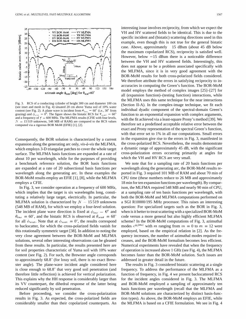
Fig. 3. RCS of a conducting cylinder of height 300 cm and diameter 100 cm(see inset and mesh in Fig. 4) situated 20 cm above Yuma soil of 10% watercontent (see Fig. 2). A plane wave is incident from� = 60� (i.e., 30� fromgrazing) and� = 0�. The figure shows the bistatic RCS for� = 60�
and a frequency off = 600 MHz. The MLFMA results (CFIE with four levels,N = 15 519 unknowns, 548 MB of RAM) are compared to the RCS valuescomputed via a rigorous BOR MoM (EFIE) [1], [2].
Consequently, the BOR solution is characterized by a currentexpansion along the generating arc only,vis-à-visthe MLFMA,which employs 3-D triangular patches to cover the whole targetsurface. The MLFMA basis functions are expanded at a rate ofabout 10 per wavelength, while for the purposes of providinga benchmark reference solution, the BOR basis functionsare expanded at a rate of 20 subsectional basis functions perwavelength along the generating arc. In these examples theBOR-MoM results employ an EFIE [1], [8], while the MLFMAemploys a CFIE.
In Fig. 3, we consider operation at a frequency of 600 MHz,which implies that the target is six wavelengths long, consti-tuting a relatively large target, electrically. In particular, theMLFMA solution is characterized by 15 519 unknowns(548 MB of RAM), for which we employ a four-level solution.The incident plane wave direction is fixed at and
60 , and the bistatic RCS is observed at 60for all . Note that at 0 , the results correspondto backscatter, for which the cross-polarized fields vanish forthis rotationally symmetric target [38]. In addition to noting thevery close agreement between the BOR-MoM and MLFMAsolutions, several other interesting observations can be gleanedfrom these results. In particular, the results presented here arefor soil properties characteristic of Yuma soil with 10% watercontent (see Fig. 2). For such, the Brewster angle correspondsto approximately 68.8(for lossy soil, there is no exact Brew-ster angle). The plane-wave incident angle considered hereis close enough to 68.8that very good soil penetration (andtherefore little reflection) is achieved for vertical polarization.This explains why the HH response is considerably larger thanits VV counterpart, the dihedral response of the latter beingreduced significantly by soil penetration.
Before proceeding, we consider the cross-polarizationresults in Fig. 3. As expected, the cross-polarized fields areconsiderably smaller than their copolarized counterparts. An
interesting issue involves reciprocity, from which we expect theVH and HV scattered fields to be identical. This is due to thespecific incident and (bistatic) scattering directions used in thisexample, even though this is not true for the general bistaticcase. Above, approximately15 dBsm (about 45 dB belowthe maximum copolarized RCS), reciprocity is satisfied well.However, below 15 dBsm there is a noticeable differencebetween the VH and HV scattered fields. Interestingly, thisdoes not appear to be a problem associated specifically withthe MLFMA, since it is in very good agreement with theBOR-MoM results for both cross-polarized fields considered.We therefore attribute the errors in satisfying reciprocity to in-accuracies in computing the Green’s function. The BOR-MoMmodel employs the method of complex images [25]–[27] forall (expansion function)–(testing function) interactions, whilethe MLFMA uses this same technique for the near interactions(Section II-A). In the complex-image technique, we fit eachindividual dyadic component of the spectral-domain Green’sfunction to an exponential expansion with complex arguments,with the fit achieved via a least-square Prony’s method [39]. Wetherefore set a predefined acceptable relative error between theexact and Prony representation of the spectral Green’s function,with that error set to 1% in all our computations. Small errorsin the expansion give rise to the errors in Fig. 3, manifested inthe cross-polarized RCS. Nevertheless, the results demonstratea dynamic range of approximately 45 dB, with the significantcross-polarization errors occurring primarily at angles forwhich the VH and HV RCS are very small.
We note that for a sampling rate of 20 basis functions perwavelength along the generating arc, the BOR-MoM results re-ported in Fig. 3 required 101 MB of RAM and about 70 min ofCPU time (these numbers reduce to 26 MB and approximately18 min for ten expansion functions per wavelength). By compar-ison, the MLFMA required 548 MB and nearly 90 min of CPU,at a sampling rate of ten basis functions per wavelength, withboth the BOR-MoM and MLFMA computations performed ona SGI R10000/195 MHz processor. This raises an interestingquestion: For specialized targets such as the BOR in Fig. 3,when is it better to treat scattering with a specialized BOR-MoMcode versus a more general but also highly efficient MLFMAscheme? In the BOR-MoM computations of Fig. 3, azimuthalmodes with ranging from 0 to 12 wereemployed, based on the empirical relation in [2]. As the fre-quency increases, the number of azimuthal modes required in-creases, and the BOR-MoM formalism becomes less efficient.Numerical experiments have revealed that when the frequencyof operation is increased above 1 GHz (see Fig. 4), the MLFMAbecomes faster than the BOR-MoM solution. Such issues areaddressed in greater detail in the future.
The results in Fig. 3 considered bistatic scattering at a singlefrequency. To address the performance of the MLFMA as afunction of frequency, in Fig. 4 we present backscattered RCSfor the incident angles considered in Fig. 3. The MLFMAand BOR-MoM employed a sampling of approximately tenbasis functions per wavelength (recall that the MLFMA andBOR-MoM solutions are characterized by distinct basis-func-tion types). As above, the BOR-MoM employs an EFIE, whilethe MLFMA is based on a CFIE formulation. We see in Fig. 4

1568 IEEE TRANSACTIONS ON GEOSCIENCE AND REMOTE SENSING, VOL. 38, NO. 4, JULY 2000
Fig. 4. As in Fig. 3, but plotting themonostaticRCS as a function offrequency. The discretization was fixed to about�10, for both the MLFMAand the body-of-revolution MoM. Atf = 1000 MHz the MLFMA usedN =
42 873 unknowns, five levels, and a total of 1.57 GB of RAM.
Fig. 5. Bistatic RCS of a model UXO (cylinder with hemispherical endcap)of length 153 cm and diameter 40.6 cm (see inset). The model UXO is buriedin Yuma soil of 5% water content (see Fig. 2) with the target symmetry axis intheyz-plane, at an angle of 30� relative to thez-axis and the nose down at adepthz = �217.5 cm. The RCS is plotted for varying� at a fixed angle� = 60� and a frequency of 600 MHz (N = 10 653 unknowns, see meshin Fig. 6), assuming a plane wave incident at� = � 90� (in theyz-plane)and� = 60�. Results from an MoM (using EFIE), FMM (using EFIE), andMLFMA (using CFIE and four levels) code are compared.
that the agreement between the MLFMA and BOR-MoMis excellent, for all frequencies considered. Results are onlyshown for copolarization, the cross-polarized fields vanishingin backscatter, as discussed above. To get a feel for the com-plexity, at 300 MHz the MLFMA required 161 MB of RAMand 20 min of CPU (3936 unknowns, three levels), whileat 1 GHz, these numbers are 1.57 GB and 227 min (42 873unknowns, five levels), where all computations were run on asingle SGI R10000/195 MHz processor.
B. Buried Unexploded Ordnance
In our next example we consider the ordnance-like target insetin Fig. 5, with the soil characterized by 5% water content (seeFig. 2). We compare results from the MLFMA, computed witha four-level CFIE, to results computed by the MoM and FMM,
Fig. 6. Required RAM and overall CPU time (on SGI R10000/195 MHz)for bistatic RCS calculations as in Fig. 5 (polarimetric RCS matrix for 1800scattering angles), for the frequency range 100–1000 MHz (corresponding toN = 309–28 539 unknowns) using MoM (with LUD), FMM, and MLFMA.The CPU time for the MoM solution forf > 600 MHz (N > 10 653) has beenextrapolated.
the latter two calculated using an EFIE. Note that, although theUXO target is rotationally symmetric, the target-(half space)composite in Fig. 5 is not, and therefore cannot be modeledwith the BOR-MoM software. Consequently, both the MoMand FMM computations employ the same triangular-patch basisfunctions as the MLFMA model. Using the coordinate systemshown inset in Fig. 5, the plane wave is incident at 90and 60 , and the bistatic fields are observed at60 and all . Due to bisectional symmetry, the cross-polar-ized fields should vanish at 90 . From Fig. 5, we seethat the three solutions are in good agreement, for all bistaticangles considered. We also note that, with Figs. 3 and 4 forcomparison, the scattering of such a buried ordnance is quitesmall at the frequency (600 MHz) considered, underscoring thedifficulty of radar-based sensing of such targets. However, in asynthetic aperture radar (SAR) mode [37], the addition of signa-tures from multiple positions along the SAR aperture may pro-vide a sufficient signature in the image for target detection. TheMLFMA will be used in the future to perform such phenomeno-logical studies as a function of target type, soil type, systembandwidth, aperture length, target orientation, and depressionangle. Such a comprehensive set of data is difficult to acquireexperimentally. The computations in Fig. 5 are characterized by10 653 unknowns (see Fig. 6 for RAM and CPU requirements).
Such phenomenological studies have motivated developmentof the MLFMA model, and it is therefore of interest to assessthe CPU and RAM requirements of this technique versusthe other algorithms presented in Fig. 5, namely, the MoMand FMM. In Fig. 6, we present the CPU and RAM require-ments for bistatic results as in Fig. 5, covering the frequencyrange 100–1000 MHz (corresponding to 309–28 539unknowns). As expected [17]–[20], the MLFMA requires orderO( lg ) RAM and CPU, while for the FMM these parametersare approximately order O( ). The slight undulations in theRAM/CPU complexity of the single-stage FMM are caused bya suboptimal clustering employed in our implementation of theFMM [28], [29]. We have found in general that the half-space
GENGet al.: MULTILEVEL FAST-MULTIPOLE ALGORITHM 1569
(a)
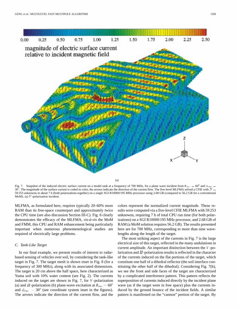
Fig. 7. Snapshot of the induced electric surface current on a model tank at a frequency of 700 MHz, for a plane wave incident from� = 60� and� =
30�. The magnitude of the surface current is coded in color, the arrows indicate the direction of the current flow. The five-level MLFMA solved a CFIE withN =
59 253 unknowns in about 7 h (both polarizations together) on a single SGI R10000/195 MHz processor using 2.68 GB (compared to 56.2 GB for a conventionalMoM). (a) V -polarization incident.
MLFMA, as formulated here, requires typically 20–60% moreRAM than its free-space counterpart and approximately twicethe CPU time (see also discussion Section III-C). Fig. 6 clearlydemonstrates the efficacy of the MLFMA,vis-à-visthe MoMand FMM, this CPU and RAM enhancement being particularlyimportant when numerous phenomenological studies arerequired of electrically large problems.
C. Tank-Like Target
In our final example, we present results of interest to radar-based sensing of vehicles over soil, by considering the tank-liketarget in Fig. 7. The target mesh is shown inset in Fig. 8 (for afrequency of 300 MHz), along with its associated dimensions.The target is 20 cm above the half space, here characterized asYuma soil with 10% water content (see Fig. 2). The currentsinduced on the target are shown in Fig. 7, for-polarization(a) and -polarization (b) plane-wave excitation at 60and 30 (see coordinate system inset in the figures).The arrows indicate the direction of the current flow, and the
colors represent the normalized current magnitude. These re-sults were computed via a five-level CFIE MLFMA with 59 253unknowns, requiring 7 h of total CPU run time (for both polar-izations) on a SGI R10000/195 MHz processor, and 2.68 GB ofRAM (a MoM solution requires 56.2 GB). The results presentedhere are for 700 MHz, corresponding to more than nine wave-lengths along the length of the target.
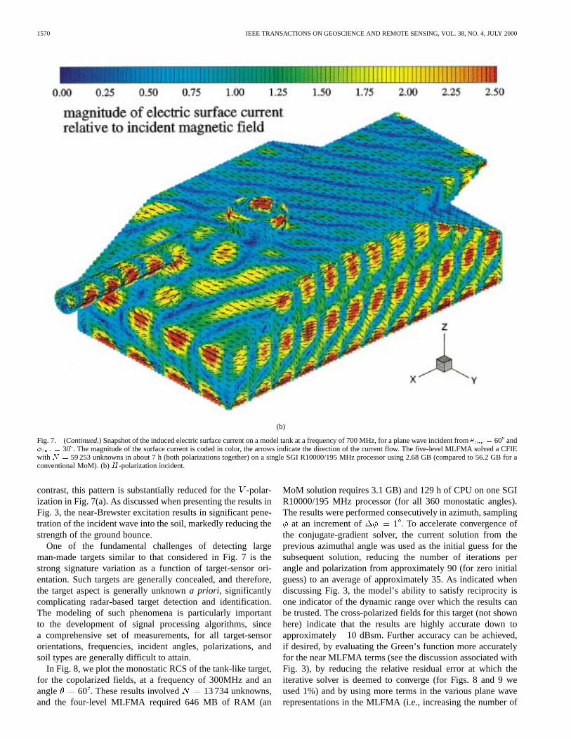
The most striking aspect of the currents in Fig. 7 is the largeelectrical size of this target, reflected in the many undulations incurrent amplitude. An important distinction between the-po-larization and -polarization results is reflected in the characterof the currents induced on the flat portions of the target, whichconstitute one half of a dihedral reflector (the soil interface con-stituting the other half of the dihedral). Considering Fig. 7(b),we see the front and side faces of the target are characterizedby a complicated interference pattern. This pattern reflects thesuperposition of currents induced directly by the incident planewave (as if the target were in free space) plus the currents in-duced by the ground bounce of the incident fields. A similarpattern is manifested on the “cannon” portion of the target. By
1570 IEEE TRANSACTIONS ON GEOSCIENCE AND REMOTE SENSING, VOL. 38, NO. 4, JULY 2000
(b)
Fig. 7. (Continued.) Snapshot of the induced electric surface current on a model tank at a frequency of 700 MHz, for a plane wave incident from� = 60� and� = 30�. The magnitude of the surface current is coded in color, the arrows indicate the direction of the current flow. The five-level MLFMA solved a CFIEwith N = 59 253 unknowns in about 7 h (both polarizations together) on a single SGI R10000/195 MHz processor using 2.68 GB (compared to 56.2 GB for aconventional MoM). (b)H-polarization incident.
contrast, this pattern is substantially reduced for the-polar-ization in Fig. 7(a). As discussed when presenting the results inFig. 3, the near-Brewster excitation results in significant pene-tration of the incident wave into the soil, markedly reducing thestrength of the ground bounce.
One of the fundamental challenges of detecting largeman-made targets similar to that considered in Fig. 7 is thestrong signature variation as a function of target-sensor ori-entation. Such targets are generally concealed, and therefore,the target aspect is generally unknowna priori, significantlycomplicating radar-based target detection and identification.The modeling of such phenomena is particularly importantto the development of signal processing algorithms, sincea comprehensive set of measurements, for all target-sensororientations, frequencies, incident angles, polarizations, andsoil types are generally difficult to attain.
In Fig. 8, we plot the monostatic RCS of the tank-like target,for the copolarized fields, at a frequency of 300MHz and anangle 60 . These results involved 13 734 unknowns,and the four-level MLFMA required 646 MB of RAM (an
MoM solution requires 3.1 GB) and 129 h of CPU on one SGIR10000/195 MHz processor (for all 360 monostatic angles).The results were performed consecutively in azimuth, sampling
at an increment of 1 . To accelerate convergence ofthe conjugate-gradient solver, the current solution from theprevious azimuthal angle was used as the initial guess for thesubsequent solution, reducing the number of iterations perangle and polarization from approximately 90 (for zero initialguess) to an average of approximately 35. As indicated whendiscussing Fig. 3, the model’s ability to satisfy reciprocity isone indicator of the dynamic range over which the results canbe trusted. The cross-polarized fields for this target (not shownhere) indicate that the results are highly accurate down toapproximately 10 dBsm. Further accuracy can be achieved,if desired, by evaluating the Green’s function more accuratelyfor the near MLFMA terms (see the discussion associated withFig. 3), by reducing the relative residual error at which theiterative solver is deemed to converge (for Figs. 8 and 9 weused 1%) and by using more terms in the various plane waverepresentations in the MLFMA (i.e., increasing the number of

GENGet al.: MULTILEVEL FAST-MULTIPOLE ALGORITHM 1571
Fig. 8. Radar cross section (here we only plot VV and HH) of a model tankwith N = 13 734 unknowns (see inset) situated above Yuma soil of 10% watercontent (see Fig. 2) at a frequency of 300 MHz.MonostaticRCS is plottedfor � = 60� (30� from grazing) and varying azimuth angles�. The four-levelMLFMA required a total of 646 MB of RAM (compared to 3.1 GB for aconventional MoM) and approximately 129 h of CPU time (on a single SGIR10000/195 MHz processor) for 360 monostatic angles.
Fig. 9. As in Fig. 8, but for a frequency of 700 MHz andN = 59 253unknowns (the mesh in Fig. 8 was refined). The five-level MLFMA required2.68 GB of RAM (compared to 56.2 GB for a conventional MoM solution)and 1022 h of total CPU time (on a single SGI R10000/195 MHz processor)for 720 monostatic angles.
terms in the addition theorem expansion beyond the requiredfor an error less than 1%, which has been applied for all
examples presented here) [17]–[20].In Fig. 9, we again consider the monostatic RCS of the
tank-like target, now computed at a frequency of 700 MHz.For these results, the azimuthal angle was sampled at a rateof 0.5 , to accurately capture the faster variation of theRCS at higher frequencies. For these computations the targetwas characterized by 59 253 unknowns, and the five-levelMLFMA required 2.68 GB of RAM. As in Fig. 8, we consider
60 . The computation of the full-polarimetric RCS (i.e.,VV, VH, HV, and HH), at 720 different angles, required 1022hours of total CPU time on a single SGI R10000/195 MHzprocessor. The RAM and CPU requirements (compared tothe 300 MHz case) are consistent with the theoretical com-plexity of O( lg ), when noting that the number of angles
in the 700 MHz calculation was doubled. As expected, relativeto the 300 MHz example of Fig. 8, the RCS results are charac-terized by substantially faster variation with azimuthal angle.
IV. CONCLUSIONS
An extension of the MLFMA has been presented for the anal-ysis of electromagnetic scattering from electrically large perfectconductors situated in the presence of a half space. The structureof the half-space MLFMA is similar in many ways to its free-space counterpart [17]–[20]. In particular, we exploit propertiesof the free space Green’s function to compute far (expansionfunction)–(testing function) interactions cumulatively throughuse of a multi-level clustering procedure [17]–[20]. Within thecontext of nonnearby cluster computations, interaction with thehalf space is accounted for approximately via polarization-de-pendent images located at real spatial locations. Hence, the firstescalation in complexity of the half-space MLFMA relative tothe free-space version is the introduction of image clusters, lo-cated in real space. In addition, the near interactions in the half-space MLFMA are treated via a rigorous analysis of the dyadicGreen’s function, here computed via the method of complex im-ages [25]–[27]. We have found such a rigorous analysis of thenear interactions essential for generating accurate results.
The MLFMA was calibrated by considering a specialproblem applicable to a MoM solution tailored to a BOR. Thisprovides a good test, because the BOR-MoM solution is nu-merically rigorous, and because the BOR-MoM and MLFMAsolutions employ distinct basis functions. The agreementbetween the MLFMA and BOR-MoM results was excellent,for all examples considered. Results were also presented fora UXO embedded in a lossy half space. For that problem theaccuracy of the MLFMA was favorably compared with MoMand FMM solutions. Moreover, CPU and RAM comparisonsclearly demonstrated the efficacy of the MLFMA technique,vis-à-visthe MoM and FMM. The final example considered atank-like target, for which several results were presented.
The results for scattering from the tank-like target wereinsightful, while also demonstrating that, for such a large target,the memory requirements of the MLFMA are substantiallysmaller than those of the MoM. However, these results alsoclearly demonstrate that significant work is still required on thedevelopment of modeling algorithms for wideband, multi-as-pect scattering from such targets. In particular, we notedthat the multi-aspect computations in Figs. 8 and 9 requiredsubstantial CPU (although much less than would be requiredusing a MoM model), and in practice, we would likely alsorequire data over a wide frequency range. These observationspoint to directions for future research. The half-space MLFMArepresents a numerically rigorous analysis of Maxwell’s equa-tions, within the context of the Green’s-function approximation(for far interactions) discussed previously. Consequently, wecan use the MLFMA results at high frequencies (such as inFig. 9) to examine the accuracy of approximate, asymptoticsolutions. The MLFMA can then be used to fill the frequencygap for which the MoM is intractable and for which asymptoticsolutions are inappropriate. In addition, all results presentedhere were run on a single processor. It is of interest to develop a
1572 IEEE TRANSACTIONS ON GEOSCIENCE AND REMOTE SENSING, VOL. 38, NO. 4, JULY 2000
scaleable, parallel version of the half-space MLFMA. Finally,in all MLFMA results, we have employed the RWG trian-gular-patch basis functions [7]. These basis functions are quitegeneral, but for electrically large problems, they result in a verysignificant number of unknowns. Researchers have, within thecontext of MoM, developed hybrid techniques that combinesubsectional basis functions with asymptotic traveling- waveand edge-diffraction basis functions [40]. The use of suchbasis functions substantially reduces the number of unknowns,reducing the problem size. It is of interest to incorporate suchtechniques into the MLFMA framework.
REFERENCES
[1] S. Vitebskiy, K. Sturgess, and L. Carin, “Short-pulse plane-wave scat-tering from buried perfectly conducting bodies of revolution,”IEEETrans. Antennas Propagat., vol. 44, pp. 143–151, Feb. 1996.
[2] N. Geng and L. Carin, “Wideband electromagnetic scattering from a di-electric BOR buried in a layered lossy, dispersive medium,”IEEE Trans.Antennas Propagat., vol. 47, pp. 610–619, Apr. 1999.
[3] N. Geng, M. Ressler, and L. Carin, “Wideband VHF scattering from atrihedral reflector situated above a lossy dispersive half space,” , to bepublished.
[4] J. M. Bourgeois and G. S. Smith, “A fully three-dimensional simula-tion of a ground-penetrating radar: FDTD theory compared with exper-iment,” IEEE Trans. Geosci. Remote Sensing, vol. 34, pp. 36–44, Jan.1996.
[5] , “A complete electromagnetic simulation of the separated-aperturesensor for detecting buried land mines,”IEEE Trans. Antennas Prop-agat., vol. 46, pp. 1419–1426, Oct. 1998.
[6] H. S. Chang and K. K. Mei, “Scattering of electromagnetic waves byburied and partly buried bodies of revolution,”IEEE Trans. Geosci. Re-mote Sensing, vol. GE-23, pp. 596–605, 1985.
[7] S. M. Rao, D. R. Wilton, and A. W. Glisson, “Electromagnetic scatteringfrom surfaces of arbitrary shape,”IEEE Trans. Antennas Propagat., vol.30, pp. 409–418, May 1982.
[8] K. A. Michalski and D. Zheng, “Electromagnetic scattering and radia-tion by surfaces of arbitrary shape in layered media, Parts I and II,”IEEETrans. Antennas Propagat., vol. 38, pp. 335–352, Mar. 1990.
[9] A. F. Peterson, S. L. Ray, and R. Mittra,Computational Methods forElectromagnetics. Piscataway, NJ: IEEE Press, 1998.
[10] J. M. Jin,The Finite Element Method in Electromagnetics. New York,NY: Wiley, 1993.
[11] A. Taflove, Computational Electromagnetics—The Finite-DifferenceTime-Domain Method. Boston, MA: Artech House, 1995.
[12] T. Dogaru and L. Carin, “Application of multi-resolution time-domainto two-dimensional electromagnetic scattering problems,” , submittedfor publication.
[13] A. Taflove, Ed.,Advances in Computational Electromagnetics—The Fi-nite-Difference Time-Domain Method. Norwood, MA: Artech House,1998.
[14] R. Coifman, V. Rokhlin, and S. Wandzura, “The fast multipole methodfor the wave equation: A pedestrian prescription,”IEEE Antennas Prop-agat. Mag., vol. 35, pp. 7–12, June 1993.
[15] J. M. Song and W. C. Chew, “Fast multipole method solution using para-metric geometry,”Microw. Opt. Technol. Lett., vol. 7, pp. 760–765, Nov.1994.
[16] A. Brandt, “Multilevel computations of integral transforms and particleinteractions with oscillatory kernels,”Comput. Phys. Commun., vol. 65,pp. 24–38, 1991.
[17] J. M. Song and W. C. Chew, “Multilevel fast multipole algorithmfor solving combined field integral equations of electromagneticscattering,”Microw. Opt. Technol. Lett., vol. 10, pp. 14–19, Sept. 1995.
[18] J. M. Song, C. C. Lu, W. C. Chew, and S. W. Lee, “Fast Illinois solvercode (FISC),”IEEE Trans. Antennas Propagat. Mag., vol. 40, pp. 27–33,June 1998.
[19] J. M. Song, C. C. Lu, and W. C. Chew, “Multilevel fast multipole al-gorithm for electromagnetic scattering by large complex objects,”IEEETrans. Antennas Propagat., vol. 45, pp. 1488–1493, Oct. 1997.
[20] X. Q. Sheng, J. M. Jin, J. Song, W. C. Chew, and C. C. Lu, “Solutionof combined-field integral equation using multilevel fast multipole al-gorithm for scattering by homogeneous bodies,”IEEE Trans. AntennasPropagat., vol. 46, pp. 1718–1726, Nov. 1998.
[21] M. Abramowitz and I. A. Stegun,Handbook of Mathematical Func-tions. New York: Dover, 1970.
[22] L. Gürel and M. I. Aksun, “Electromagnetic scattering solution of con-ducting strips in layered media using the fast multipole method,”IEEEMicrowave Guided Wave Lett., vol. 6, pp. 277–279, Aug. 1996.
[23] J. S. Zhao, W. C. Chew, C. C. Lu, E. Michielssen, and J. Song, “Thin-stratified medium fast-multipole algorithm for solving microstrip struc-tures,” IEEE Trans. Microw. Theory Tech., vol. 46, pp. 395–403, Apr.1998.
[24] Y. Rahmat-Samii, R. Mittra, and P. Parhami, “Evaluation of Sommerfeldintegralsor lossy half-space problems,”Electromagnetics, vol. 1, no. 1,pp. 1–28, 1981.
[25] J. J. Yang, Y. L. Chow, and D. G. Fang, “Discrete complex images of athree-dimensional dipole above and within a lossy ground,”Proc. Inst.Elect. Eng. H, vol. 138, pp. 319–326, Aug. 1991.
[26] R. M. Shubair and Y. L. Chow, “A simple and accurate complex imageinterpretation of vertical antennas present in contiguous dielectric half-spaces,”IEEE Trans. Antennas Propagat., vol. 41, pp. 806–812, June1993.
[27] M. I. Aksun, “A robust approach for the derivation of closed-formGreen’s functions,”Trans. Microw. Theory Tech., vol. 44, pp. 651–658,May 1996.
[28] N. Geng, A. Sullivan, and L. Carin, “Fast multipole method for scatteringfrom 3D PEC targets situated in a half-space environment,”Microw. Opt.Technol. Lett., vol. 21, pp. 399–405, June 1999.
[29] , “Fast multipole method for scattering from an arbitrary PEC targetabove or buried in a lossy half space,” , to be published.
[30] I. V. Lindell, Methods for Electromagnetic Field Analysis. Piscataway,NJ: IEEE Press, 1995.
[31] D. R. Wilton, S. M. Rao, A. W. Glisson, D. H. Schaubert, O. M.Al-Bundak, and C. M. Butler, “Potential integrals for uniform andlinear source distributions on polygonal and polyhedral domains,”IEEE Trans. Antennas Propagat., vol. 32, pp. 276–281, Mar. 1984.
[32] R. E. Hodges and Y. Rahmat-Samii, “The evaluation of MFIE integralswith the use of vector triangle basis functions,”Microw. Opt. Technol.Lett., vol. 14, pp. 9–14, Jan. 1997.
[33] A. D. McLaren, “Optimal numerical integration on a sphere,”Math.Comput., vol. 17, pp. 361–383, 1963.
[34] T. K. Sarkar and E. Arvas, “On a class of finite step iterative methods(conjugate directions) for the solution of an operator equation arisingin electromagnetics,”IEEE Trans. Antennas Propagat., vol. GE-33, pp.1058–1066, Oct. 1985.
[35] Y. Saad,Iterative Methods for Sparse Linear Systems. Boston, MA:PWS, 1996.
[36] N. M. Nachtigal, S. C. Reddy, and L. N. Trefethen, “How fast are non-symmetric matrix iterations?,”SIAM J. Matrix Anal. Appl., vol. 13, pp.778–795, July 1992.
[37] S. Vitebskiy, L. Carin, M. A. Ressler, and F. H. Le, “Ultra-wideband,short-pulse ground-penetrating radar: Simulation and measurement,”IEEE Trans. Geosci. Remote Sensing, vol. 35, pp. 762–772, May 1997.
[38] L. Carin, R. Kapoor, and C. E. Baum, “Polarimetric SAR imaging ofburied landmines,” , to be published.
[39] M. L. Van Blaricum and R. Mittra, “A technique for extracting the polesand residues of a system directly from its transient response,”IEEETrans. Antennas Propagat., vol. 23, pp. 777–781, Nov. 1975.
[40] A. Sullivan and L. Carin, “A hybrid technique combining the momentmethod with physical optics and uniform asymptotics for scattering from2D cylinders,”Microw. Opt. Technol. Lett., vol. 21, pp. 117–121, Apr.1999.
Norbert Geng (S’91–M’96) was on born May 14, 1965 in Lauchringen, Ger-many. He received the Dipl.-Ing. and Dr.-Ing. degrees in electrical engineeringfrom the University of Karlsruhe, Germany, in 1991 and 1996, respectively.
From 1991 to 1996, he was with the Institute for Microwaves and Electronics,University of Karlsruhe, working on full-wave propagation modeling for radiocommunications systems. From 1997 to 1998, he was with the Department ofElectrical and Computer Engineering, Duke University, Durham, NC, as a Vis-iting Postdoctoral Researcher. From 1998 to 1999, he was with the Universityof Karlsruhe. His research at both of these universities focused on numericaltechniques in computational electromagnetics for planar-stratified media. SinceJanuary 2000, he has been with SIEMENS Corporate Technology, Munich, Ger-many, as a Research Scientist on the design of broadband wireless communica-tions systems.
Dr. Geng received the Mannesmann Innovation Award in 1997 for his Ph.D.dissertation on this subject.

GENGet al.: MULTILEVEL FAST-MULTIPOLE ALGORITHM 1573
Anders Sullivan (M’93) was born on August 9, 1963, in Staten Island, NY. Hereceived the B.S. and M.S. degrees in aerospace engineering from the GeorgiaInstitute of Technology, Atlanta, GA, in 1985 and 1987, respectively, and thePh.D. degree in electromagnetics from Polytechnic University, Brooklyn, NY,in 1997.
From 1988 through May 1998, he was with the Air Force Research Lab, EglinAir Force Base, FL. From June 1998 to September 1999, he was with the Elec-trical Engineering Department, Duke University, Durham, NC, as a ResearchAssociate. Since September 1999, he has been with the Army Research Lab,Adelphi, MD. His current research interests include modeling complex targetsand short-pulse scattering.
Dr. Sullivan is a member of the Tau Beta Pi and Sigma Gamma Tau honorsocieties.
Lawrence Carin (SM’96) was born on March 25, 1963 in Washington, DC. Hereceived the B.S., M.S., and Ph.D. degrees in electrical engineering from theUniversity of Maryland, College Park, in 1985, 1986, and 1989, respectively.
In 1989, he joined the Electrical Engineering Department, Polytechnic Uni-versity, Brooklyn, NY, as an Assistant Professor, and became an Associate Pro-fessor in 1994. Since September 1995, he has been with the Electrical Engi-neering Department, Duke University, Durham, NC, where he is an AssociateProfessor. He is the Principal Investigator on a Multidisciplinary University Re-search Initiative (MURI) on demining. His current research interests includeshort-pulse scattering, subsurface sensing, and wave-based signal processing.
Dr. Carin is currently an Associate Editor of the IEEE TRANSACTIONS ON
ANTENNAS AND PROPAGATION. He is a member of Tau Beta Pi and Eta KappaNu.