multihead pinspotter - duro dyne · ing quality with minimum maintenance ... conjunction with this...
TRANSCRIPT

OWNER’SMANUAL
MULTIHEADPINSPOTTER
Multihead
MH
50
7Part #:3903039031
MACHINERY DIVISION

Page # 2
TABLE OF CONTENTS Appendix 25Auto Shift Service Guide 7Carriage Solenoid Assembly 26Initial Adjustments 3Introduction 2Flow Chart 6Maintenance 4-5Operation 4Parts Listing 28Service Index 9-24Set-Up 2Theory of Operation 5Weld Quality Symptoms 8Weld Transformer Modifications 27
INTRODUCTION
The new MH507 represents the finest production-line Pinspotter available today. Backed by Duro Dyne’s years of pinspotting experi-ence the MH507 Multi Head system will provide maximum fasten-ing quality with minimum maintenance
The carriage design eliminates the need for stopping the material for installation of fasteners. Combined with welded clip pins; the carriage ensures a quality product at production speeds of up to 25 ft per minute
The solid state components, proven on thousands of machines, are centrally located to make preventive maintenance easy. All compo-nents are easily reached through simple access panels.
This manual is designed to be your guide to keeping your MH507 operating at peak performance for years to come.
IMPORTANT: Always follow manufacturer’s recommendations for proper safety and handling proce dures, for all materials used in conjunction with this machine as outlined in Safety Data Sheet (SDS) for each product
MH507 SETUP 1) a) FGMH 507 Version 208-230 VAC, 3 Phase, 60 Amp minimum circuit protection. Circuit protection must be a High Magnetic type circuit breaker or slow blow type fuses. (Due to the inherent inrush current produced by this machine when welding Duro Dyne recommends
using the next size larger current capacity wire over code when possible.) Connect 3 Phase to 60 Amp Disconnect Box. Connect Control Console to a 120 VAC power supply. Control Box is internally fused for 3 Amps
b) FGMH 507 Version 480 VAC, 3 Phase, 30 Amp minimum circuit protections. Circuit protection must be a High Magnetic type circuit breaker or slow blow type fuses. (Due to the inherent inrush current produced by this machine when welding Duro Dyne recommends using the next larger current capacity wire over code when possible). Connect the 3 Phase to 30 Amp Disconnect Box. Connect Control Console to a 120 Vac power supply. Control Box is internally fused for 3 Amps
2) Locate the holes on the side of the MH507 Frame and bolt the control console support bracket using the supplied bolts.
3) Place the control console on the bracket and connect it to a source of11OV AC power, or wire a 110 VAC source to terminals 33 (neutral) and 32 (hot) inside of the control console.
4) Connect the air line to the regulator.
5) Adjust the regulator pressure to 100 psi
6) Repeat steps 7 through 10 for all five vibrator bowls.
7) Place a Bowl and Vibrator Assembly in position on its mounting plate.
8) Position the bowl so there is a slight space between the bowl and the feed track, (1/8"- 1/4"). This is to minimize noise. (Make sure to re-torque Allen Bolt to 25 ft/lbs.)
9) Plug the vibrator power plug into its receptacle on the rear plate of the machine.
Your MH507 is now ready for initial adjustments.

Page # 3
MH507 INITIAL ADJUSTMENTS1) Push the High Voltage Disconnect Switch to the "ON" position. Turn on the air.2) Turn the MH507 control console power switch "ON" the light will go on.3) Turn the weld switch to "OFF'' the weld power light will go off.4) Turn the carriage switch to "OFF" the carriage light will go off.5) Turn all head switches on the MH507 control console to the “ON" position.
6) Cycle the unit observing which heads come down and whether their movement is syn-chronized. (All heads should come down together.) If one or more heads are slow or fast, loosen the nut on the quick exhaust adjustable muffler and turn the screw until the head is in sync with the others; clockwise to slow down, counter clockwise to speed up.
NOTE: All heads are synchronized at the factory. However, as air components are "broken in," slight adjustment may be needed. Therefore, head speed should be checked.
Repeat steps 7 through 11 for all five bowls.7) Add clip pins to vibrator bowl (hopper).8) Turn the vibrator switch # 1 on the vibrator control Panel to the "ON" position.9) With the feed track empty, Turn Vibrator control until the hopper begins to vibrate.
10) Adjust the vibrator speed control #1 on the vibrator control panel so that the clip pins climb the spiral track inside the vibrator bowl without vibrating off.
11) When the clip pins fill the track up to the sensor assembly, the vibrator will automati-cally shut off.
12) If your unit does not have a carriage system, skip to the MH507 Operation Section otherwise proceed to Step 13.
13) Turn the carriage switch to "ON" the carriage light will go on.
14) Cycle the unit observing the carriage movement. The carriage must move smoothly and evenly with no binding. (Wand switch must be in down position. Carriage won’t continue to walk if wand switch is up.)
SEE APPENDIX II
NOTE: The carriage is factory adjusted to a production line speed of approximately 25 FPM
Machines installed in a Vicon or Mestek coil line have a wand switch for controlling the car-riage return.
15) For the carriage return adjustment:A) Turn power to control console to offB) Standing in front of the machine, pull the carriage toward you. C) Turn power to control console on.D) Carriage will return to the "Home Position." Adjust Flow Controls on the carriage
cylinder until the carriage returns smoothly.
The MH507 is now ready for operation

Page # 4
MH507 OPERATION1) Be sure the high voltage disconnect switch is in the "ON'' Position air is at 100 PSI, and
the MH507 control console is plugged in or wired and on. 2) Be sure the MH507 control console power switch and the weld power switch are in the
''ON" position, both lights will be lit.
NOTE: For the Carriage models make sure the carriage switch is in the “ON" position.
3) Place the head switches in the “ON” position on the MH507 control console for the heads you desire to use.
4) Put the vibrator switches on the vibrator control panel for the heads you desire to use
in the “ON” position
5) Never actuate the unit with the weld switch in the “ON” position and no metal over the weld tip severe pitting on the lower weld tip will occur if this is done.
6) For maximum weld quality, make sure the sheet metal rides over and is in flat contact with the lower weld tips.
7) The weld time and dwell time settings control the weld quality of all heads of the MH507 Pinspotter. The weld time is the length of time the transformers are on, a fraction of a second is all the time generally needed for a quality weld. Excess time wastes energy and burns pins. (If the pin glows red up to the washer the weld time is too long.) The weld timer should be set for the minimum time required for a strong weld, the dwell time is the length of time the upper welding tip remains in down position. The dwell time should always be longer than then weld time to allow the weld to cool.
8) It is suggested that you pretest a run using a small sample of steel and liner you intend to use in final liner production. Different thickness of metal and or liner may require slight adjustments in weld and dwell time. Only change timer settings when material change results in poor weld quality or performance.
MAINTENANCE1) To prolong the weld tip life and improve weld quality, it is imperative that the weld tips are
always kept clean. For best results, use a solvent to remove adhesive from tips; a wire brush to remove any galvanize deposits; and a fine emory cloth to smooth tip surfaces.
2) When the lower weld tip becomes worn in one area, loosen the locking cap screw and rotate the point of wear away from the point of contact of the tip. Additional lower weld tips and plates can be ordered from your local distributor.
3) Depending on usage and maintenance, upper welding tips will have to be periodically replaced. Replacement upper weld tips can be ordered from your local distributor. To replace the upper weld tip loosen the locking cap screw and remove the weld tip. Insert new tip with undercut running parallel to frame, and then lock in place. Cycle the machine to check feeding.
4) If feeding is erratic, readjust the upper weld tip height by loosening the lock nut and then turn-ing the weld cylinder shaft clockwise to raise the tip,Lock the tip in place with locking nut.
Continued...

Page # 5
5) Do not lubricate the air supply. Do not put lubricant in regulator assembly.
6) Grease the pillow block bearings every 3-6 months through grease fittings on the top of the bearing.
NOTE: Never apply any type of oil on brake bar surfaces. Should oil or grease accidentally get on the bar remove the lubricant immediately to protect the brake shoes. Failure to do this will render the carriage inoperable.
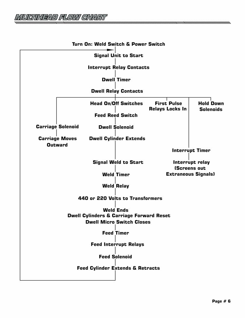
THEORY OF OPERATION MH507 When the MH507 is given a signal to start (either by pushing the center red button on the control console or by jumping terminals 35 and 36 through an automatic controller) the sig-nal flows through the Interrupt Relay contacts and activates the Dwell Timer. The Dwell Timer energizes the Dwell Relay which:
A) Activates the Carriage/Brake Solenoid, locking the brakes and moving the carriage forward.
B) Energizes the First Pulse Relay locking it in.
C) Deactivates both Feed Interrupt Relays preventing pin feeding during the dwell cycle.
D) Passes signal to the head switches at the top of the MH507 control console.
E) Energizes the Interrupt Timer which activates the Interrupt Relay preventing another sig-nal reaching the Dwell Timer for as long as the Interrupt Timer is set.
The head switches in the control console (when they are in “ON” position) pass the 24 volt signal through the Feed Reed Switches of their respective heads activating their Dwell Sole-noid and driving the weld tip down. As the weld tip moves down a signal flows through the Weld Switch on the MH507 Control Console and activates the Weld Timer. The Weld Timer energizes the Weld Relay which passes 220 volts to the solid state Weld Relay which activates the 220 volts (or 480 volts if unit is wired for 440 volts) to the welding transformers, powering the transformers for as long as the weld timer is set.
After the Dwell Timer cycles, the Dwell Relay deactivates causing:
A) All dwell cylinders to retract.
B) The carriage brakes return and
C) Re-energizes the Feed Interrupt Relays. When each Dwell Cylinder is fully retracted it closes the Dwell Micro Switch passing a signal to the Feed Timer. The feed timer in turn passes a signal through the Feed interrupt relays activating the Feed Solenoid causing the Feed Cylinder to extend. This breaks the feed reed switch preventing a dwell cycle during feed. At the end of the feed timer cycle, the Feed Cylinder retracts closing the Feed Reed Switch and readying the unit for another cycle.
The reed switch on each feed cylinder and the micro switch on top of each of the head as-semblies acts as interlocks preventing the feed and dwell cylinders extending at same time.
NOTE: If your unit is not a carriage unit, the theory of operation is the same except the dwell relay does not activate the carriage brake solenoid.
Page # 6
MULTIHEAD FLOW CHART
Turn On: Weld Switch & Power Switch
Signal Unit to Start
Interrupt Relay Contacts
Dwell Timer
Dwell Relay Contacts
Head On/Off Switches
Feed Reed Switch
Dwell Solenoid
Dwell Cylinder Extends
Signal Weld to Start
Weld Timer
Weld Relay
440 or 220 Volts to Transformers
Weld EndsDwell Cylinders & Carriage Forward Reset
Dwell Micro Switch Closes
Feed Timer
Feed Interrupt Relays
Feed Solenoid
Feed Cylinder Extends & Retracts
Carriage Solenoid
Carriage MovesOutward
Interrupt Timer
Interrupt relay(Screens out
Extraneous Signals)
Hold DownSolenoids
First PulseRelays Locks In
Page # 7
SIMPLIFIED STEP BY STEP
PROCEDURE
EASY TO USE
WHAT TO DOBEFORE YOU BEGINTROUBLESHOOTING
Duro Dyne has called upon its many years of resistance welding experience in designing the MH507 Pinspotter, Your unit has been rigorously factory tested and inspected to provide you with many years of dependable service
MH507 AUTO SHIFT SERVICE GUIDE
The Service Guide supplements your Owner's Manual, and is de-signed to help you quickly and systematically isolate and identify the correct Pinspotter problems. Troubleshooting procedures are grouped according to symptoms in three functional areas; Feed and Dwell Assemblies, Vibrator and Weld Quality.
To use The Guide properly, you simply:
1) IDENTIFY SYMPTOM(S) IN THE INDEX ON PAGE 7.2) TURN TO THE APPROPRIATE GUIDE SECTION.3) FOLLOW THE TEST PROCEDURES IN THAT SECTION IN
SEQUENCE.
With the help of this Guide you should be able to correct most problems that occur. However, if you feel that a particular prob-lem is beyond your capability by all means, contact your Duro Dyne distributor, your Duro Dyne Tech Service or the nearest Duro Dyne facility.
CONSULT THE MANUALBefore you refer to this Service Guide, you should consult your Owner's Manual and re check all "Set Up", "initial Adjustment", "Operation" and "Maintenance" procedures.
INSPECT THE UNITIf the problem still persists, the next step is a MH507 visual inspection. Turn off the electricity that is, disconnect your MH507 from its power supply - and carefully check both the Control Console and the machine for loose, broken or discon-nected wires. Also check the air circuit for leaky air connec-tions or cut hoses.
POSITION IT PROPERLYThe location of your MH507 in relation to the power supply and the size of its power connection can greatly affect the weld quality. For maximum efficiency position your unit as close as possible to the power supply and use #6 (or bigger) wire for the connection to the breaker box.
Page # 8
HOW TO IDENTIFY WELD QUALITY SYMPTOMS
By WELD we mean that the transformers are energized, sending a pulse of electricity through the clip pin, causing it to begin to fuse to the sheet metal.
To properly troubleshoot weld quality problems, you must first pinpoint the symptom by test welding clip pins to bare sheet metal. The symptom will then show up in one of four categories:
1) Pins weld to bare metal but not on lined work.2) Pins weld to bare metal but can easily be removed.3) Pins weld to bare metal but remain on weld tip as it retracts.4) Pins do not weld at all.Before performing any troubleshooting steps in the weld Quality Section, always check:
1) Air Pressure for minimum 100PSI during usage of unit2) Input voltage for minimum 220V (or 480V on those units so wired) 3) Weld and Dwell Timer for correct settings - See Owner's Manual "Operation" section.4) Upper and Lower Weld Tips for extreme wear5) Foreign Material in the Air Supply (i.e. Oil or Moisture).
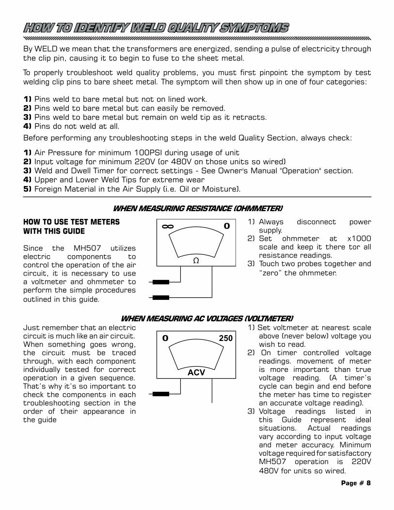
WHEN MEASURING RESISTANCE (OHMMETER)
WHEN MEASURING AC VOLTAGES (VOLTMETER)
1) Always disconnect power supply.
2) Set ohmmeter at x1000 scale and keep it there tor all resistance readings.
3) Touch two probes together and “zero” the ohmmeter.
HOW TO USE TEST METERS WITH THIS GUIDE Since the MH507 utilizes electric components to control the operation of the air circuit, it is necessary to use a voltmeter and ohmmeter to perform the simple procedures outlined in this guide.
Just remember that an electric circuit is much like an air circuit. When something goes wrong, the circuit must be traced through, with each component individually tested for correct operation in a given sequence. That’s why it’s so important to check the components in each troubleshooting section in the order of their appearance in the guide
1) Set voltmeter at nearest scale above (never below) voltage you wish to read.
2) On timer controlled voltage readings. movement of meter is more important than true voltage reading. (A timer’s cycle can begin and end before the meter has time to register an accurate voltage reading).
3) Voltage readings listed in this Guide represent ideal situations. Actual readings vary according to input voltage and meter accuracy. Minimum voltage required for satisfactory MH507 operation is 220V 480V for units so wired.
Page # 9
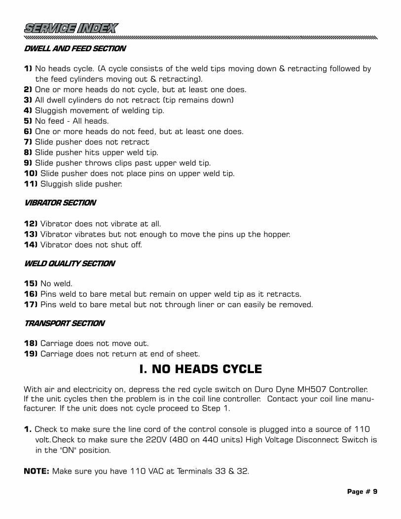
SERVICE INDEXDWELL AND FEED SECTION
1) No heads cycle. (A cycle consists of the weld tips moving down & retracting followed by the feed cylinders moving out & retracting).
2) One or more heads do not cycle, but at least one does.3) All dwell cylinders do not retract (tip remains down)4) Sluggish movement of welding tip.5) No feed - All heads.6) One or more heads do not feed, but at least one does.7) Slide pusher does not retract8) Slide pusher hits upper weld tip.9) Slide pusher throws clips past upper weld tip.10) Slide pusher does not place pins on upper weld tip.11) Sluggish slide pusher.
VIBRATOR SECTION
12) Vibrator does not vibrate at all.13) Vibrator vibrates but not enough to move the pins up the hopper.14) Vibrator does not shut off.
WELD QUALITY SECTION
15) No weld.16) Pins weld to bare metal but remain on upper weld tip as it retracts.17) Pins weld to bare metal but not through liner or can easily be removed.
TRANSPORT SECTION
18) Carriage does not move out.19) Carriage does not return at end of sheet.
I. NO HEADS CYCLE
With air and electricity on, depress the red cycle switch on Duro Dyne MH507 Controller. If the unit cycles then the problem is in the coil line controller. Contact your coil line manu-facturer. If the unit does not cycle proceed to Step 1.
1. Check to make sure the line cord of the control console is plugged into a source of 110 volt.Check to make sure the 220V (480 on 440 units) High Voltage Disconnect Switch is in the "ON" position.
NOTE: Make sure you have 110 VAC at Terminals 33 & 32.
Page # 10
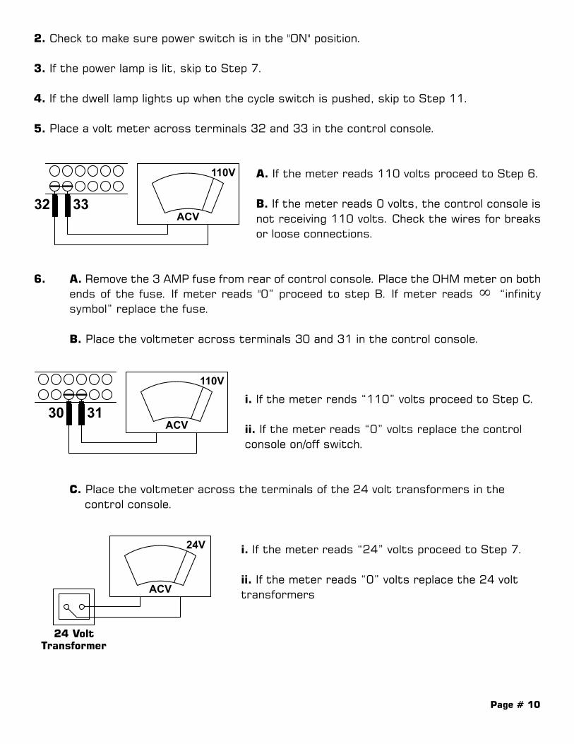
2. Check to make sure power switch is in the "ON" position.
3. If the power lamp is lit, skip to Step 7.
4. If the dwell lamp lights up when the cycle switch is pushed, skip to Step 11.
5. Place a volt meter across terminals 32 and 33 in the control console.
A. If the meter reads 110 volts proceed to Step 6.
B. If the meter reads 0 volts, the control console is not receiving 110 volts. Check the wires for breaks or loose connections.
6. A. Remove the 3 AMP fuse from rear of control console. Place the OHM meter on both ends of the fuse. If meter reads "0” proceed to step B. If meter reads ∞ “infinity symbol” replace the fuse.
B. Place the voltmeter across terminals 30 and 31 in the control console.
i. If the meter rends “110” volts proceed to Step C.
ii. If the meter reads “0” volts replace the control console on/off switch.
C. Place the voltmeter across the terminals of the 24 volt transformers in the control console.
i. If the meter reads “24” volts proceed to Step 7.
ii. If the meter reads “0” volts replace the 24 volt transformers
Page # 11
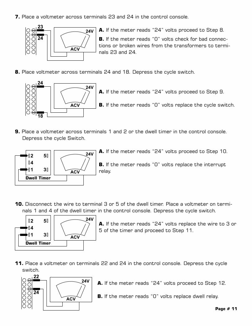
7. Place a voltmeter across terminals 23 and 24 in the control console.
A. If the meter reads “24” volts proceed to Step 8.
B. If the meter reads “0” volts check for bad connec-tions or broken wires from the transformers to termi-nals 23 and 24.
8. Place voltmeter across terminals 24 and 18. Depress the cycle switch.
A. If the meter reads “24” volts proceed to Step 9.
B. If the meter reads “0” volts replace the cycle switch.
9. Place a voltmeter across terminals 1 and 2 or the dwell timer in the control console. Depress the cycle Switch.
A. If the meter reads “24” volts proceed to Step 10.
B. If the meter reads “0” volts replace the interrupt relay.
10. Disconnect the wire to terminal 3 or 5 of the dwell timer. Place a voltmeter on termi-nals 1 and 4 of the dwell timer in the control console. Depress the cycle switch.
A. If the meter reads “24” volts replace the wire to 3 or5 of the timer and proceed to Step 11.
11. Place a voltmeter on terminals 22 and 24 in the control console. Depress the cycle switch.
A. If the meter reads “24” volts proceed to Step 12.
B. If the meter reads “0” volts replace dwell relay.
24V
ACV
23
24
24V
ACV
24
18
24V
ACV
241 3
5
24V
ACV
241 3
5
24V
ACV
22
24
24V
ACV
24
16
Dwell Timer
Dwell Timer
24V
ACV
23
24
24V
ACV
24
18
24V
ACV
241 3
5
24V
ACV
241 3
5
24V
ACV
22
24
24V
ACV
24
16
Dwell Timer
Dwell Timer
24V
ACV
23
24
24V
ACV
24
18
24V
ACV
241 3
5
24V
ACV
241 3
5
24V
ACV
22
24
24V
ACV
24
16
Dwell Timer
Dwell Timer
24V
ACV
23
24
24V
ACV
24
18
24V
ACV
241 3
5
24V
ACV
241 3
5
24V
ACV
22
24
24V
ACV
24
16
Dwell Timer
Dwell Timer
24V
ACV
23
24
24V
ACV
24
18
24V
ACV
241 3
5
24V
ACV
241 3
5
24V
ACV
22
24
24V
ACV
24
16
Dwell Timer
Dwell Timer
Page # 12
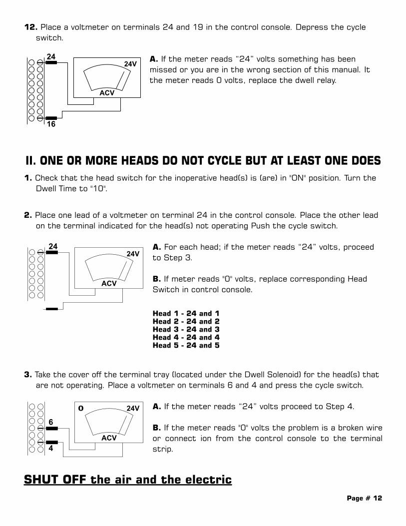
12. Place a voltmeter on terminals 24 and 19 in the control console. Depress the cycle switch.
A. If the meter reads “24” volts something has been missed or you are in the wrong section of this manual. It the meter reads 0 volts, replace the dwell relay.
II. ONE OR MORE HEADS DO NOT CYCLE BUT AT LEAST ONE DOES1. Check that the head switch for the inoperative head(s) is (are) in "ON" position. Turn the
Dwell Time to "10".
2. Place one lead of a voltmeter on terminal 24 in the control console. Place the other lead on the terminal indicated for the head(s) not operating Push the cycle switch.
A. For each head; if the meter reads “24” volts, proceed to Step 3.
B. If meter reads "0" volts, replace corresponding Head Switch in control console.
3. Take the cover off the terminal tray (located under the Dwell Solenoid) for the head(s) that are not operating. Place a voltmeter on terminals 6 and 4 and press the cycle switch.
A. If the meter reads “24” volts proceed to Step 4.
B. If the meter reads "0" volts the problem is a broken wire or connect ion from the control console to the terminal strip.
SHUT OFF the air and the electric
24V
ACV
23
24
24V
ACV
24
18
24V
ACV
241 3
5
24V
ACV
241 3
5
24V
ACV
22
24
24V
ACV
24
16
Dwell Timer
Dwell Timer
Head 1 - 24 and 1Head 2 - 24 and 2Head 3 - 24 and 3Head 4 - 24 and 4Head 5 - 24 and 5

Page # 13
4. Place all head switches in the "OFF" position. Place an ohm meter across terminals 4 and 5 in the terminal tray. Push the slide pusher (s) into the fully retracted position then extend the slide pusher(s) forward all the way.
A) If the meter reads "0" when the pusher is all the way back and ∞ “infinity symbol” when fully extended. Replace the dwell solenoid.
B) If the meter reads infinite when the pusher is retracted, loosen the set screws on the reed switch mounted on the feed cylinder and move back and forth until a “O" reading is obtained on the meter. Fail-ure to get a "0" reading indicates a bad reed switch and it must be replaced. If the meter reads "0" in both the extended and retracted positions, the reed switch must also be replaced.
III. ALL DWELL CYLINDERS DO NOT RETRACT(THE WELD TIP REMAINS DOWN)
1. Disconnect the potentiometer wires from terminals 5 and 3 on the dwell timer in the control console. Place a jumper wire across terminals 5 and 3 of the dwell timer. If nothing happens, proceed to Step 2. II the cylinder retracts, replace potentiometer.
2. Place a voltmeter across terminals 1 and 4 of the dwell timer.
A. If the meter reads “24” volts replace dwell timer.
B. If the meter reads “0” volts replace dwell relay.
IV. SLUGGISH MOVEMENT OF WELDING TIP
1. Check the Air Pressure Air pressure must be minimum 80 psi during cycle. If trouble persists Proceed to Step 2
2. Check for oil or water in lines. If oil or water is in lines, disconnect and blow out air lines. Remove and clean all exhaust
mufflers. Reconnect air lines. Cycle unit repeatedly to remove excess oil Reconnect ex-haust mufflers. If trouble persists proceed to Step 3.
3. Check Dwell Cylinder Shaft for Binding. The Shaft should be able to move freely. If trouble persists, proceed to Step 4.
4. Check for Air Leakage or restrictions. Replace cut or pinched air lines. If trouble persists, proceed to Step 5.
5. Replace the Dwell Solenoid.
24V
ACV
2
4
1 3
5
Dwell Timer
24V
ACV
24
10

Page # 14
V. ONE OR MORE HEADS DO NOT FEED BUT AT LEAST ONE DOESSHUT OFF AIR
1. Remove the terminal tray covers (located under the Dwell Solenoid) of the inoperative head(s). Place a voltmeter across terminals 2 and 3. Move the dwell cylinder up and down.
A. If the meter reads “0 volts when the head is all the way up and “24” volts when down proceed to step 2.
B. If the meter reads “24” volts in both positions replace the micro switch on the dwell cylinder.
C. If the meter reads "0" volts in both po-sitions check for a bad connection in the micro switch or the terminal tray If the connection is okay replace the micro switch.
2. Turn Air/Electric on. Place a voltmeter across the feed timer terminals 1 and 2 in the con-trol console. Cycle the unit.
A. If the meter reads “24” volts, proceed to Step 3.
B. If the meter reads "0" volts check for a loose con-nection or a broken wire.
3. Remove the wire from terminal 3 or 5 of the feed timer located in the control console of the defective head(s). Place the voltmeter across terminals 1 and 4 on the feed timer in the control console. Cycle the unit.
A. If the meter reads “24” volts replace the wire to 3 or 5 of the feed timer and proceed to Step 4.
B. If the meter reads "0" volts replace the feed timer.
24V
ACV3
2
24V
ACV
Weld Tip Up Weld Tip Down
24V
ACV
241 3
5
24V
ACV
241 3
5
Dwell Timer
Dwell Timer
24V
ACV
23
24V
ACV3
2
24V
ACV
Weld Tip Up Weld Tip Down
24V
ACV
241 3
5
24V
ACV
241 3
5
Dwell Timer
Dwell Timer
24V
ACV
23
24V
ACV3
2
24V
ACV
Weld Tip Up Weld Tip Down
24V
ACV
241 3
5
24V
ACV
241 3
5
Dwell Timer
Dwell Timer
24V
ACV
23
Page # 15
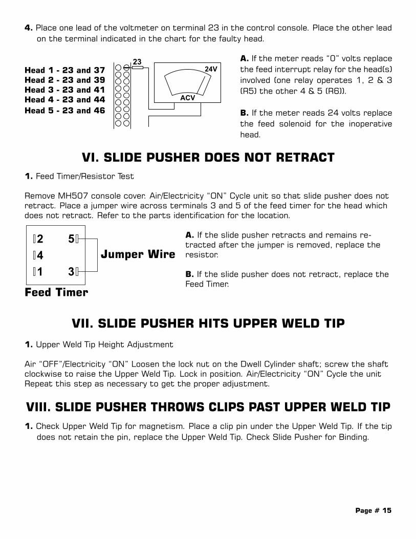
4. Place one lead of the voltmeter on terminal 23 in the control console. Place the other lead on the terminal indicated in the chart for the faulty head.
Head 1 - 23 and 37Head 2 - 23 and 39Head 3 - 23 and 41Head 4 - 23 and 44Head 5 - 23 and 46
VI. SLIDE PUSHER DOES NOT RETRACT1. Feed Timer/Resistor Test
Remove MH507 console cover. Air/Electricity “ON” Cycle unit so that slide pusher does not retract. Place a jumper wire across terminals 3 and 5 of the feed timer for the head which does not retract. Refer to the parts identification for the location.
A. If the slide pusher retracts and remains re-tracted after the jumper is removed, replace the resistor.
B. If the slide pusher does not retract, replace the Feed Timer.
VII. SLIDE PUSHER HITS UPPER WELD TIP
1. Upper Weld Tip Height Adjustment
Air “OFF”/Electricity “ON” Loosen the lock nut on the Dwell Cylinder shaft; screw the shaft clockwise to raise the Upper Weld Tip. Lock in position. Air/Electricity “ON” Cycle the unit Repeat this step as necessary to get the proper adjustment.
VIII. SLIDE PUSHER THROWS CLIPS PAST UPPER WELD TIP1. Check Upper Weld Tip for magnetism. Place a clip pin under the Upper Weld Tip. If the tip
does not retain the pin, replace the Upper Weld Tip. Check Slide Pusher for Binding.
24V
ACV3
2
24V
ACV
Weld Tip Up Weld Tip Down
24V
ACV
241 3
5
24V
ACV
241 3
5
Dwell Timer
Dwell Timer
24V
ACV
23 A. If the meter reads “0” volts replace the feed interrupt relay for the head(s) involved (one relay operates 1, 2 & 3 (R5) the other 4 & 5 (R6)).
B. If the meter reads 24 volts replace the feed solenoid for the inoperative head.
241 3
5
Feed Timer
Jumper Wire
Page # 16
IX. SLIDE PUSHER DOES NOT PLACE PINS ON UPPER WELD TIP1. Check for Binding. Air/Electricity “OFF”. Hold the Upper Weld Tip “UP”. Move the Slide Pusher into the ex-
tended position. Check that the Pusher is aligned with the Upper Weld Tip and that neither it nor the clip pins bind under the Upper Weld Tip. If trouble persists, proceed to Step 2.
2. Check Slide Pusher Pawl Air/Electricity OFF With the Slide Pusher in extended position, check that the pawl is free.
X. SLUGGISH SLIDE PUSHER1. Check Air Pressure Air pressure must be a minimum of 80 psi during usage. If trouble persists, proceed to
Step 2.
2. Check for oil or water in lines. If oil or water is in the air lines, disconnect and blow out all the air lines. Remove and
clean the exhaust mufflers reconnect the air lines. Cycle the unit repeatedly to remove oil. Reconnect the exhaust mufflers if the trouble persists, proceed to Step 3.
3. Check the Slide Pusher of the Feed Cylinder Shaft for Binding. Both should be able to move freely. If trouble persists, proceed to Step 4.
4. Replace the Feed Solenoid.
XI. VIBRATOR DOES NOT VIBRATE AT ALLNOTE: Remove the clip pins from the feed tract on all vibrator test procedures.
1. Perform Initial Check A. Air ON B. High Voltage Disconnect- ON- Fuses all okay C. Vibrator On/Off Switch ON D. The Vibrator Base Line Cord Plug is attached to the Vibrator Receptacle At the front of MH507 E. The Vibrator Speed Control is at the MAXIMUM Setting
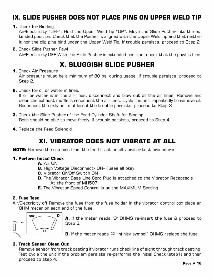
2. Fuse TestAir/Electricity off Remove the fuse from the fuse holder in the vibrator control box place an
OHM meter on each end of the fuse.
A. If the meter reads "O" OHMS re-insert the fuse & proceed to Step 3.
B. If the meter reads ∞”infinity symbol” OHMS replace the fuse.
3. Track Sensor Clean Out Remove sensor from track casting if vibrator runs check line of sight through track casting,
Test cycle the unit if the problem persists re-performs the initial Check (step1) and then proceed to step 4.
Page # 17
4. Vibrator sensor receive Board check
A. Remove non working vibrator take neighboring vibrator cord only and plug into non working vibrator head.
B. If this neighboring vibrator works vibrator that was removed is defective.C. If vibrator still does not work leave neighboring vibrator plugged in for test purposes.D. Remove cover from vibrator senor board receiver mounting box located on the back
of the head track casting.E. Locate term strip on receiver board and jump term C to term D (term strip marked
A through H left to right)F. If vibrator runs replace sensor. (Make sure procedure #3 was checked first)G. If vibrator still will not function jump term A to F on receiver board, if vibrator runs
replace receiver board if vibrator still does not run go to step 5
5. Vibrator Control Relay Check- mounted on back wall of transformer enclosure.
A. Using Volt Meter test term #3 and #4 of solid state relay for 24 VacB. If there is 0 volts, check wires for brakes. If there are no broken wires, go back
over step 4.C. If voltage is 24 Vac Led on solid state relay will be on.D. Check terminals 6 & 7 for 220V. If meter reads 220V, check terminals 1 & 2 on the
relay. If voltage reads 0V, relay is good.
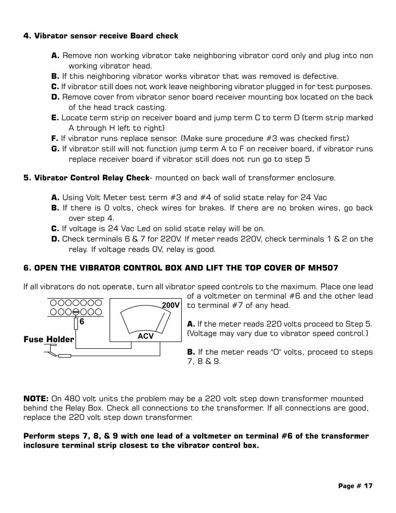
6. OPEN THE VIBRATOR CONTROL BOX AND LIFT THE TOP COVER OF MH507
If all vibrators do not operate, turn all vibrator speed controls to the maximum. Place one lead of a voltmeter on terminal #6 and the other lead to terminal #7 of any head.
A. If the meter reads 220 volts proceed to Step 5. (Voltage may vary due to vibrator speed control.)
B. If the meter reads "O" volts, proceed to steps 7, 8 & 9.
NOTE: On 480 volt units the problem may be a 220 volt step down transformer mounted behind the Relay Box. Check all connections to the transformer. If all connections are good, replace the 220 volt step down transformer.
Perform steps 7, 8, & 9 with one lead of a voltmeter on terminal #6 of the transformer inclosure terminal strip closest to the vibrator control box.
200V
ACV
6
Fuse Holder
200V
ACV
6
Fuse Holder
200V
ACV
6On/Off Switch
Page # 18
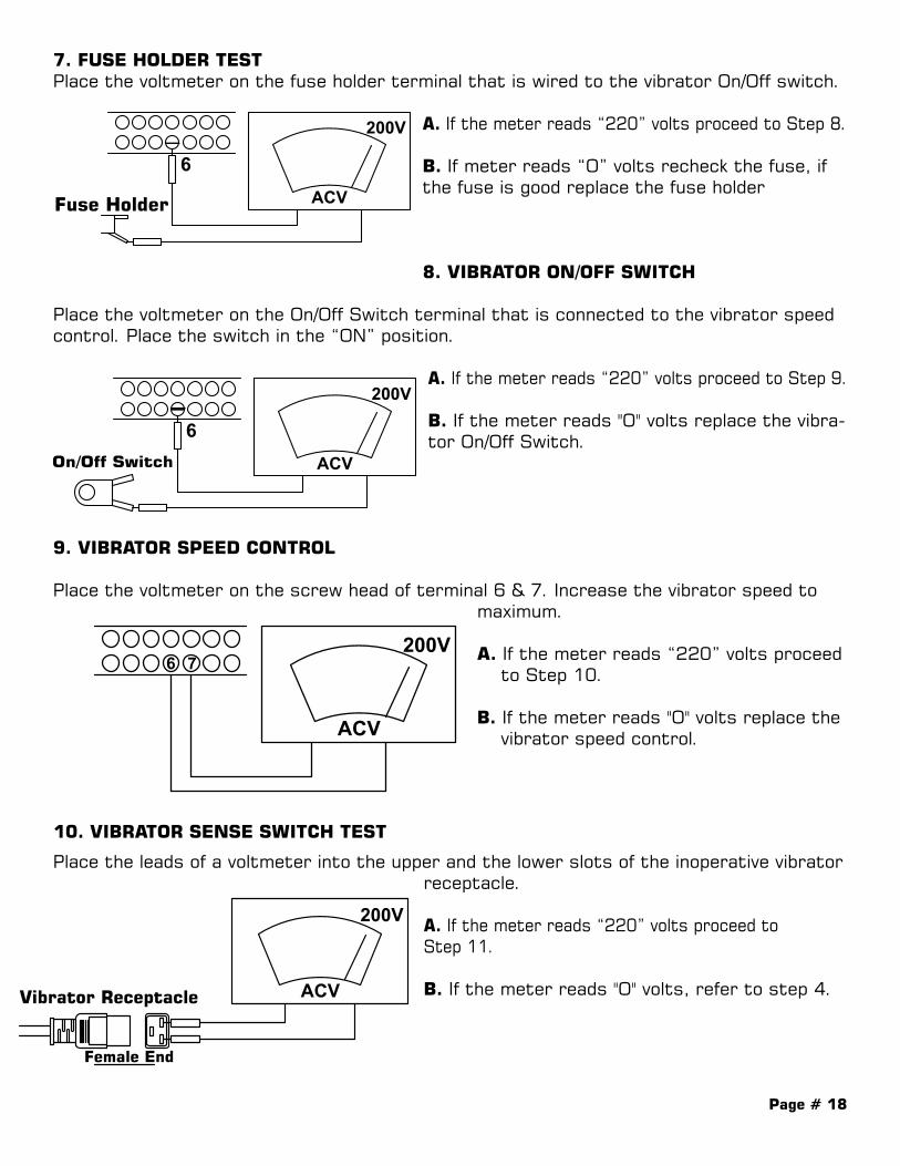
7. FUSE HOLDER TESTPlace the voltmeter on the fuse holder terminal that is wired to the vibrator On/Off switch.
A. If the meter reads “220” volts proceed to Step 8. B. If meter reads “O” volts recheck the fuse, if the fuse is good replace the fuse holder
8. VIBRATOR ON/OFF SWITCH
Place the voltmeter on the On/Off Switch terminal that is connected to the vibrator speed control. Place the switch in the “ON” position.
A. If the meter reads “220” volts proceed to Step 9.
B. If the meter reads "O'' volts replace the vibra-tor On/Off Switch.
9. VIBRATOR SPEED CONTROL Place the voltmeter on the screw head of terminal 6 & 7. Increase the vibrator speed to maximum.
A. If the meter reads “220” volts proceed to Step 10.
B. If the meter reads "O" volts replace the vibrator speed control.
10. VIBRATOR SENSE SWITCH TEST
Place the leads of a voltmeter into the upper and the lower slots of the inoperative vibrator receptacle.
A. If the meter reads “220” volts proceed to Step 11.
B. If the meter reads "O" volts, refer to step 4.
200V
ACV
6
Fuse Holder
200V
ACV
6
Fuse Holder
200V
ACV
6On/Off Switch
200V
ACV
6
Fuse Holder
200V
ACV
6
Fuse Holder
200V
ACV
6On/Off Switch
200V
ACV
6
200V
ACVVibrator Receptacle
Female End
Vibrator Plug
Male End
7
200V
ACV
6
200V
ACVVibrator Receptacle
Female End
Vibrator Plug
Male End
7

Page # 19
11. VIBRATOR TEST
Place the leads of an OHM meter on the vibrator plug prongs.
If the meter reads “∞” Resistance the problem is either a bad vibrator coil or a bad connection between the vibrator coil and the plug.
XII. VIBRATOR VIBRATES BUT NOT ENOUGH TO MOVE PINS UP HOPPER
1. CHECK THAT THE BOLT ATTACHING THE VIBRATOR BOWL TO THE BASE IS TORQUE TO 25 FP. If trouble persists proceed to Step 2.
2. VIBRATOR SPEED CONTROL TEST Remove the vibrator receptacle of the defective vibrator from the top panel of the MH507.
Set the voltmeter to the nearest scale above 200 Volts, Electricity on (Vibrator On/Off Switch On. Vibrator Base Line Cord plugged into the Vibrator Receptacle. The Feed Track empty of pins. Connect a voltmeter (as shown), across the Vibrator Power Receptacle contacts of the defective vibrator, and take AC voltage readings as you vary the Vibrator Speed Control of the defective vibrator.
A. If the meter reads as shown (from 90 V to 220 V Min.) the Vibrator Speed Control is OK; proceed to Step 3. B. If the meter does not show significant voltage change as the vibrator speed control is varied from high to low: replace the Vibrator Speed Control.
XIII. VIBRATOR DOES NOT SHUT OFF
Sensor and Receiver Board Check
Go to step 4 perform section A and D.A. Locate term strip remove wire from term C or term D.B. If vibrator stops sensor is defective.C. Remove wire from term F if vibrator stops Receiver Board is defective.D. If vibrator continues running replace vibrator control relay.
200V
ACV
6
200V
ACVVibrator Receptacle
Female End
Vibrator Plug
Male End
7
90V
ACV
200V
ACV
Vibrator Speed Vibrator SpeedMinimum Maximum
Vibrator Receptacle
Female End

Page # 20
XIV. NO WELD (TRANSFORMERS DO NOT GO ON)1. Check that the air is at a minimum of 100 psi.
2. Check that 220 volt (480 Volts on units so wired) High Voltage Disconnect Switch is on.
3. Check that the weld switch is in the "on" position.
4. A. Depress the cycle switch. If the weld lamp lights up skip to Step 8.
B. Turn all the head switches off, turn the weld "ON.” Turn the weld time to 10; dwell time to "0". Place one lead of a voltmeter on the ground bar Place the other end on any upper weld tip assembly. Cycle the unit. If the meter reads greater than "0"volts, you are in the wrong section of the manual. Go to (XVII) PINS WELD TO BARE METAL BUT NOT THROUGH LINER OR CAN EASILY BE REMOVED. If the meter reads "0" volts proceed to Step 5.
5. Place a 24 voltmeter across terminals 24 and 19 in the control console. Cycle the unit.
A. If the meter reads “24” volts proceed to step 6.
B. If the meter reads “0” volts the problem is a bad weldRelay, weld switch, or a broken connection to the weldSwitch from the relay socket to the weld switch.
6. Place a voltmeter across terminals 1 and 2 of the weld timer in the control console. Cycle the unit
A. If the meter reads “24” volts proceed to step 7.
B. If the meter reads “0” volts check for any loose con-nection or a broken wire between the weld switch and terminal 1 of the weld timer
C. If there are no broken wires, replace the weld switch.
7. Remove the wire from terminal 3 or 5 of the weld timer. Place a voltmeter across termi-nals 1 and 4 of the weld timer control console Cycle the unit
A. If the meter reads “24” volts replace the wire on the terminal 3 or 5 of the weld timer and proceed to step 8.
B. If the meter reads “0” volts replace the weld timer
24V
ACV
24
19
24V
ACV
241 3
5
Weld Timer
24V
ACV
241 3
5
Weld Timer
110V
ACV
24
21
110V
ACV
0
MercuryRelay
24V
ACV
24
19
24V
ACV
241 3
5
Weld Timer
24V
ACV
241 3
5
Weld Timer
110V
ACV
24
21
110V
ACV
0
MercuryRelay
24V
ACV
24
19
24V
ACV
241 3
5
Weld Timer
24V
ACV
241 3
5
Weld Timer
110V
ACV
24
21
110V
ACV
0
MercuryRelay

Page # 21
8. Set the weld timer to maximum, all heads switches “OFF”. Place a voltmeter across ter-minals 24 and 21 in the control console. Cycle the unit.
A. If the meter reads “24” volts proceed to step 9
B. If the metal reads “0” volts check for broken wires from terminals 24 or 21 to the weld relay
C. If the wires and connections are okay replace the weld relay.
9. With the weld timer set to maximum and the head switch “OFF”. Place a voltmeter across each Solid State Weld relay input (terminal 3&4) and cycle the unit
A. If the meter reads “24” volts on terminal 3 & 4, you have probably overlooked something in the previous testing
B. If the meter reads “0” on any or all relay inputs, the problem is a broken wire from ter-minal 24 or 21 to relay.
XV. PINS WELD TO BARE METAL BUT REMAIN ON UPPER WELD TIP AS IT RETRACTS
If the Clip Pin glows red up to the washer, decrease the Weld Time. The dwell time should always allow the weld to cool slightly before the weld tip retracts.
If the Clip Pin does not glow red up to the washer, increase the dwell and the weld time".
Refer to Owner's Manual: "Operation", steps 7 and 8.
XVI. PINS WELD TO BARE METAL BUT NOT THROUGH LINER
1. CHECK AIR PRESSURE. Air pressure must be a minimum of 80 psi during a cycle. If trouble persists, proceed to
Step 2.
2. CHECK FOR OIL OR WATER IN AIR LINES. If oil or water are in lines disconnect and blow out all air lines. Remove and clean the
exhaust mufflers. Reconnect the air lines. Cycle the unit repeatedly to remove the oil. Reconnect the exhaust mufflers. If trouble persists, proceed to Step 3.
3. CHECK DWELL CYLINDER SHAFT FOR BINDING. The shaft should be able to move freely. If trouble persists, proceed to Step 4.
24V
ACV
24
19
24V
ACV
241 3
5
Weld Timer
24V
ACV
241 3
5
Weld Timer
110V
ACV
24
21
110V
ACV
0
MercuryRelay
Page # 22
4. INCREASE WELD/DWELL TIMES Slightly increase both Weld and Dwell Timer settings. (Refer to MH507 Owner’s Manual
Operation steps 7 and 8.) The Upper Weld Tip should not begin to retract until the weld cycle is completed. If trouble persists proceed to Step
5. CHECK CLIP PIN POINTS The clip pin points must be sharp enough to penetrate the liner.
6. CHECK CARRIAGE MOVEMENT A. If the carriage does not move at all. Skip to Section VII- CARRIAGE DOES NOT MOVE OUT. B. If the carriage moves, check that it does not move faster or slower than the transfer
belts of the coil line. The carriage should not pull or hamper steel. Refer to.MH507 Own-er's Manual:” Initial Adjustments. Steps 12-15.
7. CHECK HEAD SPEEDS All heads should travel up and down at the same speed. If the heads are not sychronized,
refer to MH507 Owners’ Manual: Initial Adjustments. Step 6.
XVII. IF PINS WELD BUT ARE EASILY REMOVEDALWAYS INCREASE WELD AND DWELL TIME FIRST
NOTE: IF UNIT IS WIRED FOR 480 CHANGE ALL MENTION OF 220 TO 480 IN THE FOLLOWING STEPS
CHECK VOLTAGE
1. Open the High Voltage Disconnect Box. Check for proper voltage across all legs.
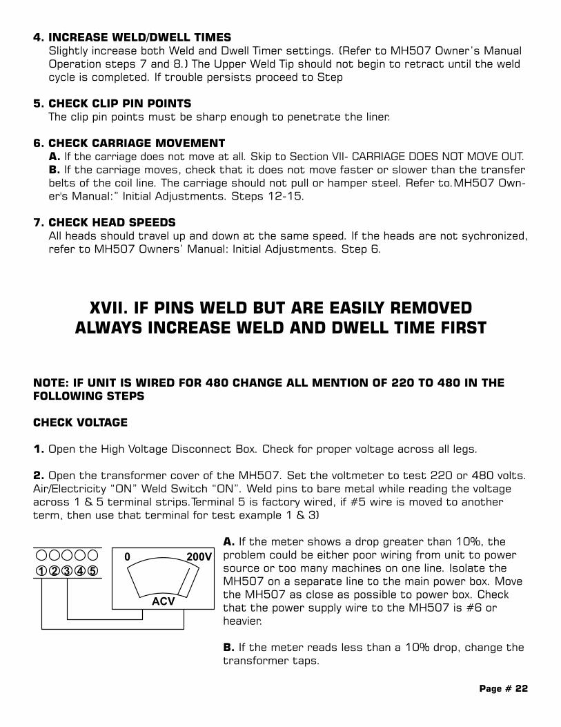
2. Open the transformer cover of the MH507. Set the voltmeter to test 220 or 480 volts. Air/Electricity “ON” Weld Switch “ON”. Weld pins to bare metal while reading the voltage across 1 & 5 terminal strips.Terminal 5 is factory wired, if #5 wire is moved to another term, then use that terminal for test example 1 & 3)
A. If the meter shows a drop greater than 10%, the problem could be either poor wiring from unit to power source or too many machines on one line. Isolate the MH507 on a separate line to the main power box. Move the MH507 as close as possible to power box. Check that the power supply wire to the MH507 is #6 or heavier.
B. If the meter reads less than a 10% drop, change the transformer taps.
200V
ACV
1 30
2 4 5

Page # 23
XVIII. CARRIAGE DOES NOT MOVE OUT
1. Check that the Carriage Switch on the MH507 Console is in the "ON" position.
2. Check that the Carriage Return Wand Switch is being depressed when a steel sheet is passing through the MH507 (When the switch is depressed, the carriage should move freely). If carriage will not move by hand with the wand switch depressed. Go to Section XIX.
3. Check for loose or broken wires in the control console on the small terminal strip on the back plate of the console
4. Check that the Carriage/Brake regulator gauges in the back of the lower tube are set to proper PSI (See Appendix II)
5. Check the Carriage for binding. The carriage should move freely with the air off.
6. With the Carriage Switch on the MH507 Console "ON", place a voltmeter between termi-nals 23 and 26 in the control console. Cycle the unit.
A. If the meter reads "24" volts, proceed to Step 7.
B. If the meter reads "O" volts, replace the Carriage Switch.
7. With the Carriage Switch on the MH507 Console "ON", place a voltmeter between termi-nals 1 and 4 of the Carriage Timer in the Control Console. Cycle the unit.
A. If the meter reads "24" volts, proceed to Step 8.
B. If the meter reads "O" volts, replace the Carriage Timer.
8. With the Carriage Switch "ON", place a voltmeter between terminals 24 and 34 in the Control Console. Cycle the unit.
A. If the meter reads "24" volts, replace the Carriage/Brake Solenoid
B. If the meter reads "O" volts, replace the Carriage Relay.
24V
ACV
28
24
24V
ACV
241 3
5
Carriage ClampDelay Timer
24V
ACV3424
24V
ACV
25
26
24V
ACV
43
23
24V
ACV
28
24
24V
ACV
241 3
5
Carriage ClampDelay Timer
24V
ACV3424
24V
ACV
25
26
24V
ACV
43
23
24V
ACV
28
24
24V
ACV
241 3
5
Carriage ClampDelay Timer
24V
ACV3424
24V
ACV
25
26
24V
ACV
43
23

Page # 24
XIX. CARRIAGE DOES NOT RETURN ORJERKS FORWARD AND THEN RETURNS
1. With power “OFF” check that the Carriage Return Flow Controls are not shut off.
2. Place an OHM meter between terminals 25 and 26 in the MH507 Control Console.
A. If the meter reads greater then 0 with the Wand Up and “O" with Wand depressed, proceed to Step 3.
B. If the meter reads other than above, replace the Wand Switch.
3. Place a voltmeter between terminals 23 and 43 in the MH507 Control Console.
A. If the meter reads "24" volts, replace the Carriage Return Solenoid.
B. If the meter reads "O" volts, replace the Carriage Return Relay.
24V
ACV
28
24
24V
ACV
241 3
5
Carriage ClampDelay Timer
24V
ACV3424
24V
ACV
25
26
24V
ACV
43
23
24V
ACV
28
24
24V
ACV
241 3
5
Carriage ClampDelay Timer
24V
ACV3424
24V
ACV
25
26
24V
ACV
43
23
Page # 25
APPENDIX I
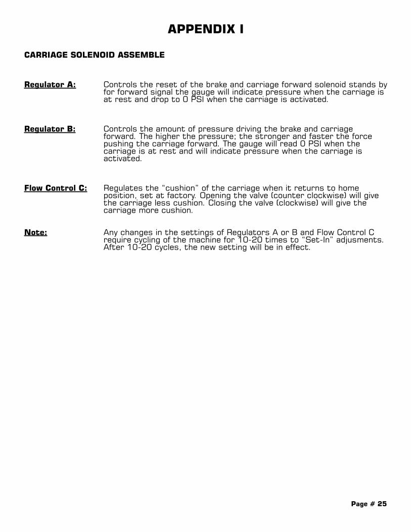
CARRIAGE SOLENOID ASSEMBLE
Regulator A: Controls the reset of the brake and carriage forward solenoid stands by for forward signal the gauge will indicate pressure when the carriage is at rest and drop to 0 PSI when the carriage is activated.
Regulator B: Controls the amount of pressure driving the brake and carriage forward. The higher the pressure; the stronger and faster the force pushing the carriage forward. The gauge will read 0 PSI when the carriage is at rest and will indicate pressure when the carriage is activated.
Flow Control C: Regulates the “cushion” of the carriage when it returns to home position, set at factory. Opening the valve (counter clockwise) will give the carriage less cushion. Closing the valve (clockwise) will give the carriage more cushion.
Note: Any changes in the settings of Regulators A or B and Flow Control C require cycling of the machine for 10-20 times to “Set-In” adjusments. After 10-20 cycles, the new setting will be in effect.

Pag
e #
26
CARRIA
GE
SO
LEN
OID
ASSEB
LY
INE
XH
AB
CYL
IN
EXH
EXH
GA
UG
ES
ET
GA
UG
ES
ET
TO R
UN
60 (R
EF)
35 (R
EF)
MU
FFLE
R
RE
GU
LATO
R-A
RE
GU
LATO
R-B
FLO
W C
ON
TRO
L-C
Page # 27
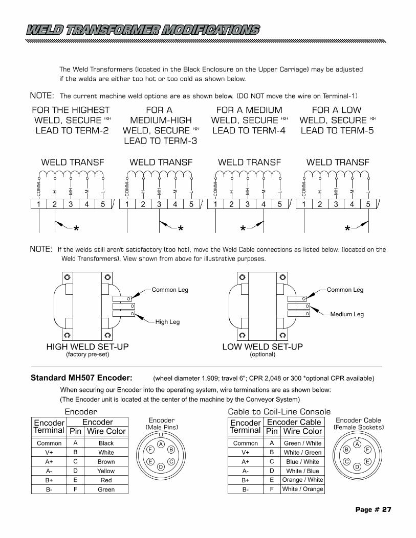
Weld Transformer Modifications:The Weld Transformers (located in the Black Enclosure on the Upper Carriage) may be adjusted if the welds are either too hot or too cold as shown below.
NOTE: The current machine weld options are as shown below. (DO NOT move the wire on Terminal-1)
4321
WELD TRANSF
FOR THE HIGHEST WELD, SECURE '*'LEAD TO TERM-2
5
CO
MM
MMHH L
4321
WELD TRANSF
FOR AMEDIUM-HIGH
WELD, SECURE '*'LEAD TO TERM-3
5
CO
MM
M L
4321
WELD TRANSF
FOR A MEDIUMWELD, SECURE '*'LEAD TO TERM-4
5C
OM
M
M L
NOTE: If the welds still aren't satisfactory (too hot), move the Weld Cable connections as listed below. (located on the Weld Transformers), View shown from above for illustrative purposes.
HIGH WELD SET-UP LOW WELD SET-UP
Common Leg
Medium Leg
Common Leg
High Leg
MHH MHH
(factory pre-set) (optional)
4321
WELD TRANSF
FOR A LOWWELD, SECURE '*'LEAD TO TERM-5
5
CO
MM
M LMHH
* * * *
Standard MH507 Encoder: (wheel diameter 1.909; travel 6"; CPR 2,048 or 300 *optional CPR available)
When securing our Encoder into the operating system, wire terminations are as shown below:(The Encoder unit is located at the center of the machine by the Conveyor System)
DC
B
E
AF
ABCDEF
PinGreen / WhiteWhite / GreenBlue / WhiteWhite / Blue
Orange / WhiteWhite / Orange
Wire ColorCommon
V+A+A-B+B-
EncoderTerminal
Encoder Cable
DE
F
C
AB
ABCDEF
PinBlackWhiteBrownYellowRed
Green
Wire ColorCommon
V+A+A-B+B-
EncoderTerminal
Encoder Encoder(Male Pins)
Encoder Cable(Female Sockets)
Encoder Cable to Coil-Line Console
WELD TRANSFORMER MODIFICATIONS
Page # 28
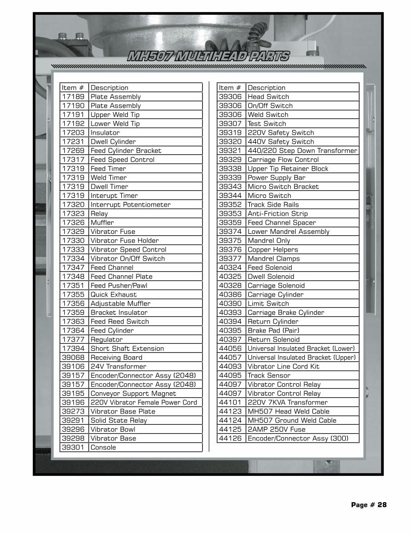
MH507 MULTIHEAD PARTS
Item # Description17189 Plate Assembly17190 Plate Assembly17191 Upper Weld Tip17192 Lower Weld Tip17203 Insulator17231 Dwell Cylinder17269 Feed Cylinder Bracket17317 Feed Speed Control17319 Feed Timer17319 Weld Timer17319 Dwell Timer17319 Interupt Timer17320 Interrupt Potentiometer17323 Relay17326 Muffler17329 Vibrator Fuse17330 Vibrator Fuse Holder17333 Vibrator Speed Control17334 Vibrator On/Off Switch17347 Feed Channel17348 Feed Channel Plate17351 Feed Pusher/Pawl17355 Quick Exhaust17356 Adjustable Muffler17359 Bracket Insulator17363 Feed Reed Switch17364 Feed Cylinder17377 Regulator17394 Short Shaft Extension39068 Receiving Board39106 24V Transformer39157 Encoder/Connector Assy (2048)39157 Encoder/Connector Assy (2048)39195 Conveyor Support Magnet39196 220V Vibrator Female Power Cord39273 Vibrator Base Plate39291 Solid State Relay39296 Vibrator Bowl39298 Vibrator Base39301 Console
Item # Description39306 Head Switch39306 On/Off Switch39306 Weld Switch39307 Test Switch39319 220V Safety Switch39320 440V Safety Switch39321 440/220 Step Down Transformer39329 Carriage Flow Control39338 Upper Tip Retainer Block39339 Power Supply Bar39343 Micro Switch Bracket39344 Micro Switch39352 Track Side Rails39353 Anti-Friction Strip39359 Feed Channel Spacer39374 Lower Mandrel Assembly39375 Mandrel Only39376 Copper Helpers39377 Mandrel Clamps40324 Feed Solenoid40325 Dwell Solenoid40328 Carriage Solenoid40386 Carriage Cylinder40390 Limit Switch40393 Carriage Brake Cylinder40394 Return Cylinder40395 Brake Pad (Pair)40397 Return Solenoid44056 Universal Insulated Bracket (Lower)44057 Universal Insulated Bracket (Upper)44093 Vibrator Line Cord Kit44095 Track Sensor44097 Vibrator Control Relay44097 Vibrator Control Relay44101 220V 7KVA Transformer44123 MH507 Head Weld Cable44124 MH507 Ground Weld Cable44125 2AMP 250V Fuse44126 Encoder/Connector Assy (300)

Page # 29
NOTES

Page # 30
NOTES

Page # 31
NOTES

Mu
ltihea
d
®
MACHINERY DIVISION© 2017 Duro Dyne CorporationPrinted in USA 8/11/2017BI060004
®
Please Visit Our Website
www.durodyne.comfor the most current product information.
Products that may also be of interest to you:
Duro Dyne East Division, Bay Shore, NY 631-249-9000 Fax: 631-249-8346Duro Dyne Midwest Division, Hamilton, OH 513-870-6000 Fax: 513-870-6005Duro Dyne West Division, Fontana, CA 562-926-1774 Fax: 562-926-5778Duro Dyne Canada, Lachine, Quebec, Canada 514-422-9760 Fax: 514-636-0328 www.durodyne.com E-mail: [email protected]