multigard 5000 gas sampling system
TRANSCRIPT

3103-1001 Rev. 0
MULTIGARD® 5000 GAS SAMPLING SYSTEM DOCUMENTATION PACKAGE
Description
Section Ultima X Series Gas Monitor, Product Information CD, P/N 10042446
1
MULTIGARD 5000 SYSTEM CONFIGURATION DATA
MultiGard System Configuration
User Configured Outputs Planning Matrix
2
MULTIGARD 5000 SYSTEM OPERATION AND MAINTENANCE
MANUAL
Custom Functions and Feature Descriptions
3103-1001 Rev. 0
3
SENSOR / ANALYZER MANUALS
Ultima® X Gas Series Gas Monitor, P/N 10036101
Ultima/Ultima X Series Controller and Calibrator, P/N 813379
ChemGard Manual P/N 10031540
4
MULTIGARD 5000 SYSTEM SUPPORT DOCUMENTS
Safe Handling of Compressed Gasses in the Laboratory and Plant
Matheson BR-11
Replacement Parts Form
Section 1
MULTIGARD® 5000 SYSTEM
CONFIGURATION DATA
Instrument Division 1-800-MSA-INST or FAX (724) 776-8783
MSA International (412) 967-3354 or FAX (412) 967-3451
In Canada 1-800-267-0672 or FAX (416) 663-5908
Manufactured by
MSA North America 1000 Craberry Woods Drive Cranberry Township, PA 16066
MSA CORPORATE CENTER
1000 Cranberry Woods Drive
Cranberry Township, Pennsylvania 16066
MultiGard® 5000
System Configuration Data
Contents
1. Custom System Definition
2. Factory Configured Parameters
3. User Configured Parameters
4. User Configured Outputs Planning Matrix - Option # 1
5. User Configured Outputs Planning Matrix - Option # 2

MultiGard Custom System Definition
System Serial Number:
H17-400913267-11-001 & H17-400913267-11-002
End User: Thermal Equipment Corp
Job Number: 400913267
ATO: A-MG5000-C-B-A-B-0-0-A-A-A-B-C
Model: Single 32
Processor Version: 3102-20 Rev 0
Display Version: 3102-21 Rev 0
System A System B
Calibration Gases Zero Instrument Air
Comb Propane .6% Span Value 20
CO CO 60 PPM
Nominal Sensor Flow Rate 3 SCFH +/- .5 SCFH
Minimum Sensor Flow Rate 2 SCFH +/- .5 SCFH
Minimum Sample Line Flow Rate 8 SCFH +/- .5 SCFH
UCO Option # 1 X Not Installed
(User Configured Outputs) Form C Relays
Solid State Outputs
UCO Option # 2 X Not Installed
(User Configured Outputs) Form C Relays
Solid State Outputs
System Drawings Drawing Number DSK3103- 1045
Notes:
System is configured for BACNet
WAN side admin IP is 192.168.1.110:8080
LAN 10.10.79.103 BACNet, Processor 10.10.79.102, Display 10.10.79.101, Router 10.10.79.1
Panelview Plus 7, V9.0

MultiGard Factory Configured Parameters
Sensor 1 Sensor 2 Sensor 3 Sensor 4
Sensor Type (5 characters max) Comb CO NA NA
Engineering Units %LEL PPM
Low Engineering Unit 0 0
High Engineering Unit 100 100
Analog Signal Interface Type Current Current
Analog Input Signal Maximum 20 20
Analog Input Signal Minimum 4 4
Warning Direction Increasing Increasing
Alarm Direction Increasing Increasing
Auto Standardize Disabled Disabled
ASTD Tolerance in EGU's, Low NA NA
ASTD Tolerance in EGU's, High NA NA
Synthetic Span Gas in Use No No
Combustible Sensor? Yes No
Warning & Alarm Limit in %LEL 60 NA
Purge Operation (comb. sensor) Yes No
Purge valve selection (none, Zero NA
zero,span1,span2)
Purge Set Point in %LEL 30 NA
Zero Span 1 Span 2 Sample Purge
Auto Standardize Duration NA NA NA NA
Auto Standardize Duration System B NA NA NA NA
Purge Duration (sec.) 30
Purge Duration, System B (sec.) NA
Manual Control of Span 1 Valve Yes
Manual Control of Span 2 Valve Yes
System B Control of Span 1 Valve NA
System B Control of Span 2 Valve NA
PIR Ready Enabled No
PIR Ready Enabled System B NA
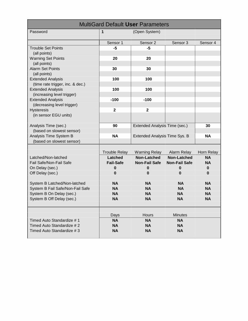
MultiGard Default User Parameters
Password 1 (Open System)
Sensor 1 Sensor 2 Sensor 3 Sensor 4
Trouble Set Points -5 -5
(all points)
Warning Set Points 20 20
(all points)
Alarm Set Points 30 30
(all points)
Extended Analysis 100 100
(time rate trigger, inc. & dec.)
Extended Analysis 100 100
(increasing level trigger)
Extended Analysis -100 -100
(decreasing level trigger)
Hysteresis 2 2
(in sensor EGU units)
Analysis Time (sec.) 90 Extended Analysis Time (sec.) 30
(based on slowest sensor)
Analysis Time System B NA Extended Analysis Time Sys. B NA
(based on slowest sensor)
Trouble Relay Warning Relay Alarm Relay Horn Relay
Latched/Non-latched Latched Non-Latched Non-Latched NA
Fail Safe/Non-Fail Safe Fail-Safe Non-Fail Safe Non-Fail Safe NA
On Delay (sec.) 0 0 0 0
Off Delay (sec.) 0 0 0 0
System B Latched/Non-latched NA NA NA NA
System B Fail Safe/Non-Fail Safe NA NA NA NA
System B On Delay (sec.) NA NA NA NA
System B Off Delay (sec.) NA NA NA NA
Days Hours Minutes
Timed Auto Standardize # 1 NA NA NA
Timed Auto Standardize # 2 NA NA NA
Timed Auto Standardize # 3 NA NA NA


3103-1001 Rev. 0 1
Section 2
MULTIGARD® 5000 SYSTEM
OPERATION AND MAINTENANCE MANUAL
THIS MANUAL MUST BE CAREFULLY READ BY ALL
INDIVIDUALS WHO HAVE OR WILL HAVE THE
RESPONSIBILITY FOR USING OR SERVICING THE
PRODUCT. Like any piece of complex equipment, this instrument
will perform as designed only if it is used and serviced in
accordance with the manufacturer’s instructions. OTHERWISE
IT COULD FAIL TO PERFORM AS DESIGNED AND PERSONS
WHO RELY ON THIS PRODUCT FOR THEIR SAFETY
COULD SUSTAIN SEVERE PERSONAL INJURY OR DEATH.
The warranties made by Mine Safety Appliances Company with respect
to this product are voided if the product is not installed, used and
serviced in accordance with the instructions in this manual. Please
protect yourself and others by following them. We encourage our
customers to write or call regarding this equipment prior to use or for
any additional information relative to use or repairs.
WARNING

3103-1001 Rev. 0 2
MultiGard® 5000 System Instruction Manual Outline
1. General Information
1.1 Introduction
1.2 General Operating Specifications
1.3 Terminology
2. Installation
2.1 Receiving
2.2 Unpacking
2.3 Instrument Location Guidelines
2.4 Wiring
2.5 Plumbing
2.5.1 Sample Line Leak Checking
3. System Start-up / Set-up
3.1 Power-Up Sequence
3.2 Sensor/Analyzer Flow Adjustment, Flow Switch Adjustment
3.3 Sample Transport Time
3.4 Dwell Time Parameters
3.5 Actual Dwell Time
3.6 Auto Standardize Mode
4. Operator Interface
4.1 Operational Screens- Open Access
4.1.1 Overview
4.1.2 Gas Levels (and Alarming Status)
4.1.3 Flow Status (Sample and Bypass)
4.1.4 Auto Standardization
4.1.5 Manual Calibration
4.1.6 Sequencer Control (and Point Bypass Status)
4.1.7 Actual Point Pattern
4.1.8 About MultiGard 5000 System and Security Check
4.2 System Set-up Screens- Secure Access
4.2.1 Numerical Data Entry Screen
4.2.2 System Set-up Menu
4.2.3 Set points
4.2.4 User Configured Outputs (UCO) Option
4.2.5 UCO Enables
4.2.6 Extended Set-Up and Sample Transport Times
4.2.7 Sequencer Point Bypass
4.2.8 Sequencer Point Order
4.2.9 Diagnostics
4.2.10 SD Card Access, Password Change and Clock Set
3103-1001 Rev. 0 3
4.2.11 Auto Standardization Set-up
4.2.12 Common Alarming Setup
5. Common Alarming
5.1 Alarm
5.2 Warning
5.3 Trouble
5.4 Horn / Local Buzzer
6. Maintenance
6.1 General Maintenance
6.2 Trouble Shooting
6.3 Replacement Parts
7. User Configured Outputs Option
7.1 Planning Matrix
7.1.1 Output Trigger
7.1.2 Output Characteristics
7.2 Data Entry
7.3 Functionality Testing
8. MultiGard 5000 System Configuration Parameters
8.1 MultiGard 5000 System Factory Configured Parameters
8.2 MultiGard 5000 System User Configured Parameters
9. MultiGard 5000 System Remote Data Display (RDD) Option
9.1 Introduction
9.2 Installation
9.3 Operation
9.3.1 Overview
9.3.2 Gas Levels (and Alarming Status)
9.3.3 Flow Status (Sample & Bypass)
9.3.4 Auto Standardization
9.3.5 Sequencer Control (and Point Bypass Status)
9.3.6 Actual Point Pattern
9.3.7 About MultiGard 5000 System
10. Event Log
10.1 Introduction
10.2 Retrieving Event Log
10.3 Viewing Event Logs
11. Modbus TCP/BACNet IP Configuration
10.1 Introduction
10.2 PC Configuration
10.3 Router Configuration
3103-1001 Rev. 0 4
Sample text related to the dual MultiGard 5000 Systems.
This information can be ignored by users of single MultiGard 5000 Systems.
1. General Information
1.1 Introduction
The MultiGard 5000 Gas Sampling System family consists of six distinct configurations; four
single system configurations (an 8 point system, a 16 point system, a 24 point system and a
32 point system) and two dual system configurations [a dual 8 (“D8”) point system and a dual
16 (“D16”) point system]. A dual system system uses a single operator interface to run two
otherwise independent flow systems identified as System A and System B.
Dual system systems may require additional explanation and therefore, in the appropriate
section, the information provided will be visually distinguished by the text box style as shown
below.
The MultiGard 5000 Gas Sampling System draws gas samples from multiple sample points, and
then passes the gas across up to four sensors/analyzers. The sensors/analyzers may be any variety of
sensors/analyzers manufactured by MSA. Depending on the quantity and type of sensors/analyzers,
they may be mounted internally or externally. At the same time the unit is drawing gas from a
sample point, it is also drawing gas from the next sample point to be sampled. This is decrease the
sample time necessary to achieve an accurate sample reading.
The controller for the MultiGard 5000 Gas Sampling System is the Allen Bradley CompactLogix
L24ER controller. It performs all the necessary tasks associated with sequencing, alarming, fault
conditions, etc.
The user interface is a 10.4” LCD display screen with touch-screen entry. It allows for operator
control of the system. This includes but is not limited to, the entry of user controlled parameters,
silencing the horn and acknowledge alarms.
This manual refers to the standard Installation Drawing, Flow Diagram and Field Wiring Diagram of
the system. Refer to the MultiGard 5000 Custom System Definition data sheet in Section 1 for a
detailed list of the specific drawing numbers that apply to your system.
This manual covers the operation of the MultiGard 5000 Gas Sampling System. Refer to the
appropriate manuals in Section 3 for the operation of the individual sensors/analyzers that are a part
of the system.

3103-1001 Rev. 0 5
1.2 General Operating Specifications
Table 1.1: MultiGard 5000 System Enclosure Specifications
Area Classification
General Purpose for Non-Hazardous Areas
System Configuration
MultiGard
5000
8/16
MultiGard
5000
24/32
MultiGard 5000
Dual 8/Dual 16
Rating
NEMA 1
NEMA 1
NEMA 1
Dimensions*
in (mm)
Width
24 (610)
30 (762)
30 (762)
Height
30 (762)
30 (762)
30 (762)
Depth
12 (305)
12 (305)
12 (305)
Weight, lbs (kg)
150 (68)
150 (68)
175 (80)
*dimensions less options
Operator Interface:
MultiGard 5000 8 / 16 / 24 / 32 / D8 / D16 - 10.4" Diagonal Color TFT LCD Display
Power Requirements:
MultiGard 5000 8 / 16 / 24 / 32 / D8 / D16 - 15 Amp. @ 115 VAC, 60 Hz
Outputs:
Common Alarms - Form C contacts (SPDT), 250 VAC,
Contact Rating
8 Amp. Resistive Load
6 Amp Inductive Load
Optional User Configurable Output (“UCO”) Discrete Alarms - Form C contacts (SPDT), 250 VAC
Contact Rating
10 Amp. Resistive Load
7.5 Amp Inductive Load
Optional User Configurable Output (“UCO”) Solid State Outputs - 100 mA @ 24 Volts DC, Sinking
(Requires external 24 VDC power supply)
3103-1001 Rev. 0 6
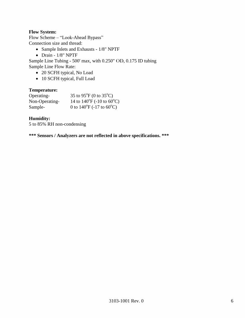
Flow System:
Flow Scheme – “Look-Ahead Bypass”
Connection size and thread:
Sample Inlets and Exhausts - 1/8" NPTF
Drain - 1/8" NPTF
Sample Line Tubing - 500' max, with 0.250" OD, 0.175 ID tubing
Sample Line Flow Rate:
20 SCFH typical, No Load
10 SCFH typical, Full Load
Temperature:
Operating- 35 to 95oF (0 to 35
oC)
Non-Operating- 14 to 140oF (-10 to 60
oC)
Sample- 0 to 140oF (-17 to 60
oC)
Humidity:
5 to 85% RH non-condensing
*** Sensors / Analyzers are not reflected in above specifications. ***
7
3103-1001 Rev. 0
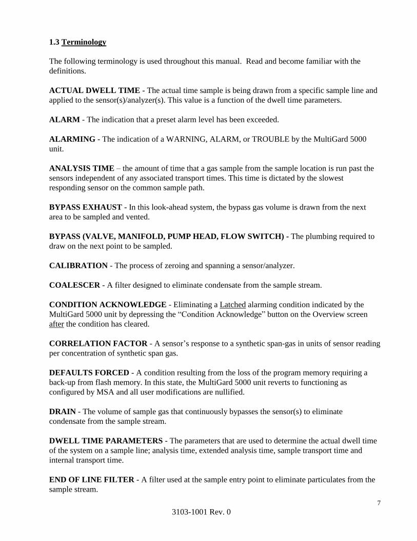
1.3 Terminology
The following terminology is used throughout this manual. Read and become familiar with the
definitions.
ACTUAL DWELL TIME - The actual time sample is being drawn from a specific sample line and
applied to the sensor(s)/analyzer(s). This value is a function of the dwell time parameters.
ALARM - The indication that a preset alarm level has been exceeded.
ALARMING - The indication of a WARNING, ALARM, or TROUBLE by the MultiGard 5000
unit.
ANALYSIS TIME – the amount of time that a gas sample from the sample location is run past the
sensors independent of any associated transport times. This time is dictated by the slowest
responding sensor on the common sample path.
BYPASS EXHAUST - In this look-ahead system, the bypass gas volume is drawn from the next
area to be sampled and vented.
BYPASS (VALVE, MANIFOLD, PUMP HEAD, FLOW SWITCH) - The plumbing required to
draw on the next point to be sampled.
CALIBRATION - The process of zeroing and spanning a sensor/analyzer.
COALESCER - A filter designed to eliminate condensate from the sample stream.
CONDITION ACKNOWLEDGE - Eliminating a Latched alarming condition indicated by the
MultiGard 5000 unit by depressing the “Condition Acknowledge” button on the Overview screen
after the condition has cleared.
CORRELATION FACTOR - A sensor’s response to a synthetic span-gas in units of sensor reading
per concentration of synthetic span gas.
DEFAULTS FORCED - A condition resulting from the loss of the program memory requiring a
back-up from flash memory. In this state, the MultiGard 5000 unit reverts to functioning as
configured by MSA and all user modifications are nullified.
DRAIN - The volume of sample gas that continuously bypasses the sensor(s) to eliminate
condensate from the sample stream.
DWELL TIME PARAMETERS - The parameters that are used to determine the actual dwell time
of the system on a sample line; analysis time, extended analysis time, sample transport time and
internal transport time.
END OF LINE FILTER - A filter used at the sample entry point to eliminate particulates from the
sample stream.
8
3103-1001 Rev. 0
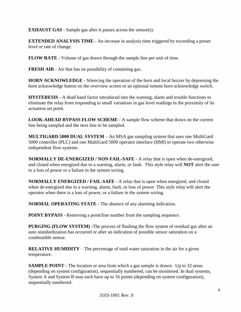
EXHAUST GAS - Sample gas after it passes across the sensor(s).
EXTENDED ANALYSIS TIME - An increase in analysis time triggered by exceeding a preset
level or rate of change.
FLOW RATE - Volume of gas drawn through the sample line per unit of time.
FRESH AIR - Air that has no possibility of containing gas.
HORN ACKNOWLEDGE - Silencing the operation of the horn and local buzzer by depressing the
horn acknowledge button on the overview screen or an optional remote horn acknowledge switch.
HYSTERESIS - A dead band factor introduced into the warning, alarm and trouble functions to
eliminate the relay from responding to small variations in gas level readings in the proximity of its
actuation set point.
LOOK-AHEAD BYPASS FLOW SCHEME - A sample flow scheme that draws on the current
line being sampled and the next line to be sampled.
MULTIGARD 5000 DUAL SYSTEM – An MSA gas sampling system that uses one MultiGard
5000 controller (PLC) and one MultiGard 5000 operator interface (HMI) to operate two otherwise
independent flow systems.
NORMALLY DE-ENERGIZED / NON FAIL-SAFE - A relay that is open when de-energized,
and closed when energized due to a warning, alarm, or fault. This style relay will NOT alert the user
to a loss of power or a failure in the system wiring.
NORMALLY ENERGIZED / FAIL-SAFE - A relay that is open when energized, and closed
when de-energized due to a warning, alarm, fault, or loss of power. This style relay will alert the
operator when there is a loss of power, or a failure in the system wiring.
NORMAL OPERATING STATE - The absence of any alarming indication.
POINT BYPASS - Removing a point/line number from the sampling sequence.
PURGING (FLOW SYSTEM) -The process of flushing the flow system of residual gas after an
auto standardization has occurred or after an indication of possible sensor saturation on a
combustible sensor.
RELATIVE HUMIDITY – The percentage of total water saturation in the air for a given
temperature.
SAMPLE POINT - The location or area from which a gas sample is drawn. Up to 32 areas
(depending on system configuration), sequentially numbered, can be monitored. In dual systems,
System A and System B may each have up to 16 points (depending on system configuration),
sequentially numbered.

9
3103-1001 Rev. 0
SAMPLE TRANSPORT TIME - The duration of time required to deliver a fresh sample from the
sample entry point to the MultiGard 5000 unit.
SENSOR/ANALYZER - A device that generates an electrical signal proportional to the
concentration of the specific gas it was calibrated to detect.
SPAN - Full-scale or up-scale reading on the meter display.
SPAN DRIFT - The deviation of sensor output from actual gas concentration applied.
SPAN GAS VALUE - The gas concentration that gives the instrument a full-scale or up-scale value.
This value is printed on the cylinder containing the calibration gas.
SPANNING - The process of applying span gas to a sensor/analyzer and placing a full-scale or span
gas indication on the unit during calibration.
STANDARDIZATION - The process of compensating for zero-drift and/or span-drift without re-
calibrating the sensor.
STANDARDIZATION HIGH TOLERANCE - The amount of correction to sensor output (in
sensor engineering units) that will result in a trouble condition indication by the MultiGard 5000 unit
and a disabling of the alarm functions.
STANDARDIZATION LOW TOLERANCE - The amount of correction to sensor output (in
sensor engineering units) that will result in a trouble condition indication by the MultiGard 5000 unit
while continuing to operate.
SYNTHETIC SPAN GAS - A gas that causes an up-scale reading used in place of the original span
gas for which the sensor/analyzer was calibrated.
TROUBLE - The indication that a fault condition has occurred.
USER CONFIGURED OUTPUT (UCO) - An output in the form of a solid state output or form C
relay contacts whose functionality may be defined by the end user.
WARNING - The indication that a preset warning level has been exceeded.
ZERO - A zero (0) indication on the meter display usually indicates fresh air (no gas present).
ZERO DRIFT - The deviation of sensor output when zero gas is applied.
ZEROING - The process of applying zero gas to a sensor/analyzer and placing a zero gas indication
on the unit during calibration.

10
3103-1001 Rev. 0
2. Installation
2.1 Receiving
Upon receipt of the unit, inspect the shipping cartons for signs of visible damage. Report any damage
to the carrier and note it on the receipt. The unit must be stored in a dry, secure place prior to its
installation and use. Store the unit in its original shipping carton.
2.2 Unpacking
To unpack the equipment, carefully remove the unit from its shipping container(s) in order to prevent
damage to sensitive electrical components. DO NOT use the coalescing filter assembly to lift the
unit as damage may occur. If any damage is found, report it to the shipper immediately. Search
through all packing material and containers to avoid inadvertently discarding usable or valuable
items. Report any item shortages immediately to MSA.
Using a screwdriver, open the door by turning 1/4 turn latches on the front of the door counter
clockwise (see Installation Drawing). Remove any packing material that may be found inside the
unit. Carefully inspect components and assemblies inside the unit. If damage or item shortage is
evident, advise the carrier. Remove the coalescing filter plug
2.3 Instrument Location Guidelines
The instrument’s performance is dependent on its location. Follow the guidelines below when
mounting the unit.
1. Acquire the appropriate hardware and locate the unit where personnel will see the display before
they enter the area being monitored.
2. Always mount the unit vertically with the display at eye level.
3. Do not mount the unit to structures subject to vibration and/or shock.
4. Do not locate the unit near an excessive heat source or in wet or damp locations.
5. Do not mount the unit in direct sunlight.
6. For proper cooling, allow at least six inches of clearance around all surfaces of the unit. Insure
that the cooling intakes on the base of the unit are free from obstructions that could block the flow of
air. The cooling exhaust hood on the top of the unit should be unobstructed and positioned off the
mounting surface as far as feasible for the installation.
7. Allow for unimpeded operation of the front door (see Installation Drawing) to allow access for
service and calibration.
11
3103-1001 Rev. 0
2.4 Wiring
All wiring to the MultiGard 5000 unit should be made via the plate at the bottom of the unit. Wire
120 VAC, 60 Hz single phase power to the MultiGard 5000 input terminals (see Field Wiring
Diagram) using a minimum of #16 AWG wire. A separate dedicated power source is recommended
to ensure that the unit remains powered when other circuits are shut down for servicing or routine
maintenance. The power source should be a “ground neutral” system. When a step down transformer
is used, an ungrounded or floating system can result. If an isolation transformer is used, the neutral
side of the secondary transformer should be grounded. Always conform to NEMA and NEC
standards pertaining to installations of this type.
Refer to the wiring diagram showing interconnecting wire between the unit and any other devices.
Relay wiring should be separate from power wiring. Each relay has contacts for normally open,
normally closed and common terminals. Wire to the trouble relays normally closed contact (contact
closed due to loss of power) to provide for fail-safe relay activation on loss of power.
WARNING
Wire Trouble Relay to operate an externally powered device (horn,
beacon, computer, PLC, etc.) using the common and normally closed
contacts for fail-safe operation on loss of power. The Trouble Relay
is an important safety device and failure to wire as specified will
result in no indication should gas detection system malfunction
and/or become disabled.
The horn and local buzzer can be silenced by pressing the HORN ACKNOWLEDGE button on the
Overview screen or through an optional remote horn acknowledge switch (see Field Wiring
Diagram).
CAUTION
Do not connect any system controlled process shut down circuits
until the system has been function checked, calibrated and is ready
for normal operation. False alarms may occur if this connection is
done before full system startup is completed.
12
3103-1001 Rev. 0
2.5 Plumbing
NOTE: This section specifically applies to the standard MultiGard 5000 system look-ahead bypass
flow scheme. Refer to Section 1 if your system employs a custom flow scheme.
Remove all shipping plugs from sample point inlets, exhausts and drain.
Sample point supply lines should be 0.250" OD, 0.175" ID, with a maximum sample line length of
500 ft. As a general rule, sample lines should be kept as short as possible to reduce sample transport
time.
Sample point tube entries should be placed in areas that provide the unit with the best representative
gas sample to be detected. In large areas where multiple sample point entries are located, air flow
patterns must be taken into considered. Ventilation smoke tubes (P.N. 458480) are useful in
determining air flow patterns in ambient sampling areas.
The samples must be adequately filtered and free of any liquid contamination before entering the
system. End of line particulate filters must be installed at all sample point tube entries (see Flow
Diagram). The sample point tube entries must be unobstructed to allow the gas sample to flow freely
to the system. Use only materials that are compatible with the gases in the sample flow system to
ensure an accurate gas sample is delivered to the system. Ensure that all tubing bends are wide
enough to prevent kinking or restriction in sample flow.
When connecting fittings to the sample point inlets, exhaust, and/or drain ports, be sure to not over-
tighten the fittings. Overtightening the fittings may cause damage to the sample point manifold.
Exhaust and drain gas flow should be properly vented to a safe area. When exhausting outdoors,
make sure that rain or water sources cannot enter the exhaust lines. Do not combine any
sensor/analyzer exhausts or drain lines. Increase exhaust line diameter by a minimum of 1/8" per 20
ft. of exhaust line. Do not back pressure the exhaust lines by restricting flow. Exhaust lines should
also be checked for obstructions. Also, do not connect exhaust lines to a vacuum source.
2.5.1 Sample Line Leak Checking
WARNING
Leak-check all sample lines at start up and regularly thereafter.
Leaking sample lines will cause sample dilution and lead to
erroneous lower than actual readings. Failure to leak-check the
sample lines may result in a hazardous condition.
13
3103-1001 Rev. 0
3. System Start-up / Set-up
3.1 Power-Up Sequence
Remove pump tie down. Activate the pump circuit breaker and then activate the system circuit
breaker. Refer to Figure 3.1 for location of components referred to in this section.
Observe the following sequence:
1. Power indicator on controller power supply turns on.
2. Pump turns on.
3. Display turns on.
4. Processor “OK” LED will remain red for a few seconds. The controller will perform a series of
internal checks. During this time the controller LED’s will flash on and off. Once the system checks
have been completed, the “OK”, “I/O”, “LINK 1” and “RUN” LED’s will become green. “LINK 2”
will flash steadily green.
5. Approximately 45 seconds into start-up, the unit will begin to sequence and flow should be
observed on the flow meter.
3.2 Flow Adjustment
Use the system control screen to place the unit in manual mode (see section 4.1.6). Step the system
to the line with longest length of tubing or least amount of flow as observed on the flowmeter.
Adjust the flow meter valve for nominal sensor/analyzer flow (refer to Section 1 for the appropriate
value for your specific system). This flow rate is dependent on the sensor(s) installed in the unit.
Reset the unit to auto-sequencing mode.
All calibration gases should be equipped with a dual stage pressure regulator. Connect the gas to
the appropriate calibration port. Refer to Section 1 for the type of gas and port assignment for your
specific system. Use the Manual Calibration display screen (see section 4.1.5) to activate the
calibration port being adjusted. Adjust the pressure regulator to obtain the required flow as viewed
on the flowmeter (approximately 2 PSI). DO NOT adjust the valve on the flowmeter at this point.
Repeat this procedure for the other calibration gases used by the system.

14
3103-1001 Rev. 0
3.2.1 Flow Switch
The MultiGard 5000 System is equipped with a sample flow switch to ensure that sufficient sample
and calibration gas is applied to the sensor. The function of the bypass flow switch is to ensure that
the sample line flow rate exceeds the minimum requirements. The sample flow switch and the
bypass flow switch have been factory preset to close at the appropriate flow levels.
NOTE: If a flow switch is subjected to excessive flow rates, it may lead to a situation where the flow
switch does not respond by opening on loss of flow. Furthermore, a flow switch that is stuck closed
will prevent the unit from properly performing an internal flow diagnostic test that will result in an
incorrect “Manifold Leaks” error message. This may be corrected by tapping on the flow switch
until the desired effect is observed. If this does not correct the problem or the problem reoccurs, this
may be an indication of particle or residue accumulation in the flow switch. Under those
circumstances, the flow switch should be cleaned in accordance with the manufacturer’s data sheet
in Section 4. To clear a “Manifold Leaks” error message after a flow switch problem has been
detected and corrected, a leak test must be initiated and lead to a successful resolution. A diagnostic
leak test may be activated manually from the Diagnostics screen (see section 4.2.9).
3.3 Sample Transport Time
NOTE: Sections 3.3, 3.4 and 3.5 specifically apply to the standard MultiGard 5000 look-ahead
bypass flow scheme. Refer to Section 1 if your system employs a custom flow scheme.
To ensure that the slowest responding sensor is exposed to the gas sample for the entire analysis
time, the time it takes for the gas sample to be transported to the Multigard must be considered. To
allow for this variance in line length, a sample transport time parameter is entered when calculating
dwell time to ensure that a fresh sample is applied to the sensor(s). The sample transport time is a
function of the tubing inner diameter, length of tubing and the minimum sample line flow rate. The
standard recommended tubing is 0.250" OD, 0.175" ID nylon tubing (MSA part number 029207).
The Flow Diagram will indicate the part number for the recommended tubing for your system. Use
Table 3.1 or the equation provided below to enter the appropriate sample transport time to the
corresponding line number in the Extended Setup and Sample Transport Time screen (see section
4.2.6) .
15
3103-1001 Rev. 0
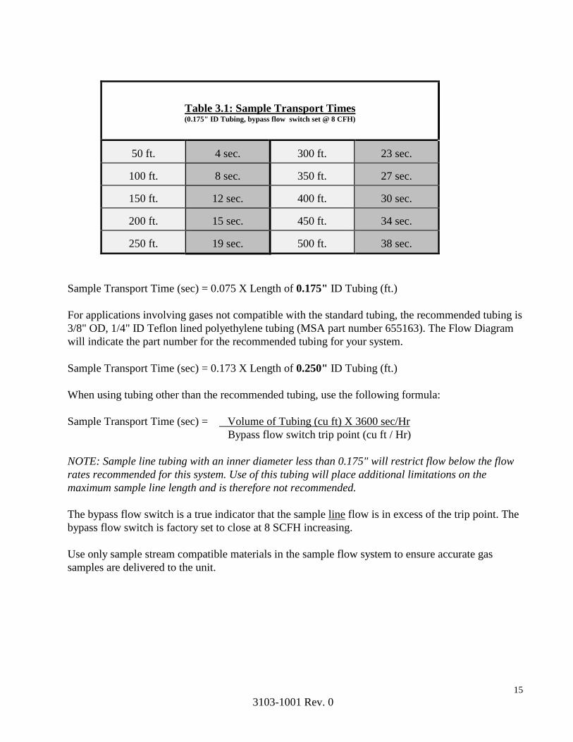
Table 3.1: Sample Transport Times (0.175" ID Tubing, bypass flow switch set @ 8 CFH)
50 ft.
4 sec.
300 ft.
23 sec.
100 ft.
8 sec.
350 ft.
27 sec.
150 ft.
12 sec.
400 ft.
30 sec.
200 ft.
15 sec.
450 ft.
34 sec.
250 ft.
19 sec.
500 ft.
38 sec.
Sample Transport Time (sec) = 0.075 X Length of 0.175" ID Tubing (ft.)
For applications involving gases not compatible with the standard tubing, the recommended tubing is
3/8" OD, 1/4" ID Teflon lined polyethylene tubing (MSA part number 655163). The Flow Diagram
will indicate the part number for the recommended tubing for your system.
Sample Transport Time (sec) = 0.173 X Length of 0.250" ID Tubing (ft.)
When using tubing other than the recommended tubing, use the following formula:
Sample Transport Time (sec) = Volume of Tubing (cu ft) X 3600 sec/Hr
Bypass flow switch trip point (cu ft / Hr)
NOTE: Sample line tubing with an inner diameter less than 0.175" will restrict flow below the flow
rates recommended for this system. Use of this tubing will place additional limitations on the
maximum sample line length and is therefore not recommended.
The bypass flow switch is a true indicator that the sample line flow is in excess of the trip point. The
bypass flow switch is factory set to close at 8 SCFH increasing.
Use only sample stream compatible materials in the sample flow system to ensure accurate gas
samples are delivered to the unit.

16
3103-1001 Rev. 0
3.4 Dwell Time Parameters
NOTE: Sections 3.3, 3.4 and 3.5 specifically apply to the standard MultiGard 5000 look-ahead
bypass flow scheme. Refer to Section 1 if your system employs a custom flow scheme.
WARNING
Entering correct Dwell Time Parameters is critical to proper system
operation. Incorrect entries may lead to a hazardous situation.
Contact MSA if you have any questions related to the MultiGard
5000 Gas Sampling System Dwell Time Parameters.
The components make up the dwell time of the MultiGard 5000 unit on a sample point are referred
to as the dwell time parameters. These parameters are the sample transport time for the specific
point, the system internal transport time, the sample analysis time, and extended analysis time. The
sample analysis time and extended analysis time are entered in the Extended Setup/Sample Transport
Time screen (see section 4.2.6). These two factors are to be set in conjunction with the extended
analysis time trigger.
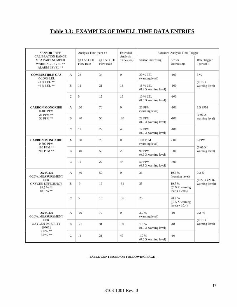
Table 3.3 is provided to assist in determining the appropriate dwell parameters. For each sensor
indicated, three options are provided; A, B and C. Selecting option A will require a longer cycle time
for the system but provide the least wear on the sample and bypass solenoid valves. Selecting option
C will allow for a shorter cycle time for the system leading to a quicker response to a leak at the
expense of decreasing the life span of the sample and bypass solenoid valves. Option B represents a
compromise between options A and C. Select the option which best suits your gas detection
requirements.
Examine the same row for each sensor to determine the slowest responding sensor in the MultiGard
5000 Gas Sampling System. Select one of option A, B or C for that sensor. Enter the analysis time,
extended analysis time and triggers for extended analysis time associated with the option selected.
For analysis time, use the column with the sample flow rate recommended for your specific system.
The analysis time and extended analysis time are common to all sensors. The triggers for extended
analysis time are independent for each sensor.
For the other sensors, select the option that has the longest analysis time that is less than the analysis
time for the slowest responding sensor previously determined. Enter the extended analysis triggers
for that sensor indicated by that option. Repeat this process for all the other sensors that may be
installed.
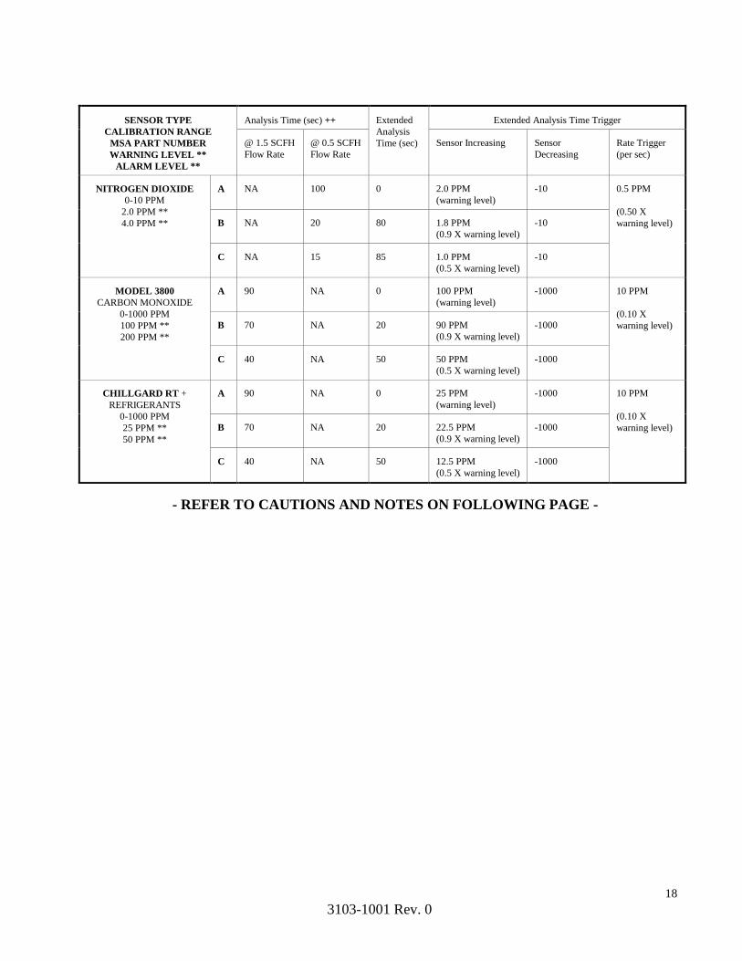
Refer to Section 1 and/or Section 3 for dwell time for any sensor/analyzer not indicated in Table 3.3.
17
3103-1001 Rev. 0
Table 3.3: EXAMPLES OF DWELL TIME DATA ENTRIES
SENSOR TYPE
CALIBRATION RANGE
MSA PART NUMBER
WARNING LEVEL **
ALARM LEVEL **
Analysis Time (sec) ++
Extended
Analysis
Time (sec)
Extended Analysis Time Trigger
@ 1.5 SCFH
Flow Rate
@ 0.5 SCFH
Flow Rate
Sensor Increasing
Sensor
Decreasing
Rate Trigger
( per sec)
COMBUSTIBLE GAS
0-100% LEL
20 % LEL **
40 % LEL **
A
24
34
0
20 % LEL
(warning level)
-100
3 %
(0.16 X
warning level) B
11
21
13
18 % LEL
(0.9 X warning level)
-100
C
5
15
19
10 % LEL
(0.5 X warning level)
-100
CARBON MONOXIDE
0-100 PPM
25 PPM **
50 PPM **
A
60
70
0
25 PPM
(warning level)
-100
1.5 PPM
(0.06 X
warning level) B
40
50
20
22 PPM
(0.9 X warning level)
-100
C
12
22
48
12 PPM
(0.5 X warning level)
-100
CARBON MONOXIDE
0-500 PPM
100 PPM **
200 PPM **
A
60
70
0
100 PPM
(warning level)
-500
6 PPM
(0.06 X
warning level) B
40
50
20
90 PPM
(0.9 X warning level)
-500
C
12
22
48
50 PPM
(0.5 X warning level)
-500
OXYGEN
0-25%, MEASUREMENT
FOR
OXYGEN DEFICIENCY
19.5 % **
18.0 % **
A
40
50
0
25
19.5 %
(warning level)
0.3 %
(0.22 X (20.8-
warning level)) B
9
19
31
25
19.7 %
((0.9 X warning
level) + 2.08)
C
5
15
35
25
20.2 %
((0.5 X warning
level) + 10.4)
OXYGEN
0-10%, MEASUREMENT
FOR
OXYGEN IMPURITY
807071
2.0 % **
5.0 % **
A
60
70
0
2.0 %
(warning level)
-10
0.2 %
(0.10 X
warning level) B
21
31
39
1.8 %
(0.9 X warning level)
-10
C
11
21
49
1.0 %
(0.5 X warning level)
-10
- TABLE CONTINUED ON FOLLOWING PAGE -
18
3103-1001 Rev. 0
SENSOR TYPE
CALIBRATION RANGE
MSA PART NUMBER
WARNING LEVEL **
ALARM LEVEL **
Analysis Time (sec) ++
Extended
Analysis
Time (sec)
Extended Analysis Time Trigger
@ 1.5 SCFH
Flow Rate
@ 0.5 SCFH
Flow Rate
Sensor Increasing
Sensor
Decreasing
Rate Trigger
(per sec)
NITROGEN DIOXIDE
0-10 PPM
2.0 PPM **
4.0 PPM **
A
NA
100
0
2.0 PPM
(warning level)
-10
0.5 PPM
(0.50 X
warning level) B
NA
20
80
1.8 PPM
(0.9 X warning level)
-10
C
NA
15
85
1.0 PPM
(0.5 X warning level)
-10
MODEL 3800
CARBON MONOXIDE
0-1000 PPM
100 PPM **
200 PPM **
A
90
NA
0
100 PPM
(warning level)
-1000
10 PPM
(0.10 X
warning level) B
70
NA
20
90 PPM
(0.9 X warning level)
-1000
C
40
NA
50
50 PPM
(0.5 X warning level)
-1000
CHILLGARD RT +
REFRIGERANTS
0-1000 PPM
25 PPM **
50 PPM **
A
90
NA
0
25 PPM
(warning level)
-1000
10 PPM
(0.10 X
warning level) B
70
NA
20
22.5 PPM
(0.9 X warning level)
-1000
C
40
NA
50
12.5 PPM
(0.5 X warning level)
-1000
- REFER TO CAUTIONS AND NOTES ON FOLLOWING PAGE -

19
3103-1001 Rev. 0
WARNING
Typical WARNING and ALARM set-points shown in Table 3.3 are
for reference only. The user of this gas sampling system must
determine what concentration of a specific gas poses a hazard to the
specific site where this equipment is installed and the concentrations
where a warning and alarm indication is required. Failure to set
appropriate warning and alarm set-points can result in serious
personal injury or death.
+ Typical data for units calibrated for the detection of HCFC-123. Other refrigerants may
require less stringent set points.
++ Analysis time is a function of the sample flow rate. Refer to the Custom System
Definition Data Sheet in Section 1 for the recommended flow rate for your system.
Notes:
Table data entries are based on warning levels selected.
Table data entries are based on readings for 98% sensor accuracy.
A sensor increasing or rate trigger set at sensor full scale effectively disables that trigger.
A sensor decreasing trigger set at minus sensor full scale effectively disables that trigger.
20
3103-1001 Rev. 0
3.5 Actual Dwell Time
NOTE: Sections 3.3, 3.4 and 3.5 specifically apply to the standard MultiGard 5000 look-ahead
bypass flow scheme. Refer to Section 1 if your system employs a custom flow scheme.
The purpose of the look ahead bypass is to draw on the next sequential sample line to reduce or in
some cases even eliminate the sample transport time. The processor continuously uses the dwell time
parameters and the actual programmed sampling sequence to determine the actual dwell time. For
every line, the actual dwell time is calculated according to the following formula:
Actual Dwell Time (line n) = Sample Transport Time (line n) - Dwell Time of Previous Position in
Programed Sequence + Internal Transport Time + Analysis Time + Extended Analysis Time
NOTE: The previous position should be verified in the actual programed sampling sequence.
With precautions taken such that the minimum actual dwell time is never less than the sum of the
analysis time, extended analysis time and internal transport time.
The internal transport time is a factory configured constant that is determined to be the time required
to transport the sample from the sample manifold to the sensor(s). The internal transport time for this
system is 10 seconds.
The extended analysis time is only a factor if triggered by a preset rate or level condition.
The actual dwell time of the current sample point is displayed on the Sequencer Control display
screen (see section 4.1.6).

21
3103-1001 Rev. 0
3.6 Auto Standardize Mode
When Auto Standardize is enabled, initial start-up of a MultiGard 5000 System will not proceed
correctly without calibration gases available. The “Auto Standardization Not Performed” flag will
remain on the MultiGard 5000 Display. MultiGard 5000 System monitoring will proceed with
uncorrected analyzer values.
The absence of calibration gases will also result in Zero, Span 1 or 2 “Flow Failure” trouble
indications from the MultiGard 5000 System when Auto Standardize is attempted. This indicator is
visible on the Manual Calibration screen.
The analog signals from the sensors are scaled and corrected for any possible drift during the
MultiGard 5000 Auto Standardize Mode. Failure to have calibration gas available to the MultiGard
5000 System during the Auto Standardize Mode will abort the scaling and correction process. Prior
values will be used until a full Auto Standardize cycle can be completed.
CAUTION
When MultiGard 5000 Auto Standardize Mode is enabled
calibration gases must be available at all times.
If a calibration gas source is not available during Auto-Standardize
Mode MultiGard 5000 monitoring may be adversely affected.

22
3103-1001 Rev. 0
4. Operator Interface
The operator interface for the MultiGard 5000 unit is a 10.4”color touch-screen that provides both
information display and user input. This section applies to all unit configurations as well as
illustrating the single system versus dual system screen differences.
Throughout this chapter the screens for the MultiGard 5000 24/32 point unit are shown in the
figures. Users of MultiGard 5000 8/16 units should note the following rules on using the same
operator manual:
The location of any item is in the same relative position for all system styles.
The same information content is provided on each screen for all system styles.
Wherever 32 points of information are shown in the figures, 16 points of information will
actually be seen on the screens in a similar format.
The phrases underlined and in quotes which lead to a description of an item still refer to the
figures. Any changes will be noted in the description (see next bullet).
In the item descriptions point ranges or references to system size may be specified which match
the figure. Substitute the numbers in brackets ( [] ) in place of those in the sentence.
Any exceptions to these rules will be discussed in the appropriate section.
Below is one example showing the similarity between a MultiGard 5000 8/16 screen and a MultiGard
5000 24/32 screen using the rules described above where appropriate.
MultiGard 5000 Unit 8/16 MultiGard 5000 Unit 24/32
Figure 1: Overview Screen (8 or16 Point System) Figure 2: Overview Screen (24 or 32 Point System)

23
3103-1001 Rev. 0
Sample text related to the dual MultiGard units.
This information can be ignored by users of single MultiGard units.
Users of MultiGard 5000 Dual 8 and MultiGard 5000 Dual 16 units should note the following rules
on using the same operator manual:
The same information content is provided on each screen across all models. The location of
some items may be different between the single and dual models.
Wherever dual MultiGard 5000 data is presented based on the number of sample points the
quantity will vary between 8 or 16 and be presented in a similar manner.
The phrases underlined and in quotes which lead to a description of an item still refer to the
original figures. In addition these items in the dual MultiGard 5000 system are specifically
labeled System A (SYS A) and System B (SYS B) to distinguish between the two separate
systems. Items common to the overall assembly do not use this designation.
When explicit labeling is not used the header text System A: and System B: are used.
Everything directly under these headers then applies to the system as labeled.
The relative position of System A grouped data is on the left. The relative position of System
B grouped data is on the right. Data common to the overall assembly is located in the center
or where space permits.
Any special notes and exceptions to these rules will be discussed in the appropriate section and
will be visually distinguished by the text box style as shown below.

24
3103-1001 Rev. 0
Below is one example screen using the rules described above where appropriate.
MultiGard 5000 Dual 8/16
Figure 3: Overview (Dual 16 Point System)
All MultiGard 5000 touchscreen displays have a screen saver feature enabled. The screen will turn
off after 30 minutes of touch inactivity. After it turns off, the first touch will restore the screen to
normal operation.
The following sections describe the screen package of the MultiGard 5000 unit which and is divided
into an open access part for use by anyone and a secured access part for the responsible system
operator.
4.1 Operational Screens - OPEN ACCESS
The first of two parts which make up the screen package is open access. This part is intended to
provide everything an operator needs to know about the gases being monitored and the operation of
MultiGard 5000 unit.

25
3103-1001 Rev. 0
The following figure, MultiGard 5000 Screen Hierarchy, Part 1 of 2, summarizes this portion of the
package and can be used as a "road map" to system operation.
Figure 4: MultiGard Screen Hierarchy, part 1 of 2
26
3103-1001 Rev. 0
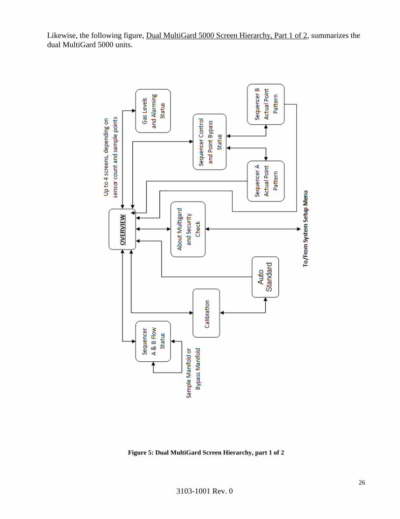
Likewise, the following figure, Dual MultiGard 5000 Screen Hierarchy, Part 1 of 2, summarizes the
dual MultiGard 5000 units.
Figure 5: Dual MultiGard Screen Hierarchy, part 1 of 2
27
3103-1001 Rev. 0
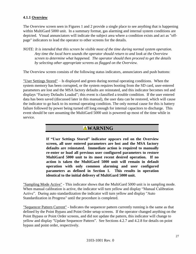
4.1.1 Overview
The Overview screen seen in Figures 1 and 2 provide a single place to see anything that is happening
within MultiGard 5000 unit. In a summary format, gas alarming and internal system conditions are
depicted. Visual annunciators will indicate the subject area where a condition exists and act as "off-
page" indicators to lead the operator to other screens for the details.
NOTE: It is intended that this screen be visible most of the time during normal system operation.
Any time the local horn sounds the operator should return to and look at the Overview
screen to determine what happened. The operator should then proceed to get the details
by selecting other appropriate screens as flagged on the Overview.
The Overview screen consists of the following status indicators, annunciators and push buttons:
"User Settings Stored" – Is displayed and green during normal operating conditions. When the
system memory has been corrupted, or the system requires booting from the SD card, user-entered
parameters are lost and the MSA factory defaults are reinstated, and this indicator becomes red and
displays “Factory Defaults Loaded”; this event is classified a trouble condition. If the user entered
data has been saved (discussed later in this manual), the user data can be restored, which will cause
the indicator to go back to its normal operating condition. The only normal cause for this is battery
failure followed by power being turned off long enough for internal capacitors to discharge. This
event should be rare assuming the MultiGard 5000 unit is powered up most of the time while in
service.
WARNING
If “User Settings Stored” indicator appears red on the Overview
screen, all user entered parameters are lost and the MSA factory
defaults are reinstated. Immediate action is required to manually
re-enter or load all previous user configured parameters to restore
MultiGard 5000 unit to its most recent desired operation. If no
action is taken the MultiGard 5000 unit will remain in default
operation with only common alarming and user configured
parameters as defined in Section 1. This results in operation
identical to the initial delivery of MultiGard 5000 unit.
"Sampling Mode Active" - This indicator shows that the MultiGard 5000 unit is in sampling mode.
When manual calibration is active, the indicator will turn yellow and display “Manual Calibration
Active”. During auto standardization the indicator will turn yellow and display "Auto
Standardization in Progress" until the procedure is completed.
"Sequencer Pattern Current" - Indicates the sequencer pattern currently running is the same as that
defined by the Point Bypass and Point Order setup screens. If the operator changed anything on the
Point Bypass or Point Order screens, and did not update the pattern, this indicator will change to
yellow and display "Update Sequencer Pattern”. See Sections 4.2.7 and 4.2.8 for details on point
bypass and point order, respectively.

28
3103-1001 Rev. 0
"No Leaks Detected" - This indicator is the result of the sample and bypass manifold leak test
performed by MultiGard 5000 unit upon power up and every 8 hours thereafter. This test can also
be manually triggered on the Diagnostics screen. If the system leaks this indicator will change to
red and display "Leaks Detected".
"Sensor Alarming Enabled" - This indicator follows the state of the manual sensor alarming disable
push button on the Diagnostics screen. When disabled, the indicator will turn red and display
"Sensor Alarming Disabled".
“Alarming Disabled A.S. Upper Range Out Of Tolerance” – This indicator will appear when an
auto standardization was completed and any sensor’s upper range is out of tolerance. All alarming
will be disabled. This indicator does not follow the manual sensor alarming disable push button on
the Diagnostics screen.
"PIR Ready" - This indicator shows the enable/disable and ready/not ready analyzer status in
combination as follows: When disabled the message "Analyzers Ready Disabled" is present
permanently. When enabled, the indicator will show "PIR Ready" or "PIR Warming Up or
Faulted". Note that the analyzers enable/disable is a MSA factory configured parameter that is
available only when the MSA analyzers in use provide a ready relay output.
"Auto Standardization Not Performed" – This indicator appears when an auto standardization has
never been performed when auto standardization has been factory enabled. The values used in the
correction of gas data are unknown and during this time uncorrected data is presented by the
MultiGard 5000 unit.
"Sample/Bypass Flow Status" & Annunciator - This push button changes the screen to view the
sample and bypass manifold flow status. The annunciator is an "off-page" indicator which is
normally invisible. It appears as two flashing red squares when any flow problem exists.
"Calibration” & Annunciator – This push button changes the screen to view and operate calibration
features. The annunciator is an "off-page" indicator which is normally invisible. It appears as two
flashing red rectangles when problems exist resulting from any auto standardization tolerance being
out, or loss of any calibration gas.
"Sequencer Control" - This push button changes the screen to view and operate the Sequencer
Control features of MultiGard 5000 unit.
"System Info" – This push button changes the screen to view information about the MultiGard 5000
unit and allows entry of a password to enter the system setup areas (part 2 of the screen package) of
the MultiGard 5000 unit.
"Sensor 1 Points 1-16 OK" through "Sensor 4 Points 17-32 OK" - A group of 8 push buttons which
changes the screen to view sensor data and alarming status. Whenever a condition exists that
requires an operators attention, the button will turn red and indicate "Sensor 1 Point 1-16 [1-8]"
through "Sensor 4 Points 17-32”.
"Horn Silence" - This is a push button which silences the horn. The frame of the button will flash
red during a trouble, warning or alarm condition. See the Chapter 5, Common Alarming for more
details.
29
3103-1001 Rev. 0
"Condition Acknowledge" – This is a push button which acknowledges the following conditions
when operating in latched mode, trouble, warning, or alarm. The frame of the button will flash red
when there is a condition that needs to be acknowledged. If not operating in a latched mode, this
button is not required for condition clearing. See Alarming, Chapter 5 for more details.
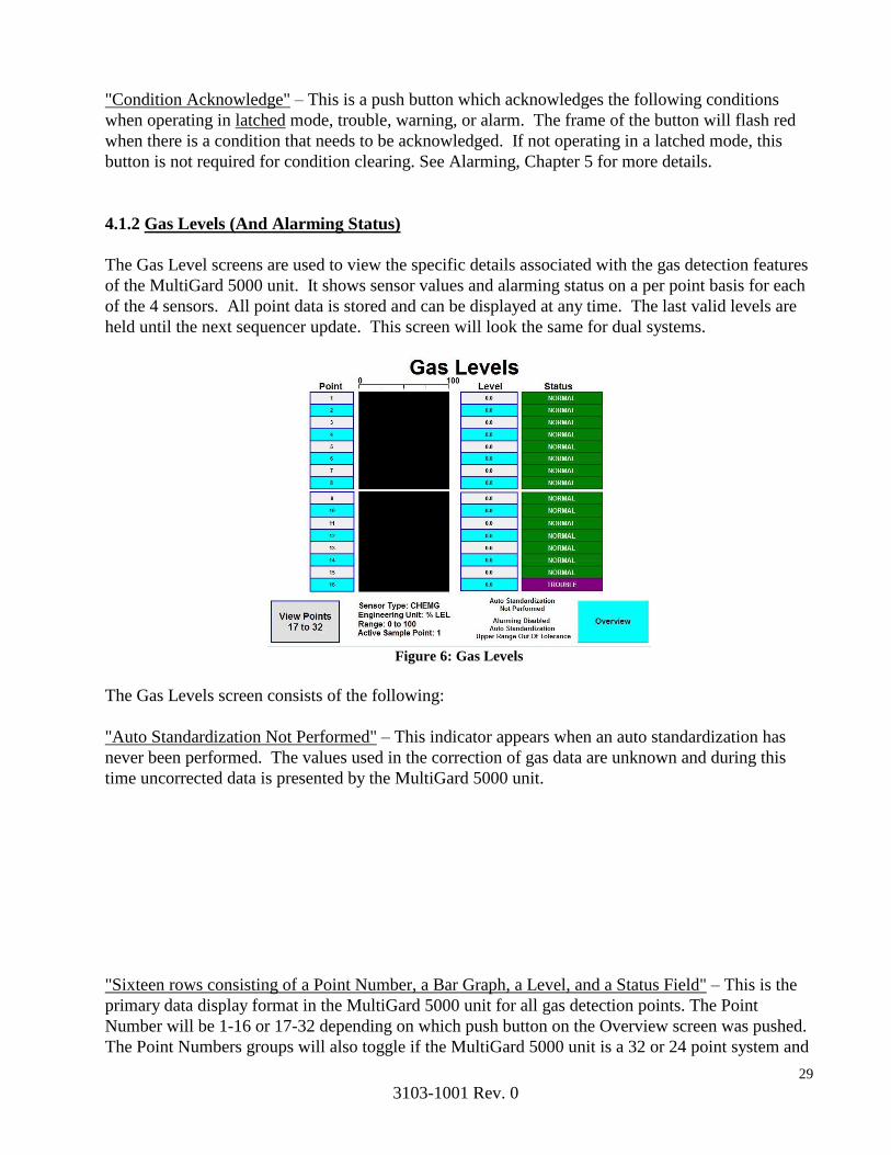
4.1.2 Gas Levels (And Alarming Status)
The Gas Level screens are used to view the specific details associated with the gas detection features
of the MultiGard 5000 unit. It shows sensor values and alarming status on a per point basis for each
of the 4 sensors. All point data is stored and can be displayed at any time. The last valid levels are
held until the next sequencer update. This screen will look the same for dual systems.
Figure 6: Gas Levels
The Gas Levels screen consists of the following:
"Auto Standardization Not Performed" – This indicator appears when an auto standardization has
never been performed. The values used in the correction of gas data are unknown and during this
time uncorrected data is presented by the MultiGard 5000 unit.
"Sixteen rows consisting of a Point Number, a Bar Graph, a Level, and a Status Field" – This is the
primary data display format in the MultiGard 5000 unit for all gas detection points. The Point
Number will be 1-16 or 17-32 depending on which push button on the Overview screen was pushed.
The Point Numbers groups will also toggle if the MultiGard 5000 unit is a 32 or 24 point system and

30
3103-1001 Rev. 0
the "View Points 17 to 32" button is pressed. The bar graphs are presented for a visual indication of
gas levels and are especially useful in applications where continuous gas levels are present. The
Level is the actual gas reading corrected by auto standardization data and displayed in engineering
units as indicated at the bottom of the screen. The Status indicators show the alarming states
associated with each point.
The Status indicators accurately depict the combined alarming state of each point consisting of
trouble, warning, and alarm level detection. All of the possible messages that can appear are as
follows: "Normal", "TROUBLE", "WARNING", "TRBL/WARN", "ALARM!", "TRBL/ALARM",
"ALARM!/WARN", and "TRBL/W/A". Note that some of these messages may never appear.
Which messages are valid is dependent on the sensor type, the MSA factory warning/alarm selection
of increasing or decreasing, and the user entered set point values.
When the sequencer is operated in the manual mode the data presentation and status indication
described above becomes live after the dwell time has expired for the selected sample point.
“Range:” – This is a text indicator telling the operator the range of sensor. This range should
associate with the scale that is above the bar graph.
"Engineering Units:" - This is the engineering units associated with the named sensor.
“Alarming Disabled Auto Standardization Upper Range Out Of Tolerance” - This indicator will
appear when an auto standardization was completed and any sensor’s upper range is out of
tolerance. All alarming will be disabled. This indicator does not follow the manual sensor alarming
disable push button on the Diagnostics screen.
WARNING
If “Alarming Disabled Auto Standardization Upper Range Out Of
Tolerance” indicator appears on the Overview screen, the alarming
is disabled. Immediate action is required to manually calibrate the
sensor which caused this condition to occur followed by another
auto standardization. See Section 4.1.5, Section 3, and Section 4.1.4
for details. If no action is taken all alarming will stay disabled with
the MultiGard 5000 unit only indicating a trouble condition.
"View Points 17 to 32” - This is an HMI navigation push button that switches to the next 16 points
associated with the same sensor. Once this button is pushed it will indicate "View Points 1 to 16".
This button is not used on MultiGard 5000 unit 8 or 16 point systems.
"Sensor Type:" - This is a text indicator which identifies the type of sensor configured and what data
is currently being viewed.
"Active Sample Point:" - Shows the point number that is currently being sampled. In other words,
the next point that will get its level and status updated.
"Overview" - This is a button which switches the screen back to the Overview.

31
3103-1001 Rev. 0
4.1.3 Flow Status (Sample and Bypass)
The Flow Status screen shows specifically where a flow problem exists on both the sample and
bypass manifolds.
Figure 7: Sample Manifold Flow Status Figure 8: Sample Manifold Flow Status (Dual)
The Flow Status screen consists of the following:
"Sample Manifold Flow Status" - This is the screen title and it indicates which flow status is
currently being displayed. The title may also appear as "Bypass Manifold Flow Status" and changes
alternately with the "GOTO BYPASS" button described below..
"Point 1 Flow Normal" through "Point 32 Flow Normal" – During normal operation the array of 32
indicators are green and display “Point [XX] Flow Normal” for whichever manifold is selected.
When flow failures exist the indicator(s) will turn red and display "Point [XX] Flow FAILURE"
depending on which point and which manifold is in flow fail. [XX] will display which point
number, 1-32 is normal or in failure.
NOTE: Bypassing a point (eliminating a point from the sampling sequence) that has a sample or
bypass flow loss indication, will lead to a situation where the trouble condition cannot be cleared.
The MultiGard 5000 unit must access the line in question to determine that the fault condition has
been corrected whereby the CONDITION ACKNOWLEDGEbutton may be used to return the unit to
the normal operating state.
"Flow Loss on Sample!" – This indicator will show when viewing the “Bypass Manifold Flow
Status” screen and a flow failure has occurred in the sample manifold. When the screen is switched
to view the “Sample Manifold Flow Status” screen, this indicator turns off.
"Flow Loss On Bypass!" - This indicator will show when viewing the “Sample Manifold Flow
Status” screen and a flow failure has occurred in the bypass manifold. When the screen is switched
to view the “Bypass Manifold Flow Status” screen, this indicator turns off.
"GOTO Bypass" - This is a push button that changes the screen from displaying sample status to
bypass status. After being pushed the button now indicates "GOTO SAMPLE". Note that the screen

32
3103-1001 Rev. 0
title alternates between “GOTO Bypass” and “GOTO Sample”, depending on screen being viewed.
"Overview" - This is an HMI navigation button which switches the screen back to the Overview.
“Active Sampling Point” – This indicator shows which point is currently being sampled by the
system.
4.1.4 Auto Standardization
The auto standardization screen shows the operator all of the items of interest related to this function
and allows the operator to manually trigger the procedure. This screen is only accessible if the Auto
Standard feature is enabled. See section 4.2.11 for information on enabling and disabling the Auto
Standard feature.
Figure 9: Auto Standardization (Single) Figure 10: Auto Standardization (Dual)
The auto standardization screen consists of the following:
"Currently in Sample Mode" - This is a multistate indicator which shows the progress of the auto
standardization procedure. It stays as shown until the procedure begins. The indicator steps through
the following messages in this order: "Zero Gas Being Applied", "Span 1 Gas Being Applied",
"Span 2 Gas Being Applied", "Purging With Gas Sample", and finally back to "Currently in Sample

33
3103-1001 Rev. 0
Mode". Note that one of the span steps may be missing if the installed sensors do not require a
second span gas supply. .Dual MultiGard 5000 Systems
The multistate indicator showing all the various stages of auto standardization exists for both System
A and System B. All other items directly below these indicators apply to the
specific System that is called out by the indicator. Remember that Sensors 1 and 2 are associated
with System A and Sensors 3 & 4 are associated with System B.
Four columns consisting of ”Disable/Span 1/Span 2” Indicator, “Measured Zero”, “Measured Span”,
“Actual Zero Gas Value”, Span Type Indicator, “Span Gas Value”, and a Tolerance Indicator - These
seven items are duplicated for each sensor and are defined as follows: The "S[1-4] Disabled"
indicator will show for each sensor when auto standardization has not been MSA factory enabled.
When auto standardization is enabled the indicator will show “S[1-4]:Span 1” or “S[1-4]:Span 2”
depending on the span gas is required for each sensor. The “Measured Zero” is the real reading
captured during the zero phase of auto standardization. The “Measure Span” is the real reading
captured during the span phase of auto standardization. The Actual Zero Gas is the gas cylinder
concentration and is displayed as a reference. The Span Type Indicator reads "Actual" or "Synthetic"
depending on which type of span gas is being use. The Span Gas Value is the gas cylinder
concentration and is displayed as a reference. When the “Measured Zero” and “Actual Zero Gas”
values are equal and the “Measured Span” and “Span Gas” values are equal the sensor is in perfect
alignment. The Span Gas value may be converted if a synthetic span gas is being used and was MSA
factory configured. The tolerance indicator shows the combined status of any of the auto
standardization tolerances and is either "Tolerances OK" or "Tolerances Out !”.
When auto standardization tolerances are out, a manual calibration of the sensors is required to bring
the sensors back into tolerance limits. See Section 3 for specific details.
"Manual Calibration" & Annunciator Bar - This is an HMI navigation button which switches to the
Manual Calibration screen. The annunciator bar is normally an invisible indicator that will appear
and flash when a gas cylinder flow failure(s) exist.
"Start ASTD Now" - This is a push button that will trigger the auto standardization procedure. The
operator must press and hold the button 3 seconds for the auto standardization to start. Watch the
multistate indicator at the top of the screen for when the procedure starts. This start requirement
serves to prevent accidental false starts. Once started, the auto standardization procedure cannot be
stopped.
"Timed ASTD Disabled" - This indicator shows that the Timed auto standardization feature has been
disabled by the user or was left default. This indicator shows "Next Timed ASTD In:" when timed
auto standardization is enabled.
"DAYS To ASTD" - The number of days until the next auto standardization is performed. This field
is zero if the timed auto standardization is disabled.
"HRS To ASTD" - The number of hours until the next auto standardization is performed. This field
is zero if the timed auto standardization is disabled.
"MIN To ASTD" - The number of minutes until the next auto standardization is performed. This
field is zero if the timed auto standardization is disabled.
34
3103-1001 Rev. 0
"Overview" - This is an HMI navigation button which switches the screen back to the Overview.
“Alarming Disabled, Auto Standardization Upper Range Out of Tolerance” – This indicator appears
when an auto standardization upper limit has been exceeded. The operator must perform a manual
calibration of the sensor to clear this condition.
“Auto Standardization Not Perfomed” – This indicator appears when an auto standardization has
never been performed when auto standardization has been factory enabled. The values used in the
correction of gas data are unknown and during this time uncorrected data is presented by the
MultiGard 5000 unit.
4.1.5 Manual Calibration
The Manual Calibration screen is intended for use by the operator during sensor maintenance. It
displays uncorrected sensor readings and gas cylinder flows. It also allows selection of calibration
gases and entry into calibration mode for the purpose of manual sensor calibration. No Auto
standardization occurs while on this screen.
NOTE: If auto standardization has been factory enabled, and after the manual calibration mode has
been entered. Upon leaving the Manual Calibration screen a full auto standardization is triggered
automatically.
NOTE: This screen may be viewed without the auto standardization being triggered upon leaving,
as long as the manual calibration mode was never started. If the “GO TO MAN. CAL. MODE”
button is pressed at any point, an auto standardization WILL be performed.

35
3103-1001 Rev. 0
Figure 11: Manual Calibration Figure 12: Manual Calibration (Dual)
The Manual Calibration screen consists of the following:
"Sensor 1 Gas Level" through "Sensor 4 Gas Level" - The four large gas level displays, show the
real-time sensor gas readings without any corrections. These values are raw sensor readings that
are continuously updated and will NOT match the sensor bar graphs when auto standardization is
enabled. The sensor bar graphs show the corrected sensor readings. If auto standardization is not
enabled, the gas level displays on the Manual Calibration screen WILL match the sensor bar graphs.
"Select Gas:" - This is a three position selector switch which allows the selection of Zero, Span 1,
and Span 2 gases for application to the sensors. The selection may be done at any time and the actual
application occurs only when the “GO TO MANUAL CALIBRATION MODE” button is pressed,
starting the manual calibration mode.
"CURRENTLY SAMPLING" - This indicator advises the operator that he may enter the manual
calibration mode. When auto standardization is in progress the indicator shows "ASTD IN
PROGRESS" and the manual calibration is locked out until auto standardization is over.
“MANUAL CAL INACTIVE” – This normally green indicator alerts the operator as to what
calibration mode the system is in. When a manual calibration is active, the indicator will turn yellow
and display “MANUAL CAL ACTIVE”.
"Manual Time-out (MIN):" - This indicator shows the time that remains for manual calibration
before the manual calibration time-out occurs. It is MSA factory set to 30 minutes and begins
counting down when the manual calibration mode is entered. Upon time-out completion, a full Auto
standardization will be executed on systems where auto standardization has been factory enabled.
Once the auto standardization is complete, the system resumes gas sampling. On systems where auto
standardization is not enabled, the unit resumes sampling.
"GO TO MANUAL CALIBRATION MODE" - This is the push button used to go to manual
calibration. When pushed the system starts the manual calibration mode and the button indicates
"RETURN TO SAMPLE MODE". Once done with manual calibration, pressing the “RETURN TO
SAMPLE MODE” button will end the manual calibration mode. The same auto standardization
rules apply as if the system were to time-out as discussed previously.

36
3103-1001 Rev. 0
"Reset Manual Time-out" - This push button resets the time-out timer back to 30 minutes. It is
intended for operator use when sensor maintenance is expected to take longer than 30 minutes.
NOTE: After the manual calibration mode is entered and 30 minutes has elapsed, the manual
calibration mode ends and a full auto standardization is triggered automatically if factory enabled.
If more than 30 minutes is needed to perform the sensor maintenance, press the “Reset Manual
Time-Out” button to reset the 30 minute timer.
"Auto Standardization" - This is an HMI navigation button which changes the screen to auto
standardization.
"Zero Cylinder Flow Detected" - This indicator shows that the gas cylinder flow was normal during
the last calibration. It switches to " Zero Cylinder Flow Not Detected " when the gas cylinder is
empty or any other zero gas flow failure condition exists.
"Span 1 Cylinder Flow Detected" - This indicator shows that the gas cylinder flow was normal
during the last calibration. It switches to " Span 1 Cylinder Flow Not Detected" when the gas
cylinder is empty or any other span 1 gas flow failure condition exists.
" Span 2 Cylinder Flow Detected " - This indicator shows that the gas cylinder flow was normal
during the last calibration. It switches to " Span 2 Cylinder Flow Not Detected " when the gas
cylinder is empty or any other span 2 gas flow failure condition exists.
"Overview" - This is an HMI navigation button which switches the screen back to the Overview
screen.
4.1.6 Sequencer Control (And Point Bypass Status)
The Sequencer Control screen allows the operator to control the sequencer and to see the point
bypass status currently in effect. This screen also allows the operator to get to the Actual Point
Pattern screen.
Figure 13: Sequencer Control Figure 14: Sequencer Control (Dual)

37
3103-1001 Rev. 0
"Point Bypass Status:" - This is an array of 32 [16] indicators which show the point bypass. Any
point in green is not bypassed. Any point in red is bypassed and not sampling. Using this color
code, the operator can quickly see which points, if any, are currently being bypassed. In the
MultiGard 5000 24 [8] point system sample points 25-32 [9-16] are permanently bypassed.
"Combustible Level Exceeded – Purging System Lines" - This indicator only appears when the
system determines that a purge is required on the indicated point. This feature is only applicable
when the purge operation has been factory configured for MSA's catalytic combustible sensor. This
indicator refers to the sample point number shown in the “Active Sample Point:” indicator. This
indicator stays visible for the duration of the purge.
"Extended Analysis Time on Active Point" - This indicator only appears when any of the extended
analysis triggers discussed in section 3.4, are active for any sensor on the current sample point. This
indicator also refers to the sample point number shown in the “Active Sample Point:” indicator.
"Stepping Mode: Automatic" - This is a push button that switches the sequencer between automatic
and manual modes. When button is pressed to enter manual mode, the button turns red and flashes "
Stepping Mode: Manual” and a 15 minute time-out timer starts. At the end of the time-out timer, the
system will automatically return to automatic mode.
"Active Sample Point:" - This indicator shows sample valve the sequencer is currently sampling. It
is active in both automatic and manual modes.
"Step to Next Point" - This is a push button that steps the sequencer when in the manual mode. It is
not operational in the automatic mode.
"Actual Dwell Time:" - This indicator shows the actual dwell time for the current point number. See
Section 3.5 for a complete description of the dwell time calculation. This indicator shows the time in
seconds.
"Actual Point Pattern" - This is an HMI navigation button which changes the screen to view the
Actual Point Pattern currently being executed by the sequencer. .Dual MultiGard 5000 Systems
There are two Actual Point Pattern touch-buttons on the dual MultiGard 5000s; System A and
System B.
"Overview" - This is an HMI navigation button which switches the screen back to the Overview.
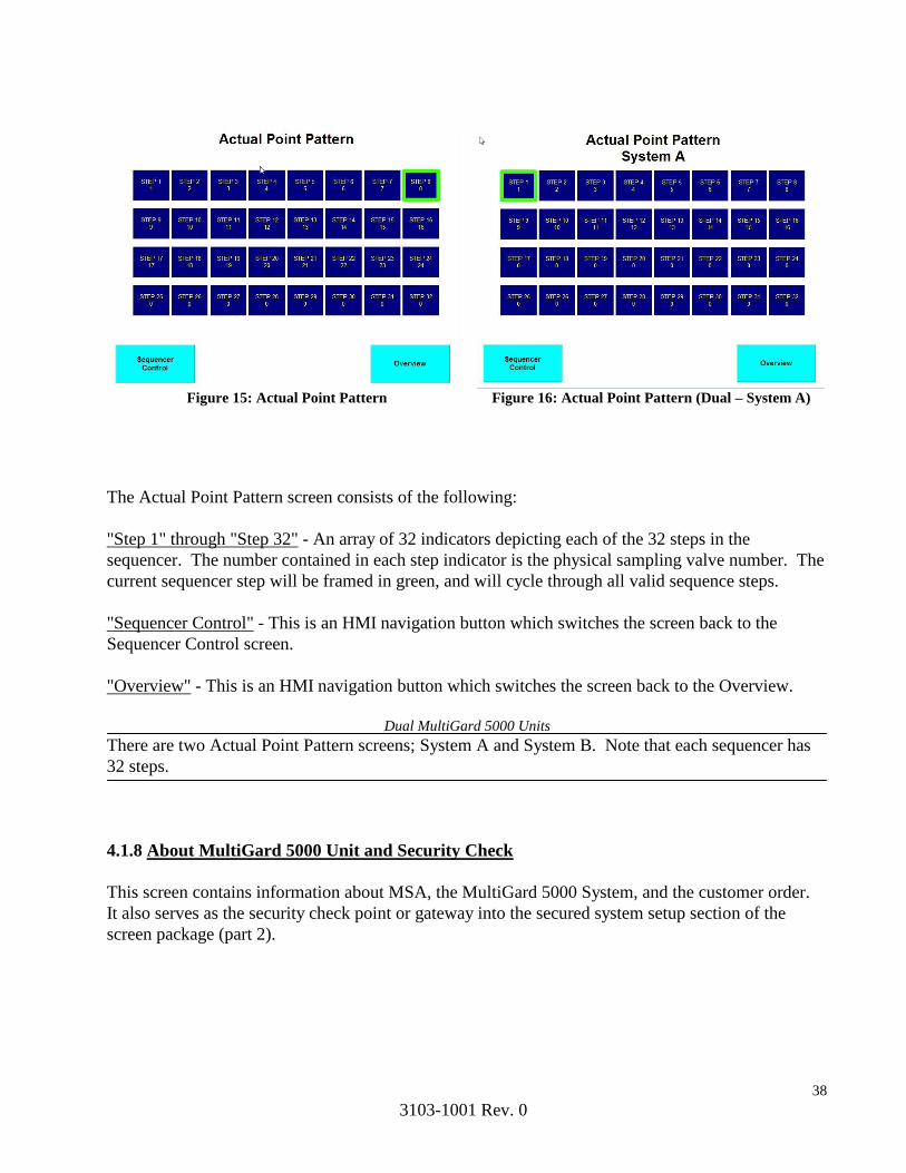
4.1.7 Actual Point Pattern
The Actual Point Pattern screen shows the current pattern (or order) in which the physical sample
valves are being opened by the sequencer. It is the combined result of the Point Order setup and
Point Bypass setup screens described in sections 4.2.8 and 4.2.7, respectively. Any sequencer step(s)
containing a point number zero in the Point Order setup screen is (are) eliminated in the Actual Point
Pattern. In addition, any point(s) bypassed on the Point Bypass setup screen is (are) also eliminated
in the Actual Point Pattern.
38
3103-1001 Rev. 0
Figure 15: Actual Point Pattern Figure 16: Actual Point Pattern (Dual – System A)
The Actual Point Pattern screen consists of the following:
"Step 1" through "Step 32" - An array of 32 indicators depicting each of the 32 steps in the
sequencer. The number contained in each step indicator is the physical sampling valve number. The
current sequencer step will be framed in green, and will cycle through all valid sequence steps.
"Sequencer Control" - This is an HMI navigation button which switches the screen back to the
Sequencer Control screen.
"Overview" - This is an HMI navigation button which switches the screen back to the Overview.
.Dual MultiGard 5000 Units
There are two Actual Point Pattern screens; System A and System B. Note that each sequencer has
32 steps.
4.1.8 About MultiGard 5000 Unit and Security Check
This screen contains information about MSA, the MultiGard 5000 System, and the customer order.
It also serves as the security check point or gateway into the secured system setup section of the
screen package (part 2).
39
3103-1001 Rev. 0
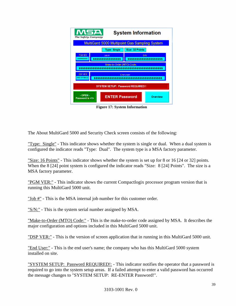
Figure 17: System Information
The About MultiGard 5000 and Security Check screen consists of the following:
"Type: Single" - This indicator shows whether the system is single or dual. When a dual system is
configured the indicator reads "Type: Dual". The system type is a MSA factory parameter.
"Size: 16 Points" - This indicator shows whether the system is set up for 8 or 16 [24 or 32] points.
When the 8 [24] point system is configured the indicator reads "Size: 8 [24] Points". The size is a
MSA factory parameter.
"PGM VER:" - This indicator shows the current Compactlogix processor program version that is
running this MultiGard 5000 unit.
"Job #" - This is the MSA internal job number for this customer order.
"S/N:" - This is the system serial number assigned by MSA.
"Make-to-Order (MTO) Code:" - This is the make-to-order code assigned by MSA. It describes the
major configuration and options included in this MultiGard 5000 unit.
"DSP VER:" - This is the version of screen application that in running in this MultiGard 5000 unit.
"End User:" - This is the end user's name; the company who has this MultiGard 5000 system
installed on site.
"SYSTEM SETUP: Password REQUIRED!: - This indicator notifies the operator that a password is
required to go into the system setup areas. If a failed attempt to enter a valid password has occurred
the message changes to "SYSTEM SETUP: RE-ENTER Password!".
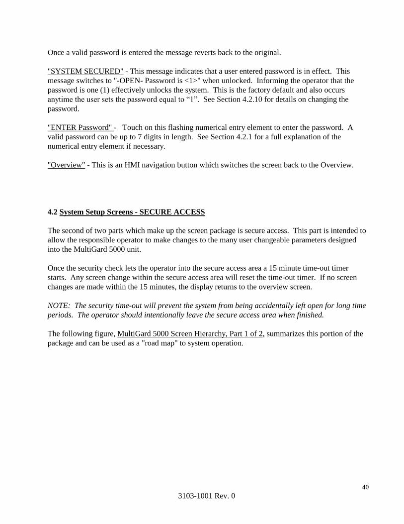
40
3103-1001 Rev. 0
Once a valid password is entered the message reverts back to the original.
"SYSTEM SECURED" - This message indicates that a user entered password is in effect. This
message switches to "-OPEN- Password is <1>" when unlocked. Informing the operator that the
password is one (1) effectively unlocks the system. This is the factory default and also occurs
anytime the user sets the password equal to “1”. See Section 4.2.10 for details on changing the
password.
"ENTER Password" - Touch on this flashing numerical entry element to enter the password. A
valid password can be up to 7 digits in length. See Section 4.2.1 for a full explanation of the
numerical entry element if necessary.
"Overview" - This is an HMI navigation button which switches the screen back to the Overview.
4.2 System Setup Screens - SECURE ACCESS
The second of two parts which make up the screen package is secure access. This part is intended to
allow the responsible operator to make changes to the many user changeable parameters designed
into the MultiGard 5000 unit.
Once the security check lets the operator into the secure access area a 15 minute time-out timer
starts. Any screen change within the secure access area will reset the time-out timer. If no screen
changes are made within the 15 minutes, the display returns to the overview screen.
NOTE: The security time-out will prevent the system from being accidentally left open for long time
periods. The operator should intentionally leave the secure access area when finished.
The following figure, MultiGard 5000 Screen Hierarchy, Part 1 of 2, summarizes this portion of the
package and can be used as a "road map" to system operation.

41
3103-1001 Rev. 0
Figure 18: Screen Hierarchy (1 of 2)
Likewise, the following figure, Dual MultiGard 5000 Screen Hierarchy, Part 2 of 2, summarizes the
Dual MultiGard 5000 units.
Figure 19: Screen Hierarchy (2 of 2)
Common Alarming Setup
System Setup Menu
Extended Setup & Transport Sample
Times
Setpoints (Trouble, Warning, & Alarm
Entries) Diagnostics
User Configured Outputs Option (#1 & #2 Setup)
Passwor
Change & Clock Sets
UCO Enables
___ 11 Screens
Steps 1-16 or or
Auto- Standardization
Setu
Sequencer Point Order
/ 4 screens
For Each Sensor
Sequencer Point Bypass
Common Alarming Setup
System Setup Menu
Setpoints (Trouble, Warning, & Alarm
Entries) Diagnostics
User Configured
Configured Outputs Option (#1 & #2 Setup)
UCO Enables Password Change & Clock Sets
___ 12
2 Screens
Auto- Standardization
Setup
p
Sequencer B Point Order
/ 4 screens
For Each Sensor
Sequencer A Point Order
Extended Setup & Transport
t Sample Times
Sequencers A & B
Point Bypass
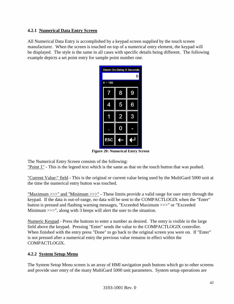
42
3103-1001 Rev. 0
4.2.1 Numerical Data Entry Screen
All Numerical Data Entry is accomplished by a keypad screen supplied by the touch screen
manufacturer. When the screen is touched on top of a numerical entry element, the keypad will
be displayed. The style is the same in all cases with specific details being different. The following
example depicts a set point entry for sample point number one.
Figure 20: Numerical Entry Screen
The Numerical Entry Screen consists of the following:
"Point 1" - This is the legend text which is the same as that on the touch button that was pushed.
"Current Value:" field - This is the original or current value being used by the MultiGard 5000 unit at
the time the numerical entry button was touched.
"Maximum >>>" and "Minimum >>>" - These limits provide a valid range for user entry through the
keypad. If the data is out-of-range, no data will be sent to the COMPACTLOGIX when the "Enter"
button is pressed and flashing warning messages, "Exceeded Maximum >>>" or "Exceeded
Minimum >>>", along with 3 beeps will alert the user to the situation.
Numeric Keypad - Press the buttons to enter a number as desired. The entry is visible in the large
field above the keypad. Pressing "Enter" sends the value to the COMPACTLOGIX controller.
When finished with the entry press "Done" to go back to the original screen you were on. If "Enter"
is not pressed after a numerical entry the previous value remains in effect within the
COMPACTLOGIX.
4.2.2 System Setup Menu
The System Setup Menu screen is an array of HMI navigation push buttons which go to other screens
and provide user entry of the many MultiGard 5000 unit parameters. System setup operations are

43
3103-1001 Rev. 0
intended to center around this screen being inside the secure access area of the MultiGard 5000
System. It should not be necessary to go outside the secure access area until the operator is finished
making setup changes.
Figure 21: System Setup Menu Figure 22: System Setup Menu (Dual)
The System Setup Menu consists of the following:
First row - These are four HMI navigation buttons which change the screen to the User Configured
Output (UCO) Option, the Sample Time, the Point Bypass, and the Point Order screens, respectively.
The Sample Time screen also handles the extended analysis related parameters.
Dual MultiGard 5000 Systems__________________________________________________________
The Point Order touch-button shown in the figure has been replaced with 2 touch-buttons; “Point
Order System A” and “Point Order System B__”._______________________________________
Second through fourth row - These are an array of push buttons which changes the screen to enter
Trouble, Warning, and Alarm Setpoints for each sensor.
Fifth row - These are five HMI navigation buttons which change the screen to the Diagnostics, Auto
standardization Setup, Common Alarming and System Setup screens, respectively. The " System
Information" button is the exit from this portion of the MultiGard 5000 unit. It goes back to the
security check screen.

44
3103-1001 Rev. 0
4.2.3 Set-points
The set-point screen is used to enter trouble, warning, and alarm set-points for each sensor per point.
All 12 set-point screens take the same form except for the screen titles and the data within them. A
typical set-point screen is shown below.
Figure 23: Sensor Set-Point Figure 24: Sensor Set-Point (Dual)
"S1 ALARM Set points" - This is the screen title and is a multistage message indicator. This
indicator has 12 messages corresponding to trouble, warning, and alarm for sensors 1-4. It states
what set points are represented by the data on the screen. The screen title will also match the button
legend that was pushed on the "System Setup Menu".
"(Increasing)" - This indicator shows whether the level detection for the set points are increasing or
decreasing. The level detection direction can be either increasing or decreasing for warning and
alarm and are MSA factory configured. Trouble is always decreasing.
"Point 1" through "Point 16" - An array of 16 [32] numerical entry elements representing one set
point for each sampling point.
"Maximum 60% Full Scale per FMRC REGS" - This normally invisible message appears when
necessary to advise the user that warning and alarm set points greater than 60% of full scale cannot
be entered. This restriction makes the MultiGard 5000 System compliant with FMRC regulations
and is factory enabled when any combustible sensor is attached to the MultiGard 5000 system.
"ALL Points" - A numerical entry element used as a common set point value which can be used to
load all of the points shown on the screen.
"Load ALL Set points" - A push button which loads the value in "ALL Points" into "Point 1" through
"Point 16 [32]"; thereby making them all the same. This is intended to be a short-cut procedure for
set point entry if the desired values are defined per sensor instead of per point.

45
3103-1001 Rev. 0
"System Menu" - An HMI navigation button which switches the screen back to the System Setup
Menu.
4.2.4 User Configured Output (UCO) Option
The User Configured Output (“UCO”) Option screen is used for one or both of the options available
in the MultiGard 5000 unit. A UCO option allows the user to custom configure outputs for special
uses. The user has full control over what points logically combine to trigger an output and any of the
special output features that are available. This screen specifically allows the operator to define all
output related features of one or both of the options. See Chapter 7 for complete details on how to
apply the UCO option(s). This screen also leads to the UCO Enable screen.
Figure 25: UCO Output
The UCO screen consists of the following:
"User Configured Output Option #1" - This is the screen title and also shows which option the other
information is related to. When switched, the title can also read "User Configured Output Option
#2".
"UCO#1 is Available" - This is an indicator that shows UCO option #1 has been MSA factory
configured. If UCO option #1 was not configured the indicator will read "UCO#1 is NOT
Available".
"Enter Output to Configure:" - This is a numerical entry element which allows the user to directly
46
3103-1001 Rev. 0
enter an output number to configure. Once entered the other features on this screen now apply to this
output number. For a small amount of configuration this selection method is most direct.
"Step Output # to Configure" - This is a push button which steps the output number from its current
value up to 32 and back to 1 again in a loop. When a large amount of configuration is needed this
button allows easy sequential stepping through all of the outputs.
"UCO#2 is NOT Available" - This is an indicator that shows UCO option #2 has not been MSA
factory configured. If UCO option #2 was configured the indicator will read "UCO#2 is Available".
"On-Delay" - This numerical entry element represents an on-delay in the range 0-180 seconds for the
specified output. By default no on-delay exists (0 seconds).
"Off-Delay" - This numerical entry element represents an off-delay in the range 0-180 seconds for
the specified output. By default no off-delay exists (0 seconds). Ten seconds are shown above.
"Non-Fail-Safe" - This push button selects "Fail-Safe" (normally energized) or "Non-Fail-Safe"
(normally de-energized) mode of operation for the specified output. By default Non-Fail-Safe
operation is set.
"Steady" - This push button selects "Steady" or "Pulsed" operation of the selected output. By default
steady operation is set. The pulsed output is 50% duty cycle (1 second on and 1 second off).
"Not ACK" - This push button selects either acknowledge on or off for the specified output.
"UCO ENAB" - This is an HMI navigation button that changes the screen to the UCO Enable screen
which allows the selection of which points trigger the outputs.
"GOTO UCO Option #2" - This push button allows the operator to select which of the two UCO
options is to be configured. It can also read "GOTO UCO Option #1". Note that the screen title
changes is response to this switch and is always opposite.
"System Menu" - An HMI navigation button which switches the screen back to the System Setup
Menu.
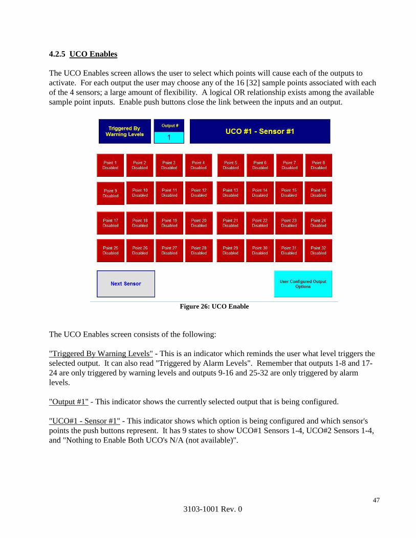
47
3103-1001 Rev. 0
4.2.5 UCO Enables
The UCO Enables screen allows the user to select which points will cause each of the outputs to
activate. For each output the user may choose any of the 16 [32] sample points associated with each
of the 4 sensors; a large amount of flexibility. A logical OR relationship exists among the available
sample point inputs. Enable push buttons close the link between the inputs and an output.
Figure 26: UCO Enable
The UCO Enables screen consists of the following:
"Triggered By Warning Levels" - This is an indicator which reminds the user what level triggers the
selected output. It can also read "Triggered by Alarm Levels". Remember that outputs 1-8 and 17-
24 are only triggered by warning levels and outputs 9-16 and 25-32 are only triggered by alarm
levels.
"Output #1" - This indicator shows the currently selected output that is being configured.
"UCO#1 - Sensor #1" - This indicator shows which option is being configured and which sensor's
points the push buttons represent. It has 9 states to show UCO#1 Sensors 1-4, UCO#2 Sensors 1-4,
and "Nothing to Enable Both UCO's N/A (not available)".
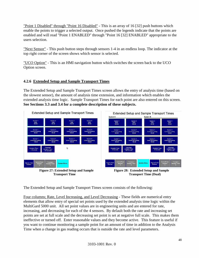
48
3103-1001 Rev. 0
"Point 1 Disabled" through "Point 16 Disabled" - This is an array of 16 [32] push buttons which
enable the points to trigger a selected output. Once pushed the legends indicate that the points are
enabled and will read "Point 1 ENABLED" through "Point 16 [32] ENABLED" appropriate to the
users selection.
"Next Sensor" - This push button steps through sensors 1-4 in an endless loop. The indicator at the
top right corner of the screen shows which sensor is selected.
"UCO Option" - This is an HMI navigation button which switches the screen back to the UCO
Option screen.
4.2.6 Extended Setup and Sample Transport Times
The Extended Setup and Sample Transport Times screen allows the entry of analysis time (based on
the slowest sensor), the amount of analysis time extension, and information which enables the
extended analysis time logic. Sample Transport Times for each point are also entered on this screen.
See Sections 3.3 and 3.4 for a complete description of these subjects.
Figure 27: Extended Setup and Sample Figure 28: Extended Setup and Sample
Transport Time Transport Time (Dual)
The Extended Setup and Sample Transport Times screen consists of the following:
Four columns; Rate, Level Increasing, and Level Decreasing - These fields are numerical entry
elements that allow entry of special set points used by the extended analysis time logic within the
MultiGard 5000 unit. All set point values are in engineering units and are entered for rate,
increasing, and decreasing for each of the 4 sensors. By default both the rate and increasing set
points are set at full scale and the decreasing set point is set at negative full scale. This makes them
ineffective or turned off. Enter reasonable values and they become active. This feature is useful if
you want to continue monitoring a sample point for an amount of time in addition to the Analysis
Time when a change in gas reading occurs that is outside the rate and level parameters.

49
3103-1001 Rev. 0
"Analysis Time" - This numerical entry element is the analysis time and is defaulted to 90 seconds
and has a valid entry range of 10-300 seconds. The slowest responding of the 4 sensors attached to
the MultiGard 5000 system determines the appropriate value for this entry.
"Extended Analysis Time" - This numerical entry element is the extended time the user requires
when any of the extended analysis time conditions (rate, increase, decrease) become true. By default
it is set to zero seconds and has an entry range of 0-180 seconds.
"Step to Point #" - This push button sequentially steps through all point numbers for the purpose of
viewing or entering the transport times per point.
"Select Point #:" - This numerical entry element allows direct entry of a point number for the purpose
of viewing or entering a sample transport time.
"Transport SMPL Time:" - This numerical entry element is the sample transport time for the selected
point. By default all transport times are zero and have an entry range of 0-300 seconds.
"System Menu" – An HMI navigation button which switches the screen back to the System Setup
Menu.
4.2.7 Sequencer Point Bypass
The Point Bypass screen allows the user to stop the sampling of any of the available points in the
MultiGard 5000 System. This is necessary when all available points are not being used or they are
temporarily taken out of service.
NOTE: Bypassing a point (eliminating a point from the sampling sequence) that has a sample or
bypass flow loss indication, will lead to a situation where the trouble condition cannot be cleared.
The MultiGard 5000 unit must access the line in question to determine that the fault condition has
been corrected whereby the CONDITION ACKNOWLEDGE button may be used to return the unit to
the normal operating state.System
Figure 29: Point Bypass Figure 30: Point Bypass (Dual)

50
3103-1001 Rev. 0
The Point Bypass screen consists of the following:
"Adjacent Steps Cannot Be Duplicates!" - This is a normally invisible indicator which warns of
adjacent steps being the same. This condition can be generated by the use of the point bypass and
point order features. This condition is possible when the user entered point order (see Section 4.2.8)
sets up a situation where the same point is sampled more than once in a single sequencer loop.
Bypassing the point(s) in between creates this invalid condition. When this indicator is visible no
point bypass pattern updates are possible until the condition is corrected.
"Point 1 Active" through "Point 16 Active" - An array of 16 [32] push buttons that will bypass the
indicated point. When pushed to bypass a point the button reads "Point 1 Bypassed";
"Discard Changes" - This push button clears all point bypass changes just made and restores
everything to that currently running in the system. Note that this button operates as stated only
before the "Apply Changes" (see below) push button is used.
"At Least 2 Points Must Be Active!" - This normally invisible indicator appears if less than two
points are active. The system design requires that any 2 points must be active as a minimum.
"Bypass Pattern is Current" - This push button indicates whether the sequencer point bypass pattern
is current or different than that running in the sequencer. When this button flashes "Apply Changes"
the user should press it after all desired changes have been made. This restarts the sequencer with the
new point bypass selections implemented.
"System Menu" – An HMI navigation button which switches the screen back to the System Setup
Menu.
4.2.8 Sequencer Point Order
All MultiGard 5000 sequencers contains 32 steps which always runs truly sequential; step 1 through
step 32, back to step 1, etc. This is true regardless of how many physical sample points MultiGard
5000 unit is configured to have. When the physical sample point count is less than 32 it is possible
to sample a specific point more than once per sequencer loop. User defined point order is
accomplished by use of the Point Order screen and allows the flexibility to accommodate a variety of
sampling schemes.
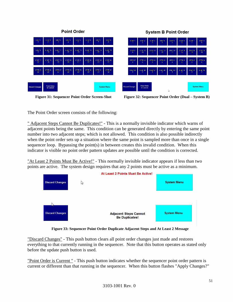
51
3103-1001 Rev. 0
Figure 31: Sequencer Point Order Screen-Shot Figure 32: Sequencer Point Order (Dual – System B)
The Point Order screen consists of the following:
" Adjacent Steps Cannot Be Duplicates!" - This is a normally invisible indicator which warns of
adjacent points being the same. This condition can be generated directly by entering the same point
number into two adjacent steps; which is not allowed. This condition is also possible indirectly
when the point order sets up a situation where the same point is sampled more than once in a single
sequencer loop. Bypassing the point(s) in between creates this invalid condition. When this
indicator is visible no point order pattern updates are possible until the condition is corrected.
"At Least 2 Points Must Be Active!" - This normally invisible indicator appears if less than two
points are active. The system design requires that any 2 points must be active as a minimum.
Figure 33: Sequencer Point Order Duplicate Adjacent Steps and At Least 2 Message
"Discard Changes" - This push button clears all point order changes just made and restores
everything to that currently running in the sequencer. Note that this button operates as stated only
before the update push button is used.
"Point Order is Current " - This push button indicates whether the sequencer point order pattern is
current or different than that running in the sequencer. When this button flashes "Apply Changes?"
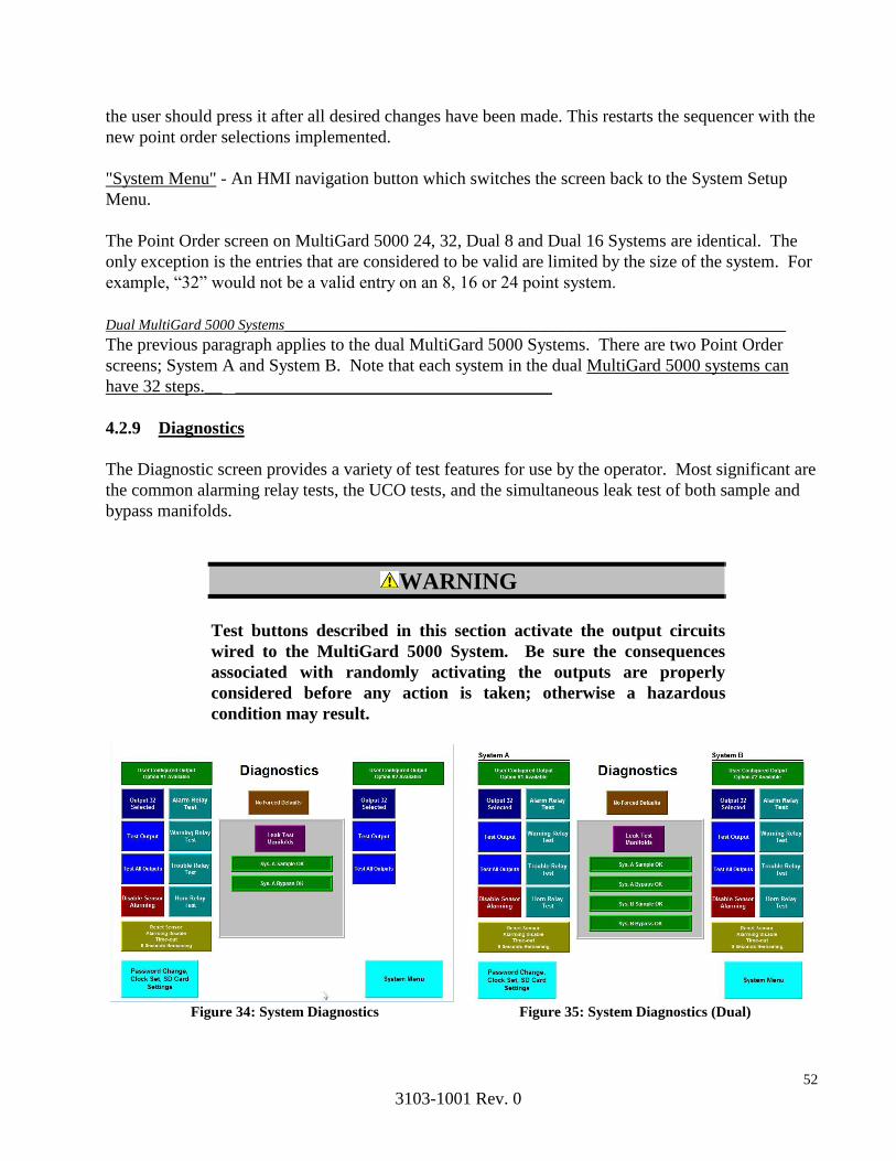
52
3103-1001 Rev. 0
the user should press it after all desired changes have been made. This restarts the sequencer with the
new point order selections implemented.
"System Menu" - An HMI navigation button which switches the screen back to the System Setup
Menu.
The Point Order screen on MultiGard 5000 24, 32, Dual 8 and Dual 16 Systems are identical. The
only exception is the entries that are considered to be valid are limited by the size of the system. For
example, “32” would not be a valid entry on an 8, 16 or 24 point system.
Dual MultiGard 5000 Systems_________________________________________________________
The previous paragraph applies to the dual MultiGard 5000 Systems. There are two Point Order
screens; System A and System B. Note that each system in the dual MultiGard 5000 systems can
have 32 steps.__ ____________________________________
4.2.9 Diagnostics
The Diagnostic screen provides a variety of test features for use by the operator. Most significant are
the common alarming relay tests, the UCO tests, and the simultaneous leak test of both sample and
bypass manifolds.
WARNING
Test buttons described in this section activate the output circuits
wired to the MultiGard 5000 System. Be sure the consequences
associated with randomly activating the outputs are properly
considered before any action is taken; otherwise a hazardous
condition may result.
Figure 34: System Diagnostics Figure 35: System Diagnostics (Dual)

53
3103-1001 Rev. 0
The Diagnostics screen consists of the following:
First and Fourth columns; "UCO#1 N/A" through "Test All Outputs" - The first column handles the
UCO#1 option and the fourth column handles the UCO#2 option. Both sets of controls operate
identically. The indicators "UCO#1 N/A" and "UCO#2 N/A" indicate that the UCO options are not
available. When they are available the indicators read "UCO#1" and "UCO#2".
The "Selected Output:" indicators show what output is selected for test. The "Select Output" push
button sequentially steps through all of the 32 outputs. The "Test Output" push button will activate
the selected output for as long as the operator holds the button. The "Test All Outputs" push button
will trigger a sequential test of all 32 outputs. Each one will be activated for one half second.
Second Column; "Alarm Relay Test" through "Horn Relay Test" - The array of 4 push buttons allow
the operator to test all of the common alarming relay outputs separately. The outputs are activated
for as long as the button is pushed.
"No Forced Defaults" - When the push button indicator is visible as shown system operation is
normal. When the Compactlogix processor loads the factory default program from the SD card, this
push button indicator appears flashing as "-DEFAULTS- Reset Flag". When this happens, any user
entered parameters are lost and the MSA factory defaults are loaded. See section 4.2.10 for
instructions on how to restore saved user settings from the SD card. The processor restoring from
factory defaults is classified as a trouble condition and the source of the processor action must be
determined. The only normal cause for this is battery failure followed by power being turned off long
enough for internal capacitors to discharge. This event should be rare assuming the MultiGard 5000
system is powered up most of the time while in service. This condition flag can be reset by pressing
this button.
WARNING
If “-DEFAULTS- Reset Flag” indicator flashes, all user entered
parameters are lost and the MSA factory defaults are restored.
Immediate action is required! The cause of this condition must be
determined and corrected. This condition requires the operator to
manually re-enter all user configured parameters to restore
MultiGard 5000 unit to its most recent desired operation. If no
action is taken the MultiGard 5000 unit will remain in default
operation with only common alarming as defined in Section 1. This
results in operation identical to the initial delivery of MultiGard
5000 unit.
"Reset Sensor Alarming Disable Time-Out" - This push button resets the sensor alarming disable
time-out timer if it is necessary to extend the function. The time remaining until alarming is restored
is shown on this button.

54
3103-1001 Rev. 0
"Disable Sensor Alarming" - This push button disables all sensor alarming by operator control and is
intended for service purposes. A time-out timer will automatically enable alarms after 30 minutes
for safety reasons. Note that the operator should immediately enable the alarming when the reason to
disable it is no longer valid.
"Password Change, Clock Set, SD Card, Settings" - This is an HMI navigation button which
switches the screen to the Password Change and Clock Sets screen.
Center indicators and "Leak Test Manifolds" - The push button in the center triggers the
simultaneous leak test of both the sample and bypass manifolds. The legend and indicators on either
side of the button shows the results of the test. As shown the sample manifold "Sys. A Sample OK"
and the bypass manifold "Sys. A Bypass OK". These indicators show " Leaks Detected" when leaks
are found.
"System Menu" - An HMI navigation button which switches the screen back to the System Setup
Menu.
4.2.10 Password Change, Clock Set, and SD Card Setup
The Password Change, Clock Set and SD Card Setup screen allows the operator to change the
MultiGard 5000 System password and set the clock in the touchscreen display. This screen is also
used to read and write user settings to and from the PLC’s SD card.
Figure 36: Password, Clock and SD Card Setup Screen-Shot
55
3103-1001 Rev. 0
The Password Change, Clock Set and SD Card Setup screen consists of the following:
"Month" through "Seconds" - An array of 6 numerical entry elements which allows the display date
and time to be set.
"Change Password To" and "Confirm Password Change" - The two numerical entry elements allow
entry of a custom user password to be installed into the MultiGard 5000 System. The password can
be up to 5 digits long. Enter the same number into both entries. If the entries are different both
numbers will be visible and the old password is still in effect. Once the same numbers are entered in
both entries the new password becomes effective and zeros are displayed in these entries.
NOTE: The user must record the current password in a safe, secured location. If forgotten there is
no way to view it!
"Restore From: Factory Defaults" - This button toggles the profile from which the user wants to
restore. There are two options. The default setting is to restore from Factory Defaults which returns
the entire Multigard System program to the state as it was supplied from the factory. This means all
user stored data including but not limited to alarm levels, sequence patterns, calibration data, timers,
user configured output settings and passwords will be lost. Pressing this button once will toggle the
restore location to “User Settings”. Before a user can restore from the User Settings profile, a saved
User Settings profile needs to be created. See "Save User Settings to SD" below for instructions on
creating a User Settings Profile. The Factory Defaults Profile is created at the factory and cannot be
altered by the user. In the event of a memory fault, the Multigard is configured to automatically
restore from the Factory Defaults Profile. If this occurs, indication will be given to the user as
described in Section 4.1.1 under "User Settings Stored"
"Start Restore" - This button initiates the restore process once the desired restore profile has been
selected as described above. When pressed, the button will display “Restoring” for the duration of
the process. It will return to its original state when the process has stopped. Check the SD status
indicators at the bottom center of the screen to determine the result of the restore.
"Save User Settings to SD" - This button initiates the saving of user entered parameters to the SD
card. When pressed, the button will display “Saving” for the duration of the process. It will return to
its original state when the process has stopped. Check the SD status indicators at the bottom center
of the screen to determine the result of the restore. If a user wishes to restore the Multigard 5000 to
its complete user configured state after a memory fault has occurred, it is critical that the user
settings be saved via this button after the Multigard 5000 has been setup to the user’s needs. Failure
to save user entered parameters after setup will only allow for the system to be restored to factory
defaults. A “User Settings” profile must be saved using the above described method before a user
can restore from this profile. Attempting to restore from “User Settings” without first creating a
“User Settings” profile will result in an unsuccessful load and SD card errors being displayed at the
bottom center of the screen.

56
3103-1001 Rev. 0
"Last SD Card Read OK" - This indicator displays the status of the last attempted SD card read as
initiated by the “Restore From: Factory Defaults/User Settings” button. If an unsuccessful attempt
results, the indicator will display “SD Card Read Fault”. Typical causes for this are either that the
SD card is missing for the Compactlogix slot, the SD Card is corrupt, or the User Settings Profile has
not been created on the SD card yet. Attempting to create a User Settings Profile via the “Save User
Settings to SD” and restoring from that profile may clear the “SD Card Read Fault”.
"Last SD Card Write OK" - This indicator displays the status of the last attempted SD card write as
initiated by the “Save User Settings to SD” button. If an unsuccessful attempt results, the indicator
will display “SD Card Write Fault”. Typical causes for this are either that the SD card is missing for
the Compactlogix slot, the SD Card is corrupt.
"SD Card Integrity OK" - This indicator displays the status of the data integrity on the SD Card.
After each save to the SD card, the processor checks the characteristics of the written data to ensure
proper formatting. In the event corrupt data the indicator will display SD Card Integrity Error”.
Typical causes for this are either that the SD card is missing for the Compactlogix slot or the SD
Card is corrupt.
"Diagnostics" - This is an HMI navigation button which switches the screen back to Diagnostics.
"System Menu" - A an HMI navigation button which switches the screen back to the System Setup
Menu.

57
3103-1001 Rev. 0
4.2.11 Auto Standardization Setup
The auto standardization Setup screen provides for enabling the timed feature, entry of the number of
days, and 3 specific times for timed auto standardization. The zero gas concentrations and span gas
concentrations for each sensor are also entered here.
Figure 37: Auto Standardization Setup Figure 38: Auto Standardization Setup (Dual)
The auto standardization Setup screen consists of the following:
"Days" - A numerical entry element that allows entry of the number of days between auto
standardization. It defaults to 30 days and has a valid entry range of 0-180 days.
"#1 Hours" and "#1 Minutes" - Two numerical entry elements that allows a specific time to be
entered for auto standardization. This is the first of three time entries.
"#2 Hours" and "#2 Minutes" - Two numerical entry elements that allows a specific time to be
entered for auto standardization. This is the second of three time entries.
"#3 Hours" and "#3 Minutes" - Two numerical entry elements that allows a specific time to be
entered for auto standardization. This is the third of three time entries.
One, two, or three auto standardization per day are possible by adjusting the time entries as follows:
When all three times are equal there is one auto standardization per day. When two of the three
times are equal there are two auto standardizations per day. When none of the three times are equal
there are three auto standardizations per day.
"Timed ASTD DISABLED" - This is a push button that enables timed auto standardization. By
default it is disabled. It reads "Timed ASTD ENABLED" when pressed.
"Sensor 1 Zero Gas" through "Sensor 4 Zero Gas" - These four numerical entry elements allow the
zero gas concentrations for each sensor to be entered. These values come directly from the gas

58
3103-1001 Rev. 0
cylinder labels and are entered in engineering units. They default to zero and will most likely always
be zero unless a special application is implemented.
NOTE: Every time the gas cylinders are replaced the new values must be entered to maintain auto
standardization accuracy if the new cylinders are of a different concentration value.
"Sensor 1 Span Gas" through "Sensor 4 Span Gas" - These four numerical entry elements allow the
span gas concentrations for each sensor to be entered. These values come directly from the gas
cylinder labels and are entered in engineering units.
"Sensor 1 A.S. Disabled" – This button toggles between the selectable options for which Span Port
to use during an auto standardization for Sensor 1. When in the “Disabled” selection, an auto
standardization will not occur on Sensor 1. “Span Port 1 Selected for Sensor 1 will turn on auto
standardization for Sensor 1 and assign physical Span Port 1 on the side of the enclosure for the
introduction of span gas during auto standardization. “Span Port 2 Selected for Sensor 1 will turn on
auto standardization for Sensor 1 and assign physical Span Port 2 on the side of the enclosure for the
introduction of span gas during auto standardization.
"Sensor 2 A.S. Disabled" – This button toggles between the selectable options for which Span Port
to use during an auto standardization for Sensor 2. When in the “Disabled” selection, an auto
standardization will not occur on Sensor 2. “Span Port 1 Selected for Sensor 2 will turn on auto
standardization for Sensor 2 and assign physical Span Port 1 on the side of the enclosure for the
introduction of span gas during auto standardization. “Span Port 2 Selected for Sensor 2 will turn on
auto standardization for Sensor 2 and assign physical Span Port 2 on the side of the enclosure for the
introduction of span gas during auto standardization.
"Sensor 3 A.S. Disabled" – This button toggles between the selectable options for which Span Port
to use during an auto standardization for Sensor 3. When in the “Disabled” selection, an auto
standardization will not occur on Sensor 3. “Span Port 1 Selected for Sensor 3 will turn on auto
standardization for Sensor 3 and assign physical Span Port 1 on the side of the enclosure for the
introduction of span gas during auto standardization. “Span Port 2 Selected for Sensor 3 will turn on
auto standardization for Sensor 3 and assign physical Span Port 2 on the side of the enclosure for the
introduction of span gas during auto standardization.
"Sensor 4 A.S. Disabled" – This button toggles between the selectable options for which Span Port
to use during an auto standardization for Sensor 4. When in the “Disabled” selection, an auto
standardization will not occur on Sensor 4. “Span Port 1 Selected for Sensor 4 will turn on auto
standardization for Sensor 4 and assign physical Span Port 1 on the side of the enclosure for the
introduction of span gas during auto standardization. “Span Port 2 Selected for Sensor 4 will turn on
auto standardization for Sensor 4 and assign physical Span Port 2 on the side of the enclosure for the
introduction of span gas during auto standardization.
NOTE: If all active sensors are set to “Disabled”, the auto standardization feature will be turned off
on the Multigard 5000 system. All correction factors will not be applied. This is helpful in a case
where gases used in the auto standardization process have run out and an auto standardization
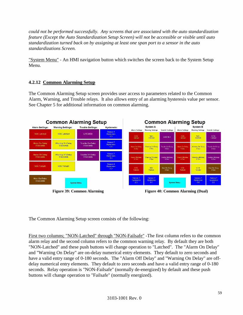
59
3103-1001 Rev. 0
could not be performed successfully. Any screens that are associated with the auto standardization
feature (Except the Auto Standardization Setup Screen) will not be accessible or visible until auto
standardization turned back on by assigning at least one span port to a sensor in the auto
standardizations Screen.
"System Menu" - An HMI navigation button which switches the screen back to the System Setup
Menu.
4.2.12 Common Alarming Setup
The Common Alarming Setup screen provides user access to parameters related to the Common
Alarm, Warning, and Trouble relays. It also allows entry of an alarming hysteresis value per sensor.
See Chapter 5 for additional information on common alarming.
Figure 39: Common Alarming Figure 40: Common Alarming (Dual)
The Common Alarming Setup screen consists of the following:
First two columns; "NON-Latched" through "NON-Failsafe" -The first column refers to the common
alarm relay and the second column refers to the common warning relay. By default they are both
"NON-Latched" and these push buttons will change operation to "Latched". The "Alarm On Delay"
and "Warning On Delay" are on-delay numerical entry elements. They default to zero seconds and
have a valid entry range of 0-180 seconds. The "Alarm Off Delay" and "Warning On Delay" are off-
delay numerical entry elements. They default to zero seconds and have a valid entry range of 0-180
seconds. Relay operation is "NON-Failsafe" (normally de-energized) by default and these push
buttons will change operation to "Failsafe" (normally energized).
60
3103-1001 Rev. 0
Third column; "Latched" through "Trouble Off Delay" - This column refers to the common trouble
relay parameters. By default trouble operates "Latched" and the push button will switch it to "NON-
Latched" operation. The "Trouble On Delay" is an on-delay numerical entry element that defaults to
zero seconds and has a valid entry range of 0-180 seconds. The "Trouble Off Delay" is an off-delay
numerical entry element that defaults to zero seconds and has a valid entry range of 0-180 seconds.
The trouble relay is always Failsafe (normally energized) and cannot be changed.
"Horn On Delay" - This horn on-delay numerical entry element defaults to zero seconds and has a
valid entry range of 0-180 seconds.
"Sensor 1 Hysteresis" through "Sensor 4 Hysteresis" - These four numerical entry elements allow
entry of a hysteresis value in engineering units for each sensor. These values apply to trouble,
warning and alarm level detection across all points associated with each sensor.
"System Menu" - An HMI navigation button which switches the screen to the System Setup Menu.
61
3103-1001 Rev. 0
5. Common Alarming
Four outputs (alarm, warning, trouble and horn) are provided for common alarming. The function of
these relays is to indicate the Alarm Status of the MultiGard 5000 System. The alarm status of each
line per sensor is indicated in the Status column of each of the Gas Levels and Alarming Status
display screens (see section 4.1.2).
Dual MultiGard 5000 Systems____________________________________________________________
On the dual MultiGard 5000 Systems there are two sets of four outputs; one set for System A and the
other set for System B. Functionality is identical except as noted later in this section.
5.1 Alarm
The alarm set point per sensor per point can be entered in the Set Points display screen (see section
4.2.3). The alarm relay may be configured as fail-safe (normally energized) or non-fail safe (normally
de-energized) in the Common Alarming Set-up display screen (see section 4.2.12).
Exceeding an alarm level will cause the MultiGard 5000 unit to indicate an alarm level, alter the
state of the alarm relay and energize the horn relay. The Acknowledge Horn button on the overview
screen will promptly de-energize the horn relay. Once a latched alarm has cleared, the Condition
Acknowledge button can be used to return the unit to the normal operating state.
5.2 Warning
The warning set point per sensor per point can be entered in the Set Points display screen (see section
4.2.3). The warning relay may be configured as fail-safe (normally energized) or non-fail safe
(normally de-energized) in the Common Alarming Set-up display screen (see section 4.2.12).
Exceeding a warning level will cause the MultiGard 5000 System to indicate a warning level, alter
the state of the warning relay and pulse the horn relay at a 50% duty cycle (2 sec. energized, 2 sec.
de-energized). The Acknowledge Horn button on the overview screen will promptly de-energize the
horn relay and inhibit the pulsing action. Once a latched warning has cleared, the Condition
Acknowledge button can be used to return the unit to the normal operating state.
5.3 Trouble
The trouble set point is used to detect below scale sensor drift and its value can be entered per
sensor per point in the Set Points display screen (see section 4.2.3). The Trouble relay is always
configured to be fail-safe (normally energized) and may not be changed. Exceeding a trouble level
will cause the MultiGard 5000 System to indicate a trouble, de-energize the trouble relay and pulse
the horn relay at a 20% duty cycle (1 sec. energized, 4 sec. de-energized). The Acknowledge Horn
button on the overview screen will promptly de-energize the horn relay and inhibit the pulsing
action.
The Condition Acknowledge button can be used to return the unit to the normal operating state once

62
3103-1001 Rev. 0
the trouble condition has been cleared. The horn will resume pulsing immediately if another trouble
condition occurs or, in 30 minutes if the trouble condition is not cleared. The only exception is a
trouble condition indicating an auto standardization low level tolerance has been exceeded. Once
acknowledged, the horn relay will not re-activate unless triggered by some other condition.
Other trouble conditions as shown in Table 5.3 will also result in a trouble indication similar to the
above.
Table 5.3: MultiGard 5000 Trouble Conditions
Sensor drift below scale
PIR not ready
Flow fail, sample manifold
Auto-standardize low tolerance exceeded
Flow fail, bypass manifold
Auto-standardize high tolerance exceeded
Sample manifold failed diagnostic leak test
No calibration/purge gas
Bypass manifold failed diagnostic leak test
Loss of memory, default parameters forced
____________________________________________________________________________ Dual MultiGard 5000 Systems
On the dual MultiGard 5000 systems, the “Loss of memory, default parameters forced” trouble
conditions are common to the entire assembly and are indicated on System A. They are not
duplicated on System B
____________________________________________________________________________
WARNING
Wire Trouble Relay to operate an externally powered device (horn,
beacon, computer, PLC, etc.) using the common and normally closed
contacts for fail-safe operation on loss of power. The Trouble Relay
is an important safety device and failure to wire as specified may
result in no indication should gas detection system malfunction
and/or become disabled.
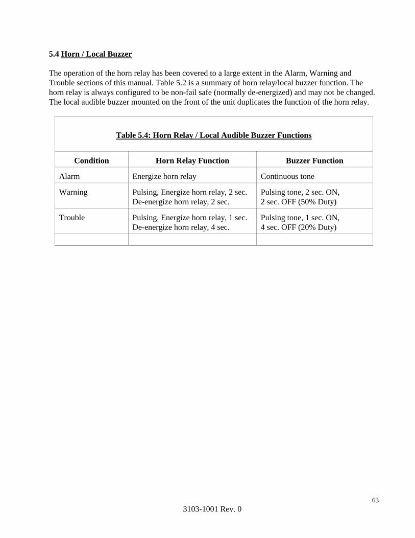
63
3103-1001 Rev. 0
5.4 Horn / Local Buzzer
The operation of the horn relay has been covered to a large extent in the Alarm, Warning and
Trouble sections of this manual. Table 5.2 is a summary of horn relay/local buzzer function. The
horn relay is always configured to be non-fail safe (normally de-energized) and may not be changed.
The local audible buzzer mounted on the front of the unit duplicates the function of the horn relay.
Table 5.4: Horn Relay / Local Audible Buzzer Functions
Condition
Horn Relay Function
Buzzer Function Alarm
Energize horn relay
Continuous tone
Warning
Pulsing, Energize horn relay, 2 sec.
De-energize horn relay, 2 sec.
Pulsing tone, 2 sec. ON,
2 sec. OFF (50% Duty) Trouble
Pulsing, Energize horn relay, 1 sec.
De-energize horn relay, 4 sec.
Pulsing tone, 1 sec. ON,
4 sec. OFF (20% Duty)
64
3103-1001 Rev. 0
6. Maintenance
6.1 General Maintenance
A regular schedule of maintenance will help ensure continued operation of the MultiGard 5000 Gas
Sampling System. Calibration of sensor(s)/analyzer(s) should occur promptly after the indication of a
“sensor out of tolerance” event and otherwise periodically to ensure proper operation.
WARNING
The only absolute method to ensure proper operation of a
sensor/analyzer is to check it with a known concentration of gas
for which it has been calibrated. Consequently, calibration checks
must be included as part of the routine inspection of the system.
At regular intervals, depending on cleanliness of the area being monitored, all particulate filters
should be checked and changed if necessary. All sample lines should be checked for leaks to avoid
sample dilution and lower than actual erroneous readings. Exhaust lines should be checked for
obstruction.
Upon indication of any trouble by the MultiGard 5000 Gas Sampling System, the cause should be
determined and corrected promptly. The trouble shooting section may help in determining possible
causes of the trouble indication.

65
3103-1001 Rev. 0
6.2 Trouble Shooting Guide
Table 6.2 is provided as a general guide for first level trouble shooting. Conditions not correctable by
this guide should be referred to MSA.
Indication Possible Cause Corrective Action
Power not connected to unit Wire in accordance with field
wiring diagram
System circuit breaker in off
position
Place system circuit breaker
into the On position
System DC power supply faulted Check DC power supply and
replaced if necessary
Power not connected to unit Wire in accordance with field
wiring diagram
System circuit breaker in off
position
Place system circuit breaker
into the On position
System DC power supply faulted Check DC power supply and
replaced if necessary
Power not connected to unit Wire in accordance with field
wiring diagram
Pump circuit breaker in off
position
Place pump circuit breaker
into the On position
Pump faulted Replace pump
Sample line blocked or kinked Remove obstruction from line
Saturated end of line filter Replace end of line filter
Pump not operational Replace pump
Faulted sample/bypass solenoid
valve
Replace defective valve
Calibration gas cylinder empty Replace gas cylinder
Gas flow set incorrectly Adjust flow per section 3.2
Faulted solenoid on calibration
manifold
Replace calibration manifold
Sensor drifted out of tolerance Calibrate sensor
Incorrect calibration gas value
entered in Auto Standard Setup
Screen
Check and enter correct span
gas value
PIR in trouble Correct PIR trouble
PIR in start up sequence Allow PIR to warm up and
switch to ready mode (About
60 sec from applying power)
Sensor out of tolerance Calibrate sensor
PIR in start up sequence Allow PIR to warm up and
switch to ready mode (About
60 sec from applying power)
"Auto Standard Not
Performed" indicator
flashing
An auto standardization has not
been successfully performed on
the system
Manually start auto
standardization
"Alarming Disabled Auto
Standard Upper Range Out
of Tolerance" indicator
flashing
Sensor drifted out of tolerance Calibrate sensor and manually
run auto standardization
"Defaults Forced"
indicator flashing
Processor has booted from the SD
Card due to memory corruption
Contact MSA for diagnosis or
attempt to load User Settings
Profile
Pump diaphragm has ruptured Replace pump
Sample manifold valve or
plumbing contains leaks
Replace leaking component
Bypass manifold valve or plumbing has leaksReplace leaking component
Flow switch malfunctioning Clean or replace flow switch
"Leaks Detected" indicator
flashing
Flow Status and
Calibration bars flashing
Calibration bars flashing
"PIR Faulted or Warming
Up" indicator flashing
Sensor trouble
Table 6.2 Trouble Shooting Guide
No power to view screen
No power to Compactlogix
Pump not operational
Flow Status Bar Flashing

66
3103-1001 Rev. 0
6.3 Replacement Parts
WARNING
Use only genuine MSA replacement parts when performing any maintenance procedures
provided in this manual. Failure to do so may seriously impair the MultiGard 5000 System
performance. Repair or alteration of the MultiGard 5000 System, beyond the scope of these
maintenance instructions or by anyone other than an authorized MSA service person, could
cause the product to fail to perform as designed and persons who rely on this product for
their safety could sustain personal injury or death.
Refer to the MultiGard 5000 System drawings for replacement parts. Each system is delivered with
a unique set of drawings per order.
The MultiGard 5000 System Instruction, Section 4 (Manufacturers Data Sheets), includes complete
vendor instructions and parts breakout drawings for the pump(s) used in this MultiGard 5000 system.
Other items appropriate to a specific order may also be included in this section.
Address any parts inquiries to:
Mine Safety Appliances Company
1000 Cranberry Woods Drive
Cranberry Township, PA 16066
Or call toll free, 1-800-MSA-INST
67
3103-1001 Rev. 0
Sensors 1 and 2 are on System A, sensors 3 and 4 are on System B. A User Configured
Output may be triggered from any combination of the 4 sensors or lines available.
7. User Configured Outputs Option
Two options of User Configured Outputs are offered with the MultiGard 5000 System. Each option
is 32 outputs for a maximum of 64 User Configured Outputs. These outputs may either take the form
of solid state outputs or form C relay contacts. Refer to the specifications section of this manual for
technical data on the User Configured Outputs. User Configured Outputs are a factory installed
option as both hardware and software modifications are required.
7.1 Planning Matrix
Prior to configuring the outputs, it is recommended that the User Configured Outputs Planning
Matrix (form BSK 3103-24) be completed for each option. This process will clarify functionality;
simplify the data entry process and aid in trouble shooting logic errors. This form should be filled
without regard to the MultiGard 5000 System. Only facility functions should be considered while
completing this form. The planning matrix should indicate if it applies to option #1 or #2, solid state
outputs or form C contacts by marking the appropriate check box.
7.1.1 Output Trigger
For each of the two user configured options, outputs 1 to 8 and outputs 17 to 24, are triggered by
warning levels. Outputs 9 to 16 and outputs 25 to 32, are triggered by alarm levels. For each output,
indicate the sensor(s) and line(s) that will trigger that output by marking the corresponding box with
an X. For an 8 [24] point sequencer, lines 9 to 16 [25 to 32] are not applicable.
Dual MultiGard 5000 Systems
7.1.2 Output Characteristics
Each output may further be defined to have an On delay or an Off delay (in seconds). Each output
may be configured as fail safe (normally energized), or non-fail safe (normally de-energized) to
activate on loss of power. Each output may be further defined to activate in the steady mode or pulse
1 sec. ON, 1 sec. OFF.
Each User Configured Output may be configured so that it can be acknowledged. This feature allows
for the silencing of audible devices wired to these outputs.
Once an operator has acknowledged an output, it will only reactivate under one of the following
conditions:
1. A warning or alarm condition occurs after all conditions that are associated with that User
Configured Output have returned to normal. On outputs that are triggered by multiple points/sensors,

68
3103-1001 Rev. 0
once acknowledged, another condition will not reactivate the output.
2. Thirty minutes has elapsed since the User Configured Output was acknowledged by the
operator and the conditions that caused that event are still present.
This operation is in contrast to the Common Alarms, where each new condition causes a reactivation
of the warning or alarm.
A Warning or Alarm indication by the MultiGard 5000 Gas Sampling System requires
immediate action by the operator. Failure to do so may lead to serious injury or death. Once
an operator has acknowledge a User Configured Output, It is imperative that immediate
action be taken to determine the source of this condition, take remedial action and continue to
monitor the Gas Level Screens until all levels return to normal.
NOTE: Unless specifically requested otherwise, the MultiGard 5000 unit is shipped without defining
the functions of the User Configured Outputs. Under those conditions, none of the outputs will
activate until they are configured in the field.
WARNING
69
3103-1001 Rev. 0
7.2 Data Entry
Upon completion of the Planning Matrix, the data can be entered into the MultiGard 5000 System
using the User Configured Outputs data screen (see section 4.2.4). Two flags are used to indicate if
option #1 and/or option #2 have been installed and are available for use. The header will indicate the
option number being programmed.
For each option, the UCO’s are numbered 1 to 32. The "ENTER OUTPUT TO CONFIGURE"
button may be used to select the desired output. At this time, the data entered in the Planning Matrix
for On delay and Off delay may be entered if it is required to be other than the default value of 0
seconds. The Fail-Safe / Non Fail Safe and Steady / Pulse buttons may be toggled to the required
state. Then the “UCO Point Enables” button may be used to move to the UCO Point Enables display
screen (see section 4.2.5). Flags are used to indicate if the output is triggered by a warning or an
alarm level, the UCO number, the UCO option number, and the sensor number. Enable each
point/line number to match the entries on the Planning Matrix. Use the "Next Sensor" button to
scroll to the next page and enter the configurations for sensors #2, 3 and 4 if applicable. Use the
"UCO Option" button to return to the UCO display screen.
Repeat the procedure for all other UCO outputs indicated on the Planning Matrix.
7.3 Functionality Testing
WARNING
User Configured Outputs must be tested to verify that actual
functionality is identical to intended functionality as indicated in the
UCO Planning Matrix. Failure to verify setup may result in system
performance other than expected.
CAUTION
Do not connect any system controlled process shut down circuits
until the system has been function checked, calibrated and is ready
for normal operation. False alarms may occur if this connection is
done before full system startup is completed

70
3103-1001 Rev. 0
To test the functionality of the User Configured Outputs, the conditions that trigger these outputs
must be simulated. Place the unit in manual mode and step to line/point #1. Use the sensor zero
adjustment (see sensor manual) to artificially create an upscale reading in excess of the preset
warning level for sensor #1. Verify that the conditions triggered by a warning on line/point #1 for
sensor #1 as indicated in the Planning Matrix do actually occur. Repeat this procedure for all other
line/point numbers. Use the sensor zero adjustment (see sensor manual) to artificially create an
upscale reading in excess of the preset alarm level for sensor #1. Verify that the conditions triggered
by an alarm on line/point #1 for sensor #1 as indicated in the Planning Matrix do actually occur.
Repeat this procedure for all other line/point numbers. Reset the sensor output to zero. Verify that
the conditions triggered by either an alarm or a warning for line/point #1 for sensor #1 are no longer
indicated. Repeat this procedure for all other line/point numbers.
Repeat above procedure for sensors #2, 3 and 4 if applicable.
Follow with a calibration of all sensors.
8. MultiGard 5000 System Configuration
The MultiGard 5000 Gas Sampling Systems are configured both by the MSA factory and by the user
to obtain desired results. Factory parameters cannot under any circumstances be changed by the user.
All user parameters may be changed at any time and are secured by a password.
WARNING
Entering valid System Parameters is critical to proper system
operation. Incorrect entries may lead to a hazardous situation.
Contact MSA if you have any questions related to the MultiGard
5000 Gas Sampling System User Configured Parameters.
A summary of MultiGard 5000 System default parameters is provided upon shipment from MSA.
These documents describe the system delivered and are located in Section 1.

71
3103-1001 Rev. 0
8.1 MultiGard 5000 System Factory Configured Parameters
The factory parameters are derived from order entry information, the sensor complement in use, and
the results of applications engineering. This ensures proper system operation and integrity upon
delivery. All factory configured parameters are summarized below:
Mode of Operation (8, 16, & Dual 8 Point or 24, 32, & Dual 16 Point)
Analyzer(s) Ready Enable
Sensor Low Engineering Units (per input)
Sensor High Engineering Units (per input)
Sensor Scaling for Voltage (V) or Current (I) (per input)
Sensor Input Minimum V or I (per input)
Sensor Input Maximum V or I (per input)
Sensor Alarming Direction - Warning (per input)
Sensor Alarming Direction - Alarm (per input)
Sensor Type (per input)
Sensor Engineering Units (per input)
Auto Standardization (ASTD) Enable & Span Valve Selection (per input)
Low ASTD Tolerances (per input)
High ASTD Tolerances (per input)
ASTD Duration: Zero, Span1, Span2, & Purge
Enable Synthetic Span Gas Usage (per input)
Synthetic Span Gas Conversion Parameters (per input): slope (m) and intercept (b)
User Configured Output (UCO) Option #1 Enable
UCO Option #2 Enable
Version # for Logix Program
S/N, B-Job #, MTO Code, & End User's Name
Purge Operation? (per sensor)
Purge Valve Selection
Purge Set point (per sensor)
Purge Duration
Attached device combustible? (per sensor)
Combustible W&A Set point Limit (per sensor) per FMRC Regulations

72
3103-1001 Rev. 0
8.2 MultiGard 5000 System Secured User Configured Parameters
All user parameters are defaulted by MSA that produce a basic implementation of MultiGard 5000
System. Selected user configured parameters are preset by MSA appropriate to the customer order
(underlined below) to ensure a safe system immediately upon delivery. As the customer’s
application requirements change, all of these parameters can be altered without MSA's involvement.
This list also represents the parameters that are saved to the SD card when a “User Settings” profile
is created. All user changeable parameters are summarized below:
Change Password
Trouble (T), Warning (W), & Alarm (A) Set points (per point per sensor)
Sequencer Point Order
Sequencer Point Bypass
Transport Sample Time (per point)
Analysis Time (based on slowest sensor response)
Extended Analysis Time (EAT)
EAT Trigger - Rate (Engineering Units/Second) (per sensor)
EAT Trigger - Level Increasing (per sensor)
EAT Trigger - Level Decreasing (per sensor)
For Common Alarming:
Latched/Non-Latched - Trouble, Warning, & Alarm Relays
Fail-Safe/Non-Fail-Safe - Warning & Alarm Relays
On-Delays - Trouble, Warning, Alarm, & Horn Relays
Off-Delays - Trouble, Warning, & Alarm Relays
Alarming Hysteresis (per sensor)
Zero Gas in Use (common to all sensors)
Span Gases in Use (per sensor)
Timed ASTD Enable
Days Interval; Timed ASTD
Hours & Minutes for each of 3 ASTD's/Day
For Both UCO Options; Each consisting of 32 Outputs
(16 Warning Triggered & 16 Alarm Triggered):
On-delay
Off-delay
Fail-Safe/Non-Fail-Safe
Steady/Pulsed
Enables (Points 1-16 Available from Each Sensor)
Set Clocks: Compactlogix for ASTD & Display

73
3103-1001 Rev. 0
9. MultiGard 5000 System Remote Data Display (RDD) Option
9.1 Introduction
The MultiGard 5000 Remote Data Display (RDD) Option is a touch-screen that allows the viewing
of selected information contained in the MultiGard 5000 unit. The RDD communicates with the
MultiGard 5000 System via serial or over Ethernet.
A 10.4” color touch-screen version is standard for all MultiGard systems.
Throughout this chapter the RDD screens for MultiGard 5000 8/16 unit are shown in the figures.
Users of the MultiGard 5000 24/32 unit should note the following rules on using the same operator
manual:
The location of any item is in the same relative position across all screen sizes.
The same information content is provided on each screen across all screen sizes.
Wherever 16 points of information are shown in the figures, 32 points of
information will actually be seen on the screens in a similar format.
The phrases underlined and in quotes which lead to a description of an item still refer to the
figures. Any changes will be noted in the description (see next bullet).
In the item descriptions point ranges or references to system size may be specified which
match the figure. Substitute the numbers in brackets ( [] ) in place of those in the sentence.
Any exceptions to these rules will be discussed in the appropriate section.
Users of MultiGard 5000 Dual 8 and MultiGard 5000 Dual 16 Systems should note the following
rules on using the same operator manual:
The same information content is provided on each screen across all screen sizes and
across all models. The location of some items may be different between the single and
dual models.
Wherever dual MultiGard 5000 data is presented based on the number of sample points
the quantity will vary between 8 or 16 and be presented in a similar manner.
The phrases underlined and in quotes which lead to a description of an item still refer to
the original figures. In addition these items in the dual MultiGard 5000 Systems are
specifically labeled System A (SYS A) and System B (SYS B) to distinguish between
the two systems. Items common to the overall assembly do not use this designation.

74
3103-1001 Rev. 0
Sample text related to the dual MultiGard Systems.
This information can be ignored by users of single MultiGard Systems.
When explicit labeling is not used the header text System A: and System
B: are used. Everything directly under these headers then applies to the
system as labeled.
The relative position of System A grouped data is on the left. The relative position of
System B grouped data is on the right. Data common the overall assembly is located in
the center or where space permits.
Any special notes and exceptions to these rules will be discussed in the appropriate
section and will be visually distinguished by the text box style as shown below.
Dual MultiGard 5000 Systems
The graphical style used in the RDD is identical to the MultiGard 5000 touchscreen shown in
Chapter 4 of this manual.
All MultiGard 5000 RDD touch-screen displays have a screen saver feature enabled. The screen will
turn off after 30 minutes of touch inactivity. After it turns off, the first touch will restore the screen
to normal operation.
9.2 Installation
Refer to the RDD installation drawing provided for the installation and wiring of your remote data
display. The drawing provides information on cut out size required for panel mounting the RDD,
power requirements of the RDD and the type and correct wiring of the communication cable.
9.3 Operation
The RDD is intended to provide an operator with information about the gases being monitored and
the basic operation of the MultiGard 5000 System. It is a view only device and does not allow
changing any of the user changeable parameters.
The following figure, MultiGard 5000 Remote Data Display (RDD) Screen Hierarchy, summarizes
this package and can be used as a "road map" to RDD operation.

75
3103-1001 Rev. 0
Figure 41: RDD Screen Hierarchy
Sample Flow
Flow Status
RDD Overview
Gas Levels (and Alarming Status)
About MG; Display
Auto Standardization
Sequencer Control (and Point Bypass
Status)
Actual Point Pattern
/ 8 Screens
Bypass Flow Status
Next/Previous 8 [16] Points Same Sensor
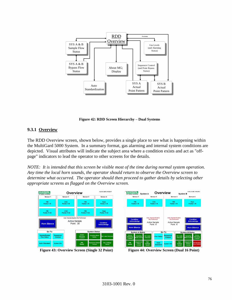
76
3103-1001 Rev. 0
Figure 42: RDD Screen Hierarchy – Dual Systems
9.3.1 Overview
The RDD Overview screen, shown below, provides a single place to see what is happening within
the MultiGard 5000 System. In a summary format, gas alarming and internal system conditions are
depicted. Visual attributes will indicate the subject area where a condition exists and act as "off-
page" indicators to lead the operator to other screens for the details.
NOTE: It is intended that this screen be visible most of the time during normal system operation.
Any time the local horn sounds, the operator should return to observe the Overview screen to
determine what occurred. The operator should then proceed to gather details by selecting other
appropriate screens as flagged on the Overview screen.
Figure 43: Overview Screen (Single 32 Point) Figure 44: Overview Screen (Dual 16 Point)
SYS A & B
B Sample Flow
Status
RDD
D
Overview
About MG; Display
Auto Standardization
Sequencer Control (and Point Bypass
Status)
)
SYS A Actual
Point Pattern
4 screens /
Gas Levels (and Alarming
Status)
)
SYS A & B
B Bypass Flow
Status
SYS B Actual
Point Pattern

77
3103-1001 Rev. 0
The RDD Overview screen consists of the following:
Due to a close similarity to the MultiGard 5000 Overview screen refer to Section 4.1.1 for a
description of any items not listed in this section.
"Sensor 1 P1-8" through "Sensor 4 P9-16" - A group of 8 HMI navigation buttons which change the
screen to view sensor data and alarming status. The bar overlaying the appropriate button(s) will
flash as an "off-page" indication whenever a condition exists that requires operator attention.
"Horn Silence" - When this RDD indicator appears the horn may be silenced by the operator by
pressing the Horn Silence button on the MultiGard 5000 System Overview display screen or by use
of an optional remote horn acknowledge switch wired in accordance with the Field Wiring Diagram.
See Chapter 5, Common Alarming for more details.
"Condition Acknowledge" - When this RDD indicator appears, any condition (trouble, warning, or
alarm) has occurred and may be acknowledged by the operator only at the MultiGard 5000
touchscreen. See Alarming, Chapter 5 for more details.
9.3.2 Gas Levels (and Alarming Status)
The Gas Levels and Alarming Status screen is identical to that described in Section 4.1.2.
.
9.3.3 Flow Status (Sample and Bypass)
The Flow Status screen is identical to that described in Section 4.1.3.
9.3.4 Auto Standardization
The Auto Standardization screen is identical to that described in Section 4.1.4 with one exception.
The ASTD trigger push buttons have been eliminated. These functions are only available at the
MultiGard 5000 touch-screen.
9.3.5 Sequencer Control (and Point Bypass Status)
The Sequencer Control and Point Bypass Status screen is identical to that described in Section 4.1.6
with two exceptions. The mode pushbutton has been replaced by a mode status indicator and the
step push button has been eliminated. The status indicator will show "Stepping Mode: Automatic"
or "Stepping Mode: Manual". Actual control of the sequencer is only available at the MultiGard
5000 touch-screen.

78
3103-1001 Rev. 0
9.3.6 Actual Point Pattern
The Actual Point Pattern screen is identical to that described in Section 4.1.7.
9.3.7 About MultiGard 5000 System
The About MultiGard 5000 System screen is identical to that described in Section 4.1.8 except for
three areas. The "DSP VER:" has been changed to "RDD VER:". All three elements associated with
password security have been eliminated.
10. Gas Concentration and Alarm Log
10.1 Introduction
The MultiGard 5000’s touchscreen interface continuously generates an electronic log of system
events that are retrievable by the user as needed. This log is stored internally to the touchscreen
interface and can be written to an SD card for viewing, printing and saving on a computer. An SD
card with a specific batch file is provided with each Multigard 5000 and should be kept in a safe
place for periodic retrieval and backup of the system event and data logs.
The events that are stored upon an occurrence basis are as follows;
Trouble conditions for any active sensor along any active sampling point on System A or B
Gas level warnings for any active sensor along any active sampling point on System A or B
Gas level alarms for any active sensor along any active sampling point on System A or B
Flow failure for any active sampling points on System A or B
Flow failure for any bypass flow points on System A or B
Horn and condition acknowledgements
Leak conditions
Alarming Enabled Status
PIR Status
Sequencer Pattern Changes
Bad Password Attempt
UCO Activity
Relay Testing Activity
Sequencer Stepping Mode Activity
Auto Standardization Activity
Calibration Gas Activity
The SD card provided with the Multigard 5000 has a 2GB capacity and so is capable of storing a
large number of event logs. The more frequently events occur in the system, the quicker the SD
capacity will be used up and old events will become unavailable. It is important to retrieve event
logs regularly and save them to a secure and backed up location.

79
3103-1001 Rev. 0
10.2 Retrieving Event Log
To Retrieve the event log from the Mutligard 5000, the SD card with the batch file needs to be
inserted into the SD slot on the back side of the touchscreen interface. With the door of the
Multigard open and looking at the back of the touchscreen interface, the SD slot is located to the left
side on the back of the interface. The SD card needs to be inserted for a moment until the LCD
screen of the interface briefly displays a white screen with a small amount of text. Once the LCD
screen returns to the Multigard 5000 program, the retrieval of the event log is complete and the SD
card can be removed from the slot.
10.3 Viewing Alarms
All necessary programs are present on the SD card to view, print and export the event log. To begin
viewing the log, insert the SD card into a Windows 7 or newer based PC. Navigate to the SD card as
shown in Figure 45.
Figure 45: SD Card Location
In the root file of the SD card, there is an executable program named FTViewFileViewer.exe.
Double click this executable file. There will be other files present in the Root. Do not modify, move
or delete these files.
Figure 46: SD Card Location
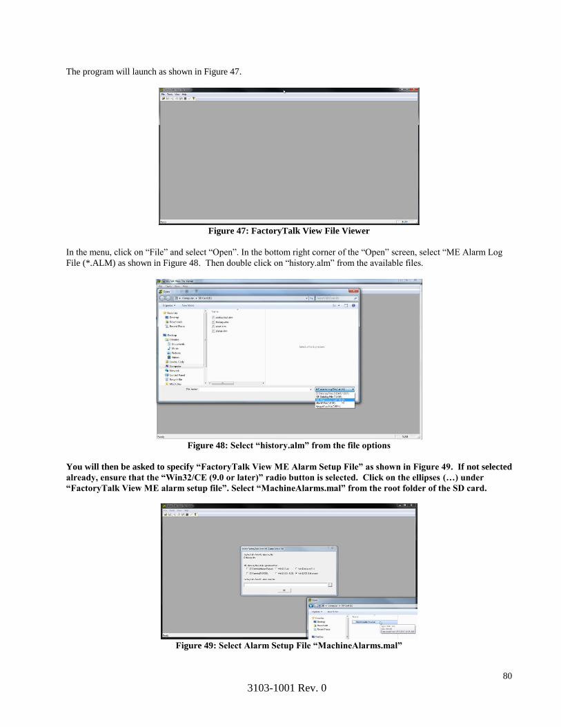
80
3103-1001 Rev. 0
The program will launch as shown in Figure 47.
Figure 47: FactoryTalk View File Viewer
In the menu, click on “File” and select “Open”. In the bottom right corner of the “Open” screen, select “ME Alarm Log
File (*.ALM) as shown in Figure 48. Then double click on “history.alm” from the available files.
Figure 48: Select “history.alm” from the file options
You will then be asked to specify “FactoryTalk View ME Alarm Setup File” as shown in Figure 49. If not selected
already, ensure that the “Win32/CE (9.0 or later)” radio button is selected. Click on the ellipses (…) under
“FactoryTalk View ME alarm setup file”. Select “MachineAlarms.mal” from the root folder of the SD card.
Figure 49: Select Alarm Setup File “MachineAlarms.mal”

81
3103-1001 Rev. 0
The event log will then load as shown in Figure 50 displaying all associated events with the Multigard 5000. The
columns of interest to a user are “Message” and “TimeOn”. These two columns indicate the event and the time it
occurred.
Figure 50: Event Log
To save the event log as a .CSV file, click on “File” in the menu and then click on “Save As”. Give the file a name and
specify the location to save. Once in this format, the file can be saved and printed as needed.
Figure 51: Save as CSV
11. Modbus TCP/BACNet IP Configuration
11.1 Introduction
The MultiGard 5000 can be equipped with an optional Ethernet gateway that allows users to access
system information and diagnostics over a Modbus TCP or BACNet IP network. The gateway is
configured with a default profile and will need to be setup specifically to a user’s network before
system and diagnostic data will become available. For a complete list of system data that is
available, refer to MSA document 3103-1047 and 3103-1048.
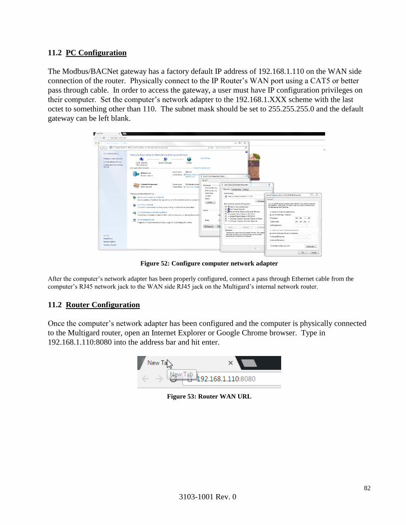
82
3103-1001 Rev. 0
11.2 PC Configuration
The Modbus/BACNet gateway has a factory default IP address of 192.168.1.110 on the WAN side
connection of the router. Physically connect to the IP Router’s WAN port using a CAT5 or better
pass through cable. In order to access the gateway, a user must have IP configuration privileges on
their computer. Set the computer’s network adapter to the 192.168.1.XXX scheme with the last
octet to something other than 110. The subnet mask should be set to 255.255.255.0 and the default
gateway can be left blank.
Figure 52: Configure computer network adapter
After the computer’s network adapter has been properly configured, connect a pass through Ethernet cable from the
computer’s RJ45 network jack to the WAN side RJ45 jack on the Multigard’s internal network router.
11.2 Router Configuration
Once the computer’s network adapter has been configured and the computer is physically connected
to the Multigard router, open an Internet Explorer or Google Chrome browser. Type in
192.168.1.110:8080 into the address bar and hit enter.
Figure 53: Router WAN URL

83
3103-1001 Rev. 0
You will immediately be prompted for a user name and password. The login credentials are as follows;
User Name: admin
Password : admin
Figure 54: Login Prompt
Once verified, the configuration utility for the router will appear as in Figure 55.
Figure 55: Main Screen

84
3103-1001 Rev. 0
To set the IP address of the Modbus/BACNet gateway as it will appear on the user’s network you
must enter the NAT settings of the router. From the main screen, hover over “Advanced” in the title
menu and click on “NAT”. The screen will appear as in Figure 43 except “10.10.79.103” will not
appear in the “LAN IP Address” column on the right and the “Enabled” checkbox will not be
checked. The user will to enter the LAN side IP address of “10.10.79.103” and check the “Enabled”
box. The user will then need to define the WAN side IP address where they would like the BACNet
IP or Modbus TCP data to be accessed once connected to their network. This address entry is
marked with a red arrow in Figure 56. Click “Save” when complete and the router will reboot after
30 seconds. Follow instructions from section 11.2 above to regain access to the router main
configuration screen once the reboot has completed.
Figure 56: NAT Screen

85
3103-1001 Rev. 0
Upon returning to the main utility screen, the WAN side IP address of the router must also be
defined by the user and follow the same scheme as the WAN side address entered in the NAT table
in the previous step. The location for the WAN side IP address is shown in Figure 57 marked with a
red arrow. The Subnet Mask and Default Gateway should be changed as needed. Once this address
has been entered, saved and router rebooted, the user will then input this address into the Internet
browser to access the router from the WAN side port. Click “Save” when complete and the router
will reboot after 30 seconds. Follow instructions from section 11.2 above to regain access to the
router main configuration screen once the reboot has completed. Use the new IP address entered in
this step as opposed to 192.168.1.110 used previously.
Figure 57: Setting WAN IP

86
3103-1001 Rev. 0
Upon returning to the main utility screen, the user has the option to change the login credentials if
desired under the “Administration” tab. The user name, password and administration port fields are
marked with a red arrow in Figure 58. Click “Save” when complete and the router will reboot after
30 seconds. The router has now been properly configured and the WAN side port can be connected
to the user’s network for use.
Figure 58: Login Credentials
87
Section 3
MULTIGARD® 5000 SYSTEM
CUSTOM FUNCTIONS AND FEATURES
Instrument Division 1-800-MSA-INST or FAX (724) 776-8783
MSA International (412) 967-3354 or FAX (412) 967-3451
In Canada 1-800-267-0672 or FAX (416) 663-5908
© Mine Safety Appliances Company 2002 – All Rights Reserved
Manufactured by
MINE SAFETY APPLIANCES COMPANY PITTSBURGH, PENNSYLVANIA 15230

88
MSA Permanent Instrument Warranty
1. Warranty – Seller warrants that this product will be free from mechanical defect or faulty
workmanship for a period of eighteen (18) months from date of shipment or one (1) year from
installation, whichever occurs first, provided it is maintained and used in accordance with Seller’s
instructions and / or recommendations. This warranty does not apply to expendable or consumable
parts whose normal life expectancy is less than one (1) year such as, but not limited to, non-
rechargeable batteries, filament units, filter, lamps, fuses etc. There is no warranty on end-user added
programming or related modifications. The Seller shall be released from all obligations under this
warranty in the event repairs or modifications are made by persons other than its own or authorized
service personnel or if the warranty claim results from physical abuse or misuse of the product. No
agent, employee or representative of the Seller has any authority to bind the Seller to any affirmation,
representation or warranty concerning the product. Seller makes no warranty concerning components or
accessories not manufactured by the Seller, but will pass on to the Purchaser all warranties of
manufacturers of such components. THIS WARRANTY IS IN LIEU OF ALL OTHER
WARRANTIES, EXPRESSED, IMPLIED OR STATUTORY, AND IS STRICTLY LIMITED
TO THE TERMS HEREOF. SELLER SPECIFICALLY DISCLAIMS ANY WARRANTY OF
MERCHANTABILITY OR OF FITNESS FOR A PARTICULAR PURPOSE.
2. Exclusive Remedy – It is expressly agreed that Purchaser’s sole and exclusive remedy for breach of
the above warranty, for any tortious conduct of Seller, or for any other cause of action, shall be the
repair and / or replacement at Seller’s option, of any equipment or parts thereof, which after
examination by Seller is proven to be defective. Replacement equipment and /or parts will be provided
at no cost to Purchaser, F.O.B. Seller’s Plant. Failure of Seller to successfully repair any
nonconforming product shall not cause the remedy established hereby to fail of its essential purpose.
3. Exclusion of Consequential Damage – Purchaser specifically understands and agrees that under no
circumstances will Seller be liable to Purchaser for economic, special, incidental or consequential
damages or losses of any kind whatsoever, including but not limited to, loss of anticipated profits and
any other loss caused by reason of nonoperation of the goods. This exclusion is applicable to claims for
breach of warranty, tortious conduct or any other cause of action against seller.

89
CUSTOM FUNCTIONS AND FEATURES
Each MultiGard 5000 System is Made-To-Order (MTO) to meet a specific application
requirement. A MultiGard 5000 System consists of the enclosure, selected configuration options,
and associated sensors/analyzers. Sensor/Analyzers can be installed internally or externally to
the MultiGard enclosure.
A MultiGard 5000 System enclosure contains several sub-systems. These sub-systems include:
Operator Interface (Display and Touch Screen Controls)
PLC processor and associated modules
User Electrical Interface:
Power Distribution and Terminal Strips
Common Alarm Relay Contacts with associated Local Alarm Buzzer
(Optional) Discrete, Programmable Alarm Relay Contacts
Sample gas flow system.
Sensor/Analyzers (Internal and/or External)
Also available for use with a MultiGard 5000 System is an optional Remote Data Display
(RDD).
A MultiGard 5000 System is configured at the factory. Refer to the System Configuration Data
Sheets in this section of the operator’s instruction manual for the factory parameters, available
operator selections, and factory imposed default values. The MultiGard 5000 System
Configuration Data Sheets are described in the Instruction Manual Section 9 in Section 2.
The MultiGard 5000 System Configuration Data Sheets include two forms of system
configuration data: Factory Configured Parameters and Default User Parameters. A system that
leaves the factory has entries placed in both sets of parameters, which makes the system
functional.
Factory configured parameters are not available to the MultiGard 5000 System
operator for data entry. Therefore, these data fields cannot be changed on-site.
User configured parameters are available to the operator and can be changed on-site.
Default entries are made at the factory and this represents the operation of the
MultiGard 5000 System upon delivery.
The MultiGard 5000 System processor retains all of the above parameters. In the event of a
processor memory fault, all factory entered default values are restored.
90
SAFETY CONSIDERATIONS
Cautions and warnings presented in the Sensor/Analyzer and the MultiGard 5000 System
sections of this instruction manual require special attention by the system operator. All cautions
and warnings must be read and understood before the MultiGard 5000 System is operated and
placed into service.
MULTIGARD 5000 FLOW SYSTEM OPERATION
In all cases, the MultiGard 5000 flow system provides sample gas or calibration gas to the
Sensor/Analyzers for analysis or calibration, respectively. Sample or calibration gas flow must
be established to the Sensor/Analyzer for normal operation.
Do not operate the system without ensuring proper flow
on all of the sample points. Flow failures will prevent
the proper analysis of gas samples and a trouble
indication will occur. Failure to restore the sample
point flow immediately may result in a hazardous
condition.
All MultiGard 5000 Systems require sample line filtration for each of the sample points.
Do not operate the system without providing adequate
sample line filtration for all sample lines. Flow system
damage will occur if dirt, water, or other foreign matter
enters the flow system.
Refer to the flow diagram for the MultiGard 5000 System or to the parts list in the MultiGard
System operator’s manual for sample line filter part numbers and descriptions.
A manual calibration of all Sensor/Analyzers is required before the MultiGard 5000 System is
placed into service. A MultiGard 5000 Manual Calibration screen is provided to aid with manual
calibration. Read the Sensor/Analyzer instruction manual in Section 3 before placing the
MultiGard system in operation.
Manual Calibration functions are described in the MultiGard 5000 Instruction Manual Section
4.1.5, Section 2. Sensor/Analyzer instructions appear in Section 3.
WARNING
NOTICE
91
Section 4
SENSOR/ANALYZER MANUALS
Supplied on SD Card
92
Section 5
MULTIGARD 5000® SYSTEM
SUPPORT DOCUMENTS

93

94
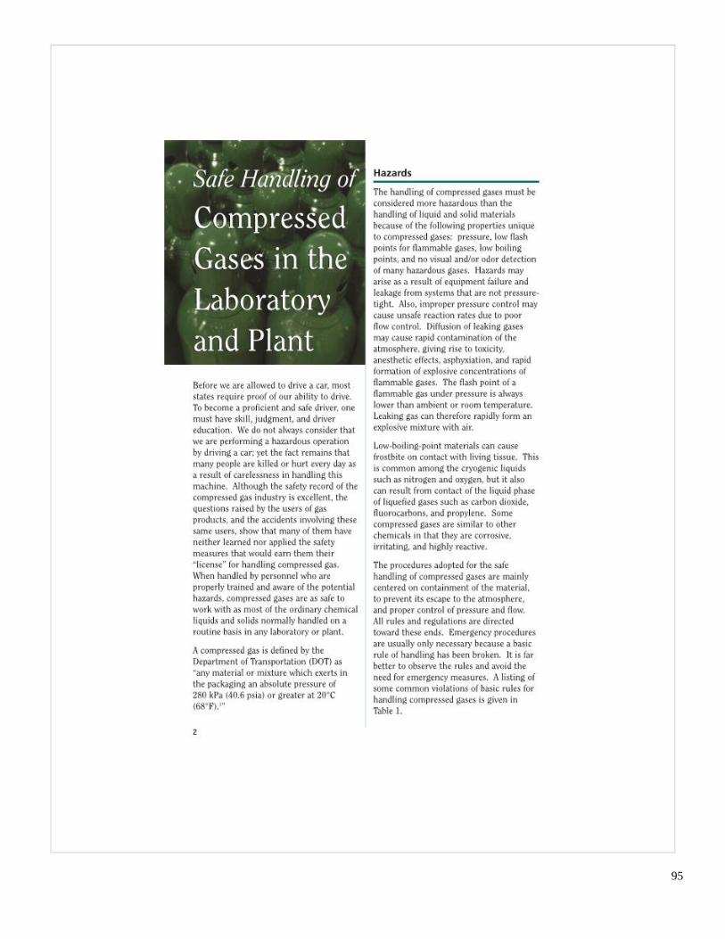
95

96

97

98
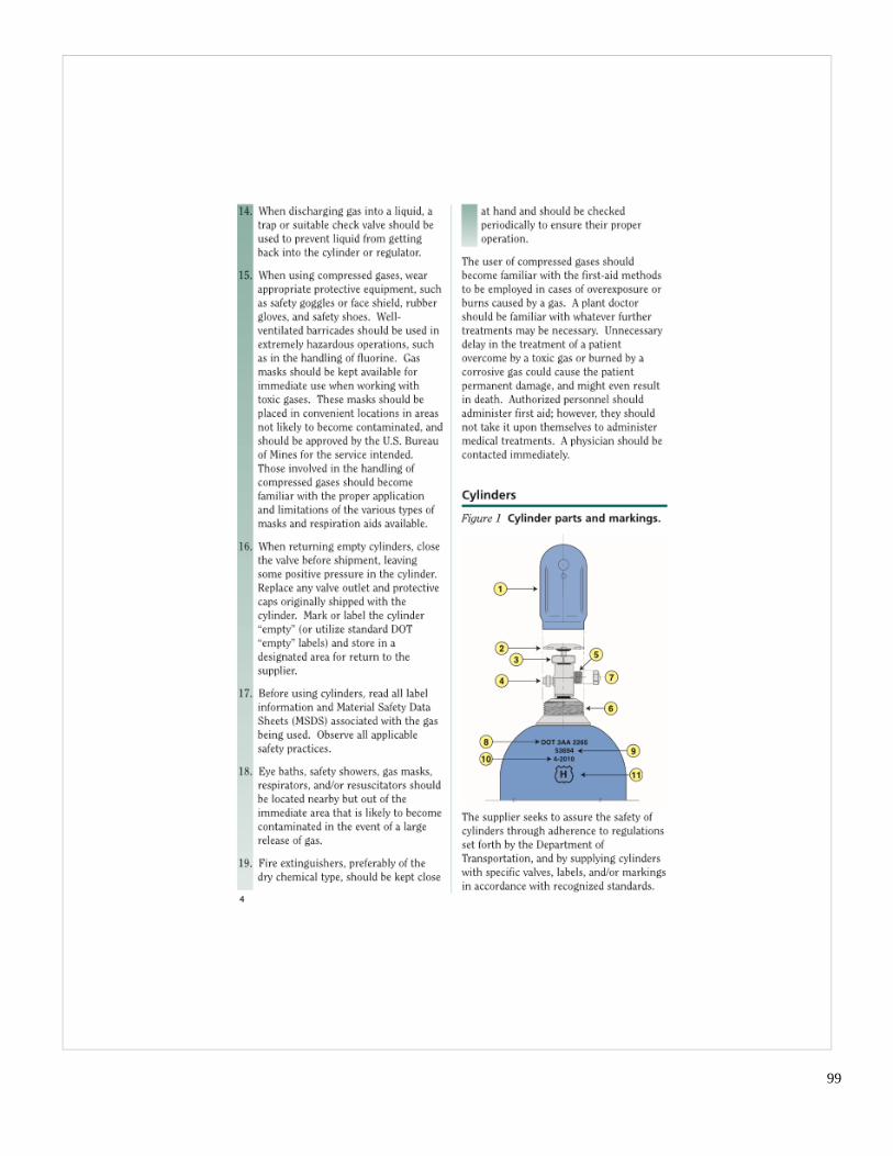
99

100
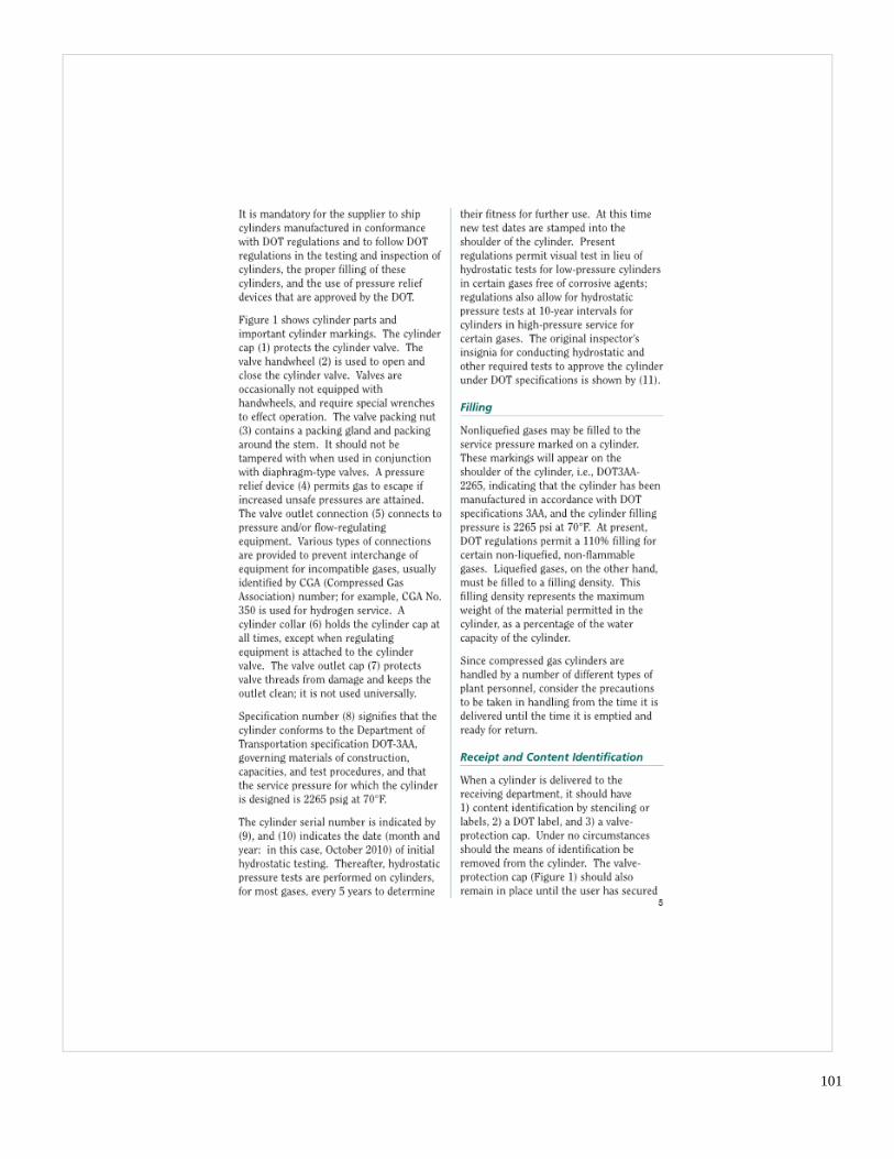
101

102
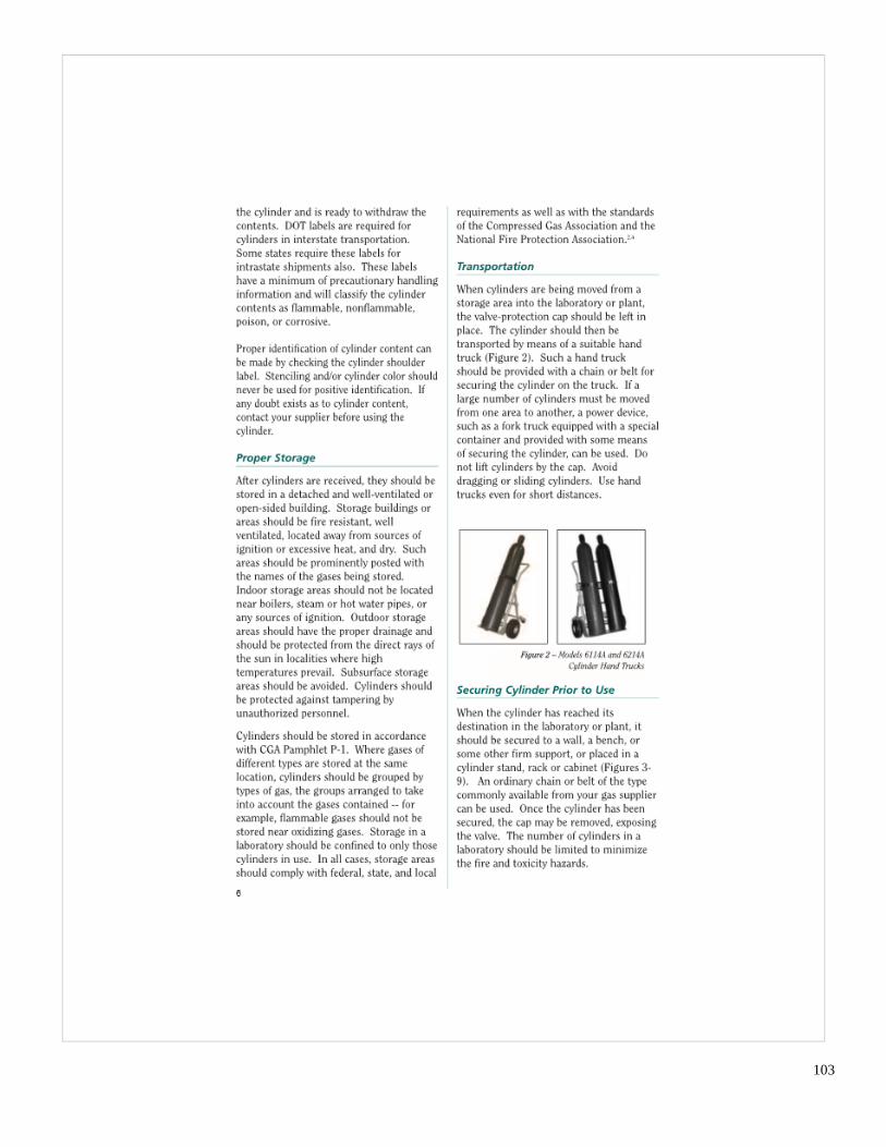
103

104
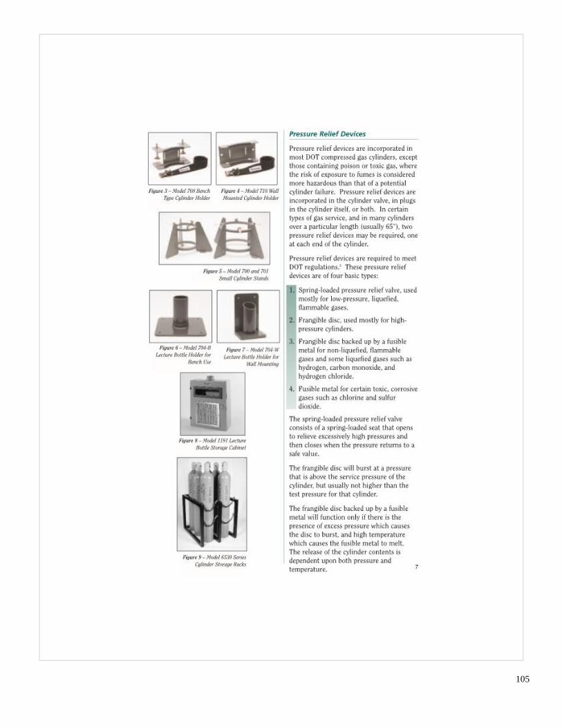
105

106

107

108

109

110
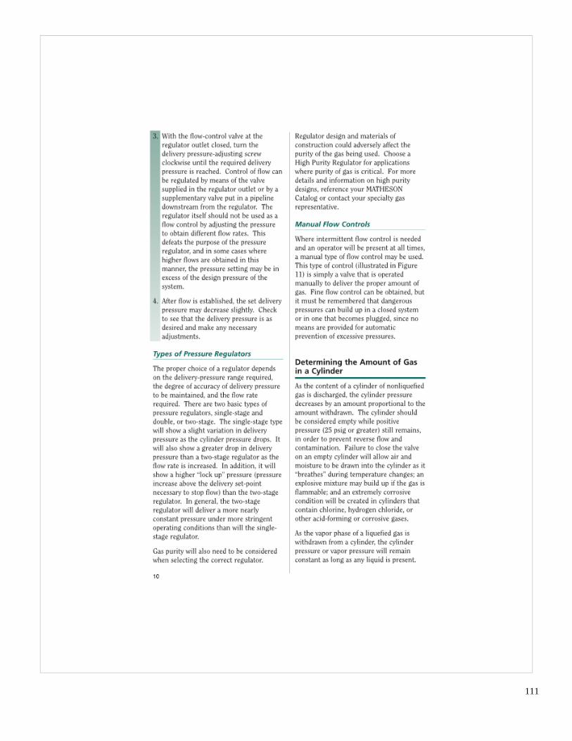
111

112
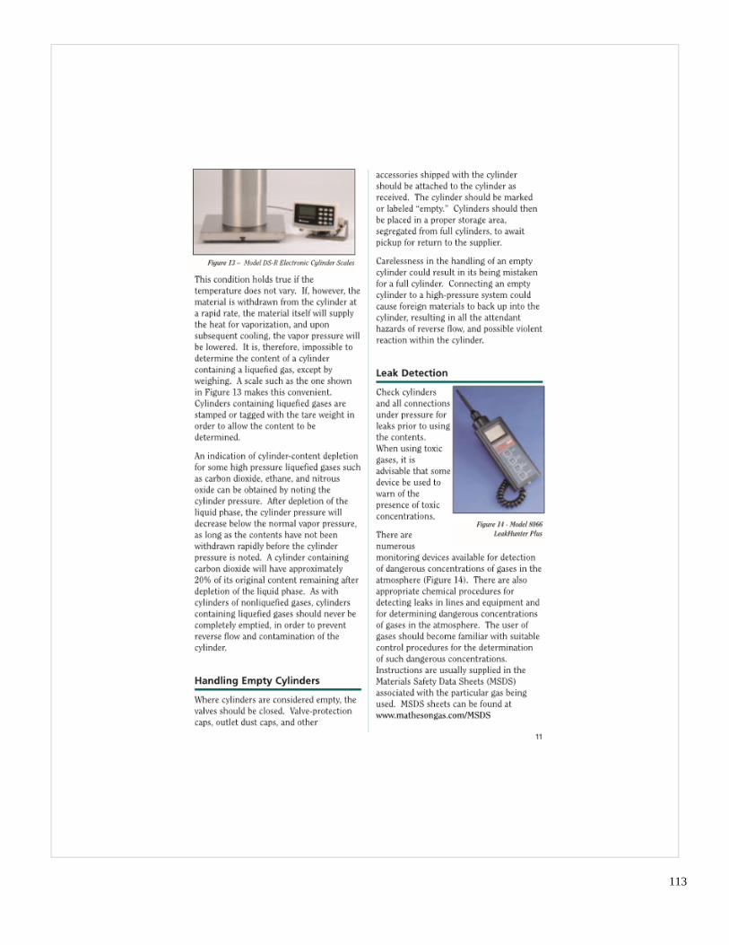
113

114

115

116

117

118
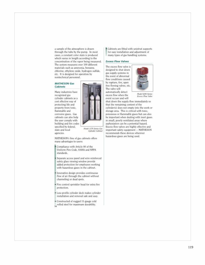
119

120

121

122

123

ASK 3103-1001 Rev. 01
REPLACEMENT PARTS AND REPAIR ORDERING INFORMATION
To expedite prompt handling of your spare parts or repair orders, please specify the following information:
ORIGINAL MSA ORDER NO.: ANALYZER AND SYSTEM SERIAL NO.: MSA PART NO.: COMPONENT DESCRIPTION: MALFUNCTION DESCRIPTION (REPAIR ORDERS ONLY):
If any of the above is not available, specify the following:
ORIGINAL MSA ORDER NO.: ANALYZER AND SYSTEM SERIAL NO.: ANALYZER TYPE AND MODEL NO.: COMPONENT MANUFACTURER: MANUFACTURER’S PART NO.: COMPONENTS DESCRIPTION: COMPONENT PARAMETERS (FLOW, PRESSURE, VOLTAGE, FREQUENCY, RPM, ETC.) MATERIALS OF CONSTRUCTION: MSA DRAWING NO. OR INSTRUCTION MANUAL PAGE NO. SHOWING
COMPONENTS: MALFUNCTION DESCRIPTION (REPAIR ORDERS ONLY): (NOTE: SEND PHOTOGRAPHS OF THE COMPONENT OR SEND THE ACTUAL COMPONENT TO
MSA IF THERE IS ANY DOUBT ABOUT ITS IDENTIFICATION)
SEND SPARE PARTS ORDERS TO:
Mine Safety Appliances Company - Instrument Division
P.O. Box 427
Pittsburgh, PA 15230
RETURN MATERIAL FOR REPAIR TO:
Mine Safety Appliances Company - Instrument Division
1000 Cranberry Woods Drive
Cranberry Township, PA 16066
RETURN GAS CYLINDERS TO:
Mine Safety Appliances Company - Instrument Division
1000 Cranberry Woods Drive
Cranberry Township, PA 16066 Attention: Cylinder Department