multifunctional self-charging structures using
TRANSCRIPT

IOP PUBLISHING SMART MATERIALS AND STRUCTURES
Smart Mater. Struct. 19 (2010) 115021 (15pp) doi:10.1088/0964-1726/19/11/115021
Multifunctional self-charging structuresusing piezoceramics and thin-film batteriesS R Anton, A Erturk and D J Inman
Center for Intelligent Material Systems and Structures, Department of MechanicalEngineering, Virginia Polytechnic Institute and State University, Blacksburg, VA 24061-0261,USA
E-mail: [email protected]
Received 26 May 2010, in final form 31 August 2010Published 30 September 2010Online at stacks.iop.org/SMS/19/115021
AbstractMultifunctional material systems combine multiple functionalities in a single device in order toincrease performance while limiting mass and volume. Conventional energy harvesting systemsare designed to be added to a host structure in order to harvest ambient energy surrounding thesystem, but often cause undesirable mass loading effects and consume valuable space. Energyharvesting systems can benefit from the introduction of multifunctionality as a means ofimproving overall system efficiency. This paper presents the investigation of a novelmultifunctional piezoelectric energy harvesting system consisting of energy generation, energystorage, and load bearing ability in a single device. The proposed self-charging structurescontain piezoelectric layers for power generation, thin-film battery layers for energy storage,and a central metallic substrate layer, arranged in a bimorph configuration. Several aspects ofthe development and evaluation of the self-charging structure concept are reviewed. Details areprovided on the fabrication of a piezoelectric self-charging structure. An electromechanicalmodel is employed to predict the response of the harvester under harmonic base excitation.Experimentation is performed to confirm the ability of the device to simultaneously harvest andstore electrical energy. Finally, both static and dynamic strength analyses are performed todetermine the load bearing ability of the structure.
(Some figures in this article are in colour only in the electronic version)
1. Introduction
With recent growth in the development of low-power electronicdevices such as microelectronics and wireless sensor nodes,the topic of energy harvesting has received much attention inthe research community. Several modes of energy harvestingexist including conversion of solar, thermal, vibration, andwind energy to electrical energy. Among these schemes,piezoelectric vibration-based harvesting has been most heavilyresearched [1, 2]. Previous studies have investigated themodeling [3, 4], circuitry [5, 6], and various applications [7–9]of vibration energy harvesting using piezoelectric devices.
Traditional piezoelectric energy harvesting systems con-sist of an active harvesting element, conditioning circuitry, anda storage medium, where the sole function of the combinedsystem is to convert ambient mechanical energy into usableelectrical energy. Furthermore, conventional systems aredesigned as add-on components to a host structure, often
causing undesirable mass loading effects and consumingvaluable space. A method of improving the functionalityof conventional harvesting designs involves the use of amultifunctional approach in which the system not only harvestsenergy, but also performs additional tasks such as storingthe scavenged energy or supporting mechanical load in thestructure. In this work, the authors investigate a novelmultifunctional approach to piezoelectric energy harvestingwith the goal of creating a device capable of harvestingvibration energy, storing the harvested energy, and supportingstructural loads.
Previous studies have investigated several different ap-proaches to developing multifunctional structures.Christodoulou and Venables [10] give a review of some ofthe earlier efforts in multifunctional structures in which detailsare given on the development of structural power materialsystems, autonomous sensing and actuating material systems,electromagnetic multifunctional material systems, and sur-
0964-1726/10/115021+15$30.00 © 2010 IOP Publishing Ltd Printed in the UK & the USA1
Smart Mater. Struct. 19 (2010) 115021 S R Anton et al
vivable, damage-tolerant material systems. Of these fourdifferent classes of multifunctional material systems, structuralpower systems are of most interest for energy harvestingapplications. Some of the original work on structural powersystems, performed by Thomas and Qidwai [11–15], involvesthe development of multifunctional structures for unmannedvehicle applications. Thomas and Qidwai [11] first introducethe concept of the multifunctional structure-battery in whichpolymer–lithium-ion battery layers with structural additives areused to both store energy and support aerodynamic loads in anunmanned aerial vehicle (UAV) system. In a subsequent study,Thomas and Qidwai [12] provide formulations for the changein flight endurance of a UAV with an integrated structure-battery, and fabricate and perform flight testing on a smallflying-wing UAV, called the WASP, which includes structure-batteries integrated into the wings. Additionally, the shearstrength of several polymer–lithium-ion batteries is obtainedexperimentally as a means of quantifying the load bearingability of the batteries.
More recently, Thomas and Qidwai have studied theuse of structure-batteries in unmanned underwater vehicles(UUVs) [13–15]. Qidwai et al [13] describe the designand fabrication of structure-batteries specifically developed formarine systems, containing lithium-ion batteries embeddedwithin fiber-reinforced polymer layers. Continuing the work,Rohatgi et al [14] present the experimental evaluation of thestructure-batteries fabricated in [13]. The multifunctionalcomposites are tested both mechanically via static three-pointbend testing, and electrically through charge/discharge cyclingof the battery layers. In their latest work, Qidwai et al [15]investigate the electrical performance of the various structure-battery designs while under load. Both static three-pointbend testing and hydrostatic loading are considered while thecharge/discharge performance of the composites is monitored.
Multifunctional solar energy harvesting systems havealso been investigated in the literature and provide a meansof combining structure and energy harvesting capabilitiesin a single device. Maung et al [16] introduce the ‘co-curing’ manufacturing process in which thin-film solar panelsare directly integrated onto carbon-fiber-reinforced epoxycomposites. Dennler et al [17] propose the concept of directlycoupling a flexible solar panel with a conventional lithium–polymer battery to create a device that can both generateand store electrical energy. Several novel types of flexiblesolar panels are developed and considered for the device,and a unique interconnection layer is proposed for electricalconnection of the solar panel and battery. Kim et al [18]expand upon the work of Dennler et al [17] and fabricate andtest a solar power laminate consisting of thin-film solar panelsand thin-film flexible lithium-based batteries connected with aflexible interconnect circuit.
Several studies have been performed in which variousaspects of multifunctional structure power systems have beeninvestigated. The next step in the development of thesesystems is to integrate structural function with energy storageand energy generation in a single multifunctional structure.Preliminary work by Dennler et al [17] and Kim et al [18] hasexamined solar energy harvesting multifunctional structureswith integrated energy storage.
Energy flow
Piezoceramic Layer
Thin-Film Battery Layer
Substrate Layer
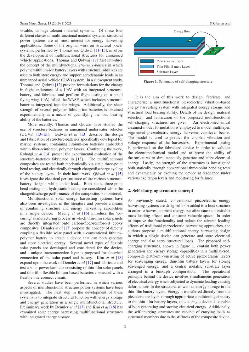
Figure 1. Schematic of self-charging structure.
It is the aim of this work to design, fabricate, andcharacterize a multifunctional piezoelectric vibration-basedenergy harvesting system with integrated energy storage andstructural load bearing ability. Details of the design, materialselection, and fabrication of the proposed multifunctionalself-charging structures are given. An electromechanicalassumed-modes formulation is employed to model multilayer,segmented piezoelectric energy harvester cantilever beams.The model is used to predict the coupled vibration andvoltage response of the harvesters. Experimental testingis performed on the fabricated device in order to validatethe electromechanical model and to prove the ability ofthe structures to simultaneously generate and store electricalenergy. Lastly, the strength of the structures is investigatedboth statically through conventional three-point bending testsand dynamically by exciting the device at resonance undervarious excitation levels and monitoring for failures.
2. Self-charging structure concept
As previously stated, conventional piezoelectric energyharvesting systems are designed to be added to a host structurein order to harvest ambient energy, but often cause undesirablemass loading effects and consume valuable space. In orderto improve the functionality and reduce the adverse loadingeffects of traditional piezoelectric harvesting approaches, theauthors propose a multifunctional energy harvesting designin which a single device can generate and store electricalenergy and also carry structural loads. The proposed self-charging structures, shown in figure 1, contain both powergeneration and energy storage capabilities in a multilayered,composite platform consisting of active piezoceramic layersfor scavenging energy, thin-film battery layers for storingscavenged energy, and a central metallic substrate layerarranged in a bimorph configuration. The operationalprinciple behind the device involves simultaneous generationof electrical energy when subjected to dynamic loading causingdeformations in the structure, as well as energy storage in thethin-film battery layers. Energy is transferred directly from thepiezoceramic layers through appropriate conditioning circuitryto the thin-film battery layers, thus a single device is capableof both generating and storing electrical energy. Additionally,the self-charging structures are capable of carrying loads asstructural members due to the stiffness of the composite device.
2

Smart Mater. Struct. 19 (2010) 115021 S R Anton et al
Figure 2. Potential use of self-charging structures: schematic ofsmall UAV with embedded self-charging structures in wing spar usedto provide local power for low-power sensor node.
The ability of the device to harvest energy, store energy, andsupport structural loads provides true multifunctionality.
The fruition of the self-charging structure concept ismainly attributed to the development of novel thin-film batterytechnology which allows for the creation of thin, lightweight,and flexible batteries. Conventional energy storage devices,such as capacitors and traditional rechargeable batteries, arelarge, bulky devices which add significantly to the overallmass and volume of the harvesting system. Additionally,traditional storage devices are not suitable for direct integrationinto the active element of an energy harvesting system as theirmass, volume, and rigidness would hinder the ability of thedevice to harvest energy. Mechanical failure is also a concernwith conventional storage elements as they may fail underthe loads applied to the harvester. Thin-film lithium-basedbatteries provide a viable solution for self-charging structures.The batteries are flexible and have a typical thickness on theorder of less than a millimeter, mass of around 0.5 g, andcapacity in the milliamp-hour range. The small capacities ofthese batteries are a good match for the low electrical outputlevels associated with piezoelectric energy harvesting, andtheir thin, lightweight platform is ideal for direct integrationinto piezoelectric harvesters to create compact, multifunctionalself-charging structures.
A novel aspect of the self-charging structure conceptis that the composite harvester can be used as a loadbearing member in a host structure. The harvester can beembedded into or used in place of an existing component,thus reducing the total mass added to the host structure.A potential application that can benefit from the energyharvesting, energy storage, and load bearing capabilities ofself-charging structures, for example, is in powering remote,low-power sensors in UAVs. Such multifunctional compositeharvesting devices can be embedded into the wing spar ofa UAV, as shown in figure 2, with the goal of providing alocal power source for remote low-power wireless sensorssuch as accelerometers, structural health monitoring nodes,or even low-power imaging devices or cameras. Providing alocal power source composed of both harvesting and storageelements is beneficial because it eliminates the need to runwires and tap into the propulsive power supply of the aircraft,thus reducing mass and complexity while allowing the sensors
(a) (b)
Figure 3. Photographs of (a) NanoEnergy® and (b) Thinergy®
thin-film batteries.
to operate wirelessly. Additionally, a multifunctional approachin which the composite harvester is embedded into the wingspar and supports structural loads in the wings is valuablebecause it can reduce or eliminate the added mass of theharvesting device.
While the wing spar example above presents one potentialuse of self-charging structures, the technology can be usedin any low-power application that can benefit from amultifunctional harvesting solution. Embedded electronicsystems and remote self-powered sensor nodes are examples ofapplications where the added mass and volume of conventionalharvesting could present design challenges, and where themultifunctional approach of self-charging structures can bebeneficial. Additionally, when coupled with an appropriatepiezoelectric device, the mechanical properties of the self-charging structure can be tailored to the meet the needsof various applications. Piezoelectric devices range fromstiff, brittle monolithic piezoceramic to flexible piezoelectricfiber-based transducers, allowing a wide range of mechanicalproperties to be obtained, thus making the self-chargingstructure a versatile energy harvesting solution.
3. Evaluation of thin-film batteries
NanoEnergy® thin-film batteries manufactured by Front EdgeTechnology, Inc. (Baldwin Park, CA) and Thinergy® thin-film batteries produced by Infinite Power Solutions, Inc.(Littleton, CO) are both investigated in this research. Bothbatteries, shown in figure 3, are flexible lithium-basedsecondary (i.e. rechargeable) cells that utilize all solid-statecomponents. Common to both types of thin-film batteries,the active elements include lithium metal anodes, lithiumcobalt dioxide (LiCoO2) cathodes, and lithium phosphorousoxynitride (LiPON) electrolyte layers. The ability to produceextremely thin (less than 200 μm) and flexible batteries canbe attributed to the use of the solid-state LiPON electrolyteas opposed to liquid or gel electrolytes found in conventionalrechargeable batteries. LiPON, developed at Oak RidgeNational Laboratory [19, 20], exhibits a high lithium-ionmobility, lending to its performance as an electrolyte, and alow electron mobility, allowing for low self-discharge rates.
3.1. Comparison to conventional rechargeable batteries
Compared to traditional rechargeable batteries, thin-filmbatteries offer a clear advantage in form factor. Table 1
3

Smart Mater. Struct. 19 (2010) 115021 S R Anton et al
Table 1. Properties of various secondary batteries.
Battery Voltage (V) Capacity (mAh) Mass (g) Volume (cm3)Specific energy(Wh kg−1)
Energy density(Wh l−1)
Energizer NH15-2450NiMH AA
1.2 2450 30.00 8.34 98.00 352.52
Energizer NH22-175NiMH 9V
8.4 175 42.00 21.52 35.00 68.31
Varta V15HNiMH button type
1.2 15 1.30 0.32 13.85 60.00
Samsung AB463446FZLi-ion cell phone
3.7 800 17.90 8.36 165.36 354.07
AA Portable Power Corp.PL-383562-C2Li–Polymer Single Cell
3.7 850 18.00 7.26 174.72 433.26
Front Edge Technology, Inc.NanoEnergy®
Lithium thin-film
4.2 4 0.45 0.11 76.36 152.73
Infinite Power Solutions, Inc.
Thinergy® MEC101-7Lithium thin-film
4.0 0.7 0.22 0.11 6.22 25.45
presents both physical and electrical properties of varioustypes of secondary batteries, in which the mass and volumeof both NanoEnergy® and Thinergy® batteries are shown tobe 1–2 orders of magnitude less than those of conventionalrechargeable batteries. Thin-film batteries are also flexible,where conventional batteries are rigid, and thin-film batterytechnology offers superior cycle life (on the order of 1000–10 000 cycles) compared to conventional rechargeable designs(typically 100–1000 cycles). The main drawback to thin-filmbattery technology lies in the low storage capacity of the cells,which in turn causes the energy density and specific energyof the batteries to suffer (see table 1). The Thinergy® cellsexhibit a much lower energy density and specific energy thanthe NanoEnergy® cells, mainly due to the increased amountof packaging material used. Although their small capacityrestricts their use to low energy applications, the flexibility,slimness, and superior cycle life of thin-film batteries allowsthem to be used in applications where previously impractical,such as direct integration into composite structures, thuscreating countless new possibilities for energy storage systems.
Another important difference between conventionalbatteries and thin-film lithium-based batteries is the internalresistance of the cells. The thin-film batteries investigatedin this study have typical internal resistances on the orderof 50–200 �. This is extremely high compared to theinternal resistances of most conventional alkaline, nickel–metal hydride, and lithium-ion secondary batteries which areon the order of 0.1–1 �. As current flows through a battery,there is a voltage drop across the internal resistance (indeedproportional to the internal resistance) of the battery, thus alarge internal resistance is detrimental to battery performance.
3.2. Battery selection
Both NanoEnergy® and Thinergy® cells are considered for usein self-charging structures. The primary difference betweenthe cells lies in the packaging material and encapsulationmethod. NanoEnergy® thin-film batteries are built by encasing
the active elements between a top and bottom mica substrateand sealing the substrate layers with a Surlyn® (DuPont,Wilmington, Delaware) sealant layer around the perimeter ofthe active elements. Electrical leads are given in the formof 100 μm thick metal foil tabs. Thinergy® batteries areassembled using a proprietary encapsulation method, however,it can be observed that they utilize a metal foil substratefor the top and bottom outer layers, which act as electrodes,and a sealant layer between the electrode layers to preventelectrical shorting. Preliminary testing of both types of thin-film batteries has revealed that the metal foil substrate of theThinergy® batteries facilitates convenient electrode applicationas opposed to the metal foil tabs of the NanoEnergy® cells,which are fragile and difficult to use. Additionally, the metalfoil substrate also appears more robust compared to the micasubstrate used on the NanoEnergy® cells, which can peel awayfrom the sealant under shear loading. Previous research hasreported similar observations in regards to the fragility of theNanoEnergy® cells [21, 22]. Although the capacity of theNanoEnergy® batteries is superior to that of the Thinergy®
cells (see table 1), Thinergy® batteries are selected for use inself-charging structures due to their increased robustness.
The Thinergy® batteries used in this study have a nominaloperating voltage of 4.0 V and a nominal capacity of 0.7 mAh.Typical dimensions are 25.40 mm×25.40 mm with a thicknessof 170 μm and a mass of about 0.450 g. Infinite PowerSolutions claims that the Thinergy® cells can exhibit 10 000cycles at 100% depth of charge before deteriorating to 80%of the initial capacity at a C/2 discharge rate. They also statethat the batteries can be charged to 90% of rated capacity in10 min and can be discharged at rates up to 40C.1 (Note thatbattery charge and discharge currents are given in terms of theirrated capacity, C. A rate of 40C for a battery with a capacity of0.7 mAh corresponds to a current of 28 mA.)
1 www.infinitepowersolutions.com.
4

Smart Mater. Struct. 19 (2010) 115021 S R Anton et al
Figure 4. Characteristic (a) charge and (b) discharge curves of the Thinergy® batteries.
3.3. Performance testing of Thinergy® batteries
Prior to combining the Thinergy® thin-film batteries withpiezoelectric devices to create self-charging structures, theperformance of the batteries is evaluated experimentally.The batteries are charged using an HP 6825A powersupply/amplifier, which provides constant-voltage charging,and discharged through standard carbon film resistors. Duringcharging and discharging, the battery voltage as well asthe current flowing in/out of the battery are monitored andrecorded using a National Instruments CompactDAQ chassisand a NI 9215 four-channel analog voltage input card. Inorder to measure the current flowing through the battery, atransimpedance operational amplifier circuit is used to convertthe current into a voltage that is measurable with the NI 9215card. The capacity achieved during charging and dischargingcan be calculated by performing numerical integration of thecurrent measurement over time as follows [21, 22]:
C =∫
i dt . (1)
Typical voltage and current measurements during chargingand discharging of the Thinergy® batteries are shown infigures 4(a) and (b), respectively. Charging is performed bysupplying 4.1 V of potential to the battery using the powersupply until only about 35 μA of current is sourced by thebattery, at which time the battery is considered fully charged.Discharging is performed by applying a resistive load of2749 � across the battery in order to draw 2C (1.4 mA)until a voltage of 3.0 V (the cutoff voltage recommendedby the manufacturer) is reached. A rate of 2C is chosenarbitrarily in order to provide a reasonable time to dischargethe battery (approximately 30 min). The batteries are capableof discharge rates up to 40C, however, such large dischargerates can degrade the performance of the batteries over time.The charge and discharge characteristics displayed are typicalfor rechargeable batteries. For this particular battery, aninitial voltage drop during discharging of 0.061 V (from4.096 to 4.035 V) and a current of 1.467 mA are observed.The corresponding internal resistance of this battery can becalculated using the relation Rint = Vdrop/I as 41.58 �, which
is slightly below the manufacturer’s specification of 50 �.Carrying out the capacity calculation given in equation (1),the capacity in charging is calculated as 0.702 mAh, andin discharging as 0.704 mA, which correlate well with themanufacturer’s specification of 0.7 mAh. It is expectedthat these capacities be reasonably close to one another,which is the case, and in both charging and discharging,the full 0.7 mAh capacity can be obtained. Overall, theThinergy® battery performs as expected, showing reasonablecharge/discharge characteristics and good charge cyclingability.
4. Fabrication details of self-charging structures
Assembly of the self-charging structures involves several stepsincluding the selection of piezoelectric and substrate materials,bonding the battery, piezoelectric, and substrate layers, andconnecting leads to the electrodes of the thin-film batteries andpiezoelectric devices. These steps are outlined in the followingsections.
4.1. Selection of piezoelectric and substrate materials
A commercially available piezoelectric material will be usedas the active energy harvesting element in this research.Several types of piezoelectric material exist, from polymerfilms with low elastic moduli and electromechanical coupling,to piezoelectric fiber-based devices with increased stiffnessand moderate coupling, to brittle monolithic ceramics withhigh electromechanical coupling. As a compromise betweenthe high energy generation of monolithic ceramics and thestrength and flexibility of fiber-based devices, QuickPack®
piezoelectric devices (Mide Technology Corp., Medford, MA)are selected for use in self-charging structures. QuickPack®
devices contain monolithic piezoceramic (PZT-5A) activeelements bracketed by kapton layers to protect the activeelement and provide additional robustness.
Several substrate materials can be considered for use inself-charging structures. Typical piezoelectric bimorph energyharvesters contain a thin, relatively flexible substrate, such asbrass or aluminum, such that the stiffness of the substrate does
5

Smart Mater. Struct. 19 (2010) 115021 S R Anton et al
Figure 5. (a) Components used in self-charging structure; (b) vacuum bagging setup; (c) complete self-charging structure.
Table 2. Physical parameters of self-charging structure components.
ParameterAluminumsubstrate
QP10Ndevice
QP10N activeelement
Thinergy®
batteries
Thickness (mm) 0.127 0.381 0.254 0.178Width (mm) 25.400 25.400 20.574 25.400Length (mm) 63.500 50.800 45.974 25.400Mass (g) 0.530 2.250 0.460
not dominate the overall structural stiffness in order to allowadequate vibration energy to be induced in the piezoelectricelements. The substrate layer material selected in this studyfor use in the self-charging structures is 1100-O aluminumalloy. Alternative substrates can be used, however, to alter thecharacteristics of the self-charging structures to fit the designparameters of a given application.
Important physical parameters of the various componentsused to construct the prototype self-charging structure, shownin figure 5(a), are given in table 2. As stated previously,the QuickPack® devices consist of a central monolithicpiezoceramic (PZT-5A) layer bracketed by 0.0635 mm thickkapton layers that include embedded electrodes. Dimensionsof both the overall device and the active element are given inthe table.
4.2. Vacuum bonding and electrode attachment
Fabrication of the self-charging structures is performed byseparately bonding each layer using a vacuum baggingprocedure, shown in figure 5(b), to achieve thin, uniformbonding layers. 3M ScotchWeld™ DP460 two-part epoxy ischosen for the bonding layer due to its high shear strength(27.58 MPa when bonded to aluminum) and high volumeresistivity (2.4 × 10¹⁴ ohm cm). Bonding is achieved byapplying a thin layer of epoxy between two component layers,placing the device in vacuum, and allowing it to cure for 6 h.The thin-film batteries are selected as the outermost layersto facilitate attachment of electrical leads. They are placedtowards the free end of the device to reduce the induced strainin the batteries in order to help prevent electrical or mechanicalfailure.
With all of the self-charging structure layers bonded, thefinal step in fabrication involves attaching electrical leads toboth the piezoceramic and battery layers. 22-gauge insulatedand stranded wire is soldered to both the QuickPack® layersand battery layers to provide electrical connections. Careis taken when soldering leads to the Thinergy® batteries toprevent shorting as connection to the bottom electrode is givenvia a thin overlapping strip accessible from the top surface.Additionally, an epoxy coating is placed over the electricalconnections on the battery to provide electrical isolation andincreased mechanical strength. A photograph of a completeself-charging structure with electrical leads can be seen infigure 5(c).
5. Electromechanical modeling
The most common form of a vibration-based energy harvestingdevice is the cantilever beam attached to a vibrating hoststructure and subject to base excitation. In this work,the self-charging structures are modeled and tested in thecantilever configuration to evaluate their energy harvestingcapability. Distributed-parameter analytical solutions forcantilevered unimorph [3], bimorph [23], and multi-morph [24] energy harvester beams have been presented inthe recent literature. Convergence of the electromechanicalRayleigh–Ritz formulation [25, 4] to the analytical solution [3]for sufficient number of kinematically admissible functionshas been reported in the literature [4]. Assumed-modesformulation [26] is an alternative way of describing thespatially discretized system dynamics and the resultingequations are identical to those of the Rayleigh–Ritz method.Both of these techniques are preferred especially for structureswith varying geometric or material properties such as multi-segment structures. The two-segment self-charging structuresdeveloped in this work are modeled using the assumed-modestechnique. The following is a summary of the derivation.
The cantilevered self-charging structure shown in figure 6consists of two uniform regions in the longitudinal direction(x-direction). The region 0 � x � L1 has piezoceramic,substructure, kapton as well as high shear strength epoxylayers used for bonding while the region L1 � x � L hastwo thin-film battery layers and two more epoxy layers in
6

Smart Mater. Struct. 19 (2010) 115021 S R Anton et al
Figure 6. (a) Schematic of self-charging structure with piezoceramic, battery, substrate, kapton, and epoxy layers; (b) cross-sectional views ofthe two regions.
addition to the layers of the former region. The structure isexcited under translational base acceleration imposed in thetransverse direction (z-direction) at the clamped end. Thecantilevered structure is assumed to be sufficiently thin so thatthe shear deformation and rotary inertia effects are negligiblefor the practical modes of interest (the fundamental mode is ofparticular interest in energy harvesting), hence the derivationis based on the Euler–Bernoulli beam assumptions. The readeris referred to [26] for Rayleigh and Timoshenko type energyharvester models to describe the dynamics of moderately thickenergy harvester beams. The electrode pairs (of negligiblethickness) covering the opposite faces of each piezoceramiclayer are assumed to be perfectly conductive so that a singleelectric potential difference can be defined across them.
The extended Hamilton’s principle with internal electricalenergy is [26]
∫ t2
t1
(δT − δU + δWie + δWnc) dt = 0 (2)
where δT , δU , and δWie are the first variations of the totalkinetic energy (T ), the total potential energy (U ) and theinternal electrical energy (Wie), and δWnc is the virtual workof the non-conservative mechanical force and electric chargecomponents. The effect of base excitation is considered in thetotal kinetic energy term and proportional mechanical dampingeffect is to be introduced in the spatially discretized form,therefore the only non-conservative virtual work is due to theelectric charge output (Q):
δWnc = δWnce = Qδv (3)
where v is the voltage across the external load.The vibration response of the beam relative to its moving
base is
w(x, t) =N∑
i=1
φi(x)ηi(t) = ΦT(x)η(t) (4)
where Φ(x) is the vector of admissible functions, η(t) is thevector of generalized modal mechanical coordinates, N is thetotal number of mechanical modes used in the expansion andthe superscript T stands for transpose. A simple admissiblefunction that satisfies the essential boundary conditions of aclamped-free thin beam is [27, 4]
φi (x) = 1 − cos
((2i − 1)πx
2L
)(5)
where i is the modal index.The electromechanical Lagrange equations are given for
the generalized coordinates ηi and v as [26]
d
dt
(∂T
∂ηi
)− ∂T
∂ηi+ ∂U
∂ηi− ∂Wie
∂ηi= 0 (6)
d
dt
(∂T
∂v
)− ∂T
∂v+ ∂U
∂v− ∂Wie
∂v= Q (7)
which yield the governing equations
Mη(t) + Cη(t) + Kη(t) − Θv(t) = −FaB(t) (8)
Ceqp v(t) + v(t)
Rl+ ΘT η(t) = 0 (9)
where M, C, and K are the mass, damping, and stiffnessmatrices, F is the effective forcing vector, Θ is theelectromechanical coupling vector, Ceq
p is the equivalentcapacitance, Rl is the external load resistance and an over-dotrepresents differentiation with respect to time. In equations (8)and (9), proportional damping is assumed so that standardmodal analysis can be used with mathematical convenience(i.e. the damping matrix has the form C = αM + βK where α
and β are constants of proportionality).If the base acceleration is assumed to be harmonic of the
form aB(t) = aBejωt (where ω is the excitation frequencyand j is the unit imaginary number), the steady-state voltage
7

Smart Mater. Struct. 19 (2010) 115021 S R Anton et al
Figure 7. (a) Self-charging structure mounted to shaker and (b) overall experimental setup for vibration testing.
response and vibration response can be obtained as
v(t) = jω
(1
Rl+ jωCp
)−1
ΘT
(K − ω2M + jωC
+ jω
(1
Rl+ jωCp
)−1
ΘΘT
)−1
FaBejωt (10)
w(x, t) = −ΦT (x)
(K − ω2M + jωC
+ jω
(1
Rl+ jωCp
)−1
ΘΘT
)−1
FaBejωt . (11)
The voltage output-to-base acceleration and the vibrationresponse-to-base acceleration frequency response functions(FRFs) can be extracted as v(t)/aBejωt and w(x, t)/aBejωt ,respectively. Note that, in this approximate analytical solutiontechnique, sufficient number of admissible functions should beused for convergence of the natural frequencies of interest tothe exact values [4, 26].
6. Experimental validation of self-charging structureconcept
Experiments are performed on the fabricated self-chargingstructure shown in figure 5(c) in order to confirm the abilityof the device to simultaneously harvest and store electricalenergy. The performance of the self-charging structure isevaluated by mounting the device in a cantilever fashion andsubjecting it to base excitations while monitoring the energytransfer between the piezoceramic layers and the battery layers.The following sections describe the results of the experimentalcharacterization.
6.1. Frequency response measurements
The self-charging structure is clamped to a small TMCSolution Dynamic TJ-2 electromagnetic shaker with anoverhang length of 43.7 mm, as shown in figure 7(a). Inorder to determine the resonant frequency and optimal loadresistance of the clamped device, experiments are conductedto obtain the electromechanical FRFs of the self-chargingstructure for a set of resistive electrical loads (ranging from100 � to 1 M�). SigLab data acquisition hardware is usedfor all FRF measurements. The input acceleration is measuredusing a PCB U352C67 accelerometer, the tip velocity is
measured using a Polytec OFV303 laser Doppler vibrometer,and the voltage output of the self-charging structure ismeasured directly with the SigLab data acquisition system.The overall test setup is shown in figure 7(b).
For the series connection of the piezoceramic layers(to obtain larger voltage output), the voltage output-to-baseacceleration and tip velocity response-to-base accelerationFRFs of the self-charging structure are shown in figures 8(a)and (b), respectively (where the base acceleration is givenin terms of the gravitational acceleration, g = 9.81 m s−2).To verify the electromechanical model developed for theprediction of the output of the harvester, the voltage output andthe vibration response FRFs are predicted using equations (10)and (11), respectively, and plotted over the experimentalresults in figure 8. Twenty modes are used in the assumed-modes formulation (N = 20) to ensure the convergenceof the fundamental natural frequency using the admissiblefunctions given by equation (5). As the load resistance isincreased from 100 � to 1 M�, the experimental value of thefundamental resonance frequency moves from 204.0 Hz (closeto short-circuit conditions) to 211.1 Hz (close to open-circuitconditions). These two frequencies are the short-circuit andthe open-circuit resonance frequencies and they are predictedby the electromechanical model as 204.1 Hz and 211.0 Hz,respectively. The amplitude-wise model predictions are alsoin agreement with the experimental measurements. It isworth mentioning that the maximum voltage output is obtainedfor the largest load resistance for excitation at the open-circuit resonance frequency as 34 V g−1 (peak amplitude).The optimal electrical loads for excitations at 204.0 Hz and211.1 Hz are identified as 9.8 k� and 91.0 k� (among theresistors used), respectively, which yield similar experimentalpeak power outputs of 2.8 mW g−2 and 3.1 mW g−2,respectively. These voltage and power output values given interms of base acceleration are, however, frequency response-based linear estimates obtained from low-amplitude chirpexcitation and they are not necessarily accurate for large-amplitude excitations with nonlinear response characteristics.
After the preliminary analysis for the resistive load case,the piezoceramic and thin-film battery layers are connected tothe input and output of a simple linear voltage regulator circuit(consisting of a full bridge rectifier, smoothing capacitor,and voltage regulator), respectively. The electrical boundaryconditions of the piezoceramic layers then become more
8

Smart Mater. Struct. 19 (2010) 115021 S R Anton et al
Figure 8. The (a) voltage-to-base acceleration and (b) tip velocity-to-base acceleration FRFs of the self-charging structure for a set of resistiveloads.
Figure 9. Experimental curves for self-charging structures in (a) charging and (b) discharging under ±1.0 g acceleration at 210.0 Hz.
sophisticated. The tip velocity FRF is measured for thiscase, and is plotted in figure 8(b). It appears from the figurethat the case with the largest resistive load (1 M�, close toopen-circuit conditions) successfully represents the vibrationresponse of the self-charging structure when connected to thecircuit, which exhibits resonance around 210.0 Hz.
6.2. Electrical charge/discharge measurements
With the resonant frequency of the self-charging structureconnected to the circuit obtained, the energy harvestingperformance of the device can be experimentally evaluated.Using the same experimental setup shown in figure 7, the self-charging structure is excited at resonance (210.0 Hz) with thepiezoelectric layers configured to charge the thin-film batterylayers through the linear voltage regulator circuit. For thisexperimentation, the two piezoelectric layers are connected inseries for increased voltage output and used to charge a singlebattery layer. The input base acceleration amplitude is set to±1.0 g. The device is excited for 1 h and the battery voltageand current into the battery are measured throughout the test.Once the test is complete, the battery is discharged using a2749 � resistor in order to draw 2C of current out of thebattery. Results from both the charging and discharging tests
are shown in figure 9. From figure 9(a), it can be seen thatthe piezoelectric layers are able to supply an average of about0.08 mA of current into the battery. Using equation (1), thecapacity during charging is found to be 0.0781 mAh. Duringdischarging, the current output is held at 1.4 mA for about 120 sbefore beginning to decay and a capacity of 0.0663 mAh isfound by integrating the current over time. There is a slightdifference between the capacities calculated in charging anddischarging, which is likely a leakage effect where some of theenergy during charging is dissipated in the battery, thus thereis a small decrease in capacity when discharging.
The charge/discharge results presented in figure 9 provethe ability of the self-charging structures to simultaneouslygenerate and store electrical energy in a multifunctional man-ner, and validate the concept of self-charging. Furthermore,the current of 0.08 mA corresponds to an average power ofaround 0.306 mW during charging. This is a reasonable valuefor piezoelectric energy harvesting, where typical harvestedpowers are in the microwatt to milliwatt range [1].
7. Strength analysis
It has been proposed that the self-charging structures developedin this work be directly integrated into host structures in
9

Smart Mater. Struct. 19 (2010) 115021 S R Anton et al
Figure 10. Schematic of three-point bending test fixture.
a multifunctional manner. Inherent in this proposal is thefact that the self-charging structures must act as load bearingmembers. Both static and dynamic testing is carried out inorder to determine the strength of the self-charging structures.Results of the strength testing can be used as a designtool in the development of embedded self-charging structuresystems. The following sections outline the formulations andprocedures used to define the failure strength of the self-charging structures, as well as the results of experimentalfailure testing.
7.1. Static failure analysis and testing
Bending tests (or flexure tests) are usually employed toevaluate tensile strengths of brittle materials [28] (such as thepiezoceramic layers in the case of self-charging structures).Classical three-point bending tests are performed in this studyin order to experimentally evaluate the strength of the variouscomponents of the self-charging structures as well as thecomplete assembly. A schematic of a three-point bending testsetup is shown in figure 10. The transverse load, P , is appliedat the center (x = L/2) of the uniform rectangular beamwith support span L, therefore, the maximum bending momentoccurs at this point (Mmax = P L/4). The static load, Pf,required for transition from elastic material behavior to eitherplastic behavior (for ductile materials) or abrupt failure (forbrittle materials) is considered in this work as the mechanicalfailure load that leads to the mechanical failure strength. Themaximum bending moment that corresponds to the failure load(Pf) of the assembly is defined as the failure bending moment(Mf).
The bending strength of a simple beam placed under three-point bending is defined from Euler–Bernoulli beam theory as
σb = 3L
2bh2Pf (12)
where b is the sample width, and h is the sample thickness.The maximum bending stress of a given layer of a
multilayer composite device, such as the complete self-charging structure assembly, can be defined as
σ maxb = Ykhkn
Y IMf = Ykhkn L
4Y IPf (13)
where σ maxb is the maximum stress of a layer at a given failure
load of the device, Yk is the elastic modulus of the layer ofinterest (layer k), hkn is the distance from the neutral axis to
the outer surface of the kth layer, and Y I is the overall bendingstiffness of the multilayer beam. In order to obtain the valueof Y I of a multilayer beam, a cross-section transformation (asdescribed by Erturk and Inman [3]) can be used. In addition,a beam-like aspect ratio is assumed in the foregoing derivationand thin-plate parameters can be used for bending of plate-likeconfigurations [26].
Equation (12) gives the failure strengths of the individuallayers under separate loading, whereas equation (13) can beused to estimate the maximum stresses of the individual layersfor the failure load of the assembly. It is worth mentioningthat the maximum stress of a layer for the failure load of theassembly might be lower than its individual failure strength.For instance, for the failure load that results in fracture of apiezoceramic layer in a multilayer assembly, the maximumstress in the metallic layer could be lower than its individualfailure strength. Nevertheless, the overall structure is assumedto be failed when any layer starts exhibiting brittle or ductilefailure behavior.
Experimental testing is performed using an Instron 4204universal test frame equipped with a 1000 N load cell and asmall three-point bend fixture with adjustable supports, shownin figure 11(a). Each specimen rests on the two lower supportpins, which are spaced 20 mm apart, and the central pinis lowered using the machine at a rate of 0.3 mm min−1
until a prescribed displacement is reached. In each case, thespecimens fail before the maximum displacement is achieved.
Three individual samples are tested for the aluminumsubstrate, QP10N piezoceramic, and Thinergy® battery layers.Conventionally, three-point bend testing is performed on beam-shaped samples in order to eliminate Poisson effects. It isdesirable, however, to test the Thinergy® battery samplesin an unmodified state as dicing the batteries could resultin damage to the packaging and delamination, therefore,plate-like samples are tested in this work. Additionally, theQuickPack® samples are not uniform across their cross-sectiondue to the embedded electrodes in the kapton layers, thuscutting beam-shaped samples out of the device would givesamples of varying composition. The Thinergy® samples aretested without modification, the aluminum specimens are cut to25.4 mm × 25.4 mm, and the QuickPack® samples are cut inhalf (resulting in two identical samples of about 25.4 mm ×25.4 mm) to fit in the test fixture. A single self-chargingstructure is tested and cut in half such that each section canbe tested separately. Photographs of the two self-chargingsections after failure testing are shown in figures 11(b) and (c).The load and crosshead displacement are recorded throughouteach test, and typical load–deflection curves for the individuallayers as well as the complete structure are shown in figure 12.From the results presented in figure 12(a), it is clear thatthe individual QuickPack® piezoceramic layers exhibit brittlefailure and the individual aluminum substrate and Thinergy®
battery layers exhibit ductile failure. In the case of thealuminum sample, the failure load is taken where a slight,prolonged drop in the force is observed, as noted in the figure.From figure 12(b), it can be seen that the root section ofthe self-charging structure experiences brittle failure, wherethe tip section exhibits simultaneous ductile and brittle failure
10

Smart Mater. Struct. 19 (2010) 115021 S R Anton et al
Figure 11. (a) Three-point bend fixture; self-charging structures after failure (b) root section, (c) tip section.
Root
Tip
Simulataneous Ductile/Brittle FailureBrittle Failure
Quick Pack
Thinergy
Ductile Failure
Aluminum
(a) (b)
Figure 12. Load–deflection curves for (a) individual layers and (b) complete self-charging structure sections.
Table 3. Failure loads for three-point bending tests.
ParameterAluminumsubstrate
QP10Ndevice
Thinergy®
batteries
Failure load (N) 3.21 7.25 6.583.36 8.80 5.473.66 8.50 5.89
Minimum (N) 3.21 7.25 5.47
Complete self-charging structure
Root section Tip section
Failure load (N) 39.9 165.3
behavior. This phenomenon is likely due to failure occurring inthe piezoceramic (brittle) and battery (ductile) layers for nearlythe same applied load. The failure load results for all of thespecimens tested are presented in table 3.
With the failure loads obtained, equations (12) and (13)can be used to obtain the maximum bending stress values foreach sample tested. The minimum failure load value is used inthe calculations for the individual layers to give a conservativeestimate. For the complete self-charging structure, the overallbending stiffness (Y I ) of the root section (containing only thealuminum substrate and piezoceramic layers) is calculated asY I = 0.0652 N m2, and of the tip section (containing the
Table 4. Maximum stress at failure for three-point bending tests.
ParameterAluminumsubstrate
QP10NDevice
Thinergy®
batteries
Individual layers
Failure stress (MPa) 229.27 159.82 199.33
Self-charging structure—root
Failure stress (MPa) 14.62 99.57 N/A
Self-charging structure—tip
Failure stress (MPa) 20.15 137.23 155.44
aluminum substrate, piezoceramic layers, and battery layers)is calculated as Y I = 0.1960 N m2. It should be noted that thecalculation of failure stress in the QuickPack® piezoceramiclayers considers the dimensions of only the active element,ignoring the kapton, as the ceramic experiences brittle failure.The calculated failure strength values for each of the specimensare given in table 4.
From the results, it can be seen that failure in the rootsection of the self-charging structure is due to failure of thepiezoceramic layers. At the point of failure, the maximumstress in the aluminum layer is much less than the failurestress observed in a single aluminum layer. The maximum
11

Smart Mater. Struct. 19 (2010) 115021 S R Anton et al
stress in the QuickPack® is about half of the failure stressobtained for a single layer, however, it is on the same order ofmagnitude. Although there is a significant difference betweenthe maximum stress of the single layer and composite device,it is typical in brittle failure to observe a wide range of failureloads (thus failure stresses) for a single material. Results for thetip section of the self-charging structure show failure in boththe piezoceramic and battery layers with stresses similar to thefailure stress of the individual layers in both cases. This resultis confirmed by the simultaneous brittle and ductile failureobserved in figure 12(b). Overall, it can be concluded that thepiezoceramic and battery layers are the critical layers in three-point bending failure.
7.2. Dynamic failure analysis and testing
A series of dynamic strength tests are conducted to gain anunderstanding of the dynamic loading that can be withstoodby the self-charging structures without failure. Usingequations (10) and (11), the maximum dynamic stress of thekth layer of a thin self-charging structure under base excitationcan be expressed as [24]
σf
k (xcr, t) = −Ykhkn∂2w(x, t)
∂x2
∣∣∣∣x=xcr
+ λk(e31)kvk(t)
h pk(14)
where xcr is the critical position on the beam where thecurvature is maximum (e.g. it is the root for the fundamentalmode of a uniform cantilever), the elastic modulus, Yk , isthe constant electric field modulus for a piezoceramic layer,and (e31)k , vk(t), and h pk are the effective piezoelectricconstant, voltage output, and thickness of the kth layer if itis a piezoceramic layer. Furthermore λk = 1 if the kthlayer is a piezoceramic layer, otherwise it is zero. Fromequations (10), (11), and (14), the maximum dynamic stressFRF of the kth layer per base acceleration can be obtained asσ
fk (xcr, t)/aBejωt . For a given value of base acceleration, the
maximum dynamic stress values of the individual layers can beextracted. It is expected that the thin-film batteries may exhibitelectrical failure due to harmonic excitation, therefore, themaximum dynamic stress in the battery layer that correspondsto this prescribed electrical failure condition can be called theelectrical failure strength of the battery under dynamic loading.
Estimates of the maximum stress-to-base accelerationFRFs of the aluminum, piezoceramic, and battery layers aregiven in figure 13. The average epoxy thickness between thepiezoceramic and aluminum layer is measured as 0.0173 mmwhereas the average epoxy layer thickness between the outerkapton and the battery layers is negligible. The distances (hkn )from the neutral axis of the symmetric structure to the outersurfaces of the aluminum, piezoceramic, and battery layersare then estimated as 0.0635 mm, 0.398 mm, and 0.614 mm,respectively. The elastic moduli (Yk ) of these structures aretaken as 70 GPa, 69 GPa, and 55 GPa, respectively. Since thealuminum and piezoceramic layers are clamped at the root, themaximum stresses for these layers are expected to be at the root(i.e. xcr = 0 in equation (14)), however, since the 25.4 mm longbattery layers are located close to the free end of the structure,the maximum stress in the battery layers is expected to be at
Figure 13. Estimates of the maximum dynamic bending stress in thepiezoceramic, battery, and aluminum layers.
the edge of the battery closest to the clamp (which correspondsto xcr = 18.3 mm when the device is clamped in the fixture).From the results presented in figure 13, the maximum bendingstress per base acceleration of the aluminum, piezoceramic,and battery layers are 5.7 MPa g−1, 20.5 MPa g−1, and3.1 MPa g−1, respectively. These linear estimates of thestress per base acceleration provide insight into the amountof base acceleration that can be safely imposed on the device.For large-amplitude excitations, however, both geometric andmaterial nonlinearities may exist in the cantilever piezoelectricstructure, thus the linear estimates must be used with care.
Dynamic failure testing is conducted using the sameexperimental setup shown in figure 7 by subjecting thecantilevered harvester to resonant base excitations (previouslyfound to be 210.0 Hz) of increasing amplitude until failureis observed in either the battery layers (electrical failure) orpiezoceramic layers (mechanical failure). Electrical failure isdefined as a 10% decrease in either the charge or dischargebehavior of the battery layers as compared to baselinecharge/discharge curves, where mechanical failure is defined asa 10% decrease in the power output of the piezoceramic layers.The self-charging structure is again clamped to the shakerwith an overhang length of 43.7 mm and remains undisturbedthroughout the duration of the dynamic testing.
An initial baseline charge/discharge measurement isobtained for the device using the power supply (the sameprocedure used previously to evaluate the performance ofthe self-charging structures) and all future measurements forbattery failure are compared to this baseline. Once the baselineis obtained, the device is first excited at resonance at aninitial acceleration input level of ±0.2 g for 1 h. During thetest, the piezoceramic layers are connected in series to thesimple linear regulator harvesting circuit and used to chargea single thin-film battery (which is initially fully dischargedto 3.0 V). The battery voltage and current are monitored andrecorded in order to evaluate the health of the piezoelectriclayers. After 1 h, the excitation is ceased and a dischargetest (drawing 2C through a 2749 � resistor) is performed onthe battery. The self-charging structure is then allowed to sitfor 24 h before testing is resumed, as chemical failure in thebattery (perhaps due to delaminations) may take time to take
12

Smart Mater. Struct. 19 (2010) 115021 S R Anton et al
Figure 14. Charge/discharge capacities measured for (a) power supply and (b) piezoceramic charging.
effect. After 24 h, the thin-film battery is charged using thepower supply and then discharged. This data is compared tothe baseline charge/discharge curves, and significant changesindicate electrical battery failure (caused by the excitation theprevious day). Finally, the acceleration amplitude is increasedand the process is repeated. It is expected that for largerexcitation amplitudes, the piezoelectric layers will providemore power. Deviations in this trend indicate mechanicalfailure in the piezoelectric layers. Complete results from thedynamic failure testing for the power supply charge/dischargeare given in figure 14(a) for base acceleration values from0.2 g to 7.0 g. Additionally, the charge/discharge resultswith the piezoceramic layers charging the battery are givenin figure 14(b). Based on the maximum stress predictionsgiven in figure 13, an upper limit of 7.0 g (corresponding to145 MPa of stress in the piezoceramic layer) is chosen. Recallthe piezoelectric layer exhibited a maximum stress between100 and 140 MPa in static failure. Although linear estimatesare used here, they provide a reasonable basis for limiting thedynamic excitation level.
From the dynamic failure testing results presented infigure 14(a), it can be seen that as the excitation amplitude isincreased from 0.2 g to 7.0 g, there is no significant changein the power supply charge or discharge behavior. In eachcase, the charge amplitude is slightly higher than the dischargeamplitude, likely due to leakage in the battery. The powersupply charge after 5.5 g excitation is abnormally high, thus thebattery initially appears damaged, but continuation of testingat higher excitation levels shows that the battery still functionsproperly. This phenomenon may be attributed to experimentalvariation. Although it was expected that electrical failurewould occur in the batteries at the acceleration levels tested,no electrical failure was observed, hence an electrical failurestrength cannot be defined for the device.
The piezoceramic charge/discharge results presented infigure 14(b) show that the piezoceramic layers are able topartially charge the thin-film battery. As the excitationamplitude is increased, the total charge capacity (as well asdischarge capacity) monotonically increases. This is expectedas more vibration energy is available for harvesting at higherexcitation levels. The steady increase in charge capacity shows
that no mechanical failure is observed in the piezoelectriclayers at the acceleration levels tested. Although a simplelinear regulator circuit is used in this study to evaluate theperformance of the self-charging structure, more advancedcircuitry can be used to improve the amount of energy extractedfrom the piezoelectric layers and transferred to the batterylayers. The authors have previously implemented a nonlinearswitching circuit with impedance matching ability and havefound that significant increases in efficiency can be obtainedfor high excitations levels (the power draw of the self-poweredswitching circuit outweighs any advantages under low levelexcitation) [29, 6]. The results given in figure 14(b) also showa difference in the charge and discharge capacities for eachtest. This variability is likely due to leakage in the batteryas the current input from the piezoceramic layers is quite low.Overall, the experimental results show that no electrical batteryfailure or mechanical piezoelectric failure is observed for anyof the excitation levels tested.
8. Summary and conclusions
A recent focus has been placed on the development ofmultifunctional energy harvesting platforms as a method ofimproving the efficiency of harvesting systems, which canoften hinder the operation of their host structures. In thiswork, multifunctionality is introduced into a piezoelectricenergy harvesting system through the combination of energygeneration, energy storage, and load bearing ability in asingle self-charging structure device. The goal of the self-charging structure concept is to allow direct integration of apiezoelectric energy harvesting device into a host structure inorder to provide energy generation and storage ability whileminimizing any structural effects caused by the addition of theharvester. This technology is particularly useful in applicationswhere the volume or mass of the host structure is critical.
This paper explores various details of the developmentand evaluation of the multifunctional self-charging structureconcept. Thin-film lithium-based batteries are first evaluatedfor use in self-charging structures. Thinergy® thin-filmbatteries are found to perform well in both charging anddischarging, and are chosen based on their robust construction.
13

Smart Mater. Struct. 19 (2010) 115021 S R Anton et al
Fabrication of a self-charging structure, consisting of analuminum substrate, piezoceramic layers, and thin-film batterylayers, is then performed. Next, an electromechanicalmodel based on the assumed-modes formulation is employedto describe the coupled behavior of the multifunctionaldevice. Experimental evaluation is performed on the fabricatedstructure in order to validate the model and confirm theability of the device to simultaneously harvest and storeelectrical energy. Results of the vibration testing showthat the electromechanical model can successfully predict thevoltage output and vibration response of the device underbase excitation. Additionally, charge/discharge testing underdynamic excitation verifies the transfer of electrical energyfrom the piezoceramic layers to the battery layers, thusdemonstrating self-charging operation. Lastly, the strength ofthe self-charging structures is experimentally evaluated bothstatically and dynamically. Results of static three-point bendtesting show that the strength of the composite harvesters isaround 100–150 MPa, and that the piezoceramic and batterylayers are critical when subject to bending loads. Thedynamic strength testing results demonstrate that no electricalor mechanical failure occurs in the device for excitation levelsup to 7.0 g, proving the self-charging structures to be robustunder dynamic excitation.
The results presented in this paper prove the concept ofself-charging structures. Simultaneous energy generation andenergy storage has been demonstrated in a robust platformcapable of supporting structural load. Self-charging structurescan be used in various energy harvesting applications whereincreased functionality can result in an overall improvement insystem efficiency.
Acknowledgments
The authors gratefully acknowledge the support of the AirForce Office of Scientific Research MURI under grantno. F9550-06-1-0326 ‘Energy Harvesting and Storage Systemsfor Future Air Force Vehicles’ monitored by Dr B L Lee.The authors would also like to acknowledge the support ofMac McCord from the Department of Engineering Science andMechanics at Virginia Tech for help during three-point bendtesting, and the support of Na Kong from the Department ofElectrical and Computer Engineering at Virginia Tech for helpdeveloping energy harvesting circuitry.
References
[1] Anton S R and Sodano H A 2007 A review of power harvestingusing piezoelectric materials (2003-2006) Smart Mater.Struct. 16 R1–21
[2] Cook-Chennault K A, Thambi N and Sastry A M 2008Powering MEMS portable devices—a review ofnon-regenerative and regenerative power supply systemswith special emphasis on piezoelectric energy harvestingsystems Smart Mater. Struct. 17 043001
[3] Erturk A and Inman D J 2008 A distributed parameterelectromechanical model for cantilevered piezoelectricenergy harvesters J. Vib. Acoust. 130 041002
[4] Elvin N G and Elvin A A 2009 A general equivalent circuitmodel for piezoelectric generators J. Intell. Mater. Syst.Struct. 20 3–9
[5] Lallart M, Garbuio L, Petit L, Richard C and Guyomar D 2008Double synchronized switch harvesting (DSSH): a newenergy harvesting scheme for efficient energy extractionIEEE Trans. Ultrason. Ferroelectr. Freq. Control55 2119–30
[6] Kong N, Ha D S, Erturk A and Inman D J 2009 Resistiveimpedance matching circuit for piezoelectric energyharvesting J. Intell. Mater. Syst. Struct.doi:10.1177/1045389X09357971
[7] Granstrom J, Feenstra J, Sodano H A and Farinholt K 2007Energy harvesting from a backpack instrumented withpiezoelectric shoulder straps Smart Mater. Struct.16 1810–20
[8] Anton S R and Inman D J 2008 Vibration energy harvesting forunmanned aerial vehicles Proc. 15th SPIE Annual Int. Symp.on Smart Structures and Materials & NondestructiveEvaluation and Health Monitoring (San Diego, CA); Proc.SPIE 6928 692824
[9] Yuse K, Monnier T, Petit L, Lefeuvre E, Richard C andGuyomar D 2008 Self-powered wireless health monitoringsupplied by synchronized switch harvesting (SSH) methodJ. Intell. Mater. Syst. Struct. 19 387–94
[10] Christodoulou L and Venables J D 2003 Multifunctionalmaterial systems: the first generation JOM 55 39–45
[11] Thomas J P and Qidwai M A 2004 Mechanical design andperformance of composite multifunctional materials ActaMater. 52 2155–64
[12] Thomas J P and Qidwai M A 2005 The design and applicationof multifunctional structure-battery materials systems JOM57 18–24
[13] Qidwai M A S, Pogue W R III, Thomas J P andRohatgi A 2008 Design and fabrication of multifunctionalstructure-power composites for marine applications Proc.ASME 2008 Int. Mechanical Engineering Congr. andExposition (Boston, MA) vol 12, pp 385–93
[14] Rohatgi A, Thomas J P, Qidwai M A S andPogue W R III 2008 Performance characterization ofmultifunctional structure-battery composites for marineapplications Proc. ASME 2008 Int. Mechanical EngineeringCongr. and Exposition (Boston, MA) vol 12, pp 375–83
[15] Qidwai M A S, Thomas J P and Pogue W R III 2009Structure-battery composites for UUVs: multifunctionalinteraction effects Proc. 50th AIAA/ASME/ASCE/AHS/ASCStructures, Structural Dynamics, and Materials Conf. (PalmSprings, CA) p AIAA-2009-2341
[16] Maung J K, Hahn H T and Ju Y S 2010 Multifunctionalintegration of thin-film silicon solar cells oncarbon-fiber-reinforced epoxy composites Sol. Energy84 450–8
[17] Dennler G et al 2007 A self-rechargeable and flexible polymersolar battery Sol. Energy 81 947–57
[18] Kim H S, Kang J S, Park J S, Hahn H T, Jung H C andJoung J W 2009 Inkjet printed electronics for multifunctionalcomposite structure Compos. Sci. Technol. 69 1256–64
[19] Bates J B, Dudney N J, Gruzalski G R, Zuhr R A,Choudhury A, Luck C F and Robertson J D 1992 Electricalproperties of amorphous lithium electrolyte thin films SolidState Ion. 1 53–56 647–54
[20] Yu X, Bates J B, Jellison G E Jr and Hart F X 1997 Stablethin-film lithium electrolyte: lithium phosphorus oxynitrideJ. Electrochem. Soc. 144 524–32
[21] Pereira T, Scaffaro R, Nieh S, Arias J, Guo Z andThomas Hahn H 2006 The performance of thin-film Li-ionbatteries under flexural deflection J. Micromech. Microeng.16 2714–21
14

Smart Mater. Struct. 19 (2010) 115021 S R Anton et al
[22] Pereira T, Scaffaro R, Guo Z, Nieh S, Arias J and Hahn H T2008 Performance of thin-film lithium energy cells underuniaxial pressure Adv. Eng. Mater. 10 393–9
[23] Erturk A and Inman D J 2009 An experimentally validatedbimorph cantilever model for piezoelectric energy harvestingfrom base excitations Smart Mater. Struct. 18 025009
[24] Erturk A, Anton S R and Inman D J 2009 Piezoelectric energyharvesting from multifunctional wing spars for UAVs—part1: coupled modeling and preliminary analysis Proc. 16thSPIE Annual Int. Symp. on Smart Structures and Materials& Nondestructive Evaluation and Health Monitoring (SanDiego, CA); Proc. SPIE 7288 72880C
[25] du Toit N E and Wardle B L 2007 Experimental verification ofmodels for microfabricated piezoelectric vibration energyharvesters AIAA J. 45 1126–37
[26] Erturk A 2009 Electromechanical modeling of piezoelectricenergy harvesters PhD Dissertation Department ofEngineering Science and Mechanics Virginia PolytechnicInstitute and State University Blacksburg, VA
[27] Den Hartog J P 1956 Mechanical Vibrations (New York:McGraw-Hill)
[28] Dowling N E 1999 Mechanical Behavior of Materials:Engineering Methods for Deformation, Fracture, andFatigue 2nd edn (Upper Saddle River, NJ: Prentice Hall)
[29] Anton S R, Erturk A, Kong N, Ha D S and Inman D J 2009Self-charging structures using piezoceramics and thin-filmbatteries Proc. ASME 2009 Conf. on Smart Materials,Adaptive Structures and Intelligent Systems (Oxnard, CA,Sept. 2009) p SMASIS2009-1368
15