multifunctional glazing system- solution for modern … glazing system- solution for modern smart...
TRANSCRIPT

Multifunctional Glazing System- Solution
for Modern Smart Glazing
Aritra Ghosh*;PhD Prof Brian Norton Prof Aidan Duffy
[Dublin Institute of Technology]
*[email protected]; [email protected]
ABSTRACT
Multifunctional glazing combines various glazing, that have potential to control solar heat gain by
changing the window transmittance and low heat loss. In autonomous multifunctional glazing its
function will be powered by PV layer attached to the glazing. This glazing obviates the necessity for
shading devices to control the glare. Glare control for such a small scale south facing vertical surface
multifunctional glazing is discussed.
INTRODUCTION
The building sector consumes 41% energy in USA, 40% EU, and 25% in China. At present, low
energy buildings are gaining importance to reduce overall energy demand. A near zero energy building
combines two concepts (i) the amount of energy supplied to the building must be small and (ii) that
energy should be supplied from the renewable sources. In this context, windows are the most important
building envelope component contributing to energy use reduction. Windows offers privacy, visual
amenity, comfort and control of light and air. In a direct dynamic relation with outside atmosphere, heat
gain and heat loss both ensue through a window. In addition to multiple pane glazing that includes low
emittance coatings vacuum glazing, aerogel glazing, building integrated photovoltaic (BIPV) glazing
and smart glazing are available. Vacuum and aerogel glazing gives low heat loss from room to
environment and reducing heating load demand. BIPV glazing introduces daylight and reduces the
artificial lighting load demand. Smart glazing like electrochromic (EC), liquid crystal (LC), suspended
particle device (SPD) type control the solar heat gain and reduce the cooling load demand.
Vacuum glazing consist vacuum between two glass panes separated by small pillars to withstand
the atmospheric pressure and insulated hermetic edge sealing around the periphery of the two glass
sheets. This glazing shows total heat transfer coefficient (U value) values between 0.5-0.9 W/m2K
(Robinson and Collins 1989; Collins and Robinson 1991; Fang et.al. 2006). Highly insulating vacuum
glazing can be achieved using hermetic edge sealing around the periphery of two glass sheets (Collins
and Simoko 1998). Addition of transparent low emittance coatings reduces radiative heat transfer
between the sheets. Use of two low- e coatings does not reduce the overall heat transfer rate over a single
low e coating layer. Using one layer of low e coating also reduces the overall system cost as low e
coatings are costly (Fang et.al. 2007). An aerogel is a translucent solid gel that exhibits high thermal
insulation, low refractive index, and very low density (Jensen et.al. 2004). This glazing filled with
aerogel can achieve a heat loss coefficient less than 0.7W/m2K for 15 mm thick aerogel between two
glass panes (Schultz and Jensen, 2008; Schultz et.al. 2005). In BIPV glazing transparent or
semitransparent solar cells are placed on the outer facing surface of the glass panes (Miyazaki et.al.
2005, Chow et.al. 2009) which can be used as small scale electricity generation, control solar heat gain
30th INTERNATIONAL PLEA CONFERENCE 16-18 December 2014, CEPT University, Ahmedabad
1

and transparency of visible light. In case of electrochromic glazing electrochromic material are placed
between two glass panes. An electrochromic material is cell which changes its state from transparent to
opaque state by redox reaction in the presence of applied D.C. voltage typically 0 to 5 V (Rosseinsky
and Mortimer 2001). The optical properties of EC can be reversed by simple inversion of electrical
polarity (Lee et.al. 2003, Granqvist 2012). The speed of this colour change process decrease at higher
ambient temperatures. The bleaching to colour process take more time than colour to bleach process. EC
material has potential to control transmissivity, absorptivity, reflectivity and emissivity of a glazing
(Granqvist et.al.2003; Granqvist 2005). Electrcochromic glazing controls solar heat gain and daylight
through a window by blocking the transmission of near infrared (NIR) and visible light (Pennisi et.al.
1999, Granqvist 2000). SPD and LC both work on AC power. Both types become clear when continuous
power supply is available and a switched off condition generates an opaque state. Compare to EC
glazing LC and SPD switch on response is very fast, within 2 -5ms. Another advantage of these two
glazing are they produce equal transparency all over the glazing specifically when the glazing size is
larger (more than 1m2). EC glazing colouration process takes 5-10 min depending on the size and
sometimes the coloration is not uniform. The required electrical power consumption for EC glazing is
much lesser than the LC and SPD glazing.
Building occupant prefer to live and work in space with good daylight distribution. Daylight in a
building is preferable to saves energy from artificial lighting. Discomfort glare arises from a high or non-
uniform luminance distribution with high contrast luminance between source and surroundings.
Discomfort happens due to glare sources position, the part of sky seen through and the size of glare
sources (Galasiu and Atif 2004; Nazzal 2005). Controlling glare while achieving maximum utilisation of
daylight is one the most difficult task for present available window and shading devices. Different
shading devices such as external shading, internal shading, and louvers are used to control daylight and
glare (Ahmed, 2012; Freewan, 2014). Particularly overhang type shading devices cannot control the
glare created from low azimuth angle direct solar radiation. Switchable glazings are capable of reducing
this glare.
CONCEPT of MULTIFUCNTIONAL GLAZING
Combining vacuum and EC device gives both low heat loss and switching characteristics to get both
effects together (Papaefthimiou et.al. 2006; Fang et.al. 2008). An EC /LC/SPD device needs an external
supply to change colour which can be supplied by PV added to the EC (Deb et.al. 2001; Huang et.al.
2012; Huang et.al. 2012). Using EC window and overhang shading in combination (Lee and Tavil 2007)
has been studied.
A new multifunctional glazing, shown in figure 1 integrates of all these different existing
EC/LC/SPD system, Vacuum/Aerogel, and Photovoltaics (PV). PV generates the power necessary to
change the colour of smart material (EC, LC, and SPD). Multifunctional glazing can be solution for new
fenestration devices that control the direct solar radiation, improve daylight quality, control daylight and
glare. The location of PV layer will have an influential contribution in multifunctional glazing. Different
positions of the PV layer will produce different PV outputs that will be used to switch the smart material.
30th INTERNATIONAL PLEA CONFERENCE 16-18 December 2014, CEPT University, Ahmedabad
2

Figure 1 Schematic diagram of multifunctional glazing
(a) (b)
Figure 2 Schematic diagram of semitransparent PV device for multifunctional glazing
Transparency reduces when PV cells are applied to the glass. Organic PV cells have a high transparency
compare to inorganic PV cell but durability and efficiency of this type of cells are very lower. Keeping
in consideration the cost and durability of the PV cells, silicon PV cells are considered in this study.
Figure 2 illustrated two different options of placing PV cells are placed to glazing space to provide a
semitransparent glazing. In the figure 2 (a) shows a 20% transparency while figure 2 (b) has 40%
transparency. For the multifunctional glazing as shown in figure 1 different transparency level of each
and layers are , glass 90%, PV 20% or 40%, EC clear 50% , EC opaque 10%, SPD opaque 5% and clear
58%. Different positions for the PV will result in different PV outputs available for switching the
multifunctional window. PV arrays produce maximum power when inclined at the local latitude angle.
As windows are usually vertical surfaces most the PV will also be inclined vertically. Depending on the
different position of window east west south north the incident solar radiation intensity will also be
different. It will be evaluated that how much light and solar radiation will be available for
multifunctional glazing and also for different orientation.
30th INTERNATIONAL PLEA CONFERENCE 16-18 December 2014, CEPT University, Ahmedabad
3
Different possible positions of different layers are;
Type 1- Glass, SPD/EC/LC, PV, Vacuum/aerogel, and Glass (here we consider only EC, PV 20%
transparent)
Type 2- PV, Glass, EC/LC/SPD, Vacuum/aerogel, and Glass
Type 3- EC/LC/SPD, Glass, PV, Vacuum/aerogel, and Glass
Type 4-PV will be on the frame of glazing, Glass, EC, Vacuum/aerogel, and Glass
This Study considers Type1
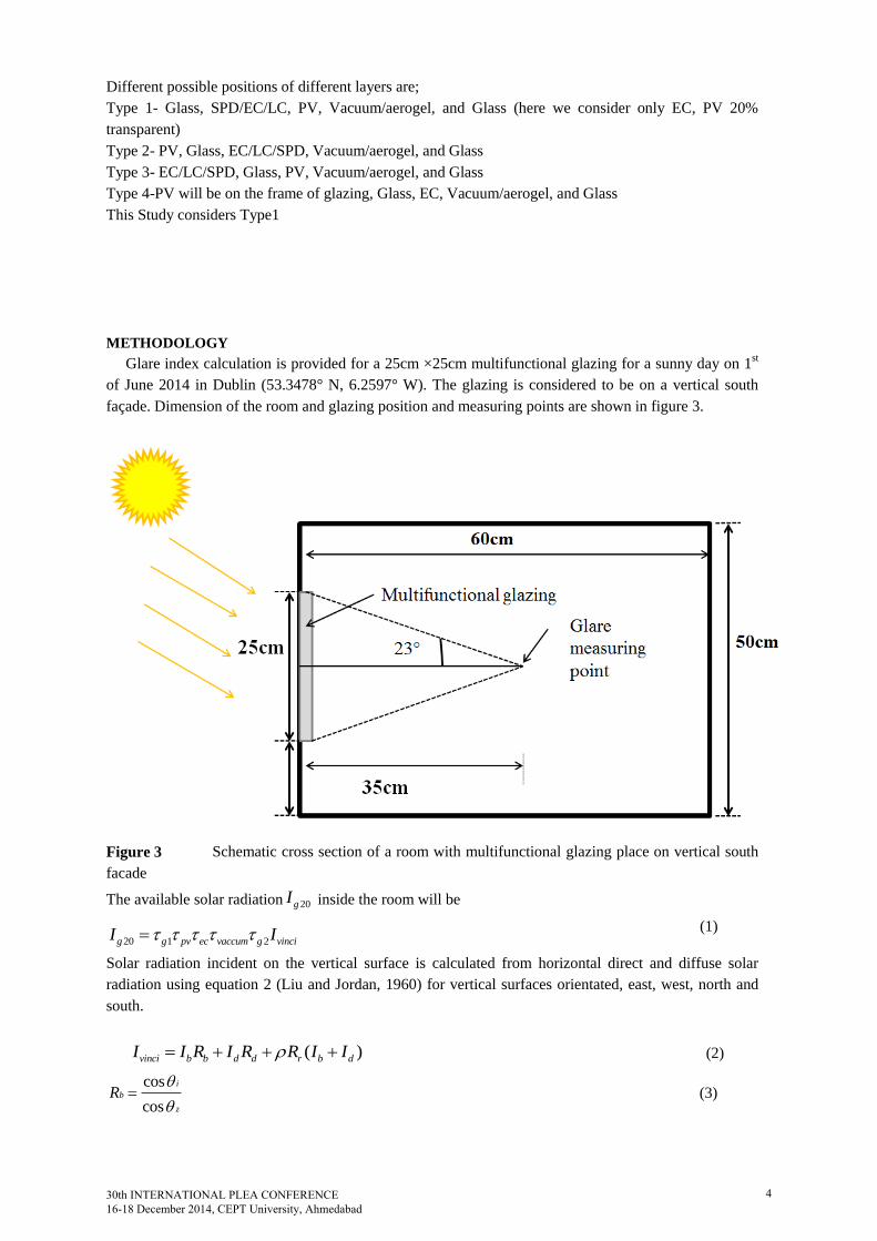
METHODOLOGY
Glare index calculation is provided for a 25cm ×25cm multifunctional glazing for a sunny day on 1st
of June 2014 in Dublin (53.3478° N, 6.2597° W). The glazing is considered to be on a vertical south
façade. Dimension of the room and glazing position and measuring points are shown in figure 3.
Figure 3 Schematic cross section of a room with multifunctional glazing place on vertical south
facade
The available solar radiation 20gI inside the room will be
20 1 2g g pv ec vaccum g vinciI I (1)
Solar radiation incident on the vertical surface is calculated from horizontal direct and diffuse solar
radiation using equation 2 (Liu and Jordan, 1960) for vertical surfaces orientated, east, west, north and
south.
( )vinci b b d d r b dI I R I R R I I (2)
cos
cos
i
b
z
R
(3)
30th INTERNATIONAL PLEA CONFERENCE 16-18 December 2014, CEPT University, Ahmedabad
4

1 cos
2dR
(4)
1 cos
2rR
(5)
Angle of incidence are given by
cos sin sin cos sin cos sin cos cos cos cos cos
cos sin sin cos cos cos sin sin sin
i
(6)
Global illuminance from the global incident solar radiation can be calculated from (Perez, 1990)
cos( ) ln( )vinci i i i iL I a bW c Z d
(7)
Discomfort glare is represented by glare index (GI) described by (Hopkinson and Collins 1970;
Hopkinson and Bradley 1960)
1.6 0.8
10 0.510log 0.478
0.07
s
ba s
LGI
L L
(8)
The standard glare values are 10 for just perceptible, 16 for just acceptable, 18.5 for borderline between
comfort and discomfort 22 for just uncomfortable and 28 for just intolerable.
RESULT & ANALYSIS
Vertical surface global solar radiation is illustrated for different orientation in figure 4. It can be seen that
receiving solar radiation on multifunctional glazing is possible during all the day in south facing
building. East facing and west facing glazing receive more solar radiation before 12 am and after 12am
respectively. For an East facing window in the morning variable transmission control of glazing is
essential whereas west facing windows needs control in the afternoon. South facing window needs
maintenance of glare and daylitghiting throughout the day
Figure 4 Incident global solar radiations for north east west and south on vertical surface
Glare index (GI) for south façade multifunctional glazing for switch off and switched on conditions
30th INTERNATIONAL PLEA CONFERENCE 16-18 December 2014, CEPT University, Ahmedabad
5
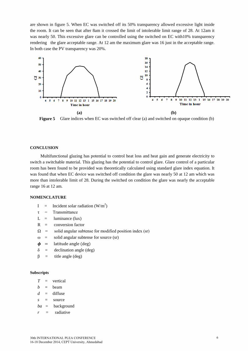
are shown in figure 5. When EC was switched off its 50% transparency allowed excessive light inside
the room. It can be seen that after 8am it crossed the limit of intolerable limit range of 28. At 12am it
was nearly 50. This excessive glare can be controlled using the switched on EC with10% transparency
rendering the glare acceptable range. At 12 am the maximum glare was 16 just in the acceptable range.
In both case the PV transparency was 20%.
(a) (b)
Figure 5 Glare indices when EC was switched off clear (a) and switched on opaque condition (b)
CONCLUSION
Multifunctional glazing has potential to control heat loss and heat gain and generate electricity to
switch a switchable material. This glazing has the potential to control glare. Glare control of a particular
room has been found to be provided was theoretically calculated using standard glare index equation. It
was found that when EC device was switched off condition the glare was nearly 50 at 12 am which was
more than intolerable limit of 28. During the switched on condition the glare was nearly the acceptable
range 16 at 12 am.
NOMENCLATURE
= Incident solar radiation (W/m2)
τ = Transmittance
L = luminance (lux)
R = conversion factor
Ω = solid angular subtense for modified position index (sr)
ω = solid angular subtense for source (sr)
𝝓 = latitude angle (deg)
δ = declination angle (deg)
β = title angle (deg)
Subscripts
T = vertical
b = beam
d = diffuse
s = source
ba = background
r = radiative
30th INTERNATIONAL PLEA CONFERENCE 16-18 December 2014, CEPT University, Ahmedabad
6

REFERENCES
Ahmed, A.A.E M.M.A. 2012. Using simulation for studying the influence of vertical shading devices on
the thermal performance of residential buildings (Case study: New Assiut City). Ain Shams
Engineering Journal, 3:163–174
Barrios, D., Vergaz, R., Pena, J.M.S.N., Granqvist, C.G., Niklasson, G.A. 2013. Toward a quantitative
model for suspended particle devices: Optical scattering and absorption coefficients. Solar Energy
Materials & Solar Cells, 111:115–122
Chow, T.T., Qiu, Z., Li C. 2009. Potential application of ‘‘see-through’’ solar cells in ventilated glazing
in Hong Kong. Solar Energy Materials & Solar Cells, 93: 230–238
Collins ,R.E., Robinson, S.J. 1991. Evacuated glazing .Solar Energy, 47:27-38
Collins, R.E., Simko, T.M. 1998. Current status of the science and technology of vacuum glazing. Solar
Energy, 62: 189-213
Deb,S.K., Lee,S.H., Tracy,C. E., Pitts, J. R., Gregg, B. A., Branz, H.M., 2001. Standalone photovoltaic
powered electrochromic smart window. Electrochim. Acta, 46: 2125–2130
Fang, Y., Eames, P.C., Norton, B., Hyde, T.J. 2006. Experimental validation of numerical model for heat
transfer in vacuum glazing. Solar Energy, 80: 564-577
Fang, Y., Eames, P.C., Norton, B. 2007. Effect of glass thickness on the thermal performance of
evacuated glazing. Solar Energy, 81: 395-404
Fang, Y., Eames, P.C., Norton, B., Hyde, T., Huang, Y., Hewitt, N. 2008. The thermal performance of
an electrochromic vacuum glazing with selected low-emittance coatings. Thin Solid Films, 516:
1074–1081
Freewan, A.A.Y. 2014. Impact of external shading devices on thermal and daylighting performance of
offices in hot climate regions. Solar Energy, 102:14–30
Galasiu, A.D., Atif, M.R., MacDonald, R.A. 2004. Impact of window blinds on daylight-linked dimming
and automatic on/off lighting controls. Solar Energy, 76: 523–544
Granqvist, C.G. 2000. Electrochromic tungsten oxide films: Review of progress 1993-1998. Solar
Energy Materials & Solar Cells, 60: 201- 262
Granqvist, C.G., Avendan, E., Azens, A. 2003. Electrochromic coatings and devices: survey of some
recent advances .Thin Solid Films, 442: 201–211
Granqvist, C.G. 2005. Electrochromic devices. Journal of the European Ceramic Society, 25: 2907–2912
Granqvist, C.G. 2012. Oxide electrochromics: An introduction to devices and materials. Solar Energy
Materials & Solar Cells, 99: 1–13
Hopkinson,R.G., Collins,J.B. 1970. Ergonomics of lighting. MacDoanld,ondon, great Britain
Hopkinson,RG., Bradley R.C. 1960. A study of glare from very large sources. Illuminating Engineering,
55: 288-294
Huang ,L.M., Hu, C.W., Liu, H.C., Hsu, C.Y., Chen, C. H., Ho, K.C. (2012), Photovoltaic
electrochromic device for solar cell module and self-powered smart glass applications. Solar Energy
Materials & Solar Cells, 99:154–159
Huang, L.M., Kung, C.P., Hu, C.W., Peng, C.Y., Liu, H.C. 2012. Tunable photovoltaic electrochromic
device and module. Solar Energy Materials & Solar Cells, 107: 390–395
Jensen, K.I., Schultz, J.M., Kristiansen, F.H. 2004. Development of windows based on highly insulated
aerogel glazings. Journal of Non-Crystalline Solids, 350: 351-357
Lee, E.S., DiBartolomeo, D.L., Rubinstein F.M., Selkowitz S.E. 2004. Low-cost networking for dynamic
window systems. Energy and Buildings, 36:503–513
Lee E.S., Tavil A. 2007. Energy and visual comfort performance of electrochromic windows with
overhangs. Building and Environment, 42: 2439–2449
Liu, B.Y.H., Jordan, R.C. 1960. The interrelationship and characteristic distribution of direct, diffuse and
total solar radiation. Solar Energy, 4:1-19
Miyazaki, T., Akisawa, A., Kashiwagi T. 2005. Energy savings of office buildings by the use of semi-
transparent solar cells for windows .Renewable Energy, 30: 281–304
Nazzal, A. 2005. A new evaluation method for daylight discomfort glare. International Journal of
Industrial Ergonomics, 35: 295-306
Papaefthimiou, S., Leftheriotis, G., Yianoulis, P., Hyde, T.J., Eames, P.C., Fang, Y., Pennarun, P. Y.,
Jannasch, P. 2006. Development of electrochromic evacuated advanced glazing Energy and
Buildings, 38: 1455–1467
Pennisi,A., Simone, F., Barletta G., Marco G.D., Lanza M.1999. Preliminary test of a large
electrochromic window. Electrochimica Acta, 44 : 3237-3243
30th INTERNATIONAL PLEA CONFERENCE 16-18 December 2014, CEPT University, Ahmedabad
7

Perez,R., Ineichen, P.,Seals R. 1990. Modelling daylight availability and irradiance components from
direct and global irradiance. Solar Energy, 44: 271-289
Robinson,S.J., Collins, R.E. 1989. ISES Solar world congress, International Solar Energy Society, Kobe,
Japan
Rosseinsky, D.R., Mortimer, R.J. 2001. Electrochromic systems and the prospects for devices .Advanced
Materials, 13: 783–793
Schultz, J.M., Jensen, K.I. 2008. Evacuated aerogel glazings .Vacuum, 82:723-729
Schultz, J.M., Jensen, K.I., Kristiansen, F.H. 2005. Super insulating aerogel glazing, Solar Energy
Materials & Solar Cells, 89: 275-285
30th INTERNATIONAL PLEA CONFERENCE 16-18 December 2014, CEPT University, Ahmedabad
8