multifrequency video generator for monitors gv-241
TRANSCRIPT

- 23 -
MULTIFREQUENCY VIDEO GENERATORFOR MONITORS
GV-241
1 GENERAL OBSERVATIONS
1.1 Description
The GV-241 Multifrequency Video Generator for Monitors is anequipment designed to be able to adjust and repair video monitors ofdifferent horizontal and vertical deflection frequencies, since it isequipped with the basic features of the different deflection systems mostcommonly used in personal computers (PCs).
The number of systems implemented depends on thecharacteristics of the particular unit, the limit being 32. The differentsystems are divided into two groups, in order to make their selectioneasier. The basic model has 29 systems distributed in two groups of 5and 24 respectively. The number and type of systems, in addition to thedistribution of the groups, can be modified upon request.
The GV-241 has eight selectable test patterns in all the systemsthat enable basic adjustments to be made to any monitor and anomaliesto be detected by means of visual inspection of the image.
It has three types of connector connecting directly to the monitor:D9 for Hercules, CGA and EGA monitors; D15 for MAC II monitors andminiature D15 for VGA monitors. It also has the individual outputconnections: R, G, B, CVS (video output without synchronism), HS(horizontal synchronism), VS (vertical synchronism) and CS (compositesynchronism output) by means of BNC connectors.
In order to avoid possible damage to the monitors, while thesystem is being selected the output connectors remain inhibited until theuser confirms the system selected.
It is possible to modify the polarity of the vertical and horizontalsynchronism at one's discretion from the front, or work in AUTO mode,the polarity in this case being that implemented in the system selected.
An LCD display is responsible for interaction with the user,displaying the pattern and the system selected at all times.
04/98 GV-241

- 24 -
Its great operational simplicity, small size and considerablerobustness make the GV-241 a piece of equipment that is particularlyuseful for meeting all the needs of Technical Assistance Services.
04/98 GV-241

- 25 -
1.2 Specifications
SYSTEMS
FIRST GROUP (p)
System Pixels Frequency PAH(µs)
SH(µs)
PPH(µs)
PAV(ms)
SV(ms)
PPV(ms)
Polarity Interlace
Horiz (kHz) Vert (Hz) H V
VGA 640x480 31.469 59.94 0.636 3.813 1.907 0.318 0.064 1.048 - - NO
VESA 800x600 37.879 60.317 1 3.2 2.2 0.026 0.106 0.607 + + NO
VESA 1024x768 48.363 60.004 0.369 2.092 2.462 0.062 0.124 0.6 - - NO
ATT 1280X1024 63.953 59.938 0.727 1.018 2.255 0.016 0.078 0.579 - - NO
Sun 1600X1280 89.2 66.9 0.001 2.03 1.4 0.011 0.112 0.471 + +
SECOND GROUP (s)
System Pixels Frequency PAH(µs)
SH(µs)
PPH(µs)
PAV(ms)
SV(ms)
PPV(ms)
Polarity Interlace
Horiz (kHz) Vert (Hz) H V
CGA, EGA 640x200 15.81 61.5 6.6 4.2 7.2 1.58 0.19 2.15 + + NO
MDA, Hercu 720X350 18.42 49.91 0.6 8.25 1.45 0.001 0.9 0.2 + - NO
EGA Hi 640X350 21.86 59.72 0.001 4.9 1.6 0.001 0.6 0.08 + + NO
VGA 640X350 31.469 70.09 0.636 3.813 1.907 1.176 0.064 1.902 + - NO
VGA 640X400 31.469 70.09 0.636 3.813 1.907 0.318 0.064 1.112 - + NO
VGA Text 720X400 31.48 70.11 0.635 3.812 1.906 0.304 0.063 1.111 - + NO
VESA 720X400 37.736 90.044 0.75 1.25 4.5 0.239 0.08 0.981 - +
VESA 640X350 37.86 84.136 0.762 1.27 6.603 0.924 0.079 1.638 + -
MAC II 840X480 35 66.67 2.116 2.116 3.175 0.084 0.086 1.114 + + NO
VESA 800X600 35.156 56.25 0.667 2 3.556 0.028 0.057 0.626 +/- +/-
VESA 640X480 37.86 72.809 0.762 1.27 4.603 0.238 0.079 0.74 - -
8514 1024X768 35.522 86.96 0.178 3.92 1.247 0.014 0.112 0.563 + + YES
SVGA 72Kc 800X600 48.09 72.01 1.121 2.399 1.279 0.479 0.124 0.774 + +
1025x768 1025X768 48.3 60 0.369 2.092 2.462 0.062 0.124 0.6 - - NO
SONY Std1 1024X768 48.78 60 1 1.5 2 0.061 0.061 0.799 + + NO
DEC 1024X864 54 60 0.16 1.85 1.68 0.001 0.056 0.629 + +
XGA 1024X768 56.5 70 0.32 1.813 1.92 0.053 0.106 0.513 - - NO
57K/72H 1024X768 57.09 72 0.32 1.77 1.87 0.054 0.103 0.5 + +
Radius 1152X882 66 72 0.138 1.28 2.42 0.001 0.2 0.38 + +
MAC II TP 1152X870 68.681 75.06 0.32 1.28 1.44 0.043 0.043 0.567 - - NO
Samsung 1006X1048 62.8 59.8 0.15 1.88 1.58 0.001 0.127 0.542 + +
SONY Std 2 1280X1024 63.337 59.98 0.407 1.701 1.849 0.047 0.047 0.41 + + NO
DEC 1280X1024 70.7 66.5 0.267 1.33 1.87 0.042 0.042 0.467 + +
Arts. Graf 1280X1024 78 73 0.228 0.915 1.907 0.038 0.038 0.488 + +
04/98 GV-241

- 26 -
TOLERANCESHorizontal frequency deviation ±1 %Vertical frequency deviation ±1,5 %
TEST PATTERNSAvailable test patterns 8
1 Colour bars 100/0/100/02 Red3 Green4 Blue5 Range of greys. Seven steps of equal width varying from black
to white. 6 Crosshatch. 15 white vertical lines and 11 white horizontal lines
that maintain a ratio of 4:3 in all the systems, within a whiteasymmetrical frame, with the outer edge in accordance with thelimits of the system. The vertical lines have a duration of 125ns, 62 ns or 31 ns, depending on the system.
7 Multiburst. Horizontal line divided into nine blocks. It begins witha 50% grey and continues 8 MHz, 16 MHz, 4 MHz, 16 MHz, 4MHz, 16 MHz, 8 MHz and 50% grey.
8 100% white, with a rectangle of grey (approx. 70%) in the topleft part to identify the direction of deflection.
OUTPUTS R,B Red and blue signalsAmplitude 0.7 VppImpedance 75 ΩConnector BNC
04/98 GV-241

- 27 -
OUTPUT G Green signal output with selectablesynchronism
Amplitude 0.7 VppImpedance 75 ΩConnector BNC
OUTPUT CVS Video signalAmplitude 0.7 VppImpedance 75 ΩConnector BNC
OUTPUT HS Horizontal synchronism pulseSignal TTLConnector BNC
OUTPUT VS Vertical synchronism pulseSignal TTLConnector BNC
OUTPUT CS Composite synchronism (horizontaland vertical) of fixed polarity (negativedirection).
Signal TTLConnector BNC
OUTPUTS C1, C2, C3 Connectors D9, D15 miniature andD15 respectively. Direct connectionswith the monitor according to thecharacteristics described earlier andwith the connections of section 5.
D9 connector outputs are all TTL.When selecting test patterns number 1or 5 a black and white image willappear. When using an Herculesmonitor, R,G,B test patterns will beblack.
POWER REQUIREMENTSMains voltage AC 110-125-220-230-240 V ± 10%Mains frequency 50-60 HzConsumption 9 W
OPERATING ENVIRONMENTAL CONDITIONSMax. altitude 2000 mTemperature range From 5 ºC to 40 ºCMaximum relative humidity 80% (Up to 31 ºC), linearly decreasing
to 50% at 40 ºC.
04/98 GV-241

- 28 -
MECHANICAL CHARACTERISTICSDimensions W.212 x H.102 x D.241 mmWeight 2.4 kg
ACCESSORIES INCLUDED90901105 Power Cable CA-05
04/98 GV-241

- 29 -
2 SAFETY RULES
* Use thie equipment connected only to devices or systems with theircommon at ground potential.
* This is a class I equipment, for safety reasons it should beconnected to supply lines with the corresponding earth terminal.
* This equipment can be used in Category II installations and PollutionDegree 1 environments.
* When using any of the following accessories use only the specifiedones to ensure safety.
Power cord
* Observe all specified ratings both of supply and measurement.
* Remember than voltages higher than 60 V DC or 30 V AC rms arepotentially dangerous.
* Always observe the maximum specified environmental conditions forthe equipment.
* The user is only authorized to carry out the following maintenanceoperations:
Change the mains fuse, which should be of the type and valueindicated.
Specific instructions are given for this action in the Maintenancesection.
Any other change in the equipment should only be undertaken byspecialised personnel.
* The output negative is at ground potential.
* Do not obstruct the equipment´s ventilation system.
* Strictly follow the cleaning recommendations that are described inthe Maintenance section.
* Use for signal outputs appropriate low radiation leads.
04/98 GV-241

- 30 -
* Symbols related with safety
DIRECT CURRENT
ALTERNATING CURRENT
DIRECT AND ALTERNATING
GROUND TERMINAL
PROTECTIVE CONDUCTOR
FRAME TERMINAL
EQUIPOTENTIALITY
ON (Supply)
OF (Supply)
DOUBLE INSULATION PROTECTED(CLASS II Protection)
CAUTION(Risk of electric shock)
CAUTION REFER TO ACCOMPANYINGDOCUMENTS
FUSE
04/98 GV-241
- 31 -
3 INSTALLATION
3.1 Power supply
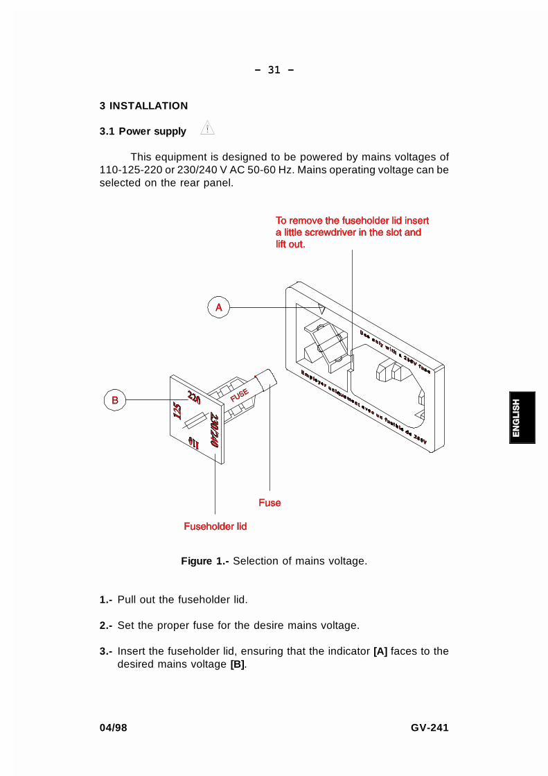
This equipment is designed to be powered by mains voltages of110-125-220 or 230/240 V AC 50-60 Hz. Mains operating voltage can beselected on the rear panel.
Figure 1.- Selection of mains voltage.
1.- Pull out the fuseholder lid.
2.- Set the proper fuse for the desire mains voltage.
3.- Insert the fuseholder lid, ensuring that the indicator [A] faces to thedesired mains voltage [B].
04/98 GV-241

- 32 -
31ED9?>*
D85 5AE9@=5>D 9C 613D?BI C5D 6?B "" F ?@5B1D9>7
F?<D175
256?B5CG9D389>7 ?>D89C 9>CDBE=5>D C5D D85F?<D175
C5<53D?B D? D85 @B?@5B @?C9D9?> 1>4 25 CEB5 D81D D85
6EC5 F1<E5 9C 133?B49>7 D? D85 =19>C F?<D175
3.2 Installation
The equipment is prepared for use as a desktop unit.
04/98 GV-241

- 33 -
4 OPERATING INSTRUCTIONS
4.1 Controls description
Figure 2.- Front panel.
[1] LINEOn-off switch.
[2] Pattern code indicator panel.
[3] Alphanumeric display. Provides information about the group,pattern and system selected.
[4] ENTSystem confirmation key.
[5] SELGroup, system and pattern selection key.
[6]Upward shift key.
[7]Downward shift key.
[8] CS
04/98 GV-241

- 34 -
Composite synchronism signal output.
[9] VSVertical synchronism signal output.
[10] HSHorizontal synchronism signal output.
[11] 15-pin D connector.
[12] CVSVideo signal without synchronism output.
[13] Miniature 15-pin D connector.
[14] BB signal output.
[15] GG signal output with or without synchronisms
[16] 9-pin D connector.
[17] RR signal output.
[18] V+/V-In manual synchronism mode:
Negative or positive vertical synchronism keyIn automatic synchronism mode:
When pushed provides the G + synchronism signal on the Goutput [15]
[19] H+/H-Positive or negative horizontal synchronism key.
[20] AUTO/MANUALSynchronism polarity manual or automatic selection key.
04/98 GV-241

- 35 -
4.2 Start-up
Connect the unit to the mains.
Press the LINE [1] switch, whereupon the LCD display [3] will lightup and the following information will appear on it:
- Group of systems in which the generator is located (p for thefirst and s for the second).
- Pattern selected in accordance with the indicator panel [2] (1colour bar).
- System selected (blinking).
Initially the outputs are inhibited and the cursors are in a positionto change the pattern.
4.3 Method of using
The GV-241 enables the user to change pattern and system oralter the polarity of the synchronism easily and simply using the frontkeyboard, while the status of the outputs is observed through theindications that appear on the LCD display.
Figure 3.- Display
The indications that appear on the display are the following:
A.- p indicates that the first group of systems has been selected(table nº 1).s indicates that the second group of systems has beenselected (table nº 2).
04/98 GV-241

- 36 -
B.- 1-8 indicates the pattern present in the outputs. This can berecognised by means of the indicator panel printed on thefront [2].
C.- Indicates the name of the system selected. If this is flashing,it indicates that the outputs are inhibited.
D.- When lit up, this indicates that it is possible to change
systems group by progressive use of the cursors [6] and
[7] .
E.- When lit up, this indicates that it is possible to change
pattern by progressive use of the cursors [6] and [7] .
F.- When lit up, this indicates that it is possible to change
system by progressive use of the cursors [6] and [7] .
When this generator is used, the required system and the groupof which it forms a part (table 1 and 2 of the specifications section) mustbe known. In the event that the system chosen is not implemented, it ispossible to look for one that has similar characteristics or request that anew personal table be made.
Change of systems group.If line D is not lit up, press the SEL [5] key until it lights up.
Then press the cursors [6] and [7] until the group chosencan be read. Every time the group is changed, the outputs willbe inhibited and the system indicator (F) will flash.
Change of system.If line F is not lit up, press the SEL [4] key until it lights up.
Then press the cursors [6] and [7] until the systemchosen can be read. Every time the system is changed, theoutputs will be inhibited and the system indicator (F) will flash.
Change of pattern.If line E is not lit up, press the SEL [5] key until it lights up.
Then press the cursors [6] and [7] until the patternchosen can be read.
Confirmation.Once the system has been selected, by pressing the ENT [4]key the outputs will be no longer be inhibited and the desiredsignals in connections [8] to [17] will be obtained.
04/98 GV-241

- 37 -
Synchronism polarity.With the AUTO-MANUAL [20] key the desired polarity in thesynchronism signals can be obtained. In the AUTO position thepolarity is that implemented in the system; in the MANUALposition the polarity of the vertical and horizontal synchronismcan be selected at the user's discretion by means of keys V+/V-[18] and H+/H- [19].
The outputs will be inhibited when the generator is connectedfor the first time, whenever the ENT [4] key is pressed andevery time the group or system is changed.
04/98 GV-241

- 38 -
5 DESCRIPTION OF THE OUTPUT CONNECTORS
5.1 Output connectors
9-pin D connector [16]Pin Nº Signal1 GND2 NC3 R4 G5 B6 NC7 VIDEO8 HS9 VSConnections for Hercules, CGA and EGA monitors.
15-pin miniature D connector [13]Pin Nº Signal1 R2 G3 B4 NC5 GND6 GND7 GND8 GND9 NC10 NC11 NC12 NC13 HS14 VS15 NCConnections for VGA monitors.
04/98 GV-241

- 39 -
15-pin D connector [11]Pin Nº Signal1 GND2 R3 CS4 NC5 G6 GND7 NC8 NC9 B10 NC11 GND12 VS13 GND14 GND15 HSConnections for MAC II monitors.
04/98 GV-241

- 40 -
04/98 GV-241

- 41 -
6 PRINCIPLE OF OPERATION
OscillatorQuartz-controlled generator of the base frequency of the system (32MHz). This frequency is divided (divider) by 2, 4 and 8 to obtain 16MHz, 8 MHz and 4 MHz in order to control the counters andgenerate the multiburst signal.
EPROMsThe two EPROM memories that contain the characteristics of thehorizontal and vertical exploration of the systems implemented areread with counters (counter), the horizontal with a clock frequency of8 MHz and the vertical with a frequency FH/2 read in the horizontalmemory. The data obtained in the outputs of the two memories passthrough a D/A converter, an adjustable amplifier and somecomparators in whose outputs the basic signals of the systemsgenerated are obtained (RH, VSH, MARCH, SH, BH, CV, VSV,MARCV, SV, BV and RV). The changes of system are made bycontrolling the different memory banks with part of the addressingbits, with some elements controlled by a I2C bus (PCF8574).
Pattern generatorThe various patterns of this generator are obtained both in the RGBand VIDEO configurations on the basis of the VSC, MARCH, VSVand MARCV signals, with the times appropriate to each system. Theselection of patterns is controlled by the I2C bus (PCF8574). Thehorizontal and vertical synchronism signals (SH AND SV) can becontrolled with the AUTO-MANUAL commutator to invert the directionof each of these. In the automatic position the polarity of thesesignals is defined by the I2 bus. The RGB, video and synchronismsignals pass through some impedance-matching elements (Buffer)before reaching the output connectors. The possible outputconnections are one in any of the three D connectors and another inthe BNC connectors.
µPThe microprocessor controls the Keyboard, the LCD DISPLAY andthe COUT inhibition control, and generates the I2C bus for the controlof the memories and the pattern generator.
04/98 GV-241

- 42 -
04/98 GV-241

- 43 -
7 MAINTENANCE
7.1 Replacement of the mains supply fuse
The fuseholder is situated in the actual mains socket and is initself the mains supply voltage selector (see figure 1, section 3.1 Powerrequirements).
To replace the fuse, disconnect the power cable.
Remove the fuseholder cover using a suitable screwdriver.
Replace the damaged fuse with another of the followingcharacteristics:
THE FUSE SHOULD BE OF THE TYPE: 5x20 mm, 250V, T, AND:
125 mA FOR 220, 230/240 V250 mA FOR 110 AND 125 V
When putting the fuseholder cover back, ensure that the voltageselector is situated in a position that corresponds to the mains supplyvoltage.
7.2 Cleaning recommendations
CAUTION
To clean the cover, take care the instrument is disconnected.
CAUTION
Do not use scented hydrocarbons or chlorized solvents as cleaningagents. These products may damage the material used in theconstruction of the cover.
04/98 GV-241

- 44 -
The cover should be cleaned using a light solution of detergentand water applied soft wetted cloth.
Dry completely before using the equipment again.
04/98 GV-241

- 21 -
TABLE OF CONTENTS
1 GENERAL OBSERVATIONS . . . . . . . . . . . . . . . . . . . . . . . . . . 231.1 Description . . . . . . . . . . . . . . . . . . . . . . . . . . . . . . . . . . . 231.2 Specifications . . . . . . . . . . . . . . . . . . . . . . . . . . . . . . . . . 24
2 SAFETY RULES . . . . . . . . . . . . . . . . . . . . . . . . . . . . . . . . . . 27
3 INSTALLATION . . . . . . . . . . . . . . . . . . . . . . . . . . . . . . . . . . . 293.1 Power supply . . . . . . . . . . . . . . . . . . . . . . . . . . . . . . . . . . 293.2 Installation . . . . . . . . . . . . . . . . . . . . . . . . . . . . . . . . . . . . 30
4 OPERATING INSTRUCTIONS . . . . . . . . . . . . . . . . . . . . . . . . . 314.1 Controls description . . . . . . . . . . . . . . . . . . . . . . . . . . . . . 314.2 Start-up . . . . . . . . . . . . . . . . . . . . . . . . . . . . . . . . . . . . . . 334.3 Method of using . . . . . . . . . . . . . . . . . . . . . . . . . . . . . . . . 33
5 DESCRIPTION OF THE OUTPUT CONNECTORS . . . . . . . . . . 355.1 Output connectors . . . . . . . . . . . . . . . . . . . . . . . . . . . . . . 35
6 PRINCIPLE OF OPERATION . . . . . . . . . . . . . . . . . . . . . . . . . 37
7 MAINTENANCE . . . . . . . . . . . . . . . . . . . . . . . . . . . . . . . . . . . 397.1 Replacement of the mains supply fuse . . . . . . . . . . . . . . . . 397.2 Cleaning recommendations . . . . . . . . . . . . . . . . . . . . . . . . 39
04/98 GV-241