multiflite nano b fc v1 · multiflite nano-b-fc v1.0 user guide page 1 of 10 introduction this...
TRANSCRIPT

MULTIFLITE
NANO-B-FC V1.0 USER GUIDE
MULTIFLITE NANO-B-FC V1.0 USER GUIDE
Page 1 of 10
Introduction This flight controller is designed for mini and micro brushed quadcopters/hexacopters with a bunch of important
features crammed into a tiny 30x30mm board with a header for expansion resulting in a small, light, and
expandable flight controller.
NOTE: Please do not make copies or use any content from this guide without written permission.
Feature List Baseflight & Cleanflight firmware compatible
30 x 30mm
2.9g
Single side populated (for super easy mounting)
MPU6050
Baro pads (not populated currently)
Mag pads (not populated currently)
Brushed motor support up to 6 motors (all populated with fets)
RC5 and RC6 broken out (these become M7 and M8 for octo configuration (you would need your own
fets however))
6.3A N Channel fets
Flight battery voltage monitoring
Spektrum Satellite (3.3V) or PPM (VBATT) RX input
Spektrum bind button (hold on boot to bind)
RSSI PWM to Analog (RC circuit) on ADC5
CH2, ADC5 pads available as solder pads
3.3V Buck/Boost regulator (no brownouts)
1S (4.2V) only
Expansion headers (SPI, SWDIO/SWCLK, Serial0, Serial1, CH7, CH8, 3.3V, VBATT, GND)
WS2812B LED header (including logic level converter)
Buzzer led for low battery alarm
Buzzer transistor either for physical buzzer or an red LED
Connectors all around edge and on both sides with labels
I2C pads broken out
3.3V pad for aux output
Recommended Reading The NANO-B-FC is based on the same pin out as the AbuseMark/AfroFlight NAZE32 so as a reference it is
worth reading the NAZE32 manual located here: http://www.abusemark.com/downloads/naze32_rev3.pdf
MULTIFLITE NANO-B-FC V1.0 USER GUIDE
Page 2 of 10
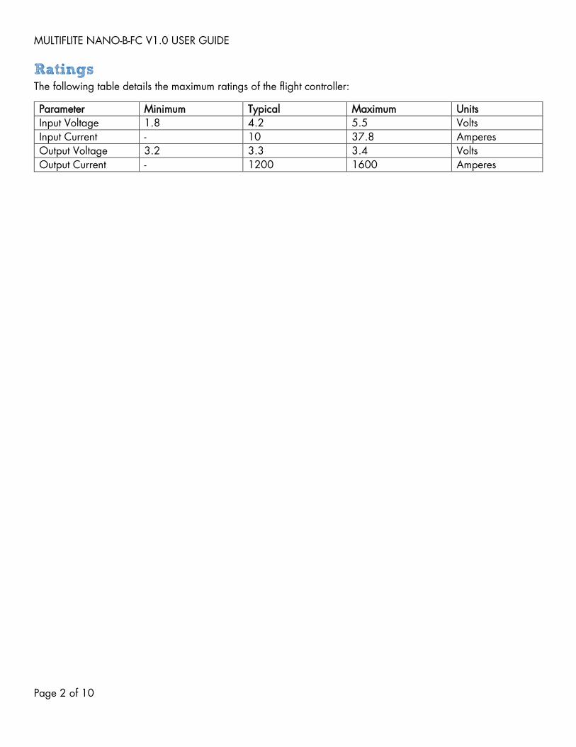
Ratings The following table details the maximum ratings of the flight controller:
Parameter Minimum Typical Maximum Units
Input Voltage 1.8 4.2 5.5 Volts
Input Current - 10 37.8 Amperes
Output Voltage 3.2 3.3 3.4 Volts
Output Current - 1200 1600 Amperes
MULTIFLITE NANO-B-FC V1.0 USER GUIDE
Page 3 of 10
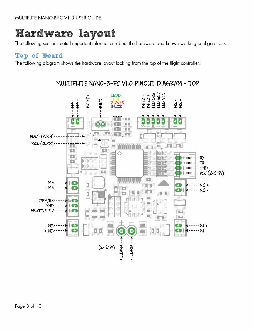
Hardware layout The following sections detail important information about the hardware and known working configurations:
Top of Board The following diagram shows the hardware layout looking from the top of the flight controller:
MULTIFLITE NANO-B-FC V1.0 USER GUIDE
Page 4 of 10
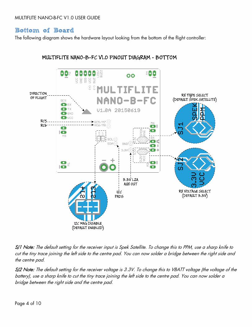
Bottom of Board The following diagram shows the hardware layout looking from the bottom of the flight controller:
SJ1 Note: The default setting for the receiver input is Spek Satellite. To change this to PPM, use a sharp knife to
cut the tiny trace joining the left side to the centre pad. You can now solder a bridge between the right side and
the centre pad.
SJ2 Note: The default setting for the receiver voltage is 3.3V. To change this to VBATT voltage (the voltage of the
battery), use a sharp knife to cut the tiny trace joining the left side to the centre pad. You can now solder a
bridge between the right side and the centre pad.

MULTIFLITE NANO-B-FC V1.0 USER GUIDE
Page 5 of 10
Expansion Header Connections The following diagram shows the hardware layout looking from the top of the flight controller, and focuses on the
expansion header:
Motor Mixer Settings The following diagram shows the motor rotation direction as well as which motor uses which pin:
Note that for Quad X and Hex X the motor outputs on the flight controller are positioned so that they are in the
correct corners (e.g. the Quad X bottom left motor is M1).

MULTIFLITE NANO-B-FC V1.0 USER GUIDE
Page 6 of 10
Header Example The following image shows the typical set up for each header. The Spek Satellite connection is best soldered on
and a small blob of hot glue placed over the top.
Spek Satellite Receiver Connection The following image shows the typical connection to a Spek Satellite (OrangeRX R100 shown in example
image). This is the same cable present in the image above.

MULTIFLITE NANO-B-FC V1.0 USER GUIDE
Page 7 of 10
Firmware Upgrade The following sections detail important information about upgrading the firmware of the flight controller and
some useful defaults when setting up your own.
Cleanflight Upgrading the firmware is as simple as pressing the “Firmware Updater” button in the Cleanflight GUI, selecting
the correct board (MFNBFC) or downloading the latest hex file from the multiFlite website, and then pressing
“Flash Firmware”.
If the existing firmware has become corrupt, or a bad version of firmware has been flashed, you will need to put
the flight controller into its bootloader mode. This is achieved by shorting the “BOOT0” pads (see pin out
diagram) while powering up the flight controller (using a Phillips/Pozidrive (+) shaped driver between the two
pads works best). If this has been done successfully then the flight controller will show a solid RED light, and all
others will be off. You can now press “Flash Firmware” and it will upload. If it does not, repeat this procedure.
MULTIFLITE NANO-B-FC V1.0 USER GUIDE
Page 8 of 10
Tips and Tricks The following section details some useful tips to get the most out of your flight controller. This section assumes
using Cleanflight firmware (default) but could be extrapolated to other firmware.
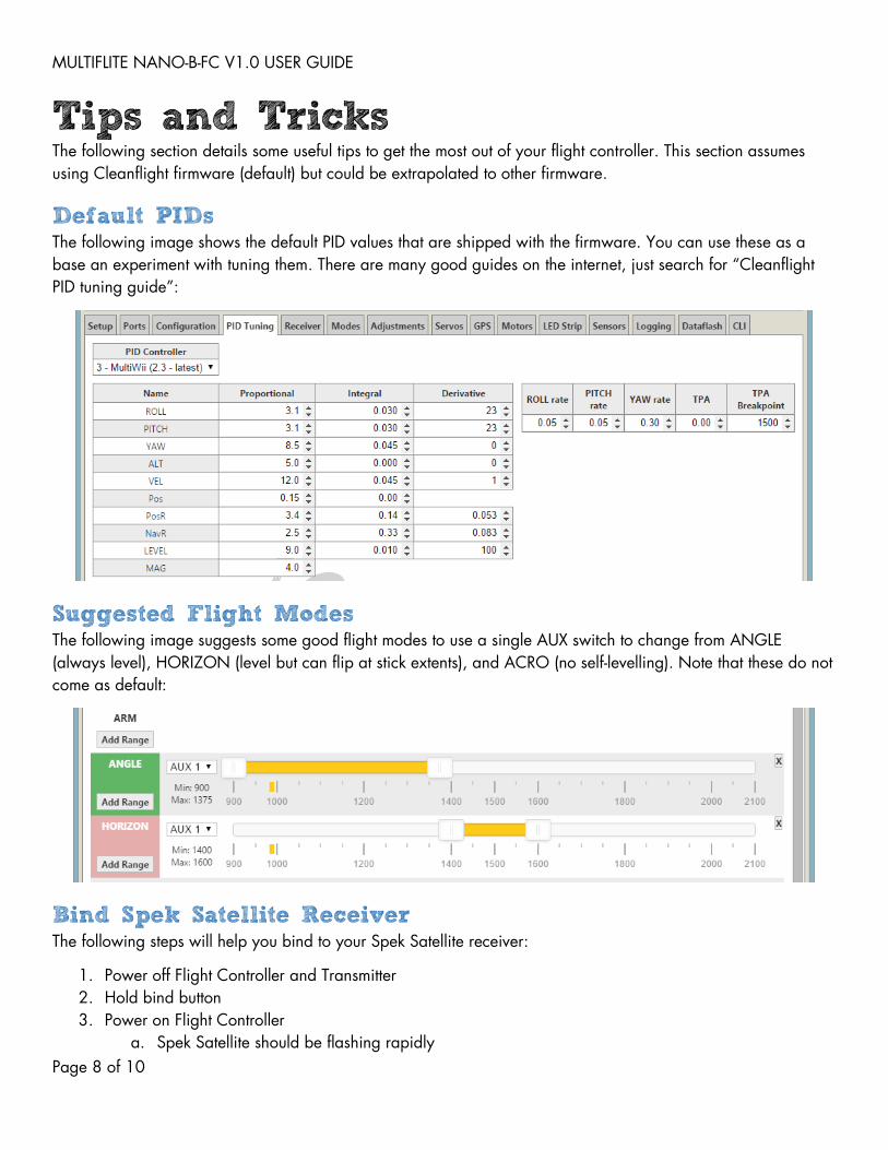
Default PIDs The following image shows the default PID values that are shipped with the firmware. You can use these as a
base an experiment with tuning them. There are many good guides on the internet, just search for “Cleanflight
PID tuning guide”:
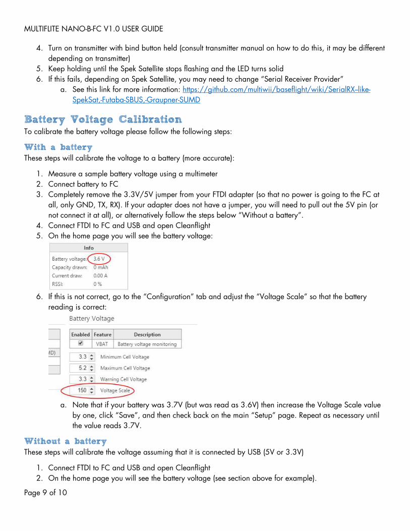
Suggested Flight Modes The following image suggests some good flight modes to use a single AUX switch to change from ANGLE
(always level), HORIZON (level but can flip at stick extents), and ACRO (no self-levelling). Note that these do not
come as default:
Bind Spek Satellite Receiver The following steps will help you bind to your Spek Satellite receiver:
1. Power off Flight Controller and Transmitter
2. Hold bind button
3. Power on Flight Controller
a. Spek Satellite should be flashing rapidly
MULTIFLITE NANO-B-FC V1.0 USER GUIDE
Page 9 of 10
4. Turn on transmitter with bind button held (consult transmitter manual on how to do this, it may be different
depending on transmitter)
5. Keep holding until the Spek Satellite stops flashing and the LED turns solid
6. If this fails, depending on Spek Satellite, you may need to change “Serial Receiver Provider”
a. See this link for more information: https://github.com/multiwii/baseflight/wiki/SerialRX--like-
SpekSat,-Futaba-SBUS,-Graupner-SUMD
Battery Voltage Calibration To calibrate the battery voltage please follow the following steps:
With a battery These steps will calibrate the voltage to a battery (more accurate):
1. Measure a sample battery voltage using a multimeter
2. Connect battery to FC
3. Completely remove the 3.3V/5V jumper from your FTDI adapter (so that no power is going to the FC at
all, only GND, TX, RX). If your adapter does not have a jumper, you will need to pull out the 5V pin (or
not connect it at all), or alternatively follow the steps below “Without a battery”.
4. Connect FTDI to FC and USB and open Cleanflight
5. On the home page you will see the battery voltage:
6. If this is not correct, go to the “Configuration” tab and adjust the “Voltage Scale” so that the battery
reading is correct:
a. Note that if your battery was 3.7V (but was read as 3.6V) then increase the Voltage Scale value
by one, click “Save”, and then check back on the main “Setup” page. Repeat as necessary until
the value reads 3.7V.
Without a battery These steps will calibrate the voltage assuming that it is connected by USB (5V or 3.3V)
1. Connect FTDI to FC and USB and open Cleanflight
2. On the home page you will see the battery voltage (see section above for example).

MULTIFLITE NANO-B-FC V1.0 USER GUIDE
Page 10 of 10
a. Note that this should read what your FTDI is set to (5V or 3.3V)
3. If this is not correct, go to the “Configuration” tab and adjust the “Voltage Scale” so that the battery
reading is correct (see section above for example).
a. Note that if your FTDI was set to 3.3V (but was read as 3.2V) then increase the Voltage Scale
value by one, click “Save”, and then check back on the main “Setup” page. Repeat as necessary
until the value reads 3.3V.