multiflex girder slab formwork - politechnika...
TRANSCRIPT

MULTIFLEXGirder slab formwork
Assembly Instructions for Standard Application
Edition 11/2007

Dokument 1 28.04.2005 12:48 Uhr Seite 1
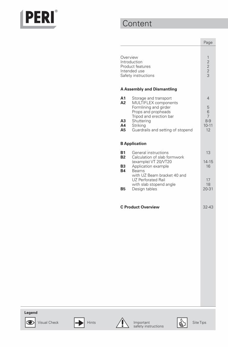
Overview 1Introduction 2Product features 2Intended use 2Safety instructions 3
A Assembly and Dismantling
A1 Storage and transport 4A2 MULTIFLEX components
Formlining and girder 5Props and propheads 6Tripod and erection bar 7
A3 Shuttering 8-9A4 Striking 10-11A5 Guardrails and setting of stopend 12
B Application
B1 General instructions 13B2 Calculation of slab formwork
(example) VT 20/VT20 14-15B3 Application example 16B4 Beams
with UZ Beam bracket 40 andUZ Perforated Rail 17with slab stopend angle 18
B5 Design tables 20-31
C Product Overview 32-43
Content
Page
Legend
Visual Check Hints Important Site Tipssafety instructions
1
4
3
6
1a
1b
5
2
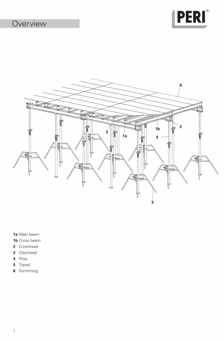
1a Main beam1b Cross beam2 Crosshead3 Clawhead4 Prop5 Tripod6 Formlining
Overview

2
These assembly instructions describethe standard usage of the flexibleMULTIFLEX slab formwork systemtogether with PERI VT 20 girders.
At the beginning, there is informationon the product and its utilisation aswell as general and safety references.In Part A the intended use, as of astandard situation, is presented.
Introduction
Individual components:– formlining sheets– PERI VT 20 girder and GT 24
lattice girder– crosshead as non-tilting
supporting heads of formwork– clawhead for intermediate support– erection bar for girder assembly
from below– tripod / MRK frame as erection aid.
Support:– PERI slab props and shoring system.
These Assembly Guidelines containinstructions for the correct handlingand intended use of the PERIMULTIFLEX slab formwork system.Safety instructions and load specifi-cations must be observed at all times.
Special permission must be givenby PERI if the formwork is to be used
Product features
The MULTIFLEX slab formwork is agirder formwork system which issuitable for every ground plan anddifferent heights, depending on thetype of support used.
Depending on the slab thickness,assembly can be carried out usingthree girder combinations:Combination 1: VT 20 / VT 20Combination 2: VT 20 / GT 24Combination 3: GT 24 / GT 24
Main beam and connected crossbeams form a grid to accommodatethe formlining sheets. The main beamsare positioned in the supporting headsof props.
Part B contains details on systemapplication, and design tables for propspacing, formlining and accessories.Information on appropriate props canbe found in the PERI Design Tables –Formwork Technology.
Additional details for forming withPERI GT 24 girders are contained inPart A and B.
The individual system components arelisted in the product overview togetherwith their article numbers. Dimensionswithout any unit of measurement arein cm.
If you have any questions, pleasecontact your local PERI representative.
Additional guidelines
In particular, this includes at thepresent time– industrial safety regulations
(BetrSichV)– technical regulations for industrial
safety (TRBS)
PERI product information
PERI design tables –formwork technologyPERI MULTIPROP / PEPPERI slab edge trestle AWPERI UZ beamPERI construction site equipmentStripping Cart ASW 465Pallets and stacking devicesApproval for PERI girdersType tests for slab props
Intended use
for other applications other than ithas been designed for together withsupplementary assembly instructions.
Basically, only materials in perfectcondition may be used. The safety andenvironmental regulations of eachcountry where this product is usedmust be observed at all times.
The product is intended for commercialuse only.
These assembly guidelines, PERIoffer and implementation plansas well as other PERI productinformation do not replace specificconstruction site work and assemblyinstructions.

Dokument 1 28.04.2005 12:48 Uhr Seite 1

3
11. Striking takes place only whenthe concrete has sufficiently hardenedand site management has given thego-ahead!
12. When striking, use tools whichdo not damage the MULTIFLEXcomponents! Do not pull awaycomponents with the crane!
13. When striking, do not compromisethe stability of shoring and formworkcomponents!
14. Only transport components withhoisting gear if suitable attachingmeans are available!
15. The weight of the componentsmust not exceed the permissible loadcapacity of the lifting gear!
16. Remove lifting equipment from alowered formwork component or unitonly when it is in a stable position!
17. Store and transport componentsand pallets in a safe and secure manneravoiding any unintentional changeof position! Do not throw anycomponents!
Maintenance instruction forformlining
Immersion vibrator with rubber capminimises damage to the formlining.
Take care when placing heavy objectson formlining. Use timbers wherenecessary and be aware of load bearingcapacity.
Use reinforcement spacers with alarge bearing area to minimiseindentations.
Safety Instructions
These assembly instructions aredirected at those persons who workwith PERI MULTIFLEX.Non-observance of the safetyinstructions and assembly guidelinescan lead to accidents and damage tomaterials.
General information
– The basis of the MULTIFLEX systemis an all-sided horizontal andnon-moveable positioned slabformwork! This is given withperipheral walls and beams castin advance. Otherwise the transferof horizontal loads must be ensuredin accordance with DIN 4421through other measuresundertaken on site (e.g. bracing)!
– If bracing is required for cantilevers,this must be friction-lockedassembled!
– For supporting pre-fabricatedslab elements, manufacturer´sreferences and installationinstructions must be observed!
– The correct working loads forprops and girders is ensured withthe help of PERI design tables andthe respective building authorityapproval.
– The safe and secure installationof the bracing as well as assemblyof the shoring (including tripod,crosshead and clawhead) are to bedescribed in detail in thecontractor`s assembly instructions!
Responsibilities of the contractor:
1. The contractor must ensure thatthe PERI and all other requiredinstructions are at the user´s disposal.
2. All persons working with theproduct must be familiar with thecontent of these instructions andsafety information.
3. Persons who cannot or havedifficulty in reading and understandingthese instructions must inform andthen be fully briefed by the contractor.
4. The contractor has to ensure thatassembly, adjusting and dismantling,moving as well as correct use of theproduct is supervised by trained andauthorised personnel.
5. The contractor is obliged to provideall prerequisites to ensure compliancewith applicable safety regulations.
General Safety Information:
1. MULTIFLEX slab formworkcomponents are to be checked beforeevery use for signs of damage!Damaged parts are to be replacedby PERI original components!
2. When erecting the MULTIFLEX,ensure that all load effects are safelytransferred! The formwork must remainin a horizontal and non-moveableposition!
3. MULTIFLEX must be assembledon a flat, clean and sufficiently load-bearing surface!
4. Stability must be guaranteed at alltimes!
5. Never remove safety installations!
6. Do not exceed any givenpermissible loads!
7. Safe working areas are requiredat all times for assembly, adjusting,dismantling and moving of theformwork equipment
8. Safe access to all working areasmust be in place!
9. Working areas must be madesecure against falling!
10. Safe conditions for forming mustbe available at all times! Appropriatesafety precautions are to be in placeduring unfavourable weather conditionse.g. secure formwork against lifting!Site personnel must not enterjeopardized areas!

4
A1 Storageand Transport
– PERI Instructions for Use: Pallets!BGR 500 operated by equipment -Pallets and stacking devices areattached by means of suitable andreliable lifting equipment to all fourdesignated lifting eyes!
– Secure components in the ringpallets against moving!(e.g. tension belt or steel band)
Storage
Stacked materials and pallets mustbe protected against effects of theweather, e.g. secure formliningagainst lifting.
Store and transport MULTIFLEXcomponents in craneable PERI ringpallets and PERI crate pallets,see also A3 / A4.Alternatively, stack girders andformlining using edge protection andstored on timbers.
Transport
Load-bearing capacity!
– PERI ring pallets and crate palletsare suitable for crane and fork-liftoperations. Lifting equipment mustbe attached to all four lifting eyes 10.They can also be moved using thePERI pallet lifting trolley.
– Both containers can be lifted usingboth the long and short sides. For safetransportation, the length of the liftingforks must be adjusted accordingly.
– Move stacks by means of suitablelifting gear.
Fig.1c
Fig.1b
10
10
10
Fig.1d
Fig.1a
10
10
5
16,3
16,3
A2 Components
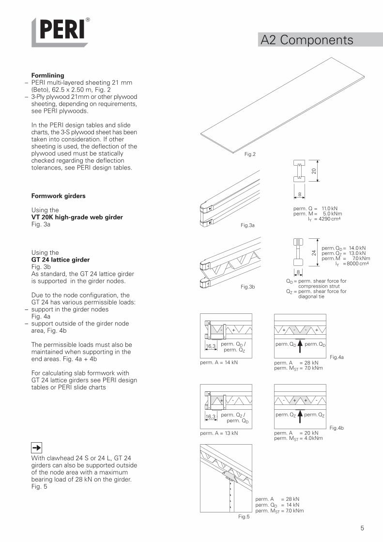
Formlining– PERI multi-layered sheeting 21 mm
(Beto), 62.5 x 2.50 m, Fig. 2– 3-Ply plywood 21mm or other plywood
sheeting, depending on requirements,see PERI plywoods.
In the PERI design tables and slidecharts, the 3-S plywood sheet has beentaken into consideration. If othersheeting is used, the deflection of theplywood used must be staticallychecked regarding the deflectiontolerances, see PERI design tables.
Formwork girders
Using theVT 20K high-grade web girderFig. 3a
Using theGT 24 lattice girderFig. 3bAs standard, the GT 24 lattice girderis supported in the girder nodes.
Due to the node configuration, theGT 24 has various permissible loads:
– support in the girder nodesFig. 4a
– support outside of the girder nodearea, Fig. 4b
The permissible loads must also bemaintained when supporting in theend areas. Fig. 4a + 4b
For calculating slab formwork withGT 24 lattice girders see PERI designtables or PERI slide charts
With clawhead 24 S or 24 L, GT 24girders can also be supported outsideof the node area with a maximumbearing load of 28 kN on the girder.Fig. 5
Fig.5
Fig.4a
Fig.3a
Fig.4b
20
8
- + - ++ -
+ - - + + -
perm. A = 14 kN
perm. A = 13 kN
perm. A = 28 kNperm. MST = 7.0 kNm
perm. A = 20 kNperm. MST = 4.0kNm
perm. A = 28 kNperm. QD = 14 kNperm. MST = 7.0 kNm
Fig.2
perm. Q = 11.0 kNperm. M = 5.0 kNm
lY = 4290 cm4
perm. QD / perm. QZ
perm. QD perm. QD
perm. QZ / perm. QD
perm. QZ perm. QZ
24
8
Fig.3bQD = perm. shear force for
compression strutQZ = perm. shear force for
diagonal tie
perm.QD= 14.0 kNperm.QZ = 13.0 kNperm.M = 7.0 kNm
lY =8000 cm4

6
2a
2b
3a
4
3b
4a 4b
a + b
A2 Components
Slab props
Do not exceed the permissible loadspecifications!For other support systems,individual load specifications mustbe taken into consideration!
All loads resulting from the MULTIFLEXslab formwork must be safelytransferred into the ground or slab.
PERI support systems– steel tube props 4a: PEP– aluminium props 4b:
MULTIPROP (MP), Fig. 6– shoring towers: MP, PERI UP, PD 8,
ST 100For prop loads, see PERI design tables
Supporting heads of formworkProviding stable support for one or twogirders and as intermediate supportfor individual girders.
ExamplesWith self-locking coupling at end ofgirder or on girder joint:
– crosshead 20/24S 2a, alternative:– lowering head 20/24 2b with pins
and cotter pins
For intermediate support:– clawhead 24S 3a– clawhead 16/20S 3b
Fig. 7
Assembly:1. Position head on endplate of prop.
2. Engage self-locking coupling and checkfunctionality, Fig. 8 or without self-locking coupling, secure head with pinsand cotter pins.
3. Position props.The girders can now beaccommodated.
Dismantling:Release coupling or remove pins andtake off head.
Fig.6
Fig.8
40 m
mThe supporting heads offormwork fit all standardslab props with 40 mmhole diameters.
Pay attention to loweringrequirements whenaligning the props.(min. 4 cm).
Fig.7
7
ø 48 - �
120 m
m
A2 Components
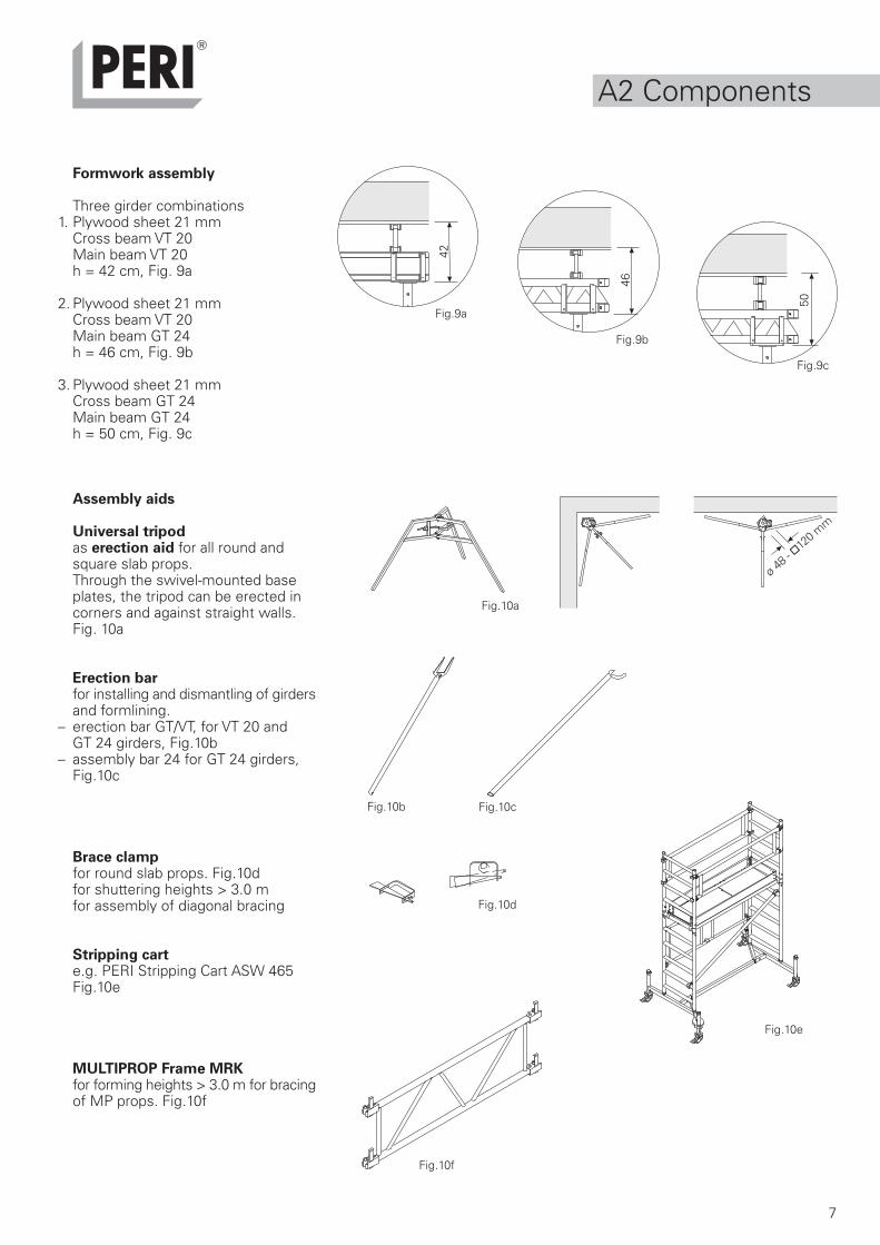
Formwork assembly
Three girder combinations1. Plywood sheet 21 mm
Cross beam VT 20Main beam VT 20h = 42 cm, Fig. 9a
2. Plywood sheet 21 mmCross beam VT 20Main beam GT 24h = 46 cm, Fig. 9b
3. Plywood sheet 21 mmCross beam GT 24Main beam GT 24h = 50 cm, Fig. 9c
Assembly aids
Universal tripodas erection aid for all round andsquare slab props.Through the swivel-mounted baseplates, the tripod can be erected incorners and against straight walls.Fig. 10a
Erection barfor installing and dismantling of girdersand formlining.
– erection bar GT/VT, for VT 20 andGT 24 girders, Fig.10b
– assembly bar 24 for GT 24 girders,Fig.10c
Brace clampfor round slab props. Fig.10dfor shuttering heights > 3.0 mfor assembly of diagonal bracing
Stripping carte.g. PERI Stripping Cart ASW 465Fig.10e
MULTIPROP Frame MRKfor forming heights > 3.0 m for bracingof MP props. Fig.10f
Fig.9b
Fig.9a
Fig.9c
42
46
50
Fig.10a
Fig.10b
Fig.10d
Fig.10e
Fig.10c
Fig.10f

8
1
2b
40 mm
A3 Erection
Attach crosshead or clawhead to prop and engage (withself-locking coupling) Secure other types of support systemsby means of pins and cotter pins:Alternative to crosshead: Lowering Head 20/24 for simpleand easy lowering.
Position crosshead props on flat and load-bearing ground.Secure with tripods (erection aid).
Horizontal loads from the shuttering procedurecan only be transferred for shuttering heights upto approx. 3.0 m.
Shuttering height > 3.0 m with MULTIPROP props:Brace props by means of MRK frames (erection aid).See type test and MULTIPROP assembly instructionsfor more information.
Shuttering height > 3.0 m with steel tube support:e.g. PERI PEP:diagonal bracing must be mounted as an erection aid.
Turn the prop sothat the G-hookcan be operated.
2a
2
9
min.15
VT 20VT 20VT 20 VT 20
A3 Erection
Position crosshead props. Mount main girders frombelow by means of erection bar.One or two main beams can be accommodated in eachcrosshead without any risk of tilting.
Position secondary girder from below by means of erection bar.Align cross beams in such a way so that the plywood sheetingjoints always rest on a cross beam or a pair of girders.Girder overlap: VT 20 min. 15 cm at both ends
GT 24 min.16.3 cm at both ends
Risk of falling!Mount guardrails before shutteringaccording to valid guidelines!
Secure cross beam against tilting.Install plywood sheeting and secure with nails.Level formwork and spray, e.g. with PERI Bio Clean.Caution: risk of slipping!
Mount intermediate props with claw heads on girdersusing prop spacing c.Extend props according to the length. GT 24 girders, see A2.
Risk of tilting!Ensure load effects are safely transferred!**see safety instructions "General Safety information"
The MULTIFLEX slab formwork can be now be usedin accordance with permissible load requirements.Pallets in position on the erection area ready to beused during striking operations
6
3 4
5
c
Main beam spacing bx . Prop spacing c
min.15 min.15min.15 min.15

10
A4 Striking
Observe striking time!
Dismantle intermediate props and store in pallets.In cases of immediate re-use, the heads remain attachedto the props!
Lower all secondary girders by approx. 4 cm*.
Begin lowering and removal of props withlarger prop spans in the centre of the slab.
Dismantle plywood sheets and remaining cross beams– store in pallets.
Plywood must be accurately stacked in order toclean the sheet edges
Dismantle main girders and store in pallets.
* Observe permissible prop loads!If the formwork is not dismantled, it could lead tooverloading the props when concreting the slab forthe next floor.
1
4
2
54
11
A4 Striking
Tip the secondary girders onto their sides and remove frombelow by means of the assembly bar and store in pallets.
Secondary girder located under plywood jointsremain in position.
Dismantle crosshead props and store in pallets.
In cases of immediate re-use, the heads remainattached to the props!
Before the first and any additional use, spray the plywoodsheet edges, e.g. with PERI BIO Clean. This facilitatesshuttering and striking procedures and helps to protectthe sheet.
2a
6 7
4
3
Alternative to No. 2Lower lowering head by means of hammer blow = 4 cm.
Push back wedge to starting position ready fornext use and fix tight with a hammer blow

12
– scaffold components supplied bythe contractors must conform tovalid safety regulations!
– load effects must be safelytransferred!see safety instructions "General Information"
Guardrails *
on slab edges with slab tablesThe edge of the building is secured bymeans of PERI table modules. Fig. 11See also assembly instructions fortable modules.
during casting segmentwith slab edge trestle AWsee B5 for static value
AssemblyThe Stopend Angle 11 can be attachedin girder´s length direction as well asat 90° to the girder:
– 8 wire pins ø 3.1 x 65, (6 pins at front,2 pins at rear, Item. no. 018280)
– with clamp for attaching to the girderor timber
– insert handrail post AW 12 and nailrear end. Fig.12
with Stopend Angle AW, Fig.12a
with panel formwork and StopendAngle AW, Fig.12b
with slab stopend bar 105 andhandrail post HSGP, 13 + 14see B5 for static value. Fig. 13
See PERI construction site equipmentbrochure for additional setting ofstopends
*Guardrails– as a minimum, timber components
must correspond to Sort Class S10according to DIN 4074 and be markedwith a U symbol!
– secure guardrail boards with wire pinsor screws! Fig.12b
Fig.12
Fig.11
Fig.12b
11
11
12
Fig.12a
Fig.13
min
10
max. 14
max
50
13
14
A5 Guardrails andsetting of stopend
13
Static-relevant instructions regarding the use ofslab formwork
Provided on-site assurance can be given that valuesof the slab thickness along with the spacing of thesecondary and main beams do not fall below thosespecified in the tables, and no additional loads areimposed as a result of the formwork being out ofplumb etc., the formwork girders satisfy all thecriteria for classification in Support Scaffold Group III.
Conditions for classifying the supportstructure in Support Scaffold Group I
Classification in Group I is possible for– erection heights of up to 5.00 m– spans of up to 6.00 m– vertical, uniformly distributed loads of up to 8 kN/m2
– uniformly distributed line loads from beams and downstands, and the like, of up to 15 kN/m
Drawings are not required. Proof of stability is onlyrequired if there is insufficient expertise available forassessment purposes.
The loads acting are to be multipliedby the group factor of 1.25
B1 GeneralInstructions
As a rule, the loads acting only have to be increasedby the group factor according to DIN 4421 for thesupport structure, which can mainly be classified inGroup I or II.
Conditions for classifying the supportstructure in Support Scaffold Group II
– proof of stability for all important structuralcomponents and their connections required toprevent collapse. Analyses may be carried outwith the simplifications described in Section 6.4.2.contained in DIN 4421
– drawings: general arrangement drawings whichclearly show the ground plans and sections of theconstruction. Presentation of the most importantdetails is necessary.
The loads acting are to be multipliedby the group factor of 1.15

14
62,562,5 62,5
2,00 m
B2 Calculation ofSlab Formwork(example)
Example with slide chartVT 20/VT 20
Slab thickness: d = 20 cmClear room height: h = 2.80 mMain and cross beams: VT 20Plywood: 21 mm, 62.5 x 250 cm
Pre-selectionPre-selection makes it possible for theuser – subject to the available girderlengths – to more effectively plan theutilisation of the MULTIFLEX withregards to the available prop load-bearing capacity and building geometry.
From:– permissible prop spacing– possible main beam spacing (when
using the GT 24 girder as cross beam,pay attention to the 30 cm nodearrangement)
– available prop load
PlywoodThe 3-S plywood has been consideredin the slide chart.PERI Beto: see table, right.If another type of plywood is used, thecross beam spacing must be adaptedaccordingly, see B5 Plywood Chart.
1. Cross beam spacing aPlywood support, Fig.14(dependent on slab thickness and sizeof plywood sheet used, see B5Plywood Chart)
Cross beam spacing: 62.5 cmSee B5 for static values.
2. Main beam spacing bCross beam support, Fig.15
Max. permissible span for cross beamsaccording to the slide chart: 2.07 mMain beam spacing: 2.00 m(selected, dependent on roomgeometry)
Cross beam Max. slabspacing [cm] thickness [cm]
62.5 22
50 43
Size of plywood62.5 cm x 2.50 m
Fig.15
Fig.14
4 fields
5 fields
Max. slab thickness: PERI Beto
0,60
0,90
1,20
1,50
1,80
2,10
2,40
Loading: according to DIN 4421Deflection: limited to I/500
Basis for calculation is a three-ply sheet, 21 mm,with E = 7500 N/mm2 (saturated)and permissible B = 6.5 N/mm2 (saturated).
0,20
7,1
0,75 0,625 0,50
2,52
2,52
2,52
2,07
1,60
1,22
-
2,68
2,68
2,60
2,07
1,60
1,22
-
2,89
2,89
2,60
2,07
1,60
1,22
- - - -
22,0 22,0 22,0
22,0 22,0 22,0
22,0 22,0 22,0
21,5 22,0 22,0
16,1 17,1 18,5
10,7 11,4 12,3
a
b
c
Slab thickness d [m]Loading q [kN/m2]Permissible main beam spacing b [m]Existing prop load F [kN]Cross beam spacing a [m]
Prop spacing c [m]

15
1,50 m1,50 m1,50 m
H
b
c
a
B2 Calculation ofSlab Formwork(example)
3. Prop spacing cMain beam support, Fig.16Prop spacing: 1.50 m
4. Prop loadSpecification for the slide chart:22.0 kNThrough the selection of the mainbeam spacing of b = 2.00 m, thisresults in a prop load of
to be transferred.
Now select a slab prop (PEP,MULTIPROP) corresponding to theextension length H with permissibleprop load = 21.3 kN.
The respective standards are used forthe support construction.
PERI slide chart for girdercombinations:VT 20 / VT 20GT 24 / VT 20GT 24 / GT 24
Fig.16
Fig.17
Example with PERI design tablesAccording to the selected girdercombination, calculations for theMULTIFLEX slab formwork arecarried out using the tables in B5.Depending on the slab thickness,the selected cross beam spacingand plywood sheet result in themain beam and prop spacings.Fig. 17
F = 22 kN x 2.00 m = 21.3 kN 2.07 m

16
max
. 30
B3 ApplicationExample
Overviewwith edge tablesFig. 18
The basis of the MULTIFLEX is anall-sided horizontal and non-moveablepositioned slab formwork!
This is given with peripheral walls andbeams cast in advance. Otherwise thetransfer of horizontal loads must beensured in accordance with DIN 4421through other measures undertakenon site (e.g. bracing)!
Overview ofstarting bayFig.19
VT 20: min. d 15 cm, max. 30 cmGT 24: min. d 16.3 cm, max. 30 cm
Fig.18
Fig.19

17
B4 Beams
UZ beam systemfor beams up to h = 80 cmconsisting of: UZ Beam Bracket 40 15a
UZ perforated rail 15b
– no formwork ties up to h = 80 cm– cross-sections are to be continuously
formed– girders or timbers can be used as
bottom formwork– side or bottom formwork can also be
formed with PERI TRIO elements– UZ perforated rails can be joined
together for extra-wide beams
Max. beam widthswith side form width b = 10 cm1 x UZ perforated rail 80 = 45 cm2 x UZ perforated rail 80 = 135 cm1 x UZ perforated rail 129 = 95 cmFig. 20See B5 for permissible widths ofinfluence.
Examples1. Side form with one or two 2 GT 24s
(vertical) Fig. 21a
2.Side form with two or three VT 20s(horizontal) Fig. 21b
3.Packing of formwork bottomFig. 21c
Fig.20
Fig.21b
Fig.21c
Fig.21a
15a
15b
b

18
B4 Beams
Stopend Angle AWfor beams up to h = 60 cm
– the stopend angle 11 can be nailed tothe plywood (22 mm) as stopend upto h = 40 cm
– larger widths of influence and heightsare possible with the clamp, see B5
– side formwork can be formed usinghorizontal TRIO, DOMINO orHANDSET elements
– guardrails must be mountedaccording to valid regulations!
– load effects must be safelytransferred!see safety instructions "General Information"
Examples1. Edge beam: stopend nailed to table
module, Fig. 22a
2. Beam with Domino elements,Fig. 22b
3. Stopend angle with clamp 11a,Fig. 22c
AssemblySee A5, stopend angle AW
Used plywood sheets can be usedfor the working areas.
Fig.22b
Fig.22a
11
Fig.22c
11a

19

20
B5 Design tables
Plywood
Type ofplywood
Fin Ply
Fin Ply, Maxi
Fin Ply, USA
Fin Ply
PERI Birch
PERI Birch, USA
Combi Mirror
PERI Beto
PERI Beto, USA
PERI Beto
PERI Spruce
As-Ply
3-Ply Plywood
3-Ply Plywood
Lake Pine
Arauco Pine
FinNa-Ply
Thickness [mm]
21
20
19 / 3/4”
18
21
19 / 3/4”
21
21
19 / 3/4”
18
21
21
27
21
20,5
21
21
Veneers
Birch
Birch
Birch
Birch
Birch
Birch
Birch/Conifer Ply.
Birch/Conifer Ply.
Birch/Conifer Ply.
Birch/Conifer Ply.
Conifer Plywood
Plywood
Spruce
Spruce
Plywood
Pine
Conifer Plywood
E-modulus [N/mm2]
parallel/crosswise
8560/6610
7500/5760
6180/6880
8730/6440
8560/6610
9170/7060
8560/5060
6610/6560
6610/7140
6680/6500
5240/6370
1)
8000/1070
8000/1070
1)
1)
7910/3710
perm. [N/mm2]
parallel/crosswise
15.0/12.4
13.0/10.5
12.0/11.5
15.3/12.2
15.0/12.4
15.7/13.6
14.9/6.8
11.2/8.5
11.3/10.6
10.2/8.7
6.7/7.0
1)
4.9/1.5
5.9/1.3
1)
1)
8.0/5.0
1) No information possible because of large differences.
The static/mechanical values given in the tables refer, according toinformation from the manufacturers, to a moisture content of 15%.But GSV stipulate the values of moisture content as 20%.The values for the Modulus of Elasticity are therefore to bereduced by a factor of 0.9167 and the values for the permissibletension by a factor of 0.875.
The fibres of the face veneer span in the directionof the first length shown for the plywood size.
Solid timber
With a timber moisture content of 20% only the permissible tensionaccording to DIN 1052 is to be reduced by 0.833.
Softwood, Sorting Class S10
E-modulus [N/mm2]
parallel/crosswise
10000
perm. [N/mm2]
parallel/crosswise
10

21
L L L L L L L
B5 Design tables
21 mm Plywood
The modulus of elasticity and the permissibletension is based on the grade and moisturecontent of the plywood (see page 20).
0.0068 · q · L4
Maximum deflection f = ––––––––––––––E · I
Maximum Moment M = 0.1071 · q · L2
(valid for at least 3 bays)
10 20 300 40 50 60 70 80 90 100 Concretepressure q[kN/m2]
25 cm
30 cm
35 cm
45 c
m
75 c
m
50 c
m
55 c
m
65 c
m
Def
lect
ion
f [m
m]
E =
300
0 N
/mm
2
E =
400
0 N
/mm
2
E =
500
0 N
/mm
2
E =
600
0 N
/mm
2
E =
700
0 N
/mm
2
E =
800
0 N
/mm
2
SPAN L
4.0
3.5
3.0
2.5
2.0
1.5
1.0
0.5
0.0
f f
4.6
4.0
3.4
2.9
2.3
1.7
1.1
0.6
0.0
5.3
4.7
4.0
3.3
2.7
2.0
1.3
0.7
0.0
6.4
5.6
4.8
4.0
3.2
2.4
1.6
0.8
0.0
8.0
7.0
6.0
5.0
4.0
3.0
2.0
1.0
0.0
10.7
9.3
8.0
6.7
5.3
4.0
2.7
1.3
0.0
Wall formwork
Slab formwork Slab Thickness d [cm]20 400 60 80 10010 30 50 70 90
60 c
m
70 c
m
40 cm
=
13N
/mm 2
=11
N/m
m 2
=
9N
/mm 2
=
7N
/mm 2
=5
N/m
m2
22
B5 Design tables
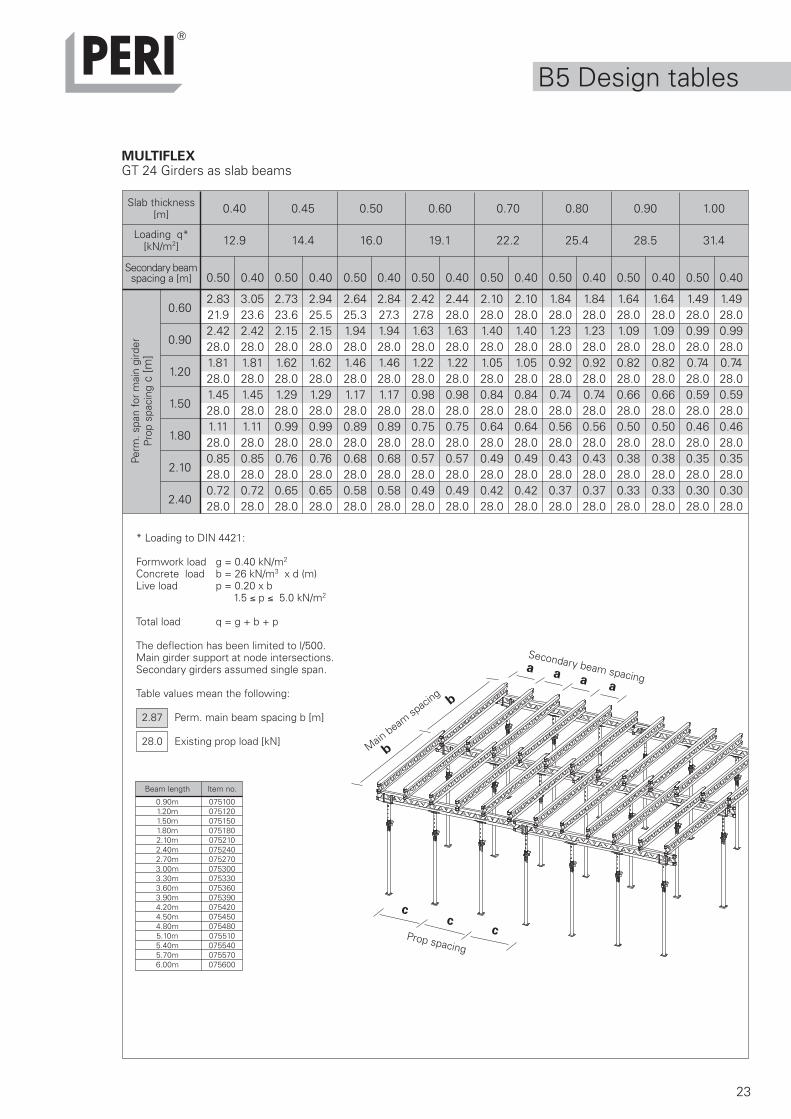
MULTIFLEXGT 24 Girders as slab beams
0.22 0.24 0.26 0.28 0.30 0.35
7.6 8.1 8.7 9.2 9.8 11.3
0.75 0.625 0.50 0.625 0.50 0.40 0.625 0.50 0.40 0.625 0.50 0.40 0.625 0.50 0.40 0.50 0.40
2.99 3.18 3.42 3.09 3.33 3.59 3.02 3.25 3.50 2.95 3.17 3.42 2.88 3.11 3.35 2.96 3.1913.7 14.5 15.7 15.1 16.3 17.5 15.7 16.9 18.2 16.2 17.5 18.8 16.9 18.2 19.6 20.1 21.62.99 3.18 3.42 3.09 3.33 3.59 3.02 3.25 3.50 2.95 3.17 3.39 2.88 3.11 3.19 2.75 2.7520.5 21.8 23.5 22.7 24.4 26.3 23.5 25.3 27.3 24.3 26.2 28.0 25.3 27.3 28.0 28.0 28.02.99 3.06 3.06 2.87 2.87 2.87 2.69 2.69 2.69 2.54 2.54 2.54 2.39 2.39 2.39 2.06 2.0627.4 28.0 28.0 28.0 28.0 28.0 28.0 28.0 28.0 28.0 28.0 28.0 28.0 28.0 28.0 28.0 28.02.45 2.45 2.45 2.29 2.29 2.29 2.16 2.16 2.16 2.03 2.03 2.03 1.91 1.91 1.91 1.65 1.6528.0 28.0 28.0 28.0 28.0 28.0 28.0 28.0 28.0 28.0 28.0 28.0 28.0 28.0 28.0 28.0 28.01.88 1.88 1.88 1.76 1.76 1.76 1.65 1.65 1.65 1.56 1.56 1.56 1.47 1.47 1.47 1.26 1.2628.0 28.0 28.0 28.0 28.0 28.0 28.0 28.0 28.0 28.0 28.0 28.0 28.0 28.0 28.0 28.0 28.01.43 1.43 1.43 1.34 1.34 1.34 1.26 1.26 1.26 1.19 1.19 1.19 1.12 1.12 1.12 0.96 0.9628.0 28.0 28.0 28.0 28.0 28.0 28.0 28.0 28.0 28.0 28.0 28.0 28.0 28.0 28.0 28.0 28.01.22 1.22 1.22 1.15 1.15 1.15 1.08 1.08 1.08 1.02 1.02 1.02 0.96 0.96 0.96 0.82 0.8228.0 28.0 28.0 28.0 28.0 28.0 28.0 28.0 28.0 28.0 28.0 28.0 28.0 28.0 28.0 28.0 28.0
0.60
0.90
1.20
1.50
1.80
2.10
2.40
0.10 0.12 0.14 0.16 0.18 0.20
4.5 5.0 5.5 6.1 6.6 7.1
0.75 0.625 0.50 0.75 0.625 0.50 0.75 0.625 0.50 0.75 0.625 0.50 0.75 0.625 0.50 0.75 0.625 0.50
3.79 4.03 4.34 3.60 3.82 4.12 3.44 3.65 3.93 3.30 3.51 3.78 3.18 3.38 3.64 3.08 3.27 3.5310.2 10.9 11.7 10.8 11.5 12.4 11.4 12.1 13.1 12.0 12.7 13.7 12.6 13.4 14.4 13.1 13.9 15.03.79 4.03 4.34 3.60 3.82 4.12 3.44 3.65 3.93 3.30 3.51 3.78 3.18 3.38 3.64 3.08 3.27 3.5315.4 16.3 17.6 16.3 17.3 18.6 17.1 18.2 19.6 18.0 19.1 20.6 18.9 20.0 21.6 19.7 20.9 22.53.79 4.03 4.34 3.60 3.82 4.12 3.44 3.65 3.93 3.30 3.51 3.78 3.18 3.38 3.55 3.08 3.27 3.2920.5 21.8 23.5 21.7 23.0 24.8 22.8 24.3 26.1 24.0 25.5 27.5 25.1 26.7 28.0 26.3 27.9 28.03.79 4.03 4.15 3.60 3.72 3.72 3.37 3.37 3.37 3.08 3.08 3.08 2.84 2.84 2.84 2.63 2.63 2.6325.6 27.2 28.0 27.1 28.0 28.0 28.0 28.0 28.0 28.0 28.0 28.0 28.0 28.0 28.0 28.0 28.0 28.03.18 3.18 3.18 2.85 2.85 2.85 2.58 2.58 2.58 2.36 2.36 2.36 2.18 2.18 2.18 2.02 2.02 2.0228.0 28.0 28.0 28.0 28.0 28.0 28.0 28.0 28.0 28.0 28.0 28.0 28.0 28.0 28.0 28.0 28.0 28.02.43 2.43 2.43 2.17 2.17 2.17 1.97 1.97 1.97 1.80 1.80 1.80 1.66 1.66 1.66 1.54 1.54 1.5428.0 28.0 28.0 28.0 28.0 28.0 28.0 28.0 28.0 28.0 28.0 28.0 28.0 28.0 28.0 28.0 28.0 28.02.07 2.07 2.07 1.86 1.86 1.86 1.68 1.68 1.68 1.54 1.54 1.54 1.42 1.42 1.42 1.31 1.31 1.3128.0 28.0 28.0 28.0 28.0 28.0 28.0 28.0 28.0 28.0 28.0 28.0 28.0 28.0 28.0 28.0 28.0 28.0
Perm
. spa
n fo
r m
ain
gird
erPr
op s
paci
ng c
[m]
Slab thickness[m]
Loading q*[kN/m2]
Secondary beamspacing a [m]
0.60
0.90
1.20
1.50
1.80
2.10
2.40
Perm
. spa
n fo
r m
ain
gird
erPr
op s
paci
ng c
[m]
Slab thickness[m]
Loading q*[kN/m2]
Secondary beamspacing a [m]
23
a aa
b
b
a
cc
c
B5 Design tables
MULTIFLEXGT 24 Girders as slab beams
0.40 0.45 0.50 0.60 0.70 0.80 0.90 1.00
12.9 14.4 16.0 19.1 22.2 25.4 28.5 31.4
0.50 0.40 0.50 0.40 0.50 0.40 0.50 0.40 0.50 0.40 0.50 0.40 0.50 0.40 0.50 0.40
2.83 3.05 2.73 2.94 2.64 2.84 2.42 2.44 2.10 2.10 1.84 1.84 1.64 1.64 1.49 1.4921.9 23.6 23.6 25.5 25.3 27.3 27.8 28.0 28.0 28.0 28.0 28.0 28.0 28.0 28.0 28.02.42 2.42 2.15 2.15 1.94 1.94 1.63 1.63 1.40 1.40 1.23 1.23 1.09 1.09 0.99 0.9928.0 28.0 28.0 28.0 28.0 28.0 28.0 28.0 28.0 28.0 28.0 28.0 28.0 28.0 28.0 28.01.81 1.81 1.62 1.62 1.46 1.46 1.22 1.22 1.05 1.05 0.92 0.92 0.82 0.82 0.74 0.7428.0 28.0 28.0 28.0 28.0 28.0 28.0 28.0 28.0 28.0 28.0 28.0 28.0 28.0 28.0 28.01.45 1.45 1.29 1.29 1.17 1.17 0.98 0.98 0.84 0.84 0.74 0.74 0.66 0.66 0.59 0.5928.0 28.0 28.0 28.0 28.0 28.0 28.0 28.0 28.0 28.0 28.0 28.0 28.0 28.0 28.0 28.01.11 1.11 0.99 0.99 0.89 0.89 0.75 0.75 0.64 0.64 0.56 0.56 0.50 0.50 0.46 0.4628.0 28.0 28.0 28.0 28.0 28.0 28.0 28.0 28.0 28.0 28.0 28.0 28.0 28.0 28.0 28.00.85 0.85 0.76 0.76 0.68 0.68 0.57 0.57 0.49 0.49 0.43 0.43 0.38 0.38 0.35 0.3528.0 28.0 28.0 28.0 28.0 28.0 28.0 28.0 28.0 28.0 28.0 28.0 28.0 28.0 28.0 28.00.72 0.72 0.65 0.65 0.58 0.58 0.49 0.49 0.42 0.42 0.37 0.37 0.33 0.33 0.30 0.3028.0 28.0 28.0 28.0 28.0 28.0 28.0 28.0 28.0 28.0 28.0 28.0 28.0 28.0 28.0 28.0
0.60
0.90
1.20
1.50
1.80
2.10
2.40
Main beam
spac
ing
Prop spacing
Secondary beam spacing
Beam length Item no.
0.90m 0751001.20m 0751201.50m 0751501.80m 0751802.10m 0752102.40m 0752402.70m 0752703.00m 0753003.30m 0753303.60m 0753603.90m 0753904.20m 0754204.50m 0754504.80m 0754805.10m 0755105.40m 0755405.70m 0755706.00m 075600
* Loading to DIN 4421:
Formwork load g = 0.40 kN/m2
Concrete load b = 26 kN/m3 x d (m)Live load p = 0.20 x b
1.5 p 5.0 kN/m2
Total load q = g + b + p
The deflection has been limited to l/500.Main girder support at node intersections.Secondary girders assumed single span.
Table values mean the following:
2.87 Perm. main beam spacing b [m]
28.0 Existing prop load [kN]
Perm
. spa
n fo
r m
ain
gird
erPr
op s
paci
ng c
[m]
Slab thickness[m]
Loading q*[kN/m2]
Secondary beamspacing a [m]
24
B5 Design tables
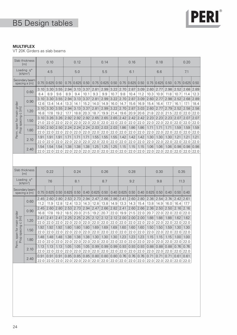
MULTIFLEXVT 20K Girders as slab beams
0.22 0.24 0.26 0.28 0.30 0.35
7.6 8.1 8.7 9.2 9.8 11.3
0.75 0.625 0.50 0.625 0.50 0.40 0.625 0.50 0.40 0.625 0.50 0.40 0.625 0.50 0.40 0.50 0.40
2.45 2.60 2.80 2.53 2.73 2.94 2.47 2.66 2.86 2.41 2.60 2.80 2.36 2.54 2.74 2.42 2.6111.2 11.9 12.8 12.4 13.3 14.3 12.8 13.8 14.9 13.3 14.3 15.4 13.8 14.9 16.0 16.4 17.72.45 2.60 2.80 2.53 2.73 2.94 2.47 2.66 2.82 2.41 2.60 2.66 2.36 2.50 2.50 2.16 2.1616.8 17.8 19.2 18.5 20.0 21.5 19.2 20.7 22.0 19.9 21.5 22.0 20.7 22.0 22.0 22.0 22.02.41 2.41 2.41 2.25 2.25 2.25 2.12 2.12 2.12 2.00 2.00 2.00 1.88 1.88 1.88 1.62 1.6222.0 22.0 22.0 22.0 22.0 22.0 22.0 22.0 22.0 22.0 22.0 22.0 22.0 22.0 22.0 22.0 22.01.92 1.92 1.92 1.80 1.80 1.80 1.69 1.69 1.69 1.60 1.60 1.60 1.50 1.50 1.59 1.30 1.3022.0 22.0 22.0 22.0 22.0 22.0 22.0 22.0 22.0 22.0 22.0 22.0 22.0 22.0 22.0 22.0 22.01.48 1.48 1.48 1.38 1.38 1.38 1.30 1.30 1.30 1.23 1.23 1.23 1.15 1.15 1.15 1.00 1.0022.0 22.0 22.0 22.0 22.0 22.0 22.0 22.0 22.0 22.0 22.0 22.0 22.0 22.0 22.0 22.0 22.01.13 1.13 1.13 1.05 1.05 1.05 0.99 0.99 0.99 0.93 0.93 0.93 0.88 0.88 0.88 0.76 0.7622.0 22.0 22.0 22.0 22.0 22.0 22.0 22.0 22.0 22.0 22.0 22.0 22.0 22.0 22.0 22.0 22.00.91 0.91 0.91 0.85 0.85 0.85 0.80 0.80 0.80 0.76 0.76 0.76 0.71 0.71 0.71 0.61 0.6122.0 22.0 22.0 22.0 22.0 22.0 22.0 22.0 22.0 22.0 22.0 22.0 22.0 22.0 22.0 22.0 22.0
0.60
0.90
1.20
1.50
1.80
2.10
2.40
0.10 0.12 0.14 0.16 0.18 0.20
4.5 5.0 5.5 6.1 6.6 7.1
0.75 0.625 0.50 0.75 0.625 0.50 0.75 0.625 0.50 0.75 0.625 0.50 0.75 0.625 0.50 0.75 0.625 0.50
3.10 3.30 3.55 2.94 3.13 3.37 2.81 2.99 3.22 2.70 2.87 3.09 2.60 2.77 2.98 2.52 2.68 2.898.4 8.9 9.6 8.9 9.4 10.1 9.3 9.9 10.7 9.8 10.4 11.2 10.3 10.9 11.8 10.7 11.4 12.33.10 3.30 3.55 2.94 3.13 3.37 2.81 2.99 3.22 2.70 2.87 3.09 2.60 2.77 2.98 2.52 2.68 2.8912.6 13.4 14.4 13.3 14.1 15.2 14.0 14.9 16.0 14.7 15.6 16.9 15.4 16.4 17.7 16.1 17.1 18.43.10 3.30 3.55 2.94 3.13 3.37 2.81 2.99 3.22 2.70 2.87 3.03 2.60 2.77 2.79 2.52 2.58 2.5816.8 17.8 19.2 17.7 18.8 20.3 18.7 19.9 21.4 19.6 20.9 20.6 21.8 22.0 21.5 22.0 22.0 22.03.10 3.26 3.26 2.92 2.92 2.92 2.65 2.65 2.65 2.42 2.42 2.42 2.23 2.23 2.23 2.07 2.07 2.0721.0 22.0 22.0 22.0 22.0 22.0 22.0 22.0 22.0 22.0 22.0 22.0 22.0 22.0 22.0 22.0 22.0 22.02.50 2.50 2.50 2.24 2.24 2.24 2.03 2.03 2.03 1.86 1.86 1.86 1.71 1.71 1.71 1.59 1.59 1.5922.0 22.0 22.0 22.0 22.0 22.0 22.0 22.0 22.0 22.0 22.0 22.0 22.0 22.0 22.0 22.0 22.0 22.01.91 1.91 1.91 1.71 1.71 1.71 1.55 1.55 1.55 1.42 1.42 1.42 1.30 1.30 1.30 1.21 1.21 1.2122.0 22.0 22.0 22.0 22.0 22.0 22.0 22.0 22.0 22.0 22.0 22.0 22.0 22.0 22.0 22.0 22.0 22.01.54 1.54 1.54 1.38 1.38 1.38 1.25 1.25 1.25 1.15 1.15 1.15 1.06 1.06 1.06 0.98 0.98 0.9822.0 22.0 22.0 22.0 22.0 22.0 22.0 22.0 22.0 22.0 22.0 22.0 22.0 22.0 22.0 22.0 22.0 22.0
0.60
0.90
1.20
1.50
1.80
2.10
2.40
Perm
. spa
n fo
r m
ain
gird
erPr
op s
paci
ng c
[m]
Slab thickness[m]
Loading q*[kN/m2]
Secondary beamspacing a [m]
Perm
. spa
n fo
r m
ain
gird
erPr
op s
paci
ng c
[m]
Slab thickness[m]
Loading q*[kN/m2]
Secondary beamspacing a [m]
25
a
b
c
b
a aa
cc
B5 Design tables
MULTIFLEXVT 20K Girders as slab beams
0.40 0.45 0.50 0.60 0.70 0.80 0.90 1.00
12.9 14.4 16.0 19.1 22.2 25.4 28.5 31.4
0.50 0.40 0.50 0.40 0.50 0.40 0.50 0.40 0.50 0.40 0.50 0.40 0.50 0.40 0.50 0.40
2.32 2.50 2.23 2.40 2.16 2.29 1.92 1.92 1.65 1.65 1.45 1.45 1.29 1.29 1.17 1.1717.9 19.3 19.3 20.8 20.7 22.0 22.0 22.0 22.0 22.0 22.0 22.0 22.0 22.0 22.0 22.01.90 1.90 1.69 1.69 1.53 1.53 1.28 1.28 1.10 1.10 0.96 0.96 0.86 0.86 0.78 0.7822.0 22.0 22.0 22.0 22.0 22.0 22.0 22.0 22.0 22.0 22.0 22.0 22.0 22.0 22.0 22.01.42 1.42 1.27 1.27 1.15 1.15 0.96 0.96 0.82 0.82 0.72 0.72 0.64 0.64 0.58 0.5822.0 22.0 22.0 22.0 22.0 22.0 22.0 22.0 22.0 22.0 22.0 22.0 22.0 22.0 22.0 22.01.14 1.14 1.02 1.02 0.92 0.92 0.77 0.77 0.66 0.66 0.58 0.58 0.51 0.51 0.47 0.4722.0 22.0 22.0 22.0 22.0 22.0 22.0 22.0 22.0 22.0 22.0 22.0 22.0 22.0 22.0 22.00.87 0.87 0.78 0.78 0.70 0.70 0.59 0.59 0.51 0.51 0.44 0.44 0.40 0.40 0.36 0.3622.0 22.0 22.0 22.0 22.0 22.0 22.0 22.0 22.0 22.0 22.0 22.0 22.0 22.0 22.0 22.00.67 0.67 0.59 0.59 0.54 0.54 0.45 0.45 0.39 0.39 0.34 0.34 0.30 0.3022.0 22.0 22.0 22.0 22.0 22.0 22.0 22.0 22.0 22.0 22.0 22.0 22.0 22.00.54 0.54 0.48 0.48 0.43 0.43 0.36 0.36 0.31 0.3122.0 22.0 22.0 22.0 22.0 22.0 22.0 22.0 22.0 22.0
0.60
0.90
1.20
1.50
1.80
2.10
2.40
* Loading to DIN 4421:
Formwork load g = 0.40 kN/m2
Concrete load b = 26 kN/m3 x d (m)Live load p = 0.20 x b
1.5 p 5.0 kN/m2
Total load q = g + b + p
The deflection has been limited to l/500.Secondary girders assumed single span.
Table values mean the following:
2.25 Perm. main beam spacing b [m]
22.0 Existing prop load [kN]
Secondary beam spacing
Main beam
spac
ing
Prop spacing
Beam length Item no.
1.45m 0749902.15m 0749052.45m 0749102.65m 0748902.90m 0749203.30m 0749303.60m 0749403.90m 0749504.50m 0749604.90m 0749705.90m 074980
Perm
. spa
n fo
r m
ain
gird
erPr
op s
paci
ng c
[m]
Slab thickness[m]
Loading q*[kN/m2]
Secondary beamspacing a [m]
26
a
b
c
ba a
a
c
B5 Design tables
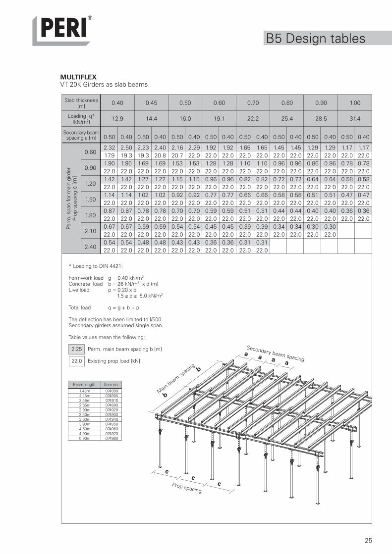
MULTIFLEXSecondary Girder: GT 24 / Main Girder: 2x GT 24
* Load to DIN 4421:
Dead load g = 0.40 kN/m2
Concrete load b = 26 kN/m3 x d (m)Live load p = 0.20 x b
1.5 p 5.0 kN/m2
Total load q = g + b + p
The deflection has been limited to 1/500.Main girder support at node intersections.Secondary girders assumed single span.
Table values mean the following:
3.17 perm. spacing of main girders [m]
56.0 actual prop load [kN]
One GT 24 is sufficient as main girderwhen prop loads < 28.0 kN
0.22 0.24 0.25 0.26 0.28
7.6 8.1 8.4 8.7 9.2
0.75 0.625 0.50 0.625 0.50 0.40 0.625 0.50 0.40 0.625 0.50 0.40 0.625 0.50 0.40
2.99 3.18 3.42 3.09 3.33 3.59 3.06 3.29 3.55 3.02 3.25 3.50 2.95 3.17 3.4213.6 14.5 15.6 15.0 16.2 17.4 15.4 16.6 17.9 15.8 17.0 18.3 16.3 17.5 18.92.99 3.18 3.42 3.09 3.33 3.59 3.06 3.29 3.55 3.02 3.25 3.50 2.95 3.17 3.4220.5 21.8 23.4 22.5 24.3 26.2 23.1 24.9 26.8 23.6 25.4 27.4 24.4 26.2 28.32.99 3.18 3.42 3.09 3.33 3.59 3.06 3.29 3.55 3.02 3.25 3.50 2.95 3.17 3.4227.3 29.0 31.2 30.0 32.4 34.9 30.8 33.2 35.8 31.5 33.9 36.5 32.6 35.0 37.82.99 3.18 3.42 3.09 3.33 3.59 3.06 3.29 3.55 3.02 3.25 3.50 2.95 3.17 3.4234.1 36.3 39.0 37.5 40.5 43.6 38.6 41.5 44.7 39.4 42.4 45.7 40.7 43.7 47.22.99 3.18 3.42 3.09 3.33 3.59 3.06 3.29 3.55 3.02 3.25 3.50 2.95 3.17 3.3840.9 43.5 46.8 45.1 48.6 52.3 46.3 49.7 53.7 47.3 50.9 54.8 48.9 52.5 56.0
0.60
0.90
1.20
1.50
1.80
0.30 0.35 0.40 0.50 0.60 0.70 0.80 0.90 1.00
9.8 11.3 12.9 16.0 19.1 22.2 25.4 28.5 31.4
0.625 0.50 0.40 0.50 0.40 0.50 0.40 0.50 0.40 0.50 0.40 0.40 0.40 0.40 0.40
2.88 3.11 3.35 2.97 3.21 2.83 3.05 2.64 2.84 2.42 2.68 2.51 2.35 2.22 2.0716.9 18.3 19.7 20.1 21.8 21.9 23.6 25.3 27.3 27.7 30.7 33.4 35.8 38.0 39.02.88 3.11 3.35 2.97 3.21 2.83 3.05 2.64 2.84 2.42 2.68 2.51 2.35 2.18 1.9825.4 27.4 29.5 30.2 32.6 32.9 35.4 38.0 40.9 41.6 46.1 50.1 53.7 56.0 56.02.88 3.11 3.35 2.97 3.21 2.83 3.05 2.64 2.84 2.42 2.44 2.10 1.84 1.64 1.4933.9 36.6 39.4 40.3 43.5 43.8 47.2 50.7 54.5 55.5 56.0 56.0 56.0 56.0 56.02.88 3.11 3.35 2.97 3.21 2.83 2.89 2.33 2.33 1.95 1.95 1.68 1.47 1.31 1.1942.3 45.7 49.2 50.3 54.4 54.8 56.0 56.0 56.0 56.0 56.0 56.0 56.0 56.0 56.02.88 3.11 3.17 2.75 2.75 2.41 2.41 1.94 1.94 1.63 1.63 1.40 1.22 1.09 0.9950.8 54.9 56.0 56.0 56.0 56.0 56.0 56.0 56.0 56.0 56.0 56.0 56.0 56.0 56.0
Secondary girder spacing
Main girder spacing
Propspacing
0.60
0.90
1.20
1.50
1.80
Perm
. spa
n fo
r m
ain
gird
erPr
op s
paci
ng c
[m]
Slab thickness[m]
Loading q*[kN/m2]
Secondary beamspacing a [m]
Perm
. spa
n fo
r m
ain
gird
erPr
op s
paci
ng c
[m]
Slab thickness[m]
Loading q*[kN/m2]
Secondary beamspacing a [m]
27
a
b
c
ba a
c
B5 Design tables
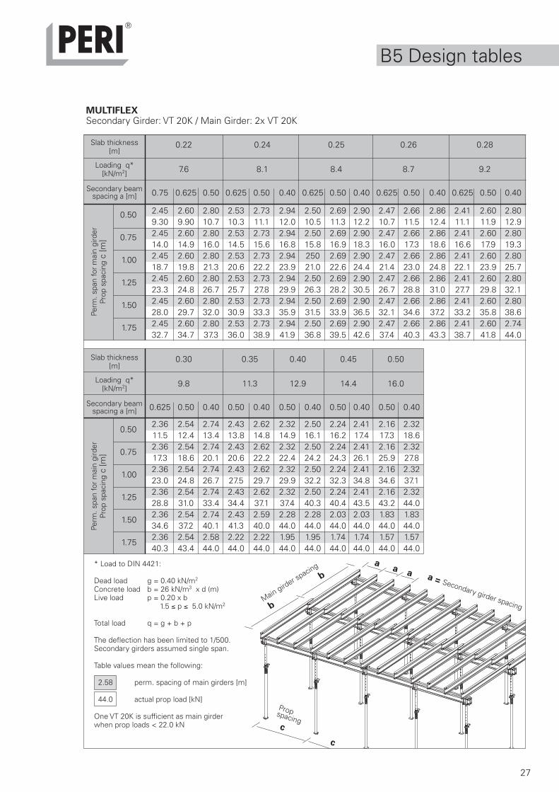
MULTIFLEXSecondary Girder: VT 20K / Main Girder: 2x VT 20K
a = Secondary girder spacingMain girder spacing
Propspacing
0.22 0.24 0.25 0.26 0.28
7.6 8.1 8.4 8.7 9.2
0.75 0.625 0.50 0.625 0.50 0.40 0.625 0.50 0.40 0.625 0.50 0.40 0.625 0.50 0.40
2.45 2.60 2.80 2.53 2.73 2.94 2.50 2.69 2.90 2.47 2.66 2.86 2.41 2.60 2.809.30 9.90 10.7 10.3 11.1 12.0 10.5 11.3 12.2 10.7 11.5 12.4 11.1 11.9 12.92.45 2.60 2.80 2.53 2.73 2.94 2.50 2.69 2.90 2.47 2.66 2.86 2.41 2.60 2.8014.0 14.9 16.0 14.5 15.6 16.8 15.8 16.9 18.3 16.0 17.3 18.6 16.6 17.9 19.32.45 2.60 2.80 2.53 2.73 2.94 250 2.69 2.90 2.47 2.66 2.86 2.41 2.60 2.8018.7 19.8 21.3 20.6 22.2 23.9 21.0 22.6 24.4 21.4 23.0 24.8 22.1 23.9 25.72.45 2.60 2.80 2.53 2.73 2.94 2.50 2.69 2.90 2.47 2.66 2.86 2.41 2.60 2.8023.3 24.8 26.7 25.7 27.8 29.9 26.3 28.2 30.5 26.7 28.8 31.0 27.7 29.8 32.12.45 2.60 2.80 2.53 2.73 2.94 2.50 2.69 2.90 2.47 2.66 2.86 2.41 2.60 2.8028.0 29.7 32.0 30.9 33.3 35.9 31.5 33.9 36.5 32.1 34.6 37.2 33.2 35.8 38.62.45 2.60 2.80 2.53 2.73 2.94 2.50 2.69 2.90 2.47 2.66 2.86 2.41 2.60 2.7432.7 34.7 37.3 36.0 38.9 41.9 36.8 39.5 42.6 37.4 40.3 43.3 38.7 41.8 44.0
0.50
0.75
1.00
1.25
1.50
1.75
0.30 0.35 0.40 0.45 0.50
9.8 11.3 12.9 14.4 16.0
0.625 0.50 0.40 0.50 0.40 0.50 0.40 0.50 0.40 0.50 0.40
2.36 2.54 2.74 2.43 2.62 2.32 2.50 2.24 2.41 2.16 2.3211.5 12.4 13.4 13.8 14.8 14.9 16.1 16.2 17.4 17.3 18.62.36 2.54 2.74 2.43 2.62 2.32 2.50 2.24 2.41 2.16 2.3217.3 18.6 20.1 20.6 22.2 22.4 24.2 24.3 26.1 25.9 27.82.36 2.54 2.74 2.43 2.62 2.32 2.50 2.24 2.41 2.16 2.3223.0 24.8 26.7 27.5 29.7 29.9 32.2 32.3 34.8 34.6 37.12.36 2.54 2.74 2.43 2.62 2.32 2.50 2.24 2.41 2.16 2.3228.8 31.0 33.4 34.4 37.1 37.4 40.3 40.4 43.5 43.2 44.02.36 2.54 2.74 2.43 2.59 2.28 2.28 2.03 2.03 1.83 1.8334.6 37.2 40.1 41.3 40.0 44.0 44.0 44.0 44.0 44.0 44.02.36 2.54 2.58 2.22 2.22 1.95 1.95 1.74 1.74 1.57 1.5740.3 43.4 44.0 44.0 44.0 44.0 44.0 44.0 44.0 44.0 44.0
* Load to DIN 4421:
Dead load g = 0.40 kN/m2
Concrete load b = 26 kN/m3 x d (m)Live load p = 0.20 x b
1.5 p 5.0 kN/m2
Total load q = g + b + p
The deflection has been limited to 1/500.Secondary girders assumed single span.
Table values mean the following:
2.58 perm. spacing of main girders [m]
44.0 actual prop load [kN]
One VT 20K is sufficient as main girderwhen prop loads < 22.0 kN
0.50
0.75
1.00
1.25
1.50
1.75
Perm
. spa
n fo
r m
ain
gird
erPr
op s
paci
ng c
[m]
Slab thickness[m]
Loading q*[kN/m2]
Secondary beamspacing a [m]
Perm
. spa
n fo
r m
ain
gird
erPr
op s
paci
ng c
[m]
Slab thickness[m]
Loading q*[kN/m2]
Secondary beamspacing a [m]
28
f
Z
B5 Design tables
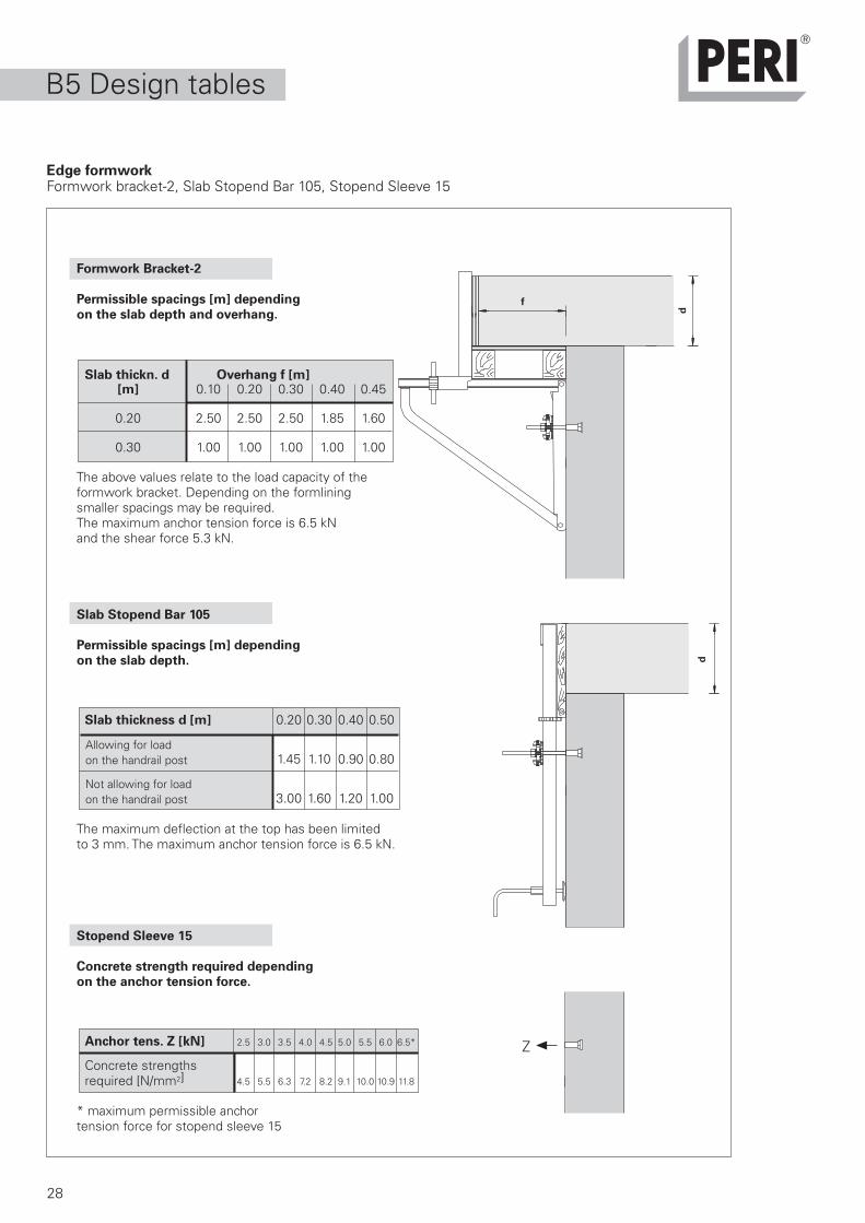
Formwork Bracket-2
Permissible spacings [m] depending
on the slab depth and overhang.
Slab thickn. d Overhang f [m][m] 0.10 0.20 0.30 0.40 0.45
0.20 2.50 2.50 2.50 1.85 1.60
0.30 1.00 1.00 1.00 1.00 1.00
The above values relate to the load capacity of theformwork bracket. Depending on the formliningsmaller spacings may be required.The maximum anchor tension force is 6.5 kNand the shear force 5.3 kN.
Slab Stopend Bar 105
Permissible spacings [m] depending
on the slab depth.
Slab thickness d [m] 0.20 0.30 0.40 0.50
1.45 1.10 0.90 0.80
3.00 1.60 1.20 1.00
The maximum deflection at the top has been limitedto 3 mm. The maximum anchor tension force is 6.5 kN.
Stopend Sleeve 15
Concrete strength required depending
on the anchor tension force.
Anchor tens. Z [kN] 2.5 3.0 3.5 4.0 4.5 5.0 5.5 6.0 6.5*
4.5 5.5 6.3 7.2 8.2 9.1 10.0 10.9 11.8
* maximum permissible anchortension force for stopend sleeve 15
Concrete strengthsrequired [N/mm2]
Allowing for loadon the handrail post
Not allowing for loadon the handrail post
d
d
Edge formworkFormwork bracket-2, Slab Stopend Bar 105, Stopend Sleeve 15

29
30
1x GT 24 2x VT 20 1x GT 24 2x VT 20 2x GT 24 2x VT 20 2x GT 24 2x VT 20 2x GT 24 3x VT 20 2x GT 24 3x VT 20
B5 Design tables
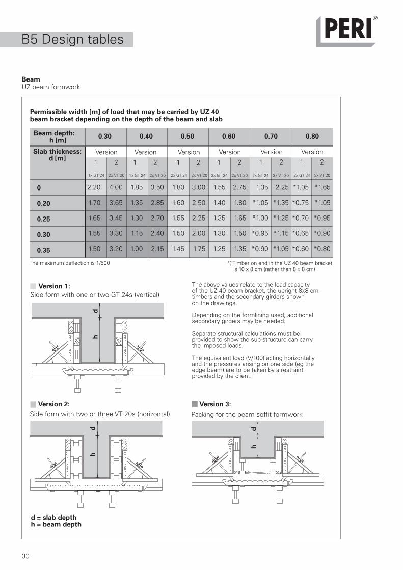
BeamUZ beam formwork
Permissible width [m] of load that may be carried by UZ 40beam bracket depending on the depth of the beam and slab
Beam depth:h [m]
0.30 0.40 0.50 0.60 0.70 0.80
Slab thickness:d [m]
0
0.20
0.25
0.30
0.35
The above values relate to the load capacityof the UZ 40 beam bracket, the upright 8x8 cmtimbers and the secondary girders shownon the drawings.
Depending on the formlining used, additionalsecondary girders may be needed.
Separate structural calculations must beprovided to show the sub-structure can carrythe imposed loads.
The equivalent load (V/100) acting horizontallyand the pressures arising on one side (eg theedge beam) are to be taken by a restraintprovided by the client.
*) Timber on end in the UZ 40 beam bracket is 10 x 8 cm (rather than 8 x 8 cm)
The maximum deflection is 1/500
Version 1:
Side form with one or two GT 24s (vertical)
Version 2:
Side form with two or three VT 20s (horizontal)Version 3:
Packing for the beam soffit formwork
Version1 2
Version1 2
Version1 2
Version1 2
Version1 2
Version1 2
2.20 4.00 1.85 3.50 1.80 3.00 1.55 2.75 1.35 2.25 *1.05 *1.65
1.70 3.65 1.35 2.85 1.60 2.50 1.40 1.80 *1.05 *1.35 *0.75 *1.05
1.65 3.45 1.30 2.70 1.55 2.25 1.35 1.65 *1.00 *1.25 *0.70 *0.95
1.55 3.30 1.15 2.40 1.50 2.00 1.30 1.50 *0.95 *1.15 *0.65 *0.90
1.50 3.20 1.00 2.15 1.45 1.75 1.25 1.35 *0.90 *1.05 *0.60 *0.80
d = slab depthh = beam depth
dh
dh
dh

31
–
B5 Design tables
1. Slab stopend 2. Slab with edge beam 3. Slab with T-beam
Separate structuralcalculations must beprovided to show thesub-structure isadequate to carry theloads arising. Theequivalent load (V/100)acting horizontally andthe pressure arising onone side (eg edgebeam) are to be takenby a restraint providedby the client.
Height ofside form- 0.20 0.25 0.30 0.35work h [m]
nailing on clamping nailing on clamping nailing on clamping nailing on clamping
SKY- plywood. timber timber SKY- plywood. timber timber SKY- plywood. timber timber SKY- plywood. timber timber
DECK* 21 mm girder girder DECK* 21 mm girder girder DECK* 21 mm girder girder DECK* 21 mm girder girder
0 2.50 2.50 2.50 2.50 1.60 2.50 2.50 2.50 0.90 1.50 2.50 2.50 0.60 0.90 1.60 2.50
0.20 0.90 1.45 2.50 2.50 0.70 1.10 1.80 2.50 0.50 0.80 1.40 1.90 0.40 0.65 1.10 1.50
0.25 0.80 1.25 2.10 2.50 0.60 0.90 1.60 2.10 0.45 0.70 1.20 1.70 – 0.58 1.00 1.35
0.30 0.70 1.10 1.80 2.50 0.50 0.80 1.40 1.90 0.40 0.65 1.10 1.50 – 0.50 0.90 1.20
0.35 0.60 0.95 1.65 2.20 0.45 0.70 1.25 1.70 – 0.58 1.00 1.30 – 0.45 0.80 1.10
0.40 0.55 0.85 1.50 2.00 0.40 0.65 1.10 1.50 – 0.50 0.90 1.20 – 0.40 0.70 1.00
Permissible width [m] of load that can be carried by AW stopendangle depending on the depth of slab and beam, and type of fixing.
* The AW safety handrail post must not be used on SKYDECK panels.
Nail with eight 3.1 mm dia nails(6 at the front and 2 at the back)
Height ofside form- 0.40 0.50 0.60work h [m]
nailing on clamping nailing on clamping nailing on clamping
SKY- plywood. timber timber SKY- plywood. timber timber SKY- plywood. timber timber
DECK* 21 mm girder girder DECK* 21 mm girder girder DECK* 21 mm girder girder
0 0.40 0.60 1.05 2.50 – – 0.50 1.60 – – – 1.10
0.20 – 0.50 0.90 1.25 – – 0.65 0.90 – – 0.50 0.67
0.25 – 0.45 0.80 1.10 – – 0.60 0.80 – – 0.45 0.60
0.30 – 0.40 0.70 1.00 – – 0.53 0.70 – – 0.40 0.55
0.35 – – 0.65 0.90 – – 0.50 0.65 – – – 0.50
0.40 – – 0.60 0.80 – – 0.45 0.60 – – – 0.48
Sla
b t
hic
kn
ess d
[m
]
h
h
d
h
BeamAW Stopend Angle
Sub-structure
Sub-structure
Sla
b t
hic
kn
ess d
[m
]

9181214
15101806
21022398
26942990
32863582
38784174
44704766
50625358
56545950
55
80
1
30
296 296
311
296163
240
120
6060
80
28
32
Weight kg Item no.
GT 24 GirderGerman ApprovalCertificate No. Z-9.1-157Perm. Shear Force QD = 14,0kN* * QD = Permiss. shear force on compression strutsPerm. Shear Force QZ = 13,0kN** **QZ = Permiss. shear force on tension strutsPerm. Bending Moment M = 7,0kNmMoment of Inertia ly = 8000cm4
Nominal Lengths0,60m RF 4,45 075090
0,90m 5,30 0751001,20m 7,10 075120
To simplify handling the most 1,50m 8,90 075150 common GT 24 Girders are 1,80m 10,60 075180 colour coded for length. 2,10m 12,40 075210
2,40m 14,20 075240 brown 2,70m 15,90 075270 grey 3,00m 17,70 075300 blue 3,30m 19,50 075330 red 3,60m 21,20 075360 green 3,90m 23,00 075390
4,20m 24,80 0754204,50m 26,60 0754504,80m 28,30 0754805,10m 30,10 0755105,40m 31,90 0755405,70m 33,60 0755706,00m 35,40 075600
GT 24 Special Lengths 5,90/m 0750006,00-17,80mGirder Joint 070700
End Protection Cap GT 24, galv. 0,06 070750For protecting timber chord of girderagainst being sawn off accidentally.
Girder joint
Girder end296 = standard joint spacing

200
24502650
29003300
36003900
45004900
5900
80
27
4040
120
21501450
24502900
33003600
39004900
5900
80
27
4040
80160
140 14050
22
33
Weight kg Item no.
VT 20K GirderWith steel end caps.German ApprovalCertificate No. Z-9.1-216
perm. Q = 11,0kNperm. M = 5,0kNm ly = 4290cm4
Nominal lengths1,45m 8,60 0749902,15m 12,70 0749052,45m 14,50 0749102,65m 15,60 0748902,90m 17,10 0749203,30m 19,50 0749303,60m 21,20 0749403,90m 23,00 0749504,50m 26,70 0749604,90m 28,90 0749705,90m 34,80 074980
Cutting Cost VT Girder 074900
VT 16K Girder*German ApprovalCertificate No. Z-9.1-216
Perm. Shear Force Q = 8,5kNPerm. Bending Moment M = 3,5kNmMoment of Inertia ly = 2420cm4
* is no longer produced
Nominal Lengths2,45m 11,30 0746102,90m 13,30 0746203,30m 15,20 0746303,60m 16,60 0746403,90m 17,90 0746504,90m 22,50 0746605,90m 27,10 074670
Cutting Cost VT Girder 074900

64
280
ø 10
80
161
170210240
85125
155
201
ø 6
359
34
Crosshead 20/24 S, galv. 3,24 028680 Required diameter of hole in theWith self-locking coupling. endplate of the prop ø 40mm.Providing stable support for singleor twin GT 24 or VT 20K Girders.Girder overlap at both ends of at least 163mmin the case of the GT 24, 15cm with VT 20K.
Crosshead 20/24, galv 3,12 027890Without self-locking coupling.
Accessories:Pin ø 14x107, galv. 0,15 027990Cotter Pin FS 4/1, galv. 0,03 018060
Clawhead 24 S, galv. 1,67 028890 Required diameter of hole in theWith self-locking coupling. endplate of the prop ø 40mm.For supporting the GT 24 Girderat any location without nailing.
Clawhead 24 L, galv. 1,55 028880Without self-locking coupling.
With clawhead 24 S or 24 L, girdersGT 24 can even be supported outside thenode points with max. reaction at supports
Accessories: of 28kN being taken by the girder.Pin ø 14x107, galv. 0,15 027990Cotter Pin 4/1, galv. 0,03 018060
MULTIFLEX and Accessories
Weight kg Item no.

14080
44
161
170
210
240
85125
155
161
ø 6
319
35
Crosshead 16 S, galv.* 3,00 028690 Required diameter of hole in theWith self-locking coupling. endplate of the prop ø 40mm.Providing stable support for singleor twin VT 16K Girders. Cantilever ofGirders at each end min. 150mm.* is no longer produced
Crosshead 16, galv.* 2,88 028700Without self-locking coupling.* is no longer produced
Accessories:Pin ø 14x107, galv. 0,15 027990Cotter Pin 4/1, galv. 0,03 018060
Clawhead 16/20 S, galv. 1,06 028660 Required diameter of hole in theWith self-locking coupling. endplate of the prop ø 40mm.For supporting the VT 20K or VT 16K Girderat any location without nailing.
Clawhead 16/20, galv. 0,94 028670Without self-locking coupling.
Accessories:Pin ø 14x107, galv. 0,15 027990Cotter Pin 4/1, galv. 0,03 018060
Weight kg Item no.
85 170
385
195
240155
190
1711
85150
95
50
1550
20
ø 34
ø 7
ø 34
36
180
153
252
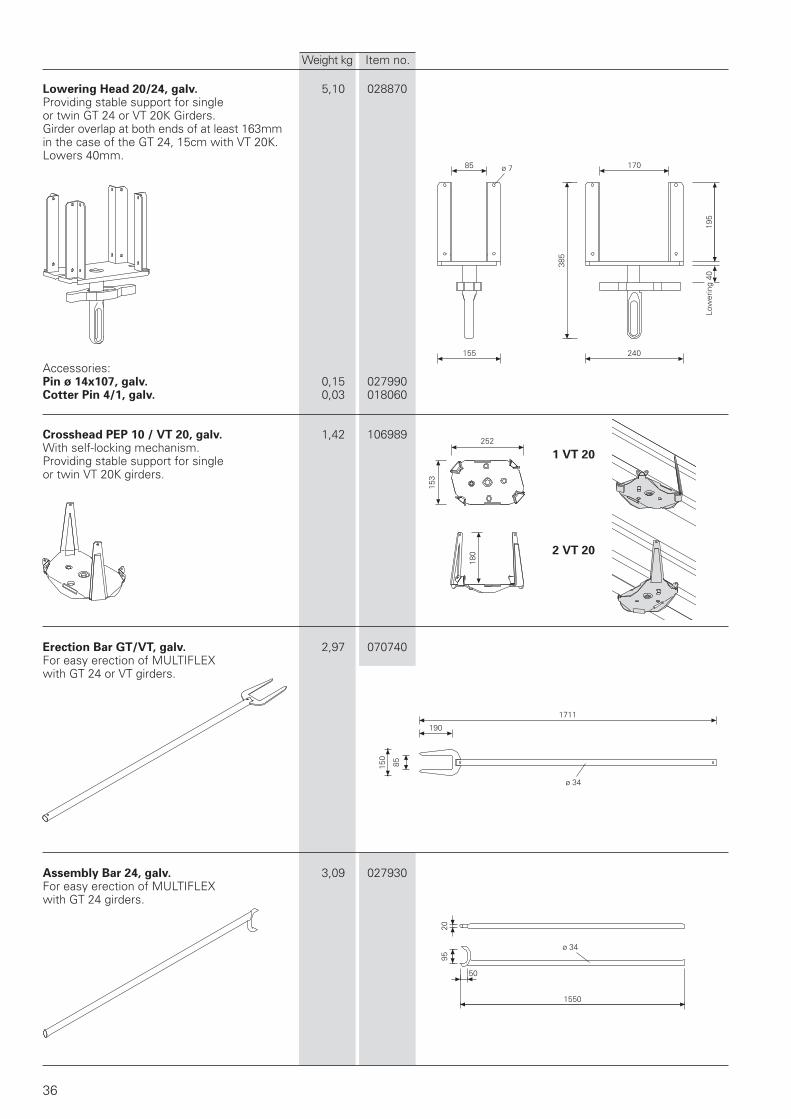
Lowering Head 20/24, galv. 5,10 028870Providing stable support for singleor twin GT 24 or VT 20K Girders.Girder overlap at both ends of at least 163mmin the case of the GT 24, 15cm with VT 20K.Lowers 40mm.
Accessories:Pin ø 14x107, galv. 0,15 027990Cotter Pin 4/1, galv. 0,03 018060
Crosshead PEP 10 / VT 20, galv. 1,42 106989With self-locking mechanism.Providing stable support for singleor twin VT 20K girders.
Erection Bar GT/VT, galv. 2,97 070740For easy erection of MULTIFLEXwith GT 24 or VT girders.
Assembly Bar 24, galv. 3,09 027930For easy erection of MULTIFLEXwith GT 24 girders.
Weight kg Item no.
Low
erin
g 40
1 VT 20
2 VT 20

210
270
110
12
ø 14
129
1104
ø 26
ø 5
ø 4
70
185
995
460
120
190
6530
37
Tension Strap 16-25, galv. 0,57 028590For clamping 2 Girders GT 24,VT 20K or VT 16K onto Crosshead20/24 (S) or Crosshead 16 (S).
Pin ø 14x107, galv. 0,15 027990For fixing Crossheads as well asClawheads etc.
Cotter Pin 4/1, galv. 0,03 018060For Pins to ø 25mm.
Handrail Holder 9,79 035700For easy and quick clamping to concreteslabs for supporting handrails.Adjustable from 20 up to 420mm.
Weight kg Item no.
min
20
max
420

ø 48 – 120
555
800
186
210
400
40
239
210
450
40
120
1
00
840
615
780
585
38
853
357
640
Universal Tripod, galv. 9,26 028000For props ø 48 to ø 120mm.Can also be used in combinationwith MULTIPROP Base MP 50.
Only to be used as an erection device!
Tripod, galv.* 8,98 027860For props ø 57 to ø 89mm.
*for hire only
Only to be used as an erection device!
Tripod PEP 10, galv. 5,40 107152For PEP 10 props ø 44 to ø 64mm.
Only to be used as an erection device!
Brace Clamp, galv. 1,85 027940Diameter of prop ø 48 up to 76mm.
Size of bracing board 30x150mm.
Brace Clamp HL, galv. 2,48 027790Diameter of prop ø 76 up to 89mmas well as 100 up to 120mm.
Size of bracing board 30x150mm.
Weight kg Item no.
Boa
rd m
ax 3
0
min ø 48max ø 76
min ø 76max 120
Boa
rd m
ax 3
0

39
ø 48
1800 750
250
3035
1150
2360 1100
2
1
9
8
7
6
5
1110
34
Stripping Cart ASW 465 363,00 102031Complete with:1 Steel traverse 140/220 ASW (1x) 32,60 102033
consisting of 3 parts2 Folding base unit 160/190 ASW (1x) 18,60 1020253 Vertical frames 70/90 ASW (6x) 4,40 1020354 Vertical frames 70/120 ASW (6x) 4,90 1020345 Entry platforms 190 ASW (2x) 14,80 1020266 Toe-board set 70/190 ASW (1x) 8,00 1020307 Double handrails 190 ASW (4x) 5,30 1020278 Diagonal braces 210 ASW (3x) 2,40 1020289 Horizontal braces 190 ASW (2x) 2,30 10202910 Wind security clip 60 ASW (8x) 0,06 10203711 Ballast 10kg ASW (12x) 10,00 102807
Packed in:Ring pallet USP 104, galvanized 65,60 100678Complete with:Lashing strap 25x5750mm (1x) 0,50 100707Scaffold Tube steel ø 48,3x3,2, L = 1,0m 3,55 026411as Ring extensions (6x)Max. platform height = 4,65mMax. working height = 6,65mPlatform height alterations
= 300mm
Ring pallet USP 104, galv.Observe operating instructions!
Lifting device to BGR 500 Permissible load: 1200kg
Stripping Cart, Alu 77,00 035500Platform height: up to 2,00mPermissible load: 100kg/m2
Weight kg Item no.
hand
rail
heig
ht 9
80
plat
form
hei
ght
2000
266
240
68
50 86
400
240
500
762
1439
140
67
122
132
2759040
–220
67
40
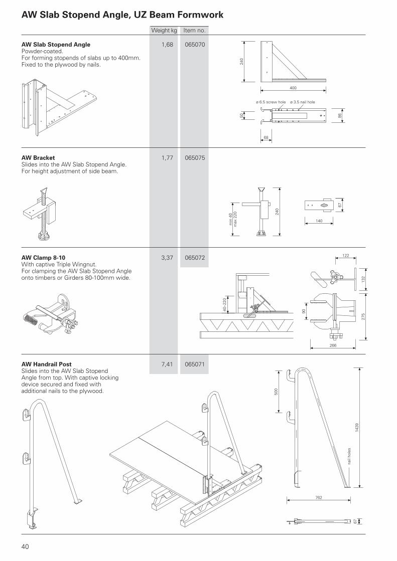
AW Slab Stopend Angle 1,68 065070Powder-coated.For forming stopends of slabs up to 400mm.Fixed to the plywood by nails.
AW Bracket 1,77 065075Slides into the AW Slab Stopend Angle.For height adjustment of side beam.
AW Clamp 8-10 3,37 065072With captive Triple Wingnut.For clamping the AW Slab Stopend Angleonto timbers or Girders 80-100mm wide.
AW Handrail Post 7,41 065071Slides into the AW Slab StopendAngle from top. With captive lockingdevice secured and fixed withadditional nails to the plywood.
Weight kg Item no.
AW Slab Stopend Angle, UZ Beam Formwork
ø 6.5 screw hole ø 3.5 nail hole
nail
hole
s
min
40
max
220

500
440
500
155
84
69
35
26
ø 7
ø 17
ø 7
210
81
42
50
165420165
963
70081,5 70
50
ø 7ø 14
210
81
42
310
50
310310310
1453
17x70=1190
50
7081,5
ø 7ø 14
60
1000
120
180
40
80
ø 14
41
UZ Beam Bracket 40 12,10 065056Complete with:Captive Hook Tie and WingnutCounterplate DW15.
For allowable spacing see PERI tables.
UZ Beam Width Adjustment Bar 80 7,44 065057Beam width max. 400mm.Beam width more than 400mm 2 or more ofthe Adjustment Bars 80 to be connected.
UZ Beam Width Adjustment Bar 129 10,30 065065Beam width max. 900mm.Beam width more than 900mm.2 or more of the Adjustment Bars 129to be connected.
UZ Beam Yoke Waler 100 9,02 065058For bearing one or two Girders GT 24at each side.
For additional girder support.Can be mounted either on standardprops or shoring systems.
Weight kg Item no.
87
15012080
64
150
120
80
10 7564
BA
75
10
64
ø 40
ø 14
100
150
ø12,5
ø42
80 200
500
ø 89
ø 17
ø 17
42
MULTIPROP and Accessories
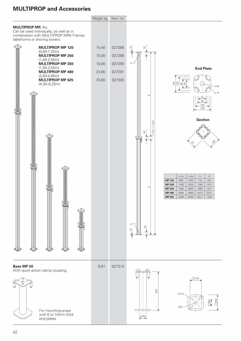
MULTIPROP MP, AluCan be used individually, as well as incombination with MULTIPROP MRK Framestableforms or shoring towers.
MULTIPROP MP 120 10,40 027288(0,80-1,20m)MULTIPROP MP 250 15,00 027289(1,45-2,50m)MULTIPROP MP 350 18,80 027290(1,95-3,50m)MULTIPROP MP 480 23,80 027291(2,60-4,80m)MULTIPROP MP 625 33,60 027305(4,30–6,25m)
Base MP 50 8,81 027310With quick action clamp coupling.
For mounting propswith 6 to 10mm thickend plates.
Weight kg Item no.
L min. L max. A B
MP 120 800 1200 715 421
MP 250 1450 2500 1365 1071
MP 350 1950 3500 1865 1571
MP 480 2600 4800 2515 2221
MP 625 4300 6250 4211 1975
Section
End Plate
L m
in –
L m
ax

B
100
8B
AD1
6
8410
0
D2
L
ø 14
ø 9
40
100
80
120
A
L
D2
D1
ø 14
ø 9
40
100
80
120
82
43
Weight kg Item no.
Props PEP 20, galv.
PEP 20-300 L = 1,71-3,00m 15,70 103058PEP 20-350 L = 1,96-3,50m 19,20 103059PEP 20-400 L = 2,21-4,00m 22,70 103060PEP 20-500 L = 2,71-5,00m 30,50 103061
For load capacity refer toPERI Formwork Design Tables.
Props PEP 30, galv.
PEP 30-150 L = 0,96-1,50m 10,40 103066PEP 30-250 L = 1,46-2,50m 15,00 103067PEP 30-300 L = 1,71-3,00m 18,70 103062PEP 30-350 L = 1,96-3,50m 22,70 103063PEP 30-400 L = 2,21-4,00m 27,20 103065
For load capacity refer toPERI Formwork Design Tables.
End Plate
20-300 20-350 20-400 20-500
A 1602 1852 2102 2602
B 143 93 143 143
D1 ø 66.0 ø 71.5 ø 75.5 ø 84.0
D2 ø 54.0 ø 59.5 ø 63.5 ø 72.0
End Plate
30-150 30-250 30-300 30-350 30-400
A 852 1352 1602 1852 2102
B 93 93 143 93 143
D1 ø 66.0 ø 66.0 ø 71.5 ø 75.5 ø 84.0
D2 ø 54.0 ø 54.0 ø 59.5 ø 63.5 ø 72.0
PEP 20, PEP 30 Props

44

45

46
02 PERI S.A.S.
Zone Industrielle Nord
34-36 rue des Frères Lumière
77109 Meaux Cedex [email protected]
www.peri.fr
03 PERI AG
Aspstraße 17
8472 Ohringen [email protected]
www.peri.ch
04 PERI S.A. Sociedad
Unipersonal
Ctra. Paracuellos -
Fuente el Saz km. 18,9
Camino de Malatones, km. 0,5
28110 Algete/Madrid [email protected]
www.peri.es
05 N.V. PERI S.A.
Industriepark
Nijverheidsstraat 6 PB 54
1840 Londerzeel [email protected]
www.peri.be
06 PERI B.V.
v. Leeuwenhoekweg 23
Postbus 304
5480 AH-Schijndel [email protected]
www.peri.nl
07 PERI Formwork Systems, Inc.
7135 Dorsey Run Road
Elkridge, MD 21075 [email protected]
www.peri-usa.com
08 PT Beton Perkasa Wijaksana
P.O. Box 3737
Jakarta 10210 [email protected]
www.peri.de
09 PERI S.p.A.
Via G. Pascoli, 4
20060 Basiano (MI) [email protected]
www.peri.it
10 PERI Japan K.K.
7F Hakozaki 314 Building,
31-4 Hakozaki-cho,
Nihonbashi Chuo-ku
Tokyo 103-0015 [email protected]
www.perijapan.jp
11 PERI Ltd.
Market Harborough Road
Clifton upon Dunsmore
Rugby, CV23 0AN [email protected]
www.peri.ltd.uk
12 PERI Kalıp ve İskeleleri
San. ve Tic. Ltd. Sti.
Çakmaklı Mahallesi
Akçaburgaz Cad.
72. Sokak No: 23
Kıraç - Büyükçekmece/ Istanbul 34500 [email protected]
www.peri.com.tr
13 PERI Kft.
Zádor u. 4.
1181 Budapest [email protected]
www.peri.hu
14 PERI Formwork Malaysia
Sdn. Bhd.
Unit 19-07-4, Level 7
PNB Damansara
19 Lorong Dungun
Damansara Heights
50490 Kuala Lumpur [email protected]
www.perimalaysia.com
15 PERI ASIA Pte. Ltd
Formwork Pte. Ltd.
No. 1 Sims Lane # 06-10
Singapore 387355 [email protected]
www.periasia.com
16 PERI Ges.mbH
Traisenstraße 3
3134 Nußdorf ob der Traisen offi [email protected]
www.peri.at
17 PERI spol. s r.o.
Průmyslová 392
252 42 Jesenice [email protected]
www.peri.cz
18 PERI Danmark A/S
forskalling og stillads
Greve Main 26
2670 Greve [email protected]
www.peri.dk
19 PERI Suomi Ltd. Oy
Hakakalliontie 5
05460 Hyvinkää [email protected]
www.perisuomi.fi
20 PERI NORGE AS
Kobbervikdalen 156
3036 Drammen [email protected]
www.peri.no
21 PERI Polska Sp. z o.o.
ul. Stołeczna 62
05-860 Płochocin [email protected]
www.peri.pl.pl
22 PERIform SVERIGE AB
Montörgatan 4-6
Box 9073
30013 Halmstad [email protected]
www.periform.se
23 PERI (Korea) Ltd.
8-9th Fl., Yuseong Bldg.
830-67, Yeoksam-dong,
Kangnam-ku,
Seoul 135-080 [email protected]
www.perikorea.com
24 PERIcofragens Lda.
Cofragens e Andaimes
Rua Cesário Verde,
nº 5 - 3º Esq.
Linda-a-Pastora 2790-326 Queijas [email protected]
www.peri.pt
25 PERI S.A.
Ruta Nacional N°. 9, km 47,5
(Panamericana Ramal Escobar)
(1625) Escobar/Prov. Bs. As. [email protected]
www.peri.com.ar
26 PERI Formas e
Escoramentos Ltda.
Rodovia Raposo Tavares,
km 41
Colinas Bandeirante
CEP 06730-000 Vargem Grande Paulista São Paulo [email protected]
www.peribrasil.com.br
27 PERI Chile Ltda.
C/José de San Martin N° 104
Parque Industrial Los
Libertadores
Colina, Santiago de Chile [email protected]
www.peri.cl
28 PERI România SRL
Calea Bucureşti nr. 2B
077015 Baloteşti - ILFOV [email protected]
www.peri.ro
29 PERI SLOWENIEN
Goran Opalic
Obrežna 137
2000 Maribor [email protected]
www.peri.de
30 PERI spol. s r.o.
Šamorínska 18
903 01 Senec [email protected]
www.peri.sk
31 PERI Australia Pty. Ltd.
116 Glendenning Road
Glendenning NSW 2761 [email protected]
www.periaus.com.au
32 PERI AS
Valdmäe 8
Tänassilma Tehnopark
76401 Saku vald Harjumaa
www.peri.ee
2
1
3
4
5
6
9
11
12
1316
17
18
19
20
22
21
24
2829
30
32
33
34
38
41
42
46
48
52
53
01 PERI GmbH Rudolf-Diesel-Strasse
89264 Weissenhorn
www.peri.de
France
Switzerland
Spain
Belgium/Luxembourg
Netherlands
USA
Indonesia
Italy
Japan
United Kingdom/Ireland
Turkey
Hungary
Malaysia
Singapore
Austria
Czech Republic
Denmark
Finland
Norway
Poland
Sweden
Korea
Portugal
Argentina
Brazil
Chile
Romania
Slovania
Slovakia
Australia
Estonia
PERI International

47
33 PERI Hellas Ltd.
Sokratous Str.
5th kil. Koropi-Varis Ave.
P. O. Box 407
194 00 Koropi [email protected]
www.perihellas.gr
34 PERI SIA
Granita 26
1057 Riga [email protected]
www.peri-latvija.lv
35 PERI (L.L.C.)
Brashy Building,
Offi ce No. 212
Shk. Zayed Road
P.O. Box 27933
Dubai [email protected]
www.perime.com
36 PERI Formwork Systems, Inc.
45 Nixon Road
Bolton, Ontario L7E 1K1 [email protected]
www.peri.ca
37 PERI GmbH
Lebanon Representative
Offi ce
AYA Commercial Center,
7th fl oor,
Dora Highway,
Beirut P.O. Box 90 416 Jdeidet
www.peri.de
38 PERI UAB
Titnago st. 19
02300 Vilnius [email protected]
www.peri.lt
39 PERI S.A.
Route de Rabat, km. 5
Piste de Beni Touzine
Tanger [email protected]
www.peri.de
40 PERI Formwork
Engineering Ltd
16 Moshe Dayan st.,
P.O. Box 10202
Petach Tikva,
49002 Israel [email protected]
www.peri.co.il
41 PERI BULGARIA EOOD
Kv. Vragdebna
m. Nova Machala Nr. 46
1839 – Sofi a [email protected]
www.peri.bg
42 MEST ltd.,
Fornubudum 5
220 Hafnarfjordur [email protected]
www.mest.is
43 TOO PERI Kazakhstan
Rubenstein Street 10
(Corner Dostyk Str. 7)
050010 Almaty [email protected]
www.peri.kz
44 OOO PERI
8 Etage, OOO PERI Buro
Krasnaya Presnya Str. 24
123022 Moskau [email protected]
www.peri.ru
45 PERI Wiehahn (Pty.) Ltd.
P.O. Box 2668
Bellville 7535 [email protected]
www.periwiehahn.co.za
46 TOW PERI Ukraina
23, M. Raskowa Str., B. 822
02002 Kiew [email protected]
www.peri.ua
47 PERI GmbH
Egypt Branch Offi ce
24 A, Obour Gardens,
4th Floor, apt. # 1
Salah Salem Street
11361 Heliopolis Cairo [email protected]
www.peri.com.eg
48 PERI Oplate d.o.o.
Jurija Gagarina 81
11070 Novi Beograd offi [email protected]
www.peri.co.yu
49 PERI Cimbras y Andamios,
S.A. de C.V.
Parque de las Américas
KM 3.5 de la Carretera
Jorobas - Tula
Huehuetoca
Estado de México, C.P. 54680 [email protected]
www.peri.com.mx
50 PERI Kalıp ve İskeleleri
Baku Branch Offi ce
28 May Küç. Ev 72 Menzil 27
Baku [email protected]
www.peri.com.tr
51 PERI Kalıp ve İskeleleri
Aşgabat Branch Offi ce
Göroglu Sokak No. 130, Kat 2
744035 Aşgabat [email protected]
www.peri.com.tr
52 PERI Belarus
Pr. Nesawisimosti 11
Kopus-2 Zimmer: 526,528
220030 Minsk [email protected]
www.peri.com.tr
53 PERI oplate i skele d.o.o.
Dolenica 20
10 250 Donji Stupnik/ Zagreb [email protected]
www.peri.com.hr
54 PERI GmbH
Iran Branch Offi ce
Flat 27, Blvd. KAVE,
Building No. 246
P.O. Box 9 3979 3669
Tehran [email protected]
www.peri.ir
55 PERI (India) Pvt Ltd
717 Palm Springs
Palm Court
Malad Link Road
Malad (West)
Mumbai – 400064 [email protected]
www.peri.in
56 PERI Jordan
Saad 5 Center, 4th Floor
Offi ce No. 404
Al Madineh
Al Munawara Street
P.O. Box 367
11947 Amman [email protected]
www.peri.de
57 PERI Kuwait
Arraya Center, 29th Floor
Al-Shuhada Street, Sharq
P.O. Box 1060 Safat
13011 Kuwait [email protected]
www.peri.de
58 PERI Saudi Arabia
33 AL-Batraa Street
AL -Shurbatiy Building
AL - Bughdadiah AL -
Gharbiah Distrect
6th Floor, Flat # 61
P.O. Box 11641
Jeddah [email protected]
www.peri.de
59 PERI Qatar LLC
P.O. Box 24133
Doha [email protected]
www.peri.de
60 Société PERI S.A.S.
Bureau de liaison d‘Alger
50 bis, Route de Gué
de Constantine
Hai El Badr (ex Apreval)
Immeuble FADLI
Kouba - Alger [email protected]
www.peri.fr
7
8
10
1415
23
25
26
27 31
35
36
3739 40
43
44
45
4749
50 51
54
595558
5760 56
Greece
Latvia
United Arab Emirates
Canada
Libanon
Lithuania
Marocco
Israel
Bulgaria
Iceland
Kazakhstan
Russian Federation
South Africa
Ukraine
Egypt
Serbia
Mexico
Azerbaijan
Turkmenistan
Belorussia
Croatia
Iran
India
Jordan
Kuwait
Saudi Arabia
Qatar
Algeria

D e
11
/20
07
3m
a
Art
. N
r.:
79
19
32
©
Co
pyri
gh
t by P
ER
I G
mb
H
Wall FormworkPanel Formwork
Girder Formwork
Circular Formwork
Facade Formwork
Brace Frame
Column FormworkSquare
Rectangular
Circular
Slab FormworkPanel Formwork
Beam Grid Formwork
Girder Formwork
Slab Table
Beam Formwork
Shoring SystemsSteel Slab Props
Aluminium Slab Props
Tower Systems
Heavy-Duty Props
Climbing SystemsClimbing Scaffold
Self-Climbing System
Climbing Protection Panel
Platform Systems
Scaffold, Stairways, Working PlatformsFacade Scaffold
Working Platform
Weather Protection Roof
Stairway Access
Bridge and Tunnel FormworkCantilevered Parapet Carriage
Cantilevered Parapet Platform
Engineer´s Construction Kit
ServicesFormwork Assembly
Cleaning / Repairs
Formwork Planning
Software
Statics
Special Constructions
Additional Systems
Plywood
Formwork Girders
Stopend Systems
Pallets
Transportation Containers
PERI GmbHFormwork Scaffolding EngineeringP.O. Box 1264
89259 Weissenhorn
Germany
Tel +49 (0)73 09.9 50- 0
Fax +49 (0)73 09.9 51- 0
www.peri.de
PERI Product Range