multi-user gain maximum eigenmode beamforming, and idma · 1 multi-user gain maximum eigenmode...
TRANSCRIPT

1
Multi-User Gain Maximum Eigenmode Beamforming,
and IDMA
Peng Wang and Li PingCity University of Hong Kong
2
Contents
IntroductionMulti-user gain (MUG)Maximum eigenmode beamforming (MEB)MEB performance analysisSIMO, MEB and optimal MIMO Implementation of MEB using IDMAConclusions

3
For detail see
Peng Wang and Li Ping, “On multi-user gain in MIMO systems with rate constraints,” IEEE GlobeCom, Washington, DC, USA, Nov. 26-30, 2007.

4
Contents
IntroductionMulti-user gain (MUG)Maximum eigenmode beamforming (MEB)MEB performance analysisSIMO, MEB and optimal MIMO Implementation of MEB using IDMAConclusions

5
A 8×8 MIMO System
Great performance, but do we want to buy such a bulky handset?
Also, performance may be seriously affected by imperfect feedback and correlation among antennas.

6
Advantage of MIMO
R (bits/symbol)
MSP
(dB
)
4 4×
1 4×
0 1 2 3 4 5 6 7 8
-5
0
5
10
15
20
25
Rate
AveragePower
4 ×4
1×4

7
Can we do better?

8R (bits/symbol)
MSP
(dB
)
0 1 2 3 4 5 6 7 8
-5
0
5
10
15
20
25
Rate
AveragePower
1×4 single user 4 ×4 single user
4 ×4 multi-user
Multi-user MIMO

9
The Problems with Multi-user MIMOOptimized multi-user MIMO are very complicated, involving
- decoding order optimization,- correlation matrix optimization,- singular value decomposition (SVD),- eigenmode water filling.

10
The Focus of This Talk
- What are the advantages of multi-user MIMO? - Are there simple approaches to multi-user MIMO?
11
Contents
IntroductionMulti-user gain (MUG)Maximum eigenmode beamforming (MEB)SIMO, MEB and MIMO Implementation of MEB using IDMAConclusions

12
Multi User Gain
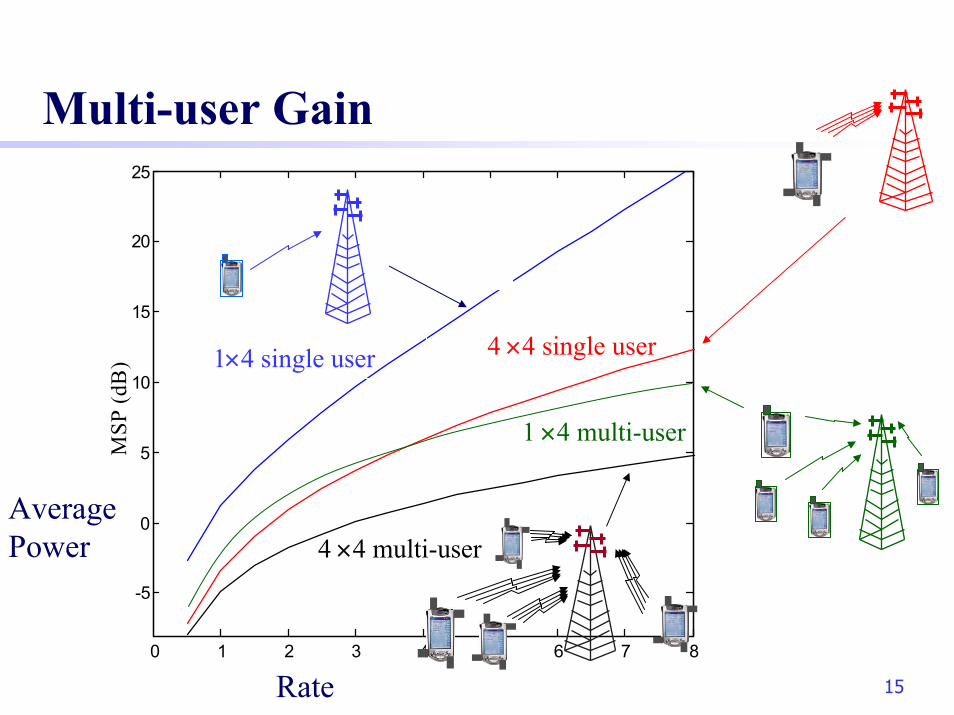
We know that power saving can be achieved by multi-user concurrent transmission. But how much is the multi-user gain (without scheduling)?
MUG

13Rate
AveragePower
1×4 single user
Multi-user Gain for SIMO
1 ×4 multi-user

14Rate
AveragePower
4 ×4 single user
4 ×4 multi-user
Multi-user Gain for MIMO
15R (bits/symbol)
MSP
(dB
)
0 1 2 3 4 5 6 7 8
-5
0
5
10
15
20
25
Rate
AveragePower
1×4 single user 4 ×4 single user
4 ×4 multi-user
Multi-user Gain
1 ×4 multi-user

16
(1) There is subtle difference between multi-user gain and multi-user diversity gain (used by David Tse).
- The former is for up-link multi-user concurrent transmission. - The latter is for down-link opportunistic transmission.
(2) For the down-link, multi-user detection is more difficult. Thus single-user opportunistic transmission becomes attractive.
(3) For the up-link, multi-user detection is relatively easier.(4) Quasi-static fading model.(5) No scheduling is assumed. (Fixed rates.)
Notes

17
What is the reason of multi-user gain?
For detail, seePeng Wang, Jun Xiao, and Li Ping, "Comparison of orthogonal and non-orthogonal approaches to future wireless cellular systems," IEEE Vehicular Technology Magazine, vol. 1, no. 3, pp. 4-11, Sept. 2006.

18
Stripping Decoding
Decode x’’ by treating x’ as noise
Decoding x’
)'
''1(log2/ 2 qNqR+
+=
)'1(log2/ 2 NqR +=
t
arrival power q’’
arrival power q’t
Assume that q’’ > q’.

19
Power Matching Strategy
channel gain g1user-2 signal
channel gain g2user-1 signal
arrival power q2
arrival power q1
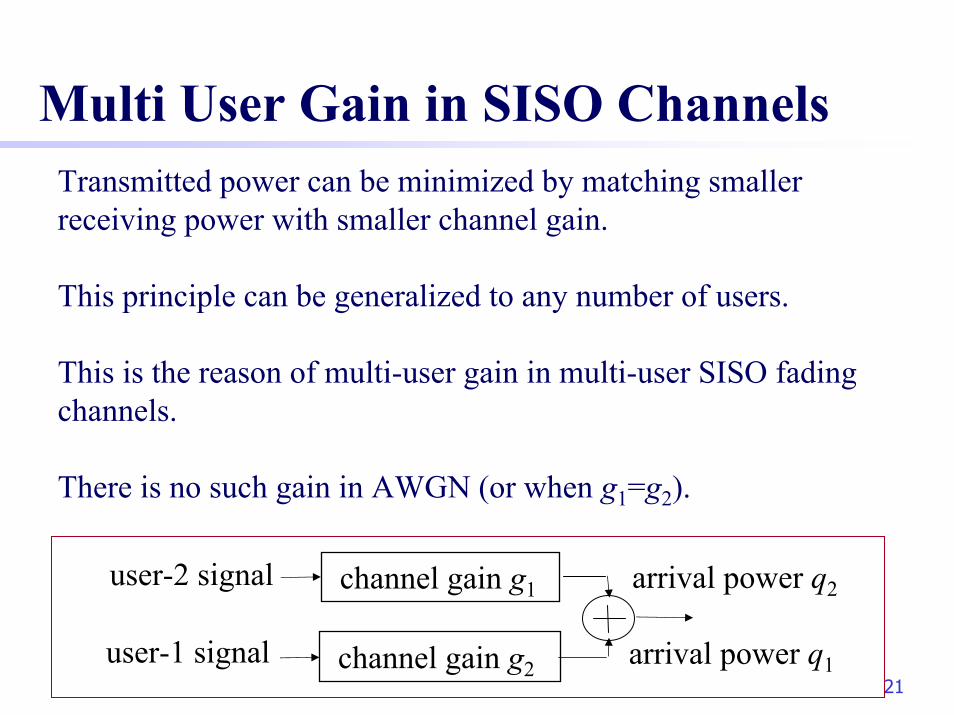
The question is to assign (q’, q ‘’) to (q1, q2). If we do it randomly, the resultant sum-power is the same as TDMA.
However, we can do better.
q’’t tq’>

20
Power Matching Strategy
channel gain g1user-2 signal
channel gain g2user-1 signal
arrival power q2
arrival power q1
(1) Assign q2=q’’ and q1=q’. Thensum transmitted power = q’’ /g2 + q’ /g1
(2) Assign q2=q’ and q1=q’’. Thensum transmitted power = q’’ /g1 + q’ /g2
Assume q’’ > q’ . Which method leads to smaller transmitted power?
q’’t tq’>
21
Multi User Gain in SISO ChannelsTransmitted power can be minimized by matching smaller receiving power with smaller channel gain.
This principle can be generalized to any number of users.
This is the reason of multi-user gain in multi-user SISO fadingchannels.
There is no such gain in AWGN (or when g1=g2).
channel gain g1user-2 signal
channel gain g2user-1 signal
arrival power q2
arrival power q1

22
Multi-User Gain in MIMO ChannelsIn a MIMO channel, there is one more reason for multi-user gain. A MIMO system provides more dimensions for signaling. This is explained in the following example.
If there is one user, we need more antennas to achieve these degrees of freedoms.
However, if there are multiple users, we can achieve these degrees of freedoms more easily by allowing con-current transmission.
Three receiver antennas can provide a maximum three degrees of freedom. We need the help of the transmitters to achieve this degree of freedom. (We may view each degree of freedom as an eigenvector.)

23
An Example: 2×2 MAC
More concurrent transmitting user, more gain.
0 1 2 3 4 5 6 7 8
0
5
10
15
20
25
R (bits/symbol)
aggregate power (dB)
K = 1 (TDMA)
K = 2K = 4K→∞

24
Delay sensitive services without scheduling.
Perfect channel state information (CSI).
Channel includes path loss, lognormal and Rayleigh fading
Assumptions
r
Rayleigh fading
Lognormal fading
Path loss

25
Contents
IntroductionMulti-user gain (MUG)Maximum eigenmode beamforming (MEB)MEB performance analysisSIMO v.s. MIMOImplementation of MEB using IDMAConclusions

26
The MEB Strategy
Each mobile transmits only on its maximum eigenmode.
Power allocation is applied according to the maximumeigenmode gains {gk}.
Stripping decoding is applied at the receiver. The user with the largest channel gain is decoded first.

27
The Advantages of MEB
simple and nearly optimal.

28
Optimal MIMO MAC and MEB
Optimal MIMO MAC
MEB

29
Contents
IntroductionMulti-user gain (MUG)Maximum eigenmode beamforming (MEB)MEB performance analysisSIMO, MEB and MIMOImplementation of MEB using IDMAConclusions

30
Theorem 1
When K→ ∞, the MSP for a multi-user N×M MIMO system is given by
∫∞
××
×
=0
/)(
)(22ln),( dxxfx
RRKMSP MN
MxRF
MN
MN
K: the number of users number;R: sum rate;FM×N(x) the CDF of |λmax|2; fM×N(x) the PDF of |λmax|2;

31
Theorem 2
When K→ ∞, the MSP for a multi-user MEB N×M MIMO system is given by
Therefore MEB is asymptotically optimal.
∫∞
××
×
=0
/)(
)(22ln),( dxxfx
RRKMSP MN
MxRF
MN
MN

32
Proof Outline
The derivation is based on upper and lower bounds.
When K→ ∞, the upper and lower bounds converge so we obtain the true MSP.
The upper bound is derived from a realizable system using maximum eigenmode beamforming (MEB).
The lower bound is derived from an idealized parallel channel.

33
Upper Bound (Achievability)
KKkFRRKMSP
K
Kk MN
MKkR
MN1
)/(2)1(2ln),( 1
/)1(
⋅+
≤ ∑=
−×
−
×ε
δ
The MEB provides an upper bounds on the MIMO MSP.
where δ is an arbitrarily small constant, ε the outage probability and FN×M(⋅) the CDF of the maximum singular value.
When K→ ∞,
∫ −×
× ≤1
0 1
/
)(22ln),( dt
tFRRKMSP
MN
MRt
MN

34
Proof
( )( ) ( )
( )( ) ( )
1/ /
11 / /1
2 1 1 (2 1) / 1lim
11 2 1 1 (2 1) / 1
kR K R K
k iK k R K R Ki
MSNR
MM
δ
δ
−
−→∞ −
=
− + − +=
+ − + − +∑
( )( )( )
1/ /
/ 11 /1
2 1 1 (2 1) /
2 11 1 (2 1) /
kR K R K
R K ik R K
M
MM
−
−−
=
− + −≥
−+ + −∑ i
/2 1R K= −
2 2, m ax , m ax , m ax
1 2 2, m ax , m ax , m ax1
|
1 |
Hk k k k
k k Hi i k ii
p dS N R
p d−
=
=+ ∑
| u u
| u u
2,max
1 2,max1
1k k
ki ii
p d
p d φ−
=
=+∑ k,i
( ) ( 1) /
1
1 2 ln 2 1lim lim( / )
R k MKK K
kK Kk K k K N M
Rp
KF k Kε ε
δ −
−→∞ →∞= = ×
+= ⋅∑ ∑
/1
1
2(1 ) ln 2( )
Rt M
N M
R dtF tε
δ −×
= + ⋅ ∫
35
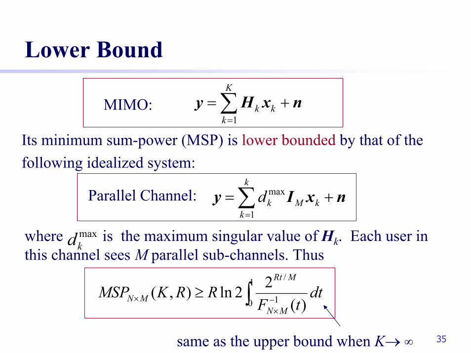
Lower Bound
∫ −×
× ≥1
0 1
/
)(22ln),( dt
tFRRKMSP
MN
MRt
MN
∑=
+=k
kkMkd
1
max nxIy
maxkd
1
K
k kk=
= +∑y H x n
Its minimum sum-power (MSP) is lower bounded by that of thefollowing idealized system:
MIMO:
Parallel Channel:
where is the maximum singular value of Hk. Each user in this channel sees M parallel sub-channels. Thus
same as the upper bound when K→ ∞

36
When K→ ∞, the upper and lower bounds converge to
End of the Proof
∫∞
××
×
=0
/)(
)(22ln),( dxxfx
RRKMSP MN
MxRF
MN
MN

37
Observations
MEB is asymptotically optimal when K→ ∞.
MEB is nearly optimal even for a quite small K.
MEB is insensitive to antenna correlation.
MEB is insensitive to CSI error.
For detail, seeLi Ping and Peng Wang, "Multi-user gain and maximum eigenmodebeamforming for MIMO systems with rate constraints," IEEE Inform. Theory Workshop (ITW), Bergen, Norway, July 1-6, 2007.

38
Optimal MIMO MAC and MEB
Optimal MIMO MAC
MEB

39
MEB Is Nearly Optimal
AveragePower
rate (bits/channel use)
2×2 MIMO MAC

40
Summary
MIMO asymptotic MSP
The degrees of freedom is increased by M times.Why M? Effectively, we have a KN× M system. The limiting factor is M.What is the impact of N? FN×M(⋅)
∫∞
××
×
=0
/)(
)(22ln),( dxxfx
RRKMSP MN
MxRF
MN
MN

41
Delay sensitive services without scheduling.
Perfect channel state information (CSI).
Channel includes path loss, lognormal and Rayleigh fading
Conditions
r
Rayleigh fading
Lognormal fading
Path loss

42
Contents
IntroductionMulti-user gain (MUG)Maximum eigenmode beamforming (MEB)MEB performance analysisSIMO, MEB and optimal MIMO Implementation of MEB using IDMAConclusions

43
Comparison of Different Gains
R (bits/symbol)
MSP
(dB
)
4 4×
2 4×
1 4×
1 4×
4 4×2 4×
1K =
K =∞
0 1 2 3 4 5 6 7 8
-5
0
5
10
15
20
25
multi-user SIMO
multi-user MEB
single-user SIMO
BFgain
multi-user gain
K=16 multi-user MIMO
optimization gain
single-user MIMO
MIMO gain
single-userSIMO
Single-userMIMO
multi-userSIMO
Multi-userMEB
multi-userMIMO

44
Some details …
For detail, seePeng Wang and Li Ping, “On multi-user gain in MIMO systems with rate constraints,” IEEE GlobeCom, Washington, DC, USA, Nov. 26-30, 2007.
45
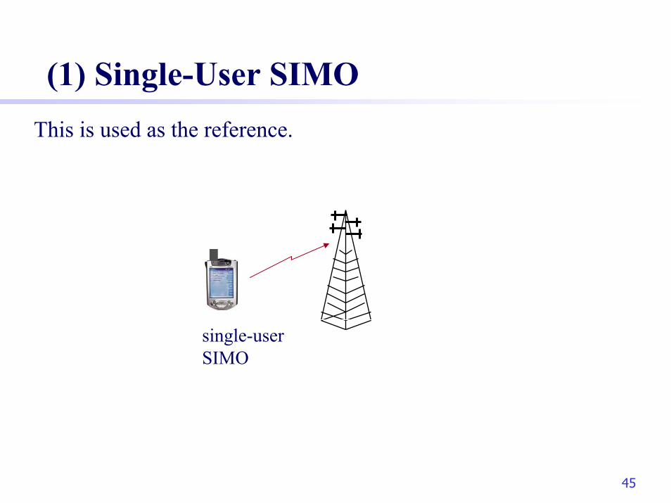
(1) Single-User SIMOThis is used as the reference.
single-userSIMO

46
(2) Single-User MIMOSVD is sensitive to channel information error (water-filling).
Bulky .
Closely located antennas may be rank-deficient. This is a serious problem for a handset unit.

47
(3) Multi-User SIMOSIMO MAC is a special case of MIMO MAC.
SIMO MAC can also achieve good MUG.
SIMO MAC requires only one antenna per handset.

48
(4) Multi-User MEBEasy to design (no water filling).
Robust against imperfect CSI
Near optimal performance with multi-user detection.
But, multiple transmit antennas.
Rank deficiency is not a problem.

49
(5) Multi-User MIMOVery sensitive to channel information error.
Bulky .
Very complicated to optimize.

50
Comparison of Different Gains
R (bits/symbol)
MSP
(dB
)
4 4×
2 4×
1 4×
1 4×
4 4×2 4×
1K =
K =∞
0 1 2 3 4 5 6 7 8
-5
0
5
10
15
20
25
multi-user SIMO
multi-user MEB
single-user SIMO
BFgain
multi-user gain
K=16 multi-user MIMO
optimization gain
single-user MIMO
MIMO gain
single-userSIMO
Single-userMIMO
multi-userSIMO
Multi-userMEB
multi-userMIMO

51
Types of Gains in Multi-User MIMO
- MIMO gain achievable by single-user MIMO
- Multi-user gain achievable by multi-user SIMO
- Beamforming gain achievable by multi-user MEB
- Optimization gain achievable by multi-user MIMO
single-userSIMO
Single-userMIMO
multi-userSIMO
Multi-userMEB
multi-userMIMO

52
Optimization Gain
Optimization involvesdecoding order optimization,correlation matrix optimization,singular value decomposition (SVD),eigenmode water filling.
Therefore to achieve optimization gain is a very complicated task.
As we can see, the difference between MEB and optimal MIMO Is marginal. Thus optimization gain is not significant.

53
Contents
IntroductionMulti-user gain (MUG)Maximum eigenmode beamforming (MEB)MEB performance analysisSIMO v.s. MIMOMulti-user gain (MUG)Implementation of MEB using IDMAConclusions

54
MEB-Based IDMA
1p
Kp
1c 1x
KπKc Kx
1π
1π
Kπ
Kπ
1π

55
Performance of MEB-Based IDMA
R = 4 bits/symbol

56
Based on the MAC-BC duality principle (Yu, Cioffi, Vishwanath, Jindal, Goldsmith), the conclusions in this talk can be also applied to BC channels. For simplicity, we will concentrate on MIMO MAC below.
MIMO Broadcasting and Duality

57
Contents
IntroductionMulti-user gain (MUG)Maximum eigenmode beamforming (MEB)MEB performance analysisSIMO v.s. MIMOImplementation of MEB using IDMAConclusions

58
Conclusions
Optimal MIMO systems are bulky and sensitive. They are also complicated to design and to decode.
Multi-user SIMO can achieve very impressive gain.
If multiple antennas are affordable, MEB is a low-cost, almost optimal strategy.
IDMA provides an efficient framework to realize MUG.

59
Thank You !