multi-stand msa200 manual.pdf · 2018-03-23 · multi-stand msa200 operating and safety...
TRANSCRIPT

Multi-Stand MSA200
www.tritontools.com
Operating and Safety Instructions
Bedienings- en veiligheidsvoorschriften
Instructions d’utilisation et consignes de sécurité
Gebrauchs- und Sicherheitsanweisung
Istruzioni Per L’uso E La Sicurezza
Instrucciones de uso y de seguridad

2
GB
CONTENTS
Thank you for purchasing this Triton tool. These instructions contain information necessary for safe and effective operation of this product.
Please read this manual to make sure you get the full benefit of its unique design.Keep this manual close to hand and ensure all users of this tool have read and fully understand the instructions.
Contents / Symbols / Parts List
PARTS LIST
Symbols 2Parts List 2Assembly 4Warranty 4
SYMBOLS Always wear ear, eye and respiratory protection
Instruction warning
Do not use before viewing and fully understanding the operating instructions
A. Main Body Assembly (1)B. Saddles (4)C. Front Quadrant (1)D. Rear Quadrant (1)E. Hex Bolt (M6 x 60mm) (1)F. Small Washer (2)G. Nyloc Nut (M6) (1)H. Large Washer (1)I. Quadrant Washer (1)J. Hex Bolt (M6 x 80mm) (1)K. Round Knob & M6 Nut (1)L. Head Assembly (1)M. Pan Head Bolt (M6 x 10) (4)

3
GB
Know Your ProductPage 3
A
L
C
D
B
M
J
K
F
E
G
H
I
KNOW YOUR PRODUCT

4
GB
Assembly / Warranty
ASSEMBLYFold the legs of the Main Body Assembly (A) fully outwards. Loosen the round knob and extend the stem upwards, then tighten.Note: The legs should pivot firmly. Adjust the nuts on the leg pivot bolts if necessary.Fit the Saddles (B) to the stem using the locating pins on the saddles as shown.Attach the Front (C) and Rear (D) Quadrants using the shorter Hex Bolt (E), Small Washers (F) and Nyloc Nut (G). Do not over-tighten.Fit the Quadrant Washer (I) onto the longer Hex Bolt (J) with the hex head located in the tabs on the washer. Insert the bolt through the slots in the quadrants, ensuring that it passes through the washer held within each quadrant and the hole in the lower stem saddles. Fasten the Large Washer (H) onto the bolt with the Round Knob and M6 Nut (K). Rotate the quadrants until the flat tops are horizontal then gently nip up the round knob.Fasten the Head Assembly (L) to the quadrants using the Pan Head Bolts (M). The round knob on the clamp which is built into the head should be on the same side as the round knob on the quadrant.Adjust the nut tension on the Hex Bolt (E) if necessary. The head should pivot firmly, and should lock tightly at any selected angle when the quadrant knob is tightened.
WARNINGS• Make sure the legs are fully opened, and that both the stem clamp and the quadrant clamp are fully tightened before applying heavy loads.• Do not overload. Max. load per Multi-Stand 100kg (220lb).• Do not stand on this product.• When using the head clamp to clamp materials less than 30mm, use a packing piece.• Clamp an extension piece (ie. an offcut of sheet material - as shown on product carton) into the head channel if using Multi- Stand to support material at a height greater than its maximum adjustment.• When clamping easily damaged materials, eg. doors, use thin packing on both sides to avoid damage.
• Make sure the Multi-Stand is securely pegged down to the ground when applying non-vertical loads; or when on steeply sloping ground.
Triton Precision Power Tools guarantees to the purchaser of this product that if any part proves to be defective due to faulty materials or workmanship within 12 MONTHS from the date of original purchase, Triton will repair, or at its discretion replace, the faulty part free of charge.
This guarantee does not apply to commercial use nor does it extend to normal wear and tear or damage as a result of accident, abuse or misuse.
* Register online within 30 days.
Terms & conditions apply.
This does not affect your statutory rights
To register your guarantee visit our web site at www.tritontools.com* and enter your details.
Your details will be included on our mailing list (unless indicated otherwise) for information on future releases. Details provided will not be made available to any third party.
PURCHASE RECORD
Date of Purchase: ___ / ___ / ____
Model: MSA200
Retain your receipt as proof of purchase
WARRANTY
5
NL
Inhoud / Symbolen / Onderdelen
INHOUD
Hartelijk dank voor de aanschaf van dit Triton-gereedschap. Deze instructies geven informatie voor een veilige en doeltreffende bediening van dit product.
Lees deze handleiding zodat u de voordelen van het unieke design van dit product ten volle kunt benutten. Houd deze handleiding bij de hand en zorg ervoor dat alle gebruikers van dit gereedschap de handleiding hebben
gelezen en volledig hebben begrepen.
Symbolen 5Onderdelen 5Montage 6Garantie 6
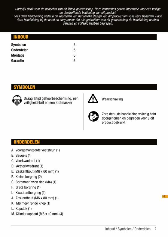
SYMBOLEN Draag altijd gehoorbescherming, een veiligheidsbril en een stofmasker
Waarschuwing
Zorg dat u de handleiding volledig hebt doorgenomen en begrepen voor u dit product gebruikt
ONDERDELEN
A. Voorgemonteerde voetsteun (1)B. Beugels (4)C. Voorkwadrant (1)D. Actherkwadrant (1)E. Zeskantbout (M6 x 60 mm) (1)F. Kleine borgring (2)G. Borgmoer nylon ring (M6) (1)H. Grote borgring (1)I. Kwadrantborgring (1)J. Zeskantbout (M6 x 80 mm) (1)K. M6 moer ronde knop (1)L. Kopstuk (1)M. Cilinderkopbout (M6 x 10 mm) (4)

6
NL
Montage / Garantie
MONTAGEVouw de poten van de voorgemonteerde voetsteun (A) helemaal naar buiten. Draai de knop los, trek de schacht omhoog en draai de knop terug vast.Opmerking: De poten dienen stijf te scharnieren. Stel de moeren van de pootbouten indien nodig bij.Maak de beugels (B) door middel van de positioneringpennen vast aan de schacht (zie afbeelding).Monteer het voor- (C) en achterkwadrant (D) met de korte zeskantbout (E), kleine borgringen (F) en de borgmoer met nylon ring (G). Draai de moer niet te hard vast.Plaats de kwadrantborgring (I) over de lange zeskantbout (J) zodat de zeskantkop in de groeven op de borgring past. Schuif de bout door de openingen in de kwadranten. Zorg er hierbij voor dat u de bout door de borgringen in elk kwadrant en de opening in de onderste beugels op de schacht schuift. Zet de grote borgring (H) op de bout vast met de ronde knop (K).Draai de kwadranten tot de platte bovenzijde evenwijdig is met de grond en draai de ronde knop voorzichtig aan.Zet het kopstuk (L) op de kwadranten vast met de cilinderkopbouten (M). De ronde knop op de klem (in het kopstuk ingebouwd) dient zich aan dezelfde kant te bevinden als de ronde knop op het kwadrant.
Stel de spanning op de scharnierbout (E) indien nodig bij. Het kopstuk dient stijf te scharnieren, en onder eender welke hoek stevig te blokkeren wanneer de kwadrantknop vastgedraaid wordt.
WAARSCHUWING • Zorg ervoor dat de poten volledig open staan, en
dat zowel de schachtklem als de kwadrantklem volledig vastgedraaid zijn voor u een zware lading op het toestel plaatst.
• Niet overbelasten. Max. lading per Multi-Stand 100 kg.
• Sta niet op dit product.• Gebruik een hoogteblok om materiaal kleiner
dan 30 mm in het kopstuk vast te klemmen. • Klem een verlengstuk (bijv. wat overschot
van plaatmateriaal – zie afbeelding op de verpakking) in het kopstuk als u de Multi-Stand gebruikt om materiaal te ondersteunen op een grotere hoogte dan de maximale hoogte van de stand.
• Gebruik bij het vastklemmen van materialen die gemakkelijk beschadigd raken, zoals deuren, wat lichte vulling aan beide zijden om schade te voorkomen.
• Zorg er indien mogelijk voor dat u de Multi-Stand stevig aan de grond vastpint wanneer u ladingen die niet vertikaal zijn op het toestel plaats, of wanneer u op sterk aflopende grond werkt.
Om uw garantie te registreren, gaat u naar onze website op www.tritontools.com* en voert u uw gegevens in.Uw gegevens worden opgeslagen in onze mailinglist (tenzij u anders aangeeft) voor informatie over nieuwe producten. De ingevulde gegevens worden aan geen enkele andere partij beschikbaar gesteld.
AANKOOPGEGEVENS
Datum van aankoop: ___ / ___ / ____Model: MSA200
Serienummer: __________________ (te vinden op motorlabel)
Bewaar uw aankoopbon als aankoopbewijs
GARANTIE
Triton Precision Power Tools garandeert de koper van dit product dat indien een onderdeel defect is vanwege fouten in materiaal of uitvoering binnen 12 MAANDEN na de datum van de oorspronkelijke aankoop, Triton het defecte onderdeel gratis repareert of, naar eigen inzicht, vervangt.
Deze garantie heeft geen betrekking op commercieel gebruik en strekt zich niet uit tot normale slijtage of schade ten gevolge van een ongeluk, verkeerd gebruik of misbruik.
* Registreer online binnen 30 dagen.
Algemene voorwaarden van toepassing.
Dit heeft geen invloed op uw statutaire rechten

7
F
TABLE DES MATIERES
Nous vous remercions d’avoir choisi cet outil Triton. Ces instructions contiennent les informations nécessaires au fonctionnement efficace et sûr de ce produit.
Veuillez lire attentivement ce manuel pour vous assurer de tirer pleinement avantage des caractéristiques uniques de votre nouvel outil.
Gardez ce manuel à portée de main et assurez-vous que tous les utilisateurs de l’outil l’aient lu et bien compris avant toute utilisation.
Table Des Matieres / Symboles / Nomenclature
Symboles 7Nomenclature 7Montage 8Garantie 8
SYMBOLES Assurez-vous de toujours porter lunettes de protection, masque respiratoire et protections antibruit
Avertissement
Ne pas utiliser avant d’avoir pris pleinement connaissance des instructions d’utilisation
NOMENCLATUREA. Bloc trépied (1)B. Etriers (4)C. Quadrant avant (1)D. Quadrant arrière (1)E. Boulon à 6 pans (M6 x 60 mm) (1)F. Petite rondelle (2)G. Ecrou auto-freiné (M6) (1)H. Grande rondelle (1)I. Plaquette pour quadrant (1)J. Boulon à 6 pans (M6 x 80 mm) (1)K. Bouton rond & écrou M6 (1)L. Bloc de tête (1)M. Boulons à tête cylindrique (M6 x 10 mm) (4)

8
F
Montage / Garantie
MONTAGEDéployez totalement les pieds du bloc trépied (A) vers l’extérieur. Dévissez légèrement le bouton rond et étirez la colonne principale vers le haut, puis resserrez le bouton rond.Nota : les pieds doivent présenter une légère résistance lors du pivotement. Au besoin, resserrez ou desserrez l’écrou du pivot de chacun des pieds.Montez les étriers (B) sur la colonne en utilisant les ergots de repérage comme indiqué sur le schéma.Fixez les quadrants avant (C) et arrière (D) au moyen du boulon à 6 pans court (E), des petites rondelles (F) et de l’écrou auto-freiné (G). Ne pas trop serrer.Insérez le boulon long à 6 pans (J) dans la plaquette pour quadrant (I) en introduisant bien la tête à 6 pans entre les ergots en V de la plaquette. Insérez le boulon dans les fentes des deux quadrants, en faisant bien attention qu’il passe par la rondelle retenue près de chaque quadrant, et par le trou des deux étriers inférieurs. Fixez la grande rondelle (H) sur le boulon à l’aide du bouton rond (K).Faites tourner les quadrants jusqu’à ce que les rebords plats supérieurs soient à l’horizontale puis vissez le bouton rond sans trop serrer.Fixez le bloc de tête (L) sur les quadrants à l‘aide des boulons à tête cylindrique (M). Le bouton rond situé sur le dispositif de serrage intégré à la tête doit se trouver du même côté que le bouton rond situé sur le quadrant.
Au besoin, ajustez la tension qu’exerce l’écrou sur le boulon de pivotement (E). La tête doit présenter une légère résistance au pivotement et doit s’arrêter avec fermeté à tout angle choisi lorsque le bouton du quadrant est resserré.
AVERTISSEMENTS • Assurez-vous que les pieds soit totalement
déployés et que les boutons de serrage de la colonne et des quadrants soient bien serrés avant de placer de lourdes charges.
• Ne surchargez pas l’outil. La charge maximale par servante multifonction est de 100 kg.
• Ne montez pas sur ce produit.• Si les objets que vous souhaitez serrer dans le
dispositif de serrage de la tête ont une épaisseur inférieure à 3 cm, utilisez un matériau de rembourrage pour compenser.
• Serrez une longueur de matériau de rallonge (par exemple une chute de planche – comme il est montré sur le carton d’emballage du produit) dans le canal de la tête si vous souhaitez utiliser votre servante multifonction pour soutenir un matériau situé plus haut que la hauteur de réglage maximale de la servante.
• Si vous souhaitez serrer des objets facilement endommageables, tels que des portes, utilisez un matériau protecteur de chaque côté pour éviter tout endommagement.
• Assurez-vous de fixer la servante multifonction au sol avant d’y appliquer des charges non verticales ou lors de travaux sur un sol en pente forte.
Triton Precision Power Tools garantit à l’acheteur de ce produit que toute pièce présentant un vice de matériau ou de fabrication dans les 12 MOIS suivants la date d’achat d’origine, sera réparée ou remplacée, à sa discrétion.
Cette garantie ne s’applique pas à l’usage commercial et ne couvre pas l’usure normale ni les dommages consécutifs à un accident, une utilisation incorrecte ou abusive.
* Enregistrement sur le site dans les 30 jours*
Acceptation des conditions.
Cela n’affecte pas vos droits légaux.
Pour enregistrer votre garantie, visitez notre site internet à www.tritontools.com* et entrez vos détails. Nous ajouterons vos détails à notre liste d’abonnés (sauf indication contraire) afin de vous tenir informés de nos nouveautés. Les détails fournis ne seront communiqués à aucune tierce partie.
INFORMATIONS D’ACHAT
Date d’achat : ___ / ___ / ____Modèle : MSA200Numéro de série : __________________ (indiqué sur la plaque du moteur)
Conservez votre reçu, il vous servira de preuve d’achat.
GARANTIE

9
D
INHALT
Vielen Dank, dass Sie sich für Triton entschieden haben. Diese Anleitung enthält wichtige Informationen für das sichere und effektive Arbeiten mit diesem Produkt. Bitte lesen Sie diese Anleitung sorgfältig durch, um den größtmöglichen Nutzen
aus dem einzigartigen Design dieses Produkts ziehen zu können.Bewahren Sie diese Anleitung griffbereit auf und sorgen Sie dafür, dass alle Benutzer dieses Geräts sie gelesen und
verstanden haben.
Inhalt / Symbole / Teileliste
Symbole 9Teileliste 9Montage 10Garantie 9
SYMBOLE Gehör-, Augen- und Atemschutz tragen
Warnhinweis
Verwenden Sie das Gerät erst, nachdem Sie die Gebrauchsanweisung sorgfältig durchgelesen und verstanden haben
TEILELISTEA. Dreifußstativ (1)B. Bügel (4) C. Vorderes Segment (1)D. Hinteres Segment (1)E. Sechskantschraube (M6 x 60 mm) (1)F. Kleine Unterlegscheibe (2)G. Sechskant-Stopmutter (M6) (1)
H. Große Unterlegscheibe (1)I. Segmentunterlegscheibe (1)J. Sechskantschraube (M6 x 80 mm) (1)K. Flügelschraube mit M6-Mutter (1)L. Kopfstück (1)M. Flachkopfschraube (M6 x 10 mm) (4)
Triton Precision Power Tools garantiert dem Käufer dieses Produkts, dass Triton, wenn sich Teile innerhalb von 12 MONATEN ab Datum des Originalkaufs aufgrund defekter Materialien oder unzulänglicher Arbeitsausführung als defekt erweisen, das defekte Teil nach eigenem Ermessen entweder reparieren oder ersetzen wird.
Diese Garantie erstreckt sich nicht auf kommerzielle Verwendung oder normalen Verschleiss oder Schäden infolge von Unfall, Missbrauch oderunsachgemäßem Gebrauch.
* Registrieren Sie sich online innerhalb von 30 Tagen.
Bedingungen gelten.
Ihre gesetzlich festgelegten Rechte werden hierdurch nicht beeinträchtigt.
Zur Registration Ihrer Garantie besuchen Sie bitte unsere Website www.tritontools.com* und geben Sie dort Ihre Details ein. Diese werden dann in unserer Postversandliste aufgenommen (wenn nicht anders angegeben), damit wir Sie über zukünftige Neueinführungen informieren. Ihre Details werden keinen dritten Parteien zugänglich gemacht.
KAUFINFORMATION
Datum des Kaufs: ___ / ___ / ____
Modell: MSA200
Seriennummer: __________________ (Auf dem Motortypenschild)
Behalten Sie Ihren Beleg als Kaufnachweis.
GARANTIE

10
D
MONTAGEKlappen Sie die Füße des Dreifußstativs (A) ganz nach außen. Lockern Sie die Flügelschraube und ziehen Sie die Schiebesäule nach oben, bevor Sie die Flügelschraube wieder festziehen.Hinweis: Die Füße sollten weder zu fest angezogen sein, noch nachgeben. Falls nötig, regulieren Sie dies mithilfe der Muttern an den Gelenkbolzen.Befestigen Sie die Bügel (B) mit den Fixierstiften der Bügel an der Schiebesäule, wie in der Abbildung dargestellt.Bringen Sie das vordere Segment (C) und das hintere Segment (D) mit der kürzeren Sechskantschraube (E), den kleinen Unterlegscheiben (F) und der Sechskant-Stopmutter (G) an. Übermäßiges Anziehen vermeiden.Befestigen Sie die Segmentunterlegscheibe (I) an der längeren Sechskantschraube (J). Achten Sie dabei darauf, dass der Schraubenkopf in den v-förmigen Aussparungen der Unterlegscheibe liegt. Führen Sie die Schraube durch die Schlitze der Segmente und stellen Sie sicher, dass die Schraube dabei durch die Unterlegscheiben innerhalb der Segmente und das Loch in den unteren Bügeln der Schiebesäule geführt wird. Bringen Sie die große Unterlegscheibe (H) mit der Flügelschraube (K) an der Sechskantschraube an.Drehen Sie die Segmente, bis die flachen Oberseiten waagerecht sind; dann ziehen Sie vorsichtig die Flügelschraube an.Befestigen Sie das Kopfstück (L) mit den Flachkopfschrauben (M) an den Segmenten. Die Flügelschraube an der im Kopfstück integrierten Klammervorrichtung sollte auf derselben Seite liegen wie die Flügelschraube am Segment.Falls nötig, regulieren Sie die Mutterspannung am Gelenkbolzen (E). Das Kopfstück sollte nur leicht nachgeben und in jedem beliebigen Winkel fest verriegeln, wenn die Segmentflügelschraube angezogen ist.
ACHTUNG • Stellen Sie sicher, dass die Füße voll
ausgeklappt sind und dass sowohl die Flügelschraube an der Schiebesäule als auch die Segmentflügelschraube fest angezogen sind, bevor schwere Lasten aufgelegt werden.
• Nicht überlasten. Maximale Tragkraft je Mehrzweckstand: 100 kg.
• Nicht auf das Produkt stellen.• Bei Verwendung der Kopfklammer zur
Befestigung von Gegenständen unter 30 mm Breite einen Komprimierungsblock einsetzen.
• Wenn Sie den Mehrzweckstand verwenden, um Werkstücke höher zu halten als seine maximale Höhenverstellung, klemmen Sie ein Verlängerungsstück (z.B. Verschnitt von Plattenmaterial wie auf der Produktverpackung dargestellt) in die Rinne des Kopfstücks.
• Wenn Sie empfindliche Werkstücke, wie z.B. Türen, in der Rinne des Kopfstücks befestigen möchten, verwenden Sie beidseitig einen dünnen Komprimierungsblock, um das Werkstück zu schützen.
• Sorgen Sie dafür, dass der Mehrzweckstand bei der Belastung mit nicht-vertikalen Lasten oder bei der Benutzung auf steil abfallendem Gelände sicher am Untergrund festgepflockt ist.
Montage

11
I
CONTENUTO
Grazie per aver acquistato quest’utensile Triton. Queste istruzioni contengono informazioni utili per il funzionamento sicuro ed affidabile del prodotto.
Per essere sicuri di utilizzare al meglio il potenziale dell’utensile si raccomanda pertanto di leggere a fondo questo manuale. Conservare il manuale in modo che sia sempre a portata di mano e accertarsi che
l’operatore dell’elettroutensile lo abbia letto e capito a pieno.
Contenuto / Simboli / Lista Parti
Simboli 11Lista parti 11Montaggio 12Garanzia 12
SIMBOLI Indossare sempre protezioni per le orecchie, gli occhi e le vie respiratorie
Avvertenza
Non usare l'apparecchio prima di aver letto e capito tutte le istruzioni d'uso
LISTA PARTI A. Struttura principale di montaggio (1)B. Selle (4)C. Quadrante Anteriore (1)D. Quadrante Posteriore (1)E. Bullone Esagonale (M6 X 60 mm)(1)F. Rondella Piccola (2) G. Dado Nyloc (M6) (1)H. Rondella Grande (1)I. Rondella Quadrante (1)J. Bullone Esagonale (M6 x 80mm)(1)K. Manopola Rotonda & Dado M6 (1)L. Montaggio Testa (1)M. Bullone a Testa Tonda (M6 x 10) (4)

12
I
Montaggio / Garanzia
MONTAGGIOPiegare le gambe della struttura principale di montaggio (A) completamente verso l'esterno. Allentare la manopola circolare ed estendere verso l'alto fusto, poi stringere.Nota: Le gambe devono girare con fermezza. Regolare i dadi sui bulloni delle gambe se necessario.Montare le selle (B) al gambo usando le spine di posizionamento sulle selle come illustrato.Fissare i quadranti anteriori (C) e posteriori (D) usando il bullone esagonale più corto (E), le rondelle piccole (F) e il dado Nyloc (G). Non stringere eccessivamente.Montare la rondella quadrante (I) sul bullone esagonale più lungo (J) con la testa esagonale situata nelle linguette della rondella. Inserire il bullone attraverso le fessure nei quadranti, assicurando che passa attraverso la rondella tenuta in ogni quadrante e il buco nel stelo nelle selle inferiori. Fissare la rondella grande (H) sul bullone con la manopola rotonda (K).Ruotare le quadranti in posizione orizzontale e fermare la manopola. Fissare il montaggio testa (L) ai quadranti usando i bulloni a testa tonda (M). La manopola rotonda sul morsetto che è costruito nella testa dovrebbe essere sullo stesso lato della manopola rotonda sul quadrante.
Regolare la tensione del bullone esagonale (E), se necessario. La testa dovrebbe girare con fermezza, e dovrebbe cloccarsi ermeticamente a qualsiasi angolo selezionato quando la manopola del quadrante è stretta.
AVVERTENZE:• Assicurarsi che le gambe siano completamente
aperte, e che il morsetto dell'attacco e la pinza quadrante siano ben serrati prima di applicare carichi pesanti.
• Non sovraccaricare. Carico massimo per ogni Multi-Stand 100kg (220llb).
• Non salire in piedi su questo prodotto.• Quando si utilizza il morsetto testa per bloccare
i materiali meno di 30mm, utilizzare un pezzo di imballaggio.
• Bloccare un estensione (vale a dire: un ritaglio di carta - come indicato sul cartone del prodotto) nel canale di testa se usando il Multi-Stand come sostegno materiale ad una altezza superiore alla sua regolazione massima.
• Quando bloccando materiali facilmente danneggiabili, per esempio: porte, usare imballaggio sottile su entrambi i lati per evitare danni.
• Assicurarsi che il Multi-Stand è saldamente ancorato a terra in sede di applicazione di carichi non verticali, o quando sul terreno in pendenza ripida.
Per la registrazione della garanzia visitare il sito web www.tritontools.com* e inserire i propri dettagli.A meno che il proprietario non abbia specificato diversamente, i suoi dettagli saranno inclusi nella lista di distribuzione che sarà utilizzata per inviare regolarmente informazioni sulle novità Triton. I dati personali raccolti saranno trattati con la massima riservatezza e non saranno rilasciati a terze parti.
INFORMAZIONI SULL’ACQUISTOData di acquisto: ___ / ___ / ____Modello N.: MSA200
Numero di serie: __________________
(dati sull’etichetta del motore)
Conservare lo scontrino come prova dell’acquisto
GARANZIA
Triton Precision Power Tools garantisce al proprietario di questo prodotto che se dovessero essere riscontrati difetti di materiali o lavorazione entro 12 MESI dalla data dell’acquisto originale, effettuerà gratuitamente la riparazione o, a propria discrezione, la sostituzione dei componenti difettosi.
Questa garanzia non è applicabile per l’uso commerciale dell’utensile ed esclude la normale usura o i danni causati all’utensile da incidenti, uso improprio, abusi o alterazioni.
* Registrati on-line entro 30 giorni.
Condizioni di applicazione.
Questa garanzia non pregiudica in alcun modo i diritti del consumatore stabiliti dalla legge.

13
E
INDICE
Gracias por haber elegido esta herramienta Triton. Estas instrucciones contienen la información necesaria para un funcionamiento seguro y eficaz de este producto.
Lea este manual atentamente para asegurarse de obtener todas las ventajas de las características únicas de su nueva herramienta.
Conserve este manual a mano y asegúrese de que todos los usuarios de la herramienta lo hayan leído y entendido.
Índice/ Simbolos / Nomenclatura
Símbolos 13Nomenclatura 13Montaje 14Garantía 14
SIMBOLOS Siempre lleve protección auditiva, protección ocular y respiratoria
Advertencia
No utilizar el producto antes de haber leído y entendido el manual del usuario
NOMENCLATURAA. Conjunto del trípode (1)B. Aletas de anclaje (4)C. Arco de guía delantero (1)D. Arco de guía trasero (1)E. Perno de cabeza hexagonal (M6 x 60 mm) (1)F. Arandela pequeña (2)G. Tuerca autoblocante con nylon (M6) (1)H. Arandela grande (1)I. Pieza de asiento del arco de guía (1)J. Perno de cabeza hexagonal (M6 x 80 mm) (1)K. Pomo y tuerca M6 (1)L. Conjunto de cabezal (1)M. Perno de cabeza cilíndrica (M6 x 10 mm) (4)

14
E
Montaje / Garantia
MONTAJEDespliegue completamente los pies del conjunto del trípode (A). Afloje el pomo y estire la columna hacia arriba y, a continuación, apriételo de nuevo.Nota: Los pies deben oponer una cierta resistencia al pivotamiento. Ajuste las tuercas de los pernos de pivotamiento de los pies si se precisa.Monte las aletas de anclaje (B) en la columna usando los pasadores de posicionamiento de las aletas de anclaje según muestra el esquema.Fije los arcos de guía delantero (C) y trasero (D) mediante el perno corte de cabeza hexagonal (E), las arandelas pequeñas (F) y la tuerca autoblocante con nylon (G). No apriete demasiado.Introduzca el perno de cabeza hexagonal más largo (J) en la pieza de asiento del arco de guía (I), colocando la cabeza hexagonal en las orejetas de la pieza de asiento. Inserte el perno en la ranura de los arcos de guía, asegurándose de que atraviese la arandela mantenida sobre cada arco de guía y el agujero de las aletas de anclaje inferiores. Fije la arandela grande (H) en el perno mediante el pomo (K).Gire los arcos de guía hasta que sus bordes planos estén nivelados horizontalmente, y vuelva a apretar el pomo cuidadosamente.Fije el conjunto de cabezal (L) en los arcos de guía mediante los pernos de cabeza cilíndrica (M). El pomo de la mordaza integrada al cabezal se debe ubicar en el mismo lado que el pomo del arco de guía.
Ajuste la tensión ejercida por la tuerca sobre el perno de pivotamiento (E) si se precisa. El cabezal tiene que oponer una cierta resistencia al pivotamiento y tiene que detenerse firmemente en cualquier ángulo deseado cuando el pomo del arco de guía está apretado.
ADVERTENCIAS • Asegúrese de que los pies estén completamente
desplegados, y que el pomo de fijación de la columna y él del arco de guía estén apretados a fondo antes de aplicar cargas pesadas.
• No sobrecargue el caballete. La carga máxima por caballete es de 100 kg (220 lb).
• No se suba al caballete.• Utilice un calzo para sujetar en la mordaza del
cabezal materiales de un espesor inferior a 3 cm.
• Sujete una longitud de material de extensión (por ejemplo un cabo de tabla – como se muestra en el embalaje del producto) en el canal del cabezal si utiliza el caballete para soportar material situado a una altura más grande que su posición de reglaje máximo.
• Para sujetar materiales fáciles de dañar, por ejemplo puertas, utilice calzos delgados por cada lado para prevenir daños.
• Cerciórese de que el caballete esté firmemente sujetado al suelo antes de aplicarle cargas no verticales o si debe estar usado en superficies en pendiente fuerte.
Para registrar su garantía visite nuestro sitio web en www.tritontools.com* e introduzca sus datos.
Estos datos serán incluidos en nuestra lista de correo (salvo indicación contraria) para recibir información sobre futuras ediciones. Los datos aportados no estarán a disposición de ningún tercero.
REGISTRO DE COMPRA
Fecha de compra: ___ / ___ / ____Modelo: MSA200Número de serie: __________________ (situado en la etiqueta del motor)
Conserve su recibo como prueba de compra
GARANTÍA
Triton Precision Power Tools garantiza al comprador de este producto que si alguna pieza resulta ser defectuosa a causa de materiales o de mano de obra defectuosos dentro de los 12 MESES a partir de la fecha de la compra original, Triton reparará, o a su discreción, sustituirá la pieza defectuosa sin cargo.
Esta garantía no se aplica al uso comercial ni se amplia al desgaste normal o a los daños resultantes de un accidente, de un abuso o de una mala utilización.
* Regístrese online dentro de 30 días.
Sujeta a términos y condiciones.
Esto no afecta sus derechos legales.