multi-seam coal mining - saimm · · 2011-05-05the project report is based on vacation work done...
TRANSCRIPT
Journal
Paper
IntroductionThe problem statement of the project was todesign a multi-seam mining layout for KhutalaColliery taking cognizance of the following:
➤ Panel design➤ Ventilation flow➤ Superimposition➤ Infrastructure➤ Men, material and product flow.
Khutala Colliery is a mining operationheaded by BHP Billiton Energy Coal SouthAfrica (BECSA). The colliery is located in theMpumalanga province within the Kendaldistrict. It has the sole purpose of supplyingEskom’s Kendal power station with run ofmine coal (ROM). The mining methods usedare a mechanized bord and pillar method that
utilizes continuous miners (CM) and a small-scale contractor operated opencast whichutilizes trucks and shovels1.
There are 5 accepted coal seams in theWitbank coalfield named numerically from 1 to5 from the bottom2. Mining at Khutala Collierytakes place at 3 of those seams: No. 2, No. 4,and No. 5. This panel design will focus on theNo. 2 and No. 4 seam.
Multi-seam mining
The mining of multiple seams has long beenpractised at the Khutala Colliery. By definition,‘multi-seam coal mining’ is the mining of coalseams that overlay each other in a verticaldepositional sequence. The seams areseparated by rock strata known as parting3.
The area of investigation for the new paneldesign is located in the No. 2 seam. It isdirectly overlaid by a previously mined-outarea in the No. 4 seam. The area of investi-gation is located south of the graben faulttowards the south-western part of the mineboundary (see Figure 1).
The proposed mining layout for the newpanel is to develop a series of secondarydevelopments westwards from the primarydevelopment towards the mine boundary. Thiswould be followed by tertiary productionpanels being driven northwards (see Figure 2).
Borehole data
Borehole core data was collected on the newarea of investigation. These borehole coreswere drilled vertically from surface. Thirteenboreholes within the panel area were analysed.The data obtained from these borehole coresare analysed to assess the following:
➤ The coal quality➤ The ground conditions➤ Parting thickness➤ Surrounding rock mass
Multi-seam coal miningby B.B. Tati*Paper written on project work carried out in partial fulfilment of Bachelor of Science in Engineering(Mining)
SynopsisThe project report is based on vacation work done by the writer atthe Khutala Colliery during December/January 2009–2010. Thepurpose of this report is to explain and describe the design processin a multi-seam mine design for coal extraction at the KhutalaColliery. The multi-seam design will focus on the No. 2 and No. 4seams as these are the seams that are currently being mined byunderground methods at Khutala Colliery. The seam thicknessesand the parting thickness between the seams provide suitableconditions for designing a multi-seam mine design.
An investigation into the pillar design aspects is carried outfollowed by a numerical modelling analysis of various scenarios.This analysis validates the first principles approach provided bymulti-seam design guidelines. The design results from the analysisof the selected pillar design indicate sufficient parting for primitiveconditions between seams, thus illuminating the need for superim-posing in-panel pillars.
This multi-seam mine design confirms the potential for theextraction of coal in a new panel. The design indicates thatsignificant amounts of power station coal are present and suitablefor extraction by room and pillar mining methods. The panel blockindicates 401 625 tonnes of ROM coal. This block has a life of panelthat will be mined just over a 4-month period. This 4-month periodis assumed to mined at a production rate of 48 000 tonnes permonth. The total capital cost required for the new panel isR48 281 127.05.
KeywordsMulti-seam mining, panel design, ventilation flow, superimposition.
* University of the Witwatersrand.© The Southern African Institute of Mining and
Metallurgy, 2011. SA ISSN 0038–223X/3.00 +0.00. Paper received Mar. 2011; revised paperreceived Mar. 2011.
231The Journal of The Southern African Institute of Mining and Metallurgy VOLUME 111 APRIL 2011 ▲

Multi-seam coal mining
➤ Depth of the seams➤ Seam thicknesses.
Cross-Sections
From the borehole data, cross-sections of the area werecreated which provided a general understanding of the seamtopography as well as the distance relation between the twoseams. Two north-south cross-sections and two east-westcross-sections of the panel area were taken (see Figures 3–6).
The general trend indicated by the cross-sections is thatthe seams are horizontal and continuous. The seamthicknesses and parting thicknesses remain relativelyconstant throughout the panel area.
Coal quality and Kendal specifications
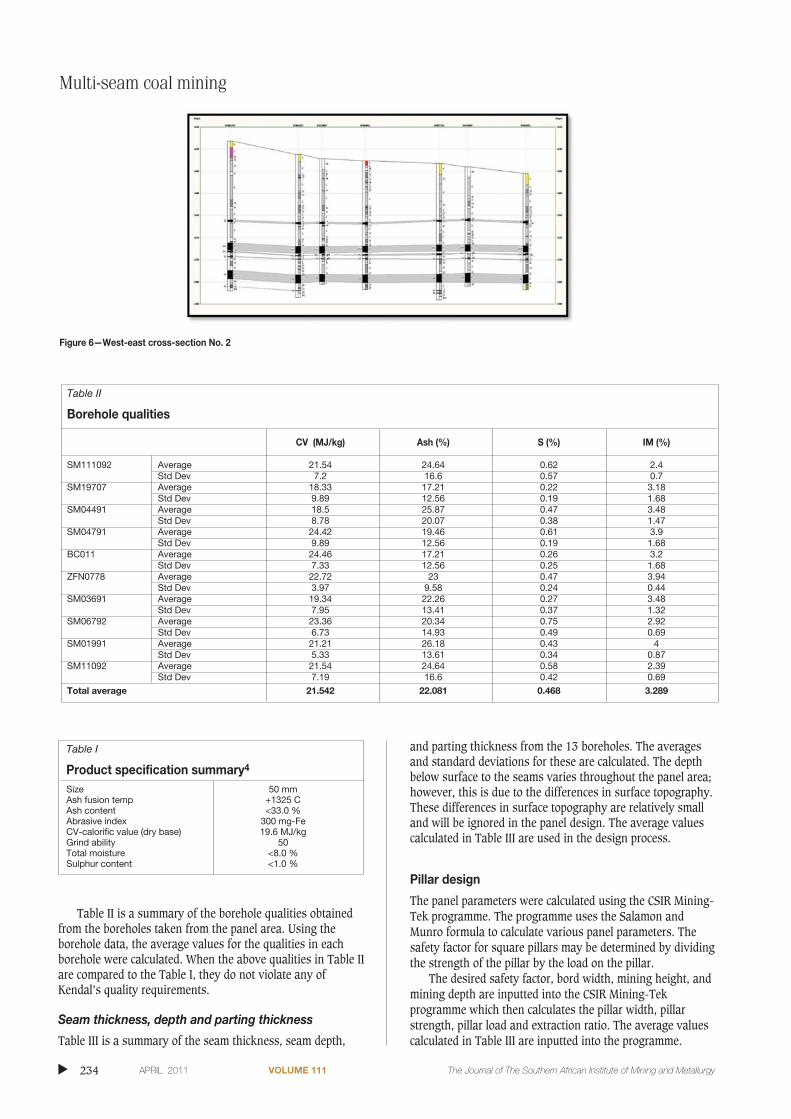
Eskom requires that the coal product sent from KhutalaColliery satisfy Kendal’s specifications. A summary of thespecifications required by Kendal is indicated by Table I.
▲
232 APRIL 2011 VOLUME 111 The Journal of The Southern African Institute of Mining and Metallurgy
Figure 1—Area of investigation
Figure 2—Plan view of panel layout

Multi-seam coal miningJournal
Paper
233The Journal of The Southern African Institute of Mining and Metallurgy VOLUME 111 APRIL 2011 ▲
Figure 3—North-south cross-section No. 1
Figure 4—North-south cross-section No. 2
Figure 5—West-east cross-section No. 1
Multi-seam coal mining
Table II is a summary of the borehole qualities obtainedfrom the boreholes taken from the panel area. Using theborehole data, the average values for the qualities in eachborehole were calculated. When the above qualities in Table IIare compared to the Table I, they do not violate any ofKendal’s quality requirements.
Seam thickness, depth and parting thickness
Table III is a summary of the seam thickness, seam depth,
and parting thickness from the 13 boreholes. The averagesand standard deviations for these are calculated. The depthbelow surface to the seams varies throughout the panel area;however, this is due to the differences in surface topography.These differences in surface topography are relatively smalland will be ignored in the panel design. The average valuescalculated in Table III are used in the design process.
Pillar design
The panel parameters were calculated using the CSIR Mining-Tek programme. The programme uses the Salamon andMunro formula to calculate various panel parameters. Thesafety factor for square pillars may be determined by dividingthe strength of the pillar by the load on the pillar.
The desired safety factor, bord width, mining height, andmining depth are inputted into the CSIR Mining-Tekprogramme which then calculates the pillar width, pillarstrength, pillar load and extraction ratio. The average valuescalculated in Table III are inputted into the programme.
▲
234 APRIL 2011 VOLUME 111 The Journal of The Southern African Institute of Mining and Metallurgy
Figure 6—West-east cross-section No. 2
Table I
Product specification summary4
Size 50 mmAsh fusion temp +1325 CAsh content <33.0 %Abrasive index 300 mg-FeCV-calorific value (dry base) 19.6 MJ/kgGrind ability 50Total moisture <8.0 %Sulphur content <1.0 %
Table II
Borehole qualities
CV (MJ/kg) Ash (%) S (%) IM (%)
SM111092 Average 21.54 24.64 0.62 2.4Std Dev 7.2 16.6 0.57 0.7
SM19707 Average 18.33 17.21 0.22 3.18Std Dev 9.89 12.56 0.19 1.68
SM04491 Average 18.5 25.87 0.47 3.48Std Dev 8.78 20.07 0.38 1.47
SM04791 Average 24.42 19.46 0.61 3.9Std Dev 9.89 12.56 0.19 1.68
BC011 Average 24.46 17.21 0.26 3.2Std Dev 7.33 12.56 0.25 1.68
ZFN0778 Average 22.72 23 0.47 3.94Std Dev 3.97 9.58 0.24 0.44
SM03691 Average 19.34 22.26 0.27 3.48Std Dev 7.95 13.41 0.37 1.32
SM06792 Average 23.36 20.34 0.75 2.92Std Dev 6.73 14.93 0.49 0.69
SM01991 Average 21.21 26.18 0.43 4Std Dev 5.33 13.61 0.34 0.87
SM11092 Average 21.54 24.64 0.58 2.39Std Dev 7.19 16.6 0.42 0.69
Total average 21.542 22.081 0.468 3.289

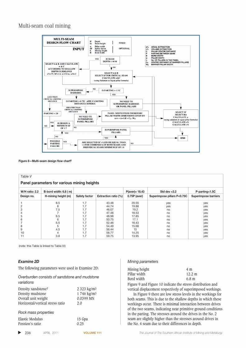
Various panel parameters were calculated for differentmining heights (see Table IV). These panel parameters wereassessed to check for compliance with the Khutala COP ‘Codeof Practice to Combat Rock Falls’. In Khutala’s COP, astandard W/H ratio of 2.2 is used. The bord width at KhutalaColliery also is excavated to a standard width 6.8. Also, theCOP requires that all in panel pillars be designed to safetyfactor of 1.7.5
Panel design parameters:
SF—Safety Factor: 1.7B—Bord width: 6.8 mD—Mining Depth: 100 m
Superimposing multiple seam layouts
Superimposition occurs when the bord and pillar layouts inmultiple seams are developed such that they overlay each ina vertical sequence. The next obvious question is determiningwhether superimposing of pillars will be necessary whendesigning the panel layout.
To assess this, a simplified multi-seam design flowchartwas used in determining whether superimposition would benecessary or not (see Figure 8). This flowchart was used to
assess superimposing of all the various panel parameterscalculated in Table IV (see Table V).
Numerical modelling
Numerical modelling was carried out to back check thevalidity of the multi-seam design guidelines mentionedbefore. Two computer programs used for the modellingprocess were Examine 2D and LaModel. These two modellingprograms were both selected because Examine 2D givesmodel results from a side view perspective wereas theLaModel gives the model results from an aerial viewperspective (plan view). The results from both programs willgive an almost 3-dimensional perspective of the panel areaproviding a richer appreciation of the conditions that areexpected to occur in this new panel.
The panels are modelled under superimposed state andunder a non-superimposed state to compare the conditions.Both the stress distributions and vertical displacements areassessed.
The two different mining heights modelled are the lowestand the mid-high. The average seam height is 7 m thereforethere is little value in modelling a mining height greater thanthis.
Multi-seam coal miningJournal
Paper
The Journal of The Southern African Institute of Mining and Metallurgy VOLUME 111 APRIL 2011 235 ▲
Table IV
Panel parameters calculated using CSIR Mining-Tek
W/H ratio: 2.2 B-Bord width: 6.8Design No. H-Mining height W—pillar width C—centre to centre distance W/H ratio
1 8.5 20.6 27.4 2.422 8 19.7 26.5 2.463 7.5 18.8 25.6 2.514 7 17.9 24.7 2.565 6.5 17 23.8 2.626 6 16 22.8 2.677 5.5 15.1 21.9 2.758 5 14.1 20.9 2.829 4.5 13.2 20 2.9310 4 12.2 19 3.0511 3.8 11.8 18.6 3.11
Table III
Summary of the seam depth, seam thickness and parting thickness
Bhid Depth to No. 4 seam No. 4 seam thickness Depth to No. 2 seam No. 2 seam thickness Parting thickness
BC03681 54.5 6.42 70.5 3.76 9.58BC04181 88.3 7.28 115.42 8.77 19.84BC04281 95.02 5.54 124.54 8.58 23.98BH011 49.75 7.16 74.22 7.39 17.31SM01991 69.2 7.14 95.5 8.04 19.16SM03691 99.88 7.24 126.85 7.73 19.73SM04491 81.74 7.29 107.5 7.27 18.47SM04791 41.92 6.9 68.11 6.59 19.29SM06492 50.32 7.08 73.25 5.69 15.85SM06692 92.23 6.6 119.02 7.89 20.19SM11092 66.16 7.22 91.31 8.14 17.93SM19707 94.22 6.41 118.7 6.82 18.07ZFN0778 91.79 7.02 118.98 8.84 20.17
Average 75 6.87 100.3 7.35 18.43Std dev 20.54 0.51 22.46 1.41 3.27
Multi-seam coal mining
Examine 2D
The following parameters were used in Examine 2D:
Overburden consists of sandstone and mudstonevariations
Density sandstone7 2 323 kg/m3
Density mudstone 1 746 kg/m3
Overall unit weight 0.0399 MNHorizontal/vertical stress ratio 2.0
Rock mass properties
Elastic Modulus 15 GpaPossion’s ratio 0.25
Mining parameters
Mining height 4 mPillar width 12.2 mBord width 6.8 mFigure 9 and Figure 10 indicate the stress distribution andvertical displacement respectively of superimposed workings.
In Figure 9 there are low stress levels in the workings forboth seams. This is due to the shallow depths in which theseworkings occur. There is minimal interaction between drivesof the two seams, indicating near primitive ground conditionsin the parting. The stresses around the drives in the No. 2seam are slightly higher than the stresses around drives inthe No. 4 seam due to their differences in depth.
▲
236 APRIL 2011 VOLUME 111 The Journal of The Southern African Institute of Mining and Metallurgy
Figure 8—Multi-seam design flow chart6
Table V
Panel parameters for various mining heights
W/H ratio: 2.2 B-bord width: 6.8 ( m) P(aver)= 18.43 Std dev =3.2 P-parting<1.5CDesign no. H-mining height (m) Safety factor Extraction ratio (%) 0.75P (aver) Superimpose pillars P<0.75C Superimpose barriers
1 8.5 1.7 43.48 20.55 yes yes2 8 1.7 44.74 19.88 yes yes3 7.5 1.7 46.07 19.2 no yes4 7 1.7 47.48 18.53 no yes5 6.5 1.7 48.98 17.85 no yes6 6 1.7 50.75 17.1 no yes7 5.5 1.7 52.46 16.43 no yes8 5 1.7 54.49 15.68 no yes9 4.5 1.7 56.44 15 no yes10 4 1.7 58.77 14.25 no yes11 3.8 1.7 59.75 13.95 no yes
(note: this Table is linked to Table IV)

Multi-seam coal miningJournal
Paper
The Journal of The Southern African Institute of Mining and Metallurgy VOLUME 111 APRIL 2011 237 ▲Figure 10 indicates low level vertical displacements in
roofs of the drives in both seams. The displacement is tensilein the No. 4 seam roof and in compression in the No. 2 seamroof. Both seams have a compression vertical displacement inthe floor of the drives.
Figure 11 and Figure 12 indicate the stress distributionand vertical displacement respectively of non-superimposedworkings.
In Figure 11 and Figure 10 there are no significantchanges in the conditions when workings are under a non-superimposed state. There are minute increases in stresslevels and vertical displacements that can be ignored. There isminimal interaction between drives of the two seams,indicating near primitive ground conditions in the parting.
Mining Parameters
Mining height 6 mPillar width 16 mBord width 6.8 m
Figure 13 and Figure 14 indicate the stress distributionand vertical displacement respectively of superimposedworkings.
The conditions in Figure 13 and Figure 14 remainrelatively the same as those in Figure 9 and Figure 10. Thereare slight increases in the stress levels and verticaldisplacements; however, nothing significant. In Figure 10,the roof of the No.4 seam drives are in compression ratherthan tension.
Figure 15 and Figure 16 indicate the stress distributionand vertical displacement respectively of non-superimposedworkings.
In Figure 15 and Figure 16 there are again no significantchanges in the conditions when workings are under a non-superimposed state. There are minute increases in stresslevels and vertical displacements that can be ignored. There isminimal interaction between drives of the two seamsindicating near primitive ground conditions in the parting.
Figure 9—Vertical stress in superimposed multiple seam workings
Figure 10—Vertical displacement in superimposed multiple seamworkings
Figure 12—Vertical displacement in non-superimposed multiple seamworkings
Figure 11—Vertical stress distribution in non-superimposed multipleseam workings

LaModel
LaModel was used to model the two seams overlaying eachother. The workings in both seams have the same panelparameters. Only the total vertical stress was analysed onboth seams. This was done for when the panels were
perfectly superimposed and also for different misalignmentpositions when the seams were not superimposed. The panelwere shifted out in 2 m increments. This was done to assesshow the stress conditions in the panel changed withincreasing degree of misalignment.
The following parameters were used in the LaModel:Mining height 6 mPillar width 16 mBord width 6.8 mEseam 4 GpaEoverburden 15 GpaFigure 17 and Figure 18 indicate the total vertical stress
on the No. 2 seam and No. 4 seam workings respectivelyunder superimposed conditions.
In Figure 17, the total vertical stress values are relativlylow. The greatest amount of vertical stress is towards thecentre of the panels. The lower stress values area locatedaround the edges of the panel.
In Figure 18, the stress values remain relatively low;however, there is a slight increase in stress levels due to itsgreater depth. The greater stress levels are still found towardsthe centre of the new panel, with lowest values locatedtowards the edges.
Multi-seam coal mining
▲
238 APRIL 2011 VOLUME 111 The Journal of The Southern African Institute of Mining and Metallurgy
Figure 16—Vertical displacement in non-superimposed multiple seamworkings
Figure 17—Total vertical stress on superimposed No. 4 seam workings
Figure 13—Vertical stress distribution in superimposed multiple seamworkings
Figure 14—Vertical displacements in superimposed multiple seamworkings
Figure 15—Vertical stress distribution in non-superimposed multipleseam workings
Multi-seam coal miningJournal
Paper
The Journal of The Southern African Institute of Mining and Metallurgy VOLUME 111 APRIL 2011 239 ▲
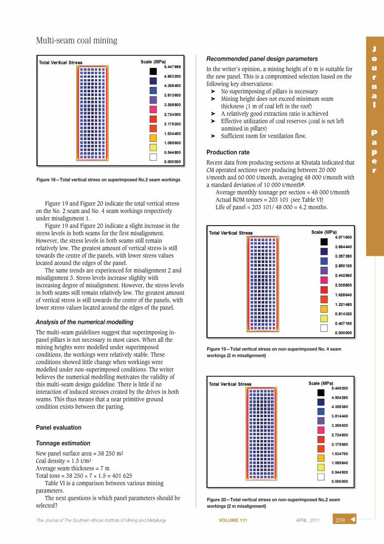
Figure 19 and Figure 20 indicate the total vertical stresson the No. 2 seam and No. 4 seam workings respectivelyunder misalignment 1.
Figure 19 and Figure 20 indicate a slight increase in thestress levels in both seams for the first misalignment.However, the stress levels in both seams still remainrelatively low. The greatest amount of vertical stress is stilltowards the centre of the panels, with lower stress valueslocated around the edges of the panel.
The same trends are experienced for misalignment 2 andmisalignment 3. Stress levels increase slighlty withincreasing degree of misalignment. However, the stress levelsin both seams still remain relatively low. The greatest amountof vertical stress is still towards the centre of the panels, withlower stress values located around the edges of the panel.
Analysis of the numerical modelling
The multi-seam guidelines suggest that superimposing in-panel pillars is not necessary in most cases. When all themining heights were modelled under superimposedconditions, the workings were relatively stable. Theseconditions showed little change when workings weremodelled under non-superimposed conditions. The writerbelieves the numerical modelling motivates the validity ofthis multi-seam design guideline. There is little if nointeraction of induced stresses created by the drives in bothseams. This thus means that a near primitive groundcondition exists between the parting.
Panel evaluation
Tonnage estimation
New panel surface area = 38 250 m2
Coal density = 1.5 t/m3
Average seam thickness = 7 mTotal tons = 38 250 × 7 × 1.5 = 401 625
Table VI is a comparison between various miningparameters.
The next questions is which panel parameters should beselected?
Recommended panel design parameters
In the writer’s opinion, a mining height of 6 m is suitable forthe new panel. This is a compromised selection based on thefollowing key observations:
➤ No superimposing of pillars is necessary➤ Mining height does not exceed minimum seam
thickness (1 m of coal left in the roof)➤ A relatively good extraction ratio is achieved➤ Effective utilization of coal reserves (coal is not left
unmined in pillars)➤ Sufficient room for ventilation flow.
Production rate
Recent data from producing sections at Khutala indicated thatCM operated sections were producing between 20 000t/month and 60 000 t/month, averaging 48 000 t/month witha standard deviation of 10 000 t/month8.
Average monthly tonnage per section = 48 000 t/monthActual ROM tonnes = 203 101 (see Table VI)Life of panel = 203 101/ 48 000 = 4.2 months.
Figure 18—Total vertical stress on superimposed No.2 seam workings
Figure 20—Total vertical stress on non-superimposed No.2 seamworkings (2 m misalignment)
Figure 19—Total vertical stress on non-superimposed No. 4 seamworkings (2 m misalignment)

Infrastructure
Infrastructure that has to be excavated for mining operationsto be carried out include:
➤ Workshops➤ Refuge bays➤ Sub-stations ➤ Airway crossings/crossover.
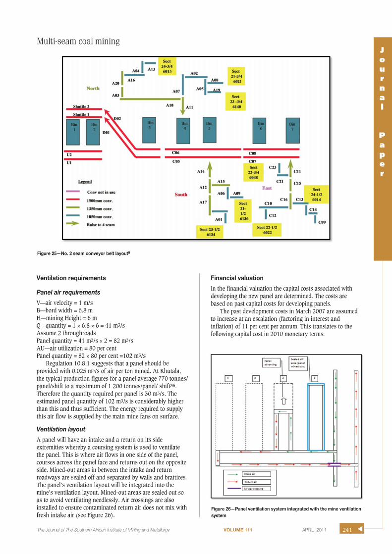
Improving men, material and product flow
Strategy: installation of a new storage bunker system for No. 2seam. A bunker system is proposed to be installed along themain conveyor belt of the southern workings (see Figure 25).
Advantages of new surge bin installation
➤ Continuous production from production panels despitebreakdowns on the main belts
➤ Access from #2 seam to #4 seam➤ Improves supply of services ➤ Provides ventilation flexibility.
Problems to be expected:
➤ High construction and infrastructural costs(R12 000 000).
➤ Installation process will result in deviations from thedesigned mine layout.
Multi-seam coal mining
▲
240 APRIL 2011 VOLUME 111 The Journal of The Southern African Institute of Mining and Metallurgy
Table VI
Extraction ratios and coal reserves to be extracted for different mining heights
Mining height (m) Extraction ratio (%) Total tonnes in panel area (t) Actual tonnes extracted (t)
4 58.77 401 625 236 0356 50.57 401 625 203 1018 44.74 401 625 179 687
Figure 22—Total vertical stress on non-superimposed No. 2 seamworkings (4 m misalignment)
Figure 21—Total vertical stress on non-superimposed No. 4 seamworkings (4 m misalignment)
Figure 24—Total vertical stress on non-superimposed No. 2 seamworkings (6 m misalignment)
Figure 23—Total vertical stress on non-superimposed No. 4 seamworkings (6 m misalignment)
Multi-seam coal miningJournal
Paper
The Journal of The Southern African Institute of Mining and Metallurgy VOLUME 111 APRIL 2011 241 ▲
Figure 25—No. 2 seam conveyor belt layout9
Ventilation requirements
Panel air requirements
V—air velocity = 1 m/sB—bord width = 6.8 mH—mining Height = 6 mQ—quantity = 1 × 6.8 × 6 = 41 m3/sAssume 2 throughroads Panel quantity = 41 m3/s × 2 = 82 m3/sAU—air utilization = 80 per centPanel quantity = 82 × 80 per cent =102 m3/s
Regulation 10.8.1 suggests that a panel should beprovided with 0.025 m3/s of air per ton mined. At Khutala,the typical production figures for a panel average 770 tonnes/panel/shift to a maximum of 1 200 tonnes/panel/ shift35.Therefore the quantity required per panel is 30 m3/s. Theestimated panel quantity of 102 m3/s is considerably higherthan this and thus sufficient. The energy required to supplythis air flow is supplied by the main mine fans on surface.
Ventilation layout
A panel will have an intake and a return on its sideextremities whereby a coursing system is used to ventilatethe panel. This is where air flows in one side of the panel,courses across the panel face and returns out on the oppositeside. Mined-out areas in between the intake and returnroadways are sealed off and separated by walls and brattices.The panel’s ventilation layout will be integrated into themine’s ventilation layout. Mined-out areas are sealed out soas to avoid ventilating needlessly. Air crossings are alsoinstalled to ensure contaminated return air does not mix withfresh intake air (see Figure 26).
Financial valuation
In the financial valuation the capital costs associated withdeveloping the new panel are determined. The costs arebased on past capital costs for developing panels.
The past development costs in March 2007 are assumedto increase at an escalation (factoring in interest andinflation) of 11 per cent per annum. This translates to thefollowing capital cost in 2010 monetary terms:
Figure 26—Panel ventilation system integrated with the mine ventilationsystem

Multi-seam coal mining
Interest: 6.50 per centInflation: 4.20 per centEscalation = (1+0.065) (1+0.042) – 1
= 10.9 per cent, say 11 per cent
Tables VII to Table X indicate the capital requirements forthe new panel.
Comments (findings)
The design that goes into developing a new panel requiresprior knowledge from various departments such as rockengineering, planning, geology, mining, and ventilation. Allthe concepts from these departments must be integrated toform a coherent panel design. The panel design must done inline with the existing mine design. It must be aimed atextracting as much of the reserve as possible. The overalldesign must ensure that production begins in a safe andeconomical way.
References
1. BHP BILLITON. Health, Safety, Environment and Community (HSEC).
Khutala Colliery Mining Department, Internal and Unpublished Article.
Republic of South Africa, 2004. p. 2.
2. FAUCONNIER, C.J., and KERSTEN, R.W.O. Iincreased underground extraction of
coal. The Southern African Institute of Mining and Metallurgy.
Johannesburg, 1982, pp. 23–26.
3. CLARK, J. and CALDON, J.H. Thin seam coal mining technology. Noyes Data
Corporation. p. 63.
4. BHP BILLITON. Health, Safety, Environment and Community (HSEC).
Khutala Colliery Mining Department, Internal and unpublished article.
Republic of South Africa, 2004. p. 6.
5. BHP BILLITON. COP to Combat Rockfalls Accidents in Underground Coal
Mines (COP/OH/001). Khutala Colliery Mining Department, Internal and
unpublished article. Republic of South Africa.
6. VAN DER MERWE, J.N. and MADDEN, B.J. Rock engineering for underground
coal mining. Safety in Mines Research Advisory Committee and the
Southern African Institute of Mining and Metallurgy. p 101.
7. ANONYMOUS. density of materials. http://www.simetric.co.uk/
si_materials.htm. Accessed 10th July.
8. BHP BILLITON. No. 2 seam production figures. Excel file. Khutala Colliery
Mining Department, Internal and Unpublished Article. Republic of South
Africa.
9. BHP BILLITON. No. 2 seam Conveyor belt layout. Khutala Colliery Mining
Department, Internal and Unpublished Article. Republic of South Africa.
10. BHP BILLITON. Development Capital. Khutala Colliery Mining Department,
Internal and Unpublished Article. Republic of South Africa. ◆
▲
242 APRIL 2011 VOLUME 111 The Journal of The Southern African Institute of Mining and Metallurgy
Table IX
Replacement capital escalated at 11%10
Section transport 547 052.40
Toro and tractor 6 496 247.25
Maintenance car 1 094 104.80
Stone duster 2 188 209.60
Total replacement capital 10 325 614.05
Table X
Total costs
Total development capital 19 420 360.20
Total major overhaul 18 535 152.80
Total replacement capital 10 325 614.05
Total panel cost R 48 281 127.05
Table VII
Development capital escalated at 11%10
Conveyor equipment purchase
1050 Drive 1 367 631.00
1050 Tail end 136 763.10
General equipment 547 052.40
General equipment 547 052.40
Belt transformer 1 025 723.25
Flitting panels 547 052.40
Starter panels 547 052.40
Transformer 2 051 446.50
Trailing cables R 547 052.40
Switches 1 641 157.20
Mobile sub 1 367 631.00
Conveyor and structure 683 815.50
Electrical equipment
Belt transformer 1 025 723.25
Flitting panels 547 052.40
Starter panels 547 052.40
Transformer 2 051 446.50
Trailing cables 547 052.40
Switches 1 641 157.20
Mobile sub 1 367 631.00
Conveyor and structure 683 815.50
Total development capital 19 420 360.20
Table VIII
Mining equipment major overhaul escalated 11%10
Extra Section Mach - CM No.18 12 035 152.80
2#Shuttle Car No.29 (New Sect) 1 500 000.00
2#Shuttle Car No.37 (New Sect.) 1 500 000.00
2#Shuttle Car No.38 (New Sect.) 1 500 000.00
2#Feeder Breaker (New Sect.) 1 200 000.00
2#Roof bolter (New Sect.) 800 000.00
Total major overhaul 18 535 152.80