multi-scale modeling of solid state electrolytes for next
TRANSCRIPT

P.I.: A. Ngo, L. Curtiss, V. SrinivasanArgonne National Laboratory
DOE merit reviewJune 21-25, 2021
This presentation does not contain any proprietary, confidential, or otherwise restricted information.
Multi-scale Modeling of Solid StateElectrolytes for Next Generation Lithium
Batteries
Project ID# bat424

2
§ Start: 2020§ Finish: 2022§ Completed: 50 %
§ Barriers addressed– Low Conductivity– High interfacial impedance– Dendrite growth
• Total project funding– DOE share: $ 1.295 M– Contractor 0
• FY 20: $395 K• FY 21: $ 450 K• FY 22: $ 450 K
Timeline
Budget
Barriers
• Interactions/ collaborations• Pallab Brai, ANL• Z. Chen, ANL• B. Narayanan, U of Louisville
Partners
Overview

3
Project Objectives and Relevance§ In order to improve the safety of present day lithium ion
batteries, replacement of liquid electrolytes with their solid state counterparts is a necessity.
§ Multi-scale modelling efforts have been adopted to obtain an in-depth understanding of the interaction between the electrode and the solid electrolyte aimed at developing highly efficient solid state electrolytes batteries.
§ Properties estimated from DFT calculations are fed into the mesoscale models, that analyze overall stability of solid electrolytes against cathodes and anodes.
§ Solid state electrolytes with lithium metal anode and cathode have the potential to substantially increase the energy density of present day lithium ion batteries.

4
FY21 MilestonesMonth/Year Milestones
Dec/20 Determine stable surface of the Li6PS5Cl SSE and the NMC-811/Li6PS5Cl interface. (Q1, FY 2021; Completed)
Mar/21 Conduct AIMD study of electrochemical interface between NMC-811/Li6PS5Cl. (Q2, FY 2021; Completed)
Jun/21 Investigate Li-ion transport of the NMC-811/Li6PS5Cl interface, and calculate exchange current density. (Q3, FY 2021; Initiated)
Sep/21Incorporate information obtained from the atomistic calculations into the mesoscale model, and predict the impact on performance. (Q4, FY 2021; Initiated)

Strategy: A multiscale approach has been adopted, where transport and elastic properties of lithium and solid state electrolytes have been computed at the nanoscale using DFT
calculations, and then the properties have been transferred to the continuum scale model where the mesoscale electrode electrolyte behavior has been analyzed.
10˚ms
100˚ns
10˚mm
˚
˚nm 100˚nm
ps• Surface and Interfacial energy• Li migration barriers.• Ab initio molecular dynamic.
Charge transfer.• Li concentration at interface
DFT calculations
Mesoscale
• Ion conductivity• Bulk and Grain Boundary• Young’s modulus• exchange current density• Fractures.
• Growth of interphases (e.g., dendrite propagation)
• Stress distribution
Length
TimeMulti-Scale Modeling methods
Atomistic - MD, MC
6
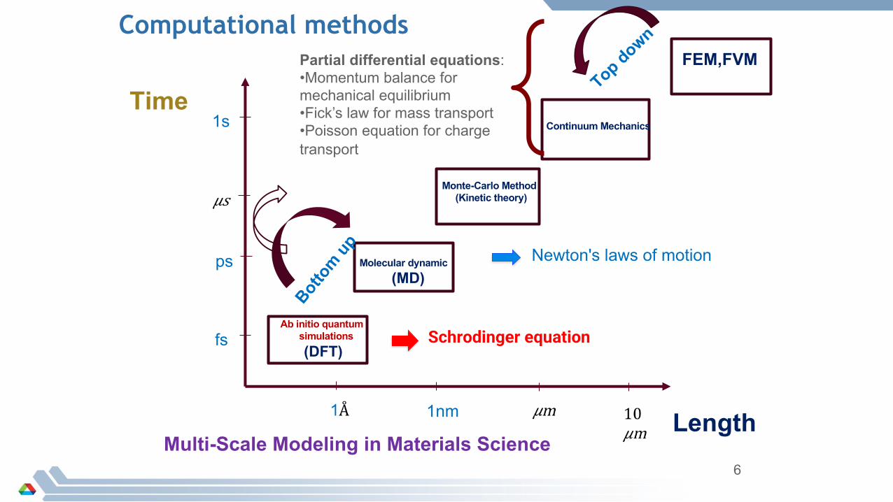
Computational methods
fs
ps
1s
1nm
Molecular dynamic(MD)
Monte-Carlo Method(Kinetic theory)
Continuum Mechanics
Length
Time
Botto
m up
Top down
Multi-Scale Modeling in Materials Science
(DFT)
FEM,FVM
Schrodinger equation
Newton's laws of motion
Ab initio quantum simulations
Partial differential equations:•Momentum balance for mechanical equilibrium•Fick’s law for mass transport•Poisson equation for charge transport
7
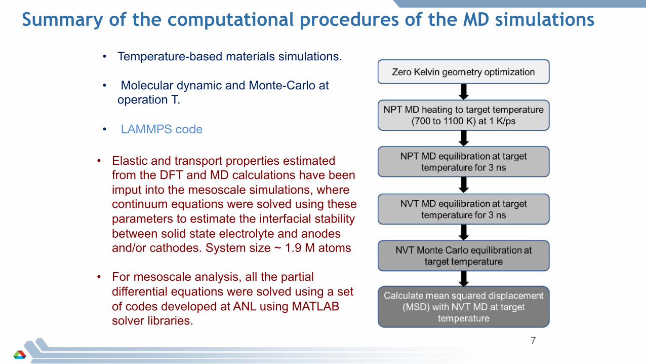
Summary of the computational procedures of the MD simulations
• Temperature-based materials simulations.
• Molecular dynamic and Monte-Carlo at operation T.
• LAMMPS code
• Elastic and transport properties estimated from the DFT and MD calculations have been imput into the mesoscale simulations, where continuum equations were solved using these parameters to estimate the interfacial stability between solid state electrolyte and anodes and/or cathodes. System size ~ 1.9 M atoms
• For mesoscale analysis, all the partial differential equations were solved using a set of codes developed at ANL using MATLAB solver libraries.
8
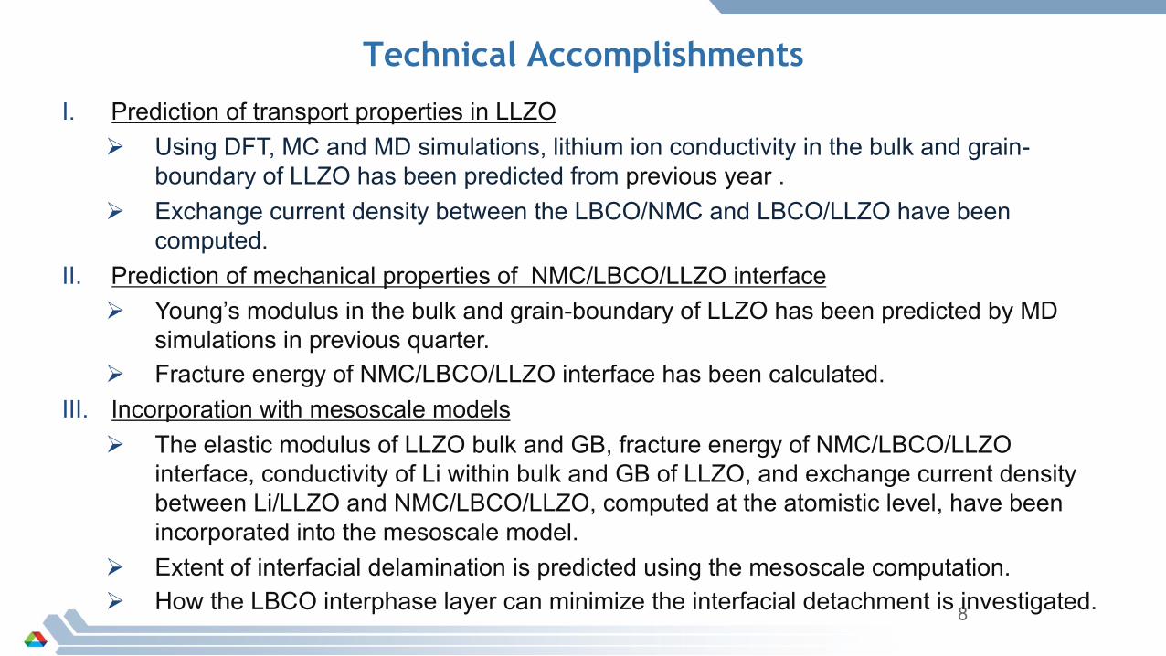
Technical Accomplishments
I. Prediction of transport properties in LLZOØ Using DFT, MC and MD simulations, lithium ion conductivity in the bulk and grain-
boundary of LLZO has been predicted from previous year .Ø Exchange current density between the LBCO/NMC and LBCO/LLZO have been
computed.II. Prediction of mechanical properties of NMC/LBCO/LLZO interface
Ø Young’s modulus in the bulk and grain-boundary of LLZO has been predicted by MD simulations in previous quarter.
Ø Fracture energy of NMC/LBCO/LLZO interface has been calculated.III. Incorporation with mesoscale models
Ø The elastic modulus of LLZO bulk and GB, fracture energy of NMC/LBCO/LLZO interface, conductivity of Li within bulk and GB of LLZO, and exchange current density between Li/LLZO and NMC/LBCO/LLZO, computed at the atomistic level, have been incorporated into the mesoscale model.
Ø Extent of interfacial delamination is predicted using the mesoscale computation.Ø How the LBCO interphase layer can minimize the interfacial detachment is investigated.
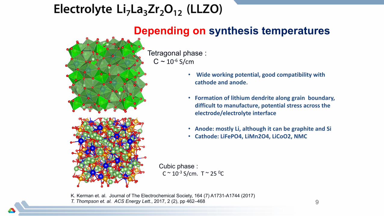
Depending on synthesis temperatures
Tetragonal phase :C ~ 10-6 S/cm
Cubic phase :C ~ 10-3 S/cm. T ~ 25 0C
• Wide working potential, good compatibility with cathode and anode.
• Formation of lithium dendrite along grain boundary, difficult to manufacture, potential stress across the electrode/electrolyte interface
• Anode: mostly Li, although it can be graphite and Si• Cathode: LiFePO4, LiMn2O4, LiCoO2, NMC
K. Kerman et. al. Journal of The Electrochemical Society, 164 (7) A1731-A1744 (2017)T. Thompson et. al. ACS Energy Lett., 2017, 2 (2), pp 462–468 9
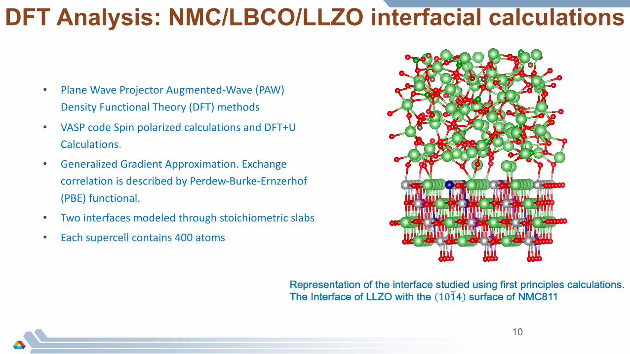
DFT Analysis: NMC/LBCO/LLZO interfacial calculations
• Plane Wave Projector Augmented-Wave (PAW) Density Functional Theory (DFT) methods
• VASP code Spin polarized calculations and DFT+U Calculations.
• Generalized Gradient Approximation. Exchange correlation is described by Perdew-Burke-Ernzerhof (PBE) functional.
• Two interfaces modeled through stoichiometric slabs
• Each supercell contains 400 atoms
10
11
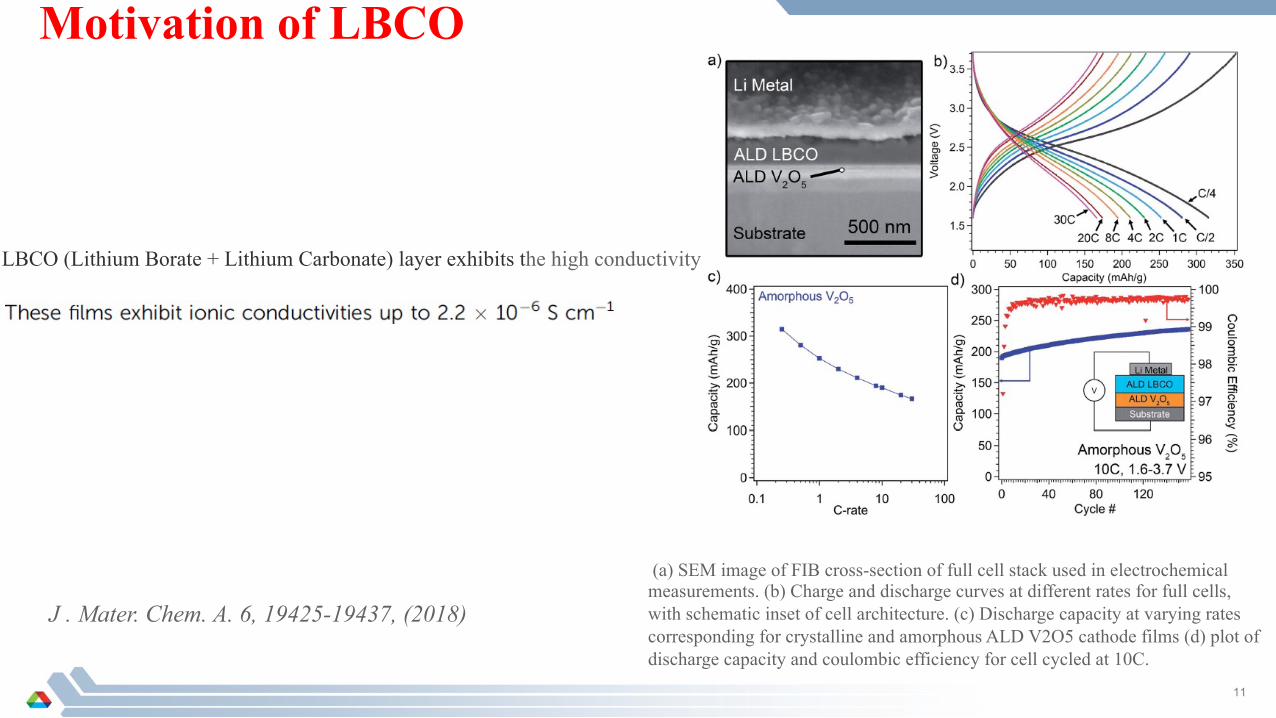
Motivation of LBCO
J . Mater. Chem. A. 6, 19425-19437, (2018)
LBCO (Lithium Borate + Lithium Carbonate) layer exhibits the high conductivity
(a) SEM image of FIB cross-section of full cell stack used in electrochemical measurements. (b) Charge and discharge curves at different rates for full cells, with schematic inset of cell architecture. (c) Discharge capacity at varying rates corresponding for crystalline and amorphous ALD V2O5 cathode films (d) plot of discharge capacity and coulombic efficiency for cell cycled at 10C.

12
Two interface system
LLZO-LBCO interface
NM
C C
atho
de
Inte
rpha
se L
ayer
LLZO
ele
ctro
lyte
Interface: I Interface: IILBCO (Li3BO3-Li2CO3)
When a cathode is coated, the cathode/SSEinterface is replaced by two new interfaces: the cathode/ coating interface and the coating/SSE interface
Interphase Layer LBCONMC-LBCO interface

13
-0.1
0.0
0.1
0.2
0.3
0.4
0.5
0.6
0.7
DE(eV) 0.68 eV
Non-exothermic reaction
LLZO-LBCO interface : Li migration barrier at interface
Li migration at the LLZO-LBCO interface Migration barrier : 0.68 eV

0.57 eV
Exothermic reaction
14
NMC-LBCO interface : Li migration barrier at interface
Li migration at the NMC-LBCO interface Migration barrier : 0.57 eV
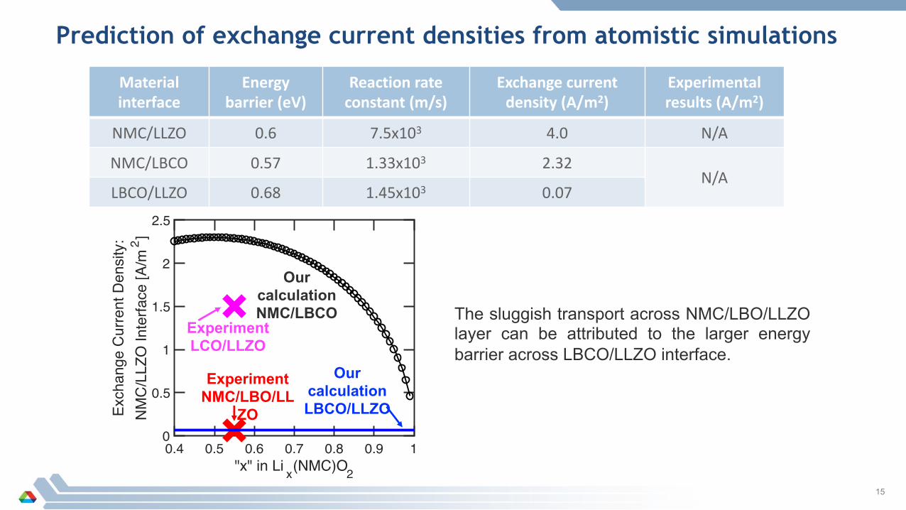
Prediction of exchange current densities from atomistic simulations
15
Material interface
Energy barrier (eV)
Reaction rate constant (m/s)
Exchange current density (A/m2)
Experimental results (A/m2)
NMC/LLZO 0.6 7.5x10³ 4.0 N/A
NMC/LBCO 0.57 1.33x10³ 2.32N/A
LBCO/LLZO 0.68 1.45x10³ 0.07
The sluggish transport across NMC/LBO/LLZOlayer can be attributed to the larger energybarrier across LBCO/LLZO interface.
0.4 0.5 0.6 0.7 0.8 0.9 1"x" in Li x(NMC)O2
0
0.5
1
1.5
2
2.5
Exch
ange
Cur
rent
Den
sity
:N
MC
/LLZ
O In
terfa
ce [A
/m2 ]
Our calculation NMC/LBCO
Our calculation LBCO/LLZO
Experiment NMC/LBO/LL
ZO
Experiment LCO/LLZO

Fracture energy 6.5 J/m2
Barrier 0.57 eV
Fracture energy 3.8 J/m2
Barrier 0.67eV Approximate delamination: 40% Approximate delamination: 20%
Interphase Layer LBCO
Impact of the LBCO Layer on the delaminationNMC/LLZO interface has the delamination: 75%

LBCO interphase layers to minimize cathode/LLZO delamination
17
Interphase layer: LBCO (Lithium Borate + Lithium Carbonate)
CC-CV Charge and CC Discharge
Iapp = 1A/m2 Voltage window: 3.0V – 4.5V
NMC Cathode
Grain InteriorGrain
Boundary
Interphase Layer
Thickness~5nm
LBCO interphase layers help to mitigate interfacial delamination and subsequent capacity fade.
0 50 100 150 200Capacity [mAh/g]
3
3.2
3.4
3.6
3.8
4
4.2
4.4
4.6
Volta
ge [V
]
No interphase layer
tLBCO ~ 5nm
After Discharge tLBCO =0
Interfacial Delamination

18
Impact of LBCO Layer Thickness on Capacity and Extent of Delamination
LBCO interphase layer thickness varied between 5 nm and 25 nm.
Iapp = 1A/m2
0 5 10 15 20 25 30Interphase LBCO Layer Thickness [nm]
0
20
40
60
80
100
Dela
min
atio
n [%
]
Extent of delamination is minimized with
LBCO layer
0 5 10 15 20 25 30Interphase LBCO Layer Thickness [nm]
150
155
160
165
170
175
180
Disc
harg
e Ca
pacit
y [m
Ah/g
]
Addition of LBCO interphase suppress
capacity fade
Ohmic potential drop causes extra first cycle capacity fade for thicker LBCO.LBCO interphase layers help to mitigate interfacial delamination

19
Influence of Multiple Cycles on the Delamination Induced Capacity Fade
CC-CV Charge and CC Discharge
Iapp = 1A/m2 Voltage window: 3.2V – 4.5V
Capacity fade observed in two steps:1. Large capacity fade in the first cycle2. Slow capacity fade later
LBCO interphase layer can mitigate the initial capacity fade as well as the slow
capacity decay for longer cycles.0 2 4 6 8 10# of Cycles
140
150
160
170
180
190D
isch
arge
Cap
acity
[mAh
/g]
tLBCO ~ 5nm
tLBCO ~ 25nm
No Interphase Layer

20
Influence of LBCO Layer in Capacity Retention at Higher Current Densities
CC-CV Charge and CC Discharge
Voltage window: 3.2V – 4.5V
Two possibility behind lower capacity at higher currents:1. Enhanced delamination induced fade2. Higher ohmic drop from small conductivity of LBCO
Lower conductivity of LBCO is a challenge.
Better interphase layers with higher conductivity needs to be designed.
0 2 4 6 8 10Applied Current Density (Iapp) [A/m2]
0
0.2
0.4
0.6
0.8
1
Frac
tiona
l Del
amin
atio
n
tLBCO ~ 5nm25nm
No Interphase Layer
First cycle discharge capacity
0 2 4 6 8 10Applied Current Density (Iapp) [A/m2]
0
50
100
150
200
Dis
char
ge C
apac
ity [m
Ah/g
]
tLBCO ~ 5nm
tLBCO ~ 25nm
No Interphase Layer
Conductivity
Response to last year reviewer’s comments
No comments from last year.
21
22
§ Estimation of lithium transport barrier at the Li6PS5Cl SSE and the NMC-811/Li6PS5Cl interface : – Effective exchange current density will be estimated at NMC/ and
Li6PS5Cl SSE interface– Interfacial formation/Binding energy between the NMC cathode with
Li6PS5Cl SSE will be calculated§ Estimation of the extent of interfacial delamination between NMC and
Li6PS5Cl solid electrolytes.§ Application of interphase layers in minimizing the delamination between
NMC cathodes and soft sulfide-based electrolytes.§ Interdiffusion of transition metal ions between cathode and solid-
electrolyte and formation of a passivating interphase layer, which is more prominent for sulfide based solid-electrolytes.
Proposed Future Work
23
§ Incorporate the parameters estimated from atomistic calculations into the continuum level mesoscale model– Predict the effect of grain boundary resistance on the overall voltage-capacity
performance– Estimate the impact the delamination and inter-granular fracture on the overall
impedance behavior.
§ Investigate the impact of interfacial layer on the possibility of minimizing the interfacial delamination between the cathode and solid-electrolytes.
Proposed Future Work (cont.)

Collaborations with other institutions and companies
• V. Srinivasan, P. Barai, ANL• Development of continuum based mesoscale models for running
simulations using the parameters obtained from atomistic analysis.
• Z. Chen, ANL• Experimental characterization of electrode-electrolyte interface
• B. Narayanan, U of Louisville • Discussions regarding the atomistic analysis conducted at ANL to
estimate elastic and transport properties of LLZO.
24

25
Summary
Ø Atomistic level calculations were used to obtain parameters, DFT, ab initio MD, atomistic MD and MC needed for accurate mesoscale modeling of LLZO grain-interior, grain-boundary, and LLZO/LBCO/NMC cathode interfaces .
Ø Interfacial and mechanical degradation mechanisms were investigated at the atomistic level to develop a strategy for minimizing impact on performance.
Ø Incorporation of LBCO interphase layers between NMC and LLZO can help to minimize the extent of delamination and subsequent capacity fade.
Ø Lower ionic conductivity of LBCO is a challenge in obtaining good performance at higher current densities. Design of better interphase layers with higher ionic conductivities is necessary for successful application in solid-state lithium-ion batteries.