multi radio channel replicator (air interface) bringing ... · multi-radio channel replicator (air...
TRANSCRIPT

1
Product
Summary
Multi-Radio Channel Replicator (Air Interface)
Bringing the Test Range to Your Test Bench
Introduction
The Eastern OptX Series 7000 System is
a multi-radio test network which replicates
the propagation path of real-world appli-
cations. The system allows the user to
test a variety of Air Interfaces using the
same system without modification and at
the same time. This is not a signal emula-
tor. The systems use low-loss fiber optic
cable to create the propagation delay as-
sociated with radio transmissions from 1
to 5000 MHz. Multiple radios may be con-
nected to the network which allows for full
duplex operation. Each radio may operate
using a different or identical Air Interface.
The delays between radios may be fixed
or variable and optional amplitude control
provides the appropriate propagation
loss. The Series 7000 creates a test
range right in your lab. It can be used as
a design aid and as a test tool for new
modulation and encryption schemes prior
to expensive field testing.
Standard System Features
2 –10 Radio Ports
Radio to Radio distances from 1 to
50,000 m.
Delay Configurations: Discrete, Pro-
gressive, or Combined Discrete and
Progressive.
Multipath Replicator Option
Amplitude Control — Optical and/or RF
Remote Control Interface
Front Panel LCD Touch Screen Control
External Delay Option for Future Expan-
sion
Octave Input Bandwidth (Multi-Octave
systems available with automatic input
frequency selector)
Single or Multiple Air Interfaces may be
tested simultaneously.
Doppler Option (Moving Target)
Interferer Injection (Jammer)
Eastern OptX, Inc. A Veteran Owned Small Business
710 E. Main Street ∙ Moorestown, NJ 08057 ∙ 877 870 6789 (toll free) ∙ 856-231-9022 (fax)
www.eastern-optx.com ∙ [email protected]
FORM-0011 REV3

2
System Description
A simple, two-radio system with a 600 micro-
second delay is shown in Figure 1. The system
consists of two bi-directional optical modula-
tor / demodulator and a fiber optic dely. The
delay may be fixed or variable and a variable
attenuator may be added to replicate propaga-
tion loss. A radio is connected to ether end of
the system and may transmit and receive sim-
ultaneously. Figure 2 shows the modulator /
demodulator detail. The optical system is
broad band (up to 18 GHz). The system band-
width is limited by the input circulator (Typically
1 octave)
Multi-Radio Channel Replicator
Bi-Directional Optical Modulator/De-
Modulator
Laser
Modulator
Optical De-
Modulator
Radio I/O Optical
Input/Output
Figure 2.
B
600 us
B
Bi-Directional Optical
Modulator/Demodulator
B
B
Radio 1
Radio 2 Figure 1. Two-Radio
System Block Diagram
Eastern OptX, Inc. A Veteran Owned Small Business
710 E. Main Street ∙ Moorestown, NJ 08057 ∙ 877 870 6789 (toll free) ∙ 856-231-9022 (fax)
www.eastern-optx.com ∙ [email protected]
FORM-0011 REV3

3
Options
Frequency Bands * (3dB bandwidth):
1. 225 - 450 MHz
2. 960 - 1215 MHz
3. 1350 - 1850 MHz
* Input RF Circulator BW. System BW: 0.1 to 3 GHz.
Optical bandwidths are available up from 0.1 to 18 GHz. The RF input is lim-
ited to octave bandwidths by the input circulator. Eastern OptX offers a tri-
band input circulator (Part Number 535B) which automatically detects and
selects the proper input circulator to cover the input frequency range from
225 to 1850 MHz.
Variable delays with Discrete or Progres-
sive configurations (See Page 4)
Multipath Option (Multipath channels may
be added )
Star and Series Node Connections (See
page 6)
Propagation Loss Option
Google Maps Radio Location Entry
Multi-Radio Channel Replicator
Eastern OptX, Inc. A Veteran Owned Small Business
710 E. Main Street ∙ Moorestown, NJ 08057 ∙ 877 870 6789 (toll free) ∙ 856-231-9022 (fax)
www.eastern-optx.com ∙ [email protected]
FORM-0011 REV3
4
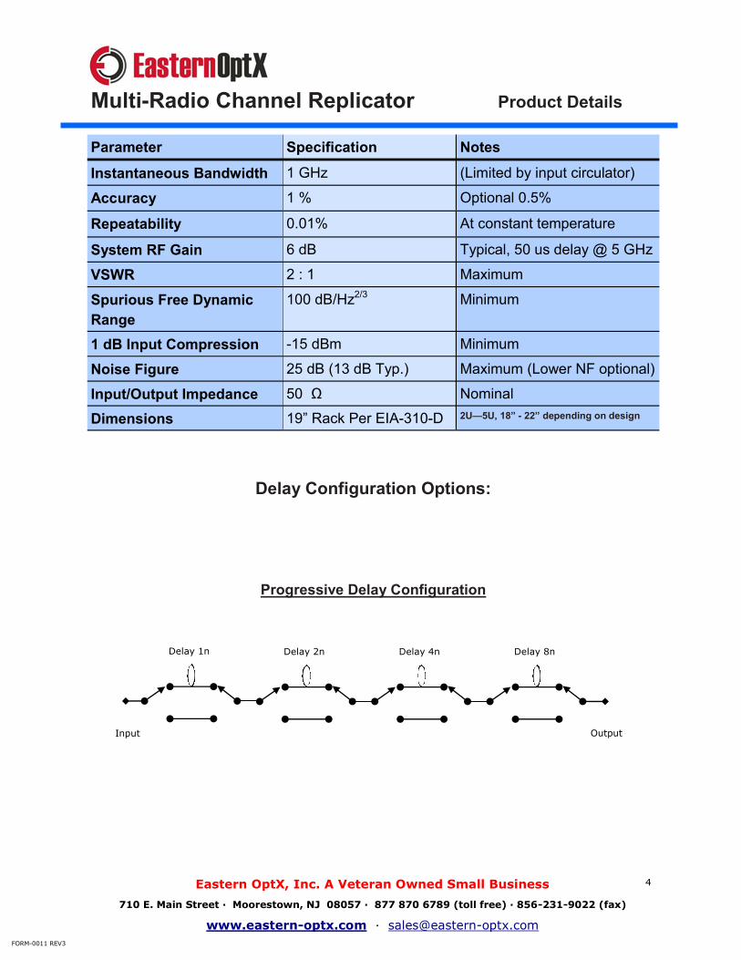
Product Details
Parameter Specification Notes
Instantaneous Bandwidth 1 GHz (Limited by input circulator)
Accuracy 1 % Optional 0.5%
Repeatability 0.01% At constant temperature
System RF Gain 6 dB Typical, 50 us delay @ 5 GHz
VSWR 2 : 1 Maximum
Spurious Free Dynamic
Range
100 dB/Hz2/3
Minimum
1 dB Input Compression -15 dBm Minimum
Noise Figure 25 dB (13 dB Typ.) Maximum (Lower NF optional)
Input/Output Impedance 50 Ω Nominal
Dimensions 19” Rack Per EIA-310-D 2U—5U, 18” - 22” depending on design
Delay Configuration Options:
Progressive Delay Configuration
Delay 1n Delay 2n Delay 4n Delay 8n
Input Output
Multi-Radio Channel Replicator
Eastern OptX, Inc. A Veteran Owned Small Business
710 E. Main Street ∙ Moorestown, NJ 08057 ∙ 877 870 6789 (toll free) ∙ 856-231-9022 (fax)
www.eastern-optx.com ∙ [email protected]
FORM-0011 REV3
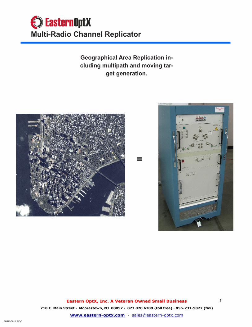
5
Geographical Area Replication in-
cluding multipath and moving tar-
get generation.
Multi-Radio Channel Replicator
Eastern OptX, Inc. A Veteran Owned Small Business
710 E. Main Street ∙ Moorestown, NJ 08057 ∙ 877 870 6789 (toll free) ∙ 856-231-9022 (fax)
www.eastern-optx.com ∙ [email protected]
FORM-0011 REV3
=

6
Discrete Delay Configuration
Delay 2
Delay 1
Delay 3
Delay n
Output Input
Progressive:
Best solution for equally spaced de-lay step sizes
Numerous possible delay combina-tions (Binary: 1, 2, 4, 8 etc.)
More delays in a smaller package
1% overall accuracy.
Discrete:
Best solution for few delays or une-qual delay steps sizes.
One to eight delays typical
Better than 0.1% accuracy possible.
Multi-Radio Channel Replicator
Eastern OptX, Inc. A Veteran Owned Small Business
710 E. Main Street ∙ Moorestown, NJ 08057 ∙ 877 870 6789 (toll free) ∙ 856-231-9022 (fax)
www.eastern-optx.com ∙ [email protected]
FORM-0011 REV3

7
Multi-Radio Channel Replicator
4 Radio Modified Star Node Air Interface Tester
B
B
B B
Radio 4
Radio 3
Radio 2
Radio 1
B
1x3 Optical
Splitter-
Combiner Bi-
Directional
Optical Link
Number of paths =
n = number of radios
n—1
Σ (i)
i = 1
Eastern OptX, Inc. A Veteran Owned Small Business
710 E. Main Street ∙ Moorestown, NJ 08057 ∙ 877 870 6789 (toll free) ∙ 856-231-9022 (fax)
www.eastern-optx.com ∙ [email protected]
FORM-0011 REV3
8
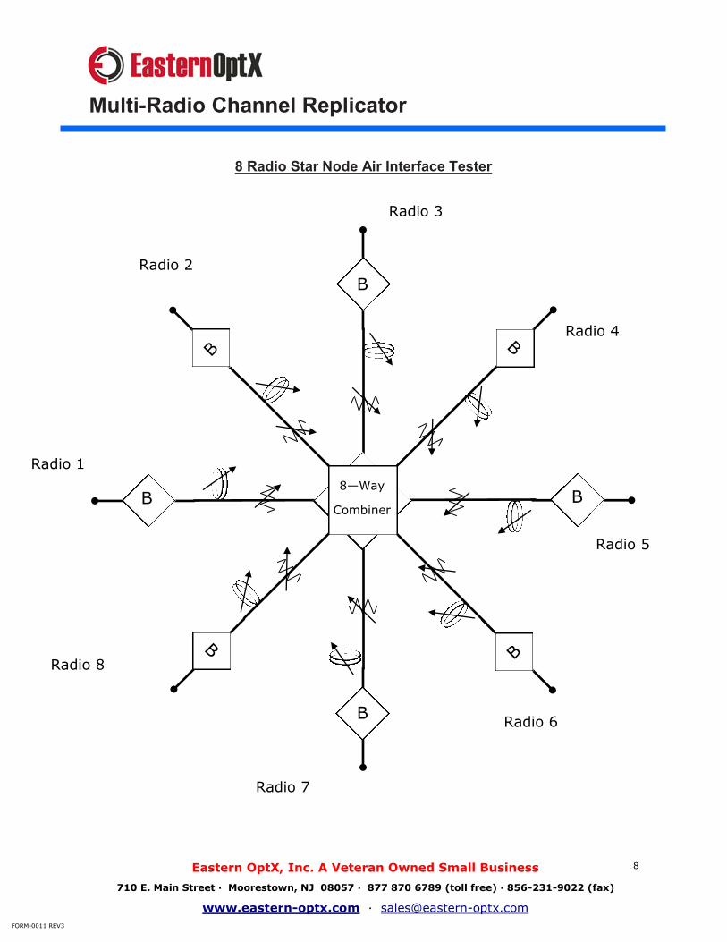
Multi-Radio Channel Replicator
8 Radio Star Node Air Interface Tester
B
B
B B
Radio 1
B B
B B
8—Way
Combiner
Radio 2
Radio 3
Radio 4
Radio 5
Radio 6
Radio 7
Radio 8
Eastern OptX, Inc. A Veteran Owned Small Business
710 E. Main Street ∙ Moorestown, NJ 08057 ∙ 877 870 6789 (toll free) ∙ 856-231-9022 (fax)
www.eastern-optx.com ∙ [email protected]
FORM-0011 REV3

9
Multi-Radio Channel Replicator
100 us
A
50 us
A
200 us
A
400 us
A
400 us
A
425 us 425 us
B B B
A
B B B B B
Figure 1. System Block Diagram
Radio
1
Radio
2
Radio
3
Radio
4
Radio
5
Radio
6
Radio
7
Radio
8
8 Radio Series Node Air Interface Tester
Eastern OptX, Inc. A Veteran Owned Small Business
710 E. Main Street ∙ Moorestown, NJ 08057 ∙ 877 870 6789 (toll free) ∙ 856-231-9022 (fax)
www.eastern-optx.com ∙ [email protected]
FORM-0011 REV3

10
Multi-Radio Channel Replicator
8 Radio Channel Replicator 150 NM Delays
Eastern OptX, Inc. A Veteran Owned Small Business
710 E. Main Street ∙ Moorestown, NJ 08057 ∙ 877 870 6789 (toll free) ∙ 856-231-9022 (fax)
www.eastern-optx.com ∙ [email protected]
FORM-0011 REV3

11
Multi-Radio Channel Replicator
8 Radio Channel Replicator
150 NM Delays
Eastern OptX, Inc. A Veteran Owned Small Business
710 E. Main Street ∙ Moorestown, NJ 08057 ∙ 877 870 6789 (toll free) ∙ 856-231-9022 (fax)
www.eastern-optx.com ∙ [email protected]
FORM-0011 REV3
GUI Features:
Individual Radio grouping and isolation capability
Moving Target Scenario Generator
Scenario Stacking
Individual Radio Distance Control
Propagation Loss Repli-cation
Gain Control
Band Selection