multi-protocol label switching (mpls)...
TRANSCRIPT

Multi-Protocol Label Switching (MPLS) Manager
User GuideDocument 5120

NoticeCopyright Notice Copyright © 2002-present by Aprisma Management Technologies, Inc. All rights reserved worldwide. Use, duplication, or disclosure by the United States government is subject to the restrictions set forth in DFARS 252.227-7013(c)(1)(ii) and FAR 52.227-19.
Liability Disclaimer Aprisma Management Technologies, Inc. (“Aprisma”) reserves the right to make changes in specifications and other information contained in this document without prior notice. In all cases, the reader should contact Aprisma to inquire if any changes have been made.
The hardware, firmware, or software described in this manual is subject to change without notice.
IN NO EVENT SHALL APRISMA, ITS EMPLOYEES, OFFICERS, DIRECTORS, AGENTS, OR AFFILIATES BE LIABLE FOR ANY INCIDENTAL, INDIRECT, SPECIAL, OR CONSEQUENTIAL DAMAGES WHATSOEVER (INCLUDING BUT NOT LIMITED TO LOST PROFITS) ARISING OUT OF OR RELATED TO THIS MANUAL OR THE INFORMATION CONTAINED IN IT, EVEN IF APRISMA HAS BEEN ADVISED OF, HAS KNOWN, OR SHOULD HAVE KNOWN, THE POSSIBILITY OF SUCH DAMAGES.
Trademark, Service Mark, and Logo Information SPECTRUM, IMT, and the SPECTRUM IMT/VNM logo are registered trademarks of Aprisma Management Technologies, Inc., or its affiliates. APRISMA, APRISMA MANAGEMENT TECHNOLOGIES, the APRISMA MANAGEMENT TECHNOLOGIES logo, MANAGE WHAT MATTERS, DCM, VNM, SpectroGRAPH, SpectroSERVER, Inductive Modeling Technology, Device Communications Manager, SPECTRUM Security Manager, and Virtual Network Machine are unregistered trademarks of Aprisma Management Technologies, Inc., or its affiliates. For a complete list of Aprisma trademarks, service marks, and trade names, go to:
http://www.aprisma.com/support/secure/manuals/trademark-list.htm
All referenced trademarks, service marks, and trade names identified in this document, whether registered or unregistered, are the intellectual property of their respective owners. No rights are granted by Aprisma Management Technologies, Inc., to use such marks, whether by implication, estoppel, or otherwise. If you have comments or concerns about trademark or copyright references, please send an e-mail to [email protected]; we will do our best to help.
Restricted Rights Notice (Applicable to licenses to the United States government only.)This software and/or user documentation is/are provided with RESTRICTED AND LIMITED RIGHTS. Use, duplication, or disclosure by the government is subject to restrictions as set forth in FAR 52.227-14 (June 1987) Alternate III(g)(3) (June 1987), FAR 52.227-19 (June 1987), or DFARS 52.227-7013(c)(1)(ii) (June 1988), and/or in similar or successor clauses in the FAR or DFARS, or in the DOD or NASA FAR Supplement, as applicable. Contractor/manufacturer is Aprisma Management Technologies, Inc. In the event the government seeks to obtain the software pursuant to standard commercial practice, this software agreement, instead of the noted regulatory clauses, shall control the terms of the government's license.
Virus Disclaimer Aprisma makes no representations or warranties to the effect that the licensed software is virus-free. Aprisma has tested its software with current virus-checking technologies. However, because no antivirus system is 100-percent effective, we strongly recommend that you write protect the licensed software and verify (with an antivirus system with which you have confidence) that the licensed software, prior to installation, is virus-free.
Contact Information Aprisma Management Technologies, Inc., 273 Corporate Drive, Portsmouth, NH 03801 USA
Phone: 603.334.2100U.S. toll-free: 877.468.1448Web site: http://www.aprisma.com

3
Contents
Preface . . . . . . . . . . . . . . . . . . . . . . . . . . . . . . . . . . . . . . . . . . . . . . . . . . . . . . . . . . . . . . 5
Chapter 1: Getting Started . . . . . . . . . . . . . . . . . . . . . . . . . . . . . . . . . . . . . . . . . . . . . . . 7
About SPECTRUM MPLS Manager . . . . . . . . . . . . . . . . . . . . . . . . . . . . . . . . . . . . . . . . . . 7
Installation . . . . . . . . . . . . . . . . . . . . . . . . . . . . . . . . . . . . . . . . . . . . . . . . . . . . . . . . . 7
MPLS Quick Start . . . . . . . . . . . . . . . . . . . . . . . . . . . . . . . . . . . . . . . . . . . . . . . . . . . . . 8
Chapter 2: Use Case Scenarios . . . . . . . . . . . . . . . . . . . . . . . . . . . . . . . . . . . . . . . . . . . . 9
Analyzing a device alarm impact on customer LSPs . . . . . . . . . . . . . . . . . . . . . . . . . . . . . 9
Network planning . . . . . . . . . . . . . . . . . . . . . . . . . . . . . . . . . . . . . . . . . . . . . . . . . . . . 11
New LSP for VPN service (LSP Creation Traps enabled) . . . . . . . . . . . . . . . . . . . . . . . . . 12
New LSP for VPN Service (LSP Creation Traps disabled) . . . . . . . . . . . . . . . . . . . . . . . . . 13
Chapter 3: Using MPLS . . . . . . . . . . . . . . . . . . . . . . . . . . . . . . . . . . . . . . . . . . . . . . . . . 15
Configuring MPLS . . . . . . . . . . . . . . . . . . . . . . . . . . . . . . . . . . . . . . . . . . . . . . . . . . . . 15
Performing MPLS discoveries . . . . . . . . . . . . . . . . . . . . . . . . . . . . . . . . . . . . . . . . . . . . 16
Performing a search . . . . . . . . . . . . . . . . . . . . . . . . . . . . . . . . . . . . . . . . . . . . . . . . . . 17
Filtering search results . . . . . . . . . . . . . . . . . . . . . . . . . . . . . . . . . . . . . . . . . . . . . . . . 18
Viewing LSP information . . . . . . . . . . . . . . . . . . . . . . . . . . . . . . . . . . . . . . . . . . . . . . . 18
Viewing Path Information . . . . . . . . . . . . . . . . . . . . . . . . . . . . . . . . . . . . . . . . . . . . . . 18
MPLS Manager Views . . . . . . . . . . . . . . . . . . . . . . . . . . . . . . . . . . . . . . . . . . . . . . . . . 19
Console view . . . . . . . . . . . . . . . . . . . . . . . . . . . . . . . . . . . . . . . . . . . . . . . . . . . . 19
Impact view . . . . . . . . . . . . . . . . . . . . . . . . . . . . . . . . . . . . . . . . . . . . . . . . . . . . . 20
Path view . . . . . . . . . . . . . . . . . . . . . . . . . . . . . . . . . . . . . . . . . . . . . . . . . . . . . . . 20
MPLS Console . . . . . . . . . . . . . . . . . . . . . . . . . . . . . . . . . . . . . . . . . . . . . . . . . . . . . . 20
MPLS Manager configuration . . . . . . . . . . . . . . . . . . . . . . . . . . . . . . . . . . . . . . . . . . . . 21
MPLS Manager Discovery options . . . . . . . . . . . . . . . . . . . . . . . . . . . . . . . . . . . . . . . . . 22
MPLS LSP searches . . . . . . . . . . . . . . . . . . . . . . . . . . . . . . . . . . . . . . . . . . . . . . . . . . 23
MPLS Path searches . . . . . . . . . . . . . . . . . . . . . . . . . . . . . . . . . . . . . . . . . . . . . . . . . . 25
MPLS Manager Fault Impact view . . . . . . . . . . . . . . . . . . . . . . . . . . . . . . . . . . . . . . . . . 28
LSP Information view . . . . . . . . . . . . . . . . . . . . . . . . . . . . . . . . . . . . . . . . . . . . . . . . . 29
Related paths . . . . . . . . . . . . . . . . . . . . . . . . . . . . . . . . . . . . . . . . . . . . . . . . . . . . 30
Unmodeled hops in MPLS . . . . . . . . . . . . . . . . . . . . . . . . . . . . . . . . . . . . . . . . . . . . 30
Path Information and Topology view . . . . . . . . . . . . . . . . . . . . . . . . . . . . . . . . . . . . . . 31
MPLS Impact Comparison View . . . . . . . . . . . . . . . . . . . . . . . . . . . . . . . . . . . . . . . . . . 32
Glossary of Terms . . . . . . . . . . . . . . . . . . . . . . . . . . . . . . . . . . . . . . . . . . . . . . . . . . . . 33
Current Device Support Matrix . . . . . . . . . . . . . . . . . . . . . . . . . . . . . . . . . . . . . . . . . . 35

4 Multi-Protocol Label Switching (MPLS) Manager User Guide
Contents
Issues Not Addressed . . . . . . . . . . . . . . . . . . . . . . . . . . . . . . . . . . . . . . . . . . . . . . . . . 37
Known Anomalies . . . . . . . . . . . . . . . . . . . . . . . . . . . . . . . . . . . . . . . . . . . . . . . . . . . . . 39
Index . . . . . . . . . . . . . . . . . . . . . . . . . . . . . . . . . . . . . . . . . . . . . . . . . . . . . . . . . . . . . . . 43

5
Preface
This guide is intended for Help Desk and NOC operators, network administrators, and MPLS administrators.
What is in this book
This guide contains the following chapters:
• Chapter 1: Getting Started - This chapter provides information on instalation and setup.
• Chapter 2: Use Case Scenarios - This chapter outlines scenarios that will lead you through typical usages of the MPLS Manager and provide practical applications of the product.
• Chapter 3: Using MPLS - The procedures in this chapter contain the step-by-step instructions for using the various functions and features of MPLS Manager.
• Glossary of Terms - Lists common names and abreviations associated with Multi-Protocol Label Switching.
• Current Device Support Matrix - Lists the devices that have been tested and are supported by MPLS Manager.
• Issues Not Addressed - Lists the items that will not be addressed with this release of MPLS Manager.
• Known Anomalies - Lists the known anomalies associated with this release of MPLS Manager.
Text Conventions
The following text conventions are used in this document:
Element Convention Used Example
Variables
(The user supplies a value for the variable.)
Courier and Italic in angle brackets (<>)
Type the following:
DISPLAY=<workstation name>:0.0 export display

6 Multi-Protocol Label Switching (MPLS) Manager User Guide
Preface
Document Feedback
Please send feedback regarding SPECTRUM documents to the following e-mail address:
Thank you for helping us improve our documentation.
Online Documents
SPECTRUM documents are available online at:
http://www.aprisma.com/manuals
Check this site for the latest updates and additions.
The directory where you installed SPECTRUM
(The user supplies a value for the variable.)
<$SPECROOT> Navigate to:
<$SPECROOT>/app-defaults
Solaris and Windows directory paths
Unless otherwise noted, directory paths are common to both operating systems, with the exception that slashes (/) should be used in Solaris paths, and backslashes (\) should be used in Windows paths.
<$SPECROOT>/app-defaults on Solaris is equivalent to <$SPECROOT>\app-defaults on Windows.
On-screen text Courier The following line displays:
path=”/audit”
User-typed text Courier Type the following path name:
C:\ABC\lib\db
Cross-references Underlined and hypertext-blue
See “Document Feedback” on page 6.
References to SPECTRUM documents (title and number)
Italic SPECTRUM Installation Guide (0675)
Element Convention Used Example

7
Chapter 1: Getting Started
In this chapter
• “About SPECTRUM MPLS Manager” on page 7
• “Installation” on page 7
• “MPLS Quick Start” on page 8
About SPECTRUM MPLS ManagerThe SPECTRUM Multiprotocol Label Switching (MPLS) Manager provides the foundation to allow service providers to manage the physical layer 2 connection services and the logical layer MPLS connections within a single platform. MPLS Manager is accessed through the SPECTRUM Web Operator interface. MPLS Manager provides complete visibility into all provisioned label switched paths (LSPs) and Paths on the current landscape, and knows the relationship between an LSP and its primary and secondary paths. MPLS Manager has the intelligence to provide the impact of an outage in terms of its affect on the MPLS infrastructure. MPLS Manager supports the MPLS implementations of multiple vendors as well as both proprietary and standards-based technologies.
InstallationAn MPLS installation is comprised of both SpectroSERVER and Web Operator Suite components. To successfully install MPLS you must:
1. Install SPECTRUM using an extraction key that includes MPLS (SA-MPLS-MGR). See the SPECTRUM Installation Guide (0675) for complete instructions.
1. Install the SPECTRUM Web Operator Suite using an extraction key that includes MPLS (SA-MPLS-MGR). See the SPECTRUM Web Operator Install Guide (5110) for complete instructions.
Note: To run MPLS, you will need to have modeled in Spectrum devices that support the Cisco MPLS TE MIB and the Juniper MPLS LSP MIB. See “Performing MPLS discoveries” on page 16 for more information.

8 Multi-Protocol Label Switching (MPLS) Manager User Guide
Chapter 1: Getting Started
MPLS Quick StartFor users familiar with MPLS concepts and SPECTRUM functionality, the Quick Start procedure will get the MPLS Manager product operational.
Procedure
1. Install the MPLS Manager product. (SPECTRUM Web Operator must be previously installed.)
2. Log in to SPECTRUM Web Operator as a user with administrator rights.
3. Click MPLS Manager on the SPECTRUM Web Operator application menu bar.
4. Click MPLS Manager Configurations and set the Impact Threshold Values. See “MPLS Manager configuration” on page 21 for more information.
5. Model the LSP devices on the network. See “Device Reconfiguration Discovery” on page 22 for more information.
• If the network has existing SPECTRUM models:
- Click MPLS Discovery Options.
- Click Start on the Device Reconfiguration Discovery panel.
• If this is a new SPECTRUM installation:
- Perform a SPECTRUM AutoDiscovery or manually model the network. See the AutoDiscovery User Guide (0727) or How to Manage Your Network with SPECTRUM (1909) for more information.
6. Discover the LSPs on the network. See “LSP Discovery” on page 23 for more information.
• Click Start on the LSP Discovery panel.
7. Search for the LSPs on the network. See “MPLS LSP searches” on page 23 for more information.
• Click MPLS Manager on the SPECTRUM Web Operator application menu bar.
• Click All LSPs in the LSP Search list on the MPLS Manager Console.
• View the Search results. See “LSP Search Results” on page 24 for more information.

9
Chapter 2: Use Case Scenarios
The following scenarios will lead you through typical usages of the MPLS Manager and provide practical applications of the product.
Scenarios:
• “Analyzing a device alarm impact on customer LSPs” on page 9
• “Network planning” on page 11
• “New LSP for VPN service (LSP Creation Traps enabled)” on page 12
• “New LSP for VPN Service (LSP Creation Traps disabled)” on page 13
Analyzing a device alarm impact on customer LSPsDescription:
A trouble ticket is generated against a core router; a card within the chassis has failed.
• The trouble is routed based on the device class to the level 2 operations group. This group focuses solely on maintaining the core routing infrastructure.
• The company’s network management application has identified the router in question and the offending board.
• The level 2 support group currently has a backlog of 25 open tickets for a variety of issues.
• The operators are currently using their knowledge of the core network to make decisions regarding issue prioritization.
Results without MPLS:
• The level 2 operators do not understand the impact a failed network device has on the MPLS topology.
• The operator has no means to correlate a device failure with the impact it is having on the Service Provider’s business.
• For a particular outage, the operator cannot understand which LSPs are no longer available, or which end-to-end paths have been affected.

10 Multi-Protocol Label Switching (MPLS) Manager User Guide
Chapter 2: Use Case Scenarios
• The operator cannot tell if an outage has had a minor impact (such as the loss of a yet-unused secondary LSP) or, a critical impact (such as the complete loss of an end-to-end path).
• The operator does not know how to prioritize the resolution of detected network faults. This failure to properly prioritize the correction of network faults may result in resolution of non-critical faults occurring before critical faults.
Time to complete with MPLS Manager:
The expected time for the helpdesk to find the problem in the trouble ticket and relay the information to the customer is less than 5 minutes depending on the number of open trouble tickets.
This provides a time savings to the customer by reducing by 25 minutes the amount of time it takes to determine the problem. Application administrators realize a time savings of 15-45 minutes by eliminating the duplicated efforts on troubleshooting multiple symptoms of the same problem.
Assumptions:
1. The MPLS Manager has been installed and configured. See “MPLS Manager configuration” on page 21 for more information.
2. The discovery of the network had been completed and impact severity thresholds have been assigned to LSPs. See “MPLS Manager Discovery options” on page 22 for more information.
3. All services have been modeled in SPECTRUM.
4. There is no secondary path for this site.
Scenario with SPECTRUM and MPLS Manager:
1. A router in the network goes down and is detected by SPECTRUM.
2. SPECTRUM generates an alarm indicating that the router is down.
3. The operator receives the alarm in Web Alarm View. The operator verifies the alarm by pinging the router and receiving no response.
4. The network operator checks the MPLS impact of the alarm by clicking on the Impact value for the alarm in Web Alarm View. See “MPLS Manager Fault Impact view” on page 28.
5. SPECTRUM Web Alarm View displays the Fault Impact view. All LSPs affected by the router outage are displayed in the list. See Figure 3-8 on page 28.
6. The network operator creates a trouble ticket including the impacted LSPs, and assigns it to the network administrator. The network operator consults the Path view and confirms that the affected LSP passes through the down router. See Figure 3-12 on page 31.
7. The network administrator receives the trouble ticket and begins troubleshooting the problem.

Network planning
Multi-Protocol Label Switching (MPLS) Manager User Guide 11
Network planningDescription:
Network instability has been reported by the level 2 operation group and a trouble ticket has been generated. While trouble shooting a slow access issue, the level 2 operator observed a number of LSP path changes over a short period of time.
• Level 3 network analyst responds to trouble tickets issued against network stability and design issues.
• The level 3 group consists of 10 analysts with a variety of responsibilities including network planning and configuration.
• This group typically does not have a backlog of tickets.
• They rely on their network knowledge and documentation of network design to troubleshoot instability issues.
Results without MPLS Manager:
• Network instability problems persist in the environment due to a lack of visibility into the MPLS infrastructure. The operation group only notices these issues when troubleshooting element failure or access-related issues.
• Once an issue is escalated to the network analyst they are then forced to look at log files from a provisioning system or spreadsheets they created to see how the network was originally configured. It takes too long to resolve a failure that occurs within an MPLS network because the network analyst does not have sufficient visibility into their MPLS network.
• The network analyst is unable to view information regarding both the components and the route of an individual LSP. As such, the analyst has a difficult time restoring the network to its properly configured state (i.e. the topology that was designed by the network planner).
• These network instabilities are currently very difficult to track and report on so they are typically not reported to the network analysts. The result is a relatively low occurrence of these tickets within the environment.
• These instability issues can be very difficult to resolve based on potential re-route issues or network reconfigurations.
Time to complete with MPLS Manager:
The expected time for the helpdesk to find the problem in the trouble ticket and relay the information to the customer is less than 5 minutes depending on the number of open trouble tickets.
MPLS Manager saves the customer at least 25 minutes in this scenario by locating the problem and 15 to 45 minutes for each of the application administrators by eliminating duplicated efforts spent troubleshooting multiple symptoms of the same problem.
Assumptions:
1. The MPLS Manager has been installed and configured. See “MPLS Manager configuration” on page 21 for more information.

12 Multi-Protocol Label Switching (MPLS) Manager User Guide
Chapter 2: Use Case Scenarios
2. The discovery of the network had been completed and impact severity thresholds have been assigned to LSPs. See “MPLS Manager Discovery options” on page 22 for more information.
3. All services have been modeled in SPECTRUM.
4. The appropriate steps have been taken to ensure that an alarm is generated on violation of a threshold for path changes.
Scenario with SPECTRUM and MPLS Manager:
A SpectroWATCH triggers an alarm for network instability based on an excessive number of path changes. The alarms are forwarded to the trouble ticketing system and a ticket is assigned to the level 3 network analyst for resolution.
The network analyst can react to potential network instabilities proactively based on path thresholds being violated. This allows the analyst to isolate and resolve the instability prior to it causing a service outage.
1. SpectroWATCH generates an alarm based on a threshold violation for path changes.
2. A trouble ticket is created for network instability (Excess Path changes within defined interval).
3. The trouble ticket is assigned to an analyst.
4. The analyst views the alarm in Web Alarm View.
5. The analyst evaluates the network’s current design by completing a path trace (see “Path Information and Topology view” on page 31).
6. The analyst compares results of path trace with the intended network design.
7. The analyst consults traffic engineering tools to look for potential causes for network instability (for example, the traffic requirements of one LSP consuming all of the available bandwidth).
8. The analyst creates a new device configuration.
9. New configuration is loaded onto the network element.
10. The analyst executes a path search to verify the new path.
New LSP for VPN service (LSP Creation Traps enabled)Description:
A new customer has signed on for VPN service and a new LSP has been provisioned through the network to link the customer’s 2 main locations. The level 2 support operator has been asked to verify that SPECTRUM is monitoring this new LSP.
Time to complete with MPLS Manager:
One minute.
Assumptions:
1. The MPLS Manager has been installed and configured. See “MPLS Manager configuration” on page 21 for more information.
2. Customer has modeled the physical devices within SPECTRUM.

New LSP for VPN Service (LSP Creation Traps disabled)
Multi-Protocol Label Switching (MPLS) Manager User Guide 13
3. Devices have been configured to send traps to SPECTRUM for new LSP creation.
4. Customer maintains a strict LSP naming convention (Account #).
Scenario with SPECTRUM and MPLS Manager:
1. The operator launches SPECTRUM Web Operator Suite.
2. The operator selects Model Search tab from WOS toolbar.
3. List of predefined searches returns.
4. The operator selects search for LSP by name.
5. The operator prompted for additional information (LSP name).
6. The operator enters the customers account number into the LSP name field and selects partial text search then hits enter.
7. A list returns with the results of the search (all LSPs matching the criteria).
8. The operator verifies that SPECTRUM has modeled an LSP matching the customers account number.
New LSP for VPN Service (LSP Creation Traps disabled)Description:
A new customer has signed on for VPN service and a new LSP has been provisioned through the network to link the customer’s 2 main locations. The Level 2 support operator has been asked to verify that SPECTRUM is monitoring this new LSP.
Time to complete with MPLS Manager:
Five minutes.
Assumptions:
1. The MPLS Manager has been installed and configured. See “MPLS Manager configuration” on page 21 for more information.
2. Customer has modeled the physical devices within SPECTRUM.
3. Devices have not been configured to send traps to SPECTRUM for new LSP creation.
4. The operator has sufficient security privileges to launch the WOS admin tool.
5. Customer maintains a strict LSP naming convention (Account #).
Scenario with SPECTRUM and MPLS Manager:
1. The operator launches SPECTRUM Web Operator Suite.
2. The operator selects WOS Admin view.
3. The operator selects MPLS manager.
4. The operator pushes MPLS reconfiguration button.

14 Multi-Protocol Label Switching (MPLS) Manager User Guide
Chapter 2: Use Case Scenarios
5. All MPLS enabled device models in SPECTRUM contact the device and read the LSR and TE MIBs for new LSPs and Paths. Any newly discovered LSPs are modeled within SPECTRUM.
6. The operator selects Model Search tab from WOS toolbar.
7. List of predefined searches returns.
8. The operator selects search for LSP by name.
9. The operator prompted for additional information (LSP name).
10. The operator enters the customer’s account number into the LSP name field and selects partial text search then hits enter.
11.A list returns with the results of the search (all LSPs matching the criteria).
12. The operator verifies that SPECTRUM has modeled an LSP matching the customer’s account number.

15
Chapter 3: Using MPLS
The procedures in this chapter contain the step-by-step instructions for using the various functions and features of MPLS Manager.
In this chapter
• “Configuring MPLS” on page 15
• “Performing MPLS discoveries” on page 16
• “Performing a search” on page 17
• “Filtering search results” on page 18
• “Viewing LSP information” on page 18
• “Viewing Path Information” on page 18
• “MPLS Manager Views” on page 19
• “MPLS Console” on page 20
• “MPLS Manager configuration” on page 21
• “MPLS Manager Discovery options” on page 22
• “MPLS LSP searches” on page 23
• “MPLS Path searches” on page 25
• “MPLS Manager Fault Impact view” on page 28
• “LSP Information view” on page 29
• “Path Information and Topology view” on page 31
• “MPLS Impact Comparison View” on page 32
Configuring MPLSThe Impact Threshold Values and Impact Weight Values are used when determining the Impact value of an alarm. These values have default settings which may be reconfigured as necessary.

16 Multi-Protocol Label Switching (MPLS) Manager User Guide
Chapter 3: Using MPLS
Procedure
1. Log in to SPECTRUM Web Operator as an Administrator user.
2. Click MPLS Manager on the application menu bar.
3. Click the MPLS Manager Configuration button.
4. If you are working in a distributed environment, select the appropriate SpectroSERVER.
5. Click in the desired field(s) and enter the desired value(s). See “MPLS Manager configuration” on page 21 for information on how these values are used.
6. Click in the checkbox(es) to select the desired SNMP Trap options. See “SNMP Trap Configuration for MPLS” on page 22 for more information.
7. Click Save.
Performing MPLS discoveriesDevices which support MPLS must be modeled in the SPECTRUM database. MPLS Manager provides the Device Reconfiguration Discovery migration tool to find all existing device models that support MPLS and remodel them with the MIB information required for MPLS. See “Device Reconfiguration Discovery” on page 22 for more information.
For a new SPECTRUM installation, the network must be modeled with AutoDiscovery or manually modeled prior to performing the LSP Discovery. This network model must include devices that support the Cisco MPLS TE MIB or the Juniper MPLS LSP MIB. See the AutoDiscovery User Guide (0727) or How to Manage Your Network with SPECTRUM (1909) for more information.
Procedure
1. Model the LSP devices on the network.
• If the network has existing SPECTRUM models:
- Click MPLS Manager on the Web Operator application menu bar.
- Click MPLS Discovery Options.
- If you are working in a distributed environment, select the appropriate SpectroSERVER.
- Click Start on the Device Reconfiguration Discovery panel.
The status field will change from Idle to Running. Once the Device Reconfiguration Discovery is complete, the status field will return to Idle.
OR
• If this is a new SPECTRUM installation:
- Perform a SPECTRUM AutoDiscovery or manually model the network.
2. Discover and model the LSPs on the network. See “LSP Discovery” on page 23 for more information.
• Click Start on the LSP Discovery panel.

Performing a search
Multi-Protocol Label Switching (MPLS) Manager User Guide 17
The status field will change from Idle to Running. Once the LSP Discovery has completed, the status field will return to Idle.
The time to required to complete the LSP Discovery will depend on the number of devices that support MPLS on the network and their contact status. If devices are unreachable the discovery may take significantly longer and incomplete MPLS information may be obtained. The discovery may also run so quickly that the status field may not appear to change.
Performing a searchThe LSP and Path searches are all accessed from the MPLS Console view. When performing searches other than All LSPs or All Paths, enter a string in the search field. The search is case sensitive and will match a partial string.
For example, the current database contains three LSPs named Tunnel1, Tunnel2, and Tunnel123. A search for Tunnel1 will find Tunnel1 and Tunnel123, but a search for tunnel1 will return “No models found” as none of the names begin with a lowercase letter.
The LSP by ID and Path by ID searches require an integer as the search string. These searches also match on partial strings.
Procedure
1. Click MPLS Manager on the Web Operator application menu bar.
2. Click the link of the desired search.
3. For searches other than All LSPs or All Paths, enter the desired search string in the Search Field(s).
Figure 3-1: Single Search Field
4. Click Search to start the search.
Click Reset Form to clear the search fields.
5. The search results will be displayed. These results can be further filtered. See “Filtering search results” on page 18 for more information.

18 Multi-Protocol Label Switching (MPLS) Manager User Guide
Chapter 3: Using MPLS
Filtering search resultsA smaller sub-set of the search results can be identified by filtering the results that are currently displayed.
Procedure
1. Perform the desired search. See “Performing a search” on page 17.
2. Select the desired filter from the drop down list.
The filters available are dependent on the type of search performed.
- For LSP searches the filters are Condition, Name, LSP ID, From Model Name, To Model Name, and # of Path Changes.
- For Path searches the filters are Condition, Name, Path ID, From Model Name, To Model Name, and Number of Hops.
3. Enter the desired string and click Go.
The filtered results will display.
4. Click Clear to return to the previous results.
Viewing LSP informationSee also:
• “MPLS LSP searches” on page 23
• “LSP Search Results” on page 24
• “LSP Information View” on page 29
Procedure
1. Click MPLS Manager on the Web Operator application menu bar.
2. Perform the desired LSP search.
3. Click on the name of the desired LSP in the Search Results view. The LSP Information view is displayed.
Viewing Path InformationSee also:
• “MPLS Path searches” on page 25
• “Path Search Results” on page 26
• “Path Information and Topology View” on page 31
Procedure
1. Click MPLS Manager on the Web Operator application menu bar.

MPLS Manager Views
Multi-Protocol Label Switching (MPLS) Manager User Guide 19
2. Perform the desired Path search.
3. Click on the name of the desired Path in the Search Results view. The Path Information view is displayed.
MPLS Manager ViewsFigure 3-2 provides a navigational map of the MPLS Manager views.
Figure 3-2: MPLS Manager Views
MPLS Manager provides the following main views: Console, Impact, and Path.
Console view
You can search for all the LSPs and Paths currently modeled in SPECTRUM or a filtered list of those LSPs and Paths. Custom searches for LSPs and Paths are available from this view as well. These searches can serve as starting points to answer questions such as: How many LSPs or Paths transverse this device? How many LSPs connect point A to point Z? What is the current path of LSP 1234? See “MPLS Console” on page 20.
Web Operator Suite
“MPLS Console”
“MPLS LSP searches”
“LSP Information view”
Includes graphical “Related paths” information and list. (Click a Name link from the list to open Path Information View for that LSP)
“LSP Search Results” (click LSP Name link in Search Results to open LSP Information View)
“MPLS Manager configuration” (Admin User only)
“MPLS Manager Discovery options” (Admin User only)
“MPLS Path searches”
“Path Information and Topology view”
“Path Search Results” (click a Path Name link in Search Results to open Path Information View for that Path)
Web Alarm Manager
“MPLS Impact Comparison View”
20 Multi-Protocol Label Switching (MPLS) Manager User Guide
Chapter 3: Using MPLS
Impact view
MPLS Manager provides prioritization of certain network alarms based on their impact to the service delivery infrastructure. Alarms for models of devices, physical and logical interfaces, Wide Area Links (WA_Link), and fanouts will have an impact which consists of the sum of the number of LSPs down, the number of LSPs switched, and the number of LSPs at risk. This impact can then be applied against a threshold value to provide an MPLS impact severity (Minor, Major, Critical). This allows an operator the ability to see not only the criticality of the device alarm from a strict physical perspective, but also the impact severity of the alarm in terms of its affect on the logical MPLS infrastructure. See “MPLS Manager Fault Impact view” on page 28.
Path view
This view provides the lowest level of MPLS visualization granularity. The filtered topology view shows the path a selected LSP Path traverses through the network. You are presented with a graphical representation of the LSP Path with icons for each device and physical interface traversed from the ingress to the egress point of the LSP. The device and interface icons are updated to their current state each time the view is refreshed. See “Path Information and Topology view” on page 31.
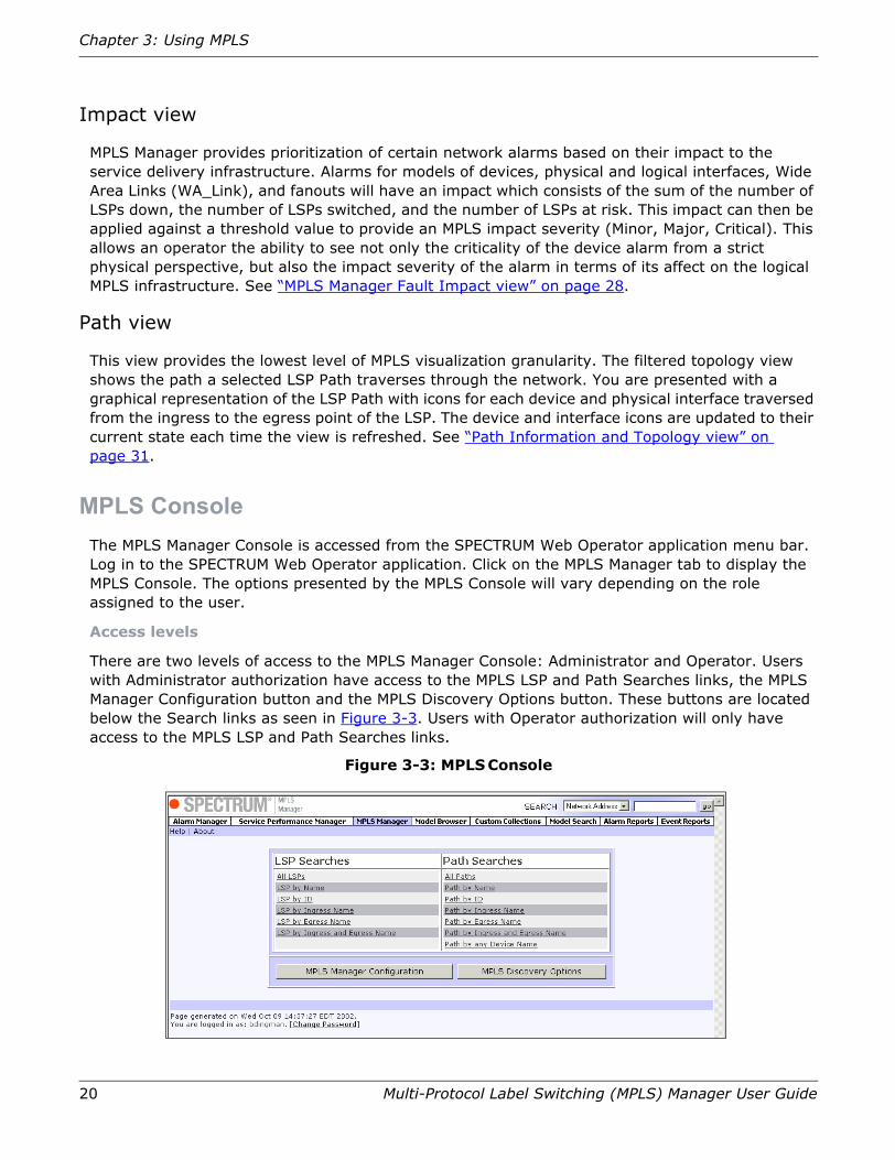
MPLS ConsoleThe MPLS Manager Console is accessed from the SPECTRUM Web Operator application menu bar. Log in to the SPECTRUM Web Operator application. Click on the MPLS Manager tab to display the MPLS Console. The options presented by the MPLS Console will vary depending on the role assigned to the user.
Access levels
There are two levels of access to the MPLS Manager Console: Administrator and Operator. Users with Administrator authorization have access to the MPLS LSP and Path Searches links, the MPLS Manager Configuration button and the MPLS Discovery Options button. These buttons are located below the Search links as seen in Figure 3-3. Users with Operator authorization will only have access to the MPLS LSP and Path Searches links.
Figure 3-3: MPLS Console

MPLS Manager configuration
Multi-Protocol Label Switching (MPLS) Manager User Guide 21
MPLS Manager configurationThis view (Figure 3-4 on page 21) provides configuration options for impact calculation as well as “SNMP Trap Configuration for MPLS” on page 22.
If you are working in a distributed environment, you will be asked to select the appropriate SpectroSERVER when accessing this view.
Impact Threshold and Weight Values
In the Web Alarm Manager Alarm List, each alarm has a value in the Impact column. This impact value provides more information about the severity of a given alarm. MPLS Manager supports impact calculation for models of devices, physical and logical interfaces, Wide Area Links (WA_Link), and fanouts.
Note: Because of the way tunnel interfaces are represented as distinct entities in certain MPLS MIBs such as the Cisco TE MIB (see “Current Device Support Matrix” on page 35), SPECTRUM does not poll, generate alarms on, or calculate impact for them.
The Impact Threshold Values and Impact Weight Values are used when determining the Impact value of an alarm. The default settings are listed in Table 3-1. The Impact value is calculated using the following formula:
Impact value = (# of Down LSPs x Down LSP weight) + (# of Switched LSPs x Switched LSP weight) + (# of At Risk LSPs x At Risk LSP weight)For example, there are 3 down LSPs, 4 switched LSPs and 3 At Risk LSPs. Using the default settings for the Weight values, the Impact value for the alarm would be (3 x 100) + (4 x 10) + (3 x 5) = 300 + 40 + 15 = 355. This would cause the Impact value to exceed the Major threshold.
Table 3-1: Impact Threshold and Weight Default Values
Figure 3-4: MPLS Configuration
Impact Threshold Values Default Impact Weight Values Default
Critical Threshold Value 700 Down LSP Weight 100
Major Threshold Value 350 Switched LSP Weight 10
Minor Threshold Value 1 At Risk LSP Weight 5

22 Multi-Protocol Label Switching (MPLS) Manager User Guide
Chapter 3: Using MPLS
SNMP Trap Configuration for MPLS
The MPLS Manager Configuration view provides options relating to traps and LSPs. When these options are checked, MPLS automatically maintains the LSP models for the network. If these are deselected, you must manually maintain the MPLS topology by first deleting all MPLS path and LSP models from the SPECTRUM database using Search Manager and then re-running LSP Discovery.
• Create LSP on Trap
When the TunnelUp trap is received and the model already exists, MPLS creates an LSP model.
• Delete LSP on Trap
When the TunnelDown trap is received, MPLS deletes the LSP and its associated Path models if the tunnel no longer exists in the device.
• Update LSP on Trap
When the TunnelRerouted trap is received, if an LSP model exists for the LSP, all Paths for that LSP model are deleted and MPLS remodels the LSP.
• Enable Port Polling
Enabled by default, this option must be checked for impact to be calculated for ports which are part of an LSP.
MPLS Manager Discovery optionsThe MPLS Manager LSP Discovery will automatically find all LSPs and model the LSPs and Paths in SPECTRUM. If devices with MPLS support were modeled prior to the installation of MPLS Manager, the “Device Reconfiguration Discovery” on page 22 migration tool should be used.
If you are working in a distributed environment, you will be asked to select the appropriate SpectroSERVER when accessing this view.
Figure 3-5: MPLS Discovery Options
Device Reconfiguration Discovery
Device Reconfiguration Discovery is a migration tool that should be used to find all existing device models in the current landscape that support MPLS and remodel them with the correct MIB information for MPLS.

MPLS LSP searches
Multi-Protocol Label Switching (MPLS) Manager User Guide 23
LSP Discovery
LSP Discovery will automatically discover all LSPs that are set up on the devices in the SPECTRUM database, then model the LSPs and Paths in SPECTRUM.
MPLS LSP searchesThe LSP is the path along which labeled packets are forwarded. From the MPLS Manager Console, you can search for LSPs that exist in the network by clicking on the desired link. The search results are displayed as seen in Figure 3-6 on page 24. The following searches are available:
All LSPs
This search locates all LSPs that have been modeled in the SPECTRUM database for the network.
LSP by Name
This search locates all LSPs whose name contains the string entered in the search field. See “Performing a search” on page 17 for details on entering the search string and the expected results.
LSP by ID
This search locates all LSPs whose ID number matches the number entered in the search field. See “Performing a search” on page 17 for details on entering the search string and the expected results.
LSP by Ingress Name
This search locates all LSPs whose Ingress model name contains the string entered in the search field. This name may also be the IP address of the model. See “Performing a search” on page 17 for details on entering the search string and the expected results.
LSP by Egress Name
This search locates all LSPs whose Egress model name contains the string entered in the search field. This name may also be the IP address of the model. See “Performing a search” on page 17 for details on entering the search string and the expected results.
LSP by Ingress and Egress Name
This search locates all LSPs whose Ingress or Egress model names contain the string entered in the search field. The names may also be the IP address of the model. See “Performing a search” on page 17 for details on entering the search string and the expected results.

24 Multi-Protocol Label Switching (MPLS) Manager User Guide
Chapter 3: Using MPLS
Figure 3-6: LSP Search Results
LSP Search Results
The search results for any of the LSP searches will display the information listed in Table 3-2 for each LSP. Additionally, you can filter the results by any one of the columns and configure the layout of the results. See “Filtering search results” on page 18 for more information.
Table 3-2: LSP Search Results Information
Column Heading Definition
Condition The condition of the LSP. See “LSP Conditions” for more information.
Name The name of the LSP. This may be an actual name given to the LSP or the IP address of the LSP.
LSP ID The ID assigned to the LSP.
From Model Name The Name (or IP Address) of the Ingress model.
To Model Name The Name (or IP Address) of the Egress model.
# of Path Changes The number of times the LSP has switched from its Primary to Secondary path.

MPLS Path searches
Multi-Protocol Label Switching (MPLS) Manager User Guide 25
LSP Conditions
There are several different conditions that describe the current state of the LSP. These are defined in Table 3-3.
Table 3-3: LSP Conditions
MPLS Path searchesA Path is the data path defined hop by hop. From the MPLS Manager Console, you can search for Paths by clicking on the desired link. The search results are displayed as seen in Figure 3-7 on page 26. The following searches are available:
All Paths
This search locates all Paths that have been modeled in the SPECTRUM database for the network.
Paths by Name
This search locates all Paths whose name contains the string entered in the search field. See “Performing a search” on page 17 for details on entering the search string and the expected results.
Paths by ID
This search locates all Paths whose ID number matches the number entered in the search field. See “Performing a search” on page 17 for details on entering the search string and the expected results.
Paths by Ingress Name
This search locates all Paths whose Ingress model name contains the string entered in the search field. The name may also be the IP address of the model. See “Performing a search” on page 17 for details on entering the search string and the expected results.
Paths by Egress Name
This search locates all Paths whose Egress model name contains the string entered in the search field. The name may also be the IP address of the model. See “Performing a search” on page 17 for details on entering the search string and the expected results.
Condition Name Definitions
Initial Modeled, but no Paths exist.
Down All paths are down including Primary and Secondary.
Switched The LSP has switched from the Primary path to a Secondary path.
At Risk The LSP has a major alarm but is still up. Secondary path is down.
Good All paths are up; using the Primary path.

26 Multi-Protocol Label Switching (MPLS) Manager User Guide
Chapter 3: Using MPLS
Paths by Ingress and Egress Names
This search locates all Paths whose Ingress and Egress model names contain the string entered in the search field. The names may also be the IP address of the model. See “Performing a search” on page 17 for details on entering the search string and the expected results.
Path by Any Device Name
This search locates all Paths that contains the device entered in the search field. The name may also be the IP address of the model. See “Performing a search” on page 17 for details on entering the search string and the expected results.
Figure 3-7: Paths Search Results
Path Search Results
The search results for any of the Path searches (Figure 3-7 on page 26) will display the information listed in Table 3-4 on page 27 for each Path. Additionally, you will be able to filter the results by any one of the columns and configure the layout of the results. See “Filtering search results” on page 18 for more information. Clicking on a path name will display the “Path Information and Topology view” on page 31.
Add to Collection
See the SPECTRUM Web Operator User Guide (5078) for information about working with Custom Collections.
Export Path Data
MPLS Manager table views (such as “Path Search Results” on page 26) that display paths also let you export path data to a text file. To do this, select the checkboxes of the path(s) you want to export data from and click Export Path Data. The selected path(s) will be exported into a comma-separated model name list. Each line will consist of the path model name followed by each model in the path, including egress and ingress ports for each hop. Unmodeled hops will be filled in with the ingress IP address for the ingress hop and 0s for the device and egress (because only the ingress IP of an unmodeled hop is known to MPLS Manager). You will be prompted to save the generated text file.

MPLS Path searches
Multi-Protocol Label Switching (MPLS) Manager User Guide 27
Table 3-4: Path Search Results Information
Path Conditions
There are two different conditions that describe the current state of the Path. These are defined in Table 3-5.
Table 3-5: Path Conditions
Column Heading Definition
Condition The condition of the Path. See “Path Conditions” on page 27 for more information.
Name The name of the Path. This may be an actual name given to the Path or the IP address of the Path.
Path ID The ID assigned to the Path.
From Model Name The Name (or IP Address) of the Ingress model.
To Model Name The Name (or IP Address) of the Egress model.
Number of Hops The number of devices in the path not including the Ingress device.
Condition Name Definitions
Normal All devices in the path are functional.
Critical Data is not able to pass from the Ingress to the Egress point.

28 Multi-Protocol Label Switching (MPLS) Manager User Guide
Chapter 3: Using MPLS
MPLS Manager Fault Impact viewWhen an alarm in Web Alarm Manager shows an Impact value, you can click on that value to view the LSP Fault Impact information for that alarm. The Fault Impact view displays the information listed in Table 3-6 on page 28 for each LSP. The “LSP Information view” on page 29 is accessed by clicking on the name of the desired LSP. The “MPLS Impact Comparison View” on page 32 is accessed by clicking on the weight value of the desired LSP.
Figure 3-8: Impact View
Table 3-6: Fault Impact View LSP Information
Column Heading Definition
Condition The condition of the LSP. See “LSP Conditions” on page 25 for more information.
Name The name of the LSP. This may be an actual name given to the LSP or the IP address of the LSP.
LSP ID The ID assigned to the LSP.
Current Path in Use The name of the Path currently being used to transfer data.
Weight The Impact Weight value for the LSP. This value is used to calculate the Impact value for MPLS Impact. See “MPLS Manager configuration” on page 21 for more information.

LSP Information view
Multi-Protocol Label Switching (MPLS) Manager User Guide 29
LSP Information viewThe LSP Information view (Figure 3-9 and Figure 3-10 on page 30) displays the Name, Condition, and LSP ID for the LSP. Additionally, the view contains the information listed in Table 3-7. The display also contains related path information.
Figure 3-9: LSP Information View
Table 3-7: LSP Information
Item Description
LSP Creation Time The date/time the LSP was created.
# of Path Changes The number of times the path has switched between the Primary and Secondary paths.
Last Path Change The date/time the path last changed.
Current Path in Use The name of the path currently in use.
From Model Name/IP Address Ingress device name/IP
To Model Name/IP Address Egress device name/IP
Related Paths page 30 Any additional paths that are related to the LSP.

30 Multi-Protocol Label Switching (MPLS) Manager User Guide
Chapter 3: Using MPLS
Related paths
This section of the “LSP Information View” on page 29 displays any additional paths that are related to the LSP. The first two related paths are shown graphically and all related paths are listed in a table below any graphical paths. Clicking on a path name in the table will display the “Path Information and Topology View” on page 31 for that path.
Clicking on a device model in a graphical path selects it and, if that device exists in another visible graphical path, centers the other path’s display on its instance of that same device model. Double-clicking a model in a graphical path opens the Model Browser view for that model.
Figure 3-10: LSP Information View - Related Paths
Unmodeled hops in MPLS
LSP paths can contain nodes that appear as unmodeled hops. The IPs of any unmodeled hops in a graphical path are provided in the unmodeled node’s icon (Figure 3-11 on page 31). Unmodeled hops may exist if the device is actually not modeled or because:
• The device is modeled on a different landscape
• The device is modeled but with an incorrect community name
If you have paths with unmodeled hop icons (Figure 3-11 on page 31):
1. We recommend that you model all MPLS path nodes on a single server. Ensure that the node is modeled in the correct landscape, with the correct community name.
2. If it is unmodeled, model it by IP from within the SpectroGRAPH.
3. Once modeled, update the MPLS path data by using Search Manager or Web Operator Model Search to find and destroy all models of type "MplsPath" which contain the unmodeled hop.

Path Information and Topology view
Multi-Protocol Label Switching (MPLS) Manager User Guide 31
4. Once the existing path models have been removed, run MPLS Manager discovery (see “MPLS Manager Discovery options” on page 22) This should restore the paths with the missing hop now modeled.
Figure 3-11: Unmodeled Node
Path Information and Topology viewThe Path Information and Topology view (Figure 3-12) displays the Name, Condition, and Path ID for the Path. Additionally, the view contains the information listed in Table 3-8 on page 32. The display contains a Topology view with icons for each device model in the path. See “Path view” on page 20 for more information.
Figure 3-12: Path Information and Topology View

32 Multi-Protocol Label Switching (MPLS) Manager User Guide
Chapter 3: Using MPLS
Table 3-8: Path Information
MPLS Impact Comparison ViewWhen an alarm in Web Alarm Manager shows an Impact value, you can click on that value to view the LSP Fault Impact information for that alarm. If more than one alarm has an Impact value, clicking on the Weight column for the LSP displays the MPLS Impact Comparison View. The MPLS Impact column will list the value for each LSP shown. The value cell is color coded to provide you with a quick visual overview of the device that has the most impact on MPLS.
Figure 3-13: Impact Comparison View
Item Description
From Model/IP Name Ingress device/IP name
To Model/IP Name Egress device/IP name
Number of Hops The number of devices in the path not including the Ingress device.
Number of Associated LSPs The number of LSPs associated with this path.

33
Glossary of Terms
Term Definition
Explicit Route A route specified as a non-empty list of hops that must be part of the route used. If an explicit route is strict, only specified hops may be used. If an explicit route is loose, all specified hops must be included, in order, in the resulting path, but the path is otherwise unrestricted.
FEC Forward Equivalency Class — A description of the criteria used to determine that a set of packets is to be forwarded in an equivalent fashion (along the same logical LSP). Forwarding equivalence classes are defined in the base LDP specification and may be extended through the use of additional parameters (such as is the case with CR-LDP). FECs are also represented in other label distribution protocols.
Label A fixed-size field contained in a message header that may be used as an exact-match key in determining how to forward a protocol data unit.
LDP Label Distribution Protocol — Process by which labels are negotiated between peer LSRs.
LER Label Edge Router — A term often used to indicate an LSR that is able to provide ingress to and egress from an LSP. In individual implementations, this tends to be a function of the capabilities of device interfaces more than of the overall device. In theory, it is possible for a device to be an LER and not an LSR (if it is not able to swap labels, for instance); however, it is unlikely that such an LER would be generally useful or make any particular sense in a cost-benefit analysis.
LSP Label Switch Path — Path along which labeled packets are forwarded. Packets forwarded using any label are forwarded along the same path as other packets using the same label.
LSR Label Switch Router — A device that participates in one or more routing protocols and uses the route information derived from routing protocol exchanges to drive LSP setup and maintenance. Such a device typically distributes labels to peers and uses these labels (when provided as part of data presented for forwarding) to forward label-encapsulated L# packets. In general, an LSR may or may not be able to forward non-label-encapsulated data and provide ingress/egress to LSPs (that is, to perform what is frequently referred to as the label edge router, or LER, function).

34 Multi-Protocol Label Switching (MPLS) Manager User Guide
Glossary of Terms
MPLS Multiprotocol Label Switching — MPLS allows for the marriage of IP to layer 2 technologies (such as ATM) by overlaying a protocol on top of IP networks.
Path Data path defined hop by hop.
Representation Representation is used as a generic term for an item within SPECTRUM to represent a service or subscriber. This is done so engineering is not constrained to a SPECTRUM model or container but has the ability to use the best technical solution to meet the requirements.
SLA Service Level Agreement — Typically this is a contractual agreement between a business and its subscribers guaranteeing a specified level of service such as 99.9% availability. It sometimes contains a penalty clause for noncompliance.
SLM Service Level Management — For the case of this document, this stands for managing groups of SPECTRUM Managed Components as a whole service. It also includes tying subscribers/customers to a service and managing based on a subscriber/customer. For example: Who is affected by a particular outage or what is the status of a particular subscriber/customer based on the underlying objects and services that they rely upon?
Traffic Engineering
An application of constraint-based routing in which a traffic engineer uses a set of link characteristics to select a route and assigns specific traffic to that route.
Term Definition

35
Current Device Support Matrix
The devices listed in Table 5-1 have been tested and are supported by MPLS Manager.
Table 5-1: Current Device Support
Cisco 12.0 Juniper - 5.3
MIBS
TE-Mib Y N
LSR-Mib Y N
Juniper MIB N Y
Functions
Tunnel/LSP Name Y Y
Tunnel Interface Y N
Tunnel Primary Instance Y N
Total # of Paths Y Y
# of Path Changes Y Y
Active Path Y Y
Active Path Hops Y Y
Primary Path Hops Y N
Alternate Path Hops Y N
Dynamic Discovery Traps
Tunnel Creation Traps Y
Tunnel Removal Traps Y Y
Tunnel Change Traps Y Y

36 Multi-Protocol Label Switching (MPLS) Manager User Guide
Current Device Support Matrix

37
Issues Not Addressed
There are several items that will not be addressed with this release of MPLS Manager. These items are listed below:
• Performance management or performance related thresholds at the LSP level.
• Draft standards Martini and Kompella for MPLS to layer 2 mapping. These standards address the complexities associated with delivering layer 2 VPN services over a mixed environment (Frame Relay / ATM to MPLS).
• Protocol aware fault isolation — future versions of this product will need to consider the inter-dependencies of the underlying network protocols (OSPF, RSVP, LDP) and the effects they have on the MPLS topology.
• Discovery of Dynamic Paths. The initial release of this product only supports the discovery and modeling of static paths.
• IP services information — COS, QOS measurements.
• Tunnel Stacking. The initial release of MPLS Manager supports the discovery and viewing of topology when you explicitly specify hop-by-hop path. An MPLS capability, which is not being supported in this release, is the handling of tunnels within tunnels (tunnel stacking).
• The first release will not provide the ability to map an LSP across SpectroSERVERs. The various WOS-based MPLS views (and of course, the Web Alarm view and Search/Inventory) will show MPLS-enabled devices, SLPs, and Paths from any subset of SPECTRUM Assurance Servers in a distributed configuration.
• Alarm forwarding is not addressed as part of this functional specification. Any mention of alarm forwarding in this document is referring to the existing SPECTRUM alarm forwarding mechanisms.

38 Multi-Protocol Label Switching (MPLS) Manager User Guide
Issues Not Addressed

39
Known Anomalies
Description Solution
A tunnel deleted from a Cisco router is not removed from the list of active LSPs.
No current workaround. This is a bug in the router firmware and a tunnel down trap is never sent by the router. The Cisco bug tracking number is CSCdu14566.
MPLS Traffic Engineered Tunnels can be created using the explicit path option where you specify each path on a hop by hop basis. Typically, each "next hop" is specified to be the ingress interface of the downstream device. However, there is nothing to prevent you from entering any local interface as a "next hop". Although this is not particularly useful, it is permitted by the router.
MPLS Manager may display misleading results if you include the local egress interface as the "next hop". For example, a given path view might show 4 devices (3 or 4 hops) but the Number of Hops attribute could show 6 (or more). This Number of Hops attribute contains the number reported in the TE-MIB Hop Table (and corresponds to the number of hops entered by the user). Incorrect results can be displayed by MPLS Manager when you specify egress as well as ingress interfaces and an unmodeled hop occurs. In this case it is impossible for MPLS Manager to know which hop goes with which device (since the device is not modeled).
When specifying explicit path MPLS Tunnels, always specify the next hop to be the ingress port in the downstream device. One exception to this is that the local loopback of the terminating device can safely be specified as the last hop.
LSP and MplsPath models remain even after all device models are deleted. The LSPs and Paths should be deleted at the same time the devices are deleted.
In a future release of MPLS Manager, a user-configurable flag that enables the LSPs & MplsPaths to be deleted when their headend router is destroyed will be provided.
Changes in LSPs or MplsPath are not captured on subsequent discovery runs. MPLS Manager contains logic that prevents duplicate models from being created. This intelligence currently only compares MplsPath model name (Head IP, Tail IP and Index) to determine if it is unique.
Future releases of MPLS Manager may support more intelligent comparison algorithms which evaluate each path hop by hop dvbug8391or introduce an attribute in the MplsPath model which counts the number of unmodeled hops. The latter solution could be used to indicate that the modeled path is incomplete and should be rediscovered at the next opportunity. dvbug8456

40 Multi-Protocol Label Switching (MPLS) Manager User Guide
Known Anomalies
When an MplsTunnelReRouted trap is received the associated MplsPath models are deleted and rediscovered. This is a problem because the newly created models will have different handles and can not be associated with the previous model handles. This can be a problem if the user has set watches or other special processing on the models which were deleted.
Instead of deleting the MplsPath models, they should be refreshed with new information where possible. Deleting & recreating models should be done as a last resort.
The condition of an MplsPath model goes to "critical" when a device used by it is deleted. When a device (and its associated ports) is deleted the resource count is decremented. But, since the port model has already been deleted it is not able to get its status so it assumes it is bad (while its status is actually unknown).
This will be addressed in a future release of MPLS Manager. dvbug8456
Path Export gives incorrect results when there are unmodeled hops and non-standard hop specification in the path. Unmodeled hops can be exported because the MplsPath model has an attribute which contains information on the path hops (as specified by the MIB). But, when some of the non-standard hops are unmodeled as well there is no way to index into this list accurately.
This will be addressed in a future release of MPLS Manager. dvbug8456
MPLS Manager does not watch the Administrative Status of LSPs and Paths. MPLS Manager infers the status of a path based on the condition of the ports and devices that the path traverses. MPLS manager will not detect the administrative disabling of a path or LSP. This can result in an LSP or path model reporting a status of "up" when it is down (administratively disabled).
This will be addressed in a future release of MPLS Manager. atest002967
Initial LSP Models. If a path model is destroyed by a user, the condition of the associated LSP model will become "Initial".
To restore modeling to a useful state, all "Initial" LSP models should be destroyed, and LSP Discovery should be run again.
Frame Relay and ATM are not supported. Currently, MPLS hops over Frame Relay or ATM links are not supported by the MPLS Manager product. Paths with hops on these technologies will be modeled, but the path view may be incorrect, and the models may incorrectly report a status of "down".
Future releases of MPLS Manager will support both Frame Relay and ATM.
When working with “Related paths” on page 30, you may find that if you select a model in the upper view, the corresponding modeling in the lower view will be highlighted. However, if you select a model in the lower view, the corresponding model in the upper view will not be highlighted.
This is due to a problem with the Java Runtime Environment version 1.3.1. To work around this problem, upgrade the Java Runtime Environment installed on your machine to version 1.3.1_2 or greater. The Java Runtime Environment can be downloaded from the Sun Microsystems website (www.sun.com).
Ports continue to be polled even after the Enable Port Polling attribute is unchecked (set to FALSE).
This attribute only affects LSPs & MplsPaths discovered AFTER the attribute has been set. Resources of previously discovered models are not modified by this attribute.
There are two possible solutions to this problem. The easiest method is to manually turn off polling on each port (using Search Manager, for example). This is done by changing the ok_to_poll attribute to FALSE.
Another approach would be to delete all the models for devices, tunnels, and MplsPaths. After doing this, remodel the network and rerun LSP Discovery.
Description Solution

Multi-Protocol Label Switching (MPLS) Manager User Guide 41
Out of the box, MplsPath models do not have alarms associated with them.
If you wish to see alarms against MplsPath models, you can configure your system to generate alarms on the appropriate events. See the Event Configuration Files Guide (5070) for information on generating alarms.
Description Solution

42 Multi-Protocol Label Switching (MPLS) Manager User Guide
Known Anomalies

43
Index
EEnable Port Polling 22Export Path Data 26
IImpact Value
Calculation 21Tunnel Interfaces 21
LLabel Switched Paths (LSPs) 7
MMPLS
Access levels 20Configurations 21Discovery Options 22Impact View 28Quick Start 8Searches 23, 25
MPLS Manager 7Multiprotocol Label Switching (MPLS) 7
NNumber of Hops
Path view and attribute differ 39
PPaths
Data Export 26
UUnmodeled Hops
Modeling 30
VViews 19
Console 19Impact 20Path 20

44 Multi-Protocol Label Switching (MPLS) Manager User Guide
Index