multi pdl printer kit-e1-ip
DESCRIPTION
srviceTRANSCRIPT
Oct 26 2004
Installation Procedure
Canon BWMulti-PDL Printer Kit-E1


ApplicationThis manual has been issued by Canon Inc. for qualified persons to learn technical theory, installation, maintenance, and
repair of products. This manual covers all localities where the products are sold. For this reason, there may be
information in this manual that does not apply to your locality.
CorrectionsThis manual may contain technical inaccuracies or typographical errors due to improvements or changes in products.
When changes occur in applicable products or in the contents of this manual, Canon will release technical information
as the need arises. In the event of major changes in the contents of this manual over a long or short period, Canon will
issue a new edition of this manual.
The following paragraph does not apply to any countries where such provisions are inconsistent with local law.
TrademarksThe product names and company names used in this manual are the registered trademarks of the individual companies.
CopyrightThis manual is copyrighted with all rights reserved. Under the copyright laws, this manual may not be copied,
reproduced or translated into another language, in whole or in part, without the written consent of Canon Inc.
COPYRIGHT © 2001 CANON INC.Printed in Japan
CautionUse of this manual should be strictly supervised to avoid disclosure of confidential information.
Introduction
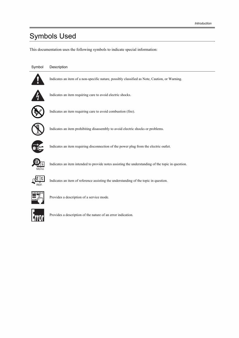
Symbols Used
This documentation uses the following symbols to indicate special information:
Symbol Description
Indicates an item of a non-specific nature, possibly classified as Note, Caution, or Warning.
Indicates an item requiring care to avoid electric shocks.
Indicates an item requiring care to avoid combustion (fire).
Indicates an item prohibiting disassembly to avoid electric shocks or problems.
Indicates an item requiring disconnection of the power plug from the electric outlet.
Indicates an item intended to provide notes assisting the understanding of the topic in question.
Indicates an item of reference assisting the understanding of the topic in question.
Provides a description of a service mode.
Provides a description of the nature of an error indication.
Memo
REF.

Introduction
The following rules apply throughout this Service Manual:1. Each chapter contains sections explaining the purpose of specific functions and the relationship between electrical
and mechanical systems with reference to the timing of operation.
In the diagrams, represents the path of mechanical drive; where a signal name accompanies the symbol ,
the arrow indicates the direction of the electric signal.
The expression "turn on the power" means flipping on the power switch, closing the front door, and closing thedelivery unit door, which results in supplying the machine with power.
2. In the digital circuits, '1'is used to indicate that the voltage level of a given signal is "High", while '0' is used toindicate "Low".(The voltage value, however, differs from circuit to circuit.) In addition, the asterisk (*) as in"DRMD*" indicates that the DRMD signal goes on when '0'.
In practically all cases, the internal mechanisms of a microprocessor cannot be checked in the field. Therefore, theoperations of the microprocessors used in the machines are not discussed: they are explained in terms of fromsensors to the input of the DC controller PCB and from the output of the DC controller PCB to the loads.
The descriptions in this Service Manual are subject to change without notice for product improvement or otherpurposes, and major changes will be communicated in the form of Service Information bulletins.All service persons are expected to have a good understanding of the contents of this Service Manual and all relevantService Information bulletins and be able to identify and isolate faults in the machine."

Contents
Contents
第 1 章 Installation Procedure
1.1 Points to Note About Installation .......................................................................................................................... 21.1.1Precaution for installation ............................................................................................................................... 2
1.2 Checking components ........................................................................................................................................... 31.2.1Checking the Contents..................................................................................................................................... 3
1.3 Installation procedure ............................................................................................................................................ 51.3.1Installation ....................................................................................................................................................... 5

Contents

Chapter 1 Installation Procedure
Chapter 1
2
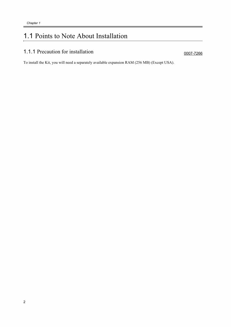
1.1 Points to Note About Installation
1.1.1 Precaution for installation 0007-7266
To install the Kit, you will need a separately available expansion RAM (256 MB) (Except USA).
Chapter 1
3
1.2 Checking components
1.2.1 Checking the Contents 0007-7268
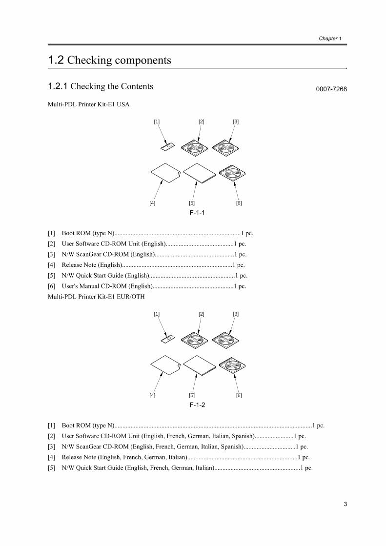
Multi-PDL Printer Kit-E1 USA
F-1-1
[1] Boot ROM (type N)..............................................................................1 pc.[2] User Software CD-ROM Unit (English)..........................................1 pc.[3] N/W ScanGear CD-ROM (English).................................................1 pc.[4] Release Note (English)....................................................................1 pc.[5] N/W Quick Start Guide (English).....................................................1 pc.
[6] User's Manual CD-ROM (English)..................................................1 pc.Multi-PDL Printer Kit-E1 EUR/OTH
F-1-2
[1] Boot ROM (type N)..........................................................................................................................1 pc.
[2] User Software CD-ROM Unit (English, French, German, Italian, Spanish)........................1 pc.[3] N/W ScanGear CD-ROM (English, French, German, Italian, Spanish)................................1 pc.[4] Release Note (English, French, German, Italian)....................................................................1 pc.[5] N/W Quick Start Guide (English, French, German, Italian).....................................................1 pc.
[1] [2] [3]
[5][4] [6]
[1] [2] [3]
[5][4] [6]

4
[6] User's Manual CD-ROM (English, French, German, Italian)..................................................1 pc.

Chapter 1
5
1.3 Installation procedure
1.3.1 Installation 0007-7276
1. Turning Off the Host Machine
Before starting the work, be sure to perform thefollowing on the host machine in strict order:1. Hold down on the control panel power switch for3 sec or more.2. Go through the instructions indicated on thecontrol panel touch panel (for shutdown sequence)so that the host machine's main power switch maybe turned off.3. Turn off the main power switch.4. Disconnect the power cable (from the walloutlet).
F-1-3
2. Installation1) Remove the 4 screws [1].2) Loosen the 2 screws [2].
F-1-4
3) Pull the face cover [1] in upward direction todetach.
F-1-5
4) Push the locking lever [1] to detach the bootROM [2].
F-1-6
[4][3][2]
[1]
ON/OFF
[1]
[1]
[2]
[1]
Chapter 1
6
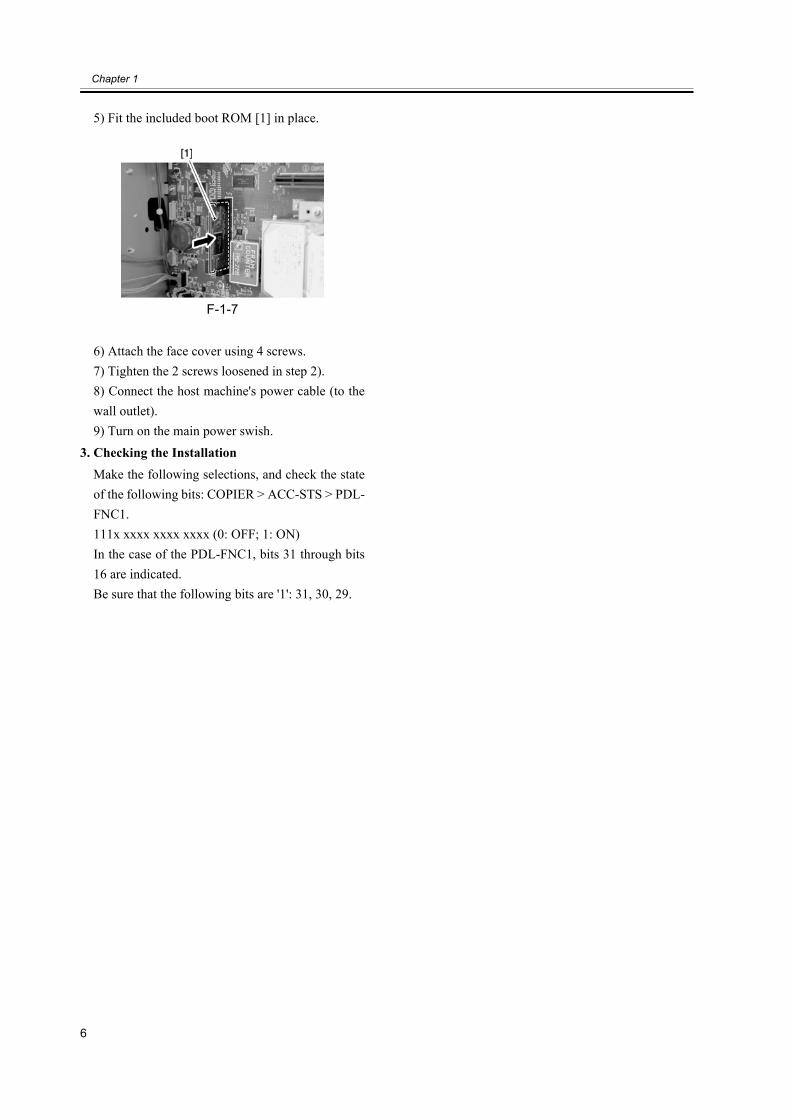
5) Fit the included boot ROM [1] in place.
F-1-7
6) Attach the face cover using 4 screws.7) Tighten the 2 screws loosened in step 2).8) Connect the host machine's power cable (to thewall outlet).9) Turn on the main power swish.
3. Checking the InstallationMake the following selections, and check the stateof the following bits: COPIER > ACC-STS > PDL-FNC1.111x xxxx xxxx xxxx (0: OFF; 1: ON)In the case of the PDL-FNC1, bits 31 through bits16 are indicated.Be sure that the following bits are '1': 31, 30, 29.

Oct 26 2004
