multi-objective optimization of sensor quality with efcient marine vehicle...
TRANSCRIPT
Multi-objective Optimization of Sensor Quality withEfficient Marine Vehicle Task Execution
Michael BenjaminNAVSEA Division Newport RICSAIL, MIT Cambridge MAe–mail: [email protected]
Matthew GrundWoods Hole Oceanographic Institution
Advanced Engineering LaboratoryWoods Hole, MA 02543
e–mail: [email protected]
Paul NewmanRobotics Research Group
Oxford University, UKe–mail: [email protected]
Abstract— This paper describes the in-field operation of twointeracting autonomous marine vehicles to demonstrate thesuitability of Interval Programming (IvP), a novel mathematicalmodel for multiple-objective optimization. Broadly speaking,IvP coordinates competing control needs such as primary taskexecution that depends on a sufficient position estimate, andvehicle maneuvers that will improve that position estimate. In thiswork, vehicles cooperate to improve their position estimates usinga sequence of vehicle-to-vehicle range estimates from acousticmodems. Coordinating primary task execution and sensor qualitymaintenance is a ubiquitous problem, especially in underwatermarine vehicles. This work represents the first use of multi-objective optimization in a behavior-based architecture to addressthis problem.
I. INTRODUCTION
This work posits a solution to the problem of controllingan autonomous marine vehicle where control requirements areconflicted between primary task execution and maintaining asufficiently accurate position estimate to facilitate primary taskexecution.
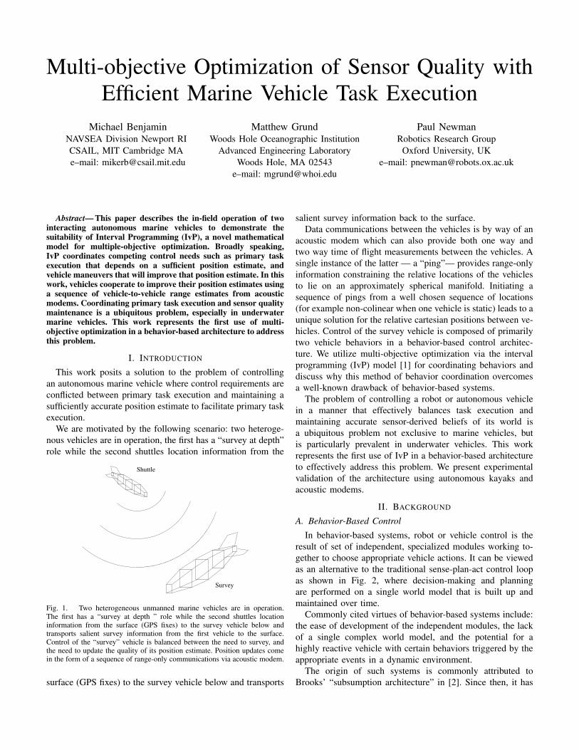
We are motivated by the following scenario: two heteroge-nous vehicles are in operation, the first has a “survey at depth”role while the second shuttles location information from the
Survey
Shuttle
Fig. 1. Two heterogeneous unmanned marine vehicles are in operation.The first has a “survey at depth ” role while the second shuttles locationinformation from the surface (GPS fixes) to the survey vehicle below andtransports salient survey information from the first vehicle to the surface.Control of the “survey” vehicle is balanced between the need to survey, andthe need to update the quality of its position estimate. Position updates comein the form of a sequence of range-only communications via acoustic modem.
surface (GPS fixes) to the survey vehicle below and transports
salient survey information back to the surface.Data communications between the vehicles is by way of an
acoustic modem which can also provide both one way andtwo way time of flight measurements between the vehicles. Asingle instance of the latter — a “ping”— provides range-onlyinformation constraining the relative locations of the vehiclesto lie on an approximately spherical manifold. Initiating asequence of pings from a well chosen sequence of locations(for example non-colinear when one vehicle is static) leads to aunique solution for the relative cartesian positions between ve-hicles. Control of the survey vehicle is composed of primarilytwo vehicle behaviors in a behavior-based control architec-ture. We utilize multi-objective optimization via the intervalprogramming (IvP) model [1] for coordinating behaviors anddiscuss why this method of behavior coordination overcomesa well-known drawback of behavior-based systems.
The problem of controlling a robot or autonomous vehiclein a manner that effectively balances task execution andmaintaining accurate sensor-derived beliefs of its world isa ubiquitous problem not exclusive to marine vehicles, butis particularly prevalent in underwater vehicles. This workrepresents the first use of IvP in a behavior-based architectureto effectively address this problem. We present experimentalvalidation of the architecture using autonomous kayaks andacoustic modems.
II. BACKGROUND
A. Behavior-Based Control
In behavior-based systems, robot or vehicle control is theresult of set of independent, specialized modules working to-gether to choose appropriate vehicle actions. It can be viewedas an alternative to the traditional sense-plan-act control loopas shown in Fig. 2, where decision-making and planningare performed on a single world model that is built up andmaintained over time.
Commonly cited virtues of behavior-based systems include:the ease of development of the independent modules, the lackof a single complex world model, and the potential for ahighly reactive vehicle with certain behaviors triggered by theappropriate events in a dynamic environment.
The origin of such systems is commonly attributed toBrooks’ “subsumption architecture” in [2]. Since then, it has
World
Model
plan
Behavior
Behavior
Behavior
World
sense act sense act
actionselection
Fig. 2. Behavior-based control differs from conventional control by com-posing overall vehicle behavior into distict modules that are developed andoperate largely in isolation, and coordinated through an action selectionmechanism. In this case, action selection is in the form of a new multi-objective optimization technique to overcome known difficulties associatedwith behavior-based control.
been used in a large variety of applications including: indoorrobots, e.g., [3], [4], [5], [6], [7], [8], [9], [10], [11], landvehicles, e.g., [12], planetary rovers, e.g., [13], [14], [15], andmarine vehicles, e.g., [16], [17] [18], [19], [20], [21], [22].
Action selection, as indicated in Fig. 1, is the process ofchoosing a single action for execution, given the outputs ofthe behaviors. The “action space” is the set of all possibledistinct actions. For example, all combinations of rotationaland angular velocity for a robot, or all speed, heading anddepth combinations for a marine vehicle.
B. Known Difficulties in Behavior-Based Control
The primary difficulty often associated with behavior-basedcontrol concerns action selection - namely how to ensure thechosen action really is in the best overall interest of the robotor vehicle. An action generally is a vector of values, one foreach actuator being controlled. For example, the rotational andangular velocity for a land robot, or heading, speed and depthfor a marine robot.
Generally there are two techniques used in practice. Thesimplest method is to pick (at every iteration of the controlloop) a single behavior to have exclusive control of the vehicle.Some approaches, like [18], [2], [23] assign a set of fixedpriorities to behaviors, and conditions for their activation. Thepriorities do not change dynamically. In other implementa-tions, like [20], priorities may be determined dynamically.Although appealing due to its simplicity, it is problematic inapplications where the outright ignoring of the “secondary”behaviors leads to gross vehicle inefficiency, as is the situationwith task described in this work.
The other common form of action selection, known variablyas “action averaging”, “vector summation” etc., takes theoutput of each behavior in the form of a vector and uses theaverage numerical value as the action sent to the vehicle’sactuators. Summation is typically weighted to reflect behaviorpriority. This method has been used effectively in a numberof applications, [3], [24], [25], [19], [26].
When the preferred actions of two distinct behaviors dis-agree, this approach rests on the idea that the alternative ac-tions degrade in effectiveness in a manner depicted in Fig.3. Insuch a case, the action, or actuator setting, in between the twoindividually preferred actions may indeed be the most effective
Util
ity
Best action for Behavior B
Best action for Behavior A
Combined effectiveness
two actionsAverage of best
Possible settings for a single actuator
Fig. 3. In action-averaging, each behavior outputs a single best action. Thebest action presumably is the most effective among alternative actions for thatparticular behavior. The effectiveness levels of alternative actions are renderedhere only for illustration and do not participate in the action averaging process.When two behaviors are non-mutually exclusive and share common actionchoices with high levels of effectiveness, as shown here, then action averagingtypically reflects an appropriate compromise between behaviors.
action overall. However, action averaging is problematic incases when alternative actions degrade in effectiveness in amanner depicted in Fig. 4, where the numerical average doesnot represent an effective compromise between two behaviorsthat are, in effect, mutually exclusive.
Util
ity
Best action for Behavior B
Best action for Behavior A two actions
Avg of best
Possible settings for a single actuator
Fig. 4. The average of the best action produced by two behaviors mayhave poor value for both behaviors. The chooser of the action is obliviousto the error since the behaviors output a single preferred action and notcommunicated the underlying effectiveness of their alternatives, rendered hereonly for illustration. In this case, the interests being pursued by the twobehaviors are mutually exclusive, and the “compromise” is detrimental toboth.
Even in cases where two behaviors are not mutually ex-clusive, where there do indeed exist actions that represent agood compromise, as shown in Fig. 5, action averaging cannot guarantee the selection of the right action.
In this work, such situations are typical between vehiclebehaviors, and a new method of multi-objective optimizationis applied to action selection to overcome this problem.
III. THE “IVP” ARCHITECTURE
Here we describe the use of multi-objective optimizationwith interval programming and the two primary behaviors usedin this experiment comprising task execution and maneuversto update vehicle position estimate.
A. Behavior-Based Control with Interval Programming
By using multi-objective optimization in action selection,behaviors produce an objective function rather than a singlepreferred action ( [7], [12]). In the examples in Figs. 3 through5, the objective functions are what distinguish opportunities forcompromise. Note the pair of preferred actions in Figs. 3 and

Util
ity
Best action for Behavior A
Best action for Behavior B
Nearly bestfor B
two actionsAvg of best
A goodcompromise
Possible settings for a single actuator
Fig. 5. A multi-modal behavior is one where alternative actions exist thathave high utility but actions “in between” have lower utility. For example abehavior where turning hard left or right is useful, but going straight is bad.In such situations, if only the single best action from each behavior is output,opportunities for effective compromise between two non-mutually exlusivebehaviors is missed by simply averaging the two elite actions.
4 are virtually the same despite the differences in utility ofsecondary alternatives.
There are two practical challenges in handling objectivefunctions: (1) the method must be fast enough to accommodatethe vehicle control loop, typically 1-20Hz. On each iterationnew functions are created and a new problem solved (speedis a primary advantage of action averaging). (2) the methodcannot be overly restrictive on objective function form. Non-convex, multi-modal functions are quite common.
The IvP model specifies (1) a scheme for representingfunctions of unlimited form and (2) a set of algorithms forfinding the globally optimal solution. All functions are piece-wise linearly defined, thus they are typically an approximationof a behavior’s true underlying utility function. Search is overthe weighted sum of individual functions and uses branchand bound to search through the combination space of piecesrather than the decision space of actions. The only errorintroduced is in the discrepancy between a behavior’s trueunderlying utility function and the piecewise approximationproduced to the solver. This error is preferable compared withthe error of restricting all behaviors to a quadratic functionfor example. Furthermore, the search is much faster than bruteforce evaluation of the decision space, as done in [12]. Thedecision regarding function accuracy is a local decision tothe behavior designer, who typically has insight into what issufficient. The solver guarantees a globally optimal solutionand this work validates that such search is feasible in a vehiclecontrol loop of 4Hz on a 600MHz computer.
To enhance search speed, the initial decision provided tothe branch and bound algorithm is the output of the previouscycle, since typically what was a good thing to do a fractionof a second prior, is not a bad thing at the present. (In fact,when something does change dramatically in the world, suchas hitting a way-point, the solve time has been observed tobe roughly 50% longer, but still comfortably under practicalconstraints).
B. Behavior for Executing a Survey Task
The survey behavior drives the vehicle to a sequence of way-points at a preferred speed. The produced objective function
ranks candidate maneuvers with a utility that degrades lin-early w.r.t. the candidate maneuver’s delta from the preferredheading and speed, as shown in Fig. 6. When this behavior is
Fig. 6. The survey behavior produces an objective function with peak utilitiesat the preferred heading and speed that would result in a traversal to the nextarea of interest in the survey. The utilities degrade linearly with the delta of acandidate decision. The utility function is parameterizable at mission planningtime. The function is produced from scratch at each iteration of the controlloop to reflect the new relative position of the vehicle to the area of interestin the survey.
run in isolation, it results in an un-conflicted set of maneuverlegs comprising a survey as shown in Fig. 7. This particularsurvey mission pattern also represents the survey executed inour experimental results (alongside another behavior) shownin Fig. 8.
PIER
Fig. 7. The survey behavior, if run in isolation, will execute a series oflegs governed by a set of way-points. The prevailing objective function rankscandidate maneuvers based on the next way-point. The objective function isshown here defined over candidate heading and speed where the darker pointsrepresent more preferred decisions.

C. Behavior for Resolving Position Uncertainty
We now describe the design and implementation of abehavior that ensures spatial diversity of ping-locations (thelocations from which acoustic range information is requestedvia the acoustic modems). The goal is to enable the surveyvehicle to gather enough information to locate (from a leastsquares adjustment or otherwise on a bundle of range mea-surements) the nav-aid vehicle which may or may not bemoving. Using the entirety of the recorded ping-set is not areasonable option given the latter possibility. This motivatesmaking decisions in the light of a previous/local ping history.We label the set of the last n locations (out of N total pings)at which range information was recorded between the twovehicles ΩT
n = [XNXN−1 · · ·XN−n]T . We are now facedwith deciding where the next ping should occur from. This isa function of the shape of the locations in Ωn both in termsof their collective spatial extent and diversity. Consider, forexample, the case where the points in Ωn form a line. It maybe that this line is generally broadside to the nav-aid vehicleand naturally yields a tight solution. However a trajectorybroadly co-linear with the nav-aid vehicle will lead to a poorlyconstrained solution. We adopt a motion governing behaviorthat seeks to produce spatially diverse set of measurementorigins. The idea is to examine the principal directions of atentative point set,Ωn′ , formed by augmenting Ωn with a newtentative observation point XN+1. We proceed by forming the2 × 2 covariance matrix , C, of this point set and define theminimum and maximum eigen-values of C as λ− and λ+
respectively. The condition number of C, the ratio λ−
λ+ , is anindication of the circular symmetry of Ωn′ — being unityfor a perfect circle and zero for a perfectly co-linear pointset. We also wish to take into account the size, or spatialextent of the point set. Consider the case where Ωn′ is small,almost round cluster (close to coincident) we do not wishto place a high utility in choosing a new putative observingpoint that would invoke no or little change in view point evenif it would result in a Ωn′ with polar symmetry. Instead wewould prefer to undertake a significant excursion away fromthe original cluster despite the resulting reduction in λ
−
λ+ . Weencapsulate this preference by weighting the ratio λ
−
λ+ by asigmoid function. This leads us to an expression of the utilityu(XN+1) of visiting a new point XN+1 = (xN+1, yN+1)given a recent history of N measurement locations ΩN :
u(XN+1) =λ−
λ+tanh(
λ+− α
β) (1)
here α and β parameterize the “break point” and knee widthof the sigmoid function respectively. The experimental resultspresented in this paper use marine surface craft, so Ω hasso far been considered to be set of 2D points. HoweverEquation 1 is equally applicable to the 3D x, y, z measurementpositions that result from Autonomous Underwater Vehicle(AUV) operations.
300 320 340 360 380 400 420 440 460 480 500
−60
−40
−20
0
20
40
60
80
100
120
0
0.1
0.2
0.3
0.4
0.5
0.6
0.7
0.8
0.9
1
300 320 340 360 380 400 420 440 460 480 500
−60
−40
−20
0
20
40
60
80
100
120
Fig. 8. The contours of the utility surface (in xy-space) of obtaining a new“ping” from a new location conditioned on two illustrative distributions ofprevious “ping” locations. The linear distributions on the left produces twosymmetric peaks. Moving to either one would substantially increase the spatialdiversity and importantly resolve potential left/right ambiguity resulting fromlinear motion with range only measurements. The circular distribution on inthe right hand plot yields a polar-symmetric utility surface - no one directionis preferred over another any substantial (but not excessive) radial motion willsatisfy the desire to range from a maximally spatial diverse set of locations
IV. THE EXPERIMENT SETUP
For experimental validation of the architecture two au-tonomous kayaks fitted with acoustic modems were used.
A. Behavior Configuration
The two behaviors described in the previous section wereconfigured in a manner that retained a steady priority weightfor the survey behavior, and a varying priority weight for thebehavior for resolving position uncertainty. When the positionuncertainty became higher, the “resolve” behavior grew inpriority until the vehicle sufficiently maneuvered to reduceuncertainty via an acoustic modem communication.
B. Acoustic Communication and Acoustic Telemetry
Fig. 9. Basic WHOI Micro-modem board set: power amp and main board.In this simple low-power configuration, the modem communicates usingFrequency-Hopping Frequency Shift Keying (FH-FSK) at a burst rate of80bps. At 25KHz, the modem can communicate at ranges greater than 2km,in the challenging Very Shallow Water environment.
The autonomous vehicles are equipped with WHOI Micro-modems which can provide acoustic telemetry and ranging.The modem is a small low-power design based around the

TABLE IWHOI MICRO-MODEM SPECIFICATIONS
Spec. Description Units
PRX Power consumption while receiving 80 mW
PTX Power consumption while transmitting 10 W
SPLTX Transmitter sound pressure level 192 dB re µ Pa
∆TRX Receiver timing resolution 125 µ sec
rFSK FSK data rate 80 bps
BFSK FSK packet data payload 32 bytes
TFSK FSK packet duration 3.2 seconds
Nnodes Maximum number of nodes per subnet 16 nodes
fc Band C center frequency 25KHz
BWc Band C Bandwidth 4 KHz
Texas Instruments TMS320C5416 fixed-point DSP, as shownin Fig. 9. The Micro-modem was designed for autonomousvehicles and long term sub-sea deployed systems [27]. Itsspecifications are summarized in table I.
The modem provides access to a half-duplex underwa-ter acoustic channel using a time-domain multiple access(TDMA) scheme [28]. Telemetry packet transmissions arescheduled using a short (1.1 second duration) cycle ini-tialization (CI) packet, followed shortly thereafter with alonger telemetry packet. Typically, one modem implementsa schedule by transmitting CI packets, and all modems in thesubnet observe the schedule, transmitting their telemetry whencommanded, and receiving otherwise. This allows modemusers to share their telemetry across the acoustic subnet, insynchronized broadcast fashion.
Because telemetry packets have small (32 byte) data pay-loads, a library of compressed binary messages called theCompact Control Language (CCL) has been developed [29].This library has been expanded to include a UTM navigationmessage, for transmitting high precision vehicle location in-formation to another platform. This new CCL message wasused to convey the “shuttle” kayak’s position estimate to the“survey” kayak.
In addition, the Micromodem is capable of acoustic naviga-tion. Networks of acoustic transponders can be interrogated,estimating range via travel-time measurements, and modemscan estimate range to each other, using an acoustic networkping packet. In this experiment, short ping packets (also 1.1second duration) were used to estimate range between theautonomous kayaks.
C. The Marine Vehicle Platforms
Experimental validation is done on four kayak-based au-tonomous surface crafts depicted in Fig. 10. See [30] for moredetails on this platform.
V. EXPERIMENTAL RESULTS
Two Kayaks, fitted with acoustic modems were used togenerate the results in this section. One vehicle which willultimately play the role of the nav-aid vehicle remained still
Kill Switch
802.11b Antenna
Cool Water CirculatedCooling System
Main vehicle computerin Watertight Enclosure
Fig. 10. A kayak-based autonomous surface craft.
at the origin while the other took the role of the surveyvehicle. The latter executed a trajectory determined by theinterplay of two, sometimes contradictory behaviors, describedin Sections III-B and III-C — the desire to execute a simplesurvey pattern (in this case a “box”) and also the desire toadd spatial diversity to the locations from which vehicle tovehicle ranging occurs. The latter “resolve” behavior runningon the survey vehicle is modulated by a quality metric, η, of itsown onboard navigation. In the field this may be for examplehorizontal dilution of precision (HDOP) or the volume of its 1-sigma position uncertainty ellipsoid. When the quality metricis low, greater importance is attached to obtaining a nav-fixby ranging to and communicating with the nav-aid vehicle.However, to obtain such a fix while avoiding the singularconfigurations and left-right ambiguities that plague range-only estimation, spatial diversity is required - precisely whatthe “resolve” behavior was designed to instigate. In Figure 11we paint the trajectory of the vehicle with color to denote theonboard navigation quality metric. Blue and red represent highand low navigational confidence respectively which accord lowand high importance to the resolve behavior. In short, when thetrajectory is shaded red the motivation to execute a “wiggle”is increased over that when it is blue. The experimental arena(a large river) was not sufficiently large to allow a genuinedegradation of navigation to accumulate over time. Insteadthe evolution η was simulated by a zero to unity ramp with aperiod of 60 seconds. Although crude, this approach does aidclarity while illustrating the efficacy of the IvP framework interms of action selection. In particular the importance attacheda particular behavior is not coupled to the effect it has on thesystem at large which would be the case if the resolve behaviorreally had an effect on η.
Around the perimeter of Figure 11 a selection of utilitysurfaces are rendered. Each depicts the utility associated withachieving one more ping from a x, y position conditionedupon the set of locations from which the survey vehicle hasrecently pinged the stationary nav-aid vehicle. The recent pinglocations are shown as white dots superimposed over the utilitysurfaces. Note how the value of η modulates the overall utility.For example at point 20 the utility of a course change todiversify ping-locations is small because the vehicle possessesa high degree of confidence in its position estimates. on theother hand at point 17 the converse is true and we see aperturbation occurring in the ensuing vehicle path. The straightline in the south east corner is a result of an extended periodof failed acoustics. With so few recent ping-locations pingingfrom anywhere results in significant spatial diversity and sothe vehicle simply executes the unadulterated baseline surveybehavior without perturbation.
VI. CONCLUSIONS
In this work we have applied a novel method for executingmulti-objective optimization on a marine vehicle platform andshown its suitability in resolving conflicts between sensorrequirements and primary task completion in the marineenvironment. Although this work has demonstrated that asensor optimization behavior and survey behavior can bothbe satisfied, much practical work remains to implement arobust solution for underwater vehicles operating in the oceanenvironment. For example, underwater survey sensors suchas sidescan sonars and cameras have different behavioralconstraints from the survey behavior presented here. Also,the navigation sensor optimization behavior should rely onobserved variables such as acoustic link quality, and navigationsolution quality estimates.
ACKNOWLEDGEMENTS
The WHOI acoustic modem navigation capabilities weredeveloped under the U.S Office of Naval Research AOFNCprogram, contract number No. N00014-02-C-0201 managedby Jim Valentine and Tom Curtin. This work was fundedin part by ONR NICOP Program, contract No. N00014-05-10311 managed by Donald Wagner and Jim Greenberg, as wellas by the NUWC Division Newport ILIR program managedby Dick Philips. The authors also wish to thank Joe Curcio,the designer and builder of the kayak platforms used in ourexperiments, and John Leonard and Lee Freitag for support inthis cross-discipline venture.
REFERENCES
[1] M. R. Benjamin, “The Interval Programming Model for Multi-ObjectiveDecision Making,” Computer Science and Artificial Intelligence Labo-ratory, MIT, Cambridge, MA, Tech. Rep. AIM-2004-021, September2004.
[2] R. A. Brooks, “A Robust Layered Control System for a Mobile Robot,”IEEE Journal of Robotics and Automation, vol. RA-2, no. 1, pp. 14–23,April 1986.
[3] R. C. Arkin, “Motor Schema Based Navigation for a Mobile Robot: AnApproach to Programming by Behavior,” in Proceedings of the IEEEConference on Robotics and Automation, Raleigh, NC, 1987, pp. 264–271.
[4] R. C. Arkin, W. M. Carter, and D. C. Mackenzie, “Active Avoidance:Escape and Dodging Behaviors for Reactive Control,” InternationalJournal of Pattern Recognition and Artificial Intelligence, vol. 5, no. 1,pp. 175–192, 1993.
[5] J. Hoff and G. Bekey, “An Architecture for Behavior CoordinationLearning,” in Proceedings of the 1995 IEEE International Conferenceon Neural Networks, Perth, Australia, November 1995, pp. 2375–2380.
[6] S. Lenser, J. Bruce, and M. Veloso, “A Modular Hierarchical Behavior-Based Architecture,” in RoboCup-2001: The Fifth RoboCup Competi-tions and Conferences, A. Birk, S. Coradeschi, and S. Takokoro, Eds.Springer Verlag, 2002.
[7] P. Pirjanian, “Multiple Objective Action Selection and Behavior Fusion,”Ph.D. dissertation, Aalborg University, 1998.
[8] J. Riekki, “Reactive Task Execution of a Mobile Robot,” Ph.D. disser-tation, Oulu University, 1999.
[9] A. Saffiotti, E. H. Ruspini, and K. Konolige, “Using Fuzzy Logic forMobile Robot Control,” in Practical Applications of Fuzzy Technologies,H. J. Zimmerman, Ed. Kluwer Academic Publishers, 1999, ch. 5, pp.185–206.
[10] E. Tunstel, “Coordination of Distributed Fuzzy Behaviors in MobileRobot Control,” in IEEE International Conference on Systems, Man, andCybernetics, Vancouver, BC, Canada, October 1995, pp. 4009–4014.
[11] M. Veloso, E. Winner, S. Lenser, J. Bruce, and T. Balch, “Vision-servoed Localization and Behavior-Based Planning for an AutonomousQuadruped Legged Robot,” in Proceedings of AIPS-2000, Breckenridge,April 2000.
[12] J. K. Rosenblatt, “DAMN: A Distributed Architecture for MobileNavigation,” Ph.D. dissertation, Carnegie Mellon University, Pittsburgh,PA, 1997.
[13] H.-H. Ju, P.-Y. Cui, and H.-T. Cui, “Autonomous Behavior Path Planningfor Lunar Rover,” ACTA AUTOMATICA SINICA, vol. 29, no. 2, pp. 324–329, 2002.
[14] P. Pirjanian, T. L. Huntsberger, and P. S. Schenker, “Development ofCAMPOUT and its further applications to planetary rover operations:a multi-robot control architecture,” in Proceedings of SPIE Conferenceon Sensor Fusion and Decentralized Control in Robotic Systems IV,Newton, MA, October 2001.
[15] S. Singh, R. Simmons, T. Smith, A. Stentz, V. Verma, A. Yahja, andK. Schwehr, “Recent Progress in Local and Global Traversability forPlanetary Rovers,” in IEEE Conference on Robotics and Automation,San Francisco, CA, April 2000.
[16] M. R. Benjamin, “Multi-objective Autonomous Vehicle Navigation inthe Presence of Cooperative and Adversarial Moving Contacts,” inOCEANS 2002, Biloxi Mississippi, October 2002.
[17] M. Benjamin, J. Curcio, J. Leonard, and P. Newman, “Navigationof Unmanned Marine Vehicles in Accordance with the Rules of theRoad,” in International Conference on Robotics and Automation (ICRA),Orlando, Florida, May 2006.
[18] A. A. Bennet and J. J. Leonard, “A Behavior-Based Approach to Adap-tive Feature Detection and Following with Autonomous UnderwaterVehicles,” IEEE Journal of Oceanic Engineering, vol. 25, no. 2, pp.213–226, April 2000.
[19] M. Carreras, J. Batlle, and P. Ridao, “Reactive Control of an AUVUsing Motor Schemas,” in International Conference on Quality Control,Automation and Robotics, Cluj Napoca, Rumania, May 2000.
[20] R. Kumar and J. A. Stover, “A Behavior-Based Intelligent ControlArchitecture with Application to Coordination of Multiple UnderwaterVehicles,” IEEE Transactions on Systems, Man, and Cybernetics - PartA: Cybernetics, vol. 30, no. 6, pp. 767–784, November 2001.
[21] J. K. Rosenblatt, S. B. Williams, and H. Durrant-Whyte, “Behavior-Based Control for Autonomous Underwater Exploration,” InternationalJournal of Information Sciences, vol. 145, no. 1-2, pp. 69–87, 2002.
[22] S. B. Williams, P. Newman, G. Dissanayake, J. K. Rosenblatt, andH. Durrant-Whyte, “A decoupled, distributed AUV control architecture,”in Proceedings of 31st International Symposium on Robotics, Montreal,2000.
[23] P. M. Newman, “MOOS - A Mission Oriented Operating Suite,” MITDepartment of Ocean Engineering, Tech. Rep. OE2003-07, 2003.
[24] R. C. Arkin and T. Balch, “AuRA: Principles and Practice In Review,”Journal of Experimental and Theoretical Artificial Intelligence, vol. 9,pp. 175–189, 1997.
[25] T. Balch and R. C. Arkin, “Behavior-Based Formation Control for Mul-tiagent Robot Teams,” IEEE Transactions on Robotics and Automation,December 1998.

Fig. 11. A rendering of the experimental results. The vehicle (an autonomous Kayak see Figure 10) executes a meandering trajectory under the influence oftwo behaviors running in the IvP framework. One behavior is set on marshalling the vehicle around a rectangular survey pattern similar to that in Figure 7. Thesecond behavior is more complex. It continually considers the spatial diversity of the most recent sites from which acoustic ranges to the companion vehicleare obtained. In the light of this it produces a utility or objective function over (x,y) space (which is later mapped to the course, speed and time action space)scored in proportion to the degree of increase spatial diversity which be afforded by acquiring a new range measurement at each x, y location. A few examplesof the utility functions generated at various times around the circuit are plotted in independent axes around the perimeter. The overall weight/importance ofthe behavior is mediated by the confidence the vehicle has in its own navigation. In this way, when unsure of its own position the vehicle is motivated tomove in a way to increase the quality of a navigation update from the nav-aid vehicle sitting at the origin. The vehicle trajectory is colored in proportion tothis confidence metric — blue high, red low. The straight section in the south east corner is due to a temporary drop in the rate of successful two way rangemeasurements - with so few recent ping locations any motion produces spatial diversity and the preferred linear motion of the survey behavior is un-opposed.
[26] O. Khatib, “Real-Time Obstacle Avoidance for Manipulators and MobileRobots,” in Proceedings of the IEEE International Conference onRobotics and Automation, St. Louis, MO, 1985, pp. 500–505.
[27] L. Freitag, M. Grund, S. Singh, J. Partan, and K. Ball, “The WHOIMicro-Modem: An Acoustic Communications and Navigation Systemfor Multiple Platforms,” in IEEE OCEANS, Washington DC, 2005.
[28] L. Freitag, M. Johnson, and M. Grund, “Integrated Acoustic Communi-cation and Navigation for Multiple AUVs,” in IEEE OCEANS, Honolulu,October 2001, pp. 2065–2070.
[29] R. P. Stokey, “A Compact Control Language for Autonomous Underwa-ter Vehicles,” Woods Hole Oceanographic Institution, Tech. Rep., 2005.
[30] J. Curcio, J. Leonard, and A. Patrikalakis, “SCOUT - A Low CostAutonomous Surface Platform for Research in Cooperative Autonomy,”in OCEANS 2005, Washington DC, September 2005.