multi-max f1000 / f2000 - espar of michigan options and... · multi-max f1000 / f2000 wiring - pin...
TRANSCRIPT

3
4
3
4
1
5
2
5
1
Multi-Max F1000 / F2000
WIRING - PIN CONNECTIONS
CONTROLLER
EXTERNAL CONTROL WIRES
Remote Control Input - Devices with the optional remote control input may be started by applying power to “External Control” wire. Same run time limit as for the manual start will be applied.
Status Control Output - Devices with the optional Status Monitor output produce output signal displaying if the heater runs normally (based on diagnostic codes read from the heater)
PROGRAMMING THE HEATER
Setup configuration is kept in configuration files stored on the SD card. User must use ESPAR software to create configuration files. For convenience the files keep information in readable format but they are sensitive to spaces and length of each line and also not all possible combinations of settings are allowed, so even though they can be edited manually, use of ESPAR programmer is needed to avoid unpredictable results.
WARNING!:Use Espar program which is included on the supplied SD Card to avoid unpredictable results.
When running the program, it will give you a WELCOME SCREEN before going to the main Menu.
Side View Cable Entry View
WARNING!:Use caution when connecting the wires to avoid damage to controller.Multi-max shouldn’t be connected to any air heater control harness.
There are four (4) Tabs in the program namely: Heater Start Events,Skip Scheduler, Control Features and Alert and Control Date and Time.
REFERENCE GUIDEMulti-Max controller series is an advanced timer featured with real time clock/calendar (RTCC), SD card, temperature sensors and a LCD (F2000).
COMPONENTS
1 LED
2 LCD
3 SD CARD SLOT
4 RESET
5 BUTTONS
P/N: 20 2800 70 16 00 P/N: 20 2800 70 17 00
Espar Products, Inc.
(800) 387-4800(905) 670-0960(905) 670-0728 Fax
Yellow/Violet or Violet Connect to pin 4
Black/Red or Black Connect to pin 5
Red Connect to pin 1 Red,+ PowerYellow Connect to pin 2 Yellow, ON/OFFBrown/White Connect to pin 3 Brown/White Ground Reference Optional Remote Control Input Yellow/Violet or Violet Optional Status Control Output Black/Red or BlackBlue/White Connect to pin 6 Blue/White Diagnostic
Subject to change without notice 08/20131
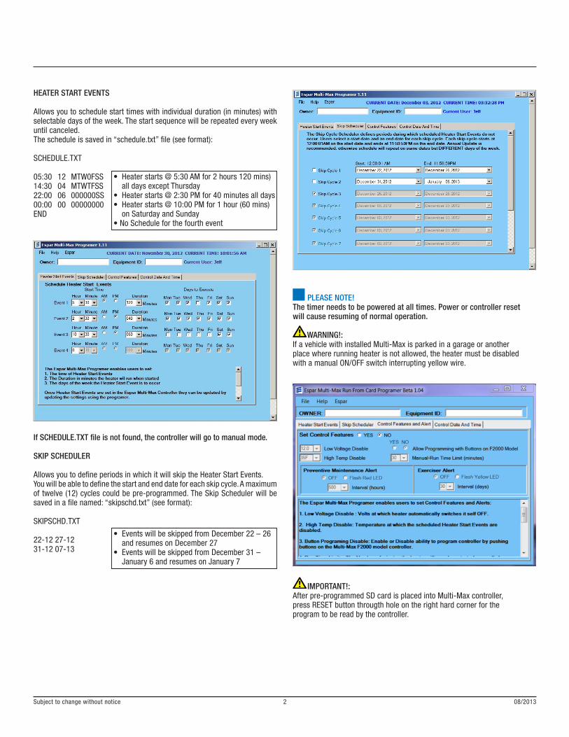
HEATER START EVENTS
Allows you to schedule start times with individual duration (in minutes) with selectable days of the week. The start sequence will be repeated every week until canceled.The schedule is saved in “schedule.txt” file (see format):
SCHEDULE.TXT
05:30 12 MTW0FSS14:30 04 MTWTFSS22:00 06 000000SS00:00 00 00000000END
If SCHEDULE.TXT file is not found, the controller will go to manual mode.
SKIP SCHEDULER
Allows you to define periods in which it will skip the Heater Start Events.You will be able to define the start and end date for each skip cycle. A maximum of twelve (12) cycles could be pre-programmed. The Skip Scheduler will be saved in a file named: “skipschd.txt” (see format):
SKIPSCHD.TXT
22-12 27-1231-12 07-13
PLEASE NOTE! The timer needs to be powered at all times. Power or controller resetwill cause resuming of normal operation.
WARNING!:If a vehicle with installed Multi-Max is parked in a garage or anotherplace where running heater is not allowed, the heater must be disabledwith a manual ON/OFF switch interrupting yellow wire.
IMPORTANT!:After pre-programmed SD card is placed into Multi-Max controller,press RESET button througth hole on the right hard corner for theprogram to be read by the controller.
• Heater starts @ 5:30 AM for 2 hours 120 mins) all days except Thursday• Heater starts @ 2:30 PM for 40 minutes all days• Heater starts @ 10:00 PM for 1 hour (60 mins) on Saturday and Sunday• No Schedule for the fourth event
• Events will be skipped from December 22 – 26 and resumes on December 27• Events will be skipped from December 31 – January 6 and resumes on January 7
Subject to change without notice 08/20132

• LVD is pre-programmed for stopping heater when voltage goes below 12 Volt and stays 10 minutes below 12 V. (default 11.4V)• High Temperature Disable is set for 35°F. Can also be set in °C. Only positive values allowed. (default 50°F)• Button Programming Disable – disabled. (default)• Run Time Limit for manual starts programmed for 40 minutes limit. (default 60 mins)• Preventive Maintenance Alert pre-programmed for 1000 hours (default 500 hrs)• Exercise Alert enabled. (default)• Daylight Saving time auto-adjust disabled. (default)• External control – disabled (default)• Optional Status Monitor output – disabled (default)
Subject to change without notice 08/20133
CONTROL FEATURES AND ALERT
Features such as Low Voltage Disable, High Temperature Disabled, Manual-Run Time Limit etc. are all configured in this tab. The Features will be saved in “features.txt” file (see format):
FEATURES.TXT
LVD 12.0HTD 35F_BPD 1___RTL 40__PMA 1000EXA 1___DST 1___1AI 0___1AO 0___END
If FEATURES.TXT file is not found, default values will be used.
Low Voltage DisableIf LVD feature is enabled, the controller monitors internal voltage and in case it goes below the preset level for 10 minutes, the heater will automatically stop. A warning will be displayed on screen and recorded to SD card.
High Temperature DisableThe controller can be pre-programmed for not executing scheduled event when temperature exceeds pre-programmed value (see description for “features.txt” file)
Exercise AlertWhen enabled, the device will produce alert in a form of two short yellow LED flashes every 20 sec when heater is off in case the heater was not used during the last 30 days. Devices with LCD display “EXCERSISE HEATER” message when heater is off.
Preventive Maintenance Alert When enabled, the device will produce alert in a form of two short red LED flashes every 20 sec when heater is off. Devices with LCD display “MAINTENANCE REQD” message when heater is off.
CONTROL DATE AND TIME
Set the date and time for the controller to use. Once loaded in the RTCC (Real Time Clock/Calendar) it will then be saved unless changed.
The Automatic Daylight Saving Time when enabled automatically adjust the time when Spring starts or Fall season ends. This configuration is saved in the “features.txt”.
CONTROL DATE AND TIME
If none of the buttons is pressed when the controller is powered or reset, controller displays welcome screen.
Controller seeks TIMESET.TXT from the SD card and loads it to the controller and the new date and time will be displayed on the LCD (TIMESET.TXT file will be deleted after loading). Otherwise existing TCC value will be used and an appropriate message displayed.
The controller will then go to Manual Mode.
If TCC does not have any date loaded into it and the file not found, a warning message is displayed and ask you to set the date.
Subject to change without notice 08/20134
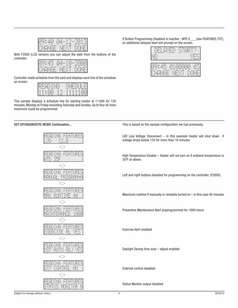
With F2000 (LCD version) you can adjust the date from the buttons of the controller.
Controller reads schedule from the card and displays each line of the schedule on screen:
This sample displays a schedule line for starting heater at 11:00h for 120 minutes, Monday to Friday excluding Saturday and Sunday. Up to four (4) lines maximum could be programmed.
SET-UP/DIAGNOSTIC MODE Continuation...
If Button Programming Disabled is inactive : BPD 0___ (see FEATURES.TXT), an additional delayed start will prompt on the screen.
This is based on the sample configuration we had previously.
LVD Low Voltage Disconnect – in this example heater will shut down if voltage drops below 12V for more than 10 minutes.
High Temperature Disable – Heater will not turn on if ambient temperature is 35ºF or above.
Left and right buttons disabled for programming on the controller. (F2000)
Maximum runtime if manually or remotely turned on – in this case 40 minutes
Preventive Maintenance Alert preprogrammed for 1000 hours
Exercise Alert enabled
Daylight Saving time auto – adjust enabled
External control disabled
Status Monitor output disabled
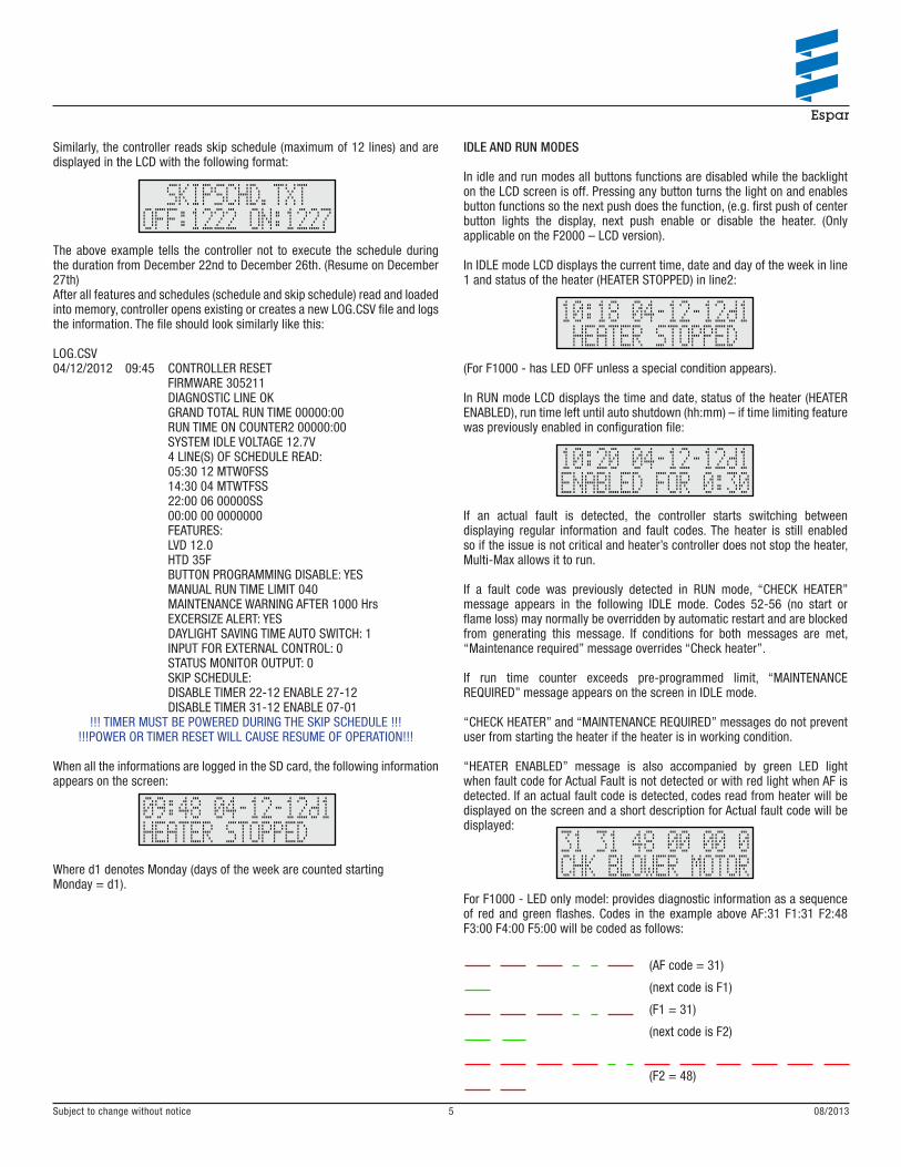
Similarly, the controller reads skip schedule (maximum of 12 lines) and are displayed in the LCD with the following format:
The above example tells the controller not to execute the schedule during the duration from December 22nd to December 26th. (Resume on December 27th)After all features and schedules (schedule and skip schedule) read and loaded into memory, controller opens existing or creates a new LOG.CSV file and logs the information. The file should look similarly like this:
LOG.CSV04/12/2012 09:45 CONTROLLER RESET FIRMWARE 305211 DIAGNOSTIC LINE OK GRAND TOTAL RUN TIME 00000:00 RUN TIME ON COUNTER2 00000:00 SYSTEM IDLE VOLTAGE 12.7V 4 LINE(S) OF SCHEDULE READ: 05:30 12 MTW0FSS 14:30 04 MTWTFSS 22:00 06 00000SS 00:00 00 0000000 FEATURES: LVD 12.0 HTD 35F BUTTON PROGRAMMING DISABLE: YES MANUAL RUN TIME LIMIT 040 MAINTENANCE WARNING AFTER 1000 Hrs EXCERSIZE ALERT: YES DAYLIGHT SAVING TIME AUTO SWITCH: 1 INPUT FOR EXTERNAL CONTROL: 0 STATUS MONITOR OUTPUT: 0 SKIP SCHEDULE: DISABLE TIMER 22-12 ENABLE 27-12 DISABLE TIMER 31-12 ENABLE 07-01
!!! TIMER MUST BE POWERED DURING THE SKIP SCHEDULE !!!!!!POWER OR TIMER RESET WILL CAUSE RESUME OF OPERATION!!!
When all the informations are logged in the SD card, the following information appears on the screen:
Where d1 denotes Monday (days of the week are counted startingMonday = d1).
IDLE AND RUN MODES
In idle and run modes all buttons functions are disabled while the backlight on the LCD screen is off. Pressing any button turns the light on and enables button functions so the next push does the function, (e.g. first push of center button lights the display, next push enable or disable the heater. (Only applicable on the F2000 – LCD version).
In IDLE mode LCD displays the current time, date and day of the week in line 1 and status of the heater (HEATER STOPPED) in line2:
(For F1000 - has LED OFF unless a special condition appears).
In RUN mode LCD displays the time and date, status of the heater (HEATER ENABLED), run time left until auto shutdown (hh:mm) – if time limiting feature was previously enabled in configuration file:
If an actual fault is detected, the controller starts switching between displaying regular information and fault codes. The heater is still enabled so if the issue is not critical and heater’s controller does not stop the heater, Multi-Max allows it to run.
If a fault code was previously detected in RUN mode, “CHECK HEATER” message appears in the following IDLE mode. Codes 52-56 (no start or flame loss) may normally be overridden by automatic restart and are blocked from generating this message. If conditions for both messages are met, “Maintenance required” message overrides “Check heater”.
If run time counter exceeds pre-programmed limit, “MAINTENANCE REQUIRED” message appears on the screen in IDLE mode.
“CHECK HEATER” and “MAINTENANCE REQUIRED” messages do not prevent user from starting the heater if the heater is in working condition.
“HEATER ENABLED” message is also accompanied by green LED light when fault code for Actual Fault is not detected or with red light when AF is detected. If an actual fault code is detected, codes read from heater will be displayed on the screen and a short description for Actual fault code will be displayed:
For F1000 - LED only model: provides diagnostic information as a sequence of red and green flashes. Codes in the example above AF:31 F1:31 F2:48 F3:00 F4:00 F5:00 will be coded as follows:
(AF code = 31)
(next code is F1)
(F1 = 31)
(next code is F2)
(F2 = 48)
Subject to change without notice 08/20135

Since F3 – F5 cells do not have values, the flashing sequence repeats from this point.
When heater is enabled, time counter stops it automatically when the run time in current cycle reaches pre-programmed value.
In RUN mode, controller also the monitors system voltage and stops heater if voltage goes below pre-programmed value and stays below for 10 minutes. After 8 minutes of under voltage condition the red LED comes on and a warning is displayed. After 10 minutes controller stops the heater and displays “LOW VOLTAGE STOP” message which remains on screen until next start. If at some point the voltage rises above the threshold level, LED turns to green but under voltage counter resets only after some probation period equal to previous under voltage time.
Every time when heater stopped, the new value of run hours is recorded into the power independent memory. All events happened during RUN time are logged on SD card (See Manual, Timer and Remote Start).
When initial information logged, the following information appears on the screen:
Where d1 means Monday (days of the week are counted starting Monday = d1).
MANUAL, TIMER AND REMOTE STARTS AND STOPS
Controlled device can be started and stopped manually, by timer or by external signal (3rd party devices such as remotes). Event started by any of the three inputs can be canceled by any of the others. E.g. Heater was started by timer (pre-programmed), stopping it by button causes normal manual stop. Appropriate message will be recorded in the log file and displayed on the screen for the model with LCD screen.
When heater started by button or external signal, pre-programmed manual run time limit will be applied. Event started by timer will use run time pre-programmed for the very event.If a scheduled event happens when heater is already on, the new run time limit will be applied accordingly to the scheduled event.
HTD – High Temperature Disable - may prevent starting heater by timerif pre-programmed maximum starting temperature is exceeded.
All events will be logged on SD card like in the sample below:
4/12/2012 14:30 SCHEDULE LINE 2: 14:30 040 1111111 SKEPT BECAUSE OF AMBIENT TEMPERATURE AIR SENSOR: 20°C 36°F VOLTAGE: 13.5V
5/12/2012 05:30 SCHEDULE LINE 1: 04:30 120 1111011
5/12/2012 05:30 HEATER ENABLED BY TIMER AIR SENSOR: 18°C 32°F VOLTAGE: 12.1V HRS= 000:06
5/12/2012 05:30 CODES IN HEATERS MEMORY: AF:71 F1:48 F2:48 F3:48 F4:48 F5:48
5/12/2012 05:32 HEATER STOPPED MANUALLY AIR SENSOR: 18°C 32°F VOLTAGE: 13.1V HRS= 000:08
LEFT AND RIGHT BUTTONS (Multi-Max F2000)Left and right buttons are designated for manual increase or decrease run time limit in 10 minutes increments. Minimum setting is 10 minutes, maximum – 24 hrs. If no time limit preset in configuration files, pressing left button in RUN mode switches controller to time limit mode (adjustable by right/left buttons) until heater is stopped manually or by timer.
EXTERNAL CONTROL MODEExternal control wire and start/stop button can override each other so if the heater was started by external device it still can be stopped by button and if the heater was started by button it can be stopped by applying and then removing power from the control wire. If stop button override the external control wire and heater started again from the button, “EXTERNAL START” is displayed indicating that the wire is powered by external device.
CARD LESS OPERATION
If Multi-Max was started without the SD card, it goes directly into manual mode. Manual mode has all the defaults that was previously been discussed in this manual, except for the runtime limit of 10 hours.
More on the runtime at the last page of this manual.
If the SD card is inserted into controller when in card less mode, logging data will be resumed using current setting in clock/calendar (which may or may not have a correct date/time set).
Date and time is not displayed on the screen in card less operation mode.
Subject to change without notice 08/20136

DIAGNOSTIC MODEIf the device reset or powered with middle button depressed (Press RESET, press and hold the middle or the only button, release RESET and keep holding the middle button until LED comes on and stay solid RED) it enters diagnostic mode. After entering this mode, version of the firmware is displayed, and then controller tests diagnostic line for short circuit to positive wire and displays diagnostic value and message “DIAG line OK” or “CHECK DIAG line!” If diagnostic line is not OK, diagnostic feature is disabled.
The controller powers control wire of the heater and tries to activate diagnostic, then displays codes read from heater’s memory.If the codes are read, they are listed in the first line of the screen:
At least Actual fault and F1-F4 will be displayed. If the AF is equal to 0, then 0, F1…F5 are displayed. Fault codes are displayed, (device without LCD displays codes by LED flashes) then a prompt for erasing codes appears. In case if erase option selected, the codes will be attempted to erase and diagnostic menu appears again, so the codes may be read again or diagnostic skipped.
WARNING CODESProduced by series of green/red flashes
1 GREEN Card activated2 RED Diagnostic Line not ok3 RED Wrong date. Provide correct file for setting date/time or restart in card less mode (remove card and reset)4 GREEN No date file found, use existing date5 GREEN Manual mode
2 SHORT YELLOW Exercise heater2 SHORT RED Maintenance required
SELF TEST MODE
If all three buttons are depressed during RESET (for F2000 version), the controller proceeds into TEST mode.
Subject to change without notice 08/20137

Subject to change without notice 08/20138
SECTION A-A
( 44 mm )(1.73”)
( 16 mm )(0.63”)
Ø 9.5 mm (3/8”) FIXINGFOR CABLE ENTRY HOLE
2 x Ø 7.5 mm (1/4”) FIXING S FORESPAR CONTROLLER LUGS
( 65.5 mm )(2.58”)
20 mm(0.79”)
57.66 mm(2.27”)