multi-link structured wiring catalog - steven...
TRANSCRIPT

SQUARE D Multi-Link Structured Wiring System
Class 1400
Schneider Electric Brands


Table of Contents
04/03
Introduction . . . . . . . . . . . . . . . . . . . . . . . . . . . . . . . . . . . . . . . . . . . . . . . . . . . . . . . 5
Product Description . . . . . . . . . . . . . . . . . . . . . . . . . . . . . . . . . . . . . . . . . . . . . . . . . . . . 5
Application Data . . . . . . . . . . . . . . . . . . . . . . . . . . . . . . . . . . . . . . . . . . . . . . . . . . . . . . . 5
Wiring Guide . . . . . . . . . . . . . . . . . . . . . . . . . . . . . . . . . . . . . . . . . . . . . . . . . . . . . . 7
Recommended Pre-wire Schemes . . . . . . . . . . . . . . . . . . . . . . . . . . . . . . . . . . . . . . . . . 7
Installing and Terminating the Cable . . . . . . . . . . . . . . . . . . . . . . . . . . . . . . . . . . . . . . . 8
Recommended Product Configurations . . . . . . . . . . . . . . . . . . . . . . . . . . . . . . . . . . . . 11
Enclosures and Brackets . . . . . . . . . . . . . . . . . . . . . . . . . . . . . . . . . . . . . . . . . . . 19
Product Description . . . . . . . . . . . . . . . . . . . . . . . . . . . . . . . . . . . . . . . . . . . . . . . . . . . 19
General Information and Application Data . . . . . . . . . . . . . . . . . . . . . . . . . . . . . . . . . . 22
Television/Telephone Combination Hubs . . . . . . . . . . . . . . . . . . . . . . . . . . . . . . . 25
Product Description . . . . . . . . . . . . . . . . . . . . . . . . . . . . . . . . . . . . . . . . . . . . . . . . . . . 25
General Information and Application Data . . . . . . . . . . . . . . . . . . . . . . . . . . . . . . . . . . 25
Specifications . . . . . . . . . . . . . . . . . . . . . . . . . . . . . . . . . . . . . . . . . . . . . . . . . . . . . . . . 26
Voice and Data Network Hubs . . . . . . . . . . . . . . . . . . . . . . . . . . . . . . . . . . . . . . . 27
Product Description . . . . . . . . . . . . . . . . . . . . . . . . . . . . . . . . . . . . . . . . . . . . . . . . . . . 27
Specifications . . . . . . . . . . . . . . . . . . . . . . . . . . . . . . . . . . . . . . . . . . . . . . . . . . . . . . . . 30
Expanding the Network . . . . . . . . . . . . . . . . . . . . . . . . . . . . . . . . . . . . . . . . . . . . . . . . 30
Audio Distribution Hub . . . . . . . . . . . . . . . . . . . . . . . . . . . . . . . . . . . . . . . . . . . . . 31
Product Description . . . . . . . . . . . . . . . . . . . . . . . . . . . . . . . . . . . . . . . . . . . . . . . . . . . 31
Video Distribution Hubs . . . . . . . . . . . . . . . . . . . . . . . . . . . . . . . . . . . . . . . . . . . . 33
Product Description . . . . . . . . . . . . . . . . . . . . . . . . . . . . . . . . . . . . . . . . . . . . . . . . . . . 33
General Information and Application Data . . . . . . . . . . . . . . . . . . . . . . . . . . . . . . . . . . 38
Specifications . . . . . . . . . . . . . . . . . . . . . . . . . . . . . . . . . . . . . . . . . . . . . . . . . . . . . . . . 38
Satellite Multi-Switch . . . . . . . . . . . . . . . . . . . . . . . . . . . . . . . . . . . . . . . . . . . . . . 41
Product Description . . . . . . . . . . . . . . . . . . . . . . . . . . . . . . . . . . . . . . . . . . . . . . . . . . . 41
General Information and Application Data . . . . . . . . . . . . . . . . . . . . . . . . . . . . . . . . . . 41
Modulators . . . . . . . . . . . . . . . . . . . . . . . . . . . . . . . . . . . . . . . . . . . . . . . . . . . . . . 45
Product Description . . . . . . . . . . . . . . . . . . . . . . . . . . . . . . . . . . . . . . . . . . . . . . . . . . . 45
General Information and Application Data . . . . . . . . . . . . . . . . . . . . . . . . . . . . . . . . . . 49
Technical Information . . . . . . . . . . . . . . . . . . . . . . . . . . . . . . . . . . . . . . . . . . . . . . . . . . 50
Specifications . . . . . . . . . . . . . . . . . . . . . . . . . . . . . . . . . . . . . . . . . . . . . . . . . . . . . . . . 52
Video Cameras . . . . . . . . . . . . . . . . . . . . . . . . . . . . . . . . . . . . . . . . . . . . . . . . . . . 55
Product Description . . . . . . . . . . . . . . . . . . . . . . . . . . . . . . . . . . . . . . . . . . . . . . . . . . . 55
General Information and Application Data . . . . . . . . . . . . . . . . . . . . . . . . . . . . . . . . . . 56
Technical Information . . . . . . . . . . . . . . . . . . . . . . . . . . . . . . . . . . . . . . . . . . . . . . . . . . 59
Specifications . . . . . . . . . . . . . . . . . . . . . . . . . . . . . . . . . . . . . . . . . . . . . . . . . . . . . . . . 59
3© 2001–2003 Schneider Electric All Rights Reserved

Table of Contents
4
Video Wall Plate . . . . . . . . . . . . . . . . . . . . . . . . . . . . . . . . . . . . . . . . . . . . . . . . . . 61
Product Description . . . . . . . . . . . . . . . . . . . . . . . . . . . . . . . . . . . . . . . . . . . . . . . . . . . 61
General Information and Application Data . . . . . . . . . . . . . . . . . . . . . . . . . . . . . . . . . . 61
IR Target and Emitter . . . . . . . . . . . . . . . . . . . . . . . . . . . . . . . . . . . . . . . . . . . . . . 63
Product Description . . . . . . . . . . . . . . . . . . . . . . . . . . . . . . . . . . . . . . . . . . . . . . . . . . . 63
General Information and Application Data . . . . . . . . . . . . . . . . . . . . . . . . . . . . . . . . . . 63
Accessories . . . . . . . . . . . . . . . . . . . . . . . . . . . . . . . . . . . . . . . . . . . . . . . . . . . . . 65
Product Description . . . . . . . . . . . . . . . . . . . . . . . . . . . . . . . . . . . . . . . . . . . . . . . . . . . 65
Troubleshooting . . . . . . . . . . . . . . . . . . . . . . . . . . . . . . . . . . . . . . . . . . . . . . . . . . 69
General Troubleshooting Techniques . . . . . . . . . . . . . . . . . . . . . . . . . . . . . . . . . . . . . 69
Radio Frequency Troubleshooting Techniques . . . . . . . . . . . . . . . . . . . . . . . . . . . . . . 69
Modulator Troubleshooting for Cameras . . . . . . . . . . . . . . . . . . . . . . . . . . . . . . . . . . . 70
Glossary . . . . . . . . . . . . . . . . . . . . . . . . . . . . . . . . . . . . . . . . . . . . . . . . . . . . . . . . 71
Structured Wiring Terms . . . . . . . . . . . . . . . . . . . . . . . . . . . . . . . . . . . . . . . . . . . . . . . 71
Index . . . . . . . . . . . . . . . . . . . . . . . . . . . . . . . . . . . . . . . . . . . . . . . . . . . . . . . . . . . 75
Model Number Index . . . . . . . . . . . . . . . . . . . . . . . . . . . . . . . . . . . . . . . . . . . . . . 79
© 2001–2003 Schneider Electric All Rights Reserved 04/03

www.squared.com/multilink IntroductionProduct Description
04/03
Sec
tio
n 1
–In
tro
du
ctio
n
INTRODUCTION
Aluminum Foil Shielding Foam Polyethylene Dielectric Core
PVC Jacket 60% AluminumBraid
Copper Clad Center Conductor
F-Connector
RG-6 Quad
5
PRODUCT DESCRIPTION
The Square D Multi-Link Structured Wiring System represents the next generation of products for home networks. The Square D Multi-Link Structured Wiring System offers a complete range of products that integrate voice, data, and video applications for a complete system solution.
Square D warrants the product to be free from defects in materials and workmanship for eighteen months from the date of invoice from Square D or its authorized sales channel.
The devices are UL® Listed for use in US markets and CUL® Listed for use in Canada.
APPLICATION DATA
The structured wiring modules are wired using Category 5 (CAT-5) or Category 5E (CAT-5E) cable and RG-6 coaxial cables.
All structured wiring modules are easily installed into enclosures, also supplied by Square D.
Category 5 and 5E Cable
Category 5 and 5E cables are made up of four unshielded twisted pairs. Each pair is color coded for application identification. CAT-5 or CAT-5E cables are recommended for telecommunications, camera, and data applications. CAT-5 and CAT-5E cables will support standard analog telephone, digital telephone, and data. Category 5 and Category 5E cables meet TIA/EIA–586A and 570 standards for data applications such as high-speed Internet access. The cables have a bandwidth of 100 MHz and data transmission speeds up to 100 Mbps. CAT-5 and CAT-5E cable installations provide connections for immediate and future computer, video, and telephone upgrades, thus protecting the long-term resale value of the home.
NOTE: Category 5/5E cables should not be routed parallel to the AC power wiring unless 14 in. (356 mm) of separation or greater is provided. Cross Category 5/5E cables over AC power wires at 90°.
RG-6 Coaxial Cable
RG-6 coaxial cable has an 18 gauge copper coated steel center conductor, polyethylene dielectric core, aluminum braid, and PVC jacket. Standard “F” connectors are used for video, audio, and television equipment connections. Under extreme noise conditions, such as near a radio or television transmitter, use quad-shielded RG-6 cable.
NOTES: RG-6 coaxial cable should not be routed parallel to AC power wiring unless 14 in. (356 mm) of separation or greater is provided. Cross RG-6 coaxial cable over AC power wires at 90°.
When bending coaxial cable, a radius of no less than four times the outside diameter of the cable should be maintained. For RG-6 coaxial cable, the bending radius should be 1 - 1 1/2 inches or greater.
© 2001–2003 Schneider Electric All Rights Reserved
Introduction www.squared.com/multilinkApplication Data
6
Sec
tio
n 1
–In
tro
du
ctio
n
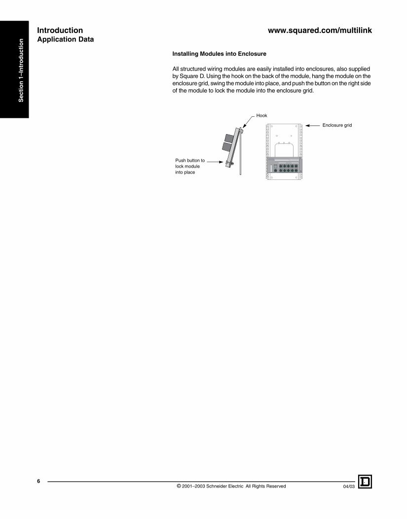
Installing Modules into Enclosure
All structured wiring modules are easily installed into enclosures, also supplied by Square D. Using the hook on the back of the module, hang the module on the enclosure grid, swing the module into place, and push the button on the right side of the module to lock the module into the enclosure grid.
Square D model SDM412PJTelephone Service Hub
RJ-31X
Expansion
RT
RT
RT
RT
4
3
2
1
Telephones
Hook
Push button to lock module into place
Enclosure grid
© 2001–2003 Schneider Electric All Rights Reserved 04/03
www.squared.com/multilink Wiring GuideRecommended Pre-wire Schemes
04/03
Sec
tio
n 2
–Wir
ing
Gu
ideWIRING GUIDE
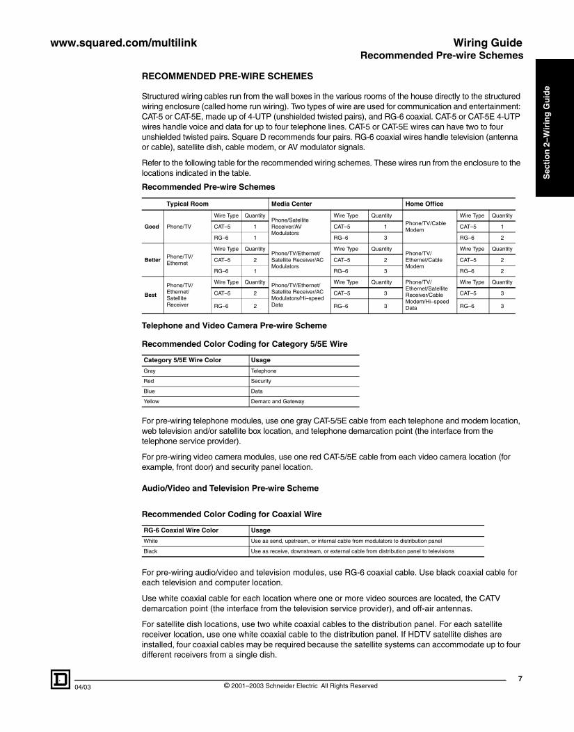
RECOMMENDED PRE-WIRE SCHEMES
Structured wiring cables run from the wall boxes in the various rooms of the house directly to the structured wiring enclosure (called home run wiring). Two types of wire are used for communication and entertainment: CAT-5 or CAT-5E, made up of 4-UTP (unshielded twisted pairs), and RG-6 coaxial. CAT-5 or CAT-5E 4-UTP wires handle voice and data for up to four telephone lines. CAT-5 or CAT-5E wires can have two to four unshielded twisted pairs. Square D recommends four pairs. RG-6 coaxial wires handle television (antenna or cable), satellite dish, cable modem, or AV modulator signals.
Refer to the following table for the recommended wiring schemes. These wires run from the enclosure to the locations indicated in the table.
Telephone and Video Camera Pre-wire Scheme
For pre-wiring telephone modules, use one gray CAT-5/5E cable from each telephone and modem location, web television and/or satellite box location, and telephone demarcation point (the interface from the telephone service provider).
For pre-wiring video camera modules, use one red CAT-5/5E cable from each video camera location (for example, front door) and security panel location.
Audio/Video and Television Pre-wire Scheme
For pre-wiring audio/video and television modules, use RG-6 coaxial cable. Use black coaxial cable for each television and computer location.
Use white coaxial cable for each location where one or more video sources are located, the CATV demarcation point (the interface from the television service provider), and off-air antennas.
For satellite dish locations, use two white coaxial cables to the distribution panel. For each satellite receiver location, use one white coaxial cable to the distribution panel. If HDTV satellite dishes are installed, four coaxial cables may be required because the satellite systems can accommodate up to four different receivers from a single dish.
Recommended Pre-wire Schemes
Typical Room Media Center Home Office
Good Phone/TV
Wire Type QuantityPhone/Satellite Receiver/AV Modulators
Wire Type QuantityPhone/TV/Cable Modem
Wire Type Quantity
CAT–5 1 CAT–5 1 CAT–5 1
RG–6 1 RG–6 3 RG–6 2
BetterPhone/TV/Ethernet
Wire Type QuantityPhone/TV/Ethernet/Satellite Receiver/AC Modulators
Wire Type QuantityPhone/TV/Ethernet/Cable Modem
Wire Type Quantity
CAT–5 2 CAT–5 2 CAT–5 2
RG–6 1 RG–6 3 RG–6 2
Best
Phone/TV/Ethernet/Satellite Receiver
Wire Type QuantityPhone/TV/Ethernet/Satellite Receiver/AC Modulators/Hi–speed Data
Wire Type Quantity Phone/TV/Ethernet/Satellite Receiver/Cable Modem/Hi–speed Data
Wire Type Quantity
CAT–5 2 CAT–5 3 CAT–5 3
RG–6 2 RG–6 3 RG–6 3
Recommended Color Coding for Category 5/5E Wire
Category 5/5E Wire Color Usage
Gray Telephone
Red Security
Blue Data
Yellow Demarc and Gateway
Recommended Color Coding for Coaxial Wire
RG-6 Coaxial Wire Color Usage
White Use as send, upstream, or internal cable from modulators to distribution panel
Black Use as receive, downstream, or external cable from distribution panel to televisions
7© 2001–2003 Schneider Electric All Rights Reserved

Wiring Guide www.squared.com/multilinkInstalling and Terminating the Cable
8
Sec
tio
n 2
–Wir
ing
Gu
ide
Data Pre-wire Scheme
For pre-wiring data modules, use one blue CAT-5/5E cable from each computer location, room with a separate peripheral (such as a laser printer), and room where access to the network is needed.
Wiring a Telephone Wall Plate
To wire a telephone wall plate, refer to the following table.
NOTE: The wiring method shown in the table below requires the use of two-line telephones.
When a fax machine is present or single-line telephones are used, wire line 1 (blue, blue/white pair) to the center pins (marked blue, blue/white) on the RJ-14 jack.
For access to a second line for a fax machine or to enable single-line telephone use, wire line 2 (orange, orange/white pair) to the center pins (marked blue, blue/white) on a second RJ-14 jack.
INSTALLING AND TERMINATING THE CABLE
110 Punch-Down Connectors
The 110 punch-down connector is an insulation displacement connection system typically included on combination telephone/video hubs, telephone hubs, and data hubs.
The CAT-5/5E wires are inserted into the connectors. To push wire into the connector, use only a 110 punch-down tool. When wiring the connector, keep the wire cable sheath close to the connector and do not untwist the wire more than 1/2 in. (13 mm).
Telephone Wall Plate Wiring Using Two Six-Position, Four-Conductor Jacks (RJ-14)
Cable Color Pin Number Connector Color (As Marked on RJ-14 Modular Connector)
Jack 1: Pairs 1 and 2
White/Orange Pin 2 White/Orange
Blue Pin 3 Blue
White/Blue Pin 4 White/Blue
Orange Pin 5 Orange
Jack 2: Pairs 3 and 4
White/Brown Pin 2 White/Orange
Green Pin 3 Blue
White/Green Pin 4 White/Blue
Brown Pin 5 Orange
110 punch-down tool
CAT-5/5E cable
© 2001–2003 Schneider Electric All Rights Reserved 04/03

www.squared.com/multilink Wiring GuideInstalling and Terminating the Cable
04/03
Sec
tio
n 2
–Wir
ing
Gu
ide
Modular Connectors
Modular connectors are attached to each end of a CAT-5/5E jumper cable. Modular connectors are used with television, telephone, data, and Ethernet hubs.
There are three six-position connector types, depending on the number and usage of lines.
Eight-position connectors are used with the telephone expansion hub (model SDM48PX). For residential purposes, it is recommended that the eight-position connectors (RJ-45) are wired to the T568-A wiring standard.
Refer to the table below for the modular connector type and the figures below for wiring configurations.
Modular Connector Types
Line Usage Connector Type
Six-position Connectors
Single-line telephones, answering machines, and modems (six-position, two-conductor) RJ-11
Dual-line telephones and answering machines (six-position, four-conductor) RJ-14
Three-line key service unit (six-position, six-conductor) RJ-25
Eight-position Connectors
Telephones, Ethernet (10 Base-T and 100 Base-T), and data lines (eight-position, eight-conductor) RJ-45
9© 2001–2003 Schneider Electric All Rights Reserved

Wiring Guide www.squared.com/multilinkInstalling and Terminating the Cable
10
Sec
tio
n 2
–Wir
ing
Gu
ide
Wiring a Modular Connector
The illustrations below show the modular connectors positioned with the tabs down, pins up, and the openings facing toward you.
Wiring a Modular Jack
To wire a modular jack with CAT-5/5E wiring, follow the wire color code for the TIA/EIA-568-A wiring standard as illustrated for the RJ-45 modular connector. Position the first pair of wires to the terminals closest to the end of the jack. Do not untwist the pairs more than 1/2 in. (13 mm) from the termination point. Push the wires into the terminals of the jack using a 110 punch-down tool and trim. After all pairs are connected, snap on strain relief caps.
TT RRTR TRRT T T TTTR R RR R1 2 3 4 5 6 7 81 2 3 4 5 6 1 2 3 4 5 6 1 2 3 4 5 6
Pair 1
Pair 2
Pair 1
Pair 2Pair 3 Pair 4
Pair 1
Pair 2
Pair 1
RJ-11 Connector RJ-14 Connector RJ-25 Connector RJ-45 Connector (T568-A standard)
Pair 3
110 punch-down tool Strain relief caps
© 2001–2003 Schneider Electric All Rights Reserved 04/03

www.squared.com/multilink Wiring GuideRecommended Product Configurations
04/03
Sec
tio
n 2
–Wir
ing
Gu
ide
RECOMMENDED PRODUCT CONFIGURATIONS
The following product configurations are guides for installing a structured wiring system for the most common applications.
Basic Home
• Distributes two telephone lines to six locations and one cable input to four locations
• Handles multiple telephone lines for voice, fax and Internet access
Catalog Number DescriptionSDM18BW 18 In. (457.2 mm) Enclosure
SDM18CW 18 In. (457.2 mm) Cover
SDM26P14V Combination Telephone/Video Hub
OUTOUTIN
532-230 5MHzto 1000MHz
OUT ININ OUT ININ OUT ININ OUT ININ
SPLITTER COMBINERCOMBINERR
TelephonesFromTelco
Square D model SDM26P14VCombo Hub (2 lines x 6 phones, 1inpu t x 4 televisions)
RT
2
RT
1
RG-6 coaxial cables connected to four television wall plates
Internal telephone cables connected to six telephone wall plates (CAT–5/5E unshielded twisted pairs). Each cable can have two to four pairs of wire.
Incomingtelephone service (two lines)
Incoming RG-6 coaxial cable from cable company or local antenna
CAT-5/5E cable
SDM26P14V
11© 2001–2003 Schneider Electric All Rights Reserved

Wiring Guide www.squared.com/multilinkRecommended Product Configurations
12
Sec
tio
n 2
–Wir
ing
Gu
ide
Incoming telephservice (four line
Incoming Rcable from cor local ante
Basic Home Office
• Distributes four telephone lines to six locations and one cable input to four locations
• Allows sharing of files and peripherals among two computers
• Handles multiple telephone lines for voice, fax, and Internet access
Up to eight data jacks can be wired using this equipment. However, unless an Ethernet hub is used, only two computers can be networked by connecting two RJ-45 jacks with a patch cord on the data hub.
NOTE: To allow two computers to be networked, one crossover patch cord must be used somewhere in the system, i.e., between one computer and data outlet.
Catalog Number DescriptionSDM18BW 18 In. (457.2 mm) Enclosure
SDM18CW 18 In. (457.2 mm) Cover
SDM8D Eight-Port Data Hub
SDM46P14V Combination Telephone/Video Hub
OUTOUTIN
532-230 5MHzto 1000MHz
OUT ININ OUT ININ OUT ININ OUT ININ
COMBINERCOMBINERR
TelephonesFrom Telco
Square D model SDM46P14VCombo Hub (2 lines x 6 phones, 1 inpu t x 4 televisions)
RT
2
RT
1
RT
RT
3
4
R
RT
RT
Square D model SDM8DData Hub ( 8 cables, TIA-568A) Category 5 Compliant
RG-6 coaxial cables connected to four television wall plates
one s)
G-6 coaxial able company nna
Cables connecting to data jacks in eight wall plates
Internal telephone cables connected to six telephone wall plates (CAT-5/5E unshielded twisted pairs). Each cable can have two to four pairs of wire.
CAT-5/5E cable
SDM46P14V
SDM8D
CAT-5/5E cable
© 2001–2003 Schneider Electric All Rights Reserved 04/03

www.squared.com/multilink Wiring GuideRecommended Product Configurations
04/03
Sec
tio
n 2
–Wir
ing
Gu
ide
Incoming telepservice (four lin
Incoming RG-6 coaxiacable company or loca
If high-speed Internet service will be brought to the home over the telephone lines (DSL), the incoming telephone line should be connected to the combination hub (model SDM46P14V) and then jumped to the data hub (model SDM8D) as shown in the figure below. In this scenario, one computer can have DSL service. The high-speed Internet line can easily be moved to another computer by changing the location of the jumper on the SDM8D.
RT
2
RT
1
RT
RT
3
4
OUTOUTIN
532-230 5MHzto 1000MHz
OUT ININ OUT ININ OUT ININ OUT ININ
SPLITTER COMBINERCOMBINERR
TelephonesFrom Telco
Combo Hub (2 lines x 6 phones, 1inpu t x 4 televisions)
Square D model SDM8DData Hub ( 8 cables, TIA-568A) Category 5 Compliant
DSL Modem
Square D model SDM46P14V
R
RT
R
RG-6 coaxial cables connected to four television wall plates
hone es)
l cable from l antenna
Internal telephone cables connected to five telephone wall plates (CAT-5/5E unshielded twisted pairs). Each cable can have two to four pairs of wire.
SDM8D
Cables connecting to data jacks in six wall plates
To data jack in home office
SDM46P14V
Sends DSL to office
13© 2001–2003 Schneider Electric All Rights Reserved
Wiring Guide www.squared.com/multilinkRecommended Product Configurations
14
Sec
tio
n 2
–Wir
ing
Gu
ide
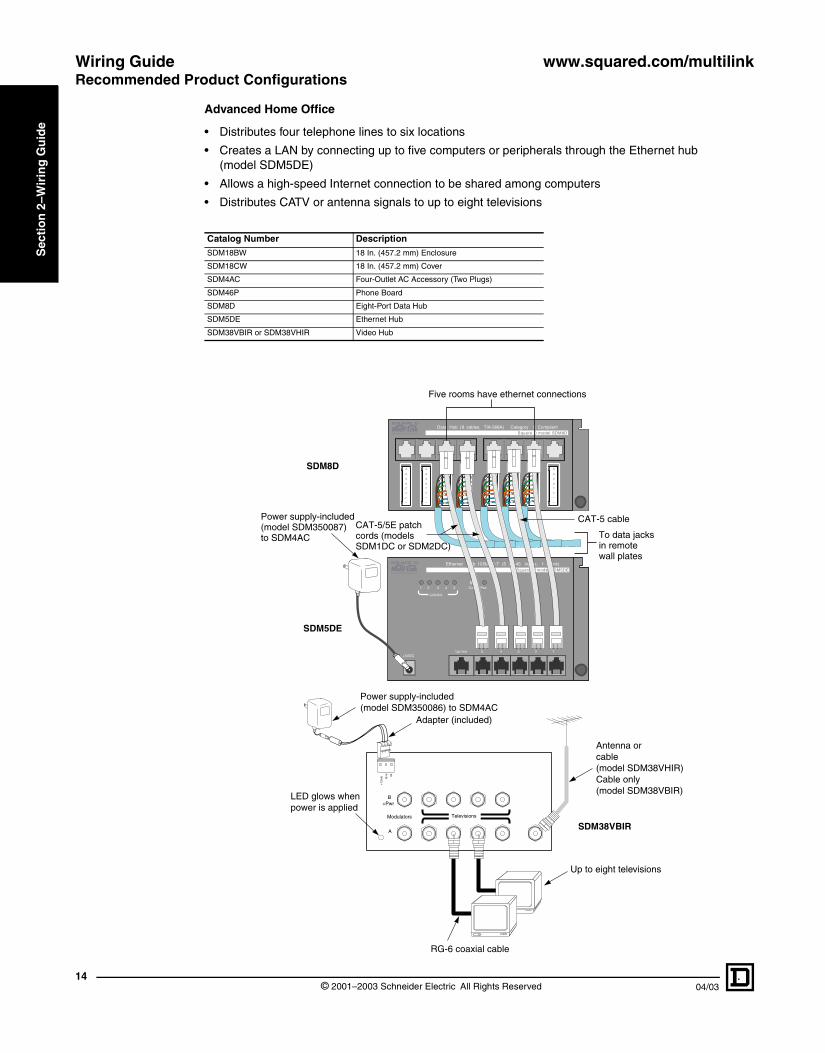
Advanced Home Office
• Distributes four telephone lines to six locations
• Creates a LAN by connecting up to five computers or peripherals through the Ethernet hub (model SDM5DE)
• Allows a high-speed Internet connection to be shared among computers
• Distributes CATV or antenna signals to up to eight televisions
Catalog Number DescriptionSDM18BW 18 In. (457.2 mm) Enclosure
SDM18CW 18 In. (457.2 mm) Cover
SDM4AC Four-Outlet AC Accessory (Two Plugs)
SDM46P Phone Board
SDM8D Eight-Port Data Hub
SDM5DE Ethernet Hub
SDM38VBIR or SDM38VHIR Video Hub
Ethernet Hub BASE-T (5 RJ-45 inputs, 1 uplink)10
Link/Act.
1 2 3 4 5 Col. Pwr
Uplink 5 4 3 2 1+5VDC
Data Hub ( 8 cables, TIA-568A) Category 5 CompliantSquare D model SDM8D
Square D model SDM5DE
Five rooms have ethernet connections
To data jacksin remotewall plates
Power supply-included(model SDM350087)to SDM4AC
CAT-5 cableCAT-5/5E patch cords (models SDM1DC or SDM2DC)
SDM8D
SDM5DE
Televisions
+12
vdc
Gnd IR
Modulators
A
B+Pwr
Power supply-included(model SDM350086) to SDM4AC
RG-6 coaxial cable
Up to eight televisions
LED glows whenpower is applied
Adapter (included)
Antenna orcable(model SDM38VHIR)Cable only(model SDM38VBIR)
SDM38VBIR
© 2001–2003 Schneider Electric All Rights Reserved 04/03

www.squared.com/multilink Wiring GuideRecommended Product Configurations
04/03
Sec
tio
n 2
–Wir
ing
Gu
ide
NOTES: If high-speed Internet service is brought to the home over the telephone lines (DSL), the incoming telephone line should be connected to the SDM46P and then jumped to the SDM8D through the DSL modem (as shown in the figure below).
If the Internet service provider (ISP) allows multiple IP addresses to be leased to one modem, then the high-speed Internet service may be available to all the computers in the home using the Multi-Link Ethernet Hub. In this situation, the high-speed Internet line will jump from the SDM8D to the “uplink” port in the SDM5DE. All the computers connected to the Ethernet hub must have firewall software or hardware installed since they all will have access to the high-speed line at the same time.
If the ISP does not allow multiple IP addresses to be leased to one modem, then replace the Multi-Link Ethernet Hub in the figure below with a router (purchased separately).
Ethernet Hub BASE-T (5 RJ-45 inputs, 1 uplink)10
Link/Act.
1 2 3 4 5 Col. Pwr
Uplink 5 4 3 2 1+5VDC
Data Hub ( 8 cables, TIA-568A) Category 5 CompliantSquare D model SDM8D
Square D model SDM5DE
Five rooms have ethernet connections
To data jacksin remotewall plates
Power supply-included(model SDM350087)to SDM4AC
CAT-5 cable
Square D model SDM46PTelephone Master Hub (4 lines x 6 phones)
TelephonesFromTelco
RJ31X
Out
ExpansionPorts
RT
4
RT
3
RT
2
RT
1
DSL Modem
SDM8D
SDM5DE
SDM46P
Security system connection (RJ-31X only)
Four lines from telephone company (CAT-5/5E, four unshielded twisted pairs)
15© 2001–2003 Schneider Electric All Rights Reserved

Wiring Guide www.squared.com/multilinkRecommended Product Configurations
16
Sec
tio
n 2
–Wir
ing
Gu
ide
Advanced Video and Security Camera
• Distributes four telephone lines to six locations
• Creates a local channel for viewing a camera signal
• Distributes camera signal along with the cable television or antenna signals to up to eight televisions
• No power is necessary at the camera, it is powered through the channel injector
• Multiple cameras can be added to the system (a channel injector is needed for each one)
Catalog Number DescriptionSDM18BW 18 In. (457.2 mm) Enclosure
SDM18CW 18 In. (457.2 mm) Cover
SDM4AC Four-Outlet AC Accessory (Two Plugs)
SDM46P Phone Board
SDM38VBIR Video Hub
SDM1VC Black and White Camera
SDM11VMB or SDM11VMH Channel Injector
Make all cables and CAT-5 connections first. Power the channel injector last.
Connect antenna or incoming cable to channel injector (model SDM11VMH) CATV/Ant input or the CATV to model SDM11VMB.
RG-6 coaxial cableCAT-5/5E cable
Video camera-rear view(model SDM1VC)
Power supply-included(model SDM350079) to model SDM4AC
Televisions
+12
vdc
Gnd IR
Modulators
A
B+Pwr
Power supply-included(model SDM350086) to SDM4AC
RG-6 coaxial cable
Up to eight televisions
LED glows whenpower is applied
Adapter (included)
SDM11VMBor
SDM11VMH
SDM1VC
SDM38VBIR
© 2001–2003 Schneider Electric All Rights Reserved 04/03

www.squared.com/multilink Wiring GuideRecommended Product Configurations
04/03
Sec
tio
n 2
–Wir
ing
Gu
ide
Media Center and Security Camera
• Distributes four telephone lines to six locations
• Creates a local channel for viewing a camera signal• Distributes camera signal along with the cable television or antenna signals to up to eight televisions• No power is necessary at the camera, it is powered through the channel injector
• Multiple cameras can be added to the system (channel injectors can be cascaded)• Video sources, such as DVD players, are connected via line level inputs to the set top modulator
(model SDM41VTST)• Set top modulator modulates all the inputs and combines them onto a single coaxial cable for distribution
back to the video hub• Output of the set top modulator is connected to port B of the video hub, which allows the video hub to be
powered via the set top modulatorNOTE: Port A on the video hub is also used to connect modulated signals, however, no IR control can be passed through this port
• Cable or antenna signal is connected to the model SDM11VMB• IR targets are connected in-line with each television where IR control is desired
• IR emitters are connected to the set top modulator and position over the IR sensor on the video source device
For satellite applications, see pages 41–43.
Catalog Number Description
SDM18BW 18 In. (457.2 mm) Enclosure
SDM18CW 18 In. (457.2 mm) Cover
SDM4AC Four-Outlet AC Accessory (Two Plugs)
SDM46P Phone Board
SDM38VBIR or SDM38VHIR Video Hub
SDM41VTST 4-Input Set Top Modulator
SDM2VCC Color Camera
SDM11VMB or SDM11VMH Channel Injector
SDM1VIR IR Target
SDM2VIR IR Emitter
17© 2001–2003 Schneider Electric All Rights Reserved

Wiring Guide www.squared.com/multilinkRecommended Product Configurations
18
Sec
tio
n 2
–Wir
ing
Gu
ide
CAT-5/5E cable
Use only shielded75 ohm coaxialcable
Video/audio outputs
VCR
Power option-Do not poweris obtained through port Bof set top modulator.
Power connection
SDM41VT
SDM38VHIR or SDM38VBIR
SDM11VMBor
SDM11VMH
CA DBC
HC
CH
D
VIDEO AUDIOL AUDIOR
CH
AC
HB
VIDEO AUDIOL AUDIOR
OUTPUT
900mA15VDCPOWER
VCR
12:0012:00
Remove jumper for Hi-Z(See manual)
A BC D
Make all cables and CAT-5 connections first. Power the channel injector last.
Connect antenna or incoming cable to channel injector (model SDM11VMH) CATV/Ant input or the CATV to model SDM11VMB.
Video camera-rear view
Power supply-included(model SDM350079) to model SDM4AC
Satellite dish and receiver
Video/audio outputs
CCTV Camera at front door
Optional IR emitter (model SDM2VIR) repeats what theIR target “sees” in the other room.
Control the DVD,DSS, or VCRfrom any room.
Attach the IR emitterdirectly over the IR sensor.
To more televisions
Terminating jumpers(on side of unit)
RCA "Y" adapter to local monitor or DolbyPro-Logic system
DVD
RG-6 coaxial preferred
. Power
Optional IR target (model SDM1VIR) may be used at any or all televison locations.
Note: The satellite dish and receiver, CCTV Camera, VCR, and DVD shown are not Square DMulti-Link products.
RG-6 coaxial cable
SDM46P
Square D model SDM46PTelephone Master Hub (4 lines x 6 phones)
TelephonesFromTelco
RJ31X
Out
ExpansionPorts
RT
4
RT
3
RT
2
RT
1SDM1VC
Security system connection (RJ-31X only)
Four lines from telephone company (CAT-5/5E, four unshielded twisted pairs)
Internal telephone cable connected to six telephone wall plates (CAT-5/5E unshielded twisted pairs). Each cable can have two to four pairs of wire.
© 2001–2003 Schneider Electric All Rights Reserved 04/03

www.squared.com/multilink Enclosures and BracketsProduct Description
04/03
Sec
tio
n 3
–En
clo
sure
s an
d
Bra
cket
s
ENCLOSURES AND BRACKETS
PRODUCT DESCRIPTION
The enclosures are the housing components of the Square D Multi-Link Structured Wiring System. Each enclosure has a mounting grid, allowing any structured wiring module to easily mount into the enclosure. Modules can be mounted on either side of the grid and upside down.
The universal mounting bracket (model SDM10BW) can be surface mounted over a single- or double-gang box or mud ring. Any Square D Multi-Link Structured Wiring module can be installed onto the mounting bracket. To give the bracket a finished look, a snap-on cover (model SDM10CW) is available.
Universal Mounting Bracket (Model SDM10BW)
Features:
• 10 in. (254 mm) high, 6.5 in. (165 mm) wide, .35 in. (9 mm) deep
• 10 in. (254 mm) of grid mounting space
• Vertical or horizontal mounting
• Surface mount over single- or double-gang openings
• Optional cover (model SDM10CW)
• Painted steel, white
Cover (Model SDM10CW)
Features:
• 11 in. (279 mm) high, 6.7 in. (170 mm) wide, 4.5 in. (114 mm) deep
• Snap-on cover design
• Painted steel, white
SDM10BW SDM10BW With Modules Installed
19© 2001–2003 Schneider Electric All Rights Reserved

Enclosures and Brackets www.squared.com/multilinkProduct Description
© 220
Sec
tio
n 3
–En
clo
sure
s an
d
Bra
cket
s
SDM18BW With Modules Installed
SDM18CW and SDM18BW
Enclosures (Models SDM18BW and SDM36BW)
Features:
• Model SDM18BW is 18 in. (457.2 mm) high, 14.25 in. (362 mm) wide, and 3.5 in. (89 mm) deep, with 34 in. (864 mm) of grid mounting space
• Model SDM18BW has two columns of grid mounting space, each column is 17 in. (432 mm)
• Model SDM36BW is 36 in. (914.4 mm) high, 14.25 in. (362 mm) wide, and 3.5 in. (89 mm) deep, with 70 in. (1778 mm) of grid mounting space
• Model SDM36BW has two columns of grid mounting space, each column is 35 in. (889 mm)
• Side mounting tabs included for field installation
• Fits between studs on 16 in. (406 mm) center lines
• Surface or flush mounting
• Optional combination flush/surface cover: cover dimensions for SDM18CW –19.5 in. (495.3 mm) high, 15.75 in. (400 mm) wide and SDM36CW–37.5 in. high (953 mm), 15.75 (400 mm) wide
• Can be mounted upside down
• Accepts model SDM4AC or model SDM8AC power accessory
• Four 2 in. (51 mm) and two 1/2 in. (13 mm) knockouts in each endwall
• Painted steel, white
• Paint shield included
001–2003 Schneider Electric All Rights Reserved 04/03

www.squared.com/multilink Enclosures and BracketsProduct Description
04/03 © 2
Sec
tio
n 3
–En
clo
sure
s an
d
Bra
cket
s
SDM8AC
SDM4AC
AC Power Accessories (Models SDM8AC and SDM4AC)
The AC power accessories (models SDM8AC and SDM4AC) mount inside the enclosures to provide a UL® listed location for power supplies. All of the enclosures accept the AC power accessories.
Features:
• SDM8AC will mount four receptacles, providing eight outlets for four power supplies
• SDM4AC will mount two receptacles, providing four outlets for two power supplies
• Uses standard duplex receptacles, not included
• Mounts in any of the four corners of model SDM18BW or model SDM36BW enclosure
• Mounting hardware included
• UL Listed
• SDM8AC covers 5.5 in. (140 mm) of grid mounting space on each side, 11 in. (280 mm) total
• SDM4AC covers 5.5 in. (140 mm) of grid mounting space on one side
SDM18BW with SDM4AC and Other Modules Installed
21001–2003 Schneider Electric All Rights Reserved

Enclosures and Brackets www.squared.com/multilinkGeneral Information and Application Data
22
Sec
tio
n 3
–En
clo
sure
s an
d
Bra
cket
s
GENERAL INFORMATION AND APPLICATION DATA
Mounting the Enclosure
The enclosures can be flush mounted between studs. For versatile flush mounting, the mounting tabs are field installed. Three available positions for the flush mounting tabs allow for wall thicknesses of 1/2 in. (13 mm), 5/8 in. (16 mm) or 3/4 in. (19 mm).
Nail holes are provided in each sidewall for flush mounting in existing installations. Mounting holes are also provided in the rear of the enclosure for surface mounting.
Covers SDM18CW and SDM36CW are combination covers for flush or surface applications.
NOTE: The enclosure should not be mounted next to an AC power distribution panel. Maintain 17.5 in. (445 mm) or more between the structured wiring panel and the home’s AC panel.
Mounting the AC Power Accessory
The AC power accessory is easily mounted into the enclosure using the hardware provided. The AC power accessory can be mounted into any corner of the enclosure.
Low voltage wires exit the AC power accessory through the grommets provided. The grommets can be cut to accommodate the wiring.
16.00 in. on center (406 mm)
Knockout
Enclosure
Mounting tab holeand hole inside enclosure
OEMAC ADAPTOR
Part no.: 123-456
UL
Location of knockouts for 120 VAC
Grommet cut for wiring
AC Power Accessory Mounting Locations (SDM8AC depicted)
Top or bottomEnclosure
Left or right
© 2001–2003 Schneider Electric All Rights Reserved 04/03

www.squared.com/multilink Enclosures and Brackets
04/03
Sec
tio
n 3
–En
clo
sure
s an
d
Bra
cket
s
General Information and Application DataGrounding Lug
The AC power accessories include a grounding lug. The enclosures do not include a separate grounding lug. However, there is a #10–32 threaded hole provided in the top and bottom endwall for the user to install ground lugs, as necessary.
Installing the Cables
Install the data and video cables into the enclosure through removable knockouts. Line the knockout holes with grommets (provided) to protect incoming cable.
Installing the Cover
Cover installation is streamlined with temporary hardware (provided).
Grommet
Cabling running throughknockout hole
Knockout hole withgrommet
Cabling in enclosure
Paint shield
Install nails through the mounting holesto temporarily align screw holes.
Cover
Enclosure mounting holes
23© 2001–2003 Schneider Electric All Rights Reserved

Enclosures and Brackets www.squared.com/multilinkGeneral Information and Application Data
© 224
Sec
tio
n 3
–En
clo
sure
s an
d
Bra
cket
s
001–2003 Schneider Electric All Rights Reserved 04/03

www.squared.com/multilink Television/Telephone Combination Hubs
04/03
Sec
tion
4–T
elev
isio
n/T
elep
hon
e C
om
bin
atio
n H
ubs
TELEVISION/TELEPHONE COMBINATION HUBS
Product DescriptionPRODUCT DESCRIPTION
The combination hubs provide a four-way passive splitter to distribute incoming video (CATV or antenna) signals to four locations. The hubs incorporate 110 punch-down blocks for distributing telephone lines.
Combination Hubs (Models SDM26P14V and SDM46P14V)
Features:
• Distributes CATV or antenna to four locations
• Telephone service for two lines (model SDM26P14V) or four lines (SDM46P14V) with outputs to six locations
• 3 in. (76.2 mm) of grid mounting space.Video F-connectors extend 1/2 in. (13 mm) above the hub mounting pan. Allow approximately 2 in. (51 mm) clearance for cable bending radius above the module.
GENERAL INFORMATION AND APPLICATION DATA
Combination Hubs
See the following figure for the typical installation of combination hubs.
SDM26P14V SDM46P14V
OUTOUTIN
532-230 5MHzto 1000MHz
OUT ININ OUT ININ OUT ININ OUT ININ
SPLITTER COMBINERCOMBINERR
TelephonesFromTelco
Square D model SDM26P14VCombo Hub (2 lines x 6 phones, 1inpu t x 4 televisions)
RT
2
RT
1
RG-6 coaxial cables connected to four television wall plates
RG-6 coaxial cable from cable company or antenna
Two lines from telephone company (CAT-5/5E unshielded twisted pairs)
Internal telephone cables connected to six telephone wall plates (CAT-5/5E, two unshielded twisted pairs). Each cable can have two to four pairs of wire. SDM26P14V
25© 2001–2003 Schneider Electric All Rights Reserved

Television/Telephone Combination Hubs www.squared.com/multilinkGeneral Information and Application Data
26
Sec
tion
4–T
elev
isio
n/T
elep
ho
ne
Co
mb
inat
ion
Hu
bs
SPECIFICATIONS
Passive Splitter
The specifications for the passive video splitter portion of the combination hubs are shown in the following table.
Parameter Frequency (MHz) SDM26P14VSDM46P14V
Insertion Loss In-Out (dB maximum)
5–40 6.7
40–400 6.9
400–500 7.2
500–600 7.5
600–1000 7.8
Return Loss Input (dB maximum)
5–40 22
40–400 24
400–500 27
500–600 25
600–1000 23
Return Loss Output (dB minimum)
5–40 24
40–400 26
400–500 24
500–600 25
600–1000 23
Isolation OUT-OUT(dB minimum)
5–40 24
40–400 28
400–500 25
500–600 24
600–1000 23
Power Pass 500 mA One port or all ports
Impedance 5–1000 75 ohms
RFI (dB) 5–1000 130 dB
© 2001–2003 Schneider Electric All Rights Reserved 04/03

www.squared.com/multilink Voice and Data Network Hubs
04/03 ©
Sec
tio
n 5
–Vo
ice
and
Dat
a N
etw
ork
Hu
bs
Square D model SDM46PTelephone Master Hub (4 lines x 6 phones)
TelephonesFromTelco
RJ31X
Out
ExpansionPorts
RT
4
RT
3
RT
2
RT
1
110D110D-4-4J8J8
BluBlu
110D110D-4-4J7J7
BluBlu
RJ-45RJ-45J9J9
RJ-45RJ-45J10J10
110D-4110D-4J1J1
110D110D-4-4J2J2
110D110D-4-4J3J3
110D110D-4-4J4J4
110D110D-4-4J5J5
110D110D-4-4J6J6
BluBluBluBluBluBluBluBluBluBluBluBlu
TelephonesExpansionPorts
In
Out
Square D model SDM48PXTelephone Expansion Hub (4 lines x 8 phones)
RT
RT
RT
RT
4
3
2
1
110D110D-4-4J8J8
BluBlu
110D110D-4-4J7J7
BluBlu
RJ-45RJ-45J9J9
RJ-45RJ-45J10J10
110D110D-4-4J1J1
110D110D-4-4J2J2
110D110D-4-4J3J3
110D110D-4-4J4J4
110D110D-4-4J5J5
110D110D-4-4J6J6
BluBluBluBluBluBluBluBluBluBluBluBlu
TelephonesExpansionPorts
In
Out
Square D model SDM48PXTelephone Expansion Hub (4 lines x 8 phones)
RT
RT
RT
RT
4
3
2
1
Telephone Master Hub(model SDM46P)
Telephone Expansion Hub(model SDM48PX)
Telephone Expansion Hub(model SDM48PX)
Security system connection (RJ–31X only)
Four lines from telephone company (CAT–5/5E, four unshielded twisted pairs)
CAT–5 patch cord
CAT–5 patch cord
SDM46P
SDM48PX
Product DescriptionPRODUCT DESCRIPTION
The voice and data network hubs distribute telephone and data signals to multiple locations throughout the home. Each hub uses the standard grid mounting and will fit in any enclosure model or the universal mounting bracket.
Telephone Master Hub (Model SDM46P)
Features:
• Telephone service for four lines with outputs to six separate locations
• Security panel connection RJ-31X only (top jack) for seizure of line 1
• 110 punch-down connectors
• Can be mounted upside down
• Expansion jack RJ-45 (bottom jack) for telephone expansion hub (model SDM48PX)
• 3 in. (76.2 mm) of grid mounting space
Telephone Expansion Hub (Model SDM48PX)
Features:
• Accessory to telephone master hub (model SDM46P)
• Telephone service for four lines with outputs to eight separate locations (when used with SDM46P, 14 outlets are accommodated)
• CAT-5/5E patch cord included to connect to SDM46P
• 110 punch-down connectors
• Can be mounted upside down
• 3 in. (76.2 mm) of grid mounting space
• Expansion jack allows multiple SDM48PX units to be cascaded, providing expanded telephone distribution (see graphic on the left)
Telephone Interface Hub/Patch Panel (Model SDM412PJ)
Features:
• Telephone service for four lines with outputs to twelve separate locations
• RJ-45 modular jacks
• 110 punch-down connectors for incoming telephone company service
• Can be mounted upside down
• 3 in. (76.2 mm) of grid mounting space
• Expansion jack allows connection to additional SDM412PJ for large applications
• Use with SDM8D data hub and SDM5DE Ethernet hub to allow easy reassignment of phone outlets to data network outlets
SDM412PJ
272001–2003 Schneider Electric All Rights Reserved

Voice and Data Network Hubs www.squared.com/multilinkProduct Description
© 2028
Sec
tio
n 5
–Vo
ice
and
Dat
a N
etw
ork
Hu
bs
SDM8D
SDM8DB
Square D model SDM8DH628Data Hub ( 8 cables, TIA-568A) Category 5 Compliant
Square D model SDM8D Square D model SDM8D
H628( 8 5
(TIA-568A)Category5Compliant
CAT-5/5E data hub(model SDM8D)
CAT-5/5E data hub(model SDM8D)
Cablesconnectingto voice or data jacksin eightwall plates
Telephonecompany line
Data Termination Hub (Model SDM8D)
Features:
• Certified 100 Base-T performance
• CAT-5/5E performance in a multi-port hub
• Terminates eight CAT-5/5E lines with RJ-45 jacks
• Terminates eight CAT-5/5E lines with 110 punch-down connectors
• 110 punch-down connectors are connected to the RJ-45 jacks
• Can be mounted upside down
• Circuits may be bridged for telephone distribution
• 3 in. (76.2 mm) of grid mounting space
• Suitable for Digital Subscriber Line (DSL) from telephone company
• Distributes Ethernet connections
• Distributes camera connections
The data termination hub can be used for telephone distribution by connecting two data hubs using CAT-5/5E patch cords. In the figure to the left, one hub shows the telephone lines bridged at the hub to bring telephone distribution to the jacks. The additional hub has the cables connecting to voice or data jacks in eight wall plates.
Bridgeable CAT-5/5E Hub (Model SDM8DB)
Features:
• Certified 100 Base-T performance
• Eight CAT-5/5E circuits (110 to RJ-45)
• Eight additional 110 connectors to bridge for telephone distribution (see diagram below)
• 4.5 in. (114.3 mm) of grid mounting space
The bridgeable CAT-5/5E data hub can also be used for telephone distribution. In the following figure, three telephone outlets are wired using CAT-5/5E cables terminated to the lower section of 110 punch-down connectors. The wires can also be terminated into the RJ-45 jacks via RJ-45 plugs. To bring telephone distribution to the jacks, bridge the telephone lines by running the incoming telephone lines across the top set of 110 punch-down connectors. All CAT-5/5E circuits can be bridged for telephone distribution. The remaining terminals are available for use as data terminations.
Square D model SDM8DB
Data Hub (8 cables, TIA-568A) Category 5 CompliantThe lines from the telephone company bridged across the connectors.
Telephone lines Data lines
01–2003 Schneider Electric All Rights Reserved 04/03

www.squared.com/multilink Voice and Data Network Hubs
04/03 © 2
Sec
tio
n 5
–Vo
ice
and
Dat
a N
etw
ork
Hu
bs
SDM5DE
VOICE AND DATA NETWORK HUBS
Product DescriptionEthernet Hub (Model SDM5DE)
The Ethernet hub is used to provide a five port 10 Base-T hub to interface computers and printers throughout the home. This hub creates a local area network, allowing file and peripheral (printer) sharing among multiple computers. The Ethernet hub has activity LEDs for network status and diagnosis.
The Ethernet hub is easier to install when used as a companion piece with the data termination hub.
Features:
• Certified 10 Base-T performance
• Five-port hub
• RJ-45 connectors
• Can be mounted upside down
• FCC and UL approved
• Uplink port provided to jumper to additional SDM5DE units
• 120 Vac power supply included
• 4 in. (102 mm) of grid mounting space
NOTE: The channel injector shown in this scheme is not required for Ethernet connections.
Hub ( 8 cables, TIA-568A)
Link/normal
10 base-t hub
1 2 3 4 5
Square D model SDM5DENetwork hub 10 base-t
Output
Program
CATV/Ant Power
Channel Injector
CAT-5 video
Square D model SDM8DBData Hub (8 cables, TIA-568A) Category 5 Compliant
Power
DSL from telephone company
CAT-5/5E data hub (model SDM8DB)
Ethernet hub (model SDM5DE)
DSL sent to home office computer onlyEthernet connection from home office
Channel injector (model SDM11VMH)
Four ethernet connections
Camera signal connects to channel injector by way of the RJ-45 patch cord
Camera wire (CAT-5/5E)
Cable connecting to data jacks in five wall plates
Cables connecting to two phone jacks (one in home office)
Antenna or incoming cable
Power supply (model SDM350079)
29001–2003 Schneider Electric All Rights Reserved

Voice and Data Network Hubs www.squared.com/multilinkTechnical Information
30
Sec
tio
n 5
–Vo
ice
and
Dat
a N
etw
ork
Hu
bs
SPECIFICATIONS
Ethernet Hub (Model SDM5DE)
EXPANDING THE NETWORK
To expand the network, one of the ports on the Ethernet hub is used to connect to the uplink port on the expansion hub using a straight through RJ-45 CAT-5 cable. See the graphic below.
Additional hubs can be used, as long as the path between any two network devices does not exceed four hubs and five cables.
NOTE: When the uplink port of a hub is used, a network device cannot be connected to port 5. All hubs must be powered.
Specifications at 77 + 9 °F (25 + 5 °C)Compliance IEEE 802.3 10 Base-T
Network InterfaceRJ-45 ports 5
RJ-45 uplink 1
Maximum Cable Length CAT-5/5E (UTP) 328 ft (100 m)
LED Indicatorseach unit PWR, COL
each port LINK/ACT
Environmental operating temperature 32°F to 122°F (0°C to 50°C)
Power Supply
model number SDM350087
output current 800 mA maximum
output voltage 5 Vdc ± 5% regulated
input power 105–125 Vac
Ethernet Hub BASE-T (5 RJ-45 inputs, 1 uplink)10
Link/Act.
1 2 3 4 5 Col. Pwr
Uplink 5 4 3 2 1+5VDC
Ethernet Hub BASE-T (5 RJ-45 inputs, 1 uplink)10
Link/Act.
1 2 3 4 5 Col. Pwr
Uplink 5 4 3 2 1+5VDC
Connect to four networkdevices or to the “uplink”port of additional ethernet hubs.
Square D model SDM5DE
Square D model SDM5DE
Connect to four networkdevices or to the “uplink”port of additional ethernethubs.
Ethernet hubexpansion(model SDM5DE)
Ethernet hub(model SDM5DE)
Leave this port unused
© 2001–2003 Schneider Electric All Rights Reserved 04/03

www.squared.com/multilink Audio Distribution Hub
04/03
Sec
tion
6–A
udi
o D
istr
ibu
tion
H
ub
AUDIO DISTRIBUTION HUB
Product DescriptionPRODUCT DESCRIPTION
Speaker Distribution Hub (Model SDM16A)
Features:
• Distributes one stereo audio to six rooms
• 3 in. (76.2 mm) of grid mounting space
• Connects with standard speaker wire (12 gauge maximum) to supply six pairs of speakers with stereo audio from one receiver or amplifier
• Outputs wired (via speaker wire) to impedance matching volume controls (not supplied by Square D)
• Speaker wire terminations removable for easy wiring
• Speakers not supplied by Square D
SDM16A
31© 2001–2003 Schneider Electric All Rights Reserved

Audio Distribution Hub www.squared.com/multilinkGeneral Information and Application Data
32
Sec
tion
6–A
ud
io D
istr
ibu
tion
H
ub
© 2001–2003 Schneider Electric All Rights Reserved 04/03

www.squared.com/multilink Video Distribution HubsProduct Description
04/03 ©
Sec
tio
n 7
–Vid
eo D
istr
ibu
tio
n
Hu
bs
VIDEO DISTRIBUTION HUBS
SDM13VS
SDM14VS
SDM18VS
SDM16VAB
PRODUCT DESCRIPTION
The splitter hubs are cable company grade passive splitters that are tilted to 10° for easy connections. Three-, four-, and eight-way balanced splitters are available.
The video distribution hubs amplify and distribute antenna and/or cable signals to television locations. The high headroom amplifier and bi-directional amplifier video hubs (models SDM38VHIR and SDM38VBIR) include two modulator inputs to add locally generated channels for cameras, DVDs, or VCRs. All of the video distribution hubs are compatible with NTSC and future HDTV signals.
Splitter Hubs (Models SDM13VS, SDM14VS, and SDM18VS)
Features:
• Cable company grade passive splitter
• Model SDM13VS is a three-way balanced splitter, 5–1000 MHz
• Model SDM14VS is a four-way balanced splitter, 5–1000 MHz
• Model SDM18VS is an eight-way balanced splitter, 5–1000 MHz
• Splitter tilted 10° for easy connections
• -130 dB RFI rejection
• 2 in. (51 mm) of grid mounting space
NOTES: The splitter hubs are not DC passing.
Video Amplifier Hub (Model SDM16VAB)
The video amplifier hub (model SDM16VAB) distributes community antenna television (CATV) or antenna signals to six televisions. The hub has four standard outputs (up to 75 ft, 22.9 m) and two long outputs (up to 150 ft, 45.8 m). The SDM16VAB has a broadband amplifier (54–806 MHz) and a 5–42 MHz return path for pay-per-view and interactive cable.
The video amplifier hub works like a zero-loss splitter. The signals that are put on the antenna/CATV input will appear on the outputs with about 1dB of gain for short outputs and about 4 dB of gain for long outputs.
Features:
• Distributes CATV or antenna to six televisions
• Four standard “short” outputs (up to 75 ft, 22.9 m)
• Two long outputs (up to 150 ft, 45.8 m)
• Up to four additional hubs (model SDM16VAB) can be cascaded (from the four standard “short” outputs only) of a master hub
• HDTV compatible
• Bi-directional with a 5–42 MHz return path for interactive applications and pay-per-view boxes
• Can be mounted upside down
• LED power indicator
• 120 Vac power supply included
• 3 in. (25.4 mm) of grid mounting space
• Termination caps are not required
33 2001–2003 Schneider Electric All Rights Reserved

Video Distribution Hub www.squared.com/multilinkProduct Description
© 2034
Sec
tion
7–V
ideo
Dis
trib
utio
n H
ubs
SDM38VHIR
SDM38VBIR
Adding a Camera
A camera channel can be added to the video amplifier hub (model SDM16VAB) using the channel injector (model SDM11VMH or SDM11VMB) and the camera (example: model SDM2VC). The channel injector adds the camera channel to the existing off-air channels and the video amplifier hub distributes the channel to all the outputs. See the figure below.
Video Hubs (Models SDM38VHIR and SDM38VBIR)
The video hubs work like a zero-loss splitter and signal combiner. The signals that are put on the antenna or cable television input will appear on the outputs with about 3dB of gain. The modulator inputs will automatically appear on the outputs at an FCC legal level.
Features:
• SDM38VHIR is a high headroom amplifier video hub used with CATV systems or antennas for off-air digital and analog television signals. The amplifier handles signal differences between high-powered analog VHF (off-air television channels 2 through 13) and low-powered digital UHF (off-air television channels 14 through 69). Use SDM38VBIR if CATV services require a return path.
• SDM38VBIR is a bi-directional amplifier video hub used with CATV services using pay-per-view boxes and interactive cable and has a 5–42 return path. The bi-directional system is not for use with off-air antennas.
• Bi-directional with a 5–42 MHz return path for pay-per-view boxes (SDM38VBIR only)
• Distributes CATV (SDM38VBIR or SDM38VHIR) or antenna (SDM38VHIR only) to eight televisions
• Maximum 150 ft (46 m) coaxial cable run from all eight outputs
• HDTV compatible
• Two modulator inputs to add locally generated channels (camera, VCR, or DVD)
Output
Program
CATV/Ant Power
CAT-5 video
modelmodelVideo Amplifier Hub (1 inpu t x 6 t elev is ions)
Televisions
Short LongCATV/
Ant
Power
+15VDC
Camera(model SDM2VC)
Channel injector (model SDM11VMH)
Camera channel is now available on all televisions in the house.
Square DSquare D
Video amplifier hub(model SDM16VAB)
01–2003 Schneider Electric All Rights Reserved 04/03

www.squared.com/multilink Video Distribution HubsProduct Description
04/03
Sec
tio
n 7
–Vid
eo D
istr
ibu
tio
n
Hu
bs
• Use modulator input B for IR information passing
• IR repeating system using 5-volt targets
• Antenna isolation compliant with FCC Part 15 requirements (SDM38VHIR only)
• 120 Vac power supply and adapter included
• LED power indicator
• Up to eight additional hubs (models SDM38VBIR or SDM38VHIR) can be cascaded from a master hub
• 2.5 in. (64 mm) of grid mounting space
• Termination caps are not required
Modulator Inputs
The high headroom amplifier and bi-directional amplifier video hubs (models SDM38VHIR and SDM38VBIR) have modulator inputs to add locally generated channels. The new channel is selected using the programming instructions included with the modulator or the channel injector (see the “Programming” section for modulators on page 50). Any television connected to the video hub output by coaxial cables can receive the signal when tuned to the proper channel.
For typical installation, see the figure below.
To increase the number of modulator inputs, a modulator combiner (model SDM81VC) is connected to a video hub modulator input port to work as an expansion hub. When the modulator combiner is used with a video hub, each of the eight locations can receive the broadband feed as well as the modulated channels.
Televisions
+12vdc
Gnd IR
Modulators
A
B+Pwr
Power supply-included (model SDM350086)
RG-6 coaxial cable
Video hub (model SDM38VHIR)
Up to eight televisions
LED glows whenpower is applied
Adapter (included)
Antenna orcable (model SDM38VHIR)Cable only (model SDM38VBIR)
ModulatorConnect modulatorsto A or B inputs
DVD, VCR, or Satellite
35© 2001–2003 Schneider Electric All Rights Reserved

Video Distribution Hub www.squared.com/multilinkProduct Description
36
Sec
tion
7–V
ideo
Dis
trib
utio
n H
ubs
IR Repeating System
The high headroom amplifier and bi-directional amplifier video hubs (models SDM38VBIR and SDM38VHIR) have integrated 5-volt IR engines that pass IR information, allowing control of any video device from any location by simply adding an IR target (model SDM1VIR), an IR emitter (model SDM2VIR), and a set top modulator to the system. For example, when the remote control is pointed at the IR target located at the television, the IR pulses are repeated by the emitter, which is controlling the DVD player in another location.
IR information and power from the set top modulator are passed through port B only. When the modulator is connected to port A, IR remote control passing capability is not available and the video hub must be powered.
All of the television ports can have targets connected. See the following figure.
The single channel modulator (model SDM11VM), channel injectors (models SDM11VMB/SDM11VMH), and the modulator combiner (model SDM81VC) do not pass IR information for remote control. Use only a modulator with IR control, such as a set top modulator (model SDM41VTST, SDM21VTST, SDM41VT, or SDM21VT), and connect the set top modulator to the B+pwr input port of the video hub.
Televisions
+12
vdc
Gnd IR
Modulators
A
B+Pwr
Typical remote control
IR emitter(model SDM2VIR)
IR target(model SDM1VIR)
Set top modulator
Video hub (model SDM38VHIR)
© 2001–2003 Schneider Electric All Rights Reserved 04/03

www.squared.com/multilink Video Distribution HubsProduct Description
04/03 ©
Sec
tio
n 7
–Vid
eo D
istr
ibu
tio
n
Hu
bs
SDM81VC
Television Output Expansions
A video hub can be connected to up to eight more video hubs, adding up to 64 television outlets. The longest recommended coaxial cable length should not exceed 150 ft (45.8 m) (total length from master hub to expansion hub and expansion hub to the television).
NOTE: IR control can also be expanded using an IR control expander (ChannelPlus model 2181).
For typical installation, see the figure below.
Modulator Combiner Hub (Model SDM81VC)
The modulator combiner hub has inputs for eight modulators for distribution through a coaxial panel. The signals from all eight inputs are consolidated into a single output.
The modulator combiner hub works like a zero-loss amplifier/combiner. The modulated signals that are put on the inputs will appear on the outputs with about 1dB of gain. When the output of the modulator combiner hub is connected to one of the modulator inputs of a video hub, signals will automatically appear on the video hub outputs at a legal FCC level.
Features:
• Combines modulator inputs from eight locations
• Combines all channels into single output
• Accepts modulated inputs from 400–800 MHz
• Modulator input expansion hub for models SDM38VBIR and SDMVHIR
• 120 Vac power supply and adapter included
• LED power indicator
• 2.5 in. (64 mm) of grid mounting space
Master SDM38VHIR/VBIR
Expansion SDM38VHIR/VBIR
Expansion SDM38VHIR/VBIR
ChannelPlus model 2181 allows the SDM38VHIR/VBIRto expand IR control also. Use one 2181 for each SDM38VHIR/VBIR expansion.
37 2001–2003 Schneider Electric All Rights Reserved

Video Distribution Hub www.squared.com/multilinkGeneral Information and Application Data
38
Sec
tion
7–V
ideo
Dis
trib
utio
n H
ubs
GENERAL INFORMATION AND APPLICATION DATA
Troubleshooting
FCC Requirements
These products comply with FCC requirements. A system using these devices will comply with FCC requirements. Use only video modulators and modulator combiners that comply with Part 15 of the FCC rules and have 25 dBmV maximum output levels. Failure to do so may void the user’s authority to operate this equipment.
The high headroom amplifier video hub (model SDM38VHIR) is suitable for use with an antenna or with CATV systems. The bi-directional amplifier video hub (model SDM38VBIR) is suitable for use with CATV systems only and has a bi-directional return path. The video amplifier hub (model SDM16VAB) is suitable for use with an antenna or CATV systems and also incorporates a bi-directional return path.
SPECIFICATIONS
Passive Splitter
The specifications for the video passive splitter portion of the combination hubs are shown in the following table.
Situation Possible Solution
No pictureCheck that the television and the modulator are tuned to the same channel. For example, if the modulator is broadcasting on UHF channel 16, make sure the television is on UHF 16 rather than CATV16. UHF 16 and CATV 16 are at different frequencies.
Weak UHF channel If the television has a separate UHF input, be sure that it is connected.
Herringbone interference on modulator channel (diagonal lines)• Move the modulator channel to another number. A low pass filter might need to be
added to remove the cable company noise. • If the filter does not work, add a DC-block to remove common mode interference.
Herringbone interference on many channels, including modulator channels (disappears when you remove the CATV/antenna feed)
Use a variable attenuator and try to find a signal level where the interference just disappears. Sometimes, the problem is one station is stronger than the rest. In this case, attenuating all of the signals with a simple attenuator may cause the desired stations to be weak (snowy).
Reduce the strength of only the offending station. A common FM trap will help if the problem is a nearby FM tower. If the problem is a nearby television station, usually the station management can provide suitable filters.
Audio volume is lowIf you have a mono source, connect it to both right and left inputs using an RCA ‘Y’ connector. For proper audio level, both right and left inputs must be used.
No color on modulated channelsThe incorrect cable standard might be in use. Not all televisions can accommodate the 1.25MHz frequency difference between the HRC and IRC cable standards.
Parameter Frequency (MHz)
Three-Way Splitter (SDM13VS)
Four-Way Splitter (SDM14VS
Eight-Way Splitter(SDM18VS)
Insertion Loss In-Out (dB maximum)
5–40 5.3 6.7 10.5
40–400 5.5 6.9 11
400–500 5.8 7.2 11.5
500–600 6.1 7.5 12.3
600–1000 6.5 7.8 13
Return Loss Input (dB maximum)
5–40 22 22 16
40–400 24 24 17
400–500 28 27 18
500–600 25 25 18
600–1000 24 23 18
Return Loss Output (dB minimum)
5–40 21 24 16
40–400 23 26 20
400–500 25 24 20
500–600 24 25 21
600–1000 22 23 18
Isolation OUT-OUT(dB minimum)
5–40 24 28 22
40–400 28 32 24
400–500 25 30 29
500–600 24 28 22
600–1000 23 25 20
Power Pass 500 mA One port or all ports
Impedance 5–1000 75 ohms
RFI (dB) 5–1000 130 dB
© 2001–2003 Schneider Electric All Rights Reserved 04/03

www.squared.com/multilink Video Distribution HubsGeneral Information and Application Data
04/03
Sec
tio
n 7
–Vid
eo D
istr
ibu
tio
n
Hu
bs
Video Amplifier Hub (Model SDM16VAB)
High Headroom Amplifier and Bi-directional Amplifier Video Hubs
Modulator Combiner Hub (Model SDM81VC)
Specifications at 77 + 9 °F (25 + 5 °C)Long Short
Output Run Distance (RG-6 coaxial): 150 ft (46 m) 75 ft (23 m)
Gain:
CATV/Ant Input to Television Output 4 dB 1 dB
Television Output to CATV/Ant Input (5–42MHz reverse channel) -8 dB -12 dB
Bandwidth:
Forward 54–806 MHz
Reverse 5–42 MHz
Max CATV/Antenna Input (64 channels) 20 dBmV
Power Supply (SDM350086 included) 15 Vdc @ 300 mA
Specifications at 77 + 9 °F (25 + 5 °C)SDM38VHIR SDM38VBIR
Output Run Distance (RG-6 Coaxial) 150 ft (46 m) 150 ft (46 m)
Modulator Input Distance 75 ft (23 m) 75 ft (23 m)
Gain:
CATV/Ant Input to Television Output 3 dB 3 dB
Modulator Input to Television Output -10 dB -10 dB
Television Output to CATV/Ant Input (5–42MHZ reverse channel) N/A -15 dB
Isolation:
Modulator Input to CATV/Ant >80 dB >35 dB
Bandwidth:
Forward 5–806 MHz 54–806 MHz
Reverse N/A 5–42 MHz
Max CATV/Antenna Input (64 channels) 20 dBmV 20 dBmV
Power Supply (SDM350086 included) 15 Vdc @ 300 mA 15 Vdc @ 300 mA
Specifications at 77 + 9 °F (25 + 5 °C)Number of Modular Inputs 8
Gain, Modulator Input to Output ~1 dB
Bandwidth 400–860 MHz
Nominal Modulator Input Level 25 dBmV
Maximum Number of Modulated Channels 16
Power Supply (SDM350086 included) 15 Vdc @ 300 mA
39© 2001–2003 Schneider Electric All Rights Reserved
Video Distribution Hub www.squared.com/multilinkGeneral Information and Application Data
40
Sec
tion
7–V
ideo
Dis
trib
utio
n H
ubs
© 2001–2003 Schneider Electric All Rights Reserved 04/03

www.squared.com/multilink Satellite Multi-Switch
04/03 ©
Sec
tio
n 8
–Sat
ellit
e M
ult
i-S
wit
ch
SDM24VD
SATELLITE MULTI-SWITCH
Product DescriptionPRODUCT DESCRIPTION
The satellite multi-switch (model SDM24VD) is a dual low noise block (LNB) connection switch for use with DIRECTV® and Dish Network® Dish 300 satellite systems. The satellite multi-switch is not suitable for use with Dish Network® Dish 500 satellite systems. The satellite multi-switch connects up to four satellite receivers to a dual LNB dish.
The multi-switch locks one LNB to receive right-hand polarized signals and the other LNB to receive left-hand polarized signals. The individual satellite receivers can select any satellite channel. The multi-switch will automatically connect the satellite receivers to the correct LNB.
Features:
• Dual LNB connections
• Outputs to four satellite receivers
• Compatible with DIRECTV® and Dish Network® Dish 300 systems
• 950–1450 MHz
• 2.5 in. (64 mm) of grid mounting space
GENERAL INFORMATION AND APPLICATION DATA
Dual LNB 18 In. Satellite Dish
For the installation of the dual 18 in. satellite dish to the satellite multi-switch, run two RG-6 coaxial lines from the satellite dish to the satellite multi-switch in the enclosure. Connect up to four RG-6 lines to the outputs of the satellite multi-switch. Each RG-6 coaxial line will connect to a satellite receiver. See the following figure.
LNB-A13V
LNB-B18Vdish
satellite receivers
Satellitemulti-switch(model SDM24VD)
Four standard satellite receivers
412001–2003 Schneider Electric All Rights Reserved

Satellite Multi-Switch www.squared.com/multilinkGeneral Information and Application Data
42
Sec
tio
n 8
–Sat
ellit
e M
ult
i-S
wit
ch
HDTV Dual-Dual LNB 24 In. Satellite Dish
For the installation of an HDTV Dual-Dual LNB 24 in. satellite dish to the satellite multi-switch, run four RG-6 coaxial lines from the dish to the multi-switch included with the dish. From the multi-switch supplied with the dish, run two RG-6 coaxial lines to the Square D satellite multi-switch and two more RG-6 lines to two HDTV satellite receivers (each cable will connect to a receiver).The Square D satellite multi-switch can connect up to four more standard satellite receivers. See the following figure.
Satellite and Antenna Distribution
For the highest performance of satellite and antenna or community antenna television (CATV) signals, the satellite and antenna (or CATV) signals should be kept separated. A second coaxial cable should run from each room that will have a satellite receiver. See the following figure.
LNB-A13V
LNB-B18Vdish
satellite receivers
Multi-switch includedwith satellite dish
Satellitemulti-switch(model SDM24VD)
HDTV Multi-switch
Four standard satellite receivers
HDTV satellite receivers
+15
vdc
Gnd IR
LNB-A13V
LNB-B18Vdish
satellite receiversTelevisionsModulators
A
B+Pwr
Video hub(model SDM38VHIR)
Satellite multi-switch (model SDM24VD)
Antenna or CATV
© 2001–2003 Schneider Electric All Rights Reserved 04/03

www.squared.com/multilink Satellite Multi-SwitchGeneral Information and Application Data
04/03
Sec
tio
n 8
–Sat
ellit
e M
ult
i-S
wit
ch
Satellite and Antenna Distribution Using Diplexers
Diplexers combine satellite and antenna or CATV signals on a single coaxial cable.
A diplexer will reduce the strength of the signals and increase the chance of noisy pictures. Coupling the two cables may also cause interference. It is recommended to only use diplexers when the user cannot run a second coaxial cable. See the following figure.
Expanding Satellite Outputs
To expand the outputs, a second satellite multi-switch can be added to the system, allowing the use of up to six receivers. A third satellite multi-switch can be added, allowing the use of up to eight satellite receivers. See the following figure. Satellite multi-switches cannot cascade more than two layers (two additional multi-switch connections, shown below).
+15
vdc
Gnd IR
LNB-A13V
LNB-B18Vdish
satellite receiversTelevisionsModulators
A
B+Pwr
Video hub
(model SDM38VHIR)
Diplexer (notsupplied by Square D)
Coaxial cable
Satellite receiver
Diplexer (notsupplied by Square D)
Single coaxial cable
Satellite multi-switch
(model SDM24VD)
LNB-A13V
LNB-B18Vdish
satellite receivers
LNB-A13V
LNB-B18Vdish
satellite receivers
LNB-A13V
LNB-B18Vdish
satellite receivers
Satellite multi-switch (model SDM24VD)
Satellitemulti-switch(model SDM24VD)
Satellitemulti-switch(model SDM24VD)
43© 2001–2003 Schneider Electric All Rights Reserved

Satellite Multi-Switch www.squared.com/multilinkGeneral Information and Application Data
© 2001–2003 Schneider Electric All Rights Reserved44
04/03
Sec
tio
n 8
–Sat
ellit
e M
ult
i-S
wit
ch

www.squared.com/multilink Modulators
04/03 © 2
Sec
tio
n 9
–Mo
du
lato
rs
MODULATORS
SDM11VM
Product DescriptionPRODUCT DESCRIPTION
The modulators have an internal quartz crystal reference oscillator and PLL circuitry to ensure drift-free reliable performance. With features such as DIP switch or push button channel programming and loop-through capabilities (except models SDM11VMH/SDM11VMB) for a monitor or VCR, the modules are user friendly.
Single-Channel Digital Video Modulator (Model SDM11VM)
The digital video modulator (model SDM11VM) is a digitally tuned video modulator that creates in-house television channels for a camera, DVD, satellite, or VCR by converting baseband video and audio signals to a user-selected UHF (off-air television channels 14 through 69) or Ultraband community antenna television (CATV channels 65 through 125).
The modulator is compatible with video hub models SDM38VHIR and SDM38VBIR, supplied by Square D. For typical installation, see the figure below.
Features:
• RCA jack inputs video and audio
• Digitally tuned
• Creates television channel for camera or other video device
• Channel range: CATV 65–125 (excluding 95–99) and UHF 14–69
• Compatible with SDM38V series
• 25 dBmV output level
• DIP switch programmable
• Loop-through termination
• FCC Part 15 compliant
• Power supply and adapter included
• LED power indicator
• 2.5 in. (64 mm) of grid mounting space
Televisions
+12
vdc
Gnd IR
Modulators CATV/Ant
A
B+Pwr
High Headroom Amp w/IR Engine
Output
Single Channel Digital Modulator
Power
Input
pll frequency control
Channel SelectVideoAudio L Audio R
Use the DIP switch to setup channel,mode (UHF or Cable), system (std, ircor hrc) and termination method.
Video modulator (model SDM11VM)
Camera or video source
Audio inputs: Right and leftare combined for monaural.
Video hub (model SDM38VHIR)
Video input
LED glows whenpower is applied
Power supply-included (model SDM350086)
RG-6 coaxial cable
Connects to up to eight televisions
(CCTV Camera shown is not a Square D product)
CCTV
45001–2003 Schneider Electric All Rights Reserved

Modulators www.squared.com/multilinkProduct Description
© 2046
Sec
tio
n 9
–Mo
du
lato
rs
SDM11VMH
Channel Injectors (Models SDM11VMH and SDM11VMB)
The channel injectors create a new channel using audio and video signals received from a CAT-5/5E cable. Using a camera (model SDM1VC, SDM1VCC, SDM2VC, or SDM2VCC) or wall plate (model SDM1VWP), any audio/video device can be connected to the channel injector with a CAT-5/5E cable. Both models include push-button programming.
The injectors are designed to work with an existing installation, so additional hardware such as coaxial panels or coaxial wiring to the video source is not necessary. The community antenna television (CATV) or antenna coaxial cables are connected directly to the channel injector input. The channel injector distributes the new channel with antenna or CATV throughout the house using the existing coaxial cable. Any television connected to the channel injector will be able to view the antenna or CATV along with the newly created camera or video channel.
Features:
• SDM11VMH is a combination modulator, high headroom amplifier, and isolator. The channel injector is used with antennas for off-air digital and analog television or CATV signals.
• SDM11VMB is a combination modulator and bi-directional amplifier with a 5–42 MHz reverse channel. The reverse channel is used to support bi-directional CATV (cable modems, pay-per-view, and interactive cable).
• CAT-5/5E inputs (screw down terminal block or RJ-45 jack)
• Channel range: CATV 65–125 (excluding 95–99) and UHF 14–64
• Push button channel programming
• FCC Part 15 compliant
• 120 Vac power supply included
• LED power indicator
• 2.5 in. (64 mm) of grid mounting space
Channel Injector and CAT-5/5E Cable Length Limitations
The length of the CAT-5/5E cable that runs between the channel injector and the video cameras must not exceed the maximum cable lengths shown in the table below.
Cable Connection Length Limitations
Connections Maximum Cable LengthFrom To
Black and white camera (models SDM1VC and SDM2VC) Channel Injector 300 ft (91.4 m)
Color camera (models SDM1VCC and SDM2VCC) Channel Injector 100 ft (30.5 m)
Video wall plate (model SDM1VWP) Channel Injector 100 ft (30.5 m)
01–2003 Schneider Electric All Rights Reserved 04/03

www.squared.com/multilink ModulatorsProduct Description
04/03
Sec
tio
n 9
–Mo
du
lato
rs
Connecting the Channel Injector to a Camera or Video Wall Plate
The channel injectors can be connected to a camera or a video wall plate. The video wall plate can be connected to the channel injector by two methods. The first method connects the camera or video wall plate with CAT-5 or CAT-5E cable directly to a CAT-5/5E data hub (model SDM8D) 110 punch-down block and then connects an RJ-45 patch cord (included) from the data hub RJ-45 jack to the channel injector. The second method connects the camera or video wall plate directly to the eight-position terminal block on the channel injector.
The channel injector was designed to work with CAT-5 or CAT-5E wiring. Although the system will function with quad wire, CAT-5 or CAT-5E wiring will deliver the highest quality picture and allows the use of an automatic line length sensor and picture compensator. See the figure below.
OUTOUTIN
532-230 5MHzto 1000MHz
OUT ININ OUT ININ OUT ININ OUT ININ
SPLITTER COMBINERCOMBINER
TelephonesFromTelco
Square D modelSquare D model SDM26P14VSDM26P14VCombo Hub(2 lines x 6 phones,1input x 4 televisions)
RT
2
RT
1
Output
Program
CATV/Ant Power
Channel Injector
CAT-5 video
Power supply-included(model SDM350079)
To wall plates
To camera orwallplate(model SDM1VC-typical installation)
To fourtelevisionwall plates
Remove antenna or incomingcable from existing distributionand connect to channel injector(model SDM11) input.
Power the channel injector(model SDM11VMH) last.Make all the cable andCAT-5 connections first.
“Program”push button
Connect SDM11VMHoutput to distributionpanel input(coaxial jumperincluded).
Color bar
Existing distribution hub-typical installation (model SDM26P14V)
Fromtelephonecompany
Channel injector(model SDM11VMH)
47© 2001–2003 Schneider Electric All Rights Reserved

Modulators www.squared.com/multilinkProduct Description
© 20048
Sec
tio
n 9
–Mo
du
lato
rs
SDM21VT and SDM41VT (Front view)
SDM21VT and SDM41VT (Back view)
SDM21VTST and SDM41VTST (Front view)
SDM21VTST and SDM41VTST (Back view)
Set Top Modulators (Models SDM21VT, SDM21VTST, SDM41VT, and SDM41VTST)
The set top digital modulators are frequency-agile and installer friendly. They are digitally tuned and convert any baseband video and audio signal to a user-selected UHF, or Ultraband CATV channel. They have push-button programming for setting the desired channel. They provide an output signal level of 25 dBmV.
Each set top modulator has a 5-volt IR engine and connections for IR emitters. When the modulators are used with a video distribution hub (models SDM38VHIR or SDM38VBIR), they allow remote television locations to have IR control of connected video components, such as DVDs, VCRs, and satellite receivers. An IR target (model SDM1VIR) would be required at each television location. An IR emitter (model SDM2VIR) would be required at each device being controlled.
The set top modulators offer loop-through capability. Jumpers (75 ohm termination) are located on the side of each unit. When the terminator is removed, output signals can be looped to a local monitor or VCR.
The MTS (Multichannel Television Sound) stereo sound modulators encode both audio channels using the MTS stereo standard. Stereo and surround sound information will be received by any MTS compatible television receiver.
Features:
• SDM21VT and SDM21VTST have two inputs for modulating DVD, VCR, etc.
• SDM41VT and SDM41VTST have four inputs for modulating DVD, VCR, etc.
• SDM21VTST and SDM41VTST maintain MTS stereo sound
• 25 dBmV output level
• 5-volt IR engines
• Connections for IR emitters (model SDM2VIR)
• Push button programming
• Tuning range: UHF 14–64 and CATV 65–125 (excluding 95–99)
• Drift free performance
• FCC Part 15 compliant
1–2003 Schneider Electric All Rights Reserved 04/03

www.squared.com/multilink ModulatorsGeneral Information and Application Data
04/03
Sec
tio
n 9
–Mo
du
lato
rs
GENERAL INFORMATION AND APPLICATION DATA
Troubleshooting
FCC Requirements
These products comply with Part 15 of the FCC rules. Operation is subject to the following two conditions: these devices may not cause harmful interference, and these devices must accept any interference received, including interference that may cause undesired operation.
Installation Requirements
FCC classifies this product under Part 15 of its rules as a "television interface device.” Systems designed using television interface devices have the following legal requirements:
1. The modulated channel signal strength may not exceed 15.56 dBmV at any television (Federal Regulation 47CFR15.115(b)(1)(i)).
2. If an antenna is used in the system, the modulated channel signal strength may not exceed -51 dBmV at the antenna input port (Federal Regulation 47CFR15.115(c)(4)).
NOTE FOR INSTALLER: The system you design must comply with these regulations. As the installer, you are responsible. The easiest way to be fully compliant is to use a Square D video hub. Square D video hubs have the necessary isolation from the modulator input ports to the antenna input port and gain characteristic from the modulator input ports to the television output ports. These features will make your modulator installation comply with the above requirements. The typical installation shown on page 45 is fully compliant. The channel injectors have the necessary characteristics to comply with the requirements as designed without additional accessories. The model SDM11VMH is suitable for use with an antenna or with CATV systems.The model SDM11VMB is suitable for use with CATV systems only.
Situation Possible Solution
No picture
• Verify that the video source is on and is producing a video signal.• Verify that the channel injector and camera or wall plate are wired properly. The CAT-5/5E colors must match the connector colors.
• Check that the television and the modulator are tuned to the same channel. For example, if the modulator is broadcasting on UHF channel 16, make sure the television is on UHF 16 rather than CATV 16. UHF 16 and CATV 16 are at different frequencies.
Weak UHF channel If the television has a separate UHF input, be sure that it is connected.
LEDs blinkInclude one unused channel between modulated channels.The display will blink if you have chosen a channel that cannot be used.
Herringbone interference on modulator channel (diagonal lines)
• Move the modulator channel to another number. A low pass filter might need to be added to remove the cable company noise.
• If the filter does not work, add a DC-block to remove common mode interference.
Herringbone interference on many channels, including modulator channels (disappears when you remove the CATV/antenna feed)
Use a variable attenuator and try to find a signal level where the interference just disappears. Sometimes, the problem is one station is stronger than the rest. In this case, attenuating all of the signals with a simple attenuator may cause the desired stations to be weak (snowy). Reduce the strength of the only offending station. A common FM trap will help if the problem is a nearby FM tower. If the problem is a nearby television station, usually the station management can provide suitable filters.
Audio volume is lowIf you have a mono source, connect it to both right and left inputs using an RCA ‘Y’ connector. For proper audio level, both right and left inputs must be used.
No stereo (models SDM21VTST and SDM41VTST)When using the television outputs to send audio to a home theater system, make sure the television is in the stereo mode for external speakers. Consult the television manual.
No color on modulated channelsThe incorrect cable standard might be in use. Not all televisions can accommodate the 1.25MHz frequency difference between the HRC and IRC cable standards.
49© 2001–2003 Schneider Electric All Rights Reserved

Modulators www.squared.com/multilinkTechnical Information
50
Sec
tio
n 9
–Mo
du
lato
rs
TECHNICAL INFORMATION
Programming
Programming New Channels
The new channel selected should be an unused channel. It should have no interference or trace of pictures, just “snow.” There must also be one unused channel above and below the selected channel to avoid interference.
Programming a new channel with the channel injector (models SDM11VMH/SDM11VMB) and set top modulators (models SDM21VT/SDM21VTST and SDM41VT/SDM41VTST) is simple with the push button programming feature.
For the channel injector (models SDM11VMH/SDM11VMB), the “Program” push button is used to enter the channel digits. For a programming example, see the following figure. The example uses channel 120.
For the set top modulators, the “Select” push button is used to choose which modulator input channel to change (A, B, C, or D). Then, the new television channel is programmed using the “Program” push button. For a programming example, see the following figure. The example uses modulator input channel “B,” television channel 60.
Press button
time
program1
Press button
more times
program2
Press button
more times
program10
Wait for LED(ready for next number.)
power
(press 10 toenter a ‘zero’)
Wait for LED(ready for next number.)
power
LED comes back on whendone. If an incorrect channel
is entered, LED will flashquickly and return to the
previous setting.
Step 1
Step 2
Step 3
Step 4
Step 5
Step 6
select program
IR
pll frequency control
A B C D
model H564quad mts stereo surround sound modulator with IR output
select program
A B C D
select program
A B C D
select program
A B C D
select program
A B C D
Press “Select” button until channel LED is on
Wait for channel “B” LED to light (ready for next number)
Press “Program” button six times
Press “Program” button ten more times (press ten times to enter a zero)
© 2001–2003 Schneider Electric All Rights Reserved 04/03

www.squared.com/multilink ModulatorsTechnical Information
04/03
Sec
tio
n 9
–Mo
du
lato
rs
Programming DIP Switches
The DIP switch programming feature makes installing the video modulator (model SDM11VM) easy. To program the DIP switches, simply set the desired channel, mode, and termination. To program the video modulator, see the following figure.
14/65
15/66
16/67
17/68
18/69
19/70
20/71
21/72
22/73
23/74
24/75
25/76
26/77
27/78
28/79
29/80
30/81
31/82
32/83
33/84
34/85
35/86
36/87
37/88
38/89
39/90
40/91
41/92
42/93
43/94
44/100
45/101
46/102
47/103
48/104
49/105
50/106
51/107
52/108
53/109
54/110
55/111
56/112
57/113
58/114
59/115
60/116
61/117
62/118
63/119
64/120
65/121
66/122
67/123
68/124
UHF
69/125
UHF/CATV
IRC
HRC
LOOP
NORM
CATV
CATV
STDCATV
Programming ExamplesUHF channel 23, normal termination (75 )
Cable channel 116 (standard), loop through termination (Hi-Z)
UHF channel 65, normal termination (75 )
Cable channel 65 (HRC), normal termination (75 )
51© 2001–2003 Schneider Electric All Rights Reserved
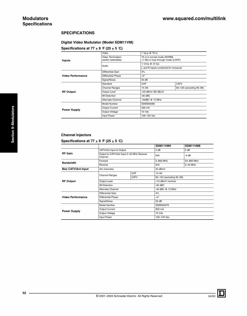
Modulators www.squared.com/multilinkSpecifications
52
Sec
tio
n 9
–Mo
du
lato
rs
SPECIFICATIONS
Digital Video Modulator (Model SDM11VM)
Channel Injectors
Specifications at 77 + 9 °F (25 + 5 °C)
Inputs
Video 1 Vp-p @ 75 Ω
Video Termination (switch selectable)
75 Ω in normal mode (NORM)>1 MΩ in loop through mode (LOOP)
Audio1 Vrms @ 47 kΩ
L and R inputs combined for monaural
Video PerformanceDifferential Gain 4%
Differential Phase <4°
Signal/Noise 55 dB
RF Output
Standard UHF CATV
Channel Ranges 14–69 65–125 (excluding 95–99)
Output Level +25 dBmV (85 dBuV)
IM Distortion -60 dBC
Alternate Channel -45dBC @ 12 MHz
Power Supply
Model Number SDM350086
Output Current 300 mA
Output Voltage 15 Vdc
Input Power 105–125 Vac
Specifications at 77 + 9 °F (25 + 5 °C)SDM11VMH SDM11VMB
RF GainCATV/Ant Input to Output 2 dB 2 dB
Output to CATV/Ant Input 5–42 MHz Reverse Channel
N/A -4 dB
BandwidthForward 5–806 MHz 54–806 MHz
Reverse N/A 5–42 MHz
Max CATV/Ant Input (64 channels) 20 dBmV
RF Output
Channel RangesUHF 14–64
CATV 65–125 (excluding 95–99)
Output Level +12 dBmV nominal
IM Distortion -60 dBC
Alternate Channel -45 dBC @ 12 MHz
Video PerformanceDifferential Gain 4%
Differential Phase <4°
Signal/Noise 55 dB
Power Supply
Model Number SDM350079
Output Current 600 mA
Output Voltage 15 Vdc
Input Power 105–125 Vac
© 2001–2003 Schneider Electric All Rights Reserved 04/03

www.squared.com/multilink ModulatorsSpecifications
04/03
Sec
tio
n 9
–Mo
du
lato
rs
Set Top Modulators (Models SDM21VT, SDM21VTST, SDM41VT, and SDM41VTST)
Specifications at 77 + 9 °F (25 + 5 °C)
InputsVideo 1 Vp-p @ 75 Ω
Audio 1 Vrms @ 47 kΩ
Video PerformanceDifferential Gain 4%
Differential Phase <4°
Signal/Noise 55 dB
RF Output
Standard UHF CATV
Channel Ranges 14–64 65–125 (excluding 95–99)
Output Level +25 dB mV
IM Distortion -60 dBC
Alternate Channel -45 dBC @ 12 MHz
Power Supply
Modulator Model SDM21VT SDM41VT SDM21VTST SDM41VTST
Output Current 600 mA 900 mA 900 mA 900 mA
Model Number SDM350079 SDM350082 SDM350082 SDM350082
Output Voltage 15 Vdc
Input Power 105–125 Vac
MTS Audio Performance (models SDM21VTST and SDM41VTST)
Frequency Range 20 Hz–12 kHz
Signal/Noise 65 dB
Separation 25 dB @ 1000 Hz
Surround Sound compatible with Dolby full logic surround sound
Noise Reduction certified dbx
53© 2001–2003 Schneider Electric All Rights Reserved

Modulators www.squared.com/multilinkSpecifications
© 2001–2003 Schneider Electric All Rights Reserved54
04/03
Sec
tio
n 9
–Mo
du
lato
rs

www.squared.com/multilink Video Cameras
04/03 © 20
Sec
tio
n 1
0–V
ideo
Cam
eras
VIDEO CAMERAS
SDM1VC or SDM1VCC
SDM2VC
SDM2VCC
Product DescriptionPRODUCT DESCRIPTION
Video Cameras (Models SDM1VC, SDM1VCC, SDM2VC and SDM2VCC)
The cameras must be used with the companion channel injectors (models SDM11VMH or SDM11VMB). The video signal received from the camera is modulated by the channel injector to create a new channel to add to the existing television channels.
The video camera is connected to the channel injector by a single run of CAT-5 or CAT-5E wire.
Features:
• SDM1VC and SDM1VCC are solid state, wide-angle cameras designed to fit in a single-gang junction box for exterior or interior installation
• SDM2VC and SDM2VCC are solid state, wide-angle cameras designed to fit double-gang junction boxes for exterior or interior installation
• Uses CAT-5/5E wire for use with the SDM11VM(H/B) series channel injector
• 78° viewing angle coverage
• Automatic white balance
• NTSC format (models SDM1VCC and SDM2VCC)
• EIA format (models SDM1VC and SDM2VC)
• Weather resistant seals and a paintable brass finish (models SDM1VC and SDM1VCC)
• Drip cap and gasket for outside installation (models SDM2VC and SDM2VCC)
• Smoked front panel (models SDM2VC and SDM2VCC)
• Screw terminal connectors
• Power is supplied by the channel injector
5501–2003 Schneider Electric All Rights Reserved

Video Cameras www.squared.com/multilinkGeneral Information and Application Data
56
Sec
tio
n 1
0–V
ideo
Cam
eras
GENERAL INFORMATION AND APPLICATION DATA
Camera Installation
Weather Resistant Video Cameras (Models SDM1VC and SDM1VCC)
The weather resistant video cameras are easily mounted into a single-gang junction box using the supplied single-gang gasket. The camera “looks” straight out from the cover plate. For a front door application, place the camera lens approximately 66 in. (1676.4 mm) off the ground, adjacent to the door. The camera lens cannot be adjusted.
In-Wall Video Cameras (Models SDM2VC and SDM2VCC)
The in-wall video cameras can be installed inside or outside. For outside installation, the video camera is mounted in a two-gang junction box using the supplied drip cap and gasket. The camera works best when “looking” down on the subject. For a front door application, place the camera lens approximately 7 ft (2.1 m) off the ground, adjacent to the door. The camera lens can be adjusted up and down.
Standardsingle-gangjunctionbox
Junctionbox
Gasket
Cameraplate
Junctionbox
Gasket
Cameraplate
6-32 x 1in.screws(included)
CAT-5 or CAT-5E cable
Drip capGasket
Frame
Add RTV to seal from weather
6-32 x 1in.screws(included)
Insert top screws
Deep two-gangJ-box
CAT-5 or CAT-5E cable
Drip capGasket
Frame
Attach drip cap, gasket, and frame
Wire terminals and insert camera at an angle and rotate into place.
© 2001–2003 Schneider Electric All Rights Reserved 04/03

www.squared.com/multilink Video Cameras
04/03
Sec
tio
n 1
0–V
ideo
Cam
eras
General Information and Application Data
For interior installation, the video camera is mounted into drywall using the supplied CADDY® bracket.
Video Camera Connection to Channel Injector Via Data Hub
The video cameras can be connected to the channel injector by two methods. The first method is connecting the video camera directly to a CAT-5/5E data hub (model SDM8D) 110 punch-down block and running an RJ-45 patch cord (included) from the data hub RJ-45 jack to the channel injector RJ-45 jack. The second method is wiring the camera directly to the eight-position terminal block on the channel injector. When wiring to the eight-position terminal block, match CAT-5 or CAT-5E wires to top row of color block and remove the default resistor. If using quad wire, match wiring to bottom row of color bar and leave default resistor in place.
CADDY bracket®frame
Drywall
InserttopscrewsCADDY
bracket
Square D model SDM8DData Hub ( 8 cables, TIA-568A) Category 5 Compliant
Link/normal
10 base-t hub
1 2 3 4 5
Square D modelH SDM5DENetwork hub 10 base-t
Output
Program
CATV/Ant Power
Channel Injector
CAT-5 video
DSL sent to home office computer only
Ethernet connection from home officeFour ethernet connections
CAT-5 data hub(model SDM8D)
Ethernet hub(model SDM5DE)
Channel injector(model SDM11VMH)
Cablesconnectingto data jacksin five wall plates
DSL fromphonecompany
Antenna orincoming cable
Power supply(model SDM350079)
Camera signal connects to channel injectorby way of the RJ-45patch cord
Power
Camera wire
Cable connectingto phone jack
Power supply-included(model SDM350087)
57© 2001–2003 Schneider Electric All Rights Reserved

Video Cameras www.squared.com/multilinkGeneral Information and Application Data
58
Sec
tio
n 1
0–V
ideo
Cam
eras
NOTE: The channel injector was designed to work with CAT-5/5E wiring. Although the system will function with quad wire, CAT-5/5E wiring will deliver the highest quality picture and allows the use of an automatic line length sensor and picture compensator.
Painting the Cover Plate of Weather Resistant Cameras
The brass cover plate can be painted to match any exterior house paint. The brass cover plate is ready to paint after sanding and applying exterior use metal primer.
Channel Injector and CAT-5/5E Cable Length Limitations
The length of the CAT-5/5E cable that runs between the channel injector and the video cameras must not exceed the maximum cable lengths listed in the table below.
FCC Requirements
These products comply with Part 15 of the FCC rules. Operation is subject to the following two conditions: these devices may not cause harmful interference, and these devics must accept any interference received, including interference that may cause undesired operation.
Installation Requirements
FCC classifies this product under Part 15 of its rules as a "television interface device.” Systems designed using television interface devices have the following legal requirements:
1. The modulated channel signal strength may not exceed 15.56 dBmV at any television (Federal Regulation 47CFR15.115(b)(1)(i)).
2. If an antenna is used in the system, the modulated channel signal strength may not exceed -51dBmV at the antenna input port (Federal Regulation 47CFR15.115(c)(4)).
NOTE TO INSTALLER: The system you design must comply with these regulations. As the installer, you are responsible. The video cameras (when used with an SDM11VMH or SDM11VMD channel injector) have the necessary characteristics to comply with the above requirements as designed without additional accessories. The model SDM11VMH is suitable for use with an antenna or with CATV systems.The model SDM11VMB is suitable for use with CATV systems only.
Cable Connection Length Limitations
ConnectionsMaximum Cable Length
From To
Black and white camera (SDM1VC and SDM2VC) Channel Injector or CAT-5/5E data hub 300 ft (91.4 m)
Color camera (SDM1VCC and SDM2VCC) Channel Injector or CAT-5/5E data hub 100 ft (30.5 m)
© 2001–2003 Schneider Electric All Rights Reserved 04/03

www.squared.com/multilink Video Cameras
04/03
Sec
tio
n 1
0–V
ideo
Cam
eras
Technical InformationTECHNICAL INFORMATION
Programming
Once a video camera is connected to a channel injector, programming a new channel with the channel injector (model SDM11VMH or SDM11VMB) is simple with the push button programming feature. The “Program” push button is used to enter the channel digits. For a programming example, see the following figure. The example uses channel 120.
SPECIFICATIONS
Video Cameras
Specifications at 77 + 9 °F (25 + 5 °C)SDM1VC SDM2VC SDM1VCC SDM2VCC
Image Format EIA (black and white) NTSC (color)
Resolution, Horizontal 525 lines
Resolution 350 lines
Minimum Illumination 0.3 lux 2 lux 6 lux 8 lux
Signal to Noise Ratio >45 dB
AGC Yes
Lens 3.6 mm F2.0
Lens Viewing Angle 78°
White Balance automatic
Electronic Shutter Speed 1/60 to 1/50,000 second
Maximum Cable Length to Channel Injector or CAT-5/5E Data Hub
300 ft (91.4 m) 100 ft (30.5 m)
Ambient Temperature Operating Range -10° C to +50° C (+14° F to +122° F)
Press button
time
program1
Press button
more times
program2
Press button
more times
program10
Wait for LED(ready for next number.)
power
(press 10 toenter a ‘zero’)
Wait for LED(ready for next number.)
power
LED comes back on whendone. If an incorrect channel
is entered, LED will flashquickly and return to the
previous setting.
Step 1
Step 2
Step 3
Step 4
Step 5
Step 6
59© 2001–2003 Schneider Electric All Rights Reserved

Video Cameras www.squared.com/multilinkSpecifications
60
Sec
tio
n 1
0–V
ideo
Cam
eras
© 2001–2003 Schneider Electric All Rights Reserved 04/03

www.squared.com/multilink Video Wall Plate
04/03 © 20
Sec
tio
n 1
1–V
ideo
Wal
l Pla
te
VIDEO WALL PLATE
SDM1VWP
12:0012:00
POWER
POWER
LOOP
LOOP
NORM
NORM
AUDIO R
AUDIO L
VIDEO
Satellite receiver
Audio inputs
Video input
Audio/video outputs
Audio receiver
Video wall plate(model SDM1VWP)
Localtelevision
Product DescriptionPRODUCT DESCRIPTION
Video Wall Plate (Model SDM1VWP)
The video wall plate (model SDM1VWP) is a companion piece to the channel injector module. Using the video wall plate, any audio/video device with RCA connections can be connected to the channel injector using a single run of CAT-5 or CAT-5E wire. No coaxial cables or additional power wires are needed.
The video wall plate provides switchable 75 ohm or Hi-Z termination for loop-through capability. The looped video output can be fed to a local monitor or VCR.
Features:
• Uses CAT-5/5E wire for use with SDM11VM(B/H) series channel injectors
• Switchable 75 ohm, or Hi-Z terminations for loop-through
• Looped video output for monitor or VCR
• Uses Decora style wall plates
• Uses screw terminal connectors (in rear, for CAT-5/5E termination)
• Accepts any type of video input from a camera or other video device with RCA connections
GENERAL INFORMATION AND APPLICATION DATA
Connecting Video Wall Plate to Video Source
The video wall plate connection to a video source is completed using RCA type connector cables.
NOTE: When the video wall plate is wired to a channel injector, the channel injector and the video wall plate can be powered from either location. However, the video wall plate does not come with a source of power, so the power supply from the channel injector must be used.
Operating Controls
Control Description
POWERThe green power LED will be lit showing active power when the power supply is plugged into either the video wall plate or the channel injector.
NORMSelect NORM when a television or audio/video receiver is not used at the wall plate to view the connected source. The NORM position terminates the video source with 75 Ω .
LOOPSelect LOOP when a television or audio/video receiver is connected to the wall plate to view the connected source. The LOOP position leaves the source unterminated. The local monitor will provide termination.
6101–2003 Schneider Electric All Rights Reserved

Video Wall Plate www.squared.com/multilinkGeneral Information and Application Data
© 2062
Sec
tio
n 1
1–V
ideo
Wal
l Pla
te
CAT-5 video
Channel injector (model SDM11VMH or SDM11VMB)
Power the channel injecto(model SDM11VMH or SDM1VWP) last.Make all cables andCAT-5 connections first.
Connect antenna or incomingcable to channel injector (model SDM11VMH) input.
Connect channel injector (model SDM11VMH) output to splitter or distribution panel input.
CAT-5 cable
Video wall plate (model SDM1VWP)(Rear view)
Video Wall Plate Connection to Channel Injector
The video wall plate can be connected to the channel injector by two methods. The first method is by connecting the video wall plate directly to a CAT-5/5E data hub (model SDM8D)110 punch-down block and running an RJ-45 patch cord (included) from the data hub RJ-45 jack to the channel injector RJ-45 jack. The second method is wiring the video wall plate directly to the eight-position terminal block on the channel injector. When wiring to the eight-position terminal block, match CAT-5 or CAT-5E wires to top row of color block and remove default resistor. If using quad wire, match wiring to bottom row of color bar and leave default resistor in place.
NOTE: The channel injector was designed to work with CAT-5/5E wiring. Although the system will function with quad wire, CAT-5/5E wiring will deliver the highest quality picture and allows the use of an automatic line length sensor and picture compensator.
Channel Injector and CAT-5/5E Cable Length Limitations
The length of the CAT-5/5E cable that runs between the channel injector and the video wall plate must not exceed 100 ft (30.5 m).
FCC Requirements
These products comply with Part 15 of the FCC rules. Operation is subject to the following two conditions: these devices may not cause harmful interference, and these devics must accept any interference recieved, including interference that may cause undesired operation.
Installation Requirements
FCC classifies this product under Part 15 of its rules as a “television interface device.” Systems designed using television interface devices have the following legal requirements:
1. The modulated channel signal strength may not exceed 15.56 dBmV at any television (Federal Regulation 47CFR15.115(b)(1)(i)).
2. If an antenna is used in the system, the modulated channel signal strength may not exceed -51dBmV at the antenna input port (Federal Regulation 47CFR15.115(c)(4)).
NOTE TO INSTALLER: The system you design must comply with these regulations. As the installer, you are responsible. The video wall plate (when used with an SDM11VMH or SDM11VMB channel injector) has the necessary characteristics to comply with the above requirements as designed without additional accessories. The model SDM11VMH is suitable for use with an antenna or with CATV systems.The model SDM11VMB is suitable for use with CATV systems only.
r
01–2003 Schneider Electric All Rights Reserved 04/03

www.squared.com/multilink IR Target and Emitter
04/03 ©
Sec
tion
12–I
R T
arg
et a
nd
Em
itter
SDM1VIR
SDM2VIR
IR TARGET AND EMITTER
Product DescriptionPRODUCT DESCRIPTION
IR Target (Model SDM1VIR)
Features:
• Controls DVD, VCR and DSS players
• 5-volt target
• Locate at television
IR Emitter (Model SDM2VIR)
Features:
• Controls DVD, VCR and DSS players
• 5-volt emitter
• Compatible 12- and 5-volt IR systems
• Adhesive backed single head emitter
• Locate at video source
GENERAL INFORMATION AND APPLICATION DATA
IR Repeating System
The high headroom amplifier and bi-directional amplifier video hubs (models SDM38VBIR and SDM38VHIR) and the set top modulators (models SDM21VT, SDM41VT, SDM21VTST, and SDM41VTST) have integrated 5-volt IR engines that pass IR information, allowing remote control of any video device from any location when the IR target and IR emitter are used.
To control the video devices, an IR target (model SDM1VIR) and an IR emitter (model SDM2VIR) are connected to the modules. For example, when the remote control is pointed to the IR target located at the television, the IR pulses are repeated by the emitter, which is controlling the DVD player located in a remote area.
Televisions
+12vd
c
Gnd IR
Modulators
A
B+Pwr
Typical remote control
IR emitter(model SDM2VIR)
IR target(model SDM1VIR)
Set top modulator
Video hub (model SDM38VHIR)
63 2001–2003 Schneider Electric All Rights Reserved

IR Target and Emitter www.squared.com/multilinkGeneral Information and Application Data
© 2064
Sec
tion
12–I
R T
arg
et a
nd
Em
itter
01–2003 Schneider Electric All Rights Reserved 04/03

www.squared.com/multilink Accessories
04/03 ©
Sec
tio
n 1
3–A
cces
sori
es
SDM1A
SDM6A
SDM1DC
SDM2DC
Product DescriptionPRODUCT DESCRIPTION
Low Pass Filter (Model SDM600LPF)
Features:
• Used to “clear” channels so that modulated signals can be added to the system
• Filter begins to remove programming starting at channel 85
• Modulated signals can be added above channel 91
Video Signal Attenuator (Models SDM2503 and SDM2506)
Features:
• Used to reduce signal strength
• SDM2503 reduces signal by 3dB
• SDM2506 reduces signal by 6dB
Amplifier Adapter (Model SDM1A)
The adapter mounts to any enclosure grid. The adapter allows ChannelPlus amplifiers (models 3400 and 8200) to mount into the enclosure grid. The adapter requires 2 in. (51 mm) of grid mounting space in the enclosure.
Six-Connector Adapter (Model SDM6A)
The adapter allows for a combination of eight keystone connectors (CAT-5/5E) or six coaxial barrel connections. The adapter requires 2 in. (51 mm) of grid mounting space in the enclosure.
Features:
• Mounts to any enclosure grid
• Eight CAT-5/5E connectors
• Six coaxial connectors
Isolation Mounting Brackets (Models SDM1IMB and SDM2IMB)
Features:
• Universal mounting plate for products that are not Square D Multi-Link brand
• Works with audio multi-zone amps, security panels and home automation controllers
• Adjustable for mounting patterns from 4.5 in. (114.3 mm) to 10.5 in. (266.7 mm) wide
• Heavy duty bracket (model SDM1IMB) load rated 60 pounds
• Light duty bracket (model SDM2IMB) load rated 10 pounds
• Isolated to prevent ground loops
CAT-5/5E Patch Cords (Models SDM1DC and SDM2DC)
The patch cords are available in two sizes, a one foot cord and a two foot cord. The cords can be used with data hubs (models SDM8D, SDM8DB, and SDM5DE), telephone hubs (models SDM46P and SDM48PX), and channel injectors (models SDM11VMH and SDM11VMB).
652001–2003 Schneider Electric All Rights Reserved
Accessories www.squared.com/multilinkProduct Description
© 266
Sec
tio
n 1
3–A
cces
sori
es
Coupling Tube (Model SDM2C)
Features:
• Stack multi-link enclosures
• 2 in. (59 mm) conduit size passes cables from enclosure to enclosure
• No limits on number coupled
• Automatically spaces enclosure 2 in. (59 mm) apart
• Use up to four coupling tubes per enclosure
Replacement Snap Locks (Model SDM10SL)
Features:
• Ten replacement snap locks per package
Power Supply
Channel Injectors and Two-Input Set Top Modulators (Model SDM350079)
Used on the following modules:
• Channel injectors (models SDM11VMB and SDM11VMH)
• Dual set top modulator (model SDM21VT)
Four-Input and MTS Stereo Set Top Modulators (Model SDM350082)
Used on the following modules:
• Quad set top modulator (model SDM41VT)
• Dual and quad MTS stereo sound set top modulators (models SDM21VTST and SDM41VTST)
Video Hubs (Model SDM350086)
Used on the on the following modules:
• Video hubs (models SDM38VBIR and SDM38VHIR)
• Modulator combiner (model SDM81VC)
• Video amplifier hub (model SDM16VAB)
• Video modulator (model SDM11VM)
Ethernet Hub (Model SDM350087)
Used on the Ethernet hub (model SDM5DE).
Adapter Cable (Model SDM532172)
Used on the following modules:
• Video hubs (models SDM38VBIR and SDM38VHIR)
• Modulator combiner (model SDM81VC)
• Video amplifier hub (model SDM16VAB)
• Video modulator (model SDM11VM)
001–2003 Schneider Electric All Rights Reserved 04/03

www.squared.com/multilink AccessoriesProduct Description
04/03 © 2
Sec
tio
n 1
3–A
cces
sori
es
SDM12WS
Wire Spacer (Model SDM12WS)
Features:
• Connects to the grid on SDM18BW or SDM36BW enclosures
• Lifts modules one inch (25.4 mm) above the grid
• Repeats grid pattern
• Provides wire management channel
• 11.2 in. (285 mm) high and 6.5 in. (165.1 mm) wide
The wire spacer, due to panel depth limitations, cannot be used to mount the following modules:
• Video hubs (models SDM38VHIR/BIR)
• Modulator combiner (model SDM81VC)
• Modulator (model SDM11VM)
• Channel injectors (models SDM11VMH/MB)
• Satellite multi-switch (model SDM24VD)
• Accessory adapters (models SDM1A or SDM6A)
• Video splitter (model SDM18VS)
67001–2003 Schneider Electric All Rights Reserved
Accessories www.squared.com/multilinkProduct Description
© 2068
Sec
tio
n 1
3–A
cces
sori
es
01–2003 Schneider Electric All Rights Reserved 04/03
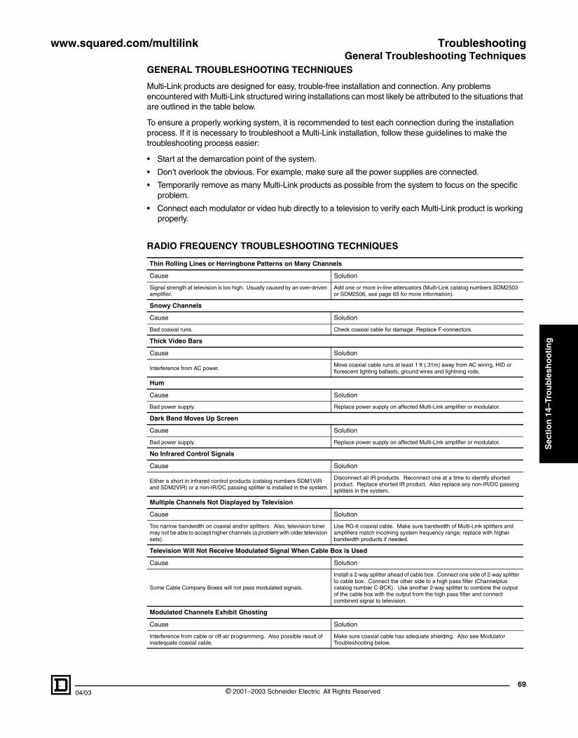
www.squared.com/multilink Troubleshooting
04/03
Sec
tio
n 1
4–Tr
ou
ble
sho
oti
ng
TROUBLESHOOTING
General Troubleshooting Techniques
69
GENERAL TROUBLESHOOTING TECHNIQUES
Multi-Link products are designed for easy, trouble-free installation and connection. Any problems encountered with Multi-Link structured wiring installations can most likely be attributed to the situations that are outlined in the table below.
To ensure a properly working system, it is recommended to test each connection during the installation process. If it is necessary to troubleshoot a Multi-Link installation, follow these guidelines to make the troubleshooting process easier:
• Start at the demarcation point of the system.
• Don’t overlook the obvious. For example, make sure all the power supplies are connected.
• Temporarily remove as many Multi-Link products as possible from the system to focus on the specific problem.
• Connect each modulator or video hub directly to a television to verify each Multi-Link product is working properly.
RADIO FREQUENCY TROUBLESHOOTING TECHNIQUES
Thin Rolling Lines or Herringbone Patterns on Many Channels
Cause Solution
Signal strength at television is too high. Usually caused by an over-driven amplifier.
Add one or more in-line attenuators (Multi-Link catalog numbers SDM2503 or SDM2506, see page 65 for more information).
Snowy Channels
Cause Solution
Bad coaxial runs. Check coaxial cable for damage. Replace F-connectors.
Thick Video Bars
Cause Solution
Interference from AC power.Move coaxial cable runs at least 1 ft (.31m) away from AC wiring, HID or florescent lighting ballasts, ground wires and lightning rods.
Hum
Cause Solution
Bad power supply. Replace power supply on affected Multi-Link amplifier or modulator.
Dark Band Moves Up Screen
Cause Solution
Bad power supply. Replace power supply on affected Multi-Link amplifier or modulator.
No Infrared Control Signals
Cause Solution
Either a short in infrared control products (catalog numbers SDM1VIR and SDM2VIR) or a non-IR/DC passing splitter is installed in the system.
Disconnect all IR products. Reconnect one at a time to identify shorted product. Replace shorted IR product. Also replace any non-IR/DC passing splitters in the system.
Multiple Channels Not Displayed by Television
Cause Solution
Too narrow bandwidth on coaxial and/or splitters. Also, television tuner may not be able to accept higher channels (a problem with older television sets).
Use RG-6 coaxial cable. Make sure bandwidth of Multi-Link splitters and amplifiers match incoming system frequency range; replace with higher bandwidth products if needed.
Television Will Not Receive Modulated Signal When Cable Box is Used
Cause Solution
Some Cable Company Boxes will not pass modulated signals.
Install a 2-way splitter ahead of cable box. Connect one side of 2-way splitter to cable box. Connect the other side to a high pass filter (Channelplus catalog number C-BCK). Use another 2-way splitter to combine the output of the cable box with the output from the high pass filter and connect combined signal to television.
Modulated Channels Exhibit Ghosting
Cause Solution
Interference from cable or off-air programming. Also possible result of inadequate coaxial cable.
Make sure coaxial cable has adequate shielding. Also see Modulator Troubleshooting below.
© 2001–2003 Schneider Electric All Rights Reserved

Troubleshooting www.squared.com/multilinkGeneral Troubleshooting Techniques
70
Sec
tio
n 1
4–Tr
ou
ble
sho
oti
ng
RADIO FREQUENCY TROUBLESHOOTING TECHNIQUES (CONTINUED)
MODULATOR TROUBLESHOOTING FOR CAMERAS
If the modulated channel is not displayed on the television or if the modulated channel is displayed on the television but exhibits ghosting or herringbone patterns, follow the guidelines below:
1. Make sure the channel programmed on the modulator matches the mode to which the television is set. For example, if the modulator is programmed to a channel between channel 14 and channel 69, then make sure the television is set for off air programming. If the modulator is programmed to a channel between channel 69 and channel 125, make sure the television is set for cable television.
2. With the modulator disconnected from the structured wiring system and the incoming cable or antenna signal connected to the structured wiring system, run the autoprogram on the television set. Autoprogram will detect all “used” channels. Make sure the modulator is programmed to a channel which autoprogram did not detect, i.e., an “unused” channel.
3. Connect the modulator output directly to one television and remove the cable or antenna signal from the structured wiring system.
4. If the modulated signal is displayed on the television, then the incoming cable or antenna signal is interfering with the modulated signal. To correct this problem, a filter must be inserted on the incoming signal to clear any cable signal from desired modulated channel. For the filter, see page page 65.
5. If, when the cable or antenna signal is removed from the structured wiring system, the modulated signal does not show up on the television, then the problem may lie with the television set or a cable run. With the cable or antenna signal removed, connect the modulator output to another television set. If the problem still exists, check the relevant coaxial runs for any damage or improperly installed connectors.
Modulated Channel Displays all Snow on Television
Cause Solution
Television tuner and modulator are not set on the same mode (UHF vs VHF). See Modulator Troubleshooting below.
Modulated Channel is a Black Picture on Television
Cause Solution
Modulator is working, but connections from video source to modulator are incorrect.
Make sure video source is powered. Verify good connections from video source (VCR, DVD, etc.) to modulator. Verify video source is working by connecting directly to television. Also see the section Modulator Troubleshooting for Cameras below.
Modulated Channel Exhibits Herringbone Patterns
Cause Solution
Interference from cable or off-air programming. See the section Modulator Troubleshooting for Cameras below.
© 2001–2003 Schneider Electric All Rights Reserved 04/03

www.squared.com/multilink Glossary
Sec
tio
n 1
5–G
loss
ary
Structured Wiring TermsSTRUCTURED WIRING TERMS
Adjacent channels Two television channels having video carriers 6 MHz apart or two FM channels having carriers occupying neighboring allocations.
ADSL (Asymmetrical Digital Subscriber Line) Providing a high-speed Internet connection via an incoming telephone line and modems.
Amplifier A device used to increase the power and voltage level of a signal.
ATSC (Advanced Television Systems Committee) An international organization establishing voluntary technical standard for advanced television systems.
Attenuation The decrease in magnitude of a signal as it travels through a transmission medium such as a coaxial cable.
Attenuator A passive device used to reduce signal strength.
Bandwidth The range of frequencies required for proper transmission of a signal. Expressed in Hertz (cycles per second). The higher the bandwidth, the more information that can be carried.
Baseband A transmission method in which the entire bandwidth is used to transmit a single digital signal. The signal has not been modulated onto a carrier (i.e. Hi-Fi Audio, NTSC video, or RS-232 data).
BID (Bi-directional) Systems used with CATV services using pay-per-view or cable modems. BID is not for use with off-air antennas.
Bit One binary digit.
BPS (Bits Per Second) A measurement of data transmission speed.
Broadband A transmission method having a bandwidth sufficient to carry multiple voice, video, or data signals simultaneously. Each channel is modulated to a different frequency bandwidth on the transmission medium and is demodulated to its original frequency at the receiving end. This technique is used to provide many CATV channels on one coaxial cable.
Category rated Twisted pair communications circuits are rated by category, whose specifications are covered under EIA/TIA 568. The higher the category number, the higher the information capacity of the circuit.
Category 5 See “Category Rated.” For modern telephone/data transmission, Category 5, 4-UTP (four unshielded twisted wire pairs) is recommended. Data transmission at frequencies up to 100 MHz.
Category 5E See “Category 5.” Improved specifications for near-end cross talk and attenuation.
CATV (Community Antenna Television, cable television) A radio frequency distribution system which distributes television broadcast programs, original programs, premium programming and other services using a network of coaxial cable.
Channel In television, a portion of the radio frequency spectrum that is 6 MHz wide and carries the audio and video carriers of the television signal.
CO (Central Office) A reference to the local telephone exchange carrier.
Coaxial cable A concentric cable consisting of a center conductor, a dielectric, and a shield. Coaxial cable is used for most MATV and CATV work and has a characteristic impedance of 75 ohms.
Composite video signal The composite video signal including the picture (luminance) signal, the blanking and sync pulses, and the color (chrominance).
Cross connect The physical connection between patch panels or punch-down blocks that facilitates connections from systems and feeds to drops.
7104/03 © 2001–2003 Schneider Electric All Rights Reserved

Glossary www.squared.com/multilinkStructured Wiring Terms
Sec
tio
n 1
5–G
loss
ary
Crosstalk The unwanted introduction of signals from one channel to another.
Daisy Chain Wiring A wiring concept where multiple terminations of a branch wiring run are “looped” in parallel, interconnecting one location to the next.
Decibel Abbreviation dB. A logarithmic function used to simplify MATV calculations. Decibels may be added or subtracted. 0 dB is the standard reference level for all MATV calculations.
dB See “Decibel.”
dBmV An absolute signal level where 0 dBmV is equal to 1000 µV across 75 ohms.
Demarc (Demarcation Point) The point of interconnection between telephone company facilities and a building’s wiring.
Diplexer A device that combines RF frequencies (OFF-air or CATV) and satellite frequencies onto a single coaxial cable. Another diplexer would also be required to separate the signals at the point of use.
DIP switch (Dual Inline Package Switch) A manual means of selecting settings on an electronic circuit board.
DSL (Digital Subscriber Line) A service that offers a faster Internet connection than a standard dial-up connection. DSL technology uses existing two-wire copper telephone wiring to deliver high-speed data services to homes and businesses.
Egress A condition often called “signal leakage” in which signals carried by the distribution system radiate into the air.
EIA (Electronic Industry Association-formerly RMA or RETMA) An association of manufacturers and users that establishes standards and publishes test methodologies.
Ethernet Ethernet is a LAN (Local Area Network) technology protocol that transmits information between computers and peripherals at speeds of 10 and 100 Mbps (fast Ethernet). Currently, the most widely used version of Ethernet technology is the 10 Mbps.
F-connector A barrel-type connector used to terminate coaxial cable, such as RG-59, RG-6, or RG-6Q, for video applications.
Filter Filters are used to block out undesired frequencies. There are two types of filters: band pass and rejection. A band pass filter permits only the desired range to pass through, while the rejection filter attenuates and undesired range of frequencies.
Gain A measure of amplification of a device, usually expressed in dB at the highest frequency of operation.
Ghosting A signal interference condition producing positive or negative pictures displaced in time from the desired picture, caused by multi-path signal reception. Ghost pictures also result from cable ringing.
GigaHertz (GHz) A unit of measurement of frequency or bandwidth of one billion cycles per second.
HAN (Home Area Network) See “LAN.”
HDTV (High Definition Television) A high-resolution, wide-screen common picture format and transmission standard for bringing digital broadcast television to the home.
Head end The equipment located at the start of a CATV system. The place where the signals are processed and combined prior to distribution.
Hertz (Hz) The unit of measurement of frequency or bandwidth of one billion cycles per second.
HHR A high headroom amplifier used in high performance off-air antenna or non bi-directional CATV systems.
Homerun Wiring A wiring concept in which all branch wiring is run back to a central hub, or service entrance location.
Hub A central point to connect and distribute common information to multiple locations.
© 2001–2003 Schneider Electric All Rights Reserved72
04/03

www.squared.com/multilink GlossaryStructured Wiring Terms
Sec
tio
n 1
5–G
loss
ary
IDC (Insulation Displacement Connector) A type of wire terminating in which the wire is “punched down” into a metal holder which cuts into the wire insulation, making contact with the conductor.
Ingress A condition where unwanted RF signal leaks into a distribution system.
Insertion loss Also called “feed through loss.” This is the loss that occurs as signals pass through a passive device. Insertion loss occurs in all devices which do not amplify the signal.
IR signal Infrared signal, used to transmit functional commands to a remotely located device, such as a television, DVD, or VCR.
ISDN (Integrated Services Digital Network) Provides a user up to 56 kpbs of data bandwidth on a telephone line that is also used for voice, or up to 128 kbps if the line is only used for data.
KiloHertz (KHz) A unit of measurement of frequency or bandwidth of one thousand cycles per second.
LAN (Local Area Network) A group of computers and peripherals set up to communicate with each other.
LNB A low noise bandpass amplifier is located in the feed horn of a satellite dish and receives satellite signals that are reflected from the dish.
MATV (Master Antenna Television System) A distribution system which is usually contained within a single building and receives its signals from an antenna or CATV system.
Megabits (Mbps) Megabits (one billion bits) per second, a measurement of transmission speed.
MegaHertz (MHz) A unit of measurement of frequency or bandwidth of one million cycles per second.
Modulation Placing information, audio/video, onto a higher frequency carrier by means of amplitude, frequency, or phase adjustment.
MTS (Multi-Television Stereo)
NID (Network Interface Device)
NTSC (National Television System Committee) A national organization formed to establish standards with regards to commercial television transmissions.
Off-air Any channel which can be received by a conventional antenna system, including VHF and UHF broadcasts.
Patch cords The cords interconnecting terminations at the central distribution panel. Typically these cords are terminated with modular plugs.
Punch-Down block Refer to “110 Connector.”
RF (Radio Frequency) Generally refers to data modulated over a high-frequency carrier for wireless transmission.
RFI (Radio Frequency Interference)
RG-6 cable A coaxial cable used for broadband video applications. RG-6 has an 18 gauge center conductor, allowing a higher bandwidth than the RG-59 cable, which has a smaller 20 gauge center conductor. RG-6 uses standard “F” connectors for video equipment connections.
RG-6Q cable Quadruple, or “Quad Shield” cable, doubles the shielding of a standard RG-6 cable, using a second layer of foil and aluminum braid.
RJ-11 Voice grade modular interface (jacks and plugs), accepts one pair of conductors. Commonly used for single line telephones, answering machines, and modems.
7304/03 © 2001–2003 Schneider Electric All Rights Reserved

Glossary www.squared.com/multilinkS
ecti
on
15–
Glo
ssar
y
Structured Wiring Terms
RJ-14 Voice grade modulator interface (jacks and plugs), accepts two pairs of conductors. Commonly used for dual line telephones and answering machines.
RJ-25 Voice grade modular interface (jacks and plugs), accepts three pairs of conductors. Commonly used for KTS (Key Telephone System), a system that provides direct selection of an available line from a multiline telephone set.
RJ-31X Modular interface (jacks and plugs), used with security systems only.
RJ-45 Voice/data grade modular interface (jacks and plugs). Offering four pairs of connectors, RJ-45 is the interface of choice for all structured wiring installations.
Signal-to-noise ratio (SIN) The ratio of desired signal level to the undesired noise level, expressed in dB.
Signal strength The intensity of an RF signal measured in volts (V), millivolts (mV), microvolts (µV), or dBmV.
Snow A large quantity of random noise in a television picture which results from a poor CON (earner-to-noise) ratio.
Star Topology Wiring See “Homerun Wiring.”
Tap A device inserted into a feeder line which allows a specific amount of signal to be removed from the feeder line and isolates the TAP port from the main through line.
Terminator A resistive device which matches a cable, or the unused output of an active or passive system component to its characteristic impedance. Proper termination is required to prevent unused outputs from causing reflections back down the line.
TIA (Telecommunications Industry Association) Body which authored the TIA/EIA 568-A “Commercial Building Telecommunications Wiring Standard” in conjunction with EIA.
Tilt A linearized change in the frequency response of the CATV system caused primarily by the frequency dependent cable loss. Tilt is quantified by comparing the difference between the level of the highest channel’s video carrier and that of the lowest channel.
UHF (Ultra High Frequency) Off-air television channel 14 through 69.
UTP (Unshielded Twisted Pair) Twisted pair cable without either individual or overall shielding.
VHF (Very High Frequency) Off-air television channels 2 through 13.
10 BASE-T 10 Mbps 802.3/Ethernet over standard unshielded twisted pair cable specification. 10 BASE-T supports network configurations over twisted pair transmission systems up to 100 meters in length without the use of a repeater.
100 BASE-T See “10 BASE-T,” except rated for 100 Mbps (fast Ethernet).
110 connector An Insulation Displacement Connection (see “IDC”) system used to terminate telephone and data cables. Commonly referred to as a 110 connector or 110 punch-down. A 110 punch-down tool is required to terminate the cable in the connector terminals.
© 2001–2003 Schneider Electric All Rights Reserved74
04/03

Index
04/03
Sec
tio
n 1
6–In
dex
Index
Aaccessoriesadapter cable . . . . . . . . . . . . . . . . . . . . . . . . . . . . . . . . . . . . . . . . . . . . . . . . . . . . . . . . . . . . . . 66
amplifier adapter . . . . . . . . . . . . . . . . . . . . . . . . . . . . . . . . . . . . . . . . . . . . . . . . . . . . . . . . . . . 65
CAT-5/5E patch cords . . . . . . . . . . . . . . . . . . . . . . . . . . . . . . . . . . . . . . . . . . . . . . . . . . . . . . 65
coupling tube . . . . . . . . . . . . . . . . . . . . . . . . . . . . . . . . . . . . . . . . . . . . . . . . . . . . . . . . . . . . . 66
isolation mounting brackets . . . . . . . . . . . . . . . . . . . . . . . . . . . . . . . . . . . . . . . . . . . . . . . . . . . . . . . . 65
low pass filter . . . . . . . . . . . . . . . . . . . . . . . . . . . . . . . . . . . . . . . . . . . . . . . . . . . . . . . . . . . . . . . . . . . . 65
replacement snap locks . . . . . . . . . . . . . . . . . . . . . . . . . . . . . . . . . . . . . . . . . . . . . . . . . . . . . 66
six-connector adapter . . . . . . . . . . . . . . . . . . . . . . . . . . . . . . . . . . . . . . . . . . . . . . . . . . . . . . . . . . . . . 65
wire spacer . . . . . . . . . . . . . . . . . . . . . . . . . . . . . . . . . . . . . . . . . . . . . . . . . . . . . . . . . . . . . . . . . . . . . . 67
Bbridgeable CAT-5/5E hub . . . . . . . . . . . . . . . . . . . . . . . . . . . . . . . . . . . . . . . . . . . . . . . . . . . . . . . 28
CCAT-5 jack . . . . . . . . . . . . . . . . . . . . . . . . . . . . . . . . . . . . . . . . . . . . . . . . . . . . . . . . . . . . . . . . . . 10
Category 5 and 5E cable . . . . . . . . . . . . . . . . . . . . . . . . . . . . . . . . . . . . . . . . . . . . . . . . . . . . . . . . 5
channel injectors . . . . . . . . . . . . . . . . . . . . . . . . . . . . . . . . . . . . . . . . . . . . . . . . . . . . . .46–47, 50, 52
combination hubs . . . . . . . . . . . . . . . . . . . . . . . . . . . . . . . . . . . . . . . . . . . . . . . . . . . . . . . . . . . . . 25
Ddata termination hub . . . . . . . . . . . . . . . . . . . . . . . . . . . . . . . . . . . . . . . . . . . . . . . . . . . . . . . . . . . 28
dual LNB 18 in. satellite dish . . . . . . . . . . . . . . . . . . . . . . . . . . . . . . . . . . . . . . . . . . . . . . . . . . . . 41
Eenclosures and brackets
AC power accessories . . . . . . . . . . . . . . . . . . . . . . . . . . . . . . . . . . . . . . . . . . . . . . . . . . . . . . . . . . 21–23
cover . . . . . . . . . . . . . . . . . . . . . . . . . . . . . . . . . . . . . . . . . . . . . . . . . . . . . . . . . . . . . . . . . . . . 19
enclosures . . . . . . . . . . . . . . . . . . . . . . . . . . . . . . . . . . . . . . . . . . . . . . . . . . . . . . . . . . . . . . 6, 20, 22–23
universal mounting bracket . . . . . . . . . . . . . . . . . . . . . . . . . . . . . . . . . . . . . . . . . . . . . . . . . . . . . . . . 19
Ethernet hub . . . . . . . . . . . . . . . . . . . . . . . . . . . . . . . . . . . . . . . . . . . . . . . . . . . . . . . . . . . . . . 29–30
Gglossary . . . . . . . . . . . . . . . . . . . . . . . . . . . . . . . . . . . . . . . . . . . . . . . . . . . . . . . . . . . . . . . . . 71–74
HHDTV dual-dual LNB 24 in. satellite dish . . . . . . . . . . . . . . . . . . . . . . . . . . . . . . . . . . . . . . . . . . . 42
75© 2001–2003 Schneider Electric All Rights Reserved

Index
76
Sec
tio
n 1
6–In
dex
IIR emitter . . . . . . . . . . . . . . . . . . . . . . . . . . . . . . . . . . . . . . . . . . . . . . . . . . . . . . . . . . . . . . . . . . . 63
IR target . . . . . . . . . . . . . . . . . . . . . . . . . . . . . . . . . . . . . . . . . . . . . . . . . . . . . . . . . . . . . . . . . . . . 63
Mmodular connectors . . . . . . . . . . . . . . . . . . . . . . . . . . . . . . . . . . . . . . . . . . . . . . . . . . . . . . . . . . . . . 9
modulator combiner hub . . . . . . . . . . . . . . . . . . . . . . . . . . . . . . . . . . . . . . . . . . . . . . . . . . . . . 37, 39
modulators. . . . . . . . . . . . . . . . . . . . . . . . . . . . . . . . . . . . . . . . . . . . . . . . . . . . . . . . . . . . . . . . . . . 45
Ppower supply
channel injectors and two-input set top modulators. . . . . . . . . . . . . . . . . . . . . . . . . . . . . . . . . 66
Ethernet hub . . . . . . . . . . . . . . . . . . . . . . . . . . . . . . . . . . . . . . . . . . . . . . . . . . . . . . . . . . . . . . 66
four-input and MTS stereo set top modulators . . . . . . . . . . . . . . . . . . . . . . . . . . . . . . . . . . . . 66
video hubs . . . . . . . . . . . . . . . . . . . . . . . . . . . . . . . . . . . . . . . . . . . . . . . . . . . . . . . . . . . . . . . . 66
pre-wire schemes
audio/video and television . . . . . . . . . . . . . . . . . . . . . . . . . . . . . . . . . . . . . . . . . . . . . . . . . . . . 7
data . . . . . . . . . . . . . . . . . . . . . . . . . . . . . . . . . . . . . . . . . . . . . . . . . . . . . . . . . . . . . . . . . . . . . . 8
telephone and video camera . . . . . . . . . . . . . . . . . . . . . . . . . . . . . . . . . . . . . . . . . . . . . . . . . . . 7
telephone wall plate . . . . . . . . . . . . . . . . . . . . . . . . . . . . . . . . . . . . . . . . . . . . . . . . . . . . . . . . . . 8
product configurations
advanced home office . . . . . . . . . . . . . . . . . . . . . . . . . . . . . . . . . . . . . . . . . . . . . . . . . . . . . . . 14
advanced video and security camera . . . . . . . . . . . . . . . . . . . . . . . . . . . . . . . . . . . . . . . . . . . 16
basic home . . . . . . . . . . . . . . . . . . . . . . . . . . . . . . . . . . . . . . . . . . . . . . . . . . . . . . . . . . . . . . . 11
basic home office . . . . . . . . . . . . . . . . . . . . . . . . . . . . . . . . . . . . . . . . . . . . . . . . . . . . . . . . . . 12
media center and security camera . . . . . . . . . . . . . . . . . . . . . . . . . . . . . . . . . . . . . . . . . . . . . . . . . . 17
punch-down connectors (110) . . . . . . . . . . . . . . . . . . . . . . . . . . . . . . . . . . . . . . . . . . . . . . . . . . . . . 8
RRG-6 coaxial cable . . . . . . . . . . . . . . . . . . . . . . . . . . . . . . . . . . . . . . . . . . . . . . . . . . . . . . . . . . . . . 5
© 2001–2003 Schneider Electric All Rights Reserved 04/03

Index
04/03
Sec
tio
n 1
6–In
dex
Ssatellite and antenna distribution . . . . . . . . . . . . . . . . . . . . . . . . . . . . . . . . . . . . . . . . . . . . . . . . . . 42
satellite and antenna distribution using diplexers. . . . . . . . . . . . . . . . . . . . . . . . . . . . . . . . . . . . . . . . . . 43
satellite multi-switch . . . . . . . . . . . . . . . . . . . . . . . . . . . . . . . . . . . . . . . . . . . . . . . . . . . . . . . . . . . 41
satellite outputs . . . . . . . . . . . . . . . . . . . . . . . . . . . . . . . . . . . . . . . . . . . . . . . . . . . . . . . . . . . . . . . . . . . . . . 43
set top modulators . . . . . . . . . . . . . . . . . . . . . . . . . . . . . . . . . . . . . . . . . . . . . . . . . . . . . . . 48, 50, 53
single-channel digital video modulator . . . . . . . . . . . . . . . . . . . . . . . . . . . . . . . . . . . . . . . . . . . 45, 51–52
speaker distribution hub. . . . . . . . . . . . . . . . . . . . . . . . . . . . . . . . . . . . . . . . . . . . . . . . . . . . . . . . . 31
splitter hubs . . . . . . . . . . . . . . . . . . . . . . . . . . . . . . . . . . . . . . . . . . . . . . . . . . . . . . . . . . . . . . . . . . 26, 33, 38
Ttelephone expansion hub . . . . . . . . . . . . . . . . . . . . . . . . . . . . . . . . . . . . . . . . . . . . . . . . . . . . . . . . . . . . . 27
telephone interface hub/patch panel . . . . . . . . . . . . . . . . . . . . . . . . . . . . . . . . . . . . . . . . . . . . . . . 27
telephone master hub . . . . . . . . . . . . . . . . . . . . . . . . . . . . . . . . . . . . . . . . . . . . . . . . . . . . . . . . . . . . . . . . 27
Vvideo amplifier hub . . . . . . . . . . . . . . . . . . . . . . . . . . . . . . . . . . . . . . . . . . . . . . . . . . . .33–34, 38–39
video cameras . . . . . . . . . . . . . . . . . . . . . . . . . . . . . . . . . . . . . . . . . . . . . . . . . . . . . . . . . . . . . . . . . . . . 55–59
video distribution hubs . . . . . . . . . . . . . . . . . . . . . . . . . . . . . . . . . . . . . . . . . . . . . . . . . . . . . . . . . . . . . . . . 33
video signal attenuator . . . . . . . . . . . . . . . . . . . . . . . . . . . . . . . . . . . . . . . . . . . . . . . . . . . . . . . . . . . . . . . . 65
video wall plate . . . . . . . . . . . . . . . . . . . . . . . . . . . . . . . . . . . . . . . . . . . . . . . . . . . . . . . . . . . . 61–62
voice and data network hubs . . . . . . . . . . . . . . . . . . . . . . . . . . . . . . . . . . . . . . . . . . . . . . . . . . . . . . . . . . 27
77© 2001–2003 Schneider Electric All Rights Reserved

Index
© 2078
Sec
tio
n 1
6–In
dex
01–2003 Schneider Electric All Rights Reserved 04/03

Model Number Index
04/03
Sec
tio
n 1
7–M
od
el N
um
ber
Ind
ex
Mod
el N
umbe
r In
dex
Model Numbers
SDM10BW. . . . . . . . . . . . . . . . . . . . . . . . . . . . . . . . . . . . . . . . . . . . . . . . . . . . . . . . . . . . . . . . . . . 19SDM10CW . . . . . . . . . . . . . . . . . . . . . . . . . . . . . . . . . . . . . . . . . . . . . . . . . . . . . . . . . . . . . . . . . . . . . . . . . . 19SDM10SL . . . . . . . . . . . . . . . . . . . . . . . . . . . . . . . . . . . . . . . . . . . . . . . . . . . . . . . . . . . . . . . . . . . 66SDM11VM . . . . . . . . . . . . . . . . . . . . . . . . . . . . . . . . . . . . . . . . . . . . . . . . . . . . . . . . . . . . . . . . . . . 45SDM11VMB. . . . . . . . . . . . . . . . . . . . . . . . . . . . . . . . . . . . . . . . . . . . . . . . . . . . . . . . . . . . . . . . . . 46SDM11VMH. . . . . . . . . . . . . . . . . . . . . . . . . . . . . . . . . . . . . . . . . . . . . . . . . . . . . . . . . . . . . . . . . . 46SDM12WS. . . . . . . . . . . . . . . . . . . . . . . . . . . . . . . . . . . . . . . . . . . . . . . . . . . . . . . . . . . . . . . . . . . 67SDM13VS . . . . . . . . . . . . . . . . . . . . . . . . . . . . . . . . . . . . . . . . . . . . . . . . . . . . . . . . . . . . . . . . . . . 33SDM14VS . . . . . . . . . . . . . . . . . . . . . . . . . . . . . . . . . . . . . . . . . . . . . . . . . . . . . . . . . . . . . . . . . . . 33SDM16A . . . . . . . . . . . . . . . . . . . . . . . . . . . . . . . . . . . . . . . . . . . . . . . . . . . . . . . . . . . . . . . . . . . . 31SDM16VAB . . . . . . . . . . . . . . . . . . . . . . . . . . . . . . . . . . . . . . . . . . . . . . . . . . . . . . . . . . . . . . . . . . 33SDM18BW. . . . . . . . . . . . . . . . . . . . . . . . . . . . . . . . . . . . . . . . . . . . . . . . . . . . . . . . . . . . . . . . . . . 20SDM18VS . . . . . . . . . . . . . . . . . . . . . . . . . . . . . . . . . . . . . . . . . . . . . . . . . . . . . . . . . . . . . . . . . . . 33SDM1A . . . . . . . . . . . . . . . . . . . . . . . . . . . . . . . . . . . . . . . . . . . . . . . . . . . . . . . . . . . . . . . . . . . . . 65SDM1DC . . . . . . . . . . . . . . . . . . . . . . . . . . . . . . . . . . . . . . . . . . . . . . . . . . . . . . . . . . . . . . . . . . . . 65SDM1IMB . . . . . . . . . . . . . . . . . . . . . . . . . . . . . . . . . . . . . . . . . . . . . . . . . . . . . . . . . . . . . . . . . . . 65SDM1VC . . . . . . . . . . . . . . . . . . . . . . . . . . . . . . . . . . . . . . . . . . . . . . . . . . . . . . . . . . . . . . . . . . . . 55SDM1VCC . . . . . . . . . . . . . . . . . . . . . . . . . . . . . . . . . . . . . . . . . . . . . . . . . . . . . . . . . . . . . . . . . . . 55SDM1VIR. . . . . . . . . . . . . . . . . . . . . . . . . . . . . . . . . . . . . . . . . . . . . . . . . . . . . . . . . . . . . . . . . . . . 63SDM1VWP . . . . . . . . . . . . . . . . . . . . . . . . . . . . . . . . . . . . . . . . . . . . . . . . . . . . . . . . . . . . . . . . . . 61SDM21VT . . . . . . . . . . . . . . . . . . . . . . . . . . . . . . . . . . . . . . . . . . . . . . . . . . . . . . . . . . . . . . . . . . . 48SDM21VTST . . . . . . . . . . . . . . . . . . . . . . . . . . . . . . . . . . . . . . . . . . . . . . . . . . . . . . . . . . . . . . . . . 48SDM24VD . . . . . . . . . . . . . . . . . . . . . . . . . . . . . . . . . . . . . . . . . . . . . . . . . . . . . . . . . . . . . . . . . . . 41SDM2503. . . . . . . . . . . . . . . . . . . . . . . . . . . . . . . . . . . . . . . . . . . . . . . . . . . . . . . . . . . . . . . . . . . . 65SDM2506. . . . . . . . . . . . . . . . . . . . . . . . . . . . . . . . . . . . . . . . . . . . . . . . . . . . . . . . . . . . . . . . . . . . 65SDM26P14V . . . . . . . . . . . . . . . . . . . . . . . . . . . . . . . . . . . . . . . . . . . . . . . . . . . . . . . . . . . . . . . . . 25SDM2C . . . . . . . . . . . . . . . . . . . . . . . . . . . . . . . . . . . . . . . . . . . . . . . . . . . . . . . . . . . . . . . . . . . . . 66SDM2DC . . . . . . . . . . . . . . . . . . . . . . . . . . . . . . . . . . . . . . . . . . . . . . . . . . . . . . . . . . . . . . . . . . . . 65SDM2IMB . . . . . . . . . . . . . . . . . . . . . . . . . . . . . . . . . . . . . . . . . . . . . . . . . . . . . . . . . . . . . . . . . . . 65SDM2VC . . . . . . . . . . . . . . . . . . . . . . . . . . . . . . . . . . . . . . . . . . . . . . . . . . . . . . . . . . . . . . . . . . . . 55SDM2VCC . . . . . . . . . . . . . . . . . . . . . . . . . . . . . . . . . . . . . . . . . . . . . . . . . . . . . . . . . . . . . . . . . . . 55SDM2VIR. . . . . . . . . . . . . . . . . . . . . . . . . . . . . . . . . . . . . . . . . . . . . . . . . . . . . . . . . . . . . . . . . . . . 63SDM350079. . . . . . . . . . . . . . . . . . . . . . . . . . . . . . . . . . . . . . . . . . . . . . . . . . . . . . . . . . . . . . . . . . 66SDM350082. . . . . . . . . . . . . . . . . . . . . . . . . . . . . . . . . . . . . . . . . . . . . . . . . . . . . . . . . . . . . . . . . . 66SDM350086. . . . . . . . . . . . . . . . . . . . . . . . . . . . . . . . . . . . . . . . . . . . . . . . . . . . . . . . . . . . . . . . . . 66SDM350087. . . . . . . . . . . . . . . . . . . . . . . . . . . . . . . . . . . . . . . . . . . . . . . . . . . . . . . . . . . . . . . . . . 66SDM36BW. . . . . . . . . . . . . . . . . . . . . . . . . . . . . . . . . . . . . . . . . . . . . . . . . . . . . . . . . . . . . . . . . . . 20SDM38VBIR . . . . . . . . . . . . . . . . . . . . . . . . . . . . . . . . . . . . . . . . . . . . . . . . . . . . . . . . . . . . . . . . . 34SDM38VHIR . . . . . . . . . . . . . . . . . . . . . . . . . . . . . . . . . . . . . . . . . . . . . . . . . . . . . . . . . . . . . . . . . 34SDM412PJ . . . . . . . . . . . . . . . . . . . . . . . . . . . . . . . . . . . . . . . . . . . . . . . . . . . . . . . . . . . . . . . . . . 27SDM41VT . . . . . . . . . . . . . . . . . . . . . . . . . . . . . . . . . . . . . . . . . . . . . . . . . . . . . . . . . . . . . . . . . . . 48SDM41VTST . . . . . . . . . . . . . . . . . . . . . . . . . . . . . . . . . . . . . . . . . . . . . . . . . . . . . . . . . . . . . . . . . 48SDM46P . . . . . . . . . . . . . . . . . . . . . . . . . . . . . . . . . . . . . . . . . . . . . . . . . . . . . . . . . . . . . . . . . . . . 27SDM46P14V . . . . . . . . . . . . . . . . . . . . . . . . . . . . . . . . . . . . . . . . . . . . . . . . . . . . . . . . . . . . . . . . . 25SDM48PX . . . . . . . . . . . . . . . . . . . . . . . . . . . . . . . . . . . . . . . . . . . . . . . . . . . . . . . . . . . . . . . . . . . 27SDM4AC . . . . . . . . . . . . . . . . . . . . . . . . . . . . . . . . . . . . . . . . . . . . . . . . . . . . . . . . . . . . . . . . . . . . 21SDM532172. . . . . . . . . . . . . . . . . . . . . . . . . . . . . . . . . . . . . . . . . . . . . . . . . . . . . . . . . . . . . . . . . . 66SDM5DE . . . . . . . . . . . . . . . . . . . . . . . . . . . . . . . . . . . . . . . . . . . . . . . . . . . . . . . . . . . . . . . . . 29–30SDM600LPF . . . . . . . . . . . . . . . . . . . . . . . . . . . . . . . . . . . . . . . . . . . . . . . . . . . . . . . . . . . . . . . . . 65
79© 2001–2003 Schneider Electric All Rights Reserved

Model Number Index
80
Sec
tio
n 1
7–M
od
el N
um
ber
Ind
ex
SDM6A . . . . . . . . . . . . . . . . . . . . . . . . . . . . . . . . . . . . . . . . . . . . . . . . . . . . . . . . . . . . . . . . . . . . . 65SDM81VC . . . . . . . . . . . . . . . . . . . . . . . . . . . . . . . . . . . . . . . . . . . . . . . . . . . . . . . . . . . . . . . . . . . 37SDM8AC . . . . . . . . . . . . . . . . . . . . . . . . . . . . . . . . . . . . . . . . . . . . . . . . . . . . . . . . . . . . . . . . . . . . 21SDM8D . . . . . . . . . . . . . . . . . . . . . . . . . . . . . . . . . . . . . . . . . . . . . . . . . . . . . . . . . . . . . . . . . . . . . 28SDM8DB . . . . . . . . . . . . . . . . . . . . . . . . . . . . . . . . . . . . . . . . . . . . . . . . . . . . . . . . . . . . . . . . . . . . 28
© 2001–2003 Schneider Electric All Rights Reserved 04/03

04/03
81© 2001–2003 Schneider Electric All Rights Reserved

82
© 2001–2003 Schneider Electric All Rights Reserved 04/03
Frequency Spectrum Broadcast Cable Television Broadcast Cable Television
Band Chnl Off-Air Chnl Std Hrc Irc Band Chnl Off-Air Chnl Std Hrc Irc
VHF low
1 72.0036 73.2625
UHF and Ultraband
14 471.2500 65 469.2500 468.0234 469.2625
2 55.2500 2 55.2500 54.0027 55.2625 15 477.2500 66 475.2500 474.0237 475.2625
3 61.2500 3 61.2500 60.0030 61.2625 16 483.2500 67 481.2500 480.0240 481.2625
4 67.2500 4 67.2500 66.0033 67.2625 17 489.2500 68 487.2500 486.0243 487.2625
5 77.2500 5 77.2500 78.0039 77.2625 18 495.2500 69 493.2500 492.0246 493.2625
6 83.2500 6 83.2500 84.0042 83.2625 19 501.2500 70 499.2500 498.0249 499.2625
FM radio88.1000
See low-midband channels 95-9920 507.2500 71 505.2500 504.0252 505.2625
107.9000 21 513.2500 72 511.2500 510.0255 511.2625
VHF high
7 175.2500 7 175.2500 174.0087 175.2625 22 519.2500 73 517.2500 516.0258 517.2625
8 181.2500 8 181.2500 180.0090 181.2625 23 525.2500 74 523.2500 522.0261 523.2625
9 187.2500 9 187.2500 186.0093 187.2625 24 531.2500 75 529.2500 528.0264 529.2625
10 193.2500 10 193.2500 192.0096 193.2625 25 537.2500 76 535.2500 534.0267 535.2625
11 199.2500 11 199.2500 198.0099 199.2625 26 543.2500 77 541.2500 540.0270 541.2625
12 205.2500 12 205.2500 204.0102 205.2625 27 549.2500 78 547.2500 546.0273 547.2625
13 211.2500 13 211.2500 210.0105 211.2625 28 555.2500 79 553.2500 552.0276 553.2625
Midband
14 121.2625 120.0060 121.2625 29 561.2500 80 559.2500 558.0279 559.2625
15 127.2625 126.0063 127.2625 30 567.2500 81 565.2500 564.0282 565.2625
16 133.2625 132.0066 133.2625 31 573.2500 82 571.2500 570.0285 571.2625
17 139.2500 138.0069 139.2625 32 579.2500 83 577.2500 576.0288 577.2625
18 145.2500 144.0072 145.2625 33 585.2500 84 583.2500 582.0291 583.2625
19 151.2500 150.0075 151.2625 34 591.2500 85 589.2500 588.0294 589.2625
20 157.2500 156.0078 157.2625 35 597.2500 86 595.2500 594.0297 595.2625
21 163.2500 162.0081 163.2625 36 603.2500 87 601.2500 600.0300 601.2625
22 169.2500 168.0084 169.2625 37 609.2500 88 607.2500 606.0303 607.2625
Superband
23 217.2500 216.0108 217.2625 38 615.2500 89 613.2500 612.0306 613.2625
24 223.2500 222.0111 223.2625 39 621.2500 90 619.2500 618.0309 619.2625
25 229.2625 228.0114 229.2625 40 627.2500 91 625.2500 624.0312 625.2625
26 235.2625 234.0117 235.2625 41 633.2500 92 631.2500 630.0315 631.2625
27 241.2625 240.0120 241.2625 42 639.2500 93 637.2500 636.0318 637.2625
28 247.2625 246.0123 247.2625 43 645.2500 94 643.2500 642.0321 643.2625
29 253.2625 252.0126 253.2625
Low-Midband
95 91.2500 90.0045 91.2625
30 259.2625 258.0129 259.2625 96 97.2500 96.0048 97.2625
31 265.2625 264.0132 265.2625 97 103.2500 102.0051 103.2625
32 271.2625 270.0135 271.2625 98 109.2750 108.2500 109.2750
33 277.2625 276.0138 277.2625 99 115.2750 114.2500 115.2750
34 283.2625 282.0141 283.2625
UHF and Ultraband continued
44 651.2500 100 649.2500 648.0324 649.2625
35 289.2625 288.0144 289.2625 45 657.2500 101 655.2500 654.0327 655.2625
36 295.2625 294.0147 295.2625 46 663.2500 102 661.2500 660.0330 661.2625
Hyperband
37 301.2625 300.0150 301.2625 47 669.2500 103 667.2500 666.0333 667.2625
38 307.2625 306.0153 307.2625 48 675.2500 104 673.2500 672.0336 673.2625
39 313.2625 312.0156 313.2625 49 681.2500 105 679.2500 678.0339 679.2625
40 319.2625 318.0159 319.2625 50 687.2500 106 685.2500 684.0342 685.2625
41 325.2625 324.0162 325.2625 51 693.2500 107 691.2500 690.0345 691.2625
42 331.2625 330.0165 331.2625 52 699.2500 108 697.2500 696.0348 697.2625
43 337.2625 336.0168 337.2625 53 705.2500 109 703.2500 702.0351 703.2625
44 343.2625 342.0171 343.2625 54 711.2500 110 709.2500 708.0354 709.2625
45 349.2625 348.0174 349.2625 55 717.2500 111 715.2500 714.0357 715.2625
46 355.2625 354.0177 355.2625 56 723.2500 112 721.2500 720.0360 721.2625
47 361.2625 360.0180 361.2625 57 729.2500 113 727.2500 726.0363 727.2625
48 367.2625 366.0183 367.2625 58 735.2500 114 733.2500 732.0366 733.2625
49 373.2625 372.0186 373.2625 59 741.2500 115 739.2500 738.0369 739.2625
50 379.2625 378.0189 379.2625 60 747.2500 116 745.2500 744.0372 745.2625
51 385.2625 384.0192 385.2625 61 753.2500 117 751.2500 750.0375 751.2625
52 391.2625 390.0195 391.2625 62 759.2500 118 757.2500 756.0378 757.2625
53 397.2625 396.0198 397.2625 63 765.2500 119 763.2500 762.0381 763.2625
54 403.2500 402.0201 403.2625 64 771.2500 120 769.2500 768.0384 769.2625
55 409.2500 408.0204 409.2625 65 777.2500 121 775.2500 774.0387 775.2625
56 415.2500 414.0207 415.2625 66 783.2500 122 781.2500 780.0390 781.2625
57 421.2500 420.0210 421.2625 67 789.2500 123 787.2500 786.0393 787.2625
58 427.2500 426.0213 427.2625 68 795.2500 124 793.2500 792.0396 793.2625
59 433.2500 432.0216 433.2625 69 801.2500 125 799.2500 798.0399 799.2625
60 439.2500 438.0219 439.2625
Ultraband continued
126 805.2500 804.0402 805.2625
61 445.2500 444.0222 445.2625 127 811.2500 810.0405 811.2625
62 451.2500 450.0225 451.2625 128 817.2500 816.0408 817.2625
63 457.2500 456.0228 457.2625 129 823.2500 822.0411 823.2625
64 463.2500 462.0231 463.2625 130 829.2500 828.0414 829.2625
131 835.2500 834.0417 835.2625
132 841.2500 840.0420 841.2625
133 847.2500 846.0423 847.2625
134 853.2500 852.0426 853.2625
135 859.2500 858.0429 859.2625
136 865.2500 864.0432 865.2625
137 871.2500 870.0435 871.2625
138 877.2500 876.0438 877.2625
139 883.2500 882.0441 883.2625
140 889.2500 888.0444 889.2625

Square D Company1601 Mercer Road Lexington, KY 405111-888-SquareD(1-888-778-2733)www.SquareD.com
Catalog No. 1400CT0101R3/03 April 2003 © 2001–2003 Schneider Electric All Rights Reserved
Replaces 1400CT0101R3/02 dated 04/02.