multi-keyhole model for mimo radio-relay systems
TRANSCRIPT
UEC Tokyo
Multi-Keyhole Modelfor MIMO Radio-Relay Systems
EuCAP 2007 Nov. 12-16, 2007
Y. KARASAWA, M. Tsuruta and T. Taniguchi
Advanced Wireless Communication research Center (AWCC)
Univ. Electro-Communications (UEC Tokyo)
UEC Tokyo
Outline of Presentation
1. Radio-relay system for MIMO service area expansion
2. Multi-keyhole model for the system performance evaluation
3. Empirical formula for PDF of the largest eigenvalue
4. Empirical formula for PDFs of all eigenvalues
5. Evaluation of the estimation accuracy
6. Conclusions

UEC Tokyo
Motivation
Why do we need MIMO channel models?High data rate transmission (WLAN, WiMAX)
Service expansion to isolated areasMIMO repeater system
(MIMO radio-relay system)Ad Hoc Network MIMO repeater
PC 1PC 2 PC 3
Internet
UEC Tokyo
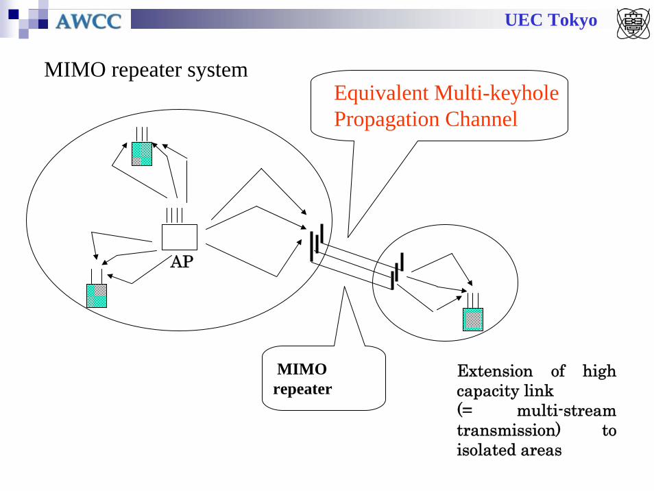
MIMOrepeater
AP
MIMO repeater system
Extension of high capacity link (= multi-stream transmission) to isolated areas
Equivalent Multi-keyholePropagation Channel

UEC Tokyo
Keyhole environment
Multi-keyhole environmentMulti-antenna relay
Single-antenna relayM x 1 x N
M x K x N

UEC Tokyo
M K N
1
2
3
1
2
3
1
K
1
( ) rvrptr nnsHGHr ++=
tre KHHH 1
=
s Ht nrpHr nrv
r
Received signal
Eqivalent channel (CSI)when the effect of thermal noise powerin RS is negligible.
Channel Expression of Radio-Relay Systems
HeeHHR ≡
Hereafter, we discussPDFs of eigenvaluesfor
Accesspoint
Userterminal
UEC Tokyo
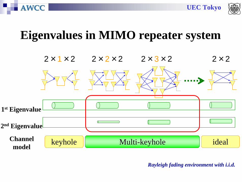
Eigenvalues in MIMO repeater system
2×1×2 2×2×2 2×3×2
1st Eigenvalue
2nd Eigenvalue
2×2
keyhole Multi-keyhole idealChannel model
Rayleigh fading environment with i.i.d.

UEC Tokyo
PDF of the largest eigenvaluein single keyhole environment
( )
( ) ( ) ( )1
121
120 21
22
1)(
λλ
λλ
NM
MN
MN
KMN
duu
pupu
p
−
−+
∞
ΓΓ=
⎟⎠⎞
⎜⎝⎛= ∫
[ ] [ ]tM
ttTrN
rr
tre
hhhhhh 1121112111 LL=
= HHH
)(1HeeTrace HH=λM N1
Ht Hr
Channel response matrix
The p.d.f. of eigenvaluecentral chi-square
distributed with 2Ndegrees of freedom
central chi-square distributed with 2Mdegrees of freedom
(Kv: v-th order modified Bessel function of the second kind)
p2N
p2M
UEC Tokyo
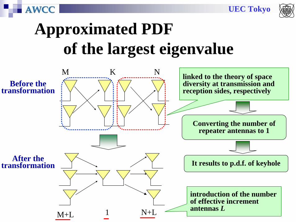
Approximated PDF of the largest eigenvalue
M+L N+L1
Before the transformation
After the transformation
linked to the theory of space diversity at transmission and reception sides, respectively
Converting the number of repeater antennas to 1
introduction of the number of effective increment antennas L
It results to p.d.f. of keyhole
M NK

UEC Tokyo
Introduction of the number of effective increment antennas L
( ) ( )( )βα 1,, −= KNMKNML6681.0,4343.0 == βα
the number of effective increment antennas L
M NK
Before the transformation
M+L N+L1
After the transformation
It is the resonable approximation.
100
101
100 101 102 103
2X2 3X3 4X4 5X5 6X6 近似式
L(M,N,K)
M(K-1)N
Approximation

UEC Tokyo
Approximation equation of p.d.f. of largest eigenvalue for MxKxN case
( ) ( ) ⎟⎟⎠
⎞⎜⎜⎝
⎛
Λ+Γ+ΛΓ
⎟⎠⎞
⎜⎝⎛Λ= −
−++
1
12
2
1
1 22
)( λλ
λ NM
LMN
KLMLN
p
Λ: Power adjustment factor (average value of eigenvalue)

UEC Tokyo
Comparison between simulated values and calculated values ~the largest eigenvalue~
0.001
0.01
0.1
1
0.1 1 10
Cumulativ
e pro
babilit
y
Eigenvalue
N,M=2
N,M=3
K=2K=3K=4
The number K of repeater antennas
K=2K=3K=4
Simulation
Approximation
0.001
0.01
0.1
1
0.1 1 10 100
Cumulative probability
Eigenvalue
N=2,M=4
The number K of repeater antennasSimulation
K=2K=3K=4K=5
K=2K=3K=4K=5
Approximation

UEC Tokyo
PDF of each Eigenvalue in i.i.d. Environment (approximated)
M N
Gamma distributionwith diversity order of
λ1: : M x N
λ2: : (M-1) x (N-1)
λ3: : (M-2) x (N-2)
M x N
(Nt-1) x (Nr-1)
(Nt-2) x (Nr-2)
UEC Tokyo
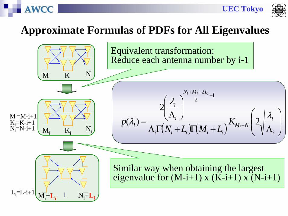
Approximate Formulas of PDFs for All Eigenvalues
M NK
Mi+Li Ni+Li1
MiNiKi
Mi=M-i+1Ki=K-i+1Ni=N-i+1
Li=L-i+1
Similar way when obtaining the largest eigenvalue for (M-i+1) x (K-i+1) x (N-i+1)
Equivalent transformation: Reduce each antenna number by i-1
( ) ( ) ⎟⎟⎠
⎞⎜⎜⎝
⎛
Λ+Γ+ΓΛ
⎟⎟⎠
⎞⎜⎜⎝
⎛Λ
= −
−++
i
iNM
iiiii
LMN
i
i
i ii
iii
KLMLN
p λλ
λ 22
)(
12
2
UEC Tokyo
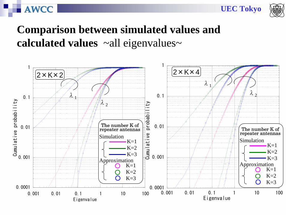
Comparison between simulated values and calculated values ~all eigenvalues~
0.0001
0.001
0.01
0.1
1
0.001 0.01 0.1 1 10 100
Cumulative probability
Eigenvalue
K=1K=2K=3
The number K of repeater antennas
K=1K=2K=3
Simulation
Approximation
λ1λ2
0.0001
0.001
0.01
0.1
1
0.001 0.01 0.1 1 10 100
Cumulative probability
Eigenvalue
K=1K=2K=3
The number K of repeater antennas
K=1K=2K=3
Simulation
Approximation
2×K×2 2×K×4λ1
λ2
UEC Tokyo
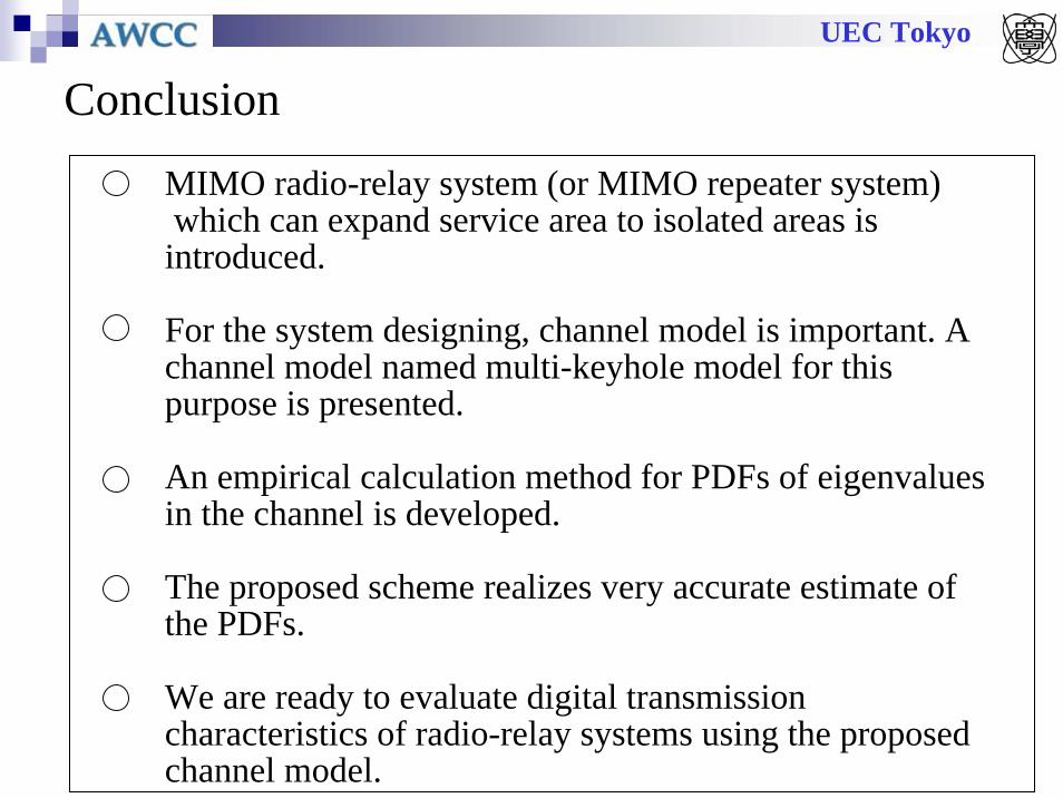
Conclusion
MIMO radio-relay system (or MIMO repeater system) which can expand service area to isolated areas is introduced.
For the system designing, channel model is important. A channel model named multi-keyhole model for this purpose is presented.
An empirical calculation method for PDFs of eigenvaluesin the channel is developed.
The proposed scheme realizes very accurate estimate of the PDFs.
We are ready to evaluate digital transmission characteristics of radio-relay systems using the proposed channel model.