multi-function display mfd-titan
TRANSCRIPT

Operating Instructions
Multi-Function DisplayMFD-Titan
11/10 MN05002001Z-EN

All brand and product names are trademarks or registe-red trademarks of the owner concerned.
Emergency On Call Service Please call your local representative:
http://www.eaton.eu/aftersales or Hotline of the After Sales Service: +49 (0) 180 5 223822 (de, en) [email protected]
Original Operating InstructionsThe German-language edition of this document is the original operating manual.
Translation of the original operating manualAll editions of this document other than those in Ger-man language are translations of the original German manual.
1st published 2003, edition date 06/03,2nd edition 06/04,3rd edition 05/10,4th edition 11/10See revision protocol in the “About this manual“ chapter
© 2003 by Eaton Industries GmbH, 53105 Bonn
Production: DHWTranslation: globaldocs GmbH
All rights reserved, including those of the translation.
No part of this manual may be reproduced in any form (printed, photocopy, microfilm or any other process) orprocessed, duplicated or distributed by means of electronic systems without written permission of Eaton Industries GmbH, Bonn.
Subject to alteration without notice.
Rü
cken
bre
ite
fest
leg
en!
(1 B
latt
=0,
106
mm
, gilt
nu
r fü
r X
BS)
(1 B
latt
=0,
080
mm
fü
r Eb
erw
ein
Dig
ital
dru
ck b
ei 8
0 g
/m2 )

Moe
llerG
mbH
Safe
ty in
stru
ctio
nsDanger!Dangerous electrical voltage!
I
Before commencing the installation
• Disconnect the power supply of the device.
• Ensure that devices cannot be accidentally restarted.
• Verify isolation from the supply.
• Earth and short circuit.
• Cover or enclose neighbouring units that are live.
• Follow the engineering instructions (AWA) of the device concerned.
• Only suitably qualified personnel in accordance with EN 50110-1/-2 (VDE 0105 Part 100) may work on this device/system.
• Before installation and before touching the device ensure that you are free of electrostatic charge.
• The functional earth (FE) must be connected to the protective earth (PE) or to the potential equalisation. The system installer is responsible for implementing this connection.
• Connecting cables and signal lines should be installed so that inductive or capacitive interference does not impair the automation functions.
• Install automation devices and related operating elements in such a way that they are well protected against unintentional operation.
• Suitable safety hardware and software measures should be implemented for the I/O interface so that a line or wire breakage on the signal side does not result in undefined states in the automation devices.
• Ensure a reliable electrical isolation of the low voltage for the 24 volt supply. Only use power supply units complying with IEC 60364-4-41 (VDE 0100 Part 410) or HD 384.4.41 S2.
• Deviations of the mains voltage from the rated value must not exceed the tolerance limits given in the specifications, otherwise this may cause malfunction and dangerous operation.
• Emergency stop devices complying with IEC/EN 60204-1 must be effective in all operating modes of the automation devices. Unlatching the emergency-stop devices must not cause restart.
• Devices that are designed for mounting in housings or control cabinets must only be operated and controlled after they have been installed with the housing closed. Desktop or portable units must only be operated and controlled in enclosed housings.
• Measures should be taken to ensure the proper restart of programs interrupted after a voltage dip or failure. This should not cause dangerous operating states even for a short time. If necessary, emergency-stop devices should be implemented.
• Wherever faults in the automation system may cause damage to persons or property, external measures must be implemented to ensure a safe operating state in the event of a fault or malfunction (for example, by means of separate limit switches, mechanical interlocks etc.).

II

Handbuch 11/10 MN05002001Z-DE www.eaton.com 1
Contents
0 About This Manual..................................................................... 13
0.1 List of revisions ............................................................................ 13
0.2 Target group................................................................................. 14
0.3 Exclusion of liability ...................................................................... 14
0.4 Device designation....................................................................... 16
0.5 Writing conventions ..................................................................... 17
1 MFD ............................................................................................. 19
1.1 Proper use.................................................................................... 19
1.2 Overview of functions.................................................................. 19
1.3 Versions ....................................................................................... 211.3.1 Display and operating unit............................................................ 211.3.2 Power supply/CPU module .......................................................... 211.3.3 I/O module digital/analog.............................................................. 221.3.4 I/O module with temperature measuring..................................... 221.3.5 LED display .................................................................................. 231.3.6 Key to part numbers MFD............................................................ 24
1.4 Possible combinations of basic devices and expansion units ...... 24
1.5 Extended functionality of MFD-CP10... compared to MFD-CP8... ........................................................................................... 27
1.6 MFD operation ............................................................................. 281.6.1 Key Pad ........................................................................................ 281.6.2 Selecting menus and entering values .......................................... 281.6.3 Status display for the MFD basic device...................................... 291.6.4 Status display for the local expansion module ............................. 311.6.5 Status display additional information............................................ 311.6.6 Menu structure ............................................................................ 321.6.7 Choosing the main and system menu ......................................... 321.6.8 Main menu without activated password protection..................... 331.6.9 Main menu with activated password protection.......................... 331.6.10 System menu............................................................................... 341.6.11 Selecting or toggling between menu items ................................. 361.6.12 Cursor display............................................................................... 361.6.13 Setting values............................................................................... 37

2 Handbuch 11/10 MN05002001Z-DE www.eaton.com
2 Installation.................................................................................. 39
2.1 Mounting the MFD ...................................................................... 402.1.1 Fitting the protective diaphragm/cover on the MFD-80............... 422.1.2 Front mounting of the MFD-80 display/HMI unit ......................... 452.1.3 Connecting the power supply/CPU to the display/HMI unit ........ 472.1.4 Connecting the input/output module to the power supply unit/
CPU module................................................................................. 482.1.5 Mounting the MFD-CP8/CP10 on a top-hat rail............................ 502.1.6 Screwing on the MFD-CP8/CP10................................................. 53
2.2 Mounting the expansion unit ....................................................... 542.2.1 Local expansion module .............................................................. 552.2.2 Remote expansion....................................................................... 56
2.3 Terminations ................................................................................ 572.3.1 Tools ............................................................................................ 572.3.2 Cable cross-sections.................................................................... 57
2.4 Connecting the power supply ...................................................... 572.4.1 Cable protection........................................................................... 572.4.2 MFD-AC... power supply unit/CPU module ................................. 582.4.3 AC expansion unit EASY618-AC-RE............................................. 582.4.4 MFD-... DC power supply/CPU module ....................................... 592.4.5 DC expansion unit EASY…-DC-.E ................................................ 59
2.5 Connecting inputs ........................................................................ 602.5.1 Connect digital AC inputs............................................................. 612.5.2 Connecting easy DC digital inputs ............................................... 652.5.3 Connecting analog inputs............................................................. 69
2.6 Connecting outputs...................................................................... 752.6.1 Connecting relay outputs ............................................................. 762.6.2 Connecting digital transistor outputs ........................................... 782.6.3 Connecting analog outputs .......................................................... 80
2.7 Connecting the NET network................................................ 822.7.1 Connection assignment of the RJ45 socket on the device ......... 822.7.2 Bus termination resistor............................................................... 832.7.3 Pre-assembled Net connection cables.................................. 842.7.4 User-assembled Net connection cables ............................... 842.7.5 Fitting and removing Net connection cables......................... 842.7.6 Net-topologies....................................................................... 852.7.7 Cable length with cross-sections ................................................. 87
2.8 Connecting the serial multi-function interface ............................. 882.8.1 Connection to a PC ...................................................................... 892.8.2 Connecting for point-to-point communication.............................. 912.8.3 Inserting the memory card........................................................... 93

Handbuch 11/10 MN05002001Z-DE www.eaton.com 3
3 Commissioning .......................................................................... 95
3.1 Switch-on ..................................................................................... 95
3.2 Setting the menu language .......................................................... 95
3.3 Operating modes ......................................................................... 963.3.1 RUN, STOP, TERMINAL MODE and BUSY ................................. 96
3.4 The first circuit diagram................................................................ 983.4.1 Starting point: the status display.................................................. 983.4.2 Switching to the circuit diagram................................................... 993.4.3 Draw a wiring diagram ................................................................ 1003.4.4 Testing the circuit diagram........................................................... 1043.4.5 Deleting the circuit diagram ......................................................... 106
3.5 I/O module with temperature measuring..................................... 1073.5.1 Properties of the temperature modules....................................... 1073.5.2 Menu PARAMETERS ................................................................... 1083.5.3 Menu DIAGNOSTICS ................................................................... 1163.5.4 Menu INFORMATION.................................................................. 1163.5.5 NEW PARAMETERS...!................................................................ 117
3.6 Configuring the analog expansion unit ......................................... 1173.6.1 Setting device parameters (IO-DEVICE menu)............................ 1183.6.2 Processing analog input/output values......................................... 1203.6.3 Diagnostics of an analog expansion unit ...................................... 122
3.7 When controlling a contactor or relay, the control coil is only present once.Commissioning NET stations ................................. 122
3.7.1 NET parameterize......................................................................... 1233.7.2 Configuring NET ........................................................................... 1273.7.3 Changing the NET configuration .................................................. 1293.7.4 Showing the status display of other NET stations ....................... 131
3.8 COM-LINK connection ................................................................. 1323.8.1 General information on COM-LINK ............................................. 1323.8.2 Configuring the interface for COM-LINK...................................... 133
3.9 Running MFD in Terminal mode .................................................. 1363.9.1 MFD as a station of a point-to-point connection .......................... 1373.9.2 MFD as NET station ..................................................................... 138

4 Handbuch 11/10 MN05002001Z-DE www.eaton.com
4 Wiring with MFD........................................................................ 145
4.1 MFD operation............................................................................. 1454.1.1 Pushbutton for editing circuit diagrams and function blocks ....... 1454.1.2 Operation ..................................................................................... 145
4.2 Circuit diagram elements............................................................. 1464.2.1 Program ....................................................................................... 1464.2.2 Function blocks............................................................................ 1464.2.3 Visualization screens.................................................................... 1464.2.4 Relays .......................................................................................... 1474.2.5 Contacts and coils of the circuit diagram..................................... 1474.2.6 Markers and analog operands...................................................... 152
4.3 Circuit diagram display ................................................................. 157
4.4 Program transfer from and to the memory card .......................... 1584.4.1 Information on the memory card ................................................. 1584.4.2 Transfer from/to a device without display or keypad................... 1594.4.3 Compatibility of program and MFD device .................................. 1594.4.4 Loading and saving with a memory card ..................................... 161
4.5 Deleting a program on the card ................................................... 164
4.6 Loading and saving with Soft-Pro ......................................... 164
4.7 Working with contacts and relays................................................ 1654.7.1 Entering and changing contacts and coils.................................... 1664.7.2 Creating or changing connections ............................................... 1694.7.3 Adding or deleting rungs.............................................................. 1704.7.4 Saving circuit diagrams ................................................................ 1704.7.5 Aborting circuit diagram entry...................................................... 1704.7.6 Searching for contacts and coils .................................................. 1714.7.7 Got to a rung................................................................................ 1714.7.8 Delete Rung................................................................................. 1714.7.9 Switching with the Cursor Buttons.............................................. 1724.7.10 Coil Functions .............................................................................. 1744.7.11 Jumps .......................................................................................... 1774.7.12 Wiring NET operands in the circuit diagram................................. 1794.7.13 Read and write of NET operands................................................. 1804.7.14 NET operands nRN.. (input) and nSN.. (output) ........................... 1814.7.15 SN-RN example............................................................................ 1834.7.16 NET operand GT.. (receive), PT.. (send) and SC.. (set date and
time)............................................................................................. 184
4.8 Wiring COM-LINK operands in the circuit diagram...................... 1844.8.1 Operand access in the active MFD.............................................. 1844.8.2 Access method............................................................................ 187
4.9 Working with function blocks ...................................................... 1884.9.1 Adding function blocks to the circuit diagram for the first time... 1894.9.2 Setting function block parameters ............................................... 1894.9.3 Changing function block parameters ........................................... 1944.9.4 Deleting function blocks .............................................................. 1964.9.5 Checking function blocks............................................................. 196

Handbuch 11/10 MN05002001Z-DE www.eaton.com 5
5 Function blocks .......................................................................... 199
5.1 A, analog value comparator/threshold value switch..................... 1995.1.1 Function block inputs/outputs ...................................................... 1995.1.2 Wiring of the function block ......................................................... 2005.1.3 Contacts ....................................................................................... 2005.1.4 Parametric programming of the function block inputs/outputs.... 2005.1.5 Function of the function block...................................................... 202
5.2 AR, Arithmetic.............................................................................. 2045.2.1 Function block inputs/outputs ...................................................... 2045.2.2 Wiring of the function block ......................................................... 2045.2.3 Parametric programming of the function block inputs/outputs.... 2055.2.4 Function of the function block...................................................... 206
5.3 BC, data block comparator ........................................................... 2085.3.1 Function block inputs/outputs ...................................................... 2085.3.2 Wiring of the function block ......................................................... 2085.3.3 Parametric programming of the function block inputs/outputs.... 2095.3.4 Function of the function block...................................................... 211
5.4 BT, Data block Transformer ......................................................... 2165.4.1 Function block inputs/outputs ...................................................... 2165.4.2 Wiring of the function block ......................................................... 2165.4.3 Parametric programming of the function block inputs/outputs.... 2175.4.4 Function of the function block...................................................... 220
5.5 BV, Boolean operation.................................................................. 2285.5.1 Function block inputs/outputs ...................................................... 2285.5.2 Wiring of the function block ......................................................... 2285.5.3 Parametric programming of the function block inputs/outputs.... 2295.5.4 Function of the function block...................................................... 230
5.6 C, counter relay ............................................................................ 2325.6.1 Function block inputs/outputs ...................................................... 2325.6.2 Wiring of the function block ......................................................... 2335.6.3 Parametric programming of the function block inputs/outputs.... 2345.6.4 Function of the function block...................................................... 236
5.7 CF, frequency counter.................................................................. 2385.7.1 Function block inputs/outputs ...................................................... 2385.7.2 Wiring of the function block ......................................................... 2395.7.3 Parametric programming of the function block inputs/outputs.... 2405.7.4 Function of the function block...................................................... 242
5.8 CH, high-speed counter ............................................................... 2435.8.1 Function block inputs/outputs ...................................................... 2435.8.2 Wiring of the function block ......................................................... 2445.8.3 Parametric programming of the function block inputs/outputs.... 2455.8.4 Function of the function block...................................................... 247
5.9 CI, High-speed incremental value counter ................................... 2495.9.1 Function block inputs/outputs ...................................................... 2495.9.2 Wiring of the function block ......................................................... 2505.9.3 Parametric programming of the function block inputs/outputs.... 2515.9.4 Function of the function block...................................................... 253

6 Handbuch 11/10 MN05002001Z-DE www.eaton.com
5.10 CP, comparator ............................................................................ 2555.10.1 Function block inputs/outputs...................................................... 2555.10.2 Wiring of the function block......................................................... 2555.10.3 Parametric programming of the function block inputs/outputs.... 2565.10.4 Function of the function block ..................................................... 257
5.11 DB, data block.............................................................................. 2585.11.1 Function block inputs/outputs...................................................... 2585.11.2 Wiring of the function block......................................................... 2585.11.3 Parametric programming of the function block inputs/outputs.... 2595.11.4 Function of the function block ..................................................... 260
5.12 DC, PID controller ........................................................................ 2615.12.1 Function block inputs/outputs...................................................... 2625.12.2 Wiring of the function block......................................................... 2625.12.3 Parametric programming of the function block inputs/outputs.... 2635.12.4 Function of the function block ..................................................... 266
5.13 FT, signal smoothing filter............................................................ 2685.13.1 Function block inputs/outputs...................................................... 2685.13.2 Wiring of the function block......................................................... 2695.13.3 Parametric programming of the function block inputs/outputs.... 2695.13.4 Function of the function block ..................................................... 271
5.14 GT, get value from the NET ......................................................... 2735.14.1 Function block inputs/outputs...................................................... 2735.14.2 Wiring of the function block......................................................... 2735.14.3 Parametric programming of the function block inputs/outputs.... 2745.14.4 Function of the function block ..................................................... 275
5.15 HW, weekly timer ........................................................................ 2765.15.1 Function block inputs/outputs...................................................... 2765.15.2 Function ....................................................................................... 2765.15.3 Behavior in the event of a power failure ...................................... 2765.15.4 Wiring of the function block......................................................... 2775.15.5 Parametric programming of the function block inputs/outputs.... 2775.15.6 Operation of the function block ................................................... 279
5.16 HY - Year Time Switch................................................................. 2825.16.1 Function ....................................................................................... 2825.16.2 Behavior in the event of a power failure ...................................... 2835.16.3 Wiring of the function block......................................................... 2835.16.4 Parametric programming of the function block inputs/outputs.... 2835.16.5 How the function block works..................................................... 2855.16.6 Entry rules.................................................................................... 2855.16.7 Sample parameter configurations ................................................ 287
5.17 JC, conditional jump..................................................................... 2915.17.1 Function block inputs/outputs...................................................... 2915.17.2 Wiring of the function block......................................................... 2915.17.3 Parametric programming of the function block inputs/outputs.... 2925.17.4 Function of the function block ..................................................... 292
5.18 LB, jump label .............................................................................. 294
5.19 LS, value scaling .......................................................................... 295
Handbuch 11/10 MN05002001Z-DE www.eaton.com 7
5.19.1 Function block inputs/outputs ...................................................... 2955.19.2 Wiring of the function block ......................................................... 2955.19.3 Parametric programming of the function block inputs/outputs.... 2965.19.4 Function of the function block...................................................... 2975.19.5 Application example ..................................................................... 299
5.20 MR, master reset ......................................................................... 3005.20.1 Function block inputs/outputs ...................................................... 3005.20.2 Wiring of the function block ......................................................... 3005.20.3 Parametric programming of the function block inputs/outputs.... 3015.20.4 Function of the function block...................................................... 302
5.21 MX, data multiplexer .................................................................... 3035.21.1 Function block inputs/outputs ...................................................... 3035.21.2 Wiring of the function block ......................................................... 3035.21.3 Parametric programming of the function block inputs/outputs.... 3045.21.4 Function of the function block...................................................... 305
5.22 NC, numerical converter .............................................................. 3075.22.1 Function block inputs/outputs ...................................................... 3075.22.2 Wiring of the function block ......................................................... 3075.22.3 Parametric programming of the function block inputs/outputs.... 3085.22.4 Function of the function block...................................................... 310
5.23 OT, operating hours counter ........................................................ 3125.23.1 Function block inputs/outputs ...................................................... 3125.23.2 Wiring of the function block ......................................................... 3125.23.3 Parametric programming of the function block inputs/outputs.... 3135.23.4 Function of the function block...................................................... 314
5.24 PT - Put value to the NET ............................................................. 3155.24.1 Function block inputs/outputs ...................................................... 3155.24.2 Wiring of the function block ......................................................... 3155.24.3 Parametric programming of the function block inputs/outputs.... 3165.24.4 Function of the function block...................................................... 318
5.25 PW, pulse width modulation ........................................................ 3195.25.1 Function block inputs/outputs ...................................................... 3195.25.2 Wiring of the function block ......................................................... 3195.25.3 Parametric programming of the function block inputs/outputs.... 3205.25.4 Function of the function block...................................................... 322
5.26 SC, set date/time ......................................................................... 3235.26.1 Function block inputs/outputs ...................................................... 3235.26.2 Wiring of the function block ......................................................... 3235.26.3 Parametric programming of the function block inputs/outputs.... 3245.26.4 Function of the function block...................................................... 324
5.27 SR, shift register .......................................................................... 3255.27.1 Function block inputs/outputs ...................................................... 3255.27.2 Wiring of the function block ......................................................... 3265.27.3 Parametric programming of the function block inputs/outputs.... 3285.27.4 Function of the function block...................................................... 330
5.28 ST, Set cycle time ........................................................................ 3375.28.1 Function block inputs/outputs ...................................................... 337

8 Handbuch 11/10 MN05002001Z-DE www.eaton.com
5.28.2 Wiring of the function block......................................................... 3375.28.3 Parametric programming of the function block inputs/outputs.... 3375.28.4 Function of the function block ..................................................... 339
5.29 T, timing relay .............................................................................. 3405.29.1 Function block inputs/outputs...................................................... 3405.29.2 Wiring of the function block......................................................... 3405.29.3 Parametric programming of the function block inputs/outputs.... 3415.29.4 Function of the function block ..................................................... 344
5.30 TB, table function......................................................................... 3505.30.1 Function block inputs/outputs...................................................... 3505.30.2 Wiring of the function block......................................................... 3505.30.3 Parametric programming of the function block inputs/outputs.... 3525.30.4 Function of the function block ..................................................... 353
5.31 VC, value limitation ...................................................................... 3555.31.1 Function block inputs/outputs...................................................... 3555.31.2 Wiring of the function block......................................................... 3555.31.3 Parametric programming of the function block inputs/outputs.... 3565.31.4 Function of the function block ..................................................... 357
5.32 Example with timing relay and counter function block ................ 358
6 Visualization with MFD-Titan................................................... 361
6.1 Screens........................................................................................ 3616.1.1 Exchangeability of MFD-CP8...- and MFD-CP10... screens ......... 3626.1.2 Exchangeability of MFD-CP8...- and MFD-CP10... screen
elements...................................................................................... 3626.1.3 Exchangeability of MFD-CP8...- and MFD-CP10... languages...... 3626.1.4 Exchangeability of MFD-CP8...- and MFD-CP10... passwords..... 3626.1.5 Replacing an MFD-CP8...- with an MFD-CP10............................. 362
6.2 User interface Soft-Pro ......................................................... 3636.2.1 Visualization View ........................................................................ 3636.2.2 Simulation View ........................................................................... 3646.2.3 Communication View................................................................... 364
6.3 Screen Overview ......................................................................... 3656.3.1 Register "Screens"........................................................................ 3656.3.2 Register „Passwords“................................................................. 3666.3.3 Register „Languages“ ................................................................. 3666.3.4 Register „Screen Activation“....................................................... 3676.3.5 Current screen tab ....................................................................... 369
6.4 Screen Editor ............................................................................... 3696.4.1 Screen memory ........................................................................... 3706.4.2 Creating masks ............................................................................ 3716.4.3 Static Text .................................................................................... 3736.4.4 Message Text .............................................................................. 3756.4.5 Screen Menu ............................................................................... 3826.4.6 Running Text................................................................................ 3836.4.7 Rolling Text .................................................................................. 3846.4.8 Latching pushbutton .................................................................... 3856.4.9 Button Field ................................................................................. 386

Handbuch 11/10 MN05002001Z-DE www.eaton.com 9
6.4.10 Bit Display .................................................................................... 3886.4.11 Bitmap.......................................................................................... 3916.4.12 Message Bitmap .......................................................................... 3956.4.13 Bar Graph ..................................................................................... 3966.4.14 Date and Time Display ................................................................. 3986.4.15 Numerical value............................................................................ 4006.4.16 Timing Relay Value Display .......................................................... 4056.4.17 Value Entry ................................................................................... 4066.4.18 Timing relay value entry ............................................................... 4116.4.19 Date and time entry ..................................................................... 4126.4.20 Weekly timer inputs ..................................................................... 4136.4.21 Year time switch entry ................................................................. 414
6.5 Button operation on the MFD-Titan ............................................. 4166.5.1 Operating principle in the visualization......................................... 416
6.6 Button Editor ................................................................................ 4176.6.1 How to Assign a Pushbutton Element to a Pushbutton............... 4186.6.2 Select operable screen element .................................................. 4196.6.3 Display Backlight .......................................................................... 4196.6.4 Display contrast............................................................................ 4206.6.5 Screen change ............................................................................. 4206.6.6 Password logout .......................................................................... 4216.6.7 Set variable to fixed value ............................................................ 4226.6.8 Decrement Variable...................................................................... 4236.6.9 Increment Variable ....................................................................... 4246.6.10 Changeover relay ......................................................................... 4266.6.11 Disable Change to Status Display ................................................ 4266.6.12 P button function.......................................................................... 4276.6.13 Go To Previous Screen................................................................. 4286.6.14 Disable Selection Mode ............................................................... 4296.6.15 Jump Label................................................................................... 4296.6.16 Conditional Jump ......................................................................... 430
6.7 Password Protecting Screens ...................................................... 4326.7.1 Configure password ..................................................................... 4326.7.2 Language adaption of the title text "PASSWORD ENTRY:".......... 4326.7.3 Logout Time ................................................................................. 4336.7.4 Password entry in run .................................................................. 4346.7.5 Schematic procedure for password entry by the operator........... 435

10 Handbuch 11/10 MN05002001Z-DE www.eaton.com
7 The network Net................................................................. 437
7.1 Introduction network Net...................................................... 4377.1.1 Transfer behavior of the NET stations ......................................... 4387.1.2 Functions of the NET stations...................................................... 4397.1.3 Function "terminal mode" ............................................................. 439
7.2 Description of the NET-PARAMETERs ........................................ 4407.2.1 Station number (Station Menu NET-ID) ....................................... 4407.2.2 Data transfer speed (Station Menu BAUD RATE)........................ 4407.2.3 Pause time, changing the write repetition rate manually
(Station Menu BUSDELAY).......................................................... 4417.2.4 Send each change on the inputs/outputs (Station Menu SEND
IO) ................................................................................................ 4427.2.5 Automatic change of the RUN and STOP mode (Station Menu
REMOTE RUN) ............................................................................ 4437.2.6 Configuring an input/output device without its own circuit
diagram REMOTE IO menu item) ................................................ 443
7.3 Network transmission security .................................................... 444
8 MFD Settings.............................................................................. 445
8.1 Safety........................................................................................... 4458.1.1 Password protection.................................................................... 4458.1.2 Inputting a password ................................................................... 4458.1.3 Activating Passwords................................................................... 4478.1.4 Unlocking MFD ........................................................................... 4488.1.5 Changing passwords.................................................................... 4488.1.6 Delete password.......................................................................... 4498.1.7 Password no longer known or incorrect ...................................... 449
8.2 System......................................................................................... 4508.2.1 Switching on the input delay function (Debounce menu) ............ 4508.2.2 P PUSHBUTTONS........................................................................ 4518.2.3 Setting the startup behavior......................................................... 4528.2.4 TERMINAL MODE startup (TERMINAL MODE menu item) ....... 4548.2.5 Activating external buttons (I-BUTTONS and R-BUTTONS
menu items)................................................................................. 4558.2.6 Setting contrast and backlight (DISPLAY menu item).................. 4568.2.7 Storing data retentively (Retention menu item...) ....................... 458
8.3 Menu language ............................................................................ 4618.3.1 Changing the menu language ...................................................... 461
8.4 Configurator ................................................................................. 4628.4.1 NET .............................................................................................. 4628.4.2 COM ............................................................................................ 4628.4.3 LINK ............................................................................................. 4638.4.4 Configuring analog expansion units ............................................. 4638.4.5 Configure communication expansion unit.................................... 4638.4.6 ETHERNET-GW............................................................................ 463

Handbuch 11/10 MN05002001Z-DE www.eaton.com 11
8.4.7 IO MODULES............................................................................... 464
8.5 Setting time.................................................................................. 4648.5.1 Setting time and date................................................................... 4648.5.2 Summer/winter time .................................................................... 464
9 Inside MFD.................................................................................. 469
9.1 MFD Program............................................................................... 4699.1.1 How the MFD device evaluates circuit diagrams and function
blocks ........................................................................................... 4699.1.2 Cycle-time monitoring .................................................................. 4709.1.3 What you must consider when creating the circuit diagram........ 4719.1.4 Allowing for the special feature of certain function blocks .......... 4729.1.5 What affects the cycle time of an MFD device............................ 4729.1.6 MFD memory management......................................................... 473
9.2 Time behavior of the inputs and outputs ..................................... 4749.2.1 Input delay (debounce)................................................................. 4749.2.2 Delay time with MFD DC basic devices....................................... 4759.2.3 Delay time with MFD AC basic devices....................................... 476
9.3 Diagnostics................................................................................... 4799.3.1 Diagnostics using the ID diagnostics contact .............................. 4799.3.2 Checking the transistor output for short-circuit/overload ............. 480
9.4 Expanding an MFD device ........................................................... 4819.4.1 How is an expansion unit detected? ............................................ 4829.4.2 Link transfer behavior............................................................ 4829.4.3 Monitoring the functionality of the expansion unit....................... 482
9.5 Monitoring the serial multi-function interface .............................. 483
9.6 Monitoring the COM-LINK connection......................................... 483
9.7 Displaying device information ...................................................... 484
9.8 Device Version Number ............................................................... 485
10 What Happens If …? .................................................................. 487
10.1 Messages from the MFD operating system ................................ 487
10.2 Possible situations when creating circuit diagrams ..................... 488
10.3 Event ............................................................................................ 489
10.4 Functionality of the NET faulty ..................................................... 48910.4.1 Monitoring via diagnostics bits..................................................... 490
10.5 Replacing a NET station ............................................................... 491
10.6 Power supply failure on station with NET-ID 1 ............................ 492

12 Handbuch 11/10 MN05002001Z-DE www.eaton.com
11 Appendix..................................................................................... 493
11.1 Approval and Certification ............................................................ 49311.1.1 Approvals and national approvals for MFD devices ..................... 49311.1.2 Shipping approvals for MFD devices .......................................... 49311.1.3 Approvals and national approvals for expansion devices ............. 49411.1.4 Shipping approvals for 6.. expansion devices ....................... 494
11.2 Dimensions.................................................................................. 49511.2.1 MFD-80.. display/operator unit..................................................... 49511.2.2 Power supply unit/CPU MFD-CP8…............................................ 49611.2.3 Input/output modules MFD-R.. , MFD-T.. .................................... 49711.2.4 MFD-80-XM protective diaphragm............................................... 49711.2.5 MFD-80-XS protective cover........................................................ 498
11.3 Technical data .............................................................................. 49911.3.1 Standards..................................................................................... 49911.3.2 General ambient conditions ......................................................... 49911.3.3 Display/operating unit .................................................................. 50111.3.4 Power supply ............................................................................... 50211.3.5 Central processing unit, real-time clock/timing relay/memory ..... 50311.3.6 Inputs........................................................................................... 50511.3.7 Analog output .............................................................................. 51411.3.8 NET network ......................................................................... 515
11.4 List of function blocks.................................................................. 51611.4.1 Function block coils...................................................................... 51711.4.2 Function block contacts ............................................................... 51811.4.3 Function block inputs (constants, operands)................................ 51911.4.4 Function block output (operands)................................................. 52011.4.5 Other operands............................................................................ 520
11.5 Memory requirement................................................................... 520
11.6 Basic and extended Western European character set................. 522
11.7 Central European expansion character set .................................. 524
11.8 Cyrillic expansion character set.................................................... 525
Index ........................................................................................... 527

0 About This Manual
0.1 List of revisions
Manual 11/10 MN05002001Z-EN www.eaton.com 13
0 About This Manual
This manual describes the installation, commissioning and programming (circuit diagram creation) of the MFD combined visualization device and control relay.
Specialist electrical training is needed for commissioning and creating circuit diagrams.
The latest edition of this manual can be obtained from the Download
Center - Documentation at: Eaton.eu,/doc
0.1 List of revisionsThis edition was fully revised. The following table therefore only lists major modifications.
DANGER
If active components are controlled, such as motors or pressurized cylinders, plant plants may become damaged or persons endangered, provided MFD is incorrectly connected, or incorrectly configured and programmed.
Publication date
Page Key word New Change omitted
11/10
161 Double sized memory card for MFD-CP10...
303 "Multiplexer" function block, MX for MFD-CP10...
361 Program examples for screen elements
366 16 download languages on MFD-CP10...
453 CARD MODE
458 Increased memory on MFD-CP10... for retentive data
473 Increased program and screen memory on MFD-CP10.. .
417 "Display contrast" button element for MFD-CP10...
427 P button function possible on all operator buttons of the MFD-CP10...
458 Increased retentive range on MFD-CP10.. .

0 About This Manual
0.2 Target group
14 Manual 11/10 MN05002001Z-EN www.eaton.com
0.2 Target group
A MFD device may only be fitted and connected by a qualified electrician or a person who is familiar with electrical installations.
0.3 Exclusion of liabilityAll information in this manual was provided by us to the best of our knowledge and belief and in accordance with the current state-of-the-art. However, inaccuracies cannot be totally excluded, and we therefore do not assume any liability for the accuracy or completeness of this information. This information in particular does not contain any guarantee for the provision of specific properties.
The devices described must only be installed and operated in accordance with the content of this operator manual and the installation instructions provided with the device. Mounting, commissioning, operation, maintenance and refitting of the devices must only be carried out by qualified persons. The devices must only be used in the areas recommended and only in conjunction with third-party devices and components that have been approved by us. Their use is allowed fundamentally only in technically faultless condition. Fault-free and safe operation of the system requires proper transport, storage, mounting and commissioning as well as careful operation and maintenance.If the following safety instructions are not observed, particularly with regard to commissioning and maintenance of the devices by insufficiently qualified personnel and/or in the event of improper use of the devices, any hazards caused by the devices cannot be excluded. We cannot accept any liability for any resulting injury or damage.
The use of such sample programs and of the easySoft-Pro programming software are subject to the following safety instructions and operating guidelines:
1. The program examples provided were created to the best of our knowledge and belief and in accordance with the current state-of-the-art. However, errors cannot be totally excluded, and the example programs do not cover all function blocks and applications that are available for the easy800-/MFD-CP8.../CP10... devices.
2. A specialist knowledge of electrical engineering is needed for the programming and commissioning of easy800/MFD-CP8.../CP10... devices. Plant sections and persons are at risk if an easy800-/MFD-CP8.../CP10... device is incorrectly connected or configured and active components such as motors or pressure cylinders are controlled.
DANGER
Specialist electrical training is needed for creating circuit diagrams and commissioning. Plant sections and persons are at risk if a MFD device is incorrectly connected or programmed and active components such as motors or pressure cylinders are controlled.

0 About This Manual
0.3 Exclusion of liability
Manual 11/10 MN05002001Z-EN www.eaton.com 15
3. When using the provided sample programs and generating a program with easySoft, the user has the sole responsibility to observe the following:
• All relevant regulations regarding the preparation of a circuit diagram for easy800-/MFD-CP8.../CP10... devices according to the updated user manuals of easy800-/MFD-CP8.../CP10... devices.
• All relevant regulations, directives, rules and standards of occupational safety and accident prevention regarding the intended preparation of circuit diagrams, initial commissioning and the operation of easy800-/MFD-CP8.../CP10... devices, particularly those issued by Employers’ Liability Insurance Associations (Berufsgenossenschaften).
• Acknowledged rule of technology and state of science.• All other general due diligence regarding the prevention of damages to
life and physical condition of persons as well as material damage.
4. The manufacturer cannot accept any liability for any damages that are caused by customers not using the example programs provided in accordance with the conditions of use specified under points 1 to 3.

0 About This Manual
0.4 Device designation
16 Manual 11/10 MN05002001Z-EN www.eaton.com
0.4 Device designation
The following terms are used for the device types if the description applies to all these types:
• easy600 for• EASY618-.C-RE• EASY620-DC-TE
• easy500/700 for• all EASY5..-..-... and • all EASY7..-..-...
• easy800 for• EASY819-…,• EASY820-…,• EASY821-…,• EASY822-…
• MFD-Titan for• all components belonging to the Multi-function display family
consisting of power supply/CPU module (MFD-CP...) or power supply/communication module (MFD-CP4...), display/operator unit (MFD-80...) and I/O module.
• MFD for• the programmable devices (visualization devices), consisting of
power supply/CPU module (MFD-..-MFD fCP8.../CP10...), display/operator unit (MFD-80...) and I/O module.
• MFD-CP8.../CP10... for• the programmable MFD-CP8…, MFD-AC-CP8… and MFD-CP10….
power supply/CPU modules
• MFD-CP8… for• the MFD-CP8… and MFD-AC-CP8… power supply/CPU modules
including the easyNet-compatible modules.
• MFD-CP10… for• the MFD-CP10-ME and the MFD-CP10-NT easyNet-compatible
module.
• MFD-...-NT for• easyNet-compatible power supply/CPU modules
• MFD-CP4… forMFD-CP4… and MFD-AC-CP4… power supply unit/communication modules
• easy-AC for• EASY8..-AC-…• EASY618-AC-RE
• easy-DC for• EASY6…-DC-TE• EASY8…-.DC-…

0 About This Manual
0.5 Writing conventions
Manual 11/10 MN05002001Z-EN www.eaton.com 17
0.5 Writing conventions
Symbols used in this manual have the following meanings:
indicates actions to be taken.
For greater clarity, the name of the current chapter is shown in the 1. headline and the name of the current section in the 2. headline.
CAUTION
Warns about the possibility of material damage.
WARNING
Warns of the possibility of hazardous situations that may possibly cause injury.
WARNING
Warns of the possibility of hazardous situations that could result in serious or even death.
DANGER
Warns of hazardous situations that result in serious injury or death.
→ Draws your attention to interesting tips and supplementary information.

0 About This Manual
0.5 Writing conventions
18 Manual 11/10 MN05002001Z-EN www.eaton.com

1 MFD
1.1 Proper use
Manual 11/10 MN05002001Z-EN www.eaton.com 19
1 MFD
1.1 Proper useAn MFD is a programmable display, operator, switching, closed-loop and open-loop control device that enables the replacement of relay and contactor control circuits as well operator and display units. The device has a modular design and can be used in different combinations:
• Power supply unit/CPU module + Input/output module (I/O module)• Power supply unit/central processing unit + display /operating unit• Power supply unit/central processing unit + display/operating unit + I/O
module
It is also possible to use an expansion unit with all combinations.
The MFD device is a mounted device and must be installed in an enclosure, control cabinet or service distribution board with protection type IP54 or higher.
The display and HMI device is protected to IP65 and normally does not require any special housing protection. The rear-mounted “power supply/CPU module”, “I/O module” and “expansion units” are built-in devices and must be installed in a housing, a switch cabinet or a service distribution board.
Power supply and signal terminals must be protected against accidental contact and covered.
The MFD device may only be operated if it has been correctly fitted and connected by qualified electrical specialists. The installation must comply with regulations for electromagnetic compatibility (EMC).
The MFD device should not be used as a substitute for safety-related controls such as burner controls, emergency-stop or two-hand safety controls.
1.2 Overview of functionsThe MFD is an electronic display and operator unit and control relay. It is equipped with:
• Logic functions• Timing relay and counter functions• Time switch functions• Arithmetic functions
DANGER
The power up of the MFD device must not cause any hazards arising from activated devices, such as unexpected motor startups or power ups.

1 MFD
1.2 Overview of functions
20 Manual 11/10 MN05002001Z-EN www.eaton.com
• PID controllers• Integrated display and operating elements.
With MFD-CP8.../CP10... you can create solutions for domestic applications as well as for tasks in machinery and plant construction. MFD-CP8.../CP10... is a modular and flexible device.
The integrated easyNet network makes it possible to connect up to eight NET stations to a PLC. All devices with a NET terminal connection can be used as NET stations. At present these devices consist of easy800/MFD-CP8.../CP10..., easySafety devices or type XC200/EC4-200 PLCs.
Each Net station can process its own circuit diagram and a visualization application. This allows the design of systems using high-speed controllers with decentralized intelligence.
Each Net station can process its own circuit diagram and a visualization application. This allows the design of systems using high-speed controllers with decentralized intelligence.
With easy you can create a circuit diagram in ladder diagram. The circuit diagram entry can be carried out directly on the device using the operator buttons or on your PC using the easySoft-Pro programming software.
For example, you can:
• Connect N/O and N/C contacts in series and in parallel• Connect output relays and markers.• Define outputs as coils, impulse relays, rising or falling edge-triggered
relays or as latching relays.
The function blocks provide you with several functions such as arithmetic functions, value comparison functions or up/down counting. All function blocks provided are listed in alphabetical order in the Appendix on page 516. The cross-references provide links to detailed descriptions of these function blocks.
If you wish to wire an MFD via your PC, i.e. create a circuit diagram, use the easySoft-Pro programming software.
easySoft-Pro also allows you to:
• test your circuit diagram by simulating the power flow (offline test).• create your visualization device (exclusively with easySoft-Pro),
consisting of screens and their association with the circuit diagram.• transfer a program consisting of circuit diagram and visualization to a
connected and operational MFD-CP8.../CP10....• after the transfer, follow the power flow and view the operand states
after the transfer during operation (online test)• print out and thus fully document your circuit diagram in different formats
(e.g. DIN; ANSI or easy format).
You enter your password to protect your know-how.

1 MFD
1.3 Versions
Manual 11/10 MN05002001Z-EN www.eaton.com 21
1.3 Versions
1.3.1 Display and operating unit
Figure 1: Overview of the display and operating unit
a DEL pushbutton
b Graphic display
c ALT pushbutton
d LEDs for signalling
e Mode pushbutton
f Right and down cursor buttons
g OK Button
h Left and up cursor buttons
i ESC button
1.3.2 Power supply/CPU module
Figure 2: Device overview of power supply/CPU module
a Power supply → Page 57
b NET terminals → Page 60
c easyLink connection → Page 54
d Serial multi-function interface for memory card, PC connection or point-to-point connection, → Page 88
e LED NET (easyNet) → Page 23
f LED POW/RUN (supply voltage, operating mode) → Page 23
①
④
②
⑨ ⑤⑥⑦⑧
③
① ②
③⑤⑥
④

1 MFD
1.3 Versions
22 Manual 11/10 MN05002001Z-EN www.eaton.com
1.3.3 I/O module digital/analog
Figure 3: Device overview of MFD-R.16(17) and MFD-T.16(17) standard I/O module
a Inputs, → Page 60
b Analog output (optional), → Page 80
c Digital relay outputs or transistor outputs with 24 V DC supply voltage→ Section „Connecting relay outputs“, page 76→ Section „Connecting digital transistor outputs“, page 78
1.3.4 I/O module with temperature measuring
Figure 4: Device overview MFD-TP…/MFD-TAP… I/O module with temperature measuring
a Digital inputs, → Page 61
b resistance sensor inputs, → Page 74
c Analog output 0-10 V DC (MFD-TAP...), → Page 80
d Digital relay outputs or transistor outputs with 24 V DC supply voltage→ Section „Connecting relay outputs“, page 76→ Section „Connecting digital transistor outputs“, page 78
②①
③
a
d
b a c
I1 I3 I4 7 8 9 10 0V QA1I2 5 6 I11 I12 0V
+24V 0V Q1 Q2 Q3 Q4
IA01Input 6xDC
Output 4x Transistor/0,5A
00-000000000000
IA02 (0...10V) (0...10V)AnalogOutput

1 MFD
1.3 Versions
Manual 11/10 MN05002001Z-EN www.eaton.com 23
1.3.5 LED displayRear LEDs
An MFD-CP8.../CP10... is provided with two LEDs on the rear (→ Figure 1, page 21):
• POW/RUN and• NET.
The POW/RUN LED indicates the state of the POW power supply as well as the RUN or STOP state.
Table 1: LED POW/RUN
The NET LED provides information on the status of the Net (→ Section „Functionality of the NET faulty“, page 489).
Table 2: LED NET (easyNet)
The MFD is also provided with two front LEDs.
Front LEDs
A green and a red LED is provided on the front of the display/operating unit of an MFD-80.... These LEDs have a different meaning depending on the application:
• Visualization ApplicationYou can use these LEDs as indicators in your visualization application. For this wire the LEDs in the circuit diagram via the output operands LE2 (red) and LE3 (green).
• Terminal ModeIf you are running the MFD in Terminal mode, these LEDs will indicate the operating state of the remotely controlled devices. Additional information → Section „Running MFD in Terminal mode“from page 136.
Table 3: Green LED: Power supply/operating mode of the remotely controlled device
LED off No supply voltage
LED continuously light
STOP operating mode, supply voltage present.
LED flashing (0.5 Hz) RUN operating mode, supply voltage present.
LED off NET not operational, fault in configuration.
LED continuously lit Fault! Net is initialized but at least one station has not been detected.
LED flashing (0.5 Hz) NET operating fault-free
Green LED Meaning
OFF The remotely controlled device has no supply voltage. The interruption of the connection is shown in the display at the same time.
continuous light The remotely controlled device is in STOP mode, power supply is present.
Flashing The remotely controlled device is in RUN operating mode, supply voltage is present.

1 MFD
1.4 Possible combinations of basic devices and expansion units
24 Manual 11/10 MN05002001Z-EN www.eaton.com
Table 4: Red LED: Status for Terminal mode via easyNET
1.3.6 Key to part numbers MFD
1.4 Possible combinations of basic devices and expansion unitsThe following table shows the possible combinations of basic units and expansion devices. Possible combinations are marked with a reference to the description page.
Red LED Meaning
OFF Operation correct
continuous light The NET connection to the remotely controlled device is interrupted.
MFD - xxx x - x x - xx
Additional functions
Features
B = Operator buttonsME = Open-loop control, closed-loop control; NT = Open-loop control, closed-loop control, NET
Device function
Number = display and enclosure in mm
CP8/CP10 = power supply unit/CPU module, performance class 8/10R = relay outputs, T = Transistor outputsA = Analog outputsNumber = Number of inputs and outputs
Multi-function display
MFD-CP8.../MFD-CP10... power supply unit/CPU module MFD-AC-CP8...
Digital Analog Digital Analog
Inputs Outputs Inputs Outputs Inputs Outputs Inputs Outputs
100
V -
240
V A
C
24 V
DC
Tra
nsi
stor
Rel
ays
100
V -
240
V A
C
24 V
DC
Tra
nsi
stor
Rel
ays
Standard I/O module
MFD-AC-R16 - - - - - - (S. 61)
- - (S. 76)
- -
MFD-R16 - (S. 65)
- (S. 76)
(S. 70)
- - - - - - -
MFD-T16 - (S. 65)
(S. 78)
- (S. 70)
- - - - - - -
MFD-RA17 - (S. 65)
- (S. 76)
(S. 70)
(S. 80)
- - - - - -
MFD-TA17 - (S. 65)
(S. 78)
- (S. 70)
(S. 80)
- - - - - -

1 MFD
1.4 Possible combinations of basic devices and expansion units
Manual 11/10 MN05002001Z-EN www.eaton.com 25
I/O module with temperature measuring
MFD-TP12... - (S. 66)
(S. 78)
- (S. 72)
- - - - - - -
MFD-TAP13… - (S. 66)
(S. 78)
- (S. 72)
(S. 80)
- - - - - -
Expansion Units
EASY618-AC-RE (S. 62)
- - (S. 77)
- - (S. 62)
- - (S. 77)
- -
EASY618-DC-RE - (S. 68)
- (S. 77)
- - - (S. 69)
- (S. 77)
- -
EASY620-DC-TE - (S. 68)
(S. 78)
- - - - (S. 69)
(S. 78)
- - -
EASY410-DC-TE - (S. 68)
(S. 78)
- - - - (S. 69)
(S. 78)
- - -
EASY410-DC-RE - (S. 68)
- (S. 77)
- - - (S.69)
- (S. 77)
- -
EASY406-DC-ME - (S. 69)
(S.78)
- (S. 73)
(S. 81)
- (S. 69)
(S. 78)
- (S. 73)
(S. 81)
EASY411-DC-ME - (S. 69)
(S. 78)
- (S. 73)
(S. 81)
- (S. 69)
(S. 78)
- (S. 73)
(S. 81)
EASY202-RE - - - (S. 77)
- - - - - (S. 77)
- -
MFD-CP8.../MFD-CP10... power supply unit/CPU module MFD-AC-CP8...
Digital Analog Digital Analog
Inputs Outputs Inputs Outputs Inputs Outputs Inputs Outputs
100
V -
240
V A
C
24 V
DC
Tran
sist
or
Re
lays
100
V -
240
V A
C
24 V
DC
Tran
sist
or
Re
lays

1 MFD
1.4 Possible combinations of basic devices and expansion units
26 Manual 11/10 MN05002001Z-EN www.eaton.com
Table 5: Available expansion units
Special expansion units for connecting to other bus systems are shown in the latest main catalog.
Catalog No. Inputs Outputs Note
Digital Analog
Rel
ays
Tran
sist
or
Ana
log
number of which can be used as...
24 V
DC
100-
240
V A
C
To
tal
0 -
10 V
, 10
Bit
4 -
20 m
A, 1
0 B
it
PT1
00, -
50 …
200
°C
, 10
Bit
Dig
ital
EASY202-RE 2 common1)
EASY410-DC-RE 6 4
EASY410-DC-TE 6 4
EASY406-DC-ME
1 2 23) 2 2 24) 2 1 up to 2 analog inputs simultaneously, 4 diagnostics bits (R13…R16)
EASY411-DC-ME
1 6 23) 2 2 24) 2 2 up to 6 analog inputs simultaneously,4 diagnostics bits (R13…R16) ,
EASY618-AC-RE 12 6
EASY618-DC-RE 12 6
EASY620-DC-TE 12 8
1) Common supply for multiple outputs2) Can also be used as digital inputs R2/R33) Digital inputs R2/R3 for evaluation of the 0 - 10 V voltage inputs

1 MFD
1.5 Extended functionality of MFD-CP10... compared to MFD-CP8...
Manual 11/10 MN05002001Z-EN www.eaton.com 27
1.5 Extended functionality of MFD-CP10... compared to MFD-CP8...
The MFD-CP10... is an upwardly compatible further development of the MFD-CP8.... All the functions of the MFD-CP8... are provided to the exactly the same extent in the MFD-CP10....
The following are the major additions compared to MFD-CP8...:
• doubling of the program memory, see page 473• doubling of the screen memory, see page 473• doubling of the retentive memory, see page 458• doubling of the memory card capacity, see page 161• increased program processing speed and• possibility of an operating system update.
The MFD-CP10... also features:
• the ability to store text elements in up to 16 different languages which can be selected with a program command when the screen is displayed, see page 366
• a new Display contrast button element, see page 420• the possibility to assign all operating buttons with the P button function
and thus to use P buttons P01 - P09 in the program, see page 172• the MX Multiplexer function block, see page 303.

1 MFD
1.6 MFD operation
28 Manual 11/10 MN05002001Z-EN www.eaton.com
1.6 MFD operation
1.6.1 Key Pad
1.6.2 Selecting menus and entering values
P buttons in square brackets [P..] are only available on the MFD-CP10...
DEL: Delete object in circuit diagram
ALT: Special functions in circuit diagram, status display
Cursor buttons ú í Í Ú:Move cursor Select menu itemsChange numbers, contacts and values
OK: Next menu level, Save your entry
ESC: Back, Cancel
*: Toggle between visualization display and status display, Close Terminal mode
→ In visualization applications, the keypad of the operating unit can be used for other functions than the ones stated above (→ Chapter 6 "Visualization with MFD-Titan“ on page 361). In this case the buttons are assigned the function selected in the application. The standard button functions are only restored when you leave the visualization application.
*
DEL ALT
ESC
OK
P button function
and Calling the System menu
Move to next menu level Call menu item Activate, change, store entries
[P05]
Move to previous menu levelCancel entries since last OK
[P06]
[P07]
[P08]
* [P09]
ÍÚú í
Change menu itemChange valueChange place
P spring-return:úí
Input P01Input P03
ÍÚ
Input P02Input P04
and Reset the MFD display
DEL ALT
OK
ESC
DEL
ALT
DEL ESC

1 MFD
1.6 MFD operation
Manual 11/10 MN05002001Z-EN www.eaton.com 29
1.6.3 Status display for the MFD basic deviceAfter power on, the MFD shows the status display of the basic device. The status display has four lines. If a local expansion is connected, press OK to show the status display of the local expansion in the display (→ Page 31).
Pressing ALT allows you to change the content of line 2 and 3 and the status display of the basic device as well as the local expansion.
Figure 5: Status display when you switch on
→ When operating the MFD as a NET station you can press ESC to switch from the status display and select another NET station. You can then display the status of the inputs and outputs of the other NET station (→ Section „Showing the status display of other NET stations“, page 131).
Inputs1) Display operating mode, Terminal mode
Weekday/Time or Weekday/Date
Outputs1) RUN/STOP/BUSY mode
1) On: I1, 2, 5 and Q3, 4Off:...
I 12..5....... *
P-
MO 11:50
Q ..34.... STOP

1 MFD
1.6 MFD operation
30 Manual 11/10 MN05002001Z-EN www.eaton.com
1.6.3.1 Lines 1 and 4: Inputs/outputsLine 1 shows the status of the basic device inputs.
Line 4 shows the basic device outputs and its operating mode (RUN, STOP or BUSY).→ Section „Operating modes“, page 96.
1.6.3.2 Line 2: System information, diagnosticsYou can change the content of line 2 (and 3) by pressing ALT. After the initial power up, the MFD device indicates with P- that the cursor buttons (P buttons) are not active and therefore cannot be used as button inputs in the standard circuit diagram. Active P buttons are indicated with P+ (→ Section „P PUSHBUTTONS“, page 451). The will show further system information MFDin line 2 (→ Section „Status display additional information“, page 31) depending on the parameters and the peripheral devices connected.
Starting from the initial status display, you can press ALT twice to show the following diagnostics messages in line 2 and 3:
• Line 2: status of the local diagnostics bits ID1...ID9 and P-/+.• Line 3: Status of the local diagnostics bit I14...I16 as well as R15 and R16.
1.6.3.3 Line 3: Weekday, time/date, diagnosticsIn the initial status display, line 3 shows the weekday and the time.
Pressing ALT displays the weekday and date in line 3.
I 12..5.......
P-
MO 11:50
Q ..34.... STOP
I 12.4........
P-
MO 11:50
Q ..34.... STOP
ALT
I 12..5.......
ID 1.......9 P-
I 14.. R..
Q ..34.... STOP
2 x
I 12.4........
P-
MO 11:50
Q ..34.... STOP
ALT
I 12.4........
P-
MO 04/01/2007
Q ..34.... STOP

1 MFD
1.6 MFD operation
Manual 11/10 MN05002001Z-EN www.eaton.com 31
1.6.4 Status display for the local expansion modulePress OK to move from the status display for the MFD basic device to the status display for the local expansion module if the latter is being operated via the easyLink connection. Pressing ALT allows you to switch the content of line 2 and 3 in the status display.
1.6.4.1 Lines 1 and 4: Inputs/outputsLine 1 shows the status of inputs R of the local expansion module and line 4 that of outputs S. In addition line 4 indicates the basic devices operating mode.
1.6.5 Status display additional informationDepending on the additional parameters set (e.g. retentive operands) or the connected peripheral devices (e.g. when running as an Net station) the system information listed below is also shown in the status display.
How to show the status display of other NET stations is described in → Section „Showing the status display of other NET stations“, page 131)
R 12..5.789..12
RS P-
MO 11:50
S 12.....8 STOP
→ Apart from the ID RS in line 2, by which a connected functional expansion unit is indicated, lines 2 and 3 indicate the same contents for basic and expansion units. Press ALT once therefore to show in line 2 the weekday and the date, and press ALT twice to show also in line 2 and 3 the same diagnostic alarms as in the status display for the basic device.
Retention/debounce/NET station
AC expansion OK/P buttons off
Start behavior
System information
RE : Retention active or RS: Local expansion operating correctly
I : Debounce switched on
NT1 : NET stations with Net-ID (1 this case)
COM COM connection active
AC : AC expansion functioning correctly or
DC : DC expansion functioning correctly
GW : Expansion of part no. Gateway detected, that is used for communication between other bus systems or for processing analog values and temperatures.GW flashes: Only EASY200-EASY, but no connected I/O expansion.
ST : When the power supply is switched on, the MFD switches to STOP mode
I 12...6.89..12
RE I NT1 AC P-
MO 11:50 ST
Q 12345678 RUN

1 MFD
1.6 MFD operation
32 Manual 11/10 MN05002001Z-EN www.eaton.com
1.6.6 Menu structureThe MFD has two different menu structures, the main menu and the system menu.
The main menu provides the most frequently required functions during operation.
The system menu is used for entering global device parameters.
1.6.7 Choosing the main and system menu
Figure 6: Entering the main or system menu
Current selection
flashes in the MFD menu
1st menu levelMain menu
1st menu levelSystem menu
R.2
RS
MO
S .2…6..
I .2..5.......
P-
MO 02:00
Q..34…. STOP
and
No password
DEL ALT
OK ESC ESC
PROGRAM...
STOP å RUN PARAMETER
SET CLOCK...
SECURITY...
SYSTEM...
MENU LANGUAGE
CONFIGURATOR...

1 MFD
1.6 MFD operation
Manual 11/10 MN05002001Z-EN www.eaton.com 33
1.6.8 Main menu without activated password protection
1.6.9 Main menu with activated password protectionWhen the password protection is activated and the MFD is locked, you are guided to the PASSWORD menu to unlock the device.
PROGRAM...
DELETE PROGRAM
CARD...
Circuit Diagram (STOP)
Power flow display
CIRCUIT DIAGRAM
FUNCTION BLOCKSFunction block editor/
ParametersDELETE ?PROGRAM...
DELETE PROGRAM
CARD...
PROGRAM... ÆSTOP å RUNPARAMETER
SET CLOCK
INFORMATION...
TERMINAL MODE…
PROGRAM...
DELETE PROGRAM
CARD...
PROGRAM... ÆSTOP å RUNPARAMETER
SET CLOCK æINFORMATION...
TERMINAL MODE…
PROGRAM... ÆSTOP å RUNPARAMETER
SET CLOCK æINFORMATION...
TERMINAL MODE…
PROGRAM... ÆSTOP å RUNPARAMETER
SET CLOCK æINFORMATION...
TERMINAL MODE…
CIRCUIT DIAGRAM
FUNCTION BLOCKS
STOP å RUN ÆPARAMETER
SET CLOCK
INFORMATION... æ
PROGRAM...
TERMINAL MODE…
SET CLOCK
SUMMER TIME...
SET CLOCK
SUMMER TIME...
PARAMETER
SET CLOCK
INFORMATION...
TERMINAL MODE..æ
PROGRAM...
STOP å RUN
Display or change function block
parameters
→ „Program transfer from and to the memory card“, page 158
→ „Changing function block parameters“, page 194
→ „Setting time and date“, page 464
→ „Summer/winter time“, page 464
→ „Displaying device information“, page 484
→ „Running MFD in Terminal mode“, page 136
→ „
The
firs
t circ
uit
diag
ram
“, p
age
98
1)
1) Change only on initial call of the function block.
You access the main menu by pressing
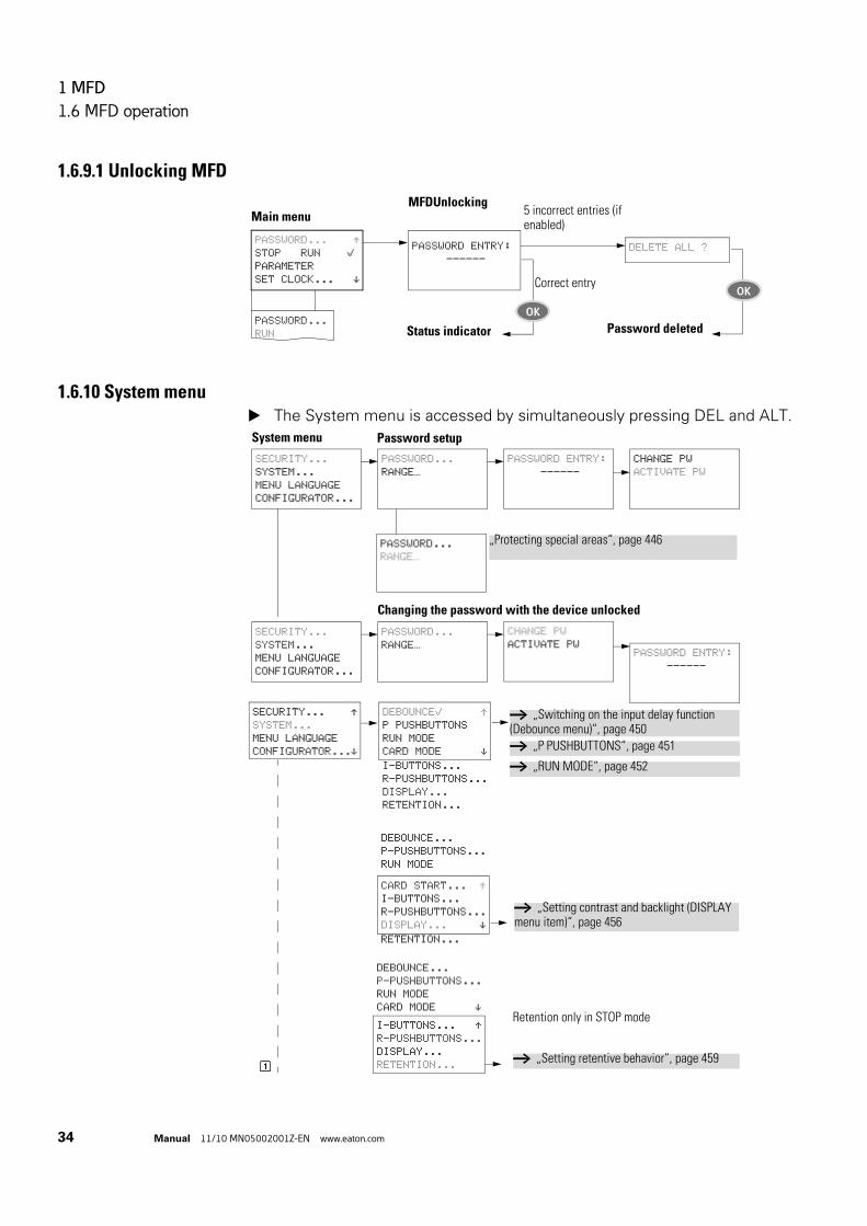
1 MFD
1.6 MFD operation
34 Manual 11/10 MN05002001Z-EN www.eaton.com
1.6.9.1 Unlocking MFD
1.6.10 System menu The System menu is accessed by simultaneously pressing DEL and ALT.
PASSWORD ENTRY:
------
MFDUnlocking
PASSWORD... ÆSTOP RUN åPARAMETER
SET CLOCK... æ
Main menu
PASSWORD...
RUN
DELETE ALL ?
Correct entry
Status indicator
5 incorrect entries (if enabled)
OKPassword deleted
OK
DEBOUNCEå ÆP PUSHBUTTONS
RUN MODE
CARD MODE æ
SECURITY... ÆSYSTEM...
MENU LANGUAGE
CONFIGURATOR...æI-BUTTONS...
R-PUSHBUTTONS...
DISPLAY...
RETENTION...
DEBOUNCE...
P-PUSHBUTTONS...
RUN MODE
CARD START... ÆI-BUTTONS...
R-PUSHBUTTONS...
DISPLAY... æRETENTION...
DEBOUNCE...
P-PUSHBUTTONS...
RUN MODE
CARD MODE æI-BUTTONS... ÆR-PUSHBUTTONS...
DISPLAY...
RETENTION...
Retention only in STOP mode
→ „Switching on the input delay function (Debounce menu)“, page 450
→ „P PUSHBUTTONS“, page 451
→ „RUN MODE“, page 452
→ „Setting contrast and backlight (DISPLAY menu item)“, page 456
→ „Setting retentive behavior“, page 459
System menu Password setup
SECURITY...
SYSTEM...
MENU LANGUAGE
CONFIGURATOR...
PASSWORD...
RANGE…
PASSWORD ENTRY:
------
CHANGE PW
ACTIVATE PW
PASSWORD...
RANGE…
„Protecting special areas“, page 446
PASSWORD ENTRY:
------
CHANGE PW
ACTIVATE PW
Changing the password with the device unlocked
SECURITY...
SYSTEM...
MENU LANGUAGE
CONFIGURATOR...
PASSWORD...
RANGE…
1

1 MFD
1.6 MFD operation
Manual 11/10 MN05002001Z-EN www.eaton.com 35
System menu
SECURITY...
SYSTEM...
MENU LANGUAGE
CONFIGURATOR...
SECURITY...
SYSTEM...
MENU LANGUAGE
CONFIGURATOR...
NET...
COM...
LINK...
ETHERNET-GW...
NET
PARAMETERS...
STATIONS...
CONFIGURE
Only one selection is possible.ENGLISH ÆDEUTSCH åFRANCAIS
ESPANOL æ
These menus are only displayed in STOP mode!
→ „NET parameterize“, page 123
→ „Changing the menu language“, page 461
1
NET
PARAMETERS...
STATIONS...
CONFIGURE
NET PARAMETER...
STATIONS...
CONFIGURE
→ „Creating the station list“, page 126
↓
NET...
COM...
LINK...
ETHERNET-GW
BAUD RATE:19200B
COM-LINK åREMOTE MARKER...
IO MODULES
NET...
COM...
LINK...
ETHERNET-GW
→ „Configuring NET“, page 127
→ „Baud rate adjustment“, page 134→ „activate COM-LINK“, page 134→ „Remote Specifying the marker range“, page 135
→ „Configuring the analog expansion unit“, page 117→ Communication expansion units in the relevant instructional leaflet
ITALIANO
PORTUGUES
NEDERLANDS
SVENSKA
POLSKI
TURKCE
IO MODULES
IO MODULES1

1 MFD
1.6 MFD operation
36 Manual 11/10 MN05002001Z-EN www.eaton.com
1.6.11 Selecting or toggling between menu items
1.6.12 Cursor display
System menu1
NET...
COM...
LINK...
ETHERNET-GW
IO MODULES
COM...
LINK...
ETHERNET-GW
IO MODULES
NET
SECURITY...
SYSTEM...
MENU LANGUAGE
CONFIGURATOR...
TAP13-PT-A
PARAMETERS...
DIAGNOSTICS...
INFORMATION...
PARAMETERS menu only in STOP mode.
TAP13-PT-A
PARAMETERS...
DIAGNOSTICS...
INFORMATION...
TAP13-PT-A
PARAMETERS...
DIAGNOSTICS...
INFORMATION...
→ Page 108
→ Page 116
→ Page 116
→ Configuration via RS232 interface in the manual MN05013012Z-DE (earlier: AWB2528-1596D)
Cursor Í Ú
Select or toggle
PROGRAM...
STOP
PARAMETER
SET CLOCK...
OK
The cursor flashes.
Full cursor Ê/:
• Move cursor with ú í,• in circuit diagram also with Í Ú
Value H/H
• Change position with ú í• Change values with Í ÚFlashing values/menus are shown in grey in this manual.
HH:MM â4:23TT.MM 05.05
YEAR 2003
HH:MM â4:23TT.MM 05.05
YEAR 2007
HH:MM 14:23
TT.MM 05.05
YEAR 2007

1 MFD
1.6 MFD operation
Manual 11/10 MN05002001Z-EN www.eaton.com 37
1.6.13 Setting values
Select value Í ÚSelect digit ú íChange value at digit Í Ú
Store settings
Retain previous value
Values Places Value at
HH:MM 14:23
TT.MM 08.10
YEAR 2010
OK
ESC

1 MFD
1.6 MFD operation
38 Manual 11/10 MN05002001Z-EN www.eaton.com

2 Installation
Manual 11/10 MN05002001Z-EN www.eaton.com 39
2 Installation
MFD devices must only be installed and wired up by qualified electricians or other persons familiar with the mounting of electrical equipment.
The MFD devices are installed in the following order:
• "Mounting the MFD", page 40.• "Mounting the expansion unit", page 54.• "Connecting the power supply", page 57.• "Connecting inputs", page 60.• "Connecting outputs", page 75.• "Connecting the NET network", page 82 (optional).• "Connecting the serial multi-function interface", page 88 (optional).
DANGER OF ELECTRIC SHOCK!
Never carry out electrical work on the device while the power supply is switched on.Always follow the safety rules:
• Switch off and isolate.• Verify isolation from the supply.• Secure against retriggering.• Short-circuit and ground.• Cover adjacent live parts.

2 Installation
2.1 Mounting the MFD
40 Manual 11/10 MN05002001Z-EN www.eaton.com
2.1 Mounting the MFD
Install the display/operating unit (MFD-80...) in the front of a control cabinet, a service distribution board, operator panel or in an enclosure. Install the power supply unit/CPU module (MFD-CP8.../CP10...) and the input/output module (I/O module) so that all the terminals are protected against direct contact, liquids and dust during operation.
When using the device without a display/operating unit, snap it onto a DIN EN 50 022 top-hat rail or fix it in place using fixing brackets. The MFD can be mounted either vertically or horizontally.
For ease of wiring, leave a gap of at least 3 cm between the device terminals and the wall or adjacent devices.
Figure 7: clearances to the MFD device.
Different installation steps must be carried out and sometimes in a different order, depending on the MFD combination you wish to use.
The following table provides an overview:
→ When using the MFD device with expansion units, connect the expansion unit concerned before mounting (→ section "2.2 Mounting the expansion unit", page 54).
30 m
m
(1.1
8“)
30 m
m
(1.1
8“)
30 mm
(1.18“)
30 mm
(1.18“)

2 Installation
2.1 Mounting the MFD
Manual 11/10 MN05002001Z-EN www.eaton.com 41
Table 6: Overview of mounting steps for the MFD device
MFD
-80
MFD
-CP
8/C
P10
MFD
-CP
8/C
P10
+ I/
O m
od
ule
s
MFD
-CP
8/C
P10
+ M
FD-8
0
MFD
-CP
8/C
P10
+ M
FD-8
0 +
I/O
mod
ules
"Fitting the protective diaphragm"
→ Page 42 (x) (x) (x)
"Fitting the protective cover on the MFD-80"
→ Page 43 (x) (x) (x)
"Mounting the MFD-CP8/CP10 on a top-hat rail"
→ Page 50 x x
"Screwing on the MFD-CP8/CP10"
→ Page 53 x x
"Mounting the expansion unit" → Page 54 x x
"Connecting the input/output module to the power supply unit/CPU module"
→ Page 48 x x
Mounting the I/O expansion on a top-hat rail
→ Page 54 (x) (x) (x) (x)
Screwing in the I/O expansion on the mounting plate
→ Page 54 (x) (x) (x) (x)
Connecting the I/O expansion to MFD-CP8/CP10 (easyLink)
(x) (x) (x) (x)
"Local expansion module" → Page 55 (x) (x) (x) (x)
"Remote expansion" → Page 56 (x) (x) (x) (x)
(x) = optional; MFD80 = display/HMI unit; MFD-CP8/CP10 = power supply/CPU module
→ In order to protect the MFD-80 with the protective diaphragm or protective cover, these must be fitted first of all, → Page 42 or page 43.

2 Installation
2.1 Mounting the MFD
42 Manual 11/10 MN05002001Z-EN www.eaton.com
2.1.1 Fitting the protective diaphragm/cover on the MFD-80
2.1.1.1 Fitting the protective diaphragmFor special applications such as in the food industry, the keypad must be protected against the ingress of dust, liquids etc.
For this use the specially designed protective diaphragm.Fit the protective diaphragm before mounting the display/operating unit.
Figure 8: Fitting the protective diaphragm
a Protective diaphragm
b Display/keypad
Fit the protective diaphragm over the display/operator unit.
Figure 9: Correct location of the protective diaphragm
DANGER
Ensure that the membrane fits snugly in the groove of the display/operator unit. Otherwise a proper seal cannot be guaranteed and particles may enter underneath the membrane. This may cause malfunctions in the keypad.In food industry applications, there is the risk of bacteria building up underneath the membrane.
a
b

2 Installation
2.1 Mounting the MFD
Manual 11/10 MN05002001Z-EN www.eaton.com 43
2.1.1.2 Fitting the protective cover on the MFD-80The protective cover is provided for using the device in aggressive environments. This protects the display and the keypad against mechanical damage or destruction. Protection type to IP65 is maintained.
The protective cover can be opened so that the operating unit can be used.
The protective cover can be closed with a sealing facility to provide protection against unauthorized operation.
Before mounting the display/operating unit, fit the protective cover.
Figure 10: Removing the front frame
Remove the front frame as shown in the figure.
The protective cover can be mounted in two different positions. Choose the position that is most suitable for the application at hand and your requirements.
→ If the protective diaphragm has to be replaced, the display/operating unit has to be removed. Replace the membrane and refit the device.

2 Installation
2.1 Mounting the MFD
44 Manual 11/10 MN05002001Z-EN www.eaton.com
Figure 11: Position of the protective cover
Figure 12: Mounting the protective cover
Mount the protective cover as shown in the figure.
2.1.1.3 Sealing the protective cover
Figure 13: Sealing the protective cover
The grip handle of the protective cover is provided with holes that can be used in any mounting position. You can fit a wire or similar material through these holes in order to seal the cover. If the wire is provided with a lead seal, the cover is sealed. The cover can then only be opened by breaking the seal or the wire.

2 Installation
2.1 Mounting the MFD
Manual 11/10 MN05002001Z-EN www.eaton.com 45
2.1.2 Front mounting of the MFD-80 display/HMI unit
Figure 14: Drill holes for the MFD
Drill and punch out two 22.5 mm diameter holes. The diameter is the same as is normally required for control circuit devices.
→ Observe the following technical requirements:• The hole spacing is 30 mm.• The maximum thickness of the front plate for mounting the
power supply/CPU module must not be more than 6 mm.• The maximum thickness of the front plate for mounting an
expansion unit with a top-hat rail in addition to the power supply/CPU module must not be more than 4 mm.
• Leave enough space at the side for the power supply unit/CPU module and, if necessary, the expansion unit.
• In order to ensure protection type to IP65, the surface of the mounting front must be even and smooth.
22.5 mm (0.89")
30 mm (1.18")

2 Installation
2.1 Mounting the MFD
46 Manual 11/10 MN05002001Z-EN www.eaton.com
Figure 15: Mounting the display/operator unit
Fit the display/operator unit in the punched fixing holes.
Figure 16: Screw fastening the display/operating unit
Screw fasten the display/operating unit.
The tightening torque must be between 1.2 and 2 Nm.
→ Ensure that the correct torque is used. If the tightening torque is too low or high, this may impair the seal.
2 x

2 Installation
2.1 Mounting the MFD
Manual 11/10 MN05002001Z-EN www.eaton.com 47
Figure 17: Rear of the mounted display/operator unit
Use the mounting ring tool with the designation M22-MS.
2.1.2.1 Removing the display/operating unit Unscrew the fixing element and remove the display/operator unit.
2.1.3 Connecting the power supply/CPU to the display/HMI unit
Figure 18: Connecting the power supply/CPU to the display/HMI unit: left without, right with the top-hat rail
→ If you wish to run the MFD device with an expansion unit, you must fit the top-hat rail on the power supply unit/CPU module before connecting the display/operating unit, → section "2.1.5.2 Use with display/HMI unit and expansion units", page 52.

2 Installation
2.1 Mounting the MFD
48 Manual 11/10 MN05002001Z-EN www.eaton.com
2.1.4 Connecting the input/output module to the power supply unit/CPU module
Figure 19: Fitting the input/output module
Figure 20: Power supply unit/CPU module with input/output module, left with, right without display/operating unit
→ You can connect the power supply unit/CPU module to the input output module (I/O module) and/or display/operating unit in any order.

2 Installation
2.1 Mounting the MFD
Manual 11/10 MN05002001Z-EN www.eaton.com 49
2.1.4.1 Removing the input/output module
Figure 21: Releasing the input/output module
Press the two catches together. Pull one side out of the catch. Pull the other side out of the second catch.
Figure 22: Removing the input/output module
Detach the input/output module.

2 Installation
2.1 Mounting the MFD
50 Manual 11/10 MN05002001Z-EN www.eaton.com
2.1.4.2 Removing the power supply/CPU moduleThe power supply unit/CPU module can be removed with or without the output module.
Figure 23: Releasing the fixing shaft
Use a screwdriver with a 100 x 3.5 mm slot width.
Insert the screwdriver into the strap of the fixing shaft catch. Lever out the slide catch. Pull out the power supply/CPU module from the fixing shafts.
2.1.5 Mounting the MFD-CP8/CP10 on a top-hat railIf you wish to run the power supply/CPU module without a display/HMI unit or with an expansion unit, you can fit it to a top-hat rail.
Alternatively you can also use the screw mounting, → section "2.1.6 Screwing on the MFD-CP8/CP10", page 53
2.1.5.1 Use without display/HMI unitThe fastening catches must be removed in order to mount the device on a fastened top-hat rail.
→ Undo any additional fixings on the top-hat rail.

2 Installation
2.1 Mounting the MFD
Manual 11/10 MN05002001Z-EN www.eaton.com 51
Figure 24: Removing the spring
Remove the spring with a screwdriver.
Figure 25: Pulling the slide catch and removing
Pull the slide catch out of the guide and remove it.
Figure 26: Snap fitting the device to the top-hat rail
Place the MFD device diagonally on the upper lip of the top-hat rail. Press down lightly on both the device and the top-hat rail until the unit snaps over the lower edge of the top-hat rail.
The MFD device will clip into place automatically.

2 Installation
2.1 Mounting the MFD
52 Manual 11/10 MN05002001Z-EN www.eaton.com
Check that the device is seated firmly.
The device is mounted vertically on a top-hat rail in the same way.
2.1.5.2 Use with display/HMI unit and expansion unitsEnsure that the cutout of the top-hat rail was prepared for the fixing shafts according to the specified dimensions.
Figure 27: Top-hat rail with cutout
Attach the expansion unit before fitting the top-hat rail.
Figure 28: Fitting the top-hat rail
→ The two fixing shafts of the display/operating unit are designed for a 2 space unit expansion unit.If you wish to fit wider expansion units, the top-hat rail must be supported at a third support point. This third support point should be located in the area 216 mm from the end of the device. It should not be possible to twist the top-hat rail.
DANGER
The fixing shafts of the display/operating unit are designed for mounting the expansion units. Other devices such as contactors must not be mounted on this top-hat rail.
24 35
38.75120
216
23.7560
30 g0.2

2 Installation
2.1 Mounting the MFD
Manual 11/10 MN05002001Z-EN www.eaton.com 53
Fit the top-hat rail in the groove using the slide catch of the power supply/CPU module and the expansion unit.
Turn the top-hat rail towards the housing. Let the top-hat rail snap into position. Press the power supply/CPU module onto the fixing shaft.
2.1.6 Screwing on the MFD-CP8/CP10You can also screw the power supply/CPU module onto a mounting plate, for example, if you wish to use it without a display/HMI unit or with an expansion unit.
Alternatively, you can mount the device on a top-hat rail, → section "2.1.5 Mounting the MFD-CP8/CP10 on a top-hat rail", page 50.
Fixing brackets that can be inserted on the rear of the MFD device are required for screw mounting. The fixing brackets are available as an accessory.
Figure 29: Inserting a fastening bracket
Figure 30: Screw mountingMFD
→ Three fixing brackets are sufficient for a device with four fixing points.
CLICK !

2 Installation
2.2 Mounting the expansion unit
54 Manual 11/10 MN05002001Z-EN www.eaton.com
2.2 Mounting the expansion unit
To increase the number of inputs/outputs, you can connect expansion units via the easyLink connection of the MFD basic devices.
Fit the expansion units in exactly the same way as a basic device on the top-hat rail or by screwing on fixing brackets.
Figure 31: Top-hat rail mounting
Figure 32: Screw mounting
Locally and remotely connected expansion units have a different connection.
Local expansion units are connected directly next to the MFD power supply/CPU module with easyLink.
With remote expansion, the expansion unit is connected via a two-wire or multi-core cable up to 30 m in length to the EASY200-EASY coupling device, which is connected directly to the basic device via the easyLink terminal.
EASY2..-… EASY4..-…, EASY6..-…
1
2

2 Installation
2.2 Mounting the expansion unit
Manual 11/10 MN05002001Z-EN www.eaton.com 55
2.2.1 Local expansion module Connect the easy expansion unit via the EASY-LINK-DS bus connector
plug.
Figure 33: Connecting local expansion with basic device
Figure 34: Mounting local expansion module on MFD-CP8.../CP10...
Specific system information is shown in the status display of the basic device (e.g. DC, AC or GW) depending on the expansion unit that is connected and operational.
DANGER
The following electrical isolation is implemented between the MFD power supply/CPU module and the expansion unit (isolation always in local connection of expansion unit):
• Basic isolation 400 V AC (+10 %).• Safe isolation 240 V AC (+10 %).Units may be destroyed if the value 400 V AC +10 % is exceeded, and may cause the malfunction of the entire system or machine!
→ Power supply unit/CPU modules and expansion units can be fed by different DC power supplies.
EASY-LINK-DS
EASY4…EEASY6…E
MFD-…-CP8/CP10…
EASY2…

2 Installation
2.2 Mounting the expansion unit
56 Manual 11/10 MN05002001Z-EN www.eaton.com
2.2.2 Remote expansionWith remote expansion module, you connect the expansion unit via a connecting cable to the EASY200-EASY coupling unit, which itself is fitted on the basic device via the easyLink terminal. The connecting cable can be up to 30 m in length.
Figure 35: Connecting remote expansion
DANGER
The two-wire or multiple-wire cable between the devices must adhere to the insulation voltage requirement which is stipulated for the installation environment. Otherwise, a fault scenario (ground fault, short-circuit) may lead to the destruction of the units or injury to persons.A cable, such as NYM-0 with a rated operational voltage Ue = 300/500 V AC, is normally sufficient.
→ Terminals E+ and E– of the EASY200-EASY are protected against short-circuits and polarity reversal. Functionality is only ensured if E+ is connected with E+ and E- with E-.
E+ E–
E+ E–
Ue = 300/500 V
MFD-...-CP8.. EASY200-EASY
EASY4..-..-.EEASY6..-..-.E

2 Installation
2.3 Terminations
Manual 11/10 MN05002001Z-EN www.eaton.com 57
2.3 Terminations
2.3.1 ToolsFlat blade screwdriver, blade width 3.5 x 0.6 mm, for use on the spring-cage terminal.
2.3.2 Cable cross-sections• Solid: 0.2 to 4 mm2 (AWG 22 -12).• Flexible with ferrule: 0.2 to 2.5 mm2.
How to connect the easyNet network → section "2.7 Connecting the NET network", page 82.
2.4 Connecting the power supply
2.4.1 Cable protectionWith the AC and DC variant of the power supply unit/CPU module and with the expansion unit connect cable protection (F1) of at least 1 A (slow).
CAUTION
When the basic devices and expansion units are switched on, they behave like a capacitor, so that an inrush current higher than the rated input current is present. Take this inrush current into account when designing the electrical equipment by using slow fuses and suitable switches. Never use reed relay contacts to switch the supply voltage as these may burn or stick.When designing the DC power supply unit, bear the inrush current in mind and use time-lag fuses.
→ The relevant connection data for the different device types → Chapter "MFD-80.. display/operator unit", page 495.The devices run a system test for one second after the supply voltage has been switched on. After this time the device switches to RUN or STOP operating mode depending on the default setting.
DANGER
Ensure that the L and N conductor are not reversed.

2 Installation
2.4 Connecting the power supply
58 Manual 11/10 MN05002001Z-EN www.eaton.com
2.4.2 MFD-AC... power supply unit/CPU module
Figure 36: Power supply on the MFD, AC variant
2.4.3 AC expansion unit EASY618-AC-RE
Figure 37: Power supply on the AC expansion unit
N NL
L
N
> 1 A
NNL
N
F1
L
115/230 V ~E+ E- R1 ... R12

2 Installation
2.4 Connecting the power supply
Manual 11/10 MN05002001Z-EN www.eaton.com 59
2.4.4 MFD-... DC power supply/CPU module
Figure 38: Power supply on the MFD, DC variant
The power supply/CPU module supplies the display/HMI unit, the input/output electronics as well as the optional easyNet network with the necessary power supply.
2.4.5 DC expansion unit EASY…-DC-.E
Figure 39: Power supply on the DC expansion unit
→ DC basic devices and expansion units are protected against reverse polarity. However, you must ensure the correct polarity so that the devices function reliably and safely.
L01–
> 1 A
L01+ L02+
+24V 0V 0V
0V0V24V
L01-
F1
L01+
E+ E- R1 ... R12
24 V H

2 Installation
2.5 Connecting inputs
60 Manual 11/10 MN05002001Z-EN www.eaton.com
2.5 Connecting inputs
The inputs of the MFD devices switch electronically. Once you have connected a contact via an input terminal, you can reuse it as a contact in your circuit diagram as often as you like.
Connect the contacts, for example pushbuttons or switches, to the input terminals of the MFD device.
Figure 40: Connecting input, in this case I 1.
See also:
• "Connect digital AC inputs", page 61.• "Connecting easy DC digital inputs", page 65.• "Connecting analog inputs", page 69.
When using special function blocks, certain inputs are permanently assigned to these function blocks and cannot be used for any other purpose. The relevant function block description describes which inputs are affected.
Example: With the “high-speed counter” function block, the device inputs I1 - I4 are connected directly on one function block.
You can increase the number of inputs of the MFD device (basic device) by using an expansion unit. The inputs of the EASY4..-DC-.E and EASY6..-DC-.E digital expansion units are detected by the basic device automatically - without any configuration.
See also:
• "Connect digital AC inputs", page 62.• "Connecting easy DC digital inputs", page 68.
The universal EASY4..-DC-ME expansion units allow you to process both digital and analog values. The digital inputs of these expansion units are detected by the basic device automatically - without any configuration. The analog inputs/outputs must normally be configured.
See also:
• "Connect digital AC inputs", page 62.• "Connecting easy DC digital inputs", page 68.• "Connecting analog inputs", page 73.
+24 V
S1
0 VI1
I1 i1
L
N

2 Installation
2.5 Connecting inputs
Manual 11/10 MN05002001Z-EN www.eaton.com 61
2.5.1 Connect digital AC inputs
2.5.1.1 Connecting AC inputs of the basic device MFD-AC-R16
Figure 41: Connecting inputs on the AC basic device MFD-AC-R16
• Input signal voltage range• Off signal: 0 to 40 V.• On signal: 79 to 264 V
• Input current• I1 to I12: 0.5 mA/0.25 mA at 230 V/115 V.
DANGER
Connect the inputs for AC basic and expansion units in accordance with the safety regulations of VDE, IEC, UL and CSA with the same phase conductor that provides the power supply voltage. The device will otherwise not detect the switching level or may be destroyed by overvoltage.Connect the inputs for AC basic and expansion units in accordance with the safety regulations of VDE, IEC, UL and CSA with the same phase conductor that provides the power supply voltage. The device will otherwise not detect the switching level or may be destroyed by overvoltage.
DANGER
The AC inputs must only be used together with the MFD-AC-CP8-.. power supply/CPU modules. Other power supply/CPU modules may be destroyed.
N
> 1 A
L
I1 I3 I4 I7 I8I2 I5 I6 I9 I10 N NI11 I12
L N N

2 Installation
2.5 Connecting inputs
62 Manual 11/10 MN05002001Z-EN www.eaton.com
2.5.1.2 Connecting AC inputs of the expansion unit EASY618-AC-RE
Figure 42: Connecting inputs on the easy618-AC-RE AC expansion unit
Connect the inputs, for example, to pushbutton actuators, switches or relay/contactor contacts.
• Input signal voltage range• Off signal: 0 to 40 V.• On signal: 79 to 264 V
• Input current• R1…R12: 0.5 mA/ 0.25 mA at 230 V/ 115 V.
Length of input cables
Severe interference can cause a signal 1 on the inputs without a proper signal being applied. Observe therefore the following maximum cable lengths:
• I1 to I12 and R1 to R12: 40 m without additional circuit
The following also applies to the expansion units:With longer cables connect a diode (e.g. 1N4007) with a minimum reverse voltage of 1 kV and a forward current of 1 A in series to the device input. Ensure that the diode is pointing to the input as shown in the circuit diagram; otherwise the device will not be able to detect the 1 state.
Figure 43: Connecting inputs on the EASY618-AC-RE AC expansion unit via diodes
L
N
R10R9R8R7R6R5R4R3R2R1E+ E– R11 R12 NNL
115/230 V h
F1
L
N
R10R9R8R7R6R5R4R3R2R1E+ E– R11 R12 NNL
115/230 V h
F1
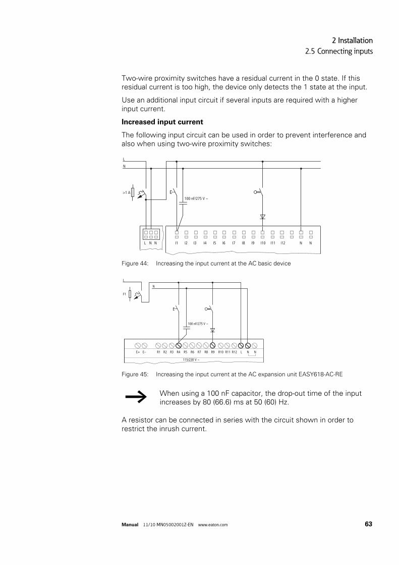
2 Installation
2.5 Connecting inputs
Manual 11/10 MN05002001Z-EN www.eaton.com 63
Two-wire proximity switches have a residual current in the 0 state. If this residual current is too high, the device only detects the 1 state at the input.
Use an additional input circuit if several inputs are required with a higher input current.
Increased input current
The following input circuit can be used in order to prevent interference and also when using two-wire proximity switches:
Figure 44: Increasing the input current at the AC basic device
Figure 45: Increasing the input current at the AC expansion unit EASY618-AC-RE
A resistor can be connected in series with the circuit shown in order to restrict the inrush current.
→ When using a 100 nF capacitor, the drop-out time of the input increases by 80 (66.6) ms at 50 (60) Hz.
L
N
>1 A
I1 I3 I4 I7 I8I2 I5 I6 I9 I10 N NI11 I12L N N
100 nF/275 V h
L
N
R10R9R8R7R6R5R4R3R2R1E+ E– R11 R12 NNL
115/230 V h
F1
100 nF/275 V h

2 Installation
2.5 Connecting inputs
64 Manual 11/10 MN05002001Z-EN www.eaton.com
Figure 46: Limitation of the input current with a resistor at the AC basic device
Figure 47: Limitation of the input current with a resistor at the AC expansion unit EASY618-AC-RE
Complete devices for increasing the input current are available under the part no. EASY256-HCI.
Figure 48: AC basic device with EASY256-HCI to increase the input current
L
N
>1 A
I1 I3 I4 I7 I8I2 I5 I6 I9 I10 N NI11 I12L N N
100 nF/275 V h1 kO
L
N
R10R9R8R7R6R5R4R3R2R1E+ E– R11 R12 NNL
115/230 V h
F1
100 nF/275 V h
1 kO
L
N
>1 A
I1 I3 I4 I7 I8I2 I5 I6 I9 I10 N NI11 I12L N N

2 Installation
2.5 Connecting inputs
Manual 11/10 MN05002001Z-EN www.eaton.com 65
Figure 49: AC expansion unit with EASY618-AC-RE with EASY256-HCI to increase the input current
2.5.2 Connecting easy DC digital inputs
2.5.2.1 Connecting DC inputs of the basic devices MFD-R.16(17) and MFD-T.16(17)Connect pushbutton actuators, switches, 3 or 4-wire proximity switches to input terminals I1 to I12 of the DC basic device (standard I/O module). Given the high residual current, do not use 2-wire proximity switches.
These DC basic devices enable you to read both digital and analog input signals via the inputs I7 (IA01), I8 (IA02), I11 (IA03) and I12 (IA04).
• Digital input signal voltage range• I1 to I6, I9, I10.
Signal OFF: 0 to 5 V. Signal ON: 15 to 28.8 V.
• I7, I8, I11, I12.Signal OFF: < 8 V. Signal ON: > 8 V.
• Input current:• I1 to I6, I9, I10, R1 to R12: 3.3 mA at 24 V• I7, I8, I11, I12: 2.2 mA at 24°V
→ The increased capacitance increases the drop-off time by approx. 40 ms.
L
N
R10R9R8R7R6R5R4R3R2R1E+ E– R11 R12 NNL
115/230 V h
F1
→ Feed the digital inputs from the same 24 V DC power source as the device.

2 Installation
2.5 Connecting inputs
66 Manual 11/10 MN05002001Z-EN www.eaton.com
Figure 50: Example application with DC basic device MFD-R.16(17) and MFD-T.16(17)
2.5.2.2 Connecting DC inputs of the basic devices MFD-TP…/MFD-TAP…The MFD-TP…/MFD-TAP… I/O modules (I/O modules with temperature measuring) are provided with four digital DC inputs (terminal I1 - I4). In addition to this, you can also use the analog inputs I11 (IA03) and I12 (IA04), which are provided for 0 V - 10 V analog value measuring, for use with digital input signals (→ section "2.5.3.2 Connecting analog and temperature inputs of MFD-TP…/MFD-TAP…", page 72).
• Digital input signal voltage range• I1 to I4
Signal OFF: -30 to 5 V. Signal ON: 15 to 28.8 V.
• I11, I12Signal OFF: < 8 V. Signal ON: > 8 V.
• Input current:• I1 to I4: 3.3 mA at 24 V.• I11, I12: 2.2 mA at 24 V.
L01–
> 1 A
L01+
I1 I3 I4 I7 I8 I9 I10
L02+
I2 I5 I6 I11 I12+24V 0V 0V
→ Feed the digital inputs from the same 24 V DC power source as the device.

2 Installation
2.5 Connecting inputs
Manual 11/10 MN05002001Z-EN www.eaton.com 67
Figure 51: Example application with DC basic device MFD-TP…/MFD-TAP…, processing of digital input signals
a DC inputs (terminal I1 - I4).
b Analog inputs 0 V - 10 V (terminal I11, I12).
Connecting high-speed counters and frequency generators
The digital inputs I1 - I4 of the standard I/O module and I/O module with temperature measuring allow you to accurately measure high-speed counter signals or frequencies and bypass the cycle time.
Figure 52: High-speed counter, frequency encoder on standard I/O module
L01–
> 1 A
L01+
I1 I3 I4 I7 I8 I9 I10
L02 +
I2 I5 I6 I11 I12+24 V 0 V 0 V
ba
L01–
> 1 A
L01+
I1 I3 I4 I7 I8 I9 I10
L02+
I2 I5 I6 I11 I12+24V 0V 0V

2 Installation
2.5 Connecting inputs
68 Manual 11/10 MN05002001Z-EN www.eaton.com
Connecting incremental encoders
The standard I/O module and I/O module with temperature measuring allow you to connect one incremental encoder each to the digital inputs I1, I2, I3 and I4.
This enables you to count high-speed incremental values independently of the cycle time. The incremental encoder must output two 24 V DC square wave signals with a phase offset.
Figure 53: Connecting incremental encoders
2.5.2.3 Connecting DC inputs of the expansion units EASY410... and EASY6...
Figure 54: EASY410-.C-.E and EASY6..-DC-.E (digital expansion unit)
Connect the inputs, for example, to pushbutton actuators, switches or relay/contactor contacts.
• Input signal voltage range• R1 to R6 (EASY410...), or R1 to R12 (EASY6...)
Signal OFF: 0 to 5 V. Signal ON: 15 to 28.8 V.
• Input current• R1…R6 or R12: 3.3 mA at 24 V
L01–
> 1 A
L01+
I1 I3 I4 I7 I8 I9 I10
L02+
A B
I2 I5 I6 I11 I12+24V 0V 0V
R3R2R1E+ E-
24 V H
…
EASY4-…-.EEASY6-…-.E

2 Installation
2.5 Connecting inputs
Manual 11/10 MN05002001Z-EN www.eaton.com 69
2.5.2.4 Connecting DC inputs of the EASY4..-DC-ME expansion unitsIn addition to the analog inputs/outputs, the EASY4..-DC-ME DC expansion units are provided with the digital input R1. In addition to R1 you can also always use the analog 0 V - 10 V voltage inputs R2/R3 (terminals 2 and 7) as additional digital inputs and actuate them with up to 24 V DC.
Both expansion devices show a 0 signal at R2/R3 if the voltage goes below 8 V DC and a 1 signal if the voltage exceeds this value.
Figure 55: Digital inputs of the EASY4..-DC-ME
Further information on the voltage range and input current of the input signals → section "2.5.2 Connecting easy DC digital inputs", page 65.
2.5.3 Connecting analog inputsAll power supply/CPU modules with a 24V DC power supply can be fitted with a standard I/O module or an I/O module with temperature measuring, which each have digital and analog inputs.
On the MFD, it is also possible to connect the EASY406-DC-ME and EASY411-DC-ME DC expansion unit (→ section "2.5.2.4 Connecting DC inputs of the EASY4..-DC-ME expansion units", page 69).
→ R2/R3 can always be used as additional digital inputs, even if they have not been expressly configured in the programming software as analog voltage inputs. Current and temperature inputs cannot be used as digital inputs.
0 V
L01+
L01-
R1 R2 R3 0 V

2 Installation
2.5 Connecting inputs
70 Manual 11/10 MN05002001Z-EN www.eaton.com
Use shielded or twisted pair cables. Keep signal cables as short as possible and not longer than 10 m. With short cable lengths ground the shield of the signal cables at both
ends with a large surface area connection. With longer signal cables, the shield should only be grounded at one end, on the side of the MFD or expansion unit. Otherwise compensation currents between both grounding points may flow, leading to the interference of analog signals.
Lay signal cables separately from heavy current cables. Connect inductive loads to be switched via the MFD device outputs to a
separate power feed, or use a suppressor circuit for motors and valves. If loads such as motors, solenoid valves or contactors and MFD are operated with the same power feed, switching may give rise to interference on the analog input signals.
Ensure a galvanic connection of the reference potential as described below.
Avoid the operation of the MFD or expansion unit on an ungrounded power supply.
2.5.3.1 Connecting analog inputs of the basic deviceYou can read analog voltages in the range 0 to 10 V via the inputs I7, I8, I11 and I12 of the DC basic device MFD-R.16(17) and MFD-T.16(17).
The signal has a 10-bit resolution, value range 0 - 1 023.
The following therefore applies:
• I7 = IA01• I8 = IA02• I11 = IA03• I12 = IA04
The analog voltage inputs can also be used as digital inputs.
DANGER
Analog signals are more susceptible to interference than digital signals, so that the signal cables must be laid and connected more carefully. The measures described below must be adhered to in order to prevent any deviations in analog values. An incorrect connection can lead to unwanted switching states.
→ You can also use an MFD-TP…/MFD-TAP… DC basic unit (I/O modules with temperature measuring) for analog value measuring (→ section "2.5.3.2 Connecting analog and temperature inputs of MFD-TP…/MFD-TAP…", page 72).

2 Installation
2.5 Connecting inputs
Manual 11/10 MN05002001Z-EN www.eaton.com 71
The following circuits are examples of using the analog value measuring via inputs of the DC basic device.
Setpoint potentiometer
Figure 56: Setpoint potentiometer with upstream resistor
Use a potentiometer with the resistance ≤1 kΩ e.g. 1 kΩ, 0.25 W.
Temperature , brightness and 20 mA sensor
Figure 57: MFD-R.16(17) and MFD-T.16(17) with temperature, brightness and 20 mA sensor
① Analog sensor
A 4 to 20 mA (0 to 20 mA) sensor can be connected on the voltage input using an external 500 Ω resistor (twice 1 kΩ in parallel).
→ Ensure that the reference potential is galvanically connected. Connect the 0 V of the power supply unit for the different setpoint potentiometers and sensors shown in the examples to the 0 V terminal of the MFD power supply.
L01–
> 1 A
L01+
I1 I3 I4 I7 I8 I9 I10
L02+
I2 I5 I6 I11 I12
0 V +12 V
Hh
1.3 kO/0.25 W
1 kO/0.25 W
+24V 0V 0V
L01–
> 1 A
L01+
I1 I3 I4 I7 I8 I9 I10
L02+
I2 I5 I6 I11 I12+24V 0V 0V
0...10 V
0 V +12 V
hH
+24 V H
0 V
Out0...10 V
–35...55 ˚Ca
500 O
4...20 mA

2 Installation
2.5 Connecting inputs
72 Manual 11/10 MN05002001Z-EN www.eaton.com
The following values apply:
• 4 mA = 2.0 V• 10 mA = 5.0 V• 20 mA = 10.0 V
(according to U = R x I = 500 Ω x 10 mA = 5.0 V)
2.5.3.2 Connecting analog and temperature inputs of MFD-TP…/MFD-TAP…You can use an MFD-TP… or MFD-TAP… DC basic unit to connect PT100 and NI1000 temperature sensors directly to the MFD and also measure voltages. The temperatures are measured with a 12-bit resolution (0 - 4095) and can be set to different measuring ranges between -200 °C and 850 °C.
Figure 58: Connecting the analog and temperature inputs on the MFD-TP…/MFD-TAP…
a Temperature input (example three-wire connection).
b Temperature input (example two-wire connection).
c Analog IN, I11=IA03, I12=IA04.
d Analog OUT, QA01 (only MFD-TAP13-...).
The temperature sensors can be connected directly to the three terminals of inputs IA01 (terminal I5 - I7) and IA02 (terminal I8 - I10). A three-wire connection or a two-wire connection is possible, → Figure 58, page 72. On terminals I5 and I8, the temperature module outputs a constant current to the temperature sensor.
With three-wire measuring, the line resistance is compensated by means of a measuring bridge in the temperature module.
With two-wire connections, connect a short-circuit bridge between terminals I5 and I6 or I8 and I9.
L01–
> 1 A
L01+
I1 I3 I4 7 8 9 10 0V QA 1
0V
L02 +
A B 10 V
5 V
0 V0 512 1023
+10 V0 V
I11, I12
~
I2 5 6 I11 I12 0V+24 V 0 V 0 V
a b c d

2 Installation
2.5 Connecting inputs
Manual 11/10 MN05002001Z-EN www.eaton.com 73
The analog inputs I11 ( IA03) and I12 (IA04) are used for analog value measurement between 0 V - 10 V (10-bit resolution; 0 - 1023). These inputs can also be used as digital inputs, → Figure 51, page 67.
A separate sensor monitoring is provided for an activated temperature input. It monitors:
• Short-circuit.• Wire breakage or sensor errors.• Out of range values.
This type of error is indicated by a diagnostics contact (→ Section "9.3 Diagnostics", page 479).
Modules with ..TAP13.. in their designation are provided with an additional analog output.
Table 7: I/O module MFD-TP…/MFD-TAP… and sensor type
2.5.3.3 Connecting analog inputs of the EASY4..-DC-ME expansion unitsThese DC expansion units allow you to process analog values of voltage, current and temperature. The EASY4..-DC-ME DC expansion units convert analog input and output values with a 10-bit resolution (0 - 1023). When a Pt100 sensor is connected, the DC expansion units operate in the range between -50 °C and 200 °C.
The DC expansion units are provided with digital inputs/outputs as well as analog inputs/outputs (→ Section "2.5.2.4 Connecting DC inputs of the EASY4..-DC-ME expansion units",page 69).
DANGER
Do not connect an external voltage, i.e. also no analog input voltage in the range up to 10 V, to the sensor inputs 1 and 2. An external voltage will destroy the temperature module and the power supply/CPU module.
Designation Sensor type Measuring range
Resolution Accuracy
MFD-TP12-PT-A (MFD-TAP13-PT-A)
Pt100 -40...+90 °C 12 Bit (0.03 °C) 0.6% (~0.8 °C)
0...+250 °C 12 Bit (0.06 °C) 0.6% (~1.5 °C)
0...+400 °C 12 Bit (0.1 °C) 0.6% (~2.4 °C)
MFD-TP12-PT-B(MFD-TAP13-PT-B)
0...+850 °C 12 Bit (0.21 °C) 0.6% (~5.1 °C)
-200...+200 °C 12 Bit (0.1 °C) 0.6% (~2.4 °C)
MFD-TP12-NI-A(MFD-TAP13-NI-A)
Ni1000 -40...+90 °C 12 Bit (0.03 °C) 0.6% (~0.8 °C)
0...+250 °C 12 Bit (0.06 °C) 0.6% (~1.5 °C)
→ You process the analog input and output values using permanently assigned marker words (MW) which you configure and program in easySoft-Pro

2 Installation
2.5 Connecting inputs
74 Manual 11/10 MN05002001Z-EN www.eaton.com
Two devices are available:
• With the EASY406-DC-ME you can read one voltage, current or temperature analog value via the first analog input (terminals 2 - 6) and via the second analog input (terminals 7 - 11).
• The EASY411-DC-ME allows you to evaluate measured values at the same time via the six analog inputs (terminals 2...11), and read voltage, current or temperature analog values via two inputs each.
Table 8: Terminals of the analog inputs on the EASY4..-DC-ME expansion devices
Figure 59: Connection of the analog inputs on the EASY4..-DC-ME expansion devices
Voltages are measured in the 0 - 10 V signal range. A potentiometer with an upstream resistor that is connected between the supply voltage and reference potential can be used as a setpoint potentiometer. For voltage measuring, connect the output of the sensor to the voltage input (terminal 2 or 7), → section "Figure 56: Setpoint potentiometer with upstream resistor", page 71.
Currents are measured in the 4 - 20 mA (0 - 20 mA) signal range. For current measurement connect the output of the sensor to the current input (terminal 3 or 8), → section " Temperature , brightness and 20 mA sensor", page 71.
Terminal(s)
EASY406-DC-ME Meaning EASY411-DC-ME Meaning
2 1. Analog value 0 - 10 V, 0(4)-20 mA or PT100 resistance sensor
1. Analog value 0 - 10 V
3 1. Analog value 2. Analog value 0(4)-20 mA
4, 5, 6 1. Analog value 3. Analog value PT100 resistance sensor
7 2. Analog value 0 - 10 V, 0(4)-20 mA or PT100 resistance sensor
4. Analog value 0 - 10 V,
8 2. Analog value 5. Analog value 0(4)-20 mA
9, 10, 11 2. Analog value 6. Analog value PT100 resistance sensor
L01+
L01-
i i
1 2 3 4 5 6 7 8 9 10 11
0(4)-20 mA
+10 V0 V
0 V

2 Installation
2.6 Connecting outputs
Manual 11/10 MN05002001Z-EN www.eaton.com 75
Temperatures are measured in the range -50…+200 °C using PT100 temperature sensors. The sensor inputs 1 (terminal 4 - 6) and 2 (terminal 9 - 11) are used for temperature measuring.
On terminals 6 and 11, the analog expansion unit outputs a constant current to the temperature sensor.
Connect the ground connection of a sensor to the corresponding 0 V input (terminal 4 or 9) of the expansion unit.
You connect the temperature sensor directly to the relevant three terminals of these sensor inputs. A three-wire connection or a two-wire connection is possible.
With three-wire measuring, the line resistance is compensated by means of a measuring bridge in the expansion unit.
With two-wire connections, connect a short-circuit bridge between terminals 5 and 6 or 10 and 11 (→ Figure 59, page 74).
2.6 Connecting outputsDevices either have transistor outputs or relay outputs. The Q... outputs of both device versions are potentially isolated from the power supply and the inputs, and therefore operate as potential-free contacts.
Figure 60: Connecting outputs, in this case Q 1
The respective relay coils are actuated in the circuit diagram via the Q 01 to Q 04 or S 01 to S 06 (S 08) output relays.
You can use the signal states of the output relays as N/O or N/C contacts in the circuit diagram for additional switching conditions.
→ When current measuring is activated, we recommend the implementation of wire break detection via the diagnostics contact R13. The expansion unit switches the diagnostics contact to the 1 state if a current < 3 mA is present. Use current sensors for the 4 - 20 mA signal range if you wish to evaluate the diagnostics contact.
→ The inputs and outputs of these analog expansion units require the same reference potential (chassis ground) as the DC power supply of the sensors and actuators.Connect the 0V of the DC power supply of the different sensors with the 0V of the DC power supply of the expansion unit.
Q1 q1Q1
1 2
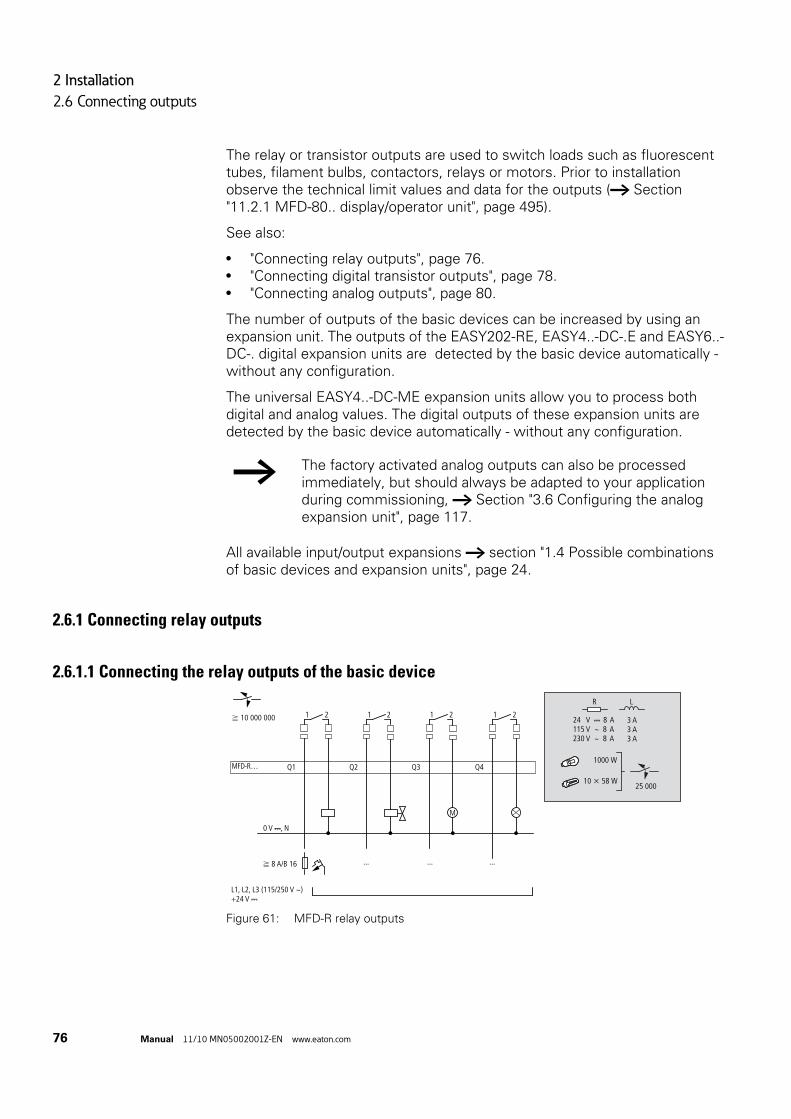
2 Installation
2.6 Connecting outputs
76 Manual 11/10 MN05002001Z-EN www.eaton.com
The relay or transistor outputs are used to switch loads such as fluorescent tubes, filament bulbs, contactors, relays or motors. Prior to installation observe the technical limit values and data for the outputs (→ Section "11.2.1 MFD-80.. display/operator unit", page 495).
See also:
• "Connecting relay outputs", page 76.• "Connecting digital transistor outputs", page 78.• "Connecting analog outputs", page 80.
The number of outputs of the basic devices can be increased by using an expansion unit. The outputs of the EASY202-RE, EASY4..-DC-.E and EASY6..-DC-. digital expansion units are detected by the basic device automatically - without any configuration.
The universal EASY4..-DC-ME expansion units allow you to process both digital and analog values. The digital outputs of these expansion units are detected by the basic device automatically - without any configuration.
All available input/output expansions → section "1.4 Possible combinations of basic devices and expansion units", page 24.
2.6.1 Connecting relay outputs
2.6.1.1 Connecting the relay outputs of the basic device
Figure 61: MFD-R relay outputs
→ The factory activated analog outputs can also be processed immediately, but should always be adapted to your application during commissioning, → Section "3.6 Configuring the analog expansion unit", page 117.
0 V H, N
L1, L2, L3 (115/250 V h)+24 V H
Q1
1 2
f 8 A/B 16
f 10 000 000
Q2
1 2
... ... ...
Q3
1 2
M
Q4
1 2
MFD-R…
25 000
R L
24 V H 8 A115 V h 8 A230 V h 8 A
3 A3 A3 A
1000 W
10 x 58 W

2 Installation
2.6 Connecting outputs
Manual 11/10 MN05002001Z-EN www.eaton.com 77
2.6.1.2 Connecting the relay outputs of the expansion unitEASY4..-..-RE/EASY6..-..-RE
Figure 62: EASY4..-..-RE/EASY6..-..-RE relay outputs
EASY2..-RE
Figure 63: EASY2..-RE relay outputs
Unlike the connection of the inputs, you can connect different phase conductors to the relay outputs of the MFD-R.. devices.
DANGER
Do not exceed the maximum voltage of 250 V AC on a relay contact. If the voltage exceeds this threshold, flashover may occur at the contact, resulting in damage to the device or a connected load.
10 000 000
0 V H, N
L1, L2, L3 (115/250 V h)+24 V H
S1
1 2
S1
EASY4-…-RE
EASY6-…-RE
F 8 A/B 16
S2
1 2
S2
... ... ... ... ...
S3
1 2
S3
M
S4
1 2
S4
1 2
S5
1 2
S6
25 000
R L
24 V H 8 A115 V h 8 A230 V h 8 A
3 A3 A3 A
1000 W
10 x 58 W
+ 24 V H
0 V H, N
F 8 A/B 16L1, L2, L3 (115/230 Vh)
1 2 21
10 000 000S2S1
+ 24 V H
0 V H, N
F 8 A/B 16L1, L2, L3 (115/230 Vh)
1 2 21
10 000 000S2S1

2 Installation
2.6 Connecting outputs
78 Manual 11/10 MN05002001Z-EN www.eaton.com
2.6.2 Connecting digital transistor outputs
2.6.2.1 Connecting transistor outputs of the basic device
Figure 64: Digital transistor outputs of the MFD-T... I/O modules and MFD-TP…/MFD-TAP…
2.6.2.2 Connecting transistor outputs of the expansion unit
Figure 65: Digital transistor outputs EASY6..-DC-TE and EASY4...-DC-TE
a EASY4... -DC-TE
b EASY6... -DC-TE
→ Power the transistor outputs with voltage!
0 VQ Q1 Q2 Q3 Q4
F 10 A
24 VQ
f 2.5 A
24 V H
(20.4 – 28.8 V H)+ 24 V H
R L
5 W/24 V
0.5 A24 V H 0.5 A
F 10 A
f 2.5 A
0 V H
0 VQ24 VQ
a a
b
(20.4 – 28.8 V H)+ 24 V H
R L
5 W/24 V
0.5 A24 V H 0.5 A

2 Installation
2.6 Connecting outputs
Manual 11/10 MN05002001Z-EN www.eaton.com 79
Parallel connection
Up to four outputs can be connected in parallel in order to increase the power. This enables a maximum output current of 2 A.
If inductive loads are not suppressed, the following applies: Several inductive loads should not be switched off simultaneously to avoid overheating the driver blocks in the worst possible case. If in the event of an emergency stop the +24 V DC power supply is to be switched off by means of a contact, and if this would mean switching off more than one controlled output with an inductive load, then you must provide suppressor circuits for these loads (→ Figure 66, page 79).
Figure 66: Inductive load with suppressor circuit
2.6.2.3 Behavior in the event of a short-circuit/overloadA transistor output will switch off in the event of a short-circuit or overload. The output will switch back on up to the maximum temperature after a cooling time that depends on the ambient air temperature and the current level. If the fault condition persists, the output will keep switching off and on until the fault is corrected or until the power supply is switched off (→ Section "9.3 Diagnostics", page 479).
DANGER
Only outputs of the same group (S1 to S4 or S5 to S8) can be connected in parallel; e.g. S1 and S3 or S5, S7 and S8. Outputs connected in parallel must be switched at the same time.
DANGER
Please note the following when switching off inductive load.• Suppressed inductances cause less interference in the
entire electrical system. It is recommended that the suppressor circuit is connected as close to the inductance as possible.
+ 24 V H
Q., S.
Uemax < UZ < 33 V
0 V H
Q., S.

2 Installation
2.6 Connecting outputs
80 Manual 11/10 MN05002001Z-EN www.eaton.com
2.6.3 Connecting analog outputsAll power supply/CPU modules with a 24V DC power supply can be fitted with an MFD-A17 standard I/O module or an MFD-TAP... I/O module as a basic unit, each have one QA 01 analog input. QA 01 enables you to output a DC voltage of 0 - 10 V.
• Standard I/O module, type MFD-RA.. and MFD-TA.., 10-bit resolution, value range 0 - 1023
• I/O module type MFD-TAP.., 12-bit resolution, value range 0 - 4095.
It is also possible on the MFD to connect the EASY406-DC-ME and EASY411-DC-ME DC expansion units with an analog output (→ Section "2.5.2.4 Connecting DC inputs of the EASY4..-DC-ME expansion units", page 69).
The analog output can be used, for example, for controlling solenoid valves and other actuators.
Observe the hazard warnings concerning the processing of analog signals (→ section "2.5.3 Connecting analog inputs", page 69) and the note concerning the same reference potential (chassis ground).
2.6.3.1 Connecting analog output of the MFD-.A17 and MFD-TAP… basic devicesConnect the actuator to QA1 and to the 0V terminal on its left.
Connecting servo valves
Figure 67: Connecting servo valves
L01–
> 1 A
L01+
I1 I3 I4 I7 I8 I9 I10 0V QA 1
L02+
A B
I2 I5 I6 I11 I12 0V+24V 0V 0V

2 Installation
2.6 Connecting outputs
Manual 11/10 MN05002001Z-EN www.eaton.com 81
Setpoint entry for a drive
Figure 68: Setpoint entry for a drive
2.6.3.2 Connecting analog output of the EASY4..-DC-ME expansion unitsAnalog expansion units are used to increase the number of outputs. The EASY406-DC-ME analog expansion unit offers you one and the EASY411-DC-ME two additional analog outputs. Both devices provide a DC voltage of 0 - 10 V with a 10-bit resolution, value range 0 - 1023. Connect the actuator(s) to QA1(/QA2) and to the relevant 0 V terminal to its left.
Figure 69: Connecting the analog output of an EASY4..-DC-ME expansion unit
a Analog output QA1 (EASY406.../411...), 0 - 10 V,
b Analog output QA2 (only EASY411...), 0 - 10 V.
L01–
> 1 A
L01+
I1 I3 I4 I7 I8 I9 I10 0V QA 1
0V IA
L02+
A B
I2 I5 I6 I11 I12 0V+24V 0V 0V
→ Then configure the analog inputs/outputs you have connected, → Section "3.6 Configuring the analog expansion unit", page 117.
L02+L01+
L01-
+24 V 0 V 0 V 0 VS1 S2
> 1 A
a b

2 Installation
2.7 Connecting the NET network
82 Manual 11/10 MN05002001Z-EN www.eaton.com
2.7 Connecting the NET network
easyNet is a network to which a maximum of 8 stations can be connected. Any device with a network connection (MFD-...-NT) can be an easyNet station.
Further information on configuring and commissioning the easyNet → Chapter 7 "The network Net“, page 437. Specifications for the easyNet are provided in the Technical Data, page 515.
2.7.1 Connection assignment of the RJ45 socket on the deviceThe networkable devices are provided with two RJ45 sockets.
Figure 70: RJ45 socket
Socket 1 (IN) is used for connecting the incoming data cable from the physically preceding easyNet station. Socket 2 (OUT) is used for connecting the outgoing data cable to the physically next easyNet station.
The physically first and last easyNet stations must be terminated with a bus terminating resistor. As there is not a station in front of the physically first easyNet station, the bus terminating resistor is fitted in socket 1. The bus terminating resistor for the last easyNet station is plugged in socket 2 accordingly.
1
SEL_
IN
GN
D(G
ROUN
D)
(E)C
AN_L
(E)C
AN_H
SEL_
OUT
2 3 41 2 3 4
1
1
8 1 8
2NET
IN OUT

2 Installation
2.7 Connecting the NET network
Manual 11/10 MN05002001Z-EN www.eaton.com 83
2.7.1.1 Assignment of the Net connection cable 4 core, twisted pair; → Section "11.2.1 MFD-80.. display/operator unit", page 495.
2.7.2 Bus termination resistorThe physically first and last stations in the easyNET network must each be terminated with a bus termination resistor.
• Value: 124 Ω.,• Connection plug : EASY-NT-R.
Figure 71: Bus Terminating Resistors
a First station on the easyNet
b Bus termination resistor
c Last station on the EasyNET network
Physical location, place
Station number
Cable pair Pen Line
CSA 1 Data cable ECAN_H
CSA 2 Data cable ECAN_L
B 3 Ground cable GND (Ground)
B 4 Select cable SEL_IN
→ The most basic easyNet configuration operates with the cables ECAN_H, ECAN_L, GND. The SEL_IN cable is only used for automatic addressing and configuration.
1 1
2 21 2
1 2
I 1 - 12
Q 1 - 6
3 3 AS-Interface
+ –
8 8
I 1 - 12
Q 1 - 8
R 1 - 12
S 1 - 6
R 1 - 12
S 1 - 8①
②
③
②

2 Installation
2.7 Connecting the NET network
84 Manual 11/10 MN05002001Z-EN www.eaton.com
2.7.3 Pre-assembled Net connection cablesThe following easyNet connection cables are available for simple installation:
Table 9: Prefabricated cables, RJ45 plug on both ends
2.7.4 User-assembled Net connection cablesThe following components are available for assembling different cable lengths:
• Connection cable• Type - EASY-NT-CAB, cable 100 m, 4 x 0.18 mm2.
• Bus connection plug• RJ45 plug, part no.: EASY-NT-RJ45 (8-pole)
• Tools• Crimping tool for RJ45 plug, part no.: EASY-RJ45-TOOL. AWG 24, 0.2
mm2 is the largest crimpable cross section.
2.7.5 Fitting and removing Net connection cablesBoth RJ45 interfaces are visible after the cover plate has been removed.
When a cable is plugged in, it must snap into the socket with an audible click .
Before a plug or cable is removed, the mechanical interlock must be undone , .
Figure 72: Plugging and unplugging cables
Cable length Part no.
cm
30 EASY-NT-30
80 EASY-NT-80
150 EASY-NT-150
→ The table on page 87 provides information for the required cable cross-section of longer cable lengths, taking the cable resistance into account.
1
2 3
12
3

2 Installation
2.7 Connecting the NET network
Manual 11/10 MN05002001Z-EN www.eaton.com 85
2.7.5.1 Connecting Net stationsProceed as follows in order to connect the easyNet stations:
• Plug in the easyNet connection cable into the easyNet socket 2 of the first physical easyNet station.
• Plug in the easyNet connection cable into the easyNet socket 1 of the last physical easyNet station.
• Fit the bus terminating resistor in socket 1 of the first station and in socket 2 of the last station.
• Connect the power supply to all stations.
2.7.6 Net-topologieseasyNet allows you to configure line topologies in which all stations are connected to a main cable. Two types of cable routing are possible:
• Loop-through cable routing.• Wiring arrangement using a T connector and a spur line.
2.7.6.1 Passing throughAdvantage: With this wiring arrangement, the cable is looped through the device. The easyNet stations can be addressed and easyNet configured very simply via station 1 (→ section " Parameter setting", page 125) or via easySoft-Pro.
Disadvantage: If the line is interrupted, the easyNET network is no longer operational from this point in the network.
2.7.6.2 T connector and spur line.Advantage: If an easyNet station fails, the spur line can be removed from the station for the exchange, whilst all other devices on the easyNet remain functional.
Each device must be addressed individually with this wiring method by:
• By downloading the program of the MFD configuration including the NET-ID via easySoft-Pro (see Help). For this the programming cable must be plugged in locally on each individual device.
• Via the operator buttons and display of the individual device (→ section " Parameter setting", page 125).
→ The spur line between the T connector and the device must not exceed 0.3 m. Otherwise communication via easyNET may be impaired.Spur lines are not permitted when using the EASY223-SWIRE gateway.

2 Installation
2.7 Connecting the NET network
86 Manual 11/10 MN05002001Z-EN www.eaton.com
2.7.6.3 Addressing examples
• Example 1: Physical location is the same as the station number• Example 2: Physical location is not the same as the station number (apart
from location 1 being the same as station 1).
Physical location, place
Station number "Loop through the unit" T connector and spur line
Example 1 Example 2
1 1 1
2 2 3
3 3 4
4 4 8
5 5 7
6 6 2
7 7 6
8 8 5
→ Physical location 1 is always assigned as station 1. Station 1 is the only station which must be present.
easy800ES4P, MFD
easy800ES4P, MFD
easy800ES4P, MFD
easy800ES4P, MFD
easy800ES4P, MFD
easy800ES4P, MFD
easy800ES4P, MFD
easy800ES4P, MFD
easy...E
easy...E
easy...E
easy...E
easy...E
easy...E
easy...E
easy...E
easy800ES4P, MFD
easy800ES4P, MFD
easy800ES4P, MFD
easy800ES4P, MFD
easy800ES4P, MFD
easy800ES4P, MFD
easy800ES4P, MFD
easy800ES4P, MFD
easy...E
easy...E
easy...E
easy...E
easy...E
easy...E
easy...E
easy...E

2 Installation
2.7 Connecting the NET network
Manual 11/10 MN05002001Z-EN www.eaton.com 87
2.7.7 Cable length with cross-sectionsFor correct operation of the easyNet network the cable lengths, cross-sections and cable resistances must match those listed in the following table.
The impedance of the cables used must be 120 Ω.
The maximum transmission speed depends on the total length of the network cables, (→ Section "11.2.1 MFD-80.. display/operator unit", page 515).
2.7.7.1 Calculating the cable length for a known cable resistanceIf the resistance of the cable per unit of length is known (resistance per unit length R’ in Ω/m), the entire cable resistance RL must not exceed the following values. RL depends on the selected baud rates:
lmax = Maximum cable length in m.
RL = Total cable resistance in Ω.
R’ = Cable resistance per unit length in Ω/m.
Cable length Cable resistance Cross-section
m mΩ/m mm2 AWG
- 40 ≦ 140 0.13 26
- 175 ≦ 70 0.25 - 0.34 23, 22
- 250 ≦ 60 0.34 - 0.5 22, 21, 20
- 400 ≦ 40 0.5 - 0.6 20, 19
- 600 ≦ 26 0.75 - 0.8 18
- 1 000 ≦ 16 1.5 16
→ The installation of an expensive fibre optic link is recommended with cable lengths > 500 m.
Baud rate Cable resistance RL
Kbit/s Ω
10 - 125 ≦ 30
250 ≦ 25
500, 1000 ≦ 12
lmax =RL
R’

2 Installation
2.8 Connecting the serial multi-function interface
88 Manual 11/10 MN05002001Z-EN www.eaton.com
2.7.7.2 Calculating cross-section with known cable lengthsThe minimum cross-section is determined for the known maximum extent of the easyNET network.
l = Cable length in m
Smin = Minimum conductor cross-section in mm2
ρcu = Resistivity of copper, if not otherwise stated 0.018 Ωmm2/m
2.7.7.3 Calculating length with known cable cross-sectionThe maximum cable length for a known conductor cross-section is calculated as follows:
lmax = Cable length in m
S = Conductor cross-section in mm2
ρcu = Resistivity of copper, if not otherwise stated 0.018 Ωmm2/m
2.8 Connecting the serial multi-function interfaceEach MFD device is provided with a serial multi-function interface that is integrated in the power supply/CPU module.
The interface is factory shipped with a protective cover fitted. Remove this cover carefully.
The serial multi-function interface is used for:
• connecting the programming cable to the COM serial interface on the PC and thus as a connection for the easySoft programming software ("PC interface" function).
• the point-to-point connection between an MFD-CP4 (→ MN05013011Z-DE; previously AWB2528-1548D) or MFD-CP8../CP10.. in terminal operating mode (→ section "3.9 Running MFD in Terminal mode", page 136) and an MFD device. the point-to-point communication between an MFD in COM-LINK operating mode and an MFD device. Information on the COM-Link interface → section "3.8 COM-LINK connection", page 132.
• the communication via the EASY209-SE Ethernet gateway with an Ethernet network, see manual EASY209-SE Ethernet Gateway, MN05013012Z-EN; previously AWB2528-1596GB.
• a memory card ("memory interface" function).
Smin =l x ρcu
12.4
→ If the calculation result does not correspond to a standard cross section, take the next higher cross section.
lmax =S × 12.4
ρcu

2 Installation
2.8 Connecting the serial multi-function interface
Manual 11/10 MN05002001Z-EN www.eaton.com 89
The following shows the permissible programming cables for connecting your MFD device via the multi-function interface.
2.8.1 Connection to a PC
2.8.1.1 Local connectionConnect one of the following programming cables to the COM or USB interface of your PC and to the serial multi-function interface of the MFD device.
Table 10: Programming cable for the connection to a PC
Figure 73: Fitting the programming cable ① to an MFD device
Device Programming cable Baud rate
EASY800/MFD EASY800-PC-CAB 19.2 Kbit/s
EASY800/MFD EASY800-USB-CAB 57.6 Kbit/s
EASY800/MFD EASY800-MO-CAB 57.6 Kbit/s, universal high-speed cable
a

2 Installation
2.8 Connecting the serial multi-function interface
90 Manual 11/10 MN05002001Z-EN www.eaton.com
2.8.1.2 Connection via a modemTo set up a connection via modems connect a standard modem to the COM port of your PC and one to the serial multi-function interface of the MFD device.
Modem parameter assignment
• Transfer speed 9.6 Kbit/s.• Data format 8-N-1.
easySoft parameter assignment
Requirement for assigning easySoft parameters: The easySoft-Pro programming software must be offline.
In the Communication menu, choose Interface, Baudrate and select the value 9600 bit/s, and in the Timeout Time menu enter a value of at least 1000 ms in the PC => Local Device field.
Allow for the additional dial-in and transfer time for a modem connection. In some cases a time > 1000 ms is required.
Connecting the modem
• On the PC side connect the modem via a null modem cable on which RxD and TxD are reversed.
• Connect the MFD device to the modem via an EASY800-MO-CAB.
Table 11: Tab. SUB-D connector assignment on the EASY800-MO-CAB for modem operation
CAUTION
When connecting the programming cable, the easySoft-Pro programming software must be offline. On no account should the programming cable be moved from one MFD device to another when the connection is online.
Modem SUB-D 9-pole, Pin Wire color of the EASY800-MO-CAB
2 brown
3 white
4 gray
5 green
6 yellow

2 Installation
2.8 Connecting the serial multi-function interface
Manual 11/10 MN05002001Z-EN www.eaton.com 91
The timing requirements for fault-free data exchange via the serial multi-function interface are described in → section "9.6 Monitoring the COM-LINK connection", page 483.
2.8.2 Connecting for point-to-point communicationConnect one of the connecting cables → Table 12 to an MFD-…-CP8/CP10 or MFD-…-CP4 and to the serial multi-function interface of the MFD device.
Table 12: Connection cable on an MFD-CP4/CP8… for point-to-point communication
CAUTION
If you are connecting the MFD device alternately via a modem connection (9.6 Kbit/s) and then locally via a universal high-speed cable (up to 57.6 Kbit/s), the transfer speed for the MFD device must be reset to 9.6 Kbit/s if the slower modem connection is accessed after using the local connection.
Device Connection cable Baud rate
EASY8../MFD MFD-800-CAB5, MFD-CP4-800-CAB5 for operation on an MFD-…-CP8/CP10
up to 19.2 Kbit/s
EASY8../MFD MFD-CP4-800-CAB5 for operation on an MFD-..-CP4 up to 19.2 Kbit/s
→ In order ensure compliance with EMC requirements, the MFD-800-CAB5 cable must not be lengthened.

2 Installation
2.8 Connecting the serial multi-function interface
92 Manual 11/10 MN05002001Z-EN www.eaton.com
Figure 74: Fitting/removing the interface cover.
Remove the cover from the interface and connect the connector plug.
Figure 75: Fitting the connection plug: left MFD-...-CP8/CP10 with plug “POW-Side”
→ The connector marked POW-Side must be plugged into the interface of an MFD. The serial interface only functions if the MFD device is providing the power feed required for the interface cable.
POW-Side

2 Installation
2.8 Connecting the serial multi-function interface
Manual 11/10 MN05002001Z-EN www.eaton.com 93
Figure 76: Point-to-point serial interface
2.8.3 Inserting the memory cardThe MFD devices support the use of memory cards that are inserted in the serial multi-function interface. The memory card can be used to store a single program that can be read from any suitable MFD device.
For easy800 and MFD-... CP8 only use the EASY-M-256K card. Use the EASY-M-512K on the MFD-CP10... for storing and reading a program.
Remove the cover from the interface and connect the connector memory card → Figure 77, page 94.
How to use the memory card → Section "Program transfer from and to the memory card" on page 158 .
POW-Side
→ The ES4A-MEM-CARD1 memory card cannot be read or written by an easy800 or MFD device.
→ With MFD devices you can also remove or insert the memory card when the power supply is switched on without any risk of data loss.

2 Installation
2.8 Connecting the serial multi-function interface
94 Manual 11/10 MN05002001Z-EN www.eaton.com
Figure 77: Connecting and removing the memory card b
b

3 Commissioning
3.1 Switch-on
Manual 11/10 MN05002001Z-EN www.eaton.com 95
3 Commissioning
3.1 Switch-onBefore startup check whether the power supply, inputs, outputs, the serial interface and the easyLink connection are properly connected:
• 24 V DC version:• Terminal +24 V: Voltage +24 V • Terminal 0 V: Voltage 0 V.• Terminals I1 -I12 and R1 to R12 (expansion unit) :
actuation via +24°V.• Terminals Q1 to Q8.• Terminals S1-S8 (expansion unit).
• 230 V AC version:• Terminal L: Main pole L• Terminal N: Neutral conductor N• Terminals I1-I12 and R1-R12 (expansion unit):
actuation via main pole L.• Terminals Q1 to Q6.• Terminals S1-S6 (expansion unit).
3.2 Setting the menu languageWhen you switch on the MFD device for the first time, you will be asked to select the menu language.
Use the cursor buttons Í or Ú to select the language required.• English• German• Italian• French• Spanish• Italian• Portuguese• Dutch• Polish• Russian.• Swedish.• Turkish.• Czech.• Hungarian.
DANGER
If you have already integrated devices into a system, secure any parts of the system connected to the operating range to prevent access and ensure that no-one can be injured if, for example, motors start up unexpectedly.
ENGLISH åDEUTSCH
ITALIANO
ESPANOL

3 Commissioning
3.3 Operating modes
96 Manual 11/10 MN05002001Z-EN www.eaton.com
Press OK to confirm your choice and press ESC to exit the menu.The device will then switch to the status display.
The menu language setting is a MFD device function. Even when the circuit diagram is deleted this does not result in the loss of the setting selected.a
3.3 Operating modesAn MFD device knows the operating modes RUN, STOP, BUSY and TERMINALMODE. To TERMINALMODE → section “3.9 Running MFD in Terminal mode”, page 136.
3.3.1 RUN, STOP, TERMINAL MODE and BUSYThe device only assumes BUSY mode temporarily if:
• a program transfer with easySoft-Pro is in progress or• if you are starting the program.
In RUN mode the stored circuit diagram is run continuously until STOP is selected, the device is switched to TERMINAL MODE or the power supply is switched off. or the power supply is switched off.
The circuit diagram, MFD parameters and the easy settings are retained in the event of a power failure. All you will have to do is reset the real-time clock after the back-up time has elapsed. In RUN mode:
• the process image of the inputs are read.• circuit diagram is processed.• the visualization is shown.• the process image of the outputs is transferred to the physical outputs.
In STOP mode, the circuit diagram is not executed and the visualization is not shown. Only in this mode is circuit diagram entry, modification of the system parameters or configuration of the easyNet possible. It is also possible to store the circuit diagram and the visualization on the external memory card or load them from the external memory card. In this mode, a circuit diagram can also be transferred from and to easySoft-Pro.
The switch from RUN to STOP and vice versa is carried out in the main menu.
→ You can change the language setting at a later time, (→ Section "Changing the menu language", page 461). If you do not set the language, the MFD-device will display this menu every time you switch on and wait for you to select a language.
PROGRAM... ÆSTOP å RUNPARAMETER
SET CLOCK Æ

3 Commissioning
3.3 Operating modes
Manual 11/10 MN05002001Z-EN www.eaton.com 97
3.3.1.1 Startup behavior of MFD devices without display and operating buttonsThe MFD variant without display or without a display and operating unit automatically transfer the program from the memory card to the device when the supply voltage is switched and the memory card is fitted.
The device will then process the circuit diagram in RUN mode.
If programs in the MFD and on the memory card are different, the program in the MFD is overwritten when the supply voltage is switched on with a memory card fitted.
DANGER
In RUN mode, an MFD device processes a stored circuit diagram immediately after the power supply is switched on.The outputs are activated according to the switch logic of the circuit diagram.Configure your machine/plant so that the automatic starting of the MFD device never causes unintentional starting of the machine/plant concerned.Create your circuit diagram so that a defined and safe startup procedure is always provided after the power supply is switched on. Information on startup behaviour is provided on → section “ Behaviour during upload/download to card or PC”, page 453.The device does not start with RUN mode if you deactivate RUN MODE (exception: devices without display). MFD devices without display and function keys have a different startup behavior. The RUN START and CARD START functions are activated automatically in this case, since no device operations for manual starting are possible. More information on the CARD START function is provided on → section “8.2.3.2 CARD MODE”, page 453.
→ If you are using a display module without a keypad and have not fitted a memory card, you can load the programs conveniently with the easySoft-Pro software.

3 Commissioning
3.4 The first circuit diagram
98 Manual 11/10 MN05002001Z-EN www.eaton.com
3.4 The first circuit diagram
The following provides a step by step example of how to wire your first circuit diagram. In this way you will learn all the rules, quickly enabling you to use an MFD device for your own projects.
As with conventional wiring, you use contacts and relays in the diagram.
The MFD device saves you having to use and wire different components. At the push of a few buttons, the MFD circuit diagram produces all the wiring required. All you have to do is then connect any switches, sensors, lamps or contactors you wish to use.
Figure 78: Overview for “first circuit diagram”
3.4.1 Starting point: the status displayWhen you switch on an MFD device, it opens the status display immediately. This status display shows the switching state of the inputs and outputs and also indicates whether the device is currently running a circuit diagram.
Requirement for circuit diagram entry: the MFD device must be in STOP mode.
Switching to the circuit diagram,
page 99
Deleting the circuit diagram, page 106
Draw a wiring diagram, page 100
Starting point: the status display,
page 98
Testing the circuit diagram, page 104
I...............
I P-
MO 02:00
Q........ STOP
→ If after power up, a different display appears instead of the status display, the MFD is either showing a visualization screen or the start screen of TERMINAL MODE.

3 Commissioning
3.4 The first circuit diagram
Manual 11/10 MN05002001Z-EN www.eaton.com 99
3.4.2 Switching to the circuit diagram
Press OK to switch to the main menu.
The PROGRAM menu option must then be selected on the MFD device.
In general, press OK to switch to the next menu level, and press ESC to move one level back.
Press OK twice to enter the circuit diagram display via menu options <PROGRAM -> CIRCUIT DIAGRAM>. This is where you will create the circuit diagram.
3.4.2.1 Circuit diagram displayThe circuit diagram display is currently empty. The cursor flashes at the top left, which is where you will start to create your diagram.
The position of the cursor appears in the last line of the display:
• L: = Rung (Line).• C: = Contact or coil field (Column).• B: = Amount of free memory in Bytes.
The circuit diagram supports four contacts and one coil in series. The display shows 6 fields of the circuit diagram.
→ The examples do not involve the use of expansion units. If an expansion unit is connected, the status display will first show the status of the basic device and then the status of the expansion unit before showing the first selection menu.
Switching to the circuit diagram
Draw a wiring diagram, page 100
Testing the circuit diagram, page 104
PROGRAM...
STOP å RUNPARAMETER
SET CLOCK...
CIRCUIT DIAGRAM
FUNCTION BLOCKS
Ê
L: 1 C:1 B:

3 Commissioning
3.4 The first circuit diagram
100 Manual 11/10 MN05002001Z-EN www.eaton.com
Use the Í Ú ú í cursor buttons to move the cursor over the invisible circuit diagram grid. The first four columns are contact fields, the fifth column is a coil field. Each line is a circuit connection. MFD automatically connects the contact to the power supply.
Now wire the circuit diagram as described below.
3.4.3 Draw a wiring diagram
Figure 79: Lamp controller with relays
In the following example, the MFD device carries out all the wiring and performs the tasks of the circuit diagram shown below.
ÊÊÊÊÊÊÊ-ÊÊÊÊÊÊÊ-ÊÊÊÊÊÊÊ-ÊÊÊÊÊÊÊ-ÊÊÊÊÊÊÊ-ÊÊÊÊÊÊÊ-L: 1 C:1 B:
↑→
↓←
Switching to the circuit diagram, page 99
Draw a wiring diagram
Testing the circuit diagram, page 104
E1L01-
S1
S2
L01+
F1
Q1
Q1

3 Commissioning
3.4 The first circuit diagram
Manual 11/10 MN05002001Z-EN www.eaton.com 101
Figure 80: Lamp control with an MFD device
Figure 81: Circuit diagram with inputs I01, I02 and output Q1
With this example the switches S1 and S2 are at the input. I01 and I02 are the switch contacts for the input terminals in the circuit diagram.
The relay Q1 is represented in the standard circuit diagram by the relay coil Ä Q01.
The symbol Ä identifies the coil's function, in this case a relay coil acting as a contactor. Q01 is one of the MFDdevice's outputs.
E1L01–
S1
L01+
L01–
F1
+24V 0V 0V I1 I3I2
Q11 2
DEL
ESC
ALT
OK
*
S2
I01----I02-- -[ Q01
I01----I02--...-Ä Q01
L: 1 C:1 B:7944

3 Commissioning
3.4 The first circuit diagram
102 Manual 11/10 MN05002001Z-EN www.eaton.com
3.4.3.1 From the first contact to the output coilWith MFD devices wire from the input to the output. The first input contact is I01.
Press OK.MFD proposes the first contact I01 at the cursor position.
I flashes and can be changed, for example, to a P for a pushbutton input using the cursor buttons Í or Ú. However, nothing needs to be changed at this point.
Press OK twice, to move the cursor across the 01 to the second contact field.
You could also move the cursor to the next contact field using the cursor button.
Press OK.Again, inserts MFD a contact I01 at the cursor position.
Press OK so that the cursor jumps to the next position and press cursor button Í or Ú to change the number to 02.
Press OK to move the cursor to the third contact field.You do not need a third relay contact, so you can now wire the contacts directly up to the coil field.
3.4.3.2 WiringMFD device displays a small arrow l in the circuit diagram when creating the wiring.
Press ALT to activate the wiring arrow cursor and use the cursor buttons Í Ú ú í to move it. Pressing ALT once more switches the cursor back to Move mode.
I01
L: 1 C:1 B:
I01 Ê
L: 1 C:1 B:
I01 I01
L: 1 C:2 B:
→ Press DEL to delete a contact at the cursor position.
-I02 Ê
L: 1 C:3 B:
→ ALT also has two other functions depending on the cursor position:• In the left contact field, you can press ALT to insert a new
empty circuit connection.• The contact under the cursor can be changed between a N/
O and N/C contact by pressing the ALT button.

3 Commissioning
3.4 The first circuit diagram
Manual 11/10 MN05002001Z-EN www.eaton.com 103
The wiring arrow works between contacts and relays. When you move the arrow onto a contact or relay coil, it changes back to the cursor and can be reactivated if required.
Press ALT to wire the cursor from I02 through to the coil field.The cursor changes into a flashing wiring arrow and automatically jumps to the next logical wiring position.
Press the cursor button í. Contact I02 will be connected up to the coil field.
Press the cursor button í again.
The cursor will move to the coil field.
Press OK.
The specified coil function Ä and the output relay Q01 are correct and do not have to be changed.
Your result will look as follows:
Figure 82: Your first wired and functional circuit diagram
= Visible area
Press ESC to leave the circuit diagram display. The SAVE menu appears.
3.4.3.3 Saving
Figure 83: SAVE menu
= Visible area
Confirm with OK.
The circuit diagram is stored.
ÊÊÊÊÊÊÊ-ÊÊÊÊÊÊÊ-ÊÊÊÊlÊÊ-ÊÊÊÊÊÊÊ-ÊÊÊÊÊÊÊ-ÊÊÊÊÊÊÊ-L: 1 C:1 B:
↑→↓
←
→ The MFD device automatically connects adjacent contacts up to the coil.
-I02 l
L: 1 C:3 B:
→ You can use DEL to erase a connection at the cursor or arrow position. Where connections intersect, the vertical connections are deleted first, then, if you press DEL again, the horizontal connections are deleted.
--------Ä Q01
L: 1 C:15 B:
I01----I02--------------------Ä Q01
L:1 C:15 B:7944
I01----I02--------------------Ä Q01
SAVE …

3 Commissioning
3.4 The first circuit diagram
104 Manual 11/10 MN05002001Z-EN www.eaton.com
Press the ESC pushbutton twice to return to the main menu.
Once you have connected pushbutton S1 and S2, you can test your circuit diagram straight away.
3.4.4 Testing the circuit diagram
Switch back to the main menu and select the STOP RUN menu option.The current operating mode is indicated in the device display by a tick at RUN or STOP stop. Pressing the OK pushbutton enables you to toggle between the modes.
Press the OK pushbutton in order to change to RUN.
3.4.4.1 Test using the status display Change to the status display and press pushbutton S1. Do not execute
pushbutton S2.
The contacts for inputs I01 and I02 are activated and relay QS1 picks up, indicated by the highlighted numbers.
3.4.4.2 Test using the power flow displayA MFD device enables you to check the power flow in RUN mode. While the device is processing the circuit diagram in RUN operating mode, you can use the integrated power flow display to check this.
Change to the circuit diagram display and press pushbutton S1.
The relay picks up and the MFD displays the power flow with a double line.
Switching to the circuit diagram,
Draw a wiring diagram, page 100
Testing the circuit diagram
PROGRAM...
STOP å RUNPARAMETER
SET CLOCK...
→ The status display shows the current mode as well as the switching states of the inputs and outputs.
I12...........
I P-
MO 14:42
Q1....... STOP

3 Commissioning
3.4 The first circuit diagram
Manual 11/10 MN05002001Z-EN www.eaton.com 105
Figure 84: Power flow display: Inputs I01 and I02 are closed, relay Q1 has picked up
= Visible area
Press pushbutton actuator S2, that has been connected as the N/C contact.
The power flow is interrupted and relay Q1 drops out.
Figure 85: Power flow display: Input I01 is closed, input I02 is open, relay Q1 has dropped out
= Visible area
Press ESC to return to the Status display.
Power flow display with Zoom function
With the MFD device you can check the following at a glance:
• All four contacts plus one coil in series• 3 Rungs/Current paths
Change to the circuit diagram display and press the ALT button. Press pushbutton S1.
Figure 86: Power flow display in Zoom function: Input I01 and I02 are closed, relay Q1 picked up
â Contact closed, coil is triggered:
# Contact opened, coil not triggered.
Press pushbutton S2, that has been connected as an N/C contact.
The power flow is interrupted and relay Q1 drops out.
Use the cursor buttons Í Ú ú í to move between the contacts or coil.
→ The circuit diagram does not have to be completed in its entirety so that it is possible to test parts of it. The MFD device simply ignores any incomplete wiring that is not yet working and only uses the finished wiring.
I01====I02====================Ä Q01
L: 1 C:1 RUN
I01====I02-------------------Ä Q01
L: 1 C:1 RUN
â==â========Äâ
L: 001 I 01
â==#--------Ä#
L: 001 I 01

3 Commissioning
3.4 The first circuit diagram
106 Manual 11/10 MN05002001Z-EN www.eaton.com
Press the cursor button í.
The cursor moves to the second contact.
Press the ALT pushbutton. The display changes to display status with contact and/or coil designation.
Figure 87: Power flow display: Input I01 is closed, input I02 is open, relay Q1 has dropped out
= Visible area
3.4.5 Deleting the circuit diagram Switch the MFD device to STOP mode.
Choose STANDARD -> PROGRAM… to switch from the main menu to the appropriate menu level.
Select DELETE PROGRAM
The MFD will display the prompt DELETE?.
Press OK to delete the program or ESC to cancel. Pressing ESC once more returns you to the previous menu level.
Æ==#--------Ä#
L: 002 I 02
I01====I02-------------------Ä Q01
L: 1 C:2 RUN
→ MFD must be in STOP mode in order to extend, delete or modify the circuit diagram.
CIRCUIT DIAGRAM
FUNCTION BLOCKS
DELETE PROGRAM

3 Commissioning
3.5 I/O module with temperature measuring
Manual 11/10 MN05002001Z-EN www.eaton.com 107
3.5 I/O module with temperature measuring
The temperature modules of the MFD, MFD-TP12… and MFD-TAP13…, are provided with two analog inputs for temperature measuring and two additional inputs for analog value measuring. The temperature input 1 is permanently connected to the physical input IA01 and input 2 to physical input IA02. Part no. MFD-TAP13... temperature modules also provide a scalable analog output additionally.
The individual inputs/outputs have different parameter options:
• The inputs for temperature measuring can be assigned parameters and scaled.
• The analog inputs IA03 (terminal I11) and IA04 (terminal I12) are not parameterized. They process analog voltages in the 0 - 10 V range.
• The analog output can be parameterized and scaled.
The digital inputs I1 - I4 and the digital outputs Q1 - Q4 of the temperature modules can be used without any parameterization required.
You can carry out the parameterization conveniently with easySoft-Pro or via the buttons on the display/HMI unit as described below.
Basic requirements:
• The individual power supply/CPU, display/HMI modules and “temperature modules” must be assembled, installed, wired and the power supply connected.
• The MFD must be in STOP mode and the Status display must be showing.
3.5.1 Properties of the temperature modulesThe temperature modules operate in the range for PT100 sensors from -200°C to +850°C and in the range for Ni1000 sensors from -40°C to +250 °C. The factory set temperature range is -40 °C to +90 °C. The temperature range may therefore have to be readjusted.
The fitted temperature module must be displayed in the menu. It determines the possible temperature range.
Table 13: Sensor types and displayable measuring ranges
Designation Sensor type Temperature range [°C]
Resolution [at 12 Bit]
Accuracy [all 0.6%]
MFD-TP12-PT-A, MFD-TAP13-PT-A
Pt100 -40 - +90 0.03 °C ~0.8 °C
0 - 250 °C 0.06 °C ~1.5 °C
0 - 400 °C 0.1 °C ~2.4 °C
MFD-TP12-PT-B,MFD-TAP13-PT-B
Pt100 0 - 850 °C 0.21 °C ~5.1 °C
-200 - +200 0.1 °C ~2.4 °C
MFD-TP12-NI-A, MFD-TAP13-NI-A
Ni1000 -40 - +90 0.03 °C ~0.8 °C
0 - 250 °C 0.06 °C ~1.5 °C

3 Commissioning
3.5 I/O module with temperature measuring
108 Manual 11/10 MN05002001Z-EN www.eaton.com
3.5.2 Menu PARAMETERSCarry out the parameter assignment in the System menu. Choose here <CONFIGURATOR -> IO MODULES -> PARAMETERS>:
Figure 88: Menu IO-MODULE -> PARAMETER
Save your entries to complete the parameter assignment, → section “3.5.5 NEW PARAMETERS...!”, page 117.
3.5.2.1 Menu GENERALStarting from this menu you assign parameters for the temperature inputs and the analog output of the MFD-TAP13 temperature modules.
Press OK to move from the PARAMETERS menu to the GENERAL and then move further to the sub-menus TEMP RANGE and FILTER.
TEMP. RANGE:
Here you define the temperature range that can be measured with the temperature modules and sensors used.
Default settings: -40°C…+90°C
In the TEMP RANGE menu, press OK to activate Entry mode and then use the Í Ú cursor buttons to set the required temperature range.
Complete the setting of the temperature range with OK. Exit the menu as normal by pressing ESC.
SECURITY...
SYSTEM...
MENU LANGUAGE
CONFIGURATOR...
NET...
COM...
LINK...
ETHERNET-GW...
IO-MODULES...
PARAMETERS menu only in STOP mode.
TAP13-PT-A
PARAMETERS...
DIAGNOSTICS...
INFORMATION...
→ The temperature range selected applies to both inputs for temperature measuring!
GENERAL...
SENSOR 1...
SENSOR 2...
ANALOG OUT...
TEMP. RANGE:
-40..90 °C
FILTER: 50 Hz
-40...90 OC 0...250 OC 0...400 OC 0...850 OC-200...200 OC
50 HZ 60 HZ250 HZ500 HZ
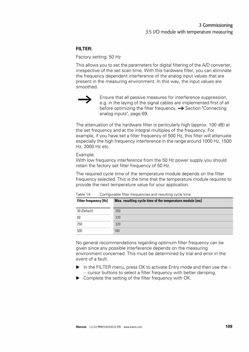
3 Commissioning
3.5 I/O module with temperature measuring
Manual 11/10 MN05002001Z-EN www.eaton.com 109
FILTER:
Factory setting: 50 Hz
This allows you to set the parameters for digital filtering of the A/D converter, irrespective of the set scan time. With this hardware filter, you can eliminate the frequency dependent interference of the analog input values that are present in the measuring environment. In this way, the input values are smoothed.
The attenuation of the hardware filter is particularly high (approx. 100 dB) at the set frequency and at the integral multiples of the frequency. For example, if you have set a filter frequency of 500 Hz, this filter will attenuate especially the high frequency interference in the range around 1000 Hz, 1500 Hz, 2000 Hz etc.
Example: With low frequency interference from the 50 Hz power supply you should retain the factory set filter frequency of 50 Hz.
The required cycle time of the temperature module depends on the filter frequency selected. This is the time that the temperature module requires to provide the next temperature value for your application.
Table 14: Configurable filter frequencies and resulting cycle time
No general recommendations regarding optimum filter frequency can be given since any possible interference depends on the measuring environment concerned. This must be determined by trial and error in the event of a fault.
In the FILTER menu, press OK to activate Entry mode and then use the Í Ú cursor buttons to select a filter frequency with better damping.
Complete the setting of the filter frequency with OK.
→ Ensure that all passive measures for interference suppression, e.g. in the laying of the signal cables are implemented first of all before optimizing the filter frequency, → Section "Connecting analog inputs", page 69.
Filter frequency [Hz] Max. resulting cycle time of the temperature module [ms]
50 (Default) 350
60 370
250 320
500 160

3 Commissioning
3.5 I/O module with temperature measuring
110 Manual 11/10 MN05002001Z-EN www.eaton.com
3.5.2.2 Menu SENSOR 1 or 2This menu is used to parameterize the inputs for temperature measuring.
Figure 89: Setting options in the menu SENSOR 1
Choose menu items SENSOR 1 or SENSOR 2
• to deactivate or activate temperature measuring via the relevant sensor and
• to parameterize a scaling of the temperature values of the activated sensor.
The setting has no effect on the other sensor.
SENSOR: (ON/OFF)
Factory setting: ON
From the PARAMETERS menu choose menu item SENSOR 1 or SENSOR 2.
In the following menu, the SENSOR menu item is already selected.
Press OK to activate Entry mode and then use the Í Ú cursor buttons to switch this temperature input or off.
Complete the setting with OK.
The parameter settings described below are possible when the sensor is activated.
→ The setting options described here are the same as for the SENSOR 2 menu.
→ The factory setting of a temperature module has both sensors activated. Switch off an input that is not used, otherwise an activated but unconnected input will signal a fault such as a wire break.
GENERAL...SENSOR 1...SENSOR 2...ANALOG OUT...
SENSOR: ONOPERAND: IA01VALUES: 12 BIT (0..4095)PT1-FILTER: OFF
ONOFF
IA01MD01 - MD96
12 BIT0.1 OF 0 OF0.1 OC 1 OC
ONOFF
ONOFF

3 Commissioning
3.5 I/O module with temperature measuring
Manual 11/10 MN05002001Z-EN www.eaton.com 111
OPERAND: (IA01/02 or MD01 - 96)
Factory setting: IA01 or IA02 depending on the sensor, value range 0 - 4095.
With each temperature input you can choose between operand types IA.. and MD...
IA01/02
When assigning via the operands IA01/02 values are read in the range 0 - 4095, the resolution is approx. 2.44 mV.
MD01 - 96
If you process a temperature input via operands MD01 - 96 you can implement a scaling of the temperature values in five stages (VALUES menu).
The temperature module scales the measured temperature value to the set format and supplies a signed fixed decimal number in the relevant stage.
In the visualization you can thus display the temperature value with the decimal point and decimal places without the need for conversion in the MFD program.
How to process a temperature value via MD01 - 96:
Move to the OPERAND menu item via the SENSOR 1 or SENSOR 2 menu and select in Entry mode the operand MD01 or MD02.
Close the operand selection with OK.
You can then complete the scaling via the VALUES menu item.
VALUES
Default setting: 12 BIT (0 - 4095).
This menu item is used to scale the temperature value according to the selected temperature range. This allows you to:
• Select between degrees Celsius (°C) or Fahrenheit (°F) and • vary the resolution between 1° or 0.1° within these two display types.
→ If the input values have to be scaled, you should not implement this in the program but let the temperature module perform this task. Scaling via the program uses up cycle time and memory.
CAUTION
The scaling also affects the resolution of the read temperature value for further processing in the program. Use a high resolution if possible.

3 Commissioning
3.5 I/O module with temperature measuring
112 Manual 11/10 MN05002001Z-EN www.eaton.com
Table 15: Temperature measuring ranges and resulting value ranges with assignment via MD..
Press OK in the VALUES menu to activate Entry mode and then select unit of measure and resolution using the cursor buttons Í Ú.
Complete the scaling with OK.
The line below VALUES shows in round brackets the temperature range according to the set scale. The division of this range by the scaling factor produces the value range that you use for the parameterization in the visualization in the Value range area.
Example with selected temperature range -40°C…+90°C:
• From sensor 1 you read a temperature value via the operand MD01 and have selected a resolution of 0.1 °C under VALUES.
• The MFD shows (-40.0…90.0) as the temperature range. • In the visualization via the numerical value screen element (→ section
“6.4.15 Numerical value”, page 400) set: • Value range [min] = -400; [max] = 900 (-40.0/0.1 or 90.0/0.1).• Scaling Range: -40.0 - 90.0.
TemperatureMeasurement range
Scaling Value range(for Visualization)
For all: 12 bits 0 - 4095
-40 - 90 °C 1 °C -40 - 90
0.1 °C -400 - 900
1 °F -40 - 194
0.1 °F -400 - 1940
0 - 250 °C 1 °C 0 - 250
0.1 °C 0 - 2500
1 °F +32 - 482
0.1 °F +320 - 4820
0 - 400 °C 1 °C 0 - 400
0.1 °C 0 - 4000
1 °F +32 - 752
0.1 °F +320 - 7520
0 - 850 °C 1 °C 0 - 850
0.1 °C 0 - 8500
1 °F +32 - 1562
0.1 °F +320 - 15620
-200 - 200 °C 1 °C -200 - 200
0.1 °C -2000 - 2000
1 °F -328 - 392
0.1 °F -3280 - 3920

3 Commissioning
3.5 I/O module with temperature measuring
Manual 11/10 MN05002001Z-EN www.eaton.com 113
PT1-FILTER
Factory setting: OFF
This “software” filter with low pass or PT1 characteristics smoothes the temperature value. This suppresses variations in the temperature sensor values that are caused by high-frequency interference.
SCAN TIME
Factory setting: OFF
When the SCAN TIME is switched off, cyclical temperature measuring is deactivated. The A/D converter converts the analog input value at maximum speed.
However, if cyclical temperature measurement with equidistant scanning is required in conjunction with a DC - PID controller, switch SCAN TIME to ON .
By scanning is meant the recording of continuous analog input signals at specified intervals. The value recorded at a specific time represents the value that needs to be digitalized for the A/D converter.
After cyclical operation is activated, you can set the time interval between the individual scans via the scan time TA. The temperature module is factory set to the minimum value (200 ms).
In the example given, the scan time to be set would depend on the scan time TC of the PID controller.
In the SCAN TIME menu item: press OK to activate Entry mode and use the cursor buttons Í Ú to switch cyclical measuring on or off.
Confirm with OK.
When SCAN TIME is activated, i.e. cyclical measuring, then set the scan time TA.
In the new menu item TA: press OK to activate entry mode and use the cursor buttons ú í to move the numbers to be modified.
Use the cursor buttons Í Ú to set the value, if necessary, move to the next digit and close the parameter assignment with OK.
Exit the SENSOR menu item by pressing ESC.
→ However, the hardware filter offers the more effective filtering, see Parameterizing the filter (Hardware) (→ section “ FILTER:”, page 109).The staggered use of hardware and software filters drastically increases the recovery time. This should not, however, be greater than necessary, otherwise the signals will be delayed more than is required by the smoothing.

3 Commissioning
3.5 I/O module with temperature measuring
114 Manual 11/10 MN05002001Z-EN www.eaton.com
3.5.2.3 Menu ANALOG OUTIf you wish to output analog values, use a type MFD-TAP13 temperature module. The temperature module outputs a voltage from 0 - 10 V via the physical analog output QA1. With the fixed 12-bit conversion, the smallest resolution is approx 2.44 mV.
Figure 90: Setting options in the ANALOG OUT menu
OPERAND: (QA01 or MD01- 96)
Default settings: QA01, Value range 0 - 4095.
The analog value to be output can either be assigned to the physical analog output QA1 via the operand QA1 or via MD01 - 96 (marker double word).
QA1
When assigning via the operand QA1 values are read in the range 0 - 4095, the resolution is approx. 2.44 mV.
MD01 - 96
When assigning the analog output value via an operand MD01 - 96, you can scale it in three stages (→ VALUES menu). When the value is output and visualized at the same time, this assignment has the advantage that the temperature module already scales the output value for the required display.
Output an analog output via MD01 - MD96 as follows:
Move to the OPERAND menu item via the ANALOG OUT menu and select in Entry mode an operand MD01 - 96.
Close the operand selection with OK.
You can then complete the scaling via the VALUES menu item.
GENERAL...SENSOR 1...SENSOR 2...ANALOG OUT...
OPERAND: QA01VALUES: 12 BIT (0..4095)
QA01MD01 - MD96
12 BIT 0.1 V 0.01 V0.001 V

3 Commissioning
3.5 I/O module with temperature measuring
Manual 11/10 MN05002001Z-EN www.eaton.com 115
VALUES
Default setting: 12 BIT (0 - 4095).
Here select the 12 BIT value or the scaling of the output value in three stages between 0.001 V, 0.01 V or 0.1 V.
Table 16: Analog output values with assignment via MD..
1) limited by the 12-bit resolution
Press OK in the VALUES menu to activate Entry mode and then use the Í Ú buttons to select the scaling factor.
Complete the scaling with OK.
The scale-dependent range of the analog output values is shown in brackets in the line below VALUES. The division of this range by the scaling factor produces the value range that you use for the parameterization in the visualization in the Value range area.
Example:
• You are outputting an analog value via an MD.. operand and have selected in VALUES a resolution of 0.001 V.
• The MFD shows the range (0.000…10.000). • In the visualization via the numerical value screen element
(→ section “6.4.15 Numerical value”, page 400) set: • Value range [min] = 0; [max] = 10000 (10.00/0.001)• Scaling Range: 0.00 - 10.00
CAUTION
The scaling also affects the resolution of the analog output value. Use a high resolution if possible.
ParameterVALUES(Scaling)
Resolution [mV])
Value range(for Visualization)
12 bits 2.44 0 - 4095
0.1 V 100 0 - 100
0.01 V 10 0 - 1000
0.001 V 2.441) 0 - 10000

3 Commissioning
3.5 I/O module with temperature measuring
116 Manual 11/10 MN05002001Z-EN www.eaton.com
3.5.3 Menu DIAGNOSTICSThe temperature module offers a range of different diagnostics options that are provided separately for each sensor.
Figure 91: Setting options in the DIAGNOSTICS 1, 2
3.5.3.1 DIAGNOSTICS 1
This menu is used to control the temperature input 1. A serious fault is indicated with a tick. Temporary faults are not stored.
SHORT-CIRCUIT
Short-circuit on Sensor 1.
CABLE BREAK å
Cable break (wire break) on sensor 1.
LOWER LIMIT
The actual value on sensor 1 is below the set measuring range.
UPPER LIMIT
The actual value on sensor 1 is above the set measuring range.
3.5.4 Menu INFORMATION...
Figure 92: Menu INFORMATION
V:
(Version) operating system version of the temperature module, e.g. 1.00.
B:
(Build), the development level within the version, e.g. 0031.
DIAGNOSTICS
1...DIAGNOSTICS
2...
SHORT-CIRCUITCABLE BREAKLOWER LIMITUPPER LIMIT
→ The setting options described here are the same as for the DIAGNOSTICS 2 menu.
INFORMATION... TAP12-PT-BV: 1.00 B: 0031LAST CYCLE 794 mS

3 Commissioning
3.6 Configuring the analog expansion unit
Manual 11/10 MN05002001Z-EN www.eaton.com 117
LAST CYCLE: [ms]
The time which the temperature module required for measuring, converting and possibly filtering and scaling the last measured value, e.g. 393 ms. A filter can considerably increase the cycle time.
When SCAN TIME is deactivated the displayed cycle time is determined by the stated factors.
With cyclical temperature measuring (SCAN TIME = ON), the cycle time is primarily determined by the set scan time TA, → section “ SCAN TIME”, page 113.
The cycle time output here indicates whether the temperature module can provide the measured value within the SCAN TIME set.
3.5.5 NEW PARAMETERS...!SAVE:
This menu appears after a parameter change.
Press OK pushbutton to confirm or discard your entries by leaving the menu with CANCEL.
3.6 Configuring the analog expansion unitThe EASY4..-DC-ME expansion units for analog value and temperature measuring must be configured before commissioning. The digital inputs/outputs of these expansion units are detected by the basic device automatically - without any configuration.
You can carry out the configuration conveniently with easySoft-Pro or via the buttons on the display/HMI unit.
Basic requirements:
• The MFD basic device and the expansion unit are connected via the EASY-LINK-DS plug connector.
• Both devices must be connected to the power supply and mounted.• The basic device must be in STOP mode and the Status display must be
showing.
All analog inputs and outputs of this expansion unit can be activated/deactivated individually.
They are processed in the program using marker words, → Table 17.
Carry out the parameter and configuration settings for an analog expansion unit in the IO-DEVICE MODE- INPUT XXXX menu:
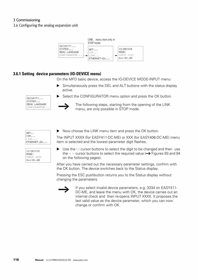
3 Commissioning
3.6 Configuring the analog expansion unit
118 Manual 11/10 MN05002001Z-EN www.eaton.com
3.6.1 Setting device parameters (IO-DEVICE menu)On the MFD basic device, access the IO-DEVICE MODE-INPUT menu:
Simultaneously press the DEL and ALT buttons with the status display active.
Select the CONFIGURATOR menu option and press the OK button.
Now choose the LINK menu item and press the OK button.
The INPUT XXXX (for EASY411-DC-ME) or XXX (for EASY406-DC-ME) menu item is selected and the lowest parameter digit flashes.
Use the ú í cursor buttons to select the digit to be changed and then use the Í Ú cursor buttons to select the required value (→ Figures 93 and 94 on the following pages).
After you have carried out the necessary parameter settings, confirm with the OK button. The device switches back to the Status display.
Pressing the ESC pushbutton returns you to the Status display without changing the parameters.
SECURITY...
SYSTEM...
MENU LANGUAGE
CONFIGURATOR...
NET...
COM...
LINK...
ETHERNET-GW...
LINK... menu item only in STOP mode.
IO-DEVICE MODE-
INPUT XXXX
4xx-01.00
SECURITY...
SYSTEM...
MENU LANGUAGE
CONFIGURATOR... → The following steps, starting from the opening of the LINK menu, are only possible in STOP mode.
NET..
COM...
LINK...
ETHERNET_GW...
IO-DEVICE
MODE-
INPUT 3333
4xx-01.00
→ If you select invalid device parameters, e.g. 3334 on EASY411-DC-ME, and leave the menu with OK, the device carries out an internal check and then re-opens INPUT XXXX. It proposes the last valid value as the device parameter, which you can now change or confirm with OK.

3 Commissioning
3.6 Configuring the analog expansion unit
Manual 11/10 MN05002001Z-EN www.eaton.com 119
Figure 93: Device parameters EASY406-DC-ME (three-digit)
Factory setting = 111(analog input 1 and 2 are activated, both for 0 - 10 V as well as the analog output). Marker words MW93 - MW95 are therefore assigned (→ Table 17, page 120).
With EASY406-DC-ME you can activate and commission a voltage, current or temperature input for analog value 1 and 2.
Figure 94: Device parameters EASY411-DC-ME (four-digit number)
Factory setting = 3333(analog input 1 to 6 are activated, as well as analog output 1 and 2). Marker words MW89 - MW96 are therefore assigned (→ Table 17, page 120).
With EASY411-DC-ME you can activate and commission all six analog inputs (voltage, current or temperature) at the same time.
X X X
X: 1. Analog input:0 = off 1 = 0 - 10 V 2 = 0 - 20 mA 3 = PT100 resistance sensor
X: 2. Analog input0 = off 1 = 0 - 10 V 2 = 0 - 20 mA 3 = PT100 resistance sensor
X: Analog output:0 = off 1 = ON
X X X X
X: 0 - 10 V, 1. und 4. analog input:0 = both off 1 = 1. analog input on2 = 4. analog input on3 = 1 + 4. analog input on
X: 0 - 20 mA, 2. und 5. analog input:0 = both off1 = 2. analog input on2 = 5. analog input on3 = 2. + 5. analog input on
X: PT100 resistance sensor, 3. und 6. input:0 = both off1 = 3. analog input on2 = 6. analog input on3 = 3. + 6. analog input on
X: 1. und 2. analog output:0 = both off1 = 1. analog output on2 = 2. analog output on3 = 1. + 2. analog output on

3 Commissioning
3.6 Configuring the analog expansion unit
120 Manual 11/10 MN05002001Z-EN www.eaton.com
3.6.1.1 Temperature measurementThe analog expansion units operate with connected Pt100 sensors in a range between -50 °C and 200 °C.
3.6.2 Processing analog input/output valuesYou access the configured analog input/output values via marker words (MW). The process image is located in the marker words.
3.6.2.1 Marker assignment with operation on MFD basic devices
Table 17: Marker assignment using analog input/output values
→ The device parameters configured here are stored retentively and exclusively in the expansion device, but not in the basic unit.Consequence: when replacing a configured expansion device, this configuration must be repeated
Analog value Input/Output
EASY406-DC-ME EASY411-DC-ME
1. Analog input MW93 MW89
2. Analog input MW94 MW91
3. Analog input – MW93
4. Analog input – MW90
5. Analog input – MW92
6. Analog input – MW94
1. Analog output MW95 MW95
2. Analog output – MW96
→ A new analog expansion unit is factory set for all inputs/outputs to be activated. All the assigned marker words are thus also taken.For your expansion unit only configure the analog inputs/outputs that are actually required. This has several advantages:• More free marker words for use in the program or in the
visualization.• Only relevant error messages, as otherwise an activated but
unconnected input will signal a fault such as a wire breakage.
• Shorter response times due to faster data exchange between basic device and expansion unit.
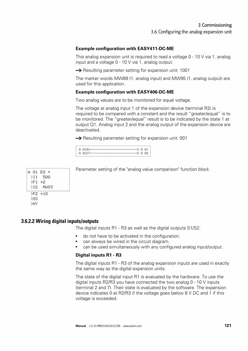
3 Commissioning
3.6 Configuring the analog expansion unit
Manual 11/10 MN05002001Z-EN www.eaton.com 121
Example configuration with EASY411-DC-ME
This analog expansion unit is required to read a voltage 0 - 10 V via 1. analog input and a voltage 0 - 10 V via 1. analog output.
→ Resulting parameter setting for expansion unit: 1001
The marker words MW89 (1. analog input) and MW95 (1. analog output) are used for this application.
Example configuration with EASY406-DC-ME
Two analog values are to be monitored for equal voltage.
The voltage at analog input 1 of the expansion device (terminal R2) is required to be compared with a constant and the result “greater/equal” is to be monitored. The “greater/equal” result is to be indicated by the state 1 at output Q1. Analog input 2 and the analog output of the expansion device are deactivated.
→ Resulting parameter setting for expansion unit: 001
Parameter setting of the "analog value comparison" function block
3.6.2.2 Wiring digital inputs/outputsThe digital inputs R1 - R3 as well as the digital outputs S1/S2:
• do not have to be activated in the configuration.• can always be wired in the circuit diagram.• can be used simultaneously with any configured analog input/output.
Digital inputs R1 - R3
The digital inputs R1 - R3 of the analog expansion inputs are used in exactly the same way as the digital expansion units.
The state of the digital input R1 is evaluated by the hardware. To use the digital inputs R2/R3 you have connected the two analog 0 - 10 V inputs (terminal 2 and 7). Their state is evaluated by the software. The expansion device indicates 0 at R2/R3 if the voltage goes below 8 V DC and 1 if this voltage is exceeded.
A 01Q1-------------------------Ä Q 01 A 01CY-------------------------S Q 02
A 01 EQ +
>I1 500
>F1 +2
>I2 MW93
>F2 +10
>OS
>HY

3 Commissioning
3.7 Commissioning NET stations
122 Manual 11/10 MN05002001Z-EN www.eaton.com
Digital outputs S1, S2
The digital outputs S1 and S2 of the analog expansion units are used in exactly the same way as the digital expansion units.
3.6.3 Diagnostics of an analog expansion unit
Table 18: Group fault messages of the analog expansion units
3.7 Commissioning NET stationsRequirements for commissioning the NET:
• All stations must be properly connected to the NET (→ Section "2.7 Connecting the NET network“, page 82), the bus terminating resistors on the physically first and last NET stations must be fitted and the supply voltage must be connected to all NET stations. The POW LED of all NET stations must be lit or flashing.
• Ideally use a device with a display or display and keypad as the first NET station.
• The device to be parameterized must be in STOP mode. The POW LED of this NET station must be permanently lit.
When commissioning for the first time, the NET LED is “Off”.
Diagnostics contact
Fault on 1 state
Meaning of group message
(with identical measuring processes, the same fault can be present at two analog inputs or outputs).
R13 Wire break on at least one analog input for measuring 4 - 20 mA current. With current measuring activated the fault message can only appear if a current < 3 mA is present.
R14 Wire break on at least one PT100 input for temperature measuring.The fault message can only appear with PT100 measuring activated.
R15 Short-circuit at analog output 0 - 10 V.
R16 Short-circuit on at least one digital output
→ Your NET can only be configured by the station with NET-ID 1 if it has been set up according to the "loop-through" (→ Page 85) topology. In order to simplify the process, you should define all parameters through this NET station with NET-ID 1.

3 Commissioning
3.7 Commissioning NET stations
Manual 11/10 MN05002001Z-EN www.eaton.com 123
Figure 95: Example topology with two NET stations
a Bus termination resistor
physical location station number
3.7.1 NET parameterizeIf you wish to work with the non-safety NET and exchange non-safety data with several stations, you must complete the parameterization and configuration for this beforehand.
An introduction to the easyNet network is provided in → section “7.1 Introduction network Net”, page 437.
2
1
1
2
I1 – I12
Q1 – Q6
R1 – R12
S1 – S8

3 Commissioning
3.7 Commissioning NET stations
124 Manual 11/10 MN05002001Z-EN www.eaton.com
3.7.1.1 Quick entry
You can assign parameters and complete the configuration conveniently with easySoft-Pro or via the buttons of a device with display. A detailed description of the NET parameters is provided in (→ section “7.2 Description of the NET-PARAMETERs”, page 440).
"Creating the station list" (STATION menu)→ Page 126
no
Parameterize each NET station individually.
no
Ye
Ye
Topology ”Passing through“?
NET-ID = 1?
NET Station with circuit diagram?
"Checking the functionality of the NET", → Page 479
Yes
no
NET parameterize
Commissioning NET stations
"Configuring NET" (CONFIGURATOR menu)
→ Page 127
"Wiring NET operands in the circuit diagram" → Page 179
Operate NET stations 2 to 8 as remote IO without a circuit diagram, → Page 443

3 Commissioning
3.7 Commissioning NET stations
Manual 11/10 MN05002001Z-EN www.eaton.com 125
Parameter setting
Carry out the parameter and configuration settings of a NET station in the NET PARAMETERS menu:
Figure 96: Menu NET PARAMETERS
On the MFD device with a network connection (MFD-...-NT) enter the NET PARAMETERS menu as follows:
Simultaneously press the DEL and ALT buttons with the status display active.
Select the CONFIGURATOR menu option and press the OK button.
Select the NET menu option and press the OK button.
Select the NET PARAMETERS menu option and press the OK button.
Use the Í and Ú buttons to assign the NET ID (in this case: NET ID 01) in the NET PARAMETERS menu and confirm the setting with OK.
Move to the baud rate and set here the maximum permissible transfer rate that your NET allows (→ section “11.3.8 NET network”, page 515). This will save you any unnecessary delay times:
The remaining parameters are not described further here. They are described in detail (→ section “7.2 Description of the NET-PARAMETERs”, page 440).
→ Start the parameterisation with the physically first device on the NET, the station with NET ID 1. This NET station can be used to configure the entire NET. You should only configure the device locally when you are replacing individual devices.
NET ID : 01
BAUD RATE:1000KB
BUS DELAY: 00
SEND IO:
PROTECTION...
SYSTEM...
MENU LANGUAGE
CONFIGURATOR... NET...
LINK...
Display NET only in STOP mode.
NET
PARAMETERS...
STATIONS...
CONFIGURE
SECURITY...
SYSTEM...
MENU LANGUAGE
CONFIGURATOR... → The following steps, starting from the opening of the NET menu, are only possible in STOP mode.
NET..
COM...
LINK...
ETHERNET_GW...
NET
PARAMETERS...
STATIONS...
CONFIGURE...
NET ID : 01 ÆBAUD RATE:125KB
BUS DELAY: 00
SEND IO å æREMOTE RUN å

3 Commissioning
3.7 Commissioning NET stations
126 Manual 11/10 MN05002001Z-EN www.eaton.com
If all settings are ok, press ESC to exit the menu.As you are currently parameterizing the station with NET ID 1, you can now create the NET station list in the STATION menu, then assign the NET IDs via the CONFIGURATION menu and set a standard baud rate and bus delay time.
3.7.1.2 Creating the station listYou create the station list in the STATION menu.
Only the physically first station with NET ID 1 manages a station list. You can only register other NET stations via this NET station or via easySoft-Pro.
Figure 97: STATION menu
Use the Í and Ú cursor buttons to select the STATION... menu and press the OK button.
Proceed to the station with physical address 2.
Select the required physical location, in this case position 2, with the Í and Ú cursor buttons and press OK.
Select the NET ID 2 with the Í and Ú cursor buttons and confirm your input with the OK button.
At physical location 2, the station has been assigned station address 2.
Press ESC to return to the STATIONS menu item.
→ The functions REMOTE RUN and REMOTE IO are not required for the station with NET ID 1 and are therefore not available here.
NET
PARAMETERS...
STATIONS...
CONFIGURE
This list is only created in station 1 (station with NET ID 1).
SAVE Æ æ
CANCEL Æ æ
POS NET ID Æ1 1
2 0
3 0 æ4 0
5 0
6 0
7 0
8 0
PROTECTION...
SYSTEM...
MENU LANGUAGE
CONFIGURATOR...NET...
LINK...
Display NET only in STOP mode.
NET-PARAMETER...STATIONS...
CONFIGURE...
1 1 Æ2 0
3 0
4 0 æ → The left-hand column shows the geographical position of the device on the network. Use the number in the right-hand column to assign a NET ID to the device at this position. Position 1 is always assigned to NET ID 1.You can only assign unused NET IDs.
1 1 Æ2 2
3 0
4 0 æ

3 Commissioning
3.7 Commissioning NET stations
Manual 11/10 MN05002001Z-EN www.eaton.com 127
3.7.2 Configuring NETOnce you have completed the parameter assignment of the NET stations and created a station list, you can then configure the easyNet. Carry out this configuration in the CONFIGURE menu.
You can only configure the NET network by entering settings on the NET station 1.
Figure 98: CONFIGURE menu
Requirement for the configuration using NET station 1:
• You must have wired your network as a “loop through” topology. • All stations must be correctly connected to the NET and the termination
resistors must have been connected.• All stations have voltage, show the basic menu in the device display (the
status display) and are in operating mode STOP. The POW and NET LEDs must be permanently lit.
For the configuration, all devices connected on the NET are assigned their NET ID in the order in which they were entered in the station list in the STATION menu. Furthermore, all devices are automatically set with the baud rate and bus delay time set on NET station 1.
PROTECTION...
SYSTEM...
MENU LANGUAGE
CONFIGURATOR... NET...
LINK...
Display NET only in STOP mode.
NET PARAMETER...
STATIONS...
CONFIGURECONFIGURE?
CONFIGURATION
IN
PROGRESS.
Fault scenario with ID conflict.
Fault scenario with network fault.
ERR: ID CONFLICT
CONFIGURATION
OVERWRITE ?
ERR: TIME OUT

3 Commissioning
3.7 Commissioning NET stations
128 Manual 11/10 MN05002001Z-EN www.eaton.com
3.7.2.1 Procedure Proceed to the CONFIGURE menu item and press the OK button.
You will be asked to acknowledge whether you want to configure the system.
Press OK.
The configuration is successfully completed if the message on the left appears. The NET menu is displayed again and the NET LEDs of all stations flash. The NET is operational.
Press the ESC key to exit the menu.
CAUTION
The REMOTE IO, SEND IO and REMOTE RUN parameters required for operation are not transferred to the connected device with the NET configuration. If you require a parameter setting that is different to the factory setting, you can do this locally via the NET PARAMETERS menu of the NET station concerned. An easier way is to carry out the parameter setting in easySoft-Pro in conjunction with a program transfer to the device concerned.
→ During the NET configuration, all connected stations switch automatically to the operating state STOP. The NET LED for the stations with NET ID 2-8 switches to OFF.
NET-PARAMETER...STATIONS...
CONFIGURE
CONFIGURE?
CONFIGURATION
IN
PROGRESS.
→ Any errors during the configuration are indicated by messages or via the NET LEDs.Further information can be found in following section and → section “10.4 Functionality of the NET faulty”, page 489.

3 Commissioning
3.7 Commissioning NET stations
Manual 11/10 MN05002001Z-EN www.eaton.com 129
3.7.2.2 MessagesThe following messages may be output during the configuration:
Table 19: Possible messages during the configuration
Error message: ID conflict
An error message will appear if a station has a NET ID that does not correspond to the physical location in the station list:
If you wish to correct the NET ID ( → Section "3.7.3.2 Changing NET ID and position“), confirm the prompt with OK. Otherwise you can cancel the configuration with ESC.
3.7.3 Changing the NET configurationThe configuration of the NET network can be modified at any time at NET station 1, physical location 1.
3.7.3.1 Changing NET PARAMETERS The NET parameters are modified (→ section “3.7.1 NET parameterize”,
page 123).
3.7.3.2 Changing NET ID and position Go to the physical location which is to be modified (→ Section
"3.7.1.2 Creating the station list“ on page 126). Press the OK button.
Message Meaning
CONFIGURATION
IN
PROGRESS.
The configuration is error-free, the NET is then operational with the connected stations.
ERR: ID CONFLICT
CONFIGURATION
CONFIGURATION ?
At least two NET stations have the same NET ID → Section " Error message: ID conflict“.
ERR: TIME OUT Network fault, for example if the cable is not correctly fitted or interrupted. Or you are trying to assign NET ID 1 to a NET station, although a master with NET ID 1 is already present on the NET. Solution: Check the plug connection or the assigned NET IDs and restart the configuration.
ERR: ID CONFLICT
CONFIGURATION
OVERWRITE ?
→ Existing NET IDs can only be modified to free, non-assigned NET IDs. If all eight numbers are assigned, all NET IDs which are to be modified must be set to zero. After that all NET IDs can be reassigned.For greater simplicity, the device sets all NET IDs to zero that have a physical location behind the first assigned zero.

3 Commissioning
3.7 Commissioning NET stations
130 Manual 11/10 MN05002001Z-EN www.eaton.com
Select the required NET ID with the Í and Ú cursor buttons and confirm your input with the OK button.
Configure NET stations again using the CONFIGURATION menu, → section “3.7.2.1 Procedure”, page 128.
If your NET configuration does not function as required you will find a description of possible causes in → section “10.4 Functionality of the NET faulty”, page 489
3.7.3.3 Deleting the program of a NET stationSelecting DELETE PROGRAM on a configured NET station will also delete its NET ID.
The device concerned is no longer a NET station, indicated by its switched off LED. The NET LED of all other configured NET stations in operation indicates the NET fault with a "permanent light".
CAUTION
Operating the NET with two masters (two stations with NET-ID 1) is not allowed, and leads to malfunctions on the NET. Possible effects of this type of incorrect configuration with two masters competing against each other, and in which one is operated in the STOP operating mode and the other in the RUN operating mode, are as follows:NET stations with NET-ID 2 - 8 that should follow the operating mode changes of the NET station with NET-ID 1 automatically during operation (REMOTE RUN parametric programming) keep toggling constantly between the STOP and RUN operating states. When integrating a master that is already configured into an existing NET, please make sure that there is no other station with NET-ID 1 on the NET.Also, when performing the configuration from easySoft-Pro and a local connection to a station, please make sure you do not assign NET-ID 1 to this station if there is a master on the NET already.Tip: Carry out a NET configuration through NET station 1 after every change to the NET.
CAUTION
If you delete the program in NET station 1, the NET configuration managed by this station is also deleted.

3 Commissioning
3.7 Commissioning NET stations
Manual 11/10 MN05002001Z-EN www.eaton.com 131
Solution for the accidental deletion of the NET configuration
• With “loop-through” topologyYou must create a new NET configuration via the NET station 1 (→ section “3.7.2 Configuring NET”, page 127).
• With “T-piece and spur line” topology.Locally reassign a NET ID to the device concerned.
3.7.4 Showing the status display of other NET stationsOn each device with a program and a display with operating buttons, you display the status of the inputs and outputs of every other NET station.
For this change to the status display and press the ESC button.
The cursor switches to the display of NET station NT1 and flashes. The NET ID precedes the display of the input/output ID (e.g. 1I..).
Change the number of the required NET station with the Í and Ú cursor buttons.
The input/output states of this NET station are shown in the display (e.g. 3I../3Q..).
Press the ALT button several times if you wish to see the locally set time, the date or the group fault alarms for transistor outputs on this NET station.
Pressing the ESC button further will terminate the display of the input and output states of this NET station and will activate the local display of NET station NT1.
Example: You are viewing the display of NET station NT3, and NT3 is flashing in the display. The inputs and outputs 3I.., 3R.., 3Q.. and 3S.. cannot be displayed.
After you have switched to the local display by pressing ESC, the NT3 display is no longer flashing and the states of the local inputs and outputs are displayed.
1I12..........
NT1
MO 06:42
1Q1....... RUN
3I12.....7....
NT3
MO 06:42
3Q1.3..6.. RUN
3R12.....7....
NT3
MO 06:45
3S1.3..6.. RUN
→ The NET station that shows the status on its display, cannot read out its own data from the NET (see the following example).

3 Commissioning
3.8 COM-LINK connection
132 Manual 11/10 MN05002001Z-EN www.eaton.com
3.8 COM-LINK connection
3.8.1 General information on COM-LINKCOM-LINK is a connection between an MFD and an easy800, easySafety or another MFD device. This connection is called a “COM connection” in easySoft-Pro. It requires one active station which can only be an MFD and one passive remote station.The active station controls the data exchange of COM-LINK operands with the remote station. This responds only to the requests of the active station. The active station can • read the status of the inputs/outputs on the remote station.• read or write the marker range MD01 - MD20 on the remote station.
This data can be used in the active MFD for setpoint definition or display functions.
Figure 99: COM-LINK connection to an easy800, easySafety or another MFD
If you connect two MFD devices with each other, only one device must be the active station, i.e. COM-LINK must only be activated once in the COM menu.
An MFD operating as an active station in the COM-LINK network cannot be an easyNet station at the same time. A passive station on the COM-LINK can however also be an easyNet station at the same time. If an MFD station is run as an easyNet station, it can therefore only be used as a passive remote station.
→ Time-critical processes should not be controlled using this connection.
POW-Side

3 Commissioning
3.8 COM-LINK connection
Manual 11/10 MN05002001Z-EN www.eaton.com 133
3.8.2 Configuring the interface for COM-LINKThe physical interface for the COM-LINK connection is the serial multi-function interface. To activate the COM-LINK connection, the following settings must be known to the active station:
• Baud Rate• COM-LINK (active)• Remote marker range (data exchange range).
Connect both devices using an MFD-800-CAB5 cable.
Only use the original connecting cable. The connector marked “POW-Side” must be plugged into an MFD which supplies the interface circuit in the connecting cable.
Connect the power supply to both stations and switch it on.
To operate the COM-LINK connection, only the interface and the marker range of the access data have to be parameterized on the active device. To configure the interface, select the baud rate and activate the COM-LINK connection. This can be carried out via the display/keypad of the MFD.
WARNING
If the MFD station is on the easyNet and you switch on the COM-LINK during operation, the easyNet network is deactivated. No further data is exchanged.Remedy: Deactivate the COM-LINK connection. Reenter the station address. Switch the power supply off and then on again. Configure the easyNet.
→ The following steps are only possible in STOP mode.

3 Commissioning
3.8 COM-LINK connection
134 Manual 11/10 MN05002001Z-EN www.eaton.com
3.8.2.1 Baud rate adjustment Simultaneously press the DEL and ALT buttons with the Status display
active.
The System menu appears.
Choose the CONFIGURATOR menu item and press the OK button.
Choose the COM menu item and press the OK button.
The menu BAUDRATE: 9600B will appear. The two baud rates are for 9600 or 19200 baud.
Select 19200 baud and confirm with OK.
3.8.2.2 activate COM-LINK
Press the Ú pushbutton. Press the OK button.
The tick on the COM-LINK menu item indicates that the connection is activated.
SECURITY...
SYSTEM...
MENU LANGUAGE
CONFIGURATOR...
NET..
COM...
LINK...
ETHERNET-GW...
BAUDRATE: 9600B
COM-LINK
REMOTE MARKER..
BAUD RATE: 19200
B
COM-LINK
REMOTE MARKER...→ If faults occur, change the baud rate to 9600. Check the
connection cable. The routing of the cable can help to rectify the faults.
→ The COM-LINK connection must only be activated on the active station.
BAUD RATE:
19200 B
COM-LINK åREMOTE MARKER..

3 Commissioning
3.8 COM-LINK connection
Manual 11/10 MN05002001Z-EN www.eaton.com 135
3.8.2.3 Remote Specifying the marker range Select the REMOTE MARKER menu item.
The following selection is displayed only if COM-LINK is activated.
Press the OK button.
The display indicates the READ and WRITE range with default markers (double words).
Press the OK button. Use the Í pushbutton to select the beginning of the READ marker range. Use the í pushbutton to enter the upper limit of the READ range. Use the Í pushbutton to select the value. Confirm the entry with the OK pushbutton.
Use the Ú button to enter the WRITE range. Enter the WRITE range.
Press ESC pushbutton to leave the entry menu.
Press ESC to return to the Status display.
The entry in the second COM line indicates that the COM-LINK connection is active.
The COM-LINK has now been set.
Wiring COM-LINK operands in the circuit diagram, → section “4.8 Wiring COM-LINK operands in the circuit diagram”, page 184.
Monitoring the COM-LINK connection → section “9.6 Monitoring the COM-LINK connection”, page 483
BAUD RATE:
19200 B
COM-LINK åREMOTE MARKER..
READ:
1MD00 Ç 1MD00WRITE:
1MD00 Ç 1MD00
READ:
1MD11 Ç 1MD14WRITE:
1MD00 Ç 1MD00
READ:
1MD11 Ç 1MD14WRITE:
1MD00 Ç 1MD00
READ:
1MD11 Ç 1MD14WRITE:
1MD15 Ç 1MD17
BAUD RATE:
19200 B
COM-LINK åREMOTE MARKER..
I 12.4.67.....
I COM
P-
FR 02:02 ST
→ The COM-LINK connection must not be configured on the remote station.

3 Commissioning
3.9 Running MFD in Terminal mode
136 Manual 11/10 MN05002001Z-EN www.eaton.com
3.9 Running MFD in Terminal mode
An MFD in Terminal mode allows you to remotely operate, i.e. read and control, other devices, such as easy500/700 and easy800 control relays, MFD or ES4P.. safety control relays.
Once this controlling MFD has established a connection to the target station, the display of this station is transferred and continuously refreshed. If the target station is a device without a display, e.g. EASY8..-..-.. X, the actual data and states are shown in a simulated display on the controlling MFD.
You can carry out the same functions on the keypad of the controlling MFD as on the keypad of the local target station.
This application mode for a permanent remote display device is particularly useful for operating devices that do not have a display or which are difficult to access, which do not allow direct operation in the field.
You can set the MFD to switch to TERMINAL MODE on power up and establish a connection to the defined station.→ Section "8.2.4 TERMINAL MODE startup (TERMINAL MODE menu item)“.
You connect the controlling MFD in two ways:
• via the multi-function interface in a point-to-point connection to a single device.
• as a NET station via the easyNet (NET) to another NET station.
The controlling MFD does not require a program for Terminal mode, but can run a program after switching from TERMINAL MODE to RUN mode.
Table 20: Meaning of the front LED display of the MFD in Terminal mode
→ A terminal connection can be set up to an easy800 device with device version number 04 or higher.
LED Health Meaning
Red Off Fault-free NET operation
Red continuous light
The remotely controlled device is NET station and its network connection is interrupted, or the NET configuration was changed, but not yet transferred to the device network.
Green Off The remotely controlled device is without a power supply. The local display indicates that the connection has broken.
Green continuous light
The remotely controlled device is in STOP mode.
Green Flashing The remote device is in RUN mode.

3 Commissioning
3.9 Running MFD in Terminal mode
Manual 11/10 MN05002001Z-EN www.eaton.com 137
3.9.1 MFD as a station of a point-to-point connectionSet up a terminal connection to the single device via the point-to-point connection.
The following description shows the example of a point-to-point connection to an easy800.
Figure 100: MFD - easy800 connection
Requirements for connection:
• The COM-LINK connection on the MFD must be inactive.• The controlling MFD is in STOP mode. • Both devices must be connected via the MFD-800-CAB5 cable.
Switch the MFD to Terminal mode in the following way:
Press OK to move from the Status display to the main menu. Select the TERMINAL MODE and confirm the selection with OK. For a point-to-point connection choose 0 as STATION ID. Choose the START MODE menu item and press the OK button.
The MFD display now shows the content of the easy800 display. To indicate that the MFD is in Terminal mode the star * flashes in the top right corner of the Status display.
Pressing the Mode pushbutton (*) on the controlling MFD returns you back to its local Status display.
→ Ensure that the plug marked POW-Side is fitted in the multi-function interface of the active (controlling) MFD. The serial interface only functions if the MFD supplies the required power supply of the connection cable.
POW-Side
I 12..5...... *
P-
MO 11:50
Q..34.... STOP
→ Access in Terminal mode to easySafety devices is possible via a point-to-point connection. Access via the NET is not permissible and therefore inhibited.

3 Commissioning
3.9 Running MFD in Terminal mode
138 Manual 11/10 MN05002001Z-EN www.eaton.com
3.9.2 MFD as NET stationIf the controlling MFD is a NET station itself, you can establish a direct Terminal connection in succession to every other NET station.
If you use an MFD device from device version number 05 you can also set up an indirect terminal connection (→ Figure 103, page 139).
3.9.2.1 Direct connectionThe controlling MFD is itself a NET station. Simultaneous operation of several logical terminal connections between two NET stations is possible.
Figure 101: Access options in terminal mode
a Terminal Mode
CAUTION
Both MFD devices must not access the same NET station, e.g. the device with ID =4, at the same time. Simultaneous access via the NET by MFD in Terminal mode and the PC (programming device) to a NET station is also not possible and will cause a malfunction on the NET.
MFD-80-B MFD-CP4...
Online
easySafety
easySafety (NET-ID 6)
MFD-...-NT
MFD-...-NTeasy800
easy800 (NET-ID 1)
PC
easySoft-Pro easySoft-Safety
a
a
6
5 4
1
2
3

3 Commissioning
3.9 Running MFD in Terminal mode
Manual 11/10 MN05002001Z-EN www.eaton.com 139
Figure 102: Terminal connection to a different NET station
Select the TERMINAL MODE and confirm the selection with OK. As STATION ID select the NET-ID of the required station. Start the terminal mode as described.
3.9.2.2 Indirect connectionThe controlling MFD is connected via the multi-function interface with a NET station serving as a base station. In Terminal mode you can select another NET station (target station) via the base station and also check or change its status.
Figure 103: Indirect Terminal connection
Requirements for connection:
• The COM-LINK connection on the MFD must be inactive.• The controlling MFD must be in STOP operating mode and both devices
must be connected via the MFD-800-CAB5 cable.
Select the TERMINAL MODE and confirm the selection with OK. As STATION ID select the NET-ID of the required station. Start the terminal mode as described.
logical connection Access permitted/not permitted
Explanation
1 + 2, 1 + 4 Not permissible Simultaneous access to a NET station from 2 sides
2 +3 Not possible In terminal mode, the display/operator system establishes only one logical connection at a time
5 Not permissible Terminal mode via the NET to easySafety
1 + 3, 3 + 4 Permissible Simultaneous operation of several terminal connections to different stations
6 Permissible Local terminal operation to a device that is also a NET station
1, 2, 3, 4 Permissible Local terminal operation to one device in each case
Net ID 1 Net ID 2 Net ID 3 Net ID 8
easy800easy800easy800 MFD
easyNet
Net ID 1 Net ID 2 Net ID 3 Net ID 8
easy800easy800easy800easy800
MFD COM-LINK
easyNet

3 Commissioning
3.9 Running MFD in Terminal mode
140 Manual 11/10 MN05002001Z-EN www.eaton.com
3.9.2.3 Example 1: MFD as a NET stationThe controlling MFD can be used at any location on the NET. The Terminal mode functions independently of the location and NET ID (1 - 8) of the device.
Figure 104: MFD on easyNET
Establishing a connection to NET stations 1…8
Requirement for connection:
• The COM-LINK connection is not active.• The controlling MFD is not in the STOP state.
Procedure:
Press the OK pushbutton from the Status Display.The menu appears.
Press the Í pushbutton.
The TERMINAL MODE menu item flashes.
Press the OK button.
→ In this configuration, an MFD cannot access a safety control relay on the network.
1 1
2 51 2
1 2
I 1 - 12
Q 1 - 6
3 7 AS-Interface
+ –
4 3
I 1 - 12
Q 1 - 8
R 1 - 12
S 1 - 6
R 1 - 12
MFD
S 1 - 8
1 2I 1 - 12
Q 1 - 6
PROGRAM... ÆSTOP å RUN PARAMETER
SET CLOCK...
PARAMETER ÆSET CLOCK
INFORMATION...
TERMINAL MODE…

3 Commissioning
3.9 Running MFD in Terminal mode
Manual 11/10 MN05002001Z-EN www.eaton.com 141
The START MODE text flashes.
Press the Í button.
The station ID (default value = 0) flashes.
Press the OK button.
Select the NET-ID of the station, e.g. 5: Press the Í or Ú pushbutton. Press the OK pushbutton.
Choose the START MODE menu: Press the Ú pushbutton. Press the OK button.
The MFD tries to establish connection to the selected device. The START MODE text flashes.
If the connection is established, the menu or the Status display of the selected device appears.
The easyNET station 5 controls the display of the MFD device.
Close Terminal mode
Press the * pushbutton. The MFD menu appears again for activating the Terminal mode.
STATION ID:0
START MODE
STATION ID: 0
START MODE
→ Station ID:0 = Default setting, point-to-point connection1 = station 1 on the easyNET2 = station 2 on the easyNET...8 = station 8 on easyNET
STATION ID: 0
START MODE
STATION ID: 5
START MODE
STATION ID: 5
START MODE
Connectionestablishmentin progress...
I 1..4..789...
*
I NT5 P- → The flashing star at the top right of the Status display indicates that Terminal mode is active.

3 Commissioning
3.9 Running MFD in Terminal mode
142 Manual 11/10 MN05002001Z-EN www.eaton.com
Message: No connectiona
Message: The remote device is in Graphic mode
The MFD allows a connection (Terminal mode) to be established to a target station that is also an MFD. If the target station is showing a screen in RUN mode, the controlling MFD outputs the message “Device is in Graphic mode” during connection setup.
Pressing ALT and ESC together initiates a change to the Status display, provided that the “Disable switch to Status display” button element is not activated.
3.9.2.4 Example 2: Multiple MFDs as NET stationsFigure105 includes two MFDs that are incorporated as NET stations. In Terminal mode both can access other NET stations. While the MFD (NET ID 1) accesses the device with NET ID 2, the MFD (NET ID 3) can access the device with NET ID 4 at the same time.
→ If the text “Connection establishment in progress…” is displayed for longer than 10 s, the connection to the selected device is faulty. Press ESC to cancel the selection. Rectify the fault. Try to re-establish the connection
The remote device is in Graphic mode
The remote device is in Graphic mode
→ The controlling MFD can show the status display of the target station. A screen of the target station is not shown!
WARNING
The target station connected to the MFD can be installed in an inaccessible location. Terminal mode gives you all the access rights that you would also be given "locally". Check the controlled system when you carry out a mode change and device settings.A station with a display and keypad can be operated both locally and from an external MFD. The local operation on the device is always faster than the remote operation in Terminal mode. A simultaneous input must always be avoided as this may cause malfunctions.

3 Commissioning
3.9 Running MFD in Terminal mode
Manual 11/10 MN05002001Z-EN www.eaton.com 143
Figure 105: Two MFDs in the NET
3.9.2.5 Example 3: MFD in the NET (indirect connection)Figure103 on page 139 shows an MFD connected via the serial multi-function interface to a NET station (base station). After Terminal mode is activated, you can select another NET station (target station) and check its status and states.
Requirements for connection:
• The COM-LINK connection on the MFD must not be active!• The MFD must not be a NET station (configure separately)! • The MFD must be in the STOP state.• Both devices must be connected via the MFD-800-CAB5 cable.
Switch the MFD to Terminal mode:
From this display menu select the TERMINAL MODE and confirm with OK.
Select a STATION ID 1 to 8. Select the START MODE and press OK.
The MFD display shows for example the display content of an easy800.
Press the * pushbutton to return back to the menu.
1 1
2 2
1 2
3 3
4 4
I 1 - 12
Q 1 - 8
1 2I 1 - 12
Q 1 - 6
MFD
MFD

3 Commissioning
3.9 Running MFD in Terminal mode
144 Manual 11/10 MN05002001Z-EN www.eaton.com
3.9.2.6 Example 4: Multiple MFDs in the network (indirect and direct connection)In this example, two MFDs are connected indirectly with stations of the network, and one MFD is integrated directly in the easyNet.
Figure 106: MFD devices with easyNet stations are connected directly and indirectly
→ An MFD device cannot access a station, e.g. the device with ID =2 if another MFD has already established a direct or indirect connection to this station. Simultaneous access by MFD in Terminal mode and PC (programming device) to a station is also not possible.
POW-Side
1 1
2 2
1 2
3 3
4 4
I 1 - 12
Q 1 - 8
1 2I 1 - 12
Q 1 - 6
1 2I 1 - 12
Q 1 - 6
MFD
POW-Side

4 Wiring with MFD
4.1 MFD operation
Manual 11/10 MN05002001Z-EN www.eaton.com 145
4 Wiring with MFD
This chapter describes the entire range of functions of an MFD device.
4.1 MFD operation
4.1.1 Pushbutton for editing circuit diagrams and function blocks
P buttons in square brackets [P..] are only available on the MFD-CP10...
4.1.2 OperationThe cursor buttons in the MFD circuit diagram have three functions:
• Moving.• Input.• Connecting.
The current mode is indicated by the appearance of the flashing cursor.
In “Move” mode use the ÍÚ ú í buttons to position the cursor on the circuit diagram in order to select a rung, a contact, a relay coil or the selection position of a coil function or a NET-ID.
Use OK to switch to Entry mode so that you can enter or change a value at the current cursor position. Press ESC in Entry mode to restore MFD to the last changes of an entry.
Delete rung, contact, relay or empty rung in the circuit diagram
[P7]
Toggle between N/O and N/C contactConnect contacts, relays and rungsAdd rungs
[P8]
ÍÚ
ú í
Change valueMove cursor up/downChange placeCursor left/right
Cursor buttons set as P pushbuttons:
úí Input P1,
Input P3,
ÍÚ Input P2
Input P4
Undo setting from last OK Leave current display, menu
[P6]
Change, add new contact/relay, Save setting
[P5]
Toggle for Terminal mode [P9]
DEL
ALT
ESC
OK
*
â
I 01

4 Wiring with MFD
4.2 Circuit diagram elements
146 Manual 11/10 MN05002001Z-EN www.eaton.com
Press ALT to switch to Connect mode for wiring contacts and relays. Press ALT again to return to Move.
Press ESC to exit the circuit diagram and parameter display.
4.2 Circuit diagram elements
4.2.1 ProgramA program is a series of commands that the MFD device processes cyclically in RUN operating mode.
A MFD program consists of the necessary settings for the device, easyNet, COM-LINK, password, system settings, a circuit diagram, function blocks and/or visualization screens.
The circuit diagram is the part of the program in which the contacts and coils are connected together. In RUN mode, a coil is switched on or off depending on the power flow and coil function set.
4.2.2 Function blocksFunction blocks are program blocks with special functions. Examples: Timing relays, time switch, data block comparators. Function blocks are provided with or without contacts and coils. How a safety or standard function block is added to the safety or standard circuit diagram and parameterized is described in → section “4.9 Working with function blocks”, page 188 on.
In RUN mode the function blocks are processed according to the circuit diagram and the results are updated accordingly.
Examples: Timing relay = Function block with contacts and coilsTime switch = Function block with contacts
4.2.3 Visualization screensVisualization screens are parts of the program that contain display and operating functions for the application.
l
→ The MFD device performs a large part of this cursor change automatically. For example it switches the cursor to Move mode when it is no longer possible to make an entry or connection at the selected cursor position.

4 Wiring with MFD
4.2 Circuit diagram elements
Manual 11/10 MN05002001Z-EN www.eaton.com 147
4.2.4 RelaysRelays are switching devices that are emulated in MFD device electronically, which activate their contacts according to the assigned function. A relay consists of at least one coil and contact.
4.2.5 Contacts and coils of the circuit diagram
4.2.5.1 ContactsContacts are used to change the power flow inside the MFD circuit diagram. Contacts such as N/O contacts are set to 1 when they are closed and 0 when they are opened. In the MFD circuit diagram you can wire contacts as N/O or N/C contacts. N/C contacts are indicated with a horizontal line above the operand concerned.
An MFD device operates with different contacts that you arrange in any order in the contact fields of the circuit diagram.
Table 21: Usable contacts
4.2.5.2 CoilsCoils are the actuating mechanisms of relays. The results of the wiring are transferred to the coils when the device is in RUN mode. These switch to the On (1) or Off (0) state according to these results. Coils can have seven different coil functions, → Table 27, page 174.
A MFD device is provided with different types of relays and function blocks which can be wired in a circuit diagram via their coils (inputs).
The switching of the relays is set by means of coil functions and parameters.
The options for setting output and marker relays are listed with the description of each coil function.
The coil functions and parameters for the function blocks are explained with the description of each function block.
Contact MFD representation
N/O contact, open in release position I, Q, M, A, …
N/C contact, closed in release position I, S, S, A, …
A detailed list of all contacts used in the circuit diagram is provided on page 520.
→ All coils in the circuit diagram have the "contactor" coil function!

4 Wiring with MFD
4.2 Circuit diagram elements
148 Manual 11/10 MN05002001Z-EN www.eaton.com
The following table shows a list of all contacts and coils useable in the standard circuit diagram.
Table 22: Overview of contacts and coils
Contact Coil(* = NET-ID 1-8)
Contact N/O - N/C(* = NET-ID 1-8)
Number Page
Inputs
Inputs (basic device) I.. - I/I 01–12 165
Inputs I.. (basic device) of other stations via NET - *I/*I 01–12 179
Inputs (basic device) of remote station, via COM-LINK - 1I/1I 01–12 184
Cursor buttons - P/P 01–04 172
Inputs (expansion) - R/R 01–12 165
Inputs (standard expansion) of other stations via NET - *R/*R 01–12 179
Inputs (standard expansion) of remote station, via COM-LINK - 1R/1R 01–12 184
Bit inputs via NET - *RN/*RN 01–32 179
Diagnostics inputs
Status of expansion of other station via NET - *I/*I 14 481
Short-circuit/overload on other station via NET - *I/*I 15-16 479
Status (expansion) of remote station, via COM-LINK - 1I/1I 14 186
Short-circuit/overload of other remote station via COM-LINK - 1I/1I 15-16 186
Short-circuit/overload on a expansion unit with transistor output - R/R 15-16 479
Short-circuit/overload on a expansion unit other NET stations - *R/*R 15-16 479
Short-circuit/overload with standard expansion of the remote station, via COM-LINK
- 1R/1R 15-16 186
Diagnostics messages - ID/ID 01–32 479
Diagnostics messages of remote station, via COM-LINK - 1ID/1ID 01–16 186
Outputs
Backlight of the MFD display LE - 01 420
- LE/LE
Red LED of MFD display LE - 02 23
- LE/LE
Green LED of MFD display LE - 03 23
- LE/LE
Q outputs.. (basic device) q - 01–08 165
- Q/Q
Outputs (Expansion) S - 01–08 165
- S/S
Q outputs.. (basic device) of other NET stations *Q - 01–08 179
- *Q/*Q
Outputs (expansion) of other NET stations *S - 01–08 179
- *S/*S

4 Wiring with MFD
4.2 Circuit diagram elements
Manual 11/10 MN05002001Z-EN www.eaton.com 149
Output of remote station, via COM-LINK 1Q - 01–08 186
- 1Q/1Q
Output (expansion) of remote station, via COM-LINK 1S - 01–08 186
- 1S/1S
Bit outputs via NET *SN - 01–32 179
- *SN/*SN
Other coils and contacts
Markers M - 01–96 153
- M/M
Auxiliary relay (marker or REMOTE MARKER) of remote station, via COM-LINK
1M - 01–96 154
- 1M/1M
Jump label : - 01–32 325
- :
Function Blocks
Analog value comparator 199
Value overflow (carry) - A X CY/A X CY X = 01–32
Condition fulfilled A X Q1/A X Q1
Arithmetic 204
Value overflow (carry) - AR X CY/AR X CY X = 01–32
Value zero AR X ZE/AR X ZE
Data block comparator 208
Enable BC X EN - X = 01–32
Failure: number of elements exceeded - BC X E1/BC X E1
Failure: range overlap BC X E2/BC X E2
Failure: invalid offset BC X E3/BC X E3
Comparison result BC X EQ/BC X EQ
Data block transfer 216
Activate (trigger) BT X T_ - X = 01–32
Failure: number of elements exceeded - BT X E1/BT X E1
Failure: range overlap BT X E2/BT X E2
Failure: invalid offset BT X E3/BT X E3
Boolean operation 228
Value zero - BV X ZE/BV X ZE X = 01–32
Counter 232
Contact Coil(* = NET-ID 1-8)
Contact N/O - N/C(* = NET-ID 1-8)
Number Page

4 Wiring with MFD
4.2 Circuit diagram elements
150 Manual 11/10 MN05002001Z-EN www.eaton.com
Count input C X C_ - X = 01–32
Direction C X D_
Reset count value C X RE
Set counter value (preset) C X SE
Actual value has exceeded counter range (carry) - C X CY/C X CY
Lower setpoint value undershot (Fall below) C X FB/C X FB
Upper setpoint value exceeded (overflow) C X OF/C X OF
Actual value equal to zero C X ZE/C X ZE
Frequency Counter 238
Enable counter CF X EN - X = 01–04
Lower setpoint value undershot (Fall below) - CF X FB/CF X FB
Upper setpoint value exceeded (overflow) CF X OF/CF X OF
Actual value equal to zero CF X ZE/CF X ZE
High-speed counters 243
Direction CH X D_ - X = 01–04
Enable counter CH X EN
Reset count value CH X RE
Set counter value (Preset) CH X SE
Actual value has exceeded counter range (carry) - CH X CY/CH X CY
Lower setpoint value undershot (Fall below) CH X FB/CH X FB
Upper setpoint value exceeded (overflow) CH X OF/CH X OF
Actual value equal to zero CH X ZE/CH X ZE
Incremental Encoder 249
Enable counter CI X EN - X = 01–02
Reset count value CI X RE
Set counter value (Preset) CI X SE
Actual value has exceeded counter range (carry) - CI X CY/CI X CY
Lower setpoint value undershot (Fall below) CI X FB/CI X FB
Upper setpoint value exceeded (overflow) CI X OF/CI X OF
Actual value equal to zero CI X ZE/CI X ZE
Comparison, for variables / constants 255
Equal to - CP X EQ/CP X EQ X = 01–32
Greater than CP X GT/CP X GT
Less than CP X LT/CP X LT
Data Function Block 258
Transfer 32-bit value (trigger) DB X T_ - X = 01–32
Block is active - DB X Q1/DB X Q1
PID Controller 261
Contact Coil(* = NET-ID 1-8)
Contact N/O - N/C(* = NET-ID 1-8)
Number Page
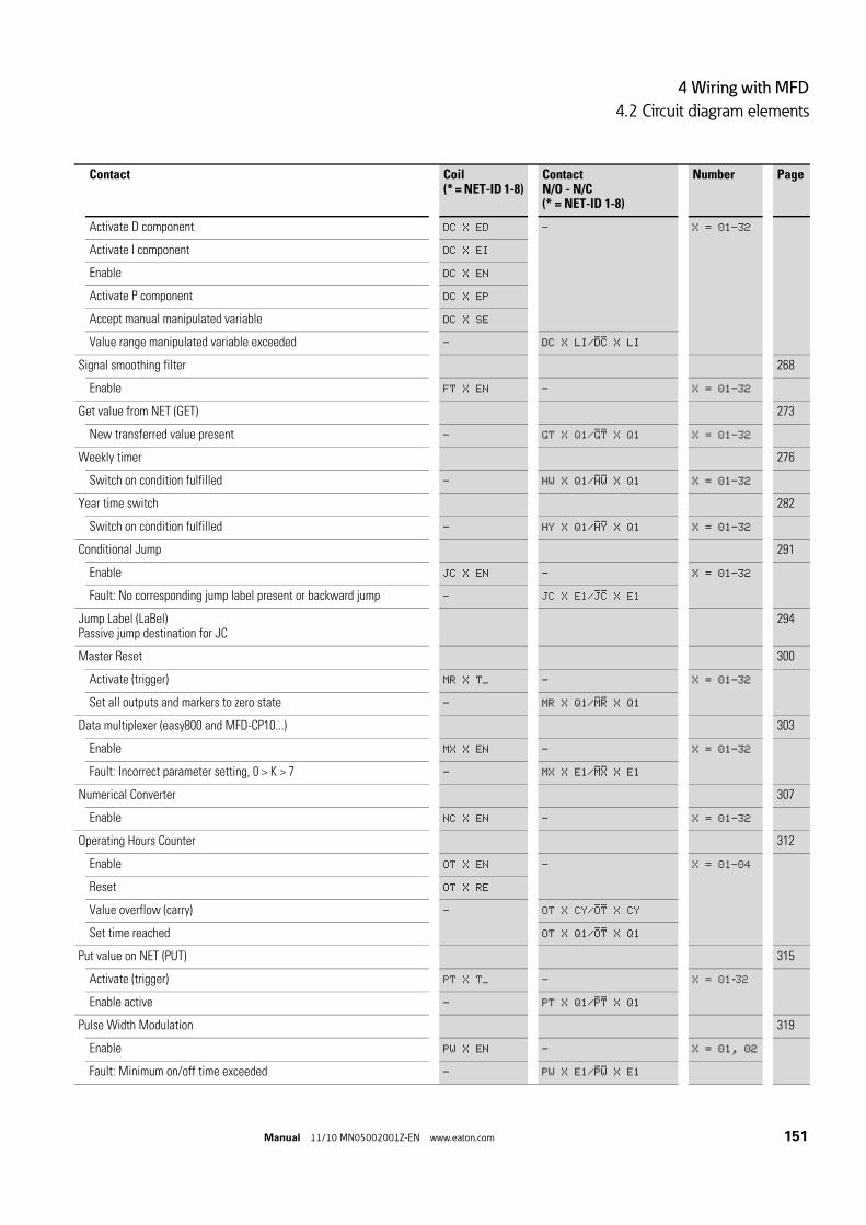
4 Wiring with MFD
4.2 Circuit diagram elements
Manual 11/10 MN05002001Z-EN www.eaton.com 151
Activate D component DC X ED - X = 01–32
Activate I component DC X EI
Enable DC X EN
Activate P component DC X EP
Accept manual manipulated variable DC X SE
Value range manipulated variable exceeded - DC X LI/DC X LI
Signal smoothing filter 268
Enable FT X EN - X = 01–32
Get value from NET (GET) 273
New transferred value present - GT X Q1/GT X Q1 X = 01–32
Weekly timer 276
Switch on condition fulfilled - HW X Q1/HW X Q1 X = 01–32
Year time switch 282
Switch on condition fulfilled - HY X Q1/HY X Q1 X = 01–32
Conditional Jump 291
Enable JC X EN - X = 01–32
Fault: No corresponding jump label present or backward jump - JC X E1/JC X E1
Jump Label (LaBel)Passive jump destination for JC
294
Master Reset 300
Activate (trigger) MR X T_ - X = 01–32
Set all outputs and markers to zero state - MR X Q1/MR X Q1
Data multiplexer (easy800 and MFD-CP10...) 303
Enable MX X EN - X = 01–32
Fault: Incorrect parameter setting, 0 > K > 7 - MX X E1/MX X E1
Numerical Converter 307
Enable NC X EN - X = 01–32
Operating Hours Counter 312
Enable OT X EN - X = 01–04
Reset OT X RE
Value overflow (carry) - OT X CY/OT X CY
Set time reached OT X Q1/OT X Q1
Put value on NET (PUT) 315
Activate (trigger) PT X T_ - X = 01-32
Enable active - PT X Q1/PT X Q1
Pulse Width Modulation 319
Enable PW X EN - X = 01, 02
Fault: Minimum on/off time exceeded - PW X E1/PW X E1
Contact Coil(* = NET-ID 1-8)
Contact N/O - N/C(* = NET-ID 1-8)
Number Page

4 Wiring with MFD
4.2 Circuit diagram elements
152 Manual 11/10 MN05002001Z-EN www.eaton.com
A list with an overview of the function blocks and a brief description of function block coils and contacts is provided at → Section "11.4 List of function blocks“ on page 458.
4.2.6 Markers and analog operandsThe term “Marker” generally refers to the standard marker bit (M), also called auxiliary relay. MFD devices also process marker bytes (MB), marker words (MW) and marker double words (MD). Markers are used in the appropriate format for the intermediate storage of data. The marker bits (M) are used accordingly to store Boolean states 0 or 1.
You can use marker bits (M), marker bytes (MB), marker words (MW) and marker double words (MD) in the circuit diagram and function block diagram as well as in the visualization.
Synchronize clock via NET (Set clock) 323
Trigger SC X T_ SC X T_ X = 01
Trigger acknowledgement SC X Q1
SC X Q1SC X Q1/SC X Q1
Shift Register 325
Enable SR X EN - X = 01–32
Shift Register - SR X Q1-8/SR X Q1-8
Set Cycle Time 337
Enable ST X EN - X = 01
Timing Relay 340
Enable T X EN - X = 01-32
Timing relay reset T X RE
Timing relay Stop T X ST
Timing Relay-Switching contact - T X Q1/T X Q1
Table Function 350
Enable TB X EN - X = 01-32
Table empty - TB X TE/TB X TE
Table full TB X TF/TB X TF
Value Limit 355
Enable VC X EN - X = 01–32
Contact Coil(* = NET-ID 1-8)
Contact N/O - N/C(* = NET-ID 1-8)
Number Page

4 Wiring with MFD
4.2 Circuit diagram elements
Manual 11/10 MN05002001Z-EN www.eaton.com 153
Table 23: Markers and analog operands
An MFD enables you to access specific operands of the remote station by means of a point-to-point serial connection called COM-LINK. These COM-LINK operands are identified by means of the preceding station number 1. The following table shows you the access to remote markers that can be set on the MFD via the System menu -> CONFIGURATOR -> COM... -> REMOTE MARKER. The table also shows you the access to remote analog values.
A detailed description of COM-LINK with a list of all available COM-LINK operands is provided in → Section "3.8 COM-LINK connection“, on page 134.
Markers and analog operand MFD display Number Value range
Access typer = readw = write
Marker 32 bit MD 01-96 32 Bit r, w
Marker 16 bit MW 01-96 16 bits r, w
Marker 8 bit MB 01-96 8 bit r, w
Marker 1 bit M 1-96 1-bit r, w
Analog inputs of the MFD-R..., MFD-T... input/output module
IA X X=01-04 10 Bit r
Analog inputs of the MFD-TP.../-TAP... input/output module for temperature measuring
IA X
alternative
ly via MD
01-96
X=01, 02 12bit r
Analog output of the MFD-R.../MFD-T... input/output module
QA X X=01 10 Bit r, w
Analog output of the MFD-TAP... input/output module for temperature measuring
QA X
alternative
ly via MD
01-96
X=01 12 bits r, w
Analog inputs, expansion unit with 2 analog inputs
MW X X=93, 94 10 Bit r
Analog inputs, expansion unit with 2 analog inputs
MW X X=89…94 10 Bit r
Analog output, expansion unit with 1 analog output
MW X X=95 10 Bit r, w
Analog output, expansion unit with 2 analog outputs
MW X X=95, 96 10 Bit r, w
→ Expansion units for analog value measuring can be used on easy800 devices from device version number 04 - like on all MFD devices. The analog inputs and outputs of the expansion units are read or written via permanently assigned marker words (see above table).

4 Wiring with MFD
4.2 Circuit diagram elements
154 Manual 11/10 MN05002001Z-EN www.eaton.com
Table 24: Remote markers and remote analog operands
To use the markers MD, MW and MB as required for the binary operands (contacts), the following rules must be observed:
Table 25: Composition of the markers
Markers and analog operand MFD display Number Value range
Access typer = readw = write
Marker 32 bit 1MD 01…20 32 Bit r, w
Marker 16 bit 1MW 01…40 16 bits r, w
Marker 8 bit 1MB 01…80 8 bit r, w
Marker 1 bit 1M 1…96 1-bit r, w
Analog inputs basic device 1IA X X=01…04 10 Bit r
Analog output 1QA X X=01 10 Bit r
Mar
ker r
ange
that
can
be
decl
ared
as
rete
ntiv
e
Bit (M) 96-89 88-81 80-73 72-65 64-57 56-49 48-41 40-33 32-25 24-17 16-9 8-1
Byte (MB) 12 11 10 9 8 7 6 5 4 3 2 1
Word (MW) 6 5 4 3 2 1
D-Word (MD) 3 2 1
Byte (MB) 24 23 22 21 20 19 18 17 16 15 14 13
Word (MW) 12 11 10 9 8 7
D-Word (MD) 6 5 4
Byte (MB) 36 35 34 33 32 31 30 29 28 27 26 25
Word (MW) 18 17 16 15 14 13
D-Word (MD) 9 8 7
Byte (MB) 48 47 46 45 44 43 42 41 40 39 38 37
Word (MW) 24 23 22 21 20 19
D-Word (MD) 12 11 10
Byte (MB) 60 59 58 57 56 55 54 53 52 51 50 49
Word (MW) 30 29 28 27 26 25
D-Word (MD) 15 14 13
Byte (MB) 72 71 70 69 68 67 66 65 64 63 62 61
Word (MW) 36 35 34 33 32 31
D-Word (MD) 18 17 16
Byte (MB) 84 83 82 81 80 79 78 77 76 75 74 73
Word (MW) 42 41 40 39 38 37
D-Word (MD) 21 20 19
Byte (MB) 96 95 94 93 92 91 90 89 88 87 86 85
Word (MW) 48 47 46 45 44 43
D-Word (MD) 24 23 22

4 Wiring with MFD
4.2 Circuit diagram elements
Manual 11/10 MN05002001Z-EN www.eaton.com 155
The analog inputs and outputs (IA./QA.) of the MFD-Titan input/output module for temperature measuring can also be addressed via the marker double words MD1 - MD96. In this case you can scale the analog values and thus display them directly as temperature values (→ Chapter 3 "Commissioning“, → Section "3.5.2.2 Menu SENSOR 1 or 2“, page 110).
Mar
ker
rang
e th
at c
an n
ot b
e de
clar
ed a
s re
tent
ive
3)
Word (MW) 54 53 52 51 50 49
D-Word (MD) 27 26 25
Word (MW) 60 59 58 57 56 55
D-Word (MD) 30 29 28
Word (MW) 66 65 64 63 62 61
D-Word (MD) 33 32 31
Word (MW) 72 71 70 69 68 67
D-Word (MD) 36 35 34
Word (MW) 78 77 76 75 74 73
D-Word (MD) 39 38 37
Word (MW) 84 83 82 81 80 79
D-Word (MD) 42 41 40
Word (MW) 901) 891) 88 87 86 85
D-Word (MD) 45 44 43
Word (MW) 961) 952) 942) 932) 921) 911)
D-Word (MD) 48 47 46
D-Word (MD) 51 50 49
D-Word (MD) … … …
D-Word (MD) … … 96
1) Marker word used as analog marker with appropriate parameter assignment of an EASY411-DC-ME analog expansion unit.
2) Marker word used as analog marker with appropriate parameter assignment of an EASY406-DC-ME or EASY411-DC-ME analog expansion unit.
3) Apart from the MFD-CP10..., on which the first 192 marker bytes can be declared as retentive.

4 Wiring with MFD
4.2 Circuit diagram elements
156 Manual 11/10 MN05002001Z-EN www.eaton.com
4.2.6.1 Retentive markersYou can declare a freely definable contiguous range between marker bytes as retentive, see → Table 25, page 154.
The setting of retentive markers is explained in → Section "8.2.7 Storing data retentively (Retention menu item...)“ on page 458.
4.2.6.2 Number formatsThe MFD device processes calculations with a signed 31-bit value.
The value range is: –2 147 483 648 to +2 147 483 647
With a 31 bit value, the 32nd bit is the sign bit.
Bit 32 = status 0 -> positive number.
Example:0000 0000 0000 0000 0000 0100 0001 0010bin = 412hex = 1 0 42dec
Bit 32 = status 1 -> negative number.
Example: 1111 1111 1111 1111 1101 1100 1010 1110bin = FF FF DC AEhex = –2147474606dec
→ Avoid any accidental double assignment of markers since it is possible to access physically identical memory ranges with different marker operands. Illustrates the marker allocation, → Table 25, page 154. For example, it is also possible to accidentally access the 96 marker bits via the first 12 marker bytes (MB), 6 marker words or 3 marker double words at the same time and therefore produce undefined states. With successive accesses within an MD, such as to MD1, MW2, MB4 or M32, the last write operation is retained.This also applies if you are writing marker ranges from a visualization screen.Tip: By using marker bytes starting from MB13, marker words starting from MW07 and marker double words starting from MD04, double assignments with marker bits M01-M96 are prevented.
Device Marker range that can be declared as retentive
MFD-CP8... MB01 - MB96
MFD-CP10... MB01 - MB192
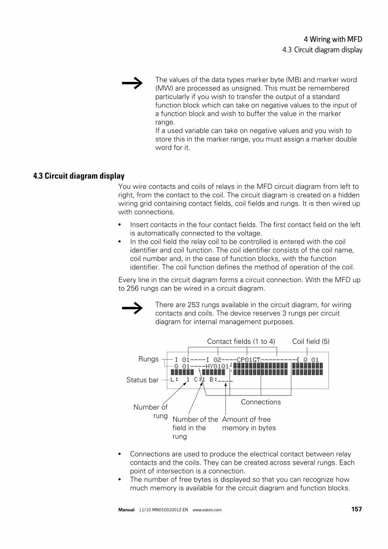
4 Wiring with MFD
4.3 Circuit diagram display
Manual 11/10 MN05002001Z-EN www.eaton.com 157
4.3 Circuit diagram displayYou wire contacts and coils of relays in the MFD circuit diagram from left to right, from the contact to the coil. The circuit diagram is created on a hidden wiring grid containing contact fields, coil fields and rungs. It is then wired up with connections.
• Insert contacts in the four contact fields. The first contact field on the left is automatically connected to the voltage.
• In the coil field the relay coil to be controlled is entered with the coil identifier and coil function. The coil identifier consists of the coil name, coil number and, in the case of function blocks, with the function identifier. The coil function defines the method of operation of the coil.
Every line in the circuit diagram forms a circuit connection. With the MFD up to 256 rungs can be wired in a circuit diagram.
• Connections are used to produce the electrical contact between relay contacts and the coils. They can be created across several rungs. Each point of intersection is a connection.
• The number of free bytes is displayed so that you can recognize how much memory is available for the circuit diagram and function blocks.
→ The values of the data types marker byte (MB) and marker word (MW) are processed as unsigned. This must be remembered particularly if you wish to transfer the output of a standard function block which can take on negative values to the input of a function block and wish to buffer the value in the marker range. If a used variable can take on negative values and you wish to store this in the marker range, you must assign a marker double word for it.
→ There are 253 rungs available in the circuit diagram, for wiring contacts and coils. The device reserves 3 rungs per circuit diagram for internal management purposes.
I 01----I 02----CP01GT---------Ä Q 01 Q 01----HY01Q1kêêêêêêêêêêêêêê êêêêêêêê êêêêêê 'êêêêêê 'êêêêêêêêêêêêêê êêêêêêêê L: 1 C:1 B:____
Contact fields (1 to 4) Coil field (5)
Connections
Rungs
Status bar
Number of rung
Number of the field in the rung
Amount of free memory in bytes

4 Wiring with MFD
4.4 Program transfer from and to the memory card
158 Manual 11/10 MN05002001Z-EN www.eaton.com
4.3.0.1 MFD circuit diagram displayFor greater legibility the circuit diagram of the MFD device shows two contacts or one contact plus coil in a row on each rung. A total of 16 characters per circuit connection and three circuit connections plus the status line can be displayed simultaneously.
The cursor buttons ú í can be used to change the contact fields. The number of the circuit connection and the contact are displayed in the lower status line.
4.4 Program transfer from and to the memory card Programs are transferred via the serial multi-function interface. There are two possibilities:
• From or to a MFD memory card, → Page 161.• Via the programming cable from or to the COM serial PC interface and
thus from or to the programming software easySoft-Pro, or in the Online Help.
How to remove the cover of the serial multi-function interface, connect a programming cable and fit a memory card is described in → Section "2.8 Connecting the serial multi-function interface“ on page 88.
4.4.1 Information on the memory cardA program with all the necessary parameters can be loaded from the memory card into the MFD device or written from the device to the card.
• Each memory card can hold one MFD program. • Information stored on the memory card is “non-volatile” and thus you
can use the card to archive, transfer and copy your circuit diagram.
On the memory card you can save:
• The program,• All the visualization data of the screens,• All parameter settings of the circuit diagram,
• P pushbuttons.• Input delay (debounce).• Password.• Retention on/off and area.• easyNet configuration.• Setting start in the Terminal mode.• COM-LINK settings.• Daylight Saving Time settings.
I 01----I 02--uQ 01----HY01Q1k
L: 1 C:1 B:7840
→ The circuit diagram display performs two functions:• It is used to edit the circuit diagram in STOP mode.• It is used in RUN mode to check the circuit diagram using
the power flow display.

4 Wiring with MFD
4.4 Program transfer from and to the memory card
Manual 11/10 MN05002001Z-EN www.eaton.com 159
4.4.2 Transfer from/to a device without display or keypadOn devices without display and keypad you can transfer the program as follows:
• with easySoft-Pro from the PC. • automatically from the fitted memory card every time the supply voltage
is switched on (see also → Section "8.2.3.2 CARD MODE“, page 453).
The MFD devices without a display are activated automatically when CARD MODE is active.
4.4.3 Compatibility of program and MFD deviceThe easy800 and MFD device families allow programs from an older version to be read in newer device versions without any restrictions in function.
4.4.3.1 CompatibilityDefinition
Downward compatibility is provided when a newer version of a software can open and process a program created with an older version.
Upward compatibility is provided when an older version of a software can open and process a program created with a newer software version.
Downward compatibility with MFD devices
A memory card with a program and a visualization application can always be read by an MFD device that has a newer operating system (with a higher version number) than the device from which the memory card was written. The program read back and/or the visualization application is executable.
→ However, observe the restrictions for different device versions described in the following section!
→ The MFD-CP10... does not support easy800 programs.

4 Wiring with MFD
4.4 Program transfer from and to the memory card
160 Manual 11/10 MN05002001Z-EN www.eaton.com
Upward compatibility on MFD devices
If a program is written to the memory card by an MFD device with a newer operating system, this program can also be read and run by an MFD device with an older operating system. This requires that the program does not contain any functions that are not supported by the older operating system.
A visualization application is not transferred to an MFD device with an older operating system.
If the program contains functions that are not supported by the older operating system, the PROG INVALID! fault message appears with the CARD -> DEVICE transfer.
Table 26: Compatibility matrix for program exchange between devices
Program exchange between devices with memory card or easySoft-Pro
Programs can be loaded and run on devices with the same device version within the easy800 device family or devices with the same device version within the MFD-Titan device family, even if the target device does not have the necessary hardware requirements, see example.
Example: A program with NET operands (e.g. 3RN01) that was created for a network-enabled MFD-Titan is loaded on an MFD-Titan without an easyNet connection. On the MFD without the easyNet connection, all NET operands supply the value zero.
Write card from device …→
↓ Card read with device…
MFD-CP8, V01 MFD-CP8, V05 MFD-CP8, V08 MFD-CP10, [OS-V1.00]
MFD-CP8, V01 OK – – –
MFD-CP8, V05 OK OK – –
MFD-CP8, V08 OK OK OK –
MFD-CP10, [OS-V1.00] OK OK OK OK

4 Wiring with MFD
4.4 Program transfer from and to the memory card
Manual 11/10 MN05002001Z-EN www.eaton.com 161
4.4.4 Loading and saving with a memory cardThe loading of a program from the memory card and the saving on the card is carried out via the CARD menu. The following overview shows how you operate with and without password.
For easy800 and MFD-CP8 devices only use the EASY-M-256K card. With MFD-CP10... use the EASY-M-512K card for storing and reading a program. An MFD-CP10... can read the EASY-M-256K card in order to load an MFD-...-CP8 program.
Figure 107: Choose CARD menu
When a memory card is fitted, and when the programs in the device and on the card are different, the MFD always loads the program from the card.
→ The program is only transferred in STOP operating mode and when the supply voltage is switched on. If the supply voltage fails when the card is accessed, you must repeat the transfer as the data is possibly not fully transferred.
YesPassword protected?
PROGRAM...
STOP å RUNPARAMETER
SET CLOCK... æINFORMATION
ENTRY
PASSWORD
XXXXXX
no
SMain menu
DEVICE-> CARD
CARD -> DEVICE
DELETE CARD
→ Page 162→ Page 162→ Page 164
With password entry and OK
PROGRAM
DELETE PROGRAM
CARD
PASSWORD...
STOP å RUNPARAMETER
SET CLOCK... æINFORMATION

4 Wiring with MFD
4.4 Program transfer from and to the memory card
162 Manual 11/10 MN05002001Z-EN www.eaton.com
4.4.4.1 Saving a program on the memory card (DEVICE -> CARD)
Basic requirements:
• The device in the STOP.• A memory card must be fitted in the device.• You are in the CARD menu and password protection is removed,
→ Figure 107, page 161.
Select DEVICE->CARD. Confirm the confirmation request with OK or abort the save operation
with ESC.
Figure 108: Save program on card
4.4.4.2 Loading the program from the card (CARD -> DEVICE)If a program on the memory card is invalid, a program in the MFD device is retained.
Basic requirements:
• The device in the STOP.• A memory card with a valid program or a circuit diagram must be fitted in
the device.• You are in the CARD menu and password protection is removed,
→ Figure 107, page 161.
Select DEVICE->CARD. Confirm the confirmation request with OK or abort the load operation
with ESC.
→ In devices without a display and keypad, transferring a program to the memory card is not possible.
DEVICE -> CARD
REPLACE?no
Cancel The program is transferred to the card.
Yes
Yes
OK
ESC
→ All passwords that are present when saving to the card are also reactivated after the card is loaded.

4 Wiring with MFD
4.4 Program transfer from and to the memory card
Manual 11/10 MN05002001Z-EN www.eaton.com 163
If there are transmission problems, MFD will display the INVALID PROG message.
Possible causes:
• The memory card is empty. • A checksum error was detected when comparing the stored checksum
and the checksum calculated for the transfer.• The circuit diagram on the card uses a function block that the MFD
device does not recognize, for example the PO, Pulse Output function block.
Figure 109: Loading a program from the card
1) The storing device saves its type and version on the card. A program to be loaded from the card must be suitable for the destination device otherwise this will refuse the transfer.
2) If there is a transfer problem or a check sum error, the MFD device will output the message PROG INVALID.
→ An MFD-CP8... can load a program from the EASY-M-256K card. An MFD-CP10... can load a program from the EASY-M-256K and EASY-M-512K cards.
PROG. INVALID
Empty card?
CARD -> DEVICE
Cancel
Yes
The program is transferred to the device2)
CARD menu is left without any operation
no
PROG. INVALID
ESC
OK
Display
OK
Yes
REPLACE?
The program is suitable for the
device?1)
no

4 Wiring with MFD
4.5 Deleting a program on the card
164 Manual 11/10 MN05002001Z-EN www.eaton.com
4.5 Deleting a program on the card
Requirement: You must be in the CARD menu.
Select the DELETE CARD menu. Confirm the safety prompt DELETE ? with OK if you wish to delete the
card content.
Press ESC to cancel.
After transferring or deleting a program, remove the memory card and close the cover.
4.6 Loading and saving with Soft-Pro easySoft-Pro is a PC program with which you can do the following to an MFD program and a visualization application:
• create it.• test it in a simulation tool. • document and manage it.• write or read it to or from a connected and functional MFD device. • test it in RUN mode (Online) in the actual wiring.
Further information with detailed operator manual on the easySoft-Pro programming software is provided in the online help.
Launch easySoft-Pro and then open the Help system by clicking ? or by pressing function key F1
If there is a transfer error, the MFD device shows the PROG. INVALID message.
Check whether you are using functions that the MFD device does not recognize.
DELETE ?
→ Only use the programming cable provided in the original accessories for transferring data between the PC and the MFD device (→ Section "2.8.1 Connection to a PC“ on page 89).
CAUTION
When connecting the programming cable, the easySoft-Pro programming software must be offline. On no account should the programming cable be replugged from one MFD device to another when a connection has been established (online status).
→ A MFD device cannot exchange data with the PC if it has been switched to the circuit diagram display.
PROG. INVALID
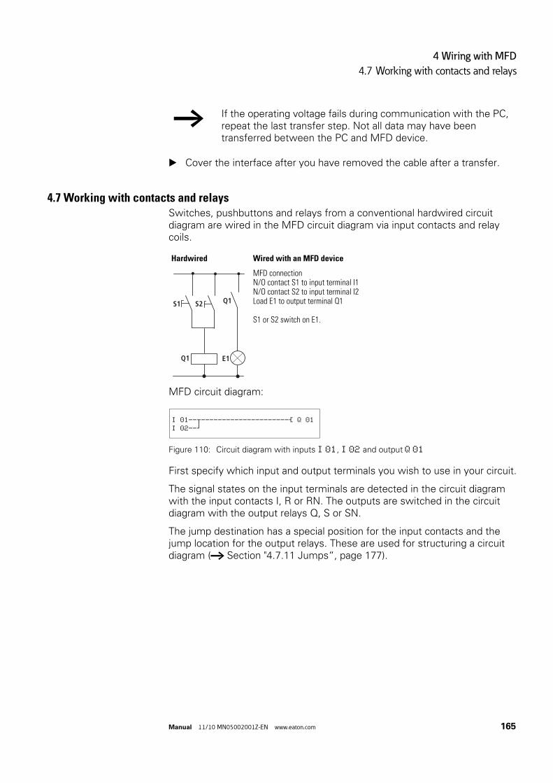
4 Wiring with MFD
4.7 Working with contacts and relays
Manual 11/10 MN05002001Z-EN www.eaton.com 165
Cover the interface after you have removed the cable after a transfer.
4.7 Working with contacts and relaysSwitches, pushbuttons and relays from a conventional hardwired circuit diagram are wired in the MFD circuit diagram via input contacts and relay coils.
MFD circuit diagram:
Figure 110: Circuit diagram with inputs I 01, I 02 and output Q 01
First specify which input and output terminals you wish to use in your circuit.
The signal states on the input terminals are detected in the circuit diagram with the input contacts I, R or RN. The outputs are switched in the circuit diagram with the output relays Q, S or SN.
The jump destination has a special position for the input contacts and the jump location for the output relays. These are used for structuring a circuit diagram (→ Section "4.7.11 Jumps“, page 177).
→ If the operating voltage fails during communication with the PC, repeat the last transfer step. Not all data may have been transferred between the PC and MFD device.
Hardwired Wired with an MFD device
MFD connectionN/O contact S1 to input terminal I1N/O contact S2 to input terminal I2Load E1 to output terminal Q1
S1 or S2 switch on E1.
E1
S1
Q1
Q1S2
I 01--u---------------------Ä Q 01I 02--k

4 Wiring with MFD
4.7 Working with contacts and relays
166 Manual 11/10 MN05002001Z-EN www.eaton.com
4.7.1 Entering and changing contacts and coilsThe following describes how you wire the different contacts and coils of different relay types or function blocks (inputs) in the circuit diagram.
4.7.1.1 ContactsYou choose an input contact in the MFD device by means of the contact name and the contact number.
Example: Input contact basic device
or
Example: Input contact via NET (here from NET station 3)
The contact of a function block consists of the abbreviated function block name, the number and the contact function.
Example: Contact of "comparator" function block
How a safety or standard function block is added to the circuit diagram and parameterized is described in → Section "4.9 Working with function blocks“ on page 188.
If the contact of an Net station is used in the circuit diagram, the NET ID (address) of the station is placed in front of the contact name, → section “4.7.12.1 Setting the NET ID of a NET operand”, page 179.
Example: Contact of a NET station
I 02
Contact name
Contact number
3I02
Station address
Contact name
Contact number
CP01GT
Contact name
Contact number
(= function block number)
Contact function
2RN02
Station address
Contact name
Contact number

4 Wiring with MFD
4.7 Working with contacts and relays
Manual 11/10 MN05002001Z-EN www.eaton.com 167
4.7.1.2 CoilsWith a relay coil or a function block, you choose the coil function, coil name, coil number as well as the function block coil. With coils of an easyNet station, choose the address (NET ID) in front of the coil name.
Example: Relay coil "Output Q"
Example: Relay coil for timing relay function block with control coil
Example: Relay coil of a NET station
Values for contacts and coil fields are changed in Entry mode. The value to be changed flashes.
Use ú í ÍÚ to move the cursor to a contact or coil field. Press OK to switch to Entry mode. Use ú í to select the position you wish to change and press OK to move
to the next position (a selected position is shown in light grey in the following figure).
Use ÍÚ to modify the value of the position.
→ The coil number in the figures on the left must be the same as the function block number!
S Q 04
Coil Function
Coil name
Coil number
Ä T 04ENCoil Function
Coil name
(= function block name)
Coil number
Function block coil
S2SN04
Coil Function
Station address
Coil number
Coil name
→ A complete list of all contacts and coils, → section “11.4 List of function blocks”, page 516.
I 01
→ The MFD device proposes contact I 01 or the coil Ä Q 01 for entry in an empty field.

4 Wiring with MFD
4.7 Working with contacts and relays
168 Manual 11/10 MN05002001Z-EN www.eaton.com
The MFD device closes entry mode as soon as you leave a contact or coil field with ú í or OK.
4.7.1.3 Deleting contacts and coils Use ú í ÍÚ to move the cursor to a contact or coil field. Press DEL.
The contact or the coil will be deleted, together with any connections.
4.7.1.4 Changing N/O contacts to N/C contactsYou can define each contact in the circuit diagram as a N/O or N/C.
Switch to Entry mode and move the cursor over the contact name. Press ALT. The N/O contact will change to a N/C contact. Press OK twice to confirm the change.
Figure 111: Change contact I 03 from N/O to N/C
In the contact field to change I 01 to I 02
In the coil field change Ä Q 01 to S Q 08
I 01 I 02 Ä Q 01 S 0Q 01 S 0Q 01 S0Q 08
M 1 x í + 1 x Í
03 OK + 3 x í + OK
R 2 x ú + 2 x Ú + OK
T 1 x í 02 Úq 04 S q 03
HW 05 ä S .
… 06 È SN .
. è … .
. Å 08
.
OK 99 OK
I 02--u--- I 03--k
I 02--u---- I 03--k
I 02--u---- I 03--kê
ALT OK2 x

4 Wiring with MFD
4.7 Working with contacts and relays
Manual 11/10 MN05002001Z-EN www.eaton.com 169
4.7.2 Creating or changing connections Contacts and relay coils are connected with the wiring arrow in Connect mode. The MFD device displays the cursor in this mode as a wiring arrow.
Use ú í ÍÚ to move the cursor to the contact or coil field from which you wish to create a connection.
Press ALT to switch to Connect mode. Use ú í to move the arrow between the contact and coil fields and use ÍÚ
to move between the rungs. Press ALT to leave Connect mode.
The MFD device closes the mode automatically as soon as you have moved the arrow to an occupied contact or coil field.
Never wire backwards, → Section "9.1.3.2 Example: Do not wire backwards“, page 469.
Figure 112: Circuit diagram with five contacts, invalid
With more than four contacts in series, use one of the 96 M markers.
Figure 113: Circuit diagram with M marker relay
4.7.2.1 Deleting Connections Move the cursor onto the contact field or coil field to the right of the
connection that you want to delete. Press ALT to switch to Connect mode.
Press DEL.
The MFD device deletes a connection branch. Closed adjacent connections will be retained.
Close the delete operation with ALT or by moving the cursor to a contact or coil field.
l
→ Do not position the cursor on the first contact field. Here the ALT button has a different function (add rung).
→ In a rung, the MFD device connects contacts and the connection to the relay coil automatically if no empty fields are between them.
I 01----Q 04----I 03--o z---------------k h-I 02----I 04-----------S Q 02
I 01----Q 04----I 03-----------S M 01 I 02----I 04----M 01-----------S Q 02

4 Wiring with MFD
4.7 Working with contacts and relays
170 Manual 11/10 MN05002001Z-EN www.eaton.com
4.7.3 Adding or deleting rungsThe circuit diagram display shows three of the 256 rungs at the same time. Rungs outside of the display, including empty rungs, are scrolled by MFD automatically in the circuit diagram display if you move the cursor beyond the top or bottom of the display.
A new rung is added below the last connection or inserted above the cursor position:
Position the cursor on the first contact field of a rung. Press ALT.
The existing rung with all its additional connections is “shifted” downwards. The cursor is then positioned directly in the new rung.
Figure 114: Inserting a new rung
4.7.4 Saving circuit diagrams Press ESC to save a circuit diagram.
The menu on the left appears in the status line.
Pressing OK will save the entire program, circuit diagram and function blocks.
After saving, you will be returned to the previous menu from which you have opened the circuit diagram.
4.7.5 Aborting circuit diagram entry Press ESC to leave the circuit diagram entry without saving. Use the cursor buttons ÍÚ to select the CANCEL menu. Press OK.
The circuit diagram is closed without saving.
I 02--u------ I 03--k
I 02--u------- n I 03--k
I 01----I 02--uQ 01----HY01Q1k ÆSAVE æ
I 01----I 02--uQ 01----HY01Q1k ÆCANCEL æ

4 Wiring with MFD
4.7 Working with contacts and relays
Manual 11/10 MN05002001Z-EN www.eaton.com 171
4.7.6 Searching for contacts and coilsBoolean operands or function blocks that are wired as contacts or coils can be found in the following way:
Press ESC. Use the cursor buttons ÍÚ to enter the SEARCH menu. Press OK.
Use the cursor buttons Ú and ú í to select a contact or coil as well as the required number.
For a function block you select the function block name and the number.
Confirm the search with the OK pushbutton.
The search starts from where the search was called and is continued to the end of the circuit diagram. If the required contact or the coil are not found, the search starts at the beginning of the circuit diagram. If the search is successful, you are taken automatically to the required contact or coil field in the circuit diagram.
4.7.7 Got to a rungThe GO TO function can be used to go to a different rung.
Press ESC and use cursor buttons ÍÚ to select the GO TO menu. Press OK. Select the required rung (L?) with the ÍÚ cursor buttons.
Always the first contact of the rung is displayed.
Press OK.
The cursor stops at the first contact L 1 of the required rung.
4.7.8 Delete RungThe MFD device only removes empty rungs (without contacts or coils).
Delete all contacts and coils from the rung. Position the cursor on the first contact field of the empty rung. Press DEL.
The subsequent rung(s) will be “pulled up” and any existing links between rungs will be retained.
I 01----I 02--uQ 01----HY01Q1k ÆSEARCH æ
I 01----I 02--uQ 01----HY01Q1k
SEARCH I 01
I 01----I 02--uQ 01----HY01Q1k
L: 1 C:1 B:7140
I 01----I 02--uQ 01----HY01Q1k
L: 1 C:1 B:7140
I 01----I 02--uQ 01----HY01Q1k
L: 1 C:1 B:7140
→ You can use the "GO TO" function to jump to any rung, up to the last wired rung.

4 Wiring with MFD
4.7 Working with contacts and relays
172 Manual 11/10 MN05002001Z-EN www.eaton.com
4.7.9 Switching with the Cursor ButtonsAn MFD-CP8... enables you to use the four cursor buttons as hard-wired inputs in the circuit diagram if these are assigned P button functions in the button editor → section “6.6.12 P button function”, page 427.
The other operator buttons on the MFD-CP10... can be used as additional inputs.
The cursor buttons are wired in the circuit diagram as contacts P 01 to P 04.
Requirement for switching with the cursor buttons: The P buttons must be activated in the System menu → section “1.6.10 System menu”, page 34.
The P buttons can also be used for testing circuits or manual mode. These button functions are also useful for servicing and commissioning purposes.
Example 1This standard circuit diagram example enables a lamp at output Q1 to either be switched on or off via the inputs I1 and I2 or via the cursor buttons ÍÚ.
Figure 115: Switch Q1 via I1, I2, Í, or Ú
Example 2This circuit diagram example causes output Q1 to be actuated by input I1. I5 switches to cursor operation and disconnects the rung I 01 via M 01.
Figure 116: I5 switches to cursor buttons.
The Status menu display shows whether the P buttons are used in the circuit diagram.
Display in Status display:
• P: Button function wired and active,• P2: Pushbutton function wired, active and P2 pushbutton Í executed,• P-: Button function wired, not active,• Empty field: P pushbuttons not used.
P02
P01
P04
P03
→ The MFD device only evaluates P button entries if the status display is shown.
I 01--u------------------------S Q 01 P 02--k I 02--u------------------------R Q 01 P 04--k
I 05--------------------------S M 01
I 01----M 01--u---------------S Q 01 P 01----M 01--k
I123456789…
P2
MO 14:55
Q.2…6.8 RUN

4 Wiring with MFD
4.7 Working with contacts and relays
Manual 11/10 MN05002001Z-EN www.eaton.com 173
4.7.9.1 Checking the circuit diagramThe MFD device features an integrated power flow display with which you can follow the switching states of contacts, relay and function block coils during operation.
Create the small parallel circuit below and save it.
Figure 117: Parallel connection
Switch the MFD to RUN via the main menu. Return to the circuit diagram display.
You are now unable to edit the circuit diagram.
The circuit diagram display performs two functions depending on the mode:
• STOP: Create the circuit diagram.• RUN: Power flow display.
Switch on I3.
Figure 118: Power flow display
In the power flow display, energized connections are thicker than non-energized connections.
You can follow energized connections across all rungs by scrolling the display up and down.
The power flow display indicates at the bottom right the controller is in RUN mode. (→ section “ Power flow display with Zoom function”, page 105)..
→ If you change to the circuit diagram display but cannot change a circuit diagram, first check whether the MFD device is in STOP mode.
→ The power flow display does not show signal changes in the millisecond range due to the inherent technical delay of LCD displays.
I 02--u------------------------S Q 01 I 03--k
I 02--u------------------------S Q 04 I 03--k
L:001 C:1 RUN

4 Wiring with MFD
4.7 Working with contacts and relays
174 Manual 11/10 MN05002001Z-EN www.eaton.com
4.7.10 Coil FunctionsYou can set the coil function to determine the switching behavior of relay coils. The following coil functions are available for all coils:
Table 27: Coil Function
4.7.10.1 Coil with contactor function Ä The output signal follows the input signal directly, the relay operates as a contactor.
Figure 119: Contactor function signal diagram
MFD display Coil Function Example → Page
Ä Contactor Function ÄQ01,ÄD02,ÄS04,Ä:01,ÄM07,.. 174
ä Impulse Relay Function äQ03,äM04,äD08,äS07,ä:01,.. 175
S Set SQ08,SM02,SD03,SS04.. 175
R Reset RQ04,RM05,RD07,RS03.. 175
Å Contactor function with negated result
ÅQ04, ÅM96.. 176
È Cycle pulse on rising edge ÈM01.. 176
è Cycle pulse on falling edge èM42.. 176
→ The function block coil functions that can be used are described with the function blocks.
→ With non-retentive coil functions such as Ä (contactor), Å (negated contactor), È, è (rising and falling edge evaluation): Each coil must only be used once. The last coil in the circuit diagram determines the state of the relay. Exception: When working with jumps, the same coil can be used twice.Retentive coil functions such as S, R, ä can be used several times.
on
on

4 Wiring with MFD
4.7 Working with contacts and relays
Manual 11/10 MN05002001Z-EN www.eaton.com 175
4.7.10.2 Impulse relay äThe relay coil switches whenever the input signal changes from 0 to 1. The relay behaves like a bistable flip-flop.:
Figure 120: Impulse relay signal diagram
A coil is automatically switched off in the event of a power failure and in STOP mode. Exception: Retentive coils retain signal 1 (→ Section "8.2.7 Storing data retentively (Retention menu item...)“, page 458).
4.7.10.3 “Set” S and “Reset” R coil functionThe Set S and Reset R coil functions are normally used in pairs.
The relay picks up when the coil is set (A) and remains in this state until it is reset (B) by the coil function.
The supply voltage is switched off (C), the coil is not retentive.
Figure 121: Set and Reset signal diagram
If both coils are actuated simultaneously, the coil with the higher rung number has priority, in this case the reset coil, as shown in the signal diagram at (B).
Figure 122: Simultaneous triggering of Q 01
The above example shows the Reset coil with priority when the Set and Reset coil are triggered at the same time.
on
on
on
on
S
R
on
A B C
I 05---------------------------S Q 01
I 10---------------------------R Q 01

4 Wiring with MFD
4.7 Working with contacts and relays
176 Manual 11/10 MN05002001Z-EN www.eaton.com
4.7.10.4 Coil negation (inverse contactor function) ÅThe output signal follows the inverted input signal, the relay works like a contactor with negated contacts. If the coil is set to 1, the coil will switch its make contacts to 0.
Figure 123: Inverse contactor function signal diagram
4.7.10.5 Rising edge evaluation (cycle pulse) ÈThis function is used if the coil is only meant to switch on a rising edge. When the coil status changes from 0 to 1, the coil switches its make contacts to 1 for one cycle.
Figure 124: Signal diagram of cycle pulse with rising edge
4.7.10.6 Falling edge evaluation (cycle pulse) èThis function is used if the coil is only meant to switch on a falling edge. When the coil status drops out from 1 to 0, the coil switches its make contacts to 1 for one cycle.
Figure 125: Signal diagram of cycle pulse with negative edge
on
on
on
on
→ A set coil is automatically switched off in the event of a power failure and in STOP mode. Exception: Retentive coils retain signal 1 (→ Section "8.2.7 Storing data retentively (Retention menu item...)“, page 458).
on
on

4 Wiring with MFD
4.7 Working with contacts and relays
Manual 11/10 MN05002001Z-EN www.eaton.com 177
4.7.11 JumpsJumps :.. can be used for structuring a circuit diagram.
They replace the function of a selector switch. Jumps can be used, for example, to implement the selection of manual/automatic mode or various machine programs.
Jumps :.. consist of a jump location and a jump destination (label) and are only used in the circuit diagram.
Details on the use of jumps in the function block diagram are provided → Section "5.18 LB, jump label“in on page 294 and → Section "5.17 JC, conditional jump“in on page 291.
The MFD device allows the use of up to 32 jumps.
4.7.11.1 Circuit diagram symbols for jumps
4.7.11.2 Function of jumpsIf the jump coil is triggered, the rungs after the jump coil are no longer processed. The states of the coils before the jump will be retained, unless they are overwritten in rungs that were not missed by the jump. Jumps are always made forwards, i.e. the jump ends on the first contact with the same number as that of the coil.
• Coil = jump on 1 state• Contact only at the first leftmost contact = Jump label
The jump contact location is always 1.
Contact
N/O contact1) :
Numbers 01 up to 32
Coils Ä
Numbers 01 up to 32
Coil Function Ä, Å, ä, È, è
1) Can only be used as first contact on the left
→ Backward jumps cannot be executed due to the way in which MFD works. If the jump label does not come after the jump coil, the jump will be made to the end of the circuit diagram. The last rung is also skipped.Multiple usage of the same jump coil and the same contact is possible as long as this is done in pairs, this means:• Coil Ä:1/jumped area/contact :1,• Coil Ä:1/jumped area/contact :1,etc.

4 Wiring with MFD
4.7 Working with contacts and relays
178 Manual 11/10 MN05002001Z-EN www.eaton.com
4.7.11.3 Power flow display of skipped areaJumped sections are indicated by the coils in the power flow display. All coils after the jump coil are shown with the symbol of the jump coil.
4.7.11.4 Example for jumps A selector switch is used to select two different sequences.
• Sequence 1: Switch on motor 1 immediately.• Sequence 2: Activate barrier 2, wait time, then switch on motor 1.
Contacts and relays used:
• I1 sequence 1• I2 sequence 2• I3 guard 2 moved out• I12 motor protective circuit breaker switched on• Q1 motor 1• Q2 guard 2• T 01 wait time 30.00 s, on-delayed• D 01 Text “Motor protective circuit breaker tripped”
CAUTION
If rungs are skipped, the states of the coils are retained. The time of started timing relays continues to run.
Circuit diagram: Power flow display: I 01 selected:
Range from jump label 1 processed.
Jump to label 8.Range to jump label 8 skipped.
Jump label 8, circuit diagram processed from this point on.
I 01------Ä :01I 02------Ä :02: 01
--------u-Ä Q01 h-R Q02----------Ä :08: 02------Ä Q02Q 02-I 03-T T02
T 02------Ä Q01: 08
I 12 ------Ä D01
I 01======Ä :01I 02--------:01
: 01
=========uÄ Q01 hR Q02==========Ä :08: 02--------:08
Q 02--I 03--:08
T 02--------:08
: 08
I 12 -------Ä D01

4 Wiring with MFD
4.7 Working with contacts and relays
Manual 11/10 MN05002001Z-EN www.eaton.com 179
4.7.12 Wiring NET operands in the circuit diagramThe NET operands that can be used depend on the operation of the devices on the NET and the following types of application:
4.7.12.1 Setting the NET ID of a NET operandRequirement: You must have selected an I.., R.., Q.., R.., RN.. S.. or SN.. operand in the circuit diagram and Entry mode must have been selected.
This mode is displayed by a flashing operand.
Use the cursor button ú to move the cursor to the position to the left of the operand. A flashing zero appears as the initial value.
Enter the cursor buttons Í or Ú to define the required NET ID; in this case NET ID 7.
Confirm the entry with the OK button.
The local I.., R.., Q.. or S.. operand has been changed to a NET operand nI.., nR.., nQ.. and nS...
Table 28: Location and addressing of the operands via easyNet
Operating devices on the NET Usable NET operands of data type…
Bit 32 Bit (DWord)
REMOTE IO mode; only NET station 1 processes a circuit diagram.
nI.., nR.., nQ.., nS... –
All NET stations each process a circuit diagram. nI.., nR.., nQ.., nS.., nRN.., nSN...
nPT.. and nGT...
Mixed operation of NET stations with and without a circuit diagram.
nI.., nR.., nQ.., nS.., nRN.., nSN...
nPT.. and nGT...
I 01
L: 1 C:1 B:7732
7I 01
L: 1 C:1 B:7732
Station Basic device via NET Local expansion via NET Bit data via NET Word data via NET
Input Output Input Output Input Output Receive
nI nQ nR nS nRN nSN Send
1 2 I 1…2 I 16…8 I 1…8 I 16
2 Q 1…2 Q 8…8 Q 1…8 Q 8
2 R 1…2 R 16…8 R 1…8 R 16
2 S 1…2 S 8…8 S 1…8 S 8
2 RN 1…2 RN 32 …8 RN 1…8 RN 32
2 SN 1…2 SN 32 …8 SN 1…8 SN 32
GT 1…
PT 1…
2 1 I 1…1 I 163 I 1…3 I 16…8 I 1…8 I 16
1 Q 1…1 Q 83 Q 1…3 Q 8…8 Q 1…8 Q 8
1 R 1…1 R 163 R 1…3 R 16…8 R 1…8 R 16
1 S 1…1 S 83 S 1…3 S 8…8 S 1…8 S 8
1 RN 1…1 RN 32 3 RN 1…3 RN 32…8 RN 1…8 RN 32
1 SN 1…1 SN 32 3 SN 1…3 SN 32…8 SN 1…8 SN 32
GT 1…
PT 1…
3 1 I 1…1 I 162 I 1…2 I 164 I 1…4 I 16…8 I 1…8 I 16
1 Q 1…1 Q 82 Q 1…2 Q 84 Q 1…4 Q 8…8 Q 1…8 Q 8
1 R 1…1 R 162 R 1…2 R 164 R 1…4 R 16…8 R 1…8 R 16
1 S 1…1 S 82 S 1…2 S 84 S 1…4 S 8…8 S 1…8 S 8
1 RN 1…1 RN 32 2 RN 1…2 RN 324 RN 1…4 RN 32…8 RN 1…8 RN 32
1 SN 1…1 SN 32 2 SN 1…2 SN 324 SN 1…4 SN 32…8 SN 1…8 SN 32
GT 1…
PT 1…

4 Wiring with MFD
4.7 Working with contacts and relays
180 Manual 11/10 MN05002001Z-EN www.eaton.com
4.7.13 Read and write of NET operandsThe NET operands nI.., nR.., nQ.. and nS.. can be read and/or written.
4.7.13.1 Reading of nI.., nR.., nQ.. and nS..n = NET ID of the station with NET operands that are read or written. Each NET station with a standard circuit diagram can read the signal states at the input and output terminals of each other NET station via these operands wired as contacts. This is possible regardless of whether a circuit diagram is being processed or not on the NET station to be read. Use these nI.., nR.., nQ.. and nS.. NET operands to read the signal states of NET stations (NET-ID 2 - 8).
4.7.13.2 Reading inputs/outputs of an easySafety device via the NETInputs/outputs IS../QS of an easySafety device can be read in the circuit diagram of an MFD device via the NET operands nI.. and nQ...
Refer to the operator manual for the easySafety ES4P.... control relay for information how to complete the assignment.
4 1 I 1…1 I 162 I 1…2 I 163 I 1…3 I 165 I 1…5 I 16…8 I 1…8 I 16
1 Q 1…1 Q 82 Q 1…2 Q 83 Q 1…3 Q 85 Q 1…5 Q 8…8 Q 1…8 Q 8
1 R 1…1 R 162 R 1…2 R 163 R 1…3 R 165 R 1…5 R 16…8 R 1…8 R 16
1 S 1…1 S 82 S 1…2 S 83 S 1…3 S 85 S 1…5 S 8…8 S 1…8 S 8
1 RN 1…1 RN 32 2 RN 1…2 RN 323 RN 1…3 RN 325 RN 1…5 RN 32…8 RN 1…8 RN 32
1 SN 1…1 SN 32 2 SN 1…2 SN 323 SN 1…3 SN 325 SN 1…5 SN 32…8 SN 1…8 SN 32
GT 1…
PT 1…
5 1 I 1…1 I 16…4 I 1…4 I 166 I 1…6 I 167 I 1…7 I 168 I 1…8 I 16
1 Q 1… Q 8…4 Q 1…4 Q 86 Q 1…6 Q 87 Q 1…7 Q 88 Q 1…8 Q 8
1 R 1…1 R 16…4 R 1…4 R 166 R 1…6 R 167 R 1…7 R 168 R 1…8 R 16
1 S 1…1 S 8…4 S 1…4 S 86 S 1…6 S 87 S 1…7 S 88 S 1…8 S 8
1 RN 1…1 RN 32 …4 RN 1…4 RN 326 RN 1…6 RN 327 RN 1…7 RN 328 RN 1…8 RN 32
1 SN 1…1 SN 32 …4 SN 1…4 SN 326 SN 1…6 SN 327 SN 1…7 SN 328 SN 1…8 SN 32
GT 1…
PT 1…
6 1 I 1…1 I 16…5 I 1…5 I 167 I 1…7 I 168 I 1…8 I 16
1 Q 1…1 Q 8…5 Q 1…5 Q 87 Q 1…7 Q 88 Q 1…8 Q 8
1 R 1…1 R 16…5 R 1…5 R 167 R 1…7 R 168 R 1…8 R 16
1 S 1…1 S 8…5 S 1…5 S 87 S 1…7 S 88 S 1…8 S 8
1 RN 1…1 RN 32 …5 RN 1…5 RN 327 RN 1…7 RN 328 RN 1…8 RN 32
1 SN 1…1 SN 32 …5 SN 1…5 SN 327 SN 1…7 SN 328 SN 1…8 SN 32
GT 1…
PT 1…
7 1 I 1…1 I 16…6 I 1…6 I 168 I 1…8 I 16
1 Q 1…1 Q 8…6 Q 1…6 Q 88 Q 1…8 Q 8
1 R 1…1 R 16…6 R 1…6 R 168 R 1…8 R 16
1 S 1…1 S 8…6 S 1…6 S 88 S 1…8 S 8
1 RN 1…1 RN 32 …6 RN 1…6 RN 328 RN 1…8 RN 32
1 SN 1…1 SN 32 …6 SN 1…6 SN 328 SN 1…8 SN 32
GT 1…
PT 1…
8 1 I 1…1 I 16…8 I 1…8 I 16
1 Q 1…1 Q 8…8 Q 1…8 Q 8
1 R 1…1 R 16…8 R 1…8 R 16
1 S 1…1 S 8…8 S 1…8 S 8
1 RN 1…1 RN 32…7 RN 1…7 RN 32
1 SN 1…1 SN 32 …7 SN 1…7 SN 32
GT 1…
PT 1…
Station Basic device via NET Local expansion via NET Bit data via NET Word data via NET
Input Output Input Output Input Output Receive
nI nQ nR nS nRN nSN Send

4 Wiring with MFD
4.7 Working with contacts and relays
Manual 11/10 MN05002001Z-EN www.eaton.com 181
4.7.13.3 Writing of nQ.. and nS..Only NET station 1 has write access via the nQ.. and nS.. operands. It writes via coils nQ.. and nS.. to the output terminals of another NET station which is running in REMOTE IO mode without a circuit diagram.
Example 1:
NET station 1 is required to read data from input I1 of NET station 2 and write data to output Q1 of NET station 2. NET station 2 does not have a circuit diagram.
Figure 126: Circuit diagram in NET station 1
4.7.14 NET operands nRN.. (input) and nSN.. (output)To use these NET operands, the sending and receiving station must each have a circuit diagram.
The NET stations for bit exchange must always use the RN and SN in pairs (→ Figure 127, page 182 and 128).
4.7.14.1 Writing via SNThe NET operand SN (Send NET) is used for sending bit data from one NET station to another. To do this you select the SN operand in a coil field.
4.7.14.2 Reading using RNThe RN (Receive NET) NET operand is used to receive the bit data that another NET station has sent. To do this you select the RN operand in a contact field.
4.7.14.3 SN-RN combinationAs the RN and SN must always be used in pairs, the following rule applies:
• on the sending station and receiving station use the same operand number for each SN/RN pair to be formed.
• in the circuit diagram of the sending station you set for the SN operand (coil) the station number (NET ID) of the receiving station.
• in the circuit diagram of the receiving station you set for the RN operand (contact) the station number (NET ID) of the sending station.
2I 01--------------------Ä2Q 01

4 Wiring with MFD
4.7 Working with contacts and relays
182 Manual 11/10 MN05002001Z-EN www.eaton.com
Figure 127: SN-RN combinations of NET station 1
NET-ID 1
NET-ID 2
NET-ID 3
NET-ID 4
NET-ID 5
NET-ID 6
NET-ID 7
NET-ID 8
1SN
2SN
4SN
6SN
7SN
8SN
1RN
2RN
3SN3RN
4RN
6RN
7RN
8RN
1SN
2SN
5SN
6SN
7SN
8SN
1RN
2RN
3SN3RN
5RN
6RN
7RN
8RN
1SN
2SN
4SN
5SN
6SN
7SN
8SN
1RN
2RN
4RN
5RN
6RN
7RN
8RN
1SN
4SN
5SN
6SN
7SN
8SN
1RN
3SN3RN
4RN
5RN
6RN
7RN
8RN
2RN
4RN
5RN
6RN
7RN
8RN
2SN
3RN3SN
4SN
5SN
6SN
7SN
8SN
1SN
2SN
4SN
5SN
7SN
8SN
1RN
2RN
3SN3RN
4RN
5RN
7RN
8RN
1SN
2SN
4SN
5SN
6SN
8SN
1RN
2RN
3SN3RN
4RN
5RN
6RN
8RN
1SN
2SN
4SN
5SN
6SN
7SN
1RN
2RN
3SN3RN
4RN
5RN
6RN
7RN

4 Wiring with MFD
4.7 Working with contacts and relays
Manual 11/10 MN05002001Z-EN www.eaton.com 183
Figure 128: SN-RN combinations of NET station 8
4.7.15 SN-RN exampleNET station 2 sends the status of the P button P01 via SN1 to NET station 1.
On NET station 1 the status of P1 is associated via RN01 as a count pulse for the counter relay C01.
NET-ID 1
NET-ID 2
NET-ID 3
NET-ID 4
NET-ID 5
NET-ID 6
NET-ID 7
NET-ID 8
1SN...
2SN...
4SN...
6SN...
7SN...
8SN...
1RN...
2RN...
3SN...3RN...
4RN...
6RN...
7RN...
8RN...
1SN...
2SN...
5SN...
6SN...
7SN...
8SN...
1RN...
2RN...
3SN...3RN...
5RN...
6RN...
7RN...
8RN...
1SN...
2SN...
4SN...
5SN...
6SN...
7SN...
8SN...
1RN...
2RN...
4RN...
5RN...
6RN...
7RN...
8RN...
1SN...
4SN...
5SN...
6SN...
7SN...
8SN...
1RN...
3SN...3RN...
4RN...
5RN...
6RN...
7RN...
8RN...
2SN...
4SN...
5SN...
6SN...
7SN...
8SN...
2RN...
3SN...3RN...
4RN...
5RN...
6RN...
7RN...
8RN...
1SN...
2SN...
4SN...
5SN...
7SN...
8SN...
1RN...
2RN...
3SN...3RN...
4RN...
5RN...
7RN...
8RN...
1SN...
2SN...
4SN...
5SN...
6SN...
8SN...
1RN...
2RN...
3SN...3RN...
4RN...
5RN...
6RN...
8RN...
1SN...
2SN...
4SN...
5SN...
6SN...
7SN...
1RN...
2RN...
3SN...3RN...
4RN...
5RN...
6RN...
7RN...
P 01--------------------Ä1SN01
2RN01-------------------ÄC01C_

4 Wiring with MFD
4.8 Wiring COM-LINK operands in the circuit diagram
184 Manual 11/10 MN05002001Z-EN www.eaton.com
4.7.16 NET operand GT.. (receive), PT.. (send) and SC.. (set date and time)The function blocks are of data type 32-bit. They only function if the NET is operating correctly (→ section “9.3 Diagnostics”, page 479). More information about the function blocks → section “5 Function blocks”, page 199
4.8 Wiring COM-LINK operands in the circuit diagramRequirements for using COM-LINK operands: The COM-LINK connection between MFD-Titan and the remote station must be physically implemented, configured and activated (→ section “3.8 COM-LINK connection”, page 132).
4.8.1 Operand access in the active MFDIf you access the operands of the remote device via the COM-LINK connection, the station number 1 must be added to the operands of this device in the program of the active MFD, e.g. 1 I3: means input 3 of the remote station.
Example: The active MFD queries input I3 of the remote device. The status is passed to marker M01 of the active MFD.
You can read the following operand types from the remote station (READ):
1I, 1IA*), 1ID, 1Q, 1QA*)
* not with easySafety
If the remote device is connected with an expansion unit, you can also read its inputs/outputs (1R/1S).
If you are using an easySafety device as a remote device, you can also read its safety inputs/outputs IS../QS via 1 I.. and 1Q.. operands. For COM-LINK operands with the fixed station number 1, the same IS../I.. and QS./Q assignment is used as for the NET operands. Refer to the operating manual of the easySafety ES4P.... control relay for information on how to complete the assignment.
You can read markers (READ) or write them (WRITE) from the marker range MD01 - MD20 of the remote device.
→ If the remote station does not have any analog inputs or outputs or no connected expansion unit, these COM-LINK operands are set to 0.
1I 03--------------------Ä M 01

4 Wiring with MFD
4.8 Wiring COM-LINK operands in the circuit diagram
Manual 11/10 MN05002001Z-EN www.eaton.com 185
Figure 129: Access to operand ranges
Figure 130: Access to the marker ranges
Figure 131: Bit marker range for reading and writing defined
Program COM-LINK
MFD (active) (Remote) MFD / easy800 /easySafety
ProgramMemory
I/R/IA
ID
Q/S/QA
MD
Program COM-LINK
MFD (active) (Remote) MFD / easy800
ProgramMemory
MD 20 . . .
. . .
. . .
MD 96
32 31 30 . . . . . 03 02 01 MD 01 64 63 62 . . . . . 35 34 33 MD 02 96 95 94 . . . . . 67 66 65 MD 03
MD 04 . . . . . .
MD 20
MD 01 MD 02 MD 03 MD 04
Program COM-LINK
MFD (active)
Display
READ: 1 MD 01 l 1 MD 02 WRITE: 1 MD 03 l 1 MD 03
(Remote) MFD / easy800
ProgramMarker memoryM01 . . . M96 = Bit Marker
32 31 30 . . . . . 03 02 01 MD 01 64 63 62 . . . . . 35 34 33 MD 02 96 95 94 . . . . . 67 66 65 MD 03
MD 04 . . . . . .
MD 20
READ READ WRITE

4 Wiring with MFD
4.8 Wiring COM-LINK operands in the circuit diagram
186 Manual 11/10 MN05002001Z-EN www.eaton.com
If the active MFD is required to read and/or write some markers in the remote device, a marker range (READ) and/or (WRITE) must be parameterized first of all. Carry out the parameterization on the display/keypad of the active device. Enter the start and the end of the marker range. Only marker double words are accepted as parameters.
Shows an example of assigned parameters → Figure 131, page 185: The READ range starts here at MD01 and ends at MD02. MD03 is defined as the WRITE range.
The remote device normally provides a marker range from MD01 to MD20. The entire range from MD01 to MD96 can be used in the program of the remote device!
Table 29: Operands of the remote station* parameterized marker range (READ)/(WRITE)
Table 29 shows the COM-LINK operands which can be accessed by the active MFD with the COM connection.
Some markers can be addressed as bit, byte, word or double word (→ also → Figure 131, page 185). All marker data types, also double words, are consistent!
Function Operand Range Data type AccessR = ReadW = Write
Remote input (basic device)
easy800 1I 1 - 16 Bit R
easySafety 1I 1 - 14 Bit R
Remote input (expansion unit ) 1R 1 - 16 Bit R
Remote output (basic device)
easy800 1Q 1 - 8 Bit R
easySafety 1Q 1 - 7 Bit R
Remote output (expansion unit ) 1S 1 - 8 Bit R
Analog input 1IA 1 - 4 32 Bit R
Analog output 1QA 1 32 Bit R
Diagnostics ID 1 1 - 16 Bit R
Bit marker 1M 1 - 96 Bit R, W *
Byte markers 1MB 1 - 80 8 bit R, W *
Word markers 1MW 1 - 40 16 bits R, W *
Double word markers 1MD 1 - 20 32 Bit R, W *

4 Wiring with MFD
4.8 Wiring COM-LINK operands in the circuit diagram
Manual 11/10 MN05002001Z-EN www.eaton.com 187
4.8.1.1 Example: reading markersThe active MFD fetches a marker bit from the remote device. The following circuit diagram line is entered in the active MFD.
4.8.1.2 Example: writing markersThe active MFD writes a marker bit to the remote device. The following circuit diagram line is entered in the active MFD.
4.8.2 Access methodThe active MFD controls the data exchange. It reads or write the operands of the remote device cyclically. 120 ms is a guide value for the time required for refreshing a marker double word.
Write/read operands via the COM-LINK connection run asynchronously to program accesses. This applies to the active MFD as well as to the remote device.
4.8.2.1 Operand access in the remote deviceBoth the active MFD-Titan and the remote device can write the markers of the remote device. In this type of dual access, the last entry is always valid.
Monitoring the COM-LINK connection → section “9.6 Monitoring the COM-LINK connection”, page 483.
1M 03--------------------------Ä M 03
M 94--------------------------Ä 1M 08
CAUTION
Due to these factors, the COM-LINK connection should not be used for control purposes but only for visualization tasks!
CAUTION
Avoid double write accesses to the same markers!

4 Wiring with MFD
4.9 Working with function blocks
188 Manual 11/10 MN05002001Z-EN www.eaton.com
4.9 Working with function blocks
This chapter describes further on how to add and parameterize function blocks in the circuit diagram. A detailed description of all available function blocks is provided in the → Section "5 Function blocks“ on page 199. The function blocks are presented there in alphabetical order. This section, however, describes some general notes on working with function blocks.
The function blocks are used to simulate some of the devices used in conventional open-loop and closed-loop control systems. The following applies to function blocks:
→ Current actual values are deleted when you switch off the power supply or switch the MFD device to STOP mode. Exception: Retentive data keeps its state (→ Section "8.2.7 Storing data retentively (Retention menu item...)“, page 458).The most recent actual values are transferred to the operands every cycle. The data function block is an exception.
→ If you want to prevent other people from modifying the parameters of the function blocks, change the access enable symbol from "+" to "–" when creating the circuit diagram and setting parameters. You can then protect the circuit diagram with a password.
→ As every function block in the function block list takes up memory, even if it is no longer being used and has been deleted in the circuit diagram, you should clear it occasionally.Check the function block diagram for any function blocks that are no longer required and delete them, → Section "4.9.4 Deleting function blocks“, page 196.
CAUTION
The following applies to RUN mode: A MFD device processes the function block after a pass through the circuit diagram. This takes the last status of the coils into account.
→ The function blocks are designed so that an output value of a function block can be assigned directly with an input of another function block. The 32-bit data format is used automatically. This also enables the transfer of negative values.

4 Wiring with MFD
4.9 Working with function blocks
Manual 11/10 MN05002001Z-EN www.eaton.com 189
4.9.1 Adding function blocks to the circuit diagram for the first timeAdd a function block to the circuit diagram for the first time in the following way:
Use the Í Ú ú í buttons to move the cursor to a free contact or coil field. Press OK so that the MFD device switches to entry mode.
Then use cursor buttons Í Ú to select the required function block, e.g. timing relay using the T identifier.
When the function block identifier flashes, press OK or the cursor button í to move to the function block number and press OK.
The parameter dialog opens. You can only set Boolean basic parameters here for the standard function blocks. The entire parameterization is carried out in the function block editor. Further information on this is provided in the following chapter.
4.9.2 Setting function block parameters Function blocks are simply called in the circuit diagram and also enter the Boolean basic parameters there. You assign actual value and setpoint parameters for the function block inputs and outputs via the FUNCTION RELAYS menu. You can of course also set the basic parameters in the function block editor and then add the function block in the circuit diagram as a contact or coil.
The edited function blocks are always part of the circuit diagram.
L: 1 C:1 B:7520
T 01Q1
L: 1 C:1 B:7520
T 01Q1
L: 1 C:1 B:7520

4 Wiring with MFD
4.9 Working with function blocks
190 Manual 11/10 MN05002001Z-EN www.eaton.com
Figure 132: Overview of function block parameter assignment
Edit circuit diagram Parameter dialog for basic parameters1)
Main menu:PROGRAM -> PROGRAM -> CIRCUIT DIAGRAM
Saving
Select function block in the list
Parameterize function block in the editor2)
Parameterize other function blocks?
Saving
Ye
ESC
OK
no ESC
Parameterize function block (FB)
ESC
OK
Other function blocks in the list? Yes
no
1) Only Boolean parameters, → Page 1912) All parameters, → Page 192
Main menu:PROGRAM -> PROGRAM -> FUNCTION BLOCKS
OK
END

4 Wiring with MFD
4.9 Working with function blocks
Manual 11/10 MN05002001Z-EN www.eaton.com 191
4.9.2.1 Parameter assignment from the circuit diagramWhen a function block is added for the first time, the parameter dialog is started automatically.
The figure on the left shows an example of a parameter dialog for a "timing relay" function block.
The parameter options available depend on the function block concerned. They cover the basic parameters of the first line up to the +/- character. The +/- symbol is used to switch the Parameter display on or off during RUN mode and thus allow (+) or block (-) the possibility to modify setpoints (constants). The +/- symbol must at least be confirmed with OK.
Use the cursor buttons ú í to select the parameter to be changed, for example the time range “S”.
Use the cursor buttons ÍÚ to change the parameter value to a different time range such as M:S.
Press OK to exit the parameter dialog if you wish to save the parameters or press ESC, if you do not wish to parameterize the function block and add it to the circuit diagram.
After saving or canceling, the cursor returns to the position in the circuit diagram where you last left it.
To complete the parameter setting of the function block, such as the setting of setpoints, call up the function block editor in the following way:
Press ESC in order to save the circuit diagram with the newly added function block.
Answer the subsequent SAVE prompt with OK.
The circuit diagram is saved and the MFD device changes to the next higher menu level.
T 01 X? S +
>I1
>I2
QV>
→ Parameter sets can only be enabled or protected via the FUNCTION RELAYS menu, or via the circuit diagram with the “+” enable and with “–” inhibit parameter set characters.

4 Wiring with MFD
4.9 Working with function blocks
192 Manual 11/10 MN05002001Z-EN www.eaton.com
4.9.2.2 Parameter setting in the function block editor Open the function block editor via the FUNCTION BLOCKS menu. Then first enter the function block list in which the function blocks used are listed.
If no function blocks are shown, the list is empty.
In our example, the list contains the function blocks AR, CP and T. The function blocks are created in the order in which they were edited.
Figure 133: Explanation of the function block list
Use the cursor buttons ÍÚú í to select the required function block from the function block list, in this case timing relay T01.
The timing relay is shown in the function block editor and can be fully assigned parameters here.
Figure 134: Display of the function blocks in the function block editor
ââ
L:001 B:3100
Displays the function blocks used
Function, special function, parameter display
Free memory in bytes
Current cursor line
AR01 ADD +
CP10 +
T 01 ?X -
L:001 B:7420
AR01 ADD +
CP10 +
T 01 ?X -
L:001 B:7420
Parameter display(+ appears/ – does not appear)
Unit/special function
Function block number
Function block name
Function Block Inputs
Function Block Outputs
Variable, operand for outputs
Variable, operand for inputs
Function
T 01 ?X M:S +
>I1 20:30
>I2
QV> MD96

4 Wiring with MFD
4.9 Working with function blocks
Manual 11/10 MN05002001Z-EN www.eaton.com 193
Example: Timing relay function block
Assigning operands at the input of a function block
The following operands can be assigned to the input of a function block:
• Constants, e.g.: 42,• Markers such as MD, MW, MB,• Analog output QA,• Analog inputs IA,• All output variables of the function blocks …QV>
T 01 ?X M:S +
>I1 20:30
>I2
QV> MD96
Function Block: Timing Relay
Switch function: On-delayed with random time
Time range: M:S (Minute:Second)
Set time >I1: 20 min 30 s
Actual time QV>: Copied to MD96
CAUTION
When assigning the parameters of a function block input, ensure that these cannot be triggered with impermissible values during operation. There is a danger of this if you assign a variable that can assume negative values to a standard function block input that can only accept positive values.If, for example, the "T - timing relay" is triggered with a negative time setpoint, it will no longer switch in the expected way.You should therefore take care to exclude such situations, as the MFD device cannot foresee these when the parameters are assigned.If, for example, you have set the output QV of the AR arithmetic function block at input I1 of the T function block, you should connect a CP comparator in between in order to signal the occurrence of a negative value. In most applications, a thorough simulation is enough to prevent any impermissible values at the function block input.

4 Wiring with MFD
4.9 Working with function blocks
194 Manual 11/10 MN05002001Z-EN www.eaton.com
Assigning operands at the output of a function block
Markers such as MD, MW, MB or the analog output QA of the device can be assigned to the variable output QV of a function block.
Deleting operands on the function block inputs/outputs
Position the cursor on the required operand.
Press the DEL pushbutton.
The operand is deleted.
4.9.3 Changing function block parametersA MFD device allows you to change the parameters of function blocks, such as the setpoints of timing or counter relays without calling up the circuit diagram. To change these parameters, the MFD device must be in RUN operating mode.
Parameters of the function blocks that you use in the standard circuit diagram can be changed with the following accesses:
• Access 1 - FUNCTION BLOCKS, STOP modeAll parameters can be set or deleted via PROGRAM -> FUNCTION BLOCKS and the function block editor.
• Access 2- FUNCTION BLOCKS menu, RUN modeYou reach the function block editor via PROGRAM -> FUNCTION BLOCKS. Here you can change setpoints (constants). This access is blocked if the program is password protected.
• Access 3- PARAMETERS menu option, RUN modeChoose PARAMETERS to change the set values (constants). These modification options are also provided if you have saved the program and therefore password protected the function block editor. With the function blocks used you can use the +/- character to set which function blocks allow the changing of their parameters.
Access 1 - FUNCTION RELAYS, STOP mode
This access method is basically no different to the initial parameter assignment of a function block (→ Section "4.9.2.1 Parameter assignment from the circuit diagram“, page 191).
T 01 X? M:S +
>I1 ââ:30 >I2
QV> MD96
T 01 X? M:S +
>I1 ââ >I2
QV> MD96

4 Wiring with MFD
4.9 Working with function blocks
Manual 11/10 MN05002001Z-EN www.eaton.com 195
Access 2 - FUNCTION RELAYS, RUN mode
Requirements for the parameter setting via FUNCTION BLOCKS:
• The function block is used in the standard circuit diagram or function block.
• Access to the parameter set is enabled, indicated by the +/- character at the top right of the display.
Proceed as follows to call the parameter dialog again for changes:
Press OK to enter the main menu. Open the function block list via PROGRAM -> FUNCTION BLOCKS.
First enter the function block list. All function blocks used in the circuit diagram are displayed here.
Use Í or Ú to select the required function block. Press OK. Scroll with the Í or Ú cursor buttons through the constants of the
function block inputs. Change the values for a parameter set:
• OK: Switch to Entry mode.• ú í Change decimal place.• ÍÚ Change value at a decimal place.• OK: Save constant immediately and exit the parameter display by
pressing ESC.ESC: Keep the previous setting and exit the parameter display.
Access 3- PARAMETERS menu, RUN mode
Requirements for parameter assignment via PARAMETERS:
• The MFD device is in RUN mode.• The function block is used in the standard circuit diagram or function
block.• Access to the parameter set is enabled, indicated by the +/- character at
the top right of the display.
Proceed as follows to call the parameter dialog again for changes:
Press OK to enter the main menu. Open the function block list via PARAMETERS.
All function blocks used in the circuit diagram are displayed in the function block list.
Proceed from here described in → section “ Access 2 - FUNCTION RELAYS, RUN mode”, page 195.
T 03 Ü S +CP08 -
C 17 +
L: 1 RUN
→ It is only possible to change input values at function blocks if they are setpoints (constants).
T 03 Ü S +CP08 -
C 17 +
L: 1 RUN

4 Wiring with MFD
4.9 Working with function blocks
196 Manual 11/10 MN05002001Z-EN www.eaton.com
4.9.4 Deleting function blocksRequirement: The MFD device must be in STOP mode.
Move the cursor in the circuit diagram to all the contact fields and the coil field in which the function block to be deleted is used and press DEL each time.
Deleting function blocks from the function block list
In order to prevent accidental deletion, a function block continues to be managed in the function block list, even if it was already removed in the circuit diagram. To delete the function block permanently and therefore to free up more memory, you must remove it from the function block list.
Open the function block list via PROGRAM -> FUNCTION BLOCKS. Select the function block to be deleted in the function block list, in this
case CP10. Press the DEL pushbutton.
The function block is removed from the function block list.
Press ESC in order to save the function block list with the deleted function block.
Answer the subsequent SAVE prompt with OK.
4.9.5 Checking function blocksRequirement for the check: The MFD device must be in RUN mode.
You can check function blocks via the function block editor.Choose PROGRAM... -> FUNCTION BLOCKS to enter the function block list which shows the standard function blocks used.
In the function block list select the required function block.
In this example, select the data block comparator AR01 in Adder mode.
Press OK.
Depending on the display selected the function block is shown with the actual values and the result, or with the set operands and constants.
Press the ALT pushbutton if you wish to switch from operand to actual value display or vice versa during the check of the standard function block.
The operand is displayed.
• >I1= Actual value, here from the output of the counter C 01• >I2= Constant 1095.• QV> = Marker double word MD56.
Press the ALT pushbutton again (see also the following note).
AR01 ADD +
CP10 +
T 18 ?X -
L:002 B:5430
AR01 ADD +
CP10 +
T 18 ?X -
L:001 RUN
AR01 ADD +
>I1 20056
>I2 1095
QV> 21151
AR01 ADD +
>I1 C 01QV>
>I2 1095
QV> MD 56

4 Wiring with MFD
4.9 Working with function blocks
Manual 11/10 MN05002001Z-EN www.eaton.com 197
The display changes again to the display of actual values and the result.
Press ESC to return to the function block list. To leave the check display, press ESC once more and press OK in
answer to the subsequent CANCEL prompt.
AR01 ADD +
>I1 20056
>I2 1095
QV> 21151→ Press ALT to switch likewise to the display of the function
blocks as well as the other contact and coil operands in the circuit diagram. You can use ALT to switch from full but only partial display to a compact display showing all contacts and coils on one circuit diagram line. Pressing ALT once more will switch you back to the original display.

4 Wiring with MFD
4.9 Working with function blocks
198 Manual 11/10 MN05002001Z-EN www.eaton.com

5 Function blocks
5.1 A, analog value comparator/threshold value switch
Manual 11/10 MN05002001Z-EN www.eaton.com 199
5 Function blocks
The following description of the function blocks is in alphabetical order.
5.1 A, analog value comparator/threshold value switchAn analog value comparator or threshold value switch is used, for example, to compare analog values or marker contents and switch when defined threshold values are reached.
MFD allows the use of up to 32 analog value comparators/threshold switches.
5.1.1 Function block inputs/outputs
Read the description of the inputs/outputs in the legend points in column 1 of the following tables.
Analog value comparator A1…A32
Boolean inputs/outputs Parameters
Contact Coil Input value Output value
Q1 1 if the selected actual value/setpoint condition is fulfilled ①
CY Value range exceeded ②
I1 Comparison value 1 ③
F1 Gain factor for I1 (I1 = F1 * value) ④
I2 Comparison value 2 ⑤
F2 Gain factor for I2 (I2 = F2 * value) ⑥
OS Offset for the value at I1, I1 OS = OS + actual value at I1 ⑦
HY Switch hysteresis for value at I2 (value HY is used for both positive and negative hysteresis.) ⑧

5 Function blocks
5.1 A, analog value comparator/threshold value switch
200 Manual 11/10 MN05002001Z-EN www.eaton.com
5.1.2 Wiring of the function blockYou wire the "analog value comparator" function block in the circuit diagram with its contacts.
5.1.3 ContactsA closed contact indicates:
5.1.3.1 Example for function block analog value comparator
Figure 135: Wiring the contacts
5.1.4 Parametric programming of the function block inputs/outputs
5.1.4.1 ParametersWhen using the function block in the circuit diagram for the first time, use OK to automatically enter the general display of function block parameters, as shown in the figure on the left. Enter the function block settings here. The display contains the following elements:
The parameter set consists of:
Parameters Function
① A ..Q1 Reaching of the comparison result, according to the selected operating mode GT, EQ or LT
② A ..CY Value range exceeded
I 01----A 01Q1-----------------Ä Q 01 I 02----A 01CY-----------------S Q 02
A 02 GT +
>I1
>F1
>I2
>F2
>OS
>HY
A 02 Function block analog value comparator number 02
GT Operating mode: Greater than
+ Parameter display: Call enabled
③ >I1 Comparison value 1, is compared with the comparison value 2 at >I2, Value range: -2147483648 - 2147483647
④ >F1 Gain factor for >I1 (>I1 = >F1 x value)Value range: -2147483648 - 2147483647
⑤ >I2 Comparison value 2 I1,Value range: -2147483648 - 2147483647
⑥ >F2 Gain factor for >I2 (>I2 = >F2 x value)Value range: -2147483648 - 2147483647
⑦ >OS Offset (zero point offset) for the value of >I1Value range: -2147483648 - 2147483647
⑧ >HY Positive and negative switching hysteresis for comparison value I2,Value range: -2147483648 - 2147483647

5 Function blocks
5.1 A, analog value comparator/threshold value switch
Manual 11/10 MN05002001Z-EN www.eaton.com 201
Operating Mode
This parameter defines which comparison result is to be used to close function block contact Q1.
The factory setting of this parameter is LT.
Parameter Display
The display of the parameters during operation can be disabled. Additional information → section “4.9.2.1 Parameter assignment from the circuit diagram”, page 191.
This parameter is factory set to +.
Inputs
>I1 and >I2: The signals at function block inputs >I1 and >I2 are compared.
>F1 and >F2: If required adjust the comparison values and increase them by entering gain factors >F1 and >F2.
• >F1 is permanently assigned to >I1.• >F2 is permanently assigned to >I2.
>OS: You can use the offset input >OS to move the zero point of the function block input >I1.
>HY: The >HY function block input is used for the positive and negative switching hysteresis of the input >I2.
All function block inputs can be assigned the following operands:
• Constant.• Markers MD, MW, MB.• Analog inputs IA01 to IA04:
• IA01: Terminal I7.• IA02: Terminal I8.• IA03: Terminal I11.• IA04: Terminal I12.
• Analog output QA01.• Output …QV> of a different function block
Parameters Function, parameterization in the function block
GT >I1 greater than >I2
EQ >I1 equal to >I2
LT >I1 less than >I2
Parameters Function
+ Parameters are displayed
- Parameters are not displayed

5 Function blocks
5.1 A, analog value comparator/threshold value switch
202 Manual 11/10 MN05002001Z-EN www.eaton.com
If they are not associated, the inputs have a default value of:
• >F1 and >F2 = 1• >OS and >HY = 0
Memory requirement
The analog value comparator function block requires 68 bytes of memory plus 4 bytes per constant at the function block inputs.
Cycle time [μs]
The execution time depends on the mode.
5.1.5 Function of the function blockThe function block compares values present at the inputs >I1 and >I2. You control the comparison in the function block by setting other input parameters:
• Multiplication factors >F1 and >F2 for the comparison values 1 and 2,• Offset of comparison value 1 via function block input >OS,• Application of a switch hysteresis to comparison value 2 on >HY.
Contact Q1 indicates the comparison result “greater”, “equal to” or “less” depending on the set operating mode.
Contact CY closes if the value range is exceeded. If an overshoot is indicated with CY = 1, Q1 stays 0. The following equations can be used to calculate the permissible value range.
– 231 ≦ I1 x F1 + OS ≦ (231 – 1) → CY = 0
– 231 ≦ I2 x F2 + HY ≦ (231 – 1) → CY = 0
– 231 ≦ I2 x F2 – HY ≦ (231 – 1) → CY = 0
mode Cycle time [μs]
GT 96
EQ 96
LT 96

5 Function blocks
5.1 A, analog value comparator/threshold value switch
Manual 11/10 MN05002001Z-EN www.eaton.com 203
The following signal diagram illustrates the function:
Figure 136: Signal diagram for analog value comparator
1: Actual value on >I1
2: Setpoint value on >I2
3: Hysteresis on >HY
4: Switch contact (N/O)
5: Offset for value >I1
6: Actual value plus offset
• Range A: Compare >I1 greater than >I2– The actual value >I1 increases.– The contact switches when the actual reaches the setpoint value.– The actual value changes and falls below the value of the setpoint value minus the hysteresis.– The contact goes to the normal position.
• Range B: Compare >I1 less than >I2 – The actual value drops.– The contact switches if the actual value reaches the setpoint value.– The actual value changes and rises above the value of the setpoint value plus hysteresis.– The contact goes to the normal position.
• Range C: Compare >I1 greater than >I2 with offset– This example behaves as described in Range A. The offset value is added to the actual value.
• Comparison >I1 equals >I2The contact switches on:– If I1 is equal to I2, i.e. the actual value is equal to the setpoint value.The contact switches off:
– If the hysteresis limit is exceeded with the actual value rising.– If the hysteresis limit is undershot with the actual value decreasing.
1
32
4
A B C
3 1
6
1
5

5 Function blocks
5.2 AR, Arithmetic
204 Manual 11/10 MN05002001Z-EN www.eaton.com
5.2 AR, Arithmetic
The Arithmetic function block performs all four basic calculations:
• add• subtract• multiply• Divide.
MFD allows the use of up to 32 arithmetic function blocks.
5.2.1 Function block inputs/outputs
Read the description of the inputs/outputs in the legend points in the following tables.
5.2.2 Wiring of the function blockAn arithmetic function block does not require an enable or start signal and is therefore not wired in a coil field of the standard circuit diagram. The function block is provided with the two Boolean outputs mentioned above for controlling the calculation result that you wire as contacts in the circuit diagram.
5.2.2.1 ContactsA closed contact indicates:
5.2.2.2 Example of an arithmetic function block
Figure 137: Wiring the function block contacts
Arithmetic AR1…AR32 (ARithmetic)
Boolean inputs/outputs Parameters
Contact Coil Input value Output value
CY Outside of the permissible value range ①
ZE Calculation result QV is zero ②
I1 Value 1 ③
I2 Value 2 ④
QV Calculation result ⑤
Parameters Function, parameterization in the function block
① AR..CY Outside of the permissible value range
② AR..ZE Result at output QV> is zero
I 01----AR01CY-----------------Ä Q 01 I 02----AR02ZE-----------------S Q 02

5 Function blocks
5.2 AR, Arithmetic
Manual 11/10 MN05002001Z-EN www.eaton.com 205
5.2.3 Parametric programming of the function block inputs/outputs
5.2.3.1 ParametersWhen using the function block in the circuit diagram for the first time, use OK to automatically enter the general display of function block parameters, as shown in the figure on the left. Enter the function block settings here. The display contains the following elements:
The parameter set consists of:
Operating Mode
This parameter is used to set the arithmetic operation required.
The factory setting of this parameter is ADD.
Parameter Display
The display of the parameters during operation can be disabled. Additional information → section “4.9.2.1 Parameter assignment from the circuit diagram”, page 191.
This parameter is factory set to +.
Inputs
>I1 and >I2: The signals present at the inputs >I1 and >I2 are associated with the operation set as the operating mode.
You can assign the following operands to function block inputs >I1 and >I2:
AR04 ADD +
>I1
>I2
QV>
AR04 Function block: Arithmetic, number 04
ADD Mode: Add
+ Parameter display: Call enabled
③ >I1 First value is associated with the value at I2 via the arithmetic operation, value range:-2147483648 - 2147483647
④ >I2 Second value, -2147483648 - 2147483647
⑤ QV> Outputs the calculation result, value range: -2147483648 - +2147483647
Parameters
Function, parameterization in the function block
ADD Addition of summand value >I1 plus Summand >I2
SUB Subtraction of minuend >I1 minus Subtrahend >I2
MUL Multiplication of factor >I1 by factor >I2
DIV Division of dividend >I1 by divisor >I2
Parameters
Function
+ Parameters are displayed
- Parameters are not displayed

5 Function blocks
5.2 AR, Arithmetic
206 Manual 11/10 MN05002001Z-EN www.eaton.com
• Constant.• Markers MD, MW, MB.• Analog inputs IA01 to IA04:
• IA01: Terminal I7.• IA02: Terminal I8.• IA03: Terminal I11.• IA04: Terminal I12.
• Analog output QA01.• Output …QV> of a different function block.
Output
The output provides the calculation result as an integer. You can assign the following operands to output …QV>:
• Analog output QA01• Markers MD, MW, MB and DWord inputs of other function blocks.
Memory requirement of the function block
The arithmetic function block requires 40 bytes of memory plus 4 bytes per constant at the function block inputs.
Cycle time
The execution time depends on the mode.
5.2.4 Function of the function blockThe values present at the inputs >I1 and >I2 are associated with the arithmetic operation set as the mode.
If the calculation result exceeds the value range that can be represented, the overflow signal contact CY closes and output QV> contains the value of the last valid operation.
When the function block is called for the first time, the value at output QV> equals zero.
mode Cycle time [μs]
ADD 32
SUB 33
MUL 38
DIV 41

5 Function blocks
5.2 AR, Arithmetic
Manual 11/10 MN05002001Z-EN www.eaton.com 207
The following examples illustrate the functions of the function block for every arithmetic operation:
5.2.4.1 Addition examples• 42 + 1000 = 1042• 2147483647 + 1 = Last valid value before this arithmetic operation, due
to overflow (CARRY) AR..CY = Status 1• -2048 + 1000 = -1048
5.2.4.2 Subtraction examples• 1134 - 42 = 1092• -2147483648 - 3 = Last valid value before this arithmetic operation, due
to overflow (CARRY) AR..CY = Status 1• -4096 - 1000 = -5096• -4096 - (-1000) = -3096
5.2.4.3 Multiplication examples• 12 x 12 = 144• 1000042 x 2401 = Last valid value before this arithmetic operation, due
to overflow (CARRY) Correct value = 2401100842 AR..CY = Status 1• -1000 x 10 = -10000
5.2.4.4 Division examples• 1024 : 256 = 4• 1024 : 35 = 29 (The places after the decimal point are omitted.)• 1024 : 0 = Last valid value before this arithmetic operation, due to
overflow (CARRY) (mathematically correct “Infinity”) AR..CY = Status 1• -1000 : 10 = -100• 1000 : -10 = -100• -1000 : (-10) = 100• 10 : 100 = 0

5 Function blocks
5.3 BC, data block comparator
208 Manual 11/10 MN05002001Z-EN www.eaton.com
5.3 BC, data block comparator
The data block comparator (BC = Block Compare) function block compares two contiguous marker ranges. For this you define the number of bytes to be compared. The comparison is carried out in byte format for marker types MB, MW and MD.
MFD device allows the use of up to 32 data data block comparators.
5.3.1 Function block inputs/outputs
Read the description of the inputs/outputs in the legend points in the following tables.
5.3.2 Wiring of the function blockYou wire the function block in the circuit diagram with its enable coil and its contacts.
5.3.2.1 CoilThe coil of the function block is used in the circuit diagram.
Data block comparator BC1…BC32 (Block Compare)
Boolean inputs/outputs Parameters
Contact Coil Input value Output value
EQ Ranges equal ①
E1 Error 1 ②
E2 Error 2 ③
E3 Error 3 ④
EN Activation of the function block ⑤
I1 Comparison range 1 ⑥
I2 Comparison range 2 ⑥
NO Number of elements ⑦
Parameters
Function
⑤ BC..EN Selective activation of the function block

5 Function blocks
5.3 BC, data block comparator
Manual 11/10 MN05002001Z-EN www.eaton.com 209
5.3.2.2 ContactsThe contacts of the function block are evaluated in the circuit diagram. A closed contact indicates:
5.3.2.3 Example of a function block for comparing data blocks:
Figure 138: Wiring the enable coil
Figure 139: Wiring the contacts
5.3.3 Parametric programming of the function block inputs/outputs
5.3.3.1 ParametersWhen using the function block in the circuit diagram for the first time, use OK to automatically enter the general display of function block parameters, as shown in the figure on the left. Enter the function block settings here. The display contains the following elements:
The parameter set consists of:
Parameters Function
① BC..EQ Compared ranges are identical;
② BC..E1 The number of compared elements for a marker range are exceeded.
③ BC..E2 Compared ranges overlap
④ BC..E3 Offset of compared blocks outside of the permitted range.
I 05--------------------------Ä BC11EN
BC11E1o BC11E2s BC11E3j-----------------------Ä M 48 BC11EQ-BC11EN-----------------Ä M 49
BC11 +
>I1
>I2
>NO
BC11 Function block: Data block comparator, number 11
+ Parameter display: Call enabled
⑥ >I1 Start of comparison range 1; the data block with the start address present at input I1 is compared with the data block with the start address present at input I2.
>I2 Start of comparison range 2
⑦ >NO Number of elements to be compared in bytes per range, number: 1 - 383

5 Function blocks
5.3 BC, data block comparator
210 Manual 11/10 MN05002001Z-EN www.eaton.com
Parameter Display
The display of the parameters during operation can be disabled. Additional information → section “4.9.2.1 Parameter assignment from the circuit diagram”, page 191.
This parameter is factory set to +.
Inputs
The marker ranges corresponding to the start addresses specified on inputs >I1 and >I2 are compared with each other.
The function block inputs >I1, >I2 and >NO can have the following operands:
• Constant.• Markers MD, MW, MB.• Analog inputs IA01 to IA04:
• IA01: Terminal I7.• IA02: Terminal I8.• IA03: Terminal I11.• IA04: Terminal I12.
• Analog output QA01.• Output …QV> of a different function block.
5.3.3.2 Specifying the marker rangeMarker ranges can be specified with or without an offset.
Marker range without offset
If MB, MW or MD markers are specified at both >I1 and >I2 the number of the markers is the start of comparison range.
Marker range with offset
If you wish to work with an offset, specify one of the following variables at function block input >I1 or >I2:
• Analog input IA..,• Analog output QA..,• Constant.• Output ..QV> of a function block.
The value at the input is taken as the offset to marker byte MB01.
Parameters Function
+ Parameters are displayed
- Parameters are not displayed

5 Function blocks
5.3 BC, data block comparator
Manual 11/10 MN05002001Z-EN www.eaton.com 211
Example: A value 0 at input I1 means that the reference data block for the comparison starts at MB01. A value 100 at I2 means that the destination data block for the comparison starts at MB101.
Offset calculation for addressing marker words:Offset = MW (x - 1) x 2
Offset calculation for addressing marker double words:Offset = MD (x - 1) x 4
5.3.3.3 Memory requirementThe data comparator function block requires 48 bytes of memory plus 4 bytes per constant at the function block inputs.
5.3.3.4 Cycle timeThe execution time depends on the data volume.
5.3.4 Function of the function blockThe data block comparator function block compares two contiguous data blocks.
The comparator is active if coil BC..EN (enable) is triggered.
The error outputs E1, E2 and E3 are evaluated regardless of the status of the enable.
→ The offset definition enables you to address the marker ranges (e.g. MB380) that you cannot address when using marker operands (direct addressing).
mode Cycle time [μs]
- 1 Byte 5210 Byte 60100 Byte 138
→ No data blocks are compared if an error is present.

5 Function blocks
5.3 BC, data block comparator
212 Manual 11/10 MN05002001Z-EN www.eaton.com
5.3.4.1 Example 1: Comparison of marker blocks, direct definition of marker rangesTwo marker blocks are to be compared. Block 1 starts at MB10, Block 2 starts at MB40. Each block is 10 bytes long.
• Parameters of function block BC01:
The comparison result of the function block BC01 is: BC01EQ = 1, the data block ranges have the same content.
5.3.4.2 Example 2:Comparison of marker blocks, definition of a marker range with offsetTwo marker blocks are to be compared. Block 1 starts at MB15, Block 2 starts at MB65. Each block is 4 bytes long.
• Parameters of function block BC01:
• Comparison range 1: >I1 MB10
• Comparison range 2: >I2 MB40
• Number of bytes: >NO 10
Comparison range 1 Value of marker range 1 (decimal)
Comparison range 2 Value of marker range 2 (decimal)
MB10 39 MB40 39
MB11 56 MB41 56
MB12 88 MB42 88
MB13 57 MB43 57
MB14 123 MB44 123
MB15 55 MB45 55
MB16 134 MB46 134
MB17 49 MB47 49
MB18 194 MB48 194
MB19 213 MB49 213
• Comparison range 1: >I1 MB15
• Comparison range 2: >I2 64
• Number of bytes: >NO 4
• Marker MB01: 1
→ Comparison range 2: Constant 64:MB01 plus offset: 1 + 64 = 65 → MB65.

5 Function blocks
5.3 BC, data block comparator
Manual 11/10 MN05002001Z-EN www.eaton.com 213
The comparison result of the function block BC01 is: BC01EQ = 0, the data block ranges do not have the same content. MB18 and MB68 are not identical.
5.3.4.3 Example 3: Comparison of marker blocks, definition of a marker range in a different format.
Two marker blocks are to be compared. Block 1 starts at MB60, Block 2 starts at MD80. Each block is 6 bytes long.
• Parameters of function block BC01:
The data block ranges do not have the same content. BC01EQ = 0, MB65 and MD81 (Byte 2) are not identical.
Comparison range 1 Value of marker range 1 (decimal)
Comparison range 2 Value of marker range 2 (decimal)
MB15 45 MB65 45
MB16 62 MB66 62
MB17 102 MB67 102
MB18 65 MB68 57
• Comparison range 1: >I1 MB60
• Comparison range 2: >I2 MD80
• Number of bytes: >NO 6
→ The comparison is in byte format. MD80 has 4 bytes. Therefore the first two bytes of MD81 are also compared.
Comparison range 1
Value of marker range 1 (decimal/binary)
Comparison range 2
Value of marker range 2 (decimal/binary)
MB60 45/00101101
MD80 (Byte 1, LSB) 1097219629/01000001011001100011111000101101
MB61 62/00111110
MD80 (Byte 2) 1097219629/01000001011001100011111000101101
MB62 102/01100110
MD80 (Byte 3) 1097219629/01000001011001100011111000101101
MB63 65/01000001
MD80 (Byte 4, MSB) 1097219629/01000001011001100011111000101101
MB64 173/10101101
MD81 (Byte 1, LSB) 15277/0011101110101101
MB65 59/00111011
MD81 (Byte 2) 15277/0000100010101101

5 Function blocks
5.3 BC, data block comparator
214 Manual 11/10 MN05002001Z-EN www.eaton.com
5.3.4.4 Example 4:Comparison of marker blocks, range violation error.Two marker blocks are to be compared. Block 1 starts at MD60, Block 2 starts at MD90. Each block is 30 bytes long.
• Parameters of function block BC01:
The error message “Number of comparison elements exceeds one of the comparison ranges” is output.
BC01E1 is 1.
5.3.4.5 Example 5: Comparison of marker blocks, range overlap error.Two marker blocks are to be compared. Block 1 starts at MW60, Block 2 starts at MW64. Each block is 12 bytes.
• Parameters of function block BC01:
The error message “Comparison ranges overlap” is output.
BC01E2 is 1.
• Comparison range 1: >I1 MD60
• Comparison range 2: >I2 MD90
• Number of bytes: >NO 30
→ The comparison is in byte format. MD90 to MD96 is 28 bytes. The number of bytes is 30 bytes.
• Comparison range 1: >I1 MW60
• Comparison range 2: >I2 MW64
• Number of bytes: >NO 12
→ The comparison is in byte format. MW60 to MW64 is 8 bytes. The number of bytes is 12 bytes.

5 Function blocks
5.3 BC, data block comparator
Manual 11/10 MN05002001Z-EN www.eaton.com 215
5.3.4.6 Example 6: Comparison of marker blocks, invalid offset error.Two marker blocks are to be compared. Block 1 starts at MW40, block 2 at MW54. The block length is determined by the value of counter C 01QV.
• Parameters of function block BC01:
The error message "The specified offset of the comparison ranges is outside of the permissible range" is output.
BC01E3 is 1.
• Comparison range 1: >I1 MW40
• Comparison range 2: >I2 MW54
• Number of bytes: >NO C 01QV
→ The value of C 01QV is 1024. This value is too big. The value at >NO can be between 1 and +383.

5 Function blocks
5.4 BT, Data block Transformer
216 Manual 11/10 MN05002001Z-EN www.eaton.com
5.4 BT, Data block Transformer
The block transfer function block (BT) is used for transferring values from one marker range to another (copy data). The marker ranges can be overwritten with a particular value (data initialization). The following marker ranges can be transferred and written:
• MB.• MW.• MD.
MFD device allows the use of up to 32 data block transfer function blocks.
5.4.1 Function block inputs/outputs
Read the description of the inputs/outputs in the legend points in the following tables.
5.4.2 Wiring of the function blockYou wire the function block in the circuit diagram with its trigger coil and its contacts.
5.4.2.1 CoilThe coil of the function block is used in the circuit diagram to transfer the input value.
Data block comparator BT1…BT32 (Block Transfers)
Boolean inputs/outputs Parameters
Contact Coil Input value Output value
E1 Error 1 ①
E2 Error 2 ②
E3 Error 3 ③
EN Activate transfer ④
I1 Source range start ⑤
I2 Destination range start ⑤
NO Number of elements ⑥
Parameters Function
④ BT..T_ Triggering the transfer on a rising edge

5 Function blocks
5.4 BT, Data block Transformer
Manual 11/10 MN05002001Z-EN www.eaton.com 217
5.4.2.2 ContactsA closed contact indicates:
5.4.2.3 Example of a block transfer function block:
Figure 140: Wiring the trigger coil
The trigger coil is connected to a device input.
Figure 141: Wiring the contacts
The messages of the function block are sent as a group message to a marker.
5.4.3 Parametric programming of the function block inputs/outputs
5.4.3.1 ParametersWhen using the function block in the circuit diagram for the first time, use OK to automatically enter the general display of function block parameters, as shown in the figure on the left. Enter the function block settings here. The display contains the following elements:
The parameter set consists of:
Parameters Function
① BT..E1 Outside of source or destination range
② BT..E2 Overlapping of source and destination range
③ BT..E3 Invalid offset
I 05--------------------------Ä BT07T_
BT07E1o BT07E2s BT07E3j-----------------------Ä M 42
BT07 INI +
>I1
>I2
>NO
BT07 Function block: Data block transfer, number 07
INI Operating mode: INI
+ Parameter display: Call enabled
⑤ >I1 Start of source range or initialization markers (MB,MW,MD)
>I2 Destination range start
⑥ >NO Number of elements to be written in bytes per range, number: 1 - 383

5 Function blocks
5.4 BT, Data block Transformer
218 Manual 11/10 MN05002001Z-EN www.eaton.com
Operating Mode
The operating mode setting defines whether marker ranges are to be copied or initialized.
This parameter is factory set to INI.
Parameter Display
The display of the parameters during operation can be disabled. Additional information → section “4.9.2.1 Parameter assignment from the circuit diagram”, page 191.
This parameter is factory set to +.
Inputs
>I1 and >I2: Function block inputs >I1 and >I2 are used to define the beginning of the source and destination range.
The entry at function block input >NO determines the number of elements to be written.
You can assign the following operands to function block inputs >I1 and >I2 and >NO:
• Constant.• Markers MD, MW, MB.• Analog inputs IA01 to IA04:
• IA01: Terminal I7.• IA02: Terminal I8.• IA03: Terminal I11.• IA04: Terminal I12.
• Analog output QA01.• Output …QV> of a different function block.
Parameters Function
INI Initialize marker ranges
CPY Copy marker ranges
Parameters Function
+ Parameters are displayed
- Parameters are not displayed

5 Function blocks
5.4 BT, Data block Transformer
Manual 11/10 MN05002001Z-EN www.eaton.com 219
5.4.3.2 Specifying the marker rangeMarker ranges can be specified with or without an offset.
Marker range without offset
If MB, MW or MD markers are specified at both >I1 and >I2 the number of the markers is the start of comparison range.
Marker range with offset
If you wish to work with an offset, specify one of the following variables at function block input >I1 or >I2.
• Analog input IA..• Analog output QA..• Constant.• Output ..QV of a function block.
The value at the input is taken as the offset to marker byte MB01.
Offset calculation for addressing marker words:Offset = MW (x - 1) x 2
Offset calculation for addressing marker double words:Offset = MD (x - 1) x 4.
5.4.3.3 Memory requirementThe transfer data block function block requires 48 bytes of memory plus 4 bytes per constant at the function block inputs.
5.4.3.4 Cycle timeThe execution time depends on the data volume.
→ The offset definition enables you to address the marker ranges (e.g. MB380) that you cannot address when using marker operands (direct addressing).
mode Cycle time [μs]
INI/CPY 1 Byte 5410 Byte 60100 Byte 71

5 Function blocks
5.4 BT, Data block Transformer
220 Manual 11/10 MN05002001Z-EN www.eaton.com
5.4.4 Function of the function blockThe transfer data block function block has two operating modes.
Initializing INI marker ranges
There is one source range and one destination range. The source range is specified at >I1. The length of the source range is one byte. The destination range is specified at >I2. The length of the destination range is specified by the number of bytes at the >NO input.
The content of the source range is transferred to the marker bytes in the destination range.
The function block carries out a transfer on a rising edge at coil T_ (Trigger).
The error contacts E1, E2 and E3 are evaluated regardless of the status of the trigger.
Example 1: Initializing marker blocks, direct definition marker ranges
The value of marker byte 10 is to be transferred to marker bytes 20 to 29.
• Parameters of function block BT01:
After a rising edge from 0 to 1 at coil BT01T_ the value 123 is present in the marker bytes MB20 to MB29.
→ No data blocks are initialized or copied in the event of an error.
• Source range: >I1 MB10
• Target range: >I2 MB20
• Number of bytes: >NO 10
Sourcerange Value of source marker range (decimal)
Destination range
Value of destination marker range (decimal)
MB10 123 MB20 123
MB21 123
MB22 123
MB23 123
MB24 123
MB25 123
MB26 123
MB27 123
MB28 123
MB29 123

5 Function blocks
5.4 BT, Data block Transformer
Manual 11/10 MN05002001Z-EN www.eaton.com 221
Example 2: Initialization of marker blocks, definition of a range with offset
The content of marker byte MB15 is to be transferred to marker bytes MB65 to MB68.
• Parameters of function block BT01:
After a rising edge from 0 to 1 at coil BT01T_ the value 45 is present in the marker bytes MB65 to MB68.
• Source range: >I1 MB15
• Target range: >I2 64
• Number of bytes: >NO 4
• Marker MB01: 1
→ Destination range: Constant 64:Marker MB01 plus offset: 1 + 64 = 65 → MB65.
Source range
Value of source marker range (decimal)
Destination range
Value of destination marker range (decimal)
MB15 45 MB65 45
MB66 45
MB67 45
MB68 45

5 Function blocks
5.4 BT, Data block Transformer
222 Manual 11/10 MN05002001Z-EN www.eaton.com
Example 3: Initialization of marker blocks, transfer of a range to a different format.
The value of marker byte MB60 is to be transferred to MD80 and MD81.
• Parameters of function block BT01:
After a rising edge from 0 to 1 at coil BT01T_ the value 757935405 is present in the marker double words MD80 and MD81.
• Source range: >I1 MB60
• Target range: >I2 MD80
• Number of bytes: >NO 8
→ The transfer is in byte format. MD80 has 4 bytes and MD81 has 4 bytes, which means that >NO has the value 8.
Comparison range 1
Value marker range 1 (dec./binary)
Comparison range 2
Value of marker range 2 (decimal/binary)
MB60 45/00101101
MD80 (Byte 1, LSB)
757935405/ 00101101001011010010110100101101
MD80 (Byte 2)
757935405/ 00101101001011010010110100101101
MD80 (Byte 3)
757935405/ 00101101001011010010110100101101
MD80 (Byte 4, MSB)
757935405/ 00101101001011010010110100101101
MD81 (Byte 1, LSB)
757935405/ 00101101001011010010110100101101
MD81 (Byte 2)
757935405/ 00101101001011010010110100101101
MD81 (Byte 3)
757935405/ 00101100010110110010110100101101
MD81 (Byte 4, MSB)
757935405/ 00101101001011010010110100101101

5 Function blocks
5.4 BT, Data block Transformer
Manual 11/10 MN05002001Z-EN www.eaton.com 223
Example 4: Transfer of marker byte, destination range violation error.
The value of marker byte MB96 is to be transferred to MD93, MD94, MD95 and MD96. The length is 16 bytes.
• Parameters of function block BT01:
The error message “Number of elements exceeds the destination range” is output.
BT01E1 is 1.
Example 5: Transfer of marker bytes, invalid offset error.
The value of marker byte MB40 is to be transferred to MW54 and subsequent marker words. The block length is specified by the value of the counter C 01QV.
The message "The specified offset of the destination range is outside of the permissible range" is output.
BT01E3 is 1.
• Source range: >I1 MD96
• Target range: >I2 MD93
• Number of bytes: >NO 18
→ The transfer is in byte format. MD93 to MD96 is 16 bytes. 18 bytes were incorrectly defined as length.
• Source range: >I1 MB40
• Target range: >I2 MW54
• Number of bytes: >NO C 01QV
→ The value of C 01QV is 788. This value is too big. The value at >NO can be between 1 and +192.

5 Function blocks
5.4 BT, Data block Transformer
224 Manual 11/10 MN05002001Z-EN www.eaton.com
CPY mode, copy marker ranges
There is one source range and one destination range. The source range is specified at >I1. The destination range is specified at >I2. The length of the destination range is specified by the number of bytes at the >NO input.
The content of the source range is copied to the marker bytes in the destination range.
The function block executes the copy operation if there is a rising edge from 0 to 1 at the BT..T_ (Trigger) coil.
The error outputs E1, E2 and E3 are evaluated regardless of the status of the trigger.
Example 1: Copy of marker blocks, direct definition of marker ranges
The value of marker byte 10 to 19 is to be transferred to marker bytes 20 to 29.
• Parameters of function block BT01:
After a rising edge from 0 to 1 at coil BT01T_ the content of MB10 to MB19 is copied to the marker bytes MB20 to MB29.
• Source range: >I1 MB10
• Target range: >I2 MB20
• Number of bytes: >NO 10
Source range
Value of source marker range (decimal)
Destination range
Value of destination marker range (decimal)
MB10 42 MB20 42
MB11 27 MB21 27
MB12 179 MB22 179
MB13 205 MB23 205
MB14 253 MB24 253
MB15 17 MB25 17
MB16 4 MB26 4
MB17 47 MB27 47
MB18 11 MB28 11
MB19 193 MB29 193

5 Function blocks
5.4 BT, Data block Transformer
Manual 11/10 MN05002001Z-EN www.eaton.com 225
Example 2: Copying of marker blocks, definition of a range with offset
The content of marker bytes MB15 to MB18 is to be copied to marker bytes MB65 to MB68.
• Parameters of function block BT01:
After a rising edge from 0 to 1 at coil BT01T_ the content of MB15 to MB18 is copied to the marker bytes MB65 to MB68.
Example 3: Copying of marker blocks, definition of a range in a different format
Marker range MD60 to MD62 is to be copied to MW40 to MW45.
• Parameters of function block BT01:
• Source range: >I1 MB15
• Target range: >I2 64
• Number of bytes: >NO 4
• Marker MB01: 1
→ Destination range: Constant 64:Marker MB01 plus offset: 1 + 64 = 65 → MB65.
Source range
Value of source marker range (decimal)
Destination range
Value of destination marker range (decimal)
MB15 68 MB65 68
MB16 189 MB66 189
MB17 203 MB67 203
MB18 3 MB68 3
• Source range: >I1 MD60
• Target range: >I2 MW40
• Number of bytes: >NO 12
→ The transfer is in byte format. 12 bytes are to be copied. The range MD60 to MD62 is 12 bytes. This is copied to the range MW40 to MW45.

5 Function blocks
5.4 BT, Data block Transformer
226 Manual 11/10 MN05002001Z-EN www.eaton.com
After a rising edge from 0 to 1 at coil BT01T_ the values are copied to the appropriate range.
Example 4: Copying of marker bytes, destination range violation error
Marker range MB81 to MB96 is to be transferred to MD93 to MD96. The length is 16 bytes.
• Parameters of function block BT01:
The error message “Number of elements exceeds the destination range” is output.
BT01E1 is 1.
Comparison range 1
Value of marker range 1 (decimal/binary)
Comparison range 2
Value of marker range 2 (decimal/binary)
MD60 866143319/ 00110011101000000100110001010111
MW40 (LSW) 19543/00110011101000000100110001010111
MD60 866143319/ 00110011101000000100110001010111
MW41 (MSW) 13216/00110011101000000100110001010111
MD61 173304101/00001010010101000110100100100101
MW42 (LSW) 26917/00001010010101000110100100100101
MD61 173304101/00001010010101000110100100100101
MB43 (MSW) 2644/00001010010101000110100100100101
MD62 982644150/ 00111010100100011111010110110110
MB44 (LSW) 62902/00111010100100011111010110110110
MD62 982644150/00111010100100011111010110110110
MB45 (MSW) 14993/00111010100100011111010110110110
• Source range: >I1 MB81
• Target range: >I2 MD93
• Number of bytes: >NO 18
→ The transfer is in byte format. MD93 to MD96 is 16 bytes. 18 bytes were incorrectly defined as length.

5 Function blocks
5.4 BT, Data block Transformer
Manual 11/10 MN05002001Z-EN www.eaton.com 227
Example 5: Comparison of marker blocks, range overlap error
12 bytes are to be copied starting from MW60. MW64 is specified as destination address.
• Parameters of function block BT01:
The error message “Both ranges overlap” is output.
BT01E2 is 1.
Example 6: Copying of marker bytes, invalid offset error.
The value of marker word MW40 is to be copied to MW54 and subsequent marker words. The block length is specified by the value of the counter C 01QV.
• Parameters of function block BT01:
The message "The specified offset of the destination range is outside of the permissible range" is output.
BT01E3 is 1.
• Source range: >I1 MW60
• Target range: >I2 MW64
• Number of bytes: >NO 12
→ The copy operation is in byte format. MW60 to MW64 is 8 bytes. The number of bytes is 12 bytes.
• Source range: >I1 MM40
• Target range: >I2 MW54
• Number of bytes: >NO C 01QV
→ The value of C 01QV is 10042. This value is too big. The value at >NO can be between 1 and +383.

5 Function blocks
5.5 BV, Boolean operation
228 Manual 11/10 MN05002001Z-EN www.eaton.com
5.5 BV, Boolean operation
The function block enables the values to be combined in Boolean (logic) operations. It has the following functions:
• Masking out of particular bits from values,• Bit pattern recognition,• Bit pattern modification.
MFD device allows the use of up to 32 Boolean operations.
5.5.1 Function block inputs/outputs
Read the description of the inputs/outputs in the legend points in the following tables.
5.5.2 Wiring of the function blockYou wire the function block in the circuit diagram with its contact.
5.5.2.1 ContactA closed contact indicates:
5.5.2.2 Example of a function block for Boolean operation:
Figure 142: Wiring of the contact to marker
Boolean operation BV1…BV32 (Boolean operation)
Boolean inputs/outputs Parameters
Contact Coil Input value Output value
ZE Result at output QV is zero ①
I1 Value 1 ②
I2 Value 2 ②
QV
Operation result ③
Parameters Function, parameterization in the function block
① BV..ZE Result at output QV> is zero
BV01ZE------------------------Ä M 48

5 Function blocks
5.5 BV, Boolean operation
Manual 11/10 MN05002001Z-EN www.eaton.com 229
5.5.3 Parametric programming of the function block inputs/outputs
5.5.3.1 ParametersWhen using the function block in the circuit diagram for the first time, use OK to automatically enter the general display of function block parameters, as shown in the figure on the left. Enter the function block settings here. The display contains the following elements:
The parameter set consists of:
Operating Mode
This parameter is used to set the type of operation required.
The factory setting of this parameter is AND.
Parameter Display
The display of the parameters during operation can be disabled. Additional information → section “4.9.2.1 Parameter assignment from the circuit diagram”, page 191.
This parameter is factory set to +.
BV01 AND +
>I1
>I2
QV>
BV01 Function block: Boolean operation, number 01
AND Operating mode: AND
+ Parameter display: Call enabled
② >I1 First value (32-bit), the data block at this input is associated with the value at I2
>I2 Second value: (32-bit)
③ QV> Result of the operation (32 Bit)
Parameters Function
AND AND operation
OR OR operation
XOR Exclusive OR operation
NOT Negation of the Boolean value of >I1
Parameters Function
+ Parameters are displayed
- Parameters are not displayed

5 Function blocks
5.5 BV, Boolean operation
230 Manual 11/10 MN05002001Z-EN www.eaton.com
Inputs
>I1 and >I2: At function block inputs >I1 and >I2 you write the values to be associated. You can assign the following operands to function block inputs >I1 and >I2:
• Constant.• Markers MD, MW, MB.• Analog inputs IA01 to IA04:
• IA01: Terminal I7.• IA02: Terminal I8.• IA03: Terminal I11.• IA04: Terminal I12.
• Analog output QA01.• Output …QV> of a different function block.
Output
The output …QV> supplies the operation result. You can assign the following operands:
• Analog output QA01.• Markers MD, MW, MB.
Memory requirement of the function block
The Boolean operation function block requires 40 bytes of memory plus 4 bytes per constant at the function block inputs.
Cycle time
The cycle time depends on the connection.
5.5.4 Function of the function blockThe function block creates the operation depending on the operating mode.
mode Cycle time [μs]
AND 27
OR 27
XOR 27
NOT 27
→ If you associate a negative value (e.g. -10dec) the central processing unit will form the two's complement of the amount.
Example:-10dec= 10000000000000000000000000001010bin
Twos' complement = 11111111111111111111111111110110bin = FFFFFFF6hex
Bit 32 is retained at 1 as a sign bit.

5 Function blocks
5.5 BV, Boolean operation
Manual 11/10 MN05002001Z-EN www.eaton.com 231
5.5.4.1 AND Boolean operation
5.5.4.2 OR Boolean operation
5.5.4.3 XOR Boolean operation
5.5.4.4 NOT Boolean operation
The NOT sequence operates according to the following rules:
>I1, positive valueSubtract value of >I1 and 1: –|>I1| – 1 = >I2
>I1, negative valueSubtract value of >I1 and 1: |>I1| – 1 = >I2
Value >I1: 13219dec= 0011001110100011bin
Value >I2: 57193dec= 1101111101101001bin
Result QV>: 4897dec = 0001001100100001bin
Value >I1: 13219dec= 0011001110100011bin
Value >I2: 57193dec= 1101111101101001bin
Result QV>: 65515dec= 1111111111101011bin
Value >I1: 13219dec= 0011001110100011bin
Value >I2: 57193dec= 1101111101101001bin
Result QV>: 60618dec= 1110110011001010bin
Value >I1: 13219dec= 00000000000000000011001110100011bin
Value >I2: omitted
Result QV>: -13220dec= 11111111111111111100110001011100bin

5 Function blocks
5.6 C, counter relay
232 Manual 11/10 MN05002001Z-EN www.eaton.com
5.6 C, counter relay
The counter relay (function relay) counts pulses that are received at counter input C_. The count direction can be set.
You can set a lower and higher limit setpoint as comparison values for the counter relay function block, as well as a start value.
MFD device allows the use of up to 32 counter relays.
5.6.1 Function block inputs/outputs
→ Counting is carried out cyclically. The time of a pulse must therefore be greater than twice the cycle time. The CH high-speed counter can be used for shorter pulses.
→ Square wave count pulses are required to ensure a 1:1 mark to space ratio.The relay counts only in RUN operating mode.
→ page 358 on Section “Example with timing relay and counter function block” provides information on the timing relay and counter function block.
Counters C01…C32 (Counter)
Boolean inputs/outputs Parameters
Contact Coil Input value Output value
CY Carry, value range overshoot ①
FB Fall below, actual value ≦ lower setpoint ②
OF Overflow, actual value ≧ upper setpoint ③
ZE Zero, 1 when actual value QV=0 ④
C_ Counter input ⑤
D_ Change count direction ⑥
RE Set actual value (QV) to 0 ⑦
SE Apply Start value (SV) ⑧
SH Upper setpoint ⑨

5 Function blocks
5.6 C, counter relay
Manual 11/10 MN05002001Z-EN www.eaton.com 233
Read the description of the inputs/outputs in the legend points in the following tables.
5.6.2 Wiring of the function blockYou wire the function block in the circuit diagram with its coils and its contacts.
5.6.2.1 ContactsA closed contact indicates:
5.6.2.2 Coils
SL Lower setpoint ⑩
SV Preset actual value ⑪
QV Counter actual value ⑫
Counters C01…C32 (Counter)
Boolean inputs/outputs Parameters
Contact Coil Input value Output value
Parameters Function
① C ..OF Reaching or exceeding the upper limit setpoint
② C ..FB Reaching or falling below the lower limit setpoint
③ C ..ZE Actual value at the function block output QV equals zero
④ C ..CY Exceeding of the value rangefor one cycle per rising counter edge. If it is closed, the function block retains the value of the last valid operation
Parameters Function
⑤ C ..C_ counter input, counts with every rising edge
⑥ C ..RE Reset of the counter relay to zero
⑦ C ..D_ Count direction:0: up counting,Status 1: down counting.
⑧ C ..SE SET: Transfer of the start value (SV) on a rising edge.

5 Function blocks
5.6 C, counter relay
234 Manual 11/10 MN05002001Z-EN www.eaton.com
5.6.2.3 Example of a counter relay:
Figure 143: Wiring the function block coils
The function block coils are connected to the device inputs.
Figure 144: Wiring the contacts
The messages of the function block are sent to markers.
5.6.3 Parametric programming of the function block inputs/outputs
5.6.3.1 ParametersWhen using the function block in the circuit diagram for the first time, use OK to automatically enter the general display of function block parameters, as shown in the figure on the left. Enter the function block settings here. The display contains the following elements:
The parameter set consists of:
Parameter Display
The display of the parameters during operation can be disabled. Additional information → section “4.9.2.1 Parameter assignment from the circuit diagram”, page 191.
This parameter is factory set to +.
I 05---------------------------Ä C 20C_ I 06---------------------------Ä C 20RE I 07---------------------------Ä C 20D_ I 08---------------------------Ä C 20SE
C 01OF-------------------------Ä M 01 C 01FB-------------------------Ä M 02 C 01ZE-------------------------Ä M 03 C 01CY-------------------------S M 42
C 16 +
>SH
>SL
>SV
QV> C 16 Function block: Counter relay, number 16
+ Parameter display: Call enabled
⑨ >SH Upper setpoint,-2147483648 - 2147483647
⑩ >SL Lower setpoint, -2147483648 - 2147483647
⑪ >SV Start value (Defined actual value, Preset),-2147483648 - 2147483647
⑫ QV> Current actual value, -2147483648 - 2147483647
Parameters Function
+ Parameters are displayed
- Parameters are not displayed

5 Function blocks
5.6 C, counter relay
Manual 11/10 MN05002001Z-EN www.eaton.com 235
Inputs
>SH und >SL: The upper and lower limit setpoints are set at function block inputs >SH and >SL respectively.
>SV: The start value is used to cause the function block to count from a specified offset value.
You can assign the following operands to function block inputs >SH, >SL and >SV:
• Constant.• Markers MD, MW, MB.• Analog inputs IA01 to IA04:
• IA01: Terminal I7.• IA02: Terminal I8.• IA03: Terminal I11.• IA04: Terminal I12.
• Analog output QA01.• Output …QV> of a different function block.
Output
Actual value output C..QV supplies the current actual value as an integer.
You can assign the following operands to output …QV>:
• Analog output QA01.• Markers MD, MW, MB.
Memory requirement
The counter relay function block requires 52 bytes of memory plus 4 bytes per constant at the function block inputs.
Cycle time
Parameters Function
>SH Upper setpoint: -2147483648 - 2147483647
>SL Lower setpoint: -2147483648 - 2147483647
>SV Start value: -2147483648 - 2147483647
Parameters Function
QV> Actual value: -2147483648 - 2147483647
mode Cycle time [μs]
- 46

5 Function blocks
5.6 C, counter relay
236 Manual 11/10 MN05002001Z-EN www.eaton.com
5.6.3.2 RetentionCounter relays can be operated with retentive actual values. The number of retentive counter relays can be selected in the SYSTEM → RETENTION menu. The retentive actual value requires 4 bytes of memory.
If a counter relay is retentive, the actual value is retained when the operating mode changes from RUN to STOP as well as when the supply voltage is switched off. When is started in RUN mode, the counter relay continues with the retentively stored actual value. If MFD is started in RUN mode, the timing relay operates with the retentively saved actual value.
5.6.4 Function of the function block
Figure 145: Signal diagram of counter relay
1
2
......... .........
3
4
6
7
8
9
10
11A B C D E F
5

5 Function blocks
5.6 C, counter relay
Manual 11/10 MN05002001Z-EN www.eaton.com 237
Legend for Figure145:
1: Counter coil C..C_
2: Upper setpoint value >SH
3: Start value >SV.
4: Lower setpoint value >SL.
5: Counting direction, coil C..D_
6: Transfer start value, coil C..SE.
7: Reset coil C..RE
8: Contact (N/O) C..OF: Upper limit setpoint reached, exceeded
9: Contact (N/O) C..FB lower limit setpoint reached, undershot
10: Actual value equal to zero.
11: Out of value range
• Range A:– The counter range has the value zero.– The contacts C..ZE (actual value equal to zero) and C..FB (lower setpoint value undershot) are active.– The counter receives pulses and increases the actual value.– C..ZE drops out as well as C..FB after the lower setpoint value is reached.
• Range B:– The counter relay counts upwards and reaches the upper setpoint value. The “upper setpoint value
reached” contact C..OF becomes active.• Range C:
– The coil C..SE is briefly actuated and the actual value is set to the start value. The contacts go to the respective position.
• Range D:– The counting direction coil C..D_ is actuated. If counting pulses are present, downward counting is
initiated. – If the lower setpoint value is undershot, the contact C..FB becomes active.
• Range E:– The reset coil C..RE is activated. The actual value is set to zero.– The contact C..ZE is active.
• Range F:– The actual value goes outside the value range of the counter relay.– The contacts become active according to the direction of the values (positive or negative).
5 Function blocks
5.7 CF, frequency counter
238 Manual 11/10 MN05002001Z-EN www.eaton.com
5.7 CF, frequency counter
All devices with DC inputs contain CF function blocks that enable frequency measurement independent of the cycle time.
You can set a lower and higher limit setpoint comparison values for the frequency counter function block.
4 frequency counters are provided.
5.7.1 Function block inputs/outputs
Read the description of the inputs/outputs in the legend points in the following tables.
5.7.1.1 Counter frequencyThe frequency counter can be used between 3 kHz maximum and 4 Hz minimum.
5.7.1.2 Value rangeThe function block operates in the integer range from 4 to 3000 (1 kHz = 1000).
The value range cannot be exceeded as the maximum measured value is less than the value range.
Frequency counter CF01…CF04 (Counter Frequency)
Boolean inputs/outputs Parameters
Contact Coil Input value Output value
OF Overflow, Actual value ≧ Setpoint ①
FB Fall below, Actual value ≦ Setpoint value ②
ZE Zero, Actual value equal to zero ③
EN Enable for counter function block ④
SH Upper setpoint ⑤
SL Lower setpoint ⑥
QV Current actual value ⑫
→ Square wave count pulses are required to ensure a 1:1 mark to space ratio.

5 Function blocks
5.7 CF, frequency counter
Manual 11/10 MN05002001Z-EN www.eaton.com 239
5.7.2 Wiring of the function block
You wire the function block in the circuit diagram with its coils and its contacts.
5.7.2.1 Coil
5.7.2.2 ContactsA closed contact indicates:
5.7.2.3 Example of a frequency counter:
Figure 146: Wiring the function block coils
The counter input of the function block CF01 is already permanently connected to device input I1, the function of the function block is activated by the device input I5.
Figure 147: Wiring the function block contacts
The messages of the function block are sent directly to the device outputs.
→ Note that the digital inputs I1 to I4 are permanently assigned to the frequency counter function blocks provided:• I1: Counter input for counter CF01.• I2: Counter input for counter CF02.• I3: Counter input for counter CF03.• I4: Counter input for counter CF04.
Parameters Function
④ CF..EN Selective activation of the function block
Parameters Function
① CF..OF Reaching or exceeding the upper limit setpoint
② CF..FB Reaching or falling below the lower limit setpoint
③ CF..ZE Actual value equals zero
I 05---------------------------Ä CF01EN
CF01OF-------------------------Ä Q 01 CF01FB-------------------------Ä Q 02 CF01ZE-------------------------Ä Q 03

5 Function blocks
5.7 CF, frequency counter
240 Manual 11/10 MN05002001Z-EN www.eaton.com
5.7.3 Parametric programming of the function block inputs/outputs
5.7.3.1 ParametersWhen using the function block in the circuit diagram for the first time, use OK to automatically enter the general display of function block parameters, as shown in the figure on the left. Enter the function block settings here. The display contains the following elements:
The parameter set consists of:
Parameter Display
The display of the parameters during operation can be disabled. Additional information → section “4.9.2.1 Parameter assignment from the circuit diagram”, page 191.
This parameter is factory set to +.
→ Avoid unforeseeable switch states:• Only use each function block coil once in the circuit diagram.• If you use one of the inputs I1, I2, I3 or I4 as a counter input
for the counter function block CF, CH or CI, they cannot be used for other purposes.If an input I1…I4 is used several times, only the high-speed counter is run that is positioned last in the order of processing in the function block diagram.
CF01 -
>SH
>SL
QV>
CF01 Function block: Frequency counter, number 01
- Parameter display: Call not enabled
⑤ >SH Upper setpoint: 0 - 3000 Hz
⑥ >SL Lower setpoint: 0 - 3000 Hz
⑦ QV> Current frequency value in RUN mode: 0…3000 Hz
Parameters Function
+ Parameters are displayed
- Parameters are not displayed

5 Function blocks
5.7 CF, frequency counter
Manual 11/10 MN05002001Z-EN www.eaton.com 241
Inputs
>SH und >SL: The upper and lower limit setpoints are set at >SH and >SL respectively. The function block inputs >SH and >SL can have the following operands:
• Constant.• Markers MD, MW, MB.• Analog inputs IA01 to IA04:
• IA01: Terminal I7.• IA02: Terminal I8.• IA03: Terminal I11.• IA04: Terminal I12.
• Analog output QA01.• Output …QV> of a different function block.
5.7.3.2 OutputQV>: The output CF..QV outputs the actual frequency at the counter input as an integer. You can assign the following operands to output …QV>:
• Analog output QA01.• Markers MD, MW, MB
Memory requirement
The frequency counter function block requires 40 bytes of memory plus 4 bytes per constant at the function block inputs.
Cycle time
5.7.3.3 RetentionThe frequency counter does not have any retentive actual values since the frequency is continuously remeasured.
mode Cycle time [μs]
- 30

5 Function blocks
5.7 CF, frequency counter
242 Manual 11/10 MN05002001Z-EN www.eaton.com
5.7.4 Function of the function block
The pulses on the input are counted for one second irrespective of the cycle time, and the frequency is determined. The measurement result is provided at the function block output CF..QV.
Figure 148: Signal diagram of frequency counter
1: Counter input I1 to I4.
2: Upper setpoint value >SH
3: Lower setpoint value >SL.
4: Enable CF..EN
5: Contact (N/O) CF..OF: Upper setpoint value exceeded
6: Contact (N/O) CF..FB: Lower setpoint value undershot.
7: Actual value equal to zero CF..ZE
8. tg: Gate time for the frequency measurement.
• The first measurements are made after the CF..EN enable signal has been activated. The value is output after the gate time has timed out.
• The contacts are set in accordance with the measured frequency.• If the CF..EN enable signal is removed, the output value is set to zero.
→ The following requirements must be fulfilled for frequency display:• The function block operation is activated by the coil QF..EN.• The device is in RUN mode.
1
2
3
4
tg tg tg tg tg tg tg tg
5
6
7

5 Function blocks
5.8 CH, high-speed counter
Manual 11/10 MN05002001Z-EN www.eaton.com 243
5.8 CH, high-speed counter
All devices with DC inputs contain CH function blocks that enable up and down counting on a rising edge, independent of the cycle time.
You can set a lower and higher limit as comparison values for the high-speed counter function block, as well as a start value.
Four high-speed function blocks are provided.
5.8.0.1 Counter frequencyThe counter frequency is a maximum of 3000 Hz and a minimum 4 Hz.
5.8.1 Function block inputs/outputs
Read the description of the inputs/outputs in the legend points in the following tables.
→ Square wave count pulses are required to ensure a 1:1 mark to space ratio.
High-speed counter CH01…CH04 (Counter Highspeed)
Boolean inputs/outputs Parameters
Contact Coil Input value Output value
OF Overflow, Actual value ≧ Setpoint value ①
FB Fall below, Actual value ≦ Setpoint value ②
ZE Zero, Actual value = 0 ③
CY Exceeding of the value range ④
C_ Counter input ⑤
RE Reset ⑥
D_ Change count direction ⑦
SE Apply Start value (SV) ⑧
SH Upper setpoint ⑨
SL Lower setpoint ⑩
SV Start value ⑪
QV Current actual value ⑫

5 Function blocks
5.8 CH, high-speed counter
244 Manual 11/10 MN05002001Z-EN www.eaton.com
5.8.2 Wiring of the function block
You wire the function block in the circuit diagram with its coils and its contacts.
5.8.2.1 Coils
5.8.2.2 ContactsA closed contact indicates:
5.8.2.3 High-speed counter example:
Figure 149: Wiring the function block coils
The counter input of the function block CH03 is already permanently connected to device input I3. The coils of the function block are connected directly to the device inputs. The coils of the function block are connected here directly to the device inputs.
→ Note that the digital inputs I1 to I4 are permanently assigned to the frequency counter function blocks provided:• I1: Counter input for counter CH01.• I2: Counter input for counter CH02.• I3: Counter input for counter CH03.• I4: Counter input for counter CH04.
Parameters Function
① CH..EN Selective activation of the function block
② CH..RE Reset the actual value to zero
③ CH..D_ Count directionPicked up: up counting,Not picked up: down counting.
④ CH..SE Transfer of the start value on a rising edge.
Parameters Function
⑧ CH..OF Reaching or exceeding the upper limit setpoint
⑨ CH..FB Reaching or falling below the lower limit setpoint
⑩ CH..ZE Actual value equals zero
⑪ CH..CY Value range exceeded, If it is closed, the function block retains the value of the last valid operation.
I 05---------------------------Ä CH03EN I 06---------------------------Ä CH03RE I 07---------------------------Ä CH03D_ I 08---------------------------Ä CH03SE

5 Function blocks
5.8 CH, high-speed counter
Manual 11/10 MN05002001Z-EN www.eaton.com 245
Figure 150: Wiring the function block contacts
The contacts of the function block are connected to the device outputs and a marker.
5.8.3 Parametric programming of the function block inputs/outputs
5.8.3.1 ParametersWhen using the function block in the circuit diagram for the first time, use OK to automatically enter the general display of function block parameters, as shown in the figure on the left. Enter the function block settings here.
The display contains the following elements:
The parameter set consists of:
Parameter Display
The display of the parameters during operation can be disabled. Additional information → section “4.9.2.1 Parameter assignment from the circuit diagram”, page 191.
This parameter is factory set to +.
→ Avoid unforeseeable switch states:• Only use each function block coil once in the circuit diagram.• If you use one of the inputs I1, I2, I3 or I4 as a counter input
for the counter function block CF, CH or CI, they cannot be used for other purposes.If an input I1…I4 is used several times, only the high-speed counter is run that is positioned last in the order of processing in the function block diagram
CH03OF-------------------------Ä Q 01 CH03FB-------------------------Ä Q 02 CH03ZE-------------------------Ä Q 03 CH03CY-------------------------S M 94
CH03 +
>SH
>SL
>SV
QV>CH03 Function block: High-speed counter, number 03
+ Parameter display: Call enabled
⑤ >SH Upper setpoint: -2147483648 - 2147483647
⑥ >SL Lower setpoint: -2147483648 - 2147483647
⑦ >SV Start value (Preset): -2147483648 - 2147483647
⑫ QV> Actual value: -2147483648 - 2147483647
Parameters Function
+ Parameters are displayed
- Parameters are not displayed

5 Function blocks
5.8 CH, high-speed counter
246 Manual 11/10 MN05002001Z-EN www.eaton.com
Inputs
>SH und >SL: The upper and lower limit setpoints are set at >SH and >SL respectively.
>SV: The start value is used to cause the function block to count from a specified value (Offset).
You can assign the following operands to function block inputs >SH, >SL and >SV:
• Constant.• Markers MD, MW, MB.• Analog inputs IA01 to IA04:
• IA01: Terminal I7.• IA02: Terminal I8.• IA03: Terminal I11.• IA04: Terminal I12.
• Analog output QA01.• Output …QV> of a different function block.
Output
QV>: Actual value output CH..QV outputs the current actual value as an integer. You can assign the following operands to output …QV>:
• Analog output QA01.• Markers MD, MW, MB.
Memory requirement
The high-speed counter function block requires 52 bytes of memory plus 4 bytes per constant at the function block inputs.
Cycle time
5.8.3.2 RetentionHigh-speed counter relays can be operated with retentive actual values. The number of retentive counter relays can be selected in the SYSTEM -> RETENTION menu.
If a meter is retentive, the actual value is retained when the operating mode changes from RUN to STOP as well as when the supply voltage is switched off.
If a MFD is started in RUN mode, the counter operates with the retentively saved actual value.
→ The actual value can only be cleared in RUN mode with a specific reset signal.
mode Cycle time [μs]
- 52

5 Function blocks
5.8 CH, high-speed counter
Manual 11/10 MN05002001Z-EN www.eaton.com 247
5.8.4 Function of the function block
Figure 151: Signal diagram of high-speed counter
1: Counter input I1 to I4.
2: Upper setpoint value >SH
3: Start value >SV.
4: Lower setpoint value >SL.
5: Enable of the counter CH…EN
6: Count direction, coil CH…D
7: Transfer start value, coil CH..SE.
8: Reset coil CH…RE
9: Contact (N/O) CH…OF: Upper setpoint value reached or exceeded.
10: Contact (N/O) CH…FB: Lower setpoint value reached or undershot.
11: Contact (N/O) CH…ZE: Actual value equal to zero
12:Out of value range.
• Range A:– The counter has the value zero.– The contacts CH..ZE (actual value = zero) and CH..FB (lower setpoint value undershot) are active.– The counter receives pulses and increases the actual value.– CH..ZE as well as CH..FB drop out when the lower setpoint value is reached.
• Range B:– The counter counts upwards and reaches the upper setpoint value. The contact “upper setpoint
value” CH…OF becomes active.• Range C:
– The coil CH..SE is briefly actuated and the actual value is set to the start value. The contacts go to the respective position.
1
2
......... .........
3
4
6
7
8
9
10
11A B C D E F
5

5 Function blocks
5.8 CH, high-speed counter
248 Manual 11/10 MN05002001Z-EN www.eaton.com
• Range D:– The counting direction coil CH…D is actuated. If counting pulses are present, downward count is
initiated. – If the lower setpoint value is undershot, the contact CH..FB becomes active.
• Range E:– The reset coil CH…RE is activated. The actual value is set to zero.– The contact CH…ZE is active.
• Range F:– The actual value goes outside the value range of the counter.– The contacts become active according to the direction of the values (positive or negative).

5 Function blocks
5.9 CI, High-speed incremental value counter
Manual 11/10 MN05002001Z-EN www.eaton.com 249
5.9 CI, High-speed incremental value counter
All devices with DC inputs enable high-speed up and down counting on a rising or falling edge that is independent of the cycle time.
You can set a lower and higher setpoint value as comparison values for the incremental counter function block, as well as a start value.
There are 2 incremental counter available.
5.9.0.1 Counter frequencyThe maximum count frequency is 3000 Hz.
5.9.1 Function block inputs/outputs
Read the description of the inputs/outputs in the legend points in the following tables.
→ Square wave count pulses are required to ensure a 1:1 mark to space ratio.The signals of channels A and B must be offset by 90° otherwise the count direction will not be detected.
Incremental counter CI01…CI02 (Counter Incremental)
Boolean inputs/outputs Parameters
Contact Coil Input value Output value
OF Overflow, Actual value ≧ Setpoint value ①
FB Fall below, Actual value ≦ Setpoint ②
ZE Zero, Actual value = 0 ③
CY Value range exceeded ④
EN Enable ⑤
RE Reset ⑥
SE Apply Start value (SV) ⑦
SH Upper setpoint
SL Lower setpoint ⑨
SV Start value ⑩
QV Current actual value ⑪

5 Function blocks
5.9 CI, High-speed incremental value counter
250 Manual 11/10 MN05002001Z-EN www.eaton.com
5.9.2 Wiring of the function block
You wire the function block in the circuit diagram with its coils and its contacts.
5.9.2.1 CoilsThe coils of the function block is used in the circuit diagram.
5.9.2.2 ContactsThe contacts of the function block are evaluated in the circuit diagram. A closed contact indicates:
5.9.2.3 Example of a high-speed incremental counter:
Figure 152: Wiring the function block coils
The count inputs of function block CI01 are already permanently assigned to device inputs I1 and I2. The coils of the function block are connected directly here to the device inputs.
→ Note that the digital inputs I1 to I4 are permanently assigned to the incremental counter function blocks provided:• I1: Counter input for counter CI01, channel A.• I2: Counter input for counter CI01, channel B.• I3: Counter input for counter CI02, channel A.• I4: Counter input for counter CI02, channel B.
Parameters Function
⑤ CI..EN Selective activation of the function block
⑥ CI..RE Reset the actual value to zero
⑦ CI..SE Transfer of the start value on a rising edge.
Parameters Function
① CI..OF Reaching or exceeding the upper limit setpoint
② CI..FB Reaching or falling below the lower limit setpoint
③ CI..ZE Actual value equals zero
④ CI..CY Value range exceeded, If it is closed, the function block retains the value of the last valid operation.
I 05---------------------------Ä CI01EN I 06---------------------------Ä CI01RE I 07---------------------------Ä CI01SE

5 Function blocks
5.9 CI, High-speed incremental value counter
Manual 11/10 MN05002001Z-EN www.eaton.com 251
Figure 153: Wiring the function block contacts
The contacts of the function block are connected to the device outputs and a marker.
5.9.3 Parametric programming of the function block inputs/outputs
5.9.3.1 ParametersWhen using the function block in the circuit diagram for the first time, use OK to automatically enter the general display of function block parameters, as shown in the figure on the left. Enter the function block settings here. The display contains the following elements:
The parameter set consists of:
Parameter Display
The display of the parameters during operation can be disabled. Additional information → section “4.9.2.1 Parameter assignment from the circuit diagram”, page 191.
This parameter is factory set to +.
→ Avoid unforeseeable switch states:• Only use each function block coil once in the circuit diagram.• If you use one of the inputs I1, I2, I3 or I4 as a counter input
for the counter function block CF, CH or CI, they cannot be used for other purposes.If an input I1…I4 is used several times, only the high-speed counter is run that is positioned last in the order of processing in the function block diagram
CI01OF-------------------------Ä Q 01 CI01FB-------------------------Ä Q 02 CI01ZE-------------------------Ä Q 03 CI01CY-------------------------S M 94
CI01 +
>SH
>SL
>SV
QV>CI01 Function block: High-speed Incremental value counter, number 01
+ Parameter display: Call enabled
⑧ >SH Upper setpoint: -2147483648 - 2147483647
⑨ >SL Lower setpoint: -2147483648 - 2147483647
⑩ >SV Start value (Preset): -2147483648 - 2147483647
⑪ QV> Current actual value: -2147483648 - 2147483647
Parameters Function
+ Parameters are displayed
- Parameters are not displayed

5 Function blocks
5.9 CI, High-speed incremental value counter
252 Manual 11/10 MN05002001Z-EN www.eaton.com
Inputs
>SH und >SL: The upper and lower limit setpoints are set at function block inputs >SH and >SL respectively.
>SV: The start value is used to cause the function block to count from a specified offset value.
You can assign the following operands to function block inputs >SH, >SL and >SV:
• Constant.• Markers MD, MW, MB.• Analog inputs IA01 to IA04:
• IA01: Terminal I7.• IA02: Terminal I8.• IA03: Terminal I11.• IA04: Terminal I12.
• Analog output QA01.• Output …QV> of a different function block.
Output
QV>: Actual value output CI..QV outputs the current actual value as an integer. You can assign the following operands to output …QV>:
• Analog output QA01.• Markers MD, MW, MB.
Memory requirement
The function block requires 52 bytes of memory plus 4 bytes per constant at the function block inputs.
Cycle time
5.9.3.2 RetentionThe counter can be operated with retentive actual values. The number of retentive counters is selected in SYSTEM → RETENTION.
If a meter is retentive, the actual value is retained when the operating mode changes from RUN to STOP as well as when the supply voltage is switched off.
If a MFD is started in RUN mode, the counter operates with the retentively saved actual value.
→ The actual value can only be cleared in RUN mode with a Reset signal.
mode Cycle time [μs]
- 47

5 Function blocks
5.9 CI, High-speed incremental value counter
Manual 11/10 MN05002001Z-EN www.eaton.com 253
5.9.4 Function of the function block
Figure 154: Signal diagram of high-speed counter
1: Counter input I1 to I4.
2: Upper setpoint value >SH
3: Start value >SV.
4: Lower setpoint value >SL.
5: Enable of the counter CI…EN
6: Counting direction, coil CI…D
7: Transfer start value, coil CI..SE.
8: Reset coil CI…RE
9: Contact (N/O) CI…OF: Upper setpoint value reached or exceeded.
10: Contact (N/O) CI…FB: Lower setpoint value reached or undershot.
11: Contact (N/O) CI…ZE: Actual value equal to zero
→ The incremental counter evaluates the rising and falling edges and counts twice the number of pulses. This prevents too many or too few pulses from being counted if there is oscillation on a signal edge. If the number of pulses are required, divide the value by two.
1
2
......... .........
3
4
6
7
8
9
10
11A B C D E F
5

5 Function blocks
5.9 CI, High-speed incremental value counter
254 Manual 11/10 MN05002001Z-EN www.eaton.com
12:Out of value range.
• Range A:– The counter has the value zero.– The contacts CI..ZE (actual value = zero) and CI..FB (lower setpoint value undershot) are active.– The counter receives pulses and increases the actual value.– CI..ZE drops out as well as CI..FB and also when the lower setpoint value is reached.
• Range B:– The counter counts upwards and reaches the upper setpoint value. The “upper setpoint value
reached” contact CI..OF becomes active.• Range C:
– The coil CI..SE is briefly actuated and the actual value is set to the start value. The contacts go to the respective position.
• Range D:– The counting direction coil CI…D is actuated. If counting pulses are present, downward counting is
initiated. – If the lower setpoint value is undershot, the contact CI..FB becomes active.
• Range E:– The reset coil CI..RE is activated. The actual value is set to zero.– The contact CI..ZE is active.
• Range F:– The actual value goes outside the value range of the counter.– The contacts become active according to the direction of the values (positive or negative).

5 Function blocks
5.10 CP, comparator
Manual 11/10 MN05002001Z-EN www.eaton.com 255
5.10 CP, comparator
This function block is used to compare variables and/or constants with each other. The following scans are possible:
• >I1 greater than >I2• >I1 equal to >I2• >I1 less than >I2
MFD device allows the use of up to 32 comparators.
5.10.1 Function block inputs/outputs
Read the description of the inputs/outputs in the legend points in the following tables.
5.10.2 Wiring of the function blockYou wire the function block in the circuit diagram with its contacts.
5.10.2.1 ContactsA closed contact indicates:
5.10.2.2 Example:
Figure 155: Wiring the function block contacts
The contact of the function block is sent to markers.
Comparators CP1…CP32 (Compare)
Boolean inputs/outputs Parameters
Contact Coil Input value Output value
LT Value at I1 < I2 ①
EQ Value at I1 = I2 ② - -
GT Value at I1 > I2 ③
I1 Value 1 ④
I2 Value 2 ④
Parameters Function, parameterization in the function block
① CP..LT >I1 less than >I2
② CP..EQ >I1 equal to >I2
③ CP..GT >I1 greater than >I2
CP12LT-------------------------S M 21
CP12EQ-------------------------S M 22
CP12GT------------------------uR M 21 hR M 22

5 Function blocks
5.10 CP, comparator
256 Manual 11/10 MN05002001Z-EN www.eaton.com
5.10.3 Parametric programming of the function block inputs/outputs
5.10.3.1 ParametersWhen using the function block in the circuit diagram for the first time, use OK to automatically enter the general display of function block parameters, as shown in the figure on the left. Enter the function block settings here. The display contains the following elements:
The parameter set consists of:
Parameter Display
The display of the parameters during operation can be disabled. Additional information → section “4.9.2.1 Parameter assignment from the circuit diagram”, page 191.
This parameter is factory set to +.
Inputs
>I1 and >I2: The signals present at inputs >I1 and >I2 are compared with each other. You can assign the following operands to function block inputs:
• Constant.• Markers MD, MW, MB.• Analog inputs IA01 to IA04:
• IA01: Terminal I7.• IA02: Terminal I8.• IA03: Terminal I11.• IA04: Terminal I12.
• Analog output QA01.• Output …QV> of a different function block.
Memory requirement
The function block requires 32 bytes of memory plus 4 bytes per constant at the function block inputs.
CP12 +
>I1
>I2
CP12 Function block: Data block comparator, number 12
+ Parameter display: Call enabled
④ >I1 First value to be compared with the value at I2: -2147483648 - 2147483647
>I2 Second value: -2147483648 - 2147483647
Parameters Function
+ Parameters are displayed
- Parameters are not displayed

5 Function blocks
5.10 CP, comparator
Manual 11/10 MN05002001Z-EN www.eaton.com 257
Cycle time
5.10.4 Function of the function blockThe function block compares values present at the inputs >I1 and >I2.
The following contacts close depending on the comparison result:
• >I1 greater than >I2, GT contact closes.• >I1 equal to >I2, EQ contact closes.• >I1 less than >I2, LT contact closes.
mode Cycle time [μs]
- 24

5 Function blocks
5.11 DB, data block
258 Manual 11/10 MN05002001Z-EN www.eaton.com
5.11 DB, data block
The function block stores values such as setpoints for function blocks. The value present at input I1 is stored in the operand associated with the output QV.
MFD device allows the use of up to 32 data function blocks.
5.11.1 Function block inputs/outputs
Read the description of the inputs/outputs in the legend points in the following tables.
5.11.2 Wiring of the function blockYou wire the function block in the circuit diagram with its trigger coil and its contact.
5.11.2.1 CoilThe coil is used in the standard circuit diagram to transfer the value at input >I1 to the function block and supply it on its output.
5.11.2.2 ContactA closed contact indicates that the transferred value is output on the output.
Data function block DB1…DB32 (Data Block)
Boolean inputs/outputs Parameters
Contact Coil Input value Output value
Q1 Trigger confirmation ①
T_ Trigger Signal ②
I1 Value to transfer ③
QV Transferred actual value ④
Parameters Function
② DB..T_ Transfer the value to >I1 with a rising edge.
Parameters Function
① DB..Q1 Transfer confirmation with 1, if T_ is 1.

5 Function blocks
5.11 DB, data block
Manual 11/10 MN05002001Z-EN www.eaton.com 259
5.11.2.3 Example of a data function block:
Figure 156: Wiring the trigger coil
The trigger coil is addressed via the network.
Figure 157: Wiring of the function block contact
The output of the data function block DB16Q1 is assigned to the input D02 EN of the text display function block.
5.11.3 Parametric programming of the function block inputs/outputs
5.11.3.1 ParametersWhen using the function block in the circuit diagram for the first time, use OK to automatically enter the general display of function block parameters, as shown in the figure on the left. Enter the function block settings here.
The display contains the following elements:
The parameter set consists of:
Parameter Display
The display of the parameters during operation can be disabled. Additional information → section “4.9.2.1 Parameter assignment from the circuit diagram”, page 191.
This parameter is factory set to +.
Input
>I1: You apply the value that is transferred on triggering to the function block input >I1. The function block input >I1 can be assigned the following operands:
• Constant.• Markers MD, MW, MB.
GT01Q1-----------------------Ä DB16T
DB16Q1-----------------------Ä D 02EN
DB16 +
>I1
QV>
DB16 Function block: Data function block, number 16
+ Parameter display: Call enabled
③ >I1 Input value: -2147483648 - 2147483647
④ QV> Outputs the value of DB..I1 when triggered: -2147483648 - +2147483647
Parameters Function
+ Parameters are displayed
- Parameters are not displayed

5 Function blocks
5.11 DB, data block
260 Manual 11/10 MN05002001Z-EN www.eaton.com
• Analog inputs IA01 to IA04:• IA01: Terminal I7.• IA02: Terminal I8.• IA03: Terminal I11.• IA04: Terminal I12.
• Analog output QA01.• Output …QV> of a different function block.
Output
QV>: The output provides the input value when triggered as an integer. You can assign the following operands to output …QV>:
• Analog output QA01.
Markers MD, MW, MB.Memory requirement
The data block function block requires 36 bytes of memory plus 4 bytes per constant at the function block input.
Cycle time
5.11.3.2 RetentionData function blocks can be operated with retentive actual values. The quantity can be selected in the SYSTEM → RETENTION menu.
5.11.4 Function of the function blockThe value at input >I1 is only transferred with a rising trigger edge to an operand (e.g.: MD42) at output QV>. It contains the value up to the next time it is overwritten.
Figure 158: Signal diagram of data function block
1: Value at input DB..>I1
2: Trigger coil DB…T_
3: Value on DB…QV>
mode Cycle time [μs]
- 28
2
3
1

5 Function blocks
5.12 DC, PID controller
Manual 11/10 MN05002001Z-EN www.eaton.com 261
5.12 DC, PID controller
32 PID controllers are provided.
DANGER
A knowledge of closed-loop control is required in order to use the PID controllers.The control system must be familiar to the user so that the PID controller can function correctly.
→ Three manipulated variables can be output independently of each other:• One manipulated variable can be output via an analog
output.• Two other manipulated variables can be processed via two
pulse-width modulated outputs.
However, it is in most cases useful to run no more than three closed-loop controllers per program simultaneously. If your application requires more than three closed-loop controllers, distribute them over several programs. You can structure your projects by selecting the controller number.
Example: Project with 3 devices:• Program 1: Controller DC 10, 11• Program 2: Controller DC20, 21 and 22• Program 3: Controller DC30.
→ If you are using the function block in time consuming applications such as in conjunction with an FT signal smoothing filter, you should not program any other time consuming applications on this device, such as visualizations on the MFD. The refreshing of screen(s) can increase the cycle time and thus restrict the controller function. Distribute the applications among two or more devices that you can interconnect via easyNet.

5 Function blocks
5.12 DC, PID controller
262 Manual 11/10 MN05002001Z-EN www.eaton.com
5.12.1 Function block inputs/outputs
Read the description of the inputs/outputs in the legend points in the following tables.
5.12.2 Wiring of the function blockYou wire the function block in the circuit diagram with its coils and its contacts.
5.12.2.1 CoilsYou use the coils of the function block to activate it, the individual elements of the PID controller and manual mode.
PID-controller DC01…DC32 (Digital Control)
Boolean inputs/outputs Parameters
Contact Coil Input value Output value
EN Activation of the function block ①
EP Activation of the P component ②
EI Activation of the I component ③
ED Activation of the D component ④
SE
LI Status "1", = Value range of manipulated value exceeded ⑤
I1 Setpoint value ⑥
I2 Setpoint value ⑦
KP Proportional gain ⑧
TN Reset time ⑨
TV Rate time ⑩
TC Scan time ⑪
MV Manual manipulated variable ⑫
QV Manipulated variable ⑬
Parameters Function
① DC..EN Selective activation of the function block
② DC..EP Activation the proportional function
③ DC..EI Activating the integral function
④ DC..ED Activating the differential function
⑤ DC..SE Activating the manual manipulated variable, manual mode

5 Function blocks
5.12 DC, PID controller
Manual 11/10 MN05002001Z-EN www.eaton.com 263
5.12.2.2 ContactA closed contact indicates that the value range of the manipulated variable has been exceeded.
5.12.2.3 Example of a PID controller:
Figure 159: Wiring the function block coils
The function block coils are activated by markers.
Figure 160: Wiring the contacts
The message of the function block is sent to a marker.
5.12.3 Parametric programming of the function block inputs/outputs
5.12.3.1 ParametersWhen using the function block in the circuit diagram for the first time, use OK to automatically enter the general display of function block parameters, as shown in the figure on the left. Enter the function block settings here. The display contains the following elements:
Parameters Function
⑤ DC..LI Closes when exceeding the manipulated value range.
M 51--------------------------uÄ DC02EN dÄ DC02EP dÄ DC02EI vÄ DC02ED M 52---------------------------Ä DC02SE
DC02LI-------------------------S M 96
DC02 UNP +
>I1
>I2
>KP
>TN
>TV
>TC
>MV
QV>
DC02 Function block: PID controller, number 02
UNP Operating mode: Unipolar
+ Parameter display: Call enabled
⑥ >I1 Setpoint of PID controller: -32768 - +32767
⑦ >I2 Actual value of PID controller: -32768 - +32767
⑧ >KP Proportional Gain Kp; 0 - 65535, in %; Example: The value 1500 is processed in the function block as 15.
⑨ >TN Reset Time Tn: 0 - 65535, in 100 ms; Example: The value 250 is processed in the function block as 25 s.
⑩ >TV Derivate Action Time Tv: 0 - 65535, in 100 ms; Example: The value 20 is processed in the function block as 2 s.

5 Function blocks
5.12 DC, PID controller
264 Manual 11/10 MN05002001Z-EN www.eaton.com
The parameter set consists of:
Operating Mode
The operating mode defines the value range of the manipulated variable.
Parameter Display
The display of the parameters during operation can be disabled. Additional information → section “4.9.2.1 Parameter assignment from the circuit diagram”, page 191.
This parameter is factory set to +.
Inputs
>I1 and >I2: The PID controller setpoint and actual values are set at function block inputs >I1 and >I2.
>KP: Input >KP is used to adjust the control difference to the required proportional gain.
>TN: The value for the reset time Tn at input >TN is used for forming the integral component.
>TV: The value for the rate time Tv at input >TV is used for forming the differential component.
>TC: The value for the scan time Tc at input >TC determines the time intervals in which the operating system calls the function block for processing. If the value 0 is set, the cycle time of the device is the pause time between the function block calls.
⑪ >TC Scan Time Tc: 0 - 65535, in 100 ms
⑫ >MV Manual manipulated variable: -4096 - +4095
⑭ QV> Manipulated variable: • Unipolar: 0 - 4095• Bipolar: -4096 - +4095
Parameters Function
UNP Unipolar 12-bit value: 0 to +4095
BIP Bipolar 13-bit value: (signed 12-bit value) -4096 - +4095
Parameters Function
+ Parameters are displayed
- Parameters are not displayed
→ The device cycle time varies according to the length of the program. With a scan time of 0 s, this may cause an irregular control response.

5 Function blocks
5.12 DC, PID controller
Manual 11/10 MN05002001Z-EN www.eaton.com 265
>MV: The set value of the manual manipulated variable Mv is output on the output DC..QV as a manipulated variable during activation of coil DC..SE.
You can assign the following operands to function block inputs >I1, >I2, >KP, >TN, >TV, >TC and >MV:
• Constant.• Markers MD, MW, MB.• Analog inputs IA01 to IA04:
• IA01: Terminal I7.• IA02: Terminal I8.• IA03: Terminal I11.• IA04: Terminal I12.
• Analog output QA01.• Output …QV> of a different function block.
Output
The output DC..QV supplies the current manipulated variable as an integer.
You can assign the following operands to output …QV>:
• Analog output QA01.• Markers MD, MW, MB.
Memory requirement
The counter relay function block requires 96 bytes of memory plus 4 bytes per constant at the function block inputs.
Cycle time
The execution time depends on the mode.
→ Use the Set cycle time function block (→ section “5.28 ST, Set cycle time”, page 337) in order to keep the cycle time of the device constant.
mode Cycle time [μs]
P 27
I 27
PI 27
PD 27
PID

5 Function blocks
5.12 DC, PID controller
266 Manual 11/10 MN05002001Z-EN www.eaton.com
5.12.4 Function of the function blockThe controller operates on the basis of the equation of the PID algorithm. According to this, the manipulated variable Y(t) is the result of the calculation of the proportional component, an integral component and a differential component.
PID controller equation:
Y(t) = YP(t) + YI(t) + YD(t)
Y(t) = Calculated manipulated variable with scan time t.
YP(t) = Value of the proportional component of the manipulated variable with scan time t.
YI(t) = Value of the integral component of the manipulated variable with scan time t.
YD(t)= Value of the differential component of the manipulated variable with scan time t.
Proportional component
The proportional component YP is the product of the gain (Kp) and the control difference (e). The control difference is the difference between the setpoint (Xs) and the actual value (Xi) at a specified scan time. The equation used by the device for the proportional component is as follows:
YP(t) = Kp x [Xs(t) - Xi(t)]
Kp = Proportional gain.
Xs(t) = Setpoint with scan time t.
Xi(t) = Actual value with scan time t
Integral component
The integral component YI is proportional to the sum of the control difference over time. The equation used by the device for the integral component is as follows:
YI(t) = Kp x Tc/Tn x [Xs(t) - Xi(t)] + YI (t-1)
Kp = Proportional gain.
Tc = Scan time.
Tn = Reset time (also known as integration time).
Xs(t) = Setpoint with scan time t.
Xi(t) = Actual value with scan time t.
YI(t-1) = Value of the integral component with scan time t - 1.
→ The PID controller must be enabled so that it can work, i.e. the coil DC..EN must be active. If coil DC…EN is not active, the entire PID controller is deactivated and reset. The manipulated variable is set to zero.The coils for calculating the P, I and/or D components must be active.Example: If only coils DC…EP and DC…EI are activated, the controller operates as a PI controller.
→ The device calculates the manipulated variable every time the scan time Tc has elapsed. If the scan time is zero, the manipulated variable is calculated every cycle.

5 Function blocks
5.12 DC, PID controller
Manual 11/10 MN05002001Z-EN www.eaton.com 267
Differential component
The differential component YD is proportional to the change in the control difference. So as to avoid step changes or jumps in the manipulated variable caused by the differential behaviour when the setpoint is changed, the change of the actual value (the process variable) is calculated and not the change in the control difference. This is shown in the following equation:
YD(t) = Kp x Tv/Tc x (Xi (t-1) - Xi(t))
Kp = Proportional gain
Tc = Scan time.
Tv = Rate time of the control system (also called the differential time)
Xi(t) = Actual value with scan time t.
Xi(t-1) = Actual value with scan time t - 1.
5.12.4.1 Manual mode of the PID controllerA value must be present at the >MV input in order to set the manipulated variable directly. If the coil DC…SE is activated, the value at >MV is transferred directly as manipulated variable QV>. This value is present for as long as the DC…SE coil is activated or the value at the >MV input is changed. If the coil DC..SE is no longer triggered, the control algorithm is active again.
→ Extreme changes in the manipulated variable can occur when the manual manipulated variable is transferred or deactivated.
→ If the function block is running in UNI (unipolar) mode, a negative signed manipulated variable value will be output as the value zero.

5 Function blocks
5.13 FT, signal smoothing filter
268 Manual 11/10 MN05002001Z-EN www.eaton.com
5.13 FT, signal smoothing filter
The function block smoothes noisy signals such as analog input signals. It operates as a low pass filter. 32 signal smoothing filter function blocks are provided.
5.13.1 Function block inputs/outputs
Read the description of the inputs/outputs in the legend points in the following tables.
Signal smoothing filter FT1…FT32 (FilTer)
Boolean inputs/outputs Parameters
Contact Coil Input value Output value
EN Activation/reset of the function block ①
I1 Input value ②
TG Recovery time ③
KP Proportional gain (in %) ④
QV Output value ⑤
→ If you are using the function block in time consuming applications such as in conjunction with a DC PID controller, you should not program any other time consuming applications on this device, which may excessively lengthen the cycle time. A trouble-free function block operation is only ensured if the ratio of cycle time to scan time stated below is observed.For example, this may result in an intolerably long cycle time increase when the screen(s) is/are update on an MFD device. Divide the applications over two or several devices that you interconnect via easyNet.

5 Function blocks
5.13 FT, signal smoothing filter
Manual 11/10 MN05002001Z-EN www.eaton.com 269
5.13.2 Wiring of the function blockYou wire the function block in the circuit diagram with its enable coil.
5.13.2.1 Coil
5.13.2.2 Example of a smoothing filter:
Figure 161: Wiring the function block coil
5.13.3 Parametric programming of the function block inputs/outputs
5.13.3.1 ParametersWhen using the function block in the circuit diagram for the first time, use OK to automatically enter the general display of function block parameters, as shown in the figure on the left. Enter the function block settings here.
The display contains the following elements:
The parameter set consists of:
Parameter Display
The display of the parameters during operation can be disabled. Additional information → section “4.9.2.1 Parameter assignment from the circuit diagram”, page 191.
This parameter is factory set to +.
Parameters Function
① FT..EN EN=1 -> Activation of the function block function; EN=0 -> Reset of the function block, the output QV is set to 0.
M 48---------------------------Ä FT01EN
FT17 +
>I1
>TG
>KP
QV>FT17 Function block: Signal smoothing, number 17
+ Parameter display: Call enabled
② >I1 Input value: -32768 - +32767
③ >TG Recovery time: 0 - 65535 resolved in 100 msExample: The value 250 is processed in the function block as 25 s.
④ >KP Proportional gain: 0 - 65535 in %; Example: With KP=1500 the function block performs the calculation with Kp =15
⑤ QV> Output value: -32768 - +32767, smoothed
Parameters Function
+ Parameters are displayed
- Parameters are not displayed

5 Function blocks
5.13 FT, signal smoothing filter
270 Manual 11/10 MN05002001Z-EN www.eaton.com
Inputs
>I1: Assign the unfiltered input value to function block input >I1.
>TG: TG is used to define the recovery time.
>KP: The proportional gain at input >KP is used to adjust the input value.
You can assign the following operands to function block inputs >I1, >TG and >KP:
• Constant.• Markers MD, MW, MB.• Analog inputs IA01 to IA04:
• IA01: Terminal I7.• IA02: Terminal I8.• IA03: Terminal I11.• IA04: Terminal I12.
• Analog output QA01.• Output …QV> of a different function block.
Output
Output FT..QV: Outputs the filtered value as an integer. You can assign the following operands to output …QV>:
• Analog output QA01.• Markers MD, MW, MB.
Memory requirement
The FT function block requires 56 bytes of memory plus 4 bytes per constant on the function block input.
Cycle time
mode Cycle time [μs]
- 60

5 Function blocks
5.13 FT, signal smoothing filter
Manual 11/10 MN05002001Z-EN www.eaton.com 271
5.13.4 Function of the function blockThe signal to be smoothed is added via input I1. The delayed and smoothed output value is transferred to QV.
The “recovery time” Tg is used for setting the time in which the smoothing is to take place. The recovery time should not be greater than necessary otherwise the signals will be delayed more than is required by the smoothing (unavoidable side effect of signal smoothing).
The (proportional gain) input KP is used to define a proportional gain factor. The input signal is multiplied with this factor. The value 100 corresponds to a KP (factor) of 1.
If the function block is called for the first time, the output value is initialized with the input value when the device is started or after a reset. This speeds up the startup behavior of the function block.
5.13.4.1 Response of the function blockThe step response of the FT function is an e function. After a time t = Tg the normalized output value is 0.63 QV/QVmax.
Figure 162: Figure: Step response of the FT function block
→ The signal filter must be enabled so that it can work, i.e. the coil FT..EN must be active. If coil FT…EN is not active, the entire function block is deactivated and reset. The output value is set to zero.
→ The function block updates the output value every time recovery time Tg expires.
QV/QVmax
1.00.90.80.70.60.50.40.30.20.10
0 1 20.1
0.63
1.5 2.5 t/TG

5 Function blocks
5.13 FT, signal smoothing filter
272 Manual 11/10 MN05002001Z-EN www.eaton.com
The function block operates according to the following equation:
Y(t) = [Ta/Tg] x [Kp x x(t) - Y(t-1)]
Y(t) = Calculated output value for scan time t.
Ta = Scan time.
Tg = Recovery time.
Kp = Proportional gain
x(t) = Output value with scan time t.
Y(t–-1) = Output value with scan time t – 1
Scan time:Scan time Ta depends on the set recovery time value.
Cycle time to scan time: The scan time should be very large, approx. factor 10 compared to the cycle time, in order to ensure the correct ratio of cycle time tcyc to scan time Ta. The scan time Ta is set indirectly via the value for the recovery time Tg (see above table).
The following applies: tcyc << Ta
Some applications exist in which this condition cannot be reached. In this case you should set the cycle time using the ST function block (set cycle time) so that the scan time is an integer multiple of the cycle time.
tcyc x n = Ta with n = 1, 2, 3…
The function block always operates with a scan time that corresponds to an integer multiple of the cycle time. This can cause the set recovery time to be lengthened.
Recovery time Tg Scan time Ta
0.1 s - 1 s 10 ms
1 s - 6553 s Tg x 0.01
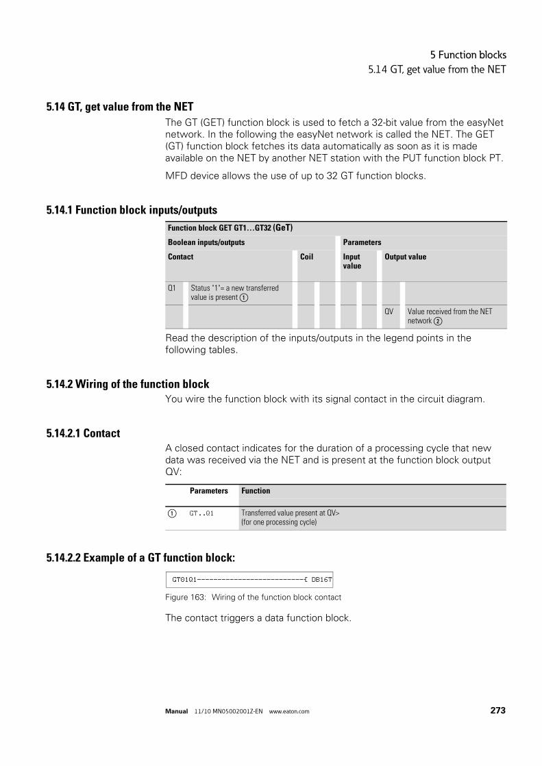
5 Function blocks
5.14 GT, get value from the NET
Manual 11/10 MN05002001Z-EN www.eaton.com 273
5.14 GT, get value from the NET
The GT (GET) function block is used to fetch a 32-bit value from the easyNet network. In the following the easyNet network is called the NET. The GET (GT) function block fetches its data automatically as soon as it is made available on the NET by another NET station with the PUT function block PT.
MFD device allows the use of up to 32 GT function blocks.
5.14.1 Function block inputs/outputs
Read the description of the inputs/outputs in the legend points in the following tables.
5.14.2 Wiring of the function blockYou wire the function block with its signal contact in the circuit diagram.
5.14.2.1 ContactA closed contact indicates for the duration of a processing cycle that new data was received via the NET and is present at the function block output QV:
5.14.2.2 Example of a GT function block:
Figure 163: Wiring of the function block contact
The contact triggers a data function block.
Function block GET GT1…GT32 (GeT)
Boolean inputs/outputs Parameters
Contact Coil Input value
Output value
Q1 Status "1"= a new transferred value is present ①
QV Value received from the NET network ②
Parameters Function
① GT..Q1 Transferred value present at QV>(for one processing cycle)
GT01Q1--------------------------Ä DB16T

5 Function blocks
5.14 GT, get value from the NET
274 Manual 11/10 MN05002001Z-EN www.eaton.com
5.14.3 Parametric programming of the function block inputs/outputs
5.14.3.1 ParametersWhen using the function block in the circuit diagram for the first time, use OK to automatically enter the general display of function block parameters, as shown in the figure on the left. Enter the function block settings here. The display contains the following elements:
The parameter set consists of:
Number of the sending station.
The NET can connect up to 8 stations that can exchange data with each other. The stations are identified by their station number. Further information on the easyNET network is provided in → Chapter 7 "The network Net“ from page 437.
Number of the send function block
The sending station has 32 function blocks for transmitting 32-bit values to the network.
Parameter Display
The display of the parameters during operation can be disabled. Additional information → section “4.9.2.1 Parameter assignment from the circuit diagram”, page 191.
This parameter is factory set to +.
GT01 02 11 +
QV>
GT01 Function block: GT, number 01
02 The number (NET-ID) of the transmitting station,possible NET IDs: 01 - 08
11 Send function block of the sending station (here PT 11), possible function block numbers: 01 - 32
+ Parameter display: Call enabled
② QV> 32 Bit value received from the NET network, Value range: -2147483648 - 2147483647
Parameters Function
+ Parameters are displayed
- Parameters are not displayed

5 Function blocks
5.14 GT, get value from the NET
Manual 11/10 MN05002001Z-EN www.eaton.com 275
Output
The output provides the value transferred via the NET for one cycle. You can assign the following operands to output …QV>:
• Analog output QA01.• Markers MD, MW, MB.
Memory requirement
The GT function block requires 28 bytes of memory.
Cycle time
5.14.3.2 GET diagnosticsThe GT function block only functions if the NET is operating correctly (→ section “9.3 Diagnostics”, page 479).
5.14.4 Function of the function block
Figure 164: Signal diagram function block GT
1: GT..Q1
2: Value on GT…QV>
mode Cycle time [μs]
- 21
→ The GT function block has the value 0 when the power supply is switched on.
1
2

5 Function blocks
5.15 HW, weekly timer
276 Manual 11/10 MN05002001Z-EN www.eaton.com
5.15 HW, weekly timer
An MFD device is provided with a real-time clock, which you can use in the circuit diagram as a weekly and year time switch.
5.15.1 Function block inputs/outputs
Read the description of the inputs/outputs in the following tables
5.15.2 FunctionMFD device allows for the use of up to 32 function blocks of type weekly timer.
For each weekly timer four switch channels A, B, C and D are available. You can choose an on and off switching time for every channel. These channels of the weekly timer all act jointly on the contact Q1 that you include in the circuit diagram. The channels are set via the parameter display or easySoft.
5.15.3 Behavior in the event of a power failureThe time and date are backed up in the event of a power supply failure and continue to run. This means that it will continue to run in the event of a power failure, although the time switch relays will not switch. The contacts are kept open when de-energized. Information on the battery back-up time are provided on → section “11.3.5 Central processing unit, real-time clock/timing relay/memory”, page 503.
→ The procedure for setting the time, → Section "8.5.1 Setting time and date“, page 464.
Weekly timer HW1…HW32 (Hora Week)
Boolean inputs/outputs Parameters
Contact Coil Input value Output value
Q1 "1" if the on condition is fulfilled ①
DY1 Weekday Switch on time ②
DY2 Weekday Switch on time ③
On and Off date ④ + ⑤
→ The electronic clock module integrated into the MFD device works with a date range of 2001-01-01 to 2099-12-31
→ The operator can change the on or off time of a channel of a weekly timer function block during operation. The values can be entered via the buttons of an MFD-CP8... device from device version 05 or via an MFD-CP10... device. For this the weekly timer entry element must be used in a screen.

5 Function blocks
5.15 HW, weekly timer
Manual 11/10 MN05002001Z-EN www.eaton.com 277
5.15.4 Wiring of the function blockThe function block is wired in the circuit diagram with its contact.
5.15.4.1 ContactThe contact of the function block is evaluated in the circuit diagram. It closes for the on time and opens for the off time on the defined days.
Example for a weekly timer:
Figure 165: Wiring of the function block contact
The weekly timer controls a device output directly.
5.15.5 Parametric programming of the function block inputs/outputs
5.15.5.1 ParametersWhen using the function block in the circuit diagram for the first time, use OK to automatically enter the general display of function block parameters, as shown in the figure on the left. The function block settings are carried out here. The display contains the following elements:
The parameter set consists of:
Parameters Function
① HW..Q1 Switching contact; closes in the defined period
HW14Q1---------------------------Ä Q 01
HW14 A +
>DY1
>DY2
>ON
>OFFHW14 Function block: Weekly timer, number 14
CSA Time switch channel: A
+ Parameter display: Call enabled
②
>DY1
Day 1: Day on which the switch-on is to occur for the first time (start of time period).
③
>DY2
Day 2: Day on which the switch-off is to occur for the last time (end of time period).
④ >ON Closing delay: 00:00 - 23:59, No on switching: --:--
⑤
>OFF
Break time: 00:00-23:59, No off switching: --:--

5 Function blocks
5.15 HW, weekly timer
278 Manual 11/10 MN05002001Z-EN www.eaton.com
Channel
For each weekly timer channels A, B, C and D are available. These channels all act jointly on the contact Q1 of the weekly timer.
Parameter Display
The display of the parameters during operation can be disabled. Additional information → section “4.9.2.1 Parameter assignment from the circuit diagram”, page 191.
This parameter is factory set to +.
Day 1 and day 2
These parameters DY1/DY2 are used to limit the period in which the output HW..Q1 is switched.
Enter either a period of several days or only of one day:
Parameters Function
CSA Display of the parameters: Channel A
B Display of the parameters: Channel B
C Display of the parameters: Channel C
D Display of the parameters: Channel D
Parameters Function
+ Parameters are displayed
- Parameters are not displayed
Entry On and off time
MO Monday
TU Tuesday
WE Wednesday
TH Thursday
FR Friday
SA Saturday
SO Sunday
-- No day

5 Function blocks
5.15 HW, weekly timer
Manual 11/10 MN05002001Z-EN www.eaton.com 279
Examples:
• Monday to Friday
• Only on MondayOn and off time
The ON/OFF parameters are used for setting the on and off time.
Memory requirement
The "weekly timer" block requires 68 bytes of memory plus 4 bytes of memory for each channel used.
Cycle time
5.15.6 Operation of the function blockThe switching points are defined according to the parameters entered.
MO to FR: on weekdays Mo, Tu, We, Th, FrON 10:00, OFF 18:00: On and off time on each weekday.
MO: Every MondayON 10:00: On timeSA: Every SaturdayOFF 18:00: Off time
Switching on working days
The weekly timer HW01 switches on from Mondays to Fridays with channel:
• A between 6:30 and 9:30.• B between 17:00 and 22:30.
HW10 A +
>DY1 MO
>DY2 FR
>ON
>OFF
HW14 D +
>DY1 MO
>DY2 --
>ON
>OFF
mode Cycle time [μs]
- 45
HW01 B +
>DY1 MO
>DY2 FR
>ON 17:00
>OFF 22:30
HW01 A +
>DY1 MO
>DY2 FR
>ON 06:30
>OFF 09:30

5 Function blocks
5.15 HW, weekly timer
280 Manual 11/10 MN05002001Z-EN www.eaton.com
Switching at the weekend
The weekly timer HW02 switches on at 16:00 on Friday and switches off at 6:00 on Monday.
Figure 166: Signal diagram of “weekend”
Overnight switching
The weekly timer HW03 switches on overnight at 22:00 Monday and switches off at 6:00 on Tuesday.
Figure 167: Signal diagram for night switching
Time overlaps
The weekly timer settings of a time switch overlap. The clock switches on at 16:00 on Monday, whereas on Tuesday and Wednesday it switches on at 10:00. The off time for Mondays to Wednesdays is 22:00.
→ If the break time is before the closing delay, MFD device will switch off on the following day.
HW02 A +
>DY1 FR
>DY2 --
>ON 16:00
>OFF --:--
HW02 B +
>DY1 MO
>DY2 --
>ON --:--
>OFF 06:00
HW03 D +
>DY1 MO
>DY2 --
>ON 22:00
>OFF 06:00
HW04 A +
>DY1 MO
>DY2 WE
>ON 16:00
>OFF 22:00
HW04 B +
>DY1 TU
>DY2 WE
>ON 10:00
>OFF 00:00

5 Function blocks
5.15 HW, weekly timer
Manual 11/10 MN05002001Z-EN www.eaton.com 281
Figure 168: Signal diagram of overlaps
Response in the event of a power failure
The power is removed between 15:00 and 17:00. The relay drops out and remains off, even after the power returns, since the first off time was at 16:00.
24 hour switching
The time switch is to switch for 24 hours. Switch on at 00:00 on Mondays and switch off at 00:00 on Tuesdays.
→ Closing delay and break time of the output Q1 always follow the channel which switches first.In other words, the first closing delay at one of the four channels switches output Q1 to 1. The first break time of a channel switches output Q1 to 0.If the on time and off time are the same, the output Q1 is switched off.
→ When it is switched on, MFD-device always updates the switching state on the basis of all the available switching time settings.
HW05 A +
>DY1 MO
>DY2 SU
>OFF 16:00
HW05 B +
>DY1 MO
>DY2 SU
>ON 12:00
>OFF 18:00
HW20 A +
>DY1 MO
>DY2
>ON 00:00
>OFF
HW20 B +
>DY1 TU
>DY2
>ON
>OFF 00:00

5 Function blocks
5.16 HY - Year Time Switch
282 Manual 11/10 MN05002001Z-EN www.eaton.com
5.16 HY - Year Time Switch
An MFD device is fitted with a real-time clock that you can use in the circuit diagram as a year and weekly timer.
Read the description of the inputs/outputs in the following tables
5.16.1 FunctionIf you have to implement special on and off switching functions on public holidays, vacations, company holidays, school holidays and special events, these can be implemented easily with the year time switch.
MFD device allows for the use of up to 32 function blocks of type year time switch.
For each year time switch four channels A, B, C and D are available. You can choose an on and off switching time for every channel. These channels of a year time switch all act jointly on the contact Q1 that you include in the circuit diagram. The channels are set via the parameter display or easySoft.
The year time switch can:
• Switch at recurring intervals by switching on and off for individual days, months, or years.
• Switch for continuous periods of time by remaining continuously switched on from the start of any user-defined day until the end of any user-defined day, month, or year.
→ The procedure for setting the time → section “8.5.1 Setting time and date”, page 464.
Year time switch HY1…HY32 (Hora Year)
Boolean inputs/outputs Parameters
Contact Coil Input value Output value
Q1 "1" if the on condition is fulfilled ①
On/off date ② + ③
→ The parameters for the switch-on and switch-off times for recurring intervals are configured in one single channel for each.The parameters for the switch-on and switch-off times for a continuous period of time are configured in two neighbouring channels. If you enter the ON information on channel A, the OFF information must be entered on channel B; likewise, if the ON information is on channel B, the OFF information must be on channel C.

5 Function blocks
5.16 HY - Year Time Switch
Manual 11/10 MN05002001Z-EN www.eaton.com 283
5.16.2 Behavior in the event of a power failureThe time and date are backed up in the event of a power supply failure and continue to run. This means that it will continue to run in the event of a power failure, although the time switch relays will not switch. The contacts are kept open when de-energized. Information on the battery back-up time are provided on → section “11.3.5 Central processing unit, real-time clock/timing relay/memory”, page 503.
5.16.3 Wiring of the function blockThe function block is wired in the circuit diagram with its contact.
5.16.3.1 ContactThe contact closes each day for the on time and opens for the off time.
5.16.3.2 Example for a year time switch:
Figure 169: Wiring of the function block contact
The year time switch controls a device output directly.
5.16.4 Parametric programming of the function block inputs/outputs
5.16.4.1 ParametersWhen using the function block in the circuit diagram for the first time, use OK to automatically enter the general display of function block parameters, as shown in the figure on the left. Enter the function block settings here. The display contains the following elements:
→ The electronic clock module integrated into the MFD device works with a date range of 2001-01-01 to 2099-12-31
→ The user can change the on and off time of a channel of the year time switch function block during operation. The values can be entered via the buttons of an MFD-CP8... device from device version 05 or an MFD-CP10... device. For this the entry element (→ section “6.4.21 Year time switch entry”, page 414) must be used in a screen.
Parameters Function
① HY..Q1 Switching contact; closes in the defined period
HY14Q1---------------------------Ä Q 01
HY14 B +
>ON
>OFF

5 Function blocks
5.16 HY - Year Time Switch
284 Manual 11/10 MN05002001Z-EN www.eaton.com
The parameter set consists of:
Channel
For each year time switch function block, you can configure the parameters for the A, B, C, and D channels that act jointly on contact Q1 of this function block.
Parameter Display
The display of the parameters during operation can be disabled. Additional information → section “4.9.2.1 Parameter assignment from the circuit diagram”, page 191.
This parameter is factory set to +.
On and off date
Use these parameters to set the data for on and off switching in the format DD.MM.YY.
5.16.4.2 ExampleDay.Month.Year: 11.11.07
5.16.4.3 Memory requirementThe year time switch function block requires 68 bytes of memory plus 4 bytes of memory for each channel used.
HY14 Function block: Year time switch, number 14
B Time switch channel: B
+ Parameter display: Call enabled
② >ON On date
③ >OFF Off date
Parameters Function
CSA Display of the parameters: Channel A
B Display of the parameters: Channel B
C Display of the parameters: Channel C
D Display of the parameters: Channel D
Parameters Function
+ Parameters are displayed
- Parameters are not displayed
Parameters Function
>ON On date
>OFF Off date

5 Function blocks
5.16 HY - Year Time Switch
Manual 11/10 MN05002001Z-EN www.eaton.com 285
5.16.4.4 Cycle time
5.16.5 How the function block worksThe year time switch can switch ranges, individual days, months, years or combinations of all three.
Years
Switching at 00:00:
• On on 01.01.2008 and• Off on 01.01.2013.Months
Switching at 00:00:
• On on 01 April every year.• Off on 01 November every year.Days
Switching at 00:00:
• On on the 2nd day of every month.• On on the 26th day of every month.
5.16.6 Entry rulesThe contact switches (ON to OFF)
• in the years.• in the defined months.• on the entered days.
mode Cycle time [μs]
- 61
HY01 A +
>ON --.--.08
>OFF --.--.12
HY01 A +
>ON --.04.--
>OFF --.10.--
HY01 A +
>ON 02.--.--
>OFF 25.--.--
CAUTION
The year time switch only operates correctly if you observe the following rules:• The On year must be before the Off year, • ON and OFF times must be specified the same in pairs, for
example: • ON = Day/--/--, OFF = Day/--/-- • ON = --/--/Year, OFF = --/--/Year, • ON = --/Month/Year, OFF = --/Month/Year • ON = Day/Month/Year, OFF = Day/Month/Year
• Normally, the ON day should be before the OFF day; otherwise, the exception described on Example 8 (→ section “ Example 8: Selecting a time range of two days spanning the turn of the year (2-channel)”, page 289) on applies.

5 Function blocks
5.16 HY - Year Time Switch
286 Manual 11/10 MN05002001Z-EN www.eaton.com
The following nine entry rules are possible (XX = position used)
Rule 1
ON: Day
OFF: Day
Rule 2
ON: Month
OFF: Month
Rule 3
ON: Year
OFF: Year
Rule 4
ON: Day/month
OFF: Day/month
Rule 5
ON: Month/year
OFF: Month/year
Rule 6
ON: Day/month/year
OFF: Day/month/year
Rule 7
Two-channel
Channel A ON: Day/month
Channel B OFF: Day/month
Rule 8
Two-channel
Channel C ON: Day/Month/Year
Channel D OFF: Day/month/year
With this rule, the same year number must be entered in each channel in the ON and OFF entry area.
Rule 9
Overlapping channels: The first ON date switches on and the first OFF date switches off.
HY01 A +
>ON XX.--.--
>OFF XX.--.--
HY01 A +
>ON --.XX.--
>OFF --.XX.--
HY01 A +
>ON --.--.XX
>ON --.--.XX
HY01 A +
>ON XX.XX.--
>OFF XX.XX.--
HY01 A +
>ON --.XX.XX
>OFF --.XX.XX
HY01 A +
>ON XX.XX.XX
>OFF XX.XX.XX
HY01 A +
>ON XX.XX.--
>OFF --.--.--
HY01 B +
>ON --.--.--
>OFF XX.XX.--
HY01 C +
>ON XX.XX.XX
>OFF --.--.XX
HY01 D +
>ON --.--.XX
>ON --.--.XX

5 Function blocks
5.16 HY - Year Time Switch
Manual 11/10 MN05002001Z-EN www.eaton.com 287
5.16.7 Sample parameter configurations
5.16.7.1 Configuring the parameters for recurring intervalsExample 1: Selecting year range (1-channel)
The year time switch HY1 is required to switch on at 00:00 on January 1 2010 and stay on until 00:00 January 1 2012.
Figure 170: Select year range
Example 2: Selecting month ranges (1-channel)
The year time switch HY02 is required to switch on at 00:00 on March 1 and stay on until 00:00 October 1.
Figure 171: Select month range
Example 3:Selecting day ranges (1-channel)
The year time switch HY03 is required to switch on at 00:00 on day 1 of each month and switch off at 00:00 on day 29 of each month.
Figure 172: Select day range
Example 4: Selecting public holidays (1-channel)
The year time switch HY04 is required to switch on at 00:00 on day 25.12 of each year and switch off at 00:00 on day 27.12 of each year, “Christmas program”.
Figure 173: Select public holiday
Example 5: Specific days of specific months (1-channel)
The year time switch HY05 is required to switch on at 0:00 on day 9 of months 6, 7, 8, 9 and 10 of each year and switch off at 00:00 on day 17 of the month.
HY01 A +
>ON --.--.10
>OFF --.--.11
1/1 31/12
2009 2010 2011 2012
HY02 A +
>ON __.03.-- >OFF --.09.--
1/3 30/9
... 2010 2011
1/3 30/9 1/3 30/9 1/3
2012 2013 ...
HY03 A +
>ON 01.--.--
>OFF 28.--.--
1
28 28 28
1 1 1
Jan Feb Mar Apr
HY04 A +
>ON 25.12.--
>OFF 26.12.--
26/12
... 2010 2011
26/12 26/12
25 25 25
2012 2013 ...
HY05 A +
>ON 09.06.--
>OFF 16.10.--

5 Function blocks
5.16 HY - Year Time Switch
288 Manual 11/10 MN05002001Z-EN www.eaton.com
Figure 174: Chose specific days of specific months
5.16.7.2 Configuring the parameters for continuous periods of timeThe following examples show how to configure the parameters for continuous periods of time in which the time switch remains continuously switched on. The parameter definition is carried out in pairs on two adjacent channels.
Example 6: Time range for each year (2-channel)
The year time switch HY01 is required to switch on at 00:00 on day 02.05 of each year and stay on continuously until 00:00 on 1.11 of each year, "Open air season".
Figure 175: Select time range for each year
Parameter settings of the year time switch HY01:
ON/OFF: First/last switch-on years are not restricted in this case.
ON/OFF: First/last switch-off years are not restricted in this case.
Example 7: Selecting a time range for a limited number of years (2-channel)
The HY01 year time switch should switch on at 00:00, on 05/02, in the years 2011 and 2012, and remain switched on until 00:00 on 11/1 in each case.
Figure 176: Select a time range for a limited number of years
Parameter settings of the year time switch HY01:
16 16 16
9 9 9
... Jul Aug Sep ...
31/10
... 2010 2011
31/10 31/10 31/10
2/5 2/5 2/5
2012 ...
HY01 A +
>ON 02.05.--
>OFF --.--.--
HY01 B +
>ON --.--.--
>OFF 31.10.--
31/10
20112010 2012
31/10
2/5 2/5
2013

5 Function blocks
5.16 HY - Year Time Switch
Manual 11/10 MN05002001Z-EN www.eaton.com 289
ON/OFF: First/last switch-on year.
ON/OFF: First/last switch-off year.
Example 8: Selecting a time range of two days spanning the turn of the year (2-channel)
The HY01 year time switch should switch on at 00:00 on 12/31 of every year and remain continuously switched on until 00:00 on 02/01 of every year.
Figure 177: Select a time range of two days spanning the turn of the year
Parameter settings of the year time switch HY01:
ON/OFF: First/last switch-on years are not restricted in this case.
ON/OFF: First/last switch-off years are not restricted in this case.
Example 9: Selecting a time range of two days spanning the turn of the year on 2010/2011, 2011/2012 (2-channel)
The HY01 year time switch should switch on at 00:00 on 12/31 of 2010 and remain switched on until 00:00 on 01/02 of 2011, and switch on at 00:00 on 12/31 of 2011 and remain switched on until 00:00 on 01/02 of 2012.
Figure 178: Select a time range of two days spanning the turn of the year
HY01 A +
>ON 02.05.11
>OFF --.--.12
HY01 B +
>ON --.--.11
>OFF 31.10.12
1/1
... 2010 2011
1/1 1/1
3112
1/1
3112
3112
3112
2012 ...
HY01 A +
>ON 31.12.--
>OFF --.--.--
HY01 B +
>ON --.--.--
>OFF 01.01.--
1/1
2010 2011
1/1
3112
3112
2012

5 Function blocks
5.16 HY - Year Time Switch
290 Manual 11/10 MN05002001Z-EN www.eaton.com
Parameter settings of the year time switch HY01:
ON/OFF: First/last switch-on year.
ON/OFF: First/last switch-off year.
Example 10: Overlapping time ranges (2-channel)
This example shows how to configure the parameters for continuous overlapping time ranges on adjacent channels.
The HY01 year time switch, channel C, switches on at 00:00 on the third of months 5, 6, 7, 8, 9, 10 and remains switched on until 00:00 on the 26th of these months.
The HY01 year time switch, channel D, switches on at 00:00 on the second of months 6, 7, 8, 9, 10, 11, 12 and remains switched on until 00:00 on the 18th of these months.
Total result corresponding to the channel configurations and behavior of contact Q1 in this example:
The time switch switches on at 00:00 on 3 May and stays on until 00:00 on 26 May.In June, July, August, September, October, the time switch will switch on at 00:00 on day 2 of the month and switch off at 00:00 on day 18.In November and December, the time switch will switch on at 00:00 on the second of the month and switch off until 00:00 on the 18th. The following note explains this switching behavior.
HY01 A +
>ON 31.12.10
>OFF --.--.11
HY01 B +
>ON --.--.11
>OFF 01.01.12
Parameter settings of the year time switch Y01
→ Switching behaviour with overlapping channel settings:If parameterized ranges overlap, the year time switch switches the contact on with the first detected ON, irrespective of which channel supplies this ON signal. In the same way, the year time switch switches the contact off with the first detected OFF, irrespective of whether another channel still supplies the ON signal!
HY01
C +
ON 03.05.--
OFF 25.10.--
①
HY01
D +
ON 02.06.--
OFF 17.12.--
②

5 Function blocks
5.17 JC, conditional jump
Manual 11/10 MN05002001Z-EN www.eaton.com 291
5.17 JC, conditional jump
With function block JC.. you can branch off forwards to a jump label (Label, LB) within the function block list to skip several function blocks.
You use LB.. (jump label) as the jump destination. The JC and LB function blocks are used in the circuit diagram.
MFD device allows up to 32 conditional jumps.
5.17.1 Function block inputs/outputs
Read the description of the inputs/outputs in the legend points in the following tables.
5.17.2 Wiring of the function blockYou wire the function block in the circuit diagram with its enable coil JC..EN. It can be wired directly to the device terminals I1 to I12 or associated internally.
5.17.2.1 Coil
→ For each JC.. function block, an LB.. function block must be provided as the jump label. The JC.. and LB.. function blocks must always be used in pairs. JC01 is always assigned the jump label LB01.
→ The description of the LB.. function block is provided on → section “5.18 LB, jump label”, page 294.
Arithmetic JC1…JC32 (Jump Conditional)
Boolean inputs/outputs Parameters
Contact Coil Input value Output value
E1 Error output ①
EN EN=1 -> activation of jump function ②
Parameters Function
② JC..EN Activation of the function block

5 Function blocks
5.17 JC, conditional jump
292 Manual 11/10 MN05002001Z-EN www.eaton.com
5.17.2.2 ContactThe contact indicates a fault if there is not an associated jump present or is in front of the jump location (backward jump).
5.17.2.3 Example of a conditional jump:
Figure 179: Wiring the enable coil
5.17.3 Parametric programming of the function block inputs/outputs
5.17.3.1 ParametersWhen using the function block in the circuit diagram for the first time, use OK to automatically enter the general display of function block parameters, as shown in the figure on the left. Enter the function block settings here. The display contains the following elements:
5.17.3.2 Memory requirementThe conditional jump function block requires 20 bytes of memory.
5.17.4 Function of the function blockIf the JC..EN enable coil is active, the program jumps forwards over one or several function blocks. The next function block to be processed is then the first to follow the LB jump label in the function block diagram. If the JC..EN enable coil is not active, the program is processing the next function block that is added in the function block diagram behind JC...
In the function block list a jump label must be positioned downstream, i.e. towards the end of the list when viewed from associated function block “conditional jump”. If it is placed in front of the associated jump location (backward jump), the program branches to the end of the function block list and fault contact JC..E1 of function block “conditional jump” closes. If no associated jump label is set in the function block list, the program jumps to the end of the list and fault contact JC..E1 also closes.
Parameters Function
① JC..E1 Error message
IS01 ---------------------------Ä JC01EN
JC01 +
JC01 Function block: Conditional jump, number 01
+ Without function

5 Function blocks
5.17 JC, conditional jump
Manual 11/10 MN05002001Z-EN www.eaton.com 293
5.17.4.1 ExampleA jump is to be made downstream of a table function block TB01 when marker M01 has the state 1.
Figure 180: Example of conditional jump
Enter the function block editor via <PROGRAM..., PROGRAM -> FUNCTION RELAYS>.
In this menu use the cursor buttons ÍÚ to move to the location from where the jump is to be made and press OK.
Then use the cursor keys ÍÚ to select function block JC01 and close the input dialog with two clicks on OK.
Insert table function block TB01 into then next position in the function block list, configure it and complete your input with ESC.
Use the cursor buttons ÍÚ to navigate to the next position in the function block list and insert the jump label LB01 described below there.
During processing, the program branches to jump label LB01 for as long as JC01EN is 1.
M 01---------------------------Ä JC01EN
JC01 +
TB01 -
LB01
L:031 B:6488
→ For subsequently inserting function block JC.. in the function block list to skip other, existing function blocks, the use of the easySoft-Pro programming software is recommended. This software allows function blocks to be moved into any position.
→ For subsequently inserting function block JC.. in the function block list to skip other, existing function blocks, the use of the easySoft programming software is recommended. This software allows function blocks to be moved into any position.

5 Function blocks
5.18 LB, jump label
294 Manual 11/10 MN05002001Z-EN www.eaton.com
5.18 LB, jump label
Within the function block list jump label LB.. is the jump target for a conditional jump with function block JC.. . The function blocks JC and LB are always used in pairs in the circuit diagram.
MFD device allows the use of up to 32 jump labels.
5.18.0.1 Function BlockAs the LB.. function block is simply only a jump destination, it does not require any association or parameters in the circuit diagram. It does not have any coils or contacts and is simply placed at the required position in the function block list.
In the function block list a jump label must be positioned downstream, i.e. towards the end of the list when viewed from associated function block “conditional jump”. If it is placed in front of the associated jump location (backward jump), the program branches to the end of the function block list and fault contact JC..E1 of function block “conditional jump” closes. If no associated jump label is set in the function block list, the program jumps to the end of the list and fault contact JC..E1 also closes.
Enter the function block editor from the main menu via <PROGRAM... -> PROGRAM -> FUNCTION RELAYS>.
In this menu use the cursor buttons ÍÚ to move to the location to which the jump is to be made and press OK.
Then use the cursor keys ÍÚ to select function block LB.. and close the input dialog with two clicks on OK.
The description of the JC.. conditional jump function block is provided in → Chapter 5 "Function blocks“ from page 291. This also contains an example.
→ A corresponding JC.. function block (conditional jump) must exist for every LB.. function block. For example, the jump label LB01 belongs to the conditional jump JC01.
5 Function blocks
5.19 LS, value scaling
Manual 11/10 MN05002001Z-EN www.eaton.com 295
5.19 LS, value scaling
The function block enables you to convert values from one value range to another one.
The function block scales values at input LS..I1 according to the mathematical relationship you have set, and then outputs the result as a larger or smaller value at the output at LS..QV. The mathematical relationship is based on a straight line defined by the coordinate pairs X1, Y1 and X2, Y2 (see under “The mathematical relationship is:”).
A typical application is the conversion of values, such as 0…20 mA to 4…20 mA. A MFD device is provided with 32 value scaling function blocks.
5.19.1 Function block inputs/outputs
Read the description of the inputs/outputs in the legend points in the following tables.
5.19.2 Wiring of the function blockYou wire the function block in the circuit diagram with an enable coil.
5.19.2.1 CoilThe enable coil LS..EN activates the function block in the standard circuit diagram; when the coil is deactivated, the output QV> is set to 0.
Value scaling LS01…LS32 (Linear Scaling)
Boolean inputs/outputs Parameters
Contact Coil Input value Output value
EN Activate the function block ①
I1 Input value ②
X1 Support point 1 ③
Y1 Support point 2 ④
X2 Support point 1 ⑤
Y2 Support point 1 ⑥
QV Scaled output value ⑦
Parameters Function
① LS..EN Enables the function block

5 Function blocks
5.19 LS, value scaling
296 Manual 11/10 MN05002001Z-EN www.eaton.com
5.19.2.2 Example of a value scaling function block
Figure 181: MFD circuit diagram with enabling of value scaling function block
5.19.3 Parametric programming of the function block inputs/outputs
5.19.3.1 ParametersWhen using the function block in the circuit diagram for the first time, use OK to automatically enter the general display of function block parameters, as shown in the figure on the left. Enter the function block settings here. The display contains the following elements:
Parameter Display
The display of the parameters during operation can be disabled. Additional information → section “4.9.2.1 Parameter assignment from the circuit diagram”, page 191.
This parameter is factory set to +.
Inputs
>I1: Assign the unscaled value to function block input >I1.
>X1 and >Y1: You define the first support point of the straight line at function block inputs >X1 and >Y1.
>X2 and >Y21: The second pair of values at function block inputs >X2 and >Y2 determines the second support point of the straight line.
You can assign the following operands to function block inputs >I1, >X1, >Y1, >X2 and >Y2:
I 05--------------------------Ä LS01EN
LS01 +
>I1
>X1
>Y1
>X2
>Y2
QV>
LS01 Function block: Value scaling, number 01Value range: -2147483648 - 2147483647, valid for all values.
+ Parameter display: Call enabled
② >I1 Input value
③ >X1 Lower value of source range,
④ >Y1 Lower value of target range
⑤ >X2 Upper value of source range
⑥ >Y2 Upper value of target range
⑦ QV> Output value, scaled
Parameters Function
+ Parameters are displayed
- Parameters are not displayed

5 Function blocks
5.19 LS, value scaling
Manual 11/10 MN05002001Z-EN www.eaton.com 297
• Constant• Markers MD, MW, MB• Analog inputs IA01 to IA04:
• IA01: Terminal I7• IA02: Terminal I8• IA03: Terminal I11• IA04: Terminal I12
• Analog output QA01• Output …QV> of a different function block
Output
The output QV> supplies the scaled value as an integer.
You can assign the following operands:
• Markers MD, MW, MB• Analog output QA01
Memory requirement
The function block requires 64 bytes of memory plus 4 bytes per constant at the input.
Cycle time
5.19.4 Function of the function block
Figure 182: Value scaling function block – reduce value range
a Source Range
b Destination Range
mode Cycle time [μs]
- 224
→ The scaling function block must be enabled via coil LS..EN = 1 in order for it to work. If the coil LS..EN is not active, the entire function block is deactivated and reset. The output value is set to zero.
a
b
Y1 Y2
X1 X2

5 Function blocks
5.19 LS, value scaling
298 Manual 11/10 MN05002001Z-EN www.eaton.com
Figure 183: Function block value scaling - increasing value range
a Source Range
b Destination Range
The mathematical relationship is follows:
• Y = m x X + Y0• m = (Y2 - Y1) / (X2 - X1)• Y0 = ((X2 x Y1) - (X1 x Y2)) / (X2 - X1)m = gradient
Y0 = Y offset when X = 0
X1, Y1 = First value pair
X2, Y2 = Second value pair
g = Straight line with positive gradient
Figure 184: Mathematical interrelationship
a
b
Y1 Y2
X1 X2
X1
Y1
Y2
X2X0
Y0
g

5 Function blocks
5.19 LS, value scaling
Manual 11/10 MN05002001Z-EN www.eaton.com 299
5.19.5 Application exampleThe signal of measuring value converters with a current output reaches the input LS..I1 of the scaling function block via the output of a multiplexer function block. The measuring value is between:
• 4 mA, corresponds to measured value 0 and• 20 mA, corresponds to maximum measured value.
The task of the function block is to adjust the value in order to show it at output LS..QV as a value between 0 and 100 %.
The transferred measured value has a resolution between 0…1023 bits. This means:
• The minimum measured value is 1023 bits x 4 mA / 20mA = 205 bit.• The maximum measured value is at 1023 bits.
The parameter display and the parameter set for function block LS01 is shown on the left. After the function block number 01 is defined, you enter here the following values:
• the operand MX01QV with the value to be scaled.• the first support point of the straight line with its zero point coordinates:
• X1 = 205• Y1 = 0 and
• the second support point of the straight line with its maximum point coordinates:• X1 = 1023• Y1 = 100
• the transfer marker MD01 with the scaled value.
LS01 +
>I1 MX01QV
>X1 +205
>Y1 +0
>X2 +1023
>Y2 +100
QV> MD01

5 Function blocks
5.20 MR, master reset
300 Manual 11/10 MN05002001Z-EN www.eaton.com
5.20 MR, master reset
The master reset function block allows you to reset the states of the markers and all outputs to 0 with a single command. The operating mode of the function block allows you to set whether only the outputs, only the markers or outputs and markers are to be reset.
MFD device allows the use of up to 32 master reset function blocks.
5.20.1 Function block inputs/outputs
Read the description of the inputs/outputs in the legend points in the following tables.
5.20.2 Wiring of the function blockYou wire the function block in the circuit diagram with its trigger coil.
5.20.2.1 Coil
5.20.2.2 ContactA closed contact indicates:
Master reset MR1…MR32 (Master Reset)
Boolean inputs/outputs Parameters
Contact Coil Input value Output value
Q1 Trigger confirmation ①
T_ Trigger Signal ②
Parameters Function
② MR..T_ Function block reset on rising edge
Parameters Function
① MR..Q1 1 on activated trigger signal
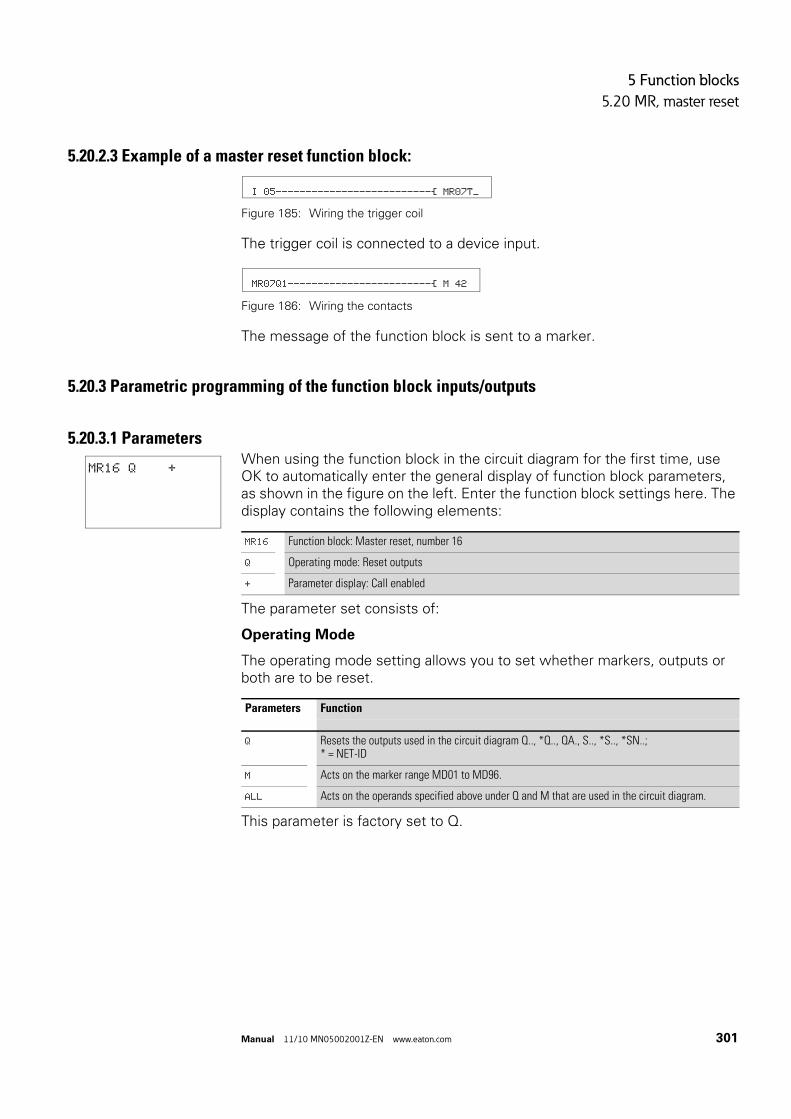
5 Function blocks
5.20 MR, master reset
Manual 11/10 MN05002001Z-EN www.eaton.com 301
5.20.2.3 Example of a master reset function block:
Figure 185: Wiring the trigger coil
The trigger coil is connected to a device input.
Figure 186: Wiring the contacts
The message of the function block is sent to a marker.
5.20.3 Parametric programming of the function block inputs/outputs
5.20.3.1 ParametersWhen using the function block in the circuit diagram for the first time, use OK to automatically enter the general display of function block parameters, as shown in the figure on the left. Enter the function block settings here. The display contains the following elements:
The parameter set consists of:
Operating Mode
The operating mode setting allows you to set whether markers, outputs or both are to be reset.
This parameter is factory set to Q.
I 05--------------------------Ä MR07T_
MR07Q1------------------------Ä M 42
MR16 Q +
MR16 Function block: Master reset, number 16
Q Operating mode: Reset outputs
+ Parameter display: Call enabled
Parameters Function
Q Resets the outputs used in the circuit diagram Q.., *Q.., QA., S.., *S.., *SN..;* = NET-ID
M Acts on the marker range MD01 to MD96.
ALL Acts on the operands specified above under Q and M that are used in the circuit diagram.

5 Function blocks
5.20 MR, master reset
302 Manual 11/10 MN05002001Z-EN www.eaton.com
Parameter Display
The display of the parameters during operation can be disabled. Additional information → section “4.9.2.1 Parameter assignment from the circuit diagram”, page 191.
This parameter is factory set to +.
Memory requirement
The master reset function block requires 20 bytes of memory.
Cycle time
5.20.4 Function of the function blockAll outputs or the markers are set to 0 in accordance with the operating mode when a rising edge is detected on the trigger coil.
The contact MR1..Q1 assumes the state of its own trigger coil and confirms the reset operation.
Parameters Function
+ Parameters are displayed
- Parameters are not displayed
mode Cycle time [μs]
Q 47
M 185
ALL 217
→ Carry out the master reset function block so that all data ranges are cleared reliably. Otherwise subsequent function blocks may overwrite the data ranges.

5 Function blocks
5.21 MX, data multiplexer
Manual 11/10 MN05002001Z-EN www.eaton.com 303
5.21 MX, data multiplexer
This function block is available for easy800 from device version 07 and for MFD-CP10... devices. The data multiplexer function block allows you to select a value from eight input values MX..I1 to MX..I8 as if using a mode selector switch. The function block provides this value after transferring it to its output MX..QV.
A MFD device allows the use of up to 32 data multiplexers.
5.21.1 Function block inputs/outputs
Read the description of the inputs/outputs in the legend points in the following tables.
5.21.2 Wiring of the function blockThe function block is enabled via the coil in the circuit diagram and its contact is then queried as an error output.
5.21.2.1 CoilWhen the enable coil MX..EN is set to 1, it switches the selected input Ix to output QV. This switch operation is retained for as long as MX..EN is 1. When the MX..EN state changes from 1 to 0, output QV is reset to 0.
5.21.2.2 ContactA closed contact indicates a filter:
Data multiplexer MX01…MX32 (MultipleXer)
Boolean inputs/outputs Parameters
Contact Coil Input value Output value
E1 Error output ①
EN Activation of the function block ②
K Channel number ③
I1-I8
Input value, channel 1-8 ④
QV Output value of the selected channel ⑤
Parameters Function
② MX..EN Enables the function block
Parameters Function
① MX..E1 Fault, e.g. invalid channel setting

5 Function blocks
5.21 MX, data multiplexer
304 Manual 11/10 MN05002001Z-EN www.eaton.com
5.21.2.3 Example
Figure 187: Wiring the enable coil
Its coil MX01EN is directly connected to the device terminal I05.
Figure 188: Wiring of the function block contact MX01E1
The function block contact MX01E1 (fault message) is associated with the marker M12.
5.21.3 Parametric programming of the function block inputs/outputs
5.21.3.1 ParametersWhen using the function block in the circuit diagram for the first time, press OK to enter the general display of the function block parameters automatically, as shown in the figure on the left for an on-delayed timing relay. Enter the function block settings here. The display contains the following elements:
The parameter set consists of:
Parameter Display
The display of the parameters during operation can be disabled. Further information on this is provided → Section "4.9.2.1 Parameter assignment from the circuit diagram“ on page 191.
This parameter is factory set to +.
Inputs
>K: Function block input >K is used to define the input channel to be supplied at function block output QV>.
>I1 to >I8: Assign the values to function block inputs >I1 to >I8 that you wish to output on function block output QV>.
I 05--------------------------Ä MX01EN
MX01E1---------------------------Ä M 12
MX01 +
>K
>I1
>I2
>I3
>I4
>I5
>I6
>I7
>I8
QV>
MX01 Function block; Data multiplexer, number 01
+ Parameter display: Call enabled
③ >K Channel number (0 - 7)
④ >I1
>I8
Input channels I1 to I8, value range:- 2147483648 - 2147483647
⑤ QV> Supplies the selected input value
Parameters Function
+ Parameters are displayed
- Parameters are not displayed

5 Function blocks
5.21 MX, data multiplexer
Manual 11/10 MN05002001Z-EN www.eaton.com 305
You can assign the following operands to the function block inputs >K and >I1 to >I8:
• Constant.• Markers MD, MW, MB.• Analog inputs IA01 to IA04:
• IA01: Terminal I7.• IA02: Terminal I8.• IA03: Terminal I11.• IA04: Terminal I12.
• Analog output QA01.• Output …QV> of a different function block.
Output
The output QV> supplies the value present at the selected input channel.
You can assign the following operands to output MX..QV:
• Analog output QA01.• Markers MD, MW, MB.
Memory requirement
The data multiplexer function block requires 96 bytes of memory plus 4 bytes per constant at the function block inputs.
5.21.4 Function of the function blockThe multiplexer is active if the Enable coil MX..EN is set to 1.
You use the channel number input MX..K to set which input is to be switched through to the output. The channel number input switches the input values in their order, i.e.:
• Channel number 0 supplies the input MX..I1 to MX..QV.• Channel number 7 supplies the input MX..I8 to MX..QV.
You can also change the channel number when the EN input is set.
When EN = 1, the value at the selected input Ix is continuously output and refreshed with every processing cycle.
The fault contact MX..E1 closes if an invalid parameter is present at the channel number input MX..K.

5 Function blocks
5.21 MX, data multiplexer
306 Manual 11/10 MN05002001Z-EN www.eaton.com
5.21.4.1 Example A drive is required to run at a fixed speed and at three dependent speeds.
It receives the setting from a multiplexer function block.
MB08 defines the number of the channel that is to reach the output. The fixed speed is set as a constant at input MX01I1, the subsequent inputs are assigned the variable values from markers MB01 to MB03. The setpoints at output MX01QV of the function block are output at MB04.
The function block is first activated in the circuit diagram by marker M33. The following figure shows the the association.L
Figure 189: Circuit diagram for enabling the data multiplexer function block
Enter the parameters of the function block as shown on the left.
M 33---------------------------Ä MX01EN
MX01 +
>K MB08
>I1 +40
>I2 MB01
>I3 MB02
>I4 MB03
>I5
>I6
>I7
>I8
QV> MB04

5 Function blocks
5.22 NC, numerical converter
Manual 11/10 MN05002001Z-EN www.eaton.com 307
5.22 NC, numerical converter
The numerical converter function block is used to convert a value of:
• BCD in binary value.• Binary value in BCD.
The binary value is further processed in the device. For example it can be added to a value. The binary value is displayed in the simulator as a decimal value. MFD device allows the use of up to 32 numerical converters.
5.22.1 Function block inputs/outputs
Read the description of the inputs/outputs in the legend points in the following tables.
5.22.2 Wiring of the function blockThe function block is enabled in the circuit diagram.
5.22.2.1 CoilCoil NC..EN is used to activate the function block. If the coil NC..EN is not active, the entire function block is deactivated and reset. The output value is set to zero.
5.22.2.2 Example:
Figure 190: Wiring the enable coil
Its coil NC..EN is directly connected to the device terminal IS5.
Numerical converter NC1…NC32 (Numeric Coding)
Boolean inputs/outputs Parameters
Contact Coil Input value Output value
EN Activation of the function block ①
I1 Value to be converted ②
QV Converted value ③
Parameters Function
① NC..EN Enables the function block
I 05--------------------------Ä NC01EN

5 Function blocks
5.22 NC, numerical converter
308 Manual 11/10 MN05002001Z-EN www.eaton.com
5.22.3 Parametric programming of the function block inputs/outputs
5.22.3.1 Parameters
The parameter set consists of:
Operating Mode
The operating mode determines whether a binary value is to be converted to BCD or vice versa.
The factory setting of this parameter is BCD.
Parameter Display
The display of the parameters during operation can be disabled. Additional information → section “4.9.2.1 Parameter assignment from the circuit diagram”, page 191.
This parameter is factory set to +.
5.22.3.2 Number range of the BCD codeThe BCD code only allows the number range 0.to 9. Values greater than 9 are processed as 9.
NC02 BCD +
>I1
QV>
NC02 Function block; Numerical converter, number 02
BCD Operating mode: Converting BCD to binary
+ Parameter display: Call enabled
② >I1 Input value: Decimal: -161061273 - +161061273BCD: -9999999 - +9999999
③ QV> Output value:Decimal: -161061273 - +161061273BCD: -9999999 - +9999999
Parameters Function, parameterization in the function block
BCD Converting BCD to binary
BIN Converting binary to BCD
Parameters Function
+ Parameters are displayed
- Parameters are not displayed
BCD code Decimal value
0000 0
0001 1
0010 2
0011 3

5 Function blocks
5.22 NC, numerical converter
Manual 11/10 MN05002001Z-EN www.eaton.com 309
Input
Assign the input value to be converted to function block input >I1.
The function block input >I1 can be assigned the following operands:
• Constant.• Markers MD, MW, MB.• Analog inputs IA01 to IA04:
• IA01: Terminal I7.• IA02: Terminal I8.• IA03: Terminal I11.• IA04: Terminal I12.
• Analog output QA01.• Output …QV> of a different function block.
Output
Output QV> supplies the converted value.
You can assign the following operands to the function block output NC..QV :
• Analog output QA01.• Markers MD, MW, MB.
Memory requirement
The numerical converter function block requires 32 bytes of memory plus 4 bytes per constant at the function block input.
Cycle time
0100 4
0101 5
0110 6
0111 7
1000 8
1001 9
1010 - 1111 Not permissible
mode Cycle time [μs]
BCD 34
BIN 127
BCD code Decimal value

5 Function blocks
5.22 NC, numerical converter
310 Manual 11/10 MN05002001Z-EN www.eaton.com
5.22.4 Function of the function block
5.22.4.1 BCD operating modeThe BCD value present at input I1 is converted to a binary value and supplied on the output QV>. The binary value is displayed as a decimal value.
Example 1:
• Input value >I1: +9dec
• Binary value: 1001• Decimal value QV>: + 9
Example 2:
• Input value >I1: +14dec
• Binary value: 1110• Decimal value QV>: + 9
Example 3:
• Input value >I1: 19dec
• Binary value: 00010011• Decimal value QV>: 13
Example 4:
• Input value >I1: 161061273dec
• Binary value: 1001100110011001100110011001• Decimal value QV>: 9999999
Example 5:
• Input value >I1: -61673dec
• Binary value: 10000000000000001111000011101001• Decimal value QV>: -9099
Example 6:
• Input value >I1: 2147483647dec
• Binary value: 01111111111111111111111111111111• Decimal value QV>: 9999999
BIN operating mode
The binary value present at input >I1 is converted to a BCD value and supplied at the output QV>. The binary value is displayed as a decimal value.
→ Bit 32 is the sign bit. Bit 32 = 1 → Sign = Minus.
→ Values greater than 161061273 are output as 9999999. Values less than –161061273 are output as –9999999. The working range of the function block has been exceeded.
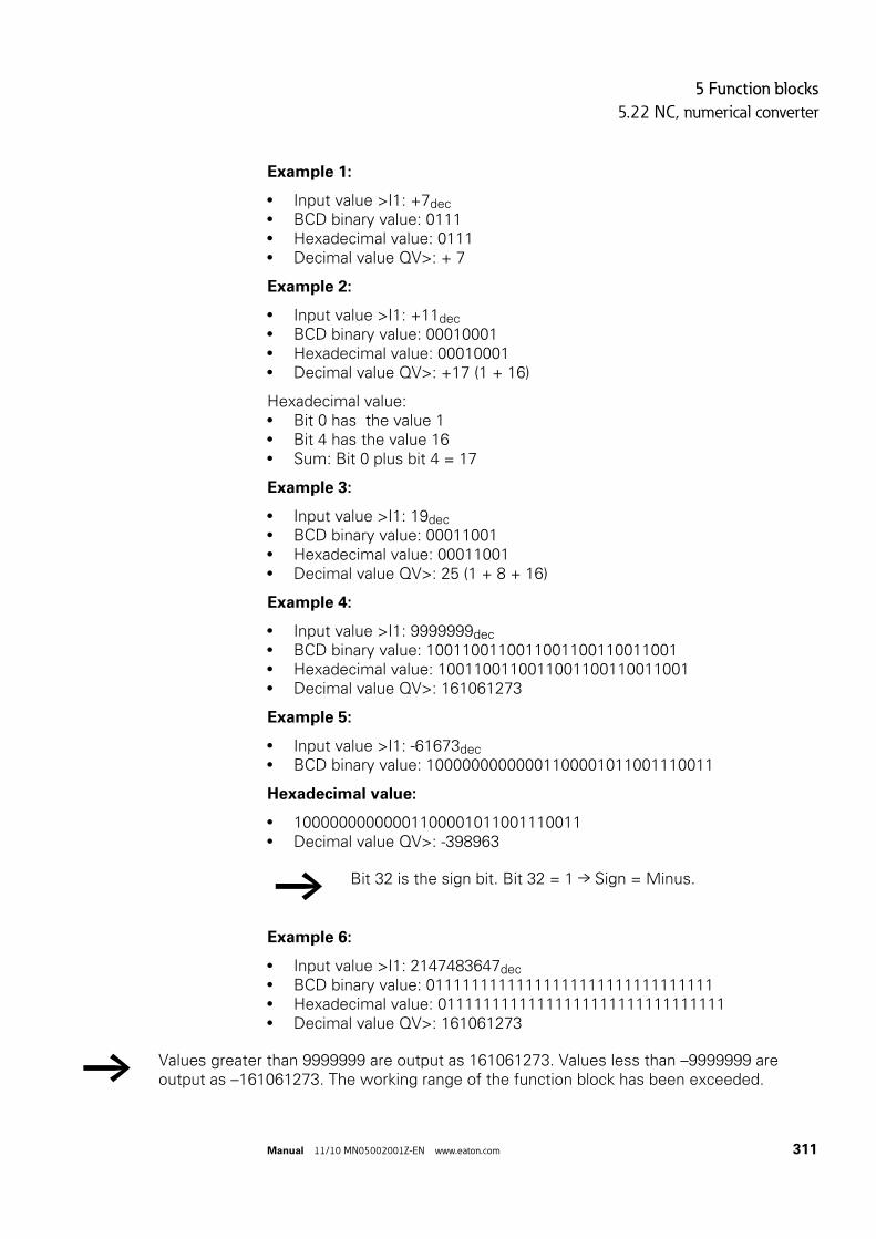
5 Function blocks
5.22 NC, numerical converter
Manual 11/10 MN05002001Z-EN www.eaton.com 311
Example 1:
• Input value >I1: +7dec
• BCD binary value: 0111• Hexadecimal value: 0111• Decimal value QV>: + 7
Example 2:
• Input value >I1: +11dec
• BCD binary value: 00010001• Hexadecimal value: 00010001• Decimal value QV>: +17 (1 + 16)
Hexadecimal value:• Bit 0 has the value 1• Bit 4 has the value 16• Sum: Bit 0 plus bit 4 = 17
Example 3:
• Input value >I1: 19dec
• BCD binary value: 00011001• Hexadecimal value: 00011001• Decimal value QV>: 25 (1 + 8 + 16)
Example 4:
• Input value >I1: 9999999dec
• BCD binary value: 1001100110011001100110011001• Hexadecimal value: 1001100110011001100110011001• Decimal value QV>: 161061273
Example 5:
• Input value >I1: -61673dec
• BCD binary value: 10000000000001100001011001110011
Hexadecimal value:
• 10000000000001100001011001110011• Decimal value QV>: -398963
Example 6:
• Input value >I1: 2147483647dec
• BCD binary value: 01111111111111111111111111111111• Hexadecimal value: 01111111111111111111111111111111• Decimal value QV>: 161061273
→ Bit 32 is the sign bit. Bit 32 = 1 → Sign = Minus.
→ Values greater than 9999999 are output as 161061273. Values less than –9999999 are output as –161061273. The working range of the function block has been exceeded.

5 Function blocks
5.23 OT, operating hours counter
312 Manual 11/10 MN05002001Z-EN www.eaton.com
5.23 OT, operating hours counter
The function block is used to record the operating hours of independent events or states. The status of the operating hours counter is also retained when in a de-energized state. As soon as the enable coil of the function block is active, the MFD counts the hours in minutes, although the display only shows hours.
MFD device allows the use of up to 4 hours-run counters.
5.23.1 Function block inputs/outputs
Read the description of the inputs/outputs in the legend points in the following tables.
5.23.2 Wiring of the function blockYou wire the function block in the standard circuit diagram with its coils and contact.
5.23.2.1 CoilsThe enable coil starts the function of the function block.
The reset coil resets the operating hours counter to zero.
5.23.2.2 ContactA closed contact indicates:
Hours-run counter OT01…OT04 (Operating Time)
Boolean inputs/outputs Parameters
Contact Coil Input value Output value
Q1 Setpoint reached ①
EN Activation of the function block ②
RE Resetting a function block ③
I1 Setpoint value ④
QV Actual value ⑤
Parameters Function
② OT..EN Selective activation of the function block
③ OT..RE Reset the counter to zero
Parameters Function
① JC..Q1 Reaching the upper limit setpoint

5 Function blocks
5.23 OT, operating hours counter
Manual 11/10 MN05002001Z-EN www.eaton.com 313
5.23.2.3 Example of an operating hours counter:
Figure 191: Wiring the function block coils
The enable coil of the function block is connected here directly to the device inputs. A marker activates the reset coil.
Figure 192: Wiring of the function block contact
The message of the function block was wired to a device output.
5.23.3 Parametric programming of the function block inputs/outputs
5.23.3.1 ParametersWhen using the function block in the circuit diagram for the first time, use OK to automatically enter the general display of function block parameters, as shown in the figure on the left. Enter the function block settings here. The display contains the following elements:
The parameter set consists of:
Parameter Display
The display of the parameters during operation can be disabled. Further information is provided in → section “4.9.2.1 Parameter assignment from the circuit diagram”, page 191.
This parameter is factory set to +.
Input
The >I1 block input is used to specify the upper setpoint value in hours. When it is reached, the block contact sends a signal.
The function block input >I1 can be assigned the following operands:
• Constant.• Markers MD, MW, MB.
I 10-----------------------------Ä OT03EN M 42-----------------------------Ä OT03RE
OT03Q1---------------------------Ä Q 01
OT03 +
>I1
QV>
OT03 Function block: Operating hours, number 03
+ Parameter display: Call enabled
④ >I1 Upper setpoint in hours: 0 hours - > 100 years
⑤ QV> Actual value of the operating hours counter
Parameters Function
+ Parameters are displayed
- Parameters are not displayed

5 Function blocks
5.23 OT, operating hours counter
314 Manual 11/10 MN05002001Z-EN www.eaton.com
• Analog inputs IA01 to IA04:• IA01: Terminal I7.• IA02: Terminal I8.• IA03: Terminal I11.• IA04: Terminal I12.
• Analog output QA01.• Output …QV> of a different function block.
Output
The output QV> supplies the counted operating hours as an integer value in hours.
You can assign the following operands to output …QV>:
• Analog output QA01• Markers MD, MW, MBMemory requirement
The operating hours counter function block requires 36 bytes of memory plus 4 bytes per constant at the function block input.
Cycle time
5.23.4 Function of the function blockIf the enable coil OT…EN is triggered to the 1 state, the counter adds the value 1 to its actual value every minute (basic clock rate: 1 minute).
If the actual value on QV> reaches the setpoint value of >I1, the contact OT…Q1 switches for as long as the actual value is greater than or equal to the setpoint value.
The actual value is retained in the unit until the reset coil OT…RE is actuated. The actual value is then set to zero.
5.23.4.1 AccuracyThe operating hours counter is accurate to the nearest minute. If the enable coil signal is terminated within a minute, the value for seconds is lost.
The value range of the operating hours counter is between 0 hours and 100 years.
mode Cycle time [μs]
- 25
→ The following operations do not clear the actual value of the hours-run counter: Operating mode change RUN, STOP, voltage ON, OFF, Delete program, Change program, Load new program.

5 Function blocks
5.24 PT - Put value to the NET
Manual 11/10 MN05002001Z-EN www.eaton.com 315
5.24 PT - Put value to the NET
The PUT function block PT.. enables you to transfer a 32-bit operand to the NET. The operand value is transferred and automatically read by the corresponding GET function block GT of another NET station.
MFD device allows the use of up to 32 PUT function blocks.
5.24.1 Function block inputs/outputs
Read the description of the inputs/outputs in the legend points in the following tables.
5.24.2 Wiring of the function blockYou wire the function block in the circuit diagram with its trigger coil and its contacts.
5.24.2.1 CoilOn activation the function block temporarily stores the input value and transfers it to the NET.
Function block PUT PT01…PT32 (PuT)
Boolean inputs/outputs Parameters
Contact Coil Input value Output value
T_ Trigger confirmation ①
AC Buffering and transfer to NET ②
E1 Transmission error ③
T_ Trigger Signal ④
I1 The setpoint that is to be transferred to the NET network ⑤
Parameters Function
④ PT..T_ Trigger coil, on a rising edge the function block temporarily stores the input value and transfers it to the NET

5 Function blocks
5.24 PT - Put value to the NET
316 Manual 11/10 MN05002001Z-EN www.eaton.com
5.24.2.2 ContactsA closed contact indicates:
1) These outputs are available from device version 05.
5.24.2.3 Example of a PUT function block:
Figure 193: Wiring the trigger coil
The trigger coil is connected to a device input.
Figure 194: Wiring the function block contacts
The contacts transfer the function block information to markers.
5.24.3 Parametric programming of the function block inputs/outputs
5.24.3.1 ParametersWhen using the function block in the circuit diagram for the first time, use OK to automatically enter the general display of function block parameters, as shown in the figure on the left. Enter the function block settings here. The display contains the following elements:
The parameter set consists of:
Parameters Function
① PT..Q1 The trigger coil is active
② PT..AC The temporary storage and subsequent transfer of the input value to the NET. 1).
③ PT..E1 A transfer error. 1)
I 05--------------------------Ä PT07T_
PT07Q1---------------------------Ä M 11 PT07AC---------------------------Ä M 22 PT07E1---------------------------Ä M 33
PT07 -
>I1
PT07 Function block: PUT, number 07
- Parameter display: Call not enabled
⑤ >I1 Input value that is to be put onto the NET: -2147483648 - 2147483647

5 Function blocks
5.24 PT - Put value to the NET
Manual 11/10 MN05002001Z-EN www.eaton.com 317
Parameter Display
The display of the parameters during operation can be disabled. Additional information → section “4.9.2.1 Parameter assignment from the circuit diagram”, page 191.
This parameter is factory set to +.
Input
>I1: When the function block is triggered, the value present at function block input >I1 is temporarily stored and then transferred to the NET. The function block input can be assigned the following operands:
• Constant.• Markers MD, MW, MB.• Analog inputs IA01 to IA04:
• IA01: Terminal I7.• IA02: Terminal I8.• IA03: Terminal I11.• IA04: Terminal I12.
• Analog output QA01.• Output …QV> of a different function block.
Memory requirement
The PUT function block requires 36 bytes of memory plus 4 bytes per constant at the function block input.
Cycle time
5.24.3.2 PUT diagnosticsThe PUT function block only functions if the NET is running properly (→ section “9.3 Diagnostics”, page 479).
Parameters Function
+ Parameters are displayed
- Parameters are not displayed
mode Cycle time [μs]
- 25

5 Function blocks
5.24 PT - Put value to the NET
318 Manual 11/10 MN05002001Z-EN www.eaton.com
5.24.4 Function of the function blockWhen the trigger coil PT..T_ picks up, the contact PT..Q1 and stays closed for as long as the trigger coil remains activated.
The pickup triggers the buffering of the input value present at input >I1. The function block then transfers this value to the NET. During this time, the function block contact PT..Q1 closes.
If the temporarily stored value is not sent, the contact PT..E1 closes and therefore indicates a transfer error. It stays closed until the trigger coil PT..T_ picks up to issue a new send job.
The signal diagram shows the relationship of the send job and its triggering by the trigger coil:
Figure 195: Signal diagram of PUT function block
1: Trigger coil
2: trigger coil contact feedback
3: Send
1
2
3

5 Function blocks
5.25 PW, pulse width modulation
Manual 11/10 MN05002001Z-EN www.eaton.com 319
5.25 PW, pulse width modulation
The PW function block modulates the pulse duty factor of a square wave signal, and thus changes the mark to space ratio and pulse duration. The period duration of the signal is unchanged.
The function block is primarily used for outputting the manipulated variable of a PID controller. The maximum frequency is 200 Hz. This corresponds to a period duration of 5 ms. The maximum period duration is 65.5 s.
2 function blocks are provided. Each function block is assigned an output for pulse width modulation: PW01 -> Q01 / PW02 -> Q02. The Q01/Q02 outputs used must not be processed elsewhere in the circuit diagram.
5.25.1 Function block inputs/outputs
Read the description of the inputs/outputs in the legend points in the following tables.
5.25.2 Wiring of the function blockYou wire the function block in the circuit diagram with its enable coil and its signal contact.
→ When using the pulse width modulation function block with a minimum on time of less than 1 s only use devices with transistor outputs.
→ A status change at Q01 or Q02 generated by the circuit diagram is suppressed in favor of the higher prioritized status change by the function block.
Pulse width modulation PW01…PW02 (Pulse Width modulation)
Boolean inputs/outputs Parameters
Contact Coil Input value Output value
E1 Error output ①
EN Activation the function block ②
SV Manipulated variable ③
PD Period duration [ms] ④
ME Minimum On duration [ms] ⑤
→ Avoid unforeseeable switch states. Only use each coil of a relay once in the circuit diagram.

5 Function blocks
5.25 PW, pulse width modulation
320 Manual 11/10 MN05002001Z-EN www.eaton.com
5.25.2.1 CoilThe coil PW..EN is used to activate the function block in the circuit diagram.
5.25.2.2 ContactA closed contact indicates:
5.25.2.3 Example:
Figure 196: Wiring the enable coil
The enable coil PW..EN is directly assigned to marker M25.
Figure 197: Wiring of the signal contact
The function block contact PW..E1 signals to marker M12.
5.25.3 Parametric programming of the function block inputs/outputs
5.25.3.1 ParametersWhen using the function block in the circuit diagram for the first time, use OK to automatically enter the general display of function block parameters, as shown in the figure on the left. Enter the function block settings here. The display contains the following elements:
The parameter set consists of:
Parameters Function
② PW..EN Selective activation of the function block
Parameters Function
① PW..E1 Fault message: minimum on time or minimum off time exceeded
M 25---------------------------Ä PW01EN
PW01E1-------------------------Ä M 12
PW01 +
>SV
>PD
>ME
PW01 Function block; Data multiplexer, number 01
+ Parameter display: Call enabled
③ >SV Manipulated variable: 0 - 4095
④ >PD Period duration: 0 - 65535 ms
⑤ >ME Minimum on duration, minimum off duration: 0 - 65535 ms

5 Function blocks
5.25 PW, pulse width modulation
Manual 11/10 MN05002001Z-EN www.eaton.com 321
Parameter Display
The display of the parameters during operation can be disabled. Additional information → section “4.9.2.1 Parameter assignment from the circuit diagram”, page 191.
This parameter is factory set to +.
Inputs
>SV: Assign the manipulated variable to function block input >SV.
>PD: Input >PD is used to define the period duration.
>ME: You set the minimum on duration, minimum off duration at input >ME.
You can assign the following operands to function block inputs >SV and >PD to >ME:
• Constant• Markers MD, MW, MB• Analog inputs IA01 to IA04:
• IA01: Terminal I7• IA02: Terminal I8• IA03: Terminal I11• IA04: Terminal I12
• Analog output QA01• Output …QV> of a different function block
Memory requirement
The pulse width modulation function block requires 48 bytes of memory plus 4 bytes per constant at the function block input.
Cycle time
Parameters Function
+ Parameters are displayed
- Parameters are not displayed
→ The minimum setting for the period duration is 5, i.e. 0.005 s (5 ms)
mode Cycle time [μs]
- 243

5 Function blocks
5.25 PW, pulse width modulation
322 Manual 11/10 MN05002001Z-EN www.eaton.com
5.25.4 Function of the function block
The manipulated variable at function block input >SV is converted to a pulse string with a constant period duration. The pulse width is proportional to the manipulated variable >SV. The period duration and the minimum on duration can be selected as required within the specified limits.
The function block causes a direct output of the pulse to the corresponding device output (Q1 and Q2). The output image of the circuit diagram is always updated.
→ The pulse width modulation function block must be enabled so that it can work. Coil PW…EN must be active. If coil PW…EN is not active, the entire function block is deactivated and reset. The output value is set to zero.
→ The following applies if the output of a pulse width modulator is used as a coil in the circuit diagram:The state of the output is not refreshed from the circuit diagram.
→ The following applies to the minimum on duration:• The minimum on duration is equal to the minimum off
duration.• The minimum on duration must not exceed 10 % of the
period duration. The ratio of period duration/minimum on duration (P/M) determines which percentage of the manipulated variable has no effect. The minimum on duration must be set as low as possible so that the P/M ratio is as high as possible. If the minimum on duration must not be too low, due to the output relay, the period duration must be increased accordingly.
• The minimum on duration is 1 ms.• If the actual value of the pulse length is less than the
minimum on duration, the minimum on duration has the effect of the pulse time. The status of the PW..E1 contact must be observed.
• If the off duration of the pulse is less than the minimum off duration, outputs Q1 and Q2 are continuously in operation. The status of the PW..E1 contact must be observed.

5 Function blocks
5.26 SC, set date/time
Manual 11/10 MN05002001Z-EN www.eaton.com 323
5.26 SC, set date/time
This function block allows you to selectively place the date and time onto the network. All other stations accept the date and time of the sending station.
MFD device allows the use of one "set date/time function block".
5.26.1 Function block inputs/outputs
Read the description of the inputs/outputs in the legend points in the following tables.
5.26.2 Wiring of the function blockYou wire the function block in the circuit diagram with its trigger coil and its contact.
5.26.2.1 Coil
5.26.2.2 ContactA closed contact indicates:
5.26.2.3 Example of a set date/time function block:
Figure 198: Wiring the trigger coil
The trigger coil is connected to a device input.
Set date/time SC01 (Set Clock)
Boolean inputs/outputs Parameters
Contact Coil Input value Output value
Q1 Trigger confirmation ①
T_ Trigger Signal ②
Parameters Function
② SC01T_ Trigger coil, on rising edge the function block transfers date and time of the sending station to the NET
Parameters Function
① SC01Q1 The trigger coil is active
I 05--------------------------Ä SC01T_

5 Function blocks
5.26 SC, set date/time
324 Manual 11/10 MN05002001Z-EN www.eaton.com
Figure 199: Wiring of the function block contact
The contact is assigned to a marker.
5.26.3 Parametric programming of the function block inputs/outputsParameters
This function block is a triggerable system service. It therefore does not have any parameters.
Memory requirement
The SC function block requires 20 bytes of memory.
Cycle time
5.26.3.1 SC diagnosticsThe SC function block only functions if the easyNet network is running properly (→ section “9.3 Diagnostics”, page 479).
5.26.4 Function of the function blockIf the trigger coil of the function block is activated, the current date, the day of the week and time from the sending station is automatically put onto the easyNet network. The sending stations executes this operation as soon as a new minute starts on the device real-time clock. The other stations accept this value.
Example
The trigger pulse is set at 03:32:21 (hh:mm:ss). The other stations are synchronized at 03:33:00. The time is accepted by all stations. This process can be repeated as often as desired.
5.26.4.1 Accuracy of time synchronizationThe maximum time deviation between the functional stations is 5 s.
SC01Q1---------------------------Ä M 11
mode Cycle time [μs]
- 23

5 Function blocks
5.27 SR, shift register
Manual 11/10 MN05002001Z-EN www.eaton.com 325
5.27 SR, shift register
The shift register function block enables you to move bits or marker double words one position forwards or backwards with every clock pulse, depending on whether Bit or Double word (DW) operating mode is selected. The shift register has a linear structure. If, for example, a bit is added at one end of the shift register in a bit operation with a clock pulse, a bit will be pushed out at the other end. You can choose between two operating modes:
• Bit (BIT).• Double word (DW).
MFD device allows the use of up to 32 shift registers.
5.27.1 Function block inputs/outputs
Read the description of the inputs/outputs in the legend points in the following tables.
Shift register SR01…SR32 (Shift Register)
Boolean inputs/outputs Parameters
Contact Coil Input value Output value
Q1 …Q8
Bit outputs ①
EN Activation of the function block ②
FP Clock input, shift register forward ③
BP Clock input, shift register backward ④
RE Reset ⑤
FD Bit data input, shift register forward ⑥
BD Bit data input, shift register backward ⑦
I1 Input value for shift direction forwards ⑧
I2 Input value for shift direction backwards ⑨
D1…D8
Register values 1…8 ⑩

5 Function blocks
5.27 SR, shift register
326 Manual 11/10 MN05002001Z-EN www.eaton.com
5.27.2 Wiring of the function blockIn BIT operating mode you integrate the shift register function block in the standard circuit diagram with its coils and contacts.
5.27.2.1 CoilsThe coil SR..EN is used to activate the function block in the circuit diagram.
The forwards pulse input coil SR..FP triggers the following function when it is activated, depending on the operating mode:
The remaining content of the register is then moved forwards.
The backwards pulse input coil SR..BP triggers the following function when it is activated, depending on the operating mode:
The remaining content of the register is then moved backwards.
The reset coil SR..RE causes the following in both directions:
Parameters Function
② SR..EN Selective activation of the function block
Parameters Function
③ SR..FP Pulse input forwardsBIT mode: Transfer of the data bit at the input coil SR..FD into the register SR..Q1.DW operating mode: Transfer of the value SR..I1 to the register SR..D1.
Parameters Function
④ SR..BP Pulse input backwardsBIT mode: Transfer of the data bit at the input coil SR..BD into the register SR..Q8.DW operating mode: Transfer of the value SR..I2 to the register SR..D8.
Parameters Function
⑤ SR..RE Reset of the register
Parameters Function
⑥ SR..FD Data bit forwards
Parameters Function
⑦ SR..BD data bit backwards

5 Function blocks
5.27 SR, shift register
Manual 11/10 MN05002001Z-EN www.eaton.com 327
5.27.2.2 ContactsThe function block in BIT mode has 8 contacts SR..Q1 to SR..Q8 for the circuit diagram.
5.27.2.3 Examples
Figure 200: BIT operating mode, wiring the function block coils
The function block coils are switched by markers.
Figure 201: BIT operating mode, wiring the function block contacts
The contacts of the function block are connected with markers.
In DW operating mode you only integrate the coils in the circuit diagram:
Figure 202: DW operating mode, wiring the function block contacts
You assign parameters to inputs and outputs in the function block diagram.
Coil Function
① SR..Q1 - SR..Q8
Output of the bit register fields 1 - 8
M 10--------------------------Ä SR01EN M 11--------------------------Ä SR01FD M 12--------------------------Ä SR01FP M 13--------------------------Ä SR01BD M 14--------------------------Ä SR01BP M 15--------------------------Ä SR01RE
SR01Q1------------------------Ä M1 SR01Q2------------------------Ä M2 SR01Q3------------------------Ä M3 SR01Q4------------------------Ä M4 SR01Q5------------------------Ä M5 SR01Q6------------------------Ä M6 SR01Q7------------------------Ä M7 SR01Q8------------------------Ä M8
M 05--------------------------Ä SR01EN M 06--------------------------Ä SR01FP M 07--------------------------Ä SR01BP M 08--------------------------Ä SR01RE

5 Function blocks
5.27 SR, shift register
328 Manual 11/10 MN05002001Z-EN www.eaton.com
5.27.3 Parametric programming of the function block inputs/outputs
5.27.3.1 ParametersWhen using the function block in the circuit diagram for the first time, use OK to automatically enter the general display of function block parameters, as shown in the figure on the left. Enter the function block settings here.
The parameter display is the same for both operating modes and only the parameter for data format is different.
Operating Mode
With this parameter you define whether you wish to run the shift register as a bit register or in double word format.
The factory setting of this parameter is BIT.
• BIT operating modeThe function block must be included in the program. Once selected, the parameter block appears, as shown on the left. In this operating mode, the data bit is transferred to the SR..FS input coil to be shifted forward and to SR..BD to be shifted backward.
Parameters Function, parameterization in the function block
BIT Bit operation
DW Double word operation
SR01 BIT +
>I1
>I2
D1>
D2>
D3>
D4>
D5>
D6>
D7>
D8>
→ The displayed inputs/outputs of the function block I1, I2 and D1-D8 have no function in BIT mode! If they are assigned operands, these will have no effect. The wiring of the SR function block (BIT) is carried out in the circuit diagram.

5 Function blocks
5.27 SR, shift register
Manual 11/10 MN05002001Z-EN www.eaton.com 329
• DW operating mode
The parameter set consists of:
Parameter Display
The display of the parameters during operation can be disabled. Further information on this is provided → Section "4.9.2.1 Parameter assignment from the circuit diagram“ on page 191.
This parameter is factory set to +.
Inputs
>I1 und >I2: In DW operating mode you assign function block inputs >I1 and >I2 with the values that are to be read into the shift register. You can assign the following operands to function block inputs:
• Constant.• Markers MD, MW, MB.• Analog inputs IA01 to IA04:
• IA01: Terminal I7.• IA02: Terminal I8.• IA03: Terminal I11.• IA04: Terminal I12.
• Analog output QA01.• Output …QV> of a different function block.
SR01 DW +
>I1
>I2
D1>
D2>
D3>
D4>
D5>
D6>
D7>
D8>
SR01 Function block: SR shift register, number 01
DW Operating mode: Double word marker operation
+ Appears in the parameter display
⑧ >I1 Input value forwards:-2147483648 - 2147483647
⑨ >I2 Input value backwards:-2147483648 - 2147483647
⑩ D1> Register value 1 of the shift register, Value range of all registers: -2147483648 - +2147483647
D2> Register value 2
D3> Register value 3
D4> Register value 4
D5> Register value 5
D6> Register value 6
D7> Register value 7
D8> Register value 8
Parameters Function
+ Parameters are displayed
- Parameters are not displayed

5 Function blocks
5.27 SR, shift register
330 Manual 11/10 MN05002001Z-EN www.eaton.com
Outputs
D1> to D8>: Likewise, only in DW operating mode do the function block outputs D1> to D8> output register values 1 to 8. The outputs can have the following operands:
• Analog output QA01.• Markers MD, MW, MB.
Memory requirement
The SR function block requires 96 bytes of memory plus 4 bytes per constant at the function block input.
5.27.4 Function of the function block
The shift register has a linear structure. This means that a clock pulse initiates the following actions:
• A new value/data bit is transferred to the register and the other data is moved one place further in the register.
• The value/data bit at the other end of the register is pushed out.• Both shift directions, forwards and backwards, are possible.
The function block has two operating modes for different data formats:
• BIT for a bit data format• DW for a double word data format.
In BIT operating mode, the function block uses
• Input coils: SR..FD and SR..BD.• Register field contacts: SR..Q1 to SR..Q8.
In DW operating mode the function block processes inputs and outputs in double word format:
• Inputs SR..I1 and SR..I2• Outputs: SR..D1 to SR..D8.
SR..FD and SR..I1 are for data that the function block transfers to register Q1 or D1 in a forwards direction when SR..FP is activated.
The following two figures illustrate the process for forward shift operations in BIT and DW modes.
→ The shift register function block must be enabled so that it can work, i.e. the coil SR..EN must be active. If this is not active, the entire function block is deactivated.

5 Function blocks
5.27 SR, shift register
Manual 11/10 MN05002001Z-EN www.eaton.com 331
Figure 203: Shift register SR..: Forwards operation in BIT operating mode
a Initial situation
– SR..EN is not activated, the function block is not active.– SR..Q7 contains a data bit 1, a 0 is contained in the other register fields.
b Transfer of a data bit:
– SR..EN is activated, the function block is active.– SR..FD has data bit 1.– With the forwards pulse from SR..FP the register field SR..Q1 shifts the content of all register fields
one place forwards and accepts the 1 from SR..FD.c Transfer of a data bit:
– SR..EN is activated, the function block is active.– SR..FD has data bit 0.– with the forwards pulse from SR..FP the register field SR..Q1 shifts the content of all register fields
one place forwards and accepts the 0 from SR..FD.d Reset of the register:
– SR..EN is activated, the function block is active.– Activating SR..RE clears the content of the register.
1
Q1Q2Q3Q4Q5Q6Q7Q8
Q1Q2Q3Q4Q5Q6Q7Q8
Q1Q2Q3Q4Q5Q6Q7Q8
00000000
01000000
10000001
00000010
a b c d
SR...BITShift Register
EN
SR...BITShift Register
ENRE
FPFD
RE
FPFD Q1
Q2Q3Q4Q5Q6Q7Q8
SR...BITShift Register
ENRE
FPFD
SR...BITShift Register
ENRE
FPFD1
1
1
1 11
0

5 Function blocks
5.27 SR, shift register
332 Manual 11/10 MN05002001Z-EN www.eaton.com
Figure 204: Shift register SR..: Forwards operation in DW mode
a Initial situation:
– SR..EN is not activated, the function block is not active.– SR..D7 contains the value 8, a 0 is contained in the other register fields.
b Transfer of value:
– SR..EN is activated, the function block is active.– SR..I1 has the value 10.– With the forwards pulse from SR..FP the register field SR..D1 shifts the content of all register fields
one place forwards and accepts the 10 from SR..I1.c Transfer of value:
– SR..EN is activated, the function block is active.– SR..I1 has the value 52.– with the forwards pulse from SR..FP the register field SR..D1 shifts the content of all register fields
one place forwards and accepts the 52 from SR..I1.d Reset of the register:
– SR..EN is activated, the function block is active.– Activating SR..RE clears the content of the register.
D1:D2:D3:D4:D5:D6:D7:D8:
8
00000000
5210000000
100000008
00000080
a b c d
SR...DWShift Register
EN
SR...DWShift Register
ENRE
FP>I1
RE
FP>I1
SR...DWShift Register
ENRE
FP>I1
SR...DWShift Register
ENRE
FP>I110
1
52
1 11
0
D1:D2:D3:D4:D5:D6:D7:D8:
D1:D2:D3:D4:D5:D6:D7:D8:
D1:D2:D3:D4:D5:D6:D7:D8:

5 Function blocks
5.27 SR, shift register
Manual 11/10 MN05002001Z-EN www.eaton.com 333
SR..BD and SR..I2 are for data that the function block transfers to register Q8 or D8 in a backwards direction when SR..BP is activated, → Figure 205 and 206.
Figure 205: Shift register SR..: Backwards operation in BIT operating mode
a Initial situation:
– SR..EN is not activated, the function block is not active.– SR..Q7 contains a data bit 1, a 0 is contained in the other register fields.
b Transfer of a data bit:
– SR..EN is activated, the function block is active.– SR..BD has data bit 1.– With the backwards pulse from SR..BP the register field SR..Q8 shifts the content of all register fields
one place back and accepts the 1 from SR..BD.c Transfer of a data bit:
– SR..EN is activated, the function block is active.– SR..BD has data bit 0.– With the backwards pulse from SR..BP the register field SR..Q8 shifts the content of all register fields
one place back and accepts the 0 from SR..BD.d Reset of the register:
– SR..EN is activated, the function block is active.– Activating SR..RE clears the content of the register.
Q1Q2Q3Q4Q5Q6Q7Q8
Q1Q2Q3Q4Q5Q6Q7Q8
Q1Q2Q3Q4Q5Q6Q7Q8
00000000
00001011
00000101
00000010
a b c d
SR...BITShift Register
EN
SR...BITShift Register
ENRE
BPBD
RE
BPBD
Q1Q2Q3Q4Q5Q6Q7Q8
SR...BITShift Register
ENRE
BPBD
SR...BITShift Register
ENRE
BPBD1
1
1
1 11
0 0

5 Function blocks
5.27 SR, shift register
334 Manual 11/10 MN05002001Z-EN www.eaton.com
Figure 206: Shift register SR..: Backwards operation in DW operating mode
a Initial situation:
– SR..EN is not activated, the function block is not active.– SR..D2 contains the value 8, a 0 is contained in the other register fields.
b Transfer of value:
– SR..EN is activated, the function block is active.– SR..I2 has the value 10.– With the backwards pulse from SR..BP the register field SR..D8 shifts the content of all register fields
one place back and accepts the 10 from SR..I2.c Transfer of value:
– SR..EN is activated, the function block is active.– SR..I2 has the value 52.– With the backwards pulse from SR..BP the register field SR..D8 shifts the content of all register fields
one place back and accepts the 52 from SR..I2.d Reset of the register:
– SR..EN is activated, the function block is active.– Activating SR..RE clears the content of the register.
00000000
D1:D2:D3:D4:D5:D6:D7:D8:
000000
1052
D1:D2:D3:D4:D5:D6:D7:D8:
8000000
10
D1:D2:D3:D4:D5:D6:D7:D8:
08000000
a b c d
SR...DWShift Register
EN
SR...DWShift Register
ENRE
BP>I2
RE
BP>I2
D1:D2:D3:D4:D5:D6:D7:D8:
SR...DWShift Register
ENRE
BP>I2
SR...DWShift Register
ENRE
BP>I210
1
52
1 11
0 8

5 Function blocks
5.27 SR, shift register
Manual 11/10 MN05002001Z-EN www.eaton.com 335
5.27.4.1 Example 1A sequence of operating steps is controlled using a bit shift register.
The individual operating steps are permanently assigned to a register field. A step is initiated when its register contact is switched. As soon as it is completed, SR..FP is activated and the subsequent register contact starts the next step. The first operating step is carried out if the 1 at the register input is transferred to the register when SR.FP is activated and is indicated at SR..Q1.
The figure on the left shows the parameter display and the parameter set for the function block SR12. Once shift register number 12 has been defined, you set here only BIT operating mode for the bit format.
The coils are programmed in the circuit diagram of MFD:
Figure 207: MFD circuit diagram for example 1
• The enable coil SR12EN is permanently active, the function block is not switched off.
• Marker M09 transfers the 1 to SR12FD for the first step.• Marker M10 switches the forwards pulse input coil SR12FP.
5.27.4.2 Example 2Different workpieces are moved along a production line with several machining stations. An operator determines the work required for the individual workpieces, creates a production code for it and writes it into a shift register.
The workpieces reach the machining stations in this order. When the workpiece is changed, the stations read the required production steps from their permanently assigned register field.
When workpiece 1 moves to the first station, the forwards pulse input coil SR01FP and the shift register SR01 receive production code 1 at input SR01I1 from the double word marker MD11.
Production code 1 is now at the register field SR01D1 for the first machining station which reads it from double word marker MD01.
The finished workpiece is then transferred to station 2. The shift register accepts the production code 2 for the next workpiece. Production code 1 moves one place forwards, as does the remaining register content. It now stands at register output SR01D2. It reaches machining station 2 via double word marker MD02.
The process is repeated for each further workpiece and for each further machining station until the finished workpieces leave the line.
SR12 BIT +
>I1
>I2
D1>
------------------------------Ä SR12EN M 09--------------------------Ä SR12FD M 10--------------------------Ä SR12FP

5 Function blocks
5.27 SR, shift register
336 Manual 11/10 MN05002001Z-EN www.eaton.com
The coils are programmed in the circuit diagram of MFD:
Figure 208: MFD circuit diagram for example 2
• The enable coil SR01EN is permanently active, the function block is not switched off.
• Marker M09 switches the forwards pulse input coil SR01FP.
The figure on the left shows the parameter display and the parameter set. After defining shift register number 01, you set here the following parameters:
• the DW operating mode for the double word marker format.• the double word markers for receiving the production code.
------------------------------Ä SR01EN M 09--------------------------Ä SR01FP
SR01 DW +
>I1 MD11
>I2
D1> MD01
D2> MD02
D3> MD03
D4>
D5>
D6>
D7>
D8>

5 Function blocks
5.28 ST, Set cycle time
Manual 11/10 MN05002001Z-EN www.eaton.com 337
5.28 ST, Set cycle time
The Set cycle time function block is used as an additional function block for the PID controller and the counter function blocks. It provides a fixed cycle time for processing the circuit diagram and the function blocks. When used with a PID controller it improves the control response. It can also be used to suppress the sporadic lengthening of the cycle time when changing screens in the MFD. One function block is provided.
5.28.1 Function block inputs/outputs
Read the description of the inputs/outputs in the legend points in the following tables.
5.28.2 Wiring of the function blockYou wire the function block in the circuit diagram with an enable coil.
5.28.2.1 Coil
5.28.2.2 Example of a function block for setting the set cycle time:
Figure 209: Wiring the enable coil
5.28.3 Parametric programming of the function block inputs/outputs
5.28.3.1 ParametersWhen using the function block in the circuit diagram for the first time, use OK to automatically enter the general display of function block parameters, as shown in the figure on the left. Enter the function block settings here. The display contains the following elements:
Cycle time ST1 (Set Time)
Boolean inputs/outputs Parameters
Contact Coil Input value Output value
EN Activation of the function block
I1 Required Cycle Time in ms ②
Parameters Function
① ST01EN Selective activation of the function block
I 05--------------------------Ä ST01EN
ST01 +
>I1

5 Function blocks
5.28 ST, Set cycle time
338 Manual 11/10 MN05002001Z-EN www.eaton.com
The parameter set consists of:
Parameter Display
The display of the parameters during operation can be disabled. Additional information → section “4.9.2.1 Parameter assignment from the circuit diagram”, page 191.
This parameter is factory set to +.
Input
>I1: The set cycle time is entered at function block input >I1.
The function block input >I1 can be assigned the following operands:
• Constant.• Markers MD, MW, MB.• Analog inputs IA01 to IA04:
• IA01: Terminal I7.• IA02: Terminal I8.• IA03: Terminal I11.• IA04: Terminal I12.
• Analog output QA01.• Output …QV> of a different function block.
Memory requirement
The Set cycle time function block requires 24 bytes of memory plus 4 bytes per constant at the function block input.
ST01 Function block: Set cycle time, number 11
+ Parameter display: Call enabled
② >I1 Set cycle time: 0 - 1000 ms
Parameters Function
+ Parameters are displayed
- Parameters are not displayed

5 Function blocks
5.28 ST, Set cycle time
Manual 11/10 MN05002001Z-EN www.eaton.com 339
5.28.4 Function of the function blockThe function block is used to define a fixed cycle time.
Cycle time less than set cycle time:
If the maximum cycle time present is less than the set cycle time, the set cycle time is constant.
Actual cycle time greater than set cycle time:
If the cycle time present is greater than the set cycle time, the set cycle time has no effect.
→ The function block must be enabled so that it can work. Coil ST01EN is active. If coil ST01EN is not active, the entire function block is deactivated and reset.
CAUTION
The shorter the cycle time, the faster the control and regulation process.Set as small a value for the set cycle time as possible. The processing of the function blocks, reading of the inputs and writing of outputs is only carried out once every cycle.Exception: All function blocks that are processed independently of the cycle time.

5 Function blocks
5.29 T, timing relay
340 Manual 11/10 MN05002001Z-EN www.eaton.com
5.29 T, timing relay
With this timing relay you change the switch time and the on and off time of a switch contact. The adjustable delay times are between 50 ms and 99 h 59 min.
An MFD device allows the use of up to 32 timing relays.
5.29.1 Function block inputs/outputs
Read the description of the inputs/outputs in the legend points in the following tables.
5.29.2 Wiring of the function blockYou wire the function block in the circuit diagram with its coils and contact.
5.29.2.1 CoilsThe trigger coil starts the timing relay in the circuit diagram, the Reset coil resets the run down of the timing relay to zero and the Stop coil interrupts the run down.
→ page 358 on „Example with timing relay and counter function block“ provides information on the timing relay and counter function block.
Timing Relay T01…T32 (Timer)
Boolean inputs/outputs Parameters
Contact Coil Input value Output value
Q1 Switching contact ①
EN Activation the function block ②
RE Set actual value (QV) to 0 ③
ST Stop of the timing relay ④
I1 Time setpoint 1 ⑤
I2 Time setpoint 2 ⑥
QV Elapsed Time ⑦
Parameters Function
② T ..EN Triggering (start) of the timing relay
③ T ..RE Reset of the timing relay
④ T ..ST Stop of the timing relay

5 Function blocks
5.29 T, timing relay
Manual 11/10 MN05002001Z-EN www.eaton.com 341
5.29.2.2 ContactA closed contact indicates:
5.29.2.3 Timing relay example:
Figure 210: Wiring the function block coils
The trigger coil of the function block is connected here directly to the device inputs. A marker activates the reset coil, another marker activates the stop coil.
Figure 211: Wiring of the function block contact
The function block indication signal is assigned directly to a device output.
5.29.3 Parametric programming of the function block inputs/outputs
5.29.3.1 ParametersWhen using the function block in the circuit diagram for the first time, use OK to automatically enter the general display of function block parameters, as shown in the figure on the left. Enter the function block settings here. The display contains the following elements:
The parameter set consists of:
Parameters Function
① T ..Q1 Time function active
I 10-----------------------------Ä T 02EN M 42-----------------------------Ä T 02RE M 43-----------------------------Ä T 02ST
T 02Q1---------------------------Ä Q 01
T 02 X M:S +
>I1
>I2
QV>
T 02 Function block: Timing relay, number 02
X Operating mode: On-delayed
m:s Time range: Minute: Seconds
+ Parameter display: Call enabled
⑤ >I1 Setpoint 1
⑥ >I2 Setpoint 2 (for relay functions with 2 times)
⑦ QV> Display: Elapsed time

5 Function blocks
5.29 T, timing relay
342 Manual 11/10 MN05002001Z-EN www.eaton.com
Operating Mode
This parameter defines the switch function of the timing relay:
Time Range
The function block parameter determines in which time range and at which resolution the relay operates.
Parameter Display
The display of the parameters during operation can be disabled. Additional information → section “4.9.2.1 Parameter assignment from the circuit diagram”, page 191.
This parameter is factory set to +.
Parameters Switch function
X On-delayed switching
?X On-delayed switching with random time range
â Off-delayed switching
?â Off-delayed switching with random time range
Xâ On- and off-delayed
# Off-delayed with random time range, setpoint retriggerable
?# Off-delayed with random time range, retriggerable
?Xâ On- and off-delayed switching with random time, 2 time setpoints
ü Single pulse switching
Ü Flashing, synchronous, 2 setpoints
Ü Flashing, asynchronous, 2 setpoints
Parameters Time range and setpoint Resolution
S 000.00 Seconds; 0.05 to 999.995 s for constants and variable values 5 ms
M:S 00:00 Minutes:Seconds; 00:00 to 99:59 only for constants and variable values 1 s
H:M 00:00 Hours:Minutes; 00:00 to 99:59 only for constants and variable values 1 min.
→ Minimum time setting: 0.005 s (5 ms) If a setpoint value is less than the MFD cycle time, the elapsed time will only be recognized in the next cycle.
Parameters Function
+ Parameters are displayed
- Parameters are not displayed

5 Function blocks
5.29 T, timing relay
Manual 11/10 MN05002001Z-EN www.eaton.com 343
Inputs
>I1 and >I2: You assign a time value at >I1 and >I2, depending on the switch function of the relay.
You can assign the following operands to function block inputs >I1 and >I2:
• Constant.• Markers MD, MW, MB.• Analog inputs IA01 to IA04:
• IA01: Terminal I7.• IA02: Terminal I8.• IA03: Terminal I11.• IA04: Terminal I12.
• Analog output QA01.• Output …QV> of a different function block.
Output
QV>: Output QV> supplies the currently elapsed time. You can assign the following operands:
• Analog output QA01.• Markers MD, MW, MB.
Memory requirement
The timing relay function block requires 52 bytes of memory plus 4 bytes per function block input configured with an NU constant.
Cycle time
mode Cycle time [μs]
All 60

5 Function blocks
5.29 T, timing relay
344 Manual 11/10 MN05002001Z-EN www.eaton.com
5.29.3.2 RetentionTiming relays can be run with retentive actual values. The number of retentive timing relays can be selected in the SYSTEM → RETENTION menu.
If a timing relay is retentive, the actual value is retained when the operating mode is changed from RUN to STOP and when the power supply is switched off.
If MFD is started in RUN operating mode, the timing relay operates with the retentively saved actual value. The state of the trigger pulse must correspond to the function of the timing relay.
• Status 1 with:• On-delayed.• Single pulse.• Flashing.
• Status 0 with:• Off-delayed.
5.29.4 Function of the function blockThe relay is started via the trigger coil T…EN and can be selectively reset via the reset coil T…RE. The third coil T..ST terminates the run down of the actual time.
Variable time values
If you associate the function block inputs T ..I1 and T ..I2 with operands, you can use variable setpoints. The setpoints are transferred as follows, depending on the time range selected:
• S, value in milliseconds. The last digit is rounded up or down to 0 or 5, maximum value = 999995 ms.
• M:S, value in seconds, maximum value = 5999 s.• H:M, value in minutes, maximum value = 5999 min.
• Examples of time range S:• Operand value 9504 -> Time value is 9.50 s.• Operand value 45507 -> is 45.51 s.
• Examples of time range M:S:• Operand value 5999 -> Time value is 99 h, 59 min.
• Example of time range H:M:• Operand value 5999 -> Time value is 99 h, 59 min.
Different methods are used depending on the operating modes of the function block:
→ The delay times are the same as described for the constants.

5 Function blocks
5.29 T, timing relay
Manual 11/10 MN05002001Z-EN www.eaton.com 345
Timing relay, on-delayed with and without random switching
Random switching:The contact of the timing relay switches randomly within the setpoint value range.
Figure 212: Signal diagram of timing relay, on-delayed (with and without random switching)
1: Trigger coil T…EN
2: Stop coil T…ST
3: Reset coil T…RE
4: Switching contact (N/O contact) T…Q1
ts: setpoint time
• Range A: The time runs down from the set time value.• Range B: The time does not elapse because the trigger coil drops out prematurely.• Range C: The Stop coil stops the time from elapsing.
Figure 213: Signal diagram of timing relay, on-delayed (with and without random switching)
• Range D: The stop coil is inoperative after the time has elapsed.• Range E: The reset coil resets the relay and the contact.• Range F: After the reset coil is activated, the switching contact is switched off and the internal time
counter is reset. The function relay waits for a new trigger pulse.
t1 + t2 = tst
A Bts
1
2
4
3
C
tFD E
ts
1
2
4
3
tsF

5 Function blocks
5.29 T, timing relay
346 Manual 11/10 MN05002001Z-EN www.eaton.com
Timing relay, off-delayed with and without random switching
Random switching, with and without retriggeringThe contact of the timing relay switches randomly within the setpoint value range.
RetriggeringWhen the time is running and the trigger coil is reactivated or deactivated, the actual value is reset to zero. The set time of the timing relay is timed out once more.
Figure 214: Signal diagram of timing relay, off delayed (with/without random switching, with/without retriggering)
1: Trigger coil T…EN
2: Stop coil T…ST
3: Reset coil T…RE
4: Switching contact (N/O contact) T…Q1
ts: Setpoint time.
• Range A: The time elapses after the trigger coil is deactivated.• Range B: The Stop coil stops the time from elapsing.• Range C: The reset coil resets the relay and the contact. After the reset coil drops out, the relay
continues to work normally.• Range D: The Reset coil resets the relay and the contact when the function block is timing out.
Figure 215: Signal diagram of timing relay, off delayed (with/without random switching, with/without retriggering)
• Range E: The trigger coil drops out twice. The set time ts consists of t1 plus t2 (switch function not retriggerable).
• Range F: The trigger coil drops out twice. The actual time t1 is cleared and the set time ts elapses completely (retriggerable switch function).
A Bt1 + t2 = tsts
C
1
2
4
3
tsDt
Et1 + t2 = ts
1
2
4
3
tsF
t1

5 Function blocks
5.29 T, timing relay
Manual 11/10 MN05002001Z-EN www.eaton.com 347
Timing relay, on- and off-delayed with and without random switching
Time value >I1: On delay timeTime value >I2: Off delay time
Random switchingThe contact of the timing relay switches randomly within the setpoint value ranges.
Figure 216: Operational diagrams timing relay, on and off delayed 1
1: Trigger coil T…EN
2: Stop coil T…ST
3: Reset coil T…RE
4: Switching contact (N/O contact) T…Q1
ts1: pick-up time
ts2: reset time
• Range A: The relay processes the two times without any interruption.• Range B: The trigger coil drops out before the on-delay is reached.• Range C: The stop coil stops the timeout of the on-delay.• Range D: The stop coil has no effect in this range.
Figure 217: Operational diagrams timing relay, on and off delayed 2
• Range E: The stop coil stops the timeout of the off-delay.• Range F: The reset coil resets the relay after the on delay has elapsed• Range G: After the reset coil is activated, the internal time counter is reset. The switching contact
remains switched off. The function relay waits for a new trigger pulse.
A B C
1
2
4
3
Dtts1 ts2 ts2 ts1 ts2t1 + t2 = ts1
E Ft1 + t2 = ts2
G
1
2
4
3
tts1 ts1

5 Function blocks
5.29 T, timing relay
348 Manual 11/10 MN05002001Z-EN www.eaton.com
Figure 218: Operational diagrams timing relay, on and off delayed 3
• Range H: The Reset signal interrupts the timing out of the set time.
Timing relay, single pulse
Figure 219: Signal diagram timing relay, single pulse 1
1: Trigger coil T…EN
2: Stop coil T…ST
3: Reset coil T…RE
4: Switching contact (N/O contact) T…Q1
• Range A: The trigger signal is short and is lengthened.• Range B: The trigger signal is longer than the set time.• Range C: The stop coil interrupts the timing out of the set time.
Figure 220: Operational diagram timing relay, pulse shaping 2
• Range D: The reset coil resets the timing relay.• Range E: The reset coil resets the timing relay. The trigger coil is still energized after the reset coil is
disconnected, whilst the delay time runs down.
Ht
1
2
4
3
ts1
A B
t1 + t2 = tsts tsC
1
2
4
3
t
D Et ts
1
2
4
3

5 Function blocks
5.29 T, timing relay
Manual 11/10 MN05002001Z-EN www.eaton.com 349
Timing relay, synchronous and asynchronous flashing
Time value >I1: Mark time Time value >I2: Space time
Synchronous (symmetrical) flashing: >I1 equal >I2Asynchronous flashing: >I1 not equal >I2
Figure 221: Signal diagram: timing relay, synchronous and asynchronous flashing
1: Trigger coil T…EN
2: Stop coil T…ST
3: Reset coil T…RE
4: Switching contact (N/O contact) T…Q1
• Range A: The relay flashes for as long as the trigger coil is activated.• Range B: The stop coil interrupts the timing out of the set time.• Range C: The reset coil resets the relay.
t1 + t2 = ts2ts1 ts1 ts1
ts2 ts2ts1 ts1
ts2ts2A B
1
2
4
3
t ts1ts2
C

5 Function blocks
5.30 TB, table function
350 Manual 11/10 MN05002001Z-EN www.eaton.com
5.30 TB, table function
This function block is available from device version 05.
The table function block enables you to create and read table entries in the form of double words (32-bit). The function block operates on the principle of a stack memory which you can set for reading as either a FIFO or LIFO function (FIFO = First In First Out, LIFO = Last In First Out). A table can contain up to 16 double words.
MFD device allows the use of up to 32 table function blocks.
5.30.1 Function block inputs/outputs
Read the description of the inputs/outputs in the legend points in the following tables.
5.30.2 Wiring of the function blockYou use the table function block in the circuit diagram with its coils and contacts.
Table function TB01…TB32 (Table function)
Boolean inputs/outputs Parameters
Contact Coil Input value Output value
Space units
Table empty ①
TF Table full ②
EN Activation of the function block ③
WP Transfer value at I1 to the table and output at QV ④
RF Oldest value output from table at QV ④
RL Newest value output from table at QV ④
RE Empty table ⑦
I1 Input value ⑧
QV Table output value ⑪
QN Number of existing table entries ⑫

5 Function blocks
5.30 TB, table function
Manual 11/10 MN05002001Z-EN www.eaton.com 351
5.30.2.1 CoilsUse function block coil TB..EN to activate the function block.
With a rising edge at coil TB..WP the input value is read in the table.
The data at function block output QV> depends on which coil was activated:
• TB..WP: the actual input value read.• TB..RF: the first table entry.• TB..RL: the last table entry.The reset coil TB..RE is used to fully delete the table.
5.30.2.2 ContactsA closed contact indicates:
5.30.2.3 Example of a table function block:
Figure 222: Wiring the function block coils
Markers switch the coils of the function block.
Figure 223: Wiring the function block contacts
The function block contact TE (empty) and TF (full) indicate an empty or full table.
Operands are assigned to inputs and outputs in the parameter display.
Parameters Function
③ TB..EN Selective activation of the function block
④ TB..WP Reads the value at input TB..I1, transfers it to the table and outputs at output QV.
⑤ TB..RF Clears the value entered first from the table and outputs it at output QV.
⑥ TB..RL Clears the most recently entered value from the table and outputs it at output QV.
⑦ TB..RE Clears the table content.
Parameters Function
① TB..TE Table is empty
② TB..TF Table is full
M 10--------------------------Ä TB01EN M 11--------------------------Ä TB01WP M 12--------------------------Ä TB01RE M 13--------------------------Ä TB01RF M 13--------------------------Ä TB01RL
TB01TE------------------------Ä M2 TB01TF------------------------Ä M3

5 Function blocks
5.30 TB, table function
352 Manual 11/10 MN05002001Z-EN www.eaton.com
5.30.3 Parametric programming of the function block inputs/outputs
5.30.3.1 ParametersWhen using the function block in the circuit diagram for the first time, use OK to automatically enter the general display of function block parameters, as shown in the figure on the left. This is where you make the function block settings, in this case, the allocation of the inputs and outputs to the operands. The display contains the following elements:
The parameter set consists of:
Parameter Display
The display of the parameters during operation can be disabled. Additional information → section “4.9.2.1 Parameter assignment from the circuit diagram”, page 191.
This parameter is factory set to +.
Input
>I1: The value at input >I1 is read into the table when function block coil TB..WP is activated. The function block input >I1 can be assigned the following operands:
• Constant.• Markers MD, MW, MB.• Analog inputs IA01 to IA04:
• IA01: Terminal I7.• IA02: Terminal I8.• IA03: Terminal I11.• IA04: Terminal I12.
• Analog output QA01.• Output …QV> of a different function block.
TB01 +
>I1
QV>
QN>
TB01 Function block: Table function, number 01
+ Parameter display: Call enabled
⑧ >I1 Table input value:-2147483648 - 2147483647
⑨ QV> Actual, first or last table entry as output value: -2147483648 - 2147483647
⑩ >QN Current number of table entries: 0-16
Parameters Function
+ Parameters are displayed
- Parameters are not displayed

5 Function blocks
5.30 TB, table function
Manual 11/10 MN05002001Z-EN www.eaton.com 353
Outputs
>QV: The first and last table entry is output at output >QV, depending on the function block coils TB..RF and TB..RL.
>QN: The output >QN indicates the current number of table entries.
You can assign the following operands to the function block outputs TB..QV> and TB..QN>:
• Analog output QA01.• Markers MD, MW, MB.
Memory requirement
The function block requires 112 bytes of memory plus 4 bytes per constant at the input.
5.30.4 Function of the function block
Up to 16 table fields can be overwritten and read.
5.30.4.1 Enter value in tableWhen the function block is active, the current value at the double word input at TB..I1 is entered in the table every time there is a rising edge at the WP coil. Coils TB..EN and TB..WP can be actuated simultaneously with a rising edge.
Each new table entry is entered behind the previous one until the sixteenth entry is reached. Immediately after the value of TB..I1 is transferred, this value is output TB..QV. The output TB..QN is increased by 1 and then indicates the actual number of table entries.
If the maximum number of 16 table entries is reached, no more data is transferred to the table and signal contact TB..TF closes. If you wish to make more table entries, read values from the table beforehand or clear the entire table with a rising edge at the RE coil.
A rising edge at the RE coil causes:
• The value at output TB..QN to be set to 0.• The signal contact TB..TE to close.• The signal contact TB..TF to open.
→ For the table function block to operate, a TB..EN coil must be active. If the coil is not active, the entire function block will be deactivated.

5 Function blocks
5.30 TB, table function
354 Manual 11/10 MN05002001Z-EN www.eaton.com
5.30.4.2 Reading out the tableThe TB..RF and TB..RL coils are used to control whether you are reading out from the start or end of the table.
A rising edge at the RF coil (Read First) removes the first table entry (FIFO function) and outputs it at the output TB..QV. A rising edge at the RL coil (Read Last) removes the last table entry (LIFO function) and outputs it at TB..QV.
The value at output TB..QN is reduced by 1 with each output of a table entry.
5.30.4.3 ExampleAn operator determines the work required for a particular workpiece, creates a production code for it and writes it in a table.
The workpieces reach the machining stations in this order. When the workpiece is changed, the stations read the required production steps from the table.
As soon as the table has reached 16 entries, the function block disables entry by the operator.
The figure on the left shows the parameter display and the parameter set for the function block TB16. Once function block number 16 has been defined, you set here the operands for the production code at input TB16I1 and the output TB16QV.
The coils and contacts are programmed in the circuit diagram of MFD:
Figure 224: Table function example
• The enable coil TB16EN is permanently active, the function block is not switched off.
• A rising edge on marker M01 switches the write pulse coil TB16WP for reading the production code from MD10 and transfers it to the table.
• The contact TB16TF is used to show the sixteenth entry via the marker M 05 to the operator.
• With a rising edge from marker M02 to TB16RF the processing station reads out the first production code from the table and supplies it at output TB16QV.
• After the sixteenth read process or less, all production codes have been read out and the table is empty. Contact TB16TE closes.
TB16 +
>I1 MD10
QV> MD11
QN>
------------------------------Ä TB16EN M 01--------------------------Ä TB16WP M 02--------------------------Ä TB16RF TB16TF------------------------Ä M 05

5 Function blocks
5.31 VC, value limitation
Manual 11/10 MN05002001Z-EN www.eaton.com 355
5.31 VC, value limitation
The value limitation function block is used to output values within fixed limit values.
MFD device allows the use of up to 32 value limiters.
5.31.1 Function block inputs/outputs
Read the description of the inputs/outputs in the legend points in the following tables.
5.31.2 Wiring of the function blockYou wire the function block in the circuit diagram with its coil.
5.31.2.1 Coil
5.31.2.2 Example of the value limitation function block:
Figure 225: Wiring the function block coil
The enable coil of the function block is connected directly to a device terminal.
Value capsuling VC01…VC32 (Value Capsuling)
Boolean inputs/outputs Parameters
Contact Coil Input value Output value
EN Activation of the function block ①
I1 Input value ②
SH Upper limit value ③
SL Lower limit value ④
QV Output value ⑤
Parameters Function
① VC..EN Selective activation of the function block
I 05---------------------------Ä VC01EN

5 Function blocks
5.31 VC, value limitation
356 Manual 11/10 MN05002001Z-EN www.eaton.com
5.31.3 Parametric programming of the function block inputs/outputs
5.31.3.1 ParametersWhen using the function block in the circuit diagram for the first time, use OK to automatically enter the general display of function block parameters, as shown in the figure on the left. Enter the function block settings here. The display contains the following elements:
The parameter set consists of:
Parameter display
The display of the parameters during operation can be disabled. Additional information → section “4.9.2.1 Parameter assignment from the circuit diagram”, page 191.
This parameter is factory set to +.
Inputs
>I1: You assign the value to be output within the limit values at the function block input >I1.
>SH und >SL: The upper and lower limit setpoints are set at function block inputs >SH and >SL respectively.
You can assign the following operands to function block inputs >I1, >SH and >SL:
VC27 +
>I1
>SH
>SL
QV>VC27 Function block: Value limiter, number 27
+ Parameter display: Call enabled
② >I1 Input value: -2147483648 - 2147483647
③ >SH Upper setpoint: -2147483648 - 2147483647
④ >SL Lower setpoint: -2147483648 - 2147483647
⑤ QV> Output value within the set limits: -2147483648 - +2147483647
Parameters Function
+ Parameters are displayed
- Parameters are not displayed

5 Function blocks
5.31 VC, value limitation
Manual 11/10 MN05002001Z-EN www.eaton.com 357
• Constant• Markers MD, MW, MB• Analog inputs IA01 to IA04:
• IA01: Terminal I7• IA02: Terminal I8• IA03: Terminal I11• IA04: Terminal I12
• Analog output QA01• Output …QV> of a different function block
Output
The output VC..QV provides the input value within the defined limits as an integer. You can assign the following operands to output …QV>:
• Analog output QA01• Markers MD, MW, MB
Memory requirement
The value limitation function block requires 40 bytes of memory plus 4 bytes per constant at the input.
Cycle time
5.31.4 Function of the function block
The value is accepted at input VC…I1 if the enable coil is active. If the value is greater than the upper limit value or less than the lower limit value, the appropriate limit value is output at VC…QV.
mode Cycle time [μs]
- 34
→ The function block must be enabled so that it can work. Coil VC…EN is active. If coil VC…EN is not active, the entire function block is deactivated and reset. The output value is set to zero.

5 Function blocks
5.32 Example with timing relay and counter function block
358 Manual 11/10 MN05002001Z-EN www.eaton.com
5.32 Example with timing relay and counter function block
A warning light flashes when the counter reaches 10. In this example the function blocks C01 and T01 are wired in the standard circuit diagram and their inputs/outputs are defined.
Figure 226: Hardwiring with relays
Figure 227: Wiring with MFD
L01–
P1
P1
K1T
K1T
C R
E1
S1 S2
L01+
2sCounterValue 10
E1L01–
S1
L01+
L01–
F1
+24V 0V 0V I1 I3I2
Q11 2
DEL
ESC
ALT
OK
*
S2
I01----I02-- -[ Q01

5 Function blocks
5.32 Example with timing relay and counter function block
Manual 11/10 MN05002001Z-EN www.eaton.com 359
5.32.0.1 Enter circuit diagram Enter the following circuit diagram.
Figure 228: Wiring of counter and timing relay
5.32.0.2 Entering function block parametersIf you enter the coils or contacts of a function block, the inputs/outputs of the function block are displayed that you can parameterize. The parameters can be entered via the function blocks menu.
The meaning of these parameters is explained under each function block type.
Entry:
The first part of the parameter set of a counter is displayed.
Move the cursor í over the + character to the value input behind >SH:• >SH means: Function block input upper counter setpoint value.• The + character means that the parameters of this timing relay can be
modified using the PARAMETERS menu.
Change the upper counter setpoint to 10:• Use ú í to move the cursor onto the tens digit.• Use ÍÚ to modify the value of the digit.
Press OK to save the value and ESC to return to the circuit diagram.
Set the parameters for T 01.
The timing relay works like a flashing relay. The function is set on the top right beside the number in the parameter display.
The time base is set to the right of the “flashing” function. Leave the time base set to S for seconds.
Move the cursor to the right over the + character in order to input the time setpoint value >I1.
If you enter the same setpoint at >I1 and >I2, the timing relay operates as a synchronous flasher.
The + character means that the parameters of this timing relay can be modified using the PARAMETERS menu.
Confirm the value input with OK. Press ESC to leave entry.
I05---------------------------Ä C 01C I06---------------------------Ä C 01RE C 01OF-------------------------Ä T 01EN T 01Q1-------------------------Ä Q01
C 01 +
>SH +10
>SL
>SV
T 01 Ü S + >I1 002.000
>I2 002.000
QV>

5 Function blocks
5.32 Example with timing relay and counter function block
360 Manual 11/10 MN05002001Z-EN www.eaton.com
Testing the circuit diagram:
Switch MFD to RUN operating mode and return to the program.
You can display every parameter set via the function relays menu.
Move the cursor onto C 01 and press OK.
The parameter set for the counter is displayed with actual and setpoint values.
Move the cursor Ú downwards until you see the value QV>. Switch input I05. The actual value changes.
If the actual and upper setpoint values of the counter are the same, the timing relay switches the warning light on and off every 2 seconds.
Doubling the flashing frequency:
Select the power flow display T 01 and change the constant of the setpoint time to 001,000.
When you press OK, the warning light will flash at twice the frequency.
If the setpoint is a constant, it can also be modified via the PARAMETERS menu.
C 01 +
>SH +10
>SL +0
>SV +0
QV>+0
C 01 +
>SH +10
>SL +0
>SV +0
QV>+10
T 01 Ü S + >I1 002.000
>I2 002.000
QV> 0.55
→ The actual value is only shown in RUN mode.
6 Visualization with MFD-Titan
6.1 Screens
Manual 11/10 MN05002001Z-EN www.eaton.com 361
6 Visualization with MFD-Titan
In the following description, the term “visualization” is used for the display and operator function. Each visualization requires at least one screen.
6.1 ScreensA screen is used for managing
• Screen elements and• Button Elements.
The screen editor is used to design the screens, i.e. the displays containing the screen elements. These screen elements consist of items such as graphics. Further information on this → Section "6.4 Screen Editor“, page 369.
Screen elements are also used to establish the logic association with the circuit diagram, e.g. for displaying a value on the screen or for entering a new value via the function keys. Further information on this → Section "6.5.1 Operating principle in the visualization“, page 416.
The access permission to a system that is controlled by a visualization can be implemented with password protection. Further information on this → Section "6.7 Password Protecting Screens“, page 432.
Button elements allow you to assign new functions to an operating button of the MFD which is operative in the visualization. Further information on this → Section "6.6 Button Editor“, page 417.
From easySoft-Pro you then load the visualization together with the program onto the MFD. If the MFD is to be run as a NET station, you can also give the command from easySoft-Pro to load the program and visualization onto a memory card.
This chapter describes the basic operation of the visualization with easySoft-Pro (from version 6.0) using the examples provided. A detailed description of how to create a visualization with the easySoft-Pro programming software is provided in the associated Help system.
→ Whilst you can enter the program (circuit diagram, function blocks etc.) both via the easySoft-Pro programming software and on the MFD itself, you can only edit the visualization using easySoft-Pro.

6 Visualization with MFD-Titan
6.1 Screens
362 Manual 11/10 MN05002001Z-EN www.eaton.com
6.1.1 Exchangeability of MFD-CP8...- and MFD-CP10... screensUpward Compatibility
In easySoft-Pro you can copy the screens of an MFD-CP8... with a device version number 01, 05 or 08 to the Clipboard and then paste these fully with all screen and button elements into an MFD-CP10... visualization.
Downward Compatibility
Not provided.
6.1.2 Exchangeability of MFD-CP8...- and MFD-CP10... screen elementsUpward Compatibility
In easySoft-Pro you can copy the screen elements of an MFD-CP8... with a device version number 01, 05 or 08 to the Clipboard and then paste these fully into an MFD-CP10... screen.
Downward Compatibility
Not provided.
6.1.3 Exchangeability of MFD-CP8...- and MFD-CP10... languagesUpward Compatibility
You can copy the foreign language text elements of an MFD-CP8... screen to the Clipboard in easySoft-Pro and then paste these into an MFD-CP10... screen.
Downward Compatibility
Not provided.
6.1.4 Exchangeability of MFD-CP8...- and MFD-CP10... passwordsUpward Compatibility
You can copy the passwords of an MFD-CP8... with a device version number 01, 05 or 08 to the Clipboard in easySoft-Pro and then paste these fully into an MFD-CP10... visualization.
Downward Compatibility
Not provided.
6.1.5 Replacing an MFD-CP8...- with an MFD-CP10...You can simply convert an existing MFD-CP8... project in easySoft-Pro to an MFD-CP10... project.
Requirement: You must use easySoft-Pro from version 6.80.
Open the Project View in easySoft-Pro.

6 Visualization with MFD-Titan
6.2 User interface Soft-Pro
Manual 11/10 MN05002001Z-EN www.eaton.com 363
Right-click the MFD-CP8... to be replaced and choose Replace Device in the context menu.
Drag the MFD-CP10... from the Toolbox to the Workbench and select the firmware version if necessary.
Save the MFD-CP10... project under a new name.
6.2 User interface Soft-ProAfter clicking the Visualization button easySoft-Pro shows the three sections of the Visualization View with the Screen overview opened.
6.2.1 Visualization View
Figure 229: Visualization View
a Toolbox
b Workbench Window
c Properties Field Window
The Workbench window contains the empty screen 1.
• The left-hand window shows the Toolbox which shows items according to the tab selected in the Workbench:• When the screen editor is opened, this will show screen elements
that can be dragged and dropped onto the screen in the Workbench in order to design the display.
• When the button editor is opened, this shows button elements that you can drag onto the list of Button functions on the Workbench in order to assign the function keys of the MFD with new functions.
① ② ③

6 Visualization with MFD-Titan
6.2 User interface Soft-Pro
364 Manual 11/10 MN05002001Z-EN www.eaton.com
• The upper right section shows the Workbench window itself. Double-clicking a screen shown there activates the screen editor and opens the screen for further editing on the Workbench. You can use the Screen overview, Screen editor or Button editor tabs to determine the content of the Workbench and the resulting parameter options. easySoft-Pro remembers the content of the Workbench and shows it again when the visualization is reopened.
• The bottom right section is the Properties field window in which you assign the parameters to your visualization application in stages, using the Screen overview (→ Section "6.3 Screen Overview“, page 365), the Screen editor (→ Section "6.4 Screen Editor“, page 369) or the Button editor (→ Section "6.6 Button Editor“, page 417).
6.2.2 Simulation ViewIn Simulation View you can carry out other tests as well as check your visualization in the offline status display and also
• view screens.• Test the entry of values via the entry element of a screen.• Check the functions that you have assigned to the function keys of the
MFD.
In easySoft-Pro you simulate a visualization by showing the display and the pushbuttons of an MFD in the Properties field window.
Activate the simulation via <Display -> Display & Pushbuttons-> Start>.
A more detailed description of the simulation tool with the easySoft-Pro is provided in the associated Help system.
6.2.3 Communication ViewIn Communication View you load your visualization together with the circuit diagram and function block diagram onto the MFD. For this there must be an online connection between the PC and the connected device (see easySoft-Pro Help).
Transfer the entire visualization application via <Program/Configuration -> Device => PC>.
→ After the download you display your visualization in RUN operating state on the display of the MFD.
In this operating mode you can check the circuit diagram for your visualization via the online status display in the Communication View.
It is not possible to show the screen and pushbuttons of the connected MFD in the easySoft-Pro online status display!

6 Visualization with MFD-Titan
6.3 Screen Overview
Manual 11/10 MN05002001Z-EN www.eaton.com 365
6.3 Screen Overview
The screen overview opens in easySoft-Pro when the visualization is called for the first time. In the screen overview create the required screens by assigning them names. You make the general settings for each screen in the Properties field window via the following tabs:
• Screens.• Passwords.• Languages.• Screen activation.
6.3.1 Register "Screens"In the Screens tab you can create new screens or delete ones that are no longer required.
6.3.1.1 Creating a new screen Click the Name column in the next empty row of the parameter table and
enter a screen name.
As soon as you confirm with OK or click the next column, the new screen will appear in the Workbench under the name you have specified.
In the same table row you can assign the Start screen attribute and PW-1, PW-2, PW-3, as well as assign the name of an alternative screen at After abort PW entry.
Start screen
The start screen will appear in the display of the MFD after every program start under the following conditions:
• You have added screens or button elements to the screen and.• You have not deactivated the Visualization activated option.
The start screen also appears in the simulation of the visualization with easySoft-Pro.
PW-1, PW-2, PW-3
This table is used to set whether the screen is to be password protected and whether access is to be enabled using one, two or three different passwords.
After abort PW entry
This alternative screen appears if you no longer know the password and cancel password entry with ESC.

6 Visualization with MFD-Titan
6.3 Screen Overview
366 Manual 11/10 MN05002001Z-EN www.eaton.com
6.3.2 Register „Passwords“You can define up to three passwords in the Passwords tab in order to control the access to screens and access to a visualization application, → section “6.7 Password Protecting Screens”, page 432.
6.3.3 Register „Languages“The Languages tab allows you to define the default language and manage up to 254 additional language versions for every text that is output as a text element in a screen.
In the Parameter table for an MFD-CP8... or in the Language table for an MFD-CP10... rename the "Untitled" language to your Default language (original language) for example "deutsch" and complete your entry with ENTER.
In the next line of the Language column enter the name of the new language.
Repeat this entry for all the required languages and assign the appropriate character set Western European, Central European or Cyrillic in the Font column.
Once you have edited all text elements in all screens, transfer the texts to a Microsoft Excel spreadsheet by clicking the Export... button.
Arrange for the texts to be translated. On receipt of the translated texts, import them into your project by
clicking the Import... button.
MFD-CP8...
When commissioning the MFD-CP8... select a language as the Download language.
The parameters are transferred with the next program transfer to the device. An MFD-CP8... always show the language that was transferred to the device - the download language. In easySoft-Pro you can change the required download language quickly during commissioning and transfer it. To show a different language, load it as the new Download language.
MFD-CP10...
You can download up to 16 defined languages from easySoft-Pro to an MFD-CP10.. or retain the previous functionality of the MFD-CP8... with a download language. The Language selection during runtime check box is used to select both functions.
Procedure for using several defined languages:
Activate the Language selection during runtime check box. When configuring the MFD-CP10... choose the maximum number of 16
download languages with “Yes” in the Download column. At least one language must be selected with “Yes”. Languages that are dimmed, for example, when more than 16 of these languages are marked for downloading with “Yes” are not downloaded to the device.

6 Visualization with MFD-Titan
6.3 Screen Overview
Manual 11/10 MN05002001Z-EN www.eaton.com 367
During the runtime, MFD-CP10... displays only one language in the screens. An associated variable is used to toggle to a different language stored in the device.
In the Associate via list box define an associated variable, for defining the displayed language during the runtime.
Enter the appropriate value in the Value column of the language table. Values between 0 and 255 are permissible.
Select the Default language by entering “Yes” in the column of the same name. This is displayed if the associated variable accepts a value to which no language is assigned. One language must be selected as the default language.
If necessary select the required character set in the Font column. Transfer the parameters together with the program to the device.
6.3.4 Register „Screen Activation“The Screen activation function enables you to create a link between the screen to be displayed and a process value.
For this you define a variable containing the numerical value that determines during operation which of the screens is displayed.
Select the operand that is to be used as the associated variable.
The Activate Screens operating mode is the same as the function previously provided on an MFD-CP8.... This is particularly suitable for indicating alarm states.
When using an MFD-CP8... from device version number 05 or an MFD-CP10... you can select an additional Roll Screens mode. In this mode, several screens are automatically displayed in succession in a fixed time frame of 4 seconds.
Screen Activation mode
In the List of Activation Values you assign each screen with the process value that will cause the screen to be displayed. The screens in this list have the same number and order as defined in the parameter table of the Screens tab.
Select Screen Activation mode. In the List of Activation Values select the required screens by marking
with a “Yes” in the Activate column. Then enter a process value for this screen in the Value column.
→ Activated screens should not be password protected!

6 Visualization with MFD-Titan
6.3 Screen Overview
368 Manual 11/10 MN05002001Z-EN www.eaton.com
Force Screen Change
You have to use the Force Screen Change option to select which of two possibly simultaneously occurring jobs should be executed by the MFD first of all. If the option is activated, the MFD aborts every job that has been started and changes to the screen which was set by the variable value.
This Force Screen Change function may abort operations such as value entry, a macro for processing functions on pressing an function key and also a password entry.
The option can be useful for displaying alarm screens. If the Force Screen Change option is not activated, the visualization device will otherwise wait until the currently active job is completed before it switches to the new screen.
Rolling screen mode
Screen rolling mode has the same function as the rolling text function blocks in the display of an easy800. Rolling is activated in the display if you have enabled several screens for this operating mode.
This enabling is activated when a specific bit is set within the associated variable you have defined. This type of bit thus has the function of an Enable input for displaying the screen associated with it. As soon as a "screen" bit is set to 1, the associated screen is including in the rolling operation.
There is no priority control for the order of rolling screens! The order of rolling is the same as the order of the screens in the List of Activation Values.
Select the Screen rolling mode. In the List of Activation Values for all required screens select a “Yes” in
the Activate column and set in the Bit column the required bit in the associated variable.
→ With Force Screen Change option active and a screen associated with an event, any unsaved entries will be lost if the screen concerned is activated by the event.
In this case it is not possible on the MFD-CP8... to carry out a screen change via the keypad while the associated variable is set by the program.
On the MFD-CP10... the screen change is only carried out if the process value has changed compared to the previous circuit diagram cycle. This makes it possible to combine the function of the screen activation with the Screen change button element.
6 Visualization with MFD-Titan
6.4 Screen Editor
Manual 11/10 MN05002001Z-EN www.eaton.com 369
Detailed parameter instructions are provided in the easySoft-Pro help.
6.3.5 Current screen tabThe Current Screen tab is available when using an MFD-CP10.... In this tab you can define a readable associated variable with a numerical value that depends during operation on the currently displayed screen and which is updated with every screen change.
This value is the same as the parenthesis value that is displayed in easySoft-Pro in the Screen overview tab of the Workbench window, behind which the respective screen name is displayed. The value is assigned to the screen automatically and cannot be changed by you.
6.4 Screen EditorUp to 255 screen elements can be used in a screen. For more economical memory usage it is more advisable on the MFD-CP8 to use several screens instead of one screen with several memory intensive elements (→ Section "6.4.1 Screen memory“, page 370). The following list shows the screen elements that can be used in the screen editor and from which device version number this is possible:
→ The button functions that are to cause a screen change are only active if the process value does not contain a set bit that is assigned to a screen.
This does not apply to the Select Screen Element button function because this selects Entry mode at the same time and interrupts rolling.
Graphic elements → Page
Bit display (01, from 05 with inverse option) 388
Bitmap (01) 391
Message Bitmap (05) 391
Bar graph (05). 396
Button Elements
Latching Pushbutton (05) 385
Pushbutton area (05). 386
Text Elements
Static Text (01) 373
Message text (01, from 05 with the Central European and Cyrillic character sets)
375
Screen menu (05) 382
Running text (05) 383
Rolling text (05) 384

6 Visualization with MFD-Titan
6.4 Screen Editor
370 Manual 11/10 MN05002001Z-EN www.eaton.com
easySoft-Pro offers you example applications for some screen elements. These are provided under: C:\Programs\Common Files\Eaton\easySoftSamples\mfd (example applications 1) and underC:\Programs\Common Files\Eaton\easySoftSamples\MN05002001Z (sample applications 2).
easySoft-Pro offers you a series of symbols for the simple design of Bitmap and Message bitmap graphic elements. These are provided under: C:\Programs\Common Files\Eaton\Symbols.
The following examples illustrate the use of the individual screen elements.
6.4.1 Screen memoryThe screen memory stores all the screens that are created with easySoft-Pro.
Size of the screen memory
• MFD-CP8..., 24 kByte • MFD-CP10..., 48 kByte
How an MFD manages the screens during program runtime is described in → Chapter 9 "Inside MFD“, page 473.
Value display elements
Date and time displays (01) 398
Numerical value (01) 400
Timer relay value display (05). 405
Value entry elements
Value inputs (01) 406
Timer relay value inputs (05) 411
Date and time inputs (05) 412
Week clock input (05) 413
Yearly timer inputs (05). 414
→ As the Bitmap and Message bitmap graphic elements are some of the most memory intensive screen elements, follow the instructions in → Chapter 9 "Inside MFD“, page 473.
→ The status bar of easySoft-Pro shows the available screens and working memory, as well as the required memory for the active screen element. If the memory available is exceeded, the color of the status bar display changes to red.

6 Visualization with MFD-Titan
6.4 Screen Editor
Manual 11/10 MN05002001Z-EN www.eaton.com 371
6.4.2 Creating masksYou design the individual screens in the Screen editor with the above screen elements. A detailed description of the screen elements is provided in the following sections.
As long has you have opened a screen in the Screen editor but have not activated a screen element, you can display general screen information in the Project Info, Program Info and Screen Info tabs in the Properties field window.
As soon as you have activated a screen element in the screen, you can set this in the Properties field window using the general tabs and element specific tabs.
You can re-display the general screen information by clicking a free space in the screen.
6.4.2.1 Transferring a screen element to the screenRequirement: You must have already opened a screen in the screen editor.
Click the screen element in the Toolbox and hold down the left mouse button whilst dragging it onto the screen.
The specific tabs that you can use for parameterizing this screen element appear in the Properties field window.
Position the cursor over the screen element and move it to the required position inside the screen whilst holding down the left mouse button.
The height and width of the element frame can be scaled as required and is adjusted accordingly by enlarging or reducing the screen element frame horizontally or diagonally. This is done by dragging the selection square of the element frame with the mouse button depressed.
The height of some screen elements is adjusted according to the font size. Three sizes are possible:
• Normal font.• Double font size.• Fourfold font size.
→ In the description of the screen elements it is always assumed when programming in easySoft-Pro that the screen element to be edited is already in the required screen position and is selected.
To program a button element in easySoft-Pro, you must have switched to the Button editor and must have assigned the button element to a button.

6 Visualization with MFD-Titan
6.4 Screen Editor
372 Manual 11/10 MN05002001Z-EN www.eaton.com
The font size can be changed in the context menu (right mouse button) using a button in the toolbar or by dragging the frame handle at the bottom edge of the screen element frame. To increase the font size, sufficient space must be available underneath the element.
The width of the element is freely scalable up to a limit that is determined by the font size. Dragging a selection square with the mouse button depressed will set the required size. It must be ensured that the elements are large enough in all languages.
6.4.2.2 Aligning, cutting, copying, pasting or deleting screen elementsIf you wish to align, move, copy or delete screen elements or change their size, you can select them and then carry out the operation required. Screen elements can be selected singly or multiply. For further information see the easySoft-Pro help.
6.4.2.3 General tabs for parameterizing a screen element• Visibility tab: Choose here a Boolean variable via which the screen
element is shown/hidden during operation.• Display change tab: Select here a Boolean variable via which the screen
element is changed from normal to inverse or flashing during operation.• Operability tab: Choose here - for all screen elements used for entering a
value - a Boolean variable via which entry is disabled.
→ If a font size is selected too large, or if the size of a numerical value or value entry screen element is not big enough, the programming software easySoft-Pro will output a string of special characters -----.
When the correct proportions are used, the maximum number of 16 characters per line is permissible.
In this case, the screen will then not be able to be loaded in the MFD so as to indicate that the display will not be shown in its entirety.
→ The correct parameterization of a screen element can be checked in easySoft-Pro with the plausibility check (F10).

6 Visualization with MFD-Titan
6.4 Screen Editor
Manual 11/10 MN05002001Z-EN www.eaton.com 373
6.4.2.4 Creating Texts with Special CharactersDisplayable characters in the Western European character table (→ Section "11.6 Basic and extended Western European character set“, page 522)
You can use the Windows character table to enter special characters that you wish to show in the display of a visualization device which cannot be entered directly via the PC keypad.
Open the Windows XP character map via Start, Programs, Accessories, System Tools, Character Map or alternatively with
Start, Run, Charmap. Select the Arial font in the Font list box. Select the Unicode character set in the Font list box of this table. Then choose the required character(s) and copy this (these) to the
Clipboard. Then add the character(s) to the required display line of the text display.
If you know the Unicode equivalent of the character you can enter its Unicode number via the number keypad with the NUM LOCK pushbutton activated and the ALT pushbutton held down at the same time.
Characters that cannot be displayed are shown in the Text display preview as an empty frame element ?.
The text elements are described below.
6.4.3 Static TextThe static text element is a simple text display element that is shown as soon as the screen is active. The normal element size can show up to 16 characters in a text field and up to 4 lines can be arranged vertically. When using double font size, half the number of characters per text field and number of displayable characters is possible. The Static text can be assigned to the language in the language selection. The language selection is defined in the screen overview.
Programming in Soft-Pro
Enter the required text in the Static text tab.
If the text is not completely shown in the screen, enlarge the screen element or reduce the font.
If necessary select a different language in the Language selection list box to which the text is to be assigned.
You define the languages in the Languages tab in the Screen overview. These apply to the text elements of all screens.
Visibility and Display change tabs, → Section "6.4.2.3 General tabs for parameterizing a screen element“, page 372.

6 Visualization with MFD-Titan
6.4 Screen Editor
374 Manual 11/10 MN05002001Z-EN www.eaton.com
Application examples 1:
The example programs MFD-Titan-CP10.e60 and MFD-Titan-CP8.e60 show the use of a Static text screen element in the Function_(EN_)Static_text(_2) and Function_EN_Static_text(_2) screens. The MFD-Titan-CP10.e60 example program also includes the improved language change function of the MFD-CP10….
Application examples 2:
The example programs StaticText_Prog_01.e60 to StaticText_Prog_03.e60 are based on the MFD-CP8....
StaticText_Prog_01.e60 (different display types)
The program consists of four screens in which the static text is displayed in different ways. The individual screens can be selected with the cursor buttons Í and Ú. The screen change was defined in the button editor (→ Section "6.6 Button Editor“,page 417).
Screen 1 shows a static text in normal font size.
Screen 2 shows a static text enlarged.
Screen 3 shows three static texts in different font sizes.
Screen 4 shows four static texts arranged vertically.
StaticText_Prog_02.e60 (different display types with password request for a screen)
The program consists of four screens in which the static text is displayed in different ways. The fourth screen contains a password request. The individual screens can be selected with the cursor buttons Í and Ú. The screen change was defined in the button editor (→ Section "6.6 Button Editor“, page 417).
When calling screen 4 the defined password is requested. In this case, this is the number 2 which must be confirmed with OK. You can leave the password request dialog by pressing ESC, which will cause a return to the previous screen.
Screen 1 shows a static text in normal font size.
Screen 2 shows a static text enlarged.
Screen 3 shows three static texts in different font sizes.
Screen 4 shows four static texts arranged vertically.
Text
Fourstatic textsarranged oneunder the other!!

6 Visualization with MFD-Titan
6.4 Screen Editor
Manual 11/10 MN05002001Z-EN www.eaton.com 375
StaticText_Prog_03.e60 (different display types with screen activation using a counter)
The program consists of four screens in which the static text is displayed in different ways. The individual screens are activated via the counter C01. This has the value 5 as the upper switch value SH. The pulse for activating the screens is supplied by timing relay T01. The possible counter values are therefore 0 to 5. Counter value 1 activates screen 1, counter value 2 screen 2 etc. If the upper switch value of the meter has been reached, timing relay T02 is started which resets the meter. This therefore produces a continuous loop. The timing relay T02 causes a reset delay of the counter.
Screen 1 shows a static text in normal font size.
Screen 2 shows a static text enlarged.
Screen 3 shows three static texts in different font sizes.
Screen 4 shows four static texts arranged vertically.
6.4.4 Message TextThis screen element makes it possible to display texts that are stored in a text table inside the program. A text can have a maximum length of 16 characters. If the text is shorter than the element, the text is provided with additional blanks for the output. A message text is used for indicating status changes in the process. In order to visually display changes of this kind, you can link message texts with a variable (associated variable). As soon as the variable assumes defined value, the MFD will output the associated message text. The default text is output if the variable assumes a value that is not assigned to a text.
Programming in Soft-Pro
Drag the Message text element onto the screen with the left mouse button depressed.
Position the cursor over the screen element and move it to the required position whilst holding down the left mouse button.
The height of the screen frame depends on the text size for which two sizes are possible:
• Normal font.• Double font size.
The font size can be changed in the context menu (right click) or by dragging the selection square at the bottom of the element frame. There must be sufficient space below the element so that the font can be changed. The width of the screen element frame can be scaled as required by dragging the selection squares on the side.

6 Visualization with MFD-Titan
6.4 Screen Editor
376 Manual 11/10 MN05002001Z-EN www.eaton.com
In the Associated variable tab you define the Boolean variable with the status value that determines the output text.
In the Message texts tab
• assign the relevant status value of the associated variable to the different message texts,
• select the language in which the text is to be output and• enter a default text.
The "Visibility" tab enables the screen element to be hidden using an associated variable.
The "Display change" tab offers the following display options which can be controlled via an associated variable:
• flashing.• Inverse
Application examples 1:
The example programs MFD-Titan-CP10.e60 and MFD-Titan-CP8.e60 show the use of a message text screen element in the Function_(EN_)Message_text(_2) and Function_EN_Message_text(_2) screens. The MFD-Titan-CP10.e60 example program also includes the improved language change function of the MFD-CP10….
Application examples 2:
The example programs MessageText_Prog_01.e60 to MessageText_Prog_05.e60 are based on the MFD-CP8....
Messagetext_Prog_01.e60 (Controlling message texts with Boolean variables)
The program consists of seven screens that you can select via cursor buttons Í and Ú. The screen change was defined in the button editor (→ Section "6.6 Button Editor“, page 417). The circuit diagram uses six on delayed timing relays that activate outputs Q1 to Q4 as well as LE 03 in succession after the elapsed time. The process is carried out in a continuous loop since the timing relay T06 resets all timing relays after the set time. In all screens the message texts are activated via Boolean operands. As these operands only have two states (0/1), only a maximum of two different messages can be output for each message text element. Other variable types will allow the output of correspondingly more messages per message text element.
→ Ensure that the screen elements are large enough to accommodate the texts for all languages used. This can be checked in the screen overview.

6 Visualization with MFD-Titan
6.4 Screen Editor
Manual 11/10 MN05002001Z-EN www.eaton.com 377
Screen 1 illustrates the activation of the message texts using the associated variable. The output of two different texts in one message text element is demonstrated. Four message texts elements are provided in the first screen. These are triggered in succession via the outputs Q1 to Q4 and appear in the display.
In the Message text tab, the states of the associated variable are assigned to the particular message to be output. In this example, the message “no data” will be output when Q1 = 0, and “Information” will be output when Q1 = 1. All other message text elements have only one message text which is displayed when Q.. = 1 for the relevant output.
Figure 230: Text display via Boolean operands
Screen 2 illustrates the activation of the message texts using the associated variable. A message text is also displayed enlarged. The first screen shows two bit message text elements. These are triggered in succession via the outputs Q1 to Q3 and appear in the display. The texts are only displayed if the corresponding outputs are set to 1. No message text is assigned to status 0.
Screen 3 illustrates the actuation of a bigger message text element with two message texts assigned to the current status value of output Q2.
Q2 = 0 a message text Q2 OFFQ2 = 1 a message text Q2 ON
Figure 231: Message texts via an associated variable
Screen 4 is basically the same as screen 3, but has the visibility element in addition. The input I1 can be switched to hide the message text. The setting for this was made in the Visibility tab. The selected bit logic is a N/O. When using a N/C bit logic, the message text element is shown when I1 is actuated.
Q1 = 0 Q1, Q2, Q3 = 1
no data Information via Boolean operands!
Screen 2/Text 1
Text 2
Q2 OFF Q2 ON

6 Visualization with MFD-Titan
6.4 Screen Editor
378 Manual 11/10 MN05002001Z-EN www.eaton.com
Figure 232: Masking out message text
Screen 5 is essentially the same as screen 4 in which the Invisibility function is replaced by a Flashing display change. Input I2 = 1 (N/O contact bit logic) switches the message text flashing.
Figure 233: Message text flashing
Screen 6 is essentially the same as screen 5 but with the Inverted display change selected. Input I2 = 1 (N/O contact bit logic) inverts the message text in this screen.
Figure 234: Message text inverted
Screen 7 is essentially the same as screen 6, but the inverted display is controlled by a timer T07 (asynchronous pulse generator). The text flashes in the display with different pulse and pause times.
Figure 235: Message text inverted flashing
Messagetext_Prog_02.e60 (Controlling message texts with timing relay)
The program consists of two screens containing message texts. The screen activation automatically shows the screens on the display in succession. The circuit diagram uses six on delayed timing relays T01 to T06 that activate outputs Q1 to Q4 as well as LE 03 in succession after the elapsed time. The operation is carried out in a continuous loop since the timing relay T06 resets all timing relays after the set time.
I1 not actuated I1 actuated
I2 not actuated I2 actuated
I2 not actuated I2 actuated
Invisible via I1
Q2 ON
Invisible via I1
Flashing via I2!
Q2 ON
Flashing via I2!
Q2 OFF
Inverse via I2!
Q2 ON
Inverse via I2!
Q2 OFF
Flashing via timer
Q2 ON
Flashing via timer
Q2 ON

6 Visualization with MFD-Titan
6.4 Screen Editor
Manual 11/10 MN05002001Z-EN www.eaton.com 379
The screen activation is implemented via counter C01. This contains the value 1 as the upper set value SH. This therefore produces the counter values 0 and 1 that are used for both screens as activation values. When the timing relays T01 to T06 are reset by T06, counter C01 is activated which reaches the status value 1 and therefore its upper set value, causing screen 2 to be displayed. The on delayed timing relay T08 sets the counter C01 back to zero after the set time (0.8 s), causing screen 1 to be displayed again the timing relay T08 is no longer activated. The loop is continued.
Example application: Messagetext_Prog_02.e60
Screen 1 shows four bit message text elements. These are triggered in succession via the outputs Q1 to Q4 and appear in the display.
Screen 2 contains a message text element with a message text.
Messagetext_Prog_03.e60 (Message text with display change)
The program consists of two screens containing message texts. The screen activation automatically shows the screens on the display in succession. This program is an expansion of the program Messagetext_Prog_02.e60. The expansion consists of screen 2 containing two messages in one message text element which are toggled automatically. A display change is also carried out in one message text. The circuit diagram uses six on delayed timing relays T01 to T06 that activate outputs Q1 to Q4 as well as LE 03 in succession after the elapsed time. The operation is carried out in a continuous loop since the timing relay T06 resets all timing relays after the set time. In the circuit diagram, N/O contacts (C01ZE) of the meter are switched directly before the outputs Q1 to Q4 as well as before LE 3. The outputs must only be active with screen 1, i.e. when the meter is set to 0.
The screens are activated via counter C01. This has the value 2 as the upper switch value SH. This produces the counter values 0, 1 and 2. The counter value 0 activates screen 1, counter value 1 activates screen 2 and counter value 2 activates the second message text in screen 2. When the timing relays T01 to T06 are reset, the counter receives a pulse and is incremented by one value. When counter C01 reaches its upper set value on the second pass, the on-delayed timing relay T08 starts. After the set time (0.8 s) this resets the counter C01 to 0. The loop is repeated continuously in this way.
Screen 1 shows four bit message text elements. These are triggered in succession via the outputs Q1 to Q4 and appear in the display.
Start Machine 1Start Machine 2Start Machine 3Start Machine 4
Restart
Start Machine 1Start Machine 2Start Machine 3Start Machine 4

6 Visualization with MFD-Titan
6.4 Screen Editor
380 Manual 11/10 MN05002001Z-EN www.eaton.com
Screen 2 contains a message text element with two message texts. In all screens the message texts are activated via the counter values “1” and “2”. When the timing relays are reset by T06, counter C01 is activated which reaches the status value "1", and the "Error" message appears. It flashes as specified in the Display change tab where the FB parameter is set to ≦ 1. If the status value of CO1 is 2, RESTART is displayed.
Figure 236: Message text as status indication
Messagetext_Prog_04.e60 (Message texts with default text)
The program consists of two screens containing message texts. The screen activation automatically shows the screens on the display in succession. This program is an expansion of the program Messagetext_Prog_03.e60. This consists of the display of a default text in screen 2 when the counter takes on values for which no messages have been assigned. The circuit diagram uses six on delayed timing relays T01 to T06 that activate outputs Q1 to Q4 as well as LE 03 in succession after the elapsed time. The process is carried out in a continuous loop since the timing relay T06 resets all timing relays after the set time. In the circuit diagram, N/O contacts (C01ZE) of the counter are switched directly before the outputs Q1 to Q4 as well as before LE 03 so that the outputs are only active with the display of screen 1 when counter C01 is 0.
The screen activation is implemented via counter C01. This has the value 4 as the upper set value SH. This produces counter values 0, 1, 2, 3 and 4. The counter value is reset when timing relays T01 to T06 are reset. Counter value 0 activates screen 1, counter value 1 activates screen 2. Screen 2 stays active for counter value 2 to 4, with counter value 2 and 3 assigned a default text as there are no message texts assigned to these counter values. Counter value 4 shows the message text RESTART in screen 2. This value also reaches the upper set value which activates the on-delayed timing relay T08. This resets the counter C01 back to 0 after the set time of 0.8 s. The loop is continued.
Screen 1 shows four bit message text elements. These are triggered in succession via the outputs Q1 to Q4 and appear in the display.
Screen 2 shows a message text element with two message texts. The counter values 1 and 4 activate the message texts. A “default” text is also entered.
• Status value 1: Message text “Error”• Status value 2 and 3: Default text “default”• Status value 4: Message text “RESTART”
Error RESTART
Start Machine 1Start Machine 2Start Machine 3Start Machine 4

6 Visualization with MFD-Titan
6.4 Screen Editor
Manual 11/10 MN05002001Z-EN www.eaton.com 381
If the status value of C01 is 1, the message text “Error” is displayed flashing since the function block parameter FB is set in the Display change area of the Display change register. The function block parameter switches if the SL value (lower set value) of the counter is reached (→ easySoft-Pro Function block editor counter C01).
Figure 237: Message text with default text
Messagetext_Prog_05.e60 (Several message texts in one text element)
The program consists of three screens that you can select via cursor buttons Í and Ú. The screen change was defined in the button editor (→ Section "6.6 Button Editor“, page 417). The program is used to display several messages in one message text element. It also illustrates the function of the Visibility tab and the Display change tab. The pulse generator T01 activates the counter C01. This counts up to seven and then resets itself. This produces a continuous loop in which the individual messages are activated.
Screen 1 shows a message text element with six message texts.
• Status value 1: Message text “These”• Status value 2: Message text “are six”,• Status value 3: Message text “message texts”• Status value 4: Message text “in one”• Status value 5: Message text “message text”• Status value 6: Message text “element!”
It can be seen that the messages can be moved within the entry field.
Screen 2 is virtually the same as screen 1, apart from the additional feature that the message text element can be hidden via I1 (N/O bit logic). The use of the N/C bit logic would make the element visible.
Figure 238: Switching message text invisible
I1 not actuated I1 actuated
Faults default:
RESTART
Invisible via I1!Message texts
Invisible via I1!

6 Visualization with MFD-Titan
6.4 Screen Editor
382 Manual 11/10 MN05002001Z-EN www.eaton.com
Screen 3 is virtually the same as screen 1 apart from an expansion in which the first message text element flashes and the second is displayed inverted when I1 is actuated.
Figure 239: Message text flashing and inverted
6.4.5 Screen MenuThe Screen menu entry element can be used to enable the operator to change to a different screen during operation by the cursor buttons.
All screens (max. 255) that you have entered in the Parameter table can be scrolled through vertically in the display in the same order. The selectable screens are shown in the Screen menu entry element by the name given to them in the Name column of the Parameter table.
You must enter the Screen menu entry element in every screen and all other screens in the Parameter table if it is necessary for the operator to be able to move from any screen to any other one.
Table 30: Example table of the screen menu for screen 4
In this example, the operator can switch to display the start picture, main menu and recipe screens via the screen menu element when Entry mode is activated and when screen 4 is displayed.
The general procedure for using screen entry elements, → Section "6.5.1 Operating principle in the visualization“ on page 416 .
Display change via I1!Message textsMessage texts
Display change via I1! are six are six
→ If you have also defined a program controlled change to another screen as well as this screen menu entry element, this screen activation will have priority. The screen entry element can therefore only be used if the program controlled screen activation is not active!
Value to be set Name
1 Screen 1 Start picture
2 Screen 2 Main menu
3 Screen 3 Recipe 1
Start picture f
Sample text_1Sample text_2

6 Visualization with MFD-Titan
6.4 Screen Editor
Manual 11/10 MN05002001Z-EN www.eaton.com 383
Programming in Soft-Pro
Table of the screen menu tab:
Enter in the Screen column of the parameter table the screen that is to be selectable.
Under the Name column enter the name by which this screen is displayed.
easySoft-Pro will propose the screen name to simplify the process.
To enter a foreign language text, choose the appropriate language in the Language selection list that you previously defined in the screen overview.
If you only wish to work with one standard language and have not defined an additional language, the selection box will always show “Untitled”.
Visibility and Display change tabs → Section "6.4.2.3 General tabs for parameterizing a screen element“, page 372.
Application examples:
The example program MFD-Titan-CP10.e60 illustrates the use of the Screen menu element in the Menu_Function and Menu_Language screens and the MFD-Titan-CP8.e60 shows this in the Menu_EN_Function screens and Menu_DE_Funktion screens as well as Menu_Language screens. The example program MFD-Titan-CP10.e60 allows a language selection of the stored texts.
6.4.6 Running TextThis single-line screen display element enables you to output a running text as frequently seen in TV news bulletins. Up to 63 characters of the static text can be moved continuously through the display area from right to left. Spaces count here as a normal character. After the last character is output, the display is continued with the first character. The running text can be displayed in normal or double font size.
Programming in Soft-Pro
Running text tab:
Enter the text in the Text field.
To enter a foreign language text, choose the appropriate language in the Language selection list that you previously defined in the screen overview.
If you only wish to work with one standard language and have not defined an additional language, the selection box will always show “Untitled”.
Visibility and Display change tabs → section “6.4.2.3 General tabs for parameterizing a screen element”, page 372.

6 Visualization with MFD-Titan
6.4 Screen Editor
384 Manual 11/10 MN05002001Z-EN www.eaton.com
6.4.7 Rolling TextThis single-line screen display element allows you to output text that consists of more characters than can be shown in one display line.
All text entries that you entered in lines in the parameter table are shown consecutively in one text line. The individual table rows are displayed for two seconds unless they are hidden. When the last table row entry has been reached, the display restarts with the first text entry of the table. The display order is the same as the order of the entries Parameter table.
You can output up to 255 table lines of 16 characters each in one screen display element.
There are two text display methods: "Text display depending on an associated variable" and "unconditional text display".
Text Display Depending on Associated Variable
You can selectively show or hide individual text lines using the individual bits of a byte, word or Dword associated variable. During operation, all text lines with their assigned bit set at 1 are shown in the rolling text.
Example
The value of the associated variable is 7. All texts are displayed consecutively that were edited at bits 1, 2 and 3. Texts that were stored at bit 4 and higher are not displayed.
Unconditional text display
All the text lines entered in the parameter table are displayed in succession if you activate the Unconditional Text Display option in the Rolling Text tab and do not use any associated variables.
Programming in Soft-Pro
"Associated variable" tab:
Define the variable type and the associated variable which is to show or hide individual text lines according to its status.
Only make this selection if you choose the "Text Display Depending on Associated Variable" option in the Rolling text tab.
"Rolling text" tab:
First select the "Text Display Depending on Associated Variable" or the "Unconditional Text Display" option.
Enter the text lines in the Text column of the parameter table. Depending on the previous selection stating the bits or none.
To enter a foreign language text, choose the appropriate language in the Language selection list that you previously defined in the screen overview.

6 Visualization with MFD-Titan
6.4 Screen Editor
Manual 11/10 MN05002001Z-EN www.eaton.com 385
If you only wish to work with one standard language and have not defined an additional language, the selection box will always show “Untitled”.
"Visibility and Display change" tabs → Section "6.4.2.3 General tabs for parameterizing a screen element“, page 372.
Example application:
The example program MFD-Titan-CP8.e60 contains the Rolling text display element for the Unconditional text display option in the German screen Funktion_DE_Rollierender_Text_2 and in the English screen Function_EN_Rolling_text_2. The screen display element with the option Text display depending on associated variable is used in the German screen Funktion_DE_Rollierender_Text and in the English screen Function_EN_Rolling_text.
The multi-lingual example program MFD-Titan-CP10.e60 contains the Rolling text display element for the Unconditional text display option in the Function_Rolling_text screen and for the option Text display depending on associated variable in the screen Function_EN_Rolling_text_2.
The following section describes the button elements.
6.4.8 Latching pushbuttonThis screen entry element enables the operator to change the state of an associated Boolean operand or a Boolean function block input by simply pressing the OK button.
This screen entry element has the same function as the changeover relay button element. This screen entry element is shown for visual indication on the display as a check box with static text to its right.
Display change
The current operand state is shown as a tick in the check box for 1 and without a tick for 0.
Operation
Already in Selection mode (→ Section "6.5.1 Operating principle in the visualization“, page 416), when the screen entry element is selected, the status of the associated variable is changed by pressing the OK pushbutton. The entry is automatically completed on pressing the button and the MFD switches to the next screen entry element if present.
å Example 1 Example 2Sample text_1Sample text_2

6 Visualization with MFD-Titan
6.4 Screen Editor
386 Manual 11/10 MN05002001Z-EN www.eaton.com
Programming in Soft-Pro
Register Associated variable/Name:
Define the Boolean associated variable with the state to be switched on or off.
Enter the explanatory text in the Text field the Name area. To enter a foreign language text, choose the appropriate language in the
Language selection list that you previously defined in the screen overview.
If you only wish to work with one standard language and have not defined an additional language, the selection box will always show “Untitled”.
Visibility and Display change tabs → Section "6.4.2.3 General tabs for parameterizing a screen element“, page 372.
Example application:
The example program MFD-Titan-CP8.e60 contains in the German screen Funktion_DE_Rastender_Taster and in the English screen Function_EN_Latching_button three Latching button display elements via which the status of the associated Boolean operands LE1-LE3 can be changed.
The example program MFD-Titan-CP10.e60 contains in the multi-lingual screen Function_EN_Latching_button three Latching button display elements via which the status of the associated Boolean operands LE1-LE3 can be changed.
6.4.9 Button FieldThis screen entry element combines between 2 and 255 individual buttons into one button field, via which the value of the associated set variable can be changed.
The operator can never activate more than one pushbutton, i.e. can only set a defined value. The activation of a pushbutton automatically causes all other pushbuttons in the pushbutton field to be deactivated.
The number of buttons is determined by the number of set values that you define for this variable in the button field table. For a byte, word or Dword type set variable, up to 255 buttons can be set for each button field. Each pushbutton is assigned a unique set value in the button field table (see below).

6 Visualization with MFD-Titan
6.4 Screen Editor
Manual 11/10 MN05002001Z-EN www.eaton.com 387
Display change
A button field is displayed in one to four rows on the display, i.e. with one to four buttons, depending on the parameter set.
The output line contains the static text name of the button with a preceding placeholder for a graphical symbol. The tick symbol indicates that a button is “Activated”, whilst a small black square indicates “Not activated”. This therefore indicates whether the set variable contains the stored set value or not.
The output line can also contain an arrow symbol if other output lines are present that are currently not shown.
Operation
As an operator you press the OK button in the visualization in order to activate Selection mode.
In Selection mode position the cursor with the ú í Í Ú buttons on a button field, if the screen contains several screen entry elements.
Then press the OK button to move from Selection mode to Entry mode. Use the Í Ú pushbuttons to position the cursor on a pushbutton to which
the required value is assigned. Then press the OK button to transfer the new value to the set variable.
A tick is added to the activated pushbutton and the MFD returns to Selection mode.
Programming in Soft-Pro
"Set variable" tab:
Define the variable type and the set variable which is to contain the value to be changed via pushbuttons.
"Table of the button field" tab:
Table 31: Example table of the button field
Enter the value in the Value to be set column and the unique button name in the Name column.
To enter a foreign language text, choose the appropriate language in the Language selection list that you previously defined in the screen overview.
å Option 1 a x Option 2 b x Option 3 b x Option 4 b
→ Position the screen entry element at the very top edge of the screen if you wish to display the maximum of four buttons.
Value to be set Name
1 0 Option1
2 1 Option2
3 2 Option3

6 Visualization with MFD-Titan
6.4 Screen Editor
388 Manual 11/10 MN05002001Z-EN www.eaton.com
If you only wish to work with one standard language and have not defined an additional language, the selection box will always show “Untitled”.
Visibility and Operability register → Section "6.4.2.3 General tabs for parameterizing a screen element“, page 372.
Example application:
The example program MFD-Titan-CP8.e60 contains in the German screen Funktion_DE_Tasterfeld and in the English screen Function_EN_Button_field the Button field display element via which the value of the associated Set variable MW11 can be changed.
The example program MFD-Titan-CP10.e60 contains in the multi-lingual screen Function_EN_Button_field the Button field display element via which the value of the associated Set variable MW11 can be changed.
6.4.10 Bit DisplayThe Bit display screen element has an input that you can link with a Boolean variable so that it can indicate the signal state of the variable. The signal state of this variable changes the bit display in the MFD display from a solid element to a hollow frame element.
Normally, i.e. without an activated inverse display, the selection of a N/O bit logic causes a frame to be shown on signal state 0 and a solid element to be shown on signal state 1.
The following tables explain the different display options.
Table 32: Appearance of the Bit screen display element without an associated variable for display change.
Table 33: Display of the Bit display screen display element with the Inverse display change activated and identical bit logic for both variables.
Signal status Resulting "bit display appearance"
Associated variable (bit logic = N/O) Variable for display change
0 (not associated)
1 (not associated)
Signal status Resulting "bit display appearance"
Associated variable Variable for display change
0 0
0 1
1 0
1 1

6 Visualization with MFD-Titan
6.4 Screen Editor
Manual 11/10 MN05002001Z-EN www.eaton.com 389
Programming in Soft-Pro
"Associated variable" tab:
Define the Boolean variable with the state to be represented by the bit display.
Visibility and Display change tabs → Section "6.4.2.3 General tabs for parameterizing a screen element“, page 372.
Application examples 1:
The example program MFD-Titan-CP8.e60 contains in the German screen Funktion_DE_Bitanzeige and in the English screen Function_EN_Bit_display the Bit display screen element.
The MFD-Titan-CP10.e60 example program contains the Bit display element in the multi-lingual screen Function_Bit_display.
Application examples 2:
The example programs Bitdisplay_Prog_01.e60 and Bitdisplay_Prog_02.e60 show other applications of this screen element.
Bitdisplay_Prog_01.e60 (associated variable and visibility)
The program consists of five screens that you can select via cursor buttons Í and Ú. The screen change was defined in the button editor (→ Section "6.6 Button Editor“, page 417).
The circuit diagram uses six on delayed timing relays that activate outputs Q1 to Q4, as well as LED 3 in succession after the elapsed time. The process is carried out in a continuous loop since the timing relay T06 resets all timing relays after the set time.
→ The bit display is shown with a solid background and cannot therefore be displayed transparently. It can however be hidden. If there is an overlap, the first bit display is displayed at the back and the last bit display displayed at the front. This arrangement can be changed for the activated screen display element via the four symbol buttons in the menu bar (foreground/background switch) . )
→ Large area bit displays require a high level of processing capacity and should therefore be avoided in applications where the runtime is critical.

6 Visualization with MFD-Titan
6.4 Screen Editor
390 Manual 11/10 MN05002001Z-EN www.eaton.com
Screen 1 illustrates the control section of the bit display solely using the associated variable. The first screen shows four bit display elements. These are triggered in succession via the Boolean operands Q1 to Q4. N/O contact is selected as the bit logic by which the bit display elements assume the status of the corresponding outputs (on/off).
Figure 240: Bit display and static text
Screen 2 illustrates the control section of the bit display with superimposed static text, exclusively using the associated variable. The second screen shows four bit display elements. These are triggered in succession via the Boolean operands Q1 to Q4. N/O is selected as the bit logic by which the bit display elements assume the status of the corresponding outputs (on/off). The bit display is partly covered by the static texts.
Figure 241: Bit display with superimposed static text
Screen 3 illustrates the options of the "Visibility" tab of the bit display. This screen contains a bit display element that was enlarged to the size of the entire screen. It is actuated via the Boolean operand Q1 with a N/O bit logic, so that the bit display element takes on the state of output Q1 (on/off).
The bit display is switched invisible via the Boolean operand Q3. The bit logic here is also set to N/O, the bit display is therefore invisible as long as Q3 is On. During the Reset pulse only the frame of the bit display is visible (the bit display status is Off, bit display is visible). The display is partly covered by static texts.
Figure 242: Bit display visible/invisible
Screen 4 illustrates the control section of the bit display (negated) with superimposed static text, solely using the associated variable. This screen shows four bit display elements. These are triggered in succession via the Boolean operands Q1 to Q4. N/C was selected as bit logic. The bit display is partly covered by the static texts.
Q1 Q2 Q3 Q4 Q1 Q2 Q3 Q4
Bit Logic N/O contact
Bit Logic N/O contact
Bitsinvisiblewhen Q3 on!
Bitsinvisible
when Q3 on!

6 Visualization with MFD-Titan
6.4 Screen Editor
Manual 11/10 MN05002001Z-EN www.eaton.com 391
Figure 243: N/C bit display logic with superimposed text
Screen 5 illustrates the options of the Visualisation register of the bit display (negated) with superimposed static text. This screen contains a bit display element that was enlarged to the size of the entire screen. This is triggered via the Boolean operand Q1 with the N/C bit logic set. This causes the bit display to assume the opposite state of the output Q1, i.e. when Q1 is On, only the frame of the bit display is visible. However, the bit display is made visible via the Boolean operand Q3 as the N/C bit logic is selected. The display is partly covered by static texts.
Figure 244: Bit display with frame
Bitdisplay_Prog_01.e60 (Bit display with automatic screen change)
This program is a copy of the program Bitdisplay_Prog_01.e60. The difference is only in the fact that the screens are activated automatically in succession. (Screen change defined in the Screen overview → Screen activation tab → Activate Yes).
The program consists of five screens containing the bit displays.
6.4.11 BitmapThe Bitmap screen display element enables graphics you have made or purchased to be shown in the MFD display. Display and visibility can be changed during operation. To do this, associate the bitmap graphics with Boolean variables.
easySoft-Pro supports the following bitmap graphic formats:
• Windows bitmap format (bmp).• JPEG format (jpg).• Tiff format (tif).• Icons (ico).
The formats are converted to monochrome and stored accordingly in the program. The size and the position of the bitmap graphic can be modified in the screen editor at a later time.
N/C bit logic
Q1 Q2 Q3 Q4
N/C bit logic
Q1 Q2 Q3 Q4
FrameWith Q3 on
FrameWith Q3 on

6 Visualization with MFD-Titan
6.4 Screen Editor
392 Manual 11/10 MN05002001Z-EN www.eaton.com
Programming in Soft-Pro
Drag the Bitmap element onto the screen with the left mouse button depressed.
This will open the Picture File Selection dialog.
For optimum display of the graphic file select one of the three conversion processes provided in the Conversion Type area. The Preview shows the selected bitmap and the converted result.
Position the cursor over the screen element and move it to the required position whilst holding down the left mouse button.
The height and width of the element frame can be scaled as required and is adjusted accordingly by enlarging or reducing the screen element frame horizontally or diagonally. This is done by dragging a selection square of the element frame with the mouse button depressed. The side ratios of the original graphic are retained when you use the diagonal zoom function.
The Display tab offers the following display formats of the bitmap:
• Bitmap flashing (via associated variable),• Background transparent or covered,• Inverse
The Visibility tab enables the screen element to be hidden using an associated variable.
Application examples 1:
The example program MFD-Titan-CP8.e60 contains in the German screen Funktion_DE_Bitmap and in the English screen Function_EN_Bitmap the Bitmap indication element.
The MFD-Titan-CP10.e60 example program contains the Bitmap display element in the multi-lingual screen Function_Bitmap.
Application examples 2:
The example programs Bitmap_Prog_01.e60 to Bitmap_Prog_03.e60 show other applications of this screen element.
Bitmap_Prog_01.e60 (Bitmap display)
→ Bitmap graphics take up a large amount of memory. Covered bitmaps are also stored in their entirety in the memory. The more bitmaps are used, the larger the memory requirement and the cycle time is also considerably increased. This may possibly cause malfunctions in the program (e.g. loss of count pulses).The ideal graphic is black and white. It should be between 16 x 16 and 32 x 32 pixels in size.

6 Visualization with MFD-Titan
6.4 Screen Editor
Manual 11/10 MN05002001Z-EN www.eaton.com 393
The program consists of eight screens that you can select via cursor buttons Í and Ú. The screen change was defined in the button editor (→ Section "6.6 Button Editor“,page 417).
This program illustrates the bitmap display options using simple examples.
Screen 1 shows a bitmap without any special features, displayed small.
Screen 2 contains a bitmap that is shown enlarged. The Bitmap flashing area of the Display tab also has an association set via Boolean operand I1. If I1 is actuated, the bitmap flashes.
Figure 245: Flashing Bitmap
Screen 3 contains three bitmaps arranged in different sizes next to each other.
Screen 4 contains two bitmaps arranged in different sizes next to each other. The "Invert Bitmap Display" box on the "Display" register controls the inverted display.
Screen 5 contains one bitmap. The Visibility register controls the bitmap. The bitmap is made invisible when I1 is actuated.
Figure 246: Make invisible
Screen 6 contains only one bitmap. The Invert Bitmap Display box is activated on the Display register. The associated variable I2 is defined for making the bitmap visible (N/C bit logic) on the Visibility register. The bitmap is then inverted by actuating I2.
Screen 7 contains two bitmaps. "Background covered" is selected for both bitmaps on the "Display" register. As the right bitmap covers the left one, the right bitmap is fully displayed.
Small display
Large flash on I1!!
Large flash on I1!!
Normal Invers
Invisible via I1!
Invisible via I1!
Background covered

6 Visualization with MFD-Titan
6.4 Screen Editor
394 Manual 11/10 MN05002001Z-EN www.eaton.com
Screen 8 contains two bitmaps. The right one covers the left bitmap. However, both bitmaps are displayed completely since the background of the right bitmap is set to transparent on the "Display" register.
Bitmap_Prog_02.e60 (Bit display with automatic screen change)
The program is a copy of the program Bitmap_Prog_01.e60, the individual screens are displayed automatically in succession.
The circuit diagram contains a pulse generator T01 which triggers output Q3 (display of pulse signal) as well as meter C01. This operation is implemented in a continuous loop as the meter triggers the timing relay T02 when it reaches its upper switch value SH. This resets the meter C01 after the set time. The corresponding counter values activate the individual screens.
Bitmap_Prog_03.e60 (Covering of bitmaps)
The program consists of three screens that you can select via cursor buttons Í and Ú. The screen change was defined in the button editor (→ Section "6.6 Button Editor“,page 417).
This program illustrates the covering of bitmaps in a screen. The circuit diagram uses six on delayed timing relays (T01 to T06) that activate outputs Q1 to Q4 as well as LED 3 in succession after the elapsed time. The operation is carried out in a continuous loop since the timing relay T06 resets all timing relays after the set time.
Screen 1 contains five bitmaps that half cover each other. These are triggered in succession via the outputs Q1 to Q4 and marker M01 to appear in the display. The half covered bitmaps are activated in succession. The Covered option is selected in the Background area of the Display register. This therefore causes the covered section of the next bitmap behind to be displayed. It produces the effect of a moving arrow.
Figure 247: Covered bitmaps
Screen 2 contains five bitmaps positioned on top of each other with each bitmap displayed being larger than the one displayed beforehand. The individual bitmaps are made visible in succession via the outputs Q1 to Q4 and the marker M01 (N/C bit logic). The Covered option is selected in the Background area of the Display register. This therefore causes the covered section of the next bitmap behind to be displayed. It produces the effect of a moving arrow that increases in size.
Background transparent
Half covered Half covered

6 Visualization with MFD-Titan
6.4 Screen Editor
Manual 11/10 MN05002001Z-EN www.eaton.com 395
Figure 248: Arrow increasing in size
Screen 3 contains five bitmaps that completely cover each other. These are made invisible in succession from the top to the bottom via outputs Q1 to Q4 and LED 3 (N/O contact bit logic). The Covered option is selected in the Background area of the Display register. The covered part of the bitmaps cannot therefore be seen.
The first bitmap on the lowest level is always active. Thus it is always visible unless one of the other bitmaps is activated. This produces a small continuous animation.
Figure 249: Rotating arrows
The following section describes the value display elements.
6.4.12 Message BitmapThis screen display element allows you to display bitmap graphics in alternation. The status of the variable associated with a message bitmap determines which bitmap graphic is shown.
The screen display element is therefore used to indicate status changes in the process.
All bitmaps within a screen display element have the same size and always appear in the same screen position in turn depending on the state of the variable. This provides the operator with a clear and easily recognisable indication about the current process state.
Programming in Soft-Pro
"Associated variable" tab:
First select the Variable Type.
In the "Variable Type" area select the type bit, byte, word or double word in order to define the value range of the associated variable.
Then choose at Associate via: the operand to be used as the set variable in order to display the various bitmap graphics.
Message bitmap table tab: In the table that opens assign each variable status value to be indicated with the message bitmap required to indicate it.
Message bitmap table tab: In the table that opens assign each variable status value to be indicated with the message bitmap required to indicate it.
Covered Covered

6 Visualization with MFD-Titan
6.4 Screen Editor
396 Manual 11/10 MN05002001Z-EN www.eaton.com
The entered status values must be unique and must only be used by you once.
In the Default bitmap area, define a bitmap that is always to be output if the variable takes on a value for which a bitmap is not assigned in the table.
Display tab:
A Boolean variable can be used to change the display of a screen display element from normal to flashing. The flashing display starts if the associated variable is true. If an association is not entered, the screen display element will stay normal.
If required choose a Boolean variable for the flashing display.
Visibility register → Section "6.4.2.3 General tabs for parameterizing a screen element“, page 372.
Example application:
The example program MFD-Titan-CP8.e60 contains in the German screen Funktion_DE_Meldungsbitmap and in the English screen Function_EN_Message_bitmap the Message bitmap indication element.
The MFD-Titan-CP10.e60 example program contains the indication element in the multi-lingual screen Function_Message_bitmap.
Four different bitmap graphics are shown depending on the status of the variable MW02.
6.4.13 Bar GraphThe bar graph screen display element enables you to display analog and numerical process values graphically.
The status value of the associated variable causes the bar graph to be shown as a changing black bar on the display. The bar graph can be scaled as required, and left, right, up down can be defined as the display direction of the bar graph.
Definable upper and lower limit values enable the bar graph to flash in the event of out-of-range values and thus support increased safety in process control.
Programming in Soft-Pro
Element specific tabs - Associated variable tab:
First select here the Variable Type.
In the "Variable Type" area select the type bit, byte, word or double word in order to define the value range of the associated variable.
Then choose at Associate via: the variable that is to supply the process value for displaying the variable black bars in the display.

6 Visualization with MFD-Titan
6.4 Screen Editor
Manual 11/10 MN05002001Z-EN www.eaton.com 397
Element specific tabs - Value range tab:
Define a Value Range for the process value.
"Value range" area
The displayable range of the associated variable can be limited by defining the Value Range. Minimum and maximum values are the limits in which the bar can move.
Limit the displayable range using the [min] and [max] parameters.
Zero point of bar graph area: You can move the start position of the bar by defining a zero point which the device forms as the sum of the minimum value and the zero point. This can also move in the screen display element in the opposite direction.
Zero point of bar graph area: You can move the start position of the bar by defining a zero point which the device forms as the sum of the minimum value and the zero point. This can also move in the screen display element in the opposite direction.
Enter a value for the zero point that is within the limits of the defined value range.
Visibility register: → Section "6.4.2.3 General tabs for parameterizing a screen element“, page 372.
"Display" tab:
Define the display format of the element, e.g. flashing, as well as with or without frame, scale and limit value marks.
In order to visually indicate limit violations or another event, activate the Bar graph flashing option. This opens the additional Display change tab (Internal Limit Value Comparison or External Trigger).
In the Detection via area select whether the display change is to be initiated by Internal limit value comparison or by an External trigger.
Detection via internal limit value comparison:
With internal limit value comparison select at Associate via: the variable that defines the upper or lower limit value to be compared with the process value.
The bar graph will flash if the limit value is undershot or overshot.
Detection via external trigger input:
Alternatively with the external trigger input select at Associate via: the Boolean variable that is to initiate a display change.
Example application:
The example program MFD-Titan-CP8.e60 contains in the German screen Funktion_DE_Bargraph and in the English screen Function_EN_Bar_graph the Bargraph indication element.

6 Visualization with MFD-Titan
6.4 Screen Editor
398 Manual 11/10 MN05002001Z-EN www.eaton.com
The MFD-Titan-CP10.e60 example program contains the screen display element in the multi-lingual screen Function_Bar_graph.
The two horizontal bar graphs show the value of the analog inputs IA 1/2, the vertical bar graph shows the value of MW07.
6.4.14 Date and Time DisplayThis screen display element shows the date and time of the MFD real-time clock on the display. International display formats are available for selection according to the easy system languages, as well as US display formats.
The height of the element frame depends on the font size. Three sizes are possible:
• Normal font,• Double font size and• Fourfold font size
Programming in Soft-Pro
Date formats tab:
In the Country settings list choose the language in order to define the arrangement of day, year and month and in the Format list box a combination of date time and weekday display.
The different display formats are shown in the table in the easySoft-Pro Help system.
"Visibility and Display change" tabs: → Section "6.4.2.3 General tabs for parameterizing a screen element“, page 372.
Application examples 1:
The example program MFD-Titan-CP8.e60 contains in the German screens Funktion_DE_Datum/Zeit and Funktion_DE_Datum/Zeit_2 as well as in the English screens Function_EN_Date_a._time_display and Function_EN_Date_a._time_displ_2 the Date and time display screen element.
The example program MFD-Titan-CP10.e60 contains the Date and time indication elements in the multi-lingual screens Function_Date_a._time_display and Function_Date_a._time_displ_2.
Application examples 2:
The example programs Date_a_Time_Prog_01.e60 to Date_a_Time_Prog_03.e60 show other applications of this screen element. The example applications 2 are based on the MFD-CP8... and do not include the improved language selection of the MFD-CP10….
Date_a_Time_Prog_01.e60 (different display types and invisible switching of a screen)

6 Visualization with MFD-Titan
6.4 Screen Editor
Manual 11/10 MN05002001Z-EN www.eaton.com 399
The program consists of eight screens that you can select via cursor buttons Í and Ú. The screen change was defined in the button editor (→ Section "6.6 Button Editor“,page 417).
The first six screens show the options for date and time display, the seventh screen shows all four formats simultaneously and invisible switching is implemented with the eighth screen.
Screen 1: Display size doubled, therefore only day and month visible in display! Format: DD.MM:YYYY
Screen 2: Normal display size, therefore year display also visible! Format: DD.MM.YYYY
Screen 3: Normal display size, also display of time in hours and minutes. Format: DD.MM.YY HH:MM
Screen 4: Display size of hour and minute doubled. Format: HH:MM
Screen 5: Display of weekday and date in normal size. Format: WD DD.MM.YY
Screen 6: Display of hour and minute, single display format. Format: HH:MM
Screen 7: Display of different formats in one screen. Display in normal size.
Screen 8: Display invisible, if I1 actuated. (N/O contact bit logic!)
Date_a_Time_Prog_02.e60 (different display types with automatic screen change)
This program is a copy of the program Date_a_Time_Prog_01.e60 except that the screen change is automatic. The program consists of eight screens that are triggered in succession by meter C01. The pulses for activating the screens are supplied by timing relay T01. This produces counter values 0 to 9. Counter value 1 activates screen 1, counter value 2 screen 2 etc. The meter resets itself when the upper limit value SH = 9. This produces a continuous loop. “German” is the language setting in all eight screens.
Date_a_Time_Prog_03.e60 (different country settings)
The program consists of 11 screens that are triggered automatically by meter C01. The pulses for activating the screens are supplied by timing relay T01. This produces meter values 0 to 12. Meter value 1 activates screen 1, counter value 2 screen 2 etc. The meter resets itself when the upper limit value SH = 12. This produces a continuous loop.
Each screen contains a different country setting. However the same format "WD DD MM YY" is shown.
WE 03.10.01
Invisiblevia I1!
2003-10-01

6 Visualization with MFD-Titan
6.4 Screen Editor
400 Manual 11/10 MN05002001Z-EN www.eaton.com
Date display with different country settings
6.4.15 Numerical valueThis screen display element enables you to display signal states directly or scaled in decimal format.
Value and scaling range
The value range determines the range of values to be displayed. The MFD indicates an underflow if the values are below this range and an overflow if they are above it.
The scaling range enables the value range to be scaled. To do this, the lower value of the scaling range is assigned to the lower value of the value range and the upper value of the scaling range is assigned to the upper value of the value range. If no scaling range is defined, the MFD displays the value range.
Examples
If you wish to display the value range (0 to 255) for example from a counter as a percentage (0 to 100%), then enter 0 as the minimum value and 255 as the maximum value in the Value range area. Enter “%” as a unit of measure. Activate the Scaling range area and enter 0 as the minimum value and 100 as the maximum value.
If you wish to display the value range from 0 to 120 seconds, for example, from a timing relay in minutes (0 to 2 min), enter 0 as the minimum value and 120 as maximum value in the Value range area. Enter “min” as a unit of measure. Activate the Scaling range area and enter 0 as the minimum value and 120 as the maximum value.
Programming in Soft-Pro
"Associated variable" tab:
Choose the Boolean variable for activating the numerical value.
Number range/format tab:
Make the following settings here:
• Value range.• Unit of measure.• Scaling Range.• Display change.• if necessary, force the display of a sign.
Visibility register: → Section "6.4.2.3 General tabs for parameterizing a screen element“, page 372.
Screen 4 Screen 7
Country settingSpanishMI 01/10/03
Country settingPortugueseQU 01-10-03

6 Visualization with MFD-Titan
6.4 Screen Editor
Manual 11/10 MN05002001Z-EN www.eaton.com 401
Application examples 1:
The example program MFD-Titan-CP8.e60 contains in the German screens Funktion_DE_Zahlenwert and Funktion_DE_Zahlenwert_2 as well as in the English screens Function_EN_Numeric_value and Function_EN_Numeric_value_2 the Numerical value display element.
The MFD-Titan-CP10.e60 example program contains the Numerical value display element in the multi-lingual screen Function_Numeric_value and Function_Numeric_value_2.
Application examples 2:
The following Numericalvalue_Prog_01.e60 example program shows other applications of this screen element.
Numericalvalue_Prog_01.e60 (numerical value)
The program consists of ten screens that you can select via cursor buttons Í and Ú. The screen change was defined in the button editor (→ Section "6.6 Button Editor“,page 417).
Screen 1 shows six simple output formats for the numerical values and shows an overview of the properties provided in the Number range/format tab. The first screen shows six numerical values. These are all linked with the on-delayed timing relay T04 (Associated variable tab) for which a time range of 4 seconds is set. The actual value of the timing relay is provided at its QV output (FB parameter) and is then displayed in the appropriate number format. The variable type of the associated variable is Dword.
Table 34: Numerical values and output formats
Left column Right column
Numerical value 1• Value range: 0 to 50 000• Unit: None• Scaling Range: None• Always Show Sign: No
Numerical value 1• Value range: 0 to 4 000• Unit: None• Scaling Range: 0 to 4• Decimal Places: 0• Always Show Sign: No
Numerical value 2• Value range: 0 to 50 000• Unit: ms• Scaling Range: None• Always Show Sign: No
Numerical value 2• Value range: 0 to 4 000• Unit: s• Scaling Range: 0 to 4• Decimal places: 1• Always Show Sign: No
Numerical value 3• Value range: 0 to 50 000• Unit: ms• Scaling Range: None• Always Show Sign: Yes
Numerical value 3• Value range: 0 to 4 000• Unit: s• Scaling Range: 0 to 4• Decimal Places: 2• Always Show Sign: Yes

6 Visualization with MFD-Titan
6.4 Screen Editor
402 Manual 11/10 MN05002001Z-EN www.eaton.com
Figure 250: Output formats
Screen 2 shows a simple example of the visualisation of timing relay times using the function block parameter (FB parameter) from the Associated variable register. This screen contains three numerical values. These are all associated with the QV output of the timing relay T04.
Table 35: Numerical value - visualisation of timing relay times
To interpret the displayed values, “ms” (milliseconds) is entered in the Unit of Measure area on the Number range/format register.
Figure 251: Timing relay times
Screen 3 shows an example of the output of analog values (here IA3) on the display. Note the Scaling Range area on the Number range/format register.
This screen contains three numerical values that output the analog value in different formats. The values are associated via analog input IA3 (Associated variable register) which provides a value as variable type DWord on the QV output (FB parameter) for further processing.
All numerical values have a value range between 0 and 1 019 since this scanning range is defined by the connected potentiometer.
Table 36: Numerical value - Analog value output
Numerical value 1:
Start value of the timing relay T04FB parameter: I2 (zero, as input I2 is not assigned for an on delayed relay!)
Numerical value 2:
Set value of the timing relay T04FB parameter: I1 (4 000, as input I1 is assigned with the constant 4 s (= 4 000 ms) in the function block editor)
Numerical value 3:
Actual value of timing relay 04FB parameter: QV (display of the value present at the function block output)
Numerical value 1:
Display of the analog value (0 to 1 019)
Numerical value 2:
Display of the analog value with the scaling range 0 to 10, two decimal places, unit of measure "V" (Volt)
Numerical value 3:
Display of the analog value with the scaling range –5 to +5, two decimal places, unit of measure "V" (Volt), signed
Timer 4 1873 2 1873ms 1.9s+1873ms +1.87s
Start value 0msSetpoint

6 Visualization with MFD-Titan
6.4 Screen Editor
Manual 11/10 MN05002001Z-EN www.eaton.com 403
Figure 252: Analog value output
Screen 4 shows an example of the output of analog values (here IA3) on the display and is an expansion of screen 3. To keep it simple all the basic settings of the scaling range from screen 3 were used.
Note the Numerical display group in the Display change area on the Number range/format register.
Table 37: Numerical value - Analog value output
Figure 253: Extended analog value output
Screen 5 shows an example of the output of analog values (here IA3) on the display with the possibility of making them invisible via I1 and I2. The settings for this were defined on the Visibility register. The screen shows two numerical values that output the analog value in different formats. These values are associated via analog input IA3 which provides a value as variable type Word for further processing.
Table 38: Numerical value - Analog value output with invisible display switch
Figure 254: Invisible display switch
Screen 6 shows a simple example of the display change via an external trigger. In this example, input I1 represents the external trigger. This screen contains two numerical values. These are associated with the QV output of the timing relay T08 which is of variable type DWord. The timing relay is operated in a loop of 0 to 10 seconds.
Numerical value 1:
Display of the analog value (0 to 1 019)
Numerical value 2:
Display of the analog value with the scaling range 0 to 10, two decimal places, unit of measure V (Volt), always show sign: yes, display change - Detection via internal limit value comparison, numerical value display flashing
Numerical value 3:
Display of the analog value with the scaling range –5 to +5, two decimal places, unit of measure V (Volt), always show sign: no, display change - Detection via internal limit value comparison, numerical value display inverse
Numerical value 1:
Display of the analog value with the scaling range 0 to 10, two decimal places, unit of measure V (Volt), hide numerical value via Boolean operand I1, N/O bit logic (Visibility tab)
Numerical value 2:
Display of the analog value with the scaling range –5 to +5, two decimal places, unit of measure V (Volt), hide numerical value via Boolean operand I2, N/O bit logic (Visibility tab)
Analog input I3Scale value 358 0to10 3.51V-5to+5 -1.49V
Analog input I3Scale value 0Flashing +0.00VInverted -5.00V
Invisibility
via I1via I2 1.29V

6 Visualization with MFD-Titan
6.4 Screen Editor
404 Manual 11/10 MN05002001Z-EN www.eaton.com
Table 39: Numerical value - Analog value output with display change by external trigger input
Figure 255: External trigger
Screen 7 shows a simple example for the display change by means of an internal limit value comparison. The screen contains two numerical values that represent the output values (QV output) of the timing relay T08. The variable type is DWord. The timing relay is run in a loop from 0 to 10 seconds.
A value range from 0 to 11 000 is defined in the Number range/format tab. “s” (seconds) is entered as the unit of measure. The scaling range is from 0 to 11, with 2 decimal places. The display change is active and is triggered via the internal limit value comparison, causing the numerical value on the left to flash and the numerical value on the right to be displayed inverted.
Table 40: Numerical value - Analog value output with display change by internal limit value comparison
Figure 256: Display change via internal limit value comparison
General settings:
The value range from 0 to 11 000, unit of measure: s (second), scaling range from 0 to 11, two decimal places, display change active, detection via external trigger input.
Left numerical value:
Display of timing relay value T08,I1 actuated: The numerical value flashes since Display change external trigger flashing via Boolean operand I1 is set.
Right numerical value:
Display of timing relay value T08;I1 actuated: The numerical value is displayed inverted since Display change external trigger inverted via Boolean operand I1 is set
Left numerical value:
The numerical value flashes in the range from 0 to 3 and from 7 to 10.On the Display change register (internal limit value comparison), the upper limit value is 7 (the display is changed from numerical value 7 to 10) and the lower limit value is 3 (the display is changed from numerical value 0 to 3).The display is not changed in the value range from 3 to 7.
Right numerical value:
The numerical value is displayed inverted in the range from 0 to 3 and from 7 to 10.On the Display change register (internal limit value comparison), the upper limit value is 7 (the display is changed from numerical value 7 to 10) and the lower limit value is 3 (the display is changed from numerical value 0 to 3).The display is not changed in the value range from 3 to 7.
No display change Display change
Display change (I1)External trigger 3.37s 3.37s
Display change (without 3-7s)Internal trigger 6.57s 6.57s
Display change (without 3-7s)Internal trigger 0.95s 0.95s
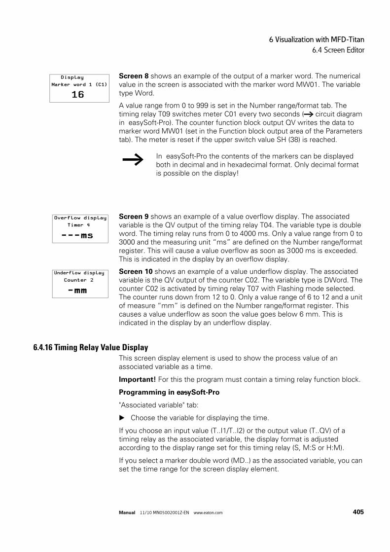
6 Visualization with MFD-Titan
6.4 Screen Editor
Manual 11/10 MN05002001Z-EN www.eaton.com 405
Screen 8 shows an example of the output of a marker word. The numerical value in the screen is associated with the marker word MW01. The variable type Word.
A value range from 0 to 999 is set in the Number range/format tab. The timing relay T09 switches meter C01 every two seconds (→ circuit diagram in easySoft-Pro). The counter function block output QV writes the data to marker word MW01 (set in the Function block output area of the Parameters tab). The meter is reset if the upper switch value SH (38) is reached.
Screen 9 shows an example of a value overflow display. The associated variable is the QV output of the timing relay T04. The variable type is double word. The timing relay runs from 0 to 4000 ms. Only a value range from 0 to 3000 and the measuring unit “ms” are defined on the Number range/format register. This will cause a value overflow as soon as 3 000 ms is exceeded. This is indicated in the display by an overflow display.
Screen 10 shows an example of a value underflow display. The associated variable is the QV output of the counter C02. The variable type is DWord. The counter C02 is activated by timing relay T07 with Flashing mode selected. The counter runs down from 12 to 0. Only a value range of 6 to 12 and a unit of measure “mm” is defined on the Number range/format register. This causes a value underflow as soon the value goes below 6 mm. This is indicated in the display by an underflow display.
6.4.16 Timing Relay Value DisplayThis screen display element is used to show the process value of an associated variable as a time.
Important! For this the program must contain a timing relay function block.
Programming in Soft-Pro
"Associated variable" tab:
Choose the variable for displaying the time.
If you choose an input value (T..I1/T..I2) or the output value (T..QV) of a timing relay as the associated variable, the display format is adjusted according to the display range set for this timing relay (S, M:S or H:M).
If you select a marker double word (MD..) as the associated variable, you can set the time range for the screen display element.
DisplayMarker word 1 (C1)
16
→ In easySoft-Pro the contents of the markers can be displayed both in decimal and in hexadecimal format. Only decimal format is possible on the display!
Overflow display Timer 4
---ms
Underflow display Counter 2
-mm

6 Visualization with MFD-Titan
6.4 Screen Editor
406 Manual 11/10 MN05002001Z-EN www.eaton.com
If the process value is outside of the range of values supported by the time range, an overflow or underflow will be indicated with an arrow and the following displays a b.
Visibility and Display change tabs → Section "6.4.2.3 General tabs for parameterizing a screen element“, page 372.
Example application:
The example program MFD-Titan-CP8.e60 contains in the German screen Funktion_DE_Zeitrelaiswertanzeige and in the English screen Function_EN_Timing_relay_valu_displ the Timing relay value indication element.
The MFD-Titan-CP10.e60 example program contains the display element in the multi-lingual screen Function_Timing_relay_valu_displ.
The output value of timing relay T01QV is shown above it. The resolution sss.ms is automatically matched to the set time range of the timing relay.
The following section describes the value entry elements.
6.4.17 Value EntryThis screen entry element enables you to enter numerical setpoint values during operation and thus make interventions in the process. This is done by entering the signal state via the associated set variable.
The MFD stores the entered value internally. The program processes the value and displays it until it is changed by the operator or the program. Without an operator entry this screen element functions like the numerical value screen element and therefore displays the value of the associated set variable.
At the beginning of the entry on the MFD, the entry field contains the last variable value. Pressing OK activates Selection mode in which you can use the cursor buttons to move between the value entry elements of a screen. If the screen contains several value entry elements, the entry element first added in the screen editor (indicated by the numbering of the screen element in the status line of easySoft-Pro) is selected first.
After the required entry element was selected, you activate Entry mode by pressing OK again.
Use the cursor buttons to select the number(s) to be changed and change the setpoint value.
Press OK once more to confirm the value entry and leave Entry mode.

6 Visualization with MFD-Titan
6.4 Screen Editor
Manual 11/10 MN05002001Z-EN www.eaton.com 407
Value and scaling range
The value range determines the range of values to be displayed. The MFD indicates an underflow if the values are below this range and an overflow if they are above it.
The scaling range enables the value range to be scaled. To do this, the lower value of the scaling range is assigned to the lower value of the value range and the upper value of the scaling range is assigned to the upper value of the value range. If no scaling range is defined, the MFD displays the value range.
Examples
If you wish to display the value range (0 to 255) for example from a counter as a percentage (0 to 100%), then enter 0 as the minimum value and 255 as the maximum value in the Value range area. Enter “%” as a unit of measure. Activate the Scaling range area and enter 0 as the minimum value and 100 as the maximum value.
If you wish to display the value range from 0 to 120 seconds, for example, from a timing relay in minutes (0 to 2 min), enter 0 as the minimum value and 120 as maximum value in the Value range area. Enter “min” as a unit of measure. Activate the Scaling range area and enter 0 as the minimum value and 120 as the maximum value.
Programming in Soft-Pro
Register Associated variable:
Enter here the Boolean variable for which you wish to set the value.
Number range/format tab:
You define the following in this tab:
• Value range.• Unit of measure.• Scaling Range.• Input format.
The display of the sign can be forced.
Visibility and Display change tabs → Section "6.4.2.3 General tabs for parameterizing a screen element“, page 372.
Application examples 1:
The example program MFD-Titan-CP8.e60 contains in the German screen Funktion_DE_Werteingabe and in the English screen Function_EN_Value_entry the Value entry indication element.
The MFD-Titan-CP10.e60 example program contains the Value entry display element in the multi-lingual screen Function__EN_Value_entry.

6 Visualization with MFD-Titan
6.4 Screen Editor
408 Manual 11/10 MN05002001Z-EN www.eaton.com
Application examples 2:
The ValueEntryProg_01.e60 example program shows other applications of this screen element.
ValueEntryProg_01.e60 (value entry)
The program consists of seven screens that you can select via cursor buttons Í and Ú. The screen change was defined in the button editor (→ Section "6.6 Button Editor“, page 417). While the MFD is in RUN state you can modify all the values that are processed by the program via the cursor buttons ú í Í Ú. The actual values are shown in the MFD's display.
In order to display values the MFD must firstly be switched to Selection mode. In Selection mode you can select the value entry element for the values you wish to change.
Press OK so that the MFD switches to Selection mode. Press ESC to exit Selection mode.
The selected value entry element will flash. If several entry elements are present you can select the required element with the cursor buttons ú í Í Ú (→ Screen 7).
Press OK in order to switch from Selection mode to Entry mode. Move to the required position with the cursor buttons ú and í, change the
value with the cursor buttons Í and Ú. Accept the modified value with OK. Pressing ESC will cause the previous
value to be retained. In both cases you will return to Selection mode and can exit this by pressing ESC.
The circuit diagram contains the timing relay T01 that triggers the counter C02. The counter switches the output Q1 to high when the upper set value SH is reached. The value of the counter function block output QV is transferred to the marker word MW06. The upper set value SH is associated with the marker word MW07 and the preset actual value SV with marker word MW05. During RUN mode the current data is stored in the marker words and new data is written there via the value entry elements. Input I2 can be used to reset the counter at any time. I1 (rising edge) is used to accept the value at marker word MW05 as a new preset actual value SV. As no value is stored in marker word MW07 (switch value for Q1) when the program is started, this is interpreted as switch value “zero” and the output Q1 is immediately set to “high”.
Screen 1 illustrates the value entry option via the set variable marker word MW 07 (switch value for Q1). The value entry element is shown enlarged on the display. A value range is defined from 0 to 9 999 in the Number range/format register and Allow Digit Selection is set as entry mode. The input I01 is selected with N/O contact bit logic on the Operability tab. The value is written to the marker word 7 and transferred by counter input SH. Q1 is high when the counter input value QV equals or is greater than the upper set value SH. If the actual value is already higher than the switch value, you can reset the counter via I2. Q1 switches immediately to low and is not set again until the switch value is reached.
100
Switch value Q1(OK)Actual value 99

6 Visualization with MFD-Titan
6.4 Screen Editor
Manual 11/10 MN05002001Z-EN www.eaton.com 409
Screen 2 illustrates the value entry option via the set variable marker word MW05 (preset actual value SV). After you have entered a new value this is written to the marker word MW05 by actuating I1. This is associated with the preset actual value SV of the counter C02. After the transfer, the actual value QV jumps to the entered SV value and counts on from there.
Figure 257: Transfer of value on closing of I1
Screen 3 shows an example of the Number range/format register, especially the Scaling range and Input Format r Allow Digit Selection. You can enter any value from 0.00 to 10.00 (allow digit selection). After I1 is closed, the preset actual value SV is transferred. After the transfer, the actual value QV jumps to the entered SV value and counts on from there. The maximum scaling range (10.00) is assigned to the maximum value range (9 999). The QV value thus switches to the value 10.00 when 1 is entered and 9999 is actuated.
Figure 258: Transfer of value with Allow digit selection
Screen 4 shows an example of the Number range/format register, and in particular the Scaling range and Input Format r Fixed Step Width. You can enter any value from 0.00 to 10.00 in step widths of 0.50 (fixed step width). After I1 is closed, the preset actual value SV is transferred. After the transfer, the actual value QV jumps to the entered SV value and counts on from there. The maximum scaling range (10.00) is assigned to the maximum value range (9 999). The QV value thus switches to the value 10.00 when 1 is entered and 9999 is actuated.
Set entry: 80 Transfer of value
Value entry = 10.00 QV value = 9 999
Set Entry(OK)80Transfer I1
QV 304
Set Entry(OK)80Transfer I1
QV 80
Allow digit selection Set input QV (OK)15 10.00
Allow digit selection Set input QV (OK) 9999 10.00

6 Visualization with MFD-Titan
6.4 Screen Editor
410 Manual 11/10 MN05002001Z-EN www.eaton.com
Figure 259: Transfer of value with Fixed Step Width
Screen 5 shows an example from the Visibility tab. If I4 is closed, the value entry element is made invisible. The N/O contact bit logic is set. If N/C contact bit logic was set, this would create a visible switch function. The element remains operable even when invisible, and value entry is still possible.
Figure 260: Switch value entry element invisible
Screen 6 shows an example using the Operability tab. The same Visibility setting is used as in screen 5. Closing I3 will disable the entry function (N/O contact bit logic). If the value entry element is disabled, you can still select it (it flashes) but the Entry mode (change values) is disabled. If the value entry element is in Entry mode when I3 is closed, the MFD switches automatically to Selection mode. If N/C contact is set as bit logic, entry is only possible if I3 is actuated. I4 switches the value entry element to invisible, however, it still remains operable allowing values to be changed.
Figure 261: Value entry element disabled
Value Entry Transfer QV value
Set value visible Set value invisible
I3 not actuated I3 actuated
Step Width Set input QV (OK) 16 8.50
Step Width Set input QV (OK) 8500 8.50
Set value entry invisible QV via I4 299 1037
Set value entry invisible QV via I4 299
Set value entry Blocked QV via I3 249 1037
Set value entry Blocked QV via I3 249 1037

6 Visualization with MFD-Titan
6.4 Screen Editor
Manual 11/10 MN05002001Z-EN www.eaton.com 411
6.4.18 Timing relay value entryThis screen entry element enables to make a later change to the time setpoints at inputs I1 and I2 of the timing relay function block (T ..). A constant (NU) must be set at the input to be changed.
Requirement for using the screen entry element: The program must already contain the timing relay function block. The input T ..I1 or T ..I2 to be assigned parameters must be set with a constant (NU). Inputs without assigned parameters cannot be edited via this screen entry element.
The display format is adjusted to the timing range set for this timing relay (S, M:S, H:M).
Programming in Soft-Pro
"Associated variable" tab:
Choose here in the Number list box the function block T 01...32 to be changed and in the FB Parameters list box the input T ..I1 or T ..I2 to be changed.
Visibility and Display change tabs → Section "6.4.2.3 General tabs for parameterizing a screen element“, page 372.
Example application:
The example program MFD-Titan-CP8.e60 contains in the German screen Funktion_DE_Zeitrelaiswerteingabe and in the English screen Function_EN_Timing_relay_valu_en the Timing relay value entry element.
The MFD-Titan-CP10.e60 example program contains the screen entry element in the multi-lingual screen Function_Timing_relay_valu_entry.
The input value I2 of the timing relay T02 is set via this entry element. The resolution sss.ms is automatically matched to the set time range of the timing relay.

6 Visualization with MFD-Titan
6.4 Screen Editor
412 Manual 11/10 MN05002001Z-EN www.eaton.com
6.4.19 Date and time entryThis screen element can be used to change the date and time of the device real-time clock. If the device is in RUN operating state, the operator can carry out these changes with the buttons of the MFD.
The entry element is shown on the screen in a Normal font size, i.e. with a simple font size with up to 16 characters per line.
Programming in Soft-Pro
Element specific tabs - Date formats tab:
In the Country settings list choose the language in order to define the arrangement of day, year and month.
The time is shown in the format hh:mm.
The different country settings are shown in the table in the easySoft-Pro Help system.
"Synchronize Date and Time via NET" check box:
When this option is active, the local date and time change via this screen entry element are transferred to the device real-time clocks on all NET stations. These are synchronized with the modified value.
The option has the same effect as the SC01 (Send Clock) function block, which sets the date and time of all stations on the NET to the same value.
Visibility and Operability register: → Section "6.4.2.3 General tabs for parameterizing a screen element“, page 372.
Example application:
The example program MFD-Titan-CP8.e60 contains in the German screen Funktion_DE_Datum/Zeiteingabe and in the English screen Function_EN_Date_a._time_entry the Date and time entry element.
The MFD-Titan-CP10.e60 example program contains the screen entry element in the multi-lingual screen Function_Date_a._time_entry.

6 Visualization with MFD-Titan
6.4 Screen Editor
Manual 11/10 MN05002001Z-EN www.eaton.com 413
6.4.20 Weekly timer inputsThis screen entry element enables you to make later changes to the on or off times for one of the four channels (A, B, C and D) of the weekly timer function block (HW ..). In order to change the parameter set of a channel (on and off) completely, you therefore require two of these screen entry elements.
If the device is in RUN operating state, the operator can make the changes via the pushbuttons of the MFD. He can change the weekday (DY.), hour and minute of the on and off time. The new value entered is permanently stored in the program.
Requirement for using the screen entry element: The weekly timer function block is already incorporated in the program and the channel to be modified has already been assigned parameters. Channels that have not been assigned parameters cannot be modified!
Programming in Soft-Pro
Associated variable tab:
Choose here in the Number list box the function block HW 01...32 to be changed and in the FB Parameters list box the channel A...D to be changed.
The channel A…D to be changed must be set in the program.
In the Time On/Off area use the ON or OFF option buttons to define whether the on or off time of the selected channel can be changed via this screen entry element.
Selecting the ON option activates the channel parameters DY1 and ON of the assigned weekly time clock.
Selecting OFF activates the channel parameters DY2 and OFF.
If required use the Country settings list box to change the display format of weekday, hour and minute of the on and off time in the screen element.
Visibility and Display change tabs → Section "6.4.2.3 General tabs for parameterizing a screen element“, page 372.
Example application:
The example programs MFD-Titan-CP10.e60 and MFD-Titan-CP8.e60 contain the Weekly timer entry element.
When the Function_7-day_time_switch_entry or Funktion_DE_Wochenzeitschaltuhr screens are displayed with the ON option active, the ON time of function block HW01, channel A can be changed during the run time. The Function_7-day_time_switch_ent_2 or Funktion_DE_Wochenzeitschaltuhr_2 screens with the OFF option active enable the OFF time of HW01, channel A to be changed.

6 Visualization with MFD-Titan
6.4 Screen Editor
414 Manual 11/10 MN05002001Z-EN www.eaton.com
6.4.21 Year time switch entryThe screen element allows you to make later changes to the on and off time for each of the four channels (A, B, C and D) of the year time switch (HY) function block. In order to change the parameter set of a channel (on and off) completely, you therefore require two of these screen entry elements.
If the device is in RUN operating state, the operator can make the changes via the pushbuttons of the MFD. Here he can change the day (DD), month (MM) and year (YY) of the on and off time.
The new value entered is permanently stored in the program.
Requirement for using the screen entry element:
The year time switch function block must be already incorporated in the program and the channel to be modified must have already assigned parameters. Channels that have not been assigned parameters cannot be modified.
Programming in Soft-Pro
"Associated variable" tab:
Choose here in the Number list box the function block HW 01...32 to be changed and in the FB Parameters list box the channel A...D to be changed.
In the Time On/Off area use the ON or OFF option buttons to define whether the on or off time of the selected channel can be changed via this screen entry element.
By selecting ON mode, the channel parameters day (DD), month (MM) and year (YY) are activated for changing the on time of the assigned year time switch.
Selecting OFF activates the same channel parameters for changing the off time.
If required use the Country settings list box to change the display format of weekday, hour and minute of the on and off time in the screen element.
Visibility and Display change tabs → Section "6.4.2.3 General tabs for parameterizing a screen element“, page 372.
→ If only dashes -- --:-- are shown in the date format even though the screen entry element is large enough, this means that the program does not contain an HY .. function block for the selected operand number.

6 Visualization with MFD-Titan
6.4 Screen Editor
Manual 11/10 MN05002001Z-EN www.eaton.com 415
Example application:
The MFD-Titan-CP10.e60 and MFD-Titan-CP8.e60 example programs contain screens with the Year time switch entry element.
When the Function_Year_time_switch_entry or Funktion_DE_Jahreszeitschaltuhr screens are displayed with the ON option active, the ON time of function block HY01, channel A can be changed during the runtime. The Function_Year_time_switch_ent_2 or Funktion_DE_Jahreszeitschaltuhr_2 screens with the OFF option active enable the OFF time of HY01, channel A to be changed.

6 Visualization with MFD-Titan
6.5 Button operation on the MFD-Titan
416 Manual 11/10 MN05002001Z-EN www.eaton.com
6.5 Button operation on the MFD-Titan
The following table shows the function of the MFD function keys in the visualization. Pressing the * pushbutton switches you from the Status display to the visualization.
Table 41: Function of the function keys in the visualization of the MFD
6.5.1 Operating principle in the visualizationIn RUN mode the operator can use the cursor buttons in the visualization to enter a variable or a setpoint value. For this the cursor buttons have basic functions if new functions were not assigned using the button element:
• Move (Selection mode).• Enter (Entry mode).
The current mode is indicated by the appearance of the flashing cursor.
Both modes can be closed again by pressing the ESC button.
6.5.1.1 Selection mode in the visualizationRequirement: The visualization must show a screen that contains at least one screen entry element.
As an operator you press the OK button in the visualization in order to activate Selection mode.
The screen entry element is shown as an inverse flashing rectangle. If the screen contains several entry elements, the element that was edited first is always selected.
In Selection mode use the ú í Í Ú buttons to position the cursor on a screen entry element if the screen contains several of them.
Then press the OK button to move from Selection mode to Entry mode. Values can only be entered or modified in Entry mode.
Cursor up Without function (can be overwritten with button element)
Cursor down Without function (can be overwritten with button element)
Cursor left Without function (can be overwritten with button element)
Cursor right Without function (can be overwritten with button element)
OK Move from the visualization to the Selection mode (can be overwritten with button element)
DEL Without function (can be overwritten with button element)
ESC Without function (can be overwritten with button element)
ALT Without function (can be overwritten with button element)
* -Pushbutton Move from the visualization back to the Status display (can be overwritten with button element)
ALT + DEL Without function

6 Visualization with MFD-Titan
6.6 Button Editor
Manual 11/10 MN05002001Z-EN www.eaton.com 417
6.5.1.2 Entry mode in the visualizationThe selected digit or entry location in a screen entry element is always displayed flashing. With a screen menu entry element, the name of the first selectable screen flashes.
Position the cursor with the ú í buttons on the entry location and use the Í Ú buttons to select the value.
Accept the entered or modified value with OK. Now exit the active Selection mode with ESC. With screen menu entry elements use the cursor buttons to scroll to the
required screen indicated by its name. Press OK to enter this screen directly.
6.6 Button EditorFor fast access to the visualization elements and variables you can assign new functions to the pushbuttons of the MFD. For this you can create a macro for each operator pushbutton by assigning several functions consecutively.
The modified button function can be used during the visualization. If you return the MFD to the Status display, the basic functions of function key are restored.
You use button elements in the button editor to assign new button functions to the operator buttons.
The Button editor provides the following button elements, and the list below shows in round brackets the device version number of an MFD-CP8 from which this is possible:
Information in square brackets indicates the operating system [OS-] version number of an MFD-CP10..., from which the button element can only be used for these devices.
Button element → Page
Operable Screen Element (1) 419
Display Backlight (1) 419
Display contrast [ CP10, OS-Ver. 1] 420.
Screen Change (1) 369
Password Logout (1) 434
Set Variable to Fixed Value (1) 422
Decrement Variable (1) 423
Increment Variable (1) 424
Changeover Relay (1) 426
Disable Change to Status Display (5) 426
P Button Function (5) 427
Go to Previous Screen (5) 428

6 Visualization with MFD-Titan
6.6 Button Editor
418 Manual 11/10 MN05002001Z-EN www.eaton.com
6.6.1 How to Assign a Pushbutton Element to a PushbuttonPrerequisites
• The screen in which the new button function is to be defined must be selected in Visualization view.
• The button editor must be opened. • The operator button to be assigned the new function must be selected
e.g. DEL.
Figure 262: Preselected DEL pushbutton that can be assigned with pushbutton elements
Drag a button element, e.g. Set variable to fixed value and drop it into the Button functions list underneath the symbolized buttons in the Workbench window.
You can drag several button elements to the Button functions list (up to 255) and thus assign them to an operator button. This for example enables you to assign several variables to one fixed value with one button actuation.
Associate the button element with the suitable operand, e.g. MW4 and complete the parameterization, for example, with the set value 4711.
If you then press the DEL pushbutton in the visualization, MW4 is set to the value 4711.
Disable Selection Mode (5) 429
Jump Label (5) 429
Conditional Jump (5) 430
→ The button assignment is screen-oriented. Functions can therefore be assigned to operator buttons for any particular screen.This feature is then very useful if, for example, you create several screens for your visualization application and you want the operator to be able to move between them by pressing a particular button.
Button element → Page
*
DEL ALT
ESC
OK

6 Visualization with MFD-Titan
6.6 Button Editor
Manual 11/10 MN05002001Z-EN www.eaton.com 419
6.6.1.1 Deleting a button elementIn easySoft-Pro you delete a pushbutton element from the Button functions list with the Del pushbutton.
The following shows a function description of the button elements. Refer to the easySoft-Pro Help for information on how to assign these with parameters.
6.6.2 Select operable screen elementThe Select operable screen element function enables the user to reach a value entry element directly, e.g. in the Value entry screen element, (→ section “6.4.17 Value Entry”, page 406). The Entry mode required is activated automatically.
Programming in Soft-Pro - parameterization
In the "Screen" list box: select the screen with the required value entry element.
In the "Value entry screen element": select the required value entry element - indicated by the number of the screen element in the easySoft-Pro status line - if the screen contains several of these elements.
This completes the parameterization.
Button element during operation
During operation the user:
• selects the button element with the assigned function key • uses the cursor buttons to select the digit(s) to be changed and the new
setpoint value.• uses OK to confirm the value entry and exit Entry mode.
6.6.3 Display BacklightThe display backlight function enables the operator to set the display backlight brighter in 25% stages between 0%-100 %, or with a different parameter setting from 100%-0%. Another pushbutton is required to adjust the display backlight in the opposite direction.
6.6.3.1 Changing the display backlight via LE1You can use the LE1 output operand to change the backlight for the display and the front plate buttons of the MFD in RUN operating state.
The cyclical setting and resetting of the LE1 output operand in the circuit diagram can be used, for example, to implement flash functions.

6 Visualization with MFD-Titan
6.6 Button Editor
420 Manual 11/10 MN05002001Z-EN www.eaton.com
Table 42: Changing the backlight via LE1
Programming in Soft-Pro - parameterization
Under Gradual display adjustment set the required brighter or darker setting.
6.6.4 Display contrastAvailable on MFD-CP10....
The Display contrast function enables the operator to set the display contrast higher or lower during operation with the assigned operator button. Another button assigned to the Display contrast function is required to adjust the display contrast in the opposite direction.
Programming in Soft-Pro - parameterization
Under Gradual display adjustment set the required brighter or darker setting.
6.6.5 Screen changeThis function enables the operator to switch between several screens. To do this you must assign the Screen change function to an operator button in each screen.
Programming in Soft-Pro
In addition to the above requirement, the use of this button element requires at least two screens between which the function is toggled.
Parameter definition
In the Screen: field select the required target screen.
This completes the parameterization.
Status of LE1 Backlight
0 switched on, according to the brightness level set in the MFD System menu
1 Switched off
→ The "Screen Change" function is a closing function. The current screen is closed after this function has been executed and so no other operations are possible in it.This means that this function should always be the last function in the Button functions list when a button is assigned functions. This must also be taken into account when later reversing the order with the Up / Down buttons.

6 Visualization with MFD-Titan
6.6 Button Editor
Manual 11/10 MN05002001Z-EN www.eaton.com 421
6.6.6 Password logoutThe "Password logout" function is used by the operator to cancel the access rights granted for a protected screen after the password is entered. The password entry window is then displayed. In this way, the next operator then has to enter a valid password in order to display the screen.
Programming in Soft-Pro
Besides the above requirements for using the button element you must have edited at least one password with a logout time for a screen with a value entry element.
Parameter definition
In the Logout of area click the check box for the password that will lose its access rights after the assigned pushbutton is pressed.
This completes the parameterization.
Example
Requirements:
• A password with a logout time of 30 minutes was entered for screen 2.• Screen 2 contains a value entry element.• The Password logout function was assigned to the < pushbutton.
During operation: You can access Screen 2 after entering the password. You then have 30 minutes to enter or change a value without a password request being output. If you decide after 5 minutes that the value no longer has to be changed and leave your workplace, it may be possible that an unauthorized person changes the value in the remaining 25 minutes. To prevent this you can reset the logout time using the < button. A new password request is generated. The operator then has 2 options:
• Re-enter the password so that the screen is displayed again. • Press ESC to move to another screen.
On MFD-CP8... devices up to device version number 04 the display of the current screen is continued instead of the displaying the password entry window. The operator must re-enter the password before he can start a value entry or actuate an operator button assigned with functions.
If you have also added other functions in addition to the password logout to the "Button functions" list which the MFD is required to execute automatically in succession, these other functions are also processed after the password logout is completed.

6 Visualization with MFD-Titan
6.6 Button Editor
422 Manual 11/10 MN05002001Z-EN www.eaton.com
When moving to a password protected screen using the "Screen Change" function, the MFD will show the password entry window. To display the screen you must enter the correct password.
On MFD-CP8... devices up to device version number 04 the new screen is displayed immediately for the "Screen Change" function. You only have to enter the password if you wish to make a value entry or actuate an function key that is assigned functions.
If at another time an operator access authorization is achieved by entering an alternative password, the actuation of this button will not end this logout time.
6.6.7 Set variable to fixed valueThis function enables the user during operation to set the value of the assigned operand with the specified value by pressing a button.
Possible operands
Boolean operands (bit variable type):
• LE• M • Q• S• Function block inputs; the button element acts on the input like the
contact of contactor.
Byte and multiple byte operands
• Byte variable type: MB 01 - 96• Word variable type: MW 01 - 96 and analog output QA• DWord variable type: MD 01 - 96 and function block inputs (setpoints).
CAUTION
Ensure that the Boolean operand or function block input used here is not being accessed at the same time by the circuit diagram. These operands must not therefore be used again in a coil field.In the event of dual access, the operand always takes on the state of the last completed access. The button actuation of the operator may therefore be immediately undone by the circuit diagram.

6 Visualization with MFD-Titan
6.6 Button Editor
Manual 11/10 MN05002001Z-EN www.eaton.com 423
Function
During operation the new value is accepted by the device by pressing the assigned button and is retained until it is overwritten or until the device is switched off.
The following operands also retain the value after the device is switched back on:
• function block inputs that are associated with a constant (NU).• retentive markers (M.., MB.., MW.., MD..).
Programming in Soft-Pro - parameterization
First select the type (bit, byte, word, Dword) of the set variable to be changed in the Variable type area.
In the Variable to be set area, select the set variable which is to be set to the specified value by button actuation.
Finally enter the value in the Set variable with area with which the variable is to be set.
This completes the parameterization.
6.6.8 Decrement Variable This function enables the user during operation to reduce the value of the assigned operand by the specified value by pressing a button.
Possible operands
Byte and multiple byte operands
• Byte variable type: MB 01 - 96,• Word variable type: MW 01 - 96 and analog output QA,• DWord variable type: MD 01 - 96 and function block inputs (setpoints).
→ From MFD-CP8... devices with device version number 05 and MFD-CP10... devices, the setpoint value on a function block input can be set to a fixed value.Only the function block inputs (DWord variable type) that are associated with a constant (NU) can be set to a fixed value.
→ The setpoint value on a function block input can be decremented on MFD-CP8... devices with device version number 05 or higher and MFD-CP10... devices.Only the function block inputs (DWord variable type) that are associated with a constant (NU) can be decremented.

6 Visualization with MFD-Titan
6.6 Button Editor
424 Manual 11/10 MN05002001Z-EN www.eaton.com
Function
During operation the value is decremented by pressing the assigned button and is retained until it is overwritten or until the device is switched off.
The following operands also retain the value after the device is switched back on:
• function block inputs that are associated with a constant (NU).• retentive markers (MB.., MW.., MD..).
Programming in Soft-Pro - parameterization
First select the type (byte, word, double word) of the set variable to be changed in the Variable type area.
In the Variable to be set area, select the set variable with the value to be decremented by button actuation.
Finally enter in the Decrement variable area the step width by which the variable value is to be decremented.
The default value is 1. Only positive values can be selected.
This completes the parameterization.
6.6.9 Increment VariableThis function enables the user during operation to increase the value of the assigned operand by the specified value by pressing a button.
Possible operands
Byte and multiple byte operands
• Byte variable type: MB 01 - 96,• Word variable type: MW 01 - 96 and analog output QA,• DWord variable type: MD 01 - 96 and function block inputs (setpoints).
→ If the operator reduces the value of the associated variable during operation by button actuation, the MFD prevents any possible undershoot of the permissible value range and works with the lower limit value.If, for example, the Byte variable type was decremented by button actuation so that the value is less than zero, the device would operate with the value zero.

6 Visualization with MFD-Titan
6.6 Button Editor
Manual 11/10 MN05002001Z-EN www.eaton.com 425
Function
During operation the value is incremented by pressing the assigned button and is retained until it is overwritten or until the device is switched off.
The following operands also retain the value after the device is switched back on:
• function block inputs that are associated with a constant (NU).• retentive markers (MB.., MW.., MD..).
Programming in Soft-Pro - parameterization
First select the type (byte, word, double word) of the set variable to be changed in the Variable type area.
In the Variable to be set area, select the set variable with the value to be incremented by button actuation.
Finally enter in the Increment variable area the step width by which the variable value is to be incremented.
The default value is 1. Only positive values can be selected.
This completes the parameterization.
→ The setpoint on a function block input can be incremented on MFD-CP8... devices with device version number 05 and higher and MFD-CP10... devices.Only the function block inputs (DWord variable type) that are associated with a constant (NU) can be incremented.
→ If the operator increases the value of the associated variable during operation by button actuation, the MFD prevents any possible overshoot of the permissible value range and works with the upper limit value.If, for example, the Byte variable type was incremented by button actuation so that the value is greater than 255, the device would operate with the value 255.

6 Visualization with MFD-Titan
6.6 Button Editor
426 Manual 11/10 MN05002001Z-EN www.eaton.com
6.6.10 Changeover relayThe changeover relay function enables the operator to negate the state of a Boolean variable or a Boolean function block input during operation by pressing a button.
Possible operands
Boolean operands (bit variable type):
• LE• M • q• S• Function block inputs, the button element acts on the input as a coil with
the contactor function.
Programming in Soft-Pro - parameterization
First select in the Negate bit variable area, Associate via list box: Boolean operand or function block inputs as associated variable.
Finally select the operand.
This completes the parameterization.
6.6.11 Disable Change to Status DisplayWith this button element, you can disable the predefined function of the Mode or * button on the MFD, via which you return to the Status display from the visualization. This prevents the possibility of manipulations on the operating state or program of the MFD.
This pushbutton element is not required if you have already assigned another pushbutton function to the mode pushbutton.
Programming in Soft-Pro
Requirement for using the button element:
• You must use an MFD-CP8... device from device version number 05 or an MFD-CP10... device.
• You must have edited at least one screen from which a switch to the Status display is not permissible.
• You must also have switched to the button editor.
CAUTION
Ensure that the Boolean operand or function block input used here is not being accessed at the same time by the circuit diagram. These operands must not therefore be used again in a coil field.In the event of dual access, the operand always takes on the state of the last completed access. The button actuation of the operator may therefore be immediately undone by the circuit diagram.

6 Visualization with MFD-Titan
6.6 Button Editor
Manual 11/10 MN05002001Z-EN www.eaton.com 427
First select the screen from which Status display should not be accessible.
Left-click the Mode pushbutton. Then drag the Disable Change to Status Display button element into the
Button Functions list box.
Parameter definition
No parameters are required for this button element.
6.6.12 P button functionThe P pushbutton operands are used in the circuit diagram as contacts, so that you can switch using the cursor buttons during operation,→ Section "4.7.9 Switching with the Cursor Buttons“, page 172.
As soon as you have edited a screen on the MFD in which different functions can be assigned to the operator buttons, the P buttons lose initially this contact function. When used in the circuit diagram they take on the value 0.
In order to use P buttons for switching in a visualization and wire them as contacts, assign each of these buttons simply to the P button function element. In other words: This P button function causes the device to also respond in the visualization to the actuation of a cursor button in exactly the same way as if it was in the Status display.
Function
The cursor buttons ú Í í Ú are assigned to the operands P01 - P04 in this order (only with MFD devices with display module and function keys)
The other operator buttons on the MFD-CP10... can also be used as additional inputs. The following table shows the assignment of the other operator buttons of the MFD-CP10....
P02
P01
P04
P03
Contact Operator Button
P05 OK
P06 ESC
P07 DEL
P08 ALT
P09 *-pushbutton (mode pushbutton)
→ The P button function is an exclusive function. It should therefore be entered separately in the Button functions list. The device will ignore any other button elements that you drag into the Button functions list.

6 Visualization with MFD-Titan
6.6 Button Editor
428 Manual 11/10 MN05002001Z-EN www.eaton.com
Under the following conditions the cursor buttons Í Ú ú í and the other operator buttons of the MFD-CP10... will retain their previous function in the visualization even with the P button function active:
• If the device is in Entry mode and you wish to define setpoints, for example, using Value entry screen elements.
• If the device is in element selection mode and you wish to select a screen element.
• If the device is in the Screen password entry mode.
Programming in Soft-Pro
Requirement for using the button element:
• You must use an MFD-CP8... device from device version number 05 or an MFD-CP10... device and must have activated the "P pushbuttons" option in the "System settings" tab.
• You must have edited at least one screen and have switched to the button editor.
First select the required screen. Then left-click the cursor button to be enabled, e.g. the > pushbutton. Then drag the P button function in the Button functions list.
Parameter definition
No parameters are required for this button element.
6.6.13 Go To Previous ScreenThe Go to previous screen function enables you to undo the last screen change by button actuation during operation.
Function
With every screen change, the device remembers the previously displayed screen, regardless of whether the change was initiated by the operator or by a screen actuation in the circuit diagram. Thus function is only used sensibly when the change is initiated by the operator.
→ The Go to previous screen function is a closing function. Because the actual screen is closed after this function is executed, no further actions are possible that are associated with this screen. This means that this function should always be the last function in the Button functions list when a button is assigned functions. This must also be taken into account when later reversing the order with the Up / Down buttons.

6 Visualization with MFD-Titan
6.6 Button Editor
Manual 11/10 MN05002001Z-EN www.eaton.com 429
Programming in Soft-Pro
Requirement for using the button element:
• You must use an MFD-CP8... device from device version number 05 or an MFD-CP10... device.
• You must have edited at least two screens and have switched to the button editor.
First select the required screen. Then left-click the required pushbutton. Then drag the button element to the Button functions list.
Parameter definition
No parameters are required for this button element.
6.6.14 Disable Selection ModeThis function is used to disable on the MFD the predefined function of the OK pushbutton via which the operator enters Selection mode.
Function
This function prevents unauthorized value entries in the screen entry elements of the associated screens.
This button element is not required if you have already assigned another button function to the OK button.
Programming in Soft-Pro
Requirement for using the button element:
• You must use an MFD-CP8... device from device version number 05 or an MFD-CP10... device.
• You must have edited at least one screen and have switched to the button editor.
First select the required screen. Then left-click the OK button. Then drag the Disable Selection Mode button element into the Button
Functions list box.
Parameter definition
No parameters are required for this button element.
6.6.15 Jump LabelRequirement: You must use an MFD-CP8... device from device version number 05 or an MFD-CP10... device.
The sole task of the Jump label function is to define the destination for the Conditional jump button function. The combination of these two button functions enables sections of the button functions list to be skipped depending on the status of a user-defined Boolean operand.

6 Visualization with MFD-Titan
6.6 Button Editor
430 Manual 11/10 MN05002001Z-EN www.eaton.com
6.6.15.1 Programming in Soft-ProRequirement for using the button element:
• You must use an MFD-CP8... device from device version number 05 or an MFD-CP10... device.
• You must have edited at least one screen and have switched to the button editor.
• The Button functions list must contain several button elements.
Then left-click the required pushbutton. Then drag the Jump label function in the Button functions list behind the
button elements to be skipped.
Parameter definition
Define the jump destination within the list using the number in the Jump label list box.
This completes the parameterization.
6.6.16 Conditional JumpThe Conditional Jump function enables parts of the Button functions list to be skipped according to the state of a freely selectable Boolean operand. The state of this operand therefore determines by which function keys of the MFD newly assigned functions are called or not.
Function
The Conditional Jump function can only be used in conjunction with the Jump Label function. Both functions form a bracket for the button elements to be skipped. Only forward jumps are possible.
Programming in Soft-Pro
Requirement for using the button element:
• You must use an MFD-CP8... device from device version number 05 or an MFD-CP10... device.
• You must have edited at least one screen and have switched to the button editor.
→ If you later add the Conditional Jump and Jump Label functions to the button functions list, use the Up/Down buttons to place the functions in the required positions.

6 Visualization with MFD-Titan
6.6 Button Editor
Manual 11/10 MN05002001Z-EN www.eaton.com 431
First select the required screen. Then left-click the required pushbutton, e.g. the ESC pushbutton. Then drag the Conditional Jump button element function to the Button
functions list in front of the button function to be skipped. If necessary, position the function in the Button function list using the
Up/Down buttons.
Example
The Increment variable button function is to be skipped and thus made inactive. The Button function list will then have the following appearance:
Parameter definition
In the Conditional Jump tab, assign a Boolean operand to the Conditional Jump button element, for example input I1.
If voltage is applied to this input, the Increment variable button element cannot be executed by actuating the ESC button.
• Boolean operands The Operand and Number fields are active. You can choose a Boolean operand as an operand.
Figure 263: Window Conditional Jump
• Function block inputs and outputsThe Operand, Number and FB Parameter fields are active. In the Operand field select the function block type, in the Number field the number and in the FB Parameter field the input or output.
This completes the parameterization.
Conditional Jump 1
Increment Variable
Jump Label 1

6 Visualization with MFD-Titan
6.7 Password Protecting Screens
432 Manual 11/10 MN05002001Z-EN www.eaton.com
6.7 Password Protecting Screens
The access authorisation for an installation managed by a visualization application can be controlled with the password protection function. For this you protect a screen with a password. The password responds to access to the screen, e.g. by a screen change, in the following way:
• On MFD-CP8... devices up to device version number 04 the protected screen is shown. However the operator has no access to screen elements via which a value entry can be made.
• On MFD-CP8... devices from device version number 05 and MFD-CP10... devices, the password entry screen is shown instead of the protected screen. The screen is only shown after the password is entered.
You can configure up to three passwords. During operation, any of the three passwords entered will allow access to the screen. In this way, up to three operators can access the screen independently of each other.
Valid passwords
5-digit decimal number 1 – 99999, without letters. A 0 corresponds to a deleted password. Changing passwords on the MFD at a later time is not possible.
6.7.1 Configure passwordYou configure a password and the logout time in easySoft-Pro via Visualization View -> Screen overview -> Passwords tab. This is described in the Help.
6.7.2 Language adaption of the title text "PASSWORD ENTRY:"When using an MFD-CP10... the user can adapt the PASSWORD ENTRY title text shown in the password request screen to the language used. The entry option is provided in the existing Passwords tab.
Activate the option Language Adaption. In the Language selection list box choose one of the languages defined in
the Languages tab, such as English, and enter the translated title text (max. 16 characters) “ENTER PASSWORD” in the Text: field.
If the Default text option is selected, as with the MFD-CP8... - the menu text present in the device is used.
→ The password protection for screens must not be confused with the system password protection, which is used for calling the System menu functions, → section “8.1 Safety”, page 445 . The password request function is not factory set in easySoft-Pro.

6 Visualization with MFD-Titan
6.7 Password Protecting Screens
Manual 11/10 MN05002001Z-EN www.eaton.com 433
6.7.2.1 Accessing a password protected screenOn MFD-CP8... up to version number 04
The password is requested if you start a value entry or actuate an operator button that is assigned function. The screen protected by the password is already displayed on the device. This password concept allows the change to the protected screen but then prevents any unauthorized operations.
The password is requested once more when further operator entries are required after the logout time for the password has elapsed.
On MFD-CP8... from version number 05 and on MFD-CP10...
On MFD-CP8... devices from device version number 05 and MFD-CP10... devices, the password request appears in the password entry window already when the protected screen is called. This screen will not be displayed until the correct password has been entered.
The request must always be repeated if:
• the logout time for the password has elapsed. • the logout time was ended by the operator (Password logout function). • a protected screen is to be activated from the circuit diagram (via screen
control)
6.7.3 Logout TimeIf you have opened a screen using the password entry, you can then, for example, carry out a value entry. The logout time is started after the password is entered. You can make several entries during this logout time without having to re-enter the password. You can move from this screen to another one and then return to the original screen without a password entry being necessary.
6.7.3.1 Configure Logout TimeAfter you have entered the password in the tab Screen Overview -> Passwords, you can also enter the logout time (0, 1 - 255 minutes) in the same line. A logout time of 0 minutes means the time for which the password is valid does not elapse. The access rights to this current screen after entering the password is retained until the next time that the device is switched to STOP.

6 Visualization with MFD-Titan
6.7 Password Protecting Screens
434 Manual 11/10 MN05002001Z-EN www.eaton.com
6.7.4 Password entry in runEnter as password the fixed maximum of five numbers in the password entry window.
Figure 264: Password entry window
To enter the password use the cursor buttons Í Ú ú í, the OK button and the ESC button. After an incorrect password entry any number of further attempts are possible. You can cancel password entry with the ESC button, however, the required access will still remain disabled.
In line 2 enter the five password digits. The first digit is already pre-assigned with 0. For example enter digits 0 0 0 5 4 for the password 54.
Line 3 shows the password entry window in square brackets with which one of three possible passwords can open the current screen. Passwords 1 and 3 were configured in the above figure.
Complete the correct password entry with the OK pushbutton.
Screen access is retained:
• Until the defined logout time has elapsed.• Until an operator button assigned with the Password logout function was
pressed.• Until the MFD switches to STOP operating mode.
Use the ESC pushbutton to cancel the password entry. However, screen access will still be disabled. The screen to be displayed after an abort depends on the setting and the version of the MFD used (→ After abort PW entry in the easySoft-Pro Help).

6 Visualization with MFD-Titan
6.7 Password Protecting Screens
Manual 11/10 MN05002001Z-EN www.eaton.com 435
6.7.5 Schematic procedure for password entry by the operator
Figure 265: Password entry
a Operator entry Move to a different Screen
b Is the Password request active function activated in the Passwords tab?
c Is the screen password protected? You activate password protection separately for each screen by selecting Yes in the PW-x field of the Screens parameter table.
d Has the password been entered correctly and has OK been pressed?
e Has the password entry been aborted with ESC?
f Has an alternative screen in the event of an abort with ESC been defined?
g The previous screen will continue to be displayed. Password entry is possible again.
h The alternative screen is shown (only from device version number 05).
i The protected screen is shown.
j End of screen change.
⑥
①
②
③
④
⑤
⑦
⑧
⑨
⑩
Yesno
Yesno
Yesno
noYes
noYes

6 Visualization with MFD-Titan
6.7 Password Protecting Screens
436 Manual 11/10 MN05002001Z-EN www.eaton.com

7 The network Net
7.1 Introduction network Net
Manual 11/10 MN05002001Z-EN www.eaton.com 437
7 The network Net
7.1 Introduction network NetThe easyNet network, termed the NET in the following document, is based on the CAN (Controller Area Network) serial bus system. CAN complies with the ISO 11898 standard.
The NET is designed for up to 8 stations.
Using the NET you can:
• Process additional inputs and outputs.• Implement faster and improved control using decentralised programs.• Synchronise date and time• Read and write inputs and outputs.• Send values to other stations.• Receive values from other stations.• Load programs from or to any station.
NET stations can be allMFD devices with a network connection (MFD-..-NT).
Figure 266: Mixed operation of NET stations
→ Distribute the tasks over several devices that exchange the data between each other via NET: easy800 or MFD devices for open-loop and closed-loop control and MFD devices for display and HMI tasks.
easy800 easy800
MFD-80-B MFD-CP4...
MFD-...-NTeasySafety
MFD-...-NT
easy800 (NET-ID 8)
easy800
easy800(NET-ID 1)
PC
easySoft-Pro easySoft-Safety

7 The network Net
7.1 Introduction network Net
438 Manual 11/10 MN05002001Z-EN www.eaton.com
Only the physically first NET station that is located at the beginning of the network manages the configuration and commissioning of the NET. In this way, the commissioning of NET stations is very simple. Apart from the installation with prefabricated cables, this only requires the following for the standard “loop through” topology:
• Definition of the first NET station by assigning NET ID 1 and the possible necessary modification of the baud rate in the NET PARAMETERS menu.
• Creation of the station list with automatic assignment of the NET IDs for the connected devices in the STATION menu.
• Configuration via the CONFIGURATION menu.
Further information on the configuration of the NET can be found on page 127.
Commissioning is even simpler when using easySoft-Pro. Information on this is provided in the Online Help of easySoft-Pro.
7.1.1 Transfer behavior of the NET stationsIn addition to the process that runs the program, a device with a NET connection also runs a parallel communication process that controls the exchange of network data.
Before every program cycle the network data is written from the NET receive buffer to the operand image of the program. The program runs through the next cycle with this data. At the end of the program cycle, the updated network data is written from the operand image to the NET send buffer and then transferred.
7.1.1.1 Reading and sending the data via the NETThe communication process of a NET station reads every message on the NET and checks whether any messages are meant for its own address (NET ID). If yes, they are transferred to a receive memory.
If the content of the send memory changes, a message is sent provided that no other message is being transferred on the NET at this time. The NET ensures that each station can send its messages. This means that each station must maintain a delay time between the sending of messages.
→ An MFD can either run as a NET station or as a station in a COM-LINK connection.
DANGER
Ensure that the automatic starting of MFD will not cause the unwanted starting of machines and plants.

7 The network Net
7.1 Introduction network Net
Manual 11/10 MN05002001Z-EN www.eaton.com 439
The pause time increases the higher the number of stations and the lower baud rate setting.
The number of NET stations present is recognized by every station by means of a “sign of life” signal.
7.1.2 Functions of the NET stationsThe different types of NET stations vary according to their technical overview:
• easy800 control relay,• MFD-...-NT operating and visualization devices• Safety control relay (ES4-…)• SmartWire gateways (without program, with configuration)• Control systems EC4-200 and• XC200 controllers
7.1.2.1 Net stations with or without program• NET stations with their own program.
• Possible NET IDs: 01-08• Possible devices: All
• NET stations without their own program, as input/output devices in REMOTE IO mode. In this type of application, NET station 1 must always have a program.• Possible NET IDs: 02-08• Possible devices: easy800 and MFD
7.1.3 Function "terminal mode"Terminal mode allows you to use the operating buttons of an MFD-...-NT, which is run as a NET station to create or modify the standard circuit diagram (the program) of another NET station → section “3.9.2 MFD as NET station”, page 138.
→ The following applies to a fast message transfer:• Set the fastest possible baud rate to suit the network length
and cable cross-section.• Fewer messages means faster messages.• Avoid program transferring (download/upload) a circuit
diagram while the NET stations are in RUN mode.
→ MFD devices cannot be run in REMOTE IO mode as a NET station. These always require a circuit diagram.

7 The network Net
7.2 Description of the NET-PARAMETERs
440 Manual 11/10 MN05002001Z-EN www.eaton.com
7.2 Description of the NET-PARAMETERs
The NET parameters described below can be found in the NET PARAMETERS menu:
Simultaneously press the DEL and ALT buttons with the status display active. Then choose CONFIGURATOR -> NET -> NET PARAMETERS and press the OK button.
7.2.1 Station number (Station Menu NET-ID)Factory setting NET ID = 00.
Selectable, valid NET-IDs 01 - 08.
The NET ID of a device is used to give it a unique identification on the NET. A NET ID can therefore only be assigned once within a network.
The factory setting NET ID 00 prevents the possibility of double addressing when an existing NET station (NET ID 1- 8) has to be replaced.
7.2.2 Data transfer speed (Station Menu BAUD RATE)Factory set baud rate = 125 KB.
The devices allow a NET transfer speed of 10 - 1000 Kbaud, selectable in defined steps. Possible baud rates are: 10, 20, 50, 125, 250, 500 and 1000 KB.
Use Í and Ú to select a baud rate of 10 - 1000 KB and confirm your selection with OK.
The maximum transmission speed depends on the total length of the network cables (a Technical data, → Section "11.3.8 NET network“ on page 515).
→ All NET stations must have an identical transfer speed set. This is achieved automatically if you carry out the NET configuration via NET station 1 (→ section “3.7.2 Configuring NET”, page 127).
→ The reaction speed of devices connected via the NET depends essentially on the baud rate, the delay time and the volume of transferred data. Therefore always set the maximum transfer speed. The factory set baud rate depends on the total length of the network cables of 125 m.A maximum baud rate is therefore very important if an MFD is required to work on the NET since additional NET transfer time is needed.

7 The network Net
7.2 Description of the NET-PARAMETERs
Manual 11/10 MN05002001Z-EN www.eaton.com 441
7.2.3 Pause time, changing the write repetition rate manually (Station Menu BUSDELAY)Factory setting: Bus delay time = 0 (recommended setting that you should only change for the reasons stated below).
In normal operation, the NET stations organize their data exchange independently. The NET stations also determine the minimum delay time required so that all messages can be sent.
Use BUS DELAY to change a multiplier that increases the bus delay time [tp] between the transmission cycles of user data in the NET.
• A value 1 means that the bus delay time is doubled.• A value 15 means that the bus delay time is increased tenfold.
If necessary, use Í and Ú to set a multiplier of 1 - 15 and confirm your selection with OK.
tpnew = tp x (1 + n)
tpnew = new bus delay time
tp = bus delay time determined by the network
n = Value at BUS DELAY
Even if a maximum baud rate is set, it may be necessary to increase the bus delay time for the following reasons:
• In addition to the user data, additional data is transferred to the PC, i.e. to easySoft-Pro in Online status or to an MFD in terminal mode.
• The transfer rate is low.
By increasing the bus delay time you increase the time window for online services such as the power flow display, status display of actual values of function block operands and the forcing of markers.
An increase of the bus delay time is only really necessary in the following conditions:
• You use an MFD in terminal mode via the NET and see the message “Connection establishment in progress...”. In this case the bus delay time must be increased permanently.
• You wish to use the online services of the easySoft-Pro programming software via the NET. In Communication View, however, you will receive the error message “Device not responding”. This fault message appears if you wish to establish an online connection or are already online. In this case, a temporary increase of the bus delay time is useful. It should be reduced after commissioning.
→ All NET stations must have an identical bus delay time set. This is achieved automatically if you carry out the NET configuration via NET station 1 (→ section “3.7.2 Configuring NET”, page 127).

7 The network Net
7.2 Description of the NET-PARAMETERs
442 Manual 11/10 MN05002001Z-EN www.eaton.com
Remember also that the easySoft-Pro programming software displays status changes more quickly on the device if you select the maximum PC baud rate.
7.2.4 Send each change on the inputs/outputs (Station Menu SEND IO)Factory setting SEND IO = On
Activate the SEND IO if you require short reaction times to each status change on the input or output of a NET station (e.g. at 2I 02, 8Q 01, etc.).
Activate the SEND IO function if all NET stations are to be notified immediately of a status change at the input or output of a NET station (e.g. at 2I 02, 8Q 01, etc.).
In addition to the cyclical data transfer, the status change will be sent to all other NET stations in a separate telegram.
NET stations without a circuit diagram send each status change of an input or output, without taking the SEND IO setting into account.
An activated SEND IO function will considerably increase the number of telegrams on the NET and can slow down the transfer of other user data.
→ An increase in the bus pause time means that fewer messages (inputs, outputs, bit data, word data) are transferred per time unit.The reaction speed of all devices connected via the NET depends essentially on the baud rate, the delay time and the volume of transferred data. You should therefore retain the proposed bus delay of the multiplier 0!
→ If you are using a high-speed counter (e.g. CH01) with constantly changing input data in the circuit diagram of a NET station, SEND IO should be deactivated for this station. Otherwise the station changes at the counter input will unnecessarily increase the number of telegrams on the NET. Transfer these status changes with SN/RN operands.
SEND IO å

7 The network Net
7.2 Description of the NET-PARAMETERs
Manual 11/10 MN05002001Z-EN www.eaton.com 443
7.2.5 Automatic change of the RUN and STOP mode (Station Menu REMOTE RUN)Factory setting REMOTE RUN = On
REMOTE RUN must be activated on NET stations with NET ID 2 - 8 which are required to automatically follow the operating mode change of the NET station with NET ID 1.
7.2.6 Configuring an input/output device without its own circuit diagram REMOTE IO menu item)Factory setting REMOTE RUN = On
If the REMOTE IO mode is switched on, and only if they do not have their own circuit diagram, the conventional NET stations with NET-ID 2 - 8 function as input/output devices.
The standard settings for the input and output devices are:
→ If you are currently setting the station with NET ID 1, the REMOTE RUN function is therefore not required and is not available here.
DangerEnsure that the automatic starting of MFD will not cause the unwanted starting of machines and plants.
→ NET stations with a circuit diagram and a display only follow the operating mode change if the status display or a text is showing in the display on the device.
→ By default all devices except are configured as input and output devices, which make their inputs and outputs available to the NET station with NET-ID 1. This has the advantage that devices can be used immediately as I/O devices, regardless of whether they have a display or not. You must only assign the NET-ID, baud rate and bus delay to this type of device.As soon as you enter a circuit diagram on this kind of NET station with NET ID 2 - 8, the REMOTE IO function is automatically deactivated. This prevents write access to the outputs of this kind of NET station, both locally from its own circuit diagram as well as from REMOTE station 1.
SEND IO åREMOTE RUN åREMOTE IO å

7 The network Net
7.3 Network transmission security
444 Manual 11/10 MN05002001Z-EN www.eaton.com
7.3 Network transmission securityeasyNet is a CAN-based network with the same error detection capability as CAN. A BOSCH study relating to undiscovered and corrupt messages determined the following:
The probability of non-discovery of a corrupted message (residual error probability) is:
< 10–10 message error rate.
The message error rate depends on:
• Bus loading• Telegram length• Malfunction frequency• Number of stations
Example using a network with:
• 500 Kbaud• average bus load 25 %• average operating time 2000 h/year• average error rate of 10–3, i.e.: 1 message is faulty every 1000• transmission of 1.12 x 10¹⁰ messages per year of which 1.12 x 10⁷
messages are faulty• residual error probability: r < 10–10 x 10–3 = 10–13
This means: one of 1013 messages is so corrupt that the fault cannot be recognised as such. For a network, this corresponds to a working time of approx. 1 000 years.

8 MFD Settings
8.1 Safety
Manual 11/10 MN05002001Z-EN www.eaton.com 445
8 MFD Settings
The following MFD settings are only possible with devices provided with operator buttons and a display. These settings must be carried out in the main or System menu.
Alternatively use the easySoft-Pro programming software to complete all the settings via the software.
8.1 Safety
8.1.1 Password protectionPassword protection prevents access to different areas such as the CIRCUIT DIAGR., CLOCK or the serial INTERFACE. Further information on the areas concerned → section “ Protecting special areas”, page 446. The System menu is always protected when a password is activated.
8.1.2 Inputting a passwordYou can set up a password in the System menu, irrespective of whether RUN or STOP is selected. You cannot enter the System menu if a password is already activated.
Numbers between 0 and 9 can be used for the password. In this case the password consists of a value between 000001 and 999999.
Press DEL and ALT to call up the System menu. Select the menu option SECURITY… to enter the password. Press the OK pushbutton and enter the STD PASSWORD. Press OK once more to enter password entry mode.
If still no password has been entered, MFD device changes directly to the password display and displays six dashes: No password available.
Press OK to cause six zeros to appear. Set the password using the cursor buttons:
• ú í Select position in the password.• ÍÚ set a value between 0 to 9.
→ A password entered in the MFD device is transferred to the memory card with the circuit diagram, irrespective of whether it was activated or not.If this MFD circuit diagram is reloaded from the card, the password is also transferred to the MFD device and is activated immediately.
PASSWORD...
RANGE…
PASSWORD ENTRY:
â-----
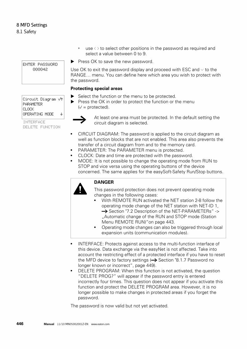
8 MFD Settings
8.1 Safety
446 Manual 11/10 MN05002001Z-EN www.eaton.com
• use ú í to select other positions in the password as required and select a value between 0 to 9.
Press OK to save the new password.
Use OK to exit the password display and proceed with ESC and Ú to the RANGE… menu. You can define here which area you wish to protect with the password.
Protecting special areas
Select the function or the menu to be protected. Press the OK in order to protect the function or the menu
(å = protected).
• CIRCUIT DIAGRAM: The password is applied to the circuit diagram as well as function blocks that are not enabled. This area also prevents the transfer of a circuit diagram from and to the memory card.
• PARAMETER: The PARAMETER menu is protected.• CLOCK: Date and time are protected with the password.• MODE: It is not possible to change the operating mode from RUN to
STOP and vice versa using the operating buttons of the device concerned. The same applies for the easySoft-Safety Run/Stop buttons.
• INTERFACE: Protects against access to the multi-function interface of this device. Data exchange via the easyNet is not affected. Take into account the restricting effect of a protected interface if you have to reset the MFD device to factory settings (→ Section "8.1.7 Password no longer known or incorrect“, page 449).
• DELETE PROGRAM: When this function is not activated, the question “DELETE PROG?” will appear if the password entry is entered incorrectly four times. This question does not appear if you activate this function and protect the DELETE PROGRAM area. However, it is no longer possible to make changes in protected areas if you forget the password.
The password is now valid but not yet activated.
ENTER PASSWORD
000042
Circuit Diagram åÆPARAMETER
CLOCK
OPERATING MODE æINTERFACE
DELETE FUNCTION
→ At least one area must be protected. In the default setting the circuit diagram is selected.
DANGER
This password protection does not prevent operating mode changes in the following cases:• With REMOTE RUN activated the NET station 2-8 follow the
operating mode change of the NET station with NET-ID 1, → Section "7.2 Description of the NET-PARAMETERs“ -> „Automatic change of the RUN and STOP mode (Station Menu REMOTE RUN)“on page 443.
• Operating mode changes can also be triggered through local expansion units (communication modules).

8 MFD Settings
8.1 Safety
Manual 11/10 MN05002001Z-EN www.eaton.com 447
8.1.3 Activating PasswordsAn already entered password can be activated in four ways in order to activate password protection:
• via the password menu (see below)• automatically when the device is switched on again.• automatically after a protected circuit diagram is loaded.• automatically if 30 minutes after unlocking
• a telegram is not sent from easySoft-Safety via the multi-function interface.
• a pushbutton is not actuated.
Activating password via the password menu
In the system menu enter the ACTIVATE PW menu via SAFETY -> PASSWORD.
The device shows this password menu only if a password is present.
Then press the OK button.
If you have deactivated a password beforehand, select ACTIVATE PW in the system menu and press OK.
The password is now active, i.e. password protection is activated.
You must unlock the device with the password before you implement a protected function, enter a protected menu or the System menu.
CHANGE PW
ACTIVATE PW
→ Make a notes of the password before activating it. If the password is no longer known, the device can be unlocked if the DELETE PROG area was not activated. However, the circuit diagram and data settings will be lost.
CAUTION
The following applies if the password is not known or is lost and the Delete password function is disabled: The device can only be reset to the factory setting at the manufacturers. The program and all data will be lost.

8 MFD Settings
8.1 Safety
448 Manual 11/10 MN05002001Z-EN www.eaton.com
8.1.4 Unlocking MFD Unlocking MFD deactivates password protection. You can then activate password protection later via the Password menu or by switching the supply voltage off and on.
The procedure to unlock the configuration or parts of it is always the same.
Press OK to enter the main menu. The PASSWORD… menu item will flash.
Press OK to enter the password entry menu.
The MFD device shows the password entry field.
Set the password using the cursor buttons. Confirm with OK.
The MFD device will automatically return to the status display if the password is entered correctly.
The PROGRAM menu option is now accessible so that you can edit your circuit diagram.
The System menu is also accessible.
8.1.5 Changing passwords Unlock the MFD device as previously described. Press DEL and ALT to call up the System menu. Open the password menu via SECURITY... -> PASSWORD…->CHANGE
PW.
The CHANGE PW entry flashes.
The MFD device only shows this menu if a password is already assigned.
Press OK to enter the password entry menu. Press OK to move to the 6-digit entry field.
The current password will be displayed.
→ The function of an area is accessible if a password is entered to unlock an area. All other functions protected by this password are now also unlocked.
PASSWORD...
STOP RUN åPARAMETER
SET CLOCK... → If MFD shows the PROGRAM main menu instead of PASSWORD, this means that no password protection is active.
ENTER PASSWORD
XXXXXX
PROGRAM...
STOP
PARAMETER
SET CLOCK...
CHANGE PW
ACTIVATE PW
PASSWORD ENTRY:
XXXXXX

8 MFD Settings
8.1 Safety
Manual 11/10 MN05002001Z-EN www.eaton.com 449
Modify the six password digits using the cursor buttons. Confirm with OK.
Use ESC to close the entry screen.
8.1.6 Delete password Press DEL and ALT to call up the System menu. Open the password menu via SECURITY... -> PASSWORD…->CHANGE
PW.
If a password is not entered, the MFD device shows six dashes. An existing password is displayed with XXXXXX.
Use number combination 000000 to delete a password.
8.1.7 Password no longer known or incorrectIf you no longer know the exact password, you can try to re-enter the password several times. If the DELETE PROG function is activated in the AREAS menu, the password can be entered as often as required.
Have you entered an incorrect password?
Re-enter the password.
After the fifth entry attempt MFD device will ask whether you wish to delete the circuit diagram and data.
Press• ESC: Circuit diagram, data or password are not deleted.• OK: Circuit diagram, data and password are deleted.
easy will return to the Status display.
Pressing ESC will retain the circuit diagram and data. You can then make another five attempts to enter the password.
ENTER PASSWORD
100005
ENTER PASSWORD
------
→ Assumption: The DELETE PROG area was not selected, → Section " Protecting special areas“, page 446.
PASSWORD ENTRY:
XXXXXX
DELETE ALL?
→ If you no longer know the exact password, you can press OK to unlock the protected easy. The saved circuit diagram and all function relay parameters will be lost.

8 MFD Settings
8.2 System
450 Manual 11/10 MN05002001Z-EN www.eaton.com
8.2 System
8.2.1 Switching on the input delay function (Debounce menu)The MFD device is factory set to evaluate input signals with an input delay, the so-called DEBOUNCE function. This ensures that any contact bouncing of switches and pushbuttons is masked out.
The input delay is set in the System menu.
However, for many applications, it is necessary to evaluate very short input signals. In this case, the debounce function can be switched off.
Press DEL and ALT to call up the System menu. Move to the menu SYSTEM and then to the DEBOUNCE menu.
8.2.1.1 Activating DEBOUNCE To activate DEBOUNCE, choose DEBOUNCE and press OK. The debounce is activated and the display changes to DEBOUNCE å.
Press ESC to return to the previous menu.
8.2.1.2 Deactivating DEBOUNCEIf the menu displays DEBOUNCE å (with a tick), this means that the debounce function is already activated.
To deactivate DEBOUNCE, choose DEBOUNCE å and press OK. Debounce mode will be deactivated and the display will show DEBOUNCE without a tick.
→ If the MFD device is protected with an STD PASSWORD, you must remove password protection before you can call the system menu.
DEBOUNCE åÆP PUSHBUTTONS
RUN MODE
CARD MODE æ
→ How MFD input signals are processed internally, → Section "9.2.1 Input delay (debounce)“, page 474.

8 MFD Settings
8.2 System
Manual 11/10 MN05002001Z-EN www.eaton.com 451
8.2.2 P PUSHBUTTONSEven though the cursor buttons (P buttons) have been set as contacts in the circuit diagram, these are not activated automatically. In order to prevent accidental actuation, the cursor buttons cannot switch until they have been activated.
The other operator buttons on the MFD-CP10... can also be used as additional contacts.
Activate the P buttons in the System menu.
The P pushbuttons are activated and deactivated via the P BUTTONS menu.
Press DEL and ALT to call up the System menu. Select the SYSTEM menu. Move the cursor to the P BUTTONS menu.
8.2.2.1 Activating P pushbuttonsIf is displaying MFD P PUSHBUTTONS å, this means that the P pushbuttons are active.
Otherwise select P PUSHBUTTONS and press OK.
The MFD device chances the display to P BUTTONS å indicating that the P buttons are activated.
Press ESC to return to the status display.
8.2.2.2 Deactivating the P pushbuttons Select P PUSHBUTTONS å and press OK.
The tick behind P PUSHBUTTONS disappears and the P pushbuttons are deactivated.
→ If MFD is protected with a password, you must remove password protection before you can call the system menu.
DEBOUNCEå ÆP PUSHBUTTONS
RUN MODE
CARD MODE æ
DEBOUNCE åÆP BUTTONS åRUN MODE
CARD MODE æ
→ The P pushbuttons are only active in the status display and the text display. In this display you can use the P buttons to activate inputs in your circuit diagram.
→ The P buttons are automatically deactivated if you load a circuit diagram from the memory card or via easySoft-Pro onto the MFD device or if you are deleting a circuit diagram in the MFD device.

8 MFD Settings
8.2 System
452 Manual 11/10 MN05002001Z-EN www.eaton.com
8.2.3 Setting the startup behaviorThe startup behavior is an important aid during the commissioning phase. The circuit diagram which MFD contains is not as yet fully wired up or the system or machine is in a state which MFD is not permitted to control. If MFD device is then switched on, it should not be possible to activate the outputs.
Set the Startup behavior in the system menu.
Switch to the system menu.
Set whether the MFD device is to switch to RUN mode or not when the supply voltage is switched on.
The MFD devices without a display start up automatically when RUN MODE is active.
8.2.3.1 RUN MODE Activating RUN mode
If the MFD device shows RUN MODE å , the device will start in RUN mode when the supply voltage is switched on. However, if there is no circuit diagram in the device, it will stay in STOP operating mode until a circuit diagram is entered or downloaded.
Otherwise select RUN MODE and press OK.RUN mode is activated.
Press ESC to return to the status display.
Deactivating RUN mode
Select RUN MODE å and press OK.
The RUN mode function is deactivated.
The MFD device is factory set with RUN MODE å displayed, i.e. the device starts in RUN operating mode when the voltage supply is switched on.
→ The MFD devices without a display can only be switched to RUN MODE without the programming software by activating RUN MODE as startup behavior. This change is possible if the MFD device contains a valid circuit diagram.
→ If the MFD device is password protected, the System menu is only accessible after the device has been unlocked (→ Section "8.1.4 Unlocking MFD“, from page 448).
DEBOUNCEå ÆP PUSHBUTTONS
RUN MODE åCARD MODE æ
DEBOUNCEå ÆP PUSHBUTTONS
RUN MODE
CARD MODE æ

8 MFD Settings
8.2 System
Manual 11/10 MN05002001Z-EN www.eaton.com 453
Behavior on deleting the circuit diagram
The setting for the startup behavior is an MFD device function. When the circuit diagram is deleted this does not result in the loss of the setting selected.
Behaviour during upload/download to card or PC
The setting is retained if a valid circuit diagram is transferred from MFD device to a memory card or PC. This also applies in the opposite direction, i.e. from the memory card or PC to the MFD.
Possible Faults
MFD device will not start in RUN mode:
• A program is not available in MFD device.• You have put MFD in STOP mode (RUN MODE menu).
8.2.3.2 CARD MODEThe Card mode startup is designed for applications in which a program change can even by carried out by unskilled personnel by simply exchanging the memory card.
If the program on the memory card is different to the program in the MFD device, the program from the card will be loaded on power up first of all and then started in RUN mode. If the programs only contain different function block setpoints (constants), the program on the memory card is not loaded. The program is retained in the device and is started.
Factory setting: CARD MODE inactive
Switch to the system menu.
Menu displayed
Status of MFD after startup
RUN MODE MFD is in STOP mode
RUN MODEå MFD switches to RUN mode
→ The MFD devices without a display can only be started in RUN mode.
→ Card mode functions:on the MFD-CP8... only with the EASY-M-256K memory card. on the MFD-CP10... only with the EASY-M-512K.
→ If the MFD device is password protected, the System menu is only accessible after the MFD device has been unlocked (→ Section "8.1.4 Unlocking MFD“, from page 448).

8 MFD Settings
8.2 System
454 Manual 11/10 MN05002001Z-EN www.eaton.com
Activation of CARD MODE
Otherwise choose CARD MODE and press OK.
The MFD device now displays CARD MODE å.
Return to the status display using ESC.
Deactivating CARD MODE
Select CARD MODE å and press OK.The CARD MODE function is deactivated.
8.2.4 TERMINAL MODE startup (TERMINAL MODE menu item)The startup behavior of an MFD with automatic start in Terminal mode is designed for applications in which other devices are remotely controlled by the MFD, → Section "3.9 Running MFD in Terminal mode“, page 136, .
In the SYSTEM menu you set the MFD to switch to TERMINAL MODE when the voltage supply is switched on and establish a connection to the defined station. The setting of the connection to the required station, → Section "3.9 Running MFD in Terminal mode“, page 136.
8.2.4.1 Activating an automatic startup in TERMINAL MODETerminal mode is deactivated in the factory setting.
Press DEL and ALT simultaneously to switch from the Status display to the System menu.
DEBOUNCE åÆP PUSHBUTTONS
RUN MODE åCARD MODE åæ
→ If CARD MODE is activated:
• A MFD device only switches to RUN mode on power up if a memory card with a valid program is fitted.
• An MFD device cannot be switched to RUN mode on power up if the program in the MFD device is different to the program on the memory card. First the modified program must be transferred to the card or CARD MODE must be deactivated.
DEBOUNCEå ÆP PUSHBUTTONS
RUN MODE åCARD MODE æ
→ If the MFD is password-protected, the System menu can only be accessed after the device has first been “unlocked” (→ Section "8.1.4 Unlocking MFD“, from page 448).

8 MFD Settings
8.2 System
Manual 11/10 MN05002001Z-EN www.eaton.com 455
Choose TERMINAL MODE and system menu and press OK.
At the next startup, the MFD device will establish a connection to the set station.
Press ESC twice to return to the Status display.
8.2.4.2 Deactivating automatic startup in TERMINAL MODE Select TERMINAL MODE å in the System menu and press OK again.
The automatic starting in TERMINAL MODE has been deactivated.
Press ESC twice to return to the Status display.
8.2.5 Activating external buttons (I-BUTTONS and R-BUTTONS menu items)The I pushbuttons and R pushbuttons options enable the operator to operate a MFD in a harsh environment by means of external function keys such as RMQ control circuit devices.
External pushbuttons that are connected to the local I input terminals or the R input terminals of the expansion unit can thus take on the same functions as the operator buttons of the device. The I or R input terminals are permanently assigned to the function keys.
P PUSHBUTTONS ÆRUN MODE
CARD MODE
TERMINAL MODE åæ
P PUSHBUTTONS ÆRUN MODE
CARD MODE
TERMINAL MODE æ
→ You can only activate one of the two I or R button options. Inputs that are activated as operating buttons are no longer available for control tasks in the circuit diagram.

8 MFD Settings
8.2 System
456 Manual 11/10 MN05002001Z-EN www.eaton.com
Table 43: Assigning Operator Buttons and I or R Input Terminals
The operator can produce the same effect as pressing the operator buttons (e.g. DEL+ALT) by pressing two buttons (e.g. I7+I8) simultaneously.
External pushbuttons and operator buttons of the device are evaluated at the same time thus enabling mixed operation.
In exceptional cases when the external pushbutton and the assigned operator button of the device are pressed simultaneously, the actuation of the external pushbutton is ignored. This excludes the possibility of contradictory operating states.
If an external pushbutton and an function key with different functions are pressed simultaneously, this is interpreted by the device as a button combination.
R PUSHBUTTONS
See the identical function description of the I buttons.
8.2.6 Setting contrast and backlight (DISPLAY menu item)The backlight of the LCD display can be adjusted to one of 5 levels in order to suit local conditions.
Using the Display backlight button element enables the operator to change the backlight level during operation by pressing a button (→ Section "6.6.3 Display Backlight“, from page 419). The backlight can also be changed in the program via the LE1 output operand.
The contrast of the display can be set to one of 17 stages.
When using an MFD-CP10… the use of the Display contrast button element enables the operator to change the contrast during operation via an operator button (→ Section "6.6.4 Display contrast“, from page 420).
Operator Button I-Input terminal R-Input terminal
Cursor left I1 R1
Cursor up I2 R2
Cursor right I3 R3
Cursor down I4 R4
OK I5 R5
ESC I6 R6
DEL I7 R7
ALT I8 R8
* pushbutton (can only be assigned on a visualization device). I9 on the 800 control relay can be used for control tasks.
I9 R9

8 MFD Settings
8.2 System
Manual 11/10 MN05002001Z-EN www.eaton.com 457
The contrast and backlight settings are device settings.
Switch to the system menu.
In the system menu choose SYSTEM -> System-> DISPLAY and press OK.
The menus for setting the contrast and backlight are displayed.
Press the OK pushbutton and change the contrast setting.
Use the cursor buttons Í and Ú to set a contrast between –8 and +8 and press OK pushbutton to confirm the setting.
The contrast setting is valid until it is changed again.
Use the cursor buttons Í and Ú to move to the LIGHTING menu. Press OK.
Use cursor buttons Í and Ú to change the value in 25 % steps. Set the required backlighting.
→ If the MFD device is password protected, the System menu is only accessible after the MFD device has been unlocked (→ Section "8.1.4 Unlocking MFD“, from page 448).
CONTRAST: 0
LIGHTING: 75%
CONTRAST: +1
LIGHTING 75%
CONTRAST: +1
LIGHTING 75%
CONTRAST: +1
LIGHTING 75 %
→ The backlight changes immediately when the value is set. 0, 25, 50, 75 and 100% are possible values.
CONTRAST: +1
LIGHTING 100% → MFD device comes with the following factory setting:• The contrast is set to 0.• The backlight is permanently activated. Menu setting:
LIGHTING å. The backlight is set to 75%.
→ MFD device comes with the following factory setting:• The contrast is set to 0.• The backlight is set to 75%.

8 MFD Settings
8.2 System
458 Manual 11/10 MN05002001Z-EN www.eaton.com
8.2.7 Storing data retentively (Retention menu item...)Plant and machine controls require the possibility to retentively set operating states or actual values, i.e. the values should be retained safely even after the supply voltage of a machine or plant has been switched off and should be left unchanged until the actual value is overwritten.
The following operands and function blocks can be set to operate retentively:
• Markers.• Counter function blocks.• Data function block.• Timing relays.
Hour meter
An MFD device is provided with 4 operating hours counters. These are always retentive and can be deleted specifically using a Reset command. Operating hours counters do not reduce the memory available for retentive data.
Memory for retentive data
The following table shows the maximum available memory for retentive data in the RAM.
Markers
The following table shows the maximum number of marker bytes that can be declared as retentive, with the limitation defined by the memory sizes stated above. The structure of the entire memory range is shown in → Table 25, page 154.
Counter
All C.., CH.. and CI.. function blocks can be operated with retentive actual values.
Data Function Blocks
A user-definable consistent function block DB.. range can be operated with retentive actual values.
Device The maximum retentive memory [Byte]
MFD-CP8… 200
MFD-CP10… 400
Device Possible retentive marker bytes
MFD-CP8… MB 01-MB96
MFD-CP10… MB 01-MB192

8 MFD Settings
8.2 System
Manual 11/10 MN05002001Z-EN www.eaton.com 459
Timing Relay
A user-definable and contiguous range for timing relays T.. can be run with retentive actual values.
Requirements:In order to make data retentive, the relevant markers and function blocks must have been declared as retentive.
8.2.7.1 Setting retentive behaviorRequirement:The MFD device must be in STOP mode.
Press DEL and ALT simultaneously to switch from the Status display to the System menu.
The devices are factory set with no retentive actual value data selected. All actual values are therefore deleted if the MFD device is switched to STOP mode or de-energized.
Switch to STOP mode. Switch to the system menu. Enter the system menu via STD PARAMETERS and then on to the
RETENTION… menu. Press the OK button.
The first screen that appears is a selection dialog for operand marker bytes (MB). The display on the lower right B:200 indicates the number of free bytes. Use ÍÚ to select the operand. Press OK to access the Entry modes.
• ú í Select position from to.• ÍÚ Set a value.
If necessary select the next operand.
In all, six different operand ranges can be selected.
Example: MB 01 to MB 04, C 12 to C 16, DB 01 to DB 16, T 08 to T 14 should be retentive.
CAUTION
The retentive data is stored every time the power supply is switched off and read when the supply voltage is switched on. The data integrity of the memory is guaranteed for 1010 write-read cycles.
→ If the MFD device is password protected, the System menu is only accessible after the MFD device has been unlocked (→ Section "8.1.4 Unlocking MFD“, page 448).
RUN MODE å ÆDEBOUNCE..
DISPLAY...RETENTION... æ
MB 00 -> MB 00 ÆC 00 -> C 00
DB 00 -> DB 00 æ B:200
MB 01 -> MB 04
C 12 -> C 16
DB 01 -> DB 16
B:076
RETAIN MARKERS
T 08 -> T 14

8 MFD Settings
8.2 System
460 Manual 11/10 MN05002001Z-EN www.eaton.com
124 bytes have been assigned to the retentive data range. 76 bytes are still available.
Select the RETAIN MARKERS option if you wish to retain the retentive actual values when transferring the circuit diagram from easySoft-Pro or the memory card to the MFD device.
Alternatively you can select the Retain markers during transfer option in easySoft-Pro.
Save the entry from .. to .. with OK.
Press ESC to exit the input for the retentive ranges.
8.2.7.2 Deleting areasSet the ranges to be erased to the values from 00 to 00.
e.g.: MB 00 -> MB 00. The markers are no longer retentive.
Deleting retentive actual values of markers and function blocks
The retentive actual values are cleared if the following is fulfilled (applies only in STOP mode):
• When the circuit diagram is transferred from easySoft-Pro (PC) or from the memory card to the MFD device, the retentive actual values are reset to 0. This does not occur if you have selected the Retain markers during transfer option in easySoft-Pro or activated the RETAIN MARKERS option on the device.
• When changing the respective retentive range.• When the circuit diagram is deleted via the DELETE PROG menu.
8.2.7.3 Transferring retentive behaviorThe retention setting is a circuit diagram setting and is carried with the program when it is transferred from the memory card or from easySoft-Pro.
8.2.7.4 Changing the operating mode or the circuit diagramWhen the operating mode is changed or the MFD circuit diagram is modified, the retentive data is normally saved together with their actual values. The actual values of relays no longer being used are also retained.
8.2.7.5 Changing the operating modeIf you change from RUN to STOP and then back to RUN, the actual values of the retentive data will be retained.

8 MFD Settings
8.3 Menu language
Manual 11/10 MN05002001Z-EN www.eaton.com 461
8.2.7.6 Changing the MFD circuit diagramThe actual values are retained if the MFD circuit diagram is changed.
8.2.7.7 Changing the startup behavior in the SYSTEM menuThe retentive actual values are retained in MFD device regardless of the setting.
8.2.7.8 Modification of the retentive rangeIf the set retentive ranges are reduced, only the actual values saved in the range will remain.
If the retentive range is extended, the older data is retained. The new data is written with the current actual values in RUN mode.
8.3 Menu languageThe MFD device provides 13 different menu languages:
8.3.1 Changing the menu languageYou can change the menu language in the System menu.
Language Display
English ENGLISH
Deutsch DEUTSCH
French FRANÇAIS
Spanish ESPAŇOL
Italian ITALIANO
Portuguese PORTUGUÊS
Dutch NEDERLANDS
Swedish SVENSKA
Polish POLSKI
Turkish TÜRKÇE
Hungarian MAGYAR
Czech ĆESKY
Russian РУССКИЙ
→ Language selection is only possible if the MFD device is not password-protected.

8 MFD Settings
8.4 Configurator
462 Manual 11/10 MN05002001Z-EN www.eaton.com
Press DEL and ALT to call up the System menu. Select here the MENU LANGUAGE… for changing the language.
The language selection for the first entry ENGLISH is displayed.
Use Í or Ú to select the new menu language, e.g. French FRANÇAIS. Confirm with OK. FRANÇAIS is provided with a tick. Exit the menu with ESC.
MFD device will now show the new menu language.
Press ESC to return to the Status display.
The menu language setting is a device function. This means that when the circuit diagram is deleted this does not result in the loss of the setting selected.
8.4 ConfiguratorCall the configurator in the System menu. The following menu items vary according to the device or the connected periphery.
8.4.1 NETA description of how to parameterize and configure the easyNet network is provided in, → section “3.7 Commissioning NET stations”, page 122.
8.4.2 COMA description of how to parameterize and activate a COM-LINK, i.e. the point-to-point connection between an MFD and another device → Section "3.8.2.2 activate COM-LINK“, page 134.
8.4.3 LINKIn this menu you assign parameters to a configurable local expansion unit that is connected to the easyLink terminal of the basic device. The menu is only accessible if this type of local expansion unit is connected.
ENGLISH
DEUTSCH
FRANÇAIS
ESPAŇOL æITALIANO
PORTUGUÊS
NEDERLANDS
SVENSKA
POLSKI
TÜRKÇE
MAGYAR
ĆESKY
РУССКИЙ
SECURITE...
SYSTEMS...
LANGUE MENUS...
CONFIGURATEUR...

8 MFD Settings
8.4 Configurator
Manual 11/10 MN05002001Z-EN www.eaton.com 463
The configurable expansion units include the communication expansion units such as EASY 204-DP and the EASY4..-DC-ME analog expansion units.
8.4.4 Configuring analog expansion unitsHow to configure analog expansion devices, → Section "3.6 Configuring the analog expansion unit“, page 117.
8.4.5 Configure communication expansion unitWith a communication expansion unit you only configure the address via which it is to be accessed on the fieldbus. The AWA2528-.... for the expansion unit provides the relevant information.
8.4.6 ETHERNET-GWThis menu is used to assign parameters for an EASY209-SE Ethernet gateway that is connected to the serial multi-function interface.
Basic requirements:
• The easy800 or MFD device must be in STOP operating mode.• The device and the Ethernet gateway must be interconnected via an
EASY800-MO-CAB or MFD-CP4-500-CAB5 connection cable.
The following table shows the available parameters and their factory settings for an Ethernet coupling unit.
The description of the parameters is provided in the operating manual for the Ethernet gateway AWB2528-1596., chapter Configuration via the RS232 interface and in the Help system of easySoft-Pro.
Table 44: Factory settings for an Ethernet coupling unit on easy800 or MFD
8.4.7 IO MODULESThis menu is used to set the temperature module of the MFD which is fitted on the power supply unit/CPU module. Further information on this → Section "3.5 I/O module with temperature measuring“, page 107.
→ An EASY209-SE Ethernet gateway can be run on a basic device from device version 08.
IP ADDRESS 0000.000.000.000
SUBNET-MASK 0000.000.000.000
GATEWAY-ADDRESS 0000.000.000.000 (standard gateway)
REMOTE-ADDRESS 0000.000.000.000
PORT-NUMBER 10001
REMOTE-PORT 00000
BAUD RATE 9600

8 MFD Settings
8.5 Setting time
464 Manual 11/10 MN05002001Z-EN www.eaton.com
8.5 Setting timeThe MFD feature a real-time clock with date and time functionality. This allows the use of the time switch function blocks for implementing time switch functions.
8.5.1 Setting time and dateIf the clock is not set or MFD device is switched on after the battery back-up time has elapsed, the clock starts with the setting WE 1:00 05/01/2002. The MFD clock operates with date and time so that hour, minute, day, month and year have to be set.
Select SET CLOCK… from the main menu.This will open the menu for setting the time.
Choose SET CLOCK here.
Set the values for time, day, month and year. Press OK pushbutton to activate Entry mode:
• ú í Select the position.• ÍÚ Change the value of a parameter• OK: Save day and time• ESC: Retain previous setting.
Press ESC to leave the time setting display.
8.5.2 Summer/winter timeThe MFD devices are fitted with a real-time clock. These devices can be automatically switched between summer and winter time. These are subject to different legal requirements in the EU, GB and USA.
8.5.2.1 General
The following options are available for setting DST parameters:
• NONE: No DST setting.• MANUAL: User-defined daylight saving time setting.• EU: Date for European Union; Start: Last Sunday in March; End: Last
Sunday in October.
SET CLOCK
SUMMER TIME
HH:MM: 00:27
DD.MM: 05.05
YEAR : 2010
→ The DST setting you have defined is always linked with the program. When commissioning systems controlled by MFD for worldwide use it may be necessary to set and store this program also with the regional DST setting.For these kinds of MFD devices for worldwide use, use the “Rule” option for a DST setting.

8 MFD Settings
8.5 Setting time
Manual 11/10 MN05002001Z-EN www.eaton.com 465
• GB: Select these options when using an MFD-CP10.... Start: Last Sunday in March; End Last Sunday in October.When using an MFD-CP8..., select the EU option for the legally applicable time change for the United Kingdom since the GB option for this device stores the now obsolete rule. This is as follows: Start: Last Sunday in March; End: Fourth Sunday in October. After the statutory settings have changed, the above rules for the European Union will also apply to the United Kingdom.
• US: Select these options when using an MFD-CP10.... When using an MFD-CP8..., set the Start and end of the DST time via the Rule… menu item or select the New Northern America DST rule supplied in easySoft for the currently applicable time change. This rule is as follows:Start - Second Sunday in March at 2:00 a.m. local time; End - First Sunday in November at 2:00 a.m. local time.On an MFD-CP8... the US option stores the following date according to the now obsolete rule: Start: First Sunday in April; End: Last Sunday in October
• RULE: User-defined dates and changeover times as well as time difference selectable between 0 and 3 hrs; can be set in stages of 0.5 hrs.
8.5.2.2 Setting DST parametersSelect SET CLOCK… from the main menu and press OK.
This will open the menu for setting the time.
Select the DST menu and press OK.
The time change option is shown in the next menu.
Selecting the DST setting option
The standard setting is NONE for automatic DST changeover (å at NONE).
Select the required option for the DST setting and press OK.
SET CLOCK
SUMMER TIME
US
RULE
NONE å ÆMANUAL
EU
GB æ

8 MFD Settings
8.5 Setting time
466 Manual 11/10 MN05002001Z-EN www.eaton.com
Manual option
To set your own date.
Change to the MANUAL menu and press OK 2 x.• Select the position with ú í.• Change the value with ÍÚ.• Press OK to save day and time or press ESC to restore the previous
setting.
Press ESC to leave the display. Select the day and the month on which the summer time is to start. Select the day and the month on which the summer time is to end.
On the MFD-CP8... the time change always takes place in the subsequent years on the selected days, for example on each Sunday.
On the MFD-CP10... the time change always takes place in the subsequent years on the selected date, for example on the 30th of the month.
“EU”, “GB” or “US” options
Move to one of the EU, GB or US menus and press OK. Exit the menu with ESC.
The time setting is active and the MFD device switches to the following times according to these regional presets:
The following applies to the winter → summer time change with the regional presets EU, GB or US: On the changeover day the clock will switch from 2:00 to 3:00.
The following applies to the summer → winter time change with the regional presets EU, GB or US: On the changeover day the clock will switch back from 3:00 to 2:00.
Rule option
Change to the RULE menu and press OK. Choose SUMMERTIME START and press the OK button.
The flashing cursor is located in line 1, column 1 on the word ON.
SUMMERTIME START
DD.MM: 01.01
SUMMERTIME END
DD.MM: 01:01
→ The same time for conversion applies as for the legally specified variants (EU, GB, US).
→ If you create a rule in the rule editor of the easySoft-Pro, you can access the national time scenarios provided on a row. These include possible worldwide time scenarios both for the northern and for the southern hemisphere. In special cases you can create your own special rules based on these.
SUMMERTIME START
SUMMERTIME END

8 MFD Settings
8.5 Setting time
Manual 11/10 MN05002001Z-EN www.eaton.com 467
Press OK gain to move to Entry mode in order to set the changeover day parameters for summer time.
Use cursor buttons Í or Ú to set day 1 to 4 or the last day and press OK. Position the cursor in succession with the ú í or ÍÚ buttons at the
required entry locations and change the Weekday parameter (SO), Month (OF xx. Month), Time (AT xx:xx) or the time difference (DIFF:) as previously described for the changeover day.
Press ESC to exit the SUMMER TIME START and choose SUMMER TIME END.
Set the changeover data to winter time as previously described for the changeover day to summer time and exit the menu with ESC.
The time difference (DIFF:) parameter corresponds to the entry for the changeover day to summer time and cannot be changed in this menu. The MFD device now alternates between summer and winter time according to your rule.
ON LAST SU
OF MONTH 03
AT 02:00
DIFF: + 1:00

8 MFD Settings
8.5 Setting time
468 Manual 11/10 MN05002001Z-EN www.eaton.com

9 Inside MFD
9.1 MFD Program
Manual 11/10 MN05002001Z-EN www.eaton.com 469
9 Inside MFD
9.1 MFD ProgramIn conventional control systems, a relay or contactor control processes all the rungs in parallel. The speed with which a contactor switches is thus dependent on the components used, and ranges from 15 to 40 ms for relay pick-up and drop-out.
With MFD the circuit diagram is processed with a microprocessor that simulates the contacts and relays of the circuit concerned and thus processes all switching operations considerably faster. Depending on its size, the circuit diagram is processed cyclically every 0.1 to 40 ms. During this time, the MFD device passes through six segments in succession.
If the operands of the inputs and outputs are addressed in the MFD, the signal states of the digital inputs/outputs are not scanned but a memory range in the device system memory is accessed. This memory range is called the process image. The process image is divided into two sections: the process image for the inputs and the process image for the outputs.
9.1.1 How the MFD device evaluates circuit diagrams and function blocks
9.1.1.1 Segment 1 - 4The MFD device evaluates the contact fields within the first four segments. The evaluation starts in the first segment in circuit diagram line 1 and continues from top to bottom until circuit diagram line n is reached. The MFD device then moves to the next contact segment and continues to evaluate from top to bottom until it has reached the last contact in the fourth segment. During this process it checks whether contacts are switched in parallel or in series and saves the switching states of all contact fields.
Rung Segment
1 2 3 4 5 6
1 2 3 4
.. … I 12----------------------------Ä Q 08
I 01----I 04----HW01Q1--T 06Q1-Ä T 01EN I 02----I 03-------------------R Q 02
T 01---u-----------------------Ä Q 01 P 01---k

9 Inside MFD
9.1 MFD Program
470 Manual 11/10 MN05002001Z-EN www.eaton.com
9.1.1.2 Segment 5In the fifth segment the MFD device assigns all coils in one pass, from the circuit diagram line 1 - n, with the new switch states from the process image of the outputs.
9.1.1.3 Segment 6In the sixth segment which is outside of the circuit diagram, the function blocks present in the function block list are evaluated.
The MFD device uses this sixth segment in order to:
• process the existing function blocks.The output data of a function block is immediately up-to-date after it has been processed. The function blocks are processed by the MFD device in the order of the function block list (→ FUNCTION BLOCKS menu).
The following requirements must be fulfilled when using particular function blocks (→ section “9.1.4 Allowing for the special feature of certain function blocks”, page 472).
• Contact the “outside world”: Output relays Q 01 to Q… are switched and inputs I 1 to I… are re-read. For the expansion modules the S... output relays are switched and the R... inputs are read accordingly.
• to exchange easyNet data if this MFD device receives new read data or provides new send data (→ Section "7 The network Net“ on page 469).
• to copy all new switch states to the status image.
The MFD device uses a fixed status image register that lasts for the duration of a cycle. This ensures that each rung is evaluated with the same switching states for one cycle, even if the input signals at I1 to I12, for example, change their status several times within a cycle.
9.1.2 Cycle-time monitoringThe device monitors the time required for a cycle to be completed.
If a fault causes the cycle time to exceed 1.05 s, the device switches the Q .. output relays to the safe state 0.

9 Inside MFD
9.1 MFD Program
Manual 11/10 MN05002001Z-EN www.eaton.com 471
9.1.3 What you must consider when creating the circuit diagramThe MFD device evaluates the circuit diagram in segments, and from top to bottom within a segment, from circuit diagram line 1 - n. You should therefore remember two points when you create your circuit diagrams:
• The changeover of a relay coil does not change the switching state of an associated contact until the next cycle starts.
• Always wire forward or from top to bottom. Never work backwards.
9.1.3.1 Example: Self-latching with own contactStart condition:Inputs I 01 and I 02 are switched on. Q 01 is switched off.
This is the circuit diagram of a self-latching circuit. If I 01 and I 02 are closed, the switching state of relay coil Ä Q 01 is “latched” via contact Q 01.
1st cycle: Inputs I 01 and I 02 are switched on. Coil Q 01 picks up.
Switching contact Q 01 remains off because the MFD device processes the circuit diagram segment for segment from top to bottom and from left to right from the first segment. By the time the MFD device refreshes the process image of the outputs and therefore the coil field with Q 01 in the fifth segment, contact field Q 01 in the second line of the circuit diagram has already been processed.
2nd cycle: The self-latching only now becomes active. The MFD device has transferred the coil states at the end of the first cycle to contact Q 01.
9.1.3.2 Example: Do not wire backwardsThe following circuit diagram shows an example of why you should not wire backwards. In the third rung, the MFD device finds a connection to the second rung in which the first contact field is empty. The output relay is therefore not switched.
Figure 267: Circuit diagram with five contacts, invalid
Figure 268: Circuit diagram with M 01 marker relay
I 01--u-I 02-..--Ä Q 01Q 01--k
→ Use one of the 96 auxiliary relays M.., if you have to connect more than four contacts in series.
I 01----Q 04----I 03--o z---------------k h-I 02----I 04-----------Ä Q 02
I 01----Q 04----I 03----I 05---Ä M 01I 02----I 04----M 01-----------Ä Q 02

9 Inside MFD
9.1 MFD Program
472 Manual 11/10 MN05002001Z-EN www.eaton.com
9.1.4 Allowing for the special feature of certain function blocks
9.1.4.1 How the MFD device evaluates the high-speed counters CF, CH and CIIn order to evaluate the count pulses of up to 3 kHz, the high-speed counter function blocks operate with an interrupt routine. The length of the circuit diagram and the associated cycle time has no effect on the counter result.
9.1.4.2 Operating a DC or FT function block
9.1.5 What affects the cycle time of an MFD deviceAs well as the processing time required for the circuit diagram rungs and the function blocks in use, the cycle time of an MFD can also be influenced by the following factors.
9.1.5.1 Data exchange via COM-LINKData exchange via the COM-LINK point-to-point connection is possible in any segment of the cycle. This data exchange increases the cycle time both on the active and on the remote station. Only use those COM-LINK operands that are required.
9.1.5.2 Loading visualization dataWhen setting a program to RUN operating mode that contains visualization data, the contents of the screens to be displayed have to be loaded.
The time required for loading in the event of a mask change depends on the size of the masks to be loaded. The loading time can be calculated as follows:Screen size in byte multiplied by 80 μs.
Example: Screen size 250 bytes:
The loading time for the screen is: 250 × 80 μs = 20 ms
→ The following has to be taken into account when operating a PID controller (DC) or a signal smoothing filter (FT):The cycle time of the program must be less than the scan time of these function blocks. If the cycle time is greater than the scan time, these function blocks cannot supply any constant results.
→ The following applies if a short cycle time is required on the MFD: Use several small screens so that the loading time when changing screens is not too long. Only use the screens with content that is really necessary (→ Section "6.4.1 Screen memory“ of page 370).

9 Inside MFD
9.1 MFD Program
Manual 11/10 MN05002001Z-EN www.eaton.com 473
The loading of screen data and screen changes can be implemented in any segment of the program cycle. Take this behavior into account when considering the reaction time of your entire control system.
9.1.6 MFD memory managementThe MFD is provided with a screen and program memory.
• Screen memory:• MFD-CP8..., 24 kByte • MFD-CP10..., 48 kByte
The screen memory stores the visualization data created with easySoft-Pro retentively.
• Program memory:• MFD-CP8..., 8 kByte • MFD-CP10..., 16 kByte
The program memory stores the program retentively.
9.1.6.1 Distribution of data in the program memoryMFD-CP8
During the runtime, the program memory stores the program, the retentive data and the screens to be displayed. The largest screen to be displayed reduces the memory available for the program.
→ Distribute the tasks between several devices, which exchange data between each other via easyNet. Use MFD devices for open and closed loop control and other MFD devices for display and operation.
→ The MFD-CP8 provides you with the largest possible memory for your program if you:• only select the required retentive data bytes,• create several smaller screens with fewer graphic elements
instead of one large screen with several graphic elements (for example message bitmaps and bitmaps),
• reduce the size and number of graphic elements to what is necessary.

9 Inside MFD
9.2 Time behavior of the inputs and outputs
474 Manual 11/10 MN05002001Z-EN www.eaton.com
Figure 269: Division of program and screen memory on the MFD-CP8...
MFD-CP10...
During the runtime the program memory stores the program and the retentive data. The screen size does not have any effect on the program size.
9.2 Time behavior of the inputs and outputsThe reaction time, which is measured from the reading in of a digital input signal to the setting of the associated output, is determined by the timing characteristics of the device inputs and outputs as well as the size and design of the circuit diagram.
9.2.1 Input delay (debounce)The time required from reading the inputs and outputs to switching the contacts in the circuit diagram can be increased on the MFD device using an input delay, the so-called DEBOUNCE, → Section "8.2.1 Switching on the input delay function (Debounce menu)“, page 450.
This function is useful, for example, in order to ensure a clean switching signal despite contact bounce.
→ The MFD-CP10... provides you with the largest possible memory for your program if you:• observe the instructions stated for the MFD-CP8.. and• only load the required download languages to the device.
MFD-CP8... program memory
Program
Screen 4
Screen 4
Screen 1
Screen 2
Screen 3
Screen 5
Screen memory
8 kB
24 k
B

9 Inside MFD
9.2 Time behavior of the inputs and outputs
Manual 11/10 MN05002001Z-EN www.eaton.com 475
Figure 270: MFDinput assigned a switch
MFD DC and MFD AC units function with different input voltages and therefore also have different evaluation methods and delay times.
9.2.2 Delay time with MFD DC basic devicesDelay time with DEBOUNCE activated
When DEBOUNCE is activated, the delay time for DC signals is 20 ms.
Figure 271: Delay times for evaluating an DC input signal and an activated DEBOUNCE
An input signal S1 must therefore be > 15 V on the input terminal for at least 20 ms before the switch contact will change from 0 to 1 (A). If applicable, this time must also include the cycle time (B) since a MFD device does not detect the signal until the start of a cycle.
When the DC voltage signal drops out from 1 to 0 and DEBOUNCE is active, the same delay time (C) of 20 ms is applied before the signal is transferred to the next circuit diagram cycle.
S1
0V I1
→ When using high-speed counter function blocks, the delay time for the input signals must not exceed 0.025 ms. DEBOUNCE must therefore be deactivated.
A C
1
0
1
0
S1
B BB B B
I1

9 Inside MFD
9.2 Time behavior of the inputs and outputs
476 Manual 11/10 MN05002001Z-EN www.eaton.com
Delay time with DEBOUNCE deactivated
When DEBOUNCED is deactivated, the typical delay time for DC signals on the input caused by the hardware lies between 0.025 ms and 0.25 ms (A). The cycle time (B) must be added as well before the signal is safely detected in the circuit diagram.
Figure 272: Switching behaviour with DEBOUNCE deactivated
Typical delay times with DEBOUNCE deactivated are:
• On-delay for:• I1 to I4: 0.025 ms• I5 to I12: 0.25 ms
• Off delay for:• I1 to I4: 0.025 ms• I5, I6 and I9 to I10: 0.4 ms• I7, I8, I11 and I12: 0.2 ms
9.2.3 Delay time with MFD AC basic devicesWith AC inputs the MFD device scans the input signal in long or short scan cycles tSC depending on whether DEBOUNCE is activated/deactivated. The scan cycle also depends on the frequency of the supply network.
Delay time with DEBOUNCE activated
If the DEBOUNCE function is activated, the MFD device checks whether a positive half-wave is present at an input terminal during two successive scan cycles tSC1 (1st and 2nd scan pulse at A). If the MFD device registers two positive half waves in succession, it switches the appropriate input (contact) internally from 0 to 1.
→ When DEBOUNCE is deactivated ensure that input signals are free of noise. The MFD device responds to very short signals.
→ In order for an input signal to be detected and processed reliably, it must be stable for a minimum period which depends on the processing time (cycle time) of the circuit diagram.
1
0
1
0
S1
BB BB B B
A C
I1

9 Inside MFD
9.2 Time behavior of the inputs and outputs
Manual 11/10 MN05002001Z-EN www.eaton.com 477
Figure 273: Delay times for evaluating an AC input signal and an activated DEBOUNCE
The typical input delay caused by the DEBOUNCE is therefore at least 80 ms. The cycle time must be added to this since an MFD does not transfer the signal into the circuit diagram until the start of a cycle. Conversely, the input is switched off if the MFD device does not detect any half-cycles twice in succession (1st and 2nd pulse at B).
tSC1 (50 Hz) = 40 ms, tSC (60 Hz) = 33.3 ms
• Switch-on delay (normally):• I1…I12: 80 ms (66.7)
• Off-delay (normally):• I1…I12: 80 ms (66.7)
The corresponding values for 60 Hz are given in brackets.
Additional delay time due to bouncing pushbuttons
Figure 274: Pushbutton with bounce
If a pushbutton or switch bounces (A), the delay time may be extended by 20 ms (16.7 ms) (A).
Delay time with DEBOUNCE deactivated
If DEBOUNCE is deactivated, the delay time is reduced so that the MFD device switches the relevant input (contact) internally from 0 to 1 in shorter scan cycles tSC2 when a positive half-wave is detected.
A
1 1
B
S1
tSC2
1 1 21
S1
A B

9 Inside MFD
9.2 Time behavior of the inputs and outputs
478 Manual 11/10 MN05002001Z-EN www.eaton.com
Figure 275: Switching behaviour with DEBOUNCE deactivated
If a positive half-cycle is not detected the MFD switches off the contact (B).
tSC2 (50 Hz) = 20 ms, tSC (60 Hz) = 16.7 ms
• Switch-on delay (normally):• I1…I12: 20 ms (16.7)
• Off-delay (normally):• I1…I12: 20 ms (16.7)
The corresponding values for 60 Hz are given in brackets.
→ A description of how to modify the delay times is provided in the section (→ Section "9.2 Time behavior of the inputs and outputs“, page 474).
A
1 22 1
B
S1
tSC1

9 Inside MFD
9.3 Diagnostics
Manual 11/10 MN05002001Z-EN www.eaton.com 479
9.3 Diagnostics
9.3.1 Diagnostics using the ID diagnostics contactThe MFD devices output information on their own operating state via ID diagnostics contacts. This information can be evaluated in the circuit diagram and shown on the display. To activate the display press the ALT pushbutton on the device twice from the Status display.
→ An I/O module with temperature measuring can be operated on MFD-CP8.. devices (DC) from device version number 08.
Diagnostics contact
Fault on 1 state
ID 01 Fault in easyNet station 1.
ID 02 Fault in easyNet station 2.
… …
ID 07 Fault in easyNet station 7.
ID 08 Fault in easyNet station 8.
ID 09 Status of the activated COM-LINK connection
ID 10 Status of the internal connection between power supply/CPU module and I/O module with temperature measuring. Communication fault on 1 signal:Remedy: Check the plug connection between the visualization device and the I/O module with temperature measuring or replace the devices.ID10 and ID12 together in 1 state: See the description for ID12.If ID10 is set on its own or in combination, no measured values are transferred to the application and the analog output is reset.
ID 11 Status of I/O module with temperature measuring for both channels with wire break, short-circuit or out of range value. The temperature measuring values are invalid!
ID 12 Module conflict, parameterized I/O module and actually fitted module do not match. The MFD does not switch to RUN.ID12 is thus not evaluated in the program. You can check the state of ID12 in the display of the MFD or via the easySoft-Pro. The temperature measuring values are invalid!
ID 13 Free
ID 14 Fault in expansion unit
ID 15…16 Free
ID 17 Status of I/O module with temperature measuring: short-circuit at sensor 1 on 1 signal
ID 18 Status of I/O module with temperature measuring: wire break at sensor 1 on 1 signal.
ID 19 Status of I/O module with temperature measuring, status 1: actual value on sensor 1 below the set measuring range
ID 20 Status of I/O module with temperature measuring, status 1: actual value on sensor 1 above the set measuring range
ID 21 Status I/O module with temperature measuring: short-circuit on sensor 2 on 1 signal
ID 22 Status of I/O module with temperature measuring: wire break at sensor 2 on 1 signal.

9 Inside MFD
9.3 Diagnostics
480 Manual 11/10 MN05002001Z-EN www.eaton.com
9.3.2 Checking the transistor output for short-circuit/overloadTo scan whether there is a short-circuit or an overload on an output of a device with transistor outputs, use the internal inputs I16, and use R15, R16 if an expansion unit is connected.
• MFD:• I16: Group fault alarm for outputs Q1 - Q4.
• EASY620-D.-TE (expansion unit):• R16: Group fault alarm for outputs S1 - S4.• R15: Group fault alarm for outputs S5 - S8.
The following examples show the use of the group fault alarm I16 for checking the function of the transistor outputs Q1…Q4.
9.3.2.1 Example 1: Output with fault indication
Figure 276: Circuit diagram for fault output via I16
The above circuit diagram functions as follows:
If a transistor output indicates a fault, I16 sets marker M16. The N/C of M16 switches off output Q1. M16 can be reset by switching the MFD supply voltage off and on so that the break contact closes again.
ID 23 Status of I/O module with temperature measuring, status 1: actual value on sensor 2 below the set measuring range
ID 24 Status of I/O module with temperature measuring, status 1: actual value on sensor 2 above the set measuring range
ID 25…32 Free
Diagnostics contact
Fault on 1 state
Health
Fault alarms I16, R15 or R16
No fault present 0 = switched off (N/O)
Fault present on at least one output 1 = switched on (N/O)
→ I15 and I16 can only be used on MFD variants with transistor outputs.
→ I16 can only be used on MFD variants with transistor outputs.
I 01----M 16------------------Ä Q 01I 16--------------------------S M 16

9 Inside MFD
9.4 Expanding an MFD device
Manual 11/10 MN05002001Z-EN www.eaton.com 481
9.3.2.2 Example 2: Output of operating state
Figure 277: Output of operating state
The above circuit diagram operates as described in example 1. If an overload is detected, the indicator light at Q4 is also actuated. If Q4 had an overload, the light would pulse.
9.3.2.3 Example 3: Automatic reset of error signal
Figure 278: Automatic reset of error signal
The above circuit diagram has the same function as described in example 2. Timing relay T08 (on-delayed, 60 s) is also used to reset marker M16 every 60 s. If I16 is still at 1, M16 stays set. Output Q1 is set to 1 for a short time before I16 resets it again.
9.4 Expanding an MFD deviceYou can expand an MFD device using the easyLink network:
• Locally with expansion units EASY618-..-RE, EASY620-DC-TE, EASY410-DC-.E, EASY406-DC-ME, EASY411-DC-ME, EASY202-RE.
• Remotely via the non-safety coupling module EASY200-EASY and one of the above mentioned easy600 expansions connected to it.
You can also use communication expansion units such as:
• EASY204-DP for PROFIBUS-DP.• EASY221-CO for CANopen-Bus.• EASY205-ASI for the Actuator-Sensor-Interface bus.• EASY209-SE for Ethernet.• EASY222-DN for DeviceNet.
Install the units and connect the inputs and outputs as described (→ Section "2.2 Mounting the expansion unit“, page 54).
The inputs of the expansion units are processed in the circuit diagram of an MFD device as contacts like the inputs of the basic device. The input contacts are assigned the operand identifiers R1 to R12.
R15 and R16 are group fault alarms for the expansion units with transistor outputs (→ Section "9.7 Displaying device information“, page 484).
I 01----M 16-------------------Ä Q 01I 16---------------------------S M 16
M 16---------------------------Ä Q 04
I 01----M 16-------------------Ä Q 01I 16---------------------------S M 16
M 16---------------------------Ä T 08ENT 08---------------------------R M 16
M 16---------------------------Ä Q 04

9 Inside MFD
9.4 Expanding an MFD device
482 Manual 11/10 MN05002001Z-EN www.eaton.com
The outputs of the expansion units are processed as relay coils or contacts like the outputs in the basic device. The output relays are S1 to S8.
9.4.1 How is an expansion unit detected?If at least one R contact or contact/coil S is used in the circuit diagram, the basic device assumes that an expansion unit is connected.
9.4.2 Link transfer behaviorThe input and output data of the expansion units is transferred via easyLink serially in both directions.
Take into account the longer response times of the inputs and outputs of expansion units compared to those of the basic device.
9.4.2.1 Response times of the inputs/outputs of the expansion unitsThe debounce setting has no effect on the expansion unit.
Transfer times for input and output signals:
• Local expansion• Time for inputs R1 to R12: 30 ms + 1 cycle.• Time for outputs S1 to S6 (S8): 15 ms + 1 cycle.
• Remote expansion• Time for inputs R1 to R12: 80 ms + 1 cycle.• Time for outputs S1 to S6 (S8): 40 ms + 1 cycle.
9.4.3 Monitoring the functionality of the expansion unitIf the power supply of the expansion unit is not present, no connection can be established between it and basic unit. The expansion inputs R1 to R12, R15, R16 are incorrectly processed in the basic unit and show status 0. The outputs S1 to S8 in the expansion device cannot be set.
→ The EASY618-..-RE provides the outputs S1 to S6. The other outputs S7, S8 can be used internally.
DANGER
Ensure the continuous monitoring of MFD expansion units in order to prevent switching faults in machines or systems.

9 Inside MFD
9.5 Monitoring the serial multi-function interface
Manual 11/10 MN05002001Z-EN www.eaton.com 483
The status of the internal input I14 of the basic device signals the status of the expansion unit:
• I14 = 0: expansion unit is functional.• I14 = 1: expansion unit is not functional.
Example:
The expansion unit may be powered up later than the basic device. This means that the basic device is switched to RUN when an expansion unit is missing. The following MFD circuit diagram detects if the expansion unit is ready for operation or not functional.
Figure 279: Circuit diagram for expansion testing
As long as I 14 is 1, the remaining circuit diagram is skipped. If I 14 is 0, the circuit diagram is processed. If the expansion unit drops out for any reason, the circuit diagram is skipped. M 01 detects whether the circuit diagram was processed for at least one cycle after the voltage supply is switched on. If the circuit diagram is skipped, all the outputs retain their previous state.
9.5 Monitoring the serial multi-function interfaceThe device runs a baud rate dependent timeout monitoring of the communication via the serial multi-function interface. If a data exchange in progress is interrupted for the set timeout time, the MFD device discards the data received up to this time and waits for a new start telegram.
9.6 Monitoring the COM-LINK connectionThe active MFD runs a baud rate dependent timeout monitoring of the communication via the serial multi-function interface. Information on the status of the connection is indicated by the local diagnostics bit ID09. You can query the diagnostics bit in the program of the active MFD.
I 14----M 01-------------------Ä : 08------------------------------S M 01
I 14--------------------------Ä : 08I 01--u-I 02------------------Ä Q 01Q 01--k
Baud rate [kBit/s] Timeout time [ms]
9.6 4000
19.2 3200
38.4 2400
57.6 2000

9 Inside MFD
9.7 Displaying device information
484 Manual 11/10 MN05002001Z-EN www.eaton.com
If the connection is faulty, the diagnostics bit indicates the status after a delay, the timeout time. The timeout time depends on the baud rate and on the event.
The active MFD reattempts to start a data exchange after a fault is detected.
9.7 Displaying device informationThe device information is provided for service tasks or in order to determine the performance level of the device.
This function is only available with devices featuring a display.
Switch to the main menu and use the cursor button Í or Ú to move to the INFORMATION menu.
Press OK.
This will display all device information:
Status of diagnostics bit ID09
Status of the connection
0 fault-free or COM-LINK not activated
1 Connection faulty
Type of fault Baud rate [kBit/s] Timeout time [ms]
CRC fault(incorrect Data)
9.6 250
19.2 120
no response 9.6 1500
19.2 800
CAUTION
If the diagnostics bit indicates a fault, the data received up to this time is discarded and the READ operands are set to zero. The diagnostics bit should therefore always be queried in the program and the receive data should not be used in the event of a fault.
→ You can view the device information of devices without a display by using an MFD that is run in Terminal mode.
STOP å RUN ÆPARAMETER
SET CLOCK
INFORMATION... æTERMINAL MODE…

9 Inside MFD
9.8 Device Version Number
Manual 11/10 MN05002001Z-EN www.eaton.com 485
Line 1:
• DC/AC • AC (AC voltage) • or DC (DC voltage).
• TP12/TAP13• I/O module with temperature measuring
• TCA or TC-/RC• T: Transistor output,• or R: Relay output,• C: Real-time clock provided,• A: Analog output provided (reference letter not on temperature
modules with analog output).
• LCD or LC/---• Display present/not present. This information can only be displayed
by a locally connected MFD-CP4/-CP8 device in Terminal mode. If the remote device is run without a display, the MFD-CP4/-CP8 shows the dashes --- at this position.
• NET or NT/---• easyNET connection present/not present.
Line 2:
• OS: e. g. 1.12.204, operating system version.
Line 3:
• CRC: e.g. 25825 (Checksum of the operating system is only displayed in STOP mode).
Press ESC to exit the display.
9.8 Device Version Number‚ The device version number is shown on the back of the housing of each
MFD device. These are the first two digits of the device number.
Example: 01-402110000404
This device is of device version 01.
With service requests, refer to the device version number for information about the hardware version and if necessary the version of the operating system.
Example: MFD-80-B, MFD-CP8-NT, MFD-TAP13-PT-ADisplay STOP mode
Example: MFD-80-B, MFD-CP10-ME, MFD-TAP13-PT-ADisplay RUN mode
The CRC check sum is not displayed.
DC TP13TC LC NT
OS : 1.11.111
CRC: 63163
DC TP13TC- LC --
OS : 1.00.128
CRC: ---
01-402110000404
DC 20.4 …28.8 V3 W

9 Inside MFD
9.8 Device Version Number
486 Manual 11/10 MN05002001Z-EN www.eaton.com

10 What Happens If …?
10.1 Messages from the MFD operating system
Manual 11/10 MN05002001Z-EN www.eaton.com 487
10 What Happens If …?
If a MFD does not behave as expected, the following tips can help you in rectifying any possible problems. If a program does not function as expected, in spite of a thorough simulation in easySoft-Pro, the power flow display in the MFD display enables you to test the logic operations of the circuit diagram.
Only qualified persons should test electrical voltages while the MFD is in operation.
10.1 Messages from the MFD operating system
Messages on the LCD display
Explanation Remedy
No display Power supply interrupted Restore power supply
LCD is faulty MFD replace
Temporary display
TEST: EEPROM Only when switched on for the first time -
TEST: CLOCK
Continuous display
ERROR: EEPROM The memory for storing the retentive values or the MFD circuit diagram memory is faulty.
MFD replace
ERROR: CLOCK Clock error MFD replace

10 What Happens If …?
10.2 Possible situations when creating circuit diagrams
488 Manual 11/10 MN05002001Z-EN www.eaton.com
10.2 Possible situations when creating circuit diagrams
Possible situations when creating circuit diagrams
Explanation Remedy
Cannot enter contact or relay in circuit diagram
MFD is in RUN mode Select STOP mode
Time switch switches at wrong times
Time or time switch parameters not correct Check time and parameters
Message when using a memory card PROG INVALID
MFD memory card contains no circuit diagram Change MFD type or the circuit diagram on the memory card
Circuit diagram on the memory card uses contacts/ relays that MFD does not recognise
Power flow display does not show changes to the rungs
MFD is in STOP mode Select RUN mode
Association/ connection not fulfilled Check and modify circuit diagram and parameter sets
Relay does not activate coil
Incorrect parameter values/time
Analog value comparison is incorrectTime value of timing relay is incorrectFunction of timing relay is incorrect
Relay Q or M does not pick up
Relay coil has been wired up several times Check coil field entries
Input not detected Loose terminal contact Check installation instructions, check external wiring
No voltage to switch/button
Wire breakage
MFDInput is faulty MFD replace
Relay output Q does not switch and activate the load
MFD is in operating mode STOP Select RUN mode
No voltage at relay contact Check installation instructions, check external wiring
MFD power supply interrupted
MFDcircuit diagram does not activate relay output
Wire breakage
MFDrelay is faulty MFD replace

10 What Happens If …?
10.3 Event
Manual 11/10 MN05002001Z-EN www.eaton.com 489
10.3 Event
10.4 Functionality of the NET faulty
Table 45: Checking the functionality of the NET using the NET LED
Event Explanation Remedy
The actual values are not being stored retentively.
Retention has not been switched on. Switch on retention in the SYSTEM menu.
The RETENTION… menu is not displayed in the SYSTEM menu.
MFD is in RUN mode Select STOP mode
The SYSTEM menu is not displayed.
This MFD Type model does not have this menu.
MFD exchange if you need retention
MFD starts only in STOP mode
No circuit diagram in the MFD Load, input circuit diagram
RUN START is deactivated . Activating RUN mode in Menu SYSTEM.
LCD display showing nothing. No supply voltage Switch on the supply voltage
MFD defect Press the OK button. If no menu appears, replace the MFD device.
Text displayed with too many spaces Enter text or do not activate text output
GW flashes on the Status display
EASY200-EASY bus coupler detected without I/O expansion
Connect I/O expansion to external easyLink
CAUTION
You can make a visual check the functionality of the NET by means of the NET LED and in the circuit diagram via diagnostics bit ID01-ID08.
Status of the NET LED
Meaning
Off NET not operational, fault in configuration
continuous light NET station fault, possible causes: • Net is initialized and at least one station has not been detected. Check the plug-in
connections.• You have modified the NET ID or baud rate for at least one station after the
configuration has been completed. Change the configuration.• You have deleted the program on a NET station and thus also its NET configuration,
→ Page 127. Reconfigure the NET via station 1.• You have expanded an existing NET station and replaced it with a new device which
cannot be assigned parameters.
Flashing NET operating fault-free

10 What Happens If …?
10.4 Functionality of the NET faulty
490 Manual 11/10 MN05002001Z-EN www.eaton.com
10.4.1 Monitoring via diagnostics bitsDiagnostic bits ID01 - ID08 (→ section “9.3 Diagnostics”, page 479) provide information on the presence or absence of NET stations. The state of the diagnostic bits is defined by the reception of a sign of life signal that every NET station sends.
If the sign of life signal of a configured NET station is no longer received, the diagnostics bit ID01 -ID08 for the missing NET station is immediately set to 1 for all remaining stations.
The sign of life signal is sent cyclically depending on the baud rate.
The presence of the configured NET stations is evaluated at the following time intervals:
If, for example, the station with NET ID 7 is missing, the diagnostics bit ID7 changes to 1 on every remaining NET station. The missing station is also indicated by means of a permanent light on the LED NET for all remaining NET stations.
Example of scanning the diagnostics bit ID..
Figure 280: Scanning the diagnostics bit in the circuit diagram
= Visible area
Baud rate Station must send a “sign of life” every ...
Station detects a missing sign of life signal from …
[kB] [ms] [ms]
1 000 60 180
500 60 180
250 120 360
125 240 720
50 600 1 800
20 1 500 4 500
10 3 000 9 000
CAUTION
In order to ensure that a circuit diagram with NET operands (e.g. 3GT01) is always working with the latest data, you should query the diagnostics bit ID.. of the sending NET station (see following example) before evaluating the operands.If you do not evaluate the appropriate diagnostics bit, this may cause malfunctions in your application.
ID03-----------------------------Ä:01GT03Q1-------------------------DB16T_
....
:01....

10 What Happens If …?
10.5 Replacing a NET station
Manual 11/10 MN05002001Z-EN www.eaton.com 491
Table 46: Reaction to missing sign of life signal on a NET station with or without a program.
10.5 Replacing a NET stationIf you wish to replace a NET station NT2 - NT8 in a running plant, you should take preparatory measures in order to ensure fault-free commissioning of this NET station.
Example
In a network run with a baud rate of 250 KB, the NET station NT7 is to be replaced.
If you are using an MFD device as a replacement, this device will not be integrated automatically into the network as it is not factory set with a NET-ID. Although the supply voltage is on and the NET connection is correct, the NET LED will remain off. It is then also not possible to load a program via the easySoft-Pro programming software (Communication View -> Device list box, NT7) into this replacement device.
The following procedure ensures fault-free commissioning of the replacement device.
Connect the MFD replacement device to the supply voltage and connect it at the same position to the NET as the device to be replaced.
Switch the device display of all NET stations to Status display. Start the automatic configuration of the NET, → section “3.7.2
Configuring NET”, page 127 . However, you can also do this via the programming software. As an alternative to the automatic configuration, you can also switch the supply voltage of the configured NET stations off and on.
All NET stations in the NET configuration will temporarily switch to STOP.
Station with circuit diagram NET station 1 detects the failure of a NET station 2…8 which is run without a circuit diagram:Input values received via nI.., nR.., nQ.., nS..nRN.. and GT are set to 0. The output values for this NET station are not changed.
Station without circuit diagramNET station with a NET ID 2…8 in REMOTE IO mode
The output values Q01 - Q08 and S01 - S08 received from NET station 1 are set to 0.
→ After the supply voltage is switched on, the other NET stations and NET stations of type MFD start up NET communication at different speeds. When these different types are used on a NET in mixed operation and are started simultaneously, a faster starting NET station will set its diagnostics contact ID.. = 1 to indicate a NET station of type MFD as missing.Solution: On "all other NET stations" delay the evaluation of the diagnostics bit ID.. for the NET stations of type MFD by approx. 5 s by using the T function block (timing relay).

10 What Happens If …?
10.6 Power supply failure on station with NET-ID 1
492 Manual 11/10 MN05002001Z-EN www.eaton.com
10.6 Power supply failure on station with NET-ID 1If the supply voltage of station NET-ID 1 fails during operation, the other NET stations can no longer be notified of the associated operating mode change.
NET stations with NET-ID 2 - 8 on which REMOTE RUN is activated therefore stay in RUN mode until the missing sign of life is detected. The time until the missing sign of life is detected depends on the baud rate and is from 180 - 9000 ms (→ Section "10.4.1 Monitoring via diagnostics bits“ , page 490). Up to this time, a NET station 2 - 8 operates with the data previously received via the NET.
The further behavior of the NET stations 2 - 8 depends on whether REMOTE IO is also activated as well as REMOTE RUN:
• NET station 2 - 8 with activated REMOTE RUN
This type of NET station sets the data received via the NET to zero. It retains its operating state and sets the diagnostics bit ID1 to 1 (see following safety measure).
• NET stations 2 - 8 with activated REMOTE RUN and REMOTE IO that function as input/output devices, i.e. without their own circuit diagram
This type of NET station sets the data received via the NET to zero. It switches to the STOP mode if the device display is showing the Status menu. The device follows NET station 1 when it switches to RUN operating state.
Safety measure: On every NET station with a program, monitor the diagnostics bits ID.. in order to detect a missing NET station as quickly as possible (→ Section "10.4.1 Monitoring via diagnostics bits“ , page 490).

11 Appendix
11.1 Approval and Certification
Manual 11/10 MN05002001Z-EN www.eaton.com 493
11 Appendix
11.1 Approval and CertificationMFD devices are approved for use in several countries and regions as well as for operation on ships.
This also applies to expansion devices.
11.1.1 Approvals and national approvals for MFD devices
MFD devices are approved for Russia, in accordance with GOST-R and for the Ukraine in accordance with Ukrain-GOST.
11.1.2 Shipping approvals for MFD devices
Product standards • IEC/EN → section “11.3.1 Standards”, page 499; • UL 508 (INDUSTRIAL CONTROL EQUIPMENT);• CSA C22.2 No. 142-M1987 (Process Control Equipment);• CSA C22.2 No. 213-M1987 (Non-Incendive Electrical Equipment for Use in Class
I, Division 2 Hazardous Locations)• CE-mark
UL File No. E135462
UL CCN NRAQ
CSA File No. 012528
CSA Class No. 2252-01 + 2258-02 (for Hazardous Locations)
NA Certification UL Listed, CSA certified
Protection type MFD-80-BDisplay/operating unit with keypad
IEC: IP65, in combination with MFD-XM-80; UL/CSA Type: 4X
Protection type MFD-80Display/operating unit without keypad
IEC: IP65; UL/CSA Type: 4X
Protection type MFD-..-CP..-..Power supply unit/CPU module
IEC: 20; UL/CSA Type : -
Protection type I/O modules
IEC: IP20; UL/CSA Type : -
MFD BV
(Bureau Veritas)
DNV
(DET NORSKE VERITAS)
GL
(Germanischer Lloyd)
LR
(Lloyds Register of Shipping)
Certificate number:
21608/A0 BV(without MFD-TP…/MFD-TAP…)
A-10620(without MFD-TP…/MFD-TAP…)
24251- 04 HH(without MFD-TP…/MFD-TAP…)
04/20051(without MFD-TP…/MFD-TAP…)

11 Appendix
11.1 Approval and Certification
494 Manual 11/10 MN05002001Z-EN www.eaton.com
11.1.3 Approvals and national approvals for expansion devices
Expansion devices are also approved for Russia, in accordance with GOST-R and for the Ukraine in accordance with Ukrain-GOST.
11.1.4 Shipping approvals for 6.. expansion devices
Product standards • IEC/EN → section “11.3.1 Standards”, page 499; • UL 508 (INDUSTRIAL CONTROL EQUIPMENT);• CSA C22.2 No. 142-M1987 (Process Control Equipment);• CSA C22.2 No. 213-M1987 (Non-Incendive Electrical Equipment for Use in Class
I, Division 2 Hazardous Locations)• CE-mark
UL File No. E135462
UL CCN NRAQ, NRAQ7
CSA File No. 012528
CSA Class No. 2252-01 + 2258-02 (for Hazardous Locations)
NA Certification UL Listed, CSA certified
Protection type I/O modules
IEC: IP20; UL/CSA Type : -
easy6.. BV
(Bureau Veritas)
DNV
(DET NORSKE VERITAS)
GL
(Germanischer Lloyd)
LR
(Lloyds Register of Shipping)
Certificate number:
- - 42991- 02 HHeasy6..
02/20029EASY618-..-RE

11 Appendix
11.2 Dimensions
Manual 11/10 MN05002001Z-EN www.eaton.com 495
11.2 Dimensions
11.2.1 MFD-80.. display/operator unit
Front dimensions, W x H x D
With pushbuttons [mm] 86.5 x 86.5 x 21.5
[inches] 3.41 x 3.41 x 0.85
Without pushbuttons [mm] 86.5 x 86.5 x 20
[inches] 3.41 x 3.41 x 0.79
Overall dimensions with fixing shaft, W x H x D
With pushbuttons [mm] 86.5 x 86.5 x 43
[inches] 3.41 x 3.41 x 1.69
Thickness of fixing wall (without intermediate top-hat rail)Minimum; maximum
[mm] 1; 6
[inches] 0.04; 0.24
Thickness of fixing wall (with intermediate top-hat rail)Minimum; maximum
[mm] 1; 4
[inches] 0.04; 0.16
Weight
[g] 130
[lb] 0.287
Mounting 2 22.5 mm (0.886 in) holesDisplay with two fixing ringsBolt-on
Maximum tightening torque of the fixing rings [Nm] 1.2 to 2
3217
20 13.7
86.5
30 g0.2
62
86.5
28.25 28.25
22.3
+0.
4
30
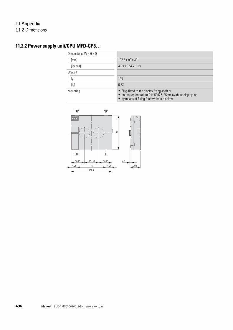
11 Appendix
11.2 Dimensions
496 Manual 11/10 MN05002001Z-EN www.eaton.com
11.2.2 Power supply unit/CPU MFD-CP8…
Dimensions, W x H x D
[mm] 107.5 x 90 x 30
[inches] 4.23 x 3.54 x 1.18
Weight
[g] 145
[lb] 0.32
Mounting • Plug-fitted to the display fixing shaft or• on the top-hat rail to DIN 50022, 35mm (without display) or• by means of fixing feet (without display)
30 g0.2
90
38.75 38.75 4.5
29.57516.25 16.25
107.5

11 Appendix
11.2 Dimensions
Manual 11/10 MN05002001Z-EN www.eaton.com 497
11.2.3 Input/output modules MFD-R.. , MFD-T..
11.2.4 MFD-80-XM protective diaphragm
Dimensions, when installed, W x H x D
[mm] 89 x 90 x 25
[inches] 3.5 x 3.54 x 0.98
Dimensions, when removed, W x H x D
[mm] 89 x 90 x 44
[inches] 3.5 x 3.54 x 1.73
Weight
MFD-R..; MFD-T..[g] 150; 140
MFD-R..; MFD-T..[lb] 0.33; 0.31
Mounting Snap fitted into the power supply module
90 m
m (3
.54”
)
88.1 mm (3.47”) 25 mm
(0.98”)
19 mm
(0.75”)
Dimensions, W x H x D
[mm] 88 x 88 x 22.5
[inches] 3.46 x 3.46 x 0.98
Weight
[g] 25
[lb] 0.055
Mounting Is fitted over the display/function keys (with silver bezel)
88.5 22.5
88.5

11 Appendix
11.2 Dimensions
498 Manual 11/10 MN05002001Z-EN www.eaton.com
11.2.5 MFD-80-XS protective cover
Dimensions, W x H x D
[mm] 86.5 x 94 x 25
[inches] 3.41 x 3.41 x 0.98
Weight
[g] 36
[lb] 0.079
Mounting Is fitted over the display/function keys (without silver bezel)
86.5 25
95

11 Appendix
11.3 Technical data
Manual 11/10 MN05002001Z-EN www.eaton.com 499
11.3 Technical data
11.3.1 Standards
11.3.2 General ambient conditions
MFD
Standards EN 55011, EN 55022, IEC EN 61000-4, IEC60068-2-6, IEC60068-2-27
Climatic conditions (damp heat constant to IEC 60068-2-78; cyclical to IEC 60068-2-30)(cold to IEC 60068-2-1, heat to IEC 60068-2-2)
Operating ambient temperatureInstalled horizontally/vertically
°C, (°F) –25 - 55, (–13 - 131)
Condensation (power supply unit/CPU; inputs/outputs) Prevent condensation by means of suitable measures
Legibility of the display (–10 to 0 °C with back-lighting switched on, continuous duty)
°C, (°F) –5 - 50, (23 - 122)
Storage/transport temperature °C, (°F) –40 - 70, (–40 - 158)
Relative humidity (IEC 60068-2-30), non-condensing % 5 - 95
Air pressure (in operation) hPa 795 - 1080
Ambient mechanical conditions
Pollution degree
Power supply unit/CPU; inputs/outputs 2
Display/operating unit 3
Protection type (EN 50178, IEC 60529, VBG4)
Power supply unit/CPU; inputs/outputs IP20
Display/operating unit IP65, Type 3R, Type 12R
Display/operating unit with protective cover IP65, Type 3R, Type 12R
Display/operating unit with protective diaphragm IP65, NEMA Type 4X(Type 3R rain-tight andType 12 dust-tight)
Vibration (IEC 60068-2-6)
Constant amplitude 0.15 mm Hz 10 - 57
Constant acceleration, 2 g Hz 57 - 150
Shocks (IEC 60068-2-27) semi-sinusoidal 15 g/11 ms Shocks 18
Drop (IEC 60068-2-31) Drop height mm 50
Free fall, when packed (IEC 60068-2-32) m 1
Electromagnetic compatibility (EMC)
Electrostatic discharge (ESD), (IEC/EN 61000-4-2, severity level 3)
Air discharge kV 8
Contact discharge kV 6

11 Appendix
11.3 Technical data
500 Manual 11/10 MN05002001Z-EN www.eaton.com
Electromagnetic fields (RFI), (IEC/EN 61000-4-3) V/m 10
Radio interference suppression (EN 55011, EN 55022, IEC 61000-6-1, 2, 3, 4), limit class
B
Fast transient burst (IEC/EN 61000-4-4, severity level 3)
Supply cables kV 2
Signal cables kV 2
High energy pulses (Surge) MFD (IEC/EN 61000-4-5, severity level 2), power cable symmetrical
kV 0.5
Line-conducted interference (IEC/EN 61000-4-6) V 10
Insulation resistance
Clearance in air and creepage distances EN 50178, UL 508, CSA C22.2, No 142
Insulation resistance EN 50178
Overvoltage category/pollution degree II/2
Tools and cable cross-sections
Solid, minimum to maximum mm2 0.2 - 4
AWG 24 - 12
Flexible with ferrule, minimum to maximum mm2 0.2 - 2.5
AWG 24 - 12
Slot-head screwdriver, width mm 3.5 x 0.5
inch 0.14 x 0.02

11 Appendix
11.3 Technical data
Manual 11/10 MN05002001Z-EN www.eaton.com 501
11.3.3 Display/operating unit
MFD-80, MFD80-B
Power supply
Power supply using power supply unit/CPU MFD-CP8..
LCD display
Type Graphic/monochrome
Visible area W x H mm 62 x 33
Size of pixels mm 0.4 x 0.4
Number of pixels (W x H) 132 x 64
Spacing (pixel centre to pixel centre) mm 0.42
LCD backlight Yes
Backlight color Yellow/green
Backlight can be switched on and off in the visualization application via LE1
Yes
LEDs
Number of LEDs, can be used and programmed in visualization applications
2
Operator buttons
Number 9
Can be used and programmed in visualization applications
9
Mechanical lifespan of pushbuttons Operating elements
Normally 1 x 10⁶
Pushbutton illumination (LED)
Number 5
Color green

11 Appendix
11.3 Technical data
502 Manual 11/10 MN05002001Z-EN www.eaton.com
11.3.4 Power supply
11.3.4.1 AC Power supply
11.3.4.2 Voltage supply:DC
MFD-AC-CP8...
Rated operational voltage
Rated value (sinusoidal) Ue V AC, (%)
100/110/115/120/230/240 AC (+10/-15)
permissible range V AC 85 - 264
Frequency, tolerance Hz (%) 50/60 (± 5)
Input current consumption
At 115/120 V AC 60 Hz mA Normally 90
at 230/240 V AC 50 Hz mA part no. 60
Voltage dips, IEC/EN 61131-2 ms 10
Heat dissipation
At 115/120 V AC VA part no. 11
at 230/240 V AC VA part no. 15
MFD-CP8...
Rated operational voltage
Rated value Ue V DC, (%)
24 DC (-15/+20)
permissible range V DC 20.4 - 28.8
Ripple % ≦ 5
Input current
For 24 V DC, MFD-CP8… mA part no. 125
for 24 V DC, MFD-CP8 + MFD80… mA part no. 250
at 24 V DC, MFD-CP8, MFD80… and MFD-R…/MFD-T…
mA part no. 270
Voltage dips (IEC/EN 61131-2)
ms 10
Heat dissipation
For 24 V DC, MFD-CP8… W part no. 3
for 24 V DC, MFD-CP8 + MFD80… W part no. 6
at 24 V DC, MFD-CP8, MFD80… and MFD-R…/MFD-T…
W Normally 6.5
Fuse CSA ≧ 1 - ≦ 4

11 Appendix
11.3 Technical data
Manual 11/10 MN05002001Z-EN www.eaton.com 503
11.3.5 Central processing unit, real-time clock/timing relay/memoryA super capacitor or so-called double layer capacitor is provided to back up the power supply for the real-time clock.
The full charge of the double layer capacitor is achieved if the MFD device has been connected to the power supply for 24 hours.
→ The following charts show the backup time for a fully charged capacitor.
Back-up/accuracy of the MFD-CP8... real-time clock (see figure)
Back-up time
① Backup time (hours) with fully charged capacitor② Service life (years)
Accuracy of the real-time clock s/day Normally ± 2 (± 0.2 h⁄Year) The accuracy of the real-time clock can vary, depending on the average ambient air temperature, up to ± 5 s⁄Day (± 0.5 h⁄Year).
Back-up/accuracy of the MFD-CP10... real-time clock (see figure)
Back-up time
① Backup time (hours) with fully charged capacitor② Service life (years)
Accuracy of the real-time clock s/day Normally ± 0.17 (± 1 min⁄year, in an operating temperature range 0 °C - 40 °C, 32 °F - 104 °F) The accuracy of the real-time clock can vary (2 min⁄year) depending on the operating ambient temperature range -25 °C - 55°C, 23 °F - 122 °F to ± 0.34 s⁄day .
a
b
180200
160140120100806040200
0 2 4 6 8 10 2012 141 3 5 7 9 11 13
55°C
25°C
15 17 1916 18
a
b
120
100
80
60
40
20
00 2 4 6 8 10 2012 141 3 5 7 9 11 13 15 17 1916 18
55°C
25°C

11 Appendix
11.3 Technical data
504 Manual 11/10 MN05002001Z-EN www.eaton.com
Repetition accuracy of timing relays
Accuracy of timing relay (of value) % ± 0.02
Resolution
Range “S” ms 5
Range “M:S” s 1
Range “H:M” min 1
Memory
Possible Current paths 256
Possible contacts in series 4
Coil per circuit connection 1
Program memory MFD-CP8... for program/circuit diagram
KByte 8
Program memory MFD-CP10... for program/circuit diagram
KByte 16
MFD-CP8... screen memory (visualization)
KByte 24
MFD-CP10... screen memory (visualization)
KByte 48
Storage of programs (Zero-voltage safe, I.e. retentive)
FRAM
Retentive memory
Size - MFD-CP8... Byte 200
Size - MFD-CP10... Byte 400
Operating Hours Counter Byte 16
Write cycles of the retentive memory (minimum)
1000000000 (1010) (read/write cycles)

11 Appendix
11.3 Technical data
Manual 11/10 MN05002001Z-EN www.eaton.com 505
11.3.6 Inputs
11.3.6.1 Digital inputs 115/230 V AC
MFD-AC-R16
Digital inputs 115/230 V AC
Number 12
Status Display LCD display (if provided)
Potential isolation
from power supply no
between digital inputs no
from the outputs Yes
to PC interface, memory card, network NET, easyLink
Yes
Rated voltage L (sinusoidal)
at signal ”0” V AC 0 – 40
at signal ”1” V AC 79 – 264
Rated frequency Hz 50 – 60
Input current at signal "1"
I1 – I12 mA 12 x 0.2 (at 115 V AC, 60 Hz)12 x 0.5 (at 230 V AC, 50 Hz)
Deceleration time
Delay time (0–>1⁄1–>0) I1 – I12, 50⁄60 Hz 10 / 100
Max. admissible cable length (per input)
I1 – I12 m part no. 60

11 Appendix
11.3 Technical data
506 Manual 11/10 MN05002001Z-EN www.eaton.com
11.3.6.2 Digital inputs 24 V DC
MFD-R(A)1..., MFD-T(A)1... MFD-T(A)P...
Number 6
Inputs can be used as analog inputs
2 (I11, I12)
Status Display via MFD80 via MFD80
Potential isolation
from power supply no no
between digital inputs no no
from the outputs Yes Yes
to PC interface, memory card, easyLink Yes Yes
to network easyNet Yes Yes
Rated operational voltage Ue V DC 24 24
at signal ”0” Ue V DC < 5 (I1 – I6, I9, I10)< 8 (I7, I8, I11, I12)
< 5 (I1 – I4) < 8 (I11, I12)
at signal ”1” Ue V DC > 15.0 (I1 – I6, I9, I10), > 8.0 (I7, I8, I11, I12)
> 15.0 (I1 – I4), > 8.0 (I11, I12)
Input current at signal "1"
I1 to I4 mA – 3.3 (at 24 V DC)
mA 3.3 (at 24 V DC) –
I11, I12 mA 2.2 (at 24 V DC) 2.2 (at 24 V DC)
Hardware delay time „0“ -> „1“
Debounce ON ms 20 20
Debounce OFF ms Normally 0.025 (I1 – I4)normally 0.25 (I5, I6, I9, I10)normally 0.15 (I7, I8, I11, I12)
Normally 0.1 (I1 – I4)Normally 0.25 (I11 – I12)
Hardware delay time„1“ -> „0“
Debounce ON ms 20 20
Debounce OFF ms Normally 0.025 (I1 - I4)normally 0.25 (I5, I6, I9, I10), normally 0.15 (I7, I8, I11, I12)
normally 0.1 (I1 – I4),normally 0.2 (I11, I12)
Cable length (unscreened) m 100 100
Rapid counter inputs
Number 4 (I1, I2, I3, I4) 4 (I1, I2, I3, I4)
Cable length, shielded m 20 20
High-speed up and down counter
Counter frequency kHz ≦ 3 ≦ 3
Pulse shape Square Square
Pulse Pause Ratio 1:1 1:1

11 Appendix
11.3 Technical data
Manual 11/10 MN05002001Z-EN www.eaton.com 507
11.3.6.3 Analog inputs
Frequency Counter
Quantity 4 (I1, I2, I3, I4) 4 (I1, I2, I3, I4)
Counter frequency kHz ≦ 3 ≦ 3
Pulse shape Square Square
Pulse Pause Ratio 1:1 1:1
Incremental Encoder
Number 2 (I1 + I2, I3 + I4) 2 (I1 + I2, I3 + I4)
Counter frequency kHz ≦ 3 ≦ 3
Pulse shape Square Square
Signal offset 90° 90°
Pulse Pause Ratio 1:1 1:1
MFD-R(A)1..., MFD-T(A)1... MFD-T(A)P...
MFD-R..., MFD-T...
Number 4 (I7, I8, I11, I12), for MFD-T(A)P: 2 (I11, I12)
Potential isolation
from power supply no
To the digital inputs no
from the outputs Yes
to PC interface, memory card, network NET, easyLink
Yes
Input type DC voltage
Signal range V DC 0 – 10
Resolution, analog V 0.01
Resolution, digital V 0.01
Resolution, digital Bit 10 (value 0 – 1023)
Input impedance kΩ 11.2
Accuracy of actual value
two MFD devices % ± 3
Within a single device % ± 2
Conversion time, analog/digital
Debounce ON: ms 20
Debounce OFF ms each CPU cycle
Input current mA < 1
Cable length screened m < 30

11 Appendix
11.3 Technical data
508 Manual 11/10 MN05002001Z-EN www.eaton.com
11.3.6.4 Analog inputs temperature monitoring and 0 - 10 V
MFD-TP, MFD-TAP
Analog inputs temperature resistance Pt100 or Ni1000 sensors
Number 2 x Pt100 or 2 x Nt1000 (according to type)
Input type resistance sensor
Platinum sensor Pt100 according to DIN EN 60751, IEC 751
Nickel sensor Ni1000 according to DIN 43760
Temperature range
Pt100, Range A, selectable °C , (°F) –40 to +90, (-40 to 194); 0 to 250, (32 to 482); 0 to 400, (32 to 752)
Ni1000, Range A, selectable °C , (°F) –40 to +90, (-40 to 194); 0 to 250, (32 to 482)
Pt100, Range B °C , (°F) 0 to +850, (+32 to +1562); - 200 to +200, (–328 to +392)
Potential isolation
from power supply no
To the digital inputs no
from the outputs Yes
to PC interface, memory card, network NET, easyLink
Yes
Resolution digital, scaling per sensor
With operands "IA" and "MD", selectable under scaling
Bit 12 (0 to 4095)
With operand "MD", selectable under scaling °C, (°F) 1, 0.1; (1, 0.1)
Measurement value resolution analog/digital Bit Depending upon the scaling
Measuring current mA < 1.6
Damage limit (in the case of a wiring error) Apply external voltage
Measurement method Two or three wire per sensor, selectable by connection of sensor
Accuracy (without electromagnetic compatibility interference)
Two MFD devices one above the other % Typically 1; maximal 1.6 (Pt); 1.2 (Ni)
Pt100-sensor (Offset error, linearity error, repetition accuracy, temperature dependency of the device included)
% ±0.8 of measurement range
Ni1000-sensor (Offset error, linearity error, repetition accuracy, temperature dependency of the device include)
% ±0.6 of measurement range
Conversion time, analog/digital
Without sampling time setting, selectable per sensor
ms 200
With sampling time (adjustable), selectable per sensor
ms 200 to 65535

11 Appendix
11.3 Technical data
Manual 11/10 MN05002001Z-EN www.eaton.com 509
Additional measurement aids
Filtering (Software), smoothing of analog input signals (PT1 behavior), only with set sampling time, selectable per sensor
Yes
Filter for the suppression of certain frequencies and their multiples
Hz 50, 60, 250, 500
Diagnostics
Card diagnostic Yes
Conductor or Wire break diagnostic per sensor Yes
lower measurement range sensor undershot Yes
Above upper measurement range Yes
Cable length screened m < 10
Analog inputs 0 - 10 V of MFD-T(A)P (see above)
MFD-TP, MFD-TAP

11 Appendix
11.3 Technical data
510 Manual 11/10 MN05002001Z-EN www.eaton.com
11.3.6.5 Relay outputs
MFD-R16, MFD-AC-R16
Number 4
Outputs in groups of –
Parallel switching of outputs to increase performance
Not permissible
Protection of an output relay Miniature circuit-breaker B16 or fuse 8 A (slow).
Potential isolation
from power supply Yes
from the inputs Yes
to PC interface, memory card, network NET, easyLink
Yes
Safe isolation V AC 300
Basic insulation V AC 600
Lifespan, mechanical Switch operations
10x 106
Contacts
conventional thermal current (UL/CSA) CSA 8 (10)
Recommended for load: 12 V AC/DC mA > 500
short-circuit proof cos ϕ = 1, characteristic B16 at 600 A
CSA 16
Short-circuit proof cos ϕ = 0.5 - 0.7; characteristic B16 at 900 A
CSA 16
Rated impulse withstand voltage Uimp contact coil
kV 6
Rated operating voltage Ue V AC 250
Rated insulation voltage Ui V AC 250
Safe isolation to EN 50178 between coil and contact
V AC 300
Safe isolation to EN 50178 between two contacts
V AC 300
Making capacity, IEC 60947
AC–-15, 250 V AC, 3 A (600 ops./h) Switch operations
300000
DC-13, L/R ≦ 150 ms, 24 V DC, 1 A (500 S/h) Switch operations
200000
Breaking capacity, IEC 60947
AC–-15, 250 V AC, 3 A (600 ops./h) Switch operations
300000
DC-13, L/R ≦ 150 ms, 24 V DC, 1 A (500 S/h) Switch operations
200000

11 Appendix
11.3 Technical data
Manual 11/10 MN05002001Z-EN www.eaton.com 511
Filament bulb load
1000 W at 230/240 V AC Switch operations
25000
500 W at 115/120 V AC Switch operations
25000
Fluorescent lamp load
Fluorescent lamp load 10 x 58 W at 230/240 V AC
With series-connected electrical device Switch operations
25000
Uncompensated Switch operations
25000
Fluorescent lamp load 1 x 58 W at 230/240 V AC, conventionally compensated
Switch operations
25000
Switching Frequency
mechanical operations Switch operations
10x 106
Switching Frequency Hz 10
Resistive load/lamp load Hz 2
Inductive load Hz 0.5
UL/CSA
Continuous current at 240 V AC CSA 10
AC
Control circuit rating codes (utilization category)
B 300 Light Pilot Duty
Max. rated operational voltage V AC 300
max. thermal continuous current cos ϕ = 1 at B 300
CSA 5
max. make/break cos ϕ ≠ capacity 1 at B 300
VA 3600/360
DC
Control circuit rating codes (utilization category)
R 300 Light Pilot Duty
Max. rated operational voltage V DC 300
Max. thermal continuous current at R 300 CSA 1
Max. make/break capacity at R 300 VA 28/28
MFD-R16, MFD-AC-R16

11 Appendix
11.3 Technical data
512 Manual 11/10 MN05002001Z-EN www.eaton.com
11.3.6.6 Transistor outputs
MFD-T...
Number 4
Rated operational voltage Ue V DC 24
permissible range Ue V DC 20.4 – 28.8
Ripple % ≦ 5
Supply current
at signal ”0” typ.⁄max. mA 18/32
at signal ”1” typ.⁄max. mA 24/44
Protection against polarity reversalCaution! If voltage is applied to the outputs when the polarity of the supply voltage is reversed, this will result in a short-circuit.
yes
Potential isolation
from power supply Yes
from the inputs Yes
to PC interface, memory card, network NET, easyLink
Yes
Rated operational current at signal "1", maximum
Ie CSA 0.5
Lamp load without Rv W 5 (Q1 – Q4)
Residual current at signal "0" per channel mA < 0.1
Max. output voltage
With condition "0" at external load < 10 MΩ
V 2.5
with condition “1” at Ie = 0.5 A V U = Ue -1 V
Short-circuit protectionthermal (Q1 to Q4), (carry out evaluation via diagnostics input I16).
Yes
Short-circuit tripping current for Ra ≦ 10 mΩ(depending on number of active channels and their load)
CSA 0.7 ≦ Ie ≦ 2 per output
Maximum, total short-circuit current CSA 8
Peak short-circuit current CSA 16
Thermal cutout Yes
max. operating frequency at constant resistive load RL < 100 kΩ (dependant on program and load)
Operations/h
40000
Parallel connection of outputs Yes
with resistive load, with inductive load with external suppressor circuit (see section Connecting transistor outputs), with combination within a group
Group 1: Q1 to Q4

11 Appendix
11.3 Technical data
Manual 11/10 MN05002001Z-EN www.eaton.com 513
Inductive load without external suppressor circuit
General explanations: T0.95 = time in milliseconds until 95 % of the stationary current is reached
Utilization category in groups for
• Q1 to Q4, Q5 to Q8
Other inductive loads:
Number of outputs (max.) 4
Max. total currentCaution! Outputs must be actuated simultaneously and for the same time duration.
CSA 2
Status indication of the outputs LCD display (if provided)
T0.95 ≈ 3 x T0.65 = 3 xL
R
T0.95 = 1 msR = 48 ΩL = 16 mH
Utilization factor per group g = 0.25
Relative duty factor % 100
Max. switching frequencyf = 0.5 HzMax. duty factorDF = 50 %
Switching operations/h
1 500
DC13
T0.95 = 72 msR = 48 ΩL = 1.15 H
Simultaneity factor g = 0.25
Relative duty factor % 100
Max. switching frequencyf = 0.5 HzMax. duty factorDF = 50 %
Switching operations/h
1 500
T0.95 = 15 msR = 48 ΩL = 0.24 H
Simultaneity factor g = 0.25
Relative duty factor % 100
Max. switching frequencyf = 0.5 HzMax. duty factorDF = 50 %
Switch operations/h
1 500
Inductive loading with external suppressor circuit for each load (→ Section "2.6.2 Connecting digital transistor outputs“, page 78)
Simultaneity factor g = 1
Relative duty factor % 100
Max. switching frequencyMax. duty factor
Switch operations/h
Depending on the suppressor circuit
MFD-T...

11 Appendix
11.3 Technical data
514 Manual 11/10 MN05002001Z-EN www.eaton.com
11.3.7 Analog output
MFD-RA17, MFD-TA...
Quantity 1
Potential isolation
from power supply no
To the digital inputs no
From the digital outputs Yes
to PC interface, memory card, network NET, easyLink
Yes
Output type DC voltage
Signal range V DC 0 – 10
Max. output current CSA 0.01
Load resistance 1 kΩ
Overload and short-circuit protection Yes
Resolution, analog V DC 0.01
Resolution, digital Bit MFD-TAP: 12 (0 - 4095) at QA01, MD
Recovery time μs 100
Accuracy
-25 °C – 55 °C % 2
25C % 1
Conversion time, analog/digital ms each CPU cycle

11 Appendix
11.3 Technical data
Manual 11/10 MN05002001Z-EN www.eaton.com 515
11.3.8 NET network
1) Bus lengths above 40 m can only be achieved with cables with reinforced cross-section and connection adapter.
MFD-...-NT
Number of stations 8
Bus length/transmission speed1) m/Kbaud 6/1 00025/50040/250125/125300/50700/201 000/10
Potential isolation
To power supply, inputs, outputs, easyLink, PC interface, memory module Yes
Bus termination (→ accessories)
First and last station Yes
Plug connector (→ accessories) poles 8
Type RJ45
Cable cross-sections, with cable lengths and cable resistance/m
Cross-section up to 1 000, < 16 mΩ/m mm2 (AWG) 1.5 (16)
Cross-section up to 600, < 26 mΩ/m mm2 (AWG) 0.75 to 0.8 (18)
Cross-section up to 600, < 26 mΩ/m mm2 (AWG) 0.5 to 0.6 (20, 19)
Cross-section up to 400 m, < 40 mΩ/m mm2 (AWG) 0.34 to 0.5 (22, 21, 20)
Cross-section up to 250 m, < 60 mΩ/m mm2 (AWG) 0.25 to 0.34 (23, 22)
Cross-section up to 175 m, < 70 mΩ/m mm2 (AWG) 0.13 (26)
Cross-section up to 40 m, < 140 mΩ/m mm2 (AWG) 1.5 (16)

11 Appendix
11.4 List of function blocks
516 Manual 11/10 MN05002001Z-EN www.eaton.com
11.4 List of function blocks
Function block
Meaning of abbreviation
Function block designation Page From dev. vers. no.
CSA Analog value comparator Analog value comparator 199 01
AR Arithmetic Arithmetic 204 01
BC Block Compare Data block comparator 208 01
BT Block Transfer Data block transfer 216 01
BV Boolean operation Boolean operation 228 01
C Counter Counter 232 01
CF Counter Frequency Frequency Counter 238 01
CH Counter High Speed High-speed counters 243 01
CI Counter fast Incremental Value Encoder
High-speed incremental value counter
249 01
CP Comparators Comparator 255 01
DB Data Block Data Function Block 258 01
DC DDC controller (direct Digital Control)
PID Controller 261 01
FT Filter PT1 Signal Smoothing Filter 268 01
GT GET GET (Value from NET) 273 01
HW Hora(lat) Week Weekly timer 276 01
HY Hora(lat) Year Year time switch 282 01
JC Jump Conditional Conditional Jump 291 05
LB Label Jump label 294 05
LS Linear Scaling Value Scaling 295 01
MR Master Reset Master Reset 300 01
MX Multiplexer Data multiplexer 303 MFD-CP10..
NC Numeric Coding Numerical Converter 307 01
OT Operating Time Operating Hours Counter 312 01
PT PUT PUT (Value on NET) 315 01
PW Pulse Width Modulation Pulse Width Modulation 319 01
SC Synchronize Clocks Synchronize clock via NET 323 01
SR Shift Register Shift Register 325 05
ST Set Time Set cycle time 337 01
T Timing relays Timing Relay 340 01
TB Table function Table Function 350 05
VC Value Capsuling Value Limit 355 01

11 Appendix
11.4 List of function blocks
Manual 11/10 MN05002001Z-EN www.eaton.com 517
11.4.1 Function block coilsThe following table is a general overview of the function block contacts. A detailed overview of all contacts used in the circuit diagram is provided in → Section "11.5 Memory requirement“ on page 520.
Table 47: General overview of the function block coils
Coil Meaning of abbreviation
Description
BD Backward Direction Bit data input, backwards shift direction
BP Backward Pulse Trigger coilClock input, backward shift direction
C_ Count input Counter input
D_ Direction input Count Direction
ED Enable Differential Ratio Activate differential component
EI Enable Integral Ratio Activate integral component
EN Enable Enable function block
EP Enable Proportional component
Activate proportional component
FD Forward Direction Bit data input, forwards shift direction
FP Forward Pulse Trigger coilClock input, forward shift direction
RE Reset Reset actual value to zero
RF Read First Trigger coilOn detecting a rising edge (trigger) and EN = 1 the oldest value entered in the table is read out and supplied at output QV (FIFO function)
RL Read Last Trigger coilOn detecting a rising edge (trigger) and EN = 1 the newest value entered in the table is read out and output at output QV (LIFO function)
SE Set Enable Set to a predefined value
ST Stop Stop block processing
T_ Trigger Trigger coil for starting the timing relay
WP Word Pulse Trigger coilOn detecting a rising edge (trigger) and EN = 1 the value is entered in the table

11 Appendix
11.4 List of function blocks
518 Manual 11/10 MN05002001Z-EN www.eaton.com
11.4.2 Function block contactsThe following table is a general overview of the function block contacts. A detailed overview of all contacts used in the circuit diagram is provided in → Section "11.5 Memory requirement“ on page 520.
Table 48: General overview of the function block contacts
Contact Meaning of abbreviation
Description
AC Active Status 1, as long as the input value has been buffered but not yet transferred to the easyNet with the PUT function block.
CY Carry Status 1, if the value range is exceeded
E1 Error 1 Error 1, dependent on function block
E2 Error 2 Error 2, dependent on function block
E3 Error 3 Error 3, dependent on function block
EQ Equal Comparison result, status 1 if values equal.
FB Fall Below Status 1, if the actual value is less than or equal to the lower setpoint value
GT Greater Than Status 1 if the value at I1 > I2
LI Limit Indicator Value range manipulated variable exceeded
LT Less Than Status 1 if the value at I1 < I2;
OF Overflow Status 1, if the actual value is greater than or equal to the upper setpoint value;
q Output (Q...) Switch output
QV Output Value Current actual value of the function block (e.g. counter value);
Space units
Table Empty Status 1 if the table is empty
TF Table Full Status 1 if the table is full
ZE Zero Status 1, if the value of the element input QV is equal to zero;

11 Appendix
11.4 List of function blocks
Manual 11/10 MN05002001Z-EN www.eaton.com 519
11.4.3 Function block inputs (constants, operands)
Input Meaning of abbreviation
Description
BF Standard Frequency change in braking phase
F1 Factor 1 Gain factor for I1 (I1 = F1 x Value)
F2 Factor 2 Gain factor for I2 (I2 = F2 x Value)
FO Frequency Operation Operating Frequency
FS Frequency Start Start Frequency
HY HYsteresis Switching hysteresis for value I2 (Value HY applies to positive and negative hysteresis.)
I1…I8 Input 1 to Input 8 1. to 8. input word
KP Channel Channel number Value range: 0...7
KP Standard Proportional Gain
ME Minimum make time Minimum make time
MV Manual Value Manual manipulated variable
NO Numbers Of elements Number of elements
OS OffSet Offset for the value I1
PI Standard Number of steps in Jog mode
PF Standard Frequency in jog mode
PD Period of Duration Period Duration
RF Standard Frequency change in acceleration phase
SH Setpoint High Upper Limit Value
SL Setpoint Low Lower Limit Value
SV Set Value Defined actual value (Preset)
TC Standard Scan Time
TG Standard Recovery time
TN Standard Derivate time
TV Standard Reset time
X1 X1, interpolation point 1 abscissa
Lower value of source range
X2 Interpolation point 2 abscissa
Upper value of source range
Y1 Interpolation point 1 ordinate
Lower value of target range
Y2 Interpolation point 2 ordinate
Upper value of target range

11 Appendix
11.5 Memory requirement
520 Manual 11/10 MN05002001Z-EN www.eaton.com
11.4.4 Function block output (operands)
11.4.5 Other operands
11.5 Memory requirementThe following table serves as an overview of the memory requirement of the for rungs, function blocks and their associated constants.
Output Meaning of abbreviation
Description
D1…D8 Data 1…8 Output values
QN Output Number Number of table entries present, 0…16
QV Output Value Output value
Other operands
Meaning of abbreviation
Description
MB Marker byte 8-Bit value
IA Input Analog Analog input (if available on device!)
MW Marker Word 16-Bit value
QA Output Analog Analog output (if present on the device!)
MD Marker Double Word 32-Bit value
NU NUmber Constant, value range from –2 147 483 648 to +2 147 483 647
→ Avoid empty rungs dispersed between written rungs after operands have been deleted. These kinds of empty rungs take up just as much space as a written rung.
Space requirement per rung/function block
Space requirement per constant at function block input
Byte Byte
Rung 20 –
Function Blocks
CSA 68 4
AR 40 4
BC 48 4
BT 48 4
BV 40 4
C 52 4
CF 40 4
CH 52 4
CI 52 4
CP 32 4

11 Appendix
11.5 Memory requirement
Manual 11/10 MN05002001Z-EN www.eaton.com 521
DB 36 4
DC 96 4
FT 56 4
GT 28 -
HW 68 4 (per channel)
HY 68 4 (per channel)
JC 20 -
LB - -
LS 64 4
MR 20 -
MX MFD-CP10... 96 4
NC 32 4
OT 36 4
PT 36 4
PW 48 4
SC 20 -
SR 96 4
ST 24 4
T 48 4
TB 112 4
VC 40 4
: - -
Space requirement per rung/function block
Space requirement per constant at function block input
Byte Byte

11 Appendix
11.6 Basic and extended Western European character set
522 Manual 11/10 MN05002001Z-EN www.eaton.com
11.6 Basic and extended Western European character set
Table 49: Western European basic character set
Unicode (hex)
Character Unicode (hex)
Character Unicode (hex)
Character Unicode (hex)
Character
U+0020 U+0040 @ U+0060 `
U+0021 ! U+0041 CSA U+0061 a U+00A1 ¡
U+0022 " U+0042 B U+0062 b U+00A2 ¢
U+0023 # U+0043 C U+0063 c U+00A3 £
U+0024 $ U+0044 D U+0064 d
U+0025 % U+0045 E U+0065 e U+00A6 ¦
U+0026 & U+0046 F U+0066 f U+00A9 ©
U+0027 ' U+0047 G U+0067 g
U+0028 ( U+0048 H U+0068 h U+00B0 °
U+0029 ) U+0049 I U+0069 I U+00B1 ±
U+002A * U+004A J U+006A j U+00B2 ²
U+002B + U+004B KP U+006B k U+00B3 ³
U+002C , U+004C L U+006C l U+00B4 ´
U+002D - U+004D M U+006D m U+00B5 μ
U+002E . U+004E N U+006E n
U+002F / U+004F O U+006F o U+00BF ¿
U+0030 0 U+0050 KP U+0070 p
U+0031 1 U+0051 q U+0071 q U+201E „
U+0032 2 U+0052 R U+0072 r U+2030 ‰
U+0033 3 U+0053 S U+0073 s U+20AC €
U+0034 4 U+0054 T U+0074 t U+2190 ←
U+0035 5 U+0055 U U+0075 u U+2191 ↑
U+0036 6 U+0056 V U+0076 v U+2192 →
U+0037 7 U+0057 W U+0077 w U+2193 ↓
U+0038 8 U+0058 X U+0078 x U+2194 ↔
U+0039 9 U+0059 Y U+0079 y U+2195 ↔
U+003A : U+005A Z U+007A z U+2264 ≤
U+003B ; U+005B [ U+007B U+2265 ≥
U+003C < U+005C \ U+007C | U+2588
U+003D = U+005D ] U+007D ] U+25A0
U+003E > U+005E ^ U+007E ~ U+25A1
U+003F ? U+005F _ U+007F U+25AA

11 Appendix
11.6 Basic and extended Western European character set
Manual 11/10 MN05002001Z-EN www.eaton.com 523
Table 50: Extension of the Western European basic character set
The Western European basic and expansion character set shown above can be shown on the MFD.
As well as the Western European basic character set, you can also display characters (code page) of the Central European and Cyrillic code page (see online help for programming software).
Unicode (hex)
Character Unicode (hex)
Character Unicode (hex)
Character Unicode (hex)
Character
U+00C0 À U+00E0 à
U+00C1 Á U+00E1 á
U+00C2  U+00E2 â U+0152 Œ
U+00C3 à U+00E3 ã U+0153 œ
U+00C4 Ä U+00E4 ä
U+00C5 Å U+00E5 å U+0160 Š
U+00C6 Æ U+00E6 æ U+0161 š
U+00C7 Ç U+00E7 ç
U+00C8 È U+00E8 è U+0178 Ÿ
U+00C9 É U+00E9 é U+017D Ž
U+00CA Ê U+00EA ê U+017E ž
U+00CB Ë U+00EB ë
U+00CC Ì U+00EC ì
U+00CD Í U+00ED í
U+00CE Î U+00EE î
U+00CF Ï U+00EF ï
U+00D0 Ð U+00F0 ð
U+00D1 Ñ U+00F1 ñ
U+00D2 Ò U+00F2 ò
U+00D3 Ó U+00F3 ó
U+00D4 Ô U+00F4 ô
U+00D5 Õ U+00F5 õ
U+00D6 Ö U+00F6 ö
U+00D7 U+00F7
U+00D8 Ø U+00F8 ø
U+00D9 Ù U+00F9 ù
U+00DA Ú U+00FA ú
U+00DB Û U+00FB û
U+00DC Ü U+00FC ü
U+00DD Ý U+00FD ý
U+00DE U+00FE þ
U+00DF ß U+00FF ÿ

11 Appendix
11.7 Central European expansion character set
524 Manual 11/10 MN05002001Z-EN www.eaton.com
You can use the Windows character table to enter characters that cannot be entered directly via the keyboard. Open the Windows XP character map via Start -> Programs -> Accessories -> System Tools -> Character Map or alternatively with Start -> Run -> Charmap.
11.7 Central European expansion character set
Unicode (hex)
Character Unicode (hex)
Character Unicode (hex)
Character Unicode (hex)
Character
U+00C0 - U+00E0 - U+0100 - U+0150 Ő
U+00C1 Á U+00E1 á U+0101 - U+0151 ő
U+00C2 Â U+00E2 â U+0102 Ă U+0154 Ŕ
U+00C3 - U+00E3 - U+0103 ă U+0155 ŕ
U+00C4 Ä U+00E4 ä U+0104 Ą U+0158 Ř
U+00C5 - U+00E5 - U+0105 ą U+0159 ř
U+00C6 - U+00E6 - U+0106 Ć U+015A Ś
U+00C7 Ç U+00E7 ç U+0107 ć U+015B ś
U+00C8 - U+00E8 - U+015E Ş
U+00C9 É U+00E9 é U+010C Č U+015F ş
U+00CA - U+00EA - U+010D č
U+00CB Ë U+00EB ë U+010E Ď
U+00CC - U+00EC - U+010F ď U+0160 Š
U+00CD Í U+00ED í U+0110 Đ U+0161 š
U+00CE Î U+00EE î U+0111 đ U+0162 Ţ
U+00CF - U+00EF - U+0163 ţ
U+00D0 - U+00F0 - U+0118 Ę U+0164 Ť
U+00D1 - U+00F1 - U+0119 ę U+0165 ť
U+00D2 - U+00F2 - U+011A Ě U+016E Ů
U+00D3 Ó U+00F3 ó U+011B ě U+016F ů
U+00D4 Ô U+00F4 ô
U+00D5 - U+00F5 - U+0139 Ĺ U+0170 Ű
U+00D6 Ö U+00F6 ö U+013A ĺ U+0171 ű
U+00D7 - U+00F7 - U+013D Ľ U+0179 Ź
U+00D8 - U+00F8 - U+013E ľ U+017A ź
U+00D9 - U+00F9 - U+017B Ż
U+00DA Ú U+00FA ú U+0141 Ł U+017C ż
U+00DB - U+00FB - U+0142 ł U+017D Ž
U+00DC Ü U+00FC ü U+0143 Ń U+017E ž
U+00DD Ý U+00FD ý U+0144 ń
U+00DE - U+00FE - U+0147 Ň U+2013 –
U+00DF ß U+00FF - U+0148 ň

11 Appendix
11.8 Cyrillic expansion character set
Manual 11/10 MN05002001Z-EN www.eaton.com 525
11.8 Cyrillic expansion character set
Unicode (hex)
Character Unicode (hex)
Character Unicode (hex)
Character Unicode (hex)
Character
U+00400 U+0420 Р U+0440 р U+0490 Ґ
U+0401 Ё U+0421 С U+0441 с U+0491 ґ
U+0402 Ђ U+0422 Т U+0442 т
U+0403 Ѓ U+0423 У U+0443 у U+04BA h
U+0404 Є U+0424 Ф U+0444 ф U+04BB h
U+0405 Ѕ U+0425 Х U+0445 х
U+0406 І U+0426 Ц U+0446 ц
U+0407 Ї U+0427 Ч U+0447 ч
U+0408 J U+0428 Ш U+0448 ш
U+0409 Љ U+0429 Щ U+0449 щ
U+040A Њ U+042A Ъ U+044A ъ
U+040B Ћ U+042B Ы U+044B ы
U+040C Ќ U+042C Ь U+044C ь
U+042D Э U+044D э
U+040E Ў U+042E Ю U+044E ю
U+040F Џ U+042F Я U+044F я
U+0410 CSA U+0430 а
U+0411 Б U+0431 б U+0451 ё
U+0412 B U+0432 в U+0452 ђ
U+0413 Г U+0433 г U+0453 ѓ
U+0414 Д U+0434 д U+0454 є
U+0415 E U+0435 е U+0455 ѕ
U+0416 Ж U+0436 ж U+0456 і
U+0417 Э U+0437 э U+0457 ї
U+0418 И U+0438 и U+0458 ј
U+0419 Й U+0439 й U+0459 љ
U+041A К U+043A к U+045A њ
U+041B Л U+043B л U+045B ћ
U+041C М U+043C м U+045C ќ
U+041D Н U+043D н
U+041E О U+043E о U+045E ў
U+041F П U+043F п U+045F џ

11 Appendix
11.8 Cyrillic expansion character set
526 Manual 11/10 MN05002001Z-EN www.eaton.com

Handbuch 11/10 MN05002001Z-DE www.eaton.com 527
Index
AA, analog value comparator/threshold value switch (standard FB) . . . . . . . . . . . . . . . . . . . . . . . . . . . . 199
AddingRung . . . . . . . . . . . . . . . . . . . . . . . . . . . . 102, 170
Switch contact . . . . . . . . . . . . . . . . . . . . . . . 102
Addressing examples . . . . . . . . . . . . . . . . . . . . . . 86
After abort PW entry . . . . . . . . . . . . . . . . . . . . . . 365
ALT pushbutton . . . . . . . . . . . . . . . . . . . . . . . . . . 146
AnalogOperands . . . . . . . . . . . . . . . . . . . . . . . . . . . . 152
Output QA1 . . . . . . . . . . . . . . . . . . . . . . . . . . 114
Output, Technical data . . . . . . . . . . . . . . . . 514
Value output . . . . . . . . . . . . . . . . . . . . . . . . . 403
Analog Input . . . . . . . . . . . . . . . . . . . . . . . . . . . . . 507
AnalogueAnalog value comparator (standard FB) . . 199
Approval, Certification . . . . . . . . . . . . . . . . . . . . 493
AR, Arithmetic . . . . . . . . . . . . . . . . . . . . . . . . . . . 204
Area of application . . . . . . . . . . . . . . . . . . . . . . . . . 19
Arithmetic (standard FB) . . . . . . . . . . . . . . . . . . . 204
Associated variable . . . . . . . . . . . . . . . . . . . . . . . 377
Auxiliary relays -> Markers
BBacklight, LCD display . . . . . . . . . . . . . . . . . . . . 456
Bargraph . . . . . . . . . . . . . . . . . . . . . . . . . . . . . . . . 396
Baud rateCOM-LINK . . . . . . . . . . . . . . . . . . . . . . . . . . . 134
NET Station . . . . . . . . . . . . . . . . . . . . . . . . . . 440
BC, data block comparator (standard FB) . . . . 208
Bit display . . . . . . . . . . . . . . . . . . . . . . . . . . . . . . . 388
Bitmap . . . . . . . . . . . . . . . . . . . . . . . . . . . . . . . . . . 391
Boolean operation (standard FB) . . . . . . . . . . . . 228
Break contactInverting . . . . . . . . . . . . . . . . . . . . . . . . . . . . . 168
BT, Data block Transformer (standard FB) . . . . 216
Bus connection plug . . . . . . . . . . . . . . . . . . . . . . . 84
BUS DELAY . . . . . . . . . . . . . . . . . . . . . . . . . . . . . 441
Bus termination resistor . . . . . . . . . . . . . . . . . . . . 83
BUSY . . . . . . . . . . . . . . . . . . . . . . . . . . . . . . . . . . . . 96
Button editor . . . . . . . . . . . . . . . . . . . . . . . . . . . . 417
Button elements . . . . . . . . . . . . . . . . . . . . . 361, 417
Button field . . . . . . . . . . . . . . . . . . . . . . . . . . . . . . 386
BV, Boolean operation (standard FB) . . . . . . . . 228
CC . . . . . . . . . . . . . . . . . . . . . . . . . . . . . . . . . . . . . . 232
CableCross-section . . . . . . . . . . . . . . . . . . . . . . . . . 87
Length . . . . . . . . . . . . . . . . . . . . . . . . . . . . . . . 87
Protection . . . . . . . . . . . . . . . . . . . . . . . . . . . . 57
Resistance . . . . . . . . . . . . . . . . . . . . . . . . . . . . 87
Cable layout easyNet, network cable . . . . . . . . . 83
Cancel, circuit diagram entry . . . . . . . . . . . . . . . 170
Card -> Memory cardCentral processing unit, Technical data, Real-time clock, Technical data . . . . . . . . . . . . . . . . . . . . . . 503
CF, Frequency counter (standard FB) . . . . . . . . 238
CH, High-speed counter (standard FB) . . . . . . . 243
ChangePassword . . . . . . . . . . . . . . . . . . . . . . . . . . . . 448
ChangingCoils and contacts . . . . . . . . . . . . . . . . . . . . 166
Connections . . . . . . . . . . . . . . . . . . . . . . . . . 169
Contact, Switch duration and time . . . . . . 340
Function block parameters . . . . . . . . . . . . . 194
NET configuration . . . . . . . . . . . . . . . . . . . . . 129
Value (operating method) . . . . . . . . . . . . . . . 28
Changing input values, on function blocks . . . 195
Changing NET ID and position . . . . . . . . . . . . . . 129
Character Set . . . . . . . . . . . . . . . . . . . . . . . . . . . . 373
Character setCentral Europe . . . . . . . . . . . . . . . . . . . . . . . 524
Central European . . . . . . . . . . . . . . . . . . . . . 523
Cyrillic . . . . . . . . . . . . . . . . . . . . . . . . . . . 523, 525
CI, High-speed incremental value counter (standard FB) . . . . . . . . . . . . . . . . . . . . . . . . . . . . 249
Circuit diagramCheck . . . . . . . . . . . . . . . . . . . . . . . . . . . . . . . 173
Creating, example . . . . . . . . . . . . . . . . . . . . . 98
Creation, troubleshooting . . . . . . . . . . . . . . 488
Delete . . . . . . . . . . . . . . . . . . . . . . . . . . 106, 107
Display . . . . . . . . . . . . . . . . . . . . . . . . . . . . . . . 99
Elements . . . . . . . . . . . . . . . . . . . . . . . . . . . . 146
Internal evaluation . . . . . . . . . . . . . . . . . . . . 469
Saving . . . . . . . . . . . . . . . . . . . . . . . . . . . . . . 170
Testing . . . . . . . . . . . . . . . . . . . . . . . . . . . . . . 104
Code page . . . . . . . . . . . . . . . . . . . . . . . . . . . . . . 523

528 Handbuch 11/10 MN05002001Z-DE www.eaton.com
CoilConnecting . . . . . . . . . . . . . . . . . . . . . . . . . . 169
Definition . . . . . . . . . . . . . . . . . . . . . . . . . . . . 147
Deleting . . . . . . . . . . . . . . . . . . . . . . . . . . . . . 168
Entry, changing . . . . . . . . . . . . . . . . . . . . . . . 167
Field . . . . . . . . . . . . . . . . . . . . . . . . . . . . . . . . 157
Function, overview . . . . . . . . . . . . . . . . . . . . 174
Negation . . . . . . . . . . . . . . . . . . . . . . . . . . . . 176
Searching . . . . . . . . . . . . . . . . . . . . . . . . . . . . 171
COM LINKConfigure . . . . . . . . . . . . . . . . . . . . . . . . . . . . 133
COM-LINKAccess method . . . . . . . . . . . . . . . . . . . . . . . 187
active station . . . . . . . . . . . . . . . . . . . . . . . . . 132
Baud rate . . . . . . . . . . . . . . . . . . . . . . . . . . . . 134
Connection . . . . . . . . . . . . . . . . . . . . . . . . . . 132
Data exchange . . . . . . . . . . . . . . . . . . . . . . . 472
Monitoring connection . . . . . . . . . . . . . . . . . 483
COM-LINK operands . . . . . . . . . . . . . . . . . . . . . . 184
Communication View . . . . . . . . . . . . . . . . . . . . . 364
Comparator, CP (standard FB) . . . . . . . . . . . . . . 255
CompareAnalog/threshold values . . . . . . . . . . . . . . . 199
Marker ranges . . . . . . . . . . . . . . . . . . . . . . . . 208
ComparingVariables/constants . . . . . . . . . . . . . . . . . . . 255
Compatibility for exchanging programs . . . . . . 159
Conditional jump, JC (standard FB) . . . . . . . . . . 291
Configuration, E/A device without own circuit diagram . . . . . . . . . . . . . . . . . . . . . . . . . . . . . . . . . 443
Connect PC . . . . . . . . . . . . . . . . . . . . . . . . . . . . . . 89
Connecting20 mA sensor . . . . . . . . . . . . . . . . . . . . . . . . . 71
Analog inputs . . . . . . . . . . . . . . . . . . . . . . . . . 69
analog inputs . . . . . . . . . . . . . . . . . . . . . . . . . . 69
Analog output . . . . . . . . . . . . . . . . . . . . . . . . . 80
Brightness sensor . . . . . . . . . . . . . . . . . . . . . 71
Contactors, relays, motors . . . . . . . . . . . . . . 76
easyNet network . . . . . . . . . . . . . . . . . . . . . . 82
Expansion . . . . . . . . . . . . . . . . . . . . . . . . . . . . 54
Frequency encoder . . . . . . . . . . . . . . . . . . . . 67
High-speed counter . . . . . . . . . . . . . . . . . . . . 67
Inputs . . . . . . . . . . . . . . . . . . . . . . . . . . . . . . . . 60
Modem . . . . . . . . . . . . . . . . . . . . . . . . . . . . . . 90
Multi-function interface . . . . . . . . . . . . . . . . . 88
Outputs . . . . . . . . . . . . . . . . . . . . . . . . . . . . . . 75
PC . . . . . . . . . . . . . . . . . . . . . . . . . . . . . . . . . . . 89
Point-to-point communication . . . . . . . . . . . 91
Power supply . . . . . . . . . . . . . . . . . . . . . . . . . 57
Pushbuttons, switches . . . . . . . . . . . . . . . . . 68
Pushbuttons, switches, contacts . . . . . . . . . 62
Relay outputs . . . . . . . . . . . . . . . . . . . . . . . . . 76
Setpoint potentiometer . . . . . . . . . . . . . . . . . 71
Temperature inputs . . . . . . . . . . . . . . . . . . . . 72
Temperature sensor . . . . . . . . . . . . . . . . . . . 71
Transistor outputs . . . . . . . . . . . . . . . . . . . . . 78
Connecting a sensor (20 mA) . . . . . . . . . . . . . . . 71
Connecting easyNet network . . . . . . . . . . . . . . . 82
Connecting frequency encoders . . . . . . . . . . . . . 67
Connecting incremental encoders . . . . . . . . . . . 68
Connecting power supply . . . . . . . . . . . . . . . . . . 57
Connecting remote expansion . . . . . . . . . . . . . . 56
Connecting Servo valves . . . . . . . . . . . . . . . . . . . 80
Connecting the brightness sensor . . . . . . . . . . . 71
Connecting the modem . . . . . . . . . . . . . . . . . . . . 90
Connecting the serial interface . . . . . . . . . . . . . . 88
Connecting transistor outputs . . . . . . . . . . . . . . . 78
Connecting.(ALT pushbutton) . . . . . . . . . . . . . . 146
ConnectionDeleting . . . . . . . . . . . . . . . . . . . . . . . . . . . . . 169
Representation in circuit diagram display . 157
ConstantsAlphabetical list . . . . . . . . . . . . . . . . . . . . . . . 519
Assigning, FB input . . . . . . . . . . . . . . . . . . . 193

Handbuch 11/10 MN05002001Z-DE www.eaton.com 529
Contact . . . . . . . . . . . . . . . . . . . . . . . . . . . . . . . . . 157
Bounce suppression . . . . . . . . . . . . . . . . . . 474
Changing, N/O - N/C . . . . . . . . . . . . . . . . . . 168
Changing, Switch duration and time . . . . . 340
Connecting . . . . . . . . . . . . . . . . . . . . . . . . . . 169
Cursor buttons . . . . . . . . . . . . . . . . . . . . . . . 172
DefinitionDeleting . . . . . . . . . . . . . . . . . . . . . . . . . . . . . 168
Entry, changing . . . . . . . . . . . . . . . . . . . . . . . 166
Overview . . . . . . . . . . . . . . . . . . . . . . . . . . . . 148
Searching . . . . . . . . . . . . . . . . . . . . . . . . . . . . 171
Contactor Function . . . . . . . . . . . . . . . . . . . . . . . 174
Copy, marker ranges (CPY) . . . . . . . . . . . . . . . . 224
Counter CH, up/down . . . . . . . . . . . . . . . . . . . . . 243
Counter connection . . . . . . . . . . . . . . . . . . . . . . . . 67
counter relays C (standard FB) . . . . . . . . . . . . . 232
Counter relays, C (standard FB) . . . . . . . . . . . . 232
CountingIncremental encoder . . . . . . . . . . . . . . . . . . . 68
CP, comparator (standard FB) . . . . . . . . . . . . . . 255
Cursor buttons, function . . . . . . . . . . . . . . . . . . . 145
Cursor display . . . . . . . . . . . . . . . . . . . . . . . . . . . . 36
Cycle pulseFalling edge . . . . . . . . . . . . . . . . . . . . . . . . . . 176
Rising edge . . . . . . . . . . . . . . . . . . . . . . . . . . 176
Cycle Time . . . . . . . . . . . . . . . . . . . . . . . . . . . . . . 472
Cyclical temperature measuring . . . . . . . . . . . . 113
DData block comparator, BC (standard FB) . . . . 208
Data block Transformer (standard FB) . . . . . . . 216
Data function block, DB (standard FB) . . . . . . . 258
Data multiplexer, MX (standard FB) . . . . . . . . . 303
Data transfer speed . . . . . . . . . . . . . . . . . . . . . . 440
Date and time inputs (screen editor) . . . . . . . . 412
Date indicator . . . . . . . . . . . . . . . . . . . . . . . . . 30, 398
Daylight Saving Time . . . . . . . . . . . . . . . . . . . . . 465
DB, data function block (standard FB) . . . . . . . 258
DC, PID controller (standard FB) . . . . . . . . . . . . 261
DEBOUNCE . . . . . . . . . . . . . . . . . . . . . . . . . . . . . 474
Deceleration time . . . . . . . . . . . . . . . . . . . . . . . . 475
DeletePassword . . . . . . . . . . . . . . . . . . . . . . . . . . . . 449
DELETE FUNCTION . . . . . . . . . . . . . . . . . . . . . . 446
Delete Program . . . . . . . . . . . . . . . . . . . . . . . . . . 130
DeletingCircuit diagram on card . . . . . . . . . . . . . . . . 164
Function blocks . . . . . . . . . . . . . . . . . . . . . . 196
Operands on FB inputs/outputs . . . . . . . . . 194
Retentive actual values . . . . . . . . . . . . . . . . 460
Retentive area . . . . . . . . . . . . . . . . . . . . . . . 460
Rung . . . . . . . . . . . . . . . . . . . . . . . . . . . . . . . . 170
Deleting retentive actual values . . . . . . . . . . . . 460
DeviceFoot . . . . . . . . . . . . . . . . . . . . . . . . . . . . . . . . . 53
Information . . . . . . . . . . . . . . . . . . . . . . . . . . 484
Overview . . . . . . . . . . . . . . . . . . . . . . . . . . . . . 21
Device without display . . . . . . . . . . . . . . . . . . . . 452
Program transfer . . . . . . . . . . . . . . . . . . . . . 159
Devicesparameter EASY4...-DC-ME . . . . . . . . . . . . 119
Diagnostics . . . . . . . . . . . . . . . . . . . . . . . . . . . . . . . 30
per Diagnostic bits . . . . . . . . . . . . . . . . . . . . 490
using the ID diagnostics contact . . . . . . . . 479
Digital Inputs, Technical data . . . . . . . . . . . 505, 506
Digital inputs/outputs EASY4..-DC-ME . . . . . . . 121
Dimensions . . . . . . . . . . . . . . . . . . . . . . . . . . . . . 495
Input/output modules MFD-R.. , MFD-T… 497
MFD-80.. display/operating unit . . . . . . . . . 495
MFD-80-XM protective diaphragm . . . . . . 497
MFD-80-XS protective cover . . . . . . . . . . . 498
Power supply unit/CPU MFD-CP8… . . . . . 496
DismantlingInput/output module . . . . . . . . . . . . . . . . . . . 49
Power supply unit/CPU . . . . . . . . . . . . . . . . . 50
Display backlight . . . . . . . . . . . . . . . . . . . . . . . . . 419
Display messages . . . . . . . . . . . . . . . . . . . . . . . . 487
Display/Operating unit, technical data . . . . . . . 501
Down counting, CH . . . . . . . . . . . . . . . . . . . . . . . 243
EEASY200-EASY coupling device . . . . . . . . . . . . . 56
EASY4..-DC-MEDigital inputs/outputs . . . . . . . . . . . . . . . . . . 121
easyLink, Transfer behaviour . . . . . . . . . . . . . . . 482
easyNet connection cables . . . . . . . . . . . . . . . . . 84
easyNet, Network . . . . . . . . . . . . . . . . . . . . . . . . 437
Electrical isolation, between basic device and expansion unit . . . . . . . . . . . . . . . . . . . . . . . . . . . . 55
Entry mode, visualization . . . . . . . . . . . . . . . . . . 417
Environmental Conditions . . . . . . . . . . . . . . . . . 499
Error -> DiagnosticsESC button . . . . . . . . . . . . . . . . . . . . . . . . . . . . . . 145
Evaluating falling edges . . . . . . . . . . . . . . . . . . . 176
Evaluating rising edges . . . . . . . . . . . . . . . . . . . . 176

530 Handbuch 11/10 MN05002001Z-DE www.eaton.com
Exchanging a Net station . . . . . . . . . . . . . . . . . . 491
Expansion unitsavailable . . . . . . . . . . . . . . . . . . . . . . . . . . . . . . 26
Connecting . . . . . . . . . . . . . . . . . . . . . . . . . . . 54
EASY4…-DC-ME . . . . . . . . . . . . . . . . . . . . . 117
monitoring . . . . . . . . . . . . . . . . . . . . . . . . . . . 482
expansion units . . . . . . . . . . . . . . . . . . . . . . . . . . 481
Extended functionality of MFD-CP10... . . . . . . . 27
External function keys . . . . . . . . . . . . . . . . . . . . 455
FFactory Settings . . . . . . . . . . . . . . . . . . . . . . . . . . 463
Fault output . . . . . . . . . . . . . . . . . . . . . . . . . . . . . 480
Fields . . . . . . . . . . . . . . . . . . . . . . . . . . . . . . . . . . . 157
Frequency counter, CF (standard FB) . . . . . . . . 238
FT, Signal smoothing filter (standard FB) . . . . . 268
Function block -> Function blocksFunction block editor . . . . . . . . . . . . . . . . . . . . . . 192
Function block list . . . . . . . . . . . . . . . . . . . . . . . . 192
Function blocksAdding to the circuit diagram for the first time. . . . . . . . . . . . . . . . . . . . . . . . . . . . . . . . . . . . . 189
Alphabetical list . . . . . . . . . . . . . . . . . . . . . . . 516
Assigning operands . . . . . . . . . . . . . . . 193, 194
Changing parameters . . . . . . . . . . . . . . . . . 194
Checking . . . . . . . . . . . . . . . . . . . . . . . . . . . . 196
Coils, alphabetical list . . . . . . . . . . . . . . . . . . 517
Contacts, alphabetical list . . . . . . . . . . . . . . 518
Definition . . . . . . . . . . . . . . . . . . . . . . . . . . . . 146
Deleting . . . . . . . . . . . . . . . . . . . . . . . . . . . . . 196
Editor for parameter setting . . . . . . . . 190, 192
General notes . . . . . . . . . . . . . . . . . . . . . . . . 188
Inputs, alphabetical listList . . . . . . . . . . . . . . . . . . . . . . . . . . . . . . . . . 192
Memory requirement . . . . . . . . . . . . . . . . . . 520
Parameter dialog . . . . . . . . . . . . . . . . . . . . . 190
Parameter setting . . . . . . . . . . . . . . . . . . . . . 189
Function keysVisualization . . . . . . . . . . . . . . . . . . . . . . . . . . 416
Function overview . . . . . . . . . . . . . . . . . . . . . . . . . 19
GGet value
from NET, GT (standard FB) . . . . . . . . . . . . 273
GO TO other rungs . . . . . . . . . . . . . . . . . . . . . . . 171
Graphic elements . . . . . . . . . . . . . . . . . . . . . . . . 369
Ground . . . . . . . . . . . . . . . . . . . . . . . . . . . . . . . . . . 75
GT, get value from NET (standard FB) . . . . . . . 273
HHigh-speed counter, CH (standard FB) . . . . . . . 243
High-speed incremental value counter CI (standard FB) . . . . . . . . . . . . . . . . . . . . . . . . . . . . . . . . . . . . . 249
HW, weekly timer (standard FB) . . . . . . . . . . . . 276
HY, year time switch (standard FB) . . . . . . . . . 282
II Pushbuttons . . . . . . . . . . . . . . . . . . . . . . . . . . . . 455
I/O module with temperature measuring . . . . 107
Impulse relay . . . . . . . . . . . . . . . . . . . . . . . . . . . . 175
Increasinginput current . . . . . . . . . . . . . . . . . . . . . . . . . . 63
Input current . . . . . . . . . . . . . . . . . . . . . . . . . . . 65, 66
Input delay . . . . . . . . . . . . . . . . . . . . . . . . . . . . . . 474
InputsConnecting . . . . . . . . . . . . . . . . . . . . . . . . . . . 60
Send change . . . . . . . . . . . . . . . . . . . . . . . . . 442
Technical data . . . . . . . . . . . . . . . . . . . . . . . . 505
Installation . . . . . . . . . . . . . . . . . . . . . . . . . . . . . . . 39
INTERFACE . . . . . . . . . . . . . . . . . . . . . . . . . . . . . 446
INVALID PROG . . . . . . . . . . . . . . . . . . . . . . . . . . 163
InvertingContact . . . . . . . . . . . . . . . . . . . . . . . . . . . . . 168
Contactor function . . . . . . . . . . . . . . . . . . . . 176
IO-DEVICE . . . . . . . . . . . . . . . . . . . . . . . . . . . . . . 118
JJC, conditional jump (standard FB) . . . . . . . . . . 291
Jump label, LB (standard FB) . . . . . . . . . . . 294, 295
Jumping backwards . . . . . . . . . . . . . . . . . . . . . . 177
Jumps . . . . . . . . . . . . . . . . . . . . . . . . . . . . . . . . . . 177
KKey to part numbers . . . . . . . . . . . . . . . . . . . . . . . 24
Keypad . . . . . . . . . . . . . . . . . . . . . . . . . . . . . . . . . . 28
LLamp controller . . . . . . . . . . . . . . . . . . . . . . . . . . 100
Latching pushbuttons . . . . . . . . . . . . . . . . . . . . . 385
Latching relay . . . . . . . . . . . . . . . . . . . . . . . . . . . . 175
LB, Jump label (standard FB) . . . . . . . . . . . . . . . 295
LB, jump label (standard FB) . . . . . . . . . . . . . . . 294
LE1 . . . . . . . . . . . . . . . . . . . . . . . . . . . . . . . . . . . . 419

Handbuch 11/10 MN05002001Z-DE www.eaton.com 531
LEDas Indicator lights . . . . . . . . . . . . . . . . . . . . . . 23
Checking NET . . . . . . . . . . . . . . . . . . . . . . . . 489
Display/keypad . . . . . . . . . . . . . . . . . . . . . . . . 23
green . . . . . . . . . . . . . . . . . . . . . . . . . . . . . . . . 23
Power supply unit/CPU module . . . . . . . . . . 23
red . . . . . . . . . . . . . . . . . . . . . . . . . . . . . . . . . . 24
Terminal Mode . . . . . . . . . . . . . . . . . . . . . . . . 23
Limitinginput current . . . . . . . . . . . . . . . . . . . . . . . . . . 64
Loading visualization data . . . . . . . . . . . . . . . . . . 472
Local expansionConnecting . . . . . . . . . . . . . . . . . . . . . . . . . . . 55
LS, Value scaling (standard FB) . . . . . . . . . . . . . 295
MMain menu
Change to . . . . . . . . . . . . . . . . . . . . . . . . . . . . 32
Overview . . . . . . . . . . . . . . . . . . . . . . . . . . . . . 33
MarkerAssignment, EASY4..-DC-ME . . . . . . . . . . . 120
Read, example . . . . . . . . . . . . . . . . . . . . . . . 187
Write, example . . . . . . . . . . . . . . . . . . . . . . . 187
Marker rangesCopying . . . . . . . . . . . . . . . . . . . . . . . . . . . . . 224
Initializing . . . . . . . . . . . . . . . . . . . . . . . . . . . . 220
MarkersAssigning, FB input . . . . . . . . . . . . . . . . . . . 193
Definition . . . . . . . . . . . . . . . . . . . . . . . . . . . . 152
Reset . . . . . . . . . . . . . . . . . . . . . . . . . . . . . . . 300
Retention . . . . . . . . . . . . . . . . . . . . . . . . . . . . 156
Value range . . . . . . . . . . . . . . . . . . . . . . . . . . 156
Master reset, MR (standard FB) . . . . . . . . . . . . 300
Memory card . . . . . . . . . . . . . . . . . . . . . . . . . . . . 158
EASY-M-256K . . . . . . . . . . . . . . . . . . . . . . . . 453
EASY-M-512K . . . . . . . . . . . . . . . . . . . . . . . . 453
Fitting . . . . . . . . . . . . . . . . . . . . . . . . . . . . . . . . 93
Program transfer . . . . . . . . . . . . . . . . . . . . . 158
Memory display, circuit diagram . . . . . . . . . . . . 157
Memory managementProgram memory . . . . . . . . . . . . . . . . . . . . . 473
Screen memory . . . . . . . . . . . . . . . . . . . . . . 473
Memory requirement, for rungs and function blocks . . . . . . . . . . . . . . . . . . . . . . . . . . . . . . . . . . 520
Memory, Technical data . . . . . . . . . . . . . . . . . . . 503
Menu languageInitial switch on . . . . . . . . . . . . . . . . . . . . . . . . 95
Menu structure . . . . . . . . . . . . . . . . . . . . . . . . . . . 32
MessageBitmap . . . . . . . . . . . . . . . . . . . . . . . . . . . . . . 395
INVALID PROG . . . . . . . . . . . . . . . . . . . 164, 488
Operating system . . . . . . . . . . . . . . . . . . . . . 487
Text . . . . . . . . . . . . . . . . . . . . . . . . . . . . . . . . 375
Message error rate . . . . . . . . . . . . . . . . . . . . . . . 444
Minimum clearances to the device . . . . . . . . . . 40
ModeEntry . . . . . . . . . . . . . . . . . . . . . . . . . . . . . . . . 145
Move . . . . . . . . . . . . . . . . . . . . . . . . . . . . . . . 145
MountingDisplay/Operating unit . . . . . . . . . . . . . . . . . . 45
Expansion units . . . . . . . . . . . . . . . . . . . . . . . 54
Inputs/outputs on the power supply/CPU module . . . . . . . . . . . . . . . . . . . . . . . . . . . . . . . 48
on mounting plate . . . . . . . . . . . . . . . . . . . . . 53
on top-hat rail . . . . . . . . . . . . . . . . . . . . . . . . . 50
Overview . . . . . . . . . . . . . . . . . . . . . . . . . . . . . 41
Power supply unit/central processing unit with display /operating unit . . . . . . . . . . . . . . . . . . 47
protective cover . . . . . . . . . . . . . . . . . . . . . . . 43
Protective diaphragm . . . . . . . . . . . . . . . . . . . 42
MR, Master reset (standard FB) . . . . . . . . . . . . 300
Multi-function interfacemonitoring . . . . . . . . . . . . . . . . . . . . . . . . . . . 483
MX, data multiplexer (standard FB) . . . . . . . . . 303
NN/C contact . . . . . . . . . . . . . . . . . . . . . . . . . . . . . 147
Overview . . . . . . . . . . . . . . . . . . . . . . . . . . . . 148
N/OOverview . . . . . . . . . . . . . . . . . . . . . . . . . . . . 148
N/O contact . . . . . . . . . . . . . . . . . . . . . . . . . . . . . 147
Inverting . . . . . . . . . . . . . . . . . . . . . . . . . . . . . 168
National approvals . . . . . . . . . . . . . . . . . . . . . . . . 493
NC, Numerical converter (standard FB) . . . . . . 307
Negate, coil . . . . . . . . . . . . . . . . . . . . . . . . . . . . . 176
NETConfigure . . . . . . . . . . . . . . . . . . . . . . . . . . . . 127
ID . . . . . . . . . . . . . . . . . . . . . . . . . . . . . . . . . . 179
Operands . . . . . . . . . . . . . . . . . . . . . . . . . . . . 179
PARAMETERS . . . . . . . . . . . . . . . . . . . . . . . 129
Replacing a NET station . . . . . . . . . . . . . . . 491
NET stations . . . . . . . . . . . . . . . . . . . . . . . . . 437, 439
NET-ID . . . . . . . . . . . . . . . . . . . . . . . . . . . . . . . . . . 440
Network connection cable . . . . . . . . . . . . . . . . . . 84
Network easyNet . . . . . . . . . . . . . . . . . . . . . . . . 437
Network easyNet, Technical data . . . . . . . . . . . 515
Ni1000 Sensors . . . . . . . . . . . . . . . . . . . . . . . . . . 107
Number formats . . . . . . . . . . . . . . . . . . . . . . . . . 156

532 Handbuch 11/10 MN05002001Z-DE www.eaton.com
Numerical converter, NC (standard FB) . . . . . . 307
Numerical setpoint value . . . . . . . . . . . . . . . . . . 406
Numerical value . . . . . . . . . . . . . . . . . . . . . . . . . . 400
OOK button . . . . . . . . . . . . . . . . . . . . . . . . . . . . . . . 145
Online Help . . . . . . . . . . . . . . . . . . . . . . . . . . . . . . 164
OperandsAlphabetical list . . . . . . . . . . . . . . . . . . . . . . . 519
Assigning . . . . . . . . . . . . . . . . . . . . . . . . . . . . 193
Assigning, FB output . . . . . . . . . . . . . . . . . . 194
Deleting on FB inputs/outputs . . . . . . . . . . 194
Operating buttonsFunction . . . . . . . . . . . . . . . . . . . . . . . . . . . . . 145
Operating hours counter, OT (standard FB) . . . 312
Operating modeCPY, copy marker ranges . . . . . . . . . . . . . . 224
Operating modes . . . . . . . . . . . . . . . . . . . . . . . . . . 96
Automatic change . . . . . . . . . . . . . . . . . . . . 443
Change . . . . . . . . . . . . . . . . . . . . . . . . . . . . . . 104
Change not detected (NET) . . . . . . . . . . . . 492
Operations . . . . . . . . . . . . . . . . . . . . . . . . . . . . . . . 71
OT, Operating hours counter (standard FB) . . . 312
Output formats . . . . . . . . . . . . . . . . . . . . . . . . . . 402
OutputsConnecting . . . . . . . . . . . . . . . . . . . . . . . . . . . 75
Reset . . . . . . . . . . . . . . . . . . . . . . . . . . . . . . . 300
Overload . . . . . . . . . . . . . . . . . . . . . . . . . . . . . 79, 480
PP Pushbuttons
Status display . . . . . . . . . . . . . . . . . . . . . . . . . 30
Parallel circuit, outputs . . . . . . . . . . . . . . . . . . . . . 79
Parameter dialog, for function blocks . . . . . . . . 190
Parameter settingFunction blocks . . . . . . . . . . . . . . . . . . . . . . . 189
ParametersEnabling/disabling access . . . . . . . . . . . . . . 191
Passing through (network topology) . . . . . . . . . . 85
PasswordActivation . . . . . . . . . . . . . . . . . . . . . . . . . . . . 447
Changing . . . . . . . . . . . . . . . . . . . . . . . . . . . . 448
Deleting . . . . . . . . . . . . . . . . . . . . . . . . . . . . . 449
Pause time . . . . . . . . . . . . . . . . . . . . . . . . . . . . . . 441
PID controllerOutput manipulated variable (PW) . . . . . . . 319
PID controller, DCSpecial features . . . . . . . . . . . . . . . . . . . . . . 472
PID controller, DC (standard FB) . . . . . . . . . . . . 261
Point-to-point communication . . . . . . . . . . . . . . . 91
Possible combinations, basic devices and expansion units . . . . . . . . . . . . . . . . . . . . . . . . . . . 24
Power failure . . . . . . . . . . . . . . . . . . . . . . . . . . . . . 96
Time switch . . . . . . . . . . . . . . . . . . . . . . . . . . 281
Power Flow Display . . . . . . . . . . . . . . . . . . . . . . 104
Power supply failure, station with NET-ID1 . . . 492
Power supply, Technical Data . . . . . . . . . . . . . . . . . . . . . . . . . . . . . . . . . . . . 502
Process image . . . . . . . . . . . . . . . . . . . . . . . . . . . 469
ProgramDeleting on a memory card . . . . . . . . . . . . 164
Loading and saving with easySoft . . . . . . . 164
Loading from the memory card . . . . . . . . . 162
Saving on the memory card . . . . . . . . . . . . 162
Transfer from/to the memory card . . . . . . 158
Programming cable . . . . . . . . . . . . . . . . . . . . . . . . 89
Properties Field . . . . . . . . . . . . . . . . . . . . . . . . . . 363
Protecting areas . . . . . . . . . . . . . . . . . . . . . . . . . . 446
protective cover . . . . . . . . . . . . . . . . . . . . . . . . . . . 43
Protective diaphragm . . . . . . . . . . . . . . . . . . . . . . 42
PT, Put value to network (standard FB) . . . . . . 315
PT100 Sensors . . . . . . . . . . . . . . . . . . . . . . . . . . . 107
Pulse width modulation, PW (standard FB) . . . 319
Pushbutton, for editing circuit diagrams and function blocks . . . . . . . . . . . . . . . . . . . . . . . . . . . 145
Pushbutton, maintained . . . . . . . . . . . . . . . . . . . 385
PW, Pulse width modulation (standard FB) . . . 319
PW-1, PW-2, PW-3 . . . . . . . . . . . . . . . . . . . . . . . 365
RR Pushbuttons . . . . . . . . . . . . . . . . . . . . . . . . . . . 455
Reading , Sending the data via the NET . . . . . . 438
Reference potential . . . . . . . . . . . . . . . . . . . . . . . . 75
RegisterAssociated variable/Name . . . . . . . . . . . . . . 386
Current screen . . . . . . . . . . . . . . . . . . . . . . . 369
Display change . . . . . . . . . . . . . . . . . . . . . . . 372
Languages . . . . . . . . . . . . . . . . . . . . . . . . . . . 366
Operability . . . . . . . . . . . . . . . . . . . . . . . . . . . 372
Passwords . . . . . . . . . . . . . . . . . . . . . . . . . . . 366
Screen activation . . . . . . . . . . . . . . . . . . . . . 367
Screens . . . . . . . . . . . . . . . . . . . . . . . . . . . . . 365
Visibility . . . . . . . . . . . . . . . . . . . . . . . . . . . . . 372
RelayConnecting outputs . . . . . . . . . . . . . . . . . . . . 76
Outputs, Technical data . . . . . . . . . . . . . . . . 510
RelaysCoil function . . . . . . . . . . . . . . . . . . . . . . . . . 174
Definition . . . . . . . . . . . . . . . . . . . . . . . . . . . . 147

Handbuch 11/10 MN05002001Z-DE www.eaton.com 533
RemoteMarker (Merker) . . . . . . . . . . . . . . . . . . . . . . 133
REMOTE IO . . . . . . . . . . . . . . . . . . . . . . . . . . . . . 443
REMOTE RUN . . . . . . . . . . . . . . . . . . . . . . . . . . . 443
Remote stationOperand access . . . . . . . . . . . . . . . . . . . . . . 187
Replace MFD-CP8...- with MFD-CP10... . . . . . 362
Reset, coil function . . . . . . . . . . . . . . . . . . . . . . . 175
Reset, Markers and outputs . . . . . . . . . . . . . . . 300
Response timeExpansion unit . . . . . . . . . . . . . . . . . . . . . . . 482
NET Station . . . . . . . . . . . . . . . . . . . . . . . . . . 440
Retention . . . . . . . . . . . . . . . . . . . . . . . . . . . . . . . 458
Setting . . . . . . . . . . . . . . . . . . . . . . . . . . . . . . 459
Timing relay with retentive actual values . 344
Retentive markers . . . . . . . . . . . . . . . . . . . . . . . . 156
Retrigger . . . . . . . . . . . . . . . . . . . . . . . . . . . . . . . . 346
RJ45 socket, connection assignment . . . . . . . . 82
Rolling text . . . . . . . . . . . . . . . . . . . . . . . . . . . . . . 384
RUN . . . . . . . . . . . . . . . . . . . . . . . . . . . . . . . . . . . . . 96
RUN/STOP changeover . . . . . . . . . . . . . . . . . . . 104
Rung . . . . . . . . . . . . . . . . . . . . . . . . . . . . . . . . . . . 157
Adding new rung . . . . . . . . . . . . . . . . . . . . . 102
Adding/deleting . . . . . . . . . . . . . . . . . . . . . . . 170
Changing . . . . . . . . . . . . . . . . . . . . . . . . . . . . 171
Deleting . . . . . . . . . . . . . . . . . . . . . . . . . . . . . 171
Running text . . . . . . . . . . . . . . . . . . . . . . . . . . . . . 383
SSafety rules, during installation . . . . . . . . . . . . . . 39
Saving, circuit diagram . . . . . . . . . . . . . . . . . . . . 170
Saving, Values . . . . . . . . . . . . . . . . . . . . . . . . . . . 258
SC, Set time/date (standard FB) . . . . . . . . . . . . 323
Scaling range . . . . . . . . . . . . . . . . . . . . . . . . . . . . 407
ScreenCreating . . . . . . . . . . . . . . . . . . . . . . . . . . . . . 371
Elements . . . . . . . . . . . . . . . . . . . . . . . . . . . . 361
Menu . . . . . . . . . . . . . . . . . . . . . . . . . . . . . . . 382
New create . . . . . . . . . . . . . . . . . . . . . . . . . . 365
Screen elements . . . . . . . . . . . . . . . . . . . . . 369
Start screen . . . . . . . . . . . . . . . . . . . . . . . . . . 365
Screw mounting . . . . . . . . . . . . . . . . . . . . . . . . . . 53
SearchingContacts and coils . . . . . . . . . . . . . . . . . . . . 171
Selection mode, visualization . . . . . . . . . . . . . . 416
Self-latching, Circuit example . . . . . . . . . . . . . . 471
SEND IO . . . . . . . . . . . . . . . . . . . . . . . . . . . . . . . . 442
Send outputs . . . . . . . . . . . . . . . . . . . . . . . . . . . . 442
Sending, Data via the NET . . . . . . . . . . . . . . . . . 438
Sensor types . . . . . . . . . . . . . . . . . . . . . . . . . . . . 107
Servo valvesConnecting . . . . . . . . . . . . . . . . . . . . . . . . . . . 80
Set cycle time, ST (standard FB) . . . . . . . . . . . . 337
Set date . . . . . . . . . . . . . . . . . . . . . . . . . . . . . . . . 464
Set ParametersTemperature module . . . . . . . . . . . . . . . . . . 108
Set time . . . . . . . . . . . . . . . . . . . . . . . . . . . . . . . . 464
Set, coil function . . . . . . . . . . . . . . . . . . . . . . . . . 175
Setpoint potentiometer, connecting . . . . . . . . . . 71
Setting LCD contrast . . . . . . . . . . . . . . . . . . . . . 456
Setting the cycle time, ST (standard FB) . . . . . 337
Shift register, SR (standard FB) . . . . . . . . . . . . . 325
Shipping approvals . . . . . . . . . . . . . . . . . . . . . . . 493
Short-circuit . . . . . . . . . . . . . . . . . . . . . . . . . . 79, 480
Sign of Life Signals . . . . . . . . . . . . . . . . . . . . . . . 490
Signal smoothing filter, FTSpecial features . . . . . . . . . . . . . . . . . . . . . . 472
Signal smoothing filter, FT (standard FB) . . . . . 268
Simulation View . . . . . . . . . . . . . . . . . . . . . . . . . . 364
Special Characters . . . . . . . . . . . . . . . . . . . . . . . . 373
Spur line . . . . . . . . . . . . . . . . . . . . . . . . . . . . . . . . . 85
SR, Shift register (standard FB) . . . . . . . . . . . . . 325
ST, Set cycle time (standard FB) . . . . . . . . . . . . 337
Standards . . . . . . . . . . . . . . . . . . . . . . . . . . . . . . . 499
Start behavior . . . . . . . . . . . . . . . . . . . . . . . . . . . . . 97
Starting . . . . . . . . . . . . . . . . . . . . . . . . . . . . . . . . . 452
Card . . . . . . . . . . . . . . . . . . . . . . . . . . . . . . . . 453
RUN . . . . . . . . . . . . . . . . . . . . . . . . . . . . . . . . 452
Terminal Mode . . . . . . . . . . . . . . . . . . . . . . . 454
Startup behavior . . . . . . . . . . . . . . . . . . . . . 453, 454
Default setting . . . . . . . . . . . . . . . . . . . 454, 459
Static text . . . . . . . . . . . . . . . . . . . . . . . . . . . . . . . 373
StationAddressing . . . . . . . . . . . . . . . . . . . . . . . . . . . 86
list create . . . . . . . . . . . . . . . . . . . . . . . . . . . . 126
StationsConnecting (installation) . . . . . . . . . . . . . . . . 85
number . . . . . . . . . . . . . . . . . . . . . . . . . . . . . 440
Status displayBasic device . . . . . . . . . . . . . . . . . . . . . . . . . . 29
Display . . . . . . . . . . . . . . . . . . . . . . . . . . . . . . . 30
Inputs . . . . . . . . . . . . . . . . . . . . . . . . . . . . . . . . 30
Local expansion . . . . . . . . . . . . . . . . . . . . . . . 31
Other stations . . . . . . . . . . . . . . . . . . . . . . . . 131
Outputs . . . . . . . . . . . . . . . . . . . . . . . . . . . . . . 30
With star indication . . . . . . . . . . . . . . . . . . . 137
STOP . . . . . . . . . . . . . . . . . . . . . . . . . . . . . . . . . . . . 96
Suppressor circuit . . . . . . . . . . . . . . . . . . . . . . . . . 79
Surge impedance . . . . . . . . . . . . . . . . . . . . . . . . . 87

534 Handbuch 11/10 MN05002001Z-DE www.eaton.com
Switch contactContact name . . . . . . . . . . . . . . . . . . . . . . . . 166
Contact number . . . . . . . . . . . . . . . . . . . . . . 166
Entering . . . . . . . . . . . . . . . . . . . . . . . . . . . . . 102
Switch contact -> see ContactSwitching contact
Change between N/O - N/C contact . . . . . 102
Switch-on . . . . . . . . . . . . . . . . . . . . . . . . . . . . . . . . 95
System information . . . . . . . . . . . . . . . . . . . . . . . . 30
System menuChanging to . . . . . . . . . . . . . . . . . . . . . . . . . . . 32
Overview . . . . . . . . . . . . . . . . . . . . . . . . . . . . . 34
TT, timing relay (standard FB) . . . . . . . . . . . . . . . 340
Table function, TB (standard FB) . . . . . . . . . . . . 350
Target group . . . . . . . . . . . . . . . . . . . . . . . . . . . . . . 19
TB, Table function (standard FB) . . . . . . . . . . . . 350
Technical data . . . . . . . . . . . . . . . . . . . . . . . . . . . 507
TemperatureInputs connecting . . . . . . . . . . . . . . . . . . . . . . 72
measurement, EASY4..-DC-ME . . . . . . . . . 120
Measuring, connection . . . . . . . . . . . . . . . . . 71
Temperature module . . . . . . . . . . . . . . . . . . . . . 107
Analog value output . . . . . . . . . . . . . . . . . . . 114
Cycle time . . . . . . . . . . . . . . . . . . . . . . . . . . . 117
Diagnostics . . . . . . . . . . . . . . . . . . . . . . . . . . 116
Hardware filter . . . . . . . . . . . . . . . . . . . . . . . 109
Resolution, temperature inputs . . . . . . . . . 107
Resolution,Analog output . . . . . . . . . . . . . . 115
Scaling factor . . . . . . . . . . . . . . . . . . . . . . . . 112
Scaling of temperature values . . . . . . . . . . 110
Scan time . . . . . . . . . . . . . . . . . . . . . . . . . . . 113
SENSOR . . . . . . . . . . . . . . . . . . . . . . . . . . . . 110
Software filter (PT1 filter) . . . . . . . . . . . . . . 113
Value range for Visualization . . . . . . . . . . . . 112
Value range for Visualization, Output . . . . 115
Temperature range adjust . . . . . . . . . . . . . . . . . 107
Temperature sensor connection . . . . . . . . . . . . . 71
Terminal capacity . . . . . . . . . . . . . . . . . . . . . . . . . . 57
TERMINAL MODE . . . . . . . . . . . . . . . . . . . . . . . . 96
Automatic startup . . . . . . . . . . . . . . . . . . . . . 454
Terminal Mode . . . . . . . . . . . . . . . . . . . . . . . 136, 439
Terminal modeClose . . . . . . . . . . . . . . . . . . . . . . . . . . . . . . . 141
Terminations . . . . . . . . . . . . . . . . . . . . . . . . . . . . . 57
Testing, circuits via the P buttons . . . . . . . . . . . 172
Threshold value switch (standard FB) . . . . . . . 199
Time display . . . . . . . . . . . . . . . . . . . . . . . . . . . . . . 30
Time indicator . . . . . . . . . . . . . . . . . . . . . . . . . . . 398
Time overlaps, Time switch . . . . . . . . . . . . . . . . 280
Time switch24 hour switching . . . . . . . . . . . . . . . . . . . . . 281
Power failure . . . . . . . . . . . . . . . . . . . . . . . . . 281
Time/date setting, SC (standard FB) . . . . . . . . . 323
Timing relay and counter function block, example
358
Timing relay value entry . . . . . . . . . . . . . . . . . . . 411
Timing relay, T (standard FB) . . . . . . . . . . . . . . . 340
Timing Relay, Technical data . . . . . . . . . . . . . . . 503
Toolbox . . . . . . . . . . . . . . . . . . . . . . . . . . . . . . . . . 363
Top-hat rail mounting . . . . . . . . . . . . . . . . . . . . . . 50
Topology, easyNET . . . . . . . . . . . . . . . . . . . . . . . . 85
T-piece and spur line (network topology) . . . . . . 85
Transfer behavior, NET stations . . . . . . . . . . . . 438
Transistor outputs, Technical data . . . . . . . . . . 512
Transmission error . . . . . . . . . . . . . . . . . . . . . . . 163
Transmission security . . . . . . . . . . . . . . . . . . . . . 444
TroubleshootingDuring circuit diagram creation . . . . . . . . . 488
With result . . . . . . . . . . . . . . . . . . . . . . . . . . . 489
Two-wire proximity switches . . . . . . . . . . . . . . . 63
UUnconditional text display . . . . . . . . . . . . . . . . . 384
Unlocking, device . . . . . . . . . . . . . . . . . . . . . . . . 448
Up counting CH . . . . . . . . . . . . . . . . . . . . . . . . . . 243
User interface Soft-Pro . . . . . . . . . . . . . . . . 363
VValue
Convert, BCD Binary . . . . . . . . . . . . . . . . . . 307
Limitation, VC (standard FB) . . . . . . . . . . . . 355
Put value to network, PT (standard FB) . . 315
Saving . . . . . . . . . . . . . . . . . . . . . . . . . . . . . . 258
Setting . . . . . . . . . . . . . . . . . . . . . . . . . . . . . . . 37
Value entry elements . . . . . . . . . . . . . . . . . . . . . 406
Value range . . . . . . . . . . . . . . . . . . . . . . . . . . . . . . 407
Value range, markers . . . . . . . . . . . . . . . . . . . . . 156
Value scaling, LS (standard FB) . . . . . . . . . . . . . 295
VALUESAnalog output . . . . . . . . . . . . . . . . . . . . . . . . 115
Temperature input . . . . . . . . . . . . . . . . . . . . 111
VariablesAssigning, FB input . . . . . . . . . . . . . . . . . . . 193
VC, Value limitation (standard FB) . . . . . . . . . . . 355
Version number . . . . . . . . . . . . . . . . . . . . . . . . . . 485
Visualization . . . . . . . . . . . . . . . . . . . . . . . . . . . . . 361
Voltage range, input signals . . . . . . . . . . . . . . 65, 66

Handbuch 11/10 MN05002001Z-DE www.eaton.com 535
WWeekday display . . . . . . . . . . . . . . . . . . . . . . . . . . 30
Weekday setting . . . . . . . . . . . . . . . . . . . . . . . . . 464
Weekly timer inputs . . . . . . . . . . . . . . . . . . . . . . 413
Weekly timer, HW (standard FB) . . . . . . . . . . . 276
Winter time . . . . . . . . . . . . . . . . . . . . . . . . . . . . . 465
Wire breakageEASY4..-DC-ME . . . . . . . . . . . . . . . . . . . . . . 122
Temperature module . . . . . . . . . . . . . . . . . . 116
WiringArrow . . . . . . . . . . . . . . . . . . . . . . . . . . . 102, 169
backwards . . . . . . . . . . . . . . . . . . . . . . . . . . . 471
Grid . . . . . . . . . . . . . . . . . . . . . . . . . . . . . . . . . 157
Workbench . . . . . . . . . . . . . . . . . . . . . . . . . . . . . . 363
Write repetition rate . . . . . . . . . . . . . . . . . . . . . . 441
YYear time switch
Screen element . . . . . . . . . . . . . . . . . . . . . . 414
Year time switch, HY (standard FB) . . . . . . . . . 282
ZZoom function, in the power flow display . . . . 105