multi-delta robotic arm modeling project report
TRANSCRIPT

Multi-Delta Robotic Arm
Michael Ache
Allen Joseph
Sean Treiber
Uduak Udongwo
EML 4024C
Spring 2015
Midterm Project
1
Introduction
The objective of this project is to fully model and analyze a multi-delta robotic arm with
a functioning claw attachment. Delta robotic arms have many uses in fields such as palletizing,
3-D printing and laser sintering. The multi-delta arm consists of platforms and rods connected by
ball joints. The motion of the arm is controlled by three rotational motors located at the base of
the arm. These motors control the rotation of the initial connecting arms. This rotational motion
is then transferred to the sequential connecting arms and platforms through the rods and ball
joints. This allows the entire arm to be controlled through the timing of the three motors. The
multi delta arm ideally can revolve about is central axis as well as being able to extend and
collapse along this central axis. In order to fully model this arm a triple delta configuration was
selected and the claw was modeled from the claw utilized in a toy crane machine. The parts first
designed were the rods and ball socket joints which make up a majority of the arm. Next the
connecting arms, and delta platforms were designed as well as the base and the claw parts. The
mechanical design section details the procedures used to create all parts, subassemblies and then
the final assembly. The exploded view should all of the parts of the triple delta configuration
separated out from the central assembly can be found in the mechanical design section. During
the mechanical design phase, materials were selected for each of the parts in the triple delta
configuration. The mass properties were then calculated and recorded. These values can be found
in the table in the mass properties section. In addition to this table an analysis of the chosen
materials is included and details the consequences of these design decisions. In order to
calculate the motion study and motion analysis, the model was simplified to a double delta
configuration. This was done do to the fact that the triple delta configuration is too
computationally intensive to be able to achieve the motion required by this project. The
mechanism kinematics section delineates the details and results of this motion analysis.
Mechanical Design
Base Design

2
Main Base Plate
The first geometry of the base was sketched as a 2-D
drawing on the top plane. Here, a lot of centerlines and
geometric constraints were used in order to create the
equilateral structure. The centerlines also were used to
provide a reference to make key angles in the design. Some
of the key constraints and dimensions were perpendicular
constraints, 60 degree angular dimensions for the inner
triangle, and parallel lines between the top of each fin and
the corresponding triangle line segment. The three linear
dimensions given in the sketch were 3.5” for the inner
triangle length, 0.75” for the top of the fins displacement
from the inner lines of the triangle, and 0.40” along the top
of each fin. After the sketch was completed, the plate was
extruded (with the blind option) by 0.20”.
Figure 1: Base Plate Sketch
Figure 2: Base Plate Extrude
Next, sketches were made on the top of the base plate on
plane x-z. These sketches were 3 parallelograms that mainly
consisted of parallel constraints to the edges of the base
plate. The sketch was also dimensioned relatively close to
the corners of the base plate in order to provide support to
the motors that will be shown later. The separation of the
line segments of the parallelogram to its parallel corner
segment was 0.02” and the parallelogram had a length of 1”.
Next, the sketch was extrude upwards by 2.5”.
Figure 3: Parallelogram Sketch
Figure 4: Parallelogram Extrude

3
The rigs were then cut by drawing up a funnel-shaped
sketch on the face of the rig. The middle of the sketch was
then dimensioned at a length of 1.36” separation from the
top face of the base plate. Next, an extrusion cut was used
to take out the unnecessary pieces of the fin. Since the fin
had a parallelogram cross-section, the each fin still had
excess side pieces. A cut-extrude was used on these pieces
at 0.03”. All three fins were cut to form this geometry.
Figure 5: Rig Sketch
Figure 6: Rig Cut 1
Here, a rectangular prism is extruded on the top of the fin.
This piece is the critical point of contact for the motor
assembly onto the base. A rectangular sketch was created
with a length extended along the fin’s length and a width of
0.25”. The sketch was then extruded 0.25”. Each fin had the
same rectangular prism on the top and dimensioned the
same way.
Figure 7: Rectangular Prism
Sketch and Extrude
The motor attachment hole was created as a circular sketch at
the closer side of the prism to the edge of the fin. A set
diameter of 0.10” was assigned to the circle. The placement
of the circle was on the center of the rectangular prism cross-
section. After the sketch specifications were created, the
sketch was then extruded through the material in order to cut
off the cross section through the prism. This hole is the joint
Figure 8: Sketch on
Rectangular Prism

4
where the fasteners will secure the motors
Figure 9: Extrude on
Rectangular Prism
The completed main base will be used as the foundation of
the triple delta robotic arm. Therefore this part of the base is
designed to be a rigid structure that can support the loadings
of the arms and the claw. This part of the entire base sub-
assembly was scaled up at a factor of 20/3 in order meet the
size requirements of the rest of the robotic arm assembly
Figure 10: Main Base
Complete
The main motor cross section was sketched on the top X-
Z plane. The length of the motor was 1.5” and the width
was 0.75”. The center of the rectangular is fixed to the
origin of the plane. Also, 2D fillets of 0.05” were added
on the corners for a better aesthetic appearance. Then, the
sketch was extruded at a depth of 2”. Then, fillets were
added to the top and bottom cross section of the motor at
the same dimension as the 2D fillets. These fillet
additions further enhanced the overall motor appearance
by alleviating any sharp edges.
Figure 11: Motor Main Sketch
Figure 12: Motor Main Extrude

5
Figure 13: Motor Fillet
Next, the motor arm attachment hole was sketched along
the front X-Y plane of the graphics window right on the
parallel face of the motor. The hole was dimensioned at a
displacement of 0.50” up from the corresponding CSYS,
and the hole has a diameter of 0.15”. Next, a cut extrude
was applied to the inner motor surface at a depth of 0.50”
in the motor body. A third of the overall length of the
motor was chosen for the cut depth in order to ensure the
security of the rod attachment onto the motor arm.
Figure 14: Motor Hole Sketch
Figure 15: Motor Hole Extrude
On the top of the motor, which is on the X-Z plane, a
rectangular sketch was formed close to the front edge of
the motor. The rectangle was displaced at 0.18” from the
edge line of the motor top. A vertical centerline was
created at the vertical center of the plane in order to
center the sketch along the z-axis. The dimensions of the
rectangle were 0.10” wide and 0.38” long. Afterwards, Figure 16: Motor top Sketch

6
the rectangle was extrude at a height of 0.25” high.
Figure 17: Motor top Extrude
A circular sketch was then formed on the front face of the
rectangular top fin. This sketch was in the center of the
front face of the fin. The diameter of the circle is 0.10”.
Next, the hole was extruded through the fin. The fin of the
motor will be fastened onto the main base model with this
hole.
Figure 18: Motor Top Hole
Sketch
Figure 19: Motor Top Hole
Extrude
Fillets were applied on the rectangular fin at the corners.
The first fillet was located at the linear edges of the
rectangular fin and the radius dimension was 0.175”.
Next, a second fillet was inserted at the bottom back edge
of the motor fin. The radius of this fillet was 0.045”.
These fillets created a realistic edge blend on the fin of the
motor. Figure 20: Motor Top Fillet

7
Figure 21: Motor Top Fillet 2
The final motor is shown on the right. The completed
motor is a simple geometric figure, but is very vital in the
motion of the whole robotic arm. In the real world, this
motor triggers the power and energy to ignite motion in
the arms of the robot. The motor was another part in the
final base sub-assembly that was scaled up by a factor of
20/3. This means that all the sketches and extrudes
involved in the final product were scaled by this factor. Figure 22: Completed Motor
The hex bolt head was sketched as a patterned polygon of
6 sides, with a circumscribed circle along the line
endpoints of each line segment of the polygon. After the
sketch was complete, the head was extruded at a distance
of 0.125”.
Figure 23: Bolt Head Sketch
Figure 24: Bolt Head Extrude

8
Next, a circular sketch was formed on the right Z-Y plane
on the hexagon bolt head. The diameter of the circle was
0.10”. Once the sketch was complete, it was extruded at a
depth of 0.60”. This depth was chosen to account for the
lengths of the side base rectangular prism, the motor fin,
the washer, and the nut.
Figure 25: Bolt Shaft Sketch
Figure 26: Bolt Shaft Extrude
A rectangular sketch was inserted on the top of the hexagon
bolt head. A centerline was sketched in order to center the
rectangle at the center of the bolt head. The rectangle was
assigned a width of 0.03”. After the sketch was fully
defined, then a cut-extrude of 0.025” was applied along
thickness of the bolt head. The purpose of this cut-extrude
is to create a screw point where the bolt can both get
loosened and tightened.
Figure 27: Bolt Head Cut Sketch
Figure 28: Cut Extrude at Bolt
Head

9
The final hexagon bolt was designed to fasten the motor
onto the main base part. The shaft of the bolt has a diameter
that is consistent with the rest of the components in the
joint assembly (0.10”). The bolt was also scaled up by a
factor of 20/3.
Figure 29: Final Hex Bolt
The nut sketch was another 6-side polygon with a diameter
of 0.25”. The nut was then extruded at a depth of 0.125”.
Then a circular sketch was created on the y-x face of the
bolt with a diameter of 0.10”. This part could have been
developed without the cut-extrude feature. Instead, both the
polygon and the circle sketch could have been formed
initially before the first extrude. When extruding these
sketch, only the closed region that is selected will get
extruded.
Figure 30: Nut Sketch and
Extrude
The nut is important in the assembly because it will be used
to counteract and tighten the bolt connection to the base and
the motor. The nut, like the other components of the base
sub-assembly, was scaled by a factor of 20/3.
Figure 31: Final Nut
The washer was made basically as a sketch of a ring (an
inner and outer circle). The diameter of the inner circle was
0.10”, and the diameter of the outer circle was 0.20”. Then,
the section between the inner and outer lines of the washer
was extruded by 0.005”.
Figure 32: Washer Sketch and
Extrude
10
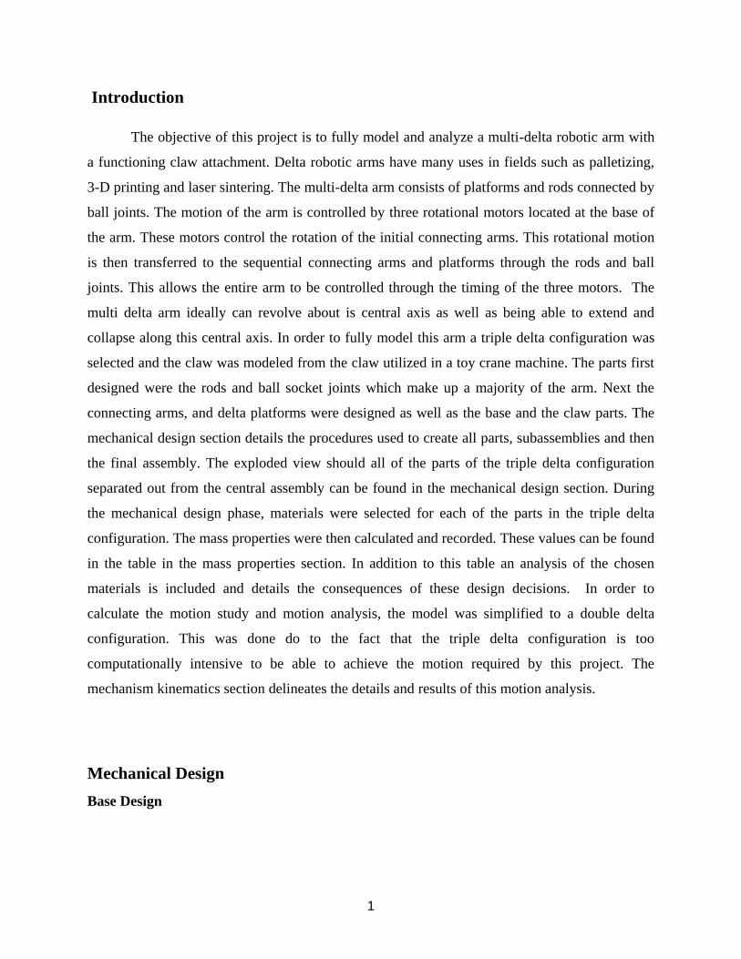
The importance of the washer is that it behaves as a preload
that maintains the tension in an assembly where some slack
may be present. This washer will eliminate any rattling
effects that can occur within the motor joint assembly. This
washer is also scaled up by a factor of 20/3.
Figure 33: Final Washer
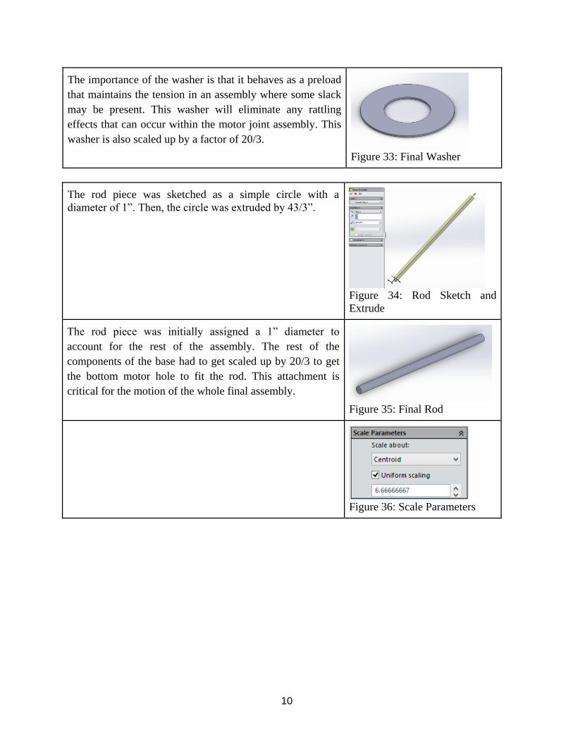
The rod piece was sketched as a simple circle with a
diameter of 1”. Then, the circle was extruded by 43/3”.
Figure 34: Rod Sketch and
Extrude
The rod piece was initially assigned a 1” diameter to
account for the rest of the assembly. The rest of the
components of the base had to get scaled up by 20/3 to get
the bottom motor hole to fit the rod. This attachment is
critical for the motion of the whole final assembly.
Figure 35: Final Rod
Figure 36: Scale Parameters

11
Claw Design
Covering Cylinder
The first component in designing a functioning claw was
the central cylinder designated by the name covering
cylinder because it covers the driving pin. This part was
created by first doing a 2-D sketch along a vertical axis on
the front plane. This sketch was dimensioned and then
revolved about that vertical axis creating the cylindrical
shape. As shown in Figure 37.
Next, the 0.25 inch holes for the retaining hex bolts were
cut extruded into the top face a depth of 0.75 inches. The
next step was to extrude cut the central hole for the driving
pin, which was done through all.
A tangential plane was created, a rectangle was extruded
normal to the plane 0.75 inches in both direction 1 and 2,
then filleted with a radius of 0.5 inches and a hole was
extrude cut to accommodate a 0.25 inch hex bolt. These
features were circularly patterned three times equally
spaced, using the top edge of the cylinder as the parameter.
This will be used to secure the arm links to this covering
cylinder. As viewed in Figure 38.
Final Part is shown in Figure 39.
Figure 37: The covering
cylinder sketch.
Figure 38: The tangential
plane and subsequent
extrude
Figure 39: Covering
Cylinder.
Driving Pin with Triangular Base
The first step taking to create this component was to
extrude a cylinder with a diameter of 0.6 inches followed
by the extrusion of a circumscribed triangle with a
diameter of 4.75 inches. The cylinder was extruded to a
depth of 4 inches and the triangle was extruded 0.7 inches.
The next step in creating the driving pin was to extrude cut

12
the slots for the claw fingers as well as creating the holes
for the linking hex bolts. The sketch for the claw finger
slot was circularly patterned to align with the three points
of the triangle and allowed for a claw finger with a
thickness of 0.5 inches. This step is shown in Figure 40.
Next, a plane was created mid-way between the inner faces
of the slots. This was used to extrude cut the 0.25 inch
holes needed to accommodate the linking bolt connecting
the claw finger to the triangular base of this driving pin.
This extrude cut was done through all and then circularly
patterned three times equally spaced using the top edge of
the cylinder as the parameter. This is displayed in Figure
41.
Countersinks were extrude cut 0.019 inches into the side of
the triangular base to allow for the use of hex bolts and
nuts. To do this another plane was created offset from the
mid plane created in the previous step and a circle was
sketched it with a diameter of 0.52 inches, which is equal
to the diameter of the head of a standard hex bolt with a
0.25 inch bolt diameter.
Final Part shown in Figure 42.
Figure 40: The extrude cut
sketch pattern.
Figure 41: Showing the
mid-plane and linking bolt
holes.
Figure 42: Driving pin with
Triangular base.
Claw Finger
This component was created by extruding a 2D sketch 0.25
inches. The sketch was created using the spline sketch tool
coupled with a tangential arc and four straight parallel
lines. The holes were made to accommodate the 0.25 inch
linking hex bolts. The distance between the holes was
established to be 2 inches. This Sketch is shown in Figure
43.
Figure 43: Claw Finger
sketch.

13
The finish the component filets with all with a radius of
0.1 inches were added to the top surface and the curved
inner surface. In addition to these filets, a chamfer was
added to the leading edge of the claw finger, 0.2 inches at
an angle of 45 degrees.
Final Part is shown in Figure 44.
Figure 44: Claw Finger.
Claw Mounting Platform
The claw mounting platform was made by first sketching
an inscribed hexagon with a diameter of 20 inches, this
was followed by the creation of a central circle and a
circularly patterned set of lines constrained by the central
circle and the inscribed hexagon. This circular pattern used
the central circle as the parameter, and equal spacing
between instances. The dimensions given to the sketch
ensure that the piece matches the delta arm platforms on
the arm portion of the overall assembly. A circle equal in
diameter to the driving pin was also added to the center of
the sketch. This sketch was extruded 2 inches. This is
displayed in Figure 45.
The next step was creating the holes for the ball joints, this
was done utilizing a circular sketch which was mirrored
about the axis of symmetry and then circularly patterned
using the central circle as the parameter. This was
followed by an extruded circle in the center of each of
these cuts. The cut extrude was a depth of 0.55 inches and
the center circles were extruded to a thickness of 0.25
inches.
The next step was to extrude cut the holes for the bolts that
will retain the claw to the platform. These holes were cut
through all and were given a diameter of 0.25. This
component was finished with chamfers along the bottom
edge, 1.1 inches at 45 degrees. This is shown in Figure 46.
Final part is shown in Figure 47.
Figure 45: The base
platform sketch for
extrusion.
Figure 46: Showing the
chamfered edges and the
ball joints locations.
Figure 47: The claw
mounting platform.

14
Arm Link
This integral component was created using a straight shot
sketch with a length of 3.72 inches which was the length
required to have the claw fingers close when the driving
pin was fully retracted. The two holes were created to
allow for the use of 0.25 inch hex bolts and nuts. The
sketch was extruded 0.2 inches.
The final part is displayed in Figure 48.
Figure 48. The Arm Link.
Arm Design
Arm Platform The Arm Platform is where all Ball Joint Sockets and
Bearing Mount-to-Platform will mounted to. This acts
as the movable structure for the arm. It starts by
sketching a “T” inside an inscribed hexagon of a
diameter of 20 in. and a 2.0 in. thick flange on the “T”.
Making a circular pattern of 3 where the “T” webs will
intersect each other at the base circle of 3 in. was done
by creating 2 construction lines from the center and
coincide ting with the base of the “T” webs and
dimensioning an angle between them at 120 degrees.
This step is crucial since it defined the design intent of
making a delta robot arm. This is all shown in Figure
49.
The arm platform sketch was then extruded 2.0 in. as
shown in Figure 50. This dimension was chosen for the
extrusion to make it equal to the flange thickness of 2.0
Figure 49: Arm platform sketch
Figure 50: Arm platform extruded

15
in.
A new sketch for the holes (each 1.5 in. diameter) were
made on the top face of the “T” flange by mirroring
and circular patterning followed by Extrude Cut of 0.55
in. deep shown in Figure 51. It is important to note that
the distance of the pairs of holes separated by a gap on
this platform must be measured and compared to with
the distance of the pair of holes at the end of the delta
arm in order for the rods that bridge the platforms are
parallel.
Pegs were then sketched at the bottom face of the holes
(each 0.5 in. diameter) and extruded 0.25 in. upward
shown in Figure 52. These pegs will be fitted into the
same diameter holes on the Ball Joint Sockets shown in
Figure 66 on page 19.
Another hole (0.75 in. diameter) was sketched at the
center on the side of the “T” flange for the Bearing
Mount-to-Platform Bolts which will hold the Bearing
Mount that will house the Bearings. It was an extrude
cut of 0.5 in as shown in Figure 53.
The next step was to mirroring the Extrude Cut feature
on the side of the “T” flange across the right plane.
This is shown in Figure 54.
The final step was to Circular Pattern in order to put
the mirrored and original Extrude Cut feature on the
side of all “T” flange. This is shown in Figure 55.
The completed part can be shown on Figure 56. Each
Arm Platform will have a total of 6 placements for the
each Ball Joint Socket that will sit on the top face of
the platform, and 6 holes for each bolt that will hold the
Bearing Mount-to-Platform. These parts will be discuss
in further detail in the next few pages.
Figure 51: Holes mirrored and
circular patterned
Figure 52: Sketch of pegs in holes
then extrude
Figure 53:Hole on side of flange
Figure 54: Mirroring holes about
right plane

16
Figure 55: Circular Patterning the
holes on “T” flange side
Figure 56: The Arm Platform
Ball Joint
The Ball Joint is the fundamental component that
allows motion for the delta robot arm to be possible. It
was first created by sketching a semicircle using a
centerline through the origin, then using 3-point arc
tool starting from the origin to a reasonable distance
away on the centerline, and making the 180 degree arc
on the other side of the centerline. The diameter of the
semicircle was 2.0 in. The Revolving feature was used
to create a sphere by revolving the semicircle about the
Figure 57: Revolving the semi-circle

17
centerline. This is shown in Figure 57.
A plane was created using the Reference Geometry
feature on the surface of the Ball Joint. The plane was
made tangent to the face of the sphere and then parallel
to the front plane (in this case). This is shown in Figure
58. This plane will be used as the sketch plane in the
next step.
On the new sketch plane, a circle of 1.0 in. was
constructed with the center being the point tangent to
the face of the sphere. This circle was then Extrude Cut
inward into the sphere at a depth of 1.0 in... This is
shown in Figure 59. This will create a hole for the rod
of the same diameter to be insert in to.
The completed Ball Joint can be shown in Figure 60.
The integral part will be assembled later with the Ball
Joint Socket and will allow the Ball Joint 3 degrees of
rotation.
Figure 58: Creating a plane
Figure 59: Extrude Cut a hole
Figure 60: The Ball Joint
Ball Joint Socket
The Ball Joint Socket was made for the purpose of the
Ball Joint to rotate freely with all degrees of rotation.
It’s created by using the sphere made in the Ball Joint
as a template as shown in Figure 57. The sphere is then
Shelled outward of a thickness of 0.1 in. This is shown
in Figure 61.
A new sketch is then made on one of the given planes;
in this case the right plane was chosen. A center point
Figure 61: Section view to display
Shelling

18
rectangle was constructed with the given constraints:
one edge of the rectangle tangent to the edge of the
sphere and two corners coincident to the edge of the
sphere as shown in Figure 62. This ensures that if the
sphere were change in dimension, the rectangle
dimensions will change with it and maintain that
similar shape. An important dimension to note about in
this sketch is the 0.25 in. offset of the rectangle edge
from the origin. This dimension will govern the
limiting angle the Ball Joint can rotate within this part
without the rod interfering with this part during the
motion study.
Then the rectangle was used as the shape to Extrude
Cut with. Both directions and though all was chosen to
complete the Extrude Cut. This is shown in Figure 63.
The Extrude Cut was made for the Ball Joint to sit in
the cavity of the Ball Joint Socket.
A plane was then constructed similar to the one made
for the Ball Joint except this time the plane had to be
parallel to the face of the newly extruded cut socket. In
this case, the front plane happened to be the plane to
make that parallel reference since the front plane was
parallel to the shelled wall of the socket. This is shown
in Figure 64.
On this new plane, a circle of a diameter of 1.5 in. was
created with the center being at the point tangent to the
sphere surface. The circle is then extruded in two
directions: the first direction was to extrude up to the
body of the socket to ensure that the extrusion doesn’t
protrude into the inside wall of the socket, and the
second direction was to extrude 0.3 in. in the opposite
direction of the first. This is shown in Figure 65. This
will create the base for the socket to mount on the top
face holes of the Arm Platform.
Lastly, a hole is created from the face of the extrude
base by sketching a circle with a diameter of 0.50 in.
and centered on the face of that extruded base. The
circle is extrude cut of a depth of 0.25 in. This is shown
in Figure 66. This hole will be where the peg on the
Arm Platform will sit in.
Figure 62: Rectangle made for
Extrude Cut
Figure 63: Extrude Cut in both
directions
Figure 64: Creating a sketch plane
Figure 65: A base mount extrusion
for the socket

19
The completed Ball Joint Socket in shown in Figure 67.
Figure 66: Extrude cut
Figure 67: Ball Joint Socket
Bearing Mount to Platform
The Bearing Mount to Platform was made to house the
Bearing with the Delta Connecting Rod. It was first
created by sketching a circle of a diameter of 1.0 in.
with the center at the origin on the front plane. Then a
new sketch is created on the top plane to draw a 3-point
arc with the center at the edge of the circle, the radius
of 1.0 in. at the center of the circle, and the angle of the
arc being 60 degrees as shown in Figure 68. The
importance of making the arc angle 60 degrees is to
ensure that the Delta Connecting Rods are aligned
which can be shown on page 24 Figure 80.
Figure 68: Sketch to Sweep
20
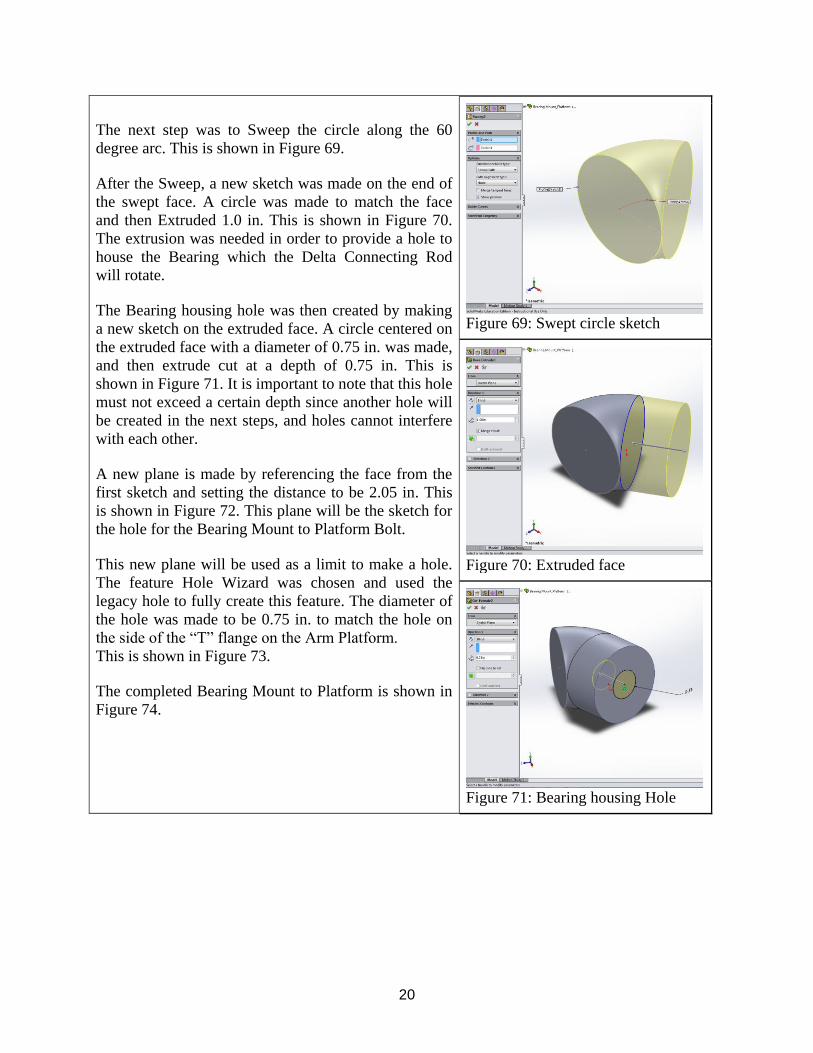
The next step was to Sweep the circle along the 60
degree arc. This is shown in Figure 69.
After the Sweep, a new sketch was made on the end of
the swept face. A circle was made to match the face
and then Extruded 1.0 in. This is shown in Figure 70.
The extrusion was needed in order to provide a hole to
house the Bearing which the Delta Connecting Rod
will rotate.
The Bearing housing hole was then created by making
a new sketch on the extruded face. A circle centered on
the extruded face with a diameter of 0.75 in. was made,
and then extrude cut at a depth of 0.75 in. This is
shown in Figure 71. It is important to note that this hole
must not exceed a certain depth since another hole will
be created in the next steps, and holes cannot interfere
with each other.
A new plane is made by referencing the face from the
first sketch and setting the distance to be 2.05 in. This
is shown in Figure 72. This plane will be the sketch for
the hole for the Bearing Mount to Platform Bolt.
This new plane will be used as a limit to make a hole.
The feature Hole Wizard was chosen and used the
legacy hole to fully create this feature. The diameter of
the hole was made to be 0.75 in. to match the hole on
the side of the “T” flange on the Arm Platform.
This is shown in Figure 73. The completed Bearing Mount to Platform is shown in
Figure 74.
Figure 69: Swept circle sketch
Figure 70: Extruded face
Figure 71: Bearing housing Hole

21
Figure 72: Creating plane
Figure 73: Sketch for hole using
Legacy Hole
Figure 74: The Bearing Mount to
Platform

22
Bearing Mount to Platform Bolt
The Bolt was made with similar dimensions to the hole
made in the last step of the Bearing Mount to Platform.
The sketch then Revolved producing the bulk of the
Bolt. Dimension can be shown in Figure 75.
A new sketch was made on the Bolt head where a slot
was made for a screwdriver can be utilized. This is
shown in Figure 76.
The completed Bearing Mount to Platform Bolt is
shown in Figure 77.
Figure 75: Sketch and Revolve Bolt
Figure 76: Slot sketch and extruded
Figure 77: Bearing Mount to
Platform Bolt
Rod
The rod is the connection between the ball joints. They
allow forces to be transferred between components.
The rod was created from an extrusion of a sketched
circle. The Rod is shown in Figure ##.
Figure 78: Rod

23
Bearing
The Bearing is the connection between the Delta
Connecting Rod and the Bearing to Platform Mount.
This bearing will allow rotation but not translation
between the rod and platform. The bearing was created
by Extruding a sketch of two circles on the sketch
plane. This component was created in class but the
radius has been modified from the one created in class.
The bearing can be seen in Figure ##.
Figure 79: Bearing
Delta Connecting Rod
The Delta Connecting Rod is the connection between
the Bearing and the Delta Arm. This is a direct
connection between the arm and the connecting rod.
Allows for rotation about the bearing in the platform.
The bearing was created by extruding on the sketch
plane for the main portion of the cylinder. Another
extrude was then created at each flat end of the rod and
extruded to the proper dimension. The Delta
Connecting Rod can be seen in Figure ##. Figure 80: Delta Connecting Rod
Delta Arm
The Delta Arm connects directly to the Delta
Connecting Rod and transfers rotation about the
Connecting Rod to translation through the Ball Joint
Socket connection. The Delta Arm was created by
extruding on the sketch plane. Extrude Cuts were then
performed on the proper planes to create the arm, hole
for the connecting rod, and connections for the ball
joint sockets. An extrude was performed on the base of
the ball joint sockets to create the second alignment
pin. The Delta Arm can be seen in Figure ## for the
Bottom and Figure ## for the Top Isometric View
Figure
81: Delta Arm (Bottom)
Figure 82: Delta Arm (TOP)

24
Bottom Delta Arm
The Bottom Delta Arm has the same principles as the
Delta Arm, only change that has been made was the
removal of the third center Ball Joint Socket
connection on the bottom of the arm. The completed
arm can be seen in Figure ##.
Figure 83: Bottom Delta Arm
(Bottom)
Driving Delta Arm
The Driving Delta Arm connects directly to the Motor
and transfers rotation about the Motor Rod to
translation through the Ball Joint Socket connection.
The Driving Delta Arm was created by extruding on
the sketch plane. Extrude Cuts were then performed on
the proper planes to create the arm, hole for the
connecting rod, and connections for the ball joint
sockets. An extrude was performed on the base of the
ball joint sockets to create the second alignment pin for
the Ball Joint Socket connections. The Driving Delta
Arm can be seen in Figure ## for the Bottom and
Figure ## for the Top Isometric View
Figure 84: Driving Delta Arm (Top)
Figure 85: Driving Delta Arm
(Bottom)
Subassemblies
Ball and Socket Joint
The Ball and Socket Joint sub assembly was created by mating
the spherical of the ball to the socket wall. This part was then
saved and used in the connection of the Rod and Joint
Assembly. An important constraint was made on this
subassembly called limiting angles which only allowed the
Ball Joint to rotate where the Rod will not cross or interfere
with the Ball Joint Socket.
Figure 86: Ball and Socket
Joint
25
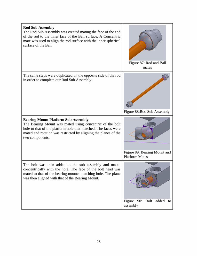
Rod Sub Assembly
The Rod Sub Assembly was created mating the face of the end
of the rod to the inner face of the Ball surface. A Concentric
mate was used to align the rod surface with the inner spherical
surface of the Ball.
Figure 87: Rod and Ball
mates
The same steps were duplicated on the opposite side of the rod
in order to complete our Rod Sub Assembly.
Figure 88:Rod Sub Assembly
Bearing Mount Platform Sub Assembly
The Bearing Mount was mated using concentric of the bolt
hole to that of the platform hole that matched. The faces were
mated and rotation was restricted by aligning the planes of the
two components.
Figure 89: Bearing Mount and
Platform Mates
The bolt was then added to the sub assembly and mated
concentrically with the hole. The face of the bolt head was
mated to that of the bearing mounts matching hole. The plane
was then aligned with that of the Bearing Mount.
Figure 90: Bolt added to
assembly

26
The mated configuration was the reflected across a plane to
match the opposite face.
Figure 91: Reflection Plane
The two completed mated configurations were then duplicated
using a circular pattern about the center of the sub assembly.
This procedure was justified due to the fact that the mounted
components are not moving components.
Figure 92: Circular Pattern
Bottom Delta Arm and Connecting Rod Sub Assembly
The Connecting Rod Sub Assembly was started by taking the
Delta Connecting Rod and the Bearing and mating them
concentrically and with the appropriate faces. The same
procedure was completed on the opposite side of the Rod.
Figure 93: Bearing to Rod
mates
The Delta Arm is added. The Delta Arm valley is mated
concentrically with the outer spherical surface of the Rod. The
Planes are also mated to that the Rod doesn’t translate in the
arm valley.
Figure 94: Delta Arm to Rod
Mates

27
The Planes of the Rod and Delta Arm are mated. The Delta
Arm and Connecting Rod Sub Assembly is complete.
Figure 95: Plane Mate
Delta Sub Assembly
The bearing from the Delta Arm and Connecting Rod Sub
Assembly is added and mated to the Platform Sub Assembly.
The Bearing is mated concentrically with the hole of the
platform bearing mount and the face of the rod is mated with
the face of the mounting bracket.
Figure 96: Bearing to
Platform Bearing Mount Mate
The Rod Sub Assembly was added and mated with the face of
the socket to the inner face of the arm. Also mated
concentrically with the arm connection hole. This step was
repeated for the other connection holes in the Delta Arm.
Figure 97: Rod Sub Assembly
to Delta Arm Mate
The Bottom Delta Sub Assembly is now complete.
Figure 98: Bottom Delta Sub
Assembly

28
Middle Delta Sub Assembly
The steps for the Middle Delta Sub Assembly are the same as
that of The Bottom Delta Sub Assembly with one more rod
added to the third connection hole of the Delta Arm.
Figure 99: Middle Delta Sub
Assembly
Top Delta Sub Assembly
The Driving Delta Arm is added to the Sub Assembly. The
Rod Sub Assembly is then added and mated concentrically
with the connection hole of the driving arm. The ball joint
socket face is mated with the inner face of the connection
hole.
Figure 100: Driving Delta
Arm
The Rod Sub Assembly is added with the same procedure for
the other connection holes for the Driving Delta Arm. The
Top Delta is now complete.
Figure 101: The Rod sub
assembly

29
The Top Delta, Middle Delta, and Bottom Delta are finally
complete. They are now assembled by mating the appropriate
Rod Socket face to the appropriate Arm Hole using concentric
and coincident mates.
Figure 102: Mates between
the Platform sub assembly
and the connecting rods and
ball and socket joints.
Final Delta Sub Assembly
This is the Final Delta Sub Assembly completed.
Figure 103: Final delta Sub
assembly
Covering cylinder and Driving Pin The claw assembly started with the insertion of the Covering
cylinder. The driving pin was then inserted and mated
concentrically between the pin of the driving pin and the
covering cylinder slot. Also the distance between the bottom
of the covering cylinder and the driving pin was constrained.
These mates are shown in Figure 104.
Figure 104: The concentric
and limiting distance mates
between the Driving Pin and
Covering Cylinder.
30
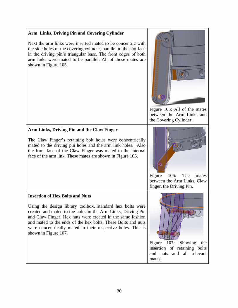
Arm Links, Driving Pin and Covering Cylinder Next the arm links were inserted mated to be concentric with
the side holes of the covering cylinder, parallel to the slot face
in the driving pin’s triangular base. The front edges of both
arm links were mated to be parallel. All of these mates are
shown in Figure 105.
Figure 105: All of the mates
between the Arm Links and
the Covering Cylinder.
Arm Links, Driving Pin and the Claw Finger The Claw Finger’s retaining bolt holes were concentrically
mated to the driving pin holes and the arm link holes. Also
the front face of the Claw Finger was mated to the internal
face of the arm link. These mates are shown in Figure 106.
Figure 106: The mates
between the Arm Links, Claw
finger, the Driving Pin.
Insertion of Hex Bolts and Nuts Using the design library toolbox, standard hex bolts were
created and mated to the holes in the Arm Links, Driving Pin
and Claw Finger. Hex nuts were created in the same fashion
and mated to the ends of the hex bolts. These Bolts and nuts
were concentrically mated to their respective holes. This is
shown in Figure 107.
Figure 107: Showing the
insertion of retaining bolts
and nuts and all relevant
mates.

31
Circular Pattern of Arm Links, Claw Finger, and Hex
bolts and nuts Circularly patterned the Arm Links, Claw Finger and retaining
nut and bolts as well as all relevant mates using the top edge
of the covering cylinder as the parameter. This is shown in
Figure 108.
Figure 108: The circular
pattern of the Nuts and Bolts,
Claw Finger, and Arm Links.
Claw Mounting platform and the Covering Cylinder Inserted the claw base platform into the assembly and mated
the top surface of the covering cylinder and the bottom surface
of the platform. And then attached the nuts utilizing the design
toolbox. This is shown in Figure 109.
Figure 109: Showing the
mates between the mounting
platform and the covering
cylinder as well as the
retaining bolts.

32
Final Claw Subassembly
Shown in Figure 110.
Figure 110: The complete
Claw subassembly.
Base Sub-Assembly
In order to produce the final base assembly, the joint
assembly steps of the motor onto the main base needs
to be repeated for the other two rectangular prisms.
This base must be capable of withstanding the
conjoined weight of the triple arm system and the
claw assembly. The scaling factor of 20/3 for all the
components of the base was convenient for the
overall assembly because the scaled version of the
assembly held the same appearance as the smaller
version. Parametric equations and configurations
would have complicated the resizing process of the
base assembly even more.
Figure 111: Final Base Sub-Assembly
First, the front face of the motor fin was made
coincident to the back face of the rectangular prism.
This mate helps eliminate some of the translational
degrees of freedom of the motor.
Figure 112: Motor Coincident Face
33
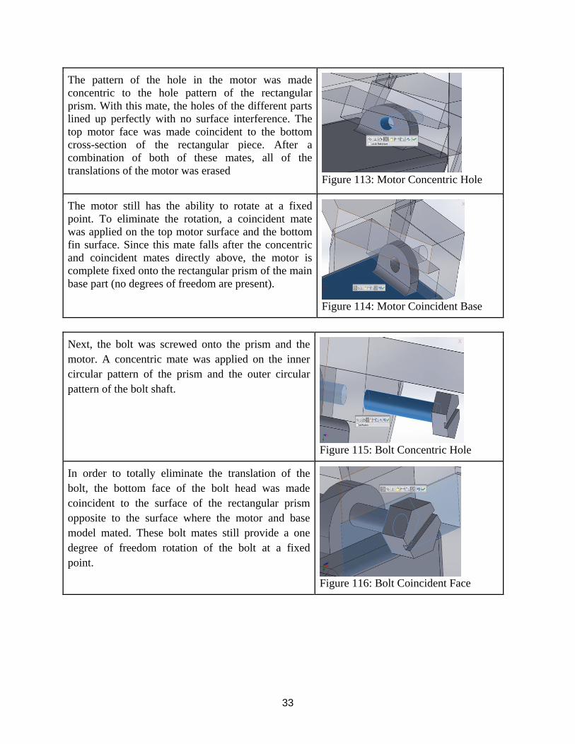
The pattern of the hole in the motor was made
concentric to the hole pattern of the rectangular
prism. With this mate, the holes of the different parts
lined up perfectly with no surface interference. The
top motor face was made coincident to the bottom
cross-section of the rectangular piece. After a
combination of both of these mates, all of the
translations of the motor was erased
Figure 113: Motor Concentric Hole
The motor still has the ability to rotate at a fixed
point. To eliminate the rotation, a coincident mate
was applied on the top motor surface and the bottom
fin surface. Since this mate falls after the concentric
and coincident mates directly above, the motor is
complete fixed onto the rectangular prism of the main
base part (no degrees of freedom are present).
Figure 114: Motor Coincident Base
Next, the bolt was screwed onto the prism and the
motor. A concentric mate was applied on the inner
circular pattern of the prism and the outer circular
pattern of the bolt shaft.
Figure 115: Bolt Concentric Hole
In order to totally eliminate the translation of the
bolt, the bottom face of the bolt head was made
coincident to the surface of the rectangular prism
opposite to the surface where the motor and base
model mated. These bolt mates still provide a one
degree of freedom rotation of the bolt at a fixed
point.
Figure 116: Bolt Coincident Face

34
After the bolt, the washer was the next component
assembled. A concentric mate was issued in along
the circular patterns of the washer and the bolt. Since
the washer hole dimension was the same as the shaft
of the bolt, the washer was able to line up evenly
with the bolt.
Figure 117: Washer Concentric Hole
Another concentric mate was used in this assembly
between the washer face and the inner face of the
motor fin. The washer was the smallest component of
entire sub-assembly.
Figure 118: Washer Coincident Face
Lastly, the nut was included in the assembly right
after the washer. The same concentric was applied
between the circular pattern of the nut and the
circular pattern of the bolt.
Figure 119: Nut Concentric Hole
The nut bottom face was made coincident to the
washer face. After these two last mates were
applied, the assembly was secured.
Figure 120: Nut Coincident Face

35
Final Triple Delta Assembly
Top Delta to Final Base Assembly
To begin the final assembly, the Top Delta is
Connected to the Base Sub Assembly. First the Rod is
mated using a concentric and coincident mate.
Figure 121: The rod mates with
motor base sub assembly
The Rod is then mated concentrically with the Driving
Delta Arm of the Top Delta Sub Assembly. It is also
mated to the appropriate planes between the Rod and
the Driving Motor Arm.
Figure 122: The coincident mate
between planes of the rod and the
motor arm.
These steps are completed for the other two motors
and Driving Delta Arms. The Top Delta subassembly
and Base assembly are now complete.
Figure 123: The Top Delta
subassembly and Base assembly

36
Bottom Delta to Final Claw Assembly
To complete this, the Bottom Delta is mated to the
Final Claw Assembly by mating concentrically and
coincidently the Rod Joint ends to the connecting holes
in the Claw assembly base.
Figure 124: Ball Socket Joint mates
with Claw Mounting Platform
This is repeated for the other four Connections. The
Delta and Claw are now fully assembled.
Figure 125: Bottom Delta and Claw
fully defined in final assembly.

37
The Triple Delta Assembly is finally complete.
Figure 126: Final Triple Delta robotic
arm configuration.

38
Exploded View of Triple Delta Configuration
Figure 127. Showing the full assembly
exploded from the front view orientation
Figure 127.
Figure 128. Shows the Arm Base and top
delta exploded from front view orientation
Figure 128
39
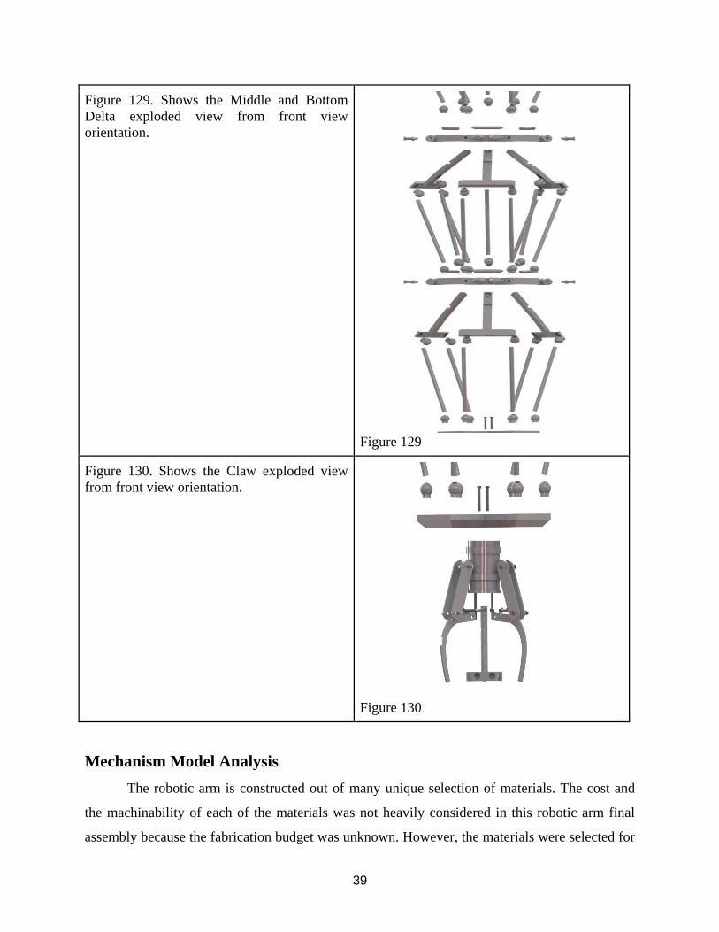
Figure 129. Shows the Middle and Bottom
Delta exploded view from front view
orientation.
Figure 129
Figure 130. Shows the Claw exploded view
from front view orientation.
Figure 130
Mechanism Model Analysis
The robotic arm is constructed out of many unique selection of materials. The cost and
the machinability of each of the materials was not heavily considered in this robotic arm final
assembly because the fabrication budget was unknown. However, the materials were selected for

40
each part based on the weight and the longevity of the components when undergoing repetitive
motion and counteracting potential stresses and strains. The essential components of the claw
were made out of steel and titanium. The base platform itself was made out of steel and the
motors were coated with plastic. Most of the rods in the whole assembly were made out of either
steel or aluminum material. The platforms for the arms were made out of steel, and the ball joints
were fabricated out of polyester resin.
After the mass properties calculations were ran in SolidWorks, it was found that the
overall mass of the robotic arm was 648.15 lbs. This is heavy robotic arm given that the total
volume of the robotic arm is only 4878.8 in3. Components such as the main base platform, the
covering cylinder of the claw, and the arm and claw mounting platform contributed significantly
to this overall weight. The rods on the bottom-top delta were keep light in weight so that the
motor connecting arm will be capable of moving the assembly up and down. The center of mass
in the 3D graphics window came out to be (-5.73, -1.65, 6.63) inches. The density of the base
was tremendous at 0.29 lbs. /in3. The moment of inertias of the final assembly and the main sub-
assemblies all were significantly heavier along the Ixx, Iyy, and Izz directions.
The best solution to alleviate any issues that can occur in the long term with the robotic
arm is to either choose lighter materials to support the volume of the final product or simply
increase the overall size of the robotic arm. Also, understanding machining cost and the
availability of materials will also be crucial in designing the most realistic arm possible.
Table I: Mass Properties of Parts
Sub-Assembly Name Mass (lbs.) Density
(cubic in.)
Material
Base Hex Bolt 1 8.20E-01 2.90E-01 AISI 304
Hex Bolt 2 8.20E-01 2.90E-01 AISI 304
Hex Bolt 3 8.20E-01 2.90E-01 AISI 304
Motor Piece 1 2.76E+01 4.00E-02 Nylon 101
Motor Piece 2 2.76E+01 4.00E-02 Nylon 101
Motor Piece 3 2.76E+01 4.00E-02 Nylon 101

41
Washer 1 0.00E+00 4.00E-02 ABS
Washer 2 0.00E+00 4.00E-02 ABS
Washer 3 0.00E+00 4.00E-02 ABS
Nut 1 1.50E-01 1.00E-01 7075-T6 (SN)
Nut 2 1.50E-01 1.00E-01 7075-T6 (SN)
Nut 3 1.50E-01 1.00E-01 7075-T6 (SN)
Rod Piece 1 3.19E+00 2.80E-01 AISI 1045 Steel, CD
Rod Piece 2 3.19E+00 2.80E-01 AISI 1045 Steel, CD
Rod Piece 3 3.19E+00 2.80E-01 AISI 1045 Steel, CD
Motor Connecting Arm 1 7.65E+00 1.00E-01 3003-H12
Motor Connecting Arm 2 7.65E+00 1.00E-01 3003-H12
Motor Connecting Arm 3 7.65E+00 1.00E-01 3003-H12
Base Final Copy 1.47E+02 2.90E-01 AISI 316 Stainless Steel
Sheet (SS)
Claw Covering Cylinder 1 5.79E+01 2.80E-02 AISI 1020 Steel, Cold
Rolled
Arm Link 1 2.00E+00 2.80E-01 AISI 4320 Steel,
normalized
Arm Link 3 2.00E+00 2.80E-01 AISI 4320 Steel,
normalized
Driving Pin/Triangle base 9.97E+00 2.80E-01 Alloy Steel
Claw Finger 1 2.03E+00 2.90E-01 AISI 321 Annealed
Stainless Steel (SS)
Claw Mounting Platform 1 4.70E+01 1.70E-01 Titanium Ti-13V-11Cr-
3Al

42
Hex Bolt_Ai 25 2.50E-01 1.60E-01 Commercially Pure
Titanium (Ti-55)
Hex Bolt_Ai 26 2.50E-01 1.60E-01 Commercially Pure
Titanium (Ti-55)
Hex Bolt_Ai 27 2.50E-01 1.60E-01 Commercially Pure
Titanium (Ti-55)
Hex Nut_Ai 16 1.00E-02 1.00E-01 7075-T6 (SN)
Hex Nut_Ai 17 1.00E-02 1.00E-01 7075-T6 (SN)
Hex Nut_Ai 19 1.00E-02 1.00E-01 7075-T6 (SN)
Hex Bolt_Ai 44 2.50E-01 1.60E-01 Commercially Pure
Titanium (Ti-55)
Hex Bolt_Ai 45 2.50E-01 1.60E-01 Commercially Pure
Titanium (Ti-55)
Hex Bolt_Ai 46 2.50E-01 1.60E-01 Commercially Pure
Titanium (Ti-55)
Hex Bolt_Ai 47 2.50E-01 1.60E-01 Commercially Pure
Titanium (Ti-55)
Top Delta Ball_Joint 1 1.40E-01 4.00E-02 Polyester Resin
Ball_Joint 2 1.40E-01 4.00E-02 Polyester Resin
Ball_Joint 3 1.40E-01 4.00E-02 Polyester Resin
Ball_Joint 4 1.40E-01 4.00E-02 Polyester Resin
Ball_Joint 5 1.40E-01 4.00E-02 Polyester Resin
Ball_Joint 6 1.40E-01 4.00E-02 Polyester Resin
Ball_Joint 33 1.40E-01 4.00E-02 Polyester Resin
Ball_Joint 34 1.40E-01 4.00E-02 Polyester Resin
Ball_Joint 35 1.40E-01 4.00E-02 Polyester Resin

43
Ball_Joint 36 1.40E-01 4.00E-02 Polyester Resin
Ball_Joint 44 1.40E-01 4.00E-02 Polyester Resin
Ball_Joint 61 1.40E-01 4.00E-02 Polyester Resin
Ball_Joint 62 1.40E-01 4.00E-02 Polyester Resin
Ball_Joint 63 1.40E-01 4.00E-02 Polyester Resin
Ball_Joint 64 1.40E-01 4.00E-02 Polyester Resin
Ball_Joint 65 1.40E-01 4.00E-02 Polyester Resin
Ball_Joint 66 1.40E-01 4.00E-02 Polyester Resin
Ball_Socket 1 4.10E-01 2.60E-01 Ductile Iron
Ball_Socket 2 4.10E-01 2.60E-01 Ductile Iron
Ball_Socket 3 4.10E-01 2.60E-01 Ductile Iron
Ball_Socket 4 4.10E-01 2.60E-01 Ductile Iron
Ball_Socket 5 4.10E-01 2.60E-01 Ductile Iron
Ball_Socket 6 4.10E-01 2.60E-01 Ductile Iron
Ball_Socket 34 4.10E-01 2.60E-01 Ductile Iron
Ball_Socket 35 4.10E-01 2.60E-01 Ductile Iron
Ball_Socket 36 4.10E-01 2.60E-01 Ductile Iron
Ball_Socket 37 4.10E-01 2.60E-01 Ductile Iron
Ball_Socket 44 4.10E-01 2.60E-01 Ductile Iron
Ball_Socket 45 4.10E-01 2.60E-01 Ductile Iron
Ball_Socket 62 4.10E-01 2.60E-01 Ductile Iron
Ball_Socket 63 4.10E-01 2.60E-01 Ductile Iron
Ball_Socket 64 4.10E-01 2.60E-01 Ductile Iron
Ball_Socket 65 4.10E-01 2.60E-01 Ductile Iron

44
Ball_Socket 66 4.10E-01 2.60E-01 Ductile Iron
Ball_Socket 67 4.10E-01 2.60E-01 Ductile Iron
Rod 1 1.55E+00 1.00E-01 3003-H14, Rod (SS)
Rod 2 1.55E+00 1.00E-01 3003-H14, Rod (SS)
Rod 3 1.55E+00 1.00E-01 3003-H14, Rod (SS)
Rod 17 1.55E+00 1.00E-01 3003-H14, Rod (SS)
Rod 18 1.55E+00 1.00E-01 3003-H14, Rod (SS)
Rod 22 1.55E+00 1.00E-01 3003-H14, Rod (SS)
Rod 31 1.55E+00 1.00E-01 3003-H14, Rod (SS)
Rod 32 1.55E+00 1.00E-01 3003-H14, Rod (SS)
Rod 33 1.55E+00 1.00E-01 3003-H14, Rod (SS)
Middle Delta Arm_Platform 1 7.12E+01 2.80E-01 AISI 1020 Steel, Cold
Rolled
Bearing Mount Platform 1 8.80E-01 1.70E-01 Titanium Ti-8Mn,
Annealed
Bearing Mount Bolt 1 1.20E-01 1.00E-01 7075-T6 (SN)
Bearing1 <1> 4.00E-02 2.90E-01 AISI 304
Bearing1 <2> 4.00E-02 2.90E-01 AISI 304
Bearing1 <9> 4.00E-02 2.90E-01 AISI 304
Bearing1 <10> 4.00E-02 2.90E-01 AISI 304
Bearing1 <17> 4.00E-02 2.90E-01 AISI 304
Bearing1 <18> 4.00E-02 2.90E-01 AISI 304
Connected Arm 1 5.19E+00 1.00E-01 7075-T6 (SN)
New Connected Rod 1 4.90E-01 1.00E-01 3003-H14

45
Connected Arm 3 5.19E+00 1.00E-01 7075-T6 (SN)
New Connected Rod 5 4.90E-01 1.00E-01 3003-H14
New Connected Rod 9 4.90E-01 1.00E-01 3003-H14
Connected Arm 4 5.19E+00 1.00E-01 7075-T6 (SN)
Ball_Joint 13 1.40E-01 4.00E-02 Polyester Resin
Ball_Joint 14 1.40E-01 4.00E-02 Polyester Resin
Ball_Joint 15 1.40E-01 4.00E-02 Polyester Resin
Ball_Joint 16 1.40E-01 4.00E-02 Polyester Resin
Ball_Joint 17 1.40E-01 4.00E-02 Polyester Resin
Ball_Joint 18 1.40E-01 4.00E-02 Polyester Resin
Ball_Joint 49 1.40E-01 4.00E-02 Polyester Resin
Ball_Joint 50 1.40E-01 4.00E-02 Polyester Resin
Ball_Joint 51 1.40E-01 4.00E-02 Polyester Resin
Ball_Joint 52 1.40E-01 4.00E-02 Polyester Resin
Ball_Joint 53 1.40E-01 4.00E-02 Polyester Resin
Ball_Joint 54 1.40E-01 4.00E-02 Polyester Resin
Ball_Joint 55 1.40E-01 4.00E-02 Polyester Resin
Ball_Joint 56 1.40E-01 4.00E-02 Polyester Resin
Ball_Joint 57 1.40E-01 4.00E-02 Polyester Resin
Ball_Joint 58 1.40E-01 4.00E-02 Polyester Resin
Ball_Joint 59 1.40E-01 4.00E-02 Polyester Resin
Ball_Joint 60 1.40E-01 4.00E-02 Polyester Resin
Ball_Socket 14 4.10E-01 2.60E-01 Ductile Iron
Ball_Socket 15 4.10E-01 2.60E-01 Ductile Iron

46
Ball_Socket 16 4.10E-01 2.60E-01 Ductile Iron
Ball_Socket 17 4.10E-01 2.60E-01 Ductile Iron
Ball_Socket 18 4.10E-01 2.60E-01 Ductile Iron
Ball_Socket 19 4.10E-01 2.60E-01 Ductile Iron
Ball_Socket 50 4.10E-01 2.60E-01 Ductile Iron
Ball_Socket 51 4.10E-01 2.60E-01 Ductile Iron
Ball_Socket 52 4.10E-01 2.60E-01 Ductile Iron
Ball_Socket 53 4.10E-01 2.60E-01 Ductile Iron
Ball_Socket 54 4.10E-01 2.60E-01 Ductile Iron
Ball_Socket 55 4.10E-01 2.60E-01 Ductile Iron
Ball_Socket 56 4.10E-01 2.60E-01 Ductile Iron
Ball_Socket 57 4.10E-01 2.60E-01 Ductile Iron
Ball_Socket 58 4.10E-01 2.60E-01 Ductile Iron
Ball_Socket 59 4.10E-01 2.60E-01 Ductile Iron
Ball_Socket 60 4.10E-01 2.60E-01 Ductile Iron
Ball_Socket 61 4.10E-01 2.60E-01 Ductile Iron
Rod 7 1.55E+00 1.00E-01 3003-H14, Rod (SS)
Rod 8 1.55E+00 1.00E-01 3003-H14, Rod (SS)
Rod 9 1.55E+00 1.00E-01 3003-H14, Rod (SS)
Rod 25 1.55E+00 1.00E-01 3003-H14, Rod (SS)
Rod 26 1.55E+00 1.00E-01 3003-H14, Rod (SS)
Rod 27 1.55E+00 1.00E-01 3003-H14, Rod (SS)
Rod 28 1.55E+00 1.00E-01 3003-H14, Rod (SS)
Rod 29 1.55E+00 1.00E-01 3003-H14, Rod (SS)

47
Rod 30 1.55E+00 1.00E-01 3003-H14, Rod (SS)
Bottom Delta Arm_Platform 1 7.12E+01 2.80E-01 AISI 1020 Steel, Cold
Rolled
Bearing Mount_Platform 1 8.80E-01 1.70E-01 Titanium Ti-8Mn,
Annealed
Bearing Mount Bolt 1 1.20E-01 1.00E-01 7075-T6 (SN)
Bottom Connecting Arm 1 4.82E+00 1.00E-01 7075-T6 (SN)
New Connecting Rod 2 4.90E-01 1.00E-01 3003-H14
Bearing1 <3> 4.00E-02 2.90E-01 AISI 304
Bearing1 <4> 4.00E-02 2.90E-01 AISI 304
Bearing1 <11> 4.00E-02 2.90E-01 AISI 304
Bearing1 <12> 4.00E-02 2.90E-01 AISI 304
Bearing1 <15> 4.00E-02 2.90E-01 AISI 304
Bearing1 <16> 4.00E-02 2.90E-01 AISI 304
New Connecting Rod 6 4.90E-01 1.00E-01 3003-H14
New Connecting Rod 8 4.90E-01 1.00E-01 3003-H14
Bottom Connecting Arm 3 4.82E+00 1.00E-01 7075-T6 (SN)
Bottom Connecting Arm 5 4.82E+00 1.00E-01 7075-T6 (SN)
Rod 35 1.55E+00 1.00E-01 3003-H14
Rod 36 1.55E+00 1.00E-01 3003-H14
Rod 37 1.55E+00 1.00E-01 3003-H14
Rod 38 1.55E+00 1.00E-01 3003-H14
Rod 39 1.55E+00 1.00E-01 3003-H14
Rod 40 1.55E+00 1.00E-01 3003-H14

48
Ball Socket 70 4.10E-01 2.60E-01 Ductile Iron
Ball Socket 71 4.10E-01 2.60E-01 Ductile Iron
Ball Socket 72 4.10E-01 2.60E-01 Ductile Iron
Ball Socket 73 4.10E-01 2.60E-01 Ductile Iron
Ball Socket 74 4.10E-01 2.60E-01 Ductile Iron
Ball Socket 75 4.10E-01 2.60E-01 Ductile Iron
Ball Socket 76 4.10E-01 2.60E-01 Ductile Iron
Ball Socket 77 4.10E-01 2.60E-01 Ductile Iron
Ball Socket 78 4.10E-01 2.60E-01 Ductile Iron
Ball Socket 79 4.10E-01 2.60E-01 Ductile Iron
Ball Socket 80 4.10E-01 2.60E-01 Ductile Iron
Ball Socket 81 4.10E-01 2.60E-01 Ductile Iron
Ball_Joint 69 1.40E-01 4.00E-02 Polyester Resin
Ball_Joint 70 1.40E-01 4.00E-02 Polyester Resin
Ball_Joint 71 1.40E-01 4.00E-02 Polyester Resin
Ball_Joint 72 1.40E-01 4.00E-02 Polyester Resin
Ball_Joint 73 1.40E-01 4.00E-02 Polyester Resin
Ball_Joint 74 1.40E-01 4.00E-02 Polyester Resin
Ball_Joint 75 1.40E-01 4.00E-02 Polyester Resin
Ball_Joint 76 1.40E-01 4.00E-02 Polyester Resin
Ball_Joint 77 1.40E-01 4.00E-02 Polyester Resin
Ball_Joint 78 1.40E-01 4.00E-02 Polyester Resin
Ball_Joint 79 1.40E-01 4.00E-02 Polyester Resin
Ball_Joint 80 1.40E-01 4.00E-02 Polyester Resin

49
Table II: Final Assembly and Subassemblies’ Mass Properties
Mass Properties of the Final Assembly
Configuration: Default
Coordinate system: -- default --
Mass = 648.15 pounds
Volume = 4878.80 cubic inches
Surface area = 10917.85 square inches
Center of mass: ( inches )
X = -5.73
Y = -1.65
Z = 6.63
Principal axes of inertia and principal
moments of inertia: ( pounds * square
inches )
Taken at the center of mass.
Ix = (-0.01, 1.00, -
0.00)
Px = 72014.42
Iy = (-0.99, -0.01,
0.13)
Py = 750120.92
Iz = (0.13, 0.00, 0.99) Pz = 750195.78
Moments of inertia: ( pounds * square
inches )
Taken at the center of mass and aligned
with the output coordinate system.
Lxx = 750098.28 Lxy = -4020.39 Lxz = 0.86
Lyx = -4020.39 Lyy = Lyz = -

50
72042.68 1730.95
Lzx = 0.86 Lzy = -1730.95 Lzz =
750190.16
Moments of inertia: ( pounds * square
inches )
Taken at the output coordinate system.
Ixx = 780354.90 Ixy = 2110.80 Ixz = -
24638.42
Iyx = 2110.80 Iyy =
121842.30
Iyz = -8820.93
Izx = -24638.42 Izy = -8820.93 Izz =
773261.68
Mass Properties of the Completed Claw
Subassembly
Configuration: Default-_flexible1
Coordinate system: -- default --
The center of mass and the moments of inertia are output in the coordinate system of
The Final Assembly
Mass = 136.31 pounds
Volume = 593.82 cubic inches
Surface area = 1537.78 square inches
Center of mass: ( inches )
X = -5.48
Y = -51.13
Z = 6.75
Principal axes of inertia and principal
moments of inertia: ( pounds * square

51
inches )
Taken at the center of mass.
Ix = (-0.00, 1.00, -
0.00)
Px = 3090.37
Iy = (-0.71, 0.00,
0.71)
Py = 4116.26
Iz = (0.71, 0.00, 0.71) Pz = 4116.26
Moments of inertia: ( pounds * square
inches )
Taken at the center of mass and aligned
with the output coordinate system.
Lxx = 4116.26 Lxy = -0.01 Lxz = -0.00
Lyx = -0.01 Lyy = 3090.37 Lyz = -2.21
Lzx = -0.00 Lzy = -2.21 Lzz = 4116.25
Moments of inertia: ( pounds * square
inches )
Taken at the output coordinate system.
Ixx = 366714.61 Ixy = 38215.89 Ixz = -5047.73
Iyx = 38215.89 Iyy = 13405.92 Iyz = -
47074.58
Izx = -5047.73 Izy = -
47074.58
Izz =
364595.09
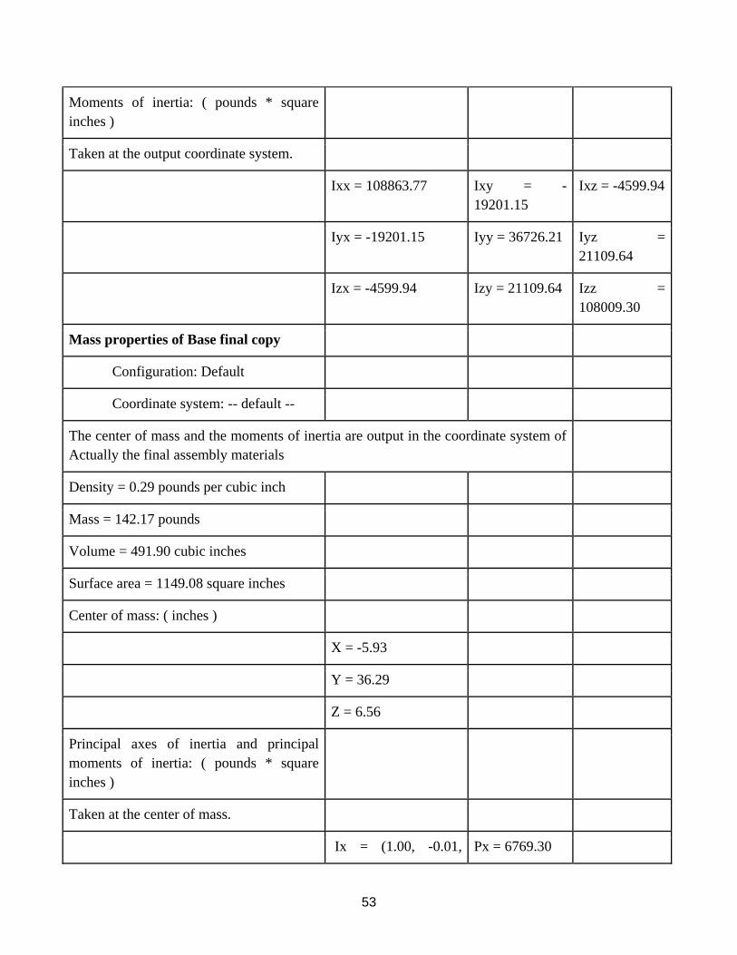
Mass properties of Base Motor Arm
Sub Assembly
Configuration: Default-_flexible1
Coordinate system: -- default --
The center of mass and the moments of inertia are output in the coordinate system of
52
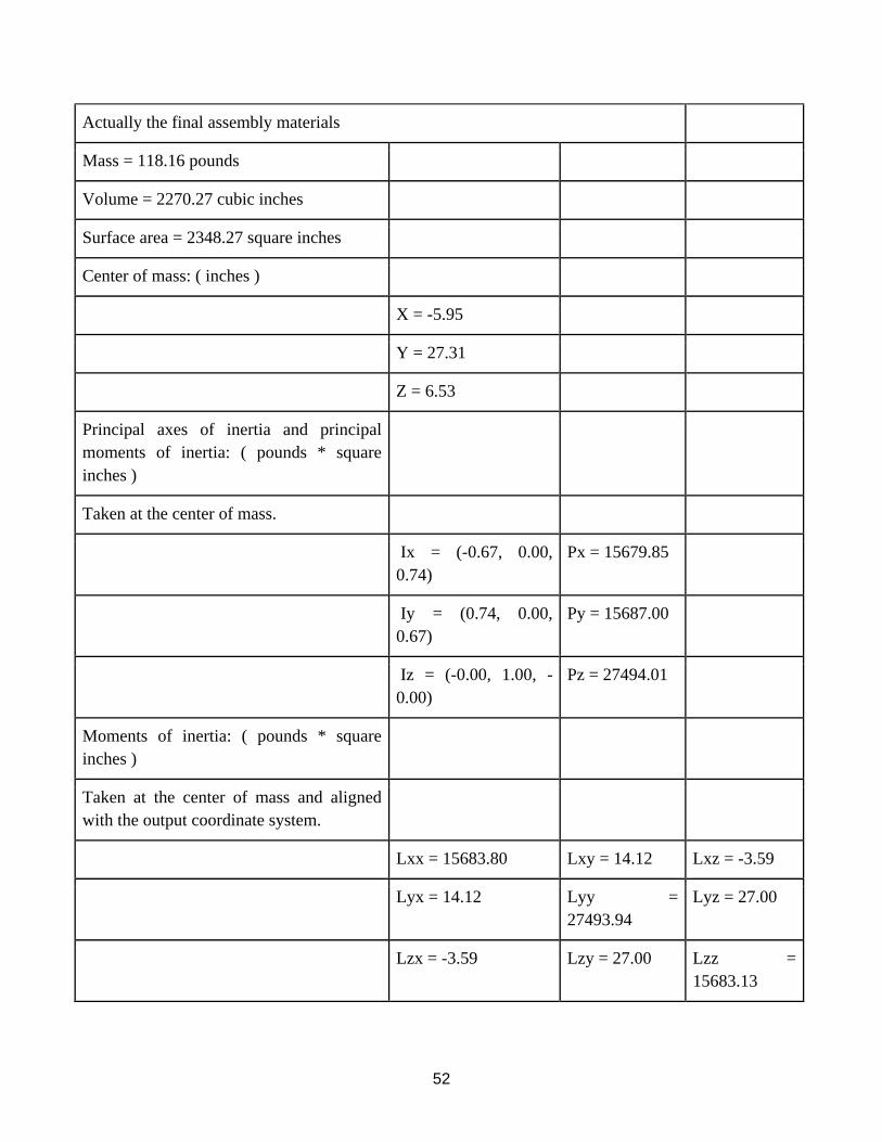
Actually the final assembly materials
Mass = 118.16 pounds
Volume = 2270.27 cubic inches
Surface area = 2348.27 square inches
Center of mass: ( inches )
X = -5.95
Y = 27.31
Z = 6.53
Principal axes of inertia and principal
moments of inertia: ( pounds * square
inches )
Taken at the center of mass.
Ix = (-0.67, 0.00,
0.74)
Px = 15679.85
Iy = (0.74, 0.00,
0.67)
Py = 15687.00
Iz = (-0.00, 1.00, -
0.00)
Pz = 27494.01
Moments of inertia: ( pounds * square
inches )
Taken at the center of mass and aligned
with the output coordinate system.
Lxx = 15683.80 Lxy = 14.12 Lxz = -3.59
Lyx = 14.12 Lyy =
27493.94
Lyz = 27.00
Lzx = -3.59 Lzy = 27.00 Lzz =
15683.13
53
Moments of inertia: ( pounds * square
inches )
Taken at the output coordinate system.
Ixx = 108863.77 Ixy = -
19201.15
Ixz = -4599.94
Iyx = -19201.15 Iyy = 36726.21 Iyz =
21109.64
Izx = -4599.94 Izy = 21109.64 Izz =
108009.30
Mass properties of Base final copy
Configuration: Default
Coordinate system: -- default --
The center of mass and the moments of inertia are output in the coordinate system of
Actually the final assembly materials
Density = 0.29 pounds per cubic inch
Mass = 142.17 pounds
Volume = 491.90 cubic inches
Surface area = 1149.08 square inches
Center of mass: ( inches )
X = -5.93
Y = 36.29
Z = 6.56
Principal axes of inertia and principal
moments of inertia: ( pounds * square
inches )
Taken at the center of mass.
Ix = (1.00, -0.01, Px = 6769.30

54
0.07)
Iy = (0.07, 0.01, -
1.00)
Py = 6844.77
Iz = (0.01, 1.00, 0.01) Pz = 11227.76
Moments of inertia: ( pounds * square
inches )
Taken at the center of mass and aligned
with the output coordinate system.
Lxx = 6769.94 Lxy = -32.76 Lxz = 5.07
Lyx = -32.76 Lyy =
11226.81
Lyz = -55.72
Lzx = 5.07 Lzy = -55.72 Lzz = 6845.08
Moments of inertia: ( pounds * square
inches )
Taken at the output coordinate system.
Ixx = 200166.27 Ixy = -
30646.26
Ixz = -5527.82
Iyx = -30646.26 Iyy = 22348.44 Iyz =
33791.88
Izx = -5527.82 Izy = 33791.88 Izz =
199128.2
Mechanism Kinematics
In order to show the movement capability of this design, a motion analysis and study was
performed. Rotational motors were added to the rotating rods in the arm base within the fully
modeled assembly. These simulate the mechanisms utilized in actual delta robotic arms. Also in
order to perform this analysis the triple delta configuration was simplified to a double delta
configuration, this significantly reduced the number mates in the assembly and made the model
much less computationally intensive. This simplification allowed analysis to be calculated
despite Central Processing Unit and Graphics Processing Unit limitations and accelerated the
study. The motor type utilized was the segment motor. This allows for control over the both the
55
distance (in degrees) the motors rotate as well as the duration of said rotation. This was
determined to be the most efficient motor type in terms of the configuration time.
The first step in demonstrating this designs ability to move in three dimensional space,
was to have the model collapse and extend along the central axis. This is done through synced
rotation of all three of the base motors. Rotating outward from the center of the base causes the
connecting arms to tilt down which extends the model. This extending motion was a set as
positive motion in the study. Rotation inward towards the center of the model causes the
connecting arms to rotate upwards collapsing the model along the central axis. This movement is
performed in the motion study from 0 seconds to 3.75 seconds
The next step in the motion analysis is to show translational motion along the plane for
which the central axis is normal. This type of motion is accomplished by inducing negative
rotation on one motor and positive rotation on the remaining two motors. This action moves the
arm along the bottom plane from the central axis toward the negatively rotating motor and away
from the positive direction of rotation. This movement is performed in the motion study from
3.75 seconds to 15.5 seconds
The final step to demonstrating the movement of the assembly was to simulate the arm’s
ability to first extend down, then actuate the claw and then finally retract up its vertical axis. This
was done to imitate the actual movement of the arm if it was being utilized to elevate an object
from a lower position to a higher position. This movement is performed in the motion study from
15.5 seconds to 21.6 seconds.
The acceleration, velocity and displacement was calculated for a point at the center of the
vertical face of the claw finger. This point was chosen due to the fact that it best tracks the
largest magnitudes of acceleration, velocity and displacement experienced by any part in the
final assembly. The following plots denoted the magnitude of these vectors in the Y direction as
the model underwent its 3-dimensional movement capability motion study.
As shown in the plots, the point undergoes dramatic changes in displacement (Plot 1),
velocity (Plot 2) and acceleration (Plot 3) as the beginning and at the end of the motion. This is
due to the fact that the study was done with respect to the y direction and at the beginning of the
study the arms capability to collapse and extend is demonstrated which will result in high
displacement, acceleration and velocity peaks in the y direction. The middle of the study
(between 4.8 seconds and 16.8 seconds) was during the demonstration of the arms ability to
move in a planar fashion and therefore the acceleration, displacement and velocity vectors
remain constant. The acceleration and velocity centers around 0 during this period of the study
which stands to reason. The final part from 16.8 seconds to 24 seconds shows the simulation of
the extending of the arm, opening and closing of the claw fingers, and the subsequent retraction

56
of the arm to finish the motion. This was done to calculate the motion of the delta arm during a
typical use cycle.
Plot 1: Linear
Displacement (y-
direction)
Plot 2: Velocity
(y-direction)
Plot 3:
Acceleration (y-
direction)
Conclusion
After modeling the parts, creating the assembly, and performing the motion study, there
are important aspects to be made. Even though the parts are very basic to model, assembling and
making the motion study were not simple to construct since assembling took many step to make
it and managing over 300 mates, and the motion study was very demanding and went through
many trial and error processes to acquire good animation. This was due to the complexity of the

57
mechanism of the multi delta configuration by which there were many ball and socket joints to
be calculated into the motion study and the fact that each ball joint had 3 degrees of rotational
freedom. The driving mechanism would only be constrained by the limiting angle set on the ball
to socket joint and the rotational extent of the motor.
58
References
[1] Dassault Systèmes - SolidWorks Corporation, 2011 “Student’s Guide to Learning
SolidWorks® Software.” PMS0119-ENG
[2] Simon, S. 2014, “Page 1,” Multi-delta robotic arm design creates large-build 3D prints in
small spaces http://www.3ders.org/articles/20141226-multi-delta-roboticarm-design-creates-
large-build-3d-prints-in- small-spaces.html (accessed Feb 24, 2015).