multi-core data streaming architecture for ray...
TRANSCRIPT

Multi-Core Data Streaming Architecture for Ray Tracing
Yoshiyuki Kaeriyama, Daichi Zaitsu,Kenichi Suzuki, Hiroaki Kobayashi
Graduate School of Information Scieneces,Tohoku University
[email protected],zaitsu,[email protected],
Nobuyuki OhbaIBM Research, Tokyo Research Laboratory,
IBM Japan, [email protected]
Abstract
Ray tracing is a computer graphics technique to gener-
ate photo-realistic images. Although it can generate precise
and realistic images, it requires a large amount of compu-
tation. The intersection test between rays and objects is one
of the dominant factors of the ray tracing speed.
We propose a new parallel processing architecture,
named RAPLAS, for accelerating the ray tracing computa-
tion. RAPLAS boosts the speed of the intersection test by us-
ing a new algorithm based on ray-casting through planes. A
data streaming architecture offers highly efficient data pro-
vision in a multi-core environment. We estimate the per-
formance of a future SoC implementation of RAPLAS by
software simulation, and show 600 times speedup over a
conventional CPU implementation.
1 Introduction
Three dimensional computer graphics is highly de-manded in many industrial and consumer electronics areas,such as architecture, automotive, aerospace, and game busi-nesses. In these areas, the quality of generated images isimportant. Ray tracing is a well known method to gener-ate photo realistic images. It is based on geometrical op-tics accurately simulating physical lighting, and illustratesspecular reflection/refraction, fuzzy reflection, shadow, andso on. Figure 1 shows our test scenes generated by ray trac-ing using an accurate soft shadow technique. Although raytracing generates photo-realistic images, it requires a largenumber of computations, which have made ray tracing beused in limited areas of computer graphics.
The intersection test between rays and objects is one ofthe factors dominating the processing speed of ray tracing.Fortunately, we can find a lot of parallelism in the intersec-
(a) Z33 (b) Bunny (c) Conference
Figure 1. Test scenes generated by ray trac-ing
tion test. The key factor for boosting the speed of intersec-tion test is to exploit plenty of parallelism. Recent GPUs[5] have high performance SIMD engines. However, theyare specialized for conventional image generation. The pro-grammability of the GPU is not enough for ray tracing, andmemory usage is also strongly limited. Therefore, it is quitedifficult to implement the processing of ray tracing onto aGPU. The GPU will not be the best solution for acceler-ating the ray tracing now and in near future. Ray tracingon a conventional CPU, equipped with multiple cores, hasbeen widely studied [8] [11]. In particular, CELL [6], whichhas multiple calculation engines providing high capabilityand flexibility, may be thought as a good candidate for theray tracing processor. However, even these CPU and CELLcannot fully exploit the huge amount of and several typesof the parallelism in the intersection test, because they areequipped with only several processor cores.
In this paper, we focus on the design of ray-tracing hard-ware. The advance in VLSI technologies makes it possibleto integrate many more functions into a single chip. Takingaccount of processing speed and power efficiency, develop-ing a new architecture and creating an SoC specialized forray tracing is the best solution to achieve ultimate perfor-
1-4244-1258-7/07/$25.00 ©2007 IEEE 171

mance of ray tracing. To fully exploit the parallelism inthe intersection test, we propose a hardware architecture,named RAPLAS (Ray tracing Architecture based on PLaneAnd Sphere intersection). We present a novel intersectiontest method using ray-plane and bounding sphere, whichcan utilize plenty of parallelism in the processing. The pro-posed architecture consists of multiple floating-point calcu-lation engines specialized for the intersection test to exploitdifferent types of the parallelism. To keep high scalabilityof the engines and low hardware cost, our architecture em-ploys a data-streaming memory system.
This paper is organized as follows. Section 2 presentsa new algorithm for the intersection test. Section 3 pro-poses a novel architecture for ray tracing. Section 4 demon-strates the efficiency of parallelization. Section 5 describesthe detailed hardware implementation. Section 6 shows theperformance estimation of the proposed architecture imple-mented as a future SoC chip. Section 7 offers concludingremarks.
2 Intersection Tests using Ray-Plane andBounding Spheres
Ray tracing shoots rays from an origin point (an eye) toan object space. A ray traverses the space until it intersectsan object. During the traverse, intersection tests betweenthe ray and objects are performed. When the closest objectblocking the ray is found, plenty of new rays to illustratevarious lighting effects such as reflection, refraction, andshadow are re-generated. To find the nearest object for ori-gin point of each ray, the intersection test between all therays and objects must be done. Therefore, the intersectiontest needs a large amount of computation.
To reduce the number of computations, a table look upmethod is often used. Before shooting a ray, approximatelocations of all the objects are calculated and stored in alocation table. By referring to the table, we can find the ob-jects that obviously do not intersect the ray, and thus we donot perform the intersection test for them. However, in caseof parallel processing which can accelerate the ray tracingdramatically, as the number of PEs (Processing Elements)increases, the accesses to the look-up table will cause a seri-ous memory contention, which decreases the PE utilization.
In a ray tracing process, a series of rays diffused from asame origin are widely used as shown in Figure 2. We havefocused on the process of the series of rays, and proposedan accelerating method of the intersection test using ray-planes and bounding spheres [2]. The principal idea of themethod is to cast ray-planes toward the grid points insteadof casting rays individually. Figure 3 shows the six steps ofthe intersection test method.
Step 1 Generate bounding spheres, each of which includes
rays from
diffuse surface
screen
rays for
light source
rays for screen
object
eye
Figure 2. Series of rays sharing same origin
ray-planebounding
sphere
object(triangle)
ray group
Figure 3. Ray-plane and sphere intersectionmethod
several triangles.
Step 2 Cast rays passing through the grid points on a cer-tain plane above the origin, even if the rays essentialityneed to cast completely random directions.
Step 3 Make a plane which includes the origin and alignedgrid points. We call it ”ray-plane”.
Step 4 By repeating Step 3 for vertical and horizontal di-rections, all the orthogonal planes are obtained.
Step 5 Perform the intersection test between the boundingspheres and all the ray-planes.
Step 6 For each bounding sphere which has intersected anytwo orthogonal planes, the intersection test are per-formed between the objects in the bounding sphere andthe original ray reproduced from the two intersectedray-planes.
Let us assume that N x N rays are cast to the space. Theconventional methods require N x N intersection tests perbounding sphere. The proposed method, on the other hand,uses planes instead of rays and requires only 2N intersectiontests per bounding sphere.
The method not only reduces the number of computa-tions but also easily exploits the parallelism residing in the
172
ray group
bounding sphere & triangle
plane
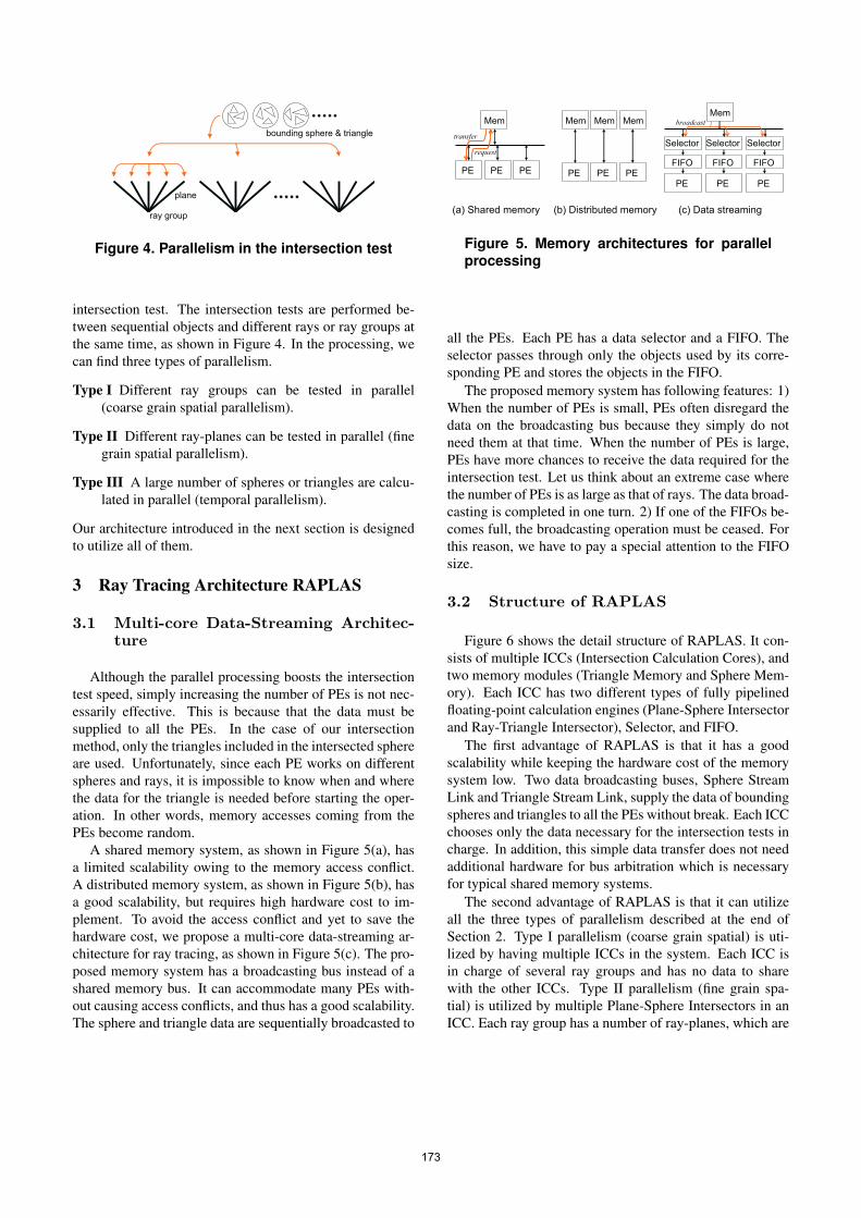
Figure 4. Parallelism in the intersection test
intersection test. The intersection tests are performed be-tween sequential objects and different rays or ray groups atthe same time, as shown in Figure 4. In the processing, wecan find three types of parallelism.
Type I Different ray groups can be tested in parallel(coarse grain spatial parallelism).
Type II Different ray-planes can be tested in parallel (finegrain spatial parallelism).
Type III A large number of spheres or triangles are calcu-lated in parallel (temporal parallelism).
Our architecture introduced in the next section is designedto utilize all of them.
3 Ray Tracing Architecture RAPLAS
3.1 Multi-core Data-Streaming Architec-ture
Although the parallel processing boosts the intersectiontest speed, simply increasing the number of PEs is not nec-essarily effective. This is because that the data must besupplied to all the PEs. In the case of our intersectionmethod, only the triangles included in the intersected sphereare used. Unfortunately, since each PE works on differentspheres and rays, it is impossible to know when and wherethe data for the triangle is needed before starting the oper-ation. In other words, memory accesses coming from thePEs become random.
A shared memory system, as shown in Figure 5(a), hasa limited scalability owing to the memory access conflict.A distributed memory system, as shown in Figure 5(b), hasa good scalability, but requires high hardware cost to im-plement. To avoid the access conflict and yet to save thehardware cost, we propose a multi-core data-streaming ar-chitecture for ray tracing, as shown in Figure 5(c). The pro-posed memory system has a broadcasting bus instead of ashared memory bus. It can accommodate many PEs with-out causing access conflicts, and thus has a good scalability.The sphere and triangle data are sequentially broadcasted to
PE
Mem
PE PE PE
Mem
PE PEPE
MemMem Mem
(a) Shared memory (b) Distributed memory (c) Data streaming
Selector
FIFO
request
transfer
broadcast
PE
Selector
FIFO
PE
Selector
FIFO
Figure 5. Memory architectures for parallelprocessing
all the PEs. Each PE has a data selector and a FIFO. Theselector passes through only the objects used by its corre-sponding PE and stores the objects in the FIFO.
The proposed memory system has following features: 1)When the number of PEs is small, PEs often disregard thedata on the broadcasting bus because they simply do notneed them at that time. When the number of PEs is large,PEs have more chances to receive the data required for theintersection test. Let us think about an extreme case wherethe number of PEs is as large as that of rays. The data broad-casting is completed in one turn. 2) If one of the FIFOs be-comes full, the broadcasting operation must be ceased. Forthis reason, we have to pay a special attention to the FIFOsize.
3.2 Structure of RAPLAS
Figure 6 shows the detail structure of RAPLAS. It con-sists of multiple ICCs (Intersection Calculation Cores), andtwo memory modules (Triangle Memory and Sphere Mem-ory). Each ICC has two different types of fully pipelinedfloating-point calculation engines (Plane-Sphere Intersectorand Ray-Triangle Intersector), Selector, and FIFO.
The first advantage of RAPLAS is that it has a goodscalability while keeping the hardware cost of the memorysystem low. Two data broadcasting buses, Sphere StreamLink and Triangle Stream Link, supply the data of boundingspheres and triangles to all the PEs without break. Each ICCchooses only the data necessary for the intersection tests incharge. In addition, this simple data transfer does not needadditional hardware for bus arbitration which is necessaryfor typical shared memory systems.
The second advantage of RAPLAS is that it can utilizeall the three types of parallelism described at the end ofSection 2. Type I parallelism (coarse grain spatial) is uti-lized by having multiple ICCs in the system. Each ICC isin charge of several ray groups and has no data to sharewith the other ICCs. Type II parallelism (fine grain spa-tial) is utilized by multiple Plane-Sphere Intersectors in anICC. Each ray group has a number of ray-planes, which are
173

Sphere Memory
Host Computer
Triangle Memory
Output Link
Sphere Stream LinkTriangle Stream Link
ICC
Ray-Triangle Intersector
Plane-Sphere Intersector
ICCICC
Selector
FIFO
Figure 6. Overview of RAPLAS
processed by Plane Sphere Intersectors in parallel. Type IIIparallelism (temporal) is utilized by the pipeline operationin the Intersectors.
At the first step of an image generation, all the data onspheres and triangles are generated by the host computer,and stored in the Triangle and Sphere Memories. In thesecond step, the sphere and triangle data are broadcastedthrough the stream links to the ICCs. Each ICCs stores thedata in its incoming FIFO and performs plane-sphere inter-section tests by using its multiple Plane-Sphere Intersectors.For any intersected spheres, the ICC performs the intersec-tion tests between the rays in the ray-planes and trianglesincluded in the sphere.
4 Implementation Details
This section describes the detail implementation ofRAPLAS. Figure 7 shows the block diagram of an acceler-ating board based on the RAPLAS architecture. The boardis compliant to a PCI form factor and supposed to be in-stalled in a PCI slot of PC. The board has a multi-core SoCcalled BUICC (BUnch of Intersection Calculation Cores)and two off-chip DRAM modules storing sphere and trian-gle data.
BUICC has a general purpose CPU core and multipleICC cores. The general purpose CPU is in charge of imagesynthesis operations other than the intersection test. TheICC consists of Plane-Sphere Intersector, Ray-Triangle In-tersector, FIFOs, Decoder, Triangle Selector, and Ray DataFetcher. The ICC shown in Figure 7 has eight Plane-SphereIntersectors and a Ray-Triangle Intersector, so that it is op-timized for the operation of 4 × 4 rays.
Plane-Sphere Intersector executes the intersection testbetween planes and bounding spheres. The Intersector cal-culates the distance between the plane and the sphere ofinterest to check whether the sphere intersects the planeor not. Triangle Selector selects the triangle data, whichare included in the intersected sphere. If it finds no inter-sected planes, the triangle data are discarded; otherwise,
Decoder
Ray-Triangle
Intersector
Ray Memory(144bit x 16)
(96bit x 1)
Triangle Selector
Triangle FIFOPlaneID FIFO
First-Triangle-ID
FIFO
Ray Data Fetcher
Decoder Table
Min-distance Memory(48bit x 16)
3129632
96
Plane Memory
1
3128
31232 48
96
3
48
5
243 48
(5bit x 16)Decoder Decoder Table
1
triangle-data
triangle-data min-tri-id
flag
plane-id
first-triangle-id
ray-data
min-tri-id min-distanceray-id
plane-idray-id
ray-data
min-tri-id
flags
3128
plane
spherePlane-Sphere Intersector
Sphere FIFO
TriangleID Memory(24bit x 16)
Output Link
Sphere Stream LinkTriangle Stream Link
PCI Bus
ICC0
ICC1
ICC2
BUICC
Accelerating Board
DRAM Module (for Sphere) DRAM Module (for Triangle)
General Purpose CPU Core
Host Computer
Figure 7. Detail block diagram of acceleratinghardware based on RAPLAS
the triangle data are written into Triangle FIFO. Ray DataFetcher reads the ray data corresponding to the plane-IDs,and inputs the ray data into Ray-Triangle Intersector. Ray-Triangle Intersector performs the intersection test of raysand triangles. After the intersection test, the triangle-IDand the distance between the intersection point and the startpoint of each ray are stored in the memory.
Plane-Sphere Intersector and Ray-Triangle Intersectorare the key components of the ICC as they directly affect thesystem performance. We designed custom-made floating-point adder and multiplier.. The Intersectors use a 24-bitfloating-point format, which we found optimal for RAPLASin terms of the speed and accuracy. We have done a lot ofsimulations and confirmed that the 24-bit format is enoughto generate images with good quality.
174

The Plane-Sphere Intersector executes the intersectiontest as follows. Given the center coordinate of sphere(cx, cy, cz), and the plane equation nxx+nyy+nzz+pw =0, the distance between the plane and the center of sphere iscalculated by:
d =¯̄nxcx + nycy + nzcz + pw
¯̄(1)
The floating-point operations for this calculation arethree additions and three multiplications. In the image syn-thesis process, to increase the throughput is more importantthan to shorten the latency. Taking this into consideration,we designed the Plane-Sphere Intersector with a 10-stagepipeline. It should be noted that this operation is to simplycheck whether the plane intersects the sphere or not. There-fore, we do not have the floating-point normalization to savethe hardware resources.
The Ray-Triangle Intersector calculates the distance be-tween the origin point and the intersection point, and calcu-lates the position of the intersection point. Let us define theray vector D and the origin of ray O. The triangle consistsof location vectors V0, V1 and V2, edge vectors E1 and E2,and normal vector E. The intersection point on the triangledefined by two barycentric coordinates u and v is calculatedby the following equation.
tuv
=1
D · E
−N · (O − V0)
(D × (O − V0) · E2)−(D × (O − V0) · E1)
(2)
When conditions u > 0, v > 0 and u+v < 1 are all met, theintersection point is positioned inside the triangle. However,division in Equation (2) requires more CPU cycles than ad-dition or multiplication. To avoid this division, we use newcondition parameters as (t′, u′, v′) = (D · E)(t, u, v). Thenew intersection conditions are defined as u′ > 0, v′ > 0and u′ + v′ < N ·D.
The floating-point operations for this calculation are 20additions and 15 multiplications. In the same way as thePlane-Sphere Intersector, we designed the Ray-Triangle In-tersector with a 25-stage pipeline.
5 Performance Evaluation
5.1 Effect of Parallelization
In order to estimate the performance of our data-streaming hardware, we did software simulations. We madea software simulator by using C++ and SystemC. We usedMicrosoft Visual C++ .Net and SystemC Version 2.0.1 forMicrosoft Windows. The simulation consists of two steps.1) A software renderer written in C++ generates profile in-formation. 2) Based on the profile information, a SystemCsimulator performs the bus-cycle accurate simulation.
Table 1. Simulation parameters# of pipes 32pipes(16+16)
# of pipeline stages 10
Latency 1
FIFO # of steps 10 / 100 / 1000
# of pipes 1pipe
# of pipeline stages 25
Latency 1
1 / 4 / 16 / 32/ 48
1sphere / 1cycle
1triangle / 1cycle
Data fetch from Sphere Memory
Data fetch from Triangle Memory
Intersection
Calculation
Core
# of Intersection Calculation Cores
Ray-Triangle
Intersector
Plane-Sphere
Intersector
Table 2. Test scenes
# of bouding spheres
# of triangles
Object
information 61828
69452
69455
Bunny Confrence
172264
344528
Z33
23638
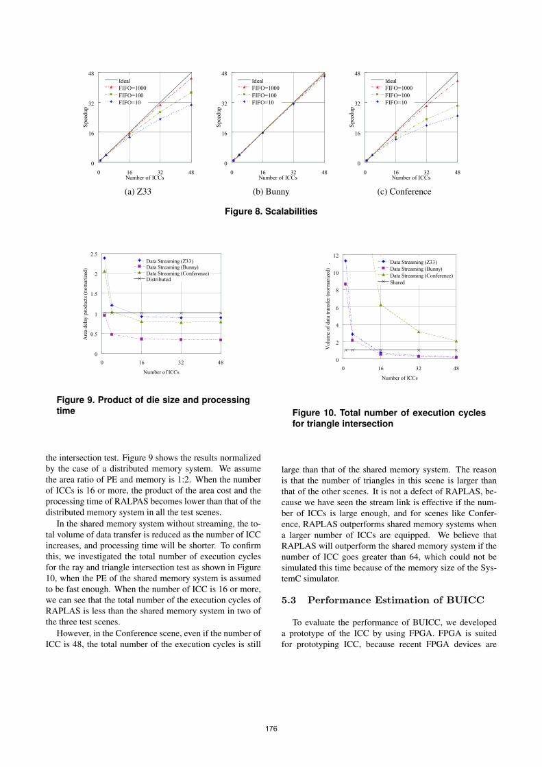
The hardware parameters for the simulation are shownin Table 1. Three images in Figure 1 and Table 2 were usedas test scenes. Image size is 64 × 64. To process 16 × 16rays in parallel, each ICC has 32 Plane-Sphere Intersectorspipelines and one Ray-Triangle Intersector. The sizes ofSphere FIFOs and Triangle FIFOs were set to 10, 100 and1,000. We investigated the total number of execution cyclesby varying the number of ICCs and FIFO size.
As shown in Figure 8, when the size of the FIFOs is1,000 (it requires several dozen KB memory for each ICC),RAPLAS achieves over 90% of scalability in all the testscenes for 48 ICCs. However, increasing the number ofICCs does not contribute to the performance when the sizeof FIFOs is 10 or 100. It is due to the FIFO full condition,which stops the object data broadcasting to all the ICCs.Based on the results, we conclude that RAPLAS can realizehighly effective parallel processing of ray tracing.
5.2 Performance Comparison with OtherData Path Designs
To show the superiorities of RAPLAS, we compare itsperformance with a shared memory system without stream-ing and a distributed memory system. The experimentalcondition is same as the previous sub-section, and the FIFOsize is assumed to be 1,000.
In the distributed memory system, the performance in-creases linearly with the number of ICCs, but the area costof memories also increases linearly. In contrast, althoughthe scalability in RAPLAS is limited as shown in Figure8, the area cost of RAPLAS increases slowly comparedwith that of the distributed memory system. To estimate thetrade-off between the area cost and performance, we calcu-late the product of the die size and the processing time for
175
0
16
32
48
0 16 32 48Number of ICCs
Sp
eed
up
Ideal
FIFO=1000
FIFO=100
FIFO=10
(a) Z33
0
16
32
48
0 16 32 48Number of ICCs
Sp
eed
up
Ideal
FIFO=1000
FIFO=100
FIFO=10
(b) Bunny
0
16
32
48
0 16 32 48Number of ICCs
Sp
eed
up
Ideal
FIFO=1000
FIFO=100
FIFO=10
(c) Conference
Figure 8. Scalabilities
0
0.5
1
1.5
2
2.5
0 16 32 48
Number of ICCs
Are
a d
elay
pro
du
cts
(no
mar
ized
) .
Data Streaming (Z33)Data Streaming (Bunny)
Data Streaming (Conference)Distributed
Figure 9. Product of die size and processingtime
the intersection test. Figure 9 shows the results normalizedby the case of a distributed memory system. We assumethe area ratio of PE and memory is 1:2. When the numberof ICCs is 16 or more, the product of the area cost and theprocessing time of RALPAS becomes lower than that of thedistributed memory system in all the test scenes.
In the shared memory system without streaming, the to-tal volume of data transfer is reduced as the number of ICCincreases, and processing time will be shorter. To confirmthis, we investigated the total number of execution cyclesfor the ray and triangle intersection test as shown in Figure10, when the PE of the shared memory system is assumedto be fast enough. When the number of ICC is 16 or more,we can see that the total number of the execution cycles ofRAPLAS is less than the shared memory system in two ofthe three test scenes.
However, in the Conference scene, even if the number ofICC is 48, the total number of the execution cycles is still
0
2
4
6
8
10
12
0 16 32 48
Number of ICCs
Vo
lum
e o
f d
ata
tran
sfer
(n
orm
ariz
ed)
. Data Streaming (Z33)
Data Streaming (Bunny)
Data Streaming (Conference)
Shared
Figure 10. Total number of execution cyclesfor triangle intersection
large than that of the shared memory system. The reasonis that the number of triangles in this scene is larger thanthat of the other scenes. It is not a defect of RAPLAS, be-cause we have seen the stream link is effective if the num-ber of ICCs is large enough, and for scenes like Confer-ence, RAPLAS outperforms shared memory systems whena larger number of ICCs are equipped. We believe thatRAPLAS will outperform the shared memory system if thenumber of ICC goes greater than 64, which could not besimulated this time because of the memory size of the Sys-temC simulator.
5.3 Performance Estimation of BUICC
To evaluate the performance of BUICC, we developeda prototype of the ICC by using FPGA. FPGA is suitedfor prototyping ICC, because recent FPGA devices are
176
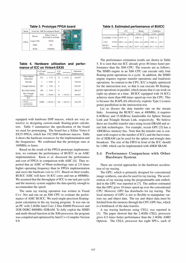
Table 3. Prototype FPGA boardBoard
DeviceXilinx Virtex-4
XC4VSX35-10 F668
Logic Cells 34510
DSPs 192
RAM 3456Kbit
Avnet Inc. MB Development Board
FPGA
Table 4. Hardware utilization and perfor-mance of ICC on Virtex4-SX35
# of Logic
Slices(utilization)
# of
DSPs(utilization)
Operation
frequency(MHz)
Plane-Sphere
Intersector872 ( 5.7% ) 12 ( 6.3% ) 164.957
Decoder 3 ( 0.0% ) 0 330.622
Triangle Selector 287 ( 1.9% ) 0 220.107
Ray Data Fetcher 588 ( 3.8% ) 0 286.217
Ray-Triangle
Intersector4726 ( 30.8% ) 70 ( 36.5% ) 164.457
ICC 8 x Plane-Sphere Intersector
+ 2 x Decoder
+ 1 x Triangle Selector
+ 1 x Ray Data Fetcher
+ 1 x Ray-Triangle Intersector
10480 ( 68.2% ) 166 ( 86.5% ) 162.339
equipped with hardware DSP macros, which are very at-tractive to designing custom-made floating-point calcula-tors. Table 3 summarizes the specification of the boardwe used for prototyping. The board has a Xilinx Virtex-4SX35 FPGA, which has 192 DSP hardware macros. Table4 shows the hardware resources for the implementation andthe frequencies. We confirmed that the prototype runs at160MHz or faster.
Based on the result of the FPGA prototype implementa-tion, we estimate the performance of BUICC in an ASICimplementation. Kuon et al. discussed the performanceand cost of FPGA in comparison with ASIC [4]. They re-ported that an ASIC of 90nm technology runs at 2.8 timeshigher operating frequency than its FPGA implementationand saves the hardware cost to 1/21. Based on their results,BUICC ASIC will have 16 ICC cores and run at 400MHz.We assumed that the throughput of ICC is one task per cycleand the memory system supplies the data quickly enough toaccommodate the speed.
The same ray tracing operation was written in VisualC++ .Net and run on an X86 CPU to evaluate the perfor-mance of ASIC BUICC. We used single-precision floating-point calculation in the ray tracing program. It was run onan PC with 2.4GHz Intel Core 2 Duo E6600 Processor and2GB DDR2 800MHz SDRAM. To fully exploit the SIMDand multi-thread function in the X86 processor, the programwas compiled and optimized by Intel C++ Compiler Version9.0.
Table 5. Estimated perfoemance of BUICC
speedup speedup speedup
Core2Duo (2.4GHz) 19.51 sec 9.68 sec 126.6 sec
1 ICC (400MHz) 482.2 msec x40.5 318.6 msec x30.4 3.599 sec x35.1
BUICC
(16 ICC)(400MHz) 30.88 msec x632 19.97 msec x484 231.3 msec x547
exe.time exe.time exe.time
Z33 Bunny Confernce
The performance estimation results are shown in Table5. It is seen that one ICC already gives 40 times faster per-formance than the X86 CPU. The reasons are as follows.The SIMD engine in an X86 CPU can execute only fourfloating-point operations in a cycle. In addition, the SIMDengine requires register transfer operations and load/storeoperations. In contrast to the CPU, ICC is highly optimizedfor the intersection test, so that it can execute 80 floating-point operations in parallel, which means that it can work oneight ray-planes at a time. BUICC equipped with 16 ICCsachieves more than 600 times speed up over the CPU. Thisis because the RAPLAS effectively exploits Type I (coarsegrain) parallelism in the intersection test.
Let us discuss the data transfer rate on the streamlinks. Assuming the BUICC runs at 400MHz, it requires6.4GB/sec and 15.6GB/sec bandwidths for Sphere StreamLink and Triangle Stream Link, respectively. We believethese are feasible transfer rates using recent DRAM and se-rial link technologies. For example, recent GPU [5] has a100GB/sec memory bus. Note that the transfer rate is con-stant with respect to the number of ICCs and the burst trans-fer of SDRAM can be used for the sphere and triangle databroadcast. The size of the FIFO in front of the ICC shouldbe 1,000, which can be implemented with 40KB SRAM.
5.4 Performance Comparison with OtherHardware System
There are several approaches in the hardware accelera-tion of ray tracing.
The GPU, which is primarily designed for conventionalimage synthesis, can also be used for ray tracing. The accel-eration of ray tracing using the programmable unit embed-ded in the GPU was reported in [7]. The authors estimatedthat the GPU gives 10 times speed up over the conventionalCPU. However, GPU has drawbacks for ray tracing. Thelocal memory of GPU is not so flexible to manipulate var-ious ray and object data. The ray and object data must befetched from the memory through the CPU-GPU bus, whichis a bottleneck of the data transfer.
A ray tracing hardware using CELL was reported in[1]. The paper showed that the 2.4GHz CELL processorgives 6.5 times better performance than the 2.4GHz AMDOpteron. The CELL processor has eight SPUs, each of
177

which has four floating-point pipelines. This configurationis not enough to fully exploit parallelism residing in the in-tersection test. In addition, a 256KB local memory for eachSPU is not large enough to sustain the ray and object data.
Several hardware architectures for ray tracing were pro-posed. Sanchez-Elez et al. presented a mapping scheme ofan optimized octree-based ray tracing algorithm and its im-plementation on a SIMD reconfigurable architecture, Mor-phoSys [9]. In addition, 3DCGiRAM integrates functionalmemories with processing elements [3]. It uses virtual 3Dintelligent memories for divided object spaces, and per-forms the ray-object intersection tests in a fully distributedmanner. However, these proposals were difficult to be ap-plied to animated scenes, because they require a recalcu-lation of the object mapping in every frame of animationscenes. In contrast, RAPLAS does not need such a recalcu-lation for dynamic scenes and can easily be applied to them.
Slusallek et al. also proposed an architecture namedSaarCor for accelerating ray tracing in [10]. The perfor-mance estimation based on a future ASIC implementationwas also reported in [12]. The authors described that thefuture ASIC implementation with eight calculation unitsrunning at 400MHz achieves approximately 80 times bet-ter performance over the conventional CPU. It requires25.6GB/sec bandwidth in the interconnection bus. Becausethe test scenes and experimental conditions are differentfrom ours, we cannot directly compare the performance ofSaarCor and RAPLAS. We think that RAPLAS has morescalability than SaarCor because of the RAPLAS memorysystem with broadcasting buses.
6 Concluding Remarks and Future Work
We have proposed a new SoC architecture namedRAPLAS for ray tracing. The RAPLAS is based on a ray-plane casting algorithm and specialized for the intersectiontest. It has fully exploited three types of parallelism in theprocessing of the plane-sphere intersection test, and kept thescalability of the calculation engine high by using broad-casting memory buses. The performance of RAPLAS hasbeen estimated by software simulations. We conclude thatRAPLAS will give a hundreds times speed up over a raytracing system using a conventional CPU.
In the near future, we will design and build ASIC versionof RAPLAS to realize real-time ray tracing animations.
Acknowledgements
The authors would like to thank to Professor Emeri-tus Tadao Nakamura, Professor Ryusuke Egawa, and Mr.Kazuhiko Komatsu of Tohoku University for their com-ments for this research. This research is partially supported
by Japan Society for the Promotion of Science, Grant-in-Aid for Scientific Research(B) 18300011.
References
[1] C. Benthin, I. Wald, M. Scherbaum, and H. Friedrich. Raytracing on the cell processor. In RT ’06: Proceedings of the
2006 IEEE Symposium on Interactive Ray Tracing, pages15–22, 2006.
[2] Y. Kaeriyama, D. Zaitsu, K. Komatsu, K. Suzuki, N. Ohba,and T. Nakamura. Hardware for a ray tracing technique us-ing plane-sphere intersections. In EGPGV ’06: Symposium
Short Paperes Proceedings of Eurographics Symposium on
Parallel Graphics and Visualization, pages 9–12, 2006.[3] H. Kobayashi, K. ichi Suzuki, K. Sano, Y. Kaeriyama,
Y. Saida, N. Oba, and T. Nakamura. 3dcgiram: An intelli-gent memory architecture for photo-realistic image synthe-sis. In ICCD ’01: Proceedings of the International Confer-
ence on Computer Design: VLSI in Computers & Proces-
sors, pages 462–467, 2001.[4] I. Kuon and J. Rose. Measuring the gap between fpgas and
asics. In FPGA ’06: Proceedings of the 2006 ACM/SIGDA
14th International Symposium on Field Programmable Gate
Arrays, pages 21–30, 2006.[5] nVIDIA. GeForce 8800, 2006. http://www.nvidia.
com/page/geforce 8800.html.[6] D. Pham, S. Asano, M. Bolliger, M. Day, H. Hofstee,
C. Johns, J. Kahle, A. Kameyama, J. Keaty, Y. Masubuchi,M. Riley, D. Shippy, D. Stasiak, M. Suzuoki, M. Wang,J. Warnock, S. Weitzel, D. Wendel, T. Yamazaki, andK. Yazawa. The design and implementation of a first-generation cell processor. In ISSCC ’05: IEEE Solid-State
Circuits Conference, 2005. Digest of Technical Papers., vol-ume 1, pages 184–592, 2005.
[7] T. J. Purcell, I. Buck, W. R. Mark, and P. Hanrahan. Raytracing on programmable graphics hardware. In SIGGRAPH
’02: Proceedings of the 29th International Conference on
Computer Graphics and Interactive Techniques, pages 703–712, 2002.
[8] A. Reshetov, A. Soupikov, and J. Hurley. Multi-level raytracing algorithm. In SIGGRAPH ’05: Proceedings of the
32nd International Conference on Computer Graphics and
Interactive Techniques, pages 1176–1185, 2005.[9] M. Sanchez-Elez, H. Du, N. Tabrizi, Y. Long,
N. Bagherzadeh, and M. Fernandez. Algorithm opti-mizations and mapping scheme for interactive ray tracingon a reconfigurable architecture. Computers & Graphics,27(5):701–713, Oct. 2003.
[10] J. Schmittler, I. Wald, and P. Slusallek. Saarcor: a hardwarearchitecture for ray tracing. In HWWS ’02: Proceedings
of the ACM SIGGRAPH/EUROGRAPHICS Conference on
Graphics Hardware, pages 27–36, 2002.[11] I. Wald, T. Ize, A. Kensler, A. Knoll, and S. G. Parker.
Ray tracing animated scenes using coherent grid traversal.25(3):485–493, 2006.
[12] S. Woop, E. Brunvand, and P. Slusallek. Estimating perfor-mance of an ray tracing asic design. In RT ’06: Proceedings
of the 2006 IEEE Symposium on Interactive Ray Tracing,pages 7–14, 2006.
178