multi-circular layout of micro/macro graphs - uni...
TRANSCRIPT
Multi-circular Layout of Micro/Macro Graphs�
Michael Baur1 and Ulrik Brandes2
1 Department of Computer Science, Universitat Karlsruhe (TH), [email protected]
2 Department of Computer & Information Science, University of Konstanz, [email protected]
Abstract. We propose a layout algorithm for micro/macro graphs, i.e.relational structures with two levels of detail. While the micro-level graphis given, the macro-level graph is induced by a given partition of themicro-level vertices. A typical example is a social network of employ-ees organized into different departments. We do not impose restrictionson the macro-level layout other than sufficient thickness of edges andvertices, so that the micro-level graph can be placed on top of the macro-level graph. For the micro-level graph we define a combinatorial multi-circular embedding and present corresponding layout algorithms basedon edge crossing reduction strategies.
1 Introduction
An important aspect in the visualization of many types of networks is the inter-play between fine- and coarse-grained structures. Think, for instance, of low-levelinteraction giving rise to emergent features at a larger scale, or people imple-menting organizational relations. Assuming that the structure on the micro levelis a graph, a macro-level graph may originate from a group-level network analysissuch as clustering or role analysis (e.g., [5]), from an attribute-based partitioningof the vertices, or may just be given in advance.
Depending on the particular application domain and other contexts, differentlayout methods will be appropriate for the macro graph. Since we only requirelarge nodes and thick edges, we assume it is given. Either the macro-level layoutalgorithm can handle varying vertex size (e.g., [12,21]) and edge thickness (e.g.,[7]), or some post-processing is applied (e.g., [11]).
Given a drawing of the macro-level graph with large nodes and thick edges,each vertex of the micro-level graph is drawn in the area defined by the macrovertex it belongs to, and each micro edge is routed through its correspondingmacro edge. We propose a multi-circular layout model for the micro graph.Each micro vertex is placed on a circle inside of the area of its correspondingmacro vertex and micro edges whose end vertices belong to the same macrovertex are drawn inside of these circles. All other micro edges are then drawninside of their corresponding macro edges and at constant but different distancesfrom the border of the macro edge, i.e. in straight-line macro edges they are� Research partially supported by DFG, grants Wa 654/13-2 and Br 2158/2-3.
S.-H. Hong, T. Nishizeki, and W. Quan (Eds.): GD 2007, LNCS 4875, pp. 255–267, 2007.c© Springer-Verlag Berlin Heidelberg 2007
256 M. Baur and U. Brandes
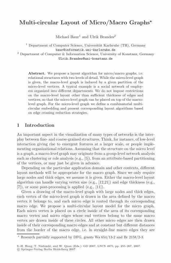
(a) geometric grouping and straight-line edges
(b) multi-circular layout
Fig. 1. (a) Example organizational network with geometric grouping and straight-lineedges (redrawn from [15]). In our multi-circular layout (b), all details are still presentand the macro structure induced by the grouping becomes visible. The height andwidth of the vertices reflects the number of connections within and between groups.
drawn as parallel lines. These edges must also be routed inside the area of macrovertices to connect to their endpoints, but are not allowed to cross the circles.In principle, an arbitrary layout strategy can be used as long as it complies withthese requirements. Figure 1 shows a concrete example of this model. Micro edgesconnecting vertices in the same macro vertex are drawn as straight lines. Insideof macro vertices, the other edges spiral around the circle of micro vertices untilthey reach the area of the macro edge. We give a combinatorial description of theabove model and then focus on the algorithmically most challenging aspect ofthese layouts, namely crossing reduction by cyclic ordering of micro vertices andchoosing edge winding within macro vertices. Finally, we apply the multi-circularlayout to an email communication network to exemplify its use case.
While the drawing convention consists of proven components (geometricgrouping is used, e.g., in [15,20], and edge routing to indicate coarse-grainedstructure is proposed in, e.g., [13,3]), our approach is novel in the way we or-ganize micro vertices to let the macro structure dominate the visual impressionwithout cluttering the micro-level details too much. Note also that the setting isvery different from layout algorithms operating on structure-induced clusterings(e.g., [14,1]), since we cannot make any assumptions on the structure of clus-ters (they may even consist of isolates). Therefore, we neither want to utilizethe clustering for better layout, nor do we want to display the segregation intodense subregions or small cuts. Our aim is to represent the interplay between a(micro-level) graph and a (most likely extrinsic) grouping of its vertices.
After defining some basic terminology in Sect. 2, we state required propertiesfor macro-graph layout in Sect. 3. Multi-circular micro-graph layout is discussedin more detail in Sect. 4 and crossing reduction algorithms for it are given inSect. 5. We conclude with an application in Sect. 6.
Multi-circular Layout of Micro/Macro Graphs 257
2 Preliminaries
Throughout this paper, let G = (V, E) be a simple undirected graph with n = |V |vertices and m = |E| edges. Furthermore, let E(v) = {{u, v} ∈ E : u ∈ V }denote the incident edges of a vertex v ∈ V , let N(v) = {u ∈ V : {u, v} ∈ E}denote its neighbors, and let sgn : R → {−1, 0, 1} be the signum function.
Since each micro-vertex is required to belong to exactly one macro-vertex,the macro structure defines a clustering, or partitioning, of the micro-vertices.Contrary to this top-down approach, we can also start from the bottom. Apartition assignment φ : V → {0, . . . , k − 1} for G subdivides the (micro-)vertexset V into k pairwise disjoint subsets V = V0∪ . . . ∪Vk−1, where Vi = {v ∈V : φ(v) = i} = φ−1(i). An edge e = {u, v} ∈ Vi× ∈ Vj is called an intra-partition edge iff i = j, otherwise it is called an inter-partition edge. The set ofintra-partition edges of a partition Vi is denoted by Ei, the set of inter-partitionedges of two partitions Vi, Vj by Ei,j . We use G = (V, E, φ) to denote a graphG = (V, E) and a related partition assignment φ.
A circular order π = {π0, . . . , πk−1} defines for each partition Vi a vertex orderπi as a bijective function πi : Vi → {0, . . . , |Vi| − 1} with u ≺ v ⇔ πi(u) < πi(v)for any two vertices u, v ∈ Vi. An order πi can be interpreted as a counter-clockwise sequence of distinct positions on the circumference of a circle.
3 Macro Layout
A prototypical macro graph, the quotient graph, is defined by a partition assign-ment. Given a partition assignment φ : V → {0, . . . , k − 1}, the correspondingquotient graph Q(G, φ) = (VQ, EQ) contains a vertex for each partition of G andtwo vertices Vi, Vj ∈ VQ are connected iff E contains at least one edge betweena vertex in Vi and a vertex in Vj .
We do not require a specific layout strategy for the macro graph as long asits elements are rendered with sufficient thickness to draw the underlying micrograph on top of them. To achieve this, post-processing can be applied to anygiven layout [11] or methods which consider vertex size (e.g., [12,21]) and edgethickness (e.g., [7]) have to be used.
From a macro layout we get partition orders Πi : VQ \Vi → {0, .., deg(Vi)−1}for each partition Vi, defined by the sequence of its incident edges in Q(G, φ),and a partition order Π = {Π0, . . . , Πk−1} for G. For each macro vertex thiscan be seen as a counter-clockwise sequence of distinct docking positions for itsincident (macro) edges on its border.
4 Micro Layout
Before we discuss the multi-circular layout model for the micro graph, let usrecall the related concepts of (single) circular and radial embeddings. In (single)circular layouts all vertices are placed on a single circle and edges are drawn as
258 M. Baur and U. Brandes
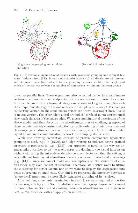
(a) some incidentedges
(b) node 4 is at po-sition 0
(c) node 4 rotatedto position 2
(d) without part-ing
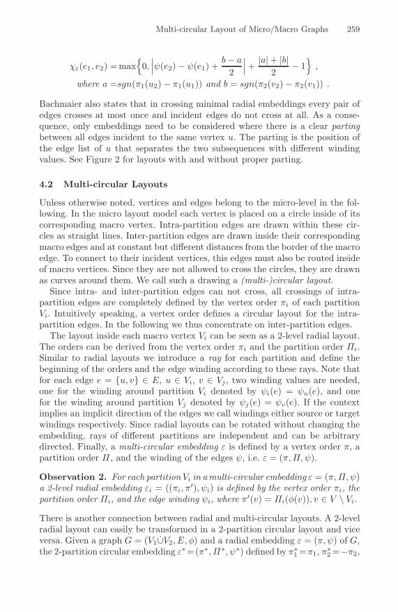
Fig. 2. Radial layouts. Edges are labeled with their winding value.
straight lines. Therefore, a (single) circular embedding ε of a graph G = (V, E)is fully defined by a vertex order π, i.e. ε = π [4]. Two edges e1, e2 ∈ E cross inε iff the end vertices of e1, e2 are encountered alternately in a cyclic traversal.
4.1 Radial Layout
In radial layouts the partitions are placed on nested concentric circles (levels)and edges are drawn as curves between consecutive partitions. Therefore, onlygraphs G = (V, E) with a proper partition assignment φ : V → {0, . . . , k − 1}are allowed, i.e. |φ(u)− φ(v)| = 1 for all edges {u, v} ∈ E. For technical reasons,edges are considered to be directed from lower to higher levels.
Recently, Bachmaier [2] investigated such layouts. They introduced a ray fromthe center to infinity to mark the start and end of the circular vertex orders.Using this ray it is also possible to count how often and in which direction anedge is wound around the common center of the circles. We call this the windingψ : E → Z of an edge (offset in [2]). |ψ(e)| counts the number of crossings of theedge with the ray and the sign reflects the mathematical direction of rotation.See Figure 2 for some illustrations. Finally, a radial embedding ε of a graphG = (V, E, φ) is defined to consist of a vertex order π and an edge winding ψ, i.e.ε = (π, ψ). Note that the rotation of a partition without permuting the verticeschanges the positions and winding values but not the number of crossings.
Crossings between edges in radial embeddings depend on their winding andon the order of the end vertices. There can be more than one crossing betweentwo edges if they have very different winding. We denote the number of crossingsbetween two edges e1, e2 ∈ E in an radial embedding ε by χε(e1, e2). The (radial)crossing number of an embedding ε and a level graph G = (V, E, φ) is thennaturally defined as χ(ε) =
∑{e1,e2}∈E,e1 �=e2
χε(e1, e2) and χ(G) = min{χ(ε) : ε
is a radial embedding of G} is called the radial crossing number of G.
Theorem 1 ([2]). Let ε = (π, ψ) be a radial embedding of a 2-level graphG = (V1∪V2, E, φ). The number of crossings χε(e1, e2) between two edges e1 =(u1, v1) ∈ E and e2 = (u2, v2) ∈ E is
Multi-circular Layout of Micro/Macro Graphs 259
χε(e1, e2) = max{
0,∣∣∣ψ(e2) − ψ(e1) +
b − a
2
∣∣∣ +
|a| + |b|2
− 1}
,
where a =sgn(π1(u2) − π1(u1)) and b = sgn(π2(v2) − π2(v1)) .
Bachmaier also states that in crossing minimal radial embeddings every pair ofedges crosses at most once and incident edges do not cross at all. As a conse-quence, only embeddings need to be considered where there is a clear partingbetween all edges incident to the same vertex u. The parting is the position ofthe edge list of u that separates the two subsequences with different windingvalues. See Figure 2 for layouts with and without proper parting.
4.2 Multi-circular Layouts
Unless otherwise noted, vertices and edges belong to the micro-level in the fol-lowing. In the micro layout model each vertex is placed on a circle inside of itscorresponding macro vertex. Intra-partition edges are drawn within these cir-cles as straight lines. Inter-partition edges are drawn inside their correspondingmacro edges and at constant but different distances from the border of the macroedge. To connect to their incident vertices, this edges must also be routed insideof macro vertices. Since they are not allowed to cross the circles, they are drawnas curves around them. We call such a drawing a (multi-)circular layout.
Since intra- and inter-partition edges can not cross, all crossings of intra-partition edges are completely defined by the vertex order πi of each partitionVi. Intuitively speaking, a vertex order defines a circular layout for the intra-partition edges. In the following we thus concentrate on inter-partition edges.
The layout inside each macro vertex Vi can be seen as a 2-level radial layout.The orders can be derived from the vertex order πi and the partition order Πi.Similar to radial layouts we introduce a ray for each partition and define thebeginning of the orders and the edge winding according to these rays. Note thatfor each edge e = {u, v} ∈ E, u ∈ Vi, v ∈ Vj , two winding values are needed,one for the winding around partition Vi denoted by ψi(e) = ψu(e), and onefor the winding around partition Vj denoted by ψj(e) = ψv(e). If the contextimplies an implicit direction of the edges we call windings either source or targetwindings respectively. Since radial layouts can be rotated without changing theembedding, rays of different partitions are independent and can be arbitrarydirected. Finally, a multi-circular embedding ε is defined by a vertex order π, apartition order Π , and the winding of the edges ψ, i.e. ε = (π, Π, ψ).
Observation 2. For each partition Vi in amulti-circular embedding ε = (π, Π, ψ)a 2-level radial embedding εi = ((πi, π
′), ψi) is defined by the vertex order πi, thepartition order Πi, and the edge winding ψi, where π′(v) = Πi(φ(v)), v ∈ V \ Vi.
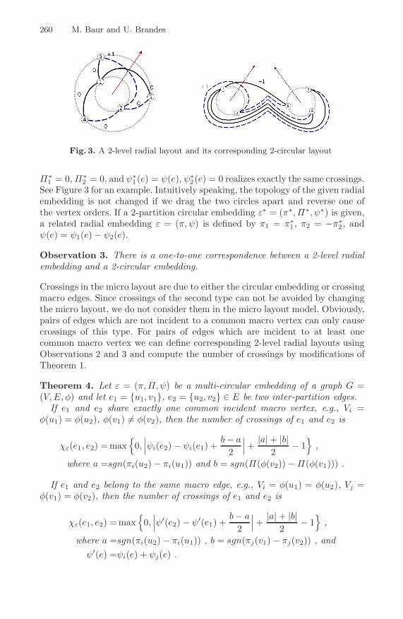
There is another connection between radial and multi-circular layouts. A 2-levelradial layout can easily be transformed in a 2-partition circular layout and viceversa. Given a graph G = (V1∪V2, E, φ) and a radial embedding ε = (π, ψ) of G,the 2-partition circular embedding ε∗=(π∗, Π∗, ψ∗) defined by π∗
1 =π1, π∗2 =−π2,
260 M. Baur and U. Brandes
Fig. 3. A 2-level radial layout and its corresponding 2-circular layout
Π∗1 = 0, Π∗
2 = 0, and ψ∗1(e) = ψ(e), ψ∗
2(e) = 0 realizes exactly the same crossings.See Figure 3 for an example. Intuitively speaking, the topology of the given radialembedding is not changed if we drag the two circles apart and reverse one ofthe vertex orders. If a 2-partition circular embedding ε∗ = (π∗, Π∗, ψ∗) is given,a related radial embedding ε = (π, ψ) is defined by π1 = π∗
1 , π2 = −π∗2 , and
ψ(e) = ψ1(e) − ψ2(e).
Observation 3. There is a one-to-one correspondence between a 2-level radialembedding and a 2-circular embedding.
Crossings in the micro layout are due to either the circular embedding or crossingmacro edges. Since crossings of the second type can not be avoided by changingthe micro layout, we do not consider them in the micro layout model. Obviously,pairs of edges which are not incident to a common macro vertex can only causecrossings of this type. For pairs of edges which are incident to at least onecommon macro vertex we can define corresponding 2-level radial layouts usingObservations 2 and 3 and compute the number of crossings by modifications ofTheorem 1.
Theorem 4. Let ε = (π, Π, ψ) be a multi-circular embedding of a graph G =(V, E, φ) and let e1 = {u1, v1}, e2 = {u2, v2} ∈ E be two inter-partition edges.
If e1 and e2 share exactly one common incident macro vertex, e.g., Vi =φ(u1) = φ(u2), φ(v1) �= φ(v2), then the number of crossings of e1 and e2 is
χε(e1, e2) =max{
0,∣∣∣ψi(e2) − ψi(e1) +
b − a
2
∣∣∣ +
|a| + |b|2
− 1}
,
where a =sgn(πi(u2) − πi(u1)) and b = sgn(Π(φ(v2)) − Π(φ(v1))) .
If e1 and e2 belong to the same macro edge, e.g., Vi = φ(u1) = φ(u2), Vj =φ(v1) = φ(v2), then the number of crossings of e1 and e2 is
χε(e1, e2) =max{
0,∣∣∣ψ′(e2) − ψ′(e1) +
b − a
2
∣∣∣ +
|a| + |b|2
− 1}
,
where a =sgn(πi(u2) − πi(u1)) , b = sgn(πj(v1) − πj(v2)) , andψ′(e) =ψi(e) + ψj(e) .
Multi-circular Layout of Micro/Macro Graphs 261
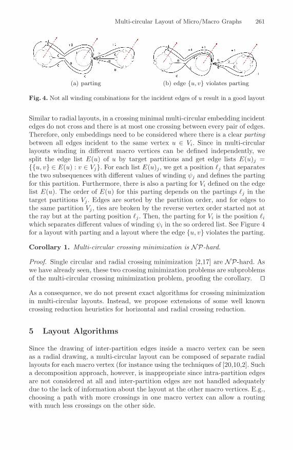
(a) parting (b) edge {u, v} violates parting
Fig. 4. Not all winding combinations for the incident edges of u result in a good layout
Similar to radial layouts, in a crossing minimal multi-circular embedding incidentedges do not cross and there is at most one crossing between every pair of edges.Therefore, only embeddings need to be considered where there is a clear partingbetween all edges incident to the same vertex u ∈ Vi. Since in multi-circularlayouts winding in different macro vertices can be defined independently, wesplit the edge list E(u) of u by target partitions and get edge lists E(u)j ={{u, v} ∈ E(u) : v ∈ Vj}. For each list E(u)j , we get a position �j that separatesthe two subsequences with different values of winding ψj and defines the partingfor this partition. Furthermore, there is also a parting for Vi defined on the edgelist E(u). The order of E(u) for this parting depends on the partings �j in thetarget partitions Vj . Edges are sorted by the partition order, and for edges tothe same partition Vj , ties are broken by the reverse vertex order started not atthe ray but at the parting position �j . Then, the parting for Vi is the position �i
which separates different values of winding ψi in the so ordered list. See Figure 4for a layout with parting and a layout where the edge {u, v} violates the parting.
Corollary 1. Multi-circular crossing minimization is NP-hard.
Proof. Single circular and radial crossing minimization [2,17] are NP-hard. Aswe have already seen, these two crossing minimization problems are subproblemsof the multi-circular crossing minimization problem, proofing the corollary. �
As a consequence, we do not present exact algorithms for crossing minimizationin multi-circular layouts. Instead, we propose extensions of some well knowncrossing reduction heuristics for horizontal and radial crossing reduction.
5 Layout Algorithms
Since the drawing of inter-partition edges inside a macro vertex can be seenas a radial drawing, a multi-circular layout can be composed of separate radiallayouts for each macro vertex (for instance using the techniques of [20,10,2]. Sucha decomposition approach, however, is inappropriate since intra-partition edgesare not considered at all and inter-partition edges are not handled adequatelydue to the lack of information about the layout at the other macro vertices. E.g.,choosing a path with more crossings in one macro vertex can allow a routingwith much less crossings on the other side.
262 M. Baur and U. Brandes
Nevertheless, we initially present in this section adaptations of radial layouttechniques because they are quite intuitive, fast, and simple, and can be usedfor the evaluation of more advanced algorithms.
5.1 Barycenter and Median Layouts
The basic idea of both the barycenter and the median layout heuristic is thefollowing: each vertex is placed in a central location computed from the positionsof its neighbors - in either the barycenter or the median position - to reduceedge lengths and hence the number of crossings. For a 2-level radial layout, theCartesian Barycenter heuristic gets the two levels and a fixed order for one ofthem. All vertices of the fixed level are set to equidistant positions on a circle andthe component-wise barycenter for all vertices of the second level is computed.The cyclic order around the center defines the order of the vertices and the edgesare routed along the geometrically shortest-path. The Cartesian Median heuristicis defined similar. Running time for both heuristics is in O(|E| + |V | log |V |).
Both heuristics are easily extended for multi-circular layouts. The layout ineach macro vertex Vi is regarded as a separate 2-level radial layout as describedin Observation 3 and the partition orders Πi are used to define the orders ofthe fixed levels. Because of the shortest-path routing, no two edges cross morethan once and incident edges do not cross at all in the final layout. On the otherhand are crossings avoided by the used placement and winding strategies onlyindirectly by edge length reduction.
5.2 Multi-circular Sifting
To overcome the drawbacks of the radial layout algorithms described before, wepropose an extension of the sifting heuristic which computes a complete multi-circular layout and considers edge crossings for optimizing both vertex order andedge winding, and thus is expected to generate better layouts.
Sifting was originally introduced as a heuristic for vertex minimization inordered binary decision diagrams [19] and later adapted for the layered one-sided, the circular, and the radial crossing minimization problems [18,4,2]. Theidea is to keep track of the objective function while moving a vertex along afixed order of all other vertices. The vertex is then placed in its (locally) optimalposition. The method is thus an extension of the greedy-switch heuristic [8]. Forcrossing reduction the objective function is the number of crossings between theedges incident to the vertex under consideration and all other edges. In multi-circular layouts this function depends on both the vertex order and the edgewinding. Therefore, we have to find for each position of a vertex the windingvalues for its incident edges which result in the minimal crossing number.
The efficient computation of crossing numbers in sifting for layered and singlecircular layouts is based on the locality of crossing changes, i.e. swapping con-secutive vertices u ↪→ v only affects crossings between edges incident to u withedges incident to v. In multi-circular layouts this property clearly holds for intra-partition edges since they form (single-)circular layouts. For inter-partition edges
Multi-circular Layout of Micro/Macro Graphs 263
the best routing path may require an update of the windings. Such a change canaffect crossings with all edges incident to the involved partitions.
Since swapping the positions of two consecutive vertices (and keeping thewinding values) only affects incident edges, the resulting change in the numberof crossings can be efficiently computed. Therefore, we need an efficient updatestrategy for edge windings while u ∈ Vi moves along the circle. We do notconsider each possible combination of windings for each position of u. but keeptrack of the parting of the edges. Note that we have to alter simultaneously theparting for the source partition and all the partings for the target partitionsbecause for an edge, a changed winding in the source partition may allow abetter routing with changed winding in the target partition. Intuitively speaking,the parting in the source partition should move around the circle in the samedirection as u, but on the opposite side of the circle, while the parting in thetarget partitions should move in the opposite direction. Otherwise, edge lengthsincrease and with it the likelihood of crossings. Thus, we start with windingvalues ψu(e) = 1 and ψv(e) = 1 for all e = {u, v} ∈ E(v) and iterativelymove parting counters around the circles and mostly decrease this values in thefollowing way:
1. First try to improve the parting at Vi, i.e. the value of ψu for the currentparting edge is decreased and the parting moved counter-clockwise to thenext edge, until this parting can no longer be improved.
2. For edges whose source winding were changed in step one, there may bebetter target windings which can not be found in step three, because thevalue of ψj has to be increased, i.e. for each affected edge, the value of ψj
for the edge is increased until no improvement is made.3. Finally try to improve the parting for each target partition Vj separately, i.e.
for each Vj the value of ψj for the current parting edge is decreased and theparting moved clockwise to the next edge, until this parting can no longerbe improved.
After each update, we ensure that all counters are valid and that winding valuesare never increased above 1 and below −1.
Based on the above, the locally optimal position of a single vertex can befound by iteratively swapping the vertex with its neighbor and updating theedge winding while keeping track of the change in crossing number. After thevertex has past each position, it is placed where the intermediary crossing countsreached their minimum. Repositioning each vertex once in this way is called around of sifting.
Theorem 5. The running time of multi-circular sifting is in O(|V | · |E|2).
Proof. Computing the difference in cross count after swapping two vertices re-quires O(|E|2) running time for one round of sifting. For each edge the windingchanges only a constant number of times because values are bounded, sourcewinding and target winding are decreased in steps one and three resp., and thetarget winding is only increased for edges whose source winding decreased be-fore. Counting the crossings of an edge after changing its winding takes time
264 M. Baur and U. Brandes
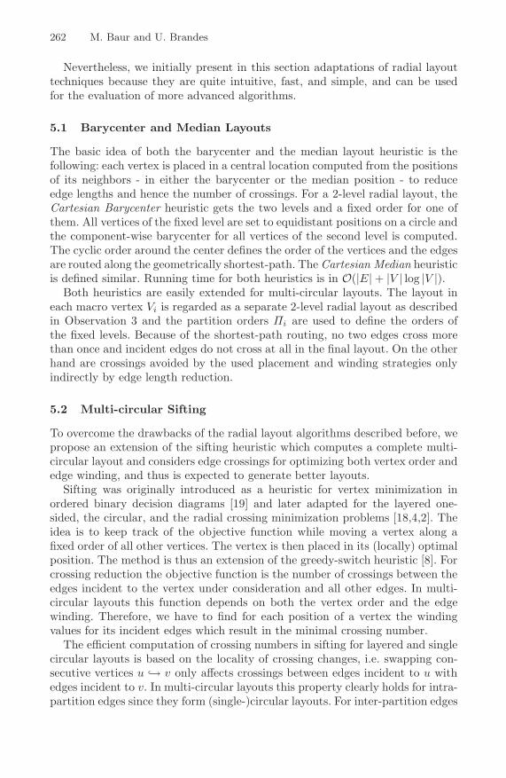
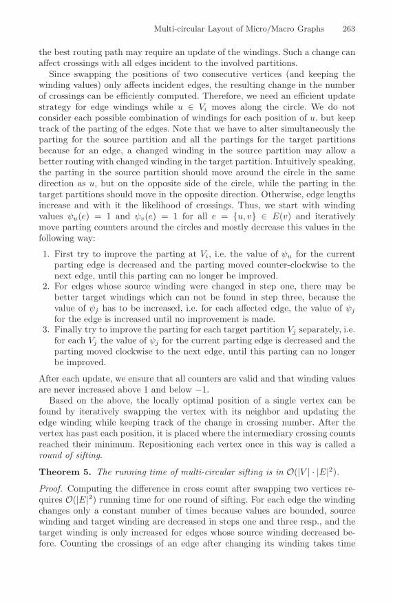
Fig. 5. Drawings of the email network generated by a force-directed method (left) andby multi-dimensional scaling (MDS, right)
O(|E|). For each vertex u ∈ V the windings are updated O(|V | · deg(u)) times,once per position and once per shifted parting. For one round, this results inO(|V ||E|) winding changes taking time O(|V | · |E|2). �
6 Application: Email Communication Network
The strength of a multi-circular layout is the coherent drawing of vertices andedges at the two levels of detail. It reveals structural properties of the macrograph and allows identification of micro level connections at the same time. Theshowcase for the benefits of our micro/macro layout is a email communicationnetwork of a department of the Universitat Karlsruhe. The micro graph consistsof 442 anonymized department members and 2,201 edges representing at leastone email communication in the considered time frame of five weeks. At themacro level, a grouping into 16 institutes is given, resulting in 66 macro edges.
We start by inspecting drawings generated by a general force-directed ap-proach similar to [9] and by multi-dimensional scaling (MDS) [6], see Figure 5.Both methods tend to place adjacent vertices near each other but ignore theadditional grouping information. Therefore, it is not surprising that the draw-ings do not show a geometric clustering and the macro structure can not beidentified. Moreover, it is difficult or even impossible to follow edges since theyoverlap each other.
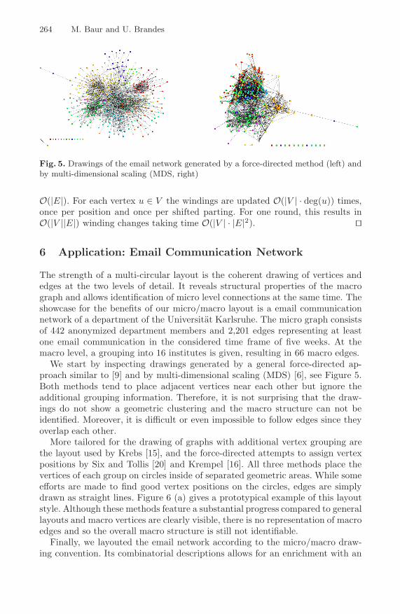
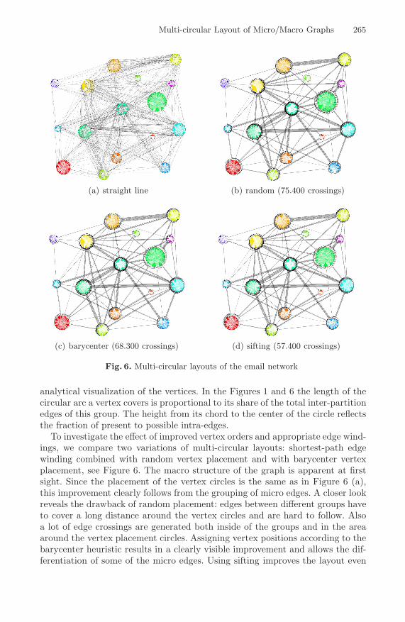
More tailored for the drawing of graphs with additional vertex grouping arethe layout used by Krebs [15], and the force-directed attempts to assign vertexpositions by Six and Tollis [20] and Krempel [16]. All three methods place thevertices of each group on circles inside of separated geometric areas. While someefforts are made to find good vertex positions on the circles, edges are simplydrawn as straight lines. Figure 6 (a) gives a prototypical example of this layoutstyle. Although these methods feature a substantial progress compared to generallayouts and macro vertices are clearly visible, there is no representation of macroedges and so the overall macro structure is still not identifiable.
Finally, we layouted the email network according to the micro/macro draw-ing convention. Its combinatorial descriptions allows for an enrichment with an
Multi-circular Layout of Micro/Macro Graphs 265
(a) straight line (b) random (75.400 crossings)
(c) barycenter (68.300 crossings) (d) sifting (57.400 crossings)
Fig. 6. Multi-circular layouts of the email network
analytical visualization of the vertices. In the Figures 1 and 6 the length of thecircular arc a vertex covers is proportional to its share of the total inter-partitionedges of this group. The height from its chord to the center of the circle reflectsthe fraction of present to possible intra-edges.
To investigate the effect of improved vertex orders and appropriate edge wind-ings, we compare two variations of multi-circular layouts: shortest-path edgewinding combined with random vertex placement and with barycenter vertexplacement, see Figure 6. The macro structure of the graph is apparent at firstsight. Since the placement of the vertex circles is the same as in Figure 6 (a),this improvement clearly follows from the grouping of micro edges. A closer lookreveals the drawback of random placement: edges between different groups haveto cover a long distance around the vertex circles and are hard to follow. Alsoa lot of edge crossings are generated both inside of the groups and in the areaaround the vertex placement circles. Assigning vertex positions according to thebarycenter heuristic results in a clearly visible improvement and allows the dif-ferentiation of some of the micro edges. Using sifting improves the layout even
266 M. Baur and U. Brandes
further, resulting from a decrease of the number of crossings from more than75.000 to 57.400 in the considered email network. The time for computing thelayout of this quiet large graph is below half a minute.
7 Conclusion
We proposed a drawing convention for micro/macro graphs where micro-levelelements are drawn on top of the elements of the coarse macro graph, so that thecontribution of micro-level elements to macro-level structure becomes apparent.Since there is no need to place restrictions on the layout of the macro graph, weassumed it is given and focused on layouts of the micro graph. We presented amulti-circular layout model and investigated layout strategies based on crossingreduction techniques for it.
Backed by the visualizations of the email communication network computedby an initial implementation of our algorithms we claim that the grouping ofmicro-edges into macro-edges according to the micro/macro drawing conventionexhibits benefits over layouts which group the vertices. Furthermore, since vertexorders and edge windings have a large effect on the readability of multi-circularlayouts, it is justified to spend a larger effort to improve them.
A major benefit of the multi-circular layout is it combinatorial descriptionsince it allows the combination with other visualization techniques to highlightsome graph properties or to further improve the visual appearance. A very in-teresting aspect would be the combination with Holten’s [13] edge bundlingtechnique.
References
1. Archambault, D., Munzner, T., Auber, D.: Topolayout: Multi-level graph layoutby topological features. IEEE Trans. Visual. and Comp. Graphics 13(2), 305–317(2007)
2. Bachmaier, C.: A radial adaptation of the sugiyama framework for visualizinghierarchical information. IEEE Trans. Visual. and Comp. Graphics 13(3), 585–594(2007)
3. Balzer, M., Deussen, O.: Level-of-detail visualization of clustered graph layouts.In: APVIS 2007. Asia-Pacific Symposium on Visualisation 2007 (2007)
4. Baur, M., Brandes, U.: Crossing reduction in circular layouts. In: Hromkovic, J.,Nagl, M., Westfechtel, B. (eds.) WG 2004. LNCS, vol. 3353, pp. 332–343. Springer,Heidelberg (2004)
5. Brandes, U., Erlebach, T. (eds.): Network Analysis. LNCS, vol. 3418. Springer,Heidelberg (2005)
6. Cox, T.F., Cox, M.A.A.: Multidimensional Scaling. In: Monographs on Statisticsand Applied Probability, 2nd edn., Chapman & Hall/CRC (2001)
7. Duncan, C.A., Efrat, A., Kobourov, S.G., Wenk, C.: Drawing with fat edges. In:Mutzel, P., Junger, M., Leipert, S. (eds.) GD 2001. LNCS, vol. 2265, pp. 162–177.Springer, Heidelberg (2002)
8. Eades, P., Kelly, D.: Heuristics for reducing crossings in 2-layered networks. ArsCombinatoria 21(A), 89–98 (1986)
Multi-circular Layout of Micro/Macro Graphs 267
9. Fruchterman, T.M.J., Reingold, E.M.: Graph drawing by force-directed placement.Software - Practice and Experience 21(11), 1129–1164 (1991)
10. Gansner, E.R., Koren, Y.: Improved circular layouts. In: Kaufmann, M., Wagner,D. (eds.) GD 2006. LNCS, vol. 4372, pp. 386–398. Springer, Heidelberg (2007)
11. Gansner, E.R., North, S.C.: Improved force-directed layouts. In: Whitesides, S.H.(ed.) GD 1998. LNCS, vol. 1547, pp. 364–373. Springer, Heidelberg (1999)
12. Harel, D., Koren, Y.: Drawing graphs with non-uniform vertices. In: AVI 2002.Proc. Work. Conf. on Advanced Visual Interfaces, pp. 157–166. ACM Press, NewYork (2002)
13. Holten, D.: Hierarchical edge bundles: Visualization of adjacency relations in hier-archical data. IEEE Trans. Visual. and Comp. Graphics 12(5), 741–748 (2006)
14. Kaufmann, M., Wiese, R.: Maintaining the mental map for circular drawings. In:Goodrich, M.T., Kobourov, S.G. (eds.) GD 2002. LNCS, vol. 2528, pp. 12–22.Springer, Heidelberg (2002)
15. Krebs, V.E.: Visualizing human networks. Release 1.0, pp. 1–25 (February 1996)16. Krempel, L.: Visualisierung komplexer Strukturen. Grundlagen der Darstellung
mehrdimensionaler Netzwerke. Campus (2005)17. Masuda, S., Kashiwabara, T., Nakajima, K., Fujisawa, T.: On the NP-
completeness of a computer network layout problem. In: Proc. 20th IEEE Int.Symposium on Circuits and Systems 1987, pp. 292–295 (1987)
18. Matuszewski, C., Schonfeld, R., Molitor, P.: Using sifting for k-layer straightlinecrossing minimization. In: Kratochvıl, J. (ed.) GD 1999. LNCS, vol. 1731, pp. 217–224. Springer, Heidelberg (1999)
19. Rudell, R.: Dynamic variable ordering for ordered binary decision diagrams. In:Proc. IEEE/ACM Conf. Computer-Aided Design, pp. 42–47. IEEE Society, LosAlamitos (1993)
20. Six, J.M., Tollis, I.G.: A framework for user-grouped circular drawings. In: Liotta,G. (ed.) GD 2003. LNCS, vol. 2912, pp. 135–146. Springer, Heidelberg (2004)
21. Wang, X., Miyamoto, I.: Generating customized layouts. In: Brandenburg, F.J.(ed.) GD 1995. LNCS, vol. 1027, pp. 504–515. Springer, Heidelberg (1996)