multi channel lmg500 power meter - zes zimmer · test certification x x x x zes zimmer electronic...
TRANSCRIPT

Multi Channel LMG500Power Meter
User manual
Status: 2011/03/09


© Copyright 2011
ZES ZIMMER Electronic Systems GmbH
Tabaksmühlenweg 30
D-61440 Oberursel (Taunus), FRG
phone ++49 (0)6171 628750
fax ++49 (0)6171 52086
e-mail: [email protected]
ZES ZIMMER Inc.
44 Grandville Ave. SW; Suite 360
Grand Rapids, MI 49503, USA
phone +1 760 550 9371
e-mail: [email protected]
Internet: http://www.zes.com
No part of this document may be reproduced, in any form or by any means, without the
permission in writing from ZES ZIMMER Electronic Systems GmbH.
Regard DIN 34!
We reserve the right to implement technical changes at any time, particularly where these
changes will improve the performance of the instrument.


Test Certification
x x
x x
ZES ZIMMER Electronic Systems GmbH certifies the above instrument to comply withall specifications contained in the delivered user manual. It has left the factory inmechanically and electrically safe condition.
The measuring instruments, tools and standards used in production, adjustment andcalibration are calibrated according to ISO9000 (traceable to national standards) andcorrespond to the standard of precision required to maintain the specified accuracies.
Date Tabaksmühlenweg 30D-61440 Oberursel
Germany
Quality Control

Request/order for a calibration
Instrument: LMG90 LMG95 LMG310
LMG450 LMG500 other:
Serial number:
For the above instrument the following should be done:
Calibration
(order-no KR-xxx)
Adjustment with following
calibration (order-no JKR-xxx)
Input calibration, adjustment and
output calibration (order-no KJKR-xxx)
I don’t want to get the latest software in the instrument (free of charge). I want to keep the
actual implemented software version.
Note:
Calibration is only to proof the differences between the instrument and the ‘true’ values
Adjustment is to set-up an instrument to meet its specifications.
Company :
Street :
ZIP/City :
Country :
Email :
Name (responsible for
calibration) :
Phone :
Fax :
Department :
Customer number (if available):
Date: Sign:
Please send this paper via post or fax to:
Z E S ZIMMER Electronic Systems GmbH Tel. +49 (0)6171/628750
Tabaksmühlenweg 30 Fax +49 (0)6171/52086
D-61440 Oberursel Email [email protected]
Germany


11
Table of contents
1 Instructions and Warnings................................................................191.1 Safety Instructions..................................................................................... 19
2 General..............................................................................................232.1 Features and application areas .................................................................. 232.2 Usage of the manual.................................................................................. 242.3 General handling of the instrument .......................................................... 252.4 The group concept..................................................................................... 272.5 Linked values, star to delta conversion (option L50-O6) ........................ 332.6 More than 4 power measuring channels ................................................... 37
3 Installation ........................................................................................453.1 Unpacking and putting into operation ...................................................... 453.2 General set-up ........................................................................................... 453.3 Connections of the LMG500 .................................................................... 45
3.3.1 Measuring circuit for typical line applications using the internal current path...... 463.3.2 Measuring circuit for measuring efficiency of 3/1phase systems .......................... 473.3.3 Measuring circuit (typical) for star to delta conversion (option L50-O6).............. 483.3.4 Aron wiring............................................................................................................ 493.3.5 Measuring circuit for measuring efficiency of 3/3phase systems .......................... 503.3.6 Measuring circuit using an external current sensor ............................................... 503.3.7 Measurements at middle and high voltage systems ............................................... 513.3.8 Measurements at middle and high voltage systems without N.............................. 523.3.9 Measurements at middle and high voltage systems without N.............................. 53
3.4 Coupling of two LMG500 (L50-Z13) for a 8 channel instrument........... 53
4 Instrument controls ...........................................................................554.1 Front panel ................................................................................................ 554.2 Rear panel.................................................................................................. 564.3 Display ...................................................................................................... 59
4.3.1 Status line............................................................................................................... 594.4 General menues......................................................................................... 60
4.4.1 Misc. ...................................................................................................................... 604.4.2 IF/IO....................................................................................................................... 614.4.3 Custom menu ......................................................................................................... 674.4.4 Script/Formula editor............................................................................................. 694.4.5 Saving and restoring configurations ...................................................................... 79
4.5 Entering identifiers, characters and text ................................................... 794.6 Entering numerical values.........................................................................84
5 Normal measuring mode...................................................................855.1 Measuring configuration (Measuring)...................................................... 85
5.1.1 Globals tab ............................................................................................................. 85
12
5.1.2 Group A/B/C/D tab................................................................................................ 865.1.3 Ev. AB/CD tab (option L50-O5) ........................................................................... 87
5.2 Measuring ranges (Range) ........................................................................ 885.2.1 Group A/B tab........................................................................................................ 895.2.2 Sense/More tab ...................................................................................................... 905.2.3 Delay...................................................................................................................... 90
5.3 Definition of measuring values................................................................. 915.3.1 More than 4 power measuring channels ................................................................ 965.3.2 Values from single measuring ............................................................................. 1005.3.3 Integrated values .................................................................................................. 1015.3.4 Total values.......................................................................................................... 102
5.4 Display of values..................................................................................... 1035.4.1 Default ................................................................................................................. 1055.4.2 Voltage................................................................................................................. 1055.4.3 Current ................................................................................................................. 1055.4.4 Power ................................................................................................................... 1065.4.5 Energy.................................................................................................................. 1065.4.6 Graphical display ................................................................................................. 1075.4.7 Custom menu ....................................................................................................... 112
5.5 Storage of values..................................................................................... 112
6 CE-Harmonic measuring mode (option L50-O9)...........................1136.1 Measuring configuration (Measuring).................................................... 113
6.1.1 Global tab............................................................................................................. 1136.1.2 Group A/B tab...................................................................................................... 114
6.2 Measuring ranges (Range) ...................................................................... 1156.3 Definition of measuring values............................................................... 1156.4 Display of values..................................................................................... 116
6.4.1 Default ................................................................................................................. 1176.4.2 Voltage................................................................................................................. 1176.4.3 Current ................................................................................................................. 1176.4.4 Power ................................................................................................................... 1186.4.5 Long time evaluation ........................................................................................... 1186.4.6 Graphical display ................................................................................................. 1196.4.7 Custom menu ....................................................................................................... 121
6.5 Storage of values..................................................................................... 1216.6 Compliance tests according EN61000-3-2 ............................................. 121
7 CE-Flicker measuring mode (option L50-O4) ...............................1237.1 Measuring configuration (Measuring).................................................... 123
7.1.1 Globals tab ........................................................................................................... 1237.1.2 Ztest/Zref tab........................................................................................................ 124
7.2 Measuring ranges (Range) ...................................................................... 1247.3 Definition of measuring values............................................................... 1247.4 Display of values..................................................................................... 125
7.4.1 Default ................................................................................................................. 1257.4.2 Voltage................................................................................................................. 126
13
7.4.3 Current ................................................................................................................. 1267.4.4 Power ................................................................................................................... 1267.4.5 Flicker (Int. Val) .................................................................................................. 1267.4.6 Graphical display ................................................................................................. 1277.4.7 Custom menu ....................................................................................................... 127
7.5 Storage of values..................................................................................... 1277.6 Tests according EN61000-3-3 ................................................................ 127
8 100 Harmonics measuring mode (option L50-O8) ........................1298.1 Measuring configuration (Measuring).................................................... 1298.2 Measuring ranges (Range) ...................................................................... 1308.3 Definition of measuring values............................................................... 1308.4 Display of values..................................................................................... 132
8.4.1 Default ................................................................................................................. 1328.4.2 Voltage................................................................................................................. 1338.4.3 Current ................................................................................................................. 1338.4.4 Power ................................................................................................................... 1338.4.5 Graphical display ................................................................................................. 1348.4.6 Custom menu ....................................................................................................... 134
8.5 Storage of values..................................................................................... 134
9 Interfaces (IEEE option L50-O1) ...................................................1359.1 Short syntax description..........................................................................1359.2 Commands............................................................................................... 137
9.2.1 IEEE488.2 common commands........................................................................... 1379.2.2 :CALCulate commands........................................................................................ 1419.2.3 :DISPlay commands............................................................................................. 1459.2.4 :FETCh and :READ commands .......................................................................... 1469.2.5 :FORMat commands............................................................................................ 1849.2.6 :INITiate commands ............................................................................................ 1859.2.7 :INPut commands................................................................................................. 1869.2.8 :INSTrument commands...................................................................................... 1879.2.9 :MEMory commands ........................................................................................... 1889.2.10 :SENSe commands ............................................................................................ 1889.2.11 :SOURce commands.......................................................................................... 2109.2.12 :STATus commands .......................................................................................... 2129.2.13 :SYSTem commands ......................................................................................... 2159.2.14 :TRIGger commands.......................................................................................... 2229.2.15 Special commands ............................................................................................. 2279.2.16 Example 1 .......................................................................................................... 2279.2.17 Example 2 .......................................................................................................... 2289.2.18 Testing the interface using a terminal program .................................................2299.2.19 SCPI command Example ................................................................................... 2299.2.20 SHORT command Example .............................................................................. 231
9.3 Physical devices ...................................................................................... 2339.3.1 The serial interfaces ............................................................................................. 2339.3.2 IEEE488.2............................................................................................................ 2349.3.3 Parallel Port.......................................................................................................... 235

14
10 Logging of values to drives, printer and interfaces......................23710.1 Start of logging ..................................................................................... 23710.2 End of logging....................................................................................... 23810.3 Logging profiles (output devices)......................................................... 238
10.3.1 Output intervals.................................................................................................. 23910.4 Output formats ...................................................................................... 24010.5 Remarks, header lines ........................................................................... 24110.6 Storage media........................................................................................ 242
10.6.1 Floppy disk drive ............................................................................................... 24210.6.2 USB memory stick............................................................................................. 242
10.7 Import of data into PC programs .......................................................... 24310.7.1 Data exchange via storage media....................................................................... 24310.7.2 Data exchange via serial interface ..................................................................... 24310.7.3 Country dependent numbers .............................................................................. 24310.7.4 Reading data into EXCEL ................................................................................. 244
10.8 Error messages ...................................................................................... 244
11 Miscellaneous ...............................................................................24511.1 Frequently asked questions................................................................... 245
11.1.1 Accuracy of measured and computed values ..................................................... 24511.1.2 Accuracy of non sinusoidal signals.................................................................... 24711.1.3 Hints for setting up the record rate of the scope ................................................ 248
11.2 Function fault ........................................................................................ 25311.3 Maintenance .......................................................................................... 258
11.3.1 Calibration ......................................................................................................... 25811.3.2 Adjustment......................................................................................................... 25911.3.3 Zero adjustment of the instrument ..................................................................... 25911.3.4 Battery................................................................................................................ 25911.3.5 Software update ................................................................................................. 260
11.4 Use with an inverter .............................................................................. 260
12 Technical data...............................................................................26112.1 General .................................................................................................. 26112.2 Display of values................................................................................... 26212.3 Measuring channels .............................................................................. 263
12.3.1 Sampling ............................................................................................................ 26312.3.2 Ranges................................................................................................................ 26312.3.3 Accuracy ............................................................................................................ 26412.3.4 Common mode rejection.................................................................................... 265
12.4 ZES sensors........................................................................................... 26612.4.1 Several external sensors in a test bench............................................................. 267
12.5 Filter ...................................................................................................... 26712.5.1 10kHz filter ........................................................................................................ 267
12.6 CE Harmonics ....................................................................................... 26712.7 CE Flicker ............................................................................................. 268

15
12.8 HARM100 Mode .................................................................................. 26812.9 Processing signal interface (option L50-O3 )....................................... 269
12.9.1 Analogue inputs ................................................................................................. 27012.9.2 Analogue outputs ............................................................................................... 27012.9.3 Digital outputs A................................................................................................ 27112.9.4 Digital outputs B................................................................................................ 27112.9.5 Digital inputs A.................................................................................................. 27112.9.6 Digital inputs B.................................................................................................. 27112.9.7 Frequency input A with sensor supply............................................................... 27212.9.8 Frequency input B with sensor supply............................................................... 27212.9.9 Sensor supply..................................................................................................... 27212.9.10 Frequency/direction input ................................................................................ 273
12.10 Timebase ............................................................................................. 27312.11 Frequency measuring .......................................................................... 27312.12 Scope memory..................................................................................... 274
13 System design ...............................................................................27513.1 Further connectors ................................................................................ 275
13.1.1 External Synchronisation (Sync.) ...................................................................... 27513.2 Functional block diagram LMG500 ..................................................... 27913.3 Functional block diagram voltage channels ......................................... 27913.4 Functional block diagram current channels.......................................... 28013.5 Functional block diagram computing unit............................................ 28013.6 Functional block diagram processing signal interface ......................... 281
14 Glossary ........................................................................................283
15 Common Index .............................................................................295
16 Interface command index .............................................................314
List of figuresFigure 1: Measuring menu ....................................................................................................... 25
Figure 2: Allocations of the different linked values................................................................. 33
Figure 3: Measuring circuit 3 phase system with neutral......................................................... 46
Figure 4: Measuring circuit for measuring efficiency (3/1phase) ............................................ 47
Figure 5: Star to delta conversion............................................................................................. 48
Figure 6: Measuring circuit with current and voltage transformers in Aron wiring ................ 49
Figure 7: Measuring circuit for measuring efficiency (3/3phase) ............................................ 50
Figure 8: Measuring circuit with external current sensor......................................................... 50
Figure 9: Measuring circuit for measuring in middle and high voltage systems...................... 51
Figure 10: Measuring circuit for measuring in middle and high voltage sytems without N
Using artificial midpoint .................................................................................................. 52
16
Figure 11: Measuring circuit for measuring in middle and high voltage sytems without N
Using star to delta conversion .......................................................................................... 53
Figure 12: Front panel of the instrument.................................................................................. 55
Figure 13: Rear panel of the instrument................................................................................... 56
Figure 14: Status line................................................................................................................ 59
Figure 15: Misc. menu.............................................................................................................. 60
Figure 16: Interface Setup ........................................................................................................ 62
Figure 17: Analogue inputs ...................................................................................................... 64
Figure 18: Analogue outputs .................................................................................................... 65
Figure 19: Digital inputs........................................................................................................... 66
Figure 20: Limit menu.............................................................................................................. 67
Figure 21: Script editor............................................................................................................. 69
Figure 22: Measuring menu in normal mode ........................................................................... 87
Figure 23: Measuring menu, transient settings......................................................................... 87
Figure 24: Range menu ............................................................................................................ 89
Figure 25: Delay menu ............................................................................................................. 90
Figure 26: Allocation of the different linked values ................................................................ 93
Figure 27: Default display with one and four channels.......................................................... 105
Figure 28: Scope display with split off/on ............................................................................. 109
Figure 29: The plot display; split off...................................................................................... 109
Figure 30: The plot display; split on ...................................................................................... 111
Figure 31: Vector (Fresnel) diagramm................................................................................... 112
Figure 32: Measuring menu in CE-Harm mode..................................................................... 114
Figure 33: Display of voltages in CE-Harm-Harm mode....................................................... 117
Figure 34: Long time evaluation of harmonics ...................................................................... 119
Figure 35: Graphical display of harmonics ............................................................................ 120
Figure 36: Measuring menu in CE-Flicker mode................................................................... 124
Figure 37: Evaluation of flicker measurement ....................................................................... 126
Figure 38: Measuring menu in Harm100 mode ..................................................................... 130
Figure 39: Graphical display of harmonics ............................................................................ 134
Figure 40: Keynumbers .......................................................................................................... 220
Figure 41: ComA connector ................................................................................................... 234
Figure 42: ComB connector ................................................................................................... 234
Figure 43: Dimensions of LMG500 ....................................................................................... 262
Figure 44: L50-Z14 adaptor ................................................................................................... 266
Figure 45: Processing Signal Interface Connector A and B................................................... 270
Figure 46: Sync. connector..................................................................................................... 275
Figure 47: Functional block diagram LMG500...................................................................... 279
Figure 48: Functional block diagram voltage channels.......................................................... 279
Figure 49: Functional block diagram current channels .......................................................... 280
Figure 50: Functional block diagram computing unit ............................................................ 280

17
Figure 51: Functional block diagram processing signal interface.......................................... 281

Z E S ZIMMER Electronic Systems GmbH Chapter 1
19
1 Instructions and Warnings
1.1 Safety Instructions
This instrument conforms to the EN61010-1 guide lines concerning the protection of electrical
instrumentation and has left the factory in a mechanically and electrically safe condition. To
maintain safe operation, the user must follow the instructions and warnings contained in this
manual. The instrument satisfies the requirements of protection class I (protective earthing).
Accessible metal parts of the instrument are tested with respect to the mains connection using
a potential of 1500V/50Hz. Before connecting the apparatus to the mains supply, ensure that
the voltage displayed on the type plate equals the available mains supply voltage. A possibly
installed power supply selector has to be set up. The mains plug must only be connected to an
earthed mains outlet. The earth connection must not be discontinued or broken by using an
extension lead without earth connection. The instrument must be connected to the mains
supply before any measurement or control circuits are connected to it. Any disconnection of
the earth lead inside or outside of the instrument will endanger the operating personal.
Deliberate disconnection of the earth is not permitted. When the instrument is used in
combination with other instruments, then proceed as follows:
The external earth connector on the back of the instrument must not be used to earth other
electrical equipment. It is only intended to provide additional earthing of the instrument in
case an error occurs in the circuit under test which may cause an earth current to flow in
excess of 10A which cannot be carried by the mains supply cable. If this further earthing
cannot be implemented, then the measuring circuit must be suitably fused prior to its
connection to the instrument. In this case, it is necessary to connect the measuring instrument
to an earth connection point via the earth connector using a conductor with sufficient cross
section. If this is not possible, the instrument has to be connected to the circuit to be tested via
adequate fuses. The measuring inputs are isolated to case for operating voltages up to 1000V
according to protection class I.
By opening the instrument components are exposed which may be raised to a hazardous
potential. All voltage sources must be disconnected from the instrument before any instrument
covers are removed for the purpose of calibration, service, repair or changing components.
When access is required for calibration, service or repair, only suitably qualified personnel are
permitted access to an opened and energised instrument.
Fuses may only be replaced with the same ratings and the same types. The use of repaired or
short circuited fuses is not permitted. The instrument should be disconnected and disabled
from accidental use when it is suspected that its safe operation cannot be warranted. The
Instructions and Warnings LMG500
20
required repair work must then be carried out by a suitably qualified person who is familiar
with any dangers involved.
It must be considered unsafe to operate the instrument:
• if there is visual evidence of physical damage
• if the instrument fails to operate correctly
• after long-term storage under unfavourable circumstances
• if there are condensation forms due to excessive temperature changes
• following rough transport conditions
If the instrument was opened, a high voltage test according to the technical data and a test of
the protective conductor are necessary following the closing of the instrument.
Storage temperature range: -20°C to +55°C
Climatic class: KYG according to DIN 40040
0°C...40°C, humidity max. 85%, annual average 65%, no
dewing
The instrument conforms to protection class I. A suitable mains cable is supplied with the
instrument for connection to an earthed mains supply point. When in use the unit must be
securely earthed; continuity of the mains earth connection should be checked. Make sure that
attention is paid to the following points:
Warning! The green/yellow safety jack on the back of the instrument must be used
for additional earthing in case an earth current in excess of 10A might
result accidentally in the system under test. Since the earthing conductor
of the mains supply is unable to carry such currents, the instrument have
to be connected to a suitable earth point via an adequately rated cable. If
reliable earthing cannot be realised, the connections between the system
under test and the instrument must be fused appropriately. The earth
terminal on the instrument must not be used as the only earth connection
for the instrument nor must the test circuit be earthed from this terminal.
Attention! Before connecting the mains cable to an electricity supply, confirm that
the mains supply voltage corresponds to the voltage printed on the
model’s identification plate.
Warning! Remove all power supplies to a test circuit before connecting a probe for
measurement purposes.
Z E S ZIMMER Electronic Systems GmbH Chapter 1
21
Warning! If the instrument is switched off or disconnected from the lines, it is not
allowed to apply any signals to the measuring jacks.
Attention! The following maximum values must not be exceeded:
I*, I: maximum 32A
IHF,I maximum 1.2A
ISensor, I: maximum 10V signal voltage.
U*,U: maximum 1000V
USensor, U maximum 10V signal voltage
All inputs: if unused jacks are open, maximum
1000V CAT II
600V CAT III
300V CAT IV,
if unused jacks are plugged or covered, maximum
1000V CAT III
600V CAT IV
operating voltage against earth, instrument casing and
other current or voltage channels.
Attention! External current transformers with 1A or 5A secondary current should
only be connected to the I* and I jacks, because of their bigger overload
capability.
Attention! Use only cables with safety connectors and sufficient cross section
(obtainable from the equipment manufacturer). Please take care that this
cables have a sufficient testing voltage and are useable for the wanted
over voltage category.
Attention! Cables of external sensors like clamps are often designed to operate with
low voltages (<10V). For the operation itself this is ok, but if this cables
touch a bare conductor this can be dangerous!
Attention! When the instrument is switched off do not exceed 10A continuously nor
150A for 10ms


Z E S ZIMMER Electronic Systems GmbH Chapter 2
23
2 General
The Multi Channel Power Meter LMG500 extends the ZES multimeter product range for
power measurement. It benefits from experience and know-how gained from the successful
ZES LMG310, LMG95 and LMG450 series.
Due to the high sampling rate which is used in this instrument, it is now possible to make
accurate power and efficiency measurements in 1 to 8 phase system configurations with a
variety of load and signal components containing frequencies in the precision range from DC
to 10MHz.
Monitoring and storing transients, harmonic analysis as well as time domain views of signals’
waveform on the graphical display (oscilloscope mode) are all available with this instrument.
A special feature of the instrument is the simple, direct and intuitive topology of the operating
buttons. The display of different quantities and menus for setting up the instrument is
normally achieved with only a single touch of one button.
2.1 Features and application areas
Voltages and currents can be measured over a wide dynamic range. This makes the LMG500
instrument suitable for almost all professional measurement applications such as converter-fed
alternating current machines and power- and energy electronic applications. Various wire- and
phase configurations can be pre-selected to suit any required user application.
Another feature of the instrument is to suppress high frequency harmonics by means of
selectable filters. This makes it possible to take only the fundamental harmonics into account,
which build the torque and the mechanical power at the motor output.
Due to the exceptionally good common mode rejection of each current/voltage input channel
it is possible to measure currents and voltages which float up to 1000V and at high
frequencies with respect to earth. This is particularly important for measurements in inverter-
and rectifier circuitry and in switched mode power supply applications.
The harmonics measuring mode (standard in the base instrument) permits the compliance
measurement of high frequency harmonic reflections in networks according to EN61000-3-2
standard.
The extended harmonic mode up to the 99th available as option provides to obtain the energy
distribution over different frequency ranges and can thus investigate their relative contribution
to the total consumption of energy.
General LMG500
24
The LMG500 is suitable for measurements in electromagnetically noisy environments to
EN61000-4. This feature is of particular importance for measurements in power electronics.
Other applications include the measurement of reactive and non-linear component losses
(such as in transformers, chokes, motors, capacitors, power supplies), the computation of the
efficiencies of photovoltaic modules and other alternative energy components. Further on you
can calculate energy and charge, e.g. of accumulators.
A further highlight are the special ZES ZIMMER current clamps. This unique accessories
combine both, the easy usage of clamp-on current transformers with the high accuracy of fix
installed current transformers with primary winding for small currents from 0.1A to 80A.
They are compensated for very small errors for amplitude and phase over frequency. So they
can be used in power measurement in a wide current and frequency range. With them you can
measure with power accuracies up to 0.3% in the frequency range 5Hz to 20kHz. So it is
possible to measure the output of a PWM inverter without interrupting the wires.
2.2 Usage of the manual
The LMG500 is operated either by pressing buttons with hard-wired functions (in the
following characterised by italic style), or by using softkeys (bold style) which will perform
tasks that depend on a particular menu choice. This approach makes it possible to call all
functions using a limited number of buttons without a need to call double or triple functions
with one button. There are no menu trees so that the user does not need to fight his way
through a menu jungle in order to call a particular display. Each menu can be called by simply
pressing a single button.
The upper 6 buttons of the numerical keypad (Default, Current, Voltage, Power, Int. Value
and Graph) enable the display of the standard measuring values by simply pressing a single
button. In this menu a specified selection of the respective measuring values can be displayed
using the soft keys.
The menus for the parameter set-up is called via the lower 6 buttons of the numerical keypad
(Measuring, Int. Time, Custom, Range, Misc., IF/IO,). Thereby, all the instrument parameters
can be adjusted using the soft keys.
Despite the simple and intuitive operation of the controls, it is recommended that evenexperienced users should carefully read and work through this manual to eliminateoperational mistakes and to explore the full capability of the instrument.
There are following measuring modes:
• normal mode
In this mode the LMG500 works as a power-meter with integrated scope function. The
Z E S ZIMMER Electronic Systems GmbH Chapter 2
25
TRMS values of voltage and current, the power and derived values are measured via the
power measuring channels.
• CE harmonics mode
In this mode the LMG500 works as an harmonic analyser. All measurements are judged
according to the standards. There is only a minimum of settings to prevent set-up errors.
This mode can only be used for precompliance measurings.
• CE flicker mode
In this mode the LMG500 works as a full compliance flicker meter. All measurements are
judged according to the standards. There is only a minimum of settings to prevent set-up
errors.
• Harm100 mode
In this mode the LMG500 works as an harmonic analyser for 100 harmonic components.
You get many values like phase angles and the power at each frequency.
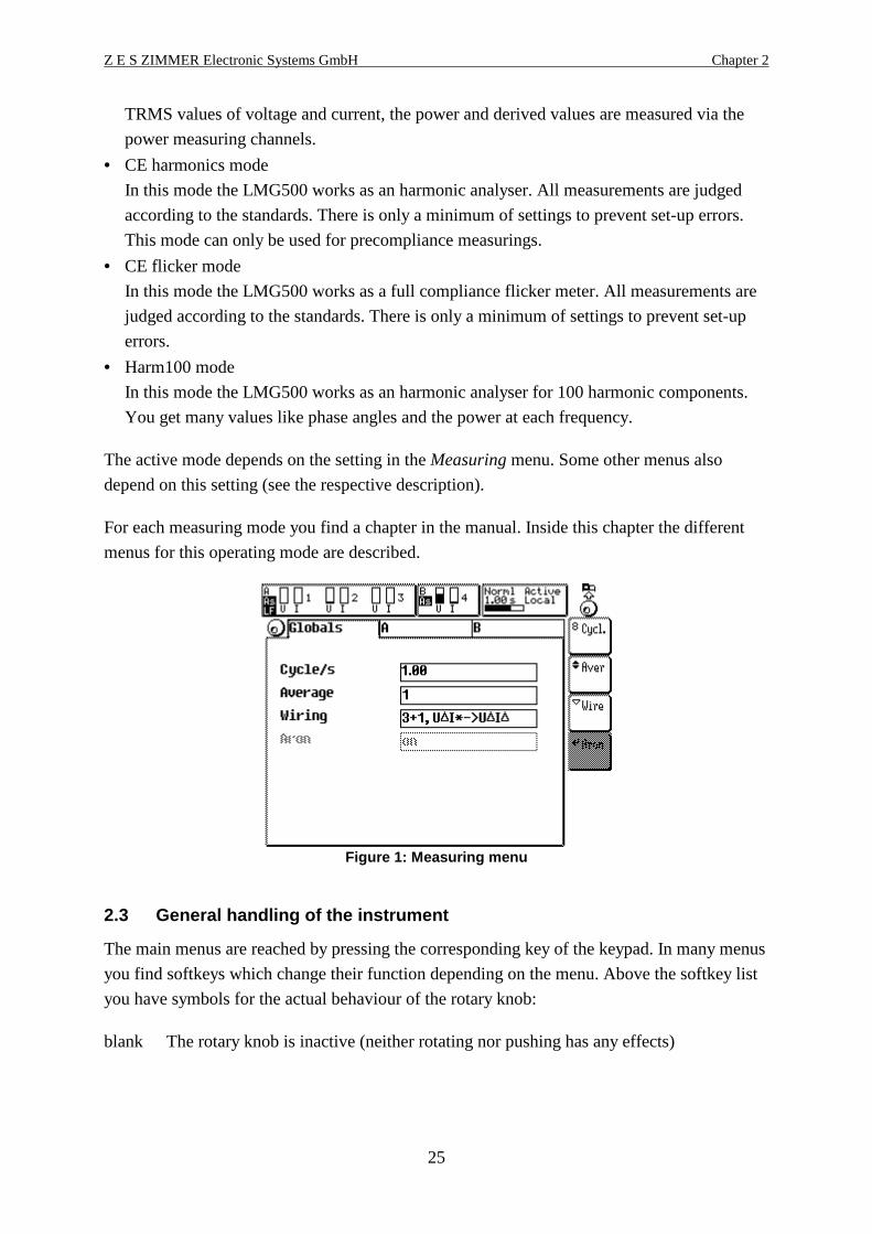
The active mode depends on the setting in the Measuring menu. Some other menus also
depend on this setting (see the respective description).
For each measuring mode you find a chapter in the manual. Inside this chapter the different
menus for this operating mode are described.
Figure 1: Measuring menu
2.3 General handling of the instrument
The main menus are reached by pressing the corresponding key of the keypad. In many menus
you find softkeys which change their function depending on the menu. Above the softkey list
you have symbols for the actual behaviour of the rotary knob:
blank The rotary knob is inactive (neither rotating nor pushing has any effects)

General LMG500
26
By rotating the knob, you can select different tabs. By pushing the knob, you get a
new selection of softkeys in a lower menu layer.
By rotating the knob, you can select different actions (depends on the context of the
menu). By pushing the knob, you go back one menu to the upper menu layer.
You are entering a text. The effect of the rotating depends on the softkey settings. By
pushing the knob, the character at the cursor position of the selection list is copied to
the input field. See also ‘4.5, Entering identifiers, characters and text’
All softkeys are of following types. They are identified by the small symbol in the
upper left corner. The text in the softkeys depends on the context of the menu.
Execution softkey. The action described by the text is executed immediately without
the possibility to cancel it.
Branch softkey. After pressing this softkey a new list of softkeys will appear. Now
you can select one of this new softkeys or you can cancel the action be pressing ESC.
List softkey. After pressing this softkey you get a selection list. You can choose one
element of the list (with the rotary knob) and then you can confirm your choice by
pressing the rotary knob or ENTER or you can cancel the selection by pressing ESC.
Text edit softkey. After pressing this softkey you can enter identifiers (for example in
the script editor or to output values via the analogue outputs). This kind of text input
is described in ‘4.5, Entering identifiers, characters and text’
Rotary knob action softkey. This is a group of one or more softkeys. The softkey with
the knob symbol is the actual active (in this case the knob would move the window).
All inactive softkeys have no symbol in the upper left corner. If you in this example
press on Zoom the symbol will change to this softkey.
If you have a small box like the ‘-x-’ in the above Zoom button, the text in this box
represents the actual setting. In the above example you would zoom the signal in X
direction. If you press again this button, the content of the small box changes to ‘-y-’
and you would zoom the signal in Y direction.
Z E S ZIMMER Electronic Systems GmbH Chapter 2
27
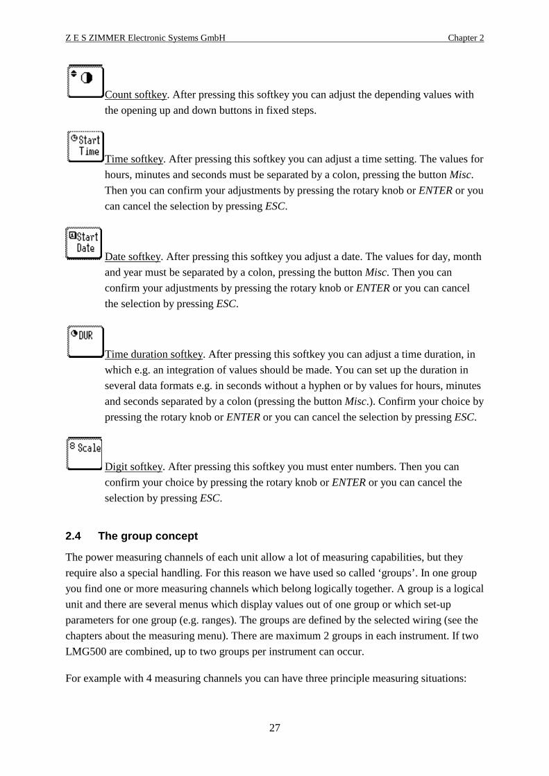
Count softkey. After pressing this softkey you can adjust the depending values with
the opening up and down buttons in fixed steps.
Time softkey. After pressing this softkey you can adjust a time setting. The values for
hours, minutes and seconds must be separated by a colon, pressing the button Misc.
Then you can confirm your adjustments by pressing the rotary knob or ENTER or you
can cancel the selection by pressing ESC.
Date softkey. After pressing this softkey you adjust a date. The values for day, month
and year must be separated by a colon, pressing the button Misc. Then you can
confirm your adjustments by pressing the rotary knob or ENTER or you can cancel
the selection by pressing ESC.
Time duration softkey. After pressing this softkey you can adjust a time duration, in
which e.g. an integration of values should be made. You can set up the duration in
several data formats e.g. in seconds without a hyphen or by values for hours, minutes
and seconds separated by a colon (pressing the button Misc.). Confirm your choice by
pressing the rotary knob or ENTER or you can cancel the selection by pressing ESC.
Digit softkey. After pressing this softkey you must enter numbers. Then you can
confirm your choice by pressing the rotary knob or ENTER or you can cancel the
selection by pressing ESC.
2.4 The group concept
The power measuring channels of each unit allow a lot of measuring capabilities, but they
require also a special handling. For this reason we have used so called ‘groups’. In one group
you find one or more measuring channels which belong logically together. A group is a logical
unit and there are several menus which display values out of one group or which set-up
parameters for one group (e.g. ranges). The groups are defined by the selected wiring (see the
chapters about the measuring menu). There are maximum 2 groups in each instrument. If two
LMG500 are combined, up to two groups per instrument can occur.
For example with 4 measuring channels you can have three principle measuring situations:
General LMG500
28
• You measure with all channels (group A) at the same system (which means you have the
same frequency at each input). Examples for such systems are 4 phase motors driven by
frequency converters or standard main supply with L1, L2, L3, N and PE (in this case you
could for example measure IN and UNPE!)
In this situation there is no group B!
The standard wiring for this is ‘4+0 channels’.
• You measure with the first channels (group A) at one system and with the last channel
(group B) at another system. Examples for such systems are standard 3 phase systems with
one phase output, motor applications at frequency converters where the torque is measured
with the 4th channel or car applications, where the 4th channel measures the DC power of
the battery.
The standard wiring for this is ‘3+1 channels’.
If you have installed the option star to delta conversion, (L50-O6) you have three further
possible wirings:
‘3+1, U*I*->U ∆I∆’
‘3+1, U∆I*->U ∆I∆’
‘3+1, U∆I*->U*I*’
• You measure with 2 channels (group A) at one system and with the other two channels
(group B) at the second system. Examples for this could be three phase converter from
50Hz to 60Hz.
Both groups are measured in 2 wattmeter method. There are two possible applications:
You measure a 3phase, 3wire system (aron circuit, Aron set to on)
You measure a 2phase, 3wire system.(Aron set to off).
The standard wiring for this is ‘2+2 channels’.
If a group has more than one measuring channel, you can get additional information about the
group:
• In many cases the instantaneous values of all used measuring channels are calculated
together. By this you can see for example the not measured voltages and currents in wiring
‘A:1+2 B:3+4’ (aron circuit).
This virtual channel can be used like a standard channel (you get all values, scope,
harmonics, flicker, ...)
This kind of channels we call ‘linked channels’
• The total values of a group are calculated (total active power, total power factor, total
energy, ...).
This kind of channels we call ‘sum channels’.

Z E S ZIMMER Electronic Systems GmbH Chapter 2
29
Following you find an overview over the different wirings, the groups, the measured values
and where you can find the values in the display. The definition of the header can be found in
chapter 5.4, ‘Display of values’.
Wiring ‘1+0 Channels’ (1 channel instruments only)
Display
channel
Group Meaning Header
1 A The values measured with the first measuring channel Chn1 A:1
Wiring ‘2+0 Channels’ (2 channel instruments only)
Display
channel
Group Meaning Header with Aron set
to off
1 A The values measured with the first measuring
channel
Chn1 (U12, I1) A:1
2 A The values measured with the second measuring
channel
Chn2 (32, I3) A:2
9 A The calculated (not measured) current I3 and
voltage U12 of group A (linked channel)
Link12 (U31, I2) A:9
15 A The total values (sum channel) of group A (display
channel 1 to 2)
Sum(1-2) A:15
Wiring ‘2+0 Channels’ (2 channel instruments only)
Display
channel
Group Meaning Header with Aron
set to on
1 A The values measured with the first measuring
channel
Chn1 A:1
2 A The values measured with the second measuring
channel
Chn2 A:2
9 A The calculated (not measured) current I3 and voltage
U12 of group A (linked channel)
Link12 (U3,I3) A:9
15 A The total values (sum channel) of group A (display
channel 1 to 2)
Sum(1-2) A:15
Wiring ‘1+1 Channels’ (2 channel instruments only)
Display
channel
Group Meaning Header
1 A The values measured with the first measuring channel Chn1 A:1
2 B The values measured with the second measuring
channel
Chn2 B:2
General LMG500
30
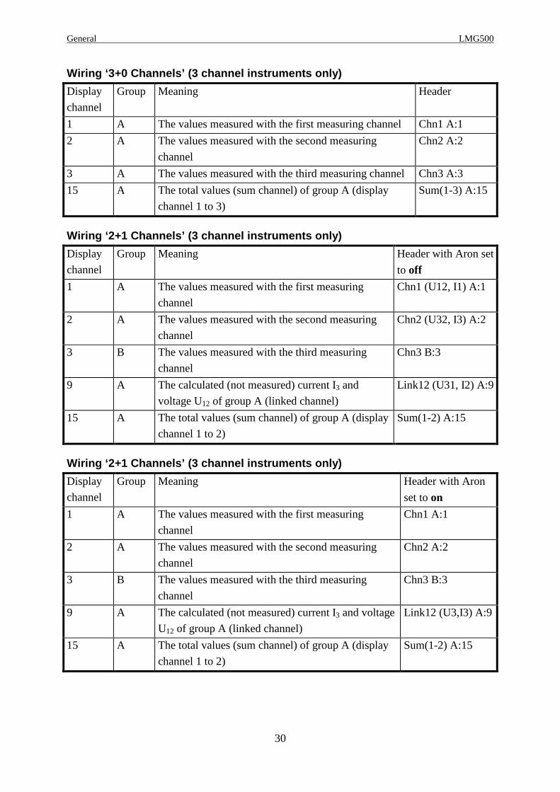
Wiring ‘3+0 Channels’ (3 channel instruments only)
Display
channel
Group Meaning Header
1 A The values measured with the first measuring channel Chn1 A:1
2 A The values measured with the second measuring
channel
Chn2 A:2
3 A The values measured with the third measuring channel Chn3 A:3
15 A The total values (sum channel) of group A (display
channel 1 to 3)
Sum(1-3) A:15
Wiring ‘2+1 Channels’ (3 channel instruments only)
Display
channel
Group Meaning Header with Aron set
to off
1 A The values measured with the first measuring
channel
Chn1 (U12, I1) A:1
2 A The values measured with the second measuring
channel
Chn2 (U32, I3) A:2
3 B The values measured with the third measuring
channel
Chn3 B:3
9 A The calculated (not measured) current I3 and
voltage U12 of group A (linked channel)
Link12 (U31, I2) A:9
15 A The total values (sum channel) of group A (display
channel 1 to 2)
Sum(1-2) A:15
Wiring ‘2+1 Channels’ (3 channel instruments only)
Display
channel
Group Meaning Header with Aron
set to on
1 A The values measured with the first measuring
channel
Chn1 A:1
2 A The values measured with the second measuring
channel
Chn2 A:2
3 B The values measured with the third measuring
channel
Chn3 B:3
9 A The calculated (not measured) current I3 and voltage
U12 of group A (linked channel)
Link12 (U3,I3) A:9
15 A The total values (sum channel) of group A (display
channel 1 to 2)
Sum(1-2) A:15

Z E S ZIMMER Electronic Systems GmbH Chapter 2
31
Wiring ‘4+0 Channels’ (4 channel instruments only)
Display
channel
Group Meaning Header
1 A The values measured with the first measuring channel Chn1 A:1
2 A The values measured with the second measuring
channel
Chn2 A:2
3 A The values measured with the third measuring channel Chn3 A:3
4 A The values measured with the fourth measuring channel Chn4 A:4
15 A The total values (sum channel) of group A (display
channel 1 to 4)
Sum(1-4) A:15
For typical measuring circuit see 3.3.1, ‘Measuring circuit for typical line applications using
the internal current path’.
Wiring ‘3+1 Channels’ (4 channel instruments only)
Display
channel
Group Meaning Header
1 A The values measured with the first measuring channel Chn1 A:1
2 A The values measured with the second measuring channel Chn2 A:2
3 A The values measured with the third measuring channel Chn3 A:3
4 B The values measured with the fourth measuring channel Chn4 B:4
15 A The total values (sum channel) of group A (display
channel 1 to 3)
Sum(1-3) A:15
For typical measuring circuit see 3.3.2, ‘Measuring circuit for measuring efficiency of
3/1phase systems’.
Wiring ‘2+2 Channels’ (4 channel instruments only)
Display
channel
Group Meaning Header with Aron
set to off
1 A The values measured with the first measuring
channel
Chn1 A:1
2 A The values measured with the second measuring
channel
Chn2 A:2
3 B The values measured with the third measuring
channel
Chn3 B:3
4 B The values measured with the fourth measuring
channel
Chn4 B:4

General LMG500
32
Display
channel
Group Meaning Header with Aron
set to off
9 A The calculated (not measured) current I3 and voltage
U12 of group A (linked channel)
Link12 (U3,I3) A:9
10 B The calculated (not measured) current I3 and voltage
U12 of group B (linked channel)
Link34 (U3,I3) B:10
15 A The total values (sum channel) of group A (display
channel 1 to 2)
Sum(1-2) A:15
16 B The total values (sum channel) of group B (display
channel 3 to 4)
Sum(3-4) B:16
For typical measuring circuit see 3.3.5, ‘Measuring circuit for measuring efficiency of
3/3phase systems’ if you replace ‘L2’ by ‘N’.
Wiring ‘2+2 Channels’ (4 channel instruments only)
Display
channel
Group Meaning Header with Aron set
to on
1 A The values measured with the first measuring
channel
Chn1 (U12,I1) A:1
2 A The values measured with the second measuring
channel
Chn2 (U32,I3) A:2
3 B The values measured with the third measuring
channel
Chn3 (U12,I1) B:3
4 B The values measured with the fourth measuring
channel
Chn4 (U32,I3) B:4
9 A The calculated (not measured) current I2 and
voltage U31 of group A (linked channel)
Link12 (U31,I2) A:9
10 B The calculated (not measured) current I2 and
voltage U31 of group B (linked channel)
Link34 (U31,I2) B:10
15 A The total values (sum channel) of group A (display
channel 1 to 2)
Sum(1-2) A:15
16 B The total values (sum channel) of group B (display
channel 3 to 4)
Sum(3-4) B:16
For typical measuring circuit see 3.3.5, ‘Measuring circuit for measuring efficiency of
3/3phase systems’.
For further information about this tables see also chapter 5.3, ‘Definition of measuring
values’.
So a general rule what you see is:
All measuring channels
Z E S ZIMMER Electronic Systems GmbH Chapter 2
33
All channels calculated from sample values (linked channels)
All channels calculating the total values of a group (sum channels)
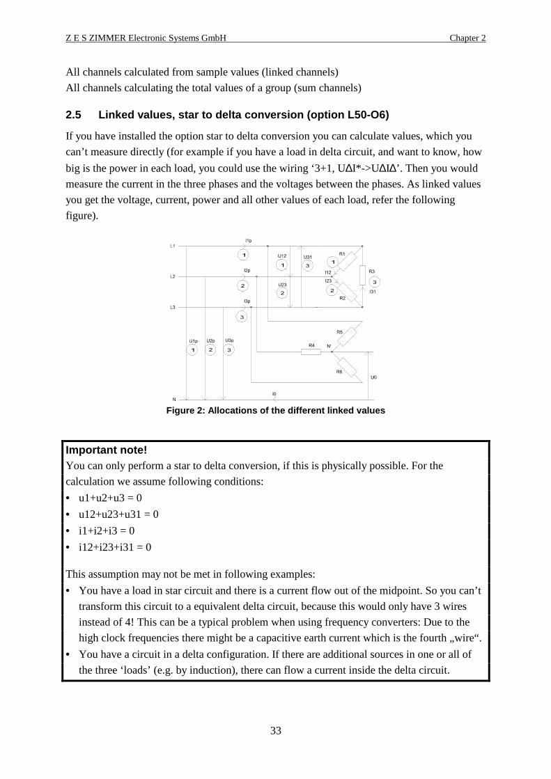
2.5 Linked values, star to delta conversion (option L50-O6)
If you have installed the option star to delta conversion you can calculate values, which you
can’t measure directly (for example if you have a load in delta circuit, and want to know, how
big is the power in each load, you could use the wiring ‘3+1, U∆I*->U ∆I∆’. Then you would
measure the current in the three phases and the voltages between the phases. As linked values
you get the voltage, current, power and all other values of each load, refer the following
figure).
Figure 2: Allocations of the different linked value s
Important note!You can only perform a star to delta conversion, if this is physically possible. For the
calculation we assume following conditions:
• u1+u2+u3 = 0
• u12+u23+u31 = 0
• i1+i2+i3 = 0
• i12+i23+i31 = 0
This assumption may not be met in following examples:
• You have a load in star circuit and there is a current flow out of the midpoint. So you can’t
transform this circuit to a equivalent delta circuit, because this would only have 3 wires
instead of 4! This can be a typical problem when using frequency converters: Due to the
high clock frequencies there might be a capacitive earth current which is the fourth „wire“.
• You have a circuit in a delta configuration. If there are additional sources in one or all of
the three ‘loads’ (e.g. by induction), there can flow a current inside the delta circuit.
General LMG500
34
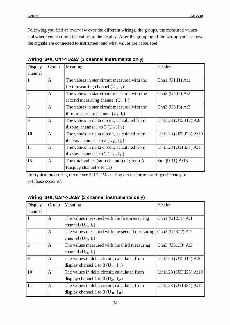
Following you find an overview over the different wirings, the groups, the measured values
and where you can find the values in the display. After the grouping of the wiring you see how
the signals are connected to instrument and what values are calculated.
Wiring ‘3+0, U*I*->U ∆∆∆∆I∆∆∆∆’ (3 channel instruments only)
Display
channel
Group Meaning Header
1 A The values in star circuit measured with the
first measuring channel (U1, I1)
Chn1 (U1,I1) A:1
2 A The values in star circuit measured with the
second measuring channel (U2, I2)
Chn2 (U2,I2) A:2
3 A The values in star circuit measured with the
third measuring channel (U3, I3)
Chn3 (U3,I3) A:3
9 A The values in delta circuit, calculated from
display channel 1 to 3 (U12, I12)
Link123 (U12,I12) A:9
10 A The values in delta circuit, calculated from
display channel 1 to 3 (U23, I23)
Link123 (U23,I23) A:10
11 A The values in delta circuit, calculated from
display channel 1 to 3 (U31, I31)
Link123 (U31,I31) A:11
15 A The total values (sum channel) of group A
(display channel 9 to 11)
Sum(9-11) A:15
For typical measuring circuit see 3.3.2, ‘Measuring circuit for measuring efficiency of
3/1phase systems’.
Wiring ‘3+0, U ∆∆∆∆I*->U∆∆∆∆I∆∆∆∆’ (3 channel instruments only)
Display
channel
Group Meaning Header
1 A The values measured with the first measuring
channel (U12, I1)
Chn1 (U12,I1) A:1
2 A The values measured with the second measuring
channel (U23, I2)
Chn2 (U23,I2) A:2
3 A The values measured with the third measuring
channel (U31, I3)
Chn3 (U31,I3) A:3
9 A The values in delta circuit, calculated from
display channel 1 to 3 (U12, I12)
Link123 (U12,I12) A:9
10 A The values in delta circuit, calculated from
display channel 1 to 3 (U23, I23)
Link123 (U23,I23) A:10
11 A The values in delta circuit, calculated from
display channel 1 to 3 (U31, I31)
Link123 (U31,I31) A:11
Z E S ZIMMER Electronic Systems GmbH Chapter 2
35
Display
channel
Group Meaning Header
15 A The total values (sum channel) of group A
(display channel 9 to 11)
Sum(9-11) A:15
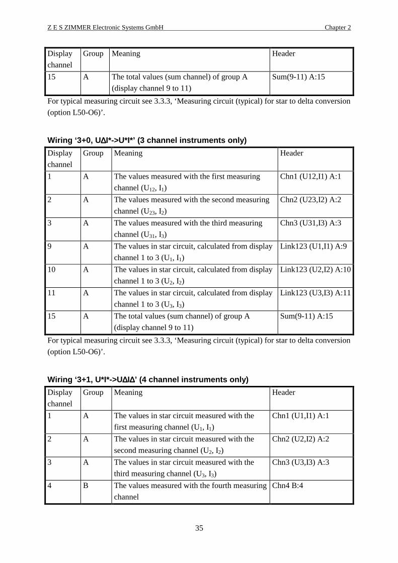
For typical measuring circuit see 3.3.3, ‘Measuring circuit (typical) for star to delta conversion
(option L50-O6)’.
Wiring ‘3+0, U ∆∆∆∆I*->U*I*’ (3 channel instruments only)
Display
channel
Group Meaning Header
1 A The values measured with the first measuring
channel (U12, I1)
Chn1 (U12,I1) A:1
2 A The values measured with the second measuring
channel (U23, I2)
Chn2 (U23,I2) A:2
3 A The values measured with the third measuring
channel (U31, I3)
Chn3 (U31,I3) A:3
9 A The values in star circuit, calculated from display
channel 1 to 3 (U1, I1)
Link123 (U1,I1) A:9
10 A The values in star circuit, calculated from display
channel 1 to 3 (U2, I2)
Link123 (U2,I2) A:10
11 A The values in star circuit, calculated from display
channel 1 to 3 (U3, I3)
Link123 (U3,I3) A:11
15 A The total values (sum channel) of group A
(display channel 9 to 11)
Sum(9-11) A:15
For typical measuring circuit see 3.3.3, ‘Measuring circuit (typical) for star to delta conversion
(option L50-O6)’.
Wiring ‘3+1, U*I*->U ∆∆∆∆I∆∆∆∆’ (4 channel instruments only)
Display
channel
Group Meaning Header
1 A The values in star circuit measured with the
first measuring channel (U1, I1)
Chn1 (U1,I1) A:1
2 A The values in star circuit measured with the
second measuring channel (U2, I2)
Chn2 (U2,I2) A:2
3 A The values in star circuit measured with the
third measuring channel (U3, I3)
Chn3 (U3,I3) A:3
4 B The values measured with the fourth measuring
channel
Chn4 B:4

General LMG500
36
Display
channel
Group Meaning Header
9 A The values in delta circuit, calculated from
display channel 1 to 3 (U12, I12)
Link123 (U12,I12) A:9
10 A The values in delta circuit, calculated from
display channel 1 to 3 (U23, I23)
Link123 (U23,I23) A:10
11 A The values in delta circuit, calculated from
display channel 1 to 3 (U31, I31)
Link123 (U31,I31) A:11
15 A The total values (sum channel) of group A
(display channel 9 to 11)
Sum(9-11) A:15
For typical measuring circuit see 3.3.2, ‘Measuring circuit for measuring efficiency of
3/1phase systems’.
Wiring ‘3+1, U ∆∆∆∆I*->U∆∆∆∆I∆∆∆∆’ (4 channel instruments only)
Display
channel
Group Meaning Header
1 A The values measured with the first measuring
channel (U12, I1)
Chn1 (U12,I1) A:1
2 A The values measured with the second measuring
channel (U23, I2)
Chn2 (U23,I2) A:2
3 A The values measured with the third measuring
channel (U31, I3)
Chn3 (U31,I3) A:3
4 B The values measured with the fourth measuring
channel
Chn4 B:4
9 A The values in delta circuit, calculated from
display channel 1 to 3 (U12, I12)
Link123 (U12,I12) A:9
10 A The values in delta circuit, calculated from
display channel 1 to 3 (U23, I23)
Link123 (U23,I23) A:10
11 A The values in delta circuit, calculated from
display channel 1 to 3 (U31, I31)
Link123 (U31,I31) A:11
15 A The total values (sum channel) of group A
(display channel 9 to 11)
Sum(9-11) A:15
For typical measuring circuit see 3.3.3, ‘Measuring circuit (typical) for star to delta conversion
(option L50-O6)’.
Wiring ‘3+1, U ∆∆∆∆I*->U*I*’ (4 channel instruments only)
Display
channel
Group Meaning Header

Z E S ZIMMER Electronic Systems GmbH Chapter 2
37
Display
channel
Group Meaning Header
1 A The values measured with the first measuring
channel (U12, I1)
Chn1 (U12,I1) A:1
2 A The values measured with the second measuring
channel (U23, I2)
Chn2 (U23,I2) A:2
3 A The values measured with the third measuring
channel (U31, I3)
Chn3 (U31,I3) A:3
4 B The values measured with the fourth measuring
channel
Chn4 B:4
9 A The values in star circuit, calculated from display
channel 1 to 3 (U1, I1)
Link123 (U1,I1) A:9
10 A The values in star circuit, calculated from display
channel 1 to 3 (U2, I2)
Link123 (U2,I2) A:10
11 A The values in star circuit, calculated from display
channel 1 to 3 (U3, I3)
Link123 (U3,I3) A:11
15 A The total values (sum channel) of group A
(display channel 9 to 11)
Sum(9-11) A:15
For typical measuring circuit see 3.3.3, ‘Measuring circuit (typical) for star to delta conversion
(option L50-O6)’.
For further information about this tables see also chapter 5.3, ‘Definition of measuring
values’.
2.6 More than 4 power measuring channels
If you connect a 2nd LMG500 or an extension box to the basic instrument, you can use up to 4
additional power measuring channels. If you have an instrument with up to 8 channels, it is
internally the same like a 4 channel instrument and a second one. This additional channels are
placed in the groups ‘C’ and ‘D’. In principle for the second unit you have the same wiring
selections:
Wiring ‘1+0 Channels’ (1 extention channel instrume nts only)
Display
channel
Group Meaning Header
5 C The values measured with the first extension/fifth
measuring channel
Chn5 C:5
Wiring ‘2+0 Channels’(2 extention channel instrumen ts only)
Display
channel
Group Meaning Header

General LMG500
38
Display
channel
Group Meaning Header
5 C The values measured with the first extension/fifth
measuring channel
Chn5 C:5
6 C The values measured with the second
extension/sixth measuring channel
Chn6 C:6
12 C The calculated (not measured) current I3 and
voltage U12 of group C (linked channel)
Link56 (U3,I3) C:12
17 C The total values (sum channel) of group C (display
channel 5 to 6)
Sum(5-6) C:17
Wiring ‘1+1 Channels’(2 extention channel instrumen ts only)
Display
channel
Group Meaning Header
5 C The values measured with the first extension/fifth
measuring channel
Chn5 C:5
6 D The values measured with the second extension/sixth
measuring channel
Chn6 D:6
Wiring ‘3+0 Channels’(3 extention channel instrumen ts only)
Display
channel
Group Meaning Header
5 C The values measured with the first extension/fifth
measuring channel
Chn5 C:5
6 C The values measured with the second extension/sixth
measuring channel
Chn6 C:6
7 C The values measured with the third extension/seventh
measuring channel
Chn7 C:7
17 C The total values (sum channel) of group C (display
channel 5 to 7)
Sum(5-7) C:17
Wiring ‘2+1 Channels’(3 extention channel instrumen ts only)
Display
channel
Group Meaning Header
5 C The values measured with the first extension/fifth
measuring channel
Chn5 C:5
6 C The values measured with the second
extension/sixth measuring channel
Chn6 C:6
7 D The values measured with the third
extension/seventh measuring channel
Chn7 D:7

Z E S ZIMMER Electronic Systems GmbH Chapter 2
39
Display
channel
Group Meaning Header
12 C The calculated (not measured) current I3 and
voltage U12 of group C (linked channel)
Link56 (U3,I3) C:12
17 C The total values (sum channel) of group C (display
channel 5 to 6)
Sum(5-6) C:17
Wiring ‘4+0 Channels’(4 extention channel instrumen ts only)
Display
channel
Group Meaning Header
5 C The values measured with the first extension/fifth
measuring channel
Chn5 C:5
6 C The values measured with the second extension/sixth
measuring channel
Chn6 C:6
7 C The values measured with the third extension/seventh
measuring channel
Chn7 C:7
8 C The values measured with the fourth extension/eighth
measuring channel
Chn8 C:8
17 C The total values (sum channel) of group C (display
channel 1 to 4)
Sum(5-8) C:17
Wiring ‘3+1 Channels’(4 extention channel instrumen ts only)
Display
channel
Group Meaning Header
5 C The values measured with the first extension/fifth
measuring channel
Chn5 C:5
6 C The values measured with the second extension/sixth
measuring channel
Chn6 C:6
7 C The values measured with the third extension/seventh
measuring channel
Chn7 C:7
8 D The values measured with the fourth extension/eighth
measuring channel
Chn8 D:8
17 C The total values (sum channel) of group C (display
channel 5 to 7)
Sum(5-7) C:17
Wiring ‘2+2 Channels’(4 extention channel instrumen ts only)
Display
channel
Group Meaning Header with Aron
set to off

General LMG500
40
Display
channel
Group Meaning Header with Aron
set to off
5 C The values measured with the first extension/fifth
measuring channel
Chn5 C:5
6 C The values measured with the second
extension/sixth measuring channel
Chn6 C:6
7 D The values measured with the third
extension/seventh measuring channel
Chn7 D:7
8 D The values measured with the fourth
extension/eighth measuring channel
Chn8 D:8
12 C The calculated (not measured) current I3 and voltage
U12 of group C (linked channel)
Link56 (U3,I3) C:12
13 D The calculated (not measured) current I3 and voltage
U12 of group D (linked channel)
Link78 (U3,I3) D:13
17 C The total values (sum channel) of group C (display
channel 5 to 6)
Sum(5-6) C:17
18 D The total values (sum channel) of group D (display
channel 7 to 8)
Sum(7-8) D:18
Wiring ‘2+2 Channels’(4 extention channel instrumen ts only)
Display
channel
Group Meaning Header with Aron set
to on
5 C The values measured with the first extension/fifth
measuring channel
Chn1 (U12,I1) A:1
6 C The values measured with the second
extension/sixth measuring channel
Chn2 (U32,I3) A:2
7 D The values measured with the third
extension/seventh measuring channel
Chn3 (U12,I1) B:3
8 D The values measured with the fourth
extension/eighth measuring channel
Chn4 (U32,I3) B:4
12 C The calculated (not measured) current I2 and
voltage U31 of group C (linked channel)
Link56 (U31,I2) C:12
13 D The calculated (not measured) current I2 and
voltage U31 of group D (linked channel)
Link78 (U31,I2) D:13
17 C The total values (sum channel) of group C (display
channel 5 to 6)
Sum(5-6) C:17
18 D The total values (sum channel) of group D (display
channel 7 to 8)
Sum(7-8) D:18

Z E S ZIMMER Electronic Systems GmbH Chapter 2
41
Wiring ‘3+0, U*I*->U ∆∆∆∆I∆∆∆∆’ (3 extention channel instruments only)
Display
channel
Group Meaning Header
5 C The values in star circuit measured with the
first extension/fifth measuring channel (U1, I1)
Chn5 (U1,I1) C:5
6 C The values in star circuit measured with the
second extension/sixth measuring channel (U2,
I2)
Chn6 (U2,I2) C:6
7 C The values in star circuit measured with the
third extension/seventh measuring channel (U3,
I3)
Chn7 (U3,I3) C:7
12 C The values in delta circuit, calculated from
display channel 5 to 7 (U12, I12)
Link567 (U12,I12) C:12
13 C The values in delta circuit, calculated from
display channel 5 to 7 (U23, I23)
Link567 (U23,I23) C:13
14 C The values in delta circuit, calculated from
display channel 5 to 7 (U31, I31)
Link567 (U31,I31) C:14
17 C The total values (sum channel) of group C
(display channel 12 to 14)
Sum(12-14) C:17
Wiring ‘3+0, U ∆∆∆∆I*->U∆∆∆∆I∆∆∆∆’ (3 extention channel instruments only)
Display
channel
Group Meaning Header
5 C The values measured with the first
extension/fifth measuring channel (U12, I1)
Chn5 (U12,I1) C:5
6 C The values measured with the second
extension/sixth measuring channel (U23, I2)
Chn6 (U23,I2) C:6
7 C The values measured with the third
extension/seventh measuring channel (U31, I3)
Chn7 (U31,I3) C:7
12 C The values in delta circuit, calculated from
display channel 5 to 7 (U12, I12)
Link567 (U12,I12) C:12
13 C The values in delta circuit, calculated from
display channel 5 to 7 (U23, I23)
Link567 (U23,I23) C:13
14 C The values in delta circuit, calculated from
display channel 5 to 7 (U31, I31)
Link567 (U31,I31) C:14
17 C The total values (sum channel) of group C
(display channel 12 to 14)
Sum(12-14) C:17
General LMG500
42
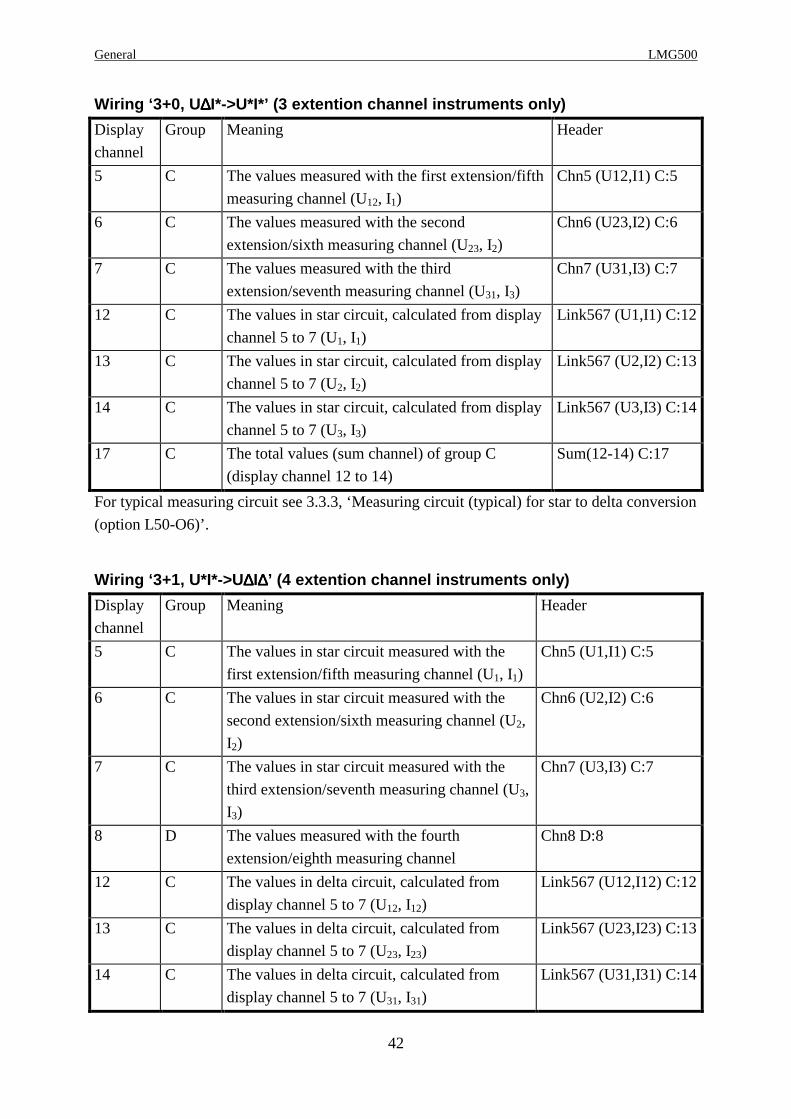
Wiring ‘3+0, U ∆∆∆∆I*->U*I*’ (3 extention channel instruments only)
Display
channel
Group Meaning Header
5 C The values measured with the first extension/fifth
measuring channel (U12, I1)
Chn5 (U12,I1) C:5
6 C The values measured with the second
extension/sixth measuring channel (U23, I2)
Chn6 (U23,I2) C:6
7 C The values measured with the third
extension/seventh measuring channel (U31, I3)
Chn7 (U31,I3) C:7
12 C The values in star circuit, calculated from display
channel 5 to 7 (U1, I1)
Link567 (U1,I1) C:12
13 C The values in star circuit, calculated from display
channel 5 to 7 (U2, I2)
Link567 (U2,I2) C:13
14 C The values in star circuit, calculated from display
channel 5 to 7 (U3, I3)
Link567 (U3,I3) C:14
17 C The total values (sum channel) of group C
(display channel 12 to 14)
Sum(12-14) C:17
For typical measuring circuit see 3.3.3, ‘Measuring circuit (typical) for star to delta conversion
(option L50-O6)’.
Wiring ‘3+1, U*I*->U ∆∆∆∆I∆∆∆∆’ (4 extention channel instruments only)
Display
channel
Group Meaning Header
5 C The values in star circuit measured with the
first extension/fifth measuring channel (U1, I1)
Chn5 (U1,I1) C:5
6 C The values in star circuit measured with the
second extension/sixth measuring channel (U2,
I2)
Chn6 (U2,I2) C:6
7 C The values in star circuit measured with the
third extension/seventh measuring channel (U3,
I3)
Chn7 (U3,I3) C:7
8 D The values measured with the fourth
extension/eighth measuring channel
Chn8 D:8
12 C The values in delta circuit, calculated from
display channel 5 to 7 (U12, I12)
Link567 (U12,I12) C:12
13 C The values in delta circuit, calculated from
display channel 5 to 7 (U23, I23)
Link567 (U23,I23) C:13
14 C The values in delta circuit, calculated from
display channel 5 to 7 (U31, I31)
Link567 (U31,I31) C:14

Z E S ZIMMER Electronic Systems GmbH Chapter 2
43
Display
channel
Group Meaning Header
17 C The total values (sum channel) of group A
(display channel 12 to 14)
Sum(12-14) C:17
Wiring ‘3+1, U ∆∆∆∆I*->U∆∆∆∆I∆∆∆∆’ (4 extention channel instruments only)
Display
channel
Group Meaning Header
5 C The values measured with the first
extension/fifth measuring channel (U12, I1)
Chn5 (U12,I1) C:5
6 C The values measured with the second
extension/sixth measuring channel (U23, I2)
Chn6 (U23,I2) C:6
7 C The values measured with the third
extension/seventh measuring channel (U31, I3)
Chn7 (U31,I3) C:7
8 D The values measured with the fourth
extension/eighth measuring channel
Chn8 D:8
12 C The values in delta circuit, calculated from
display channel 5 to 7 (U12, I12)
Link567 (U12,I12) C:12
13 C The values in delta circuit, calculated from
display channel 5 to 7 (U23, I23)
Link567 (U23,I23) C:13
14 C The values in delta circuit, calculated from
display channel 5 to 7 (U31, I31)
Link567 (U31,I31) C:14
17 C The total values (sum channel) of group C
(display channel 12 to 14)
Sum(12-14) C:17
Wiring ‘3+1, U ∆∆∆∆I*->U*I*’ (4 extention channel instruments only)
Display
channel
Group Meaning Header
5 C The values measured with the first extension/fifth
measuring channel (U12, I1)
Chn5 (U12,I1) C:5
6 C The values measured with the second
extension/sixth measuring channel (U23, I2)
Chn6 (U23,I2) C:6
7 C The values measured with the third
extension/seventh measuring channel (U31, I3)
Chn7 (U31,I3) C:7
8 D The values measured with the fourth
extension/eighth measuring channel
Chn8 D:8
12 C The values in star circuit, calculated from display
channel 5 to 7 (U1, I1)
Link567 (U1,I1) C:12
13 C The values in star circuit, calculated from display
channel 5 to 7 (U2, I2)
Link567 (U2,I2) C:13

General LMG500
44
Display
channel
Group Meaning Header
14 C The values in star circuit, calculated from display
channel 5 to 7 (U3, I3)
Link567 (U3,I3) C:14
17 C The total values (sum channel) of group C
(display channel 12 to 14)
Sum(12-14) C:17
Z E S ZIMMER Electronic Systems GmbH Chapter 3
45
3 Installation
3.1 Unpacking and putting into operation
Having unpacked the equipment, it should be checked for signs of damage. Damage due to
transportation should be reported to the equipment supplier at the earliest opportunity. If it is
uncertain to use the damaged equipment safely, then the equipment should not be used.
The package should be stored for further transports (e.g. for the annual calibration according
to ISO9000).
After delivery the following items should be present:
• 1 LMG500 with the ordered number ‘n’ of measuring channels
• 1 User manual
• n*4 Safety laboratory leads, 2.5mm², 1m, 1/2 in violet, 1/2 in grey
• 1 Mains supply cable
Further accessories as listed in the delivery note.
The instrument should only be used in a clean and dry environment and must never be
operated in excessively dusty or moist spaces. To ascertain sufficient air circulation the
instrument should be operated in a horizontal position or tilted only to the degree possible by
of the adjustable handle. The instrument should not operate in direct sunlight.
3.2 General set-up
In general the instrument stores the actual settings as well as the last used menu. Pressing the
both lower softkeys when switching on the instrument will reset all settings to the default
parameters.
By this you can delete faulty scripts, which could block the instrument.
3.3 Connections of the LMG500
First of all please refer to chapter 1.1, ‘Safety Instructions’.
To ensure correct power measurement polarity, connect the cabling to the test circuit so that
the grey terminals (U and I) are used as a reference. In other words, the signal source should
point towards the terminals U*, USensor, I*, IHF and ISensor.
When working with DC voltages/currents, these terminals are the positive connections.

Installation LMG500
46
The following diagrams are some examples for typical connections of the instrument. But all
other measuring circuits are also possible (e.g. circuits which measure the correct current
instead of the correct voltage).
3.3.1 Measuring circuit for typical line applicatio ns using the internal currentpath
L1
LOA
DL2L3N
PE
Usensor
Isen
sor
U*
IHF*
I*
I U
Usensor
Isen
sor
U*
IHF*
I*
I U
Usensor
Isen
sor
U*
IHF*
I*
I U
Usensor
Isen
sor
U*
IHF*
I*
I U
Sensor ID I1
Ch 1 Ch 2 Ch 3 Ch 4
Sensor ID I2 Sensor ID I3 Sensor ID I4Sensor ID U1 Sensor ID U2 Sensor ID U3 Sensor ID U4
Figure 3: Measuring circuit 3 phase system with neu tral
In this circuit we measure with the first three channels the voltage, current and power of the
three phase system. With the fourth channel we measure additionally the current in the neutral
wire and the voltage between neutral and earth. Of course you can use the same circuit
without the fourth channel, if you are not interested in this values.
This circuit should be measured with wiring ‘3+1 Channels’.
Wiring ‘4+0 Channels’ is also possible, but then the measured power of channel 4 would be
added to the total power of the system (this could be correct, but depends very much on what
you want to measure!).
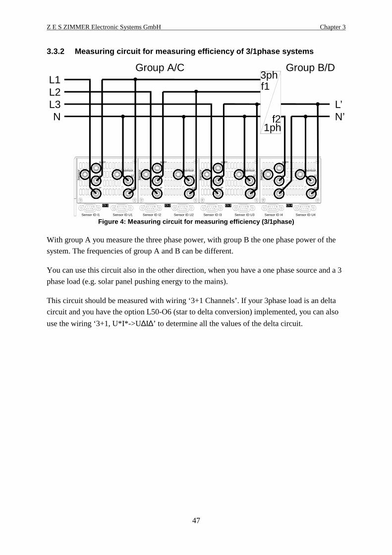
Z E S ZIMMER Electronic Systems GmbH Chapter 3
47
3.3.2 Measuring circuit for measuring efficiency of 3/1phase systems
L1Group A/C Group B/D
L2L3 L’N
3ph
1ph
f1
f2 N’
Usensor
Isen
sor
U*
IHF*
I*
I U
Usensor
Isen
sor
U*
IHF*
I*
I U
Usensor
Isen
sor
U*
IHF*
I*
I U
Usensor
Isen
sor
U*
IHF*
I*
I U
Sensor ID I1
Ch 1 Ch 2 Ch 3 Ch 4
Sensor ID I2 Sensor ID I3 Sensor ID I4Sensor ID U1 Sensor ID U2 Sensor ID U3 Sensor ID U4
Figure 4: Measuring circuit for measuring efficienc y (3/1phase)
With group A you measure the three phase power, with group B the one phase power of the
system. The frequencies of group A and B can be different.
You can use this circuit also in the other direction, when you have a one phase source and a 3
phase load (e.g. solar panel pushing energy to the mains).
This circuit should be measured with wiring ‘3+1 Channels’. If your 3phase load is an delta
circuit and you have the option L50-O6 (star to delta conversion) implemented, you can also
use the wiring ‘3+1, U*I*->U∆I∆’ to determine all the values of the delta circuit.

Installation LMG500
48
3.3.3 Measuring circuit (typical) for star to delta conversion (option L50-O6)
L1L2L3
Motor
Usensor
Isen
sor
U*
IHF*
I*
I U
Usensor
Isen
sor
U*
IHF*
I*
I U
Usensor
Isen
sor
U*
IHF*
I*
I U
Usensor
Isen
sor
U*
IHF*
I*
I U
Sensor ID I1
Ch 1 Ch 2 Ch 3 Ch 4
Sensor ID I2 Sensor ID I3 Sensor ID I4Sensor ID U1 Sensor ID U2 Sensor ID U3 Sensor ID U4
Figure 5: Star to delta conversion
With group A you measure the linked voltages and the currents in the phases. The LMG500
calculates with this both values a power for each channel, but this power will not be the power
of the system, because the measured voltages (U12, U23 and U31) belong not to the currents (I1,
I2 and I3). The power values are a mix from star and delta values.
But with the star to delta conversion, you can either transform the voltages to star voltages or
you can transform the currents to delta currents. This will depend on your load. Now you have
voltage and current in the same circuit and now you have also power values which exist in
your circuit.
However the group B can be used independently like in the above examples.
This circuit should be measured with wiring ‘3+1, U∆I*->U ∆I∆’ or ‘3+1, U∆I*->U*I*’.
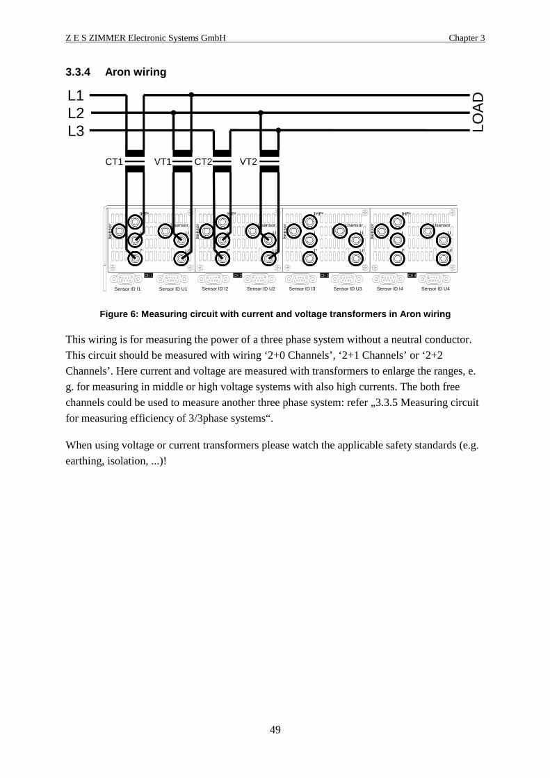
Z E S ZIMMER Electronic Systems GmbH Chapter 3
49
3.3.4 Aron wiring
L1
LOA
D
L2L3
CT1 CT2 VT2VT1
Usensor
Isen
sor
U*
IHF*
I*
I U
Usensor
Isen
sor
U*
IHF*
I*
I U
Usensor
Isen
sor
U*
IHF*
I*
I U
Usensor
Isen
sor
U*
IHF*
I*
I U
Sensor ID I1
Ch 1 Ch 2 Ch 3 Ch 4
Sensor ID I2 Sensor ID I3 Sensor ID I4Sensor ID U1 Sensor ID U2 Sensor ID U3 Sensor ID U4
Figure 6: Measuring circuit with current and voltag e transformers in Aron wiring
This wiring is for measuring the power of a three phase system without a neutral conductor.
This circuit should be measured with wiring ‘2+0 Channels’, ‘2+1 Channels’ or ‘2+2
Channels’. Here current and voltage are measured with transformers to enlarge the ranges, e.
g. for measuring in middle or high voltage systems with also high currents. The both free
channels could be used to measure another three phase system: refer „3.3.5 Measuring circuit
for measuring efficiency of 3/3phase systems“.
When using voltage or current transformers please watch the applicable safety standards (e.g.
earthing, isolation, ...)!

Installation LMG500
50
3.3.5 Measuring circuit for measuring efficiency of 3/3phase systems
L1’L1Group A/C Group B/D
3phf1
3phf2
L2’L2L3’L3
Usensor
Isen
sor
U*
IHF*
I*
I U
Usensor
Isen
sor
U*
IHF*
I*
I U
Usensor
Isen
sor
U*
IHF*
I*
I U
Usensor
Isen
sor
U*
IHF*
I*
I U
Sensor ID I1
Ch 1 Ch 2 Ch 3 Ch 4
Sensor ID I2 Sensor ID I3 Sensor ID I4Sensor ID U1 Sensor ID U2 Sensor ID U3 Sensor ID U4
Figure 7: Measuring circuit for measuring efficienc y (3/3phase)
With group A you measure the first three phase power, with group B the second one. The
frequencies of group A and B can be different. This is a double aron circuit.
This circuit should be measured with wiring ‘2+2 Channels’.
3.3.6 Measuring circuit using an external current s ensor
LOA
DL1N
Usensor
Isen
sor
U*
IHF*
I*
I U
Usensor
Isen
sor
U*
IHF*
I*
I U
Usensor
Isen
sor
U*
IHF*
I*
I U
Usensor
Isen
sor
U*
IHF*
I*
I U
Sensor ID I1
Ch 1 Ch 2 Ch 3 Ch 4
Sensor ID I2 Sensor ID I3 Sensor ID I4Sensor ID U1 Sensor ID U2 Sensor ID U3 Sensor ID U4
SensorAdaptorL50-Z14
Figure 8: Measuring circuit with external current s ensor
Here you see, how to install your current sensor.
For easy usage all ZES sensors have an EEPROM implemented in which we have stored the
name, scaling, ranges, adjustment and delay time. The LMG500 recognises automatically,
which ZES sensor is connected and sets up the range menu. Further on we correct some of the
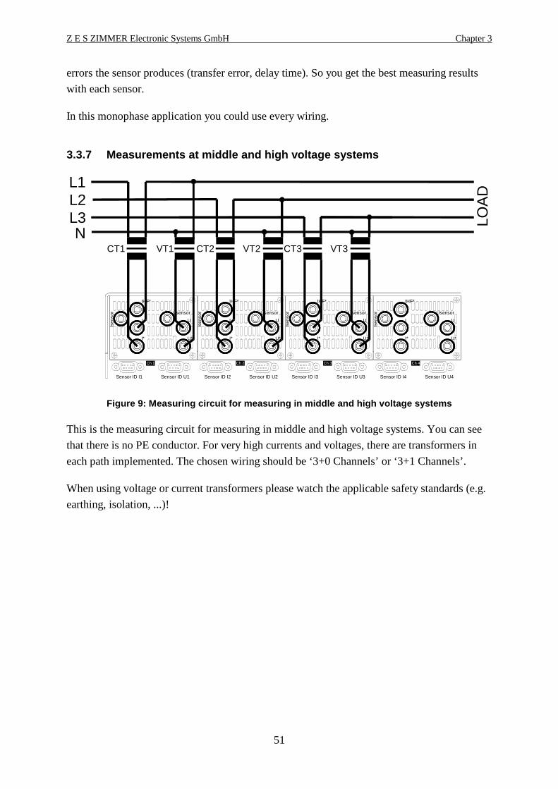
Z E S ZIMMER Electronic Systems GmbH Chapter 3
51
errors the sensor produces (transfer error, delay time). So you get the best measuring results
with each sensor.
In this monophase application you could use every wiring.
3.3.7 Measurements at middle and high voltage syste ms
L1
LOA
DL2L3N
CT1 CT3CT2 VT3VT2VT1
Usensor
Isen
sor
U*
IHF*
I*
I U
Usensor
Isen
sor
U*
IHF*
I*
I U
Usensor
Isen
sor
U*
IHF*
I*
I U
Usensor
Isen
sor
U*
IHF*
I*
I U
Sensor ID I1
Ch 1 Ch 2 Ch 3 Ch 4
Sensor ID I2 Sensor ID I3 Sensor ID I4Sensor ID U1 Sensor ID U2 Sensor ID U3 Sensor ID U4
Figure 9: Measuring circuit for measuring in middle and high voltage systems
This is the measuring circuit for measuring in middle and high voltage systems. You can see
that there is no PE conductor. For very high currents and voltages, there are transformers in
each path implemented. The chosen wiring should be ‘3+0 Channels’ or ‘3+1 Channels’.
When using voltage or current transformers please watch the applicable safety standards (e.g.
earthing, isolation, ...)!

Installation LMG500
52
3.3.8 Measurements at middle and high voltage syste ms without N
L1
LOA
D
L2L3
CT1 CT3 VT3VT1
Usensor
Isen
sor
U*
IHF*
I*
I U
Usensor
Isen
sor
U*
IHF*
I*
I U
Usensor
Isen
sor
U*
IHF*
I*
I U
Usensor
Isen
sor
U*
IHF*
I*
I U
Sensor ID I1
Ch 1 Ch 2 Ch 3 Ch 4
Sensor ID I2 Sensor ID I3 Sensor ID I4Sensor ID U1 Sensor ID U2 Sensor ID U3 Sensor ID U4
Artificial midpoint
Figure 10: Measuring circuit for measuring in middl e and high voltage sytems without NUsing artificial midpoint
This is the measuring circuit for measuring in middle and high voltage systems without the
neutral N. You can see that there is no PE conductor. You just need each two transformers for
voltages and currents. The chosen wiring should be ‘3+0 Channels’ or ‘3+1 Channels’.
When using voltage or current transformers please watch the applicable safety standards (e.g.
earthing, isolation, ...)!
Please noteThe voltage resp. current transformers are connected each with by one common wire. Please
make sure, that only this wire is connected to earth to prevent a short curcuit of the current via
the earthing.
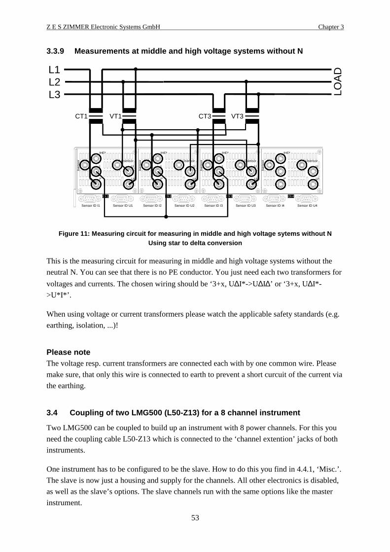
Z E S ZIMMER Electronic Systems GmbH Chapter 3
53
3.3.9 Measurements at middle and high voltage syste ms without N
L1
LOA
D
L2L3
CT1 CT3 VT3VT1
Usensor
Isen
sor
U*
IHF*
I*
I U
Usensor
Isen
sor
U*
IHF*
I*
I U
Usensor
Isen
sor
U*
IHF*
I*
I U
Usensor
Isen
sor
U*
IHF*
I*
I U
Sensor ID I1
Ch 1 Ch 2 Ch 3 Ch 4
Sensor ID I2 Sensor ID I3 Sensor ID I4Sensor ID U1 Sensor ID U2 Sensor ID U3 Sensor ID U4
Figure 11: Measuring circuit for measuring in middl e and high voltage sytems without NUsing star to delta conversion
This is the measuring circuit for measuring in middle and high voltage systems without the
neutral N. You can see that there is no PE conductor. You just need each two transformers for
voltages and currents. The chosen wiring should be ‘3+x, U∆I*->U ∆I∆’ or ‘3+x, U∆I*-
>U*I*’.
When using voltage or current transformers please watch the applicable safety standards (e.g.
earthing, isolation, ...)!
Please noteThe voltage resp. current transformers are connected each with by one common wire. Please
make sure, that only this wire is connected to earth to prevent a short curcuit of the current via
the earthing.
3.4 Coupling of two LMG500 (L50-Z13) for a 8 channe l instrument
Two LMG500 can be coupled to build up an instrument with 8 power channels. For this you
need the coupling cable L50-Z13 which is connected to the ‘channel extention’ jacks of both
instruments.
One instrument has to be configured to be the slave. How to do this you find in 4.4.1, ‘Misc.’.
The slave is now just a housing and supply for the channels. All other electronics is disabled,
as well as the slave’s options. The slave channels run with the same options like the master
instrument.

Installation LMG500
54
The additional channels are displayed in the master instrument as channels 5 to 8 and with the
new group identifiers ‘C’ and ‘D’. All the other handling is the same like in the basic
instrument.

Z E S ZIMMER Electronic Systems GmbH Chapter 4
55
4 Instrument controls
4.1 Front panel
1 2 3 4 5
6
7
8910111213Figure 12: Front panel of the instrument
1. Graphical Display
2. Softkeys
Their function depends on the indicated function in the display.
3. Rotary knob
This knob is used for several number settings, for selections in lists and for cursor moving.
A turn to the right increases the number. In many cases you can also push the knob to
confirm a selection.
4. ENTER key
This key is used to finish an entering and to quit an error message
5. ESC key
This key is used cancel an entering mode and to quit an error message.
6. Dark menu selection keys
With this keys you can call different menus with the pure measuring values:
Default, Current, Voltage, Power, Int. Value and Graph.
A second function of this keys is to enter the digits from ‘4’ to ‘9’ when in a number
entering mode.
7. Violet menu selection keys
With this keys you can call several menus for setting up the instrument:
Measure: The main measuring parameters
Int. Time: The parameters for time dependent measuring

Instrument controls LMG500
56
Custom: The set-up of the custom defined menus
Ranges: The range selection of the measuring channels
Misc.: Setup of date, time and display brightness.
IF/IO: Setup of options
A second function of this keys is to enter the digits from ‘0’ to ‘3’ and ‘.’ and ‘-’ when in a
number entering mode.
8. Floppy disk drive on older instruments. Alternatively there can be a USB memory stick
adapter instead of the floppy (option L50-O2USB) . This USB adapter can be used for
memory sticks only!
9. Special function keys
Status: Here you get status information about the LMG500
Start: This key is used to start time dependent measurements
Stop: This key is used to stop time dependent measurements
Save/Recall: The actual menu is stored to the memory card
Print/Log: The actual menu is send to the printer output or logger
Freeze: Holds the measuring values of the last cycle in the display or
enables the refresh of the display after each cycle
10. Special Function Key F3
11. Special Function Key F2
12. Special Function Key F1
13. Mains switch
4.2 Rear panel
Usensor
Isen
sor
U*
IHF*
I*
I U
Usensor
Isen
sor
U*
IHF*
I*
I U
Usensor
Isen
sor
U*
IHF*
I*
I U
Usensor
Isen
sor
U*
IHF*
I*
I U
Sensor ID I1
Analog/Digital I/O B IEEE488 COM B
COM A
Channel Extension
Printer
Power Supply85...265Vac47...64Hz/150W
Sync PS2 LAN USBAnalog/Digital I/O A
Ch 1 Ch 2 Ch 3 Ch 4
Sensor ID I2 Sensor ID I3 Sensor ID I4Sensor ID U1 Sensor ID U2 Sensor ID U3 Sensor ID U4
1
2
3
4
6
7 8 9 11 12 13
151617181920212223242526
10
5
Figure 13: Rear panel of the instrument

Z E S ZIMMER Electronic Systems GmbH Chapter 4
57
First measuring channel:
1. External voltage sensor identification
Identification input for external voltage sensors. It is used together with sensor adaptor
L50-Z14. 9-pin SUB-D socket.
2. External current sensor identification
Identification input for external current sensors. It is used together with sensor adaptor
L50-Z14. 9-pin SUB-D socket.
3. I*
Wide dynamic current input (high), 4mm violet safety socket
4. I
Current input (low), 4mm grey safety socket. This is the reference socket for the I*, IHF and
Isensor input.
5. Isensor
Voltage input for external current sensors (high), 4mm red safety socket.
6. IHF
High frequent current input (high), 4mm orange (violet at older instruments) safety socket
7. Usensor
Voltage input external voltage sensors (high), 4mm red safety socket.
8. U*
Voltage input (high), 4mm violet safety socket
9. U
Voltage input (low), 4mm grey safety socket. This is the reference socket for the U* and
Usensor input.
10. First measuring channel.
11. Second measuring channel with same sockets like first channel
12. Third measuring channel with same sockets like first channel
13. Fourth measuring channel with same sockets like first channel
14. Not used
15. Mains
Fused chassis plug with holder for fuses. Mains voltage 85...264V, 47...64Hz, up to 150W,
depending on installed options, 2 fuses T3.15A/250V, 5x20mm, IEC127-2/3
Instrument controls LMG500
58
16. PE
Connector for additional earthing, 4mm green/yellow safety socket
17. Channel extension
Here you can connect additional measuring channels from the extension box LMG500-E or
a second LMG500.
18. Printer
Centronics compatible interface or printer connection
25-pin SUB-D socket
19. ComB: Serial RS232 interface
This is a serial interface which can be used for remote control, but usually it is used for
special devices, like the LAN adaptor L50-Z318
9-pin SUB-D jack
20. ComA: Serial RS232 interface
This is the standard serial interface for remote control of the instrument.
This interface is also used for software updates and service purposes.
9-pin SUB-D socket
21. USB, option L50-02USB.
Jack for an USB cable with plug type B. This USB adapter can be used for remote
controlling only!
22. LAN, option L50-O2LAN
RJ45 socket for a LAN cable. This LAN can be used for remote controlling only!
23. PS/2
Connector for an external keyboard. This can be connected to enter for example formulas
in a comfortable way.
24. Sync.
Socket for external synchronisation and measuring time control of the instrument.
15-pin SUB-D socket
25. IEEE488
Parallel interface, 24-pin micro-ribbon socket
26. I/O card
Additional analogue and digital inputs and outputs for auxiliary signals. Two 25-pin
SUB-D sockets.

Z E S ZIMMER Electronic Systems GmbH Chapter 4
59
4.3 Display
The display is divided into 3 sections:
• The softkeys at the right border change their meaning depending on the actual menu. A
softkey with a black background is an active softkey. A dotted softkey can not be used.
• The elements of the status line at the top of the display are described in ‘4.3.1 Status line’.
In this line you can see the most important status information of the instrument. This line is
always visible.
• In the main display the different menues are displayed. This can be measuring values, set
up menues or graphs.
At the bottom of this region a possible error message is displayed. This error messages
have to be quit by pressing Enter or Esc.
4.3.1 Status line
Figure 14: Status line
The status line has the following sub sections (from left to right):
• The voltage and current signal level indicators. Here you can see how much of the actual
voltage/current range has been used. This display is important for the selection of the
measuring range. At the left side three information: The upper one is the group (A to D), in
the middle is synchronisation source of the channel. Here you can find:
Un for the voltage channel n
In for the current channel n
Li for line synchronisation
Ex for external synchronisation
As (inverse) for asynchronous (no synchronisation)
The lower information can be:
‘LF’ (inverse displayed ) indicating that the signal of the channel is low pass filtered.
• The mode indicator. In this line you see the chosen measuring mode. Possible values are
‘Normal’, ‘CE-Harm’, ‘CE-Flk’, ‘HRM100’ and ‘Trans’.
In the line below, the time base indicator shows the actual chosen cycle time. The bar
below this number shows how much of the cycle time is over.
• The ‘Active’ indicates, that the display is updated with measuring values. ‘Freeze’
indicated a frozen display. The current displayed values don’t change until ‘Active’ is
chosen again (key Freeze).
Below: the remote indicator. ‘Remote’ indicates that the instrument is remote controlled by
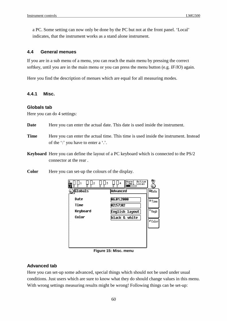
Instrument controls LMG500
60
a PC. Some setting can now only be done by the PC but not at the front panel. ‘Local’
indicates, that the instrument works as a stand alone instrument.
4.4 General menues
If you are in a sub menu of a menu, you can reach the main menu by pressing the correct
softkey, until you are in the main menu or you can press the menu button (e.g. IF/IO) again.
Here you find the description of menues which are equal for all measuring modes.
4.4.1 Misc.
Globals tabHere you can do 4 settings:
Date Here you can enter the actual date. This date is used inside the instrument.
Time Here you can enter the actual time. This time is used inside the instrument. Instead
of the ‘:’ you have to enter a ‘.’.
Keyboard Here you can define the layout of a PC keyboard which is connected to the PS/2
connector at the rear .
Color Here you can set-up the colours of the display.
Figure 15: Misc. menu
Advanced tabHere you can set-up some advanced, special things which should not be used under usual
conditions. Just users which are sure to know what they do should change values in this menu.
With wrong settings measuring results might be wrong! Following things can be set-up:

Z E S ZIMMER Electronic Systems GmbH Chapter 4
61
Zero The zero point rejection (see 12.2, ‘Display of values’) can be switched off. It
will be activated again each time you restart the instrument.
Phan. Vals. The rejection of phantom values can be deactivated. Phantom values appear for
example at wiring ‘3+1, U∆I*->U ∆I∆’, because the measured star current has
physically nothing to do with the measured triangle voltage. But the power
measuring channel sees both signals at the same time and calculates a power for
them, the phantom power.
Slave Defines this instrument as the slave in a Master/Slave configuration
Z-Adj. allows you to adjust the zero point of the instrument. You can only adjust the
actual selected voltage and current jacks.
You can reset the instrument to the factory settings of calibration by holding the
lower two softkeys pressed while switching on the instrument (for about 10s,
until the instrument beeps).
Be careful with this function because you can also deadjust theinstrument!!!For the exact adjustment steps please refer to 11.3.3 ‘Zero adjustment of the
instrument’.
4.4.2 IF/IO
In this menu you can set-up all features which are available as instrument options. Further on
you see the actual software version and the installed options. With List you can choose a short
list or detail list. In the last one you can scroll with the rotary knob.
4.4.2.1 Interfaces for remote control
With exception of the IEEE interface all interfaces could also be used for data logging (see 10,
‘Logging of values to drives, printer and interfaces’. To remote control the LMG you first
have to set-up the wished interface for this job.
Press several times IF/IO to reach the IF/IO menu. By pressing IF you can set-up the remote
device. You have several available ‘profiles’ from which you can select one (with Dev.).These profiles are predefined but they can be modified when necessary (with Set).
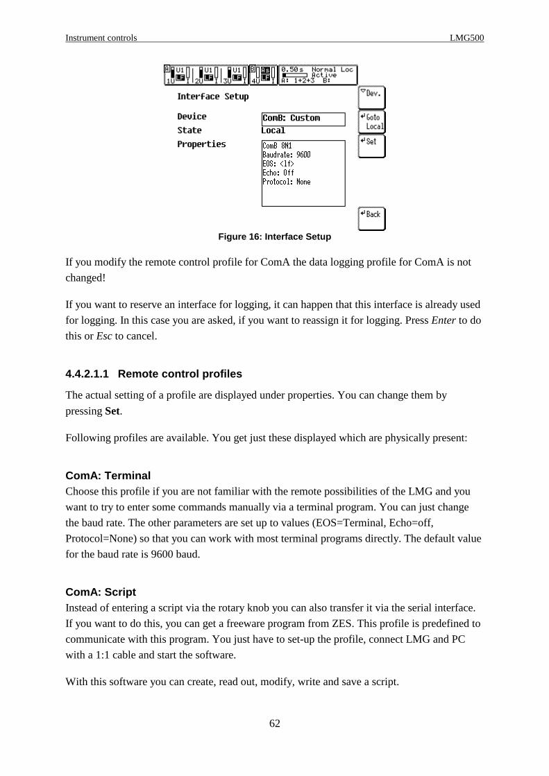
Instrument controls LMG500
62
Figure 16: Interface Setup
If you modify the remote control profile for ComA the data logging profile for ComA is not
changed!
If you want to reserve an interface for logging, it can happen that this interface is already used
for logging. In this case you are asked, if you want to reassign it for logging. Press Enter to do
this or Esc to cancel.
4.4.2.1.1 Remote control profiles
The actual setting of a profile are displayed under properties. You can change them by
pressing Set.
Following profiles are available. You get just these displayed which are physically present:
ComA: TerminalChoose this profile if you are not familiar with the remote possibilities of the LMG and you
want to try to enter some commands manually via a terminal program. You can just change
the baud rate. The other parameters are set up to values (EOS=Terminal, Echo=off,
Protocol=None) so that you can work with most terminal programs directly. The default value
for the baud rate is 9600 baud.
ComA: ScriptInstead of entering a script via the rotary knob you can also transfer it via the serial interface.
If you want to do this, you can get a freeware program from ZES. This profile is predefined to
communicate with this program. You just have to set-up the profile, connect LMG and PC
with a 1:1 cable and start the software.
With this software you can create, read out, modify, write and save a script.
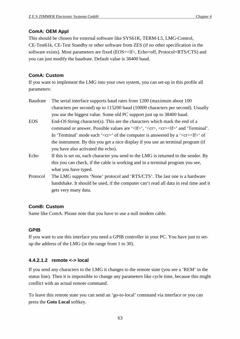
Z E S ZIMMER Electronic Systems GmbH Chapter 4
63
ComA: OEM ApplThis should be chosen for external software like SYS61K, TERM-L5, LMG-Control,
CE-Test61k, CE-Test Standby or other software from ZES (if no other specification in the
software exists). Most parameters are fixed (EOS=<lf>, Echo=off, Protocol=RTS/CTS) and
you can just modify the baudrate. Default value is 38400 baud.
ComA: CustomIf you want to implement the LMG into your own system, you can set-up in this profile all
parameters:
Baudrate The serial interface supports baud rates from 1200 (maximum about 100
characters per second) up to 115200 baud (10000 characters per second). Usually
you use the biggest value. Some old PC support just up to 38400 baud.
EOS End-Of-String character(s). This are the characters which mark the end of a
command or answer. Possible values are ‘<lf>‘, ‘<cr>, <cr><lf>‘ and ‘Terminal’.
In ‘Terminal’ mode each ‘<cr>‘ of the computer is answered by a ‘<cr><lf>‘ of
the instrument. By this you get a nice display if you use an terminal program (if
you have also activated the echo).
Echo If this is set on, each character you send to the LMG is returned to the sender. By
this you can check, if the cable is working and in a terminal program you see,
what you have typed.
Protocol The LMG supports ‘None’ protocol and ‘RTS/CTS’. The last one is a hardware
handshake. It should be used, if the computer can’t read all data in real time and it
gets very many data.
ComB: CustomSame like ComA. Please note that you have to use a null modem cable.
GPIBIf you want to use this interface you need a GPIB controller in your PC. You have just to set-
up the address of the LMG (in the range from 1 to 30).
4.4.2.1.2 remote <-> local
If you send any characters to the LMG it changes to the remote state (you see a ‘REM’ in the
status line). Then it is impossible to change any parameters like cycle time, because this might
conflict with an actual remote command.
To leave this remote state you can send an ‘go-to-local’ command via interface or you can
press the Goto Local softkey.
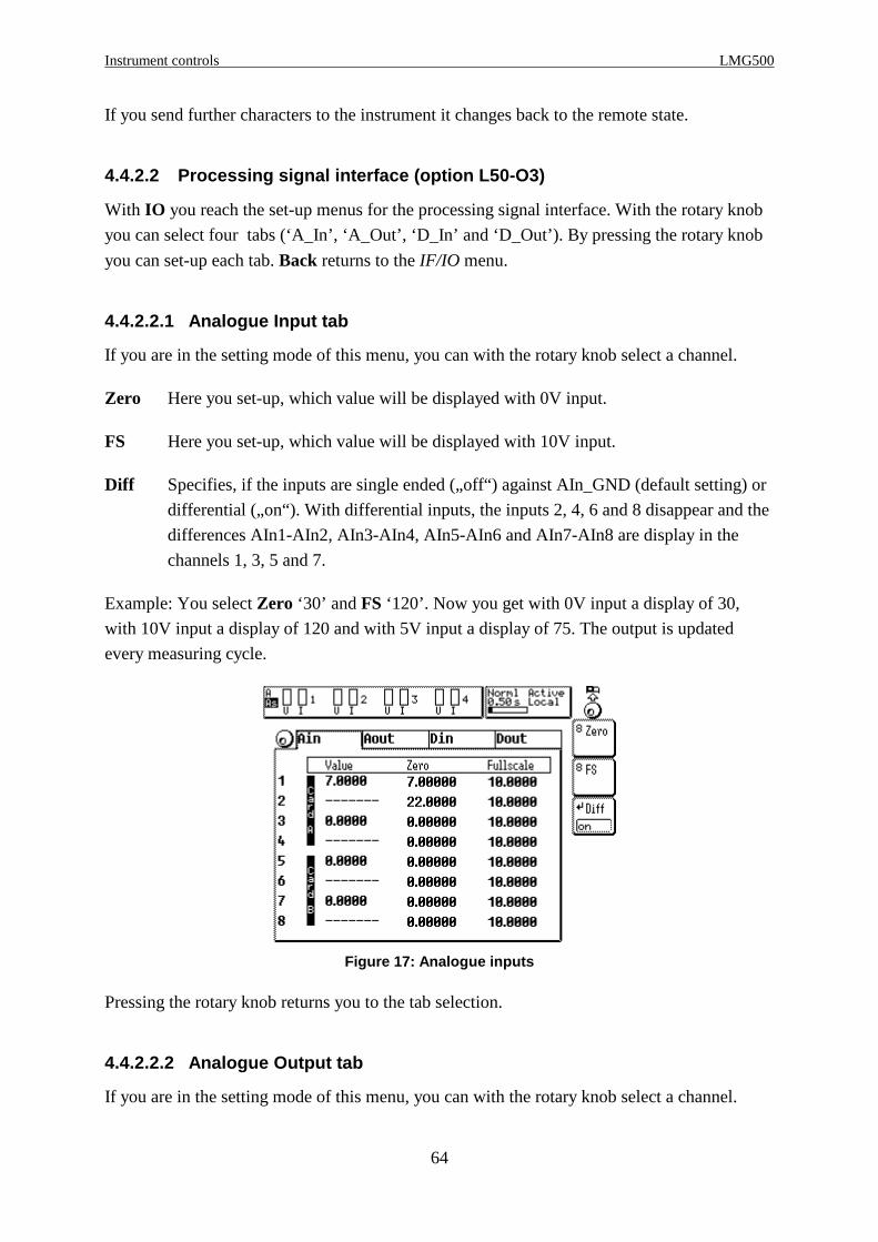
Instrument controls LMG500
64
If you send further characters to the instrument it changes back to the remote state.
4.4.2.2 Processing signal interface (option L50-O3)
With IO you reach the set-up menus for the processing signal interface. With the rotary knob
you can select four tabs (‘A_In’, ‘A_Out’, ‘D_In’ and ‘D_Out’). By pressing the rotary knob
you can set-up each tab. Back returns to the IF/IO menu.
4.4.2.2.1 Analogue Input tab
If you are in the setting mode of this menu, you can with the rotary knob select a channel.
Zero Here you set-up, which value will be displayed with 0V input.
FS Here you set-up, which value will be displayed with 10V input.
Diff Specifies, if the inputs are single ended („off“) against AIn_GND (default setting) or
differential („on“). With differential inputs, the inputs 2, 4, 6 and 8 disappear and the
differences AIn1-AIn2, AIn3-AIn4, AIn5-AIn6 and AIn7-AIn8 are display in the
channels 1, 3, 5 and 7.
Example: You select Zero ‘30’ and FS ‘120’. Now you get with 0V input a display of 30,
with 10V input a display of 120 and with 5V input a display of 75. The output is updated
every measuring cycle.
Figure 17: Analogue inputs
Pressing the rotary knob returns you to the tab selection.
4.4.2.2.2 Analogue Output tab
If you are in the setting mode of this menu, you can with the rotary knob select a channel.

Z E S ZIMMER Electronic Systems GmbH Chapter 4
65
Value This allows you to set-up the value which should be output. See chapter 4.5,
‘Entering identifiers’ for details.
Zero Here you set-up, which value of Value will result an output of 0V.
FS Here you set-up, which value of Value will result an output of 10V.
Figure 18: Analogue outputs
Example1: You select Value ‘Utrms’, Zero ‘200’ and FS ‘250’. Now you get with
Utrms=200V an output of 0V, with Utrms=250V an output of 10V and with Utrms=230V an
output of 6V. The output is updated every measuring cycle, because the values are calculated
every measuring cycle.
Pressing the rotary knob returns you to the tab selection.
4.4.2.2.3 Digital Inputs tab
In this menu you get the actual state of the digital inputs. The inputs 1 to 4 of each card are
only used for state indication. The inputs 5 and 6 can be used as state indicators or for
frequency and direction input (determined by the phase shift between input 5 and 6). In the
last case the input 5 is used to measure the frequency. This is multiplied with the ‘Scale’ value
and displayed under ‘Frequency’. A negative frequency value indicates a reverse rotation
direction. To change the scaling press the rotary knob and Scl.A (or Scl.B for the card B).
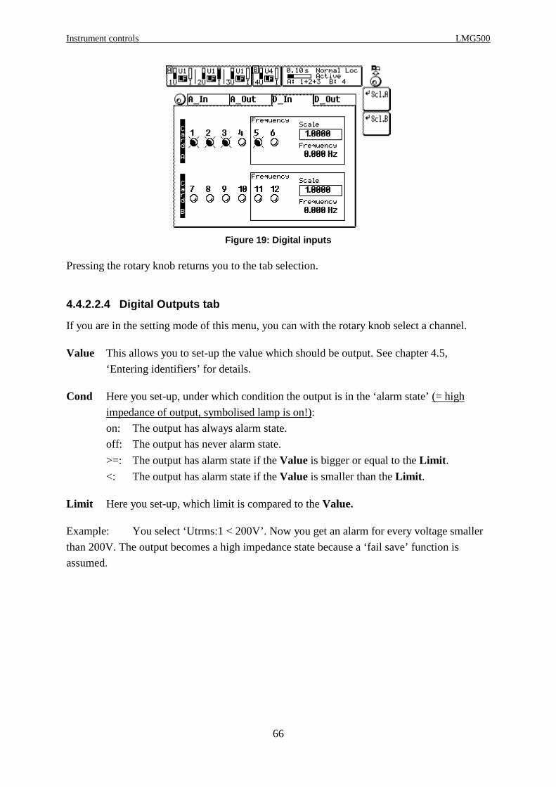
Instrument controls LMG500
66
Figure 19: Digital inputs
Pressing the rotary knob returns you to the tab selection.
4.4.2.2.4 Digital Outputs tab
If you are in the setting mode of this menu, you can with the rotary knob select a channel.
Value This allows you to set-up the value which should be output. See chapter 4.5,
‘Entering identifiers’ for details.
Cond Here you set-up, under which condition the output is in the ‘alarm state’ (= high
impedance of output, symbolised lamp is on!):
on: The output has always alarm state.
off: The output has never alarm state.
>=: The output has alarm state if the Value is bigger or equal to the Limit .
<: The output has alarm state if the Value is smaller than the Limit .
Limit Here you set-up, which limit is compared to the Value.
Example: You select ‘Utrms:1 < 200V’. Now you get an alarm for every voltage smaller
than 200V. The output becomes a high impedance state because a ‘fail save’ function is
assumed.

Z E S ZIMMER Electronic Systems GmbH Chapter 4
67
Figure 20: Limit menu
Pressing the rotary knob returns you to the tab selection.
Fail Save PrincipleThe fail save principle should offer you highest safety in critical applications. The principle is,
that a high impedance state is the alarm (active) state. By this also broken or not connected
wires as well as not switched on instruments are recognized as fail. Only the low impedance
state is recognized as no alarm (deactive).
4.4.2.3 Options key
If you press on the softkey with the key symbol you get an actual software key which
represents all installed options in your instrument. Some options of the instrument are
software options which can be released by another key. If you for example want to install the
100 Harmonics you send us or your local sales company an order about this option together
with your Current Option Key and with your serial number (SN).
Then you get back a second key which you can enter after pressing the key symbol. If the
second key is correct, the option is installed.
NoteIf you can access the instrument via an interface, you can use LMG-CONTROL to read out
and update the key. This is much easier than working with the front panel.
4.4.3 Custom menu
In the standard menus Voltage, Current, ... (see chapters below) we have defined some values
to be displayed which should fit to most customers. For some special applications you can
define in the Custom menu your own values and graphics which should be displayed. Further
Instrument controls LMG500
68
on you can define your own values by using the integrated script editor (see 4.4.4,
‘Script/Formula editor’).
When entering you get at least two tabs. To change between the tabs, you have to use the
rotary knob. To get the softkeys inside a tab you have to press the rotary knob.
4.4.3.1 New menu tab
Here you first have to define the name of a new (user defined) tab with Name. Then you have
to define the mask for the menu with Form. Depending on this mask you can define up to 50
values for a menu. If everything is finished you can create the new menu by pressing Makenew. The new menu appears as a new tab which can be edit (see 4.4.3.3, ‘User defined tab’).
You can define up to 8 menus.
With Load you can recall a previously saved menu from memory card or floppy if installed.
You have to select a filename from the list.
4.4.3.2 Vars tab
In the Vars tab you see all variables. By default they are named ‘var0’ to ‘var11’. With Resetyou can set them all to ‘0.0’.
4.4.3.3 User defined tab
Here you do the definitions, which values appear at which place. With the rotary knob you
choose the position an press Edit Item . In the dialog you choose with Typ the kind of data do
display:
empty The item will displayed blank. Choosing this is the same like pressing the
Del Item softkey.
Value When choosing this have to choose with Prop a measuring value which
should be displayed as value with unit, but without identifier. How to enter
the Prop value see 4.5, ‘Entering identifiers, characters and text’.
Name+Value When choosing this have to choose with Prop a measuring value which
should be displayed as value with unit and with leading identifier. How to
enter the Prop value see 4.5, ‘Entering identifiers, characters and text’.
String When choosing this have to choose with Prop a text which should be
displayed. How to enter the Prop value see 4.5, ‘Entering identifiers,
characters and text’.
Graph Here you get a list of all possible graphs. In principle you can display copies
of graphs which you have already set-up in the Graph menu. ‘Scp.A:1’
selects the first waveform of the group A scope, ‘Scp.B:3’ the third

Z E S ZIMMER Electronic Systems GmbH Chapter 4
69
waveform of group B scope. The ‘Plot:x’ is for selecting one of the four plot
functions.
To modify the graphical display you have to change to the Graph menu.
With Font you can choose another than the predefined font for the display.
With Copy menu you create a copy of the complete tab which can then be modified. With
Del menu you can remove the complete tab. In a pop up menu you have to confirm this a
second time.
To give a menu another name, please use Edit Name.
With Save you can store the menu to a memory card or floppy if installed. You have to select
a filename from the list or enter a new one with File name.
4.4.4 Script/Formula editor
You reach the script/formula editor by pressing Edit in ‘Script’ tab in Custom menu.
With Edit you start entering the script. This is done like written in 4.5, ‘Entering identifiers,
characters and text’.
Figure 21: Script editor
With Save you can store the script to a memory card or floppy if installed. You have to select
a filename from the list or enter a new one with File name.
With Load you can recall a previously saved script.
4.4.4.1 General
The script editor is similar like a simple programming language. The code is entered line by
line. It is allowed to have several instructions in one line. Each instruction has to end with a
‘ ; ’. Therefore an instruction can be written in more than one line. It is also allowed to have
Instrument controls LMG500
70
white spaces in the instruction as long as the keywords and identifiers are not divided by them.
At the end of a line an automatic carriage return and linefeed are performed. A ‘#’ indicates
the begin of a comment. The comment lasts, until a return is detected (can be entered with
new line). An automatic inserted newline will NOT end the comment!
The instruction
v0=Utrms*Itrms;
is identical to
v0 = Utrms* Itrms ;
or
v0 =Utrms * Itrms;
<- deletes the character left of the cursor. If the cursor is at the first position of a line, it jumps
to the last position of the previous line.
You leave the script editor by pressing End. The program is now checked for correct syntax.
Above the editor window you see then how many percent of the available memory space have
been used.
The script (which includes the formulas) is executed when all values of a cycle have been
calculated.
With Reset all variables are preset to 0.0 but the script is still valid. This is important if you
use recursive formulas or conditions.
4.4.4.2 Grammar
4.4.4.2.1 Instructions
Instructions control the program flow while execution. If there are no conditioned instructions,
the flow is in the same order like the listing. The results of an instruction can be used
afterwards.
An instruction consists of one or more expressions. Each instruction (except if , else and fi )
has to be finished with ‘; ’. An instruction can be longer than one line. The result must not be
assigned to a variable.
4.4.4.2.2 Condition instruction
Condition instructions choose between two alternative program flows. This is done by the
expression following immediately to the word if .
Z E S ZIMMER Electronic Systems GmbH Chapter 4
71
if(expression) Instructions; fiorif(expression) Instructions; else Instructions; fi
The brackets for the expression are necessary. Then there could be one or more semicolon
separated instructions which are executed if the expression was true. The end of the
conditional execution is marked with fi , which is also necessary. The else part is optional.
Condition instructions can be nested, for example to realise a logical AND:
if(expression1) if(expression2) Instruction 1; : Instruction n; fifi
Exampleif (Utrms>227.5) dout_off(1); dout_off(2);else dout_on(4);fi
If the voltage is bigger than 227.5V the digital outputs 1 and 2 are set to off. In the other case
the output 4 is set to on.
4.4.4.2.3 Expressions
An expression is a sequence of operators, operands and functions. Expressions are in general
recursive, which means they can be nested. But there is a practical limit in CPU power and
memory which can cause the message „out of memory“.
The order of evaluation of an expression depends on the priority of operands and on the
brackets (see below).
4.4.4.2.4 Constants
Constants are always floating point. The valid range is ±3.4E-34 to ±3.4E+34. The number
can be entered in usual or scientific notation. The decimal dot is only necessary for floating
point numbers.
4.4.4.2.5 Variables
There is a distinction between read only variables and read write variables. The first ones are
all measuring values of the LMG but also values like cycle time and measuring ranges. This
variables can be used for calculation like constants. The second one are the user defined
variables.
So following is o.k.
v0=Utrms;

Instrument controls LMG500
72
but
Utrms=0;
is not allowed.
A unit can be assigned to the variable. To assign the unit ‘cm’ to the varaible ‘a’ write:a.cm=...
The result of expressions can only be stored in the user defined variables with the default
identifiers ‘var0’ to ‘var11’. This identifiers are valid until they are redefined in a script. The
redefinition is simply be done by using a not existing identifier. This identifier replaces the
first variable which was not changed until now. The maximum length of the new identifier is
10 characters. In ‘Example 2’ the identifier Uhigh replaces the identifier var0 and Ulow
replaces var1 . As you can see the identifiers are replaced in the order of the occurrence. If you
press End, all occurrences of var0 are replaced with Uhigh and so on. So you get in the user
defined menu or the plot menu the new identifiers.
The read-only variables are identical to the identifiers in the menus (see 4.5, ‘Entering
identifiers’.
4.4.4.2.5.1 Local variables
A third kind of variables are local variables. They are also user defined, but are not displayed
in the custom menu. A local variable starts always with a ‘$’ character:
$test=Utrms*19.234;b=Iac*$test;
In this example $test is not displayed, but only b.
4.4.4.2.5.2 Environment variables
These variables are accessible via the ‘Env’ ID as an array: Env[0...7] .
They are (in opposite to standard variables) not displayed, but they can (in opposite to local
variables) be used externally (e.g. in the processing signal interface). Further on they can be
set directly by the interface (see 9.2.2.1.1, ‘ENVironment ENV Env’).
4.4.4.2.6 Keywords
These are strings which are no variables or constants but which are used for controlling the
script editor:
if The start of a conditioned program sequence. The condition have to follow in the
round brackets.
Z E S ZIMMER Electronic Systems GmbH Chapter 4
73
else The end of the program sequence which is used if the condition of the if was true (no
semicolon at the end!). All command after the else until the next fi are used, if the
condition of the if was not true. The else is optional.
fi The end of the program sequence which is used if the condition of the if was true (no
semicolon at the end!).
4.4.4.2.7 Functions
The following functions are implemented at the moment (x is the result of a valid expression,
constant or function):
abs(x) absolute value of x
acos(x) arcus cosine of x (result in radiant!)
asin(x) arcus sine of x (result in radiant!)
bell() generates a short sound with the internal speaker
btst(x, bit_no) Returns true, if in variable x bit number bit_no is set. The bits are counted
from 1 to 32. You should only apply this function onto integer values like
digital inputs or result of flicker measuring. Usually you should not use it
with float numbers.
cos(x) cosine of x (argument in radiant!)
digin(mask) Returns the value of the digital inputs. The values are coded in one byte:
input 1-4 correspond to bit 0-3 and input 7-10 to bit 4-7. So if the inputs 1
and 8 are active, the returned value would be 33. With mask you can
define, which values are checked: With a mask of 32 only the input 8 is
checked. In this case the return value can only be 32 or 0. The mask is
useful when checking the status of one input, independent from the others.
If you want to check all inputs, you should use a mask of 255!
dout_off(nr) Switches digital output number nr. off (into no-alarm state). 1≤nr≤8
dout_on(nr) Switches digital output number nr on (into alarm state). 1≤nr≤8
freeze() freezes the display (like key Freeze)
isrun() Returns 1, if the integration is running
isstop() Returns 1, if the integration is stopped
Instrument controls LMG500
74
ln(x) loge of x
log(x) log10 of x
print() Prints the menu in which you started the logging in ‘by script’ mode (see
10.3.1, ‘Output intervals’).
reset() Same like Reset Softkey in Time Int. menu
scale_i(chn,x) Scale the current input, chn. is the number of the channel, x the scaling
factor.
scale_u(chn,x) Scale the voltage input, chn. is the number of the channel, x the scaling
factor.
sin(x) sine of x (argument in radiant!)
sqrt(x) The square root of x
start() Same like pressing Start
stop() Same like pressing Stop
unfreeze() reactivates the frozen display
4.4.4.2.8 Operators
Operators are symbols which cause actions, when they meet variables, constants or formulas.
The script editor offers following operators, sorted by priority:
high priority
: Channel separator, usually used only for multi channel devices (like analogue
inputs). E.g. Ain:3 is the third analogue input channel.
[ ] Index operator, used for indexed values (arrays), e.g. U[5] is the 5th harmonic of the
voltage
() Function call, the value inside the brackets is the parameter to the function
- Negation
^ Exponent
/ * Division and Multiplication
+ - Addition and Subtraction

Z E S ZIMMER Electronic Systems GmbH Chapter 4
75
<, ==, > smaller, equal, bigger (comparator operators)
= Assignment of a value
<> not equal
low priority
If there are no brackets, the operators are used in the order listed above.
The result of:
3^2*4 is 36
-(3^2)*-4 is also 36
4.4.4.2.9 Remarks
Each line starting with a ‘#’ is a remark. See ‘4.4.4.2.14 ,Example 5:Switching digital outputs,
depending on harmonics’. Only the first ‘#’ is important, the other don’t care.
4.4.4.2.10 Example 1: Freeze at limit violation
If the 23rd harmonic of voltage of channel 1 is bigger than 10V the display should be frozen
and the instrument should inform you with a sound.
if(Uh:1[23] > 10) freeze(); bell();fi
Attention!The function freeze() can cause the display to freeze at the start-up of the instrument. So be
careful when using this function.
4.4.4.2.11 Example 2: Getting min/max values
You want to measure the biggest and smallest TRMS values of the voltage.
if (Uhigh==0) Ulow=RngU:1;fiif (Uhigh<Utrms:1) Uhigh=Utrms:1;fiif (Ulow>Utrms:1) Ulow=Utrms:1;fi
The first if condition is used for resetting the minimum value: With Reset it would be set to 0
which is not sufficient, because this is already the smallest TRMS value. So if the maximum
TRMS value is reset to 0.0, the minimum value is set to the range value which will not be
Instrument controls LMG500
76
reached under proper conditions. The second and third condition compute the maximum and
minimum value and store them in the variables Uhigh and Ulow which can be read out in the
Custom menu.
4.4.4.2.12 Example 3: Calculating THD+N
You want to measure the total distortion factor including noise (THD+N) of the voltage of
channel 2:
THDN=sqrt((Utrms:2^2-Uh:2[1]^2)/Uh:2[1]^2);
Please note that this will only work in the harmonic mode, because Uh:2[1] is only calculated
there!
4.4.4.2.13 Example 4: Counting pulses
You want to count the number of current pulses of a battery above 3A (the pulse width has to
be bigger than twice the cycle time!)
ibat=abs(Idc:1);if (ibat>3.0) if (r == 0) n=n+1; r=1; fifiif (ibat < 3.0) r=0;fi
4.4.4.2.14 Example 5:Switching digital outputs, dep ending on harmonics
### Wave1 ###if(Ih:1[1]>0.08) dout_on(1);else dout_off(1);fi### Wave3 ###if(Ih:1[3]>0.068) dout_on(2);else dout_off(2);fi### Wave5 ###if(Ih:1[5]>0.05) dout_on(3);else dout_off(3);fi
The digital outputs 1 to 3 are switched on if the corresponding harmonic 1 to 5 is bigger than a
defined value. In the other case the output is switched off.
4.4.4.2.15 Example 6: Calculation of the efficiency of a motor with torque andfrequency input
For the measurement of the efficiency of a motor you can use the analogue and the frequency
inputs. To input the torque of the motor use the analogue input (e.g. 1) and for the frequency
use the digital frequency input (e.g. card1 Pin 12). For calculation of the efficiency you can
use the following formula:
Z E S ZIMMER Electronic Systems GmbH Chapter 4
77
M=Ain:1;n=DigFrq:1;Pmech=M*n;eta=Pmech/P:13*100;
Important Note: The motor frequency connected to the frequency input (No.1) has to be
counted and scaled in Hz. Then you get a result in percent.
4.4.4.3 Printing scripts
You can printout the scripts you have set-up (see 10, ‘Logging of values to drives, printer and
interfaces’). Please note, that the complete script editor is printed out, not only the visible part.
4.4.4.4 Speed and torque calculation (option MotorT orque-SOFT)
This option provides two functions which calculate the values speed and torque from motor
current and voltage. The motor must be a three phase asynchronous standard motors according
IEC. There are just some information from type plate or catalogue data necessary. There is no
need of a torque measuring shaft or a speed sensor. The motor can be connected to the lines or
to a frequency converter.
Measuring error between no-load operation and 1.5 fold nominal torque typical below 2% of
nominal torque resp. rotation speed for motors from 1kW to 100kW nominal power and
rotation speed between -40% to +20% of nominal speed. The calculation is also possible with
other nominal power, but with increased error.
For the calculation, following requirements must be met:
• Wiring
3+x, U∆I*->U*I*
• Filter
Smaller than half clock frequency. So just the fundamental must be measured, the clock
ripple must be rejected.
• Signal coupling
AC
• Sync
Such, that the fundamental frequency is displayed (e.g. I1, LP<300Hz)
The two functions are:
Instrument controls LMG500
78
torque(Pn, fn, Un, In, pfn, pz, Rk, sc, mk) Calculates the torque in Nm. The
parameters are:
Pn: Nominal output power in W
fn: Nominal frequency in Hz
Un: Nominal line line voltage of the
motor
in V
In: Nominal current in A
pfn: Nominal power factor
pz: Number of poles (twice the number of
pole pairs)
Rk: Stator line-line copper resistance in Ωsc: Number of the sum channel,
here 15 or 17
mk No load torque correction
speed(Pn, nn, fn, Un, In, pfn, pz, Rk, sc,mk)
Calculates the speed in min-1. The
parameters are:
Pn: Nominal output power in W
n: Nominal speed in min-1
fn: Nominal frequency in Hz
Un: Nominal line line voltage of the
motor
in V
In: Nominal current in A
pfn: Nominal power factor
pz: Number of poles (twice the number of
pole pairs)
Rk: Stator line-line copper resistance in Ωsc: Number of the sum channel,
here 15 or 17
mk No load torque correction
The copper resistance has to be measured at the same point, where the voltage is measured by
the LMG. The advantage is, that you can measure for example from a cabinet and that the
copper resistance of the wiring is included and by this eliminated from the calculation.
The results of torque() and speed() can be displayed in a user defined menu or transfered via
an interface.
A typical script could look like this:
# M-n-calculation
Z E S ZIMMER Electronic Systems GmbH Chapter 4
79
# Detailed motor description# 2.2kW Motor DDA 90 L# Input of the motor parameters$cn=0.84; # Nominal powerfactor$nn=2845; # Nominal speed 1/min$pz=2; # Number of poles # (2* pole pairs)$jn=4.66; # Nominal current in A$un=400; # Nominal L-L voltage in V$pn=2200; # Nominal output power in W$fn=50; # Nominal frequency in Hz$rk=19.7; # resistor in Ohm # terminal to terminal # (hot resistor)$mk=20; # No load torqueM.Nm=torque($pn,$fn,$un,$jn,$cn,$pz,$rk,15,mk);n=speed($pn,$nn,$fn,$un,$jn,$cn,$pz,$rk,15,mk);
No load torque correctionSet mk=0, enter all other data and make a no load measurement of the motor. Use the read out
torque with opposite sign as new value for mk. By this tolerances of the motor nominal values
are corrected.
4.4.5 Saving and restoring configurations
You can save up to 8 different set-ups for the instrument. With Reset you get the factory
settings. Everything is reset, but not the 8 stored configurations.
4.4.5.1 Loading a configuration
After pressing Save/Recall you can load previously saved configurations. For this purpose
choose the wanted one with the rotary knob and press Recll. All set-up values like range
settings, scripts and measuring settings are restored. The actual settings are lost.
In the field ‘Active configuration mod()’ you see now the name of the selected configuration.
If mod(*) is displayed, any of the settings are changed.
4.4.5.2 Saving the configuration
After pressing Save/Recall you can save the actual configuration. For this purpose choose the
wanted position with the rotary knob and press Save. Now you have to specify a name for this
entry (see chapter 4.5, ‘Entering identifiers, characters and text’). If the entry exists, it will be
overwritten. All setup values like range settings, scripts and measuring settings are saved.
4.5 Entering identifiers, characters and text
In some menus (e.g. in the plot menu or in the menu for the digital outputs) you have to enter
an identifier or text to specify which value should be worked with (e.g. plotted).
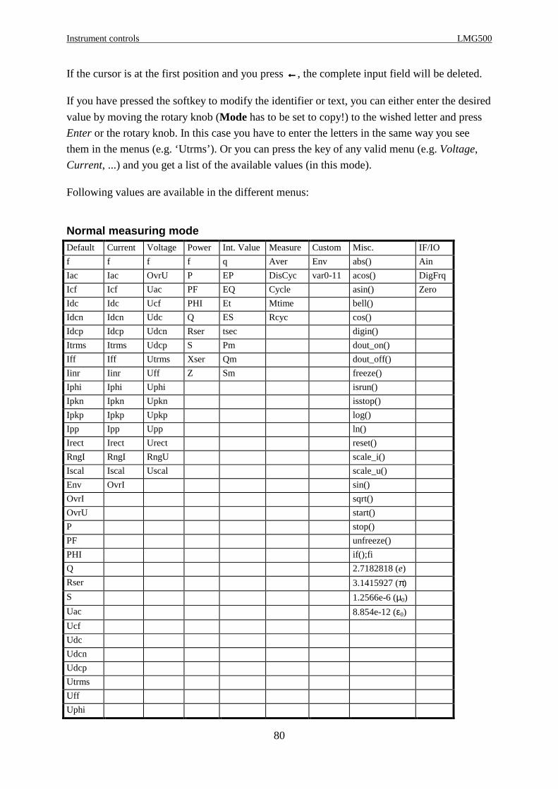
Instrument controls LMG500
80
If the cursor is at the first position and you press ←←←←, the complete input field will be deleted.
If you have pressed the softkey to modify the identifier or text, you can either enter the desired
value by moving the rotary knob (Mode has to be set to copy!) to the wished letter and press
Enter or the rotary knob. In this case you have to enter the letters in the same way you see
them in the menus (e.g. ‘Utrms’). Or you can press the key of any valid menu (e.g. Voltage,
Current, ...) and you get a list of the available values (in this mode).
Following values are available in the different menus:
Normal measuring modeDefault Current Voltage Power Int. Value Measure Custom Misc. IF/IO
f f f f q Aver Env abs() Ain
Iac Iac OvrU P EP DisCyc var0-11 acos() DigFrq
Icf Icf Uac PF EQ Cycle asin() Zero
Idc Idc Ucf PHI Et Mtime bell()
Idcn Idcn Udc Q ES Rcyc cos()
Idcp Idcp Udcn Rser tsec digin()
Itrms Itrms Udcp S Pm dout_on()
Iff Iff Utrms Xser Qm dout_off()
Iinr Iinr Uff Z Sm freeze()
Iphi Iphi Uphi isrun()
Ipkn Ipkn Upkn isstop()
Ipkp Ipkp Upkp log()
Ipp Ipp Upp ln()
Irect Irect Urect reset()
RngI RngI RngU scale_i()
Iscal Iscal Uscal scale_u()
Env OvrI sin()
OvrI sqrt()
OvrU start()
P stop()
PF unfreeze()
PHI if();fi
Q 2.7182818 (e)
Rser 3.1415927 (π)
S 1.2566e-6 (µ0)
Uac 8.854e-12 (ε0)
Ucf
Udc
Udcn
Udcp
Utrms
Uff
Uphi

Z E S ZIMMER Electronic Systems GmbH Chapter 4
81
Default Current Voltage Power Int. Value Measure Custom Misc. IF/IO
Upkn
Upkp
Upp
Urect
RngU
Uscal
var0-11
Xser
Z
CE-Harm Harmonic measuring modeDefault Current Voltage Power Measure Custom Misc. IF/IO
f f f f Per Env abs() Ain
Ih Ih Uh Ph Mtime var0-11 acos() DigFrq
Imav Imav Uthd Pav asin() Zero
Iav Iav UL PFm bell()
Ifm Ifm UMax Qh cos()
Ithd Ithd UP Sh digin()
IL IL OvrU P dout_on()
Im Im Utrms PF dout_off()
IP IP RngU Q freeze()
Ipohl Ipohl Rser isrun()
Ph Ipohc S isstop()
Pav Ithc Xser log()
PFm Itrms Z ln()
Ipohc RngI reset()
Qh Iscal scale_i()
Sh OvrI scale_u()
Ithc sin()
Uh sqrt()
Uthd start()
UL stop()
UMax unfreeze()
UP if();fi
Itrms 2.7182818 (e)
RngI 3.1415927 (π)
Iscal 1.2566e-6 (µ0)
Env 8.854e-12 (ε0)
OvrI
OvrU
P
PF
Q
Rser
S
Utrms

Instrument controls LMG500
82
Default Current Voltage Power Measure Custom Misc. IF/IO
RngU
Uscal
var0-11
Xser
Z
CE Flicker measuring modeDefault Current Voltage Power Int. Value Measure Custom Misc. IF/IO
Uhwcf f Uhwcf Phw Uhwcf Per Env abs() Ain
dcl dcs dcl f dcl Mtime var0-11 acos() DigFrq
dtl dts dtl P dmaxl FlkPer asin() Zero
dmaxl dmaxs dmaxl PF Pltl bell()
Pltl Plts Pltl Q Pmoml cos()
Pmoml Pms Pmoml Rser Pstl digin()
Pml Pmoms Pml S Upkph dout_on()
Phw Uhws Phw Xser dout_off()
Uhwl Psts Uhwl Z freeze()
Pstl Ithd Pstl isrun()
Upkph Itrms Upkph isstop()
f RngI f log()
dcs Iscal Uthd ln()
dts OvrI OvrU reset()
dmaxs Utrms scale_i()
Plts RngU scale_u()
Pms Uscal sin()
Pmoms sqrt()
Uhws start()
Psts stop()
Ithd unfreeze()
Uthd if();fi
Itrms 2.7182818 (e)
RngI 3.1415927 (π)
Iscal 1.2566e-6 (µ0)
Env 8.854e-12 (ε0)
OvrI
OvrU
P
PF
Q
Rser
S
Utrms
RngU
Uscal
var0-11

Z E S ZIMMER Electronic Systems GmbH Chapter 4
83
Default Current Voltage Power Int. Value Measure Custom Misc. IF/IO
Xser
Z
HARM100 measuring modeDefault Current Voltage Power Measure Custom Misc. IF/IO
D f f D Per Env abs() Ain
f Ih Uh f Mtime var0-11 acos() DigFrq
Ih Ithd Uthd Ph asin() Zero
Ithd IP UP Qh bell()
IP Itrms Utrms Sh cos()
Ph RngI RngU P digin()
Qh Iscal Uscal PF dout_on()
Sh OvrI OvrU Q dout_off()
Uh Rser freeze()
Uthd S isrun()
UP Xser isstop()
Itrms Z log()
RngI ln()
Iscal reset()
Env scale_i()
OvrI scale_u()
OvrU sin()
P sqrt()
PF start()
Q stop()
Rser unfreeze()
S if();fi
Utrms 2.7182818 (e)
RngU 3.1415927 (π)
Uscal 1.2566e-6 (µ0)
var0-11 8.854e-12 (ε0)
Xser
Z
Select one value with the rotary knob and press Enter or the rotary knob to copy the list item
into the edit line. If you have a multi channel value (e.g. analogue inputs) you have to enter a
‘:’ behind this value and then the number of the channel (e.g. the identifier for the analogue
input 3 would be ‘Ain:3’). If you don’t specify this number, ‘1’ is the default value. Confirm
your choice with Enter.
If the value is an array value, the desired index is entered in brackets ‘[‘ and ‘]’ (example the
5th harmonic of the voltage would be Uh[5]). You can also combine this values: Uh:2[5]
would be the 5th harmonic of the voltage of the second channel. If you don’t specify this
number, ‘0’ is the default value. Confirm your choice with Enter.

Instrument controls LMG500
84
To select another position in the text, you have to set Mode to ‘move’ or ‘line’. With ‘move’
you move character by character, with ‘line’ you move line by line, which is much faster in
bigger text.
With new line you can insert a linefeed (if you have a multi line input box). Especially in
conjunction with the script editor you can reach a list of useful functions and operators by
pressing Misc.
Finally close you inputs with End.
4.6 Entering numerical values
If you have entered a value by the numerical keypad and move the cursor to the right end and
move the rotary knob to the right then the modifiers ‘µ‘, ‘m’, ‘k’ and ‘M’ appear. So it is more
simple to enter big or small values.
Z E S ZIMMER Electronic Systems GmbH Chapter 5
85
5 Normal measuring mode
In the normal measuring mode the LMG500 works as a power meter. The voltage, current and
power are measured directly, many other values are derived from these values.
5.1 Measuring configuration (Measuring)
When you have come to this menu by pressing Measure you first have to choose Norm(a)l toenter this mode. With the rotary knob you can select three tabs (‘Globals’, ‘Group A’, ‘Group
B’, ...). Pressing the rotary knob you can do several settings in each tab.
5.1.1 Globals tab
Here you setup all values which are global to the instrument (independent from the groups).
Cycle Here the cycle time in seconds is defined. Valid values are from 0.05s to 60s. Any
value in steps of 10ms is allowed. A value of 0ms defines the external cycle time.
During every cycle time the values of voltage, current and power are measured. At
the end of each interval the measured values are computed to the displayed values.
The cycle time has always to be bigger or same like the (fundamental or basic) period
time of the signal.
Aver Here you can setup, how many measuring cycles are averaged for the display. For
example: If you choose 5 cycles, the display will always be averaged over the last 5
cycles (sliding average!).
Wire Here you can setup, with which wiring you want to measure. Please see chapter 2.4,
‘The group concept’ for further details.
Aron This point is only available when you have chosen wiring ‘2+0 Channels’, ‘2+1
Channels’, ‘2+2 Channels’.
If you connect a 3 phase 3 wire system in aron circuit (see chapter 3.3.5, ‘Measuring
circuit for measuring efficiency of 3/3phase systems’) you have to measure the
voltages U13 and U23. U12 is calculated by the instrument. But usually you would use
the three voltages U12, U23 and U31. So you measure U13 instead of U31 with
U13=-U31. For most values this does not matter, but in the scope display, you would
see, that U13 has not 120° against U12 but 60°. This is physically correct (you see the
voltages connected to the instrument), but this is not what you expected. So if you
switch the Aron setting to ‘on’ the display of U13 is inverted, so that you see U31.
Only in the case you have a real 2 phase 3 wire system, you should set Aron to ‘off’
Normal measuring mode LMG500
86
to see the real phase shift between the phases.
The voltage measured with the third channel is also inverted.
If you have a master/slave configuration, the settings ‘Aron ’ and ‘Wire ’ can be done for each
instrument independently
5.1.2 Group A/B/C/D tab
The settings in the groups are identical, so they are just described once. Each setting
influences all channels which belong to the group!
First the coupling settings for the synchronisation signal:
Sync Selects the signal which is used for synchronisation of all channels belonging to this
group. There are following possible settings:
Un The voltage signal is used (n is one of the channels in the group)
In The current signal is used (n is one of the channels in the group)
Line The line signal is used
Extn The signal at the external synchronisation jack is used.
SyClamp The signal from an external synchronisation clamp is used
accessory L50-Z19
Demod Selects the demodulator for the AM demodulation of the synchronisation signal.
off No AM demodulation
<1kHz Demodulation for signals with carrier <1kHz (like rapid fire control)
>1kHz Demodulation for signals with carrier >1kHz (like electronic lamp balasts)
HP Selects a high pass filter for the synchronisation signal.
off No filter selected
>0.5Hz Signals >0.5Hz are used
>30Hz Signals >30Hz are used
LP Selects a low pass filter for the synchronisation signal.
off No filter selected
If you select another value, a low pass filter with respective frequency is used.
Following values are possible:
5Hz, 10Hz, 20Hz, 50Hz, 100Hz, 200Hz, 500Hz, 1kHz, 2kHz, 5kHz, 10kHz, 20kHz,
50kHz.
Now the settings for the measured signal:
Filt Here you can switch on/off the lowpass filters in the measuring signal path of voltage
and current. This filters are only in the signal way (they influence the sampling
values) and don’t influence the synchronisation settings. Possible settings are:
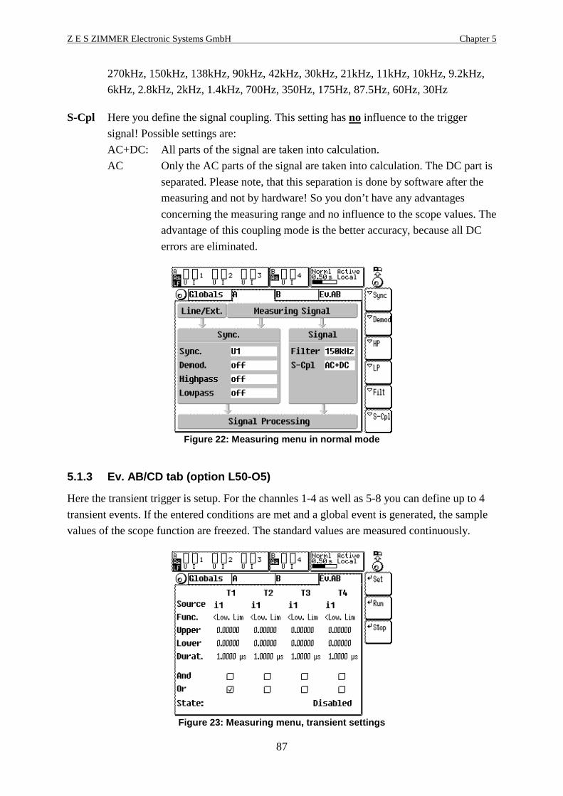
Z E S ZIMMER Electronic Systems GmbH Chapter 5
87
270kHz, 150kHz, 138kHz, 90kHz, 42kHz, 30kHz, 21kHz, 11kHz, 10kHz, 9.2kHz,
6kHz, 2.8kHz, 2kHz, 1.4kHz, 700Hz, 350Hz, 175Hz, 87.5Hz, 60Hz, 30Hz
S-Cpl Here you define the signal coupling. This setting has no influence to the trigger
signal! Possible settings are:
AC+DC: All parts of the signal are taken into calculation.
AC Only the AC parts of the signal are taken into calculation. The DC part is
separated. Please note, that this separation is done by software after the
measuring and not by hardware! So you don’t have any advantages
concerning the measuring range and no influence to the scope values. The
advantage of this coupling mode is the better accuracy, because all DC
errors are eliminated.
Figure 22: Measuring menu in normal mode
5.1.3 Ev. AB/CD tab (option L50-O5)
Here the transient trigger is setup. For the channles 1-4 as well as 5-8 you can define up to 4
transient events. If the entered conditions are met and a global event is generated, the sample
values of the scope function are freezed. The standard values are measured continuously.
Figure 23: Measuring menu, transient settings

Normal measuring mode LMG500
88
Set Is used to change the values. Further on you have to select the transient T1 to T4 (also
called an event channel). Now you have following softkeys available:
Src: This selects the signal which should be observed.
Func This selects, what should be observed at this signal:
<low. limit
>upp. limit
Window Out (<low. limit or >upp. limit)
Window In (>low. limit and <upp. limit)
Up Defines the upper limit. The unit is V, A or W depending on the signal.
Low Defines the lower limit. The unit is V, A or W depending on the signal.
Dur. Defines how long the function has to be met, before this channel notifies an
event.
Cond. This defines, how an event channel is handled:
off: No action
and: A global event is generated, if all event channels with ‘and’ condition
have an event
or: A global event is generated if this event channel is true.
Run Starts the search for a new transient. The search can only be performed, if all measuring
channels of all groups are set to manual!
Stop Stopps the search
5.2 Measuring ranges (Range)
When you came to this menu by pressing Range you can setup all the ranges and scalings for
the different measuring channels. You see three tabs (‘Group A’, ‘Group B’, ... and
‘Sense/More’).

Z E S ZIMMER Electronic Systems GmbH Chapter 5
89
Figure 24: Range menu
5.2.1 Group A/B tab
The settings in group A and B are identical, so they are just described once.
With the keys F1(<-) and F3(->) beside the rotary knob, you can select another U/I channel.
With the rotary knob itself, you can select another range within the selected channel.
A/M With A/M the automatic or manual range setting is selected. This is only possible
in the normal measuring mode. In all other modes the manual range is selected.
Sel.Input By this you can select the jack which should be used as input jack for this channel.
Scale The Scale button allows you to enter a scaling factor. With this scaling factor all
values of this channel (and the power) are multiplied. This setting is usually used
to enter the transformer ratio of current clamps or voltage transformers.
Example 1:
You have a current clamp with 1000A/1A ratio. In this case enter 1000 as scaling
factor.
Example 2:
You have a current clamp with 1A/10mV ratio. This is equal to 100A/V, so you
have to enter 100 as scaling.
Adapt By this you force all channels of this group to work with the same settings like the
actual one. If the actual one works in automatic mode all other work also in
automatic mode. In manual mode all channels get the same range.
Please note, that the scaling is not adapted! The reason is, that sometimes the
scaling factor is used to adjust an external sensor. If the scaling would also be
adapted, the adjustment would be lost.
By pressing the rotary knob again you leave the set mode and can select another tab.
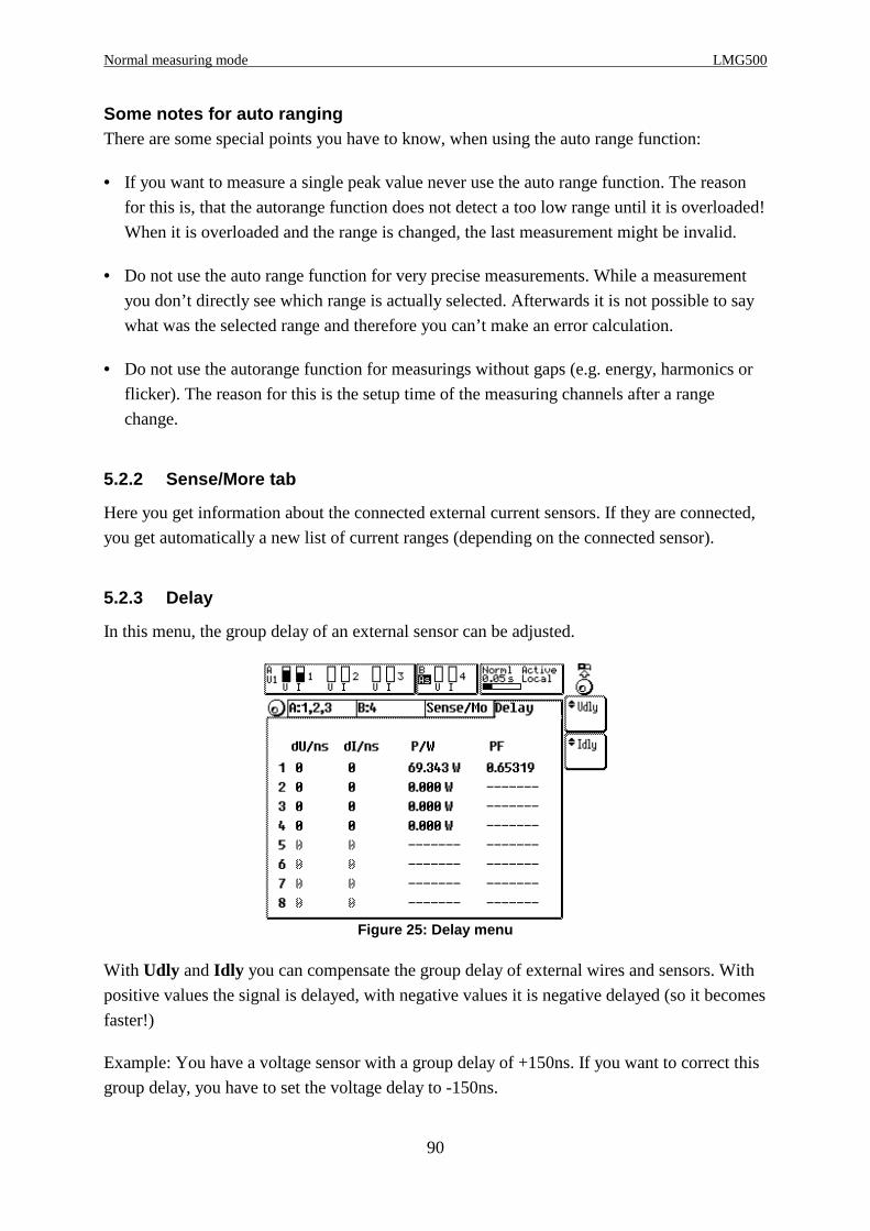
Normal measuring mode LMG500
90
Some notes for auto rangingThere are some special points you have to know, when using the auto range function:
• If you want to measure a single peak value never use the auto range function. The reason
for this is, that the autorange function does not detect a too low range until it is overloaded!
When it is overloaded and the range is changed, the last measurement might be invalid.
• Do not use the auto range function for very precise measurements. While a measurement
you don’t directly see which range is actually selected. Afterwards it is not possible to say
what was the selected range and therefore you can’t make an error calculation.
• Do not use the autorange function for measurings without gaps (e.g. energy, harmonics or
flicker). The reason for this is the setup time of the measuring channels after a range
change.
5.2.2 Sense/More tab
Here you get information about the connected external current sensors. If they are connected,
you get automatically a new list of current ranges (depending on the connected sensor).
5.2.3 Delay
In this menu, the group delay of an external sensor can be adjusted.
Figure 25: Delay menu
With Udly and Idly you can compensate the group delay of external wires and sensors. With
positive values the signal is delayed, with negative values it is negative delayed (so it becomes
faster!)
Example: You have a voltage sensor with a group delay of +150ns. If you want to correct this
group delay, you have to set the voltage delay to -150ns.

Z E S ZIMMER Electronic Systems GmbH Chapter 5
91
While changeing the U-delay or I-delay you can see the actual measured power and power
factor. This can help to estimate the group delay of an external system, if this is unknown
from other sources.
5.3 Definition of measuring values
Following you find the definitions for all measuring values in the normal operation mode. The
values are divided in two sections:
• The values from single measuring are measured while one measuring cycle and are
independent from all other measuring cycles.
• The integrated values are calculated over several cycles.
The following basic definitions are used:
u(t) The instantaneous value if the voltage used for calculation
i(t) The instantaneous value if the current used for calculation
T The time of an integer number of the periods of the synchronisation signal. The integer
factor depends on the chosen measuring cycle time. This time can vary from cycle to
cycle! T is the real measuring time.
The values u(t) and i(t) used for calculation can be the directly in channel n measured values
un(t)/in(t) or calculated from them (depending on the wiring and the selected display channel):
Wiring ‘1+0 Channels’ (1 channel instruments only)
Display channel u(t) i(t)
1 u1(t) i1(t)
Wiring ‘2+0 Channels’ (2 channel instruments only)
Display channel u(t) i(t)
1 u1(t) i1(t)
2 u2(t) i2(t)
9 -u1(t)+u2(t) -i1(t)-i2(t)
Wiring ‘1+1 Channels’ (2 channel instruments only)
Display channel u(t) i(t)
1 u1(t) i1(t)
2 u2(t) i2(t)

Normal measuring mode LMG500
92
Wiring ‘3+0 Channels’ (3 channel instruments only)
Display channel u(t) i(t)
1 u1(t) i1(t)
2 u2(t) i2(t)
3 u3(t) i3(t)
Wiring ‘2+1 Channels’ (3 channel instruments only)
Display channel u(t) i(t)
1 u1(t) i1(t)
2 u2(t) i2(t)
3 u3(t) i3(t)
9 -u1(t)+u2(t) -i1(t)-i2(t)
Wiring ‘4+0 Channels’ (4 channel instruments only)
Display channel u(t) i(t)
1 u1(t) i1(t)
2 u2(t) i2(t)
3 u3(t) i3(t)
4 u4(t) i4(t)
Wiring ‘3+1 Channels’ (4 channel instruments only)
Display channel u(t) i(t)
1 u1(t) i1(t)
2 u2(t) i2(t)
3 u3(t) i3(t)
4 u4(t) i4(t)
Wiring ‘2+2 Channels’ (4 channel instruments only)
Display channel u(t) i(t)
1 u1(t) i1(t)
2 u2(t) i2(t)
3 u3(t) i3(t)
4 u4(t) i4(t)
9 -u1(t)+u2(t) -i1(t)-i2(t)
10 -u3(t)+u4(t) -i3(t)-i4(t)
For further information about the tables see also chapter 2.4, ‘The group concept’.

Z E S ZIMMER Electronic Systems GmbH Chapter 5
93
Linked valuesIf you have installed the option L50-O6 (star to delta conversion) you get the following
additional wirings. The values in the column ‘Measuring channel numbers’ define the internal
calculation of the DSPs (the numbers are the numbers of the measuring channels!!). The
column ‘Circuit number’ defines the physical values of your circuit. This relations are correct,
if you connect your instrument in the correct way. For this refer to the measuring circuit
chapter below each table.
Figure 26: Allocation of the different linked value s
Please not also the hints and restrictions given in 2.5, ‘Linked values, star to delta conversion
(option L50-O6)’
Wiring ‘3+0, U*I*-> U ∆∆∆∆I∆∆∆∆’ (3 channel instruments only)
Measuring channel
numbers
Circuit numbers
Display channel u(t) i(t) U I
1 u1(t) i1(t) U1 I1
2 u2(t) i2(t) U2 I2
3 u3(t) i3(t) U3 I3
9 u1(t)-u2(t) i (t) i (t)
31 2− U12 I12
10 u2(t)-u3(t) i (t) i (t)
32 3− U23 I23
11 u3(t)-u1(t) i (t) i (t)
33 1− U31 I31
For circuit see 3.3.2, ‘Measuring circuit for measuring efficiency of 3/1phase systems’

Normal measuring mode LMG500
94
Wiring ‘3+0, U ∆∆∆∆I*-> U∆∆∆∆I∆∆∆∆’ (3 channel instruments only)
Measuring channel
numbers
Circuit numbers
Display channel u(t) i(t) U I
1 u1(t) i1(t) U12 I1
2 u2(t) i2(t) U23 I2
3 u3(t) i3(t) U31 I3
9 u1(t) i (t) i (t)
31 2− U12 I12
10 u2(t) i (t) i (t)
32 3− U23 I23
11 u3(t) i (t) i (t)
33 1− U31 I31
For circuit see 3.3.3, ‘Measuring circuit (typical) for star to delta conversion (option L50-O6)’
Wiring ‘3+0, U ∆∆∆∆I*-> U*I*’ (3 channel instruments only)
Measuring channel
numbers
Circuit
numbers
Display channel u(t) i(t) U I
1 u1(t) i1(t) U12 I1
2 u2(t) i2(t) U23 I2
3 u3(t) i3(t) U31 I3
9 u (t) u (t)
31 3− i1(t) U1 I1
10 u (t) u (t)
32 1− i2(t) U2 I2
11 u (t) u (t)
33 2− i3(t) U3 I3
For circuit see 3.3.3, ‘Measuring circuit (typical) for star to delta conversion (option L50-O6)’
Wiring ‘3+1, U*I*-> U ∆∆∆∆I∆∆∆∆’ (4 channel instruments only)
Measuring channel
numbers
Circuit numbers
Display channel u(t) i(t) U I
1 u1(t) i1(t) U1 I1
2 u2(t) i2(t) U2 I2
3 u3(t) i3(t) U3 I3
4 u4(t) i4(t) U4 I4
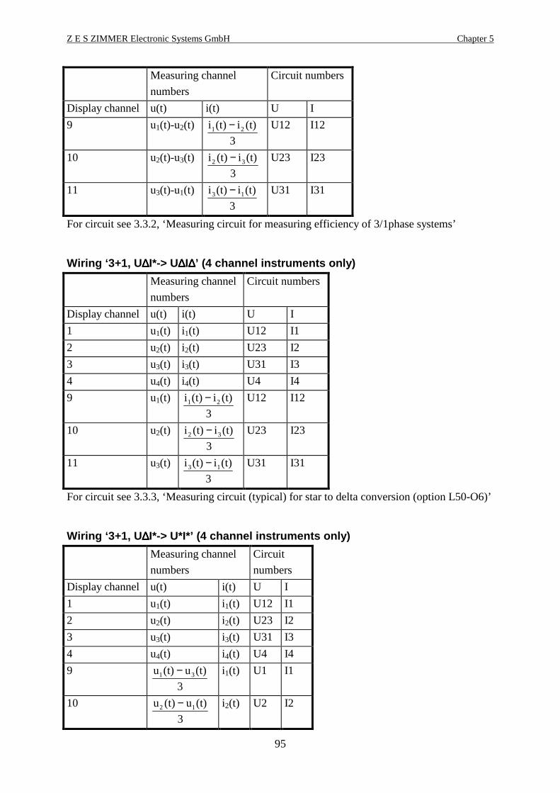
Z E S ZIMMER Electronic Systems GmbH Chapter 5
95
Measuring channel
numbers
Circuit numbers
Display channel u(t) i(t) U I
9 u1(t)-u2(t) i (t) i (t)
31 2− U12 I12
10 u2(t)-u3(t) i (t) i (t)
32 3− U23 I23
11 u3(t)-u1(t) i (t) i (t)
33 1− U31 I31
For circuit see 3.3.2, ‘Measuring circuit for measuring efficiency of 3/1phase systems’
Wiring ‘3+1, U ∆∆∆∆I*-> U∆∆∆∆I∆∆∆∆’ (4 channel instruments only)
Measuring channel
numbers
Circuit numbers
Display channel u(t) i(t) U I
1 u1(t) i1(t) U12 I1
2 u2(t) i2(t) U23 I2
3 u3(t) i3(t) U31 I3
4 u4(t) i4(t) U4 I4
9 u1(t) i (t) i (t)
31 2− U12 I12
10 u2(t) i (t) i (t)
32 3− U23 I23
11 u3(t) i (t) i (t)
33 1− U31 I31
For circuit see 3.3.3, ‘Measuring circuit (typical) for star to delta conversion (option L50-O6)’
Wiring ‘3+1, U ∆∆∆∆I*-> U*I*’ (4 channel instruments only)
Measuring channel
numbers
Circuit
numbers
Display channel u(t) i(t) U I
1 u1(t) i1(t) U12 I1
2 u2(t) i2(t) U23 I2
3 u3(t) i3(t) U31 I3
4 u4(t) i4(t) U4 I4
9 u (t) u (t)
31 3− i1(t) U1 I1
10 u (t) u (t)
32 1− i2(t) U2 I2
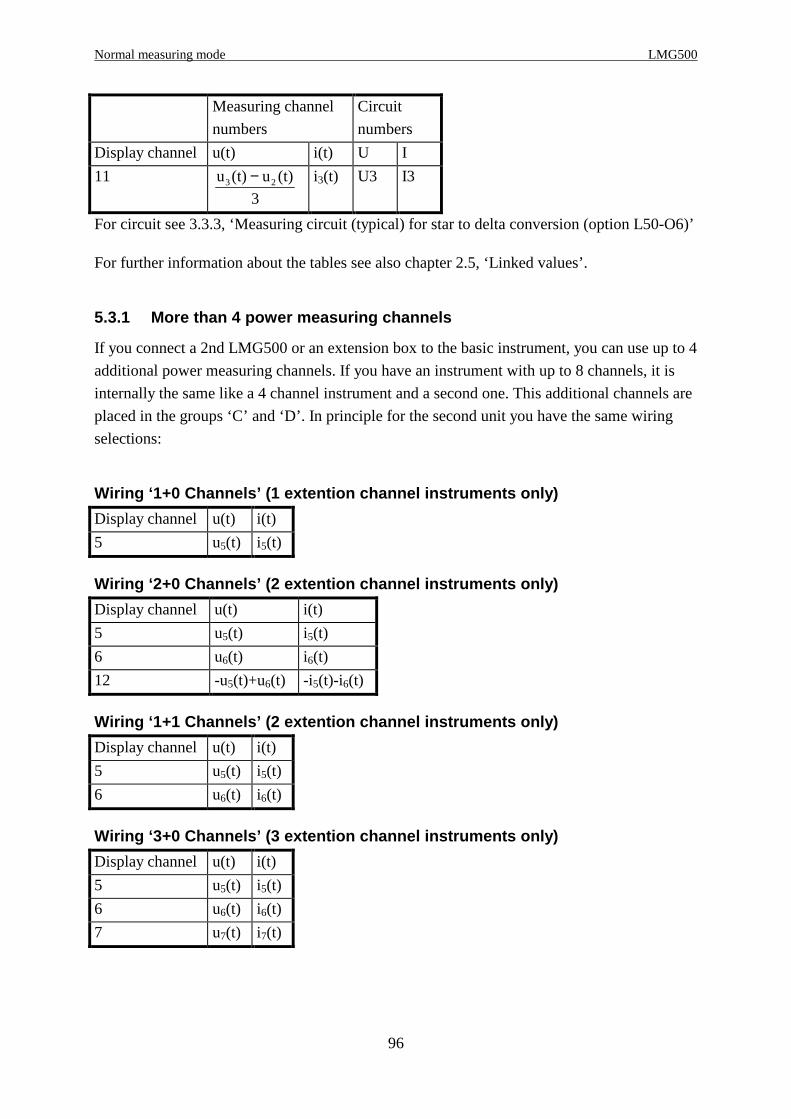
Normal measuring mode LMG500
96
Measuring channel
numbers
Circuit
numbers
Display channel u(t) i(t) U I
11 u (t) u (t)
33 2− i3(t) U3 I3
For circuit see 3.3.3, ‘Measuring circuit (typical) for star to delta conversion (option L50-O6)’
For further information about the tables see also chapter 2.5, ‘Linked values’.
5.3.1 More than 4 power measuring channels
If you connect a 2nd LMG500 or an extension box to the basic instrument, you can use up to 4
additional power measuring channels. If you have an instrument with up to 8 channels, it is
internally the same like a 4 channel instrument and a second one. This additional channels are
placed in the groups ‘C’ and ‘D’. In principle for the second unit you have the same wiring
selections:
Wiring ‘1+0 Channels’ (1 extention channel instrume nts only)
Display channel u(t) i(t)
5 u5(t) i5(t)
Wiring ‘2+0 Channels’ (2 extention channel instrume nts only)
Display channel u(t) i(t)
5 u5(t) i5(t)
6 u6(t) i6(t)
12 -u5(t)+u6(t) -i5(t)-i6(t)
Wiring ‘1+1 Channels’ (2 extention channel instrume nts only)
Display channel u(t) i(t)
5 u5(t) i5(t)
6 u6(t) i6(t)
Wiring ‘3+0 Channels’ (3 extention channel instrume nts only)
Display channel u(t) i(t)
5 u5(t) i5(t)
6 u6(t) i6(t)
7 u7(t) i7(t)
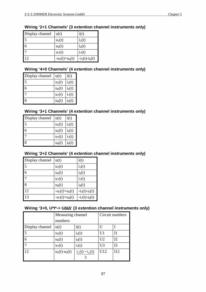
Z E S ZIMMER Electronic Systems GmbH Chapter 5
97
Wiring ‘2+1 Channels’ (3 extention channel instrume nts only)
Display channel u(t) i(t)
5 u5(t) i5(t)
6 u6(t) i6(t)
7 u7(t) i7(t)
12 -u5(t)+u6(t) -i5(t)-i6(t)
Wiring ‘4+0 Channels’ (4 extention channel instrume nts only)
Display channel u(t) i(t)
5 u5(t) i5(t)
6 u6(t) i6(t)
7 u7(t) i7(t)
8 u8(t) i8(t)
Wiring ‘3+1 Channels’ (4 extention channel instrume nts only)
Display channel u(t) i(t)
5 u5(t) i5(t)
6 u6(t) i6(t)
7 u7(t) i7(t)
8 u8(t) i8(t)
Wiring ‘2+2 Channels’ (4 extention channel instrume nts only)
Display channel u(t) i(t)
5 u5(t) i5(t)
6 u6(t) i6(t)
7 u7(t) i7(t)
8 u8(t) i8(t)
12 -u5(t)+u6(t) -i5(t)-i6(t)
13 -u7(t)+u8(t) -i7(t)-i8(t)
Wiring ‘3+0, U*I*-> U ∆∆∆∆I∆∆∆∆’ (3 extention channel instruments only)
Measuring channel
numbers
Circuit numbers
Display channel u(t) i(t) U I
5 u5(t) i5(t) U1 I1
6 u6(t) i6(t) U2 I2
7 u7(t) i7(t) U3 I3
12 u5(t)-u6(t)
3
(t)i(t)i 65 − U12 I12

Normal measuring mode LMG500
98
Measuring channel
numbers
Circuit numbers
Display channel u(t) i(t) U I
13 u6(t)-u7(t)
3
(t)i(t)i 76 − U23 I23
14 u7(t)-u5(t)
3
(t)i(t)i 57 − U31 I31
Wiring ‘3+0, U ∆∆∆∆I*-> U∆∆∆∆I∆∆∆∆’ (3 extention channel instruments only)
Measuring channel
numbers
Circuit numbers
Display channel u(t) i(t) U I
5 u5(t) i5(t) U12 I1
6 u6(t) i6(t) U23 I2
7 u7(t) i7(t) U31 I3
12 u5(t)
3
(t)i(t)i 65 − U12 I12
13 u6(t)
3
(t)i(t)i 76 − U23 I23
14 u7(t)
3
(t)i(t)i 57 − U31 I31
Wiring ‘3+0, U ∆∆∆∆I*-> U*I*’ (3 extention channel instruments only)
Measuring channel
numbers
Circuit
numbers
Display channel u(t) i(t) U I
5 u5(t) i5(t) U12 I1
6 u6(t) i6(t) U23 I2
7 u7(t) i7(t) U31 I3
12
3
(t)u(t)u 75 − i5(t) U1 I1
13
3
(t)u(t)u 56 − i6(t) U2 I2
14
3
(t)u(t)u 67 − i7(t) U3 I3

Z E S ZIMMER Electronic Systems GmbH Chapter 5
99
Wiring ‘3+1, U*I*-> U ∆∆∆∆I∆∆∆∆’ (4 extention channel instruments only)
Measuring channel
numbers
Circuit numbers
Display channel u(t) i(t) U I
5 u5(t) i5(t) U1 I1
6 u6(t) i6(t) U2 I2
7 u7(t) i7(t) U3 I3
8 u8(t) i8(t) U4 I4
12 u5(t)-u6(t)
3
(t)i(t)i 65 − U12 I12
13 u6(t)-u7(t)
3
(t)i(t)i 76 − U23 I23
14 u7(t)-u5(t)
3
(t)i(t)i 57 − U31 I31
Wiring ‘3+1, U ∆∆∆∆I*-> U∆∆∆∆I∆∆∆∆’ (4 extention channel instruments only)
Measuring channel
numbers
Circuit numbers
Display channel u(t) i(t) U I
5 u5(t) i5(t) U12 I1
6 u6(t) i6(t) U23 I2
7 u7(t) i7(t) U31 I3
8 u8(t) i8(t) U4 I4
12 u5(t)
3
(t)i(t)i 65 − U12 I12
13 u6(t)
3
(t)i(t)i 76 − U23 I23
14 u7(t)
3
(t)i(t)i 57 − U31 I31
Wiring ‘3+1, U ∆∆∆∆I*-> U*I*’ (4 extention channel instruments only)
Measuring channel
numbers
Circuit
numbers
Display channel u(t) i(t) U I
5 u5(t) i5(t) U12 I1
6 u6(t) i6(t) U23 I2
7 u7(t) i7(t) U31 I3
8 u8(t) i8(t) U4 I4
12
3
(t)u(t)u 75 − i5(t) U1 I1

Normal measuring mode LMG500
100
Measuring channel
numbers
Circuit
numbers
Display channel u(t) i(t) U I
13
3
(t)u(t)u 56 − i6(t) U2 I2
14
3
(t)u(t)u 67 − i7(t) U3 I3
5.3.2 Values from single measuring
Voltage and current
true root mean square:UtrmsT
u t dtt
T=
=∫
1 2
0( ) Itrms
Ti t dt
t
T=
=∫
1 2
0( )
DCn negative DC component:
UdcnT
u t for u t
for u tdt
t
T=
<
≥
=
∫1 0
0 00
( ) ( )
( )Idcn
T
i t for i t
for i tdt
t
T=
<
≥
=
∫1 0
0 00
( ) ( )
( )
DCp positive DC component:
∫ =
<≥
=T
tdt
tufor
tufortu
TUdcp
0 0)(0
0)()(1∫ =
<≥
=T
tdt
tifor
tiforti
TIdcp
0 0)(0
0)()(1
DC component: UdcT
u t dtt
T=
=∫
1
0( ) Idc
Ti t dt
t
T=
=∫
1
0( )
AC component: Uac Utrms Udc= −2 2 Iac Itrms Idc= −2 2
peak-peak value: Upp u t u t= −max( ( )) min( ( )) Ipp i t i t= −max( ( )) min( ( ))
rectified value: UrectT
u t dtt
T=
=∫
1
0( ) Irect
Ti t dt
t
T=
=∫
1
0( )
crest factor: UcfUpk
Utrms= Icf
Ipk
Itrms=
form factor: UffUtrms
Urect= Iff
Itrms
Irect=
Inrush current: Iinr i t= max( ( ) )
Power
active power: PT
u t i t dtt
T=
=∫
1
0( ) ( )
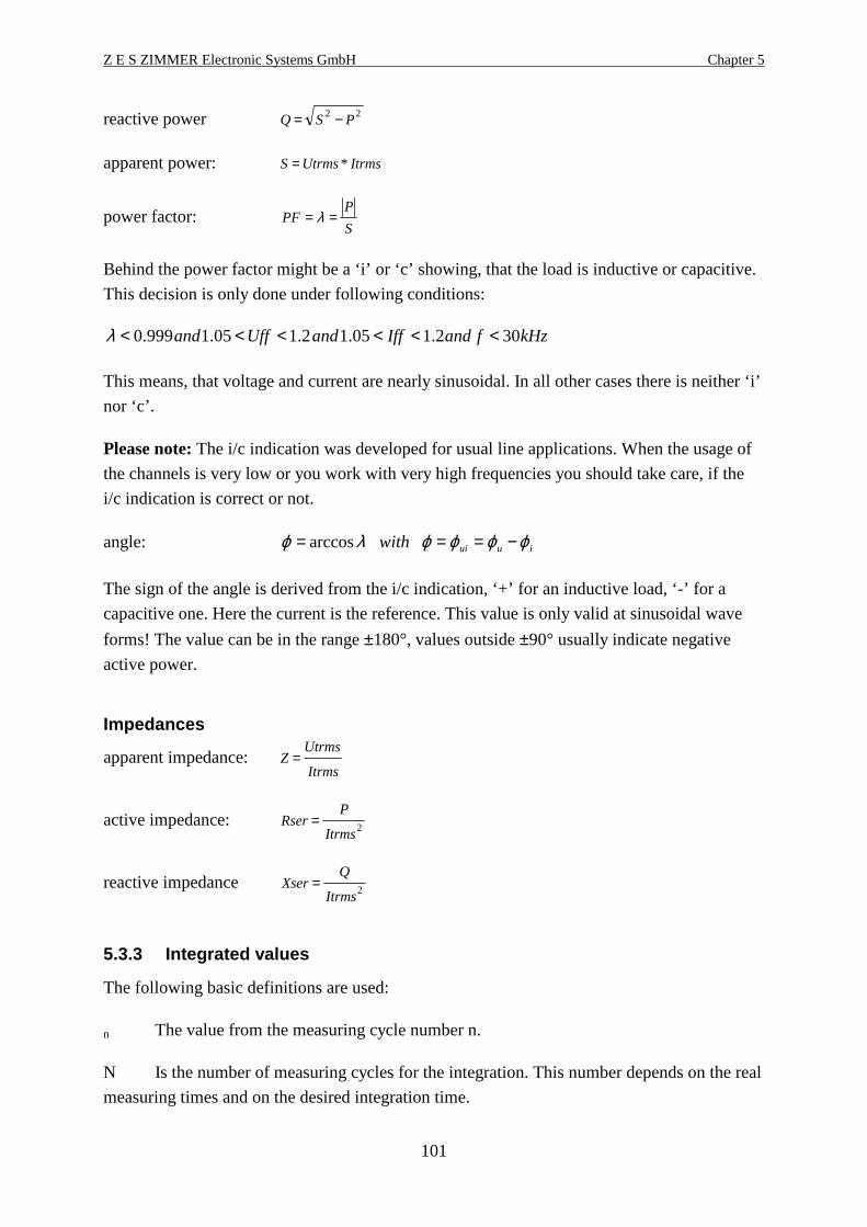
Z E S ZIMMER Electronic Systems GmbH Chapter 5
101
reactive power Q S P= −2 2
apparent power: S Utrms Itrms= *
power factor:S
PPF == λ
Behind the power factor might be a ‘i’ or ‘c’ showing, that the load is inductive or capacitive.
This decision is only done under following conditions:
kHzfandIffandUffand 302.105.12.105.1999.0 <<<<<<λ
This means, that voltage and current are nearly sinusoidal. In all other cases there is neither ‘i’
nor ‘c’.
Please note: The i/c indication was developed for usual line applications. When the usage of
the channels is very low or you work with very high frequencies you should take care, if the
i/c indication is correct or not.
angle: iuuiwith ϕϕϕϕλϕ −=== arccos
The sign of the angle is derived from the i/c indication, ‘+’ for an inductive load, ‘-’ for a
capacitive one. Here the current is the reference. This value is only valid at sinusoidal wave
forms! The value can be in the range ±180°, values outside ±90° usually indicate negative
active power.
Impedances
apparent impedance: ZUtrms
Itrms=
active impedance: RserP
Itrms= 2
reactive impedance XserQ
Itrms= 2
5.3.3 Integrated values
The following basic definitions are used:
n The value from the measuring cycle number n.
N Is the number of measuring cycles for the integration. This number depends on the real
measuring times and on the desired integration time.

Normal measuring mode LMG500
102
Energy
active energy: EP P Tn nn
N=
=∑ *0
reactive energy: EQ Q Tn nn
N=
=∑ *0
apparent energy ES S Tn nn
N=
=∑ *0
Average values
average active power: PmEP
Tnn
N=
=∑0
average reactive power:QmEQ
Tnn
N==∑
0
average apparent powerSmES
Tnn
N==∑
0
Miscellaneous
charge: q Idc Tn nn
N=
=∑ *0
integration time: t Tnn
N=
=∑0
5.3.4 Total values
This are values which are calculated over several channels of one group. Following symbols
are used:
f first channel of the group
l last channel of the group
s number of the display channel for the total values
These three symbols depend on the wiring. Please refer to 2.4, ‘The group concept’ and 2.5,
‘Linked values’ for details
Following values are calculated for the total values display channels (all other values are
invalid):
collective sum voltage:U Us n f
l
TRMS nTRMS=
=∑ 2
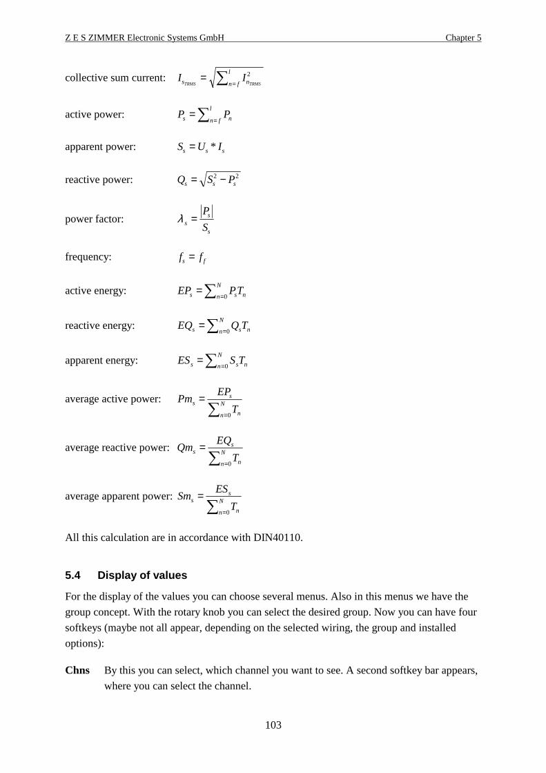
Z E S ZIMMER Electronic Systems GmbH Chapter 5
103
collective sum current: I Is nn f
l
TRMS TRMS=
=∑ 2
active power: P Ps nn f
l==∑
apparent power: S U Is s s= *
reactive power: Q S Ps s s= −2 2
power factor: λ ss
s
P
S=
frequency: f fs f=
active energy: ∑ == N
n nss TPEP0
reactive energy: ∑ == N
n nss TQEQ0
apparent energy: ∑ == N
n nss TSES0
average active power:∑ =
= N
n n
ss
T
EPPm
0
average reactive power:∑ =
= N
n n
ss
T
EQQm
0
average apparent power:∑ =
= N
n n
ss
T
ESSm
0
All this calculation are in accordance with DIN40110.
5.4 Display of values
For the display of the values you can choose several menus. Also in this menus we have the
group concept. With the rotary knob you can select the desired group. Now you can have four
softkeys (maybe not all appear, depending on the selected wiring, the group and installed
options):
Chns By this you can select, which channel you want to see. A second softkey bar appears,
where you can select the channel.
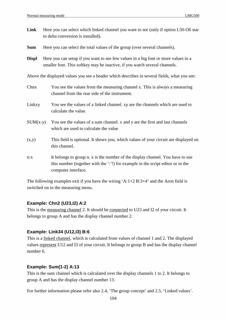
Normal measuring mode LMG500
104
Link Here you can select which linked channel you want to see (only if option L50-O6 star
to delta conversion is installed).
Sum Here you can select the total values of the group (over several channels).
Displ Here you can setup if you want to see few values in a big font or more values in a
smaller font. This softkey may be inactive, if you watch several channels.
Above the displayed values you see a header which describes in several fields, what you see:
Chnx You see the values from the measuring channel x. This is always a measuring
channel from the rear side of the instrument.
Linkxy You see the values of a linked channel. xy are the channels which are used to
calculate the value.
SUM(x-y) You see the values of a sum channel. x and y are the first and last channels
which are used to calculate the value
(x,y) This field is optional. It shows you, which values of your circuit are displayed on
this channel.
n:x It belongs to group n. x is the number of the display channel. You have to use
this number (together with the ‘:’!) for example in the script editor or in the
computer interface.
The following examples exit if you have the wiring ‘A:1+2 B:3+4’ and the Aron field is
switched on in the measuring menu.
Example: Chn2 (U23,I2) A:2This is the measuring channel 2. It should be connected to U23 and I2 of your circuit. It
belongs to group A and has the display channel number 2.
Example: Link34 (U12,I3) B:6This is a linked channel, which is calculated from values of channel 1 and 2. The displayed
values represent U12 and I3 of your circuit. It belongs to group B and has the display channel
number 6.
Example: Sum(1-2) A:13This is the sum channel which is calculated over the display channels 1 to 2. It belongs to
group A and has the display channel number 13.
For further information please refer also 2.4, ‘The group concept’ and 2.5, ‘Linked values’.

Z E S ZIMMER Electronic Systems GmbH Chapter 5
105
5.4.1 Default
With Default you see the most important values of the instrument. For the handling please see
the general description in chapter 5.4, ‘Display of values’.
Figure 27: Default display with one and four channe ls
5.4.2 Voltage
With Voltage you see the most important voltage values of the instrument. For the handling
please see the general description in chapter 5.4, ‘Display of values’.
5.4.3 Current
With Current you see the most important current values of the instrument. For the handling
please see the general description in chapter 5.4, ‘Display of values’. With the Inrsh key you
can reset the last measured inrush current to 0. This softkey is only available when the manual
measuring range is selected for the current and the voltage! The average in the measuring
menu has to be set to 1! If the inrush current is too big for the measuring range, a dashed line
is displayed.
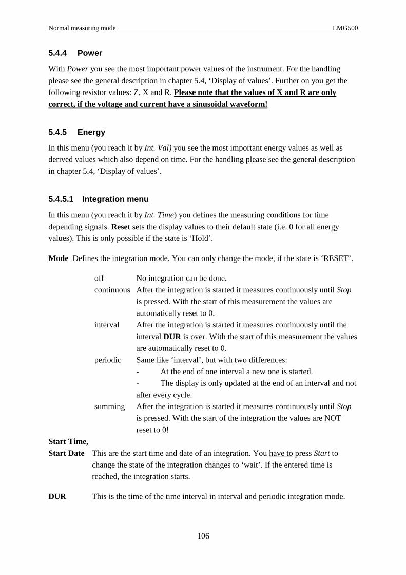
Normal measuring mode LMG500
106
5.4.4 Power
With Power you see the most important power values of the instrument. For the handling
please see the general description in chapter 5.4, ‘Display of values’. Further on you get the
following resistor values: Z, X and R. Please note that the values of X and R are onlycorrect, if the voltage and current have a sinusoidal waveform!
5.4.5 Energy
In this menu (you reach it by Int. Val) you see the most important energy values as well as
derived values which also depend on time. For the handling please see the general description
in chapter 5.4, ‘Display of values’.
5.4.5.1 Integration menu
In this menu (you reach it by Int. Time) you defines the measuring conditions for time
depending signals. Reset sets the display values to their default state (i.e. 0 for all energy
values). This is only possible if the state is ‘Hold’.
Mode Defines the integration mode. You can only change the mode, if the state is ‘RESET’.
off No integration can be done.
continuous After the integration is started it measures continuously until Stop
is pressed. With the start of this measurement the values are
automatically reset to 0.
interval After the integration is started it measures continuously until the
interval DUR is over. With the start of this measurement the values
are automatically reset to 0.
periodic Same like ‘interval’, but with two differences:
- At the end of one interval a new one is started.
- The display is only updated at the end of an interval and not
after every cycle.
summing After the integration is started it measures continuously until Stop
is pressed. With the start of the integration the values are NOT
reset to 0!
Start Time,Start Date This are the start time and date of an integration. You have to press Start to
change the state of the integration changes to ‘wait’. If the entered time is
reached, the integration starts.
DUR This is the time of the time interval in interval and periodic integration mode.

Z E S ZIMMER Electronic Systems GmbH Chapter 5
107
Runtime is the running integration time. Please note, that this time can be smaller than the real
time, for example because of invalid measuring cycles while a change in the measuring
ranges.
Start of integrationIn general there are three ways to start an integration. You can either enter a start time with
Start Time, Start Date, or you can simply press the Start button or you can start via the
external sync jack of the LMG. The first cycle which is taken into account is the cycle which
follows the actual cycle.
The integration time should be an integer number of times the cycle time.
Stop of integrationThe last cycle which is taken into account is the cycle when the Stop button or any other stop
signal appear.
State of integrationThe integration can be in 6 different states:
Reset The energy measurement is stopped, the values are reset to 0
Wait If the start time is later than the actual time and you have started the integration this
state appears until the start time is reached.
Start This state is displayed from the logical start of integration (e.g. pressing the Start
button) until the physical start of integration which is always the begin of the next
cycle.
Run This is displayed while the physical integration is running
Stop This state is displayed from the logical end of integration (e.g. pressing the Stop
button) until the physical end of integration which is always the end of the actual
cycle.
Hold This is displayed if the integration has finished. The integrated values are hold, until
the integration continuous (only summing mode) or the values are reset by RESETor Start.
The logical integration is running, if the state is displayed inverse.
5.4.6 Graphical display
With Graph you see the graphical display of the normal measuring mode. Also in this menu
we have the group concept. With the rotary knob you can select different tabs (‘Scope A’,
‘Scope B’, ‘Vec.A’ and ‘Vec.B’).
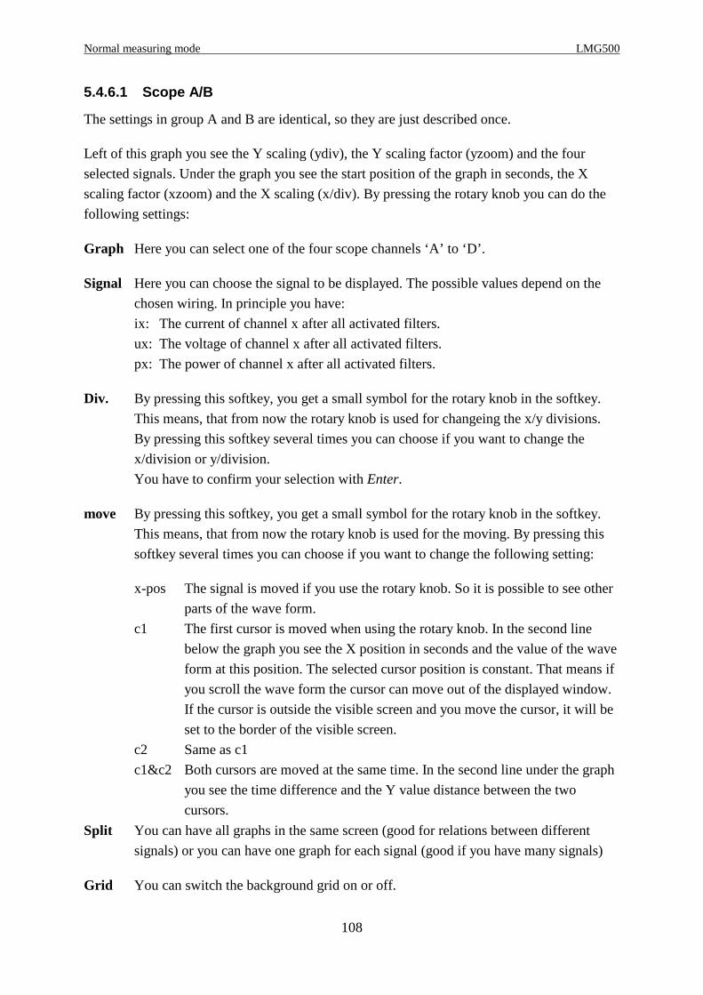
Normal measuring mode LMG500
108
5.4.6.1 Scope A/B
The settings in group A and B are identical, so they are just described once.
Left of this graph you see the Y scaling (ydiv), the Y scaling factor (yzoom) and the four
selected signals. Under the graph you see the start position of the graph in seconds, the X
scaling factor (xzoom) and the X scaling (x/div). By pressing the rotary knob you can do the
following settings:
Graph Here you can select one of the four scope channels ‘A’ to ‘D’.
Signal Here you can choose the signal to be displayed. The possible values depend on the
chosen wiring. In principle you have:
ix: The current of channel x after all activated filters.
ux: The voltage of channel x after all activated filters.
px: The power of channel x after all activated filters.
Div. By pressing this softkey, you get a small symbol for the rotary knob in the softkey.
This means, that from now the rotary knob is used for changeing the x/y divisions.
By pressing this softkey several times you can choose if you want to change the
x/division or y/division.
You have to confirm your selection with Enter.
move By pressing this softkey, you get a small symbol for the rotary knob in the softkey.
This means, that from now the rotary knob is used for the moving. By pressing this
softkey several times you can choose if you want to change the following setting:
x-pos The signal is moved if you use the rotary knob. So it is possible to see other
parts of the wave form.
c1 The first cursor is moved when using the rotary knob. In the second line
below the graph you see the X position in seconds and the value of the wave
form at this position. The selected cursor position is constant. That means if
you scroll the wave form the cursor can move out of the displayed window.
If the cursor is outside the visible screen and you move the cursor, it will be
set to the border of the visible screen.
c2 Same as c1
c1&c2 Both cursors are moved at the same time. In the second line under the graph
you see the time difference and the Y value distance between the two
cursors.
Split You can have all graphs in the same screen (good for relations between different
signals) or you can have one graph for each signal (good if you have many signals)
Grid You can switch the background grid on or off.

Z E S ZIMMER Electronic Systems GmbH Chapter 5
109
Figure 28: Scope display with split off/on
5.4.6.2 Plot function
Figure 29: The plot display; split off
In this menu all measured values can be displayed over the time in one or four plots. On the
left side, the information segment, the following settings are displayed:
The plotted signal is shown in the colour in which the graph is drawn.
dy scaling of the y axis per division

Normal measuring mode LMG500
110
y0 offset of the y axis (value of the centre line)
c value of the function at the cursor position
Below the graphs the time depending values are displayed:
dt scaling of the x axis per division
c1 x value of the first cursor
c2 x values of the second cursor
cdt time difference between the cursors
The following settings can be done with the softkeys on the right side:
Chn changes the displayed channel (A-D)
Signl Pressing this softkey a list will open, in which you can adjust the following parameters
(refer chapter 4.5):
Signl here you can select the signal to be plot
y/div here you can select the scaling factor of the Y axis
y0 here you can select the offset of the y axis (value of the centre line).
Example: If you select y0 = 200V and y/div = 10V the you will see a
window from 180V to 220V on the screen.
Auto Scale If you check this box, the signal will be fitted, if it is outside the display
range.
Each setting is confirmed with Enter and rejected with Esc.
y- pressing this softkey - the rotary knob symbol appears in the upper left corner - the
adjustments of the y axis can be changed while the plot is running. Each pressing of
the button toggles between the parameters dy and y0. The adjusted values can be
changed with the rotary knob. The adjustments will be confirmed by pressing the
rotary knob or with the Enter key.
Move here the cursors are selected. With the rotary knob the cursors will scroll through the
plot. For easy reading of the values the plot should be frozen. The scrolling of the
cursors can be done for each cursor separately or for both together.
c1 the first cursor is moved. below the graphs the values for the x position in
seconds and the value of the function are shown.
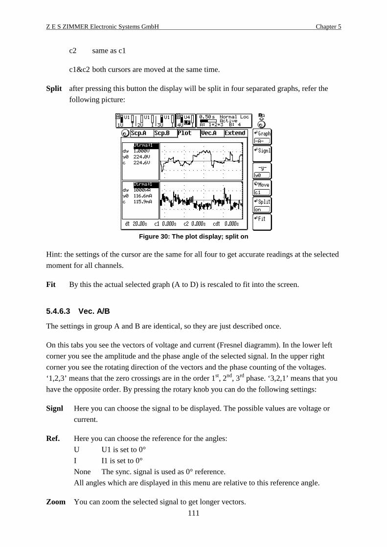
Z E S ZIMMER Electronic Systems GmbH Chapter 5
111
c2 same as c1
c1&c2 both cursors are moved at the same time.
Split after pressing this button the display will be split in four separated graphs, refer the
following picture:
Figure 30: The plot display; split on
Hint: the settings of the cursor are the same for all four to get accurate readings at the selected
moment for all channels.
Fit By this the actual selected graph (A to D) is rescaled to fit into the screen.
5.4.6.3 Vec. A/B
The settings in group A and B are identical, so they are just described once.
On this tabs you see the vectors of voltage and current (Fresnel diagramm). In the lower left
corner you see the amplitude and the phase angle of the selected signal. In the upper right
corner you see the rotating direction of the vectors and the phase counting of the voltages.
‘1,2,3’ means that the zero crossings are in the order 1st, 2nd, 3rd phase. ‘3,2,1’ means that you
have the opposite order. By pressing the rotary knob you can do the following settings:
Signl Here you can choose the signal to be displayed. The possible values are voltage or
current.
Ref. Here you can choose the reference for the angles:
U U1 is set to 0°
I I1 is set to 0°
None The sync. signal is used as 0° reference.
All angles which are displayed in this menu are relative to this reference angle.
Zoom You can zoom the selected signal to get longer vectors.

Normal measuring mode LMG500
112
Figure 31: Vector (Fresnel) diagramm
Please note following1. The angels between the voltages are calculated from the time of the zero crossing in each
phase. If you have big distortions on the voltage, this values might be wrong. You can use
all possible filter to smooth the voltage.
When using the ‘HARM100’ measuring mode, this problems will not occur!
2. The angels of the currents are calculated from the power factor. If voltage and current are
sinusoidal this value is identical to the cosϕ and the calculated angels are correct. If you
have distortions in the voltage or current signal, this values might be wrong! You can use
all possible filters to smooth the voltage and current. Then you can see the phase shift
between the fundamentals.
When using the ‘HARM100’ measuring mode, this problems will not occur!
3. In Aron circuit the calculation of the power factors is in general wrong (this is a
disadvantage of this circuit!). So also the current angles are wrong (see above). But you can
get valid power factors (and angles) if you use the star to delta conversion (option).
For interface access or other usage inside the instrument please refer to following chapters:9.2.4.1.1.9 Phase angle of current9.2.4.1.1.13 Amplitude of current9.2.4.1.14.9 Phase angle of voltage9.2.4.1.14.13 Amplitude of voltage9.2.10.8.3 Reference setting for angles
5.4.7 Custom menu
With Custom you see the custom menu. Here you can setup your own menus, calculate
formulas and execute programs. See 4.4.3, ‘Custom menu’ and 4.4.4, ‘Script/Formula editor’.
5.5 Storage of values
First you have to change to the menu you want to print out or to store and press Print/Log
(exact handling see 10, ‘Logging of values to drives, printer and interfaces’). All the values
you see in this menu are printed out.
Z E S ZIMMER Electronic Systems GmbH Chapter 6
113
6 CE-Harmonic measuring mode (option L50-O9)
In the CE-Harmonic measuring mode the LMG500 works as an high precision harmonic
analyser. The number of settings have been reduced to the needed ones to avoid fail handling.
Note!The synchronisation is fixed to U. For this reason it is important to have a valid signal for
synchronisation to get measuring results. The valid frequency range is from 45 to 65Hz!
6.1 Measuring configuration (Measuring)
The synchronisation is fixed to the voltage channel. With the rotary knob you can select three
tabs (‘Globals’, ‘Group A’ and ‘Group B’).
6.1.1 Global tab
Here the general settings are done.
Eval Selects how the measuring results have to be evaluated:
Class A The signal is judged according class A of EN61000-3-2:1995 or
EN61000-3-2:2006
Class B The signal is judged according class B of EN61000-3-2:1995 or
EN61000-3-2:2006
Class C-1 The signal is judged according class C, Table 1 of EN61000-3-2:1995
or EN61000-3-2:2006
Class C-2 The signal is judged according class C, Table 2 of EN61000-3-2:1995
or EN61000-3-2:2006
Class C-3 The signal is judged according class C, Table 3 of EN61000-3-2:1995
or EN61000-3-2:2006
Class C-W The signal is judged according class C, special waveform according
7.3 b) of EN61000-3-2:2006
Class D The signal is judged according class D of EN61000-3-2:1995 or
EN61000-3-2:2006
Table 2 The signal is judged according table 2 of EN61000-3-12:2005
Table 3 The signal is judged according table 3 of EN61000-3-12:2005
Table 4 The signal is judged according table 4 of EN61000-3-12:2005
EN... This selects the standard which defines the exact measuring mode of the harmonic
analyser:

CE-Harmonic measuring mode (option L50-O9) LMG500
114
2:95/-4-7:93 The combination EN61000-3-2:1995 and EN61000-4-7:1993 is
active
2:95/-4-7:02 The combination EN61000-3-2:1995 and EN61000-4-7:2008 is
active
2:00/-4-7:93 The combination EN61000-3-2:2006 and EN61000-4-7:1993 is
active
2:00/-4-7:02 The combination EN61000-3-2:2006 and EN61000-4-7:2008 is
active
12:05/-4-7:02 The combination EN61000-3-12:2005 and EN61000-4-7:2008 is
active
Systm This selects the system which is used for the measurement. There are four possible
values:
220V/50Hz, 230V/50Hz, 240V/50Hz
220V/60Hz, 230V/60Hz, 240V/60Hz
120V/50Hz
120V/60Hz
The system is required for example for checking the correct frequency of the
measuring setup.
Intv This selects the measuring time for a long time evaluation, for example if you have
devices with fluctuation harmonics. The result you can see in the Int-Value menu.
SmoothHere you can switch the 1.5s low pass filters for smoothing the fluctuating harmonics
on or off. With EN61000-3-2:2006 this point is always on!
Figure 32: Measuring menu in CE-Harm mode
6.1.2 Group A/B tab
The settings in group A and B are identical, so they are just described once.

Z E S ZIMMER Electronic Systems GmbH Chapter 6
115
This tab is only accessible if you have chosen EN61000-3-2:2006 with Class C or D or
EN61000-3-12!
Here you have to setup the setting which are required for EN61000-3-2:2006. For class C you
have to enter the fundamental current and the power factor or your device. For class D you
have to enter the active power.
This values are used to calculate the limits. For each value the average measured one is
compared to the entered one. If there is a difference of more than 10% all the limits are
calculated again with the measured values. In this case it might be, that you have to compare
all the measuring results again against the new limits. For this purpose we recommend to use a
special test and evaluation software (like for the SYS61K system).
Class CWith PF and Curr you can enter the power factor and the fundamental current.
Class DWith Pow you can enter the active power.
EN61000-3-12With Rsce you enter the Rsce value of the system.
6.2 Measuring ranges (Range)
The settings are the same like in 5.2, ‘Measuring ranges (Range)’. Please note that the
standards require a continuous measuring without gaps. For that reason the auto range
function should be deactivated to prevent a range change, because this will cause a short
measurement with invalid values.
6.3 Definition of measuring values
The following basic definitions are used:
n The harmonic order.
T The time of an integer number of the periods of the synchronisation signal
Voltage and current
true root mean square: UtrmsT
u t dtt
T=
=∫
1 2
0( ) Itrms
Ti t dt
t
T=
=∫
1 2
0( )
DC component: UdcT
u t dtt
T=
=∫1
0( ) Idc
Ti t dt
t
T=
=∫
1
0( )
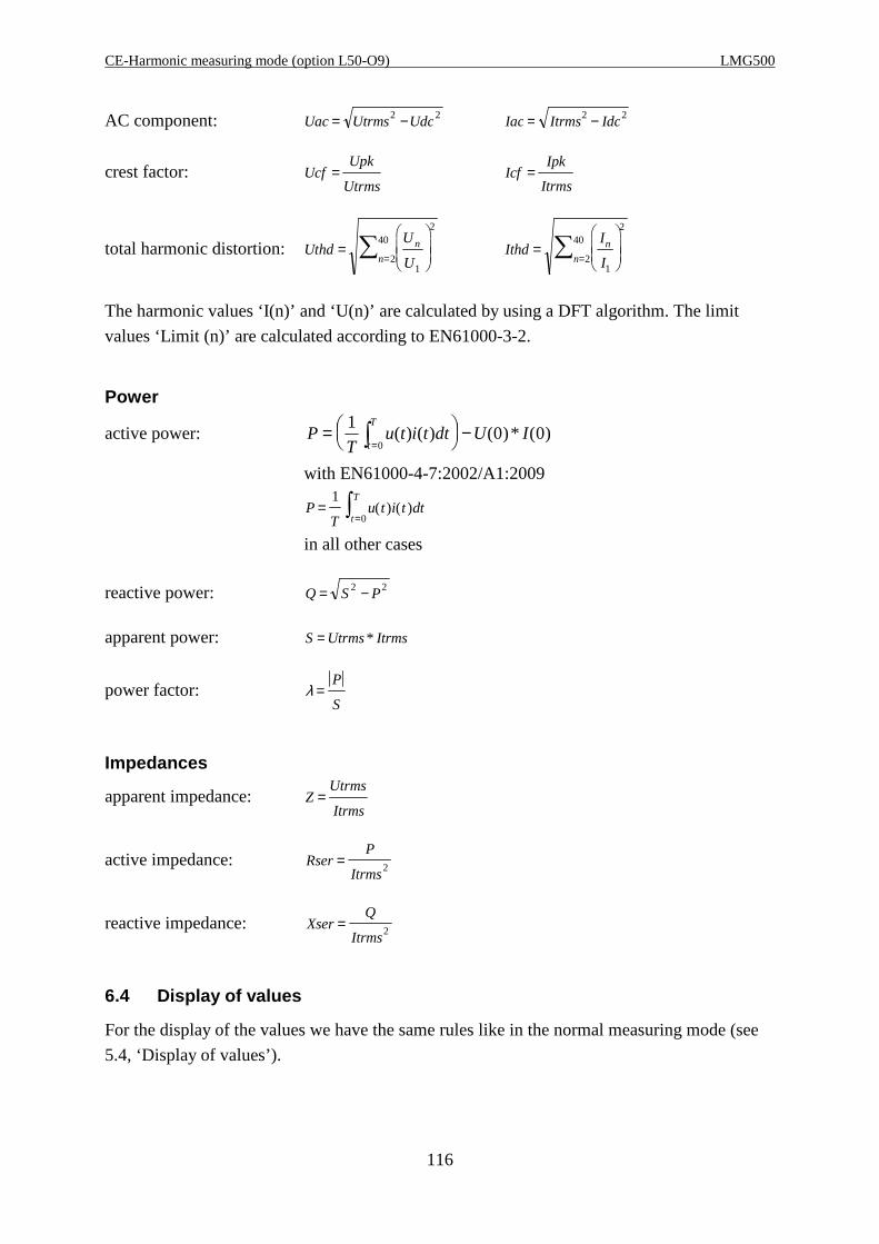
CE-Harmonic measuring mode (option L50-O9) LMG500
116
AC component: Uac Utrms Udc= −2 2 Iac Itrms Idc= −2 2
crest factor: UcfUpk
Utrms= Icf
Ipk
Itrms=
total harmonic distortion: UthdU
U
n
n=
=∑
1
2
2
40Ithd
I
I
n
n=
=∑
1
2
2
40
The harmonic values ‘I(n)’ and ‘U(n)’ are calculated by using a DFT algorithm. The limit
values ‘Limit (n)’ are calculated according to EN61000-3-2.
Power
active power: PT
u t i t dt U It
T=
−
=∫1
0 00
( ) ( ) ( ) * ( )
with EN61000-4-7:2002/A1:2009
PT
u t i t dtt
T=
=∫
1
0( ) ( )
in all other cases
reactive power: Q S P= −2 2
apparent power: S Utrms Itrms= *
power factor: λ =P
S
Impedances
apparent impedance: ZUtrms
Itrms=
active impedance: RserP
Itrms= 2
reactive impedance: XserQ
Itrms= 2
6.4 Display of values
For the display of the values we have the same rules like in the normal measuring mode (see
5.4, ‘Display of values’).
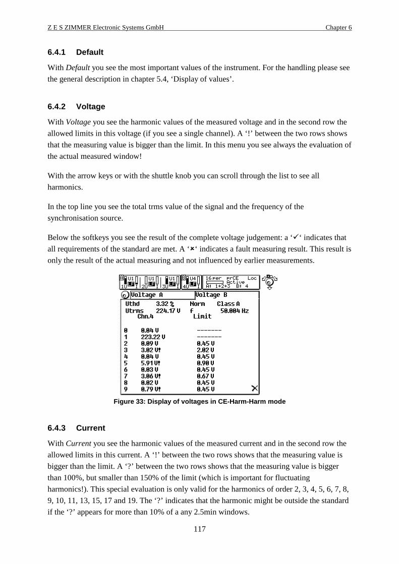
Z E S ZIMMER Electronic Systems GmbH Chapter 6
117
6.4.1 Default
With Default you see the most important values of the instrument. For the handling please see
the general description in chapter 5.4, ‘Display of values’.
6.4.2 Voltage
With Voltage you see the harmonic values of the measured voltage and in the second row the
allowed limits in this voltage (if you see a single channel). A ‘!’ between the two rows shows
that the measuring value is bigger than the limit. In this menu you see always the evaluation of
the actual measured window!
With the arrow keys or with the shuttle knob you can scroll through the list to see all
harmonics.
In the top line you see the total trms value of the signal and the frequency of the
synchronisation source.
Below the softkeys you see the result of the complete voltage judgement: a ‘‘ indicates that
all requirements of the standard are met. A ‘‘ indicates a fault measuring result. This result is
only the result of the actual measuring and not influenced by earlier measurements.
Figure 33: Display of voltages in CE-Harm-Harm mode
6.4.3 Current
With Current you see the harmonic values of the measured current and in the second row the
allowed limits in this current. A ‘!’ between the two rows shows that the measuring value is
bigger than the limit. A ‘?’ between the two rows shows that the measuring value is bigger
than 100%, but smaller than 150% of the limit (which is important for fluctuating
harmonics!). This special evaluation is only valid for the harmonics of order 2, 3, 4, 5, 6, 7, 8,
9, 10, 11, 13, 15, 17 and 19. The ‘?’ indicates that the harmonic might be outside the standard
if the ‘?’ appears for more than 10% of a any 2.5min windows.
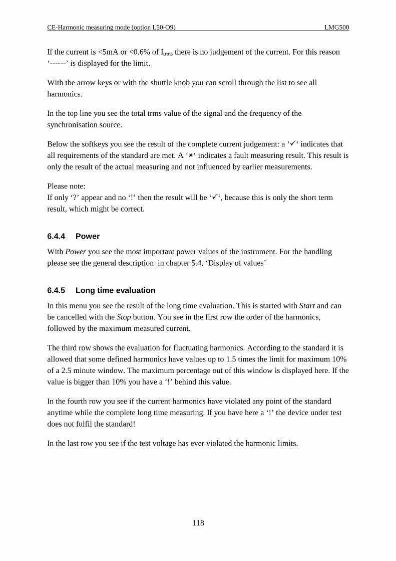
CE-Harmonic measuring mode (option L50-O9) LMG500
118
If the current is <5mA or <0.6% of Itrms there is no judgement of the current. For this reason
‘------’ is displayed for the limit.
With the arrow keys or with the shuttle knob you can scroll through the list to see all
harmonics.
In the top line you see the total trms value of the signal and the frequency of the
synchronisation source.
Below the softkeys you see the result of the complete current judgement: a ‘‘ indicates that
all requirements of the standard are met. A ‘‘ indicates a fault measuring result. This result is
only the result of the actual measuring and not influenced by earlier measurements.
Please note:
If only ‘?’ appear and no ‘!’ then the result will be ‘‘, because this is only the short term
result, which might be correct.
6.4.4 Power
With Power you see the most important power values of the instrument. For the handling
please see the general description in chapter 5.4, ‘Display of values’
6.4.5 Long time evaluation
In this menu you see the result of the long time evaluation. This is started with Start and can
be cancelled with the Stop button. You see in the first row the order of the harmonics,
followed by the maximum measured current.
The third row shows the evaluation for fluctuating harmonics. According to the standard it is
allowed that some defined harmonics have values up to 1.5 times the limit for maximum 10%
of a 2.5 minute window. The maximum percentage out of this window is displayed here. If the
value is bigger than 10% you have a ‘!’ behind this value.
In the fourth row you see if the current harmonics have violated any point of the standard
anytime while the complete long time measuring. If you have here a ‘!’ the device under test
does not fulfil the standard!
In the last row you see if the test voltage has ever violated the harmonic limits.
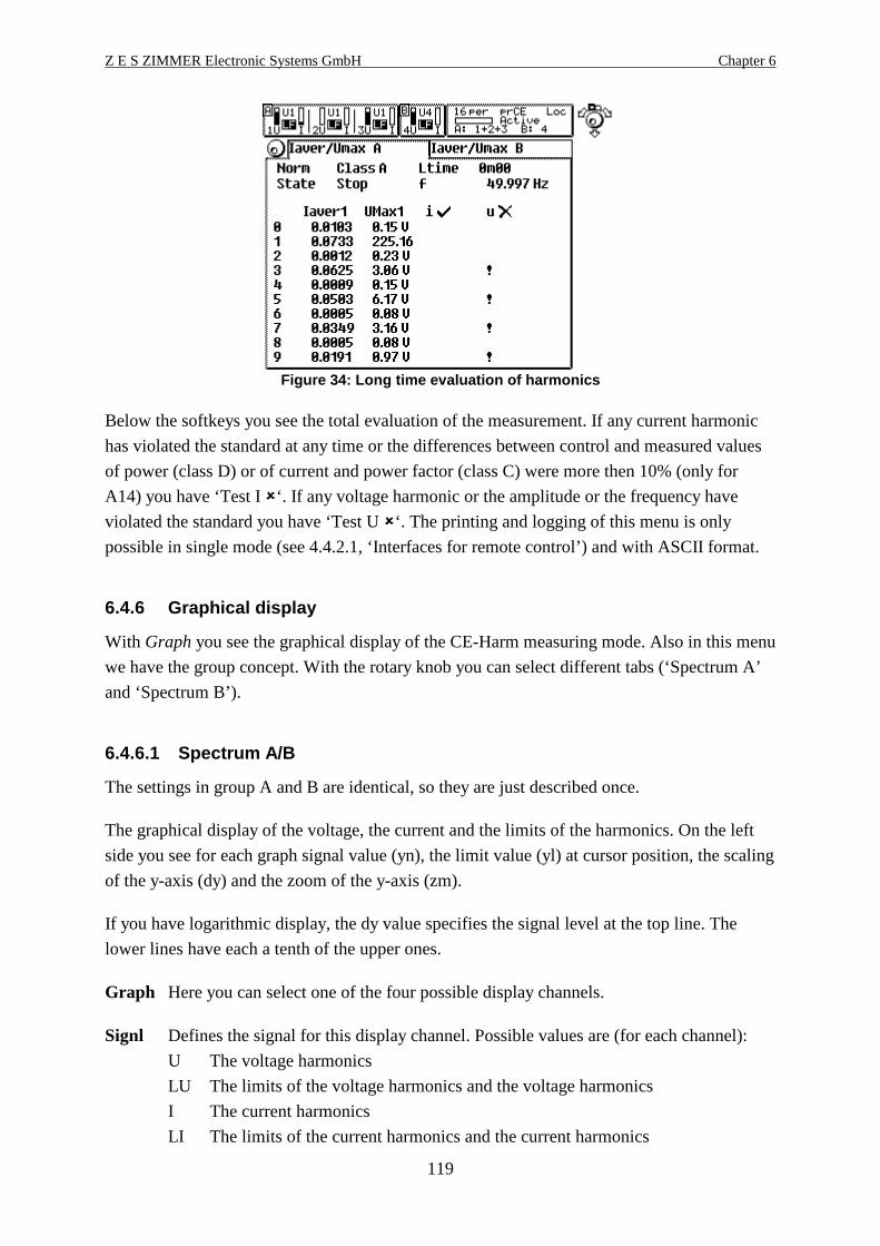
Z E S ZIMMER Electronic Systems GmbH Chapter 6
119
Figure 34: Long time evaluation of harmonics
Below the softkeys you see the total evaluation of the measurement. If any current harmonic
has violated the standard at any time or the differences between control and measured values
of power (class D) or of current and power factor (class C) were more then 10% (only for
A14) you have ‘Test I ‘. If any voltage harmonic or the amplitude or the frequency have
violated the standard you have ‘Test U ‘. The printing and logging of this menu is only
possible in single mode (see 4.4.2.1, ‘Interfaces for remote control’) and with ASCII format.
6.4.6 Graphical display
With Graph you see the graphical display of the CE-Harm measuring mode. Also in this menu
we have the group concept. With the rotary knob you can select different tabs (‘Spectrum A’
and ‘Spectrum B’).
6.4.6.1 Spectrum A/B
The settings in group A and B are identical, so they are just described once.
The graphical display of the voltage, the current and the limits of the harmonics. On the left
side you see for each graph signal value (yn), the limit value (yl) at cursor position, the scaling
of the y-axis (dy) and the zoom of the y-axis (zm).
If you have logarithmic display, the dy value specifies the signal level at the top line. The
lower lines have each a tenth of the upper ones.
Graph Here you can select one of the four possible display channels.
Signl Defines the signal for this display channel. Possible values are (for each channel):
U The voltage harmonics
LU The limits of the voltage harmonics and the voltage harmonics
I The current harmonics
LI The limits of the current harmonics and the current harmonics
CE-Harmonic measuring mode (option L50-O9) LMG500
120
For the displays with limits and harmonics you have always one thin bar with the
limit, one thin bar with the measuring value and again one thin bar with the limit. So
the value is covered by the limits.
You can imagine that the limits are displayed like a cup filled with water (which
represents the values). If you have too much in the cup you have a problem.
Zoom Allows you to zoom the signals in y direction
Move Allows you to move the cursor to another position.
Split You can have one graph in one big screen or you can have several graphs in several
screens (see pictures below)
Log changes between linear scaling (=off) and logarithmic scaling (=on) for the y-axis.
Figure 35: Graphical display of harmonics
6.4.6.2 Plot function
For the plot function we have the same rules like in the normal measuring mode (see ‘5.4.6.2,
Plot function’)
Z E S ZIMMER Electronic Systems GmbH Chapter 6
121
6.4.7 Custom menu
With Custom you see the custom menu. Here you can setup your own menus, calculate
formulas and execute programs. See 4.4.3, ‘Custom menu’ and 4.4.4, ‘Script/Formula editor’.
6.5 Storage of values
First you have to change to the menu you want to print out or to store and press Print/Log
(exact handling see 10, ‘Logging of values to drives, printer and interfaces’). All the values
you see in this menu are printed out. In the menues with harmonic values you get all
harmonics (not only the ones you see!).
6.6 Compliance tests according EN61000-3-2
For tests according to this standard you first have to change the Range to ‘Manual’ mode. This
is necessary because the test has to be done without any gaps.
Now you go to the Measuring menu, change the version with EN to ‘61000-3-2:1995’ or
‘61000-3-2:2006’ and select with Eval the class you want to test.
Now you can switch on the voltage. When the LMG is synchronised you can switch on the
equipment under test (EUT).
If you want to make long time evaluations you can start them with Start.


Z E S ZIMMER Electronic Systems GmbH Chapter 7
123
7 CE-Flicker measuring mode (option L50-O4)
In the CE-Flicker measuring mode the LMG500 works as an high precision flicker analyser
according to EN61000-4-15. The number of settings has been reduced to the needed ones to
avoid fail handling.
Note!In this measuring mode the valid frequency range is from 45 to 65Hz!
7.1 Measuring configuration (Measuring)
The synchronisation is fixed to the voltage channel. With the rotary knob you can only select
‘Globals’ tab.
7.1.1 Globals tab
Here the general settings are done.
dMax This selects the dmax limit for the measuring. This value has to be taken out of the
standard, depending on the measuring requirements.
EN Defines the standard which should be used:
3:95/-4-15 EN61000-3-3:1995 with EN61000-4-15:1998/A1:2003
3:08/-4-15 EN61000-3-3:2008 with EN61000-4-15:1998/A1:2003
3:08B2/-4-15 EN61000-3-3:2008 with EN61000-4-15:1998/A1:2003
This one is especially for tests according annex B.2
-11:2000 EN61000-3-11:2000 with EN61000-4-15:1998/A1:2003
Syst This selects the system which is used for the measurement. There are four possible
values:
230V/50Hz
230V/60Hz
120V/50Hz
120V/60Hz
The system is required for example for checking the correct frequency of the
measuring setup.
Intv This is the interval time of the short term flicker measuring. The standard value is
10min.

CE-Flicker measuring mode (option L50-O4) LMG500
124
Per. This is the number of short term periods for the long term measurement. The
standard value is 12 periods for a long term time of 2 hours.
Figure 36: Measuring menu in CE-Flicker mode
7.1.2 Ztest/Zref tab
This is only available when EN61000-3-11 is selected.
With Ztest you have to enter your actual used test impedance in Ω.
With Zref you have to choose, if your reference impedance is (0.24+j0.15)Ω or (0.4+j0.25)Ω.
The values for dc, dmax, Pst and Plt are recalculated as described in EN61000-3-11:2000
7.2 Measuring ranges (Range)
The settings are the same like in 5.2, ‘Measuring ranges (Range)’. Please note that the
standards require a continuous measuring without gaps. For that reason the auto range
function should be deactivated to prevent a range change, because this will cause a short
measurement with invalid values.
7.3 Definition of measuring values
The following basic definitions are used:
n The harmonic order.
T The time of an integer number of the periods of the synchronisation signal. The integer
factor depends on the standard EN61000-4-7. Actually 16 periods are measured.
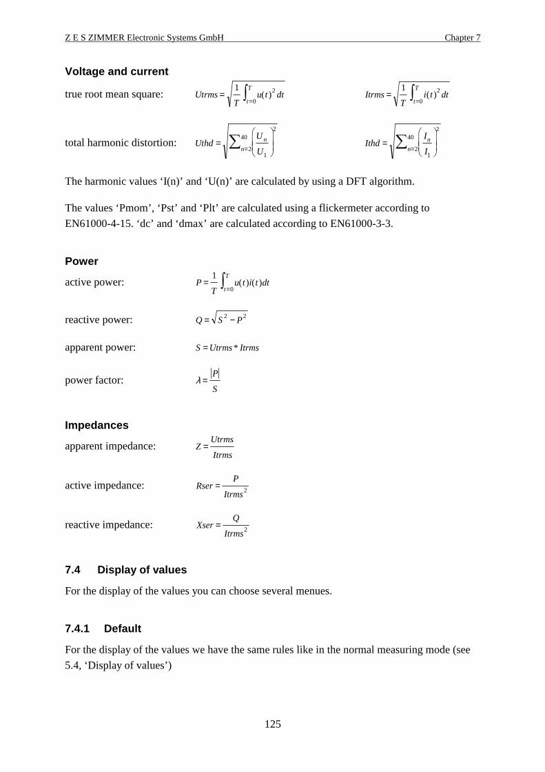
Z E S ZIMMER Electronic Systems GmbH Chapter 7
125
Voltage and current
true root mean square: UtrmsT
u t dtt
T=
=∫
1 2
0( ) Itrms
Ti t dt
t
T=
=∫
1 2
0( )
total harmonic distortion: UthdU
U
n
n=
=∑
1
2
2
40Ithd
I
I
n
n=
=∑
1
2
2
40
The harmonic values ‘I(n)’ and ‘U(n)’ are calculated by using a DFT algorithm.
The values ‘Pmom’, ‘Pst’ and ‘Plt’ are calculated using a flickermeter according to
EN61000-4-15. ‘dc’ and ‘dmax’ are calculated according to EN61000-3-3.
Power
active power: PT
u t i t dtt
T=
=∫
1
0( ) ( )
reactive power: Q S P= −2 2
apparent power: S Utrms Itrms= *
power factor: λ =P
S
Impedances
apparent impedance: ZUtrms
Itrms=
active impedance: RserP
Itrms= 2
reactive impedance: XserQ
Itrms= 2
7.4 Display of values
For the display of the values you can choose several menues.
7.4.1 Default
For the display of the values we have the same rules like in the normal measuring mode (see
5.4, ‘Display of values’)

CE-Flicker measuring mode (option L50-O4) LMG500
126
7.4.2 Voltage
Here you see the TRMS value, the THD and the frequency.
7.4.3 Current
Here you see the TRMS value, the THD and the frequency.
7.4.4 Power
For the display of the values we have the same rules like in the normal measuring mode (see
5.4, ‘Display of values’)
7.4.5 Flicker (Int. Val)
In this menu you see the flicker values of the equipment under test (EUT). You see the short
term flicker level Pst, the long term flicker level Plt, the actual flicker level Pmom, the relative
steady-state voltage change dc, the maximum relative voltage change dmax, the remaining long
term time, the remaining short term time and the state of the flicker measuring.
The state can be ‘starting’ (8s from pressing START), ‘running’ (while the long term interval)
and ‘stooped’ after the measuring.
Figure 37: Evaluation of flicker measurement
dmax is measured over the long term time.
dc is the relative voltage change between two ‘constant’ voltages. Therefore it can have
different values:
dc=------- means that there was no constant voltage.
dc=0.000% means that there was exactly one constant voltage.
Any other value is the biggest difference between two constant voltages.
Z E S ZIMMER Electronic Systems GmbH Chapter 7
127
Plt is calculated at the end of the long term measuring. Until then it is displayed as ‘-------’.
7.4.6 Graphical display
Here just the plot function is available. The handling is the same like described in 5.4.6,
‘Graphical display’
But there are some things to know concerning the displayed values:
In the other modes, all values are measured in the same time interval. In the flicker mode there
are two main time intervals: 10ms and 320ms. Most values are updated every 320ms, but
some come every 10ms: They are the momentary flicker level (ID is Pml) and the half wave
trms value (ID is Uhwl). As said above, this values come every 10ms. The Pmoml and Utrms
values are the average values of Pml and Uhwl. So you can see Pmoml and Pml in one graph
as function ‘A’ and ‘B’. Because Pmoml has a slower time base, it is plotted with 32 same
values.
7.4.7 Custom menu
With Custom you see the custom menu. Here you can setup your own menus, calculate
formulas and execute programs. See 4.4.3, ‘Custom menu’ and 4.4.4, ‘Script/Formula editor’.
7.5 Storage of values
First you have to change to the menu you want to print out or to store and press Print/Log
(exact handling see 10, ‘Logging of values to drives, printer and interfaces’). All the values
you see in this menu are printed out.
7.6 Tests according EN61000-3-3
For tests according to this standard you first have to change the Range to ‘Manual’ mode. This
is necessary because the test has to be done without any gaps.
Switch on the voltage of the EUT. Start the flicker process with Start. After a delay of 8s the
real measuring is started. Now you can switch on the EUT to get the different values. If you
want to stop the measuring before the end of the long term time just press Stop.
Annex B.2Usually the values dc and dmax run for the whole observation period (Plt-time). To simplify
tests according annex B.2 of EN61000-3-3:2008, you can choose, that these values are reset
after each short term observation periode. To do this, please select the B2 item in measuring
menu, softkey EN.


Z E S ZIMMER Electronic Systems GmbH Chapter 8
129
8 100 Harmonics measuring mode (option L50-O8)
In the 100 Harmonics measuring mode the LMG500 works as a high precision harmonic
analyser. The difference to the CE mode is, that 100 harmonics, the phase angles and the
power harmonics are measured. The frequency range is much wider. There is no check against
any limits.
8.1 Measuring configuration (Measuring)
When you came to this menu by pressing Measure you first have to choose MODE and then
HARM to enter this mode. The well known setting menu with the three tabs („Globals“,
„Group A“ and „Group B“) opens:
Globals Here you can set up the wiring in which is measured.
Group A/B For the settings in this menu refer 5.1.2 Group A/B/C/D tab. Additional
settings are possible:
FDiv This defines a frequency divider for the basic wave. With a value of 1
the measured frequency is identical to the basic wave. With a value of 2
the fundamental has only the half frequency of the measured frequency
(e.g. A 50Hz signal with FDiv = 4 is analysed on a 12.5Hz base. So you
get 3 interharmonic between the 50Hz Harmonics)
Only with FDIV set to 1 you get the THD values of the signals
Filt Defines the active filter:
Auto: A sufficient anti aliasing filter will be selected.
other values: The chosen filter will be activated. CAUTION: with a
wrong filter setting you might get aliasing!
Pressing the rotary knob you will get to the main menu.

100 Harmonics measuring mode (option L50-O8) LMG500
130
Figure 38: Measuring menu in Harm100 mode
8.2 Measuring ranges (Range)
The settings are the same like in 5.2, ‘Measuring ranges (Range)5.2’, but in this mode you
have no autorange function.
8.3 Definition of measuring values
The following basic definitions are used:
n The harmonic order.
T The time of an integer number of the periods of the synchronisation signal. The integer
factor depends on the frequency of the basic wave:

Z E S ZIMMER Electronic Systems GmbH Chapter 8
131
Basic wave range / Hz Number of measured
periods
Sample frequency
divider
Automatically
selected filter
640-1280 32 1 HF-Rejection
320-640 16 1 HF-Rejection
160-320 8 1 HF-Rejection
80-160 4 1 HF-Rejection
40-80 4 2 18kHz
20-40 4 4 6kHz
10-20 4 8 2.8kHz
5-10 4 16 1.4kHz
2.5-5 4 32 700Hz
1.25-2.5 4 64 350Hz
0.625-1.25 4 128 175Hz
0.3125-0.625 4 256 87.5Hz
0.15625-0.3125 2 256 87.5Hz
0.078125-0.15625 1 256 87.5Hz
The ‘sample frequency divider’ defines, how the sampling frequency of about 100kHz is
divided for this measuring.
Voltage and current
true root mean square: UtrmsT
u t dtt
T=
=∫
1 2
0( ) Itrms
Ti t dt
t
T=
=∫
1 2
0( )
total harmonic distortion: ∑ =
= 99
2
2
1n
n
U
UUthd ∑ =
= 99
2
2
1n
n
I
IIthd
Only with FDIV set to 1 you get the THD values of the signals.
The harmonic components are calculated to meet the following:
u t Un n tn un( ) sin( )= = +∑ 2099 ω ϕ i t In n tn in( ) sin( )= = +∑ 20
99 ω ϕ
The harmonic values ‘I(n)’, ‘U(n)’ and ‘Phase(n)’ are calculated by using a DFT algorithm.
With this values also the values of ‘P(n)’, ‘S(n)’ and ‘Q(n)’ are calculated. This ‘Q(n)’ is only
the reactive power, caused by a phase shift of a voltage and current component with the same
frequency. Therefore it is in this mode possible to calculate also the reactive power which is
caused by voltage and current components with different frequencies. This value is called D:
D S P Qshift= − −2 2 2 with Qshift Q nn
==
∑ ( )0
99
, P and S see below.
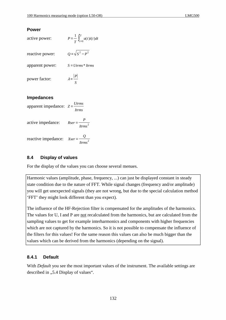
100 Harmonics measuring mode (option L50-O8) LMG500
132
Power
active power: PT
u t i t dtt
T=
=∫1
0( ) ( )
reactive power: Q S P= −2 2
apparent power: S Utrms Itrms= *
power factor: λ =P
S
Impedances
apparent impedance:ZUtrms
Itrms=
active impedance: RserP
Itrms= 2
reactive impedance:XserQ
Itrms= 2
8.4 Display of values
For the display of the values you can choose several menues.
Harmonic values (amplitude, phase, frequency, ...) can just be displayed constant in steady
state condition due to the nature of FFT. While signal changes (frequency and/or amplitude)
you will get unexpected signals (they are not wrong, but due to the special calculation method
‘FFT’ they might look different than you expect).
The influence of the HF-Rejection filter is compensated for the amplitudes of the harmonics.
The values for U, I and P are not recalculated from the harmonics, but are calculated from the
sampling values to get for example interharmonics and components with higher frequencies
which are not captured by the harmonics. So it is not possible to compensate the influence of
the filters for this values! For the same reason this values can also be much bigger than the
values which can be derived from the harmonics (depending on the signal).
8.4.1 Default
With Default you see the most important values of the instrument. The available settings are
described in „5.4 Display of values“.
Z E S ZIMMER Electronic Systems GmbH Chapter 8
133
8.4.2 Voltage
With Voltage you see the harmonic values of the measured voltage and in the second row the
phase of the harmonic component.
With the softkey Chns you can choose the channel.
With the softkey Href you can select the reference signal (voltage, current or none). The
fundamental of this signal is always set to 0°. When selected ‘none’, the time window is the
reference.
With the softkey Link the harmonics of the linked values will be shown.
Using the rotary knob you can scroll through the list to see all harmonics.
8.4.3 Current
With Current you see the harmonic values of the measured current and in the second row the
phase of the harmonic component.
With the softkey Chns you can choose the channel.
With the softkey Href you can select the reference signal (voltage, current or none). The
fundamental of this signal is always set to 0°. When selected ‘none’, the time window is the
reference.
With the softkey Link the harmonics of the linked values will be shown.
Using the rotary knob you can scroll through the list to see all harmonics.
8.4.4 Power
With Power you see the harmonic values of the measured powers. The synchronisation
frequency is shown in the first row, displaying all channels.
With the softkey Chns you can choose the channel.
With List you can choose several lists with the different combinations of the different powers.
Using the rotary knob you can scroll through the list to see all harmonics.
Please noteThe harmonics of the power are not the results of a fourier transformation of the power
waveform, but are calculated by same frequent voltage and current harmonics.

100 Harmonics measuring mode (option L50-O8) LMG500
134
8.4.5 Graphical display
Here just the plot function, the spectrum and the vector diagram is available. The handling is
the same like described in 5.4.6, ‘Graphical display’ and 6.4.6.1, ‘Spectrum A/B’.
Figure 39: Graphical display of harmonics
8.4.6 Custom menu
With Custom you see the custom menu. Here you can setup your own menus, calculate
formulas and execute programs. See 4.4.3, ‘Custom menu’ and 4.4.4, ‘Script/Formula editor’.
8.5 Storage of values
First you have to change to the menu you want to print out or to store and press Print/Log
(exact handling see 10, ‘Logging of values to drives, printer and interfaces’). All the values
you see in this menu are printed out. In the menues with harmonic values you get all
harmonics (not only the ones you see!).

Z E S ZIMMER Electronic Systems GmbH Chapter 9
135
9 Interfaces (IEEE option L50-O1)
With exception of the IEEE interface all interfaces could also be used for data logging (see 10,
‘Logging of values to drives, printer and interfaces’). To remote control the LMG please
reserve first the wished interface for this job (see 4.4.2.1, ‘Interfaces for remote control’).
This chapter includes all commands and a short general syntax description. A much more
detailed syntax description with a lot of examples and further programming explanations can
be found in our Programmer’s Guide on the CD which is included in the printed version of
this manual. If this is missing or you have just a PDF version of this manual you can request
the Programmer’s Guide by email from ‘[email protected]’.
9.1 Short syntax description
There are two implemented languages: SCPI and SHORT. When switching on the instrument
SCPI is selected. To change to SHORT you have to send:
SYST:LANG SHORT
For further differences between SCPI and SHORT command set see also 9.2.4, ‘:FETCh and
:READ commands’
The general syntax for both command sets is identical. The most important syntax rules are:
• A message to the instrument has to be terminated with an EOS character.
• brackets [..] are showing optional part of commands. There is no need to send them to the
device, but you can do it, if you need this function. The brackets are just informative and
should not be sent.
• The number of the measuring channel (further on called ‘suffix’) follows directly (without
any space) after the identifier. If you don’t specify one, ‘1’ is assumed.
• If you request a value you have to add a ‘?’ directly behind the suffix (or the identifier, if
no suffix is specified), without any space.
• All parameters following the commands have to be separated from the command with at
least one space character.
• The group number is usually an optional parameter in the format [,<NRi>]. If you don’t
specify it, group A (=0) is assumed as default value.
• ‘/qonly/’ indicates, that this is a value which can only be demanded, but not set. Do not
send the ‘/qonly/’ string to the device, it is just written in this manual to explain the
command.
For example you can’t send a measuring value.
Interfaces (IEEE option L50-O1) LMG500
136
• ‘/nquery/’ indicates that this value can only be set, and not demanded. Do not send the
‘/nquery/’ string to the device, it is just written in this manual to explain the command.
For example you can’t request a trigger command.
• All commands without ‘/qonly/’ and ‘/nquery/’ can be read and set.
• <NRf> are float numbers
• <NRi> are integer numbers
• <list> stands for <(<NRf>:<NRf>)>. With this construct you can request several values
which are stored in an array, for example harmonic values. To get the 3rd to 11th harmonic
of the voltage of the second measuring channel you have to write in SHORT command set:
HUAM2? (3:11)
For the complete syntax rules please take a look at the Programmer’s Guide!
Examples showing the syntaxEquivalent SCPI commands for reading the TRMS value of the 1st measuring channel::FETCh:CURRent:TRMS?:FETC:CURR:TRMS?:FETC:CURR:TRMS1?As SHORT command it would beITRMS? or ITRMS1?Please note that there is no space before the ‘1’ and no space before the ‘?’!
Command for reading the harmonic voltages from the 2nd to the 4th harmonic (3 values)::FETC:HARM:VOLT:AMPL? (2:4)Please notice that there is at least one space between the question mark and theparameters!
Command for setting the 250V range::SENS:VOLT:RANG 250Please notice that there is at least one space before the parameter 250!
Command for setting the 250V range in the 3rd channel::SENS:VOLT:RANG3 250Please notice that there is no space before the suffix and at least one space before the250!
Commands for setting and reading a filter in group B (short language):FILT 5,1FILT? 1For group A you can write:FILT 5,0 or FILT 5FILT? 0 or FILT?
For more examples please take a look at the Programmer’s Guide!
Z E S ZIMMER Electronic Systems GmbH Chapter 9
137
9.2 Commands
Here you find all commands the instrument can handle. The commands are ordered like in the
SCPI tree structure. The description is always the same:
SCPI: The SCPI syntax of the commandSHORT: The SHORT syntax of the command
ID: The ID for script editor and similar Mode: The valid measuring modesType: The data type Suffix: The valid suffix rangeValue: The value range List: The valid list rangeUnit: The physical unit Group: The valid group range
An ‘n/a’ means ‘not applicable’. If you for example see an ‘n/a’ in the ‘Value:’ field, then this
command has no value at all. Or it is a float number with all valid codes according IEEE754.
The titles of the useable commands are in a box. There you find from left to right: SCPI
command, SHORT command and the ID if existing.
Please see also 9.1, ‘Short syntax description’.
For all this commands there is a separated index. See chapter 16, ‘Interface commandindex’.
9.2.1 IEEE488.2 common commands
This are commands which are defined in IEEE488.2, but they are pure ASCII commands and
can also be sent via other interfaces like RS232.
9.2.1.1 *CLS *CLS
SCPI: *CLS/nquery/SHORT: *CLS/nquery/
ID: n/a Mode: allType: n/a Suffix: n/aValue: n/a List: n/aUnit: n/a Group: n/a
Clears the event registers of all status data structures in a device and the error/event queue.
9.2.1.2 *ESE *ESE
SCPI: *ESE <NRi>SHORT: *ESE <NRi>
ID: n/a Mode: n/aType: long int Suffix: n/aValue: 0...255 List: n/aUnit: n/a Group: n/a

Interfaces (IEEE option L50-O1) LMG500
138
Used to set up or read out the Event Status Enable Register.
9.2.1.3 *ESR? *ESR?
SCPI: *ESR? /qonly/SHORT: *ESR? /qonly/
ID: n/a Mode: allType: long int Suffix: n/aValue: 0...255 List: n/aUnit: n/a Group: n/a
Reads out and clears the Event Status Register.
9.2.1.4 *IDN? *IDN?
SCPI: *IDN? /qonly/SHORT: *IDN? /qonly/
ID: n/a Mode: allType: n/a Suffix: n/aValue: n/a List: n/aUnit: n/a Group: n/a
Reads out the identification of the device. There are 4 fields separated by commas:
Field 1 Manufacturer
Field 2 Model
Field 3 Serial number
Field 4 Firmware level
9.2.1.5 *IST? *IST?
SCPI: *IST? /qonly/SHORT: *IST? /qonly/
ID: n/a Mode: allType: long int Suffix: n/aValue: 0, 1 List: n/aUnit: n/a Group: n/a
Individual Status Query. This returns the status of the ‘ist’ local message in the device.
9.2.1.6 *OPC *OPC
SCPI: *OPC/nquery/SHORT: *OPC/nquery/
ID: n/a Mode: allType: n/a Suffix: n/aValue: n/a List: n/aUnit: n/a Group: n/a
Z E S ZIMMER Electronic Systems GmbH Chapter 9
139
Causes the device to set the operation complete bit in the Standard Event Status Register,
when all pending selected device operations have been finished.
9.2.1.7 *OPC? *OPC?
SCPI: *OPC? /qonly/SHORT: *OPC?/qonly/
ID: n/a Mode: allType: char Suffix: n/aValue: ‘1’ List: n/aUnit: n/a Group: n/a
Causes the device to place a „1“ (=31h) in the output queue, when all pending selected device
actions have been finished (=operation complete). This is independent from the output format!
9.2.1.8 *PRE *PRE
SCPI: *PRE <NRi>SHORT: *PRE <NRi>
ID: n/a Mode: allType: long int Suffix: n/aValue: 0...65535 List: n/aUnit: n/a Group: n/a
Used to set up or read out the Parallel Poll Enable Register
9.2.1.9 *RST *RST
SCPI: *RST/nquery/SHORT: *RST/nquery/
ID: n/a Mode: allType: n/a Suffix: n/aValue: n/a List: n/aUnit: n/a Group: n/a
This performs a device reset. A lot of internal settings (like measuring mode, ranges, ...) are
set to their default values. In this chapters the default value is indicated by ‘[*RST Default
value]’. All time dependent measurements are stopped (energy, flicker, harmonics).
The interface and it’s parameters are not reset! If you want to reset it, please use a BREAK
with RS232 interface or a ‘device clear’ with IEEE interface.
HintThe execution of this command can take up to several seconds. The LMG works internally
with a watchdog protection. To prevent that the watchdog becomes active, the ‘*RST’
command should be send as the only command in a message. Just the ‘*OPC?’ can be added

Interfaces (IEEE option L50-O1) LMG500
140
to get a feedback, if the command has finished (‘*RST;*OPC?’). In this case wait until the ‘1’
returns before sending the next commands!
9.2.1.10 *SRE *SRE
SCPI: *SRE <NRi>SHORT: *SRE <NRi>
ID: n/a Mode: allType: long int Suffix: n/aValue: 0...255 List: n/aUnit: n/a Group: n/a
Sets or queries the Service Request Enable Register
9.2.1.11 *STB? *STB?
SCPI: *STB? /qonly/SHORT: *STB? /qonly/
ID: n/a Mode: allType: long int Suffix: n/aValue: 0...255 List: n/aUnit: n/a Group: n/a
Queries the Status Byte Register.
9.2.1.12 *TRG *TRG
SCPI: *TRG/nquery/SHORT: *TRG/nquery/
ID: n/a Mode: allType: n/a Suffix: n/aValue: n/a List: n/aUnit: n/a Group: n/a
Triggers the same action that happens when programmer sends DT1 via IEEE488.1 interface
or ‘&TRG<cr><lf>‘ via RS232 interface. Actually nothing is performed.
9.2.1.13 *TST? *TST?
SCPI: *TST? /qonly/ <NRi>SHORT: *TST?/qonly/ <NRi>
ID: n/a Mode: allType: long int Suffix: n/aValue: n/a List: n/aUnit: n/a Group: n/a
Initiates a self test. Returns a value depending on <NRi>. This command should only be used
by ZES and not by customers.

Z E S ZIMMER Electronic Systems GmbH Chapter 9
141
9.2.1.14 *WAI *WAI
SCPI: *WAI/nquery/SHORT: *WAI/nquery/
ID: n/a Mode: allType: n/a Suffix: n/aValue: n/a List: n/aUnit: n/a Group: n/a
Waits until all pending selected device operations have been finished. Note: The instrument
handles commands in a queue, so when executing the *WAI all previous commands have
been executed. Thus the instrument is doing nothing when receiving the *WAI command. It
has been implemented to follow the standard IEEE488.2.
9.2.2 :CALCulate commands
Here you find commands which influence the script editor (formulas) or limits.
:CALCulate →→→→ :ENVironment:DISPlay :FORMula:FETCh :LIMit:FORMat:INITiate:INPut:INSTrument:MEMory:READ:SENSe:SOURce:STATus:SYSTem:TRIGger
9.2.2.1.1 ENVironment ENV Env
SCPI: :CALCulate:ENVironment <NRf>[,<NRi>]SHORT: ENV <NRf>[,<NRi>]
ID: Env Mode: allType: float Suffix: n/aValue: n/a List: n/aUnit: n/a Group: optional [,<NRi>]: 0=Env0, ... ,7=Env7
Sets or queries an environment variable.
9.2.2.2 :FORMula
:CALCulate →→→→ :ENVironment
:DISPlay :FORMula →→→→ [:DEFine]
:FETCh :LIMit:FORMat:INITiate:INPut:INSTrument:MEMory

Interfaces (IEEE option L50-O1) LMG500
142
:READ:SENSe:SOURce:STATus:SYSTem:TRIGger
9.2.2.2.1 [:DEFine] FORM
SCPI: :CALCulate:FORMula[:DEFine] <string program data>SHORT: FORM<string program data>
ID: n/a Mode: allType: string Suffix: n/aValue: n/a List: n/aUnit: n/a Group: n/a
Sets or reads the script of the script editor. There is no *RST default value.
For example ‘FORM „a=1;“<lf>‘ sets the internal variable a to 1.
9.2.2.3 :LIMit:
:CALCulate →→→→ :ENVironment
:DISPlay :FORMula:FETCh :LIMit →→→→ :CLASs
:FORMat :DMAX:INITiate :FCURrent:INPut :PFACtor:INSTrument :POWer:MEMory :SYSTem:READ :VERSion:SENSe:SOURce:STATus:SYSTem:TRIGger
9.2.2.3.1 :CLASs EVAL
SCPI: :CALCulate:LIMit:CLASs <NRi>SHORT: EVAL <NRi>
ID: n/a Mode: CEType: long int Suffix: n/aValue: 0...6, 10...12 List: n/aUnit: n/a Group: n/a
Sets the evaluation of the harmonics in the CE-Harm mode:
0: Class A (EN61000-3-2) [*RST default value]
1: Class B (EN61000-3-2)
2: Class C-2 (EN61000-3-2)
3: Class D (EN61000-3-2)
4: Class C-3 (EN61000-3-2)
5: Class C-W (EN61000-3-2)

Z E S ZIMMER Electronic Systems GmbH Chapter 9
143
6: Class C-1 (EN61000-3-2)
10: Table 2 (EN61000-3-12)
11: Table 3 (EN61000-3-12)
12: Table 4 (EN61000-3-12)
9.2.2.3.2 :DMAX FLDL
SCPI: :CALCulate:LIMit:DMAX <NRf>SHORT: FLDL <NRf>
ID: n/a Mode: FlickerType: float Suffix: n/aValue: in % List: n/aUnit: n/a Group: n/a
Sets the allowed limit for dmax for the device under test according to the standard in the flicker
mode.
9.2.2.3.3 :FCURrent ISO
SCPI: :CALCulate:LIMit:FCURrent <NRf>SHORT: ISO <NRf>
ID: n/a Mode: CE-HarmType: float Suffix: 1...8Value: n/a, [*RST default value] = 1.0 List: n/aUnit: A Group: n/a
Sets or reads the fundamental current for the EN61000-3-2:2006 limit calculation in the CE
mode.
9.2.2.3.4 :FVERsion FNRM
SCPI: :CALCulate:LIMit:FVERsion <NRi>SHORT: FNRM <NRi>
ID: n/a Mode: FlickerType: long int Suffix: n/aValue: 0...3 List: n/aUnit: n/a Group: n/a
Sets or reads the edition of the flicker standard:
0: EN61000-3-3:1995 [*RST default value]
1: EN61000-3-3:2008
2: EN61000-3-3:2008 Annex B.2
3: EN61000-3-11:2000
9.2.2.3.5 :PFACtor PFSO
SCPI: :CALCulate:LIMit:PFACtor <NRf>
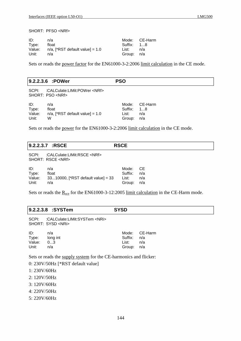
Interfaces (IEEE option L50-O1) LMG500
144
SHORT: PFSO <NRf>
ID: n/a Mode: CE-HarmType: float Suffix: 1...8Value: n/a, [*RST default value] = 1.0 List: n/aUnit: n/a Group: n/a
Sets or reads the power factor for the EN61000-3-2:2006 limit calculation in the CE mode.
9.2.2.3.6 :POWer PSO
SCPI: :CALCulate:LIMit:POWer <NRf>SHORT: PSO <NRf>
ID: n/a Mode: CE-HarmType: float Suffix: 1...8Value: n/a, [*RST default value] = 1.0 List: n/aUnit: W Group: n/a
Sets or reads the power for the EN61000-3-2:2006 limit calculation in the CE mode.
9.2.2.3.7 :RSCE RSCE
SCPI: :CALCulate:LIMit:RSCE <NRf>SHORT: RSCE <NRf>
ID: n/a Mode: CEType: float Suffix: n/aValue: 33...10000, [*RST default value] = 33 List: n/aUnit: n/a Group: n/a
Sets or reads the Rsce for the EN61000-3-12:2005 limit calculation in the CE-Harm mode.
9.2.2.3.8 :SYSTem SYSD
SCPI: :CALCulate:LIMit:SYSTem <NRi>SHORT: SYSD <NRi>
ID: n/a Mode: CE-HarmType: long int Suffix: n/aValue: 0...3 List: n/aUnit: n/a Group: n/a
Sets or reads the supply system for the CE-harmonics and flicker:
0: 230V/50Hz [*RST default value]
1: 230V/60Hz
2: 120V/50Hz
3: 120V/60Hz
4: 220V/50Hz
5: 220V/60Hz

Z E S ZIMMER Electronic Systems GmbH Chapter 9
145
6: 240V/50Hz
7: 240V/60Hz
9.2.2.3.9 :VERSion EDIT
SCPI: :CALCulate:LIMit:VERSion <NRi>SHORT: EDIT <NRi>
ID: n/a Mode: CEType: long int Suffix: n/aValue: 0...4 List: n/aUnit: n/a Group: n/a
Sets or reads the edition of the harmonic standard:
0: EN61000-3-2:1995 and EN61000-4-7:1993 [*RST default value]
1: EN61000-3-2:1995 and EN61000-4-7:2008
2: EN61000-3-2:2006 and EN61000-4-7:1993
3: EN61000-3-2:2006 and EN61000-4-7:2008
4: EN61000-3-12:2005 and EN61000-4-7:2008
9.2.2.3.10 :ZREF ZREF
SCPI: :CALCulate:LIMit:ZREF <NRf>SHORT: ZREF <NRf>
ID: n/a Mode: FlickerType: int Suffix: n/aValue: 0, 1 List: n/aUnit: n/a Group: n/a
Sets or reads the Zref for the EN61000-3-11:2000 limit calculation.
0: (0.24+j0.15)Ω [*RST default value]
1: (0.40+j0.25)Ω
9.2.2.3.11 :ZTESt ZTST
SCPI: :CALCulate:LIMit:ZTESt <NRf>SHORT: ZTST <NRf>
ID: n/a Mode: FlickerType: float Suffix: n/aValue: 0.001...2, [*RST default value] = 0.283 List: n/aUnit: Ω Group: n/a
Sets or reads the Ztest for the EN61000-3-11:2000 limit calculation.
9.2.3 :DISPlay commands
:CALCulate
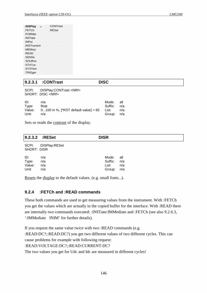
Interfaces (IEEE option L50-O1) LMG500
146
:DISPlay →→→→ :CONTrast
:FETCh :RESet:FORMat:INITiate:INPut:INSTrument:MEMory:READ:SENSe:SOURce:STATus:SYSTem:TRIGger
9.2.3.1 :CONTrast DISC
SCPI: :DISPlay:CONTrast <NRf>SHORT: DISC <NRf>
ID: n/a Mode: allType: float Suffix: n/aValue: 0...100 in %, [*RST default value] = 65 List: n/aUnit: n/a Group: n/a
Sets or reads the contrast of the display.
9.2.3.2 :RESet DISR
SCPI: :DISPlay:RESetSHORT: DISR
ID: n/a Mode: allType: n/a Suffix: n/aValue: n/a List: n/aUnit: n/a Group: n/a
Resets the display to the default values. (e.g. small fonts...).
9.2.4 :FETCh and :READ commands
These both commands are used to get measuring values from the instrument. With :FETCh
you get the values which are actually in the copied buffer for the interface. With :READ there
are internally two commands executed: :INITiate:IMMediate and :FETCh (see also 9.2.6.3,
‘:IMMediate INIM’ for further details).
If you request the same value twice with two :READ commands (e.g.
:READ:DC?;:READ:DC?) you get two different values of two different cycles. This can
cause problems for example with following request:
:READ:VOLTAGE:DC?;:READ:CURRENT:DC?
The two values you get for Udc and Idc are measured in different cycles!

Z E S ZIMMER Electronic Systems GmbH Chapter 9
147
If you request the same value twice with two :FETCh commands you get the same values of
the same cycle. For example :FETC:DC?;:FETC:DC? would not make any sense, because you
will get the same value.
A usual request looks like this:
:READ:VOLTAGE:DC?;:FETC:CURRENT:DC?
In this case the instrument finishes the actual cycle, copies the values for the interface and
returns the two requested values. This two values are measured in the same cycle!
The SHORT commands perform equal to the :FETCh commands (which means there isno INIM performed!). So if you want to perform the last example with SHORTcommands you have to enterINIM;UDC?;IDC?
9.2.4.1 [:SCALar]
9.2.4.1.1 :CURRent
:CALCulate:DISPlay
:FETCh →→→→ [:SCALar] →→→→ :CURRent →→→→ :AC
:FORMat :CYCLe :CFACtor:INITiate :DINPut :DC:INPut :ENERgy :FFACtor:INSTrument :FLICker :INRush:MEMory :FREQuency :MAXPk
:READ →→→→ :HARMonics :MINPk
:SENSe :POWer :PPEak:SOURce :RESistance :RECTify:STATus :SSYStem :RUSed:SYSTem :VARiable [:TRMS]:TRIGger [:VOLTage]
9.2.4.1.1.1 :AC? IAC? Iac
SCPI: :FETCh[:SCALar]:CURRent:AC? /qonly/ | :READ[:SCALar]:CURRent:AC? /qonly/SHORT: IAC? /qonly/
ID: Iac Mode: Normal, CE-HarmType: float Suffix: 1...14Value: n/a List: n/aUnit: A Group: n/a
Reads the AC value of the current.
9.2.4.1.1.2 :CFACtor? ICF? Icf
SCPI: :FETCh[:SCALar]:CURRent:CFACtor? /qonly/ | :READ[:SCALar]:CURRent:CFACtor? /qonly/SHORT: ICF?/qonly/
ID: Icf Mode: NormalType: float Suffix: 1...14
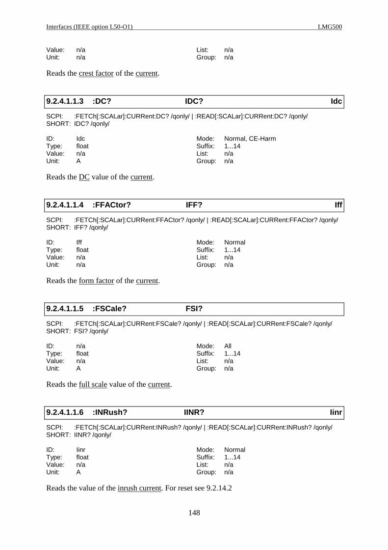
Interfaces (IEEE option L50-O1) LMG500
148
Value: n/a List: n/aUnit: n/a Group: n/a
Reads the crest factor of the current.
9.2.4.1.1.3 :DC? IDC? Idc
SCPI: :FETCh[:SCALar]:CURRent:DC? /qonly/ | :READ[:SCALar]:CURRent:DC? /qonly/SHORT: IDC? /qonly/
ID: Idc Mode: Normal, CE-HarmType: float Suffix: 1...14Value: n/a List: n/aUnit: A Group: n/a
Reads the DC value of the current.
9.2.4.1.1.4 :FFACtor? IFF? Iff
SCPI: :FETCh[:SCALar]:CURRent:FFACtor? /qonly/ | :READ[:SCALar]:CURRent:FFACtor? /qonly/SHORT: IFF? /qonly/
ID: Iff Mode: NormalType: float Suffix: 1...14Value: n/a List: n/aUnit: n/a Group: n/a
Reads the form factor of the current.
9.2.4.1.1.5 :FSCale? FSI?
SCPI: :FETCh[:SCALar]:CURRent:FSCale? /qonly/ | :READ[:SCALar]:CURRent:FSCale? /qonly/SHORT: FSI? /qonly/
ID: n/a Mode: AllType: float Suffix: 1...14Value: n/a List: n/aUnit: A Group: n/a
Reads the full scale value of the current.
9.2.4.1.1.6 :INRush? IINR? Iinr
SCPI: :FETCh[:SCALar]:CURRent:INRush? /qonly/ | :READ[:SCALar]:CURRent:INRush? /qonly/SHORT: IINR? /qonly/
ID: Iinr Mode: NormalType: float Suffix: 1...14Value: n/a List: n/aUnit: A Group: n/a
Reads the value of the inrush current. For reset see 9.2.14.2
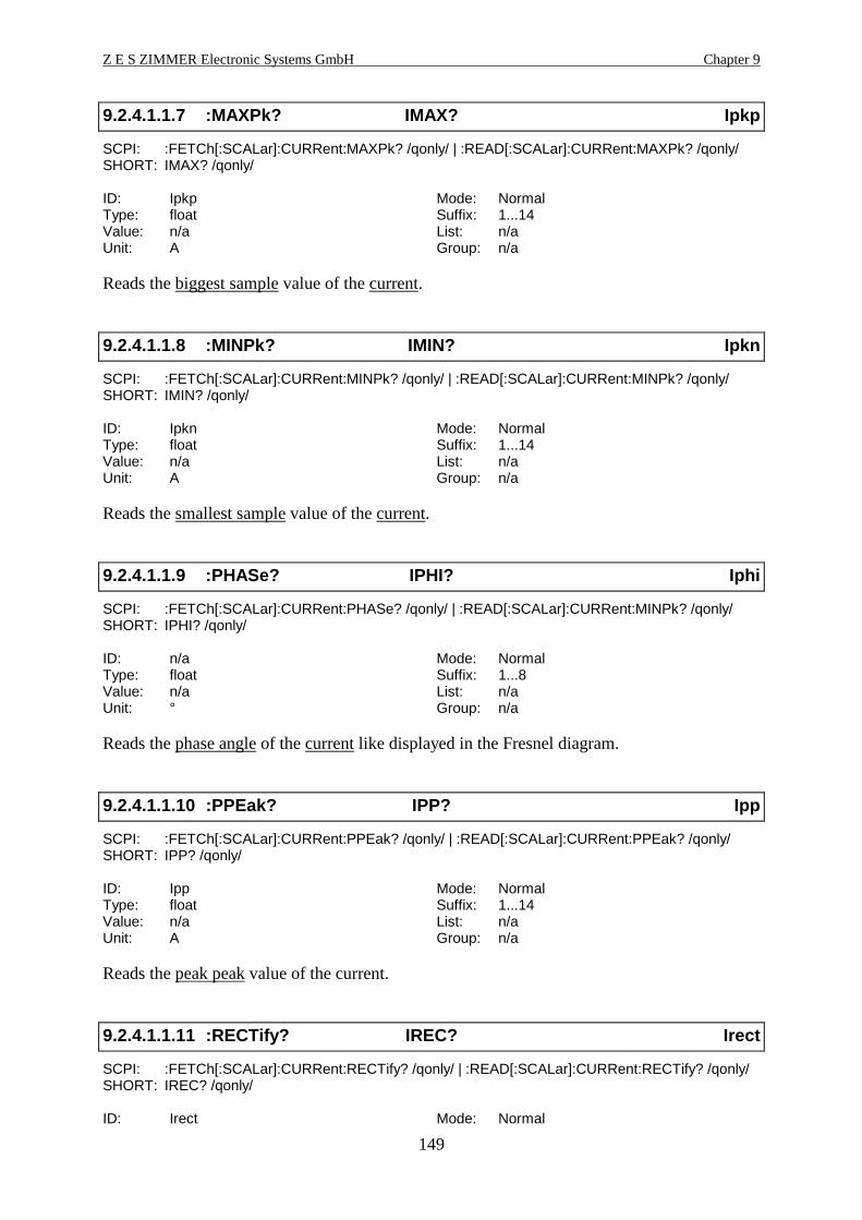
Z E S ZIMMER Electronic Systems GmbH Chapter 9
149
9.2.4.1.1.7 :MAXPk? IMAX? Ipkp
SCPI: :FETCh[:SCALar]:CURRent:MAXPk? /qonly/ | :READ[:SCALar]:CURRent:MAXPk? /qonly/SHORT: IMAX? /qonly/
ID: Ipkp Mode: NormalType: float Suffix: 1...14Value: n/a List: n/aUnit: A Group: n/a
Reads the biggest sample value of the current.
9.2.4.1.1.8 :MINPk? IMIN? Ipkn
SCPI: :FETCh[:SCALar]:CURRent:MINPk? /qonly/ | :READ[:SCALar]:CURRent:MINPk? /qonly/SHORT: IMIN? /qonly/
ID: Ipkn Mode: NormalType: float Suffix: 1...14Value: n/a List: n/aUnit: A Group: n/a
Reads the smallest sample value of the current.
9.2.4.1.1.9 :PHASe? IPHI? Iphi
SCPI: :FETCh[:SCALar]:CURRent:PHASe? /qonly/ | :READ[:SCALar]:CURRent:MINPk? /qonly/SHORT: IPHI? /qonly/
ID: n/a Mode: NormalType: float Suffix: 1...8Value: n/a List: n/aUnit: ° Group: n/a
Reads the phase angle of the current like displayed in the Fresnel diagram.
9.2.4.1.1.10 :PPEak? IPP? Ipp
SCPI: :FETCh[:SCALar]:CURRent:PPEak? /qonly/ | :READ[:SCALar]:CURRent:PPEak? /qonly/SHORT: IPP? /qonly/
ID: Ipp Mode: NormalType: float Suffix: 1...14Value: n/a List: n/aUnit: A Group: n/a
Reads the peak peak value of the current.
9.2.4.1.1.11 :RECTify? IREC? Irect
SCPI: :FETCh[:SCALar]:CURRent:RECTify? /qonly/ | :READ[:SCALar]:CURRent:RECTify? /qonly/SHORT: IREC? /qonly/
ID: Irect Mode: Normal
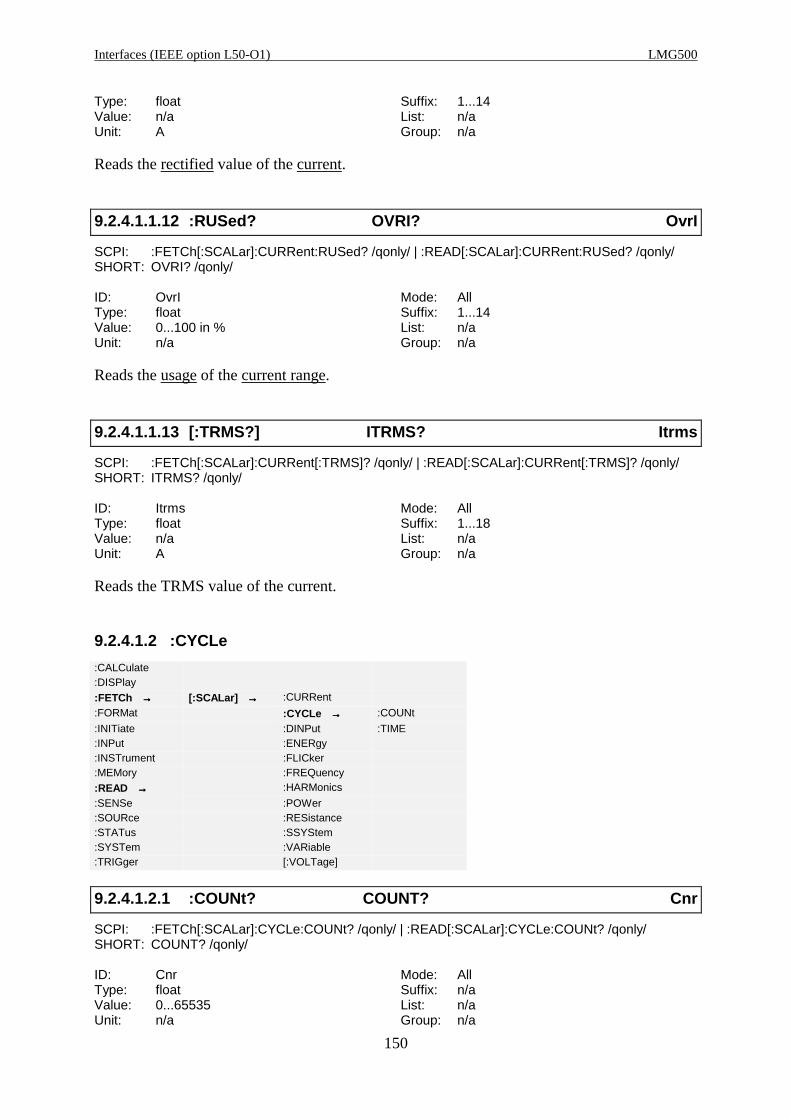
Interfaces (IEEE option L50-O1) LMG500
150
Type: float Suffix: 1...14Value: n/a List: n/aUnit: A Group: n/a
Reads the rectified value of the current.
9.2.4.1.1.12 :RUSed? OVRI? OvrI
SCPI: :FETCh[:SCALar]:CURRent:RUSed? /qonly/ | :READ[:SCALar]:CURRent:RUSed? /qonly/SHORT: OVRI? /qonly/
ID: OvrI Mode: AllType: float Suffix: 1...14Value: 0...100 in % List: n/aUnit: n/a Group: n/a
Reads the usage of the current range.
9.2.4.1.1.13 [:TRMS?] ITRMS? Itrms
SCPI: :FETCh[:SCALar]:CURRent[:TRMS]? /qonly/ | :READ[:SCALar]:CURRent[:TRMS]? /qonly/SHORT: ITRMS? /qonly/
ID: Itrms Mode: AllType: float Suffix: 1...18Value: n/a List: n/aUnit: A Group: n/a
Reads the TRMS value of the current.
9.2.4.1.2 :CYCLe
:CALCulate:DISPlay
:FETCh →→→→ [:SCALar] →→→→ :CURRent
:FORMat :CYCLe →→→→ :COUNt
:INITiate :DINPut :TIME:INPut :ENERgy:INSTrument :FLICker:MEMory :FREQuency
:READ →→→→ :HARMonics
:SENSe :POWer:SOURce :RESistance:STATus :SSYStem:SYSTem :VARiable:TRIGger [:VOLTage]
9.2.4.1.2.1 :COUNt? COUNT? Cnr
SCPI: :FETCh[:SCALar]:CYCLe:COUNt? /qonly/ | :READ[:SCALar]:CYCLe:COUNt? /qonly/SHORT: COUNT? /qonly/
ID: Cnr Mode: AllType: float Suffix: n/aValue: 0...65535 List: n/aUnit: n/a Group: n/a

Z E S ZIMMER Electronic Systems GmbH Chapter 9
151
Reads an individual number of the measuring cycle counter which is copied into memory.
This value runs up to 65535 and starts then again at 0.
9.2.4.1.2.2 :SNUMber? SCTC?
SCPI: :FETCh[:SCALar]:CYCLe:SNUMber? /qonly/ | :READ[:SCALar]:CYCLe:SNUMber? /qonly/SHORT: SCTC? /qonly/
ID: n/a Mode: AllType: long int Suffix: n/aValue: 0...231-1 List: n/aUnit: n/a Group: n/a
Reads the number of the last sample value of a cycle. The sample values of the instrument are
counted. At the end of each cycle this counter is stored and can be read by this command. The
counter runs up to 231-1 and starts then again at 0. See also 9.2.10.14.5, ‘:SCTRigger?
SCTT?’
9.2.4.1.2.3 :TIME? CYCR? Mtime
SCPI: :FETCh[:SCALar]:CYCLe:TIME? /qonly/ | :READ[:SCALar]:CYCLe:TIME? /qonly/SHORT: CYCR? /qonly/
ID: Mtime Mode: Normal, CE-Harm, Flicker, HARM100Type: float Suffix: 1...14Value: n/a List: n/aUnit: s Group: n/a
Reads the real measuring time of the measuring cycle. This is the time for an integer number
of periods of the measured signal (in average this is the cycle time, but it depends on the
signal!).
9.2.4.1.3 :DINPut? DIST?
SCPI: :FETCh[:SCALar]:DINPut? /qonly/ | :READ[:SCALar]:DINPut? /qonly/SHORT: DIST? /qonly/
ID: digin(), see 4.4.4.2.7, ‘Functions’ Mode: AllType: long int Suffix: 1,2Value: 0...64 List: n/aUnit: n/a Group: n/a
Reads the status of the digital inputs. The bits in the answer have following meanings:
Bit 0: Input 1
Bit 1: Input 2
Bit 2: Input 3
Bit 3: Input 4
Bit 4: Input 5
Bit 5: Input 6

Interfaces (IEEE option L50-O1) LMG500
152
9.2.4.1.4 :ENERgy
:CALCulate:DISPlay
:FETCh →→→→ [:SCALar] →→→→ :CURRent
:FORMat :CYCLe:INITiate :DINPut:INPut :ENERgy →→→→ [:ACTive]
:INSTrument :FLICker :APPArent:MEMory :FREQuency :CHARge
:READ →→→→ :HARMonics :REACtive
:SENSe :POWer :TIME:SOURce :RESistance:STATus :SSYStem:SYSTem :VARiable:TRIGger [:VOLTage]
9.2.4.1.4.1 [:ACTive]? EP? EP
SCPI: :FETCh[:SCALar]:ENERgy[:ACTive]? /qonly/ | :READ[:SCALar]:ENERgy[:ACTive]? /qonly/SHORT: EP? /qonly/
ID: EP Mode: NormalType: float Suffix: 1...14Value: n/a List: n/aUnit: Wh Group: n/a
Reads the active energy (integrated active power).
9.2.4.1.4.2 :APParent? ES? ES
SCPI: :FETCh[:SCALar]:ENERgy:APPArent? /qonly/ | :READ[:SCALar]:ENERgy:APParent? /qonly/SHORT: ES? /qonly/
ID: ES Mode: NormalType: float Suffix: 1...14Value: n/a List: n/aUnit: VAh Group: n/a
Reads the apparent energy (integrated apparent power).
9.2.4.1.4.3 :CHARge? EI? q
SCPI: :FETCh[:SCALar]:ENERgy:CHARge? /qonly/ | :READ[:SCALar]:ENERgy:CHARge? /qonly/SHORT: EI? /qonly/
ID: q Mode: NormalType: float Suffix: 1...14Value: n/a List: n/aUnit: Ah Group: n/a
Reads the charge (integrated DC current).
9.2.4.1.4.4 :REACtive? EQ? EQ
SCPI: :FETCh[:SCALar]:ENERgy:REACtive? /qonly/ |

Z E S ZIMMER Electronic Systems GmbH Chapter 9
153
:READ[:SCALar]:ENERgy:REACtive? /qonly/SHORT: EQ? /qonly/
ID: EQ Mode: NormalType: float Suffix: 1...14Value: n/a List: n/aUnit: varh Group: n/a
Reads the reactive energy (integrated reactive power).
9.2.4.1.4.5 :TIME? INTR?
SCPI: :FETCh[:SCALar]:ENERgy:TIME? /qonly/ | :READ[:SCALar]:ENERgy:TIME? /qonly/SHORT: INTR? /qonly/
ID: LoadOK Mode: NormalType: long int Suffix: 1...14Value: 0...231-1 List: n/aUnit: ms Group: n/a
Reads the time of the running integration.
9.2.4.1.5 :FLICker
9.2.4.1.5.1 [:EUTest]
Selects the equipment under test measuring results. They are measured at the voltage input
jacks.
:CALCulate:DISPlay
:FETCh →→→→ [:SCALar] →→→→ :CURRent
:FORMat :CYCLe:INITiate :DINPut:INPut :ENERgy:INSTrument :FLICker →→→→ [:EUTest] →→→→ :APMoment
:MEMory :FREQuency :LTRemain :DC
:READ →→→→ :HARMonics :PHWave :DELTat
:SENSe :POWer :SOURce :DMAX:SOURce :RESistance :STATe :HWTRms:STATus :SSYStem :STRemain :PLT:SYSTem :VARiable :PMOMentary:TRIGger [:VOLTage] :PST
:RESult
9.2.4.1.5.1.1 :APMoment? FLMO? Pmoml
SCPI: :FETCh[:SCALar]:FLICker[:EUTest]:APMoment? /qonly/ |:READ[:SCALar]:FLICker[:EUTest]:APMoment? /qonly/
SHORT: FLMO? /qonly/
ID: Pmoml Mode: FlickerType: float Suffix: 1...8Value: n/a List: n/aUnit: n/a Group: n/a

Interfaces (IEEE option L50-O1) LMG500
154
Reads the averaged momentary flicker level of the equipment under test. It is averaged over
16 periods.
9.2.4.1.5.1.2 :DC? FLDC? dcl
SCPI: :FETCh[:SCALar]:FLICker[:EUTest]:DC? /qonly/ |:READ[:SCALar]:FLICker[:EUTest]:DC? /qonly/
SHORT: FLDC? /qonly/
ID: dcl Mode: FlickerType: float Suffix: 1...8Value: in % List: n/aUnit: n/a Group: n/a
Reads the dc value of the equipment under test.
9.2.4.1.5.1.3 :DELTat? FLDT? dtl
SCPI: :FETCh[:SCALar]:FLICker[:EUTest]:DELTat? /qonly/ <list>| :READ[:SCALar]:FLICker[:EUTest]:DELTat? /qonly/ <list>
SHORT: FLDT? /qonly/ <list>
ID: dtl Mode: FlickerType: float Suffix: 1...8Value: in % List: 0...31Unit: n/a Group: n/a
Reads the d(t) values of the equipment under test. After each measuring cycle over 16 periods
you can get 32 values.
9.2.4.1.5.1.4 :DMAX? FLDX? dmaxl
SCPI: :FETCh[:SCALar]:FLICker[:EUTest]:DMAX? /qonly/ |:READ[:SCALar]:FLICker[:EUTest]:DMAX? /qonly/
SHORT: FLDX? /qonly/
ID: dmaxl Mode: FlickerType: float Suffix: 1...8Value: in % List: n/aUnit: n/a Group: n/a
Reads the dmax value of the equipment under test.
9.2.4.1.5.1.5 :DTMViolation? FLMV?
SCPI: :FETCh[:SCALar]:FLICker[:EUTest]:DTMViolation? /qonly/ |:READ[:SCALar]:FLICker[:EUTest]:DTMViolation? /qonly/
SHORT: FLMV? /qonly/
ID: n/a Mode: FlickerType: long int Suffix: 1...8Value: n/a List: n/aUnit: n/a Group: n/a

Z E S ZIMMER Electronic Systems GmbH Chapter 9
155
Reads the maximum number of half waves for which the d(t) of the equipment under test was
bigger than allowed in the standard.
9.2.4.1.5.1.6 :HWTRms? FLRM? Uhwl
SCPI: :FETCh[:SCALar]:FLICker[:EUTest]:HWTRms? /qonly/ <list> |:READ[:SCALar]:FLICker[:EUTest]:HWTRms? /qonly/ <list>
SHORT: FLRM? /qonly/ <list>
ID: Uhwl Mode: FlickerType: float Suffix: 1...8Value: n/a List: 0...31Unit: V Group: n/a
Reads the half wave TRMS values of the equipment under test. After each measuring cycle
over 16 periods you can get 32 values.
9.2.4.1.5.1.7 :PLT? FLLT? Pltl
SCPI: :FETCh[:SCALar]:FLICker[:EUTest]:PLT? /qonly/ |:READ[:SCALar]:FLICker[:EUTest]:PLT? /qonly/
SHORT: FLLT? /qonly/
ID: Pltl Mode: FlickerType: float Suffix: 1...8Value: n/a List: n/aUnit: n/a Group: n/a
Reads the Plt value of the equipment under test.
9.2.4.1.5.1.8 :PMOMentary? FLMS? Pml
SCPI: :FETCh[:SCALar]:FLICker[:EUTest]:PMOMentary?/qonly/ <list> |:READ[:SCALar]:FLICker[:EUTest]:PMOMentary? /qonly/ <list>
SHORT: FLMS? /qonly/ <list>
ID: Pml Mode: FlickerType: float Suffix: 1...8Value: n/a List: 0...31Unit: n/a Group: n/a
Reads the momentary flicker level of the equipment under test. After each measuring cycle
over 16 periods you can get 32 values.
9.2.4.1.5.1.9 :PST? FLST? Pstl
SCPI: :FETCh[:SCALar]:FLICker[:EUTest]:PST? /qonly/ |:READ[:SCALar]:FLICker[:EUTest]:PST? /qonly/
SHORT: FLST? /qonly/
ID: Pstl Mode: FlickerType: float Suffix: 1...8

Interfaces (IEEE option L50-O1) LMG500
156
Value: n/a List: n/aUnit: n/a Group: n/a
Reads the Pst value of the equipment under test.
9.2.4.1.5.1.10 :RESult? FLRE? LoadOK
SCPI: :FETCh[:SCALar]:FLICker[:EUTest]:RESult? /qonly/ |:READ[:SCALar]:FLICker[:EUTest]:RESult? /qonly/
SHORT: FLRE? /qonly/
ID: n/a Mode: FlickerType: long int Suffix: 1...8Value: n/a List: n/aUnit: n/a Group: n/a
Reads the result of the flicker measuring at the equipment under test.
Bit 0: Set if the total evaluation of the flicker fails (=if any of the sub evaluation fails).
Cleared otherwise.
Bit 1: Set if at least one Pst value was >1.0, cleared otherwise.
Bit 2: Set if the Plt value was >0.65 at the END of the measuring interval, cleared otherwise.
Bit 3: Set if dmax was bigger than limit, cleared otherwise.
Bit 4: Set if d(t) was >3% for more than allowed time, cleared otherwise.
Bit 5: Set if dc was > 3%, cleared otherwise.
9.2.4.1.5.2 :LTRemain? FLTR?
SCPI: :FETCh[:SCALar]:FLICker:LTRemain? /qonly/ |:READ[:SCALar]:FLICker:LTRemain? /qonly/
SHORT: FLTR? /qonly/
ID: n/a Mode: FlickerType: long int Suffix: n/aValue: n/a List: n/aUnit: s Group: n/a
Reads the remaining long time for the flicker measurement.
9.2.4.1.5.3 :PHWave? FLPH? Phw
SCPI: :FETCh[:SCALar]:FLICker:PHWave? /qonly/ <list> |:READ[:SCALar]:FLICker:PHWave? /qonly/ <list>
SHORT: FLPH? /qonly/ <list>
ID: Phw Mode: FlickerType: float Suffix: 1...8Value: n/a List: 0...31Unit: W Group: n/a

Z E S ZIMMER Electronic Systems GmbH Chapter 9
157
Reads the half wave power values. After each measuring cycle over 16 periods you can get 32
values. To get a correct value it is necessary to measure the current with the current channel
and not the voltage of a source!
9.2.4.1.5.4 :SOURce
Selects the source’s measuring results. They are measured at the current input jacks.
:CALCulate:DISPlay
:FETCh →→→→ [:SCALar] →→→→ :CURRent
:FORMat :CYCLe:INITiate :DINPut:INPut :ENERgy:INSTrument :FLICker →→→→ [:EUTest]
:MEMory :FREQuency :LTRemain
:READ →→→→ :HARMonics :PHWave
:SENSe :POWer :SOURce →→→→ :APMoment
:SOURce :RESistance :STATe :DC:STATus :SSYStem :STRemain :DELTat:SYSTem :VARiable :DMAX:TRIGger [:VOLTage] :HWTRms
:PLT:PMOMentary:PST:RESult
9.2.4.1.5.4.1 :APMoment? FSMO? Pmoms
SCPI: :FETCh[:SCALar]:FLICker:SOURce:APMoment? /qonly/ |:READ[:SCALar]:FLICker:SOURce:APMoment? /qonly/
SHORT: FSMO? /qonly/
ID: Pmoms Mode: FlickerType: float Suffix: 1...8Value: n/a List: n/aUnit: n/a Group: n/a
Reads the averaged momentary flicker level of the source. It is averaged over 16 periods.
9.2.4.1.5.4.2 :DC? FSDC? dcs
SCPI: :FETCh[:SCALar]:FLICker:SOURce:DC? /qonly/ |:READ[:SCALar]:FLICker:SOURce:DC? /qonly/
SHORT: FSDC? /qonly/
ID: dcs Mode: FlickerType: float Suffix: 1...8Value: in % List: n/aUnit: n/a Group: n/a
Reads the dc value of the source.

Interfaces (IEEE option L50-O1) LMG500
158
9.2.4.1.5.4.3 :DELTat? FSDT? dts
SCPI: :FETCh[:SCALar]:FLICker:SOURce:DELTat? /qonly/ <list>| :READ[:SCALar]:FLICker:SOURce:DELTat? /qonly/ <list>
SHORT: FSDT? /qonly/ <list>
ID: dts Mode: FlickerType: float Suffix: 1...8Value: in % List: 0...31Unit: n/a Group: n/a
Reads the d(t) values of the source. After each measuring cycle over 16 periods you can get 32
values.
9.2.4.1.5.4.4 :DMAX? FSDX? dmaxs
SCPI: :FETCh[:SCALar]:FLICker:SOURce:DMAX? /qonly/ |:READ[:SCALar]:FLICker:SOURce:DMAX? /qonly/
SHORT: FSDX? /qonly/
ID: dmaxs Mode: FlickerType: float Suffix: 1...8Value: in % List: n/aUnit: n/a Group: n/a
Reads the dmax value of the source.
9.2.4.1.5.4.5 :DTMViolation? FSMV?
SCPI: :FETCh[:SCALar]:FLICker:SOURce:DTMViolation? /qonly/ | :READ[:SCALar]:FLICker:SOURce:DTMViolation? /qonly/
SHORT: FSMV? /qonly/
ID: n/a Mode: FlickerType: long int Suffix: 1...8Value: n/a List: n/aUnit: n/a Group: n/a
Reads the maximum number of half waves for which the d(t) of the source was bigger than
allowed in the standard.
9.2.4.1.5.4.6 :HWTRms? FSRM? Uhws
SCPI: :FETCh[:SCALar]:FLICker:SOURce:HWTRms? /qonly/ <list> |:READ[:SCALar]:FLICker:SOURce:HWTRms? /qonly/ <list>
SHORT: FSRM? /qonly/ <list>
ID: Uhws Mode: FlickerType: float Suffix: 1...8Value: n/a List: 0...31Unit: V or A depending on measured signal Group: n/a
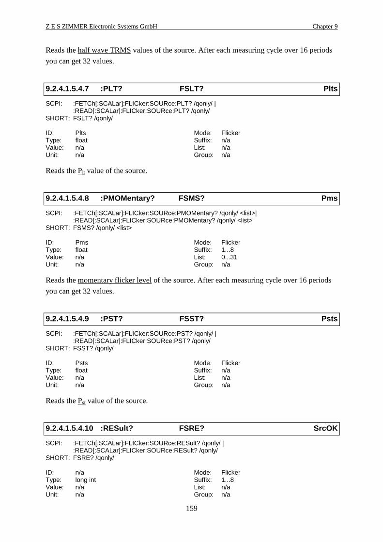
Z E S ZIMMER Electronic Systems GmbH Chapter 9
159
Reads the half wave TRMS values of the source. After each measuring cycle over 16 periods
you can get 32 values.
9.2.4.1.5.4.7 :PLT? FSLT? Plts
SCPI: :FETCh[:SCALar]:FLICker:SOURce:PLT? /qonly/ |:READ[:SCALar]:FLICker:SOURce:PLT? /qonly/
SHORT: FSLT? /qonly/
ID: Plts Mode: FlickerType: float Suffix: n/aValue: n/a List: n/aUnit: n/a Group: n/a
Reads the Plt value of the source.
9.2.4.1.5.4.8 :PMOMentary? FSMS? Pms
SCPI: :FETCh[:SCALar]:FLICker:SOURce:PMOMentary? /qonly/ <list>| :READ[:SCALar]:FLICker:SOURce:PMOMentary? /qonly/ <list>
SHORT: FSMS? /qonly/ <list>
ID: Pms Mode: FlickerType: float Suffix: 1...8Value: n/a List: 0...31Unit: n/a Group: n/a
Reads the momentary flicker level of the source. After each measuring cycle over 16 periods
you can get 32 values.
9.2.4.1.5.4.9 :PST? FSST? Psts
SCPI: :FETCh[:SCALar]:FLICker:SOURce:PST? /qonly/ |:READ[:SCALar]:FLICker:SOURce:PST? /qonly/
SHORT: FSST? /qonly/
ID: Psts Mode: FlickerType: float Suffix: n/aValue: n/a List: n/aUnit: n/a Group: n/a
Reads the Pst value of the source.
9.2.4.1.5.4.10 :RESult? FSRE? SrcOK
SCPI: :FETCh[:SCALar]:FLICker:SOURce:RESult? /qonly/ |:READ[:SCALar]:FLICker:SOURce:RESult? /qonly/
SHORT: FSRE? /qonly/
ID: n/a Mode: FlickerType: long int Suffix: 1...8Value: n/a List: n/aUnit: n/a Group: n/a
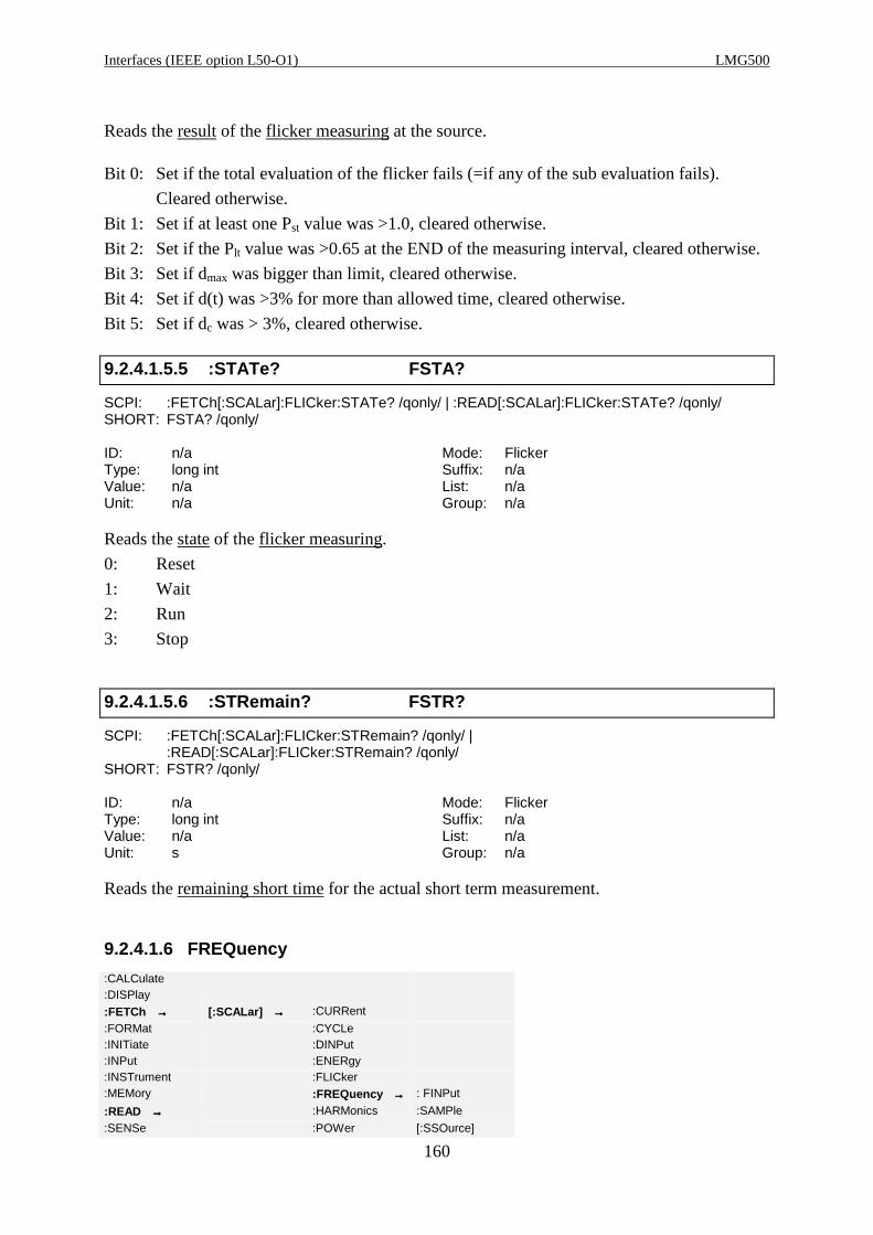
Interfaces (IEEE option L50-O1) LMG500
160
Reads the result of the flicker measuring at the source.
Bit 0: Set if the total evaluation of the flicker fails (=if any of the sub evaluation fails).
Cleared otherwise.
Bit 1: Set if at least one Pst value was >1.0, cleared otherwise.
Bit 2: Set if the Plt value was >0.65 at the END of the measuring interval, cleared otherwise.
Bit 3: Set if dmax was bigger than limit, cleared otherwise.
Bit 4: Set if d(t) was >3% for more than allowed time, cleared otherwise.
Bit 5: Set if dc was > 3%, cleared otherwise.
9.2.4.1.5.5 :STATe? FSTA?
SCPI: :FETCh[:SCALar]:FLICker:STATe? /qonly/ | :READ[:SCALar]:FLICker:STATe? /qonly/SHORT: FSTA? /qonly/
ID: n/a Mode: FlickerType: long int Suffix: n/aValue: n/a List: n/aUnit: n/a Group: n/a
Reads the state of the flicker measuring.
0: Reset
1: Wait
2: Run
3: Stop
9.2.4.1.5.6 :STRemain? FSTR?
SCPI: :FETCh[:SCALar]:FLICker:STRemain? /qonly/ |:READ[:SCALar]:FLICker:STRemain? /qonly/
SHORT: FSTR? /qonly/
ID: n/a Mode: FlickerType: long int Suffix: n/aValue: n/a List: n/aUnit: s Group: n/a
Reads the remaining short time for the actual short term measurement.
9.2.4.1.6 FREQuency
:CALCulate:DISPlay
:FETCh →→→→ [:SCALar] →→→→ :CURRent
:FORMat :CYCLe:INITiate :DINPut:INPut :ENERgy:INSTrument :FLICker:MEMory :FREQuency →→→→ : FINPut
:READ →→→→ :HARMonics :SAMPle
:SENSe :POWer [:SSOurce]

Z E S ZIMMER Electronic Systems GmbH Chapter 9
161
:SOURce :RESistance:STATus :SSYStem:SYSTem :VARiable:TRIGger [:VOLTage]
9.2.4.1.6.1 :FINPut? DIFQ? DigFrq
SCPI: :FETCh[:SCALar]:FREQuency:FINPut? /qonly/ |:READ[:SCALar]:FREQuency:FINPut? /qonly/
SHORT: DIFQ?/qonly/
ID: DigFrq Mode: AllType: float Suffix: 1, 2Value: n/a List: n/aUnit: Hz Group: n/a
Reads the value of frequency input of the processing signal interface.
9.2.4.1.6.2 :SAMPle? SMPL?
SCPI: :FETCh[:SCALar]:FREQuency:SAMPle? /qonly/ |:READ[:SCALar]:FREQuency:SAMPLe? /qonly/
SHORT: SMPL? /qonly/
ID: n/a Mode: AllType: float Suffix: n/aValue: n/a List: n/aUnit: Hz Group: optional [,<NRi>], 0=A, 1=B, ...
Reads the sampling frequency of the LMG.
9.2.4.1.6.3 :SSOurce? FREQ? f
SCPI: :FETCh[:SCALar]:FREQuency[:SSOurce]? /qonly/ | :READ[:SCALar]:FREQuency[:SSOurce]? /qonly/
SHORT: FREQ? /qonly/
ID: f Mode: AllType: float Suffix: 1...18Value: n/a List: n/aUnit: Hz Group: n/a
Reads the frequency of the synchronisation source
9.2.4.1.7 :HARMonics
:CALCulate:DISPlay
:FETCh →→→→ [:SCALar] →→→→ :CURRent
:FORMat :CYCLe:INITiate :DINPut:INPut :ENERgy:INSTrument :FLICker:MEMory :FREQuency
:READ →→→→ :HARMonics →→→→ :AMPFactor
:SENSe :POWer :AMPower

Interfaces (IEEE option L50-O1) LMG500
162
:SOURce :RESistance :APFactor:STATus :VARiable :APower:SYSTem [:VOLTage] :CDResult:TRIGger :CURRent
:LTRemain:POWer[:VOLTage]
9.2.4.1.7.1 :AMPFactor? HPFM?
SCPI: :FETCh[:SCALar]:HARMonics:AMPFactor? /qonly/ | :READ[:SCALar]:HARMonics:AMPFactor? /qonly/
SHORT: HPFM? /qonly/
ID: n/a Mode: CEType: float Suffix: 1...8Value: n/a List: n/aUnit: n/a Group: n/a
Reads the maximum smoothed power factor of the harmonic measuring.
9.2.4.1.7.2 :AMPower? HPM?
SCPI: :FETCh[:SCALar]:HARMonics:AMPower? /qonly/ | :READ[:SCALar]:HARMonics:AMPower? /qonly/
SHORT: HPM? /qonly/
ID: n/a Mode: CEType: float Suffix: 1...8Value: n/a List: n/aUnit: W Group: n/a
Reads the maximum smoothed power of the harmonic measuring.
9.2.4.1.7.3 :APFactor? HPFA?
SCPI: :FETCh[:SCALar]:HARMonics:APFactor? /qonly/ | :READ[:SCALar]:HARMonics:APFactor? /qonly/
SHORT: HPFA? /qonly/
ID: n/a Mode: CEType: float Suffix: 1...8Value: n/a List: n/aUnit: n/a Group: n/a
Reads the smoothed power factor of the harmonic measuring.
9.2.4.1.7.4 :APOWer? HPAV?
SCPI: :FETCh[:SCALar]:HARMonics:APOWer? /qonly/ | :READ[:SCALar]:HARMonics:APOWer? /qonly/
SHORT: HPAV? /qonly/
ID: n/a Mode: CEType: float Suffix: 1...8Value: n/a List: n/a

Z E S ZIMMER Electronic Systems GmbH Chapter 9
163
Unit: W Group: n/a
Reads the smoothed power of the harmonic measuring.
9.2.4.1.7.5 :CDResult? HENS?
SCPI: :FETCh[:SCALar]:HARMonics:CDResult? /qonly/ |:READ[:SCALar]:HARMonics:CDResult? /qonly/
SHORT: HENS? /qonly/
ID: n/a Mode: CEType: long int Suffix: 1...8Value: n/a List: n/aUnit: n/a Group: n/a
Reads the class D result of the harmonic measuring:
Bit 0: Set if the total class D evaluation failed (=if any of the sub evaluation failed). Cleared
otherwise.
Bit 1: Set if the current was for <95% of time under the positive special envelop, cleared
otherwise.
Bit 2: Set if the current was for <95% of time under the negative special envelop, cleared
otherwise.
Bit 3: Set if P>600W, cleared otherwise.
Bit 4: Set if the total class C evaluation failed (=if any of the sub evaluation failed). Cleared
otherwise.
Bit 5: Set if the 60° condition failed in first halfwave. Cleared otherwise.
Bit 6: Set if the 65° condition failed in first halfwave. Cleared otherwise.
Bit 7: Set if the 90° condition failed in first halfwave. Cleared otherwise.
Bit 8: Set if the peak value in first halfwave is negative. Cleared otherwise.
Bit 9: Set if the 60° condition failed in second halfwave. Cleared otherwise.
Bit 10: Set if the 65° condition failed in second halfwave. Cleared otherwise.
Bit 11: Set if the 90° condition failed in second halfwave. Cleared otherwise.
Bit 12: Set if the peak value in second halfwave is negative. Cleared otherwise.
9.2.4.1.7.6 :CURRent
:CALCulate:DISPlay
:FETCh →→→→ [:SCALar] →→→→ :CURRent
:FORMat :CYCLe:INITiate :DINPut:INPut :ENERgy:INSTrument :FLICker:MEMory :FREQuency
:READ →→→→ :HARMonics →→→→ :AMPower
:SENSe :POWer :APFactor:SOURce :RESistance :CDResult:STATus :SSYStem :CURRent →→→→ :AAMPlitude
:SYSTem :VARiable :LTRemain :AFUNdamental:TRIGger [:VOLTage] :POWer :AMPLitude
[:VOLTage] :FPRotz
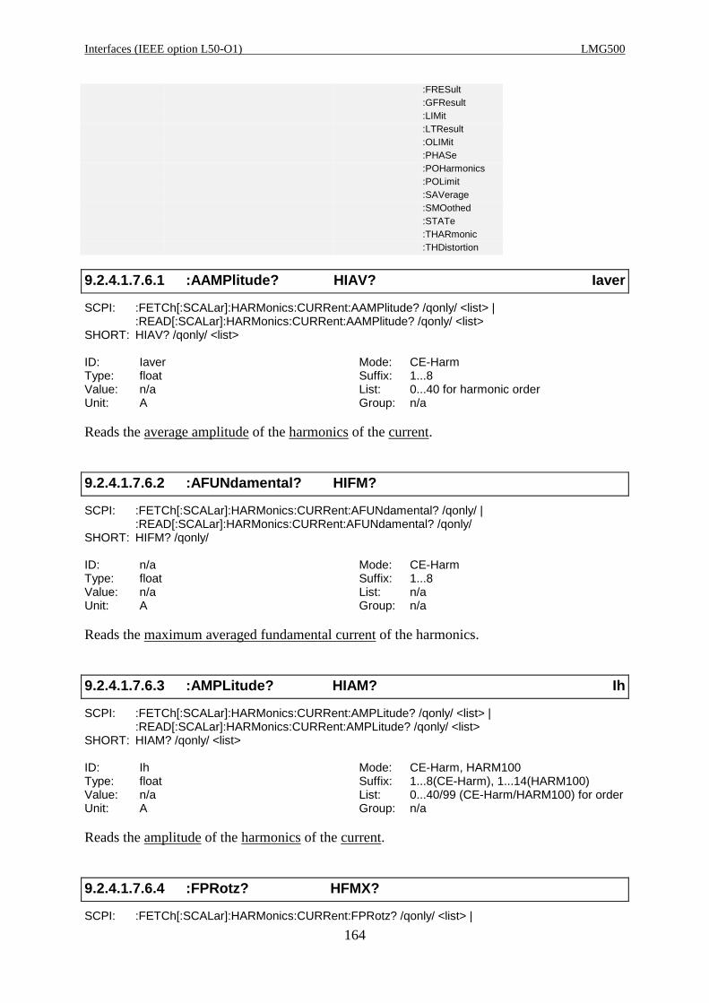
Interfaces (IEEE option L50-O1) LMG500
164
:FRESult:GFResult:LIMit:LTResult:OLIMit:PHASe:POHarmonics:POLimit:SAVerage:SMOothed:STATe:THARmonic:THDistortion
9.2.4.1.7.6.1 :AAMPlitude? HIAV? Iaver
SCPI: :FETCh[:SCALar]:HARMonics:CURRent:AAMPlitude? /qonly/ <list> | :READ[:SCALar]:HARMonics:CURRent:AAMPlitude? /qonly/ <list>
SHORT: HIAV? /qonly/ <list>
ID: Iaver Mode: CE-HarmType: float Suffix: 1...8Value: n/a List: 0...40 for harmonic orderUnit: A Group: n/a
Reads the average amplitude of the harmonics of the current.
9.2.4.1.7.6.2 :AFUNdamental? HIFM?
SCPI: :FETCh[:SCALar]:HARMonics:CURRent:AFUNdamental? /qonly/ |:READ[:SCALar]:HARMonics:CURRent:AFUNdamental? /qonly/
SHORT: HIFM? /qonly/
ID: n/a Mode: CE-HarmType: float Suffix: 1...8Value: n/a List: n/aUnit: A Group: n/a
Reads the maximum averaged fundamental current of the harmonics.
9.2.4.1.7.6.3 :AMPLitude? HIAM? Ih
SCPI: :FETCh[:SCALar]:HARMonics:CURRent:AMPLitude? /qonly/ <list> | :READ[:SCALar]:HARMonics:CURRent:AMPLitude? /qonly/ <list>
SHORT: HIAM? /qonly/ <list>
ID: Ih Mode: CE-Harm, HARM100Type: float Suffix: 1...8(CE-Harm), 1...14(HARM100)Value: n/a List: 0...40/99 (CE-Harm/HARM100) for orderUnit: A Group: n/a
Reads the amplitude of the harmonics of the current.
9.2.4.1.7.6.4 :FPRotz? HFMX?
SCPI: :FETCh[:SCALar]:HARMonics:CURRent:FPRotz? /qonly/ <list> |
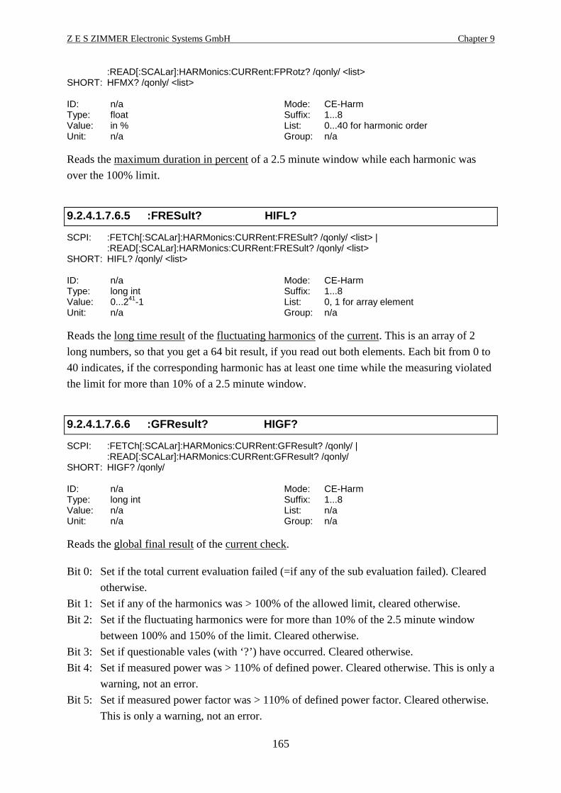
Z E S ZIMMER Electronic Systems GmbH Chapter 9
165
:READ[:SCALar]:HARMonics:CURRent:FPRotz? /qonly/ <list>SHORT: HFMX? /qonly/ <list>
ID: n/a Mode: CE-HarmType: float Suffix: 1...8Value: in % List: 0...40 for harmonic orderUnit: n/a Group: n/a
Reads the maximum duration in percent of a 2.5 minute window while each harmonic was
over the 100% limit.
9.2.4.1.7.6.5 :FRESult? HIFL?
SCPI: :FETCh[:SCALar]:HARMonics:CURRent:FRESult? /qonly/ <list> |:READ[:SCALar]:HARMonics:CURRent:FRESult? /qonly/ <list>
SHORT: HIFL? /qonly/ <list>
ID: n/a Mode: CE-HarmType: long int Suffix: 1...8Value: 0...241-1 List: 0, 1 for array elementUnit: n/a Group: n/a
Reads the long time result of the fluctuating harmonics of the current. This is an array of 2
long numbers, so that you get a 64 bit result, if you read out both elements. Each bit from 0 to
40 indicates, if the corresponding harmonic has at least one time while the measuring violated
the limit for more than 10% of a 2.5 minute window.
9.2.4.1.7.6.6 :GFResult? HIGF?
SCPI: :FETCh[:SCALar]:HARMonics:CURRent:GFResult? /qonly/ |:READ[:SCALar]:HARMonics:CURRent:GFResult? /qonly/
SHORT: HIGF? /qonly/
ID: n/a Mode: CE-HarmType: long int Suffix: 1...8Value: n/a List: n/aUnit: n/a Group: n/a
Reads the global final result of the current check.
Bit 0: Set if the total current evaluation failed (=if any of the sub evaluation failed). Cleared
otherwise.
Bit 1: Set if any of the harmonics was > 100% of the allowed limit, cleared otherwise.
Bit 2: Set if the fluctuating harmonics were for more than 10% of the 2.5 minute window
between 100% and 150% of the limit. Cleared otherwise.
Bit 3: Set if questionable vales (with ‘?’) have occurred. Cleared otherwise.
Bit 4: Set if measured power was > 110% of defined power. Cleared otherwise. This is only a
warning, not an error.
Bit 5: Set if measured power factor was > 110% of defined power factor. Cleared otherwise.
This is only a warning, not an error.
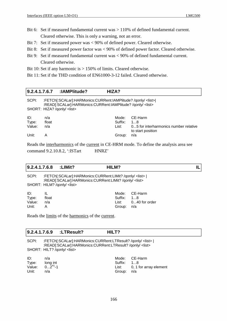
Interfaces (IEEE option L50-O1) LMG500
166
Bit 6: Set if measured fundamental current was > 110% of defined fundamental current.
Cleared otherwise. This is only a warning, not an error.
Bit 7: Set if measured power was < 90% of defined power. Cleared otherwise.
Bit 8: Set if measured power factor was < 90% of defined power factor. Cleared otherwise.
Bit 9: Set if measured fundamental current was < 90% of defined fundamental current.
Cleared otherwise.
Bit 10: Set if any harmonic is > 150% of limits. Cleared otherwise.
Bit 11: Set if the THD condition of EN61000-3-12 failed. Cleared otherwise.
9.2.4.1.7.6.7 :IAMPlitude? HIZA?
SCPI: :FETCh[:SCALar]:HARMonics:CURRent:IAMPlitude? /qonly/ <list>|:READ[:SCALar]:HARMonics:CURRent:IAMPlitude? /qonly/ <list>
SHORT: HIZA? /qonly/ <list>
ID: n/a Mode: CE-HarmType: float Suffix: 1...8Value: n/a List: 0...5 for interharmonics number relative
to start positionUnit: A Group: n/a
Reads the interharmonics of the current in CE-HRM mode. To define the analysis area see
command 9.2.10.8.2, ‘:ISTart HNRZ’
9.2.4.1.7.6.8 :LIMit? HILM? IL
SCPI: :FETCh[:SCALar]:HARMonics:CURRent:LIMit? /qonly/ <list> |:READ[:SCALar]:HARMonics:CURRent:LIMit? /qonly/ <list>
SHORT: HILM? /qonly/ <list>
ID: IL Mode: CE-HarmType: float Suffix: 1...8Value: n/a List: 0...40 for orderUnit: A Group: n/a
Reads the limits of the harmonics of the current.
9.2.4.1.7.6.9 :LTResult? HILT?
SCPI: :FETCh[:SCALar]:HARMonics:CURRent:LTResult? /qonly/ <list> |:READ[:SCALar]:HARMonics:CURRent:LTResult? /qonly/ <list>
SHORT: HILT? /qonly/ <list>
ID: n/a Mode: CE-HarmType: long int Suffix: 1...8Value: 0...241-1 List: 0, 1 for array elementUnit: n/a Group: n/a

Z E S ZIMMER Electronic Systems GmbH Chapter 9
167
Reads the long time result of the harmonics of the current. This is an array of 2 long numbers,
so that you get a 64 bit result, if you read out both elements. Each bit from 0 to 40 indicates, if
the corresponding harmonic has at least one time while the measuring violated the limit.
9.2.4.1.7.6.10 :OLIMit? HIOV?
SCPI: :FETCh[:SCALar]:HARMonics:CURRent:OLIMit? /qonly/ <list> |:READ[:SCALar]:HARMonics:CURRent:OLIMit? /qonly/ <list>
SHORT: HIOV? /qonly/ <list>
ID: n/a Mode: CE-HarmType: long int Suffix: 1...8Value: 0...241-1 List: 0...3 for array elementUnit: n/a Group: n/a
Reads the over limit status of the harmonics of the current. This is an array of 4 long numbers,
so that you get two 64 bit results, if you read out the elements 0/1 or 2/3.
For array element 2/3 each bit from 0 to 40 indicates, if the corresponding harmonic has
violated the limit in the actual frame (‘!’ on LMG display).
For array element 0/1 each bit from 0 to 40 indicates, if the corresponding harmonic has
violated the 100% limit but is within the 150% limit in the actual frame (‘?’ on LMG display).
9.2.4.1.7.6.11 :PHASe? HIPH? IP
SCPI: :FETCh[:SCALar]:HARMonics:CURRent:PHASe? /qonly/ <list> |:READ[:SCALar]:HARMonics:CURRent:PHASe? /qonly/ <list>
SHORT: HIPH? /qonly/ <list>
ID: IP Mode: HARM100Type: float Suffix: 1...14Value: n/a List: 0...99 for orderUnit: ° Group: n/a
Reads the phase of the harmonics of the current.
9.2.4.1.7.6.12 :POHarmonic? HPOC? Ipohc
SCPI: :FETCh[:SCALar]:HARMonics:CURRent:POHarmonic? /qonly/ | :READ[:SCALar]:HARMonics:CURRent:POHarmonic? /qonly/
SHORT: HPOC? /qonly/
ID: Ipohc Mode: CE-HarmType: float Suffix: 1...8Value: n/a List: n/aUnit: A Group: n/a
Reads the Partial Odd Harmonic Current.
9.2.4.1.7.6.13 :POLimit? HLIP?
SCPI: :FETCh[:SCALar]:HARMonics:CURRent:POLimit? /qonly/ |

Interfaces (IEEE option L50-O1) LMG500
168
:READ[:SCALar]:HARMonics:CURRent:POLimit? /qonly/SHORT: HLIP? /qonly/
ID: n/a Mode: CE-HarmType: float Suffix: 1...8Value: n/a List: n/aUnit: A Group: n/a
Reads the partial odd harmonic current which is calculated from the limits at the end of a
measuring.
9.2.4.1.7.6.14 :SAVerage? HIAS?
SCPI: :FETCh[:SCALar]:HARMonics:CURRent:SAVerage? /qonly/ | :READ[:SCALar]:HARMonics:CURRent:SAVerage? /qonly/
SHORT: HIAS? /qonly/
ID: n/a Mode: CE-HarmType: float Suffix: 1...8Value: n/a List: n/aUnit: A Group: n/a
Reads the smoothed averaged TRMS current.
9.2.4.1.7.6.15 :SMOothed? HIMA?
SCPI: :FETCh[:SCALar]:HARMonics:CURRent:SMOothed? /qonly/ |:READ[:SCALar]:HARMonics:CURRent:SMOothed? /qonly/
SHORT: HIMA? /qonly/
ID: n/a Mode: CE-HarmType: float Suffix: 1...8Value: n/a List: n/aUnit: A Group: n/a
Reads the smoothed TRMS current in this measuring mode.
9.2.4.1.7.6.16 :STATe? HIST?
SCPI: :FETCh[:SCALar]:HARMonics:CURRent:STATe? /qonly/ |:READ[:SCALar]:HARMonics:CURRent:STATe? /qonly/
SHORT: HIST? /qonly/
ID: n/a Mode: CE-HarmType: long int Suffix: 1...8Value: n/a List: n/aUnit: n/a Group: n/a
Reads the actual result of the current check:
Bit 0: Set if the total current evaluation failed (=if any of the sub evaluation failed). Cleared
otherwise.
Bit 1: Set if any of the harmonics was > 100% of the allowed limit, cleared otherwise.

Z E S ZIMMER Electronic Systems GmbH Chapter 9
169
Bit 2: Set if the fluctuating harmonics were for more than 10% of the 2.5 minute window
between 100% and 150% of the limit. Cleared otherwise.
Bit 3: Set if questionable vales (with ‘?’) have occurred. Cleared otherwise.
Bit 10: Set if any harmonic is > 150% of limits. Cleared otherwise.
9.2.4.1.7.6.17 :THARmonic? HTHC? Ithc
SCPI: :FETCh[:SCALar]:HARMonics:CURRent:THARmonic? /qonly/ |:READ[:SCALar]:HARMonics:CURRent:THARmonic? /qonly/
SHORT: HTHC? /qonly/
ID: Ithc Mode: CE-HarmType: float Suffix: 1...8Value: n/a List: n/aUnit: A Group: n/a
Reads the Total Harmonic Current.
9.2.4.1.7.6.18 :THDistort? HIHD? Ithd
SCPI: :FETCh[:SCALar]:HARMonics:CURRent:THDistort? /qonly/ |:READ[:SCALar]:HARMonics:CURRent:THDistort? /qonly/
SHORT: HIHD? /qonly/
ID: Ithd Mode: CE-Harm, Flicker, HARM100Type: float Suffix: 1...8/12Value: in % List: n/aUnit: n/a Group: n/a
Reads the THD of the current.
9.2.4.1.7.7 :LTRemain? HLTR?
SCPI: :FETCh[:SCALar]:HARMonics:LTRemain? /qonly/ |:READ[:SCALar]: HARMonics:LTRemain? /qonly/
SHORT: HLTR? /qonly/
ID: n/a Mode: CE-HarmType: long int Suffix: n/aValue: n/a List: n/aUnit: s Group: n/a
Reads the remaining long time for the harmonic measurement.
9.2.4.1.7.8 :POWer
:CALCulate:DISPlay
:FETCh →→→→ [:SCALar] →→→→ :CURRent
:FORMat :CYCLe:INITiate :DINPut:INPut :ENERgy:INSTrument :FLICker:MEMory :FREQuency
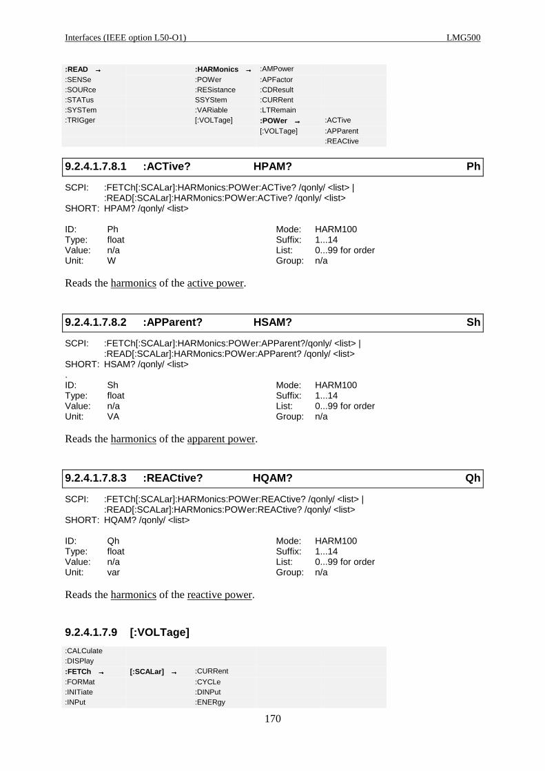
Interfaces (IEEE option L50-O1) LMG500
170
:READ →→→→ :HARMonics →→→→ :AMPower
:SENSe :POWer :APFactor:SOURce :RESistance :CDResult:STATus SSYStem :CURRent:SYSTem :VARiable :LTRemain:TRIGger [:VOLTage] :POWer →→→→ :ACTive
[:VOLTage] :APParent:REACtive
9.2.4.1.7.8.1 :ACTive? HPAM? Ph
SCPI: :FETCh[:SCALar]:HARMonics:POWer:ACTive? /qonly/ <list> |:READ[:SCALar]:HARMonics:POWer:ACTive? /qonly/ <list>
SHORT: HPAM? /qonly/ <list>
ID: Ph Mode: HARM100Type: float Suffix: 1...14Value: n/a List: 0...99 for orderUnit: W Group: n/a
Reads the harmonics of the active power.
9.2.4.1.7.8.2 :APParent? HSAM? Sh
SCPI: :FETCh[:SCALar]:HARMonics:POWer:APParent?/qonly/ <list> | :READ[:SCALar]:HARMonics:POWer:APParent? /qonly/ <list>
SHORT: HSAM? /qonly/ <list>.ID: Sh Mode: HARM100Type: float Suffix: 1...14Value: n/a List: 0...99 for orderUnit: VA Group: n/a
Reads the harmonics of the apparent power.
9.2.4.1.7.8.3 :REACtive? HQAM? Qh
SCPI: :FETCh[:SCALar]:HARMonics:POWer:REACtive? /qonly/ <list> | :READ[:SCALar]:HARMonics:POWer:REACtive? /qonly/ <list>
SHORT: HQAM? /qonly/ <list>
ID: Qh Mode: HARM100Type: float Suffix: 1...14Value: n/a List: 0...99 for orderUnit: var Group: n/a
Reads the harmonics of the reactive power.
9.2.4.1.7.9 [:VOLTage]
:CALCulate:DISPlay
:FETCh →→→→ [:SCALar] →→→→ :CURRent
:FORMat :CYCLe:INITiate :DINPut:INPut :ENERgy

Z E S ZIMMER Electronic Systems GmbH Chapter 9
171
:INSTrument :FLICker:MEMory :FREQuency
:READ →→→→ :HARMonics →→→→ :AMPower
:SENSe :POWer :APFactor:SOURce :RESistance :CDResult:STATus :SSYStem :CURRent:SYSTem :VARiable :LTRemain:TRIGger [:VOLTage] :Power
[:VOLTage] →→→→ :AMPLitude
:GFResult:LIMit:LTResult:MAMPlitude:OLIMit:PHASe:STATe:THDistortion
9.2.4.1.7.9.1 :AMPLitude? HUAM? Uh
SCPI: :FETCh[:SCALar]:HARMonics[:VOLTage]:AMPLitude? /qonly/ <list> |:READ[:SCALar]:HARMonics[:VOLTage]:AMPLitude? /qonly/ <list>
SHORT: HUAM? /qonly/ <list>
ID: Uh Mode: CE-Harm, HARM100Type: float Suffix: 1...8(CE-Harm), 1...14(HARM100)Value: n/a List: 0...40/99 (CE-Harm/HARM100) for orderUnit: V Group: n/a
Reads the amplitude of the harmonics of the voltage.
9.2.4.1.7.9.2 :GFResult? HUGF?
SCPI: :FETCh[:SCALar]:HARMonics[:VOLTage]:GFResult? /qonly/ | :READ[:SCALar]:HARMonics[:VOLTage]:GFResult? /qonly/
SHORT: HUGF? /qonly/
ID: n/a Mode: CE-HarmType: long int Suffix: 1...8Value: n/a List: n/aUnit: n/a Group: n/a
Reads the global final result of the voltage check.
Bit 0: Set if the total voltage evaluation failed (=if any of the sub evaluation failed). Cleared
otherwise.
Bit 1: Set if any of the harmonics was > 100% of the allowed limit, cleared otherwise.
Bit 2: Set if the voltage amplitude was not within the limit, cleared otherwise.
Bit 3: Set if the frequency was not within the limit, cleared otherwise.
Bit 4: Set if the crest factor was not within the limit, cleared otherwise.
Bit 5: Set, if the peak value is not within 90°±3°
9.2.4.1.7.9.3 :HWCFactor? FLCF?
SCPI: :FETCh[:SCALar]:HARMonics[:VOLTage]: HWCFactor? /qonly/ <list>|

Interfaces (IEEE option L50-O1) LMG500
172
:READ[:SCALar]:HARMonics[:VOLTage]: HWCFactor? /qonly/ <list>SHORT: FLCF? /qonly/ <list>
ID: n/a Mode: CE-HarmType: float Suffix: 1...8Value: n/a List: 0...31 for half wave numberUnit: n/a Group: n/a
Reads the voltage crest factor of the half waves. After each measuring cycle over 16 periods
you can get 32 values.
9.2.4.1.7.9.4 :IAMPlitude? HUZA?
SCPI: :FETCh[:SCALar]:HARMonics:VOLTage:IAMPlitude? /qonly/ | :READ[:SCALar]:HARMonics:VOLTage:IAMPlitude? /qonly/
SHORT: HUZA? /qonly/
ID: n/a Mode: CE-HarmType: float Suffix: 0...8Value: n/a List: 0...5 for interharmonics number relative
to start positionUnit: V Group: n/a
Reads the interharmonics of the voltage. To define the analysis area see command 9.2.10.8.2,
‘:ISTart HNRZ’
9.2.4.1.7.9.5 :LIMit? HULM? UL
SCPI: :FETCh[:SCALar]:HARMonics[:VOLTage]:LIMit? /qonly/ <list> | :READ[:SCALar]:HARMonics[:VOLTage]:LIMit? /qonly/ <list>
SHORT: HULM? /qonly/ <list>
ID: UL Mode: CE-HarmType: float Suffix: 1...8Value: n/a List: 0...40 for orderUnit: V Group: n/a
Reads the limits of the harmonics of the voltage.
9.2.4.1.7.9.6 :LTResult? HULT?
SCPI: :FETCh[:SCALar]:HARMonics[:VOLTage]:LTResult? /qonly/ <list> | :READ[:SCALar]:HARMonics[:VOLTage]:LTResult? /qonly/ <list>
SHORT: HULT? /qonly/ <list>
ID: n/a Mode: CE-HarmType: long int Suffix: 1...8Value: 0...241-1 List: 0, 1 for array elementUnit: n/a Group: n/a
Reads the long time result of the harmonics of the voltage. This is an array of 2 long numbers,
so that you get a 64 bit result, if you read out both elements. Each bit from 0 to 40 indicates, if
the corresponding harmonic has at least one time while the measuring violated the limit.
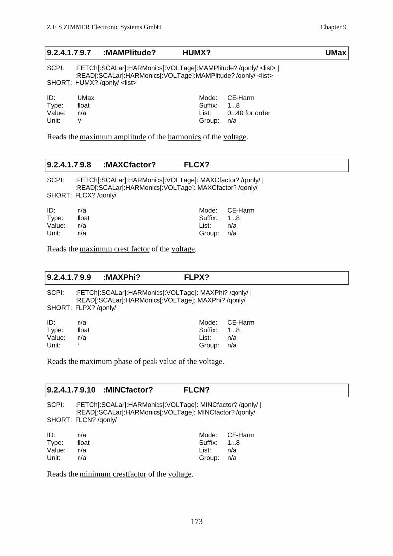
Z E S ZIMMER Electronic Systems GmbH Chapter 9
173
9.2.4.1.7.9.7 :MAMPlitude? HUMX? UMax
SCPI: :FETCh[:SCALar]:HARMonics[:VOLTage]:MAMPlitude? /qonly/ <list> | :READ[:SCALar]:HARMonics[:VOLTage]:MAMPlitude? /qonly/ <list>
SHORT: HUMX? /qonly/ <list>
ID: UMax Mode: CE-HarmType: float Suffix: 1...8Value: n/a List: 0...40 for orderUnit: V Group: n/a
Reads the maximum amplitude of the harmonics of the voltage.
9.2.4.1.7.9.8 :MAXCfactor? FLCX?
SCPI: :FETCh[:SCALar]:HARMonics[:VOLTage]: MAXCfactor? /qonly/ | :READ[:SCALar]:HARMonics[:VOLTage]: MAXCfactor? /qonly/
SHORT: FLCX? /qonly/
ID: n/a Mode: CE-HarmType: float Suffix: 1...8Value: n/a List: n/aUnit: n/a Group: n/a
Reads the maximum crest factor of the voltage.
9.2.4.1.7.9.9 :MAXPhi? FLPX?
SCPI: :FETCh[:SCALar]:HARMonics[:VOLTage]: MAXPhi? /qonly/ | :READ[:SCALar]:HARMonics[:VOLTage]: MAXPhi? /qonly/
SHORT: FLPX? /qonly/
ID: n/a Mode: CE-HarmType: float Suffix: 1...8Value: n/a List: n/aUnit: ° Group: n/a
Reads the maximum phase of peak value of the voltage.
9.2.4.1.7.9.10 :MINCfactor? FLCN?
SCPI: :FETCh[:SCALar]:HARMonics[:VOLTage]: MINCfactor? /qonly/ | :READ[:SCALar]:HARMonics[:VOLTage]: MINCfactor? /qonly/
SHORT: FLCN? /qonly/
ID: n/a Mode: CE-HarmType: float Suffix: 1...8Value: n/a List: n/aUnit: n/a Group: n/a
Reads the minimum crestfactor of the voltage.
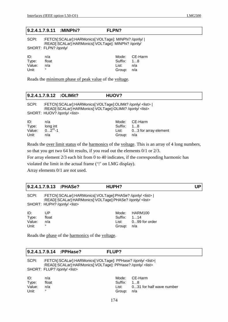
Interfaces (IEEE option L50-O1) LMG500
174
9.2.4.1.7.9.11 :MINPhi? FLPN?
SCPI: :FETCh[:SCALar]:HARMonics[:VOLTage]: MINPhi? /qonly/ | :READ[:SCALar]:HARMonics[:VOLTage]: MINPhi? /qonly/
SHORT: FLPN? /qonly/
ID: n/a Mode: CE-HarmType: float Suffix: 1...8Value: n/a List: n/aUnit: ° Group: n/a
Reads the minimum phase of peak value of the voltage.
9.2.4.1.7.9.12 :OLIMit? HUOV?
SCPI: :FETCh[:SCALar]:HARMonics[:VOLTage]:OLIMit? /qonly/ <list> | :READ[:SCALar]:HARMonics[:VOLTage]:OLIMit? /qonly/ <list>
SHORT: HUOV? /qonly/ <list>
ID: n/a Mode: CE-HarmType: long int Suffix: 1...8Value: 0...241-1 List: 0...3 for array elementUnit: n/a Group: n/a
Reads the over limit status of the harmonics of the voltage. This is an array of 4 long numbers,
so that you get two 64 bit results, if you read out the elements 0/1 or 2/3.
For array element 2/3 each bit from 0 to 40 indicates, if the corresponding harmonic has
violated the limit in the actual frame (‘!’ on LMG display).
Array elements 0/1 are not used.
9.2.4.1.7.9.13 :PHASe? HUPH? UP
SCPI: :FETCh[:SCALar]:HARMonics[:VOLTage]:PHASe? /qonly/ <list> | :READ[:SCALar]:HARMonics[:VOLTage]:PHASe? /qonly/ <list>
SHORT: HUPH? /qonly/ <list>
ID: UP Mode: HARM100Type: float Suffix: 1...14Value: n/a List: 0...99 for orderUnit: ° Group: n/a
Reads the phase of the harmonics of the voltage.
9.2.4.1.7.9.14 :PPHase? FLUP?
SCPI: :FETCh[:SCALar]:HARMonics[:VOLTage]: PPHase? /qonly/ <list>| :READ[:SCALar]:HARMonics[:VOLTage]: PPHase? /qonly/ <list>
SHORT: FLUP? /qonly/ <list>
ID: n/a Mode: CE-HarmType: float Suffix: 1...8Value: n/a List: 0...31 for half wave numberUnit: ° Group: n/a
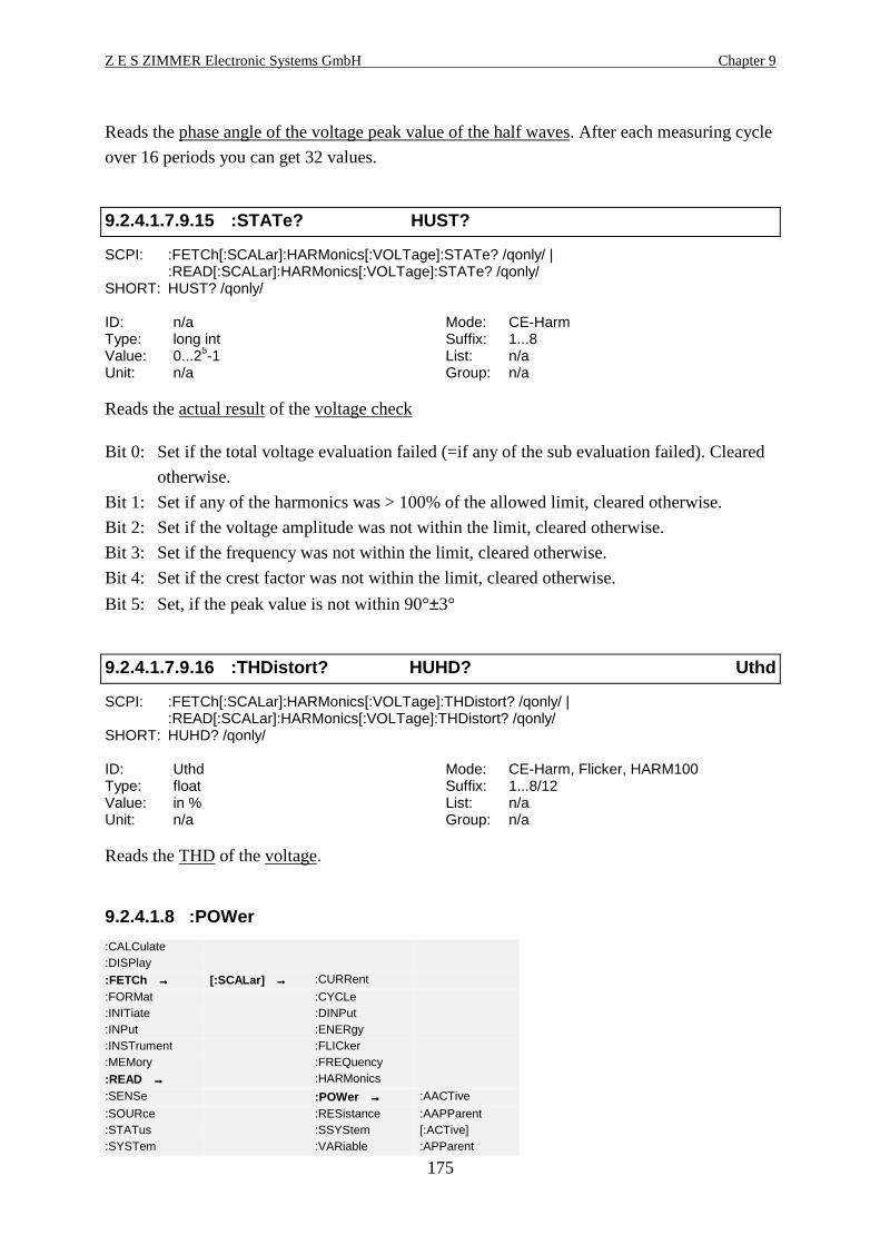
Z E S ZIMMER Electronic Systems GmbH Chapter 9
175
Reads the phase angle of the voltage peak value of the half waves. After each measuring cycle
over 16 periods you can get 32 values.
9.2.4.1.7.9.15 :STATe? HUST?
SCPI: :FETCh[:SCALar]:HARMonics[:VOLTage]:STATe? /qonly/ | :READ[:SCALar]:HARMonics[:VOLTage]:STATe? /qonly/
SHORT: HUST? /qonly/
ID: n/a Mode: CE-HarmType: long int Suffix: 1...8Value: 0...25-1 List: n/aUnit: n/a Group: n/a
Reads the actual result of the voltage check
Bit 0: Set if the total voltage evaluation failed (=if any of the sub evaluation failed). Cleared
otherwise.
Bit 1: Set if any of the harmonics was > 100% of the allowed limit, cleared otherwise.
Bit 2: Set if the voltage amplitude was not within the limit, cleared otherwise.
Bit 3: Set if the frequency was not within the limit, cleared otherwise.
Bit 4: Set if the crest factor was not within the limit, cleared otherwise.
Bit 5: Set, if the peak value is not within 90°±3°
9.2.4.1.7.9.16 :THDistort? HUHD? Uthd
SCPI: :FETCh[:SCALar]:HARMonics[:VOLTage]:THDistort? /qonly/ | :READ[:SCALar]:HARMonics[:VOLTage]:THDistort? /qonly/
SHORT: HUHD? /qonly/
ID: Uthd Mode: CE-Harm, Flicker, HARM100Type: float Suffix: 1...8/12Value: in % List: n/aUnit: n/a Group: n/a
Reads the THD of the voltage.
9.2.4.1.8 :POWer
:CALCulate:DISPlay
:FETCh →→→→ [:SCALar] →→→→ :CURRent
:FORMat :CYCLe:INITiate :DINPut:INPut :ENERgy:INSTrument :FLICker:MEMory :FREQuency
:READ →→→→ :HARMonics
:SENSe :POWer →→→→ :AACTive
:SOURce :RESistance :AAPParent:STATus :SSYStem [:ACTive]:SYSTem :VARiable :APParent

Interfaces (IEEE option L50-O1) LMG500
176
:TRIGger [:VOLTage] :AREactive:FSCale:ICAPacity:PFACtor:PHASe:REACtive
9.2.4.1.8.1 :AACTive? PM? Pm
SCPI: :FETCh[:SCALar]:POWer:AACTive? /qonly/ | :READ[:SCALar]:POWer:AACTive? /qonly/SHORT: PM? /qonly/
ID: Pm Mode: NormalType: float Suffix: 1...14Value: n/a List: n/aUnit: W Group: n/a
Reads the average active power of the energy measuring.
9.2.4.1.8.2 :AAPParent? SM? Sm
SCPI: :FETCh[:SCALar]:POWer:AAPParent? /qonly/ |:READ[:SCALar]:POWer:AAPParent? /qonly/
SHORT: SM? /qonly/
ID: Sm Mode: NormalType: float Suffix: 1...14Value: n/a List: n/aUnit: VA Group: n/a
Reads the average apparent power of the energy measuring.
9.2.4.1.8.3 [:ACTive]? P? P
SCPI: :FETCh[:SCALar]:POWer[:ACTive]? /qonly/ | :READ[:SCALar]:POWer[:ACTive]? /qonly/SHORT: P? /qonly/
ID: P Mode: AllType: float Suffix: 1...18Value: n/a List: n/aUnit: W Group: n/a
Reads the active power.
9.2.4.1.8.4 :APParent? S? S
SCPI: :FETCh[:SCALar]:POWer:APParent? /qonly/ | :READ[:SCALar]:POWer:APParent? /qonly/SHORT: S? /qonly/
ID: S Mode: AllType: float Suffix: 1...18Value: n/a List: n/aUnit: VA Group: n/a
Reads the apparent power.
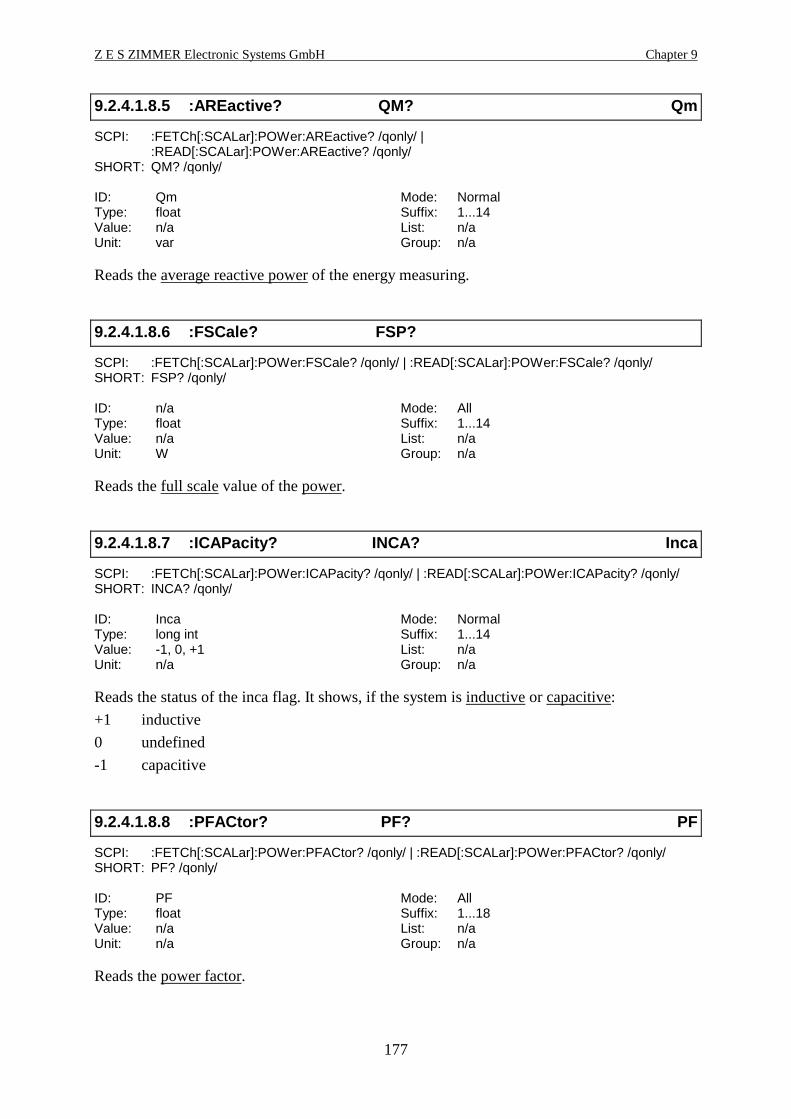
Z E S ZIMMER Electronic Systems GmbH Chapter 9
177
9.2.4.1.8.5 :AREactive? QM? Qm
SCPI: :FETCh[:SCALar]:POWer:AREactive? /qonly/ |:READ[:SCALar]:POWer:AREactive? /qonly/
SHORT: QM? /qonly/
ID: Qm Mode: NormalType: float Suffix: 1...14Value: n/a List: n/aUnit: var Group: n/a
Reads the average reactive power of the energy measuring.
9.2.4.1.8.6 :FSCale? FSP?
SCPI: :FETCh[:SCALar]:POWer:FSCale? /qonly/ | :READ[:SCALar]:POWer:FSCale? /qonly/SHORT: FSP? /qonly/
ID: n/a Mode: AllType: float Suffix: 1...14Value: n/a List: n/aUnit: W Group: n/a
Reads the full scale value of the power.
9.2.4.1.8.7 :ICAPacity? INCA? Inca
SCPI: :FETCh[:SCALar]:POWer:ICAPacity? /qonly/ | :READ[:SCALar]:POWer:ICAPacity? /qonly/SHORT: INCA? /qonly/
ID: Inca Mode: NormalType: long int Suffix: 1...14Value: -1, 0, +1 List: n/aUnit: n/a Group: n/a
Reads the status of the inca flag. It shows, if the system is inductive or capacitive:
+1 inductive
0 undefined
-1 capacitive
9.2.4.1.8.8 :PFACtor? PF? PF
SCPI: :FETCh[:SCALar]:POWer:PFACtor? /qonly/ | :READ[:SCALar]:POWer:PFACtor? /qonly/SHORT: PF? /qonly/
ID: PF Mode: AllType: float Suffix: 1...18Value: n/a List: n/aUnit: n/a Group: n/a
Reads the power factor.

Interfaces (IEEE option L50-O1) LMG500
178
9.2.4.1.8.9 :PHASe? PHI? PHI
SCPI: :FETCh[:SCALar]:POWer:PHASe? /qonly/ | :READ[:SCALar]:POWer:PHASe? /qonly/SHORT: PHI? /qonly/
ID: PHI Mode: NormalType: float Suffix: 1...14Value: n/a List: n/aUnit: ° Group: n/a
Reads the phase angle in degree between current and voltage.
9.2.4.1.8.10 :REACtive? Q? Q
SCPI: :FETCh[:SCALar]:POWer:REACtive? /qonly/ | :READ[:SCALar]:POWer:REACtive? /qonly/SHORT: Q? /qonly/
ID: Q Mode: AllType: float Suffix: 1...18Value: n/a List: n/aUnit: var Group: n/a
Reads the reactive power.
9.2.4.1.9 :RESistance
:CALCulate:DISPlay
:FETCh →→→→ [:SCALar] →→→→ :CURRent
:FORMat :CYCLe:INITiate :DINPut:INPut :ENERgy:INSTrument :FLICker:MEMory :FREQuency
:READ →→→→ :HARMonics
:SENSe :POWer:SOURce :RESistance →→→→ :ASResist
:STATus :SSYStem :IMPedance:SYSTem :VARiable :RSIMpedance:TRIGger [:VOLTage]
9.2.4.1.9.1 :ASResist? RSER? Rser
SCPI: :FETCh[:SCALar]:RESistance:ASResist? /qonly/ | :READ[:SCALar]:RESistance:ASResist? /qonly/
SHORT: RSER? /qonly/
ID: Rser Mode: Normal, CE-Harm, FlickerType: float Suffix: 1...14Value: n/a List: n/aUnit: Ω Group: n/a
Reads the active serial resistance.

Z E S ZIMMER Electronic Systems GmbH Chapter 9
179
9.2.4.1.9.2 :IMPedance? Z? Z
SCPI: :FETCh[:SCALar]:RESistance:IMPedance? /qonly/ | :READ[:SCALar]:RESistance:IMPedance? /qonly/
SHORT: Z? /qonly/
ID: Z Mode: Normal, CE-Harm, FlickerType: float Suffix: 1...14Value: n/a List: n/aUnit: Ω Group: n/a
Reads the impedance (apparent resistance).
9.2.4.1.9.3 :RSIMpedance? XSER? Xser
SCPI: :FETCh[:SCALar]:RESistance:RSIMpedance? /qonly/ | :READ[:SCALar]:RESistance:RSIMpedance? /qonly/
SHORT: XSER? /qonly/
ID: Xser Mode: Normal, CE-Harm, FlickerType: float Suffix: 1...14Value: n/a List: n/aUnit: Ω Group: n/a
Reads the reactive serial impedance.
9.2.4.1.10 :SSYStem? RLS?
SCPI: :FETCh[:SCALar]:SSYStem? /qonly/ [<NRi>] | :READ[:SCALar]:SSYStem? /qonly/ [<NRi>]SHORT: RLS? /qonly/
ID: n/a Mode: NormalType: long int Suffix: n/aValue: -1, 0, +1 List: n/aUnit: n/a Group: optional [<NRi>], 0=A, 1=B, ...
Reads the supply system:
0 undefined system
+1 right rotating system (phase order 1, 2, 3)
-1 left rotating system (phase order 3, 2, 1)
9.2.4.1.11 :STATe? TSTA?
SCPI: :FETCh[:SCALar]:TRANsient:STATe? /qonly/ | :READ[:SCALar]: TRANsient:STATe? /qonly/SHORT: TSTA? /qonly/
ID: n/a Mode: NormalType: long int Suffix: n/aValue: 0...2 List: n/aUnit: n/a Group: n/a
Reads the state of the transient search:
0 off

Interfaces (IEEE option L50-O1) LMG500
180
1 Search
2 found, fetching posttrigger
3 Finish
9.2.4.1.12 :VARiable? VAR?
SCPI: :FETCh[:SCALar]:VARiable? /qonly/ <list> | :READ[:SCALar]:VARiable? /qonly/ <list>SHORT: VAR? /qonly/ <list>
ID: The name a user has defined. Withscript ‘abc=Utrms*2;’ then ID would be‘abc’
Mode: All
Type: float Suffix: n/aValue: n/a List: 0...11 for array elementUnit: n/a Group: n/a
Reads value of the user defined variables. They are stored as an array.
9.2.4.1.13 :VNAMe? NVAR?
SCPI: :FETCh[:SCALar]:VNAMe? /qonly/ <string program data> | :READ[:SCALar]:VNAMe? /qonly/<string program data>SHORT: NVAR? /qonly/ <string program data>
ID: Mode: AllType: float Suffix: n/aValue: n/a List: n/aUnit: n/a Group: n/a
Reads the value of the user defined variable whose name was sent as <string program data>.
Example: You have a variable ‘abc’. This can be read by NVAR? „abc“.
9.2.4.1.14 [:VOLTage]
:CALCulate:DISPlay
:FETCh →→→→ [:SCALar] →→→→ :CURRent
:FORMat :CYCLe:INITiate :DINPut:INPut :ENERgy:INSTrument :FLICker:MEMory :FREQuency
:READ →→→→ :HARMonics
:SENSe :POWer:SOURce :RESistance:STATus :SSYStem:SYSTem :VARiable:TRIGger [:VOLTage] →→→→ :AC
:AINPut:CFACtor:DC:FFACtor:INRush:MAXPk:MINPk

Z E S ZIMMER Electronic Systems GmbH Chapter 9
181
:PPEak:RECTify:RUSed[:TRMS]
9.2.4.1.14.1 :AC? UAC? Uac
SCPI: :FETCh[:SCALar][:VOLTage]:AC? /qonly/ | :READ[:SCALar][:VOLTage]:AC? /qonly/SHORT: UAC? /qonly/
ID: Uac Mode: Normal, CE-HarmType: float Suffix: 1...14Value: n/a List: n/aUnit: V Group: n/a
Reads the AC value of the voltage.
9.2.4.1.14.2 :AINPut? AIVA? Ain
SCPI: :FETCh[:SCALar][:VOLTage]:AINPut? /qonly/ | :READ[:SCALar][:VOLTage]:AINPut? /qonly/SHORT: AIVA? /qonly/
ID: Ain Mode: AllType: float Suffix: 1...8Value: n/a List: n/aUnit: V Group: n/a
Reads the voltage of the analogue input of the processing signal interface.
9.2.4.1.14.3 :CFACtor? UCF? Ucf
SCPI: :FETCh[:SCALar][:VOLTage]:CFACtor? /qonly/ |:READ[:SCALar][:VOLTage]:CFACtor? /qonly/
SHORT: UCF? /qonly/
ID: Ucf Mode: NormalType: float Suffix: 1...14Value: n/a List: n/aUnit: n/a Group: n/a
Reads the crest factor of the voltage.
9.2.4.1.14.4 :DC? UDC? Udc
SCPI: :FETCh[:SCALar][:VOLTage]:DC? /qonly/ | :READ[:SCALar][:VOLTage]:DC? /qonly/SHORT: UDC? /qonly/
ID: Udc Mode: Normal, CE-HarmType: float Suffix: 1...14Value: n/a List: n/aUnit: V Group: n/a
Reads the DC value of the voltage.

Interfaces (IEEE option L50-O1) LMG500
182
9.2.4.1.14.5 :FFACtor? UFF? Uff
SCPI: :FETCh[:SCALar][:VOLTage]:FFACtor? /qonly/ |:READ[:SCALar][:VOLTage]:FFACtor? /qonly/
SHORT: UFF? /qonly/
ID: Uff Mode: NormalType: float Suffix: 1...14Value: n/a List: n/aUnit: n/a Group: n/a
Reads the form factor of the voltage.
9.2.4.1.14.6 :FSCale? FSU?
SCPI: :FETCh[:SCALar][:VOLTage]:FSCale? /qonly/ |:READ[:SCALar][:VOLTage]:FSCale? /qonly/
SHORT: FSU? /qonly/
ID: n/a Mode: AllType: float Suffix: 1...14Value: n/a List: n/aUnit: V Group: n/a
Reads the full scale value of the voltage.
9.2.4.1.14.7 :MAXPk? UMAX? Upkp
SCPI: :FETCh[:SCALar][:VOLTage]:MAXPk? /qonly/ |:READ[:SCALar][:VOLTage]:MAXPk? /qonly/
SHORT: UMAX? /qonly/
ID: Upkp Mode: NormalType: float Suffix: 1...14Value: n/a List: n/aUnit: V Group: n/a
Reads the biggest sample value of the voltage.
9.2.4.1.14.8 :MINPk? UMIN? Upkn
SCPI: :FETCh[:SCALar][:VOLTage]:MINPk? /qonly/ | :READ[:SCALar][:VOLTage]:MINPk? /qonly/SHORT: UMIN? /qonly/
ID: Upkn Mode: NormalType: float Suffix: 1...14Value: n/a List: n/aUnit: V Group: n/a
Reads the smallest sample value of the voltage.
9.2.4.1.14.9 :PHASe? UPHI? Uphi
SCPI: :FETCh[:SCALar][:VOLTage]:PHASe? /qonly/ | :READ[:SCALar][:VOLTage]:MINPk? /qonly/

Z E S ZIMMER Electronic Systems GmbH Chapter 9
183
SHORT: UPHI? /qonly/
ID: n/a Mode: NormalType: float Suffix: 1...14Value: n/a List: n/aUnit: ° Group: n/a
Reads the phase angle of the voltage like displayed in the Fresnel diagram.
9.2.4.1.14.10 :PPEak? UPP? Upp
SCPI: :FETCh[:SCALar][:VOLTage]:PPEak? /qonly/ | :READ[:SCALar][:VOLTage]:PPEak? /qonly/SHORT: UPP? /qonly/
ID: Upp Mode: NormalType: float Suffix: 1...14Value: n/a List: n/aUnit: V Group: n/a
Reads the peak peak value of the voltage.
9.2.4.1.14.11 :RECTify? UREC? Urect
SCPI: :FETCh[:SCALar][:VOLTage]:RECTify? /qonly/ |:READ[:SCALar][:VOLTage]:RECTify? /qonly/
SHORT: UREC? /qonly/
ID: Urect Mode: NormalType: float Suffix: 1...14Value: n/a List: n/aUnit: V Group: n/a
Reads the rectified value of the voltage.
9.2.4.1.14.12 :RUSed? OVRU? OvrU
SCPI: :FETCh[:SCALar][:VOLTage]:RUSed? /qonly/ |:READ[:SCALar][:VOLTage]:RUSed? /qonly/
SHORT: OVRU? /qonly/
ID: OvrU Mode: AllType: float Suffix: 1...14Value: in % List: n/aUnit: n/a Group: n/a
Reads the usage of the range in percent.
9.2.4.1.14.13 [:TRMS?] UTRMS? Utrms
SCPI: :FETCh[:SCALar][:VOLTage][:TRMS]? /qonly/ |:READ[:SCALar][:VOLTage][:TRMS]? /qonly/
SHORT: UTRMS? /qonly/
ID: Utrms Mode: All
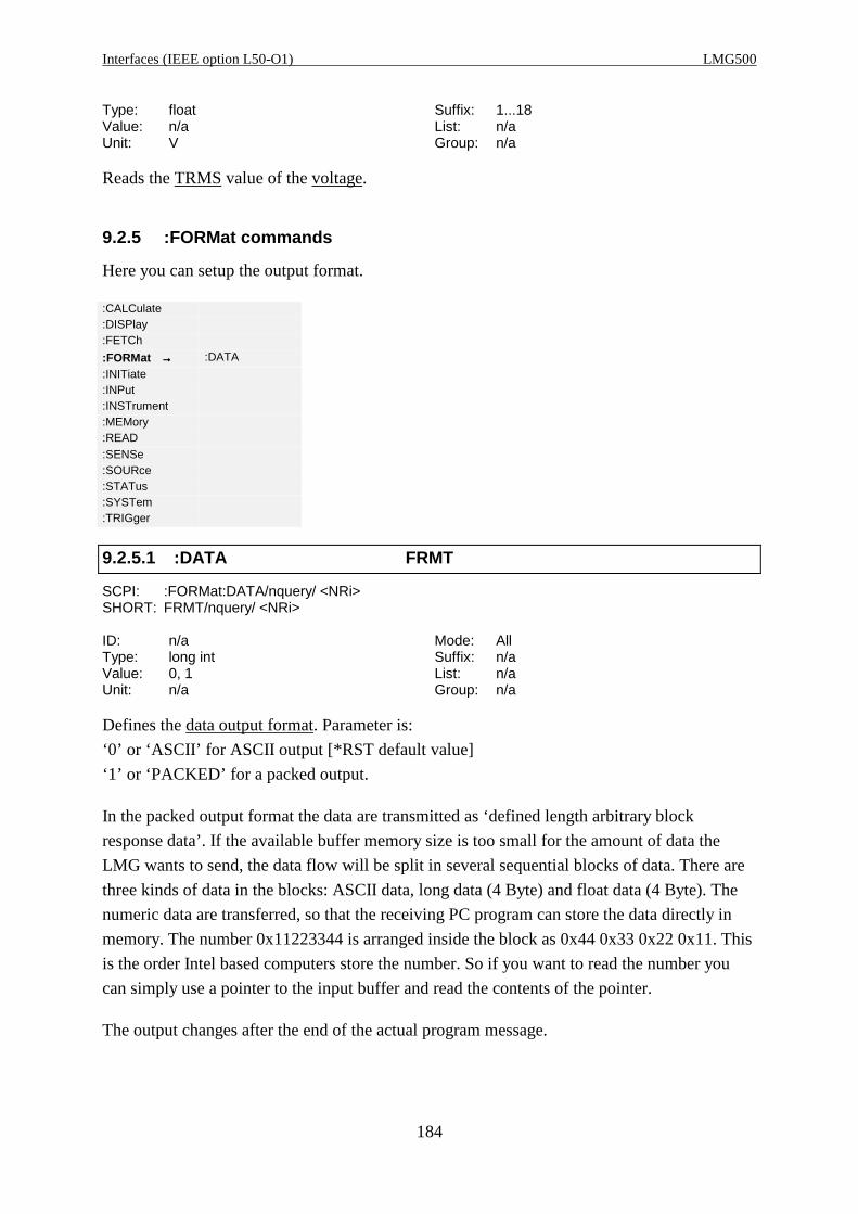
Interfaces (IEEE option L50-O1) LMG500
184
Type: float Suffix: 1...18Value: n/a List: n/aUnit: V Group: n/a
Reads the TRMS value of the voltage.
9.2.5 :FORMat commands
Here you can setup the output format.
:CALCulate:DISPlay:FETCh
:FORMat →→→→ :DATA
:INITiate:INPut:INSTrument:MEMory:READ:SENSe:SOURce:STATus:SYSTem:TRIGger
9.2.5.1 :DATA FRMT
SCPI: :FORMat:DATA/nquery/ <NRi>SHORT: FRMT/nquery/ <NRi>
ID: n/a Mode: AllType: long int Suffix: n/aValue: 0, 1 List: n/aUnit: n/a Group: n/a
Defines the data output format. Parameter is:
‘0’ or ‘ASCII’ for ASCII output [*RST default value]
‘1’ or ‘PACKED’ for a packed output.
In the packed output format the data are transmitted as ‘defined length arbitrary block
response data’. If the available buffer memory size is too small for the amount of data the
LMG wants to send, the data flow will be split in several sequential blocks of data. There are
three kinds of data in the blocks: ASCII data, long data (4 Byte) and float data (4 Byte). The
numeric data are transferred, so that the receiving PC program can store the data directly in
memory. The number 0x11223344 is arranged inside the block as 0x44 0x33 0x22 0x11. This
is the order Intel based computers store the number. So if you want to read the number you
can simply use a pointer to the input buffer and read the contents of the pointer.
The output changes after the end of the actual program message.

Z E S ZIMMER Electronic Systems GmbH Chapter 9
185
9.2.6 :INITiate commands
Here you can start or stop special actions.
:CALCulate:DISPlay:FETCh:FORMat
:INITiate →→→→ :CONTinuous
:INPut :COPY:INSTrument :IMMediate:MEMory:READ:SENSe:SOURce:STATus:SYSTem:TRIGger
9.2.6.1 :CONTinuous CONT
SCPI: :INITiate:CONTinuous <NRi>SHORT: CONT <NRi>
ID: n/a Mode: AllType: long int Suffix: n/aValue: 0, 1 List: n/aUnit: n/a Group: n/a
This activates or deactivates the continuous execution of the string defined with
:TRIGger:ACTion or ACTN. The programmer should only use :FETCh commands, because
when CONT is switched to ‘ON’, automatically an :INITiate:IMMediate is executed at the
end of each cycle.
Parameter:
‘ON’ or ‘1’ activates this mode
‘OFF’ or ‘0’ deactivates this mode [*RST default value]
The standard defines, that instruments with sequential commands can only exit the ‘ON’ state
by the device clear command of the interface. This works also with this instrument. But
additionally you can exit the ‘ON’ state by setting it to ‘OFF’ with :INITiate:CONTinuouse or
CONT.
9.2.6.2 :COPY COPY
SCPI: :INITiate:COPY/nquery/SHORT: COPY/nquery/
ID: n/a Mode: AllType: n/a Suffix: n/aValue: n/a List: n/aUnit: n/a Group: n/a
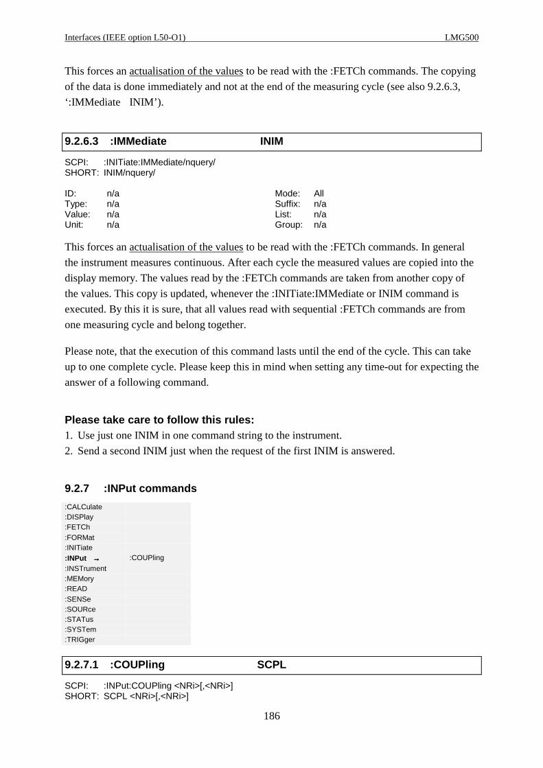
Interfaces (IEEE option L50-O1) LMG500
186
This forces an actualisation of the values to be read with the :FETCh commands. The copying
of the data is done immediately and not at the end of the measuring cycle (see also 9.2.6.3,
‘:IMMediate INIM’).
9.2.6.3 :IMMediate INIM
SCPI: :INITiate:IMMediate/nquery/SHORT: INIM/nquery/
ID: n/a Mode: AllType: n/a Suffix: n/aValue: n/a List: n/aUnit: n/a Group: n/a
This forces an actualisation of the values to be read with the :FETCh commands. In general
the instrument measures continuous. After each cycle the measured values are copied into the
display memory. The values read by the :FETCh commands are taken from another copy of
the values. This copy is updated, whenever the :INITiate:IMMediate or INIM command is
executed. By this it is sure, that all values read with sequential :FETCh commands are from
one measuring cycle and belong together.
Please note, that the execution of this command lasts until the end of the cycle. This can take
up to one complete cycle. Please keep this in mind when setting any time-out for expecting the
answer of a following command.
Please take care to follow this rules:1. Use just one INIM in one command string to the instrument.
2. Send a second INIM just when the request of the first INIM is answered.
9.2.7 :INPut commands
:CALCulate:DISPlay:FETCh:FORMat:INITiate
:INPut →→→→ :COUPling
:INSTrument:MEMory:READ:SENSe:SOURce:STATus:SYSTem:TRIGger
9.2.7.1 :COUPling SCPL
SCPI: :INPut:COUPling <NRi>[,<NRi>]SHORT: SCPL <NRi>[,<NRi>]
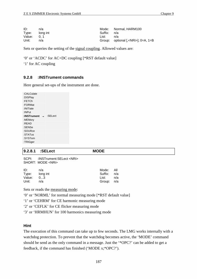
Z E S ZIMMER Electronic Systems GmbH Chapter 9
187
ID: n/a Mode: Normal, HARM100Type: long int Suffix: n/aValue: 0, 1 List: n/aUnit: n/a Group: optional [,<NRi>]; 0=A, 1=B
Sets or queries the setting of the signal coupling. Allowed values are:
‘0’ or ‘ACDC’ for AC+DC coupling [*RST default value]
‘1’ for AC coupling
9.2.8 :INSTrument commands
Here general set-ups of the instrument are done.
:CALCulate:DISPlay:FETCh:FORMat:INITiate:INPut
:INSTrument →→→→ :SELect
:MEMory:READ:SENSe:SOURce:STATus:SYSTem:TRIGger
9.2.8.1 :SELect MODE
SCPI: :INSTrument:SELect <NRi>SHORT: MODE <NRi>
ID: n/a Mode: AllType: long int Suffix: n/aValue: 0...3 List: n/aUnit: n/a Group: n/a
Sets or reads the measuring mode:
‘0’ or ‘NORML’ for normal measuring mode [*RST default value]
‘1’ or ‘CEHRM’ for CE harmonic measuring mode
‘2’ or ‘CEFLK’ for CE flicker measuring mode
‘3’ or ‘HRMHUN’ for 100 harmonics measuring mode
HintThe execution of this command can take up to few seconds. The LMG works internally with a
watchdog protection. To prevent that the watchdog becomes active, the ‘MODE’ command
should be send as the only command in a message. Just the ‘*OPC?’ can be added to get a
feedback, if the command has finished (‘MODE x;*OPC?’).
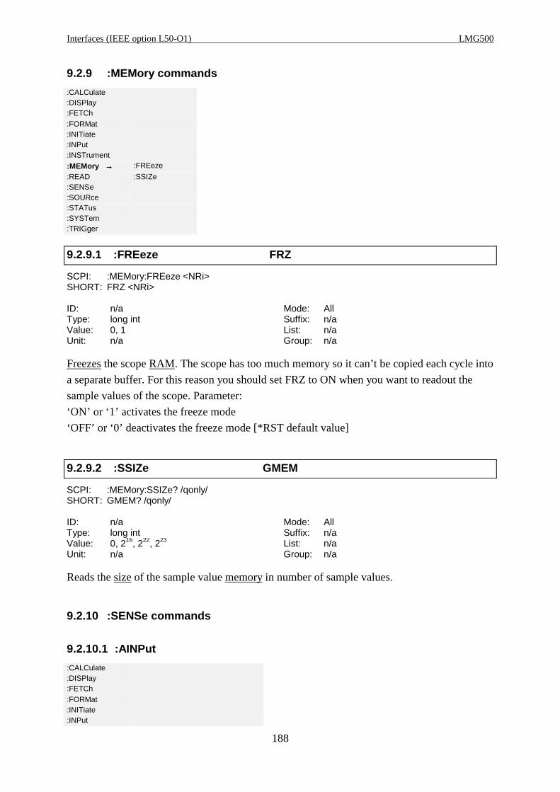
Interfaces (IEEE option L50-O1) LMG500
188
9.2.9 :MEMory commands
:CALCulate:DISPlay:FETCh:FORMat:INITiate:INPut:INSTrument
:MEMory →→→→ :FREeze
:READ :SSIZe:SENSe:SOURce:STATus:SYSTem:TRIGger
9.2.9.1 :FREeze FRZ
SCPI: :MEMory:FREeze <NRi>SHORT: FRZ <NRi>
ID: n/a Mode: AllType: long int Suffix: n/aValue: 0, 1 List: n/aUnit: n/a Group: n/a
Freezes the scope RAM. The scope has too much memory so it can’t be copied each cycle into
a separate buffer. For this reason you should set FRZ to ON when you want to readout the
sample values of the scope. Parameter:
‘ON’ or ‘1’ activates the freeze mode
‘OFF’ or ‘0’ deactivates the freeze mode [*RST default value]
9.2.9.2 :SSIZe GMEM
SCPI: :MEMory:SSIZe? /qonly/SHORT: GMEM? /qonly/
ID: n/a Mode: AllType: long int Suffix: n/aValue: 0, 216, 222, 223 List: n/aUnit: n/a Group: n/a
Reads the size of the sample value memory in number of sample values.
9.2.10 :SENSe commands
9.2.10.1 :AINPut
:CALCulate:DISPlay:FETCh:FORMat:INITiate:INPut
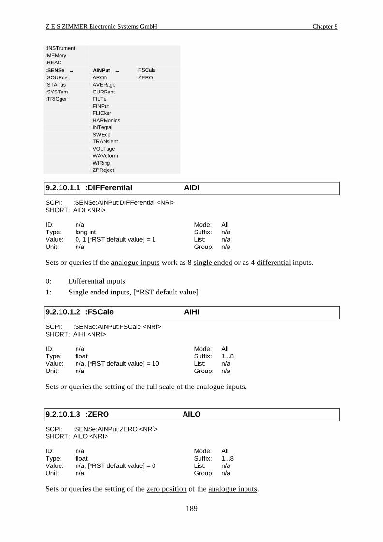
Z E S ZIMMER Electronic Systems GmbH Chapter 9
189
:INSTrument:MEMory:READ
:SENSe →→→→ :AINPut →→→→ :FSCale
:SOURce :ARON :ZERO:STATus :AVERage:SYSTem :CURRent:TRIGger :FILTer
:FINPut:FLICker:HARMonics:INTegral:SWEep:TRANsient:VOLTage:WAVeform:WIRing:ZPReject
9.2.10.1.1 :DIFFerential AIDI
SCPI: :SENSe:AINPut:DIFFerential <NRi>SHORT: AIDI <NRi>
ID: n/a Mode: AllType: long int Suffix: n/aValue: 0, 1 [*RST default value] = 1 List: n/aUnit: n/a Group: n/a
Sets or queries if the analogue inputs work as 8 single ended or as 4 differential inputs.
0: Differential inputs
1: Single ended inputs, [*RST default value]
9.2.10.1.2 :FSCale AIHI
SCPI: :SENSe:AINPut:FSCale <NRf>SHORT: AIHI <NRf>
ID: n/a Mode: AllType: float Suffix: 1...8Value: n/a, [*RST default value] = 10 List: n/aUnit: n/a Group: n/a
Sets or queries the setting of the full scale of the analogue inputs.
9.2.10.1.3 :ZERO AILO
SCPI: :SENSe:AINPut:ZERO <NRf>SHORT: AILO <NRf>
ID: n/a Mode: AllType: float Suffix: 1...8Value: n/a, [*RST default value] = 0 List: n/aUnit: n/a Group: n/a
Sets or queries the setting of the zero position of the analogue inputs.
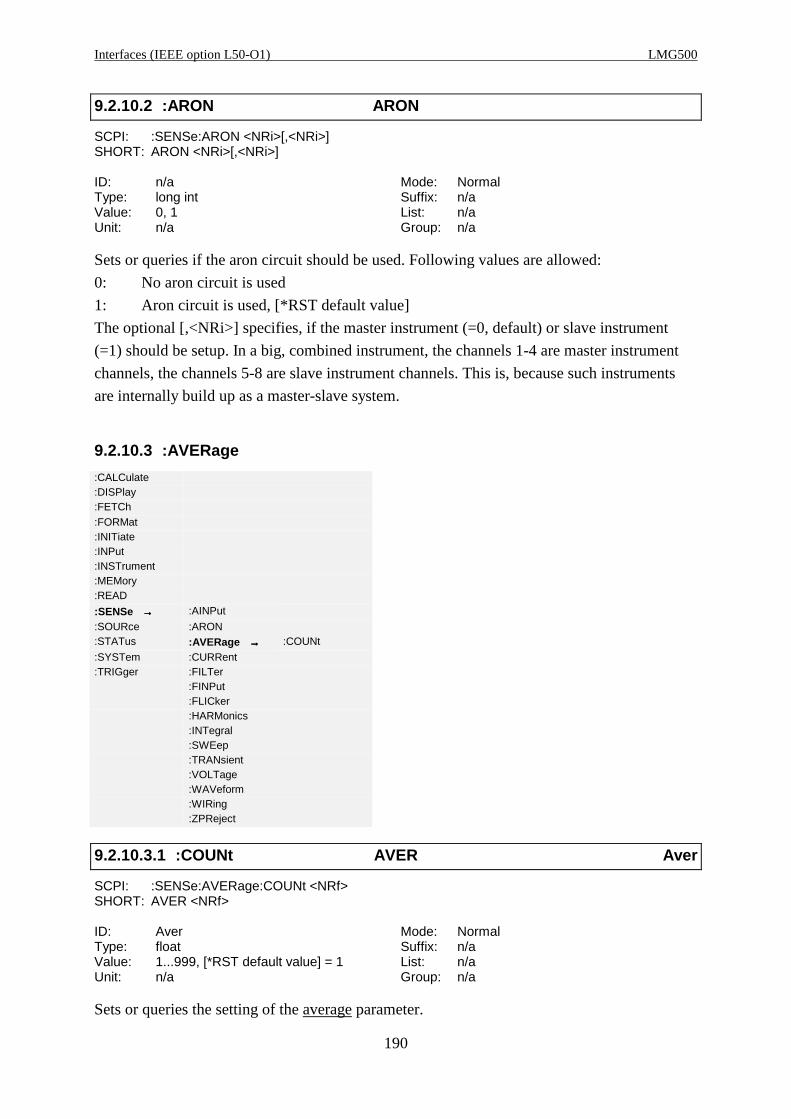
Interfaces (IEEE option L50-O1) LMG500
190
9.2.10.2 :ARON ARON
SCPI: :SENSe:ARON <NRi>[,<NRi>]SHORT: ARON <NRi>[,<NRi>]
ID: n/a Mode: NormalType: long int Suffix: n/aValue: 0, 1 List: n/aUnit: n/a Group: n/a
Sets or queries if the aron circuit should be used. Following values are allowed:
0: No aron circuit is used
1: Aron circuit is used, [*RST default value]
The optional [,<NRi>] specifies, if the master instrument (=0, default) or slave instrument
(=1) should be setup. In a big, combined instrument, the channels 1-4 are master instrument
channels, the channels 5-8 are slave instrument channels. This is, because such instruments
are internally build up as a master-slave system.
9.2.10.3 :AVERage
:CALCulate:DISPlay:FETCh:FORMat:INITiate:INPut:INSTrument:MEMory:READ
:SENSe →→→→ :AINPut
:SOURce :ARON:STATus :AVERage →→→→ :COUNt
:SYSTem :CURRent:TRIGger :FILTer
:FINPut:FLICker:HARMonics:INTegral:SWEep:TRANsient:VOLTage:WAVeform:WIRing:ZPReject
9.2.10.3.1 :COUNt AVER Aver
SCPI: :SENSe:AVERage:COUNt <NRf>SHORT: AVER <NRf>
ID: Aver Mode: NormalType: float Suffix: n/aValue: 1...999, [*RST default value] = 1 List: n/aUnit: n/a Group: n/a
Sets or queries the setting of the average parameter.

Z E S ZIMMER Electronic Systems GmbH Chapter 9
191
9.2.10.4 :CURRent
:CALCulate:DISPlay:FETCh:FORMat:INITiate:INPut:INSTrument:MEMory:READ
:SENSe →→→→ :AINPut
:SOURce :ARON:STATus :AVERage:SYSTem :CURRent →→→→ :DETector
:TRIGger :FILTer :IDENtify:FINPut :RANGe:FLICker :SCALe:HARMonics:INTegral:SWEep:TRANsient:VOLTage:WAVeform:WIRing:ZPReject
9.2.10.4.1 :DELay IDLY
SCPI: :SENSe:CURRent:DELay <NRi>SHORT: IDLY <NRi>
ID: n/a Mode: AllType: long int Suffix: 1...8Value: -2666...+2666, [*RST default value] = 0 List: n/aUnit: ns Group: n/a
Reads and sets the delay of the current input in ns. Positive values symbolize a delay, negative
values a negative delay!
Example: You have a current sensor with a group delay of +100ns. If you want to correct this
group delay, you have to set the current delay to -100ns.
9.2.10.4.2 :DETector IEXT
SCPI: :SENSe:CURRent:DETector <NRi>SHORT: IEXT <NRi>
ID: n/a Mode: AllType: long int Suffix: 1...8Value: 0...2 List: n/aUnit: n/a Group: n/a
Reads and sets internal or external shunt input:
‘0’ or ‘INT’ for internal shunt at I* jack (current input) [*RST default value]
‘1’ or ‘EXT’ for external shunt input (voltage input, sensor input)
‘2’ for for internal shunt at IHF jack (current input)
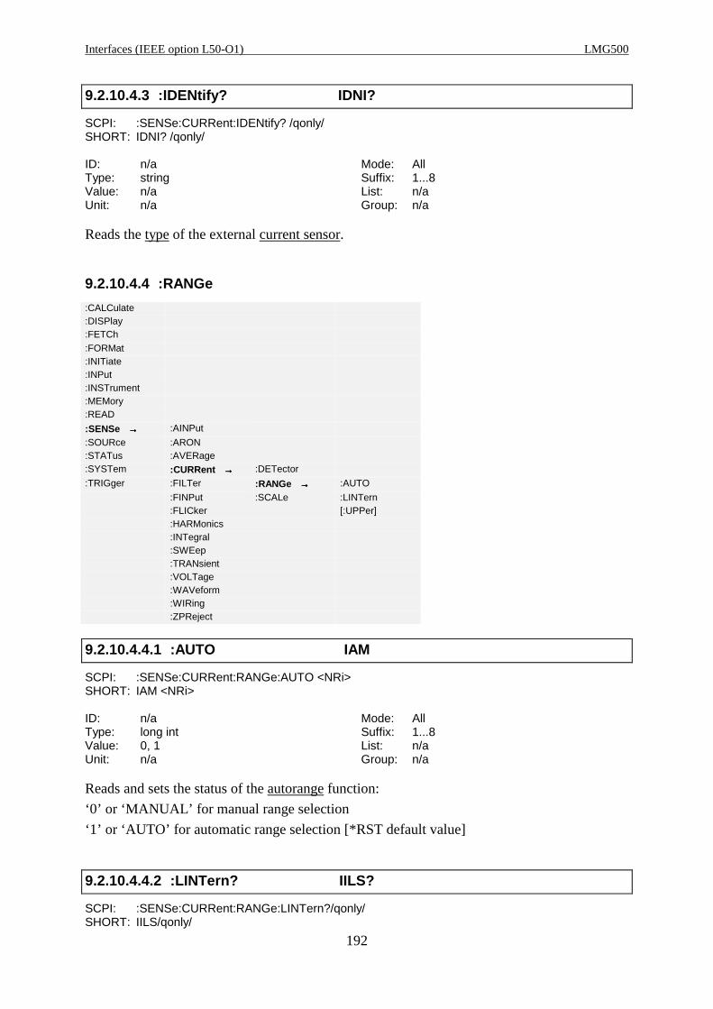
Interfaces (IEEE option L50-O1) LMG500
192
9.2.10.4.3 :IDENtify? IDNI?
SCPI: :SENSe:CURRent:IDENtify? /qonly/SHORT: IDNI? /qonly/
ID: n/a Mode: AllType: string Suffix: 1...8Value: n/a List: n/aUnit: n/a Group: n/a
Reads the type of the external current sensor.
9.2.10.4.4 :RANGe
:CALCulate:DISPlay:FETCh:FORMat:INITiate:INPut:INSTrument:MEMory:READ
:SENSe →→→→ :AINPut
:SOURce :ARON:STATus :AVERage:SYSTem :CURRent →→→→ :DETector
:TRIGger :FILTer :RANGe →→→→ :AUTO
:FINPut :SCALe :LINTern:FLICker [:UPPer]:HARMonics:INTegral:SWEep:TRANsient:VOLTage:WAVeform:WIRing:ZPReject
9.2.10.4.4.1 :AUTO IAM
SCPI: :SENSe:CURRent:RANGe:AUTO <NRi>SHORT: IAM <NRi>
ID: n/a Mode: AllType: long int Suffix: 1...8Value: 0, 1 List: n/aUnit: n/a Group: n/a
Reads and sets the status of the autorange function:
‘0’ or ‘MANUAL’ for manual range selection
‘1’ or ‘AUTO’ for automatic range selection [*RST default value]
9.2.10.4.4.2 :LINTern? IILS?
SCPI: :SENSe:CURRent:RANGe:LINTern?/qonly/SHORT: IILS/qonly/

Z E S ZIMMER Electronic Systems GmbH Chapter 9
193
ID: n/a Mode: AllType: float Suffix: 1...8Value: n/a List: n/aUnit: A Group: n/a
Reads a list with the available ranges. You get several numbers which are separated by colons
‘,’. The first number defines the number of following numbers. If you have selected external
sensors, you get the list of their ranges.
9.2.10.4.4.3 [:UPPer] IRNG RngI
SCPI: :SENSe:CURRent:RANGe[:UPPer] <NRf>SHORT: IRNG <NRf>
ID: RngI Mode: AllType: float Suffix: 1...8Value: n/a List: n/aUnit: A Group: n/a
Reads and sets the range for the current measurement. The parameter is the nominal value of
the range.
9.2.10.4.5 :SCALe ISCA Iscal
SCPI: :SENSe:CURRent:SCALe <NRf>SHORT: ISCA <NRf>
ID: Iscal Mode: AllType: float Suffix: 1...8Value: n/a, [*RST default value] = 1.0 List: n/aUnit: n/a Group: n/a
Reads and sets the scaling of the current range.
9.2.10.5 :FILTer
9.2.10.5.1 :AFILter FAAF
SCPI: :SENSe:FILTer:AFILter <NRi>[,<NRi>]SHORT: FAAF <NRi>[,<NRi>]
ID: n/a Mode: HARM100Type: long int Suffix: n/aValue: 0, 1 List: n/aUnit: n/a Group: optional [,<NRi>]; 0=A, 1=B, ...
Reads and sets the anti-aliasing-filter settings:
0: Anti aliasing filter manual setable (via FILT)
1: Anti aliasing filter selection automaticaly [*RST default value]

Interfaces (IEEE option L50-O1) LMG500
194
9.2.10.5.2 [:LPASs]
:CALCulate:DISPlay:FETCh:FORMat:INITiate:INPut:INSTrument:MEMory:READ
:SENSe →→→→ :AINPut
:SOURce :ARON:STATus :AVERage:SYSTem :CURRent:TRIGger :FILTer →→→→ [:LPASs] →→→→ [:STATe]
:FINPut:FLICker:HARMonics:INTegral:SWEep:TRANsient:VOLTage:WAVeform:WIRing:ZPReject
9.2.10.5.2.1 [:STATe] FILT
SCPI: :SENSe:FILTer[:LPASS][:STATe] <NRi>[,<NRi>]SHORT: FILT <NRi>[,<NRi>]
ID: n/a Mode: NormalType: long int Suffix: n/aValue: n/a List: n/aUnit: n/a Group: optional [,<NRi>]; 0=A, 1=B, ...
Reads and sets the filter settings:
0: Filter off [*RST default value]
1: Low pass 270kHz
2: Low pass 150kHz
3: Low pass 138kHz
4: Low pass 90kHz
5: Low pass 42kHz
6: Low pass 30kHz
7: Low pass 21kHz
9: Low pass 11kHz
10: Low pass 10kHz
11: Low pass 9.2kHz
12: Low pass 6kHz
14: Low pass 2.8kHz
16: Low pass 2kHz
17: Low pass 1.4kHz
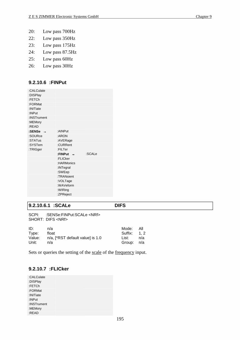
Z E S ZIMMER Electronic Systems GmbH Chapter 9
195
20: Low pass 700Hz
22: Low pass 350Hz
23: Low pass 175Hz
24: Low pass 87.5Hz
25: Low pass 60Hz
26: Low pass 30Hz
9.2.10.6 :FINPut
:CALCulate:DISPlay:FETCh:FORMat:INITiate:INPut:INSTrument:MEMory:READ
:SENSe →→→→ :AINPut
:SOURce :ARON:STATus :AVERage:SYSTem :CURRent:TRIGger :FILTer
:FINPut →→→→ :SCALe
:FLICker:HARMonics:INTegral:SWEep:TRANsient:VOLTage:WAVeform:WIRing:ZPReject
9.2.10.6.1 :SCALe DIFS
SCPI: :SENSe:FINPut:SCALe <NRf>SHORT: DIFS <NRf>
ID: n/a Mode: AllType: float Suffix: 1, 2Value: n/a, [*RST default value] is 1.0 List: n/aUnit: n/a Group: n/a
Sets or queries the setting of the scale of the frequency input.
9.2.10.7 :FLICker
:CALCulate:DISPlay:FETCh:FORMat:INITiate:INPut:INSTrument:MEMory:READ

Interfaces (IEEE option L50-O1) LMG500
196
:SENSe →→→→ :AINPut
:SOURce :ARON:STATus :AVERage:SYSTem :CURRent:TRIGger :FILTer
:FINPut
:FLICker →→→→ :PERiods
:HARMonics :STIMe:INTegral:SWEep:TRANsient:VOLTage:WAVeform:WIRing:ZPReject
9.2.10.7.1 :PERiods FLPS FlkPer
SCPI: :SENSe:FLICker:PERiods <NRf>SHORT: FLPS <NRf>
ID: FlkPer Mode: FlickerType: float Suffix: n/aValue: n/a, [*RST default value] = 12 List: n/aUnit: n/a Group: n/a
Reads and sets the number of periods for flicker measuring.
9.2.10.7.2 :STIMe FTIM
SCPI: :SENSe:FLICker:STIMe <NRi>SHORT: FTIM <NRi>
ID: n/a Mode: FlickerType: long int Suffix: n/aValue: n/a, [*RST default value] = 600 List: n/aUnit: s Group: n/a
Reads and sets the short term flicker measuring time.
9.2.10.8 :HARMonics
:CALCulate:DISPlay:FETCh:FORMat:INITiate:INPut:INSTrument:MEMory:READ
:SENSe →→→→ :AINPut
:SOURce :ARON:STATus :AVERage:SYSTem :CURRent:TRIGger :FILTer
:FINPut:FLICker
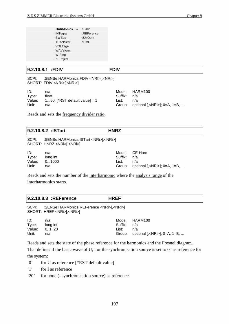
Z E S ZIMMER Electronic Systems GmbH Chapter 9
197
:HARMonics →→→→ :FDIV
:INTegral :REFerence:SWEep :SMOoth:TRANsient :TIME:VOLTage:WAVeform:WIRing:ZPReject
9.2.10.8.1 :FDIV FDIV
SCPI: :SENSe:HARMonics:FDIV <NRf>[,<NRi>]SHORT: FDIV <NRf>[,<NRi>]
ID: n/a Mode: HARM100Type: float Suffix: n/aValue: 1...50, [*RST default value] = 1 List: n/aUnit: n/a Group: optional [,<NRi>]; 0=A, 1=B, ...
Reads and sets the frequency divider ratio.
9.2.10.8.2 :ISTart HNRZ
SCPI: :SENSe:HARMonics:ISTart <NRi>[,<NRi>]SHORT: HNRZ <NRi>[,<NRi>]
ID: n/a Mode: CE-HarmType: long int Suffix: n/aValue: 0...1000 List: n/aUnit: n/a Group: optional [,<NRi>]; 0=A, 1=B, ...
Reads and sets the number of the interharmonic where the analysis range of the
interharmonics starts.
9.2.10.8.3 :REFerence HREF
SCPI: :SENSe:HARMonics:REFerence <NRi>[,<NRi>]SHORT: HREF <NRi>[,<NRi>]
ID: n/a Mode: HARM100Type: long int Suffix: n/aValue: 0, 1, 20 List: n/aUnit: n/a Group: optional [,<NRi>]; 0=A, 1=B, ...
Reads and sets the state of the phase reference for the harmonics and the Fresnel diagram.
That defines if the basic wave of U, I or the synchronisation source is set to 0° as reference for
the system:
‘0’ for U as reference [*RST default value]
‘1’ for I as reference
‘20’ for none (=synchronisation source) as reference

Interfaces (IEEE option L50-O1) LMG500
198
9.2.10.8.4 :SMOoth SMOO
SCPI: :SENSe:HARMonics:SMOoth <NRi>SHORT: SMOO <NRi>
ID: n/a Mode: CE-HarmType: long int Suffix: n/aValue: 0, 1 List: n/aUnit: n/a Group: n/a
Reads and sets the state of the smoothing:
‘0’ or ‘OFF’ for direct measuring [*RST default value]
‘1’ or ‘ON’ for smoothed measuring
9.2.10.8.5 :TIME HTIM
SCPI: :SENSe:HARMonics:TIME <NRi>SHORT: HTIM <NRi>
ID: n/a Mode: CE-HarmType: long int Suffix: n/aValue: n/a, [*RST default value] = 150 List: n/aUnit: s Group: n/a
Reads and sets the harmonics measuring time.
9.2.10.9 :INTegral
:CALCulate:DISPlay:FETCh:FORMat:INITiate:INPut:INSTrument:MEMory:READ
:SENSe →→→→ :AINPut
:SOURce :ARON:STATus :AVERage:SYSTem :CURRent:TRIGger :FILTer
:FINPut:FLICker:HARMonics
:INTegral →→→→ :DATE
:SWEep :INTerval:TRANsient :MODE:VOLTage :STATe:WAVeform :TIME:WIRing:ZPReject
9.2.10.9.1 :DATE INTD
SCPI: :SENSe:INTegral:DATE <NRf>,<NRf>,<NRf>SHORT: INTD <NRf>,<NRf>,<NRf>
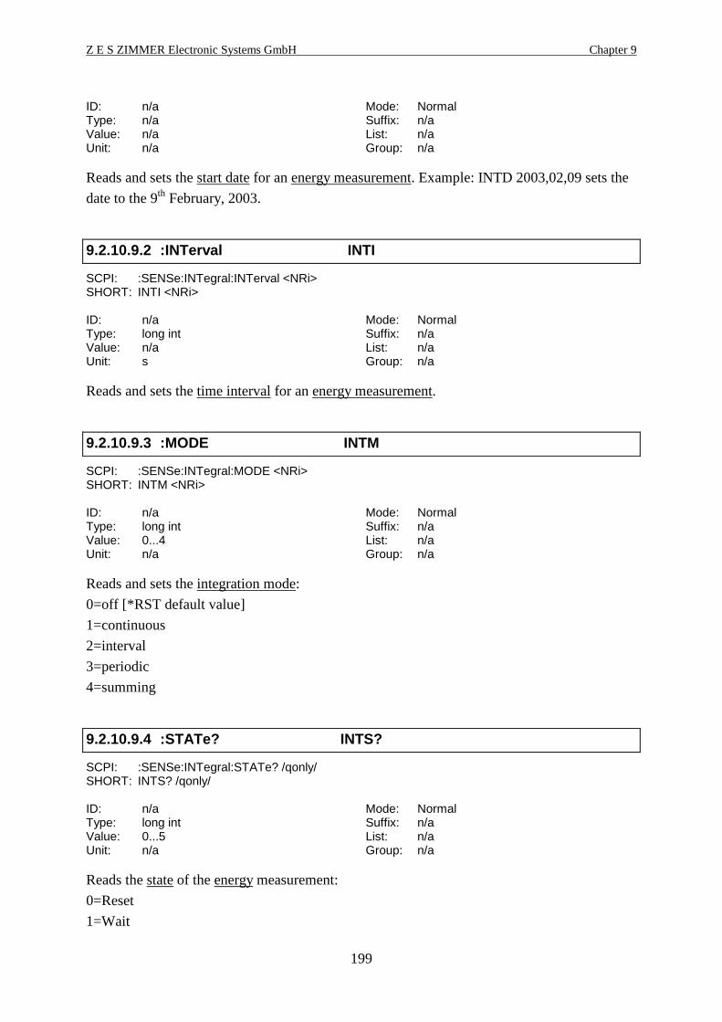
Z E S ZIMMER Electronic Systems GmbH Chapter 9
199
ID: n/a Mode: NormalType: n/a Suffix: n/aValue: n/a List: n/aUnit: n/a Group: n/a
Reads and sets the start date for an energy measurement. Example: INTD 2003,02,09 sets the
date to the 9th February, 2003.
9.2.10.9.2 :INTerval INTI
SCPI: :SENSe:INTegral:INTerval <NRi>SHORT: INTI <NRi>
ID: n/a Mode: NormalType: long int Suffix: n/aValue: n/a List: n/aUnit: s Group: n/a
Reads and sets the time interval for an energy measurement.
9.2.10.9.3 :MODE INTM
SCPI: :SENSe:INTegral:MODE <NRi>SHORT: INTM <NRi>
ID: n/a Mode: NormalType: long int Suffix: n/aValue: 0...4 List: n/aUnit: n/a Group: n/a
Reads and sets the integration mode:
0=off [*RST default value]
1=continuous
2=interval
3=periodic
4=summing
9.2.10.9.4 :STATe? INTS?
SCPI: :SENSe:INTegral:STATe? /qonly/SHORT: INTS? /qonly/
ID: n/a Mode: NormalType: long int Suffix: n/aValue: 0...5 List: n/aUnit: n/a Group: n/a
Reads the state of the energy measurement:
0=Reset
1=Wait

Interfaces (IEEE option L50-O1) LMG500
200
2=Start
3=Run
4=Stop
5=Hold
9.2.10.9.5 :TIME INTT
SCPI: :SENSe:INTegral:TIME <NRf>,<NRf>,<NRf>SHORT: INTT <NRf>,<NRf>,<NRf>
ID: n/a Mode: NormalType: n/a Suffix: n/aValue: n/a List: n/aUnit: n/a Group: n/a
Reads and sets the start time for an energy measurement. Example: INTT 19,26,49 sets the
time to 19:26:49.
9.2.10.10 :RPValues RPHV
SCPI: :SENSe:RPValues <NRi>SHORT: RPHV <NRi>
ID: n/a Mode: AllType: long int Suffix: n/aValue: 0, 1 List: n/aUnit: n/a Group: n/a
By this you can deactivate the rejection of phantom values:
0: Phantom values are displayed
1: Phantom values are not displayed [*RST default value]
9.2.10.11 :SWEep
:CALCulate:DISPlay:FETCh:FORMat:INITiate:INPut:INSTrument:MEMory:READ
:SENSe →→→→ :AINPut
:SOURce :ARON:STATus :AVERage:SYSTem :CURRent:TRIGger :FILTer
:FINPut:FLICker:HARMonics:INTegral

Z E S ZIMMER Electronic Systems GmbH Chapter 9
201
:SWEep →→→→ :TIME
:TRANsient:VOLTage:WAVeform:WIRing:ZPReject
9.2.10.11.1 :TIME CYCL Cycle
SCPI: :SENSe:SWEep:TIME <NRf>SHORT: CYCL <NRf>
ID: Cycle Mode: NormalType: float Suffix: n/aValue: 0, 0.05...60, [*RST default value] = 0.5 List: n/aUnit: s Group: n/a
Reads and sets the cycle time.
9.2.10.12 :TRANsient
:CALCulate:DISPlay:FETCh:FORMat:INITiate:INPut:INSTrument:MEMory:READ
:SENSe →→→→ :AINPut
:SOURce :ARON:STATus :AVERage:SYSTem :CURRent:TRIGger :FILTer
:FINPut:FLICker:HARMonics:INTegral:SWEep
:TRANsient →→→→ :ACRegister
:VOLTage :LIMita:WAVeform :LIMitb:WIRing :DURation:ZPReject :OCRegister
:RTIMe:SIGNal
9.2.10.12.1 :ACRegister TACR
SCPI: :SENSe:TRANsient:ACRegister <NRi>SHORT: TACR <NRi>
ID: n/a Mode: NormalType: long int Suffix: 1...8Value: 0, 1 List: n/aUnit: n/a Group: n/a
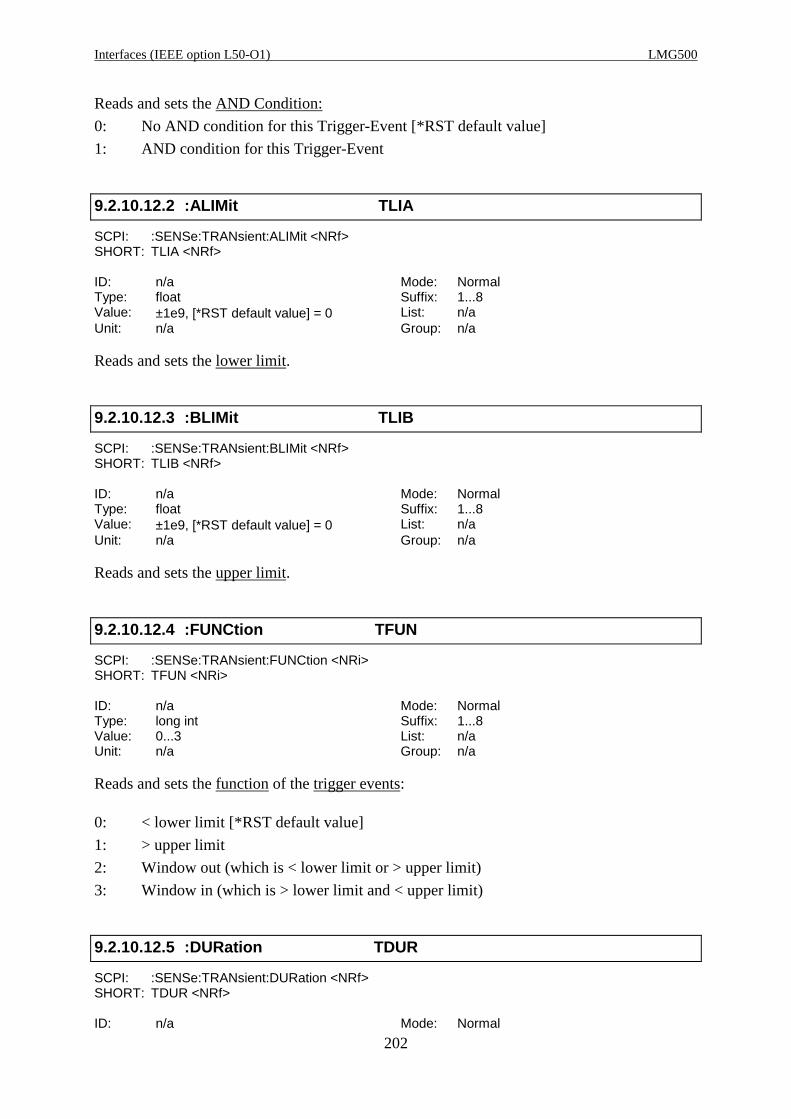
Interfaces (IEEE option L50-O1) LMG500
202
Reads and sets the AND Condition:
0: No AND condition for this Trigger-Event [*RST default value]
1: AND condition for this Trigger-Event
9.2.10.12.2 :ALIMit TLIA
SCPI: :SENSe:TRANsient:ALIMit <NRf>SHORT: TLIA <NRf>
ID: n/a Mode: NormalType: float Suffix: 1...8Value: ±1e9, [*RST default value] = 0 List: n/aUnit: n/a Group: n/a
Reads and sets the lower limit.
9.2.10.12.3 :BLIMit TLIB
SCPI: :SENSe:TRANsient:BLIMit <NRf>SHORT: TLIB <NRf>
ID: n/a Mode: NormalType: float Suffix: 1...8Value: ±1e9, [*RST default value] = 0 List: n/aUnit: n/a Group: n/a
Reads and sets the upper limit.
9.2.10.12.4 :FUNCtion TFUN
SCPI: :SENSe:TRANsient:FUNCtion <NRi>SHORT: TFUN <NRi>
ID: n/a Mode: NormalType: long int Suffix: 1...8Value: 0...3 List: n/aUnit: n/a Group: n/a
Reads and sets the function of the trigger events:
0: < lower limit [*RST default value]
1: > upper limit
2: Window out (which is < lower limit or > upper limit)
3: Window in (which is > lower limit and < upper limit)
9.2.10.12.5 :DURation TDUR
SCPI: :SENSe:TRANsient:DURation <NRf>SHORT: TDUR <NRf>
ID: n/a Mode: Normal
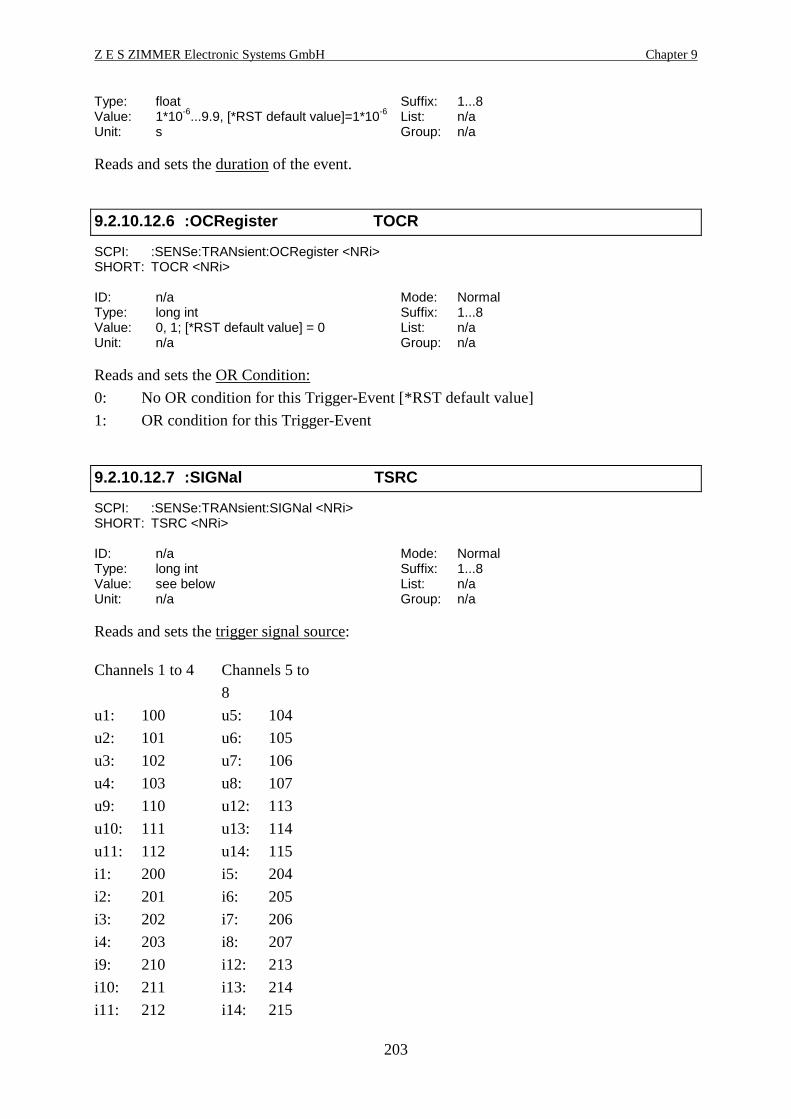
Z E S ZIMMER Electronic Systems GmbH Chapter 9
203
Type: float Suffix: 1...8Value: 1*10-6...9.9, [*RST default value]=1*10-6 List: n/aUnit: s Group: n/a
Reads and sets the duration of the event.
9.2.10.12.6 :OCRegister TOCR
SCPI: :SENSe:TRANsient:OCRegister <NRi>SHORT: TOCR <NRi>
ID: n/a Mode: NormalType: long int Suffix: 1...8Value: 0, 1; [*RST default value] = 0 List: n/aUnit: n/a Group: n/a
Reads and sets the OR Condition:
0: No OR condition for this Trigger-Event [*RST default value]
1: OR condition for this Trigger-Event
9.2.10.12.7 :SIGNal TSRC
SCPI: :SENSe:TRANsient:SIGNal <NRi>SHORT: TSRC <NRi>
ID: n/a Mode: NormalType: long int Suffix: 1...8Value: see below List: n/aUnit: n/a Group: n/a
Reads and sets the trigger signal source:
Channels 1 to 4 Channels 5 to
8
u1: 100 u5: 104
u2: 101 u6: 105
u3: 102 u7: 106
u4: 103 u8: 107
u9: 110 u12: 113
u10: 111 u13: 114
u11: 112 u14: 115
i1: 200 i5: 204
i2: 201 i6: 205
i3: 202 i7: 206
i4: 203 i8: 207
i9: 210 i12: 213
i10: 211 i13: 214
i11: 212 i14: 215

Interfaces (IEEE option L50-O1) LMG500
204
p1: 300 p5: 304
p2: 301 p6: 305
p3: 302 p7: 306
p4: 303 p8: 307
p9: 310 p12: 313
p10: 311 p13: 314
p11: 312 p14: 315
9.2.10.13 :VOLTage
9.2.10.13.1 :DELay UDLY
SCPI: :SENSe:VOLTage:DELay <NRi>SHORT: UDLY <NRi>
ID: n/a Mode: AllType: long int Suffix: 1...8Value: -2666...+2666, [*RST default value] = 0 List: n/aUnit: ns Group: n/a
Reads and sets the delay of the voltage input in ns. Positive values symbolize a delay, negative
values a negative delay!
Example: You have a voltage sensor with a group delay of +150ns. If you want to correct this
group delay, you have to set the voltage delay to -150ns.
9.2.10.13.2 :DETector UEXT
SCPI: :SENSe:VOLTage:DETector <NRi>SHORT: UEXT <NRi>
ID: n/a Mode: AllType: long int Suffix: 1...8Value: 0, 1 List: n/aUnit: n/a Group: n/a
Reads and sets the jack for the voltage input:
‘0’ or ‘INT’ for voltage at U* jack [*RST default value]
‘1’ or ‘EXT’ for voltage at USensor (sensor input)
9.2.10.13.3 :IDENtify IDNU
SCPI: :SENSe:VOLTage:IDENtify? /qonly/SHORT: IDNU? /qonly/
ID: n/a Mode: AllType: string Suffix: 1...8Value: n/a List: n/aUnit: n/a Group: n/a
Reads the type of an external voltage sensor. The LMG will always return „No sensor input“.
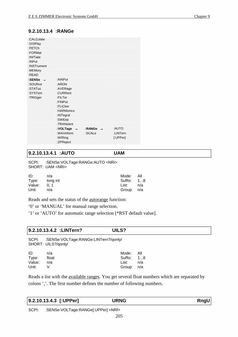
Z E S ZIMMER Electronic Systems GmbH Chapter 9
205
9.2.10.13.4 :RANGe
:CALCulate:DISPlay:FETCh:FORMat:INITiate:INPut:INSTrument:MEMory:READ
:SENSe →→→→ :AINPut
:SOURce :ARON:STATus :AVERage:SYSTem :CURRent:TRIGger :FILTer
:FINPut:FLICker:HARMonics:INTegral:SWEep:TRANsient
:VOLTage →→→→ :RANGe →→→→ :AUTO
:WAVeform :SCALe :LINTern:WIRing [:UPPer]:ZPReject
9.2.10.13.4.1 :AUTO UAM
SCPI: :SENSe:VOLTage:RANGe:AUTO <NRi>SHORT: UAM <NRi>
ID: n/a Mode: AllType: long int Suffix: 1...8Value: 0, 1 List: n/aUnit: n/a Group: n/a
Reads and sets the status of the autorange function:
‘0’ or ‘MANUAL’ for manual range selection.
‘1’ or ‘AUTO’ for automatic range selection [*RST default value].
9.2.10.13.4.2 :LINTern? UILS?
SCPI: :SENSe:VOLTage:RANGe:LINTern?/qonly/SHORT: UILS?/qonly/
ID: n/a Mode: AllType: float Suffix: 1...8Value: n/a List: n/aUnit: V Group: n/a
Reads a list with the available ranges. You get several float numbers which are separated by
colons ‘,’. The first number defines the number of following numbers.
9.2.10.13.4.3 [:UPPer] URNG RngU
SCPI: :SENSe:VOLTage:RANGe[:UPPer] <NRf>

Interfaces (IEEE option L50-O1) LMG500
206
SHORT: URNG <NRf>
ID: RngU Mode: AllType: float Suffix: 1...8Value: n/a List: n/aUnit: V Group: n/a
Reads and sets the range for the voltage measurement. The parameter is the nominal value of
the range.
9.2.10.13.5 :SCALe USCA Uscal
SCPI: :SENSe:VOLTage:SCALe <NRf>SHORT: USCA <NRf>
ID: Uscal Mode: AllType: float Suffix: 1...8Value: n/a, [*RST default value] = 1 List: n/aUnit: n/a Group: n/a
Reads and sets the scaling of the voltage range.
9.2.10.14 :WAVeform
:CALCulate:DISPlay:FETCh:FORMat:INITiate:INPut:INSTrument:MEMory:READ
:SENSe →→→→ :AINPut
:SOURce :ARON:STATus :AVERage:SYSTem :CURRent:TRIGger :FILTer
:FINPut:FLICker:HARMonics:INTegral:SWEep:TRANsient:VOLTage
:WAVeform →→→→ :CYCLes
:WIRing :IUPDate:ZPReject :SATRigger
:SBTRigger:SCTRigger:SRATe:WAVE
9.2.10.14.1 :DIVision GBAS
SCPI: :SENSe:WAVeform:DIVision <NRf>SHORT: GBAS <NRf>

Z E S ZIMMER Electronic Systems GmbH Chapter 9
207
ID: n/a Mode: NormalType: float Suffix: n/aValue: 10e-6...1 List: n/aUnit: s Group: n/a
Reads or sets the timebase of the scope display (1-2-5 division). By this the record rate will be
changed (requestable via GFRQ command). The smalles possible timebase depends on the
following circumstances:
- cycle time
- chosen filter
- number of channels.
See also 11.1.3, ‘Hints for setting up the record rate of the scope’
9.2.10.14.2 :IUPDate SACT
SCPI: :SENSe:WAVeform:IUPDate/nquery/ [<NRi>]SHORT: SACT/nquery/ [<NRi>]
ID: n/a Mode: AllType: n/a Suffix: n/aValue: n/a List: n/aUnit: n/a Group: optional [<NRi>], 0=A, 1=B, ...
Requests to update the the information about the scope data. Before this command you should
set ‘:MEMory:FREeze ON’. After this command you can use ‘:SENS:WAV:SATR’,
‘:SENS:WAV:SBTR’ and ‘:SENS:WAV:SCTT’. This command itself doesn’t return any
values!
9.2.10.14.3 :SATRigger? SATR?
SCPI: :SENSe:WAVeform:SATRigger? /qonly/ [<NRi>]SHORT: SATR? /qonly/ [<NRi>]
ID: n/a Mode: AllType: long int Suffix: n/aValue: n/a List: n/aUnit: n/a Group: optional [<NRi>], 0=A, 1=B, ...
Reads how many sample values are available after the trigger event. See also
‘:SENS:WAV:IUPD’ for further information.
9.2.10.14.4 :SBTRigger? SBTR?
SCPI: :SENSe:WAVeform:SBTRigger? /qonly/ [<NRi>]SHORT: SBTR? /qonly/ [<NRi>]
ID: n/a Mode: AllType: long int Suffix: n/aValue: n/a List: n/aUnit: n/a Group: optional [<NRi>], 0=A, 1=B, ...

Interfaces (IEEE option L50-O1) LMG500
208
Reads how many sample values are available before the trigger event. See also
‘:SENS:WAV:IUPD’ for further information.
9.2.10.14.5 :SCTRigger? SCTT?
SCPI: :SENSe:WAVeform:SCTRigger? /qonly/SHORT: SCTT? /qonly/
ID: n/a Mode: AllType: long int Suffix: n/aValue: 0...231-1 List: n/aUnit: n/a Group: n/a
Reads the number of the sample value at the trigger. See also ‘:SENS:WAV:IUPD’ for further
information. The sample values of the instrument are counted. At the end of each cycle this
counter is stored and can be read by this command. The counter runs up to 231-1 and starts
then again at 0. See also 9.2.4.1.2.2, ‘:SNUMber? SCTC?’
You always get the value of group A.
9.2.10.14.6 :SRATe? GFRQ?
SCPI: :SENSe:WAVeform:SRATe? [<NRi>]/qonly/SHORT: GFRQ? [<NRi>]/qonly/
ID: n/a Mode: AllType: float Suffix: n/aValue: n/a List: n/aUnit: n/a Group: optional [<NRi>], 0=A, 1=B, ...
Reads the record rate of the sampled values.
9.2.10.14.7 :WAVE? WAVE?
SCPI: :SENSe:WAVeform:WAVE? /qonly/ <NRi>,<list>SHORT: WAVE? /qonly/ <NRi>,<list>
ID: n/a Mode: AllType: float Suffix: 1...14Value: n/a List: see belowUnit: n/a Group: n/a
Before using this command you should freeze the memory with :MEMory:FREeze, to avoid
data losses at long transfer duration. Reads out sample values specified with <NRi>:
4: i
5: u
6: p
The first allowed value in <list> is the value read by :SENSe:WAVeform:SBTRigger?, the
last allowed value that read by :SENSe:WAVeform:SATRigger?
Z E S ZIMMER Electronic Systems GmbH Chapter 9
209
9.2.10.15 :WIRing WIRE
SCPI: :SENSe:WIRing <NRi>[,<NRi>]SHORT: WIRE <NRi>[,<NRi>]
ID: n/a Mode: Normal, HARM100Type: long int Suffix: n/aValue: 0...5, 8...15 List: n/aUnit: n/a Group: n/a
Sets or queries the wiring of the LMG. Following values are allowed (3 to 7 only with option
L45-O6 star to delta conversion!):
0: Wiring ‘4+0’
1: Wiring ‘3+1’ [*RST default value with 4 installed channels]
2: Wiring ‘2+2’
3: Wiring ‘3+1, U*I*->U∆I∆‘
4: Wiring ‘3+1, U∆I*->U ∆I∆‘
5: Wiring ‘3+1, U∆I*->U*I*‘
6, 7: not used
8: Wiring ‘1+0’ [*RST default value with 1 installed channel]
9: Wiring ‘2+0’
10: Wiring ‘1+1’ [*RST default value with 2 installed channels]
11: Wiring ‘3+0’ [*RST default value with 3 installed channels]
12: Wiring ‘3+0, U*I*->U∆I∆‘
13: Wiring ‘3+0, U∆I*->U ∆I∆‘
14: Wiring ‘3+0, U∆I*->U*I*‘
15: Wiring ‘2+1’
The optional [,<NRi>] specifies, if the master instrument (=0, default) or slave instrument
(=1) should be setup. If you request the wiring from the slave but there is no slave connected,
the answer will be -1.
In a big, combined instrument, the channels 1-4 are master instrument channels, the channels
5-8 are slave instrument channels. This is, because such instruments are internally build up as
a master-slave system.
9.2.10.16 :ZPReject ZSUP
SCPI: :SENSe:ZPReject <NRi>SHORT: ZSUP <NRi>
ID: n/a Mode: NormalType: long int Suffix: n/aValue: 0, 1 List: n/aUnit: n/a Group: n/a
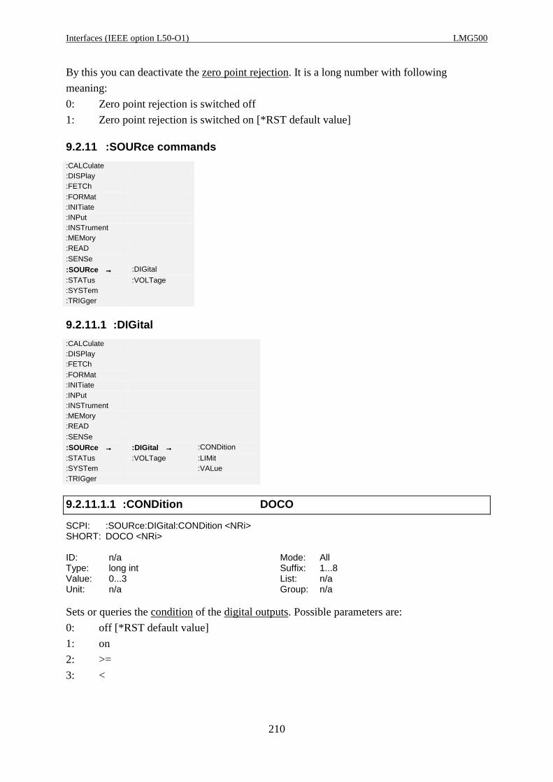
Interfaces (IEEE option L50-O1) LMG500
210
By this you can deactivate the zero point rejection. It is a long number with following
meaning:
0: Zero point rejection is switched off
1: Zero point rejection is switched on [*RST default value]
9.2.11 :SOURce commands
:CALCulate:DISPlay:FETCh:FORMat:INITiate:INPut:INSTrument:MEMory:READ:SENSe
:SOURce →→→→ :DIGital
:STATus :VOLTage:SYSTem:TRIGger
9.2.11.1 :DIGital
:CALCulate:DISPlay:FETCh:FORMat:INITiate:INPut:INSTrument:MEMory:READ:SENSe
:SOURce →→→→ :DIGital →→→→ :CONDition
:STATus :VOLTage :LIMit:SYSTem :VALue:TRIGger
9.2.11.1.1 :CONDition DOCO
SCPI: :SOURce:DIGital:CONDition <NRi>SHORT: DOCO <NRi>
ID: n/a Mode: AllType: long int Suffix: 1...8Value: 0...3 List: n/aUnit: n/a Group: n/a
Sets or queries the condition of the digital outputs. Possible parameters are:
0: off [*RST default value]
1: on
2: >=
3: <

Z E S ZIMMER Electronic Systems GmbH Chapter 9
211
9.2.11.1.2 :LIMit DOLI
SCPI: :SOURce:DIGital:LIMit <NRf>SHORT: DOLI <NRf>
ID: n/a Mode: AllType: float Suffix: 1...8Value: n/a, [*RST default value] = 0 List: n/aUnit: n/a Group: n/a
Sets or queries the setting of the limits of the digital outputs.
9.2.11.1.3 :VALue DOIX
SCPI: :SOURce:DIGital:VALue <string>SHORT: DOIX <string>
ID: n/a Mode: AllType: string Suffix: 1...8Value: n/a, [*RST default value] = ‘Utrms’ List: n/aUnit: n/a Group: n/a
Sets or queries the setting of the value of the digital outputs. As <string> you have to enter the
same string as you would enter when using the instrument without interface. So you have to
sent a valid ID!
9.2.11.2 :VOLTage
9.2.11.2.1 :SCALe
:CALCulate:DISPlay:FETCh:FORMat:INITiate:INPut:INSTrument:MEMory:READ:SENSe
:SOURce →→→→ :DIGital
:STATus :VOLTage →→→→ :SCALe →→→→ :FSCale
:SYSTem :VALue :ZERO:TRIGger
9.2.11.2.1.1 :FSCale AOHI
SCPI: :SOURce:VOLTage:SCALe:FSCale <NRf>SHORT: AOHI <NRf>
ID: n/a Mode: AllType: float Suffix: 1...8Value: n/a, [*RST default value] = 10 List: n/aUnit: n/a Group: n/a

Interfaces (IEEE option L50-O1) LMG500
212
Sets or queries the setting of the full scale of the analogue outputs.
9.2.11.2.1.2 :ZERO AOLO
SCPI: :SOURce:VOLTage:SCALe:ZERO <NRf>SHORT: AOLO <NRf>
ID: n/a Mode: AllType: float Suffix: 1...8Value: n/a, [*RST default value] = 0 List: n/aUnit: n/a Group: n/a
Sets or queries the setting of the zero position of the analogue outputs.
9.2.11.2.2 :VALue AOIX
SCPI: :SOURce:VOLTage:VALue <string>SHORT: AOIX <string>
ID: n/a Mode: AllType: string Suffix: 1...8Value: n/a, [*RST default value] = „Utrms“ List: n/aUnit: n/a Group: n/a
Sets or queries the setting of the value of the analogue outputs. As <string> you have to enter
the same string as you would enter when using the instrument without interface. So you have
to send a valid ID!
9.2.12 :STATus commands
9.2.12.1 :OPERation
:CALCulate:DISPlay:FETCh:FORMat:INITiate:INPut:INSTrument:MEMory:READ:SENSe:SOURce
:STATus →→→→ :OPERation →→→→ :CONDition
:SYSTem :PRESet :ENABle:TRIGger :QUEStionable [:EVENt]
:NTRansition:PTRansition
9.2.12.1.1 :CONDition? SOC?
SCPI: :STATus:OPERation:CONDition? /qonly/SHORT: SOC? /qonly/

Z E S ZIMMER Electronic Systems GmbH Chapter 9
213
ID: n/a Mode: AllType: long int Suffix: n/aValue: 0...65535 List: n/aUnit: n/a Group: n/a
Reads the Operation Status Condition Register.
9.2.12.1.2 :ENABle SOEN
SCPI: :STATus:OPERation:ENABle <NRi>SHORT: SOEN <NRi>
ID: n/a Mode: AllType: long int Suffix: n/aValue: 0...65535 List: n/aUnit: n/a Group: n/a
Reads and sets the Operation Status Enable Register.
9.2.12.1.3 [:EVENt]? SOE?
SCPI: :STATus:OPERation[:EVENt]? /qonly/SHORT: SOE? /qonly/
ID: n/a Mode: AllType: long int Suffix: n/aValue: 0...65535 List: n/aUnit: n/a Group: n/a
Reads the Operation Status Event Register and clears it.
9.2.12.1.4 :NTRansition SONT
SCPI: :STATus:OPERation:NTRansition <NRi>SHORT: SONT <NRi>
ID: n/a Mode: AllType: long int Suffix: n/aValue: 0...65535 List: n/aUnit: n/a Group: n/a
Reads and sets the Operation Status Negative Transition Register.
9.2.12.1.5 :PTRansition SOPT
SCPI: :STATus:OPERation:PTRansition <NRi>SHORT: SOPT <NRi>
ID: n/a Mode: AllType: long int Suffix: n/aValue: 0...65535 List: n/aUnit: n/a Group: n/a
Reads and sets the Operation Status Positive Transition Register.

Interfaces (IEEE option L50-O1) LMG500
214
9.2.12.2 PRESet PRES
SCPI: :STATus:PRESet/nquery/SHORT: PRES/nquery/
ID: n/a Mode: AllType: n/a Suffix: n/aValue: n/a List: n/aUnit: n/a Group: n/a
Presets the operation and the query registers. The p-transition registers are filled with 0x7FFF,
the n-transition registers with 0x0000 and the enable registers with 0x0000.
9.2.12.3 :QUEStionable
:CALCulate:DISPlay:FETCh:FORMat:INITiate:INPut:INSTrument:MEMory:READ:SENSe:SOURce
:STATus →→→→ :OPERation
:SYSTem :PRESet:TRIGger :QUEStionable →→→→ :CONDition
:ENABle[:EVENt]:NTRansition:PTRansition
9.2.12.3.1 :CONDition? SQC?
SCPI: :STATus:QUEStionable:CONDition? /qonly/SHORT: SQC? /qonly/
ID: n/a Mode: AllType: long int Suffix: n/aValue: 0...65535 List: n/aUnit: n/a Group: n/a
Reads the Questionable Status Condition Register.
9.2.12.3.2 :ENABle SQEN
SCPI: :STATus:QUEStionable:ENABle <NRi>SHORT: SQEN <NRi>
ID: n/a Mode: AllType: long int Suffix: n/aValue: 0...65535 List: n/aUnit: n/a Group: n/a
Reads and sets the Questionable Status Enable Register.
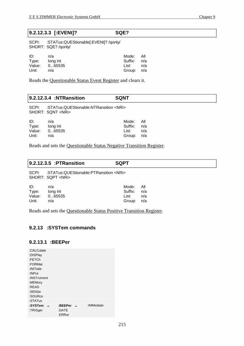
Z E S ZIMMER Electronic Systems GmbH Chapter 9
215
9.2.12.3.3 [:EVENt]? SQE?
SCPI: :STATus:QUEStionable[:EVENt]? /qonly/SHORT: SQE? /qonly/
ID: n/a Mode: AllType: long int Suffix: n/aValue: 0...65535 List: n/aUnit: n/a Group: n/a
Reads the Questionable Status Event Register and clears it.
9.2.12.3.4 :NTRansition SQNT
SCPI: :STATus:QUEStionable:NTRansition <NRi>SHORT: SQNT <NRi>
ID: n/a Mode: AllType: long int Suffix: n/aValue: 0...65535 List: n/aUnit: n/a Group: n/a
Reads and sets the Questionable Status Negative Transition Register.
9.2.12.3.5 :PTRansition SQPT
SCPI: :STATus:QUEStionable:PTRansition <NRi>SHORT: SQPT <NRi>
ID: n/a Mode: AllType: long int Suffix: n/aValue: 0...65535 List: n/aUnit: n/a Group: n/a
Reads and sets the Questionable Status Positive Transition Register.
9.2.13 :SYSTem commands
9.2.13.1 :BEEPer
:CALCulate:DISPlay:FETCh:FORMat:INITiate:INPut:INSTrument:MEMory:READ:SENSe:SOURce:STATus
:SYSTem →→→→ :BEEPer →→→→ :IMMediate
:TRIGger :DATE:ERRor

Interfaces (IEEE option L50-O1) LMG500
216
:HELP:KEY:LANGuage:OPTions:PHEADER:TIME:VERSion
9.2.13.1.1 :IMMediate BEEP
SCPI: :SYSTem:BEEPer:IMMediate/nquery/SHORT: BEEP/nquery/
ID: n/a Mode: AllType: n/a Suffix: n/aValue: n/a List: n/aUnit: n/a Group: n/a
Forces the internal beeper to produce a short sound.
9.2.13.2 :DATE DATE
SCPI: :SYSTem:DATE <NRf>,<NRf>,<NRf>SHORT: DATE <NRf>,<NRf>,<NRf>
ID: n/a Mode: AllType: n/a Suffix: n/aValue: n/a List: n/aUnit: n/a Group: n/a
Reads and sets the system date. Format is DATE yyyy,mm,dd. Example: DATE 2003,02,09
sets the date to the 9th February, 2003.
9.2.13.3 :ERRor
Following errors can occur:
No. Name Possible reason; what to do
8 Overrun error at CONT ON Too many values were requested in a too short time
7 Nested TRIGger:ACTion not
allowed
6 Action Buffer Overrun Too many commands after the TRIGger:ACTion
command
5 Command header error; (or
maybe wrong path before)
Not existing or misspelled command or wrong SCPI
path
4 Formatter output has overrun Internal error, please contact ZES
2 Parser output has overrun Internal error, please contact ZES
1 Parser deadlocked Internal error, please contact ZES
0 No error -
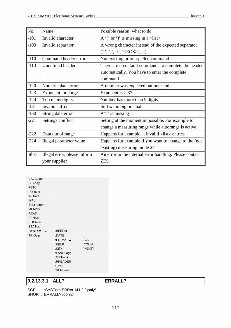
Z E S ZIMMER Electronic Systems GmbH Chapter 9
217
No. Name Possible reason; what to do
-101 Invalid character A ‘(‘ or ‘)’ is missing in a <list>
-103 Invalid separator A wrong character instead of the expected separator
(‘,’, ‘;’, ‘:’, ‘<EOS>‘, ...)
-110 Command header error Not existing or misspelled command
-113 Undefined header There are no default commands to complete the header
automatically. You have to enter the complete
command
-120 Numeric data error A number was expected but not send
-123 Exponent too large Exponent is > 37
-124 Too many digits Number has more than 9 digits
-131 Invalid suffix Suffix too big or small
-150 String data error A’“’ is missing
-221 Settings conflict Setting at the moment impossible. For example to
change a measuring range while autorange is active
-222 Data out of range Happens for example at invalid <list> entries
-224 Illegal parameter value Happens for example if you want to change to the (not
existing) measuring mode 27
other Illegal error, please inform
your supplier
An error in the internal error handling. Please contact
ZES
:CALCulate:DISPlay:FETCh:FORMat:INITiate:INPut:INSTrument:MEMory:READ:SENSe:SOURce:STATus
:SYSTem →→→→ :BEEPer
:TRIGger :DATE
:ERRor →→→→ :ALL
:HELP :COUNt:KEY [:NEXT]:LANGuage:OPTions:PHEADER:TIME:VERSion
9.2.13.3.1 :ALL? ERRALL?
SCPI: :SYSTem:ERRor:ALL? /qonly/SHORT: ERRALL? /qonly/
Interfaces (IEEE option L50-O1) LMG500
218
ID: n/a Mode: AllType: n/a Suffix: n/aValue: n/a List: n/aUnit: n/a Group: n/a
Reads all errors, including error code and error description, separated by colons out of the
error/event queue.
9.2.13.3.2 :COUNt? ERRCNT?
SCPI: :SYSTem:ERRor:COUNt? /qonly/SHORT: ERRCNT? /qonly/
ID: n/a Mode: AllType: long int Suffix: n/aValue: n/a List: n/aUnit: n/a Group: n/a
Reads the number of errors in the error/event queue.
9.2.13.3.3 [:NEXT]? ERR?
SCPI: :SYSTem:ERRor[:NEXT]? /qonly/SHORT: ERR? /qonly/
ID: n/a Mode: AllType: n/a Suffix: n/aValue: n/a List: n/aUnit: n/a Group: n/a
Reads the oldest entry from the error/event queue, including error code and error description,
separated by colons (‘,’).
9.2.13.4 :HELP
:CALCulate:DISPlay:FETCh:FORMat:INITiate:INPut:INSTrument:MEMory:READ:SENSe:SOURce:STATus
:SYSTem →→→→ :BEEPer
:TRIGger :DATE:ERRor
:HELP →→→→ :HEADers
:KEY :SHEaders:LANGuage:OPTions:PHEADER

Z E S ZIMMER Electronic Systems GmbH Chapter 9
219
:TIME:VERSion
9.2.13.4.1 :HEADers? HEAD?
SCPI: :SYSTem:HELP:HEADers? /qonly/SHORT: HEAD? /qonly/
ID: n/a Mode: AllType: n/a Suffix: n/aValue: n/a List: n/aUnit: n/a Group: n/a
Returns a list of all SCPI headers. This list is a <defined length arbitrary block response data>.
Because this command has a very special output format it should only be used stand alone.
9.2.13.4.2 :SHEaders? SHEAD?
SCPI: :SYSTem:HELP:SHEaders? /qonly/ [<NRi>]SHORT: SHEAD? /qonly/ [<NRi>]
ID: n/a Mode: AllType: n/a Suffix: n/aValue: n/a List: n/aUnit: n/a Group: n/a
Returns a list of all SHORT headers. This list is a <defined length arbitrary block response
data>. Because this command has a very special output format it should only be used stand
alone.
If the optional NRi is ‘0’, then the output is according to SCPI standard. If it is ‘1’ there are
additional information in the format ‘x;y t’:
x, if specified, is the maximum suffix
;y, if specified, is the maximum index
t, if specified, is the data type
9.2.13.5 :KEY KEY
SCPI: :SYSTem:KEY <NRi>SHORT: KEY <NRi>
ID: n/a Mode: AllType: long int Suffix: n/aValue: n/a List: n/aUnit: n/a Group: n/a
Queries the last pressed key or simulates the pressing of a key. Valid key numbers are:
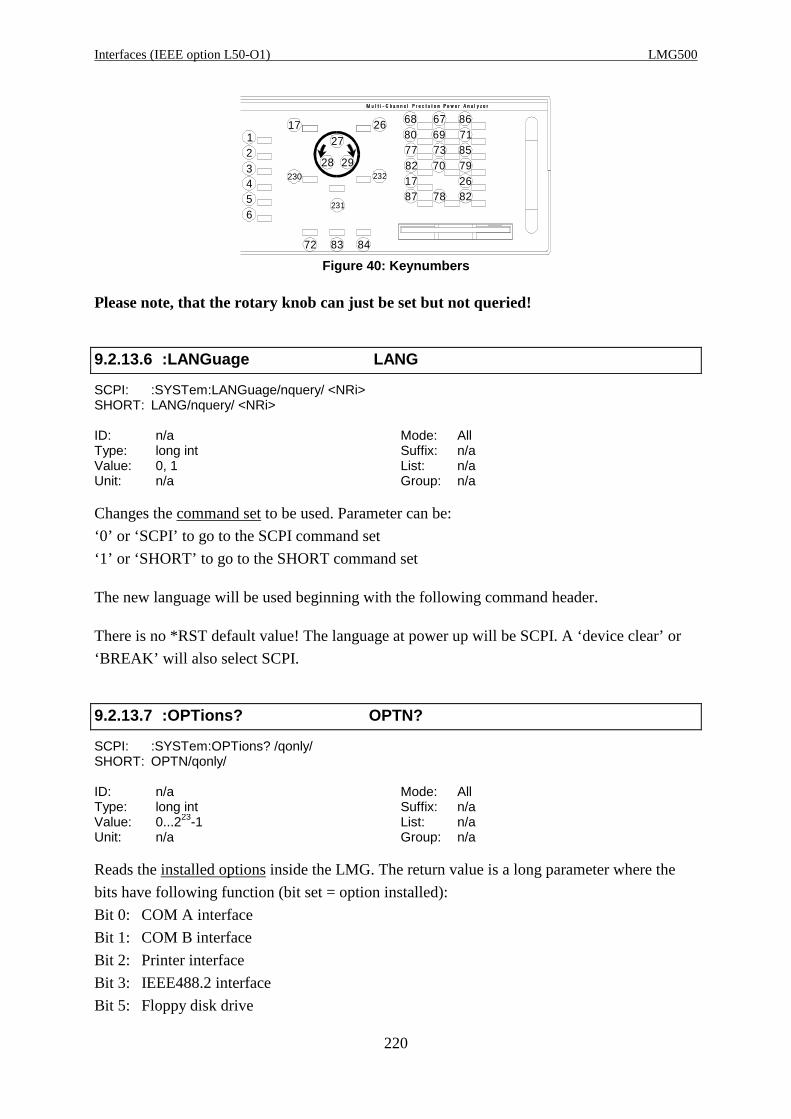
Interfaces (IEEE option L50-O1) LMG500
220
6880 69 71
85737782 70 79
261787 78 82
67 86
27
28 29
72 83 84
123456
17
230
26
232
231
Figure 40: Keynumbers
Please note, that the rotary knob can just be set but not queried!
9.2.13.6 :LANGuage LANG
SCPI: :SYSTem:LANGuage/nquery/ <NRi>SHORT: LANG/nquery/ <NRi>
ID: n/a Mode: AllType: long int Suffix: n/aValue: 0, 1 List: n/aUnit: n/a Group: n/a
Changes the command set to be used. Parameter can be:
‘0’ or ‘SCPI’ to go to the SCPI command set
‘1’ or ‘SHORT’ to go to the SHORT command set
The new language will be used beginning with the following command header.
There is no *RST default value! The language at power up will be SCPI. A ‘device clear’ or
‘BREAK’ will also select SCPI.
9.2.13.7 :OPTions? OPTN?
SCPI: :SYSTem:OPTions? /qonly/SHORT: OPTN/qonly/
ID: n/a Mode: AllType: long int Suffix: n/aValue: 0...223-1 List: n/aUnit: n/a Group: n/a
Reads the installed options inside the LMG. The return value is a long parameter where the
bits have following function (bit set = option installed):
Bit 0: COM A interface
Bit 1: COM B interface
Bit 2: Printer interface
Bit 3: IEEE488.2 interface
Bit 5: Floppy disk drive
Z E S ZIMMER Electronic Systems GmbH Chapter 9
221
Bit 6: Processing signal interface
Bit 8: Flicker
Bit 9: Harm100
Bit 16: Linked values
Bit 17: CE Harmonics
Bit 19: Ethernet LAN
Bit 24: USB interface
Bit 25-27: 3 bit with the number of installed power measuring channels
Bit 28-31: 4 bit with the number of installed DSP
9.2.13.8 :PHEader PHDR
SCPI: :SYSTem:PHEader <string program data>SHORT: PHDR <string program data>
ID: n/a Mode: AllType: string Suffix: n/aValue: n/a List: n/aUnit: n/a Group: n/a
Sets or reads the printer header. At *RST this value is deleted.
For examplePHDR „HELLO“would cause to output „HELLO“ before each printing.
9.2.13.9 :TIME TIME
SCPI: :SYSTem:TIME <NRf>,<NRf>,<NRf>SHORT: TIME <NRf>,<NRf>,<NRf>
ID: n/a Mode: AllType: n/a Suffix: n/aValue: n/a List: n/aUnit: n/a Group: n/a
Reads and sets the system time. Format is TIME hh,mm,ss. Example: TIME 10,26,46 sets the
time to 10:26:46.
9.2.13.10 :VERSion? VER?
SCPI: :SYSTem:VERSion? /qonly/SHORT: VER? /qonly/
ID: n/a Mode: AllType: n/a Suffix: n/aValue: 1999.0 List: n/aUnit: n/a Group: n/a
Returns the version of the SCPI implementation. Returns always ‘1999.0’.

Interfaces (IEEE option L50-O1) LMG500
222
9.2.14 :TRIGger commands
:CALCulate:DISPlay:FETCh:FORMat:INITiate:INPut:INSTrument:MEMory:READ:SENSe:SOURce:STATus:SYSTem
:TRIGger →→→→ :ACTion
:ICURrent:INTerval[:SEQuence]
9.2.14.1 :ACTion ACTN
SCPI: :TRIGger:ACTion/nquery/SHORT: ACTN/nquery/
ID: n/a Mode: AllType: n/a Suffix: n/aValue: n/a List: n/aUnit: n/a Group: n/a
Defines an action which has to be performed, when :INIT:CONT is set to ON and a trigger
event occurs. All program headers which follow behind the ‘;’ after TRIG:ACT will be used,
until the end of the program message.
Example: ACTN;UTRMS?;ITRMS?
This defines that each time a trigger event occurs in the INIT:CONT ON state, the TRMS
values of voltage and current are returned. See also 9.2.6.1, ‘:CONTinuous CONT’. The
same example in SCPI syntax would be.
:TRIG:ACT;:FETC:TRMS?;:FETC:CURR:TRMS?
There is no *RST default value!
9.2.14.2 :ICURrent IINC
SCPI: :TRIGger:ICURrent/nquery/SHORT: IINC/nquery/
ID: n/a Mode: AllType: n/a Suffix: n/aValue: n/a List: n/aUnit: n/a Group: n/a
Triggers the measuring of the inrush current. The value for the inrush current is reset to 0. See
also 9.2.4.1.1.6
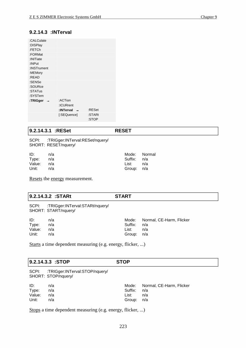
Z E S ZIMMER Electronic Systems GmbH Chapter 9
223
9.2.14.3 :INTerval
:CALCulate:DISPlay:FETCh:FORMat:INITiate:INPut:INSTrument:MEMory:READ:SENSe:SOURce:STATus:SYSTem
:TRIGger →→→→ :ACTion
:ICURrent
:INTerval →→→→ :RESet
[:SEQuence] :STARt:STOP
9.2.14.3.1 :RESet RESET
SCPI: :TRIGger:INTerval:RESet/nquery/SHORT: RESET/nquery/
ID: n/a Mode: NormalType: n/a Suffix: n/aValue: n/a List: n/aUnit: n/a Group: n/a
Resets the energy measurement.
9.2.14.3.2 :STARt START
SCPI: :TRIGger:INTerval:STARt/nquery/SHORT: START/nquery/
ID: n/a Mode: Normal, CE-Harm, FlickerType: n/a Suffix: n/aValue: n/a List: n/aUnit: n/a Group: n/a
Starts a time dependent measuring (e.g. energy, flicker, ...)
9.2.14.3.3 :STOP STOP
SCPI: :TRIGger:INTerval:STOP/nquery/SHORT: STOP/nquery/
ID: n/a Mode: Normal, CE-Harm, FlickerType: n/a Suffix: n/aValue: n/a List: n/aUnit: n/a Group: n/a
Stops a time dependent measuring (e.g. energy, flicker, ...)

Interfaces (IEEE option L50-O1) LMG500
224
9.2.14.3.4 :TREStart TRST
SCPI: :TRIGger:INTerval:TREStart/nquery/SHORT: START/nquery/
ID: n/a Mode: NormalType: n/a Suffix: n/aValue: n/a List: n/aUnit: n/a Group: n/a
(Re)starts the transient search.
9.2.14.3.5 :TSTop TSTP
SCPI: :TRIGger:INTerval:TSTop/nquery/SHORT: TSTP/nquery/
ID: n/a Mode: NormalType: n/a Suffix: n/aValue: n/a List: n/aUnit: n/a Group: n/a
Stops a transient search.
9.2.14.4 [:SEQuence]
:CALCulate:DISPlay:FETCh:FORMat:INITiate:INPut:INSTrument:MEMory:READ:SENSe:SOURce:STATus:SYSTem
:TRIGger →→→→ :ACTion
:ICURrent:INTerval
[:SEQuence] →→→→ :DEModulator
:HPASs:LPASs:SOURce
9.2.14.4.1 :DEModulator TRGA
SCPI: :TRIGger[:SEQuence]:DEModulator <NRi>[,<NRi>]SHORT: TRGA <NRi>[,<NRi>]
ID: n/a Mode: Normal, HARM100Type: long int Suffix: n/aValue: 0...2 List: n/aUnit: n/a Group: optional [,<NRi>], 0=A, 1=B, ...
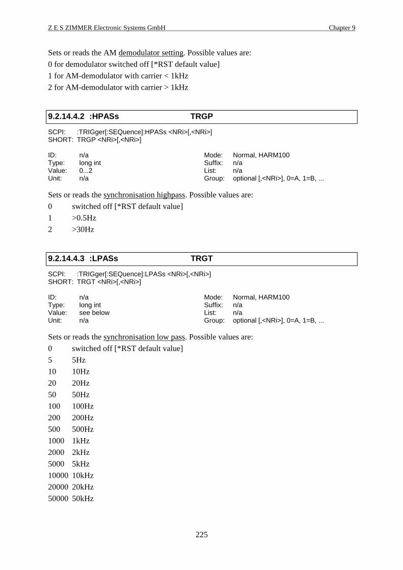
Z E S ZIMMER Electronic Systems GmbH Chapter 9
225
Sets or reads the AM demodulator setting. Possible values are:
0 for demodulator switched off [*RST default value]
1 for AM-demodulator with carrier < 1kHz
2 for AM-demodulator with carrier > 1kHz
9.2.14.4.2 :HPASs TRGP
SCPI: :TRIGger[:SEQuence]:HPASs <NRi>[,<NRi>]SHORT: TRGP <NRi>[,<NRi>]
ID: n/a Mode: Normal, HARM100Type: long int Suffix: n/aValue: 0...2 List: n/aUnit: n/a Group: optional [,<NRi>], 0=A, 1=B, ...
Sets or reads the synchronisation highpass. Possible values are:
0 switched off [*RST default value]
1 >0.5Hz
2 >30Hz
9.2.14.4.3 :LPASs TRGT
SCPI: :TRIGger[:SEQuence]:LPASs <NRi>[,<NRi>]SHORT: TRGT <NRi>[,<NRi>]
ID: n/a Mode: Normal, HARM100Type: long int Suffix: n/aValue: see below List: n/aUnit: n/a Group: optional [,<NRi>], 0=A, 1=B, ...
Sets or reads the synchronisation low pass. Possible values are:
0 switched off [*RST default value]
5 5Hz
10 10Hz
20 20Hz
50 50Hz
100 100Hz
200 200Hz
500 500Hz
1000 1kHz
2000 2kHz
5000 5kHz
10000 10kHz
20000 20kHz
50000 50kHz
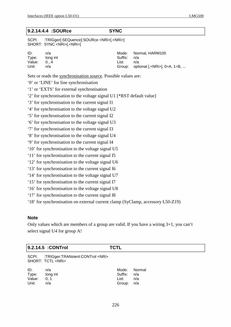
Interfaces (IEEE option L50-O1) LMG500
226
9.2.14.4.4 :SOURce SYNC
SCPI: :TRIGger[:SEQuence]:SOURce <NRi>[,<NRi>]SHORT: SYNC <NRi>[,<NRi>]
ID: n/a Mode: Normal, HARM100Type: long int Suffix: n/aValue: 0...4 List: n/aUnit: n/a Group: optional [,<NRi>], 0=A, 1=B, ...
Sets or reads the synchronisation source. Possible values are:
‘0’ or ‘LINE’ for line synchronisation
‘1’ or ‘EXTS’ for external synchronisation
‘2’ for synchronisation to the voltage signal U1 [*RST default value]
‘3’ for synchronisation to the current signal I1
‘4’ for synchronisation to the voltage signal U2
‘5’ for synchronisation to the current signal I2
‘6’ for synchronisation to the voltage signal U3
‘7’ for synchronisation to the current signal I3
‘8’ for synchronisation to the voltage signal U4
‘9’ for synchronisation to the current signal I4
‘10’ for synchronisation to the voltage signal U5
‘11’ for synchronisation to the current signal I5
‘12’ for synchronisation to the voltage signal U6
‘13’ for synchronisation to the current signal I6
‘14’ for synchronisation to the voltage signal U7
‘15’ for synchronisation to the current signal I7
‘16’ for synchronisation to the voltage signal U8
‘17’ for synchronisation to the current signal I8
‘18’ for synchronisation on external current clamp (SyClamp, accessory L50-Z19)
NoteOnly values which are members of a group are valid. If you have a wiring 3+1, you can’t
select signal U4 for group A!
9.2.14.5 :CONTrol TCTL
SCPI: :TRIGger:TRANsient:CONTrol <NRi>SHORT: TCTL <NRi>
ID: n/a Mode: NormalType: long int Suffix: n/aValue: 0, 1 List: n/aUnit: n/a Group: n/a

Z E S ZIMMER Electronic Systems GmbH Chapter 9
227
Controls the transient search. Possible values are:
0: Stop
1: Start
9.2.15 Special commands
9.2.15.1 :GTL GTL
SCPI: :GTL /nquery/SHORT: GTL /nquery/
ID: n/a Mode: AllType: n/a Suffix: n/aValue: n/a List: n/aUnit: n/a Group: n/a
Sets the instrument back to the local state (go to local). This should be the last command of a
remote control sequence
9.2.15.2 :LEN LEN
SCPI: :LEN/nquery/SHORT: LEN/nquery/
ID: n/a Mode: AllType: n/a Suffix: n/aValue: n/a List: n/aUnit: n/a Group: n/a
Initiates the LMG´s remote state but adjustments made via the front panel keyboard of the
meter will also be accepted (local enable). It depends on the applications if it is useful or not.
9.2.16 Example 1
Following you find a small example for periodic data exchange via RS232 interface:
' QBasic 1.1' Example for reading data from a LMG95/450/500' LMG should be set to following:' MEASURING Menu' Normal measuring mode, 500ms cycle time' IF/IO (OPTIONS) Menu' Rmote Device: COM1 RS232' Dev.: COM1: 9600 Baud, EOS <lf>, Echo off, Protocol None' Connect COM1 of your PC to COM1 of LMG with a 1:1 cable (all pins' connected, no NULL modem).
DECLARE FUNCTION readans$ ()OPEN "COM1:9600,N,8,1,ASC,CD0,CS0,DS0,OP0,RS,TB2048,RB4096" FOR RANDOM AS #1PRINT #1, "syst:lang short" + CHR$(10); ' Change command setPRINT #1, "actn;utrms?;itrms?" + CHR$(10); ' Request Utrms and ItrmsPRINT #1, "cont on" + CHR$(10); ' Continue outputDO answer$ = readans$ ' Read answer from LMG

Interfaces (IEEE option L50-O1) LMG500
228
val1 = VAL(answer$) ' Calculate values val2 = VAL(MID$(answer$, 1 + INSTR(1, answer$, ";"))) PRINT USING "Answer:& Value1: ###.###V Value2: ##.#####A"; readans$; val1; val2LOOP UNTIL INKEY$ = CHR$(32) ' Loop, until SPACE bar pressedPRINT #1, "cont off" + CHR$(10); ' Stop continue outputSLEEP 1PRINT #1, "gtl" + CHR$(10); ' Go back to local modeCLOSE #1
FUNCTION readans$ answer$ = "" DO a$ = INPUT$(1, 1) ' Read character from interface IF a$ <> CHR$(10) THEN ' If it is not the EOS character answer$ = answer$ + a$ ' add character to answer string END IF LOOP WHILE a$ <> CHR$(10) ' Loop until EOS is reached readans$ = answer$ ' return answerEND FUNCTION
9.2.17 Example 2
Following you find a small example for one time data exchange via RS232 interface.
Additionally to the SCPI commands you find the same functionality in SHORT syntax.
' QBasic 1.1' Example for reading data from a LMG95/450/500' LMG should be set to following:' MEASURING Menu' Normal measuring mode, 500ms cycle time' IF/IO (OPTIONS) Menu' Rmote Device: COM1 RS232' Dev.: COM1: 9600 Baud, EOS <lf>, Echo off, Protocol None' Connect COM1 of your PC to COM1 of LMG with a 1:1 cable (all pins' connected, no NULL modem).
DECLARE FUNCTION readans$ ()OPEN "COM1:9600,N,8,1,ASC,CD0,CS0,DS0,OP0,RS,TB2048,RB4096" FOR RANDOM AS #1PRINT #1, "READ:CURRENT:TRMS;:FETCH:VOLTAGE:TRMS" + CHR$(10); 'Request values (SCPI)‘PRINT #1, "SYST:LANG SHORT" + CHR$(10); 'Change Language to SHORT‘PRINT #1, "INIM;ITRMS?;UTRMS?" + CHR$(10); 'Request values (SHORT)DO answer$ = readans$ ' Read answer from LMG val1 = VAL(answer$) ' Calculate values val2 = VAL(MID$(answer$, 1 + INSTR(1, answer$, ";"))) PRINT USING "Answer:& Value1: ##.####A Value2: ###.###V"; readans$; val1; val2LOOP UNTIL INKEY$ = CHR$(32) ' Loop, until SPACE bar pressedPRINT #1, "gtl" + CHR$(10); ' Go back to local modeCLOSE #1
FUNCTION readans$ answer$ = "" DO a$ = INPUT$(1, 1) ' Read character from interface IF a$ <> CHR$(10) THEN ' If it is not the EOS character answer$ = answer$ + a$ ' add character to answer string END IF LOOP WHILE a$ <> CHR$(10) ' Loop until EOS is reached readans$ = answer$ ' return answerEND FUNCTION
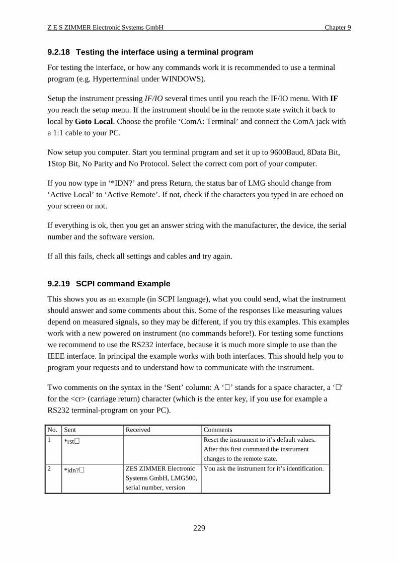
Z E S ZIMMER Electronic Systems GmbH Chapter 9
229
9.2.18 Testing the interface using a terminal progr am
For testing the interface, or how any commands work it is recommended to use a terminal
program (e.g. Hyperterminal under WINDOWS).
Setup the instrument pressing IF/IO several times until you reach the IF/IO menu. With IFyou reach the setup menu. If the instrument should be in the remote state switch it back to
local by Goto Local. Choose the profile ‘ComA: Terminal’ and connect the ComA jack with
a 1:1 cable to your PC.
Now setup you computer. Start you terminal program and set it up to 9600Baud, 8Data Bit,
1Stop Bit, No Parity and No Protocol. Select the correct com port of your computer.
If you now type in ‘*IDN?’ and press Return, the status bar of LMG should change from
‘Active Local’ to ‘Active Remote’. If not, check if the characters you typed in are echoed on
your screen or not.
If everything is ok, then you get an answer string with the manufacturer, the device, the serial
number and the software version.
If all this fails, check all settings and cables and try again.
9.2.19 SCPI command Example
This shows you as an example (in SCPI language), what you could send, what the instrument
should answer and some comments about this. Some of the responses like measuring values
depend on measured signals, so they may be different, if you try this examples. This examples
work with a new powered on instrument (no commands before!). For testing some functions
we recommend to use the RS232 interface, because it is much more simple to use than the
IEEE interface. In principal the example works with both interfaces. This should help you to
program your requests and to understand how to communicate with the instrument.
Two comments on the syntax in the ‘Sent’ column: A ‘∪’ stands for a space character, a ‘↵‘
for the <cr> (carriage return) character (which is the enter key, if you use for example a
RS232 terminal-program on your PC).
No. Sent Received Comments
1 *rst↵ Reset the instrument to it’s default values.
After this first command the instrument
changes to the remote state.
2 *idn?↵ ZES ZIMMER Electronic
Systems GmbH, LMG500,
serial number, version
You ask the instrument for it’s identification.
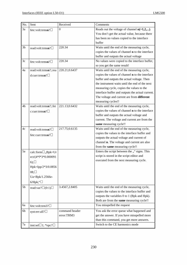
Interfaces (IEEE option L50-O1) LMG500
230
No. Sent Received Comments
3a fetc:volt:trmsn?↵ 0 Reads out the voltage of channel n(=1,2,...).You don’t get the actual value, because there
has been no values copied to the interface
buffer
3b read:volt:trmsn?↵ 220.34 Waits until the end of the measuring cycle,
copies the values of channel n to the interface
buffer and outputs the actual voltage
3c fetc:volt:trmsn?↵ 220.34 No values were copied to the interface buffer,
so you get the same result!
4a read:volt:trmsn?;:rea
d:curr:trmsn?↵220.21;0.6437 Waits until the end of the measuring cycle,
copies the values of channel n to the interface
buffer and outputs the actual voltage. Then
the instrument waits until the end of the next
measuring cycle, copies the values to the
interface buffer and outputs the actual current.
The voltage and current are from differentmeasuring cycles!!
4b read:volt:trmsn?;:fet
c:curr:trmsn?↵221.13;0.6432 Waits until the end of the measuring cycle,
copies the values of channel n to the interface
buffer and outputs the actual voltage and
current. The voltage and current are from the
same measuring cycle!!
4c read:volt:trmsn?↵fetc:curr:trmsn?↵
217.75;0.6135 Waits until the end of the measuring cycle,
copies the values to the interface buffer and
outputs the actual voltage and current of
channel n. The voltage and current are also
from the same measuring cycle!!
5a calc:form∪„Bpk=Ur
ect/(4*f*3*0.000091
6);↵Hpk=Ipp/2*3/0.0856
08;↵Ua=Bpk/1.2566e-
6/Hpk;“↵
Enters the script between the „“ signs. This
script is stored in the script editor and
executed from the next measuring cycle.
5b read:var?∪(0:1)↵ 3.4567,2.8405 Waits until the end of the measuring cycle,
copies the values to the interface buffer and
outputs the variables 0 to 1 (Bpk and Hpk).
Both are from the same measuring cycle!!
6a fetc:volt:trm3?↵ You misspelled the request
6b syst:err:all?↵ command header
error:TRM3
You ask the error queue what happened and
get the answer. If you have misspelled more
than this command, you get more answers.
7a inst:sel∪1; *opc?↵ Switch to the CE harmonics mode

Z E S ZIMMER Electronic Systems GmbH Chapter 9
231
No. Sent Received Comments
7b read:harm:curr:ampl
n?∪(3:5)↵1.2346,00034,0.9984 Waits until the end of the measuring cycle,
copies the values of channel n to the interface
buffer and outputs the amplitudes of the
current harmonics of order 3 to 5. All are
from the same measuring cycle!!
7c inst:sel∪norml;
*opc?↵
switch back to the normal measuring mode
8a trig:act;:fetc:volt:trm
s?;:fetc:pow?↵Defines that the voltage and the power should
be output after every measuring cycle, without
any further request.
8b init:cont∪on↵ 220.34;15.345
220.19;15.217
....
Activates this continuous output of the values
defined with ‘actn’. (until the CONT OFF
command!)
8c init:cont∪off↵ stops the continuous output.
9a mem:fre∪on freezes the scope memory
9b sens:wav:iupd;:sens
:wav:sbtr?∪1;:sens:
wav:satr?∪1↵
-3204, +4506 calculates new information to the sampled
values of group B (0 = group A, 1 = group B),
reads how much values are stored before and
after the trigger
9c sens:wav:wave?∪5,
(-100:100)↵220.45, 221.36 ...
(comma separated one
dimensioned array with the
size 201)
Reads out the sampled values of the voltage
9d mem:fre∪off↵ deactivates the scope memory
10 gtl Changes from the remote to the local state. So
the instrument can be controlled manually
9.2.20 SHORT command Example
This shows you as an example (in SHORT language), what you could send, what the
instrument should answer and some comments about this. Some of the responses like
measuring values depend on measured signals, so they may be different, if you try this
examples. This examples work with a new powered on instrument (no commands before!).
For testing some functions we recommend to use the RS232 interface, because it is much
more simple to use than the IEEE interface. In principal the example works with both
interfaces. This should help you to program your requests and to understand how to
communicate with the instrument.
Two comments on the syntax in the ‘Sent’ column: A ‘∪’ stands for a space character, a ‘↵‘
for the <cr> (carriage return) character (which is the enter key, if you use for example a
RS232 terminal-program on your PC).
No. Sent Received Comments
1 *rst↵ Reset the instrument to it’s default values.
After this first command the instrument
changes to the remote state.
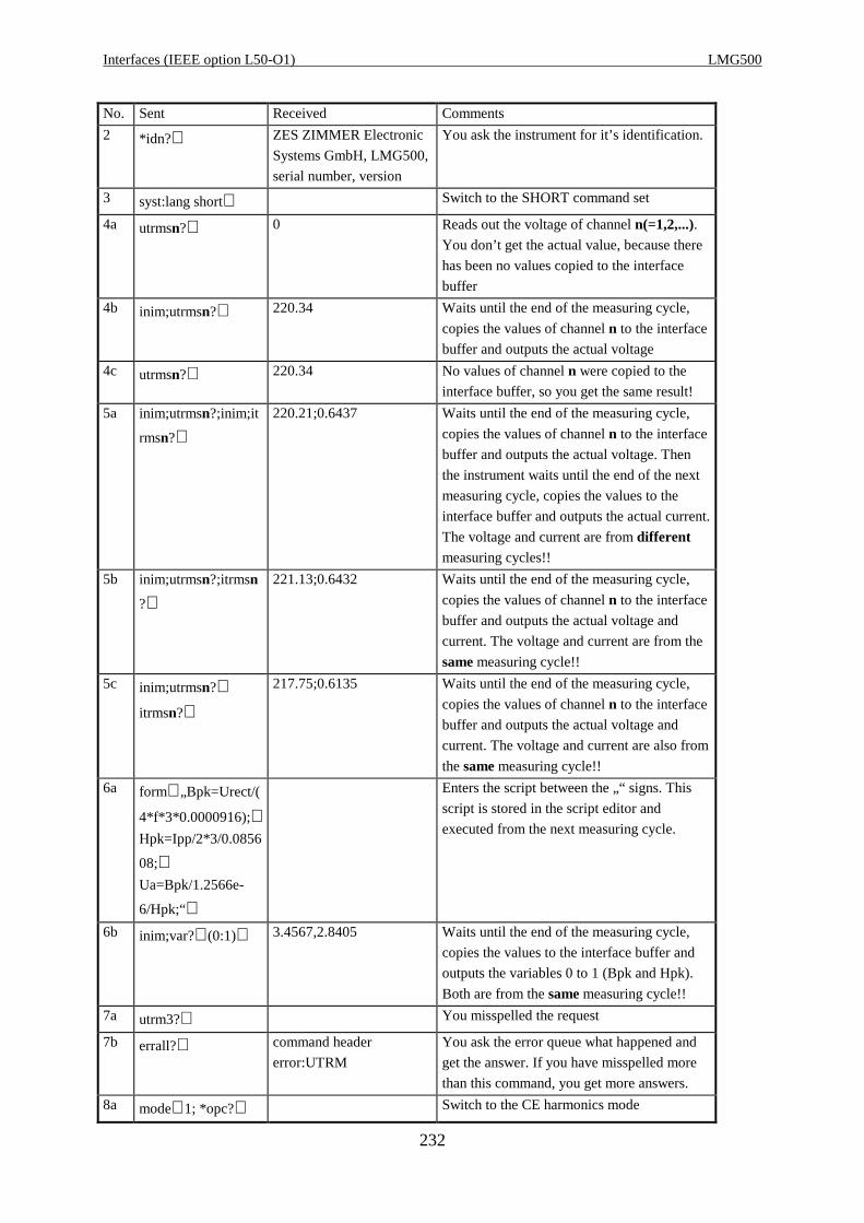
Interfaces (IEEE option L50-O1) LMG500
232
No. Sent Received Comments
2 *idn?↵ ZES ZIMMER Electronic
Systems GmbH, LMG500,
serial number, version
You ask the instrument for it’s identification.
3 syst:lang short↵ Switch to the SHORT command set
4a utrmsn?↵ 0 Reads out the voltage of channel n(=1,2,...).You don’t get the actual value, because there
has been no values copied to the interface
buffer
4b inim;utrmsn?↵ 220.34 Waits until the end of the measuring cycle,
copies the values of channel n to the interface
buffer and outputs the actual voltage
4c utrmsn?↵ 220.34 No values of channel n were copied to the
interface buffer, so you get the same result!
5a inim;utrmsn?;inim;it
rmsn?↵220.21;0.6437 Waits until the end of the measuring cycle,
copies the values of channel n to the interface
buffer and outputs the actual voltage. Then
the instrument waits until the end of the next
measuring cycle, copies the values to the
interface buffer and outputs the actual current.
The voltage and current are from differentmeasuring cycles!!
5b inim;utrmsn?;itrmsn
?↵221.13;0.6432 Waits until the end of the measuring cycle,
copies the values of channel n to the interface
buffer and outputs the actual voltage and
current. The voltage and current are from the
same measuring cycle!!
5c inim;utrmsn?↵itrmsn?↵
217.75;0.6135 Waits until the end of the measuring cycle,
copies the values of channel n to the interface
buffer and outputs the actual voltage and
current. The voltage and current are also from
the same measuring cycle!!
6a form∪„Bpk=Urect/(
4*f*3*0.0000916);↵Hpk=Ipp/2*3/0.0856
08;↵Ua=Bpk/1.2566e-
6/Hpk;“↵
Enters the script between the „“ signs. This
script is stored in the script editor and
executed from the next measuring cycle.
6b inim;var?∪(0:1)↵ 3.4567,2.8405 Waits until the end of the measuring cycle,
copies the values to the interface buffer and
outputs the variables 0 to 1 (Bpk and Hpk).
Both are from the same measuring cycle!!
7a utrm3?↵ You misspelled the request
7b errall?↵ command header
error:UTRM
You ask the error queue what happened and
get the answer. If you have misspelled more
than this command, you get more answers.
8a mode∪1; *opc?↵ Switch to the CE harmonics mode
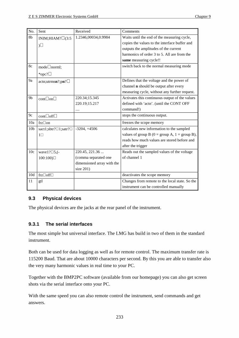
Z E S ZIMMER Electronic Systems GmbH Chapter 9
233
No. Sent Received Comments
8b INIM;HIAM? ∪(3:5
)↵
1.2346,00034,0.9984 Waits until the end of the measuring cycle,
copies the values to the interface buffer and
outputs the amplitudes of the current
harmonics of order 3 to 5. All are from the
same measuring cycle!!
8c mode∪norml;
*opc?↵
switch back to the normal measuring mode
9a actn;utrmsn?;pn?↵ Defines that the voltage and the power of
channel n should be output after every
measuring cycle, without any further request.
9b cont∪on↵ 220.34;15.345
220.19;15.217
....
Activates this continuous output of the values
defined with ‘actn’. (until the CONT OFF
command!)
9c cont∪off↵ stops the continuous output.
10a frz∪on freezes the scope memory
10b sact1;sbtr?∪1;satr?∪1↵
-3204, +4506 calculates new information to the sampled
values of group B (0 = group A, 1 = group B),
reads how much values are stored before and
after the trigger
10c wave1?∪5,(-
100:100)↵220.45, 221.36 ...
(comma separated one
dimensioned array with the
size 201)
Reads out the sampled values of the voltage
of channel 1
10d frz∪off↵ deactivates the scope memory
11 gtl Changes from remote to the local state. So the
instrument can be controlled manually
9.3 Physical devices
The physical devices are the jacks at the rear panel of the instrument.
9.3.1 The serial interfaces
The most simple but universal interface. The LMG has build in two of them in the standard
instrument.
Both can be used for data logging as well as for remote control. The maximum transfer rate is
115200 Baud. That are about 10000 characters per second. By this you are able to transfer also
the very many harmonic values in real time to your PC.
Together with the BMP2PC software (available from our homepage) you can also get screen
shots via the serial interface onto your PC.
With the same speed you can also remote control the instrument, send commands and get
answers.

Interfaces (IEEE option L50-O1) LMG500
234
9.3.1.1 ComA, RS232
In this female connector a null modem is implemented. That means if you want to connect
ComA of the LMG to a PC you have to use a cable which connects 1:1 (without a null modem
function).
Figure 41: ComA connector
Pin 1 2 3 4 5 6 7 8 9
Comment nc TxD RxD nc GND nc CTS RTS nc
9.3.1.2 ComB, RS232
In this male connector no null modem is implemented. That means if you want to connect
ComB of the LMG to a PC you have to use a cable with null modem function.
Figure 42: ComB connector
Pin 1 2 3 4 5 6 7 8 9
Comment DCD RxD TxD DTR GND DSR RTS CTS RI
9.3.2 IEEE488.2
This interface is also known as IEC625 bus or GPIB. By it you can implement the LMG into
an existing bus system.
The IEEE interface can just be used for remote control, not for logging. The maximum data
transfer is about 1 Mbytes per second. This and the connection of several other devices makes
this bus a standard for complex measuring systems
This port has the pinout defined in the standard IEEE488. You can use the standard cables.

Z E S ZIMMER Electronic Systems GmbH Chapter 9
235
9.3.3 Parallel Port
Whenever you want to print out data directly, this interface is used. In the LMG we have
implemented drivers for the most popular printers. They are just needed, if you want to print
out graphics.
Like with the serial interface you can print out cyclic values as tables.
Printers are not the fastest devices, so it can happen, that the printer gets more data than it can
handle. In this case the printing is interrupted
This port has the same pinout like a PC parallel port. You can use the same cables.


Z E S ZIMMER Electronic Systems GmbH Chapter 10
237
10 Logging of values to drives, printer and interfa ces
All menues you see can be stored to a memory card, floppy disk drives, interfaces or can be
printed out. In principal you get what you see. Some exceptions are described in the individual
chapters (e.g. you get all harmonics, not only the visible). If you want to record in single mode
you get the values you see. That means when you have frozen the display you get the frozen
values. If you are in a periodic mode then you get the actual values, also if you have frozen the
display.
The data logging is handled in a way that you have to press as few keys as possible to get the
result: To output the measured values periodically or one time to an interface or storage
media.
There are no menus where you have to choose the values you want to output. Choose just one
of the available menus and press Print/Log.
You get an dialog box where you can choose the destination of the logging (with Dest.). This
can be a file, an interface or a printer.
Each single destination entry in this menu describes an output device and its most important
setting. For storage media this is the file name, for the printer the printer type and for the
interfaces the baud rate. This and other settings you can change at any time by pressing Set.Your changes are stored in so called ‘profiles’. This profiles are stored in the memory. They
are just valid in their environment: If you change the baud rate of ComA for logging, the baud
rate of ComA for remote control is not changed!
In the dialog box you see further on the state of the chosen destination device. For storage
media you see here also the available size and the number of stored files. For printers you can
get ‘printer ready’, ‘printer busy’ or ‘paper empty’.
10.1 Start of logging
The logging itself starts, if you close the dialog box with Enter. (if you press Esc you close the
box without storing). In the status bar you get at the right side a red/green flashing log display
while the logging is active.
If you want to output to a serial interface it could happen, that this interface is already reserved
for remote control. In this case you are asked, if you want to change the usage of this interface
from remote control to logging. If you say 'Yes' the usage is changed. Please make sure, that
you don’t have any remote controlled data transfer before you press Enter.
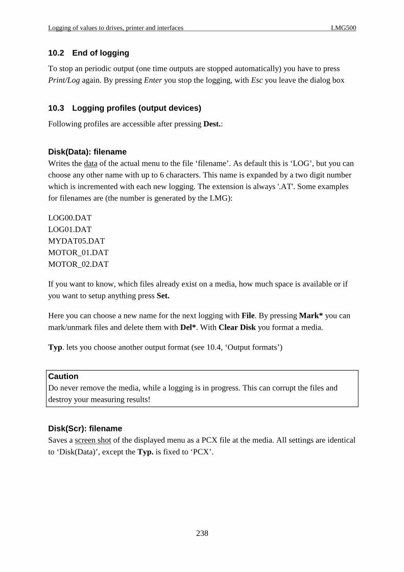
Logging of values to drives, printer and interfaces LMG500
238
10.2 End of logging
To stop an periodic output (one time outputs are stopped automatically) you have to press
Print/Log again. By pressing Enter you stop the logging, with Esc you leave the dialog box
10.3 Logging profiles (output devices)
Following profiles are accessible after pressing Dest.:
Disk(Data): filenameWrites the data of the actual menu to the file ‘filename’. As default this is ‘LOG’, but you can
choose any other name with up to 6 characters. This name is expanded by a two digit number
which is incremented with each new logging. The extension is always '.AT'. Some examples
for filenames are (the number is generated by the LMG):
LOG00.DAT
LOG01.DAT
MYDAT05.DAT
MOTOR_01.DAT
MOTOR_02.DAT
If you want to know, which files already exist on a media, how much space is available or if
you want to setup anything press Set.
Here you can choose a new name for the next logging with File. By pressing Mark* you can
mark/unmark files and delete them with Del*. With Clear Disk you format a media.
Typ. lets you choose another output format (see 10.4, ‘Output formats’)
CautionDo never remove the media, while a logging is in progress. This can corrupt the files and
destroy your measuring results!
Disk(Scr): filenameSaves a screen shot of the displayed menu as a PCX file at the media. All settings are identical
to ‘Disk(Data)’, except the Typ. is fixed to ‘PCX’.

Z E S ZIMMER Electronic Systems GmbH Chapter 10
239
ComA: baudrateThe measuring values are transferred in the chosen ‘Output as’ format via ComA with the
displayed baud rate. With Set you can change baud rate, protocol or the format. For the
connection to the PC you have to use a 1:1 cable.
ComB: baudrateSame like ‘ComA: baudrate’, but another jack and you have to use a null-modem cable.
ComA: BMP2PCIf you don’t have a storage media but want to get screen shots, you can use this profile. Use
our program BMP2PC (available on our homepage www.zes.com) and connect your PC with
a 1:1 cable with ComA. Then you can transfer a screen shot to the PC and the receiving
program stores it as a bitmap file.
Lpt: printerOn a connected printer you can output measuring values as well as hardcopies of the actual
screen. The 'output as displayed' is pure text, so that you can connect almost every printer. For
a graphical output you have to setup the correct printer type. Due to the growing number of
printers it’s not possible to write a driver for each type. So we implemented 5 generic drivers
which can drive most available printers:
EPSON 9-Pin
EPSON ESP/P
EPSON ESP/P2
HP DeskJet
HP LaserJet
In case of any doubts please contact your local computer shop.
After pressing Set you can setup the model (Prn) and the output format (Output as). Further
on you can create a comment (Rem) which is also printed (see 10.5, ‘Remarks, header lines’).
Some models try to get a complete image of a page in their RAM before they start printing.
Therefore you might think, the printer is not working, if you send it just some few lines.
It’s not a good idea to output a page after just few lines. Therefore we send as default no form
feed to the printer. But you can change this with At end: instead of 'None' setup 'paper out'. Or
you can press Page out to do this manually, when you like.
10.3.1 Output intervals
With Mode you can setup how often the values should be output:
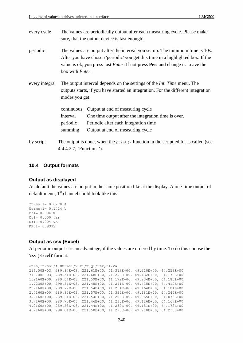
Logging of values to drives, printer and interfaces LMG500
240
every cycle The values are periodically output after each measuring cycle. Please make
sure, that the output device is fast enough!
periodic The values are output after the interval you set up. The minimum time is 10s.
After you have chosen 'periodic' you get this time in a highlighted box. If the
value is ok, you press just Enter. If not press Per. and change it. Leave the
box with Enter.
every integral The output interval depends on the settings of the Int. Time menu. The
outputs starts, if you have started an integration. For the different integration
modes you get:
continuous Output at end of measuring cycle
interval One time output after the integration time is over.
periodic Periodic after each integration time
summing Output at end of measuring cycle
by script The output is done, when the print() function in the script editor is called (see
4.4.4.2.7, ‘Functions’).
10.4 Output formats
Output as displayedAs default the values are output in the same position like at the display. A one-time output of
default menu, 1st channel could look like this:
Itrms:1= 0.0270 AUtrms:1= 0.1414 VP:1=-0.004 WQ:1= 0.000 varS:1= 0.004 VAPF:1= 0.9992
Output as csv (Excel)At periodic output it is an advantage, if the values are ordered by time. To do this choose the
'csv (Excel)' format.
dt/s,Itrms1/A,Utrms1/V,P1/W,Q1/var,S1/VA216.00E-03, 289.94E-03, 221.61E+00, 41.313E+00, 49.210E+00, 64.253E+00716.00E-03, 289.51E-03, 221.68E+00, 41.290E+00, 49.132E+00, 64.178E+001.2160E+00, 289.64E-03, 221.59E+00, 41.172E+00, 49.234E+00, 64.180E+001.7230E+00, 290.86E-03, 221.45E+00, 41.291E+00, 49.435E+00, 64.410E+002.2160E+00, 289.72E-03, 221.54E+00, 41.261E+00, 49.164E+00, 64.184E+002.7160E+00, 289.95E-03, 221.57E+00, 41.335E+00, 49.181E+00, 64.245E+003.2160E+00, 289.21E-03, 221.54E+00, 41.206E+00, 49.065E+00, 64.073E+003.7160E+00, 289.75E-03, 221.46E+00, 41.280E+00, 49.126E+00, 64.167E+004.2160E+00, 289.83E-03, 221.44E+00, 41.232E+00, 49.181E+00, 64.178E+004.7160E+00, 290.01E-03, 221.50E+00, 41.290E+00, 49.210E+00, 64.238E+00
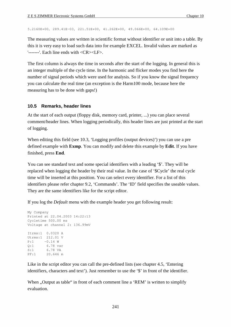
Z E S ZIMMER Electronic Systems GmbH Chapter 10
241
5.2160E+00, 289.41E-03, 221.51E+00, 41.262E+00, 49.066E+00, 64.109E+00
The measuring values are written in scientific format without identifier or unit into a table. By
this it is very easy to load such data into for example EXCEL. Invalid values are marked as
'-------'. Each line ends with <CR><LF>.
The first column is always the time in seconds after the start of the logging. In general this is
an integer multiple of the cycle time. In the harmonic and flicker modes you find here the
number of signal periods which were used for analysis. So if you know the signal frequency
you can calculate the real time (an exception is the Harm100 mode, because here the
measuring has to be done with gaps!)
10.5 Remarks, header lines
At the start of each output (floppy disk, memory card, printer, ...) you can place several
comment/header lines. When logging periodically, this header lines are just printed at the start
of logging.
When editing this field (see 10.3, ‘Logging profiles (output devices)’) you can use a pre
defined example with Exmp. You can modify and delete this example by Edit . If you have
finished, press End.
You can see standard text and some special identifiers with a leading ‘$’. They will be
replaced when logging the header by their real value. In the case of ‘$Cycle’ the real cycle
time will be inserted at this position. You can select every identifier. For a list of this
identifiers please refer chapter 9.2, ‘Commands’. The ‘ID’ field specifies the useable values.
They are the same identifiers like for the script editor.
If you log the Default menu with the example header you get following result:
My CompanyPrinted at 22.04.2003 14:22:13Cycletime 500.00 msVoltage at channel 2: 136.99mV
Itrms:1 0.0320 AUtrms:1 212.01 VP:1 -0.14 WQ:1 6.78 varS:1 6.78 VAPF:1 20.646 m
Like in the script editor you can call the pre-defined lists (see chapter 4.5, ‘Entering
identifiers, characters and text’). Just remember to use the ‘$’ in front of the identifier.
When „Output as table“ in front of each comment line a ‘REM’ is written to simplify
evaluation.

Logging of values to drives, printer and interfaces LMG500
242
10.6 Storage media
Storage media are used to store single or periodic measuring data. The data format is equal to
the data format of the serial or parallel interface. But this data are written immediately and
evaluated later on.
Equivalent to a screen dump to a printer you can make a screen shot and store it in the popular
PCX file format.
10.6.1 Floppy disk drive
The optional floppy disk drive is a PC compatible 3 1/2“ drive for 1.44 Mbytes disks.
The file format is MSDOS (FAT) format. So you can read it with each PC with an Microsoft
OS.
Floppy disk is a very good medium for data transfer to a PC if you want to evaluate the
measured data afterwards. The disadvantage is the slow data transfer and the medium storage
capacity. The medium transfer rate is just about 20kbyte per second, if you use a blank,
formatted disk.
If you want to store harmonic values you get about 100 harmonics for 4 channels for each
measuring cycle. That are 400 values which take about 5000 characters in storage. At 200ms
cycle time you have about 25kbyte per second! In this case it might be better to use a memory
card drive.
10.6.2 USB memory stick
The number of files and directories in the root directory must not be more than 150. Else you
get the error message „File Table Overflow“.
The stick must be formatted with FAT16. FAT32 will not work! The stick must not contain
any own operating system (like e.g. Titanium Cruzer). Such an OS must be removed before
the usage. The stick must not have more than one partition.
After calling the log dialog it can take several seconds until the structure of the memory stick
is analysed. The time increases, if more files or stored on the stick. If the log dialog is opened,
the stick must not be removed.
The stick implementation does not support a real formatting of the stick. So if you choose
formatting, only the files in the root directory are delete. This can take several seconds. For a
real formatting, please use a PC.

Z E S ZIMMER Electronic Systems GmbH Chapter 10
243
10.7 Import of data into PC programs
To get the measuring values into your PC you have two possibilities: You can store them on a
storage media or you can send them via the serial interface.
10.7.1 Data exchange via storage media
If you are using a floppy disk it is no problem if you have a standard floppy disk drive.
10.7.2 Data exchange via serial interface
For this you just need a 1:1 cable (or a null modem cable if you are using ComB) and an
installed terminal program. On each Windows PC you should have the program ‘Hyperterm’
already installed.
1. Start Hyperterm and enter any name for the new connection.
2. Choose the COM port which is connected to your PC.
3. Set up this port with following parameters:
Baud rate 115200
Databits 8
Parity None
Stopbits 1
Protocol None
4. Hyperterm is now ready to receive data. To test the connection press Print/Log at LMG,
choose ‘ComA: 115200’ as destination. If the baud rate should not be 115200 please set it
via Set. If you are using ComB do the same for it..
The mode should be set to 'one-time' and ‘output as table’.
5. Press Enter to start the transfer.
6. Hyperterm should now display the values. If not, check the correct ports, cable and all
settings. Check also that Hyperterm is ‘on-line’. If not, open the connection.
7. Hyperterm receives correct data. You can save the following data into a file via menu
‘transfer’ and ‘save text’
8. Press at LMG Print/Log again and choose now 'every cycle'. Start logging with Enter.
In Hyperterm you see now the received data which are stored in background.
9. To stop the logging press Print/Log and Enter.
10. Stop the recording of Hyperterm by closing the text file. If you open this file with any text
editor you see the logged data.
10.7.3 Country dependent numbers
Float numbers are output with a dot '.' as decimal separator. This can cause problems, when
your computer is set up to use ‘,’ as separator (like for example in Germany). In this case set
up your operating system to use the dot ‘.’ as separator.

Logging of values to drives, printer and interfaces LMG500
244
10.7.4 Reading data into EXCEL
First make sure, that the decimal separator is set up correctly. Then start Excel and load the
file. Choose the number of lines Excel should skip to reject the header.
As column separator select a space.
Now the data from the file are read into Excel without any problems.
10.8 Error messages
Drive not readyYou have chosen a storage media as destination, but this media is not plugged in. Press Esc
until the message vanishes. Choose another destination or insert the storage media
Operation not permittedAn error occurred while storing. For example the storage media was removed.
Output device too slow - stopped!The chosen output device is too slow to handle the data in real time. In this case the logging is
stopped. Press Esc until the message vanishes. Choose a faster output device or reduce the
data volume for example by choosing a longer cycle time.
All values until this message are stored correctly.
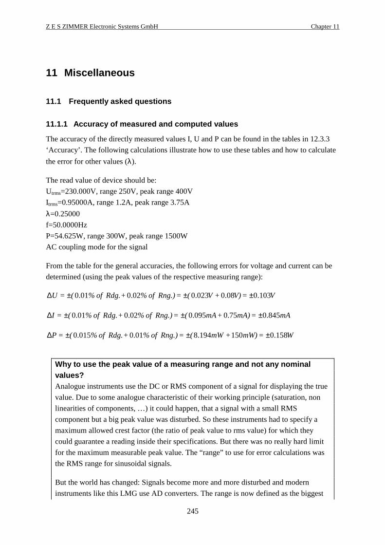
Z E S ZIMMER Electronic Systems GmbH Chapter 11
245
11 Miscellaneous
11.1 Frequently asked questions
11.1.1 Accuracy of measured and computed values
The accuracy of the directly measured values I, U and P can be found in the tables in 12.3.3
‘Accuracy’. The following calculations illustrate how to use these tables and how to calculate
the error for other values (λ).
The read value of device should be:
Utrms=230.000V, range 250V, peak range 400V
Itrms=0.95000A, range 1.2A, peak range 3.75A
λ=0.25000
f=50.0000Hz
P=54.625W, range 300W, peak range 1500W
AC coupling mode for the signal
From the table for the general accuracies, the following errors for voltage and current can be
determined (using the peak values of the respective measuring range):
V=V)+V(=Rng.) of %+Rdg. of %(=U 103.008.0023.002.001.0 ±±±∆
mA=mA)+mA(=Rng.) of %+Rdg. of %(=I 845.075.0095.002.001.0 ±±±∆
W=mW)+mW(=Rng.) of %+Rdg. of %(=P 158.0150194.801.0015.0 ±±±∆
Why to use the peak value of a measuring range and not any nominalvalues?Analogue instruments use the DC or RMS component of a signal for displaying the true
value. Due to some analogue characteristic of their working principle (saturation, non
linearities of components, …) it could happen, that a signal with a small RMS
component but a big peak value was disturbed. So these instruments had to specify a
maximum allowed crest factor (the ratio of peak value to rms value) for which they
could guarantee a reading inside their specifications. But there was no really hard limit
for the maximum measurable peak value. The “range” to use for error calculations was
the RMS range for sinusoidal signals.
But the world has changed: Signals become more and more disturbed and modern
instruments like this LMG use AD converters. The range is now defined as the biggest
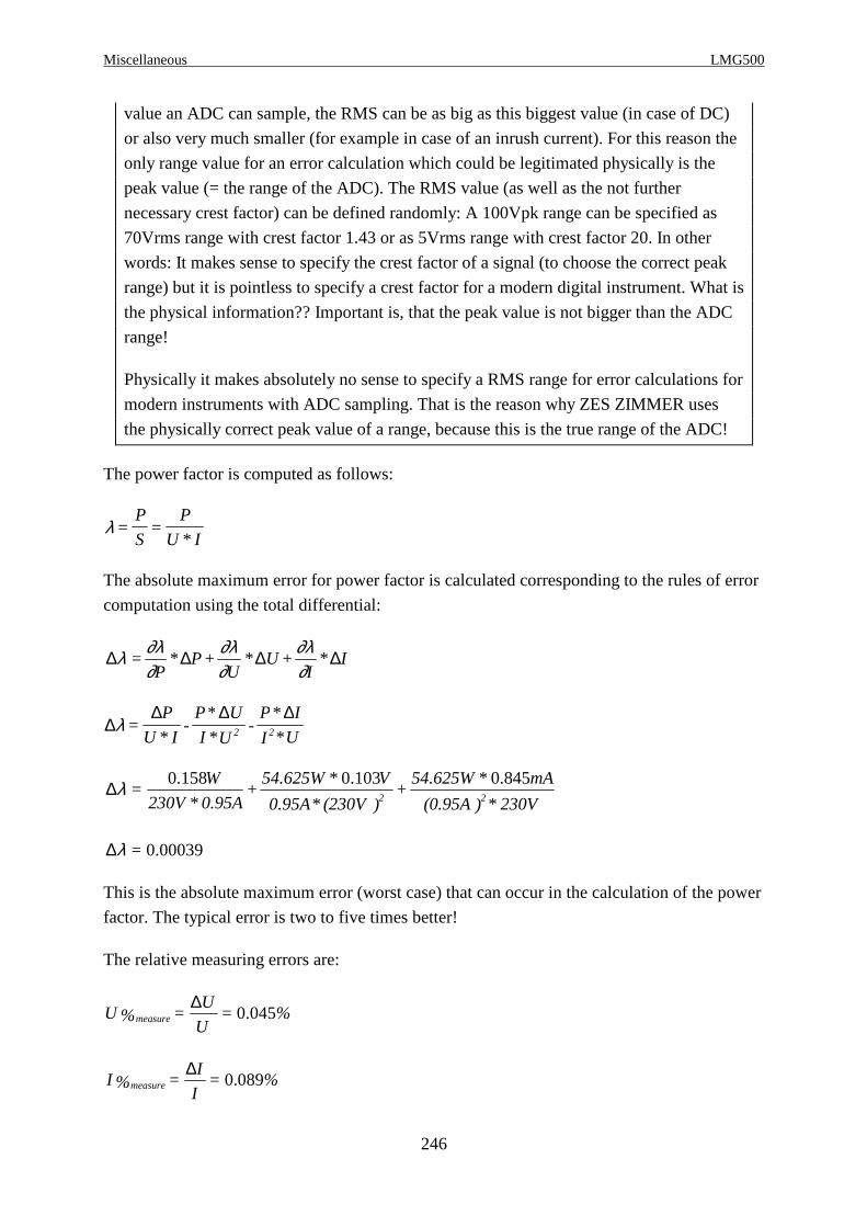
Miscellaneous LMG500
246
value an ADC can sample, the RMS can be as big as this biggest value (in case of DC)
or also very much smaller (for example in case of an inrush current). For this reason the
only range value for an error calculation which could be legitimated physically is the
peak value (= the range of the ADC). The RMS value (as well as the not further
necessary crest factor) can be defined randomly: A 100Vpk range can be specified as
70Vrms range with crest factor 1.43 or as 5Vrms range with crest factor 20. In other
words: It makes sense to specify the crest factor of a signal (to choose the correct peak
range) but it is pointless to specify a crest factor for a modern digital instrument. What is
the physical information?? Important is, that the peak value is not bigger than the ADC
range!
Physically it makes absolutely no sense to specify a RMS range for error calculations for
modern instruments with ADC sampling. That is the reason why ZES ZIMMER uses
the physically correct peak value of a range, because this is the true range of the ADC!
The power factor is computed as follows:
λ =P
S=
P
U * I
The absolute maximum error for power factor is calculated corresponding to the rules of error
computation using the total differential:
∆ ∆ ∆ ∆λ ∂λ∂
∂λ∂
∂λ∂
=P
* P+U
* U +I
* I
∆∆ ∆ ∆
λ =P
U * I-
P* U
I *U-
P* I
I *U2 2
230V*)(0.95A
mA*54.625W+
)(230V*0.95A
V*54.625W+
0.95A*230V
W=
22
845.0103.0158.0λ∆
00039.0=λ∆
This is the absolute maximum error (worst case) that can occur in the calculation of the power
factor. The typical error is two to five times better!
The relative measuring errors are:
%=U
U=%U measure 045.0
∆
%=I
I=%I measure 089.0
∆
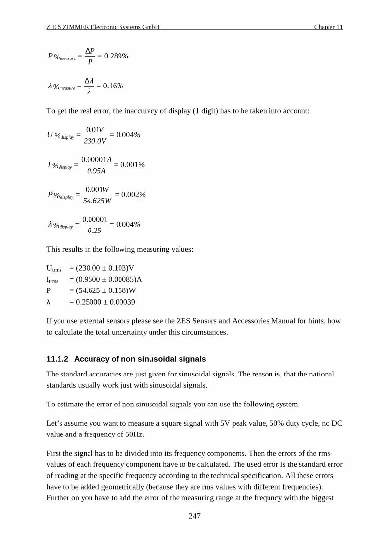
Z E S ZIMMER Electronic Systems GmbH Chapter 11
247
%=P
P=%P measure 289.0
∆
%==%measure 16.0λλλ ∆
To get the real error, the inaccuracy of display (1 digit) has to be taken into account:
%=230.0V
V=%U display 004.0
01.0
%=0.95A
A=%I display 001.0
00001.0
%=54.625W
W=%P display 002.0
001.0
%=0.25
=%display 004.000001.0λ
This results in the following measuring values:
Utrms = (230.00 ± 0.103)V
Itrms = (0.9500 ± 0.00085)A
P = (54.625 ± 0.158)W
λ = 0.25000 ± 0.00039
If you use external sensors please see the ZES Sensors and Accessories Manual for hints, how
to calculate the total uncertainty under this circumstances.
11.1.2 Accuracy of non sinusoidal signals
The standard accuracies are just given for sinusoidal signals. The reason is, that the national
standards usually work just with sinusoidal signals.
To estimate the error of non sinusoidal signals you can use the following system.
Let’s assume you want to measure a square signal with 5V peak value, 50% duty cycle, no DC
value and a frequency of 50Hz.
First the signal has to be divided into its frequency components. Then the errors of the rms-
values of each frequency component have to be calculated. The used error is the standard error
of reading at the specific frequency according to the technical specification. All these errors
have to be added geometrically (because they are rms values with different frequencies).
Further on you have to add the error of the measuring range at the frequncy with the biggest

Miscellaneous LMG500
248
amplitude (usually the fundamental) once (once because it includes common errors like offset,
...). With this sum you can calculate the total error.
The values in the columns of the following table are:
Frequency (f / Hz)
rms value at this frequency (U / V)
Percentage error of frequency component according to technical data (% of value)
• Absolute error of frequency component (∆U / mV)
f / Hz U / V Error in % of U Error ∆U / mV
50 4.501 0.01 0.4501
150 1.500 0.02 0.3000
250 0.900 0.02 0.1800
350 0.636 0.02 0.1272
450 0.499 0.02 0.0998
550 0.408 0.02 0.0816
650 0.346 0.02 0.0692
750 0.300 0.02 0.0600
For this example only the harmonics from 1 (50Hz) to 15 (750Hz) have been used. Harmonics
of a higher order cause just barely greater errors not affecting the total error very much like
shown in the table.
The geometrical sum of all errors results in an error of 0.6051mV.
To that you have to add the error of the range (0.02% of 12V (peak-value) = 2.4mV).
The total error is 3.0051mV which is 0.06% of 5V.
11.1.3 Hints for setting up the record rate of the scope
The scope function defines the record rate of the sample values indirectly by changing the
timebase. When transferring sample values over the interface it is more useful to setup a fix
record rate instead of setting up a timebase. The relation between timebase and record rate is
described here.
The CAPITAL words are not requestable via interface nor visible on the display. They are
here locally introduced to explain the situation.

Z E S ZIMMER Electronic Systems GmbH Chapter 11
249
Scope settingsBASE The only setting for the scope is the timebase, i.e. the time per division in seconds.
There are 20 sample values per division used. The timebase can be set in a range
from 10µs to 1s in a 1-2-5 stepping.
Software parametersCYCLE The cycle time in seconds.
DIV This is the sample rate pre divider which depends on the selected filter. The
following values are possible:
1 without filter
2 with filter > 10 kHz
30 with filter ≤ 10 kHz
For the calculation the biggest divider of all groups is used. Example: Group A
without filter, group B with 270kHz Filter, group C with 10kHz filter. Then
DIV=30 is used.
SMPL sampling rate
SMPL = 3MS/s / DIV
Hardware parametersMEM Memory depth: This is always 1048576. In master slave mode the memory is
doubled, but there are also more channels, so this values is constant. See CHNS.
CHNS Number of power measuring channels. In master slave mode, CHNS is the
maximum number of channels in each single instrument. Example: Master has 4,
slave 3 channels. Then CHNS=4 is used.
Internal parametersZOOM The display of the values depends on the ZOOM factor. It defines, how many
sample values are packed to one display value. The default value is 10. The
parameter ZOOM is changed, if BASE becomes such small, that the requested
display can only be reached by reducing ZOOM. In this case not 10 values are
packed but less, down to 1. ZOOM can only be 50, 20, 10, 5, 2, 1. With ZOOM=1
every sampled value is stored and displayed. Over the interface you will get every
stored value, independent of the ZOOM setting. For the calculation of this value,
see below.
FREEZE If the memory is frozen, of course you can’t change the sample rate any more.
Changing BASE can now only influence the ZOOM value to zoom in or out. Due to

Miscellaneous LMG500
250
the limited value range of ZOOM, the zooming is also limited. For the influence of
this parameter see below.
ResultsFollowing interim values are calculated
RATE Storage rate
RATE = 20 * ZOOM / BASE
DUR Storage duration
DUR = MEM / CHNS / RATE
If a special sampling rate is wished, it can be calculated in opposite order:
BASE =20 * ZOOM / RATE
Caution:Not every storage rate is possible. By rounding (dividers must always be integers!)
and internal divider structures the resulting storage rate can be different from the
requested one. It is always necessary to check the storage rate by the GFRQ interface
command.
Example: 4 channels, BASE = 10ms/div, ZOOM = 10.
RATE = 20000 samples/s
DUR = 13.11s
LimitsMAXRATE The maximum storage rate. It is limited by the cycle time (CYCLE) and the
number of channels (CHNS). Because at least one complete cycle of all channels
has to fit into the memory. For administrative purposes the cycle time must be
multiplied with a factor of 1.7!
MAXRATE = MEM / (CYCLE * 1.7 * CHNS)
If MAXRATE is bigger than SMPL then MAXRATE = SMPL!
Example 1: CYCLE = 0.5s, 4 CHNS
MAXRATE = 308,457 kS/s (only 200kS/s settable, see MINBASE)
Example 2: CYCLE = 0.05s, 4 CHNS
MAXRATE = 3.08MS/s (limited to 3MS/s!)
This shows, that the maximum sample rate is possible with 4 channels at fastest
cycle time.
From above calculation for BASE you get a minimum timebase MINBASE at ZOOM=1 and
with the maximum storage rate MAXRATE:

Z E S ZIMMER Electronic Systems GmbH Chapter 11
251
MINBASE = 20 * ZOOM / MAXRATE = 20 / MAXRATE
Example: CYCLE = 0.5, 4 CHNS
MINBASE = 64µs.
The next bigger valid value is 100µs which results in a real RATE of
RATE = 20 * ZOOM / BASE = 20kS/s (see above).
The third limit is a divider. The ration SMPL / RATE must be an integer. If it is not, the
resulting number must be scaled down and SMPL must be divided by it to get the real RATE.
Determination of ZOOMWithout Freeze
If you reduce BASE, ZOOM stays at 10 as long as the storage RATE is much smaller than
MAXRATE. If it becomes bigger, ZOOM must be reduced to reach a valid rate (see definition
of RATE).
For MAXRATE / RATE ≥ 10 you get ZOOM = 10
For 5 < MAXRATE / RATE < 10 you get ZOOM = 5
For 2 < MAXRATE / RATE < 5 you get ZOOM = 2
For MAXRATE / RATE < 2 you get ZOOM = 1
With Freeze
If Freeze was pressed the actual BASE is stored as LASTBASE. In the same way ZOOM is
stored as LASTZOOM.
The zoom factor is now:
ZOOM = BASE * LASTZOOM / LASTBASE
in the range from 1 to 50. In this case ZOOM has no 1-2-5 stepping, because this comes
indirectly from the stepped input of BASE!
Validity of BASEIf the calculated value for ZOOM is outside the range 1-50, the setting of BASE becomes
invalid. In this case there is an error message in the display or in the interface system.
Calculation of BASE for a requested sampling rateZOOM is always 1, because via interface you can’t zoom, i.e. you always get all sample
values!
Example 1
Miscellaneous LMG500
252
You have a 3 phase instrument and want a sampling rate of 150kS/s without any filter and a 1s
cycle time. How to setup BASE?
BASE =20 * ZOOM / RATE. So you get BASE = 133µs/div, the next valid stepped
neighbours are 100µs/div and 200µs/div. This results in a real rate of 100kS/s @ 200µs/div
and 200kS/s @ 100µs/div.
Now we have to check the limits:
MAXRATE = MEM / (CYCLE * 1.7 * CHNS) = 205603kS/s
MINBASE = 20 / MAXRATE = 0.97ms/div
SMPL / RATE = 30 resp. 15
Both BASE settings would meet these conditions! You can’t setup 150kS/s as sampling rate
but 100kS/s or 200kS/s.
Example 2
You have a 3 phase instrument and want a sampling rate of 150kS/s with 9.2kHz filter and a
1s cycle time. How to setup BASE?
BASE =20 * ZOOM / RATE. So you get BASE = 133µs/div, the next valid stepped
neighbours are 100µs/div and 200µs/div. This results in a real rate of 100kS/s @ 200µs/div
and 200kS/s @ 100µs/div.
Now we have to check the limits:
MAXRATE = MEM / (CYCLE * 1.7 * CHNS) / DIV = 205603kS/s
MAXRATE is limited to 100kS/s due to the filter setting! So the 100µs/div is not possible to
setup!
MINBASE = 20 / MAXRATE = 200µs/div
SMPL / RATE = 1
The 200µs/div BASE setting meets all conditions and is possible, so the best possible
sampling rate is 100kS/s.
Example 3
You have a 3 phase instrument and want a sampling rate of 3MS/s without filter and a 0.05s
cycle time. How to setup BASE?
BASE =20 * ZOOM / RATE. So you get BASE = 6.7µs/div, the next valid stepped
neighbours are 5µs/div and 10µs/div. The smallest possible value is 10µs/div, so the other
value doesn’t matter. This results in a RATE of 2MS/s @ 10µs/div.
Now we have to check the limits:

Z E S ZIMMER Electronic Systems GmbH Chapter 11
253
MAXRATE = MEM / (CYCLE * 1.7 * CHNS) / DIV = 4112063S/s
MAXRATE is limited to 3MS/s due to the filter setting.
MINBASE = 20 / MAXRATE = 6.7µs/div
SMPL / RATE = 1.5, scaled down to 1.0, resulting in a new RATE = 3MS/s / 1 = 3MS/s.
The 10µs/div BASE setting meets all conditions and is possible, so the best possible sampling
rate is 3MS/s.
11.2 Function fault
If you think you have found an error or function fault in a LMG500 please fill out the
following page and send it to ZES. If you think the measuring result are wrong, please also fill
out the second page. For this purpose connect the measuring circuit, freeze the screen with the
values and fill out the paper with the frozen values.
On the attached CD you find a tool called ‘LMG CONTROL’. One feature of this tool is, that
it can store all measuring values and a complete configuration in a report file. You can also
use this tool to generate a function fault report.
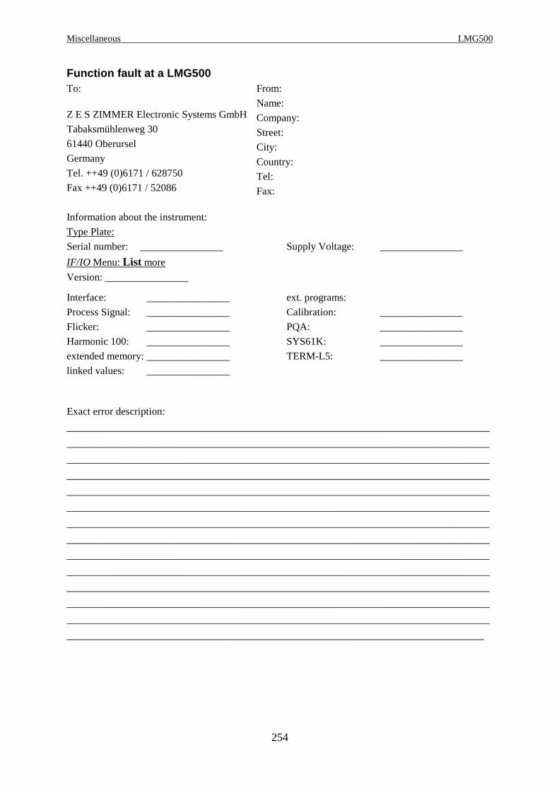
Miscellaneous LMG500
254
Function fault at a LMG500To:
Z E S ZIMMER Electronic Systems GmbH
Tabaksmühlenweg 30
61440 Oberursel
Germany
Tel. ++49 (0)6171 / 628750
Fax ++49 (0)6171 / 52086
From:
Name:
Company:
Street:
City:
Country:
Tel:
Fax:
Information about the instrument:
Type Plate:
Serial number: ________________ Supply Voltage: ________________
IF/IO Menu: List more
Version: ________________
Interface: ________________ ext. programs:
Process Signal: ________________ Calibration: ________________
Flicker: ________________ PQA: ________________
Harmonic 100: ________________ SYS61K: ________________
extended memory: ________________ TERM-L5: ________________
linked values: ________________
Exact error description:
___________________________________________________________________________
___________________________________________________________________________
___________________________________________________________________________
___________________________________________________________________________
___________________________________________________________________________
___________________________________________________________________________
___________________________________________________________________________
___________________________________________________________________________
___________________________________________________________________________
___________________________________________________________________________
___________________________________________________________________________
___________________________________________________________________________
___________________________________________________________________________
__________________________________________________________________________

Z E S ZIMMER Electronic Systems GmbH Chapter 11
255
Measuring menu
GlobalsCycle: ________ Aver: ________ Wiring: _____________
Group AFilter: ________ S_Cpl: ________Signal ________ Demod: ________HP: ________ LP: ________
Group BFilter: ________ S_Cpl: ________Signal ________ Demod: ________HP: ________ LP: ________
Channel 1
Range menuU jack: ________ I jack: ________U range: ________V I range: ________AU range: auto/manual I range: auto/manualU scale: ________ I scale: ________Sensor-Types, SN: ________________________
Voltage menu Current menu Power menuUtrms: ________ Itrms: ________ P: ________Uac: ________ Iac: ________ Q: ________Udc: ________ Idc: ________ S: ________Upp: ________ Ipp: ________ PF: ________Upkp: ________ Ipkp: ________ f: ________Upkn: ________ Ipkn: ________ Z: ________Urect: ________ Irect: ________ Rser: ________Ucf: ________ Icf: ________ Xser: ________Uff: ________ Iff: ________
Iinr: ________
Channel 2
Range menuU jack: ________ I jack: ________U range: ________V I range: ________AU range: auto/manual I range: auto/manualU scale: ________ I scale: ________Sensor-Types, SN: ________________________

Miscellaneous LMG500
256
Voltage menu Current menu Power menuUtrms: ________ Itrms: ________ P: ________Uac: ________ Iac: ________ Q: ________Udc: ________ Idc: ________ S: ________Upp: ________ Ipp: ________ PF: ________Upkp: ________ Ipkp: ________ f: ________Upkn: ________ Ipkn: ________ Z: ________Urect: ________ Irect: ________ Rser: ________Ucf: ________ Icf: ________ Xser: ________Uff: ________ Iff: ________
Iinr: ________
Channel 3
Range menuU jack: ________ I jack: ________U range: ________V I range: ________AU range: auto/manual I range: auto/manualU scale: ________ I scale: ________Sensor-Types, SN: ________________________
Voltage menu Current menu Power menuUtrms: ________ Itrms: ________ P: ________Uac: ________ Iac: ________ Q: ________Udc: ________ Idc: ________ S: ________Upp: ________ Ipp: ________ PF: ________Upkp: ________ Ipkp: ________ f: ________Upkn: ________ Ipkn: ________ Z: ________Urect: ________ Irect: ________ Rser: ________Ucf: ________ Icf: ________ Xser: ________Uff: ________ Iff: ________
Iinr: ________
Channel 4
Range menuU jack: ________ I jack: ________U range: ________V I range: ________AU range: auto/manual I range: auto/manualU scale: ________ I scale: ________Sensor-Types, SN: ________________________
Voltage menu Current menu Power menuUtrms: ________ Itrms: ________ P: ________Uac: ________ Iac: ________ Q: ________Udc: ________ Idc: ________ S: ________Upp: ________ Ipp: ________ PF: ________

Z E S ZIMMER Electronic Systems GmbH Chapter 11
257
Upkp: ________ Ipkp: ________ f: ________Upkn: ________ Ipkn: ________ Z: ________Urect: ________ Irect: ________ Rser: ________Ucf: ________ Icf: ________ Xser: ________Uff: ________ Iff: ________
Iinr: ________
You can directly print out this menus.
Please sketch also the wiring of LMG500 and equipment under test / measuring signals:

Miscellaneous LMG500
258
11.3 Maintenance
11.3.1 Calibration
With this precision power meter you have a high end measuring instrument. But you can only
take advantage of it’s performance, if the instrument is well adjusted and calibrated.
Especially with the calibration of third party labs there are very often unnecessary problems. If
you let the calibration made by any third party calibration lab, please watch following points:
• The reference instruments might have not the required accuracy, especially for active AC
power.
A very common error is, that reference sources, which some companies call ‘calibrator’
have not the necessary accuracy to calibrate this instrument. The calibrators are very
useful for many hand held multimeters, but are often worthless when calibrating active
power. A common candidate for this error is the Fluke 5500A calibrator.
Please keep in mind, that the reference instrument should be at least 3 times more accurate
than the device under test. If not, the precision power meter calibrates the so called
calibrator!
• The reference instrument may be traceable for voltage and current, but it is very rare, that
it is traceable for active AC power with the required accuracy. Nevertheless it is common,
that calibration labs calibrate active power if only voltage and current are traceable. This
happens very often in the context of national calibration services like DKD, UKAS, …
Here it happens regular, that voltage and current are accredited, but not the active power.
So this protocols are worthless for active power!
If a calibration is performed by any third party lab, at least following points should be
calibrated to ensure a proper function of the instrument:
• Voltage and current of all ranges at a frequency near to 50Hz.
• A representative selection of voltage/current range combinations to ensure a proper power
reading
The ZES ZIMMER calibration service offers a traceable calibration of all relevant parameters
and meets the requirements of IEC17025. Our active power calibration is directly traceable to
PTB (Physikalisch Technische Bundesanstalt in Braunschweig).
A further advantage of our calibration service is, that for the case of a service there are no
additional shipping costs and time delays.
Z E S ZIMMER Electronic Systems GmbH Chapter 11
259
11.3.1.1 Requirements for reference instruments
As generally known the references, calibration sources and/or reference power meters, have to
be in an accuracy class, which is at least 3 time better than the LMG500. An optimal value is
from 5 to 10 times better.
For the allowed error of the LMG to be calibrated please refer also to chapter 11.1.1,
‘Accuracy of measured and computed values’
11.3.2 Adjustment
The adjustment has to be done at (23±1)°C.
ZES ZIMMER offers in principle a way to adjust the instruments outside our factory, if some
technical preconditions are fulfilled. For further information, please contact [email protected]
11.3.3 Zero adjustment of the instrument
The zero settings of the LMG can be adjusted without sending the instrument back to the
factory. For this purpose remove ALL relevant measuring cables from the instrument and
switch to the normal measuring mode. Activate the jack, you want to adjust, in the range
menu. Now short circuit the voltage input (U* or Usensor with U). If you have selected Isensor
also short circuit Isensor with I. I* and IHF stay open! Short circuit means, not to connect the
inputs with any wire but to connect them as short as possible to get a minimised loop area!
If you want to adjust external sensors connect them, switch to external sensors in the range
menu and don’t enclose any measuring lead with the sensor.
Warm the instrument up for a minimum of 2h.
Now press Z-Adj UChn resp. Z-Adj IChn in the Misc. menu (see 4.4.1, ‘Misc.’).
Answer the warning with Enter if you have setup the instrument correctly. After about 1
minute the instrument is adjusted and a message appears.
If you are in doubt about any detail of this adjustment please contact the manufacturer.
This adjustment is active, while the instrument is switched on. If you switch off and on the
instrument, the factory values are loaded.
11.3.4 Battery
In the instrument is a lithium battery for holding several data. It should be checked after 8
years or when any problems occur. In some instruments the battery is plugged, so it can be

Miscellaneous LMG500
260
exchanged very easy. In other instruments it is soldered, so here it is recommended to
exchange the battery in our service department.
11.3.5 Software update
The software of the LMG can be updated by the customer. You get the actual software from
our homepage http://www.zes.com or directly by ZES. You need a PC and a serial cable to
connect COM1 of your PC to ComA of the LMG. It has to be a 1:1 cable without any
crossings or null modem functions, where all wires are connected.
If you start the update software on your PC you will get detailed information how to handle.
11.4 Use with an inverter
The power meters of the e LMG series accord to the protection class 1. A use without an
earthed protective conductor is not permitted. Inverters (e.g. 12Vdc to 230Vac) mostly have
no protective conductor. In this case the LMG has to be wired with a protective conductor at
the rear panel. Refer the safety rules of the working area.

Z E S ZIMMER Electronic Systems GmbH Chapter 12
261
12 Technical data
12.1 General
Display: Colour display, resolution 320x240 Pixel
Mains supply: 100...240V, 50...60Hz, max. 150W (depending on options), 2 fuses
5x20mm T3.15A/250V IEC127-2/3
Storage temperature: -20°C to +50°C
Safety: EN61010-1, date according to the declaration of conformity.
Normal environmental condition:
Indoor use, altitude up to 2000m, temperature 5°C to 40°C, maximum
relative humidity 80% for temperatures up to 31°C decreasing
linearly to 50% relative humidity at 40°C
Mains supply:
Measurement category II, pollution degree 2
Measuring inputs:
Up to 1000V: Measurement category III, pollution degree 2
Up to 600V: Measurement category IV, pollution degree 2
IP20 according EN60529
EMC: EN61326-1, date according to the declaration of conformity.
EN61000-3-2, date according to the declaration of conformity.
EN61000-3-3, date according to the declaration of conformity.
Dimensions: Desktop, 4chn: 433mm (W) x 148mm (H) x 506mm (D)
19“ rack, 4chn: 84HP x 3U x 506mm
Desktop, 8chn: 433mm (W) x 281mm (H) x 506mm (D)
19“ rack, 8chn: 84HP x 6U x 506mm
Weight: depending on options, about 12.5kg with 4 channels, about 20kg with
8 channels.
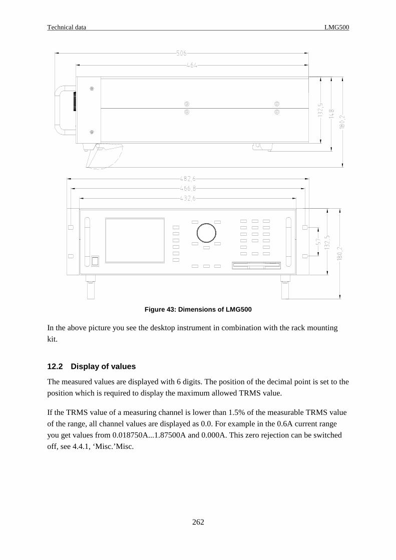
Technical data LMG500
262
Figure 43: Dimensions of LMG500
In the above picture you see the desktop instrument in combination with the rack mounting
kit.
12.2 Display of values
The measured values are displayed with 6 digits. The position of the decimal point is set to the
position which is required to display the maximum allowed TRMS value.
If the TRMS value of a measuring channel is lower than 1.5% of the measurable TRMS value
of the range, all channel values are displayed as 0.0. For example in the 0.6A current range
you get values from 0.018750A...1.87500A and 0.000A. This zero rejection can be switched
off, see 4.4.1, ‘Misc.’Misc.
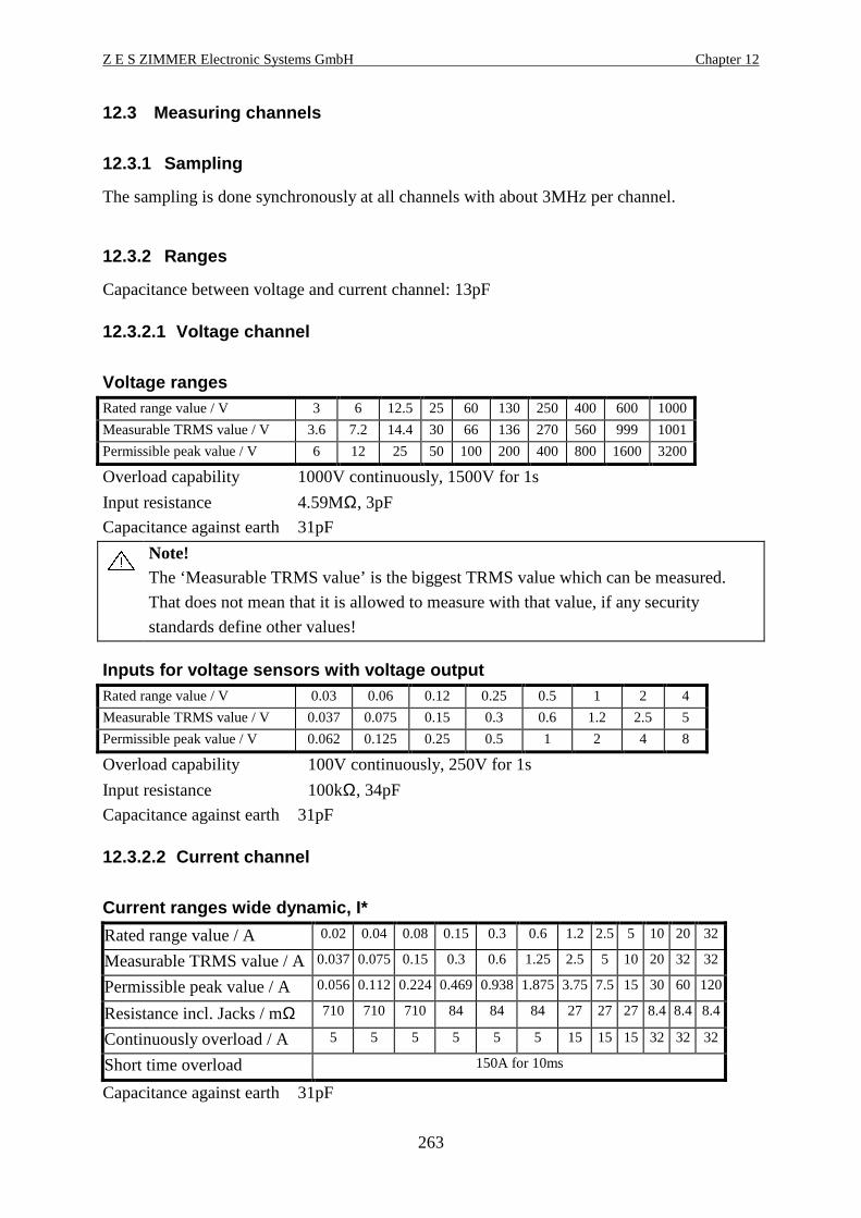
Z E S ZIMMER Electronic Systems GmbH Chapter 12
263
12.3 Measuring channels
12.3.1 Sampling
The sampling is done synchronously at all channels with about 3MHz per channel.
12.3.2 Ranges
Capacitance between voltage and current channel: 13pF
12.3.2.1 Voltage channel
Voltage rangesRated range value / V 3 6 12.5 25 60 130 250 400 600 1000
Measurable TRMS value / V 3.6 7.2 14.4 30 66 136 270 560 9991001
Permissible peak value / V 6 12 25 50 100 200 400 800 1600 3200
Overload capability 1000V continuously, 1500V for 1s
Input resistance 4.59MΩ, 3pF
Capacitance against earth 31pF
Note!The ‘Measurable TRMS value’ is the biggest TRMS value which can be measured.
That does not mean that it is allowed to measure with that value, if any security
standards define other values!
Inputs for voltage sensors with voltage outputRated range value / V 0.03 0.06 0.12 0.25 0.5 1 2 4
Measurable TRMS value / V 0.037 0.075 0.15 0.3 0.6 1.2 2.55
Permissible peak value / V 0.062 0.125 0.25 0.5 1 2 4 8
Overload capability 100V continuously, 250V for 1s
Input resistance 100kΩ, 34pF
Capacitance against earth 31pF
12.3.2.2 Current channel
Current ranges wide dynamic, I*
Rated range value / A 0.02 0.04 0.08 0.15 0.3 0.6 1.2 2.5 5 10 20 32
Measurable TRMS value / A0.037 0.075 0.15 0.3 0.6 1.25 2.5 5 10 20 32 32
Permissible peak value / A 0.056 0.112 0.224 0.469 0.938 1.875 3.75 7.5 15 30 60 120
Resistance incl. Jacks / mΩ 710 710 710 84 84 84 27 27 27 8.4 8.4 8.4
Continuously overload / A 5 5 5 5 5 5 15 15 15 32 32 32
Short time overload 150A for 10ms
Capacitance against earth 31pF
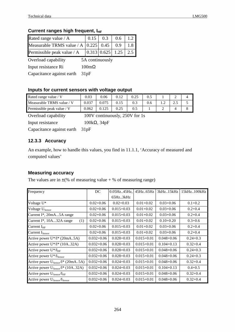
Technical data LMG500
264
Current ranges high frequent, I HF
Rated range value / A 0.15 0.3 0.6 1.2
Measurable TRMS value / A 0.225 0.45 0.9 1.8
Permissible peak value / A 0.313 0.625 1.25 2.5
Overload capability 5A continuously
Input resistance Ri 100mΩCapacitance against earth 31pF
Inputs for current sensors with voltage outputRated range value / V 0.03 0.06 0.12 0.25 0.5 1 2 4
Measurable TRMS value / V 0.037 0.075 0.15 0.3 0.6 1.2 2.55
Permissible peak value / V 0.062 0.125 0.25 0.5 1 2 4 8
Overload capability 100V continuously, 250V for 1s
Input resistance 100kΩ, 34pF
Capacitance against earth 31pF
12.3.3 Accuracy
An example, how to handle this values, you find in 11.1.1, ‘Accuracy of measured and
computed values’
Measuring accuracyThe values are in ±(% of measuring value + % of measuring range)
Frequency DC 0.05Hz..45Hz,
65Hz..3kHz
45Hz..65Hz 3kHz..15kHz 15kHz..100kHz
Voltage U* 0.02+0.06 0.02+0.03 0.01+0.02 0.03+0.06 0.1+0.2
Voltage USensor 0.02+0.06 0.015+0.03 0.01+0.02 0.03+0.06 0.2+0.4
Current I*, 20mA...5A range 0.02+0.06 0.015+0.03 0.01+0.02 0.03+0.06 0.2+0.4
Current I*, 10A...32A range (1) 0.02+0.06 0.015+0.03 0.01+0.02 0.10+0.20 0.3+0.6
Current IHF 0.02+0.06 0.015+0.03 0.01+0.02 0.03+0.06 0.2+0.4
Current ISensor 0.02+0.06 0.015+0.03 0.01+0.02 0.03+0.06 0.2+0.4
Active power U*/I* (20mA..5A) 0.032+0.06 0.028+0.03 0.015+0.01 0.048+0.06 0.24+0.3
Active power U*/I* (10A..32A) 0.032+0.06 0.028+0.03 0.015+0.01 0.104+0.13 0.32+0.4
Active power U*/IHF 0.032+0.06 0.028+0.03 0.015+0.01 0.048+0.06 0.24+0.3
Active power U*/ISensor 0.032+0.06 0.028+0.03 0.015+0.01 0.048+0.06 0.24+0.3
Active power USensor/I* (20mA..5A) 0.032+0.06 0.024+0.03 0.015+0.01 0.048+0.06 0.32+0.4
Active power USensor/I* (10A..32A) 0.032+0.06 0.024+0.03 0.015+0.01 0.104+0.13 0.4+0.5
Active power USensor/IHF 0.032+0.06 0.024+0.03 0.015+0.01 0.048+0.06 0.32+0.4
Active power USensor/ISensor 0.032+0.06 0.024+0.03 0.015+0.01 0.048+0.06 0.32+0.4

Z E S ZIMMER Electronic Systems GmbH Chapter 12
265
Frequency/Hz 100kHz..500kHz 500kHz..
1MHz
1MHz..3MHz 3MHz..10MHz
Voltage U* 0.5+1.0 0.5+1.0 3+3 f/1MHz*1.2 + f/1MHz*1.2
Voltage USensor 0.4+0.8 0.4+0.8 f/1MHz*0.7 + f/1MHz*1.5 f/1MHz*0.7 + f/1MHz*1.5
Current I*, 20mA...5A range 0.5+1.0 0.5+1.0 f/1MHz*1 + f/1MHz*2 -
Current I*, 10A...32A range (1) f/100kHz*0.8 + f/100kHz*1.2 - - -
Current IHF 0.5+1.0 0.5+1.0 f/1MHz*1 + f/1MHz*2 -
Current ISensor 0.4+0.8 0.4+0.8 f/1MHz*0.7 + f/1MHz*1.5 f/1MHz*0.7 + f/1MHz*1.5
Active power U*/I* (20mA..5A) 0.8+1.0 0.8+1.0 f/1MHz*3.2 + f/1MHz*2.5 -
Active power U*/I* (10A..32A) f/100kHz*1 + f/100kHz*1.1 - - -
Active power U*/IHF 0.8+1.0 0.8+1.0 f/1MHz*3.2 + f/1MHz*2.5 -
Active power U*/ISensor 0.72+0.9 0.72+0.9 f/1MHz*3 + f/1MHz*2.3 f/1MHz*1.5 + f/1MHz*1.4
Active power USensor/I* (20mA..5A) 0.72+0.9 0.72+0.9 f/1MHz*1.4 + f/1MHz*1.8 -
Active power USensor/I* (10A..32A) f/100kHz*1 + f/100kHz*1 - - -
Active power USensor/IHF 0.72+0.9 0.72+0.9 f/1MHz*1.4 + f/1MHz*2 -
Active power USensor/ISensor 0.64+0.8 0.64+0.8f/1MHz*1.12 + f/1MHz*1.5 f/1MHz*1.12 + f/1MHz*1.5
(1) additional error 22 30
A
AI
µ±
Accuracies based on:
1. sinusoidal voltages and currents
2. ambient temperature (23±3)°C, no additional heating or cooling (i.e. by sunlight or current
of air)
3. warm up time 1h
4. power range is the product of current and voltage range, 0≤|λ|≤1
5. Voltage and current are ≥ 10% and ≤110% of rated range
6. calibration interval 1 year
7. Adjustment was done at 23°C.
Temperature effect: 0.01% of measuring value / K
Uncertainty at standby powerIn the EC directive 2005/32/EC as well as in IEC/EN 62301 you can find requirements
concerning the power measuring uncertainty. A well adjusted and calibrated LMG500
combined with a well adjusted and calibrated shunt will fullfill the instrument uncertainty of
2% for power ≥0.5W or 0.01W for power <0.5W. The level of confidence is at least 95%. A
well fitting shunt type, usual measuring conditions and signals are assumed.
12.3.4 Common mode rejection
The common mode rejection was measured with a sinusoidal voltage of 100V against PE. For
the voltages ranges the signal was fed into the short circuit U and U* resp. U and Usensor. For
the current channel the signal was fed into I resp. I and Isensor (short circuit).

Technical data LMG500
266
Common mode
frequency
10kHz
Filter
U
3V range
Usensor
4V range
I*
32A range
IHF
0.15A range
Isensor
4A range
50Hz off >120dB >140dB >170dB >180dB >140dB
100kHz on >100dB >140dB >140dB >160dB >140dB
100kHz off >80dB >110dB >130dB >130dB >110dB
12.4 ZES sensors
Most ZES sensors have an EEPROM implemented in which we have stored the name, scaling,
ranges, adjustment and delay time of the sensor. The LMG500 recognises automatically,
which ZES sensor is connected and sets up the range menu. Further on we correct some of the
errors the sensor produces (transfer error, delay time, ...). So you get the best measuring
results with each sensor.
Due to the EEPROM this sensors offer a plug & play solution for your measuring. The usage
of the LMG sensor input offers several measuring ranges which increase the dynamic of the
connected sensors.
There is a very wide range of sensors available:
• Current clamps, transformers, hall sensors, flux compensated types, flexible Rogowski
sensors, shunts, ...
• Accuracies up to <0.01%
• Frequency range from DC to several hundred kHz
• Current range from <<1A up to several kA
For the exact specifications of all this sensors you find a detailed manual on the CD which is
delivered together with this manual. If this CD is missing or you have this manual only as
PDF file you can request it via email from ‘[email protected]’.
To adapt this sensors to a LMG500 you need a special adaptor, L50-Z14:
Figure 44: L50-Z14 adaptor
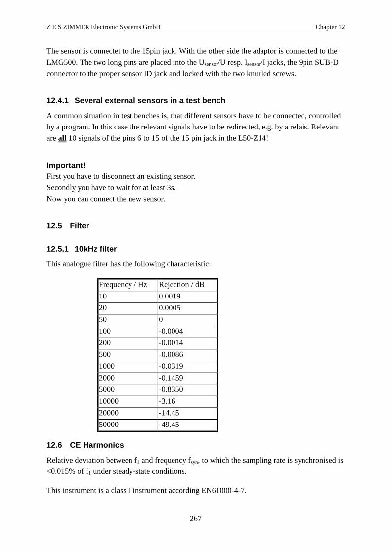
Z E S ZIMMER Electronic Systems GmbH Chapter 12
267
The sensor is connectet to the 15pin jack. With the other side the adaptor is connected to the
LMG500. The two long pins are placed into the Usensor/U resp. Isensor/I jacks, the 9pin SUB-D
connector to the proper sensor ID jack and locked with the two knurled screws.
12.4.1 Several external sensors in a test bench
A common situation in test benches is, that different sensors have to be connected, controlled
by a program. In this case the relevant signals have to be redirected, e.g. by a relais. Relevant
are all 10 signals of the pins 6 to 15 of the 15 pin jack in the L50-Z14!
Important!First you have to disconnect an existing sensor.
Secondly you have to wait for at least 3s.
Now you can connect the new sensor.
12.5 Filter
12.5.1 10kHz filter
This analogue filter has the following characteristic:
Frequency / Hz Rejection / dB
10 0.0019
20 0.0005
50 0
100 -0.0004
200 -0.0014
500 -0.0086
1000 -0.0319
2000 -0.1459
5000 -0.8350
10000 -3.16
20000 -14.45
50000 -49.45
12.6 CE Harmonics
Relative deviation between f1 and frequency fsyn, to which the sampling rate is synchronised is
<0.015% of f1 under steady-state conditions.
This instrument is a class I instrument according EN61000-4-7.
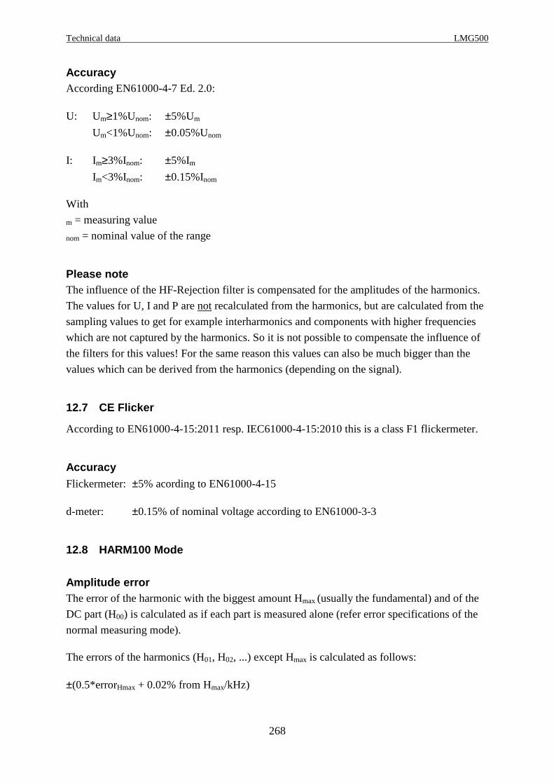
Technical data LMG500
268
AccuracyAccording EN61000-4-7 Ed. 2.0:
U: Um≥1%Unom: ±5%Um
Um<1%Unom: ±0.05%Unom
I: Im≥3%Inom: ±5%ImIm<3%Inom: ±0.15%Inom
With
m = measuring value
nom = nominal value of the range
Please noteThe influence of the HF-Rejection filter is compensated for the amplitudes of the harmonics.
The values for U, I and P are not recalculated from the harmonics, but are calculated from the
sampling values to get for example interharmonics and components with higher frequencies
which are not captured by the harmonics. So it is not possible to compensate the influence of
the filters for this values! For the same reason this values can also be much bigger than the
values which can be derived from the harmonics (depending on the signal).
12.7 CE Flicker
According to EN61000-4-15:2011 resp. IEC61000-4-15:2010 this is a class F1 flickermeter.
AccuracyFlickermeter: ±5% acording to EN61000-4-15
d-meter: ±0.15% of nominal voltage according to EN61000-3-3
12.8 HARM100 Mode
Amplitude errorThe error of the harmonic with the biggest amount Hmax (usually the fundamental) and of the
DC part (H00) is calculated as if each part is measured alone (refer error specifications of the
normal measuring mode).
The errors of the harmonics (H01, H02, ...) except Hmax is calculated as follows:
±(0.5*errorHmax + 0.02% from Hmax/kHz)

Z E S ZIMMER Electronic Systems GmbH Chapter 12
269
This errors are valid if the amplitude of the harmonics are higher than 0.1% of the full scale
peak value.
Phase error±(0.15° + 0.25° / kHz)
This errors are valid if the amplitude of the harmonics are higher than 0.1% of the full scale
peak value.
12.9 Processing signal interface (option L50-O3 )
The 8 functional groups are isolated against each other (for details please refer 13.6,
‘Functional block diagram processing signal interface’). The allowed working voltage is 25V
between the groups. The testing voltage is 500V.
The analogue inputs and outputs have nominal ±10V signal range, but in fact they are able to
handle ±20V resp. ±11V.
The processing signal interface has two connectors (Analogue/Digital I/O A and B) with the
following inputs and outputs. Each connector is compatible to LMG95 and LMG450.
• 8 analogue outputs with ±10V. The outputs are updated with each measuring cycle for
normal values. All analogue outputs have one common ground (AOut_GND) which is
isolated from all other grounds.
• 8 analogue inputs with ±20V. This values are displayed after each measuring cycle. All
analogue inputs have one common ground (AIn_GND) which is isolated from all other
grounds.
• 4 digital outputs A (open collector outputs). They are updated with each measuring cycle.
They have one common ground (DOut_GND_A) which is isolated from all other grounds.
• 4 digital outputs B (open collector outputs). They are updated with each measuring cycle.
They have one common ground (DOut_GND_B) which is isolated from all other grounds.
• 4 digital inputs A. They have one common ground (DIn_GND_A) which is isolated from
all other grounds.
• 4 digital inputs B. They have one common ground (DIn_GND_B) which is isolated from
all other grounds.
• 1 frequency input A with sensor supply. It can measure frequency and direction of a
rotation speed converter. This frequency input and it’s supply have a common ground
(Aux_F_GND_A) which is isolated from all other grounds. Via FIn_5 you can apply the
frequency, FIn_6 gives the direction information. If not used as a frequency input, the state
of FIn_5 and FIn_6 are displayed like a usual digital input.
• 1 frequency input B with sensor supply. It can measure frequency and direction of a
rotation speed converter. This frequency input and it’s supply have a common ground

Technical data LMG500
270
(Aux_F_GND_B) which is isolated from all other grounds. Via FIn_11 you can apply the
frequency, FIn_12 gives the direction information. If not used as a frequency input, the
state of FIn_11 and FIn_12 are displayed like a usual digital input.
The connectors have the following pinout:
1 AIn_1
AIn_2
AOut_1
AOut_2
AOut_GND
DIn_GND_A
DIn_1
DIn_2
DOut_1
DOut_GND_A
DOut_2
FIn_5
FIn_6
2
3
4
5
6
7
8
9
10
11
12
14AIn_4
AIn_3
AIn_GND
AOut_4
AOut_3
DIn_3
DIn_4
DOut_4
DOut_3
Aux-5V_A
Aux_F_GND_A
Aux+5V_A
15
16
17
18
19
20
21
22
23
24
2513
1 AIn_5
AIn_6
AOut_5
AOut_6
AOut_GND
DIn_GND_B
DIn_7
DIn_8
DOut_5
DOut_GND_B
DOut_6
FIn_11
FIn_12
2
3
4
5
6
7
8
9
10
11
12
14AIn_8
AIn_7
AIn_GND
AOut_8
AOut_7
DIn_9
DIn_10
DOut_8
DOut_7
Aux-5V_B
Aux_F_GND_B
Aux+5V_B
15
16
17
18
19
20
21
22
23
24
2513
Figure 45: Processing Signal Interface Connector A and B
For information how to setup this values see 4.4.2.2, ‘Processing signal interface’
12.9.1 Analogue inputs
Pins: AIn_1 to AIn_8 with AIn_GND
Resolution: 24Bit
Accuracy: ±(0.05% of measuring value + 0.05% of full scale)
Input signal: ±20V
Overload capability: -30...+30V
Input resistance: 100kΩ±0.1%
12.9.2 Analogue outputs
Pins AOut_1 to AOut_8 with AOut_GND
Resolution: 14Bit
Accuracy: ±(0.05% of output value + 0.05% of full scale value)
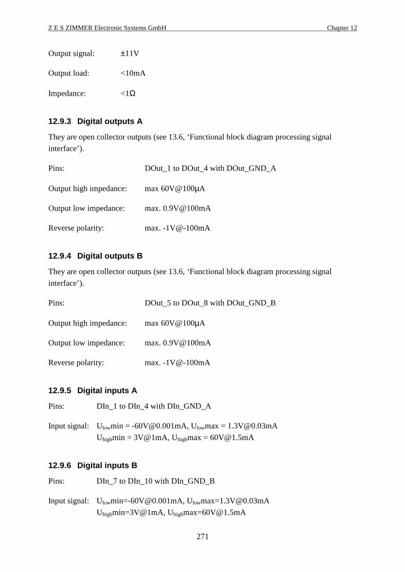
Z E S ZIMMER Electronic Systems GmbH Chapter 12
271
Output signal: ±11V
Output load: <10mA
Impedance: <1Ω
12.9.3 Digital outputs A
They are open collector outputs (see 13.6, ‘Functional block diagram processing signal
interface’).
Pins: DOut_1 to DOut_4 with DOut_GND_A
Output high impedance: max 60V@100µA
Output low impedance: max. 0.9V@100mA
Reverse polarity: max. -1V@-100mA
12.9.4 Digital outputs B
They are open collector outputs (see 13.6, ‘Functional block diagram processing signal
interface’).
Pins: DOut_5 to DOut_8 with DOut_GND_B
Output high impedance: max 60V@100µA
Output low impedance: max. 0.9V@100mA
Reverse polarity: max. -1V@-100mA
12.9.5 Digital inputs A
Pins: DIn_1 to DIn_4 with DIn_GND_A
Input signal: Ulowmin = [email protected], Ulowmax = [email protected]
Uhighmin = 3V@1mA, Uhighmax = [email protected]
12.9.6 Digital inputs B
Pins: DIn_7 to DIn_10 with DIn_GND_B
Input signal: [email protected], [email protected]
Uhighmin=3V@1mA, [email protected]
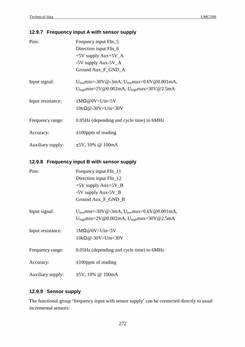
Technical data LMG500
272
12.9.7 Frequency input A with sensor supply
Pins: Frequncy input FIn_5
Direction input FIn_6
+5V supply Aux+5V_A
-5V supply Aux-5V_A
Ground Aux_F_GND_A
Input signal: Ulowmin=-30V@-3mA, [email protected],
[email protected], [email protected]
Input resistance: 1MΩ@0V<Uin<5V
10kΩ@-30V<Uin<30V
Frequency range: 0.05Hz (depending and cycle time) to 6MHz
Accuracy: ±100ppm of reading
Auxiliary supply: ±5V, 10% @ 100mA
12.9.8 Frequency input B with sensor supply
Pins: Frequncy input FIn_11
Direction input FIn_12
+5V supply Aux+5V_B
-5V supply Aux-5V_B
Ground Aux_F_GND_B
Input signal: Ulowmin=-30V@-3mA, [email protected],
[email protected], [email protected]
Input resistance: 1MΩ@0V<Uin<5V
10kΩ@-30V<Uin<30V
Frequency range: 0.05Hz (depending and cycle time) to 6MHz
Accuracy: ±100ppm of reading
Auxiliary supply: ±5V, 10% @ 100mA
12.9.9 Sensor supply
The functional group ‘frequency input with sensor supply’ can be connected directly to usual
incremental sensors:

Z E S ZIMMER Electronic Systems GmbH Chapter 12
273
HTL version(Supply 8...30V, max. 100mA, differential output):
Aux+5V to: +Ub
Aux-5V to: 0V
Shield of Sub-D to: Shield of cable
TTL version(Supply 5V, max. 100mA, TTL output):
Aux+5V to: +Ub
Aux_F_GND to: 0V
Shield of Sub-D to: Shield of cable
12.9.10 Frequency/direction input
Incremental sensors without direction informationConnect them to FIn_5 resp. FIn_11 only. Let FIn_6 resp. FIn_12 open!
Incremental sensors with direction informationConnect the frequency track (usually track A) to FIn_5 resp. FIn_11.
Connect the direction track (usually track B) to FIn_6 resp. FIn_12.
A positive frequency is displayed, if the direction signal is high at the rising edge of the
frequency signal.
A negative frequency is displayed, if the direction signal is low at the rising edge of the
frequency signal.
If this is opposite to what you want, change the tracks or use a negative frequency scaling.
12.10 Timebase
The timebase which controls the energy measuring and the internal clock has an accuracy of
±100ppm
12.11 Frequency measuring
0.05Hz...3MHz, ±100ppm

Technical data LMG500
274
12.12 Scope memory
Size: 1048576 words for u,
1048576 words for i,
1048576 words for p,
together for all channels of one instrument resp. one master or one slave.
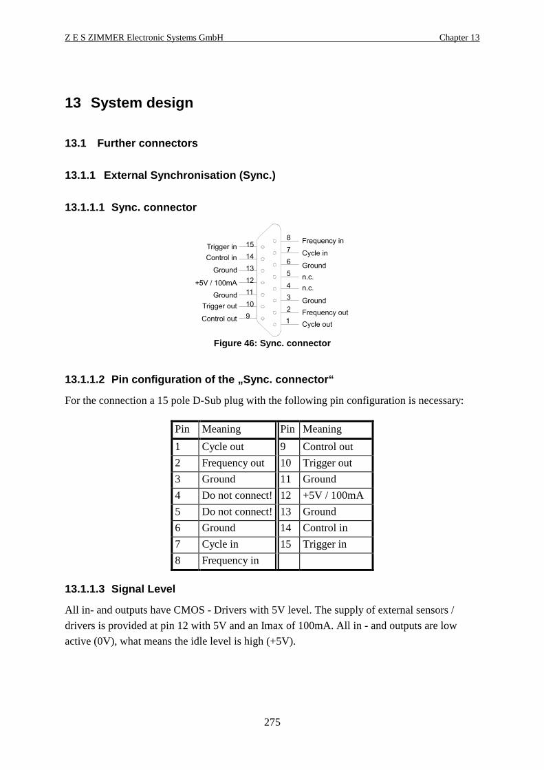
Z E S ZIMMER Electronic Systems GmbH Chapter 13
275
13 System design
13.1 Further connectors
13.1.1 External Synchronisation (Sync.)
13.1.1.1 Sync. connector
Figure 46: Sync. connector
13.1.1.2 Pin configuration of the „Sync. connector“
For the connection a 15 pole D-Sub plug with the following pin configuration is necessary:
Pin Meaning Pin Meaning
1 Cycle out 9 Control out
2 Frequency out 10 Trigger out
3 Ground 11 Ground
4 Do not connect! 12 +5V / 100mA
5 Do not connect! 13 Ground
6 Ground 14 Control in
7 Cycle in 15 Trigger in
8 Frequency in
13.1.1.3 Signal Level
All in- and outputs have CMOS - Drivers with 5V level. The supply of external sensors /
drivers is provided at pin 12 with 5V and an Imax of 100mA. All in - and outputs are low
active (0V), what means the idle level is high (+5V).

System design LMG500
276
13.1.1.4 Function of the signals
Frequency inMaximum 100kHz frequency synchronous to the frequency of the measured signal. If the
LMG is set to Ext. Sync. this frequency is used for synchronisation. The rising edge of this
signal replaces the positive zero crossing of the usual sync detector.
Frequency outMeasured frequency of group A, depending on the synchronisation source of the group.
Control inControl of the energy measurement. With the next high low transition the integration is reset
(if summing mode is inactive) and started. The integration stops only at transitions from low
to high. The functionality of the transitions:
high → low start key
low → high stop key
Control outStatus of the energy measurement high level if the integration is stopped, low level if the
integration is running.
Cycle inControl of the measurement cycle. The period must be longer than 50ms and shorter than 60
seconds and longer than the period of the measured signal. The pulse duty factor can be 50%.
Example: To measure a 5Hz signal the measurement cycle must be bigger than 200ms.
Attention: Use only with valid control periods otherwise there can be a system fault of the
meters. This input is normally not used.
The rising edge of this signal finishes one cycle and starts a new one.
Cycle outPulse for about 10µs per measurement cycle.
Trigger in/outnot used.

Z E S ZIMMER Electronic Systems GmbH Chapter 13
277
13.1.1.5 Synchronised measurements of two LMG500
Following a possibility is described, how two LMG500 can perform synchronized
measurements. Please don’t mix up this posibility with the combining of two LMG500 to a
real 8 channel instrument. For a real 8 channel instrument you need a connection cable
L50-Z13 and have to bring one instrument into the slave mode (see chapter 4.4.1, ‘Misc.’ and
chapter 3.4, ‘Coupling of two LMG500 (L50-Z13) for a 8 channel instrument’).
13.1.1.5.1 General
Two LMG500 (or also LMG450) may measure synchronous if they are connected with the
option L45-Z13 „Master-Slave cable“. Because of this the measurement of even 8 phases in
four groups is possible. In the following documentation the groups are named: group A1 and
B1 are the groups of the first LMG500. Group A2 and B2 are the groups of the second meter.
13.1.1.5.2 Connection of the meters
The Master-Slave cable must be fitted to the „Sync“-sockets of both meters. The cable is
symmetric, so there is no wiring direction.
13.1.1.5.3 Pin configuration of the Master-Slave ca ble L45-Z13:
Plug 1 Plug 2 Signal ST1 ST2
1 7 Cycle Out In
2 8 Frequency Out In
9 14 Control Out In
10 15 Trigger Out In
7 1 Cycle In Out
8 2 Frequency In Out
14 9 Control In Out
15 10 Trigger In Out
Ground and Screen are connected to pin 3 of both plugs.
Synchronisation stages, Set-up of the MetersThe synchronisation of the measurement can be done in different stages. Each stage is
independent to all others.
A) Synchronisation of the measurement signalThis stage has no master-slave functionality. The inputs „Frequency in“ are connected with
the synchronisation frequency of group A of the other power meter. The adjustments of this
parameter can be set separately for each group in every meter in the Measure menu with Sync.
System design LMG500
278
Because of this all groups can synchronise the measuring of one common signal.
Example for the settings:
Group A1 of the first meter is set to U1.
Group A2 of the second meter is set to Ext., by this the synchronisation is set to U1 of the first
meter.
Group B1 is set to Ext., by this it gets the synchronisation frequency via A2 what means U1.
Group B2 is set to Ext., by this it gets the synchronisation frequency of A1 what means U1.
If the groups A of both meters are set to Ext. there is no common synchronisation frequency
and the measuring is asynchronous.
B) Synchronisation of the measuring cycleThis stage has a master-slave functionality!
For a simultaneous generation of the measuring values of two LMG the measuring cycle of
the meters has to be exactly the same. Therefore the cycle time of the slave meter can be set to
0ms in the Measure (refer 5.1.1 Globals tab) menu.
In the status bar „0 Ext“ is shown and the green bar flashes every second.
The measuring values of both meters are now generated at exactly the same moment and a
comparison of the values is possible.
Because of the master-slave meaning this adjustment can only be set in one meter. If both
meters are set to 0ms the measurement stops!
C) Synchronisation of the energy measurementThis stage has no master-slave functionality but a control of a master LMG is recommended
(if existing from the last top).
The energy measurement of both meters has to be set to the same mode and should be reset
(refer 5.4.5.1 Integration menu).
The measurement can be started and stopped mutual with the keys „Start“ and „Stop“. A
remote controlled measurement is also possible (see the following section)
D) External synchronisation signalIf the measurement should be synchronised to an additional external signal, this signal has to
be connected to the pins of the D-Sub plug. The plug fitted to the meter which should be
synchronised external has to be opened and the „Freq“ and „Control“ inputs must be
disconnected. After this the external signal can be connected to this inputs.
If the signals are connected to the master LMG also the slave LMG can use them, because the
master outputs are still connected to slave inputs:
Pin 8 Input for the external synchronisation frequency
Pin 7 Input for the cycle
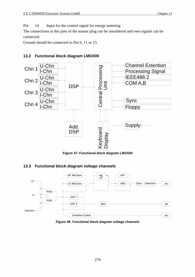
Z E S ZIMMER Electronic Systems GmbH Chapter 13
279
Pin 14 Input for the control signal for energy metering
The connections at this pins of the master plug can be unsoldered and own signals can be
connected.
Ground should be connected to Pin 6, 11 or 13.
13.2 Functional block diagram LMG500
U-Chn
Cen
tral
Pro
cess
ing
Uni
t
DSP
Channel Extention
Key
boar
d
Processing Signal
Dis
play
IEEE488.2COM A,B
SyncFloppy
U-Chn
U-Chn
U-Chn
Chn 1
Chn 2
Chn 3
Chn 4
I-Chn
I-Chn
Add.DSP
Supply
I-Chn
I-Chn
Figure 47: Functional block diagram LMG500
13.3 Functional block diagram voltage channels
Figure 48: Functional block diagram voltage channel s
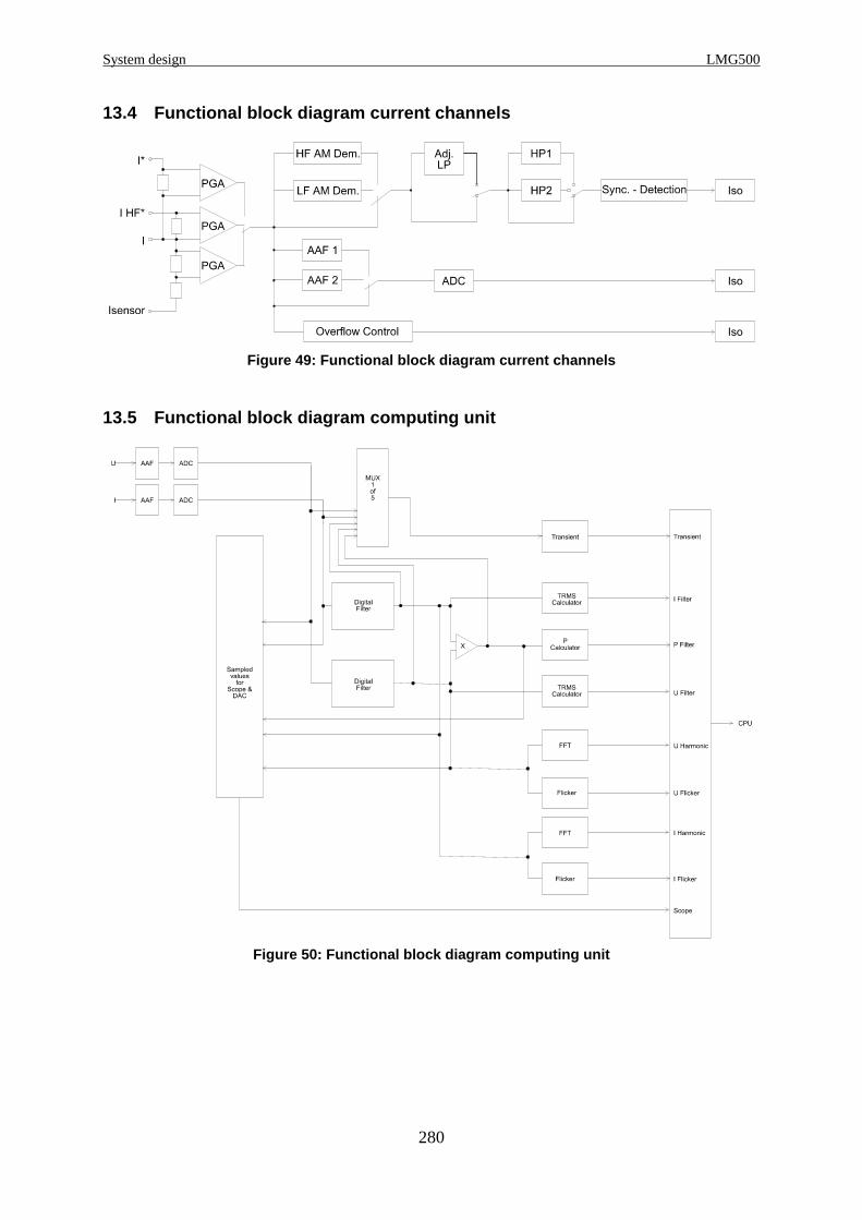
System design LMG500
280
13.4 Functional block diagram current channels
Figure 49: Functional block diagram current channel s
13.5 Functional block diagram computing unit
Figure 50: Functional block diagram computing unit

Z E S ZIMMER Electronic Systems GmbH Chapter 13
281
13.6 Functional block diagram processing signal int erface
ISO
ISO
ISO
ISO
ISO
ISO
ISO
ISO
ISO
ISO
ISO
ISO
DAC
DAC
DAC
DAC
DAC
DAC
DAC
DAC
Freq. In B
Freq. In A
Dir. In B
Dir. In A
ISO MUX1 of 8
Control - Logic
Dig In
Dig In
Dig In
Dig In
Dig In
Dig In
Dig In
Dig In
ISO
ISO
ISO
ISO
Main Processor
(B1, AIn_5)
(A1, AIn_1)
(B2, AIn_6)
(A2, AIn_2)
(B15, AIn_7)
(A15, AIn_3)
(B14, AIn_8)
(A14, AIn_4)
(A16/B16, AIn_GND)
(B3, AOut_5)
(A3, AOut_1)
(B4, AOut_6)
(A4, AOut_2)
(B18, AOut_7)
(A18, AOut_3)
(B17, AOut_8)
(A17, AOut_4)
(A5/B5, AOut_GND)
(B12, DIn_11)
(A12, DIn_5)
(B13, DIn_22)
(A13, DIn_6)
(B23, Aux -5V_B)
(A23, Aux -5V_A)
(B25, Aux +5V_B)
(A25, Aux +5V_A)
(B24, Aux_F_GND_B)
(A24, Aux_F_GND_A)
(A9, Dout_1)
(B9, Dout_5)
(A11, Dout_2)
(B11, Dout_6)
(A22, Dout_3)
(B22, Dout_7)
(A21, Dout_4)
(B21, Dout_8)
(A10, DOut_GND_A)
(B10, DOut_GND_B)
(A7, DIn_1)
(B7, DIn_7)
(A8, DIn_2)
(B8, DIn_8)
(A20, DIn_3)
(B20, DIn_9)
(A19, DIn_4)
(B19, DIn_10)
(A6, DIn_GND_A)
(B6, DIn_GND_B)
ADC
Figure 51: Functional block diagram processing sign al interface


Z E S ZIMMER Electronic Systems GmbH Chapter 14
283
14 Glossary
Catchword Meaning
100 Harmonics Mode in which 99 harmonics of U, I and P are calculated.
AAAF ⇒ Anti Aliasing Filter.
AC Alternating current; instantaneous values of voltage and
current are time depending signals which have positive and
negative values.
AC coupling Used to remove the DC parts of a signal by using a high
pass filter.
AC+DC coupling Couples the complete signal without rejecting any parts.
Accuracy Declaration of the errors which will be made in measuring.
Active energy Energy which is consumpted by the (usually ohmic) load.
Active power Power which is consumpted in the (usually ohmic) load.
Actual flicker level Pmom ⇒ Instantaneous flicker level.
Aliasing Distortion caused by signal parts, which are created through
the violation of the sampling (Nyquist, Shannon) theorem
(bandwidth ≥ ½ sampling frequency). This can be prevented
by using ⇒ Anti Aliasing Filter.
Allowed limits Limits which are declared in standards.
AM Amplitude modulation; one signal is multiplied with
another one; A typical example is a rapid fire control, where
a 50Hz sine wave is modulated with a slower rectangular
signal.
Amplitude error Error in the modulus of a measuring result.
Amplitude modulation ⇒ AM.
Analogue I/O Analogue input and output, the LMG series supplies four
separated inputs and outputs for analogue signals: 0-10V.
Analogue Input ⇒ Analogue I/O.
Analogue Output ⇒ Analogue I/O.
AND Condition Register Register in which a flag is set, if two conditions are true.
Anti-Aliasing-Filter Filter which cuts off signal parts which might produce
aliasing.
Apparent energy Energy which seems to be consumpted by the load; ⇒
Apparent power. It is the integration of the apparent power.
Apparent power Power which seems to be consumpted; it is calculated by
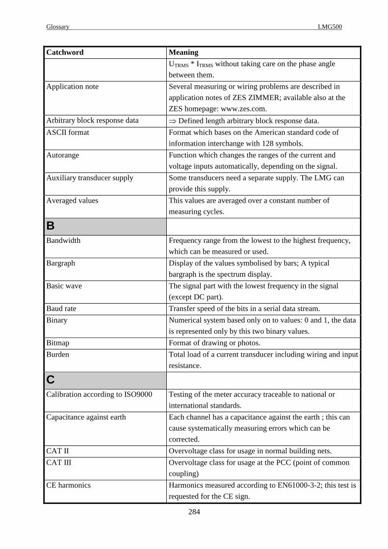
Glossary LMG500
284
Catchword Meaning
UTRMS * ITRMS without taking care on the phase angle
between them.
Application note Several measuring or wiring problems are described in
application notes of ZES ZIMMER; available also at the
ZES homepage: www.zes.com.
Arbitrary block response data ⇒ Defined length arbitrary block response data.
ASCII format Format which bases on the American standard code of
information interchange with 128 symbols.
Autorange Function which changes the ranges of the current and
voltage inputs automatically, depending on the signal.
Auxiliary transducer supply Some transducers need a separate supply. The LMG can
provide this supply.
Averaged values This values are averaged over a constant number of
measuring cycles.
BBandwidth Frequency range from the lowest to the highest frequency,
which can be measured or used.
Bargraph Display of the values symbolised by bars; A typical
bargraph is the spectrum display.
Basic wave The signal part with the lowest frequency in the signal
(except DC part).
Baud rate Transfer speed of the bits in a serial data stream.
Binary Numerical system based only on to values: 0 and 1, the data
is represented only by this two binary values.
Bitmap Format of drawing or photos.
Burden Total load of a current transducer including wiring and input
resistance.
CCalibration according to ISO9000 Testing of the meter accuracy traceable to national or
international standards.
Capacitance against earth Each channel has a capacitance against the earth ; this can
cause systematically measuring errors which can be
corrected.
CAT II Overvoltage class for usage in normal building nets.
CAT III Overvoltage class for usage at the PCC (point of common
coupling)
CE harmonics Harmonics measured according to EN61000-3-2; this test is
requested for the CE sign.

Z E S ZIMMER Electronic Systems GmbH Chapter 14
285
Catchword Meaning
CE-Flicker Flicker measured according to EN61000-3-3; this test is
requested for the CE sign.
Channel Hardware which acts as an interface between the test circuit
and the instrument, these are U, I and P channels (P=U*I).
Charge The integration of the current over the time; this charge can
be stored for example in an accumulator the unit is Ah.
Class A, B, C, D Different kinds of equipment under test for EN61000-3-2
tests are assigned to this test classes.
COM interfaces Serial Interface, mostly 9 pole SUB-D socket or 25 pole
SUB-D socket.
Comma separated Data format in which each value is separated by a ‘,’.
Command set A couple of commands to remote control the instrument
Common mode rejection Relation of the displayed value to a common floating signal
on all inputs of a measuring channel; a high common mode
rejection is necessary for high accuracy.
Condition instruction Instruction which will only be executed if a condition has
been fulfilled.
Constant Value which will not change over time.
Continuous measuring Measuring without any gaps.
Core parameter measuring circuit The core parameters, like hysteresis and magnetic flux, can
be determined through power measuring.
Correct current
Correct voltage measuring
You can only measure one of these parameters in the correct
way, because the impedance of the voltage / current channel
has an influence on the measuring channel. This is a
systematically measuring error, which can be corrected.
Coupling This defines which parts of a signal are fed into the next
stage. ⇒ AC coupling.
Crest factor Ratio of peak value to TRMS value; very important when
using analogue instruments.
Current clamp Tool to measure currents; work like a removable
transformer.
Current transducer Similar to current clamps, but placed unremovable in the
measurement circuit.
Cursor Representation of the place on which the next text input will
follow; in graphics the cursor marks a special point of the
waveform.
Custom menu Menu defined by the customer himself.
Cycle time Time which defines a measuring cycle must be higher than
the period time of the basic wave.

Glossary LMG500
286
Catchword Meaning
DD. U. T. ‘Device under test’: equipment which should be measured.
Data output format Format which is used to transfer data from the meter to a PC
or data logger.
DC value ‘Direct current’; signal without alternating components.
This signal is constant over the time.
Default parameters Parameters defined by the manufacturer; the instrument is
set to this parameters when it leaves the factory.
Defined length arbitrary block
response data
Data transfer in blocks with a defined length and random
contents inside the blocks; there can be for example the ⇒
EOS character which will be interpreted as data instead of
EOS. The fastest way to get data.
Demodulation Inverse function to ⇒ modulation; remove the carrier and
you get the signal you want.
Desired integration time Time in which the power is integrated, set by the user.
Device Every meter or equipment take place in the measurement
(Printer, PC ...).
Device under test ⇒ D. U. T.
DFT algorithm Discrete Fourier transformation; operation with discrete
values using the Fourier integral to get the harmonics of a
signal.
Digital filter Filter built up with digital components and software.
Digital Input Like ⇒ Analogue inputs the LMG series provides digital
inputs, to read external states.
Digital Output Like ⇒ Analogue outputs the LMG series provides digital
outputs, which can be used to signalise states (e.g. alarm
outputs).
DIP switches Small hardware switches to set up a meter parameter, like
communication speed.
Direction input Input for motor testing to measure the rotary direction of the
motor.
Dot joiner Connects the dots of the measured graph; it improves the
look of a graph.
EE. U. T. ⇒ D. U. T.
Echo Repetition of characters sent via the RS232 to the
instrument.
Edit line Line in which you can change a value or text.

Z E S ZIMMER Electronic Systems GmbH Chapter 14
287
Catchword Meaning
Efficiency measurement Efficiency is the relation between the output power and the
input power of an E. U. T.
EN61000-3-2, EN61000-4-7
EN61000-3-3, EN61000-4-15
Standards which describe the harmonic measuring
Standards which describe the flicker measuring.
End of string character ‘<lf>‘, ‘<cr>, <cr><lf>‘ are examples for EOS characters.
Energy Integration of the power which is consumpted by a
consumer or a device in a defined time.
envelope It is the curve which covers a mixed frequency signal
connecting the peak values of the fast frequency; a curve
defined by EN61000-3-2 to define if a device belongs to
Class D or not.
EOS ⇒ End of string.
Equipment under test ⇒ D. U. T.
ESC key Key used to cancel an entering mode and to quit an error
message.
Extended Trigger Mode in which the trigger conditions can be set up very
differentiated to measure even modulated signal.
External current transformer Device to transform high currents to lower ones.
External shunt Changes currents into voltage with defined ratio.
External synchronisation jack Input for an external synchronisation source.
FFalling edge Opposite of rising edge; the logic signal turns from the high
potential to the lower one.
FIFO First in first out; method how the in- and output of memory
is handled.
Filter Device which cuts off frequencies which are not useful; e.g.
high pass filter cuts off low frequencies.
Flicker meter Device to measure flicker levels.
Fluctuating harmonics Harmonics not constant over time.
Form factor Ratio of TRMS value to rectified value; older meters could
only measure the rectified value and multiply it with the
form factor to get the TRMS value. The problem is, that the
form factor depends on the wave form. So with other wave
form you get an error. Modern instruments like the LMGs
measure independent to the form factor, so you measure
always correct.
Formula editor Here you can set up formulas which will calculate different
parameters from the measured values.
Freeze The display values are not updated any more.
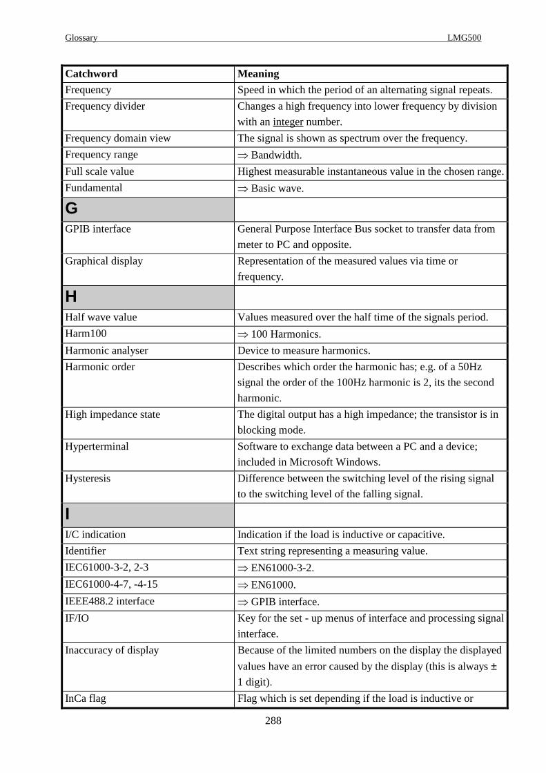
Glossary LMG500
288
Catchword Meaning
Frequency Speed in which the period of an alternating signal repeats.
Frequency divider Changes a high frequency into lower frequency by division
with an integer number.
Frequency domain view The signal is shown as spectrum over the frequency.
Frequency range ⇒ Bandwidth.
Full scale value Highest measurable instantaneous value in the chosen range.
Fundamental ⇒ Basic wave.
GGPIB interface General Purpose Interface Bus socket to transfer data from
meter to PC and opposite.
Graphical display Representation of the measured values via time or
frequency.
HHalf wave value Values measured over the half time of the signals period.
Harm100 ⇒ 100 Harmonics.
Harmonic analyser Device to measure harmonics.
Harmonic order Describes which order the harmonic has; e.g. of a 50Hz
signal the order of the 100Hz harmonic is 2, its the second
harmonic.
High impedance state The digital output has a high impedance; the transistor is in
blocking mode.
Hyperterminal Software to exchange data between a PC and a device;
included in Microsoft Windows.
Hysteresis Difference between the switching level of the rising signal
to the switching level of the falling signal.
II/C indication Indication if the load is inductive or capacitive.
Identifier Text string representing a measuring value.
IEC61000-3-2, 2-3 ⇒ EN61000-3-2.
IEC61000-4-7, -4-15 ⇒ EN61000.
IEEE488.2 interface ⇒ GPIB interface.
IF/IO Key for the set - up menus of interface and processing signal
interface.
Inaccuracy of display Because of the limited numbers on the display the displayed
values have an error caused by the display (this is always ±1 digit).
InCa flag Flag which is set depending if the load is inductive or
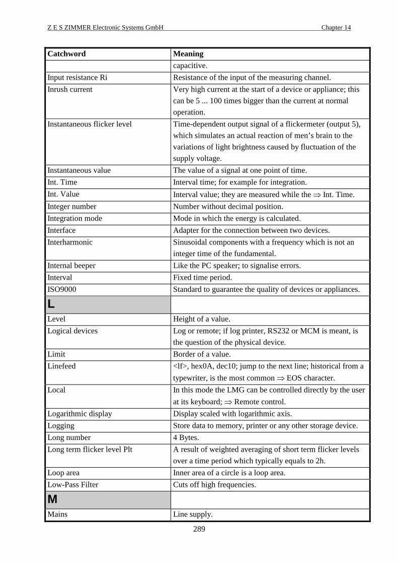
Z E S ZIMMER Electronic Systems GmbH Chapter 14
289
Catchword Meaning
capacitive.
Input resistance Ri Resistance of the input of the measuring channel.
Inrush current Very high current at the start of a device or appliance; this
can be 5 ... 100 times bigger than the current at normal
operation.
Instantaneous flicker level Time-dependent output signal of a flickermeter (output 5),
which simulates an actual reaction of men’s brain to the
variations of light brightness caused by fluctuation of the
supply voltage.
Instantaneous value The value of a signal at one point of time.
Int. Time Interval time; for example for integration.
Int. Value Interval value; they are measured while the ⇒ Int. Time.
Integer number Number without decimal position.
Integration mode Mode in which the energy is calculated.
Interface Adapter for the connection between two devices.
Interharmonic Sinusoidal components with a frequency which is not an
integer time of the fundamental.
Internal beeper Like the PC speaker; to signalise errors.
Interval Fixed time period.
ISO9000 Standard to guarantee the quality of devices or appliances.
LLevel Height of a value.
Logical devices Log or remote; if log printer, RS232 or MCM is meant, is
the question of the physical device.
Limit Border of a value.
Linefeed <lf>, hex0A, dec10; jump to the next line; historical from a
typewriter, is the most common ⇒ EOS character.
Local In this mode the LMG can be controlled directly by the user
at its keyboard; ⇒ Remote control.
Logarithmic display Display scaled with logarithmic axis.
Logging Store data to memory, printer or any other storage device.
Long number 4 Bytes.
Long term flicker level Plt A result of weighted averaging of short term flicker levels
over a time period which typically equals to 2h.
Loop area Inner area of a circle is a loop area.
Low-Pass Filter Cuts off high frequencies.
MMains Line supply.

Glossary LMG500
290
Catchword Meaning
Mains switch Switch to start up the instrument.
Manual range The range settings have to be done by the user.
Measuring converter Adapter to connect a meter to the ⇒ D. U. T.
Measuring cycle Cycle set up from the user. After this time the meter
calculates new values. The exact time depends on the
synchronisation frequency.
Measuring settings All parameters of the meter which influence the
measurement.
Memory card Random access memory card to store data.
Menu The whole measurement settings are divided in menus to get
a better survey.
Miscellaneous In this menu you can set up several parameters which have
no direct influence on the power measurement, like contrast
time and date.
Multimeter Meter which can measure several values like voltage,
current and resistance.
NNibble Half of a byte; upper or lower 4bit.
Noise Usually random signals with a high bandwidth which are
superposed to the useful signal.
Nondecimal numeric program data Data which can be represented as string instead of a
number; e. g. ‘Cont on’ instead of ‘Cont 1’.
Non-linear component losses Losses caused by non linear loads like inductivities or
capacitors or amplifier circuits.
Null modem Type of serial connection between a PC and another device;
the connection cable has two crossed conductor pairs.
OOpen collector outputs Passive outputs where the user has access to the collector of
the output transistor. You have to connect an external
voltage supply to this collector to use the output.
Operator Instruction which is taken into the calculation: +, -, *, /.
Option Key A string which can be used to implement software options
when the LMG is at the customer.
OR Condition Register Register which becomes true if an or condition is fulfilled.
Order ⇒ Harmonic order.
Overload capability A value how far a channel can be overloaded for a special
time.
Overload condition The instrument is in overload condition while the applied

Z E S ZIMMER Electronic Systems GmbH Chapter 14
291
Catchword Meaning
signal is too big for the selected range.
PPacked Data are transferred binary instead of ASCII format
Parallel interface ⇒ Serial interface; here the data is transferred in parallel.
Parity Even or odd number of 1’s in a binary data block; The LMG
works without parity.
Parsing The LMG tries to interpret a formula or interface string and
to react correctly.
Partial odd harmonic current The harmonic content of order 21, 23 ...
PCMCIA memory cards ⇒ Memory card; PCMCIA is the old name for the PC -
Card standard.
Peak current ranges Ranges with quiet small allowed TRMS values (because of
the heating up of the shunt) but very big allowed peak
values; very useful to measure ⇒ Inrush currents.
Peak value Value measured from the zero line to the highest peak of the
signal.
Peak-peak value Measured from the lowest to the highest peak of a signal.
Periodic integration mode In this mode the integration interval is repeated periodically.
Phase Conductor of the high potential; typically marked with L.
Phase angles Usually the angle between current and voltage.
Phase error The error in power caused by an additional phase shift in the
measuring equipment, for example the additional phase shift
of a current clamp.
Physical device Hardware, device (RS232, printer, GPIB...).
Plot function Mode in which cycle values (e.g. voltage, frequency, ...) are
displayed over time.
Power The energy of a time interval divided by the internal time
(e.g. cycle time); so the power is always an averaged value!!
Power factor Relation between active and apparent power.
Power measuring channel ⇒ Channel.
Power supply Source which provides the necessary voltage.
Pretrigger Time before the trigger condition, while which sample
values are stored.
Printer header Upper line of the printer like a title or headline.
Printer output Socket to connect a printer.
Processing signal interface Board with Analogue or Digital outputs.
Protocol Arrangements for communication between devices.
Pulse controlled currents A modulated current controls the device’s power; like in a
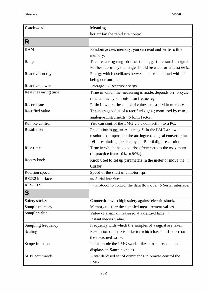
Glossary LMG500
292
Catchword Meaning
hot air fan the rapid fire control.
RRAM Random access memory; you can read and write to this
memory.
Range The measuring range defines the biggest measurable signal.
For best accuracy the range should be used for at least 66%.
Reactive energy Energy which oscillates between source and load without
being consumpted.
Reactive power Average ⇒ Reactive energy.
Real measuring time Time in which the measuring is made, depends on ⇒ cycle
time and ⇒ synchronisation frequency.
Record rate Ratio in which the sampled values are stored in memory.
Rectified value The average value of a rectified signal; measured by many
analogue instruments ⇒ form factor.
Remote control You can control the LMG via a connection to a PC.
Resolution Resolution is not ⇒ Accuracy!!! In the LMG are two
resolutions important: the analogue to digital converter has
16bit resolution, the display has 5 or 6 digit resolution.
Rise time Time in which the signal rises from zero to the maximum
(in practice from 10% to 90%).
Rotary knob Knob used to set up parameters in the meter or move the ⇒
Cursor.
Rotation speed Speed of the shaft of a motor; rpm.
RS232 interface ⇒ Serial interface.
RTS/CTS ⇒ Protocol to control the data flow of a ⇒ Serial interface.
SSafety socket Connection with high safety against electric shock.
Sample memory Memory to store the sampled measurement values.
Sample value Value of a signal measured at a defined time ⇒
Instantaneous Value.
Sampling frequency Frequency with which the samples of a signal are taken.
Scaling Resolution of an axis or factor which has an influence on
the measured value.
Scope function In this mode the LMG works like an oscilloscope and
displays ⇒ Sample values.
SCPI commands A standardised set of commands to remote control the
LMG.

Z E S ZIMMER Electronic Systems GmbH Chapter 14
293
Catchword Meaning
Sensors A small external device which converts a current or voltage
to a signal the LMG can measure.
Serial poll A PC program can ask every connected instrument in series
if it has data to send. Used by ⇒ GPIB.
SHORT headers Shorter set of commands, equivalent to ⇒ SCPI.
Short term flicker level A result of statistical processing of instantaneous flicker
level quantities over a time period, which typically equals to
10 min.
Shunt input Special socket to connect the small voltages of an external
shunt to the correct channel.
Shuttle knob ⇒ Rotary knob.
Signal coupling ⇒ AC coupling; This coupling affects the measured values.
Signal source Where you get a signal from; e.g. frequency generator.
Slewrate Relation between the voltage rise and the used time.
Softkey This keys change the meaning depending on the menu.
Software options Options which can be installed with software.
Software update Updates your software of the LMG. Available on the
homepage: www.zes.com.
Status byte register Register in which several flags are set according to the
status of the LMG.
String Characters lined up in a row.
Sub menu A subdivision of a menu.
Synchronisation Periodic signals have to be measured for an integer number
of periods. So the LMG must synchronise it’s measuring to
the signal to get stable values.
System time Main time of the meter.
TTable Special format for output of measuring values in a table.
Terminal Each device which takes an account on a data transfer.
Terminal program ⇒ Hyperterminal.
THD values Total harmonic distortion, relation of the harmonics of a
signal to the fundamental.
Time depended signals Signal of which the values change depending on the time.
Time domain views Values are displayed over time.
Total Harmonic Current Sum of all harmonics starting with 2nd order.
Total harmonic distortion ⇒ THD.
Total harmonic distortion factor
including noise (THD+N)⇒ THD with included noise.

Glossary LMG500
294
Catchword Meaning
Transient A short, unusual event on a signal.
Transient mode Mode in which events can be recorded.
Trigger condition The trigger starts depending on this condition.
Trigger level Level on which the trigger starts.
Trigger signal Signal which gives the trigger event.
TRMS ⇒ True root mean square.
True root mean square The average of a squared signal.
VVariables Values calculated by ⇒ Formula Editor.
Visual display Display what you can see in the moment.
Voltage transformers Changes voltage levels.
ZZero crossing When the signal passes the zero axis. The positive zero
crossing is usually used for ⇒ Synchronisation.
Zoom Zoom in: enlarge the display
Zoom out: reduce the visual display.

Z E S ZIMMER Electronic Systems GmbH Chapter 15
295
15 Common Index
*
*RST Default value ..................................................... 139
/
/nquery/ ....................................................................... 136
/qonly/ ......................................................................... 135
<
<list> data.................................................................... 136
1
100 harmonics measuring mode.................................. 129
8
8 channel instrument ..................................................... 53
A
AC....................................................................... 100; 116
accuracy...............................................245; 247; 259; 264
active energy ....................................................... 102; 103
active impedance......................................................... 101
active power ........................................................ 100; 103
analogue I/O.................................................................. 58
analogue inputs .............................................64; 269; 270
analogue outputs ...........................................64; 269; 270
angle............................................................................ 101
apparent energy ................................................... 102; 103
apparent impedance..................................................... 101
apparent power.................................................... 101; 103
Aron ..........................................29; 30; 31; 32; 39; 40; 85
wiring....................................................................... 49
auto range...................................................................... 90
auto zero...................................................................... 259
autorange....................................................................... 89
average values ............................................................. 102
B
basic wave....................................................................131
battery ..........................................................................259
BMP2PC......................................................................239
C
calculating the measuring error....................................245
calculation of measuring values ............ 91; 115; 124; 130
calibration ....................................................................258
capacitance against earth..................................... 263; 264
CE-flicker measuring mode .........................................123
CE-harmonic measuring mode.....................................113
charge...........................................................................102
colours ...........................................................................60
ComA.................................................................... 58; 234
ComB.................................................................... 58; 234
Commands ...................................................................137
Common mode rejection..............................................265
condition instruction ......................................................70
configuration......................................... 85; 113; 123; 129
default .......................................................................79
load ...........................................................................79
save...........................................................................79
configurations
saving and restoring..................................................79
connection of the LMG500............................................45
connectors............................................................. 56; 233
further .....................................................................275
constants ........................................................................71
coupling .........................................................................86
Coupling of two LMG500 .................................... 53; 277
crest factor .......................................................... 100; 116
current...........55; 100; 105; 115; 117; 125; 126; 131; 133
delay .........................................................................90
sensor input...............................................................57
sum .........................................................................103
current ranges...................................................... 263; 264
current sensors .............................................................266
custom............................................................................56
Custom menu ................................ 67; 112; 121; 127; 134
cycle...............................................................................85

Common Index LMG500
296
D
D.................................................................................. 131
data
import..................................................................... 243
data logging.................................112; 121; 127; 134; 237
date
setup of..................................................................... 60
dc................................................................................. 125
DC value ............................................................. 100; 115
default ...........................................55; 105; 117; 125; 132
default settings .............................................................. 45
Default value ............................................................... 139
definition of measuring values ..............91; 115; 124; 130
delay.............................................................................. 90
delete
setup......................................................................... 45
differential inputs .......................................................... 64
digital inputs.......................................................... 65; 269
digital inputs A............................................................ 271
digital inputs B............................................................ 271
digital outputs........................................................ 66; 269
digital outputs A.......................................................... 271
digital outputs B.......................................................... 271
dimensions .................................................................. 261
display ........................................................................... 59
display of values..........................103; 116; 125; 132; 262
dmax............................................................................ 125
E
editor ............................................................................. 69
efficiency....................................................................... 77
EN61000-3-2....................................................... 116; 121
EN61000-3-3....................................................... 125; 127
EN61000-4-15............................................................. 123
EN61000-4-15............................................................. 125
end of logging ............................................................. 238
energy..........................................................102; 103; 106
ENTER.......................................................................... 55
entering identifiers and text........................................... 79
entering numerical values.............................................. 84
Environment variables................................................... 72
error messages............................................................. 244
ESC ............................................................................... 55
evaluation of harmonics .............................................. 113
EXCEL........................................................................ 244
expressions .................................................................... 71
ext. voltage input................................................. 263; 264
External Synchronisation (Sync.)................................ 275
F
factory settings...............................................................45
faq ................................................................................245
features and application areas ........................................23
filter .............................................................. 86; 114; 267
specifications ..........................................................267
flicker...........................................................................126
flicker mode .................................................................123
floppy disk drive ..........................................................242
floppy drive..................................................................237
fluctuating harmonics...................................................114
form factor ...................................................................100
format
output......................................................................240
formula editor ................................................................69
freeze..............................................................................56
frequency input ..............................................................77
frequency inputs.................................................. 269; 272
Frequency measuring ...................................................273
frequently asked questions...........................................245
Fresnel diagramm.........................................................111
front panel......................................................................55
function fault................................................................253
functional block diagram
computing unit........................................................280
current channels......................................................280
LMG500 .................................................................279
processing signal interface......................................281
voltage channels .....................................................279
functions ........................................................................73
fundamental .................................................................131
further connectors ........................................................275
fuse...............................................................................261
G
general ...........................................................................23
general handling.............................................................25
general menues ..............................................................60
general set-up.................................................................45
globals tab
measuring menu............................... 85; 113; 123; 129
Glossary .......................................................................283
GPIB ............................................................................234
grammar .........................................................................70
graph ............................................. 55; 107; 119; 127; 134
graphical display................................. 107; 119; 127; 134
group A/B tab
measuring menu............................................... 86; 114
range menu ...............................................................89
group concept ................................................................27
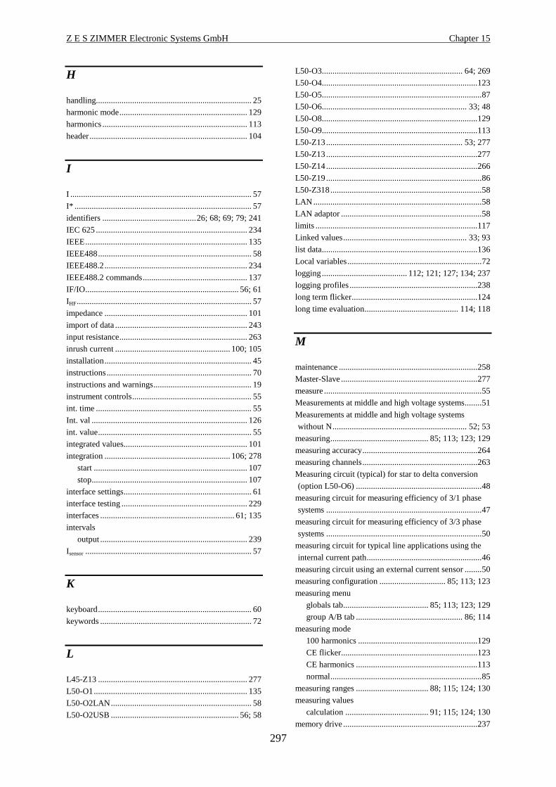
Z E S ZIMMER Electronic Systems GmbH Chapter 15
297
H
handling......................................................................... 25
harmonic mode............................................................ 129
harmonics .................................................................... 113
header.......................................................................... 104
I
I ..................................................................................... 57
I* ................................................................................... 57
identifiers ............................................26; 68; 69; 79; 241
IEC 625 ....................................................................... 234
IEEE............................................................................ 135
IEEE488........................................................................ 58
IEEE488.2................................................................... 234
IEEE488.2 commands................................................. 137
IF/IO........................................................................ 56; 61
IHF.................................................................................. 57
impedance ................................................................... 101
import of data .............................................................. 243
input resistance............................................................ 263
inrush current ...................................................... 100; 105
installation..................................................................... 45
instructions.................................................................... 70
instructions and warnings.............................................. 19
instrument controls........................................................ 55
int. time ......................................................................... 55
Int. val ......................................................................... 126
int. value........................................................................ 55
integrated values.......................................................... 101
integration ........................................................... 106; 278
start ........................................................................ 107
stop......................................................................... 107
interface settings............................................................ 61
interface testing ........................................................... 229
interfaces ............................................................... 61; 135
intervals
output ..................................................................... 239
Isensor.............................................................................. 57
K
keyboard........................................................................ 60
keywords ....................................................................... 72
L
L45-Z13 ...................................................................... 277
L50-O1........................................................................ 135
L50-O2LAN.................................................................. 58
L50-O2USB ............................................................ 56; 58
L50-O3.................................................................. 64; 269
L50-O4.........................................................................123
L50-O5...........................................................................87
L50-O6.................................................................... 33; 48
L50-O8.........................................................................129
L50-O9.........................................................................113
L50-Z13................................................................ 53; 277
L50-Z13.......................................................................277
L50-Z14.......................................................................266
L50-Z19.........................................................................86
L50-Z318.......................................................................58
LAN...............................................................................58
LAN adaptor ..................................................................58
limits ............................................................................117
Linked values.......................................................... 33; 93
list data.........................................................................136
Local variables...............................................................72
logging........................................ 112; 121; 127; 134; 237
logging profiles............................................................238
long term flicker...........................................................124
long time evaluation............................................ 114; 118
M
maintenance .................................................................258
Master-Slave ................................................................277
measure..........................................................................55
Measurements at middle and high voltage systems........51
Measurements at middle and high voltage systems
without N............................................................... 52; 53
measuring.............................................. 85; 113; 123; 129
measuring accuracy......................................................264
measuring channels......................................................263
Measuring circuit (typical) for star to delta conversion
(option L50-O6) ...........................................................48
measuring circuit for measuring efficiency of 3/1 phase
systems .........................................................................47
measuring circuit for measuring efficiency of 3/3 phase
systems .........................................................................50
measuring circuit for typical line applications using the
internal current path......................................................46
measuring circuit using an external current sensor ........50
measuring configuration ............................... 85; 113; 123
measuring menu
globals tab........................................85; 113; 123; 129
group A/B tab .................................................. 86; 114
measuring mode
100 harmonics ........................................................129
CE flicker................................................................123
CE harmonics .........................................................113
normal.......................................................................85
measuring ranges .................................. 88; 115; 124; 130
measuring values
calculation ....................................... 91; 115; 124; 130
memory drive ...............................................................237

Common Index LMG500
298
menu
custom...................................................................... 67
user defined.............................................................. 67
messages
error........................................................................ 244
misc ...........................................53; 56; 60; 259; 262; 277
miscellaneous .............................................................. 245
MotorTorque-SOFT option........................................... 77
N
New menu tab ............................................................... 68
normal measuring mode ................................................ 85
nquery ......................................................................... 136
null modem ................................................................. 234
numerical values............................................................ 84
O
operators........................................................................ 74
option
L50-O1................................................................... 135
L50-O2LAN............................................................. 58
L50-O2USB....................................................... 56; 58
L50-O3............................................................. 64; 269
L50-O4................................................................... 123
L50-O5..................................................................... 87
L50-O6............................................................... 33; 48
L50-O8................................................................... 129
L50-O9................................................................... 113
MotorTorque-SOFT................................................. 77
options........................................................................... 77
options key .................................................................... 67
output devices ............................................................. 238
output formats ............................................................. 240
output intervals............................................................ 239
overload capability ...................................................... 263
P
parallel Port ................................................................. 235
PE.................................................................................. 58
peak-peak value........................................................... 100
physical devices........................................................... 233
plot function ........................................................ 109; 134
Plt ................................................................................ 125
Pmom .......................................................................... 125
power.................... 55; 100; 103; 106; 116; 118; 126; 133
power factor ........................................................ 101; 103
print/log......................................................................... 56
printer....................................................58; 235; 237; 239
printing scripts............................................................... 77
processing signal interface.................................... 64; 269
PS/2 ...............................................................................58
Pst ................................................................................125
Q
qonly ............................................................................135
R
range ..................................................... 88; 115; 124; 130
auto ...........................................................................89
range menu
group A/B tab ...........................................................89
sense/more tab ..........................................................90
ranges.................................................................... 56; 263
reactive energy.................................................... 102; 103
reactive impedance.......................................................101
reactive power..................................................... 101; 103
rear panel .......................................................................56
rectified value ..............................................................100
remarks ..........................................................................75
remote control ..............................................................135
requirements for reference instruments........................259
reset......................................................................... 45; 79
Rsce...............................................................................115
RST Default value........................................................139
S
safety instructions ................................................... 19; 20
sampling.......................................................................263
save/recall ......................................................................56
saving and restoring configurations ...............................79
scope function..............................................................108
SCPI.............................................................................135
script editor ....................................................................69
condition instruction.................................................70
constants ...................................................................71
examples ...................................................................75
expressions ...............................................................71
functions ...................................................................73
general ......................................................................69
grammar....................................................................70
instructions ...............................................................70
keywords...................................................................72
operators ...................................................................74
remarks .....................................................................75
variables....................................................................71
sense/more tab
range menu ...............................................................90
sensor .............................................................................50
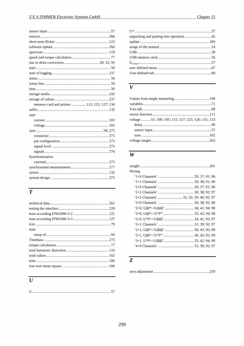
Z E S ZIMMER Electronic Systems GmbH Chapter 15
299
sensor input ................................................................... 57
sensors......................................................................... 266
short term flicker ......................................................... 123
software update ........................................................... 260
spectrum...................................................................... 119
speed and torque calculation ......................................... 77
star to delta conversion......................................28; 33; 93
start................................................................................ 56
start of logging ............................................................ 237
status ............................................................................. 56
status line ...................................................................... 59
stop................................................................................ 56
storage media .............................................................. 242
storage of values.......................................................... 237
memory card and printer ................112; 121; 127; 134
suffix ........................................................................... 135
sum
current .................................................................... 103
voltage.................................................................... 102
sync ....................................................................... 58; 275
connector................................................................ 275
pin configuration.................................................... 275
signal level ............................................................. 275
signals .................................................................... 276
Synchronisation
external................................................................... 275
synchronised measurements ........................................ 277
syntax .......................................................................... 135
system design .............................................................. 275
T
technical data............................................................... 261
testing the interface ..................................................... 229
tests according EN61000-3-2...................................... 121
tests according EN61000-3-3...................................... 127
text................................................................................. 79
time
setup of..................................................................... 60
Timebase ..................................................................... 273
torque calculation.......................................................... 77
total harmonic distortion ............................................. 116
total values .................................................................. 102
trms ............................................................................. 100
true root mean square .................................................. 100
U
U.................................................................................... 57
U* ..................................................................................57
unpacking and putting into operation ............................45
update ..........................................................................260
usage of the manual .......................................................24
USB ...............................................................................58
USB memory stick .........................................................56
Usensor..............................................................................57
user defined menu..........................................................67
User defined tab.............................................................68
V
Values from single measuring......................................100
variables.........................................................................71
Vars tab..........................................................................68
vector function .............................................................111
voltage ..........55; 100; 105; 115; 117; 125; 126; 131; 133
delay .........................................................................90
sensor input...............................................................57
sum .........................................................................102
voltage ranges ..............................................................263
W
weight ..........................................................................261
Wiring
‘1+0 Channels’ ......................................29; 37; 91; 96
‘1+1 Channels’ ......................................29; 38; 91; 96
‘2+0 Channels’ ......................................29; 37; 91; 96
‘2+1 Channels’ ......................................30; 38; 92; 97
‘2+2 Channels’ .......................... 31; 32; 39; 40; 92; 97
‘3+0 Channels’ ......................................30; 38; 92; 96
‘3+0, U∆I*->U ∆I∆’ ............................... 34; 41; 94; 98
‘3+0, U∆I*->U*I*’ ................................ 35; 42; 94; 98
‘3+0, U*I*->U ∆I∆’................................ 34; 41; 93; 97
‘3+1 Channels’ ......................................31; 39; 92; 97
‘3+1, U∆I*->U ∆I∆’ ............................... 36; 43; 95; 99
‘3+1, U∆I*->U*I*’ ................................ 36; 43; 95; 99
‘3+1, U*I*->U ∆I∆’................................ 35; 42; 94; 99
‘4+0 Channels’ ......................................31; 39; 92; 97
Z
zero adjustment ............................................................259

Z E S ZIMMER Electronic Systems GmbH Chapter 16
301
16 Interface command index
*
*CLS ........................................................................... 137
*ESE............................................................................ 137
*ESR?.......................................................................... 138
*IDN?.......................................................................... 138
*IST?........................................................................... 138
*OPC........................................................................... 138
*OPC? ......................................................................... 139
*PRE ........................................................................... 139
*RST ........................................................................... 139
*SRE ........................................................................... 140
*STB?.......................................................................... 140
*TRG........................................................................... 140
*TST?.......................................................................... 140
*WAI........................................................................... 141
/
/nquery/ ....................................................................... 136
/qonly/ ......................................................................... 135
:
:CALCulate
:ENVironment........................................................ 141
:FORMula
[:DEFine].......................................................... 142
:LIMit
:CLASs ............................................................. 142
:DMAX............................................................. 143
:FCURrent ........................................................ 143
:FVERsion ........................................................ 143
:PFACtor .......................................................... 144
:POWer............................................................. 144
:RSCE............................................................... 144
:SYSTem .......................................................... 144
:VERSion.......................................................... 145
:ZREF ............................................................... 145
:ZTESt .............................................................. 145
:DISPlay
:CONTrast.............................................................. 146
:RESet .................................................................... 146
:FETCh
[:SCALar]
:CURRent
:AC?.............................................................147
:CFACtor?....................................................147
:DC?.............................................................148
:FFACtor? ....................................................148
:FSCale?.......................................................148
:INRush? ......................................................148
:MAXPk?.....................................................149
:MINPk?.......................................................149
:PHASe?.......................................................149
:PPEak?........................................................149
:RECTify? ....................................................149
:RUSed?.......................................................150
[:TRMS]?.....................................................150
:CYCLe
:COUNt? ......................................................150
:SNUMber?..................................................151
:TIME?.........................................................151
:DINPut? ...........................................................151
:ENERgy
:APPArent? ..................................................152
:CHARge?....................................................152
:REACtive? ..................................................153
:TIME?.........................................................153
[:ACTive]? ...................................................152
:FLICker
:LTRemain? .................................................156
:PHWave? ....................................................156
:SOURce
:APMoment?...........................................157
:DC?........................................................157
:DELTat? ................................................158
:DMAX? .................................................158
:DTMViolation? .....................................158
:HWTRms? .............................................158
:PLT? ......................................................159
:PMOMentary? .......................................159
:PST? ......................................................159
:RESult?..................................................159
:STATe?.......................................................160
:STRemain?..................................................160
[:EUTest]
:APMoment?...........................................153
:DC?........................................................154
:DELTat? ................................................154
:DMAX? .................................................154
:DTMViolation? .....................................154
Interface command index LMG500
302
:HWTRms? ............................................155
:PLT?...................................................... 155
:PMOMentary?.......................................155
:PST?...................................................... 155
:RESult? ................................................. 156
:FREQuency
:FINPut? ...................................................... 161
:SAMPle? .................................................... 161
[:SSOurce]? ................................................. 161
:HARMonics
:AMPFactor? ............................................... 162
:AMPower? ................................................. 162
:APFactor?................................................... 162
:APOWer? ................................................... 162
:CDResult? .................................................. 163
:CURRent
:AAMPlitude? ........................................ 164
:AFUNdamental? ................................... 164
:AMPLitude?.......................................... 164
:FPRotz?................................................. 165
:FRESult?............................................... 165
:GFResult? ............................................. 165
:IAMPlitude?.......................................... 166
:LIMit? ................................................... 166
:LTResult?.............................................. 166
:OLIMit? ................................................ 167
:PHASe?................................................. 167
:POHarmonic?........................................ 167
:POLimit?............................................... 168
:SAVerage? ............................................ 168
:SMOothed? ........................................... 168
:STATe? ................................................. 168
:THARmonic? ........................................ 169
:THDistort? ............................................ 169
:LTRemain?................................................. 169
:POWer
:ACTive.................................................. 170
:APParent ............................................... 170
:REACtive.............................................. 170
:VOLTage
:IAMPlitude?.......................................... 172
[:VOLTage]
:AMPLitude?.......................................... 171
:GFResult? ............................................. 171
:HWCFactor? .........................................172
:LIMit? ................................................... 172
:LTResult?.............................................. 172
:MAMPlitude? .......................................173
:MAXCfactor?........................................173
:MAXPhi?.............................................. 173
:MINCfactor? ......................................... 173
:MINPhi? ............................................... 174
:OLIMit? ................................................ 174
:PHASe?................................................. 174
:PPHase? ................................................ 174
:STATe?..................................................175
:THDistort?.............................................175
:POWer
:AACTive? ...................................................176
:AAPParent? ................................................176
:APParent? ...................................................176
:AREactive? .................................................177
:FSCale?.......................................................177
:ICAPacity?..................................................177
:PFACtor? ....................................................177
:PHASe?.......................................................178
:REACtive? ..................................................178
[:ACTive]? ...................................................176
:RESistance
:ASResist?....................................................178
:IMPedance? ................................................179
:RSIMpedance?............................................179
:SSYStem? ........................................................179
:TRANsient
:STATe?.......................................................179
:VARiable?........................................................180
:VNAMe?..........................................................180
[:VOLTage]
:AC?.............................................................181
:AINPut? ......................................................181
:CFACtor?....................................................181
:DC?.............................................................181
:FFACtor? ....................................................182
:FSCale?.......................................................182
:MAXPk?.....................................................182
:MINPk?.......................................................182
:PHASe?.......................................................183
:PPEak?........................................................183
:RECTify? ....................................................183
:RUSed?.......................................................183
[:TRMS]?.....................................................183
:FORMat
:DATA....................................................................184
:GTL ............................................................................227
:INITiate
:CONTinuous .........................................................185
:COPY ....................................................................185
:IMMediate.............................................................186
:INPut
:COUPling..............................................................187
:INSTrument
:SELect ...................................................................187
:LEN ............................................................................227
:MEMory
:FREeze ..................................................................188
:SSIZe.....................................................................188
:READ
[:SCALar]
:CURRent
:CFACtor?....................................................147
Z E S ZIMMER Electronic Systems GmbH Chapter 16
303
:DC? ............................................................ 148
:FFACtor?.................................................... 148
:FSCale? ...................................................... 148
:INRush? ..................................................... 148
:MAXPk? .................................................... 149
:MINPk?...................................................... 149
:PHASe?...................................................... 149
:PPEak? ....................................................... 149
:RECTify? ................................................... 149
:RUSed? ...................................................... 150
[:TRMS]? .................................................... 150
:CYCLe
:COUNt?...................................................... 150
:SNUMber? ................................................. 151
:TIME? ........................................................ 151
:DINPut?........................................................... 151
:ENERgy
:APParent?................................................... 152
:CHARge? ................................................... 152
:REACtive? ................................................. 153
:TIME? ........................................................ 153
[:ACTive]? .................................................. 152
:FLICker
:LTRemain?................................................. 156
:PHWave?.................................................... 156
:SOURce
:APMoment? .......................................... 157
:DC?....................................................... 157
:DELTat?................................................ 158
:DMAX? ................................................ 158
:DTMViolation?.....................................158
:HWTRms? ............................................158
:PLT?...................................................... 159
:PMOMentary?.......................................159
:PST?...................................................... 159
:RESult? ................................................. 159
:STATe? ...................................................... 160
:STRemain?................................................. 160
[:EUTest]
:APMoment? .......................................... 153
:DC?....................................................... 154
:DELTat?................................................ 154
:DMAX? ................................................ 154
:DTMViolation?.....................................154
:HWTRms? ............................................155
:PLT?...................................................... 155
:PMOMentary?.......................................155
:PST?...................................................... 155
:RESult? ................................................. 156
:FREQuency
:FINPut? ...................................................... 161
:SAMPle? .................................................... 161
[:SSOurce]? ................................................. 161
:HARMonics
:AMPFactor? ............................................... 162
:AMPower?..................................................162
:APFactor? ...................................................162
:APOWer?....................................................162
:CDResult?...................................................163
:CURRent
:AAMPlitude?.........................................164
:AFUNdamental? ....................................164
:AMPLitude? ..........................................164
:FPRotz? .................................................165
:FRESult? ...............................................165
:GFResult? ..............................................165
:IAMPlitude? ..........................................166
:LIMit?....................................................166
:LTResult? ..............................................166
:OLIMit?.................................................167
:PHASe? .................................................167
:POHarmonic? ........................................167
:POLimit? ...............................................168
:SAVerage?.............................................168
:SMOothed?............................................168
:STATe?..................................................168
:THARmonic?.........................................169
:THDistort?.............................................169
:LTRemain? .................................................169
:VOLTage
:IAMPlitude? ..........................................172
[:VOLTage]
:AMPLitude? ..........................................171
:GFResult? ..............................................171
:HWCFactor?..........................................172
:LIMit?....................................................172
:LTResult? ..............................................172
:MAMPlitude?........................................173
:MAXCfactor? ........................................173
:MAXPhi?...............................................173
:MINCfactor?..........................................173
:MINPhi? ................................................174
:OLIMit?.................................................174
:PHASe? .................................................174
:PPHase?.................................................174
:STATe?..................................................175
:THDistort?.............................................175
POWer
: APParent?.............................................170
:ACTive?.................................................170
:REACtive?.............................................170
:POWer
:AACTive? ...................................................176
:AAPParent? ................................................176
:APParent? ...................................................176
:AREactive? .................................................177
:FSCale?.......................................................177
:ICAPacity?..................................................177
:PFACtor? ....................................................177
:PHASe?.......................................................178

Interface command index LMG500
304
:REACtive? ................................................. 178
[:ACTive]? .................................................. 176
:RESistance
:ASResist? ................................................... 178
:IMPedance?................................................ 179
:RSIMpedance? ........................................... 179
:SSYStem?........................................................ 179
:TRANsient
:STATe? ...................................................... 179
:VARiable? ....................................................... 180
:VNAMe? ......................................................... 180
[:VOLTage]
:AC? ............................................................ 181
:AINPut? ..................................................... 181
:CFACtor? ................................................... 181
:DC? ............................................................ 181
:FFACtor?.................................................... 182
:FSCale? ...................................................... 182
:MAXPk? .................................................... 182
:MINPk?...................................................... 182
:PHASe?...................................................... 183
:PPEak? ....................................................... 183
:RECTify? ................................................... 183
:RUSed? ...................................................... 183
[:TRMS]? .................................................... 183
:SENSe
:AINPut
:DIFFerential .................................................... 189
:FSCale ............................................................. 189
:ZERO .............................................................. 189
:ARON................................................................... 190
:AVERage
:COUNt............................................................. 190
:CURRent
:DELay.............................................................. 191
:DETector ......................................................... 191
:IDENtify? ........................................................ 192
:RANGe
:AUTO......................................................... 192
:LINTern?.................................................... 193
[:UPPer] ...................................................... 193
:SCALe ............................................................. 193
:FILTer
:AFILter ............................................................ 193
[:LPASS]
[:STATe] ..................................................... 194
:FINPut
:SCALe ............................................................. 195
:FLICker
:PERiods........................................................... 196
:STIMe.............................................................. 196
:HARMonics
:FDIV................................................................ 197
:ISTart............................................................... 197
:REFerence ....................................................... 197
:SMOoth............................................................198
:TIME................................................................198
:INTegral
:DATE...............................................................199
:INTerval ...........................................................199
:MODE..............................................................199
:STATe? ............................................................199
:TIME................................................................200
:RPValues...............................................................200
:SWEep
:TIME................................................................201
:TRANsient
:ACRegister.......................................................201
:ALIMit .............................................................202
:BLIMit .............................................................202
:DURation .........................................................202
:FUNCtion.........................................................202
:OCRegister.......................................................203
:SIGNal .............................................................203
:VOLTage
:DELay ..............................................................204
:DETector..........................................................204
:IDENtify...........................................................204
:RANGe
:AUTO .........................................................205
:LINTern? ....................................................205
[:UPPer] .......................................................206
:SCALe..............................................................206
:WAVeform
:DIVision...........................................................206
:IUPDate............................................................207
:SATRigger?......................................................207
:SBTRigger?......................................................207
:SCTRigger?......................................................208
:SRATe?............................................................208
:WAVE?............................................................208
:WIRing ..................................................................209
:ZPReject ................................................................209
:SOURce
:DIGital
:CONDition.......................................................210
:LIMit ................................................................211
:VALue..............................................................211
:VOLTage
:SCALe
:FSCale.........................................................211
:ZERO..........................................................212
:VALue..............................................................212
:STATus
:OPERation
:CONDition? .....................................................212
:ENABle............................................................213
:NTRansition .....................................................213
:PTRansition......................................................213
[:EVENt]? .........................................................213

Z E S ZIMMER Electronic Systems GmbH Chapter 16
305
:PRESet.................................................................. 214
:QUEStionable
:CONDition?..................................................... 214
:ENABle ........................................................... 214
:NTRansition .................................................... 215
:PTRansition..................................................... 215
[:EVENt]?......................................................... 215
:SYSTem
:BEEPer
:IMMediate ....................................................... 216
:DATE.................................................................... 216
:ERRor
:ALL?................................................................ 217
:COUNt?........................................................... 218
[:NEXT]?.......................................................... 218
:HELP
:HEADers?........................................................ 219
:SHEaders? ....................................................... 219
:KEY...................................................................... 219
:LANGuage............................................................ 220
:OPTions? .............................................................. 220
:PHEader................................................................ 221
:TIME .................................................................... 221
:VERSion? ............................................................. 221
:TRIGger
:ACTion ................................................................. 222
:ICURrent............................................................... 222
:INTerval
:RESet............................................................... 223
:STARt.............................................................. 223
:STOP ............................................................... 223
:TREStart .......................................................... 224
:TSTop.............................................................. 224
:TRANsient
:CONTrol.......................................................... 226
[:SEQuence]
:DEModulator................................................... 224
:HPASs ............................................................. 225
:LPASs.............................................................. 225
:SOURce........................................................... 226
<
<list> data.................................................................... 136
A
AC
current .................................................................... 147
voltage.................................................................... 181
action........................................................................... 222
active
energy..................................................................... 152
power ..................................................................... 176
active power
harmonics ...............................................................170
active serial resistance..................................................178
actualisation
measuring values ........................................... 185; 186
AIDI.............................................................................189
AIHI.............................................................................189
AILO............................................................................189
Ain ...............................................................................181
AIVA?..........................................................................181
amplitude
current harmonics ...................................................164
voltage harmonics...................................................171
analogue input
differential inputs....................................................189
full scale..................................................................189
voltage ....................................................................181
zero position ...........................................................189
analogue output
full scale..................................................................211
zero position ...........................................................212
analogue outputs
value .......................................................................212
AND condition
transients.................................................................201
anti-aliasing..................................................................193
AOHI ...........................................................................211
AOIX ...........................................................................212
AOLO ..........................................................................212
apparent
energy .....................................................................152
power ......................................................................176
apparent power
harmonics ...............................................................170
ARON..........................................................................190
AVER ..........................................................................190
average.........................................................................190
average active power....................................................176
average amplitude
current harmonics ...................................................164
average apparent power ...............................................176
average reactive power.................................................177
averaged momentary flicker level ....................... 153; 157
B
BEEP ...........................................................................216
beeper...........................................................................216
C
Calculations
environment............................................................141
capacitive .....................................................................177
Interface command index LMG500
306
change command set ................................................... 220
charge.......................................................................... 152
class D result ............................................................... 163
clear
error/event queue ................................................... 137
event registers ........................................................ 137
command set
change .................................................................... 220
condition
digital outputs ........................................................ 210
CONT.......................................................................... 185
continuous execution................................................... 185
contrast........................................................................ 146
control
transient.................................................................. 226
COPY.......................................................................... 185
COUNT? ..................................................................... 150
counter
measuring cycle...................................................... 150
coupling
signal...................................................................... 187
crest factor................................................................... 172
current .................................................................... 147
maximum ............................................................... 173
minimum................................................................ 173
voltage.................................................................... 181
current
AC.......................................................................... 147
autorange................................................................ 192
crest factor.............................................................. 147
DC.......................................................................... 148
fluctuating harmonics result ................................... 165
form factor ............................................................. 148
full scale................................................................. 148
harmonic phases..................................................... 167
harmonics amplitude.............................................. 164
harmonics average amplitude................................. 164
harmonics limit ...................................................... 166
harmonics maximum duration................................ 165
harmonics result ............................................. 166; 167
inrush ..................................................................... 148
interharmonics........................................................ 166
maximum ............................................................... 149
maximum averaged fundamental............................ 164
minimum................................................................ 149
partial odd harmonic .............................................. 167
peak peak ............................................................... 149
phase angle............................................................. 149
range ...................................................................... 193
range usage............................................................. 150
rectified .................................................................. 149
reset inrush............................................................. 222
scaling .................................................................... 193
smoothed averaged harmonic................................. 168
smoothed harmonic................................................ 168
THD........................................................................169
total harmonic.........................................................169
trigger inrush ..........................................................222
TRMS .....................................................................150
current input
delay .......................................................................191
current sensor
identify....................................................................192
CYCL...........................................................................201
cycle.............................................................................201
sample counter........................................................151
cycle time.....................................................................201
CYCR?.........................................................................151
D
d(t) ...................................................................... 154; 158
data output format........................................................184
date ..............................................................................216
start energy .............................................................199
system.....................................................................216
DC....................................................................... 154; 157
current.....................................................................148
voltage ....................................................................181
dcl ................................................................................154
dcs................................................................................157
Delay current input ......................................................191
Delay voltage input ......................................................204
demodulator
sync.........................................................................224
device
reset ........................................................................139
differential analogue inputs..........................................189
DIFQ? ..........................................................................161
DIFS ............................................................................195
DigFrq..........................................................................161
digital inputs ................................................................151
digital outputs
condition.................................................................210
limits.......................................................................211
value .......................................................................211
display
contrast ...................................................................146
default values..........................................................146
reset ........................................................................146
DISR............................................................................146
DIST?...........................................................................151
dmax ................................................................... 154; 158
dmax limit ....................................................................143
dmaxl ...........................................................................154
dmaxs...........................................................................158
DOCO..........................................................................210
DOIX ...........................................................................211
DOLI............................................................................211

Z E S ZIMMER Electronic Systems GmbH Chapter 16
307
dtl ................................................................................ 154
dts................................................................................ 158
E
EDIT ........................................................................... 145
edition
flicker standard....................................................... 143
harmonic standard.................................................. 145
EI?............................................................................... 152
energy
active...................................................................... 152
apparent.................................................................. 152
reactive................................................................... 153
reset........................................................................ 223
start ........................................................................ 223
start date................................................................. 199
start time ................................................................ 200
state ........................................................................ 199
stop......................................................................... 223
time interval ........................................................... 199
ENV ............................................................................ 141
environment ................................................................ 141
EP................................................................................ 152
EP?.............................................................................. 152
EQ ............................................................................... 153
EQ? ............................................................................. 153
ERR?........................................................................... 218
ERRALL? ................................................................... 217
ERRCNT? ................................................................... 218
error
oldest...................................................................... 218
error/event queue
clear........................................................................ 137
errors ........................................................................... 217
number of............................................................... 218
ES................................................................................ 152
ES?.............................................................................. 152
EVAL.......................................................................... 142
evaluation
harmonics............................................................... 142
event duration transients ............................................. 202
event registers
clear........................................................................ 137
Event Status
Enable Register ...................................................... 137
Register .................................................................. 138
example
basic ....................................................................... 227
SCPI....................................................................... 229
SHORT .................................................................. 231
execution
continuous.............................................................. 185
external shunt input..................................................... 191
F
f....................................................................................161
FAAF ...........................................................................193
FDIV............................................................................197
FILT.............................................................................194
filter .............................................................................194
anti-aliasing ............................................................193
FLCF?..........................................................................172
FLCN? .........................................................................173
FLCX? .........................................................................173
FLDC? .........................................................................154
FLDL ...........................................................................143
FLDT?..........................................................................154
FLDX?.........................................................................154
flicker
averaged momentary level ............................. 153; 157
d(t) ................................................................. 154; 158
dc ................................................................... 154; 157
dmax .............................................................. 154; 158
half wave TRMS............................................ 155; 158
momentary level ............................................ 155; 159
periods ....................................................................196
Plt .................................................................. 155; 159
Pst .................................................................. 155; 159
remaining long time................................................156
remaining short time...............................................160
result .............................................................. 156; 159
short term measuring time ......................................196
start .........................................................................223
state.........................................................................160
stop .........................................................................223
Zref .........................................................................145
Ztest ........................................................................145
flicker standard
version, edition .......................................................143
FlkPer ..........................................................................196
FLLT?..........................................................................155
FLMO? ........................................................................153
FLMS?.........................................................................155
FLMV? ........................................................................154
FLPH?..........................................................................156
FLPN?..........................................................................174
FLPS............................................................................196
FLPX?..........................................................................173
FLRE?..........................................................................156
FLRM?.........................................................................155
FLST? ..........................................................................155
FLTR?..........................................................................156
FLUP?..........................................................................174
FNRM..........................................................................143
FORM..........................................................................142
form factor
current.....................................................................148
voltage ....................................................................182
Interface command index LMG500
308
format
data output ............................................................. 184
Formula Editor ............................................................ 142
environment ........................................................... 141
freezes
scope ...................................................................... 188
FREQ?......................................................................... 161
frequency
processing signal interface ..................................... 161
sample .................................................................... 161
synchronisation source........................................... 161
frequency divider ratio ................................................ 197
frequency input
scaling .................................................................... 195
FRMT.......................................................................... 184
FRZ ............................................................................. 188
FSDC?......................................................................... 157
FSDT?......................................................................... 158
FSDX?......................................................................... 158
FSI?............................................................................. 148
FSLT?.......................................................................... 159
FSMO?........................................................................ 157
FSMS?......................................................................... 159
FSMV?........................................................................ 158
FSP?............................................................................ 177
FSRE? ......................................................................... 159
FSRM? ........................................................................ 158
FSST?.......................................................................... 159
FSTA? ......................................................................... 160
FSTR? ......................................................................... 160
FSU? ........................................................................... 182
FTIM........................................................................... 196
full scale
analogue input........................................................ 189
analogue output...................................................... 211
current .................................................................... 148
power ..................................................................... 177
voltage.................................................................... 182
function
transients ................................................................ 202
fundamental current
harmonic limits ...................................................... 143
G
GFRQ? ........................................................................ 208
GMEM ........................................................................ 188
GMUL......................................................................... 206
GTL............................................................................. 227
H
half wave
crest factor ..............................................................172
half wave power...........................................................156
half wave TRMS................................................. 155; 158
harmonic limit
partial odd...............................................................168
harmonic limits
fundamental current ................................................143
power ......................................................................144
power factor............................................................144
rsce..........................................................................144
harmonic standard
version, edition .......................................................145
harmonics
active power............................................................170
apparent power .......................................................170
average current amplitude.......................................164
class D result...........................................................163
current amplitude....................................................164
current check result........................................ 165; 168
current limits...........................................................166
current phases .........................................................167
current result.................................................. 166; 167
evaluation ...............................................................142
fluctuating current result.........................................165
interharmonics current ............................................166
interharmonics voltage............................................172
maximum amplitude voltage...................................173
maximum averaged fundamental current ................164
maximum duration..................................................165
measuring time........................................................198
partial odd current...................................................167
reactive power.........................................................170
remaining long time................................................169
smoothed averaged current ....................................168
smoothed current ....................................................168
smoothing ...............................................................198
THD current............................................................169
THD voltage ...........................................................175
total current.............................................................169
voltage amplitude ...................................................171
voltage check results...................................... 171; 175
voltage limit............................................................172
voltage phases.........................................................174
voltage result ................................................. 172; 174
HEAD? ........................................................................219
headers
SCPI .......................................................................219
SHORT...................................................................219
HENS?.........................................................................163
HFMX?........................................................................165
HIAM?.........................................................................164
HIAS? ..........................................................................168
HIAV? .........................................................................164
HIFL?...........................................................................165
HIFM? .........................................................................164
Z E S ZIMMER Electronic Systems GmbH Chapter 16
309
HIGF?.......................................................................... 165
high pass
sync ........................................................................ 225
HIHD?......................................................................... 169
HILM?......................................................................... 166
HILT?.......................................................................... 166
HIMA? ........................................................................ 168
HIOV?......................................................................... 167
HIPH? ......................................................................... 167
HIST?.......................................................................... 168
HIZA? ......................................................................... 166
HLIP?.......................................................................... 168
HLTR? ........................................................................ 169
HNRZ.......................................................................... 197
HPAM? ....................................................................... 170
HPAV?........................................................................ 162
HPFA?......................................................................... 162
HPFM?........................................................................ 162
HPM?.......................................................................... 162
HPOC? ........................................................................ 167
HQAM?....................................................................... 170
HREF .......................................................................... 197
HSAM? ....................................................................... 170
HTHC?........................................................................ 169
HTIM .......................................................................... 198
HUAM?....................................................................... 171
HUGF?........................................................................ 171
HUHD? ....................................................................... 175
HULM? ....................................................................... 172
HULT? ........................................................................ 172
HUMX?....................................................................... 173
HUOV? ....................................................................... 174
HUPH?........................................................................ 174
HUST? ........................................................................ 175
HUZA?........................................................................ 172
I
Iac................................................................................ 147
IAC?............................................................................ 147
IAM............................................................................. 192
Iaver ............................................................................ 164
Icf ................................................................................ 147
ICF?............................................................................. 147
Idc ............................................................................... 148
IDC?............................................................................ 148
identification ............................................................... 138
Identify current sensor................................................. 192
Identify voltage sensor ................................................ 204
IDLY........................................................................... 191
IDNI? .......................................................................... 192
IDNU........................................................................... 204
IEXT ........................................................................... 191
Iff................................................................................. 148
IFF?............................................................................. 148
Ih..................................................................................164
IILS..............................................................................193
Iinr ...............................................................................148
IINR? ...........................................................................148
IL .................................................................................166
IMAX?.........................................................................149
IMIN? ..........................................................................149
impedance....................................................................179
reactive serial ..........................................................179
reference .................................................................145
test ..........................................................................145
INCA?..........................................................................177
Individual Status Query ...............................................138
inductive ......................................................................177
INIM ............................................................................186
initiate measuring................................................ 185; 186
inrush current...............................................................148
trigger .....................................................................222
INTD............................................................................199
integration mode ..........................................................199
interharmonics
current.....................................................................166
start .........................................................................197
voltage ....................................................................172
internal shunt input ......................................................191
interval
energy .....................................................................199
INTI .............................................................................199
INTM...........................................................................199
INTR? ..........................................................................153
INTS?...........................................................................199
INTT ............................................................................200
IP .................................................................................167
IPHI?............................................................................149
Ipkn..............................................................................149
Ipkp..............................................................................149
Ipohc............................................................................167
Ipp................................................................................149
IPP? .............................................................................149
IREC? ..........................................................................149
Irect..............................................................................149
IRNG ...........................................................................193
ISCA............................................................................193
Iscal..............................................................................193
ISO...............................................................................143
Ithc...............................................................................169
Ithd...............................................................................169
Itrms.............................................................................150
ITRMS? .......................................................................150
K
KEY.............................................................................219

Interface command index LMG500
310
L
LEN............................................................................. 227
limit
current harmonics................................................... 166
damx....................................................................... 143
partial odd harmonic .............................................. 168
voltage harmonics .................................................. 172
limits
digital outputs ........................................................ 211
transients ................................................................ 202
list
ranges
current............................................................... 193
voltage .............................................................. 205
list data ........................................................................ 136
local state..................................................................... 227
low pass
sync ........................................................................ 225
M
maximum
averaged fundamental current ................................ 164
current .................................................................... 149
voltage.................................................................... 182
maximum amplitude voltage harmonics...................... 173
maximum crest factor
voltage.................................................................... 173
maximum duration
current harmonics................................................... 165
maximum phase
peak value voltage.................................................. 173
maximum smoothed power ......................................... 162
maximum smoothed power factor ............................... 162
measuring cycle
real time ................................................................. 151
measuring cycle counter .............................................. 150
measuring mode .......................................................... 187
measuring time
harmonics............................................................... 198
short term flicker.................................................... 196
measuring values
actualisation ................................................... 185; 186
memory size ................................................................ 188
minimum
current .................................................................... 149
voltage.................................................................... 182
minimum crestfactor
voltage.................................................................... 173
minimum phase
peak value voltage.................................................. 174
MODE......................................................................... 187
integration .............................................................. 199
measuring ...............................................................187
momentary flicker level ...................................... 155; 159
averaged......................................................... 153; 157
Mtime...........................................................................151
N
new information about waveform ................................207
nquery ..........................................................................136
number of errors...........................................................218
NVAR? ........................................................................180
O
oldest error...................................................................218
Operation Status
Condition Register..................................................212
Enable Register.......................................................213
Event Register.........................................................213
Negative Transition Register ..................................213
Positive Transition Register....................................213
options
installed ..................................................................220
OvrI..............................................................................150
OVRI?..........................................................................150
OvrU ............................................................................183
OVRU? ........................................................................183
P
P...................................................................................176
P? .................................................................................176
Parallel Poll Enable Register .......................................139
Partial odd harmonic current........................................167
Partial odd harmonic limit ...........................................168
peak peak
current.....................................................................149
voltage ....................................................................183
periods
flicker......................................................................196
PF.................................................................................177
PF?...............................................................................177
PFSO............................................................................144
Ph.................................................................................170
phantom values
reject .......................................................................200
phase
current harmonics ...................................................167
Fresnel ....................................................................197
maximum peak voltage ...........................................173
minimum peak voltage............................................174
reference .................................................................197

Z E S ZIMMER Electronic Systems GmbH Chapter 16
311
voltage harmonics .................................................. 174
phase angle.................................................................. 178
current ............................................................ 149; 183
voltage peak ........................................................... 174
PHDR.......................................................................... 221
PHI .............................................................................. 178
PHI? ............................................................................ 178
Plt ........................................................................ 155; 159
Pltl............................................................................... 155
Plts .............................................................................. 159
Pm ............................................................................... 176
PM?............................................................................. 176
Pml .............................................................................. 155
Pmoml ......................................................................... 153
Pmoms......................................................................... 157
Pms.............................................................................. 159
power
active...................................................................... 176
apparent.................................................................. 176
average active......................................................... 176
average apparent .................................................... 176
average reactive...................................................... 177
capacitive ............................................................... 177
full scale................................................................. 177
half wave................................................................ 156
harmonic limits ...................................................... 144
inductive ................................................................ 177
maximum smoothed ............................................... 162
reactive................................................................... 178
smoothed................................................................ 162
power factor ................................................................ 177
harmonic limits ...................................................... 144
maximum smoothed ............................................... 162
smoothed................................................................ 162
PRES........................................................................... 214
Preset
operation and query registers ................................. 214
printer header .............................................................. 221
processing signal interface
frequency................................................................ 161
PSO ............................................................................. 144
Pst........................................................................ 155; 159
Pstl .............................................................................. 155
Psts .............................................................................. 159
Q
q .......................................................................... 152; 178
Q?................................................................................ 178
Qh................................................................................ 170
Qm............................................................................... 177
QM? ............................................................................ 177
qonly ........................................................................... 135
Questionable Status
Condition Register ................................................. 214
Enable Register.......................................................214
Event Register.........................................................215
Negative Transition Register ..................................215
Positive Transition Register....................................215
R
range
current.....................................................................193
voltage ....................................................................206
range usage
current.....................................................................150
voltage ....................................................................183
ranges
voltage ....................................................................205
ratio
frequency divider ....................................................197
reactive
energy .....................................................................153
reactive power..............................................................178
harmonics ...............................................................170
reactive serial impedance .............................................179
real measuring time......................................................151
rectified
current.....................................................................149
voltage ....................................................................183
reference
phase.......................................................................197
reference impedance ....................................................145
register
Event Status............................................................138
Event Status Enable................................................137
Operation Status Enable .........................................213
Operation Status Event ...........................................213
Operation Status Negative Transition.....................213
Operation Status Positive Transition ......................213
Parallel Poll Enable ................................................139
Preset
operation and query...........................................214
Questionable Status Condition ...............................214
Questionable Status Enable ....................................214
Questionable Status Event ......................................215
Questionable Status Negative Transition................215
Questionable Status Positive Transition .................215
Service Request Enable ..........................................140
Status Byte..............................................................140
reject phantom values ..................................................200
remaining long time
flicker......................................................................156
harmonics ...............................................................169
remaining short time ....................................................160
remote - operation........................................................227
remote state..................................................................227
reset..............................................................................223
device......................................................................139

Interface command index LMG500
312
display.................................................................... 146
energy..................................................................... 223
resistance
active serial ............................................................ 178
impedance .............................................................. 179
result
class D.................................................................... 163
current fluctuating harmonics ................................ 165
current harmonics........................................... 166; 167
flicker ..................................................................... 159
flicker measuring.................................................... 156
harmonics current check ................................ 165; 168
harmonics voltage check ................................ 171; 175
voltage harmonics .......................................... 172; 174
RLS? ........................................................................... 179
RngI............................................................................. 193
RngU........................................................................... 206
RSCE........................................................................... 144
Rser ............................................................................. 178
RSER?......................................................................... 178
running integration time.............................................. 153
S
S .................................................................................. 176
S? ................................................................................ 176
SACT .......................................................................... 207
sample counter
trigger..................................................................... 208
sample values .............................................................. 208
memory size ........................................................... 188
saving ratio............................................................. 208
sample values after trigger........................................... 207
sample values before trigger........................................ 207
samples per division.................................................... 206
sampling frequency ..................................................... 161
SATR?......................................................................... 207
SBTR?......................................................................... 207
scaling
current .................................................................... 193
frequency input ...................................................... 195
voltage.................................................................... 206
scope
freeze...................................................................... 188
SCPI
example.................................................................. 229
version.................................................................... 221
SCPI headers............................................................... 219
script editor ................................................................. 142
SCTC?......................................................................... 151
SCTT? ......................................................................... 208
self test ........................................................................ 140
sensor
identify current....................................................... 192
identify voltage .......................................................204
sensor input......................................................... 191; 204
Service Request Enable Register .................................140
Sh.................................................................................170
SHEAD? ......................................................................219
SHORT
example...................................................................231
SHORT headers ...........................................................219
short term flicker measuring time ................................196
shunt input
internal/external ......................................................191
signal
transients.................................................................203
signal coupling.............................................................187
Sm................................................................................176
SM?..............................................................................176
SMOO..........................................................................198
smoothed
average harmonic current........................................168
harmonic current.....................................................168
smoothed power...........................................................162
smoothed power factor.................................................162
smoothing
harmonics ...............................................................198
SMPL?.........................................................................161
SOC?............................................................................212
SOE?............................................................................213
SOEN...........................................................................213
SONT...........................................................................213
SOPT ...........................................................................213
SQC?............................................................................214
SQE?............................................................................215
SQEN...........................................................................214
SQNT...........................................................................215
SQPT ...........................................................................215
START.........................................................................223
energy .....................................................................223
flicker......................................................................223
start date
energy .....................................................................199
start time energy...........................................................200
startup current ..............................................................148
reset ........................................................................222
state
energy .....................................................................199
flicker......................................................................160
local ........................................................................227
remote.....................................................................227
transients?...............................................................179
Status Byte Register.....................................................140
STOP ...........................................................................223
energy .....................................................................223
flicker......................................................................223
transients.................................................................224
supply system...................................................... 144; 179
Z E S ZIMMER Electronic Systems GmbH Chapter 16
313
SYNC.......................................................................... 226
synchronisation
demodulator ........................................................... 224
high pass ................................................................ 225
low pass.................................................................. 225
source..................................................................... 226
synchronisation source
frequency................................................................ 161
syntax .......................................................................... 135
SYSD .......................................................................... 144
system
supply............................................................. 144; 179
system date .................................................................. 216
system time.................................................................. 221
T
TACR.......................................................................... 201
TCTL........................................................................... 226
TDUR.......................................................................... 202
test impedance............................................................. 145
TFUN .......................................................................... 202
THD
current .................................................................... 169
voltage.................................................................... 175
time ............................................................................. 221
cycle ....................................................................... 201
measuring harmonics ............................................. 198
running integration................................................. 153
short term flicker measuring time........................... 196
start energy............................................................. 200
system .................................................................... 221
time interval
energy..................................................................... 199
TLIA............................................................................ 202
TLIB............................................................................ 202
TOCR.......................................................................... 203
Total harmonic current ................................................ 169
transients
AND condition register.......................................... 201
event duration ........................................................ 202
function .................................................................. 202
limits ...................................................................... 202
OR condition register............................................. 203
signal...................................................................... 203
start ........................................................................ 224
state ........................................................................ 179
stop......................................................................... 224
TRGA.......................................................................... 224
TRGP .......................................................................... 225
TRGT .......................................................................... 225
Trigger......................................................................... 140
demodulator ........................................................... 224
high pass ................................................................ 225
inrush current ......................................................... 222
low pass ..................................................................225
sample counter........................................................208
source......................................................................226
TRMS
current.....................................................................150
half wave........................................................ 155; 158
voltage ....................................................................183
TRST ...........................................................................224
TSRC ...........................................................................203
TSTA?..........................................................................179
TSTP............................................................................224
U
Uac...............................................................................181
UAC?...........................................................................181
UAM............................................................................205
Ucf ...............................................................................181
UCF?............................................................................181
Udc ..............................................................................181
UDC?...........................................................................181
UDLY ..........................................................................204
UEXT...........................................................................204
Uff................................................................................182
UFF? ............................................................................182
Uh ................................................................................171
Uhwl ............................................................................155
Uhws............................................................................158
UILS ............................................................................205
UL................................................................................172
UMax...........................................................................173
UMAX? .......................................................................182
UMIN?.........................................................................182
UP................................................................................174
UPHI? ..........................................................................183
Upkn ............................................................................182
Upkp ............................................................................182
Upp ..............................................................................183
UPP?............................................................................183
UREC?.........................................................................183
Urect ............................................................................183
URNG..........................................................................206
USCA...........................................................................206
Uscal ............................................................................206
Uthd .............................................................................175
Utrms ...........................................................................183
UTRMS?......................................................................183
V
value
analogue outputs.....................................................212
digital outputs .........................................................211
VAR?...........................................................................180

Interface command index LMG500
314
variables ...................................................................... 180
access by name....................................................... 180
version
flicker standard....................................................... 143
harmonic standard.................................................. 145
voltage
AC.......................................................................... 181
analogue input........................................................ 181
autorange................................................................ 205
crest factor.............................................................. 181
DC.......................................................................... 181
form factor ............................................................. 182
full scale................................................................. 182
harmonics amplitude.............................................. 171
harmonics limit ...................................................... 172
harmonics phase..................................................... 174
harmonics result ............................................. 172; 174
interharmonics........................................................ 172
maximum ............................................................... 182
maximum crest factor............................................. 173
maximum harmonics amplitude ............................. 173
maximum phase ..................................................... 173
minimum................................................................ 182
minimum crestfactor .............................................. 173
minimum phase...................................................... 174
peak peak ............................................................... 183
peak phase angle .................................................... 174
phase angle............................................................. 183
range ...................................................................... 206
range usage............................................................. 183
rectified .................................................................. 183
scaling .................................................................... 206
THD ....................................................................... 175
TRMS .................................................................... 183
voltage input................................................................ 204
delay .......................................................................204
voltage sensor
identify....................................................................204
W
Wait .............................................................................141
WAVE?........................................................................208
waveform
new information about............................................207
sample values..........................................................208
sample values after trigger ......................................207
sample values before trigger ...................................207
WIRE...........................................................................209
wiring...........................................................................209
X
Xser..............................................................................179
XSER? .........................................................................179
Z
Z...................................................................................179
Z?.................................................................................179
zero point rejection ......................................................209
zero position
analogue input ........................................................189
analogue output ......................................................212
ZREF ...........................................................................145
ZTST............................................................................145