multi-channel ignition control module - msd performancedocuments.msdperformance.com/42351.pdf ·...
TRANSCRIPT

FACTORY DIRECT PERFORMANCE • 1355 PULLMAN DR., EL PASO, TEXAS 79936 • (915) 858-3365 • FAX (915) 858-3496
Multi-Channel Ignition Control ModulePN 00-00-2530
IMPORTANT: Read these Instructions before attempting the installation!
WARNING:During installation, disconnect the battery cables. When disconnecting the battery, always removethe Negative cable first and install it last.
Parts Included1 - Multi-Channel Ignition Module, PN 00-00-25301 - Wire Terminal Kit
Tools Required1 - Metric Wrench Set1 - Wire Terminal Crimper1 - Heat Gun1 - Metric Allen Wrench Set
MOUNTING THE IGNITIONThe Multi-Channel Ignition module may be mounted in any location except on the engine or
near the exhaust manifold. Excessive heat at these locations may cause damage to the ignition.When selecting a mounting location, make sure the cable assembly will reach the battery, coiland trigger assembly. A stainless steel or aluminum mounting plate with room forcomplimentary components is recommended.IMPORTANT: Do not mount the coil within 6" of the ignition control unit.
WIRINGAll wires must be routed away from direct heat sources and not allowed to rub on any
surface when cutting to desired length. Strip the wire ends to expose the internal strands anduse the supplied solderless/heat shrink connectors (Figure 1).
Figure 1WIRING THE IGNITIONNote: Any unused wires should be capped off to prevent shorting out or from picking up EMI.Note: When used on 1 or 2-cylinder engines, some channel inputs and outputs are not connected,
cap these off.1. Figures 2 and 3 shows the complete wiring diagram for the Multi-Channel Ignition unit for
universal applications. Connect the VIOLET wire to one wire of an On/Off switch (notsupplied). Then connect the other wire of the switch to the positive (+) terminal of thebattery or starter solenoid.
2. Connect the PINK wire to one wire of a normally closed lanyard type kill switch. If not usedseal the end of the wire.

3. Connect the remaining wire of the kill switch to negative (-) terminal of the battery or to anengine ground.
4. To utilize the Holeshot feature, the LIGHT BLUE wire must be connected to one wire of anormally open momentary switch (PN 00-00-0520) then connect the remaining wire of theswitch to the negative (-) battery terminal or to an engine ground.
Note: It is very important that the BLK Ring Lug wire from the coil be attached directly to the engine.
Figure 2 Universal Two Cylinder wiring application.
FACTORY DIRECT PERFORMANCE • 1355 PULLMAN DR., EL PASO, TEXAS 79936 • (915) 858-3365 • FAX (915) 858-3496
2 INSTALLATION INSTRUCTIONS
Figure 3 Universal Three Cylinder Wiring Application.
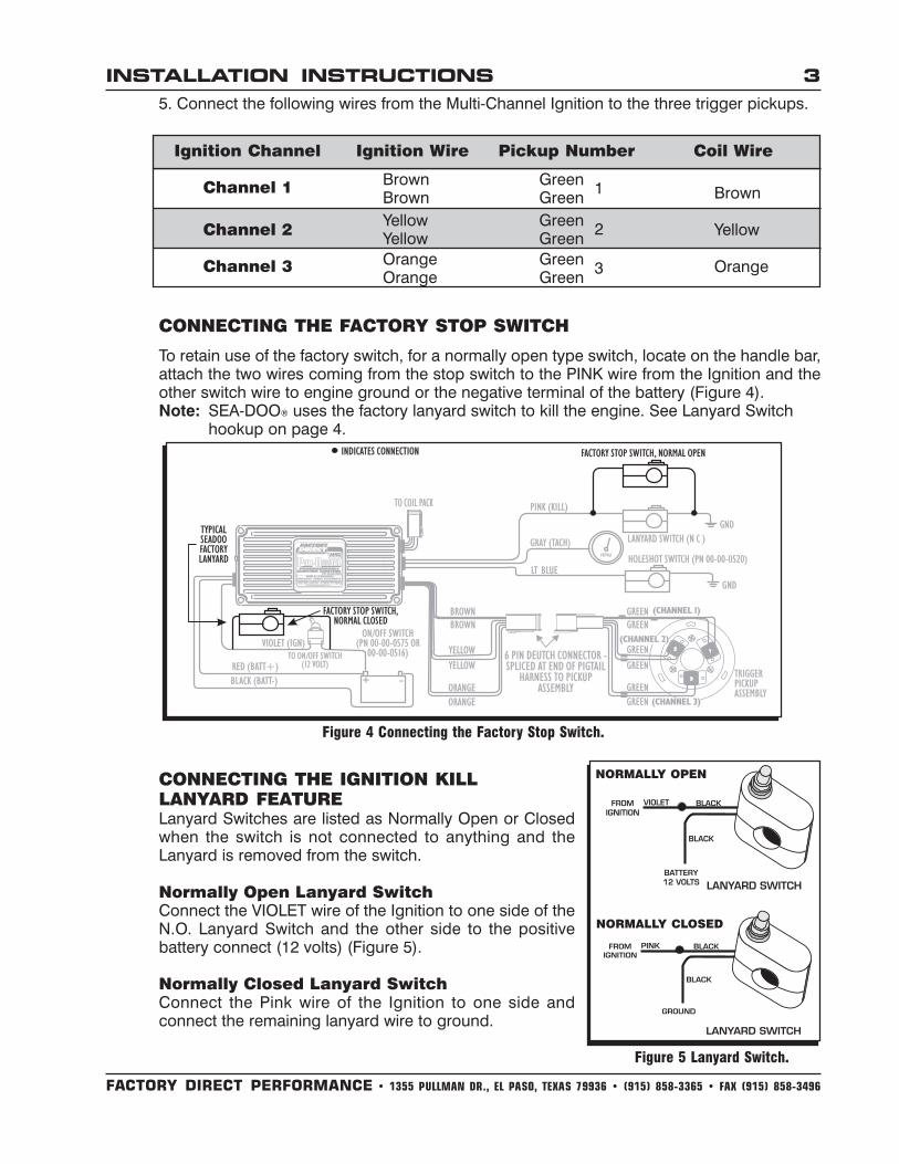
Figure 4 Connecting the Factory Stop Switch.
CONNECTING THE IGNITION KILLLANYARD FEATURELanyard Switches are listed as Normally Open or Closedwhen the switch is not connected to anything and theLanyard is removed from the switch.
Normally Open Lanyard SwitchConnect the VIOLET wire of the Ignition to one side of theN.O. Lanyard Switch and the other side to the positivebattery connect (12 volts) (Figure 5).
Normally Closed Lanyard SwitchConnect the Pink wire of the Ignition to one side andconnect the remaining lanyard wire to ground.
FACTORY DIRECT PERFORMANCE • 1355 PULLMAN DR., EL PASO, TEXAS 79936 • (915) 858-3365 • FAX (915) 858-3496
INSTALLATION INSTRUCTIONS 3
5. Connect the following wires from the Multi-Channel Ignition to the three trigger pickups.
CONNECTING THE FACTORY STOP SWITCH
To retain use of the factory switch, for a normally open type switch, locate on the handle bar,attach the two wires coming from the stop switch to the PINK wire from the Ignition and theother switch wire to engine ground or the negative terminal of the battery (Figure 4).Note: SEA-DOO® uses the factory lanyard switch to kill the engine. See Lanyard Switch
hookup on page 4.
Ignition Channel Ignition Wire Pickup Number Coil Wire
Channel 1
Channel 2
Channel 3
Brown GreenBrown Green 1
Yellow GreenYellow Green 2
Orange GreenOrange Green 3
Brown
Yellow
Orange
Figure 5 Lanyard Switch.
NORMALLY CLOSED
NORMALLY OPEN
FACTORY DIRECT PERFORMANCE • 1355 PULLMAN DR., EL PASO, TEXAS 79936 • (915) 858-3365 • FAX (915) 858-3496
4 INSTALLATION INSTRUCTIONS
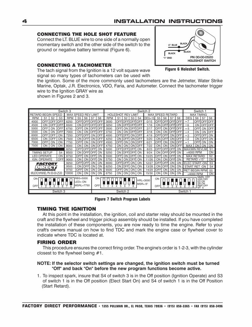
Figure 7 Switch Program Labels
TIMING THE IGNITIONAt this point in the installation, the ignition, coil and starter relay should be mounted in the
craft and the flywheel and trigger pickup assembly should be installed. If you have completedthe installation of these components, you are now ready to time the engine. Refer to yourcraft's owners manual on how to find TDC and mark the engine case or flywheel cover toindicate where TDC is located at.
FIRING ORDERThis procedure ensures the correct firing order. The engine's order is 1-2-3, with the cylinder
closest to the flywheel being #1.
NOTE: If the selector switch settings are changed, the ignition switch must be turned"Off" and back "On" before the new program functions become active.
1. To inspect spark, insure that S4 of switch 3 is in the Off position (Ignition Operate) and S3of switch 1 is in the Off position (Elect Start On) and S4 of switch 1 is in the Off Position(Start Retard).
CONNECTING THE HOLE SHOT FEATUREConnect the LT. BLUE wire to one side of a normally openmomentary switch and the other side of the switch to theground or negative battery terminal (Figure 6).
CONNECTING A TACHOMETERThe tach signal from the Ignition is a 12 volt square wavesignal so many types of tachometers can be used withthe ignition. Some of the more commonly used tachometers are the Jetmeter, Water StrikeMarine, Optak, J.R. Electronics, VDO, Faria, and Autometer. Connect the tachometer triggerwire to the Ignition GRAY wire asshown in Figures 2 and 3.
Figure 6 Holeshot Switch.
FACTORY DIRECT PERFORMANCE • 1355 PULLMAN DR., EL PASO, TEXAS 79936 • (915) 858-3365 • FAX (915) 858-3496
INSTALLATION INSTRUCTIONS 5
WARNING: High voltage will discharge at spark plugs to engine ground. DO NOT TOUCHspark plugs with ignition On.
2. Make sure that the RED wire from the Multi-Channel Ignition is connected to the positiveside of the battery.
3. Remove the spark plugs from the engine, plug them into the spark plug wires and lay theplugs on the cylinder head.
4. Using a Dial Indicator, find Top Dead Center of the #1 cylinder (the front cylinder).5. Rotate the flywheel counterclockwise about 1/4 of a turn.6. Turn the ignition On/Off Switch to the On position and slowly rotate the flywheel clockwise
until the front plug sparks. (Ignore LED at this time and look for spark from the spark plug).Mark the spark plug that fires #1.
6. Continue rotating the crankshaft until the next spark plug fires. Verify cylinder 2 is nearTDC, then mark this spark plug wire #2 and mark the last spark plug wire as #3.
7. If the plugs do not fire in the 1-2-3 order, the wires or the pickups are not installed correctly.Check the wiring to the pickups and make sure the coil #1 terminal is connected to the#1 spark plug.
SETTING THE TIMINGIMPORTANT NOTE: If the selector switch settings are changed, the ignition switch mustbe turned "Off" and back "On" before the new program functions become active.
The Multi-Channel Ignition's innovative design allows you to static time the enginebefore the engine is started.1. Remove the spark plugs from the engine, plug them into the spark plug wires and lay the
plugs on the cylinder head. Insure that S4 of switch 3 is in the On position (LED Operate),then turn the ignition On/Off Switch to the On position.
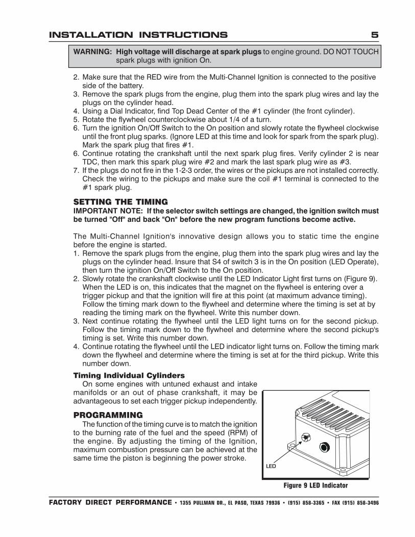
2. Slowly rotate the crankshaft clockwise until the LED Indicator Light first turns on (Figure 9).When the LED is on, this indicates that the magnet on the flywheel is entering over atrigger pickup and that the ignition will fire at this point (at maximum advance timing).Follow the timing mark down to the flywheel and determine where the timing is set at byreading the timing mark on the flywheel. Write this number down.
3. Next continue rotating the flywheel until the LED light turns on for the second pickup.Follow the timing mark down to the flywheel and determine where the second pickup'stiming is set. Write this number down.
4. Continue rotating the flywheel until the LED indicator light turns on. Follow the timing markdown the flywheel and determine where the timing is set at for the third pickup. Write thisnumber down.
Timing Individual CylindersOn some engines with untuned exhaust and intake
manifolds or an out of phase crankshaft, it may beadvantageous to set each trigger pickup independently.
PROGRAMMINGThe function of the timing curve is to match the ignition
to the burning rate of the fuel and the speed (RPM) ofthe engine. By adjusting the timing of the Ignition,maximum combustion pressure can be achieved at thesame time the piston is beginning the power stroke.
Figure 9 LED Indicator

FACTORY DIRECT PERFORMANCE • 1355 PULLMAN DR., EL PASO, TEXAS 79936 • (915) 858-3365 • FAX (915) 858-3496
6 INSTALLATION INSTRUCTIONS
Figure 10 Programming Points
FACTOR ADVANCE FOR RETARD FORCylinder Pressure Low HighRPM Engine Low HighEnergy of Ignition Low HighFuel Octane High LowMixture (Fuel/Air) Rich LeanTemperature Cool HotCombustion Turbulence Low HighLoad Light Heavy
Figure 11 Timing Recommendation Chart
TIPS FOR SETTING YOUR IGNITION TIMING1. Use as much initial
advance as possiblewithout encount-ering excessivestarter load orengine kickback onstarting. Beware ofdetonation whensetting the initialadvance.
Note:With the Start Retard Switch On (S4 of switch 1), the start timing is the trailing edge ofthe magnet approximately 20°. This is recommended for minimum starter loading.
2. Set the timing retard start point as early as possible without sacrificing low RPMperformance.
3. Use the highest retard possible without hurting top end performance.
PROGRAMMING THE IGNITIONThe Ignition produces a computer-generated timing curve. Several programming options
are available to tune the basic timing curve to meet specific engine requirements. The factoryprogram settings are suitable for most watercraft, but changes can be made for specialapplications. Three switches located under the aluminum plate of the MSD Ignition moduleselect the programming options.
IMPORTANT NOTE: If the selector switch settings are changed, the ignition switch mustbe turned "Off" and back "On" before the new program functions become active. Alwaysinstall the aluminum backing plate to seal switches.
Any factor that changes the burning rateof the fuel or the engine speed (RPM)can cause a need for an ignition timingchange. Figure 11 shows some of thefactors that will effect ignition timing.
As you can see from the chart, mostfactors will change throughout therange of engine operation. Timingadjustments must be made tocompensate for these changes.Obviously, a full technical explanationof the correct ignition timing would bevery complicated. The best way to arriveat a suitable timing curve for yourengine is to use the above chart as aguide to compare your enginecombination with.
FACTORY DIRECT PERFORMANCE • 1355 PULLMAN DR., EL PASO, TEXAS 79936 • (915) 858-3365 • FAX (915) 858-3496
INSTALLATION INSTRUCTIONS 7
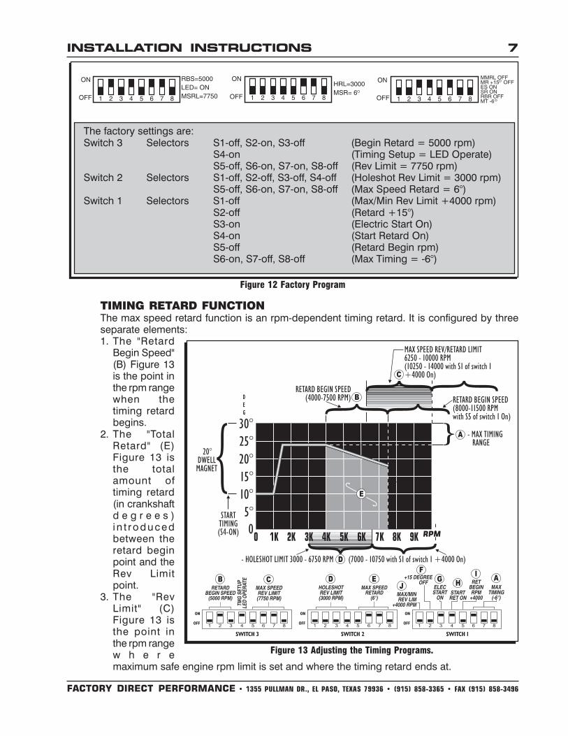
The factory settings are:Switch 3 Selectors S1-off, S2-on, S3-off (Begin Retard = 5000 rpm)
S4-on (Timing Setup = LED Operate)S5-off, S6-on, S7-on, S8-off (Rev Limit = 7750 rpm)
Switch 2 Selectors S1-off, S2-off, S3-off, S4-off (Holeshot Rev Limit = 3000 rpm)S5-off, S6-on, S7-on, S8-off (Max Speed Retard = 6°)
Switch 1 Selectors S1-off (Max/Min Rev Limit +4000 rpm)S2-off (Retard +15°)S3-on (Electric Start On)S4-on (Start Retard On)S5-off (Retard Begin rpm)S6-on, S7-off, S8-off (Max Timing = -6°)
Figure 12 Factory Program
TIMING RETARD FUNCTIONThe max speed retard function is an rpm-dependent timing retard. It is configured by threeseparate elements:1. The "Retard
Begin Speed"(B) Figure 13is the point inthe rpm rangewhen thetiming retardbegins.
2. The "TotalRetard" (E)Figure 13 isthe totalamount oftiming retard(in crankshaftd e g r e e s )i n t roducedbetween theretard beginpoint and theRev Limitpoint.
3. The "RevLimit" (C)Figure 13 isthe point inthe rpm rangew h e r emaximum safe engine rpm limit is set and where the timing retard ends at.
Figure 13 Adjusting the Timing Programs.
FACTORY DIRECT PERFORMANCE • 1355 PULLMAN DR., EL PASO, TEXAS 79936 • (915) 858-3365 • FAX (915) 858-3496
8 INSTALLATION INSTRUCTIONS
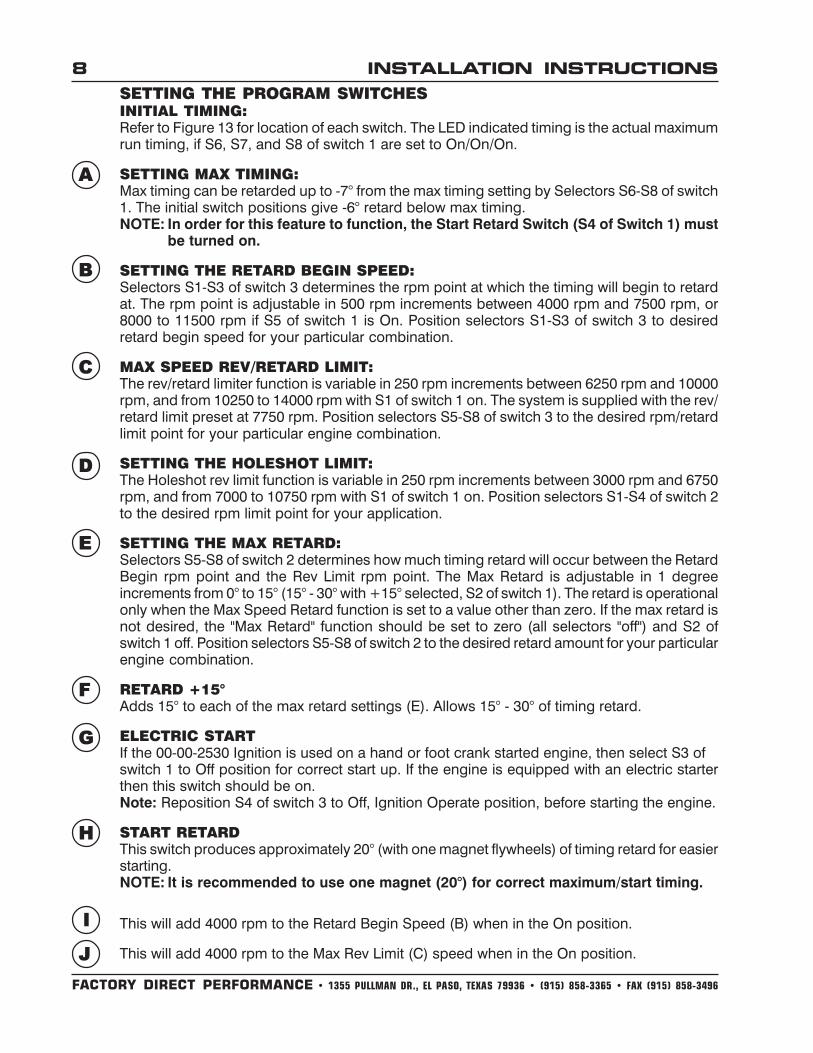
SETTING THE PROGRAM SWITCHESINITIAL TIMING:Refer to Figure 13 for location of each switch. The LED indicated timing is the actual maximumrun timing, if S6, S7, and S8 of switch 1 are set to On/On/On.
SETTING MAX TIMING:Max timing can be retarded up to -7° from the max timing setting by Selectors S6-S8 of switch1. The initial switch positions give -6° retard below max timing.NOTE: In order for this feature to function, the Start Retard Switch (S4 of Switch 1) must
be turned on.
SETTING THE RETARD BEGIN SPEED:Selectors S1-S3 of switch 3 determines the rpm point at which the timing will begin to retardat. The rpm point is adjustable in 500 rpm increments between 4000 rpm and 7500 rpm, or8000 to 11500 rpm if S5 of switch 1 is On. Position selectors S1-S3 of switch 3 to desiredretard begin speed for your particular combination.
MAX SPEED REV/RETARD LIMIT:The rev/retard limiter function is variable in 250 rpm increments between 6250 rpm and 10000rpm, and from 10250 to 14000 rpm with S1 of switch 1 on. The system is supplied with the rev/retard limit preset at 7750 rpm. Position selectors S5-S8 of switch 3 to the desired rpm/retardlimit point for your particular engine combination.
SETTING THE HOLESHOT LIMIT:The Holeshot rev limit function is variable in 250 rpm increments between 3000 rpm and 6750rpm, and from 7000 to 10750 rpm with S1 of switch 1 on. Position selectors S1-S4 of switch 2to the desired rpm limit point for your application.
SETTING THE MAX RETARD:Selectors S5-S8 of switch 2 determines how much timing retard will occur between the RetardBegin rpm point and the Rev Limit rpm point. The Max Retard is adjustable in 1 degreeincrements from 0° to 15° (15° - 30° with +15° selected, S2 of switch 1). The retard is operationalonly when the Max Speed Retard function is set to a value other than zero. If the max retard isnot desired, the "Max Retard" function should be set to zero (all selectors "off") and S2 ofswitch 1 off. Position selectors S5-S8 of switch 2 to the desired retard amount for your particularengine combination.
RETARD +15°Adds 15° to each of the max retard settings (E). Allows 15° - 30° of timing retard.
ELECTRIC STARTIf the 00-00-2530 Ignition is used on a hand or foot crank started engine, then select S3 ofswitch 1 to Off position for correct start up. If the engine is equipped with an electric starterthen this switch should be on.Note: Reposition S4 of switch 3 to Off, Ignition Operate position, before starting the engine.
START RETARDThis switch produces approximately 20° (with one magnet flywheels) of timing retard for easierstarting. NOTE: It is recommended to use one magnet (20°) for correct maximum/start timing.
This will add 4000 rpm to the Retard Begin Speed (B) when in the On position.
This will add 4000 rpm to the Max Rev Limit (C) speed when in the On position.
A
B
C
D
E
F
G
H
I
J

FACTORY DIRECT PERFORMANCE • 1355 PULLMAN DR., EL PASO, TEXAS 79936 • (915) 858-3365 • FAX (915) 858-3496
INSTALLATION INSTRUCTIONS 9TROUBLESHOOTINGAfter installing the Ignition System, if the craft fails to start, check the installation procedure forany missed steps. If everything checks correctly, inspect the following:
1. Check the battery to make sure it is fully charged and properly connected. Also makesure the terminal connections are clean and tight.
2. Make sure there are no loose wire connections. All connections should be free of rust,paint or other debris.
3. Visually check the connections to the coil. See Figure 2 or Figure 3. The Black Ring LugWire must be connected directly to the engine. Do not connect any test equipment, testlights, etc. to the coil wires.
4. Check the Ignition's heavy Red wire for 12 volts. If 12 volts is not there, check theconnections or battery condition.
5. Check for 12 volts on the Violet wire of the Ignition when the ignition on/off switch is in theON position.
6. Check the craft's safety lanyard for proper operation.7. Check the programming switch S4 of switch 3. Timing check - ignition operate position
(Off).8. If the engine is running and the LED is blinking at a rate of once per second, an input
channel/trigger pickup problem exists. If the LED is blinking at a rate of 2 times per secondwhen the engine is below 3000 rpm, there is a low battery, or a bad battery connection tothe ignition.
If there is still a problem present after checking all of the above steps, continue with thefollowing diagnostic procedures.TESTING THE IGNITION FOR SPARKAfter checking the wiring thoroughly with the Troubleshooting Check List and schematic onpages 2 & 3 of the instructions, test the Ignition to make sure that it is sparking. If the ignitionproduces a spark in this test, then it can be assumed that the ignition is functioning properly.To check for spark, follow this procedure:
1. Make sure the ignition switch is in the Off position.2. Remove the spark plug, then connect the spark plug wires to the plugs and position
them so you can observe the spark jumping the plug gap. The plugs must be grounded.3. Unplug the 6 pin connector to the pickup assembly.4. Turn the ignition switch On. Do Not attempt to crank the engine.
Note: Make sure S3 of switch 1 is Off (Elec Start On) to get an immediate spark.5. Take a short length of wire and jump the two same color wires from the 6 pin connector
together, then release them quickly several times. When you do this, a spark should jumpthe spark plug gap. Repeat this procedure for the other 2 pairs of pickup wires.
6. If there is no spark on one of the two or one of the three coils, then the coil pack is bad.7. If there is no spark, substitute another ignition coil and repeat the test.
TESTING THE TRIGGER PICKUPAfter checking the Ignition Module, you can test the operation of the trigger pickup.
Note: The trigger pickup 6 pin connector must be connected at this time.
1. The Ignition's Red wire should be disconnected from the battery or starter solenoid whileturning the engine by hand. Turn the ignition switch to the On position. NOTE: This can beleft connected if - the timing check switch, S3 of switch 1, is moved to the LED operateposition. (The switch must be in the LED position to check pickups or timing.)
FACTORY DIRECT PERFORMANCE • 1355 PULLMAN DR., EL PASO, TEXAS 79936 • (915) 858-3365 • FAX (915) 858-3496
10 INSTALLATION INSTRUCTIONS
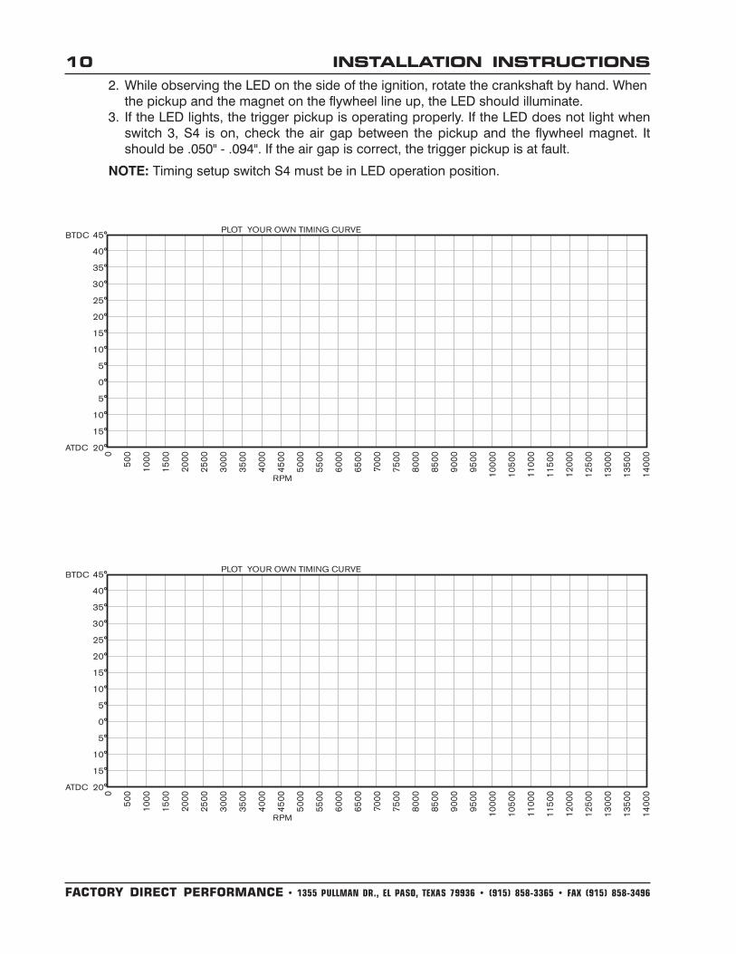
2. While observing the LED on the side of the ignition, rotate the crankshaft by hand. Whenthe pickup and the magnet on the flywheel line up, the LED should illuminate.
3. If the LED lights, the trigger pickup is operating properly. If the LED does not light whenswitch 3, S4 is on, check the air gap between the pickup and the flywheel magnet. Itshould be .050" - .094". If the air gap is correct, the trigger pickup is at fault.
NOTE: Timing setup switch S4 must be in LED operation position.

FACTORY DIRECT PERFORMANCE • 1355 PULLMAN DR., EL PASO, TEXAS 79936 • (915) 858-3365 • FAX (915) 858-3496
INSTALLATION INSTRUCTIONS 11
FACTORY DIRECT PERFORMANCE • 1355 PULLMAN DR., EL PASO, TEXAS 79936 • (915) 858-3365 • FAX (915) 858-3496
FRM21258 Revised 11/99 Printed In U.S.A.
TECH NOTES________________________________________________________________________________________________________________________________________________________________________________________________________________________________________________________________________________________________________________________________________________________________________________________________________________________________________________________________________________________________________________________________________________________________________________________________________________________________________________________________________________________________________________________________________________________________________________________________________________________________________________________________________________________________________________________________________________________________________________________________________________________________________________________________________________
Service
In case of malfunction, this component will be repaired free of charge according to the terms of thewarranty. When returning components for service, Proof of Purchase must be supplied for warrantyverification. After the warranty period has expired, repair service is charged based on a minimum andmaximum charge.
Send the unit prepaid with proof of purchase to the attention of: Customer Service Department,Factory Direct Performance, 1355 Pullman Dr., El Paso Texas 79936.
When returning the unit for repair, leave all wires at the length in which you have them installed. Besure to include a detailed account of any problems experienced, and what components and accessoriesare installed on the vehicle.
The repaired unit will be returned as soon as possible after receipt, COD/Cashiers Check for anycharges. For more information, call the FDP Customer Service Line (915) 858-3365. FDP techniciansare available from 8:00 a.m. to 5:00 p.m. Monday - Friday (Mountain Time).
Limited Warranty
Factory Direct Performance warrants this product to be free from defects in material and workmanshipunder its intended normal use* and if properly installed, for a period of one year from the date of originalpurchase. If found to be defective as mentioned above, it will be repaired or replaced at the option ofFactory Direct Performance. Any item that is covered under this warranty will be returned free of chargethrough standard shipping methods. If faster service is required the customer has the option of payingfor this service.
This shall constitute the sole remedy of the purchaser and the sole liability of Factory DirectPerformance. To the extent permitted by law, the foregoing is exclusive and in lieu of all other warrantiesor representations whether expressed or implied, including any implied warranty of merchantability orfitness. In no event shall Factory Direct Performance or its suppliers be liable for special or consequentialdamages.
*Intended normal use means that this item is being used as was originally intended and for theoriginal application as sold by Factory Direct Performance. Any modifications to this item or if it is usedon an application other than what Factory Direct Performance markets the product, the warranty will bevoid. It is the sole responsibility of the customer to determine that this item will work for the applicationthey are intending. Factory Direct Performance will accept no liability for custom applications.