multi 9xologic.com/vendors/ad/files/square_d_m9f11101_catalog.pdf3 c60bp circuit breakers ul 489...
TRANSCRIPT

CM909007E
Multi 9
Catalogue 2016
schneider-electric.com
This catalogue contains information about products under development, the characteristics may change without prior notice.

CM909007E
PanoramaMulti 9 components for machine circuits protection - IEC compliant
CM901002E 1
Multi standart circuit breakerC60BP - C60BPR UL489 CM901002E 3C60SP UL1077 CM901003E 8C60H-DC UL1077 CM901004E 11
C60N IEC 60947-2 CM901045E 14
C60H IEC 60947-2 CM901046E 16C60L IEC 60947-2 CM901047E 18
C60 CTRL CM901049E 20
N40N IEC 60947-2 CM901043E 22
Residual current devicesGFP - Ground Fault Protector UL 1053 CM902024E 25ID -Residual current circuit breaker CM902018E 27Vigi C60 - Residual current devices add-on CM902022E 29Vigi N40 - Residual current devices add-on CM902019E 31N40 Vigi - RCBO CM902020E 33
Accessories, auxiliariesElectrical auxiliaries CM907025E 35Accessories CM907026E 40Comb busbars for C60BP UL 489 circuit breakers CM907027E 44Comb busbars for C60BP UL 489 circuit breakers CM907011E 46
Comb busbars for C60SP UL 1077 circuit breakers CM907030E 47Linergy DS Screw distribution blocks CA907023E 56
Complemantary technical informationTripping curves CM908009E 59
ContentsMulti9 Multi9
1
Protection
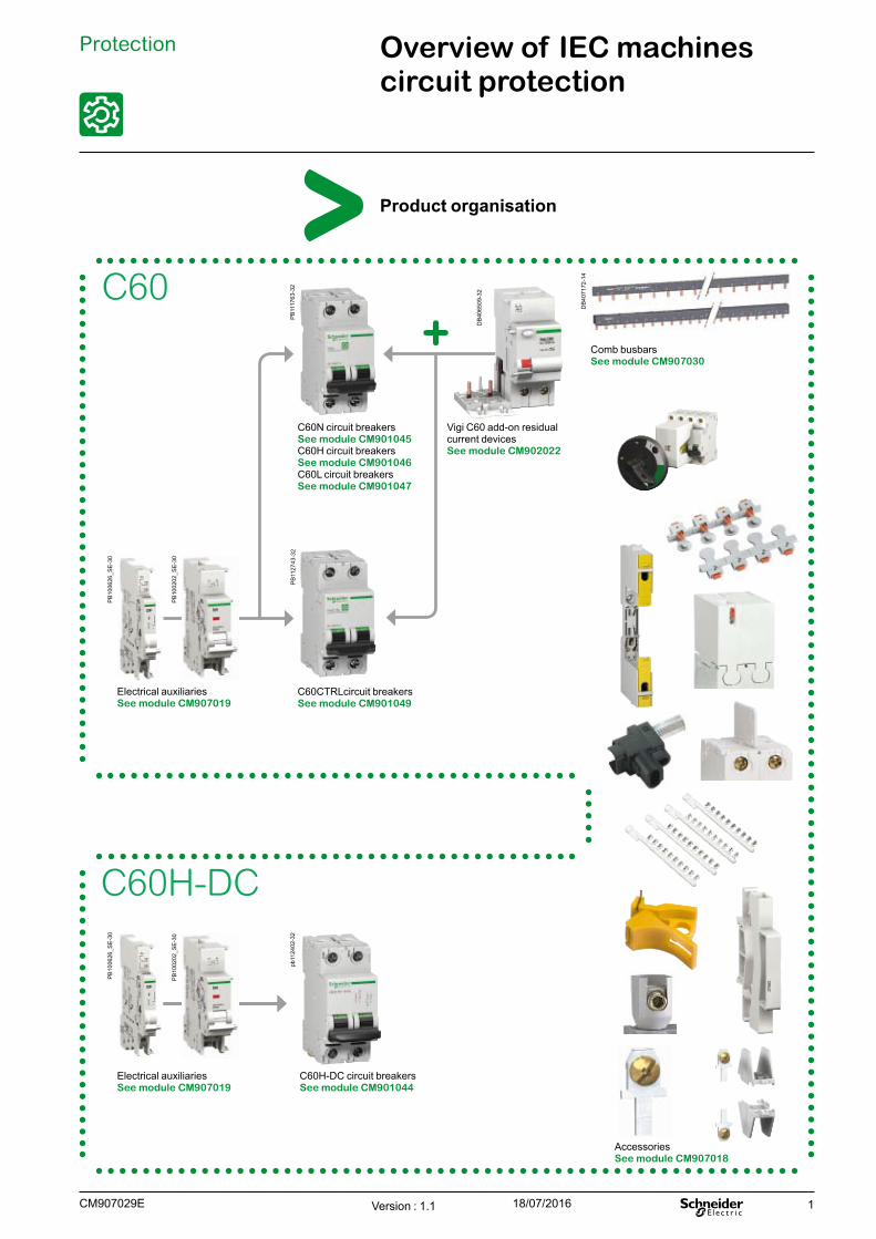
Product organisation
Overview of IEC machines circuit protection
Electrical auxiliaries See module CM907019
Electrical auxiliaries See module CM907019
C60H-DC
C60H-DC circuit breakers See module CM901044
C60N circuit breakers See module CM901045C60H circuit breakers See module CM901046C60L circuit breakers See module CM901047
C60CTRLcircuit breakers See module CM901049
C60
Accessories See module CM907018
Comb busbars See module CM907030
Vigi C60 add-on residual current devices See module CM902022
Version : 1.1 18/07/2016CM907029E
PB
1006
26_S
E-3
0P
B10
0626
_SE
-30
pb11
2402
-32
PB
1117
63-3
2P
B11
2743
-32
DB
4065
09-3
2
PB
1002
02_S
E-3
0P
B10
0202
_SE
-30
DB
4071
72-1
4

2
Protection Overview of IEC machines circuit protection (cont.)
N40N circuit breakers See module CM901043
Vigi N40 add-on residual current devices See module CM902019
ID residual current circuit breakers See module CM902018
N40 Vigi residual current devices See module CM902020
Electrical auxiliaries See module CM907018
Electrical auxiliaries See module CM907019
OF.S electrical auxiliary
Electrical auxiliaries See module CM907019
N40N
N40 Vigi
RCCB/ID
Accessories See module CM907018
Accessories See module CM907018
Accessories See module CM907018
Comb busbars See module CM907030
Comb busbars See module CM907030
Version : 1.1 18/07/2016 CM907029E
PB
1006
26_S
E-3
0P
B10
0626
_SE
-30
PB
1006
28_S
E-3
0
PB
1117
60-3
2
PB
1117
58-3
2
PB
1117
61-3
2
PB
1117
59-3
2
PB
1002
02_S
E-3
0
PB
1006
26_S
E-3
0
PB
1002
02_S
E-3
0P
B10
0202
_SE
-30
PB
5023
82-1
8P
B50
2382
-18

3
C60BP circuit breakers UL 489 branch circuit protection(Z, C and D curves)Tunnel terminal connection
ProtectionCircuit protection
UL 489 / CSA C22.2 No 5 / IEC/EN 60947-2 / GB 14048-2C60BP are multi-standard miniature circuit breakers and branch circuit protection as defined by UL 489. It combines following functions:
b circuit protection against short-circuit currents b circuit protection against overload currents b tripping and fault indication by the addition of auxiliaries.
Number of 18 mm (0.71 in.) poles
Rating (A) 25°C/77°F
Breaking capacity (kA rms)AIR IcuUL 489 / CSA C22.2 No 5 IEC 60947-2
Voltage (Ue) 277 V a 240 V a 120 V a 60 V c 440 V a 415 V a 240 V a 60 V c1P 0.5 to 35 10 14 14 10 - 3 10 20
40 to 63 - 10 10 10 - 3 10 20Voltage (Ue) 480Y/277 V a 240 V a 125 V c 440 V a 415 V a 240 V a 125 V c
2P 1 to 35 10 14 10 6 10 20 -3P 1 to 35 10 14 - 6 10 20 -2P/3P 40 to 63 - 10 - 6 10 20 -
Electrical diagrams1P 2P 3P
60 V c531
642
DB
1057
27
DB
1057
28
IEC DB
4052
27
Catalogue numbersTunnel terminal connectionType 1P 2P 3PAuxiliaries Remote indication and tripping, module CM907025
Curve Width in 9 mm modules
Curve Width in 9 mm modules
Curve Width in 9 mm modulesRating (In) Z C D (=K) C D (=K) C D (=K)
C60BP
0.5 M9F44170 M9F42170 M9F43170 2 - - 4 - - 61 M9F44101 M9F42101 M9F43101 M9F42201 M9F43201 M9F42301 M9F433012 M9F44102 M9F42102 M9F43102 M9F42202 M9F43202 M9F42302 M9F433023 M9F44103 M9F42103 M9F43103 M9F42203 M9F43203 M9F42303 M9F433034 M9F44104 M9F42104 M9F43104 M9F42204 M9F43204 M9F42304 M9F433045 M9F44105 M9F42105 M9F43105 M9F42205 M9F43205 M9F42305 M9F433056 M9F44106 M9F42106 M9F43106 M9F42206 M9F43206 M9F42306 M9F433068 M9F44108 M9F42108 M9F43108 M9F42208 M9F43208 M9F42308 M9F4330810 M9F44110 M9F42110 M9F43110 M9F42210 M9F43210 M9F42310 M9F4331015 M9F44115 M9F42115 M9F43115 M9F42215 M9F43215 M9F42315 M9F4331520 M9F44120 M9F42120 M9F43120 M9F42220 M9F43220 M9F42320 M9F4332025 M9F44125 M9F42125 M9F43125 M9F42225 M9F43225 M9F42325 M9F4332530 M9F44130 M9F42130 M9F43130 M9F42230 M9F43230 M9F42330 M9F4333035 M9F44135 M9F42135 M9F43135 M9F42235 M9F43235 M9F42335 M9F4333540 M9F44140 M9F42140 M9F43140 M9F42240 M9F43240 M9F42340 M9F4334045 M9F44145 M9F42145 M9F43145 M9F42245 M9F43245 M9F42345 M9F4334550 M9F44150 M9F42150 M9F43150 M9F42250 M9F43250 M9F42350 M9F4335063 M9F44163 M9F42163 M9F43163 M9F42263 M9F43263 M9F42363 M9F43363Accessories Module CM907026
Version : 1.5 18/07/2016CM901002E
DB
4086
11
DB
4086
09
DB
4086
10
PB
1166
64-4
0P
B11
6665
-40
4
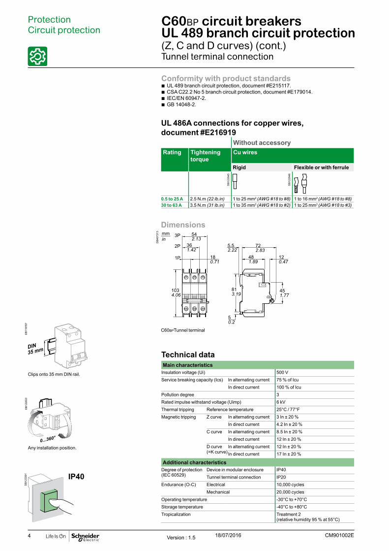
Dimensions
DB
4073
13
722.83
481.89
5.52.22
120.47
542.13
361.42
451.77
180.71
1P
2P
3P
1034.06
813.19
50.2
mmin
C60BPTunnel terminal
C60BP circuit breakers UL 489 branch circuit protection(Z, C and D curves) (cont.)Tunnel terminal connection
ProtectionCircuit protection
Conformity with product standards b UL 489 branch circuit protection, document #E215117. b CSA C22.2 No 5 branch circuit protection, document #E179014. b IEC/EN 60947-2. b GB 14048-2.
UL 486A connections for copper wires, document #E216919
Without accessoryRating Tightening
torqueCu wires
Rigid Flexible or with ferrule
0.5 to 25 A 2.5 N.m (22 lb.in) 1 to 25 mm2 (AWG #18 to #8) 1 to 16 mm2 (AWG #18 to #8)30 to 63 A 3.5 N.m (31 lb.in) 1 to 35 mm2 (AWG #18 to #2) 1 to 25 mm2 (AWG #18 to #3)
Technical dataMain characteristics
Insulation voltage (Ui) 500 VService breaking capacity (Ics) In alternating current 75 % of Icu
In direct current 100 % of IcuPollution degree 3Rated impulse withstand voltage (Uimp) 6 kVThermal tripping Reference temperature 25°C / 77°FMagnetic tripping Z curve In alternating current 3 In ± 20 %
In direct current 4.2 In ± 20 %C curve In alternating current 8.5 In ± 20 %
In direct current 12 In ± 20 %D curve (=K curve)
In alternating current 12 In ± 20 %In direct current 17 In ± 20 %
Additional characteristicsDegree of protection (IEC 60529)
Device in modular enclosure IP40Tunnel terminal connection IP20
Endurance (O-C) Electrical 10,000 cyclesMechanical 20,000 cycles
Operating temperature -30°C to +70°CStorage temperature -40°C to +80°CTropicalization Treatment 2
(relative humidity 95 % at 55°C)
IP40
Clips onto 35 mm DIN rail.
Any installation position.
Version : 1.5 18/07/2016 CM901002E
DB
1187
67D
B12
2831
DB
1233
91
DB
1229
45
DB
1229
46
5
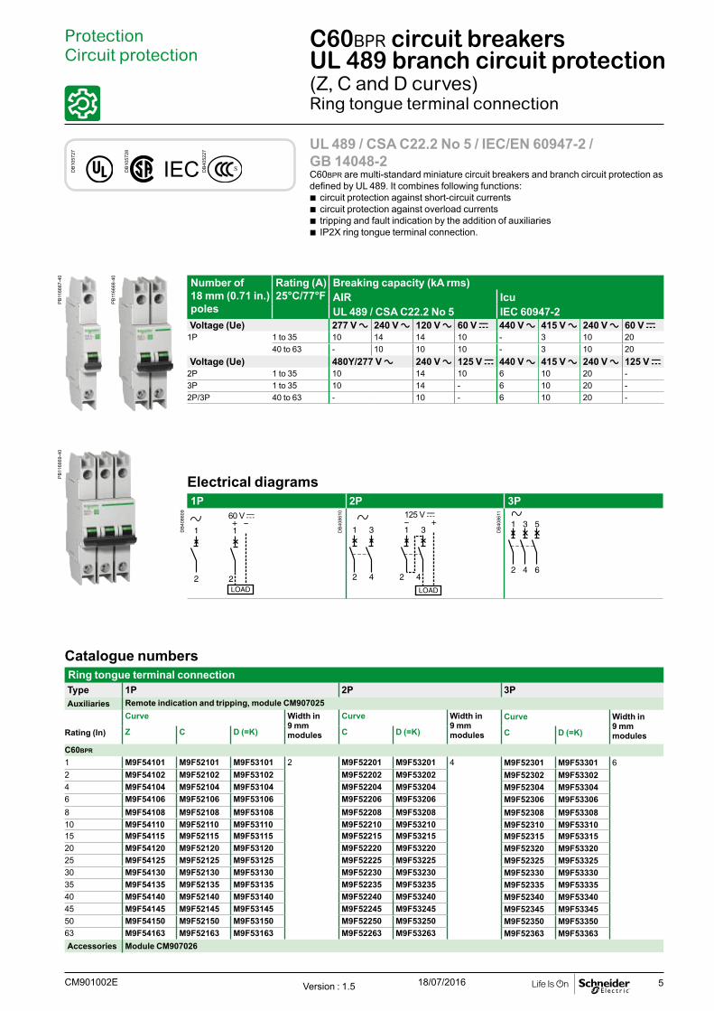
UL 489 / CSA C22.2 No 5 / IEC/EN 60947-2 / GB 14048-2C60BPR are multi-standard miniature circuit breakers and branch circuit protection as defined by UL 489. It combines following functions:
b circuit protection against short-circuit currents b circuit protection against overload currents b tripping and fault indication by the addition of auxiliaries b IP2X ring tongue terminal connection.
C60BPR circuit breakers UL 489 branch circuit protection(Z, C and D curves)Ring tongue terminal connection
ProtectionCircuit protection
DB
1057
27
DB
1057
28
IEC DB
4052
27
Catalogue numbersRing tongue terminal connectionType 1P 2P 3PAuxiliaries Remote indication and tripping, module CM907025
Curve Width in 9 mm modules
Curve Width in 9 mm modules
Curve Width in 9 mm modulesRating (In) Z C D (=K) C D (=K) C D (=K)
C60BPR
1 M9F54101 M9F52101 M9F53101 2 M9F52201 M9F53201 4 M9F52301 M9F53301 62 M9F54102 M9F52102 M9F53102 M9F52202 M9F53202 M9F52302 M9F533024 M9F54104 M9F52104 M9F53104 M9F52204 M9F53204 M9F52304 M9F533046 M9F54106 M9F52106 M9F53106 M9F52206 M9F53206 M9F52306 M9F533068 M9F54108 M9F52108 M9F53108 M9F52208 M9F53208 M9F52308 M9F5330810 M9F54110 M9F52110 M9F53110 M9F52210 M9F53210 M9F52310 M9F5331015 M9F54115 M9F52115 M9F53115 M9F52215 M9F53215 M9F52315 M9F5331520 M9F54120 M9F52120 M9F53120 M9F52220 M9F53220 M9F52320 M9F5332025 M9F54125 M9F52125 M9F53125 M9F52225 M9F53225 M9F52325 M9F5332530 M9F54130 M9F52130 M9F53130 M9F52230 M9F53230 M9F52330 M9F5333035 M9F54135 M9F52135 M9F53135 M9F52235 M9F53235 M9F52335 M9F5333540 M9F54140 M9F52140 M9F53140 M9F52240 M9F53240 M9F52340 M9F5334045 M9F54145 M9F52145 M9F53145 M9F52245 M9F53245 M9F52345 M9F5334550 M9F54150 M9F52150 M9F53150 M9F52250 M9F53250 M9F52350 M9F5335063 M9F54163 M9F52163 M9F53163 M9F52263 M9F53263 M9F52363 M9F53363Accessories Module CM907026
Number of 18 mm (0.71 in.) poles
Rating (A) 25°C/77°F
Breaking capacity (kA rms)AIR IcuUL 489 / CSA C22.2 No 5 IEC 60947-2
Voltage (Ue) 277 V a 240 V a 120 V a 60 V c 440 V a 415 V a 240 V a 60 V c1P 1 to 35 10 14 14 10 - 3 10 20
40 to 63 - 10 10 10 - 3 10 20Voltage (Ue) 480Y/277 V a 240 V a 125 V c 440 V a 415 V a 240 V a 125 V c
2P 1 to 35 10 14 10 6 10 20 -3P 1 to 35 10 14 - 6 10 20 -2P/3P 40 to 63 - 10 - 6 10 20 -
Electrical diagrams1P 2P 3P
60 V c531
642
Version : 1.5 18/07/2016CM901002E
PB
1166
67-4
0
DB
4086
11
DB
4086
09
DB
4086
10
PB
1166
68-4
0
PB
1166
69-4
0

6
Conformity with product standards b UL 489 branch circuit protection, document #E215117. b CSA C22.2 No 5 branch circuit protection, document #E179014. b IEC/EN 60947-2. b GB 14048-2.
C60BPR circuit breakers UL 489 branch circuit protection(Z, C and D curves) (cont.)Ring tongue terminal connection
ProtectionCircuit protection
UL 486A connections for copper wires, document #E216919
With accessoryRating Tightening torque Screw-on connection for ring
terminal
Ø A Ø 5.5 mm (0.22 in) min.
12 mm (0.47 in) max.
Thickness: 3 mm (0.12 in) or 2 x 1.5 mm (0.06 in) max.
1 to 63 A 2 N.m (18 lb.in) Ø A: 5 mm (#10)
Dimensions
DB
4073
14
1275.00
722.83
481.89
5.52.22
120.47
451.77
813.19
50.2
542.13
361.42
180.71
1P
2P
3Pmmin
C60BPR Ring tongue terminal
Technical dataMain characteristics
Insulation voltage (Ui) 500 VService breaking capacity (Ics) In alternating current 75 % of Icu
In direct current 100 % of IcuPollution degree 3Rated impulse withstand voltage (Uimp) 6 kVThermal tripping Reference temperature 25°C / 77°FMagnetic tripping Z curve In alternating current 3 In ± 20 %
In direct current 4.2 In ± 20 %C curve In alternating current 8.5 In ± 20 %
In direct current 12 In ± 20 %D curve (=K curve)
In alternating current 12 In ± 20 %In direct current 17 In ± 20 %
Additional characteristicsDegree of protection (IEC 60529)
Device in modular enclosure IP40Ring terminal connection IP20
Endurance (O-C) Electrical 10,000 cyclesMechanical 20,000 cycles
Operating temperature -30°C to +70°CStorage temperature -40°C to +80°CTropicalization Treatment 2
(relative humidity 95 % at 55°C)
IP40
Clips onto 35 mm DIN rail.
Any installation position.
Version : 1.5 18/07/2016 CM901002E
DB
4072
63
DB
1187
67D
B12
2831
DB
1233
91

7Version : 1.4 18/07/2016CM901003E
8
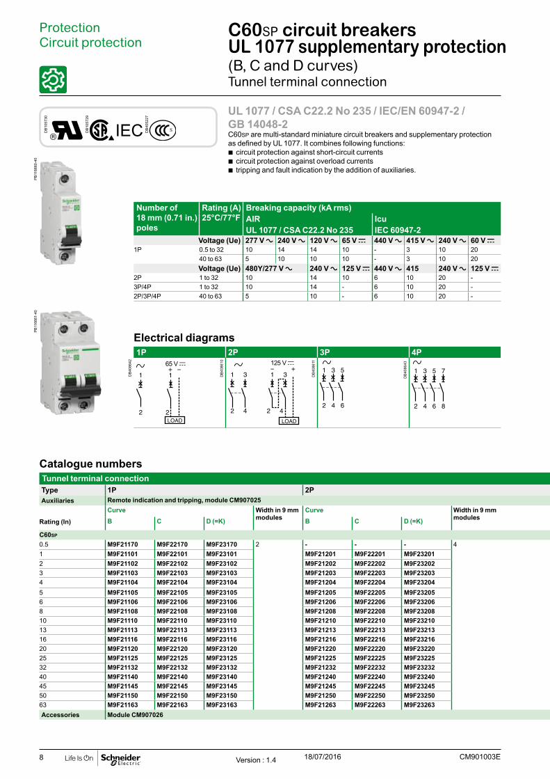
C60SP circuit breakers UL 1077 supplementary protection(B, C and D curves)Tunnel terminal connection
ProtectionCircuit protection
UL 1077 / CSA C22.2 No 235 / IEC/EN 60947-2 / GB 14048-2C60SP are multi-standard miniature circuit breakers and supplementary protection as defined by UL 1077. It combines following functions:
b circuit protection against short-circuit currents b circuit protection against overload currents b tripping and fault indication by the addition of auxiliaries.
Catalogue numbersTunnel terminal connectionType 1P 2P 3P 4PAuxiliaries Remote indication and tripping, module CM907025
Curve Width in 9 mm modules
Curve Width in 9 mm modules
Curve Width in 9 mm modules
Curve Width in 9 mm modulesRating (In) B C D (=K) B C D (=K) B C D (=K) B C D (=K)
C60SP
0.5 M9F21170 M9F22170 M9F23170 2 - - - 4 - - - 6 - - - 81 M9F21101 M9F22101 M9F23101 M9F21201 M9F22201 M9F23201 - - - - - -2 M9F21102 M9F22102 M9F23102 M9F21202 M9F22202 M9F23202 M9F21302 M9F22302 M9F23302 M9F21402 M9F22402 M9F234023 M9F21103 M9F22103 M9F23103 M9F21203 M9F22203 M9F23203 - - - - - -4 M9F21104 M9F22104 M9F23104 M9F21204 M9F22204 M9F23204 - - - - - -5 M9F21105 M9F22105 M9F23105 M9F21205 M9F22205 M9F23205 - - - - - -6 M9F21106 M9F22106 M9F23106 M9F21206 M9F22206 M9F23206 M9F21306 M9F22306 M9F23306 M9F21406 M9F22406 M9F234068 M9F21108 M9F22108 M9F23108 M9F21208 M9F22208 M9F23208 M9F21308 M9F22308 M9F23308 M9F21408 M9F22408 M9F2340810 M9F21110 M9F22110 M9F23110 M9F21210 M9F22210 M9F23210 M9F21310 M9F22310 M9F23310 M9F21410 M9F22410 M9F2341013 M9F21113 M9F22113 M9F23113 M9F21213 M9F22213 M9F23213 M9F21313 M9F22313 M9F23313 M9F21413 M9F22413 M9F2341316 M9F21116 M9F22116 M9F23116 M9F21216 M9F22216 M9F23216 M9F21316 M9F22316 M9F23316 M9F21416 M9F22416 M9F2341620 M9F21120 M9F22120 M9F23120 M9F21220 M9F22220 M9F23220 M9F21320 M9F22320 M9F23320 M9F21420 M9F22420 M9F2342025 M9F21125 M9F22125 M9F23125 M9F21225 M9F22225 M9F23225 M9F21325 M9F22325 M9F23325 M9F21425 M9F22425 M9F2342532 M9F21132 M9F22132 M9F23132 M9F21232 M9F22232 M9F23232 M9F21332 M9F22332 M9F23332 M9F21432 M9F22432 M9F2343240 M9F21140 M9F22140 M9F23140 M9F21240 M9F22240 M9F23240 M9F21340 M9F22340 M9F23340 M9F21440 M9F22440 M9F2344045 M9F21145 M9F22145 M9F23145 M9F21245 M9F22245 M9F23245 M9F21345 M9F22345 M9F23345 M9F21445 M9F22445 M9F2344550 M9F21150 M9F22150 M9F23150 M9F21250 M9F22250 M9F23250 M9F21350 M9F22350 M9F23350 M9F21450 M9F22450 M9F2345063 M9F21163 M9F22163 M9F23163 M9F21263 M9F22263 M9F23263 M9F21363 M9F22363 M9F23363 M9F21463 M9F22463 M9F23463Accessories Module CM907026
Number of 18 mm (0.71 in.) poles
Rating (A) 25°C/77°F
Breaking capacity (kA rms)AIR IcuUL 1077 / CSA C22.2 No 235 IEC 60947-2
Voltage (Ue) 277 V a 240 V a 120 V a 65 V c 440 V a 415 V a 240 V a 60 V c1P 0.5 to 32 10 14 14 10 - 3 10 20
40 to 63 5 10 10 10 - 3 10 20Voltage (Ue) 480Y/277 V a 240 V a 125 V c 440 V a 415 240 V a 125 V c
2P 1 to 32 10 14 10 6 10 20 -3P/4P 1 to 32 10 14 - 6 10 20 -2P/3P/4P 40 to 63 5 10 - 6 10 20 -
Electrical diagrams1P 2P 3P 4P
65 V c531
642
7531
8642
DB
1057
30
DB
1057
29
IEC DB
4052
27
Version : 1.4 18/07/2016 CM901003E
DB
4086
11
DB
4086
43
DB
4086
42
DB
4086
10
PB
1166
60-4
0P
B11
6661
-40

9
Catalogue numbersTunnel terminal connectionType 1P 2P 3P 4PAuxiliaries Remote indication and tripping, module CM907025
Curve Width in 9 mm modules
Curve Width in 9 mm modules
Curve Width in 9 mm modules
Curve Width in 9 mm modulesRating (In) B C D (=K) B C D (=K) B C D (=K) B C D (=K)
C60SP
0.5 M9F21170 M9F22170 M9F23170 2 - - - 4 - - - 6 - - - 81 M9F21101 M9F22101 M9F23101 M9F21201 M9F22201 M9F23201 - - - - - -2 M9F21102 M9F22102 M9F23102 M9F21202 M9F22202 M9F23202 M9F21302 M9F22302 M9F23302 M9F21402 M9F22402 M9F234023 M9F21103 M9F22103 M9F23103 M9F21203 M9F22203 M9F23203 - - - - - -4 M9F21104 M9F22104 M9F23104 M9F21204 M9F22204 M9F23204 - - - - - -5 M9F21105 M9F22105 M9F23105 M9F21205 M9F22205 M9F23205 - - - - - -6 M9F21106 M9F22106 M9F23106 M9F21206 M9F22206 M9F23206 M9F21306 M9F22306 M9F23306 M9F21406 M9F22406 M9F234068 M9F21108 M9F22108 M9F23108 M9F21208 M9F22208 M9F23208 M9F21308 M9F22308 M9F23308 M9F21408 M9F22408 M9F2340810 M9F21110 M9F22110 M9F23110 M9F21210 M9F22210 M9F23210 M9F21310 M9F22310 M9F23310 M9F21410 M9F22410 M9F2341013 M9F21113 M9F22113 M9F23113 M9F21213 M9F22213 M9F23213 M9F21313 M9F22313 M9F23313 M9F21413 M9F22413 M9F2341316 M9F21116 M9F22116 M9F23116 M9F21216 M9F22216 M9F23216 M9F21316 M9F22316 M9F23316 M9F21416 M9F22416 M9F2341620 M9F21120 M9F22120 M9F23120 M9F21220 M9F22220 M9F23220 M9F21320 M9F22320 M9F23320 M9F21420 M9F22420 M9F2342025 M9F21125 M9F22125 M9F23125 M9F21225 M9F22225 M9F23225 M9F21325 M9F22325 M9F23325 M9F21425 M9F22425 M9F2342532 M9F21132 M9F22132 M9F23132 M9F21232 M9F22232 M9F23232 M9F21332 M9F22332 M9F23332 M9F21432 M9F22432 M9F2343240 M9F21140 M9F22140 M9F23140 M9F21240 M9F22240 M9F23240 M9F21340 M9F22340 M9F23340 M9F21440 M9F22440 M9F2344045 M9F21145 M9F22145 M9F23145 M9F21245 M9F22245 M9F23245 M9F21345 M9F22345 M9F23345 M9F21445 M9F22445 M9F2344550 M9F21150 M9F22150 M9F23150 M9F21250 M9F22250 M9F23250 M9F21350 M9F22350 M9F23350 M9F21450 M9F22450 M9F2345063 M9F21163 M9F22163 M9F23163 M9F21263 M9F22263 M9F23263 M9F21363 M9F22363 M9F23363 M9F21463 M9F22463 M9F23463Accessories Module CM907026
C60SP circuit breakers UL 1077 supplementary protection(B, C and D curves) (cont.)Tunnel terminal connection
ProtectionCircuit protection
Conformity with product standards b UL 1077 supplementary protection , document #E90509. b CSA C22.2 No. 235 supplementary protection, document #E179014. b IEC/EN 60947-2. b GB 14048-2.
Dimensions
DB
4073
11 722.83
4P
722.83
441.73
5.52.22
160.63
451.77
813.19
50.2
542.13
361.42
180.71
1P
2P
3P
mmin
C60SP Tunnel terminal connection
UL 486A connections for copper wires, document #E216919
Without accessoryRating Tightening
torqueCu wires
Rigid Flexible or with ferrule
0.5 to 25 A 2.5 N.m (22 lb.in) 1 to 25 mm2 (AWG #18 to #8) 1 to 16 mm2 (AWG #18 to #8)30 to 63 A 3.5 N.m (31 lb.in) 1 to 35 mm2 (AWG #18 to #2) 1 to 25 mm2 (AWG #18 to #3)
Version : 1.4 18/07/2016CM901003E
DB
1229
45
DB
1229
46
10
C60SP circuit breakers UL 1077 supplementary protection(B, C and D curves) (cont.)
ProtectionCircuit protection
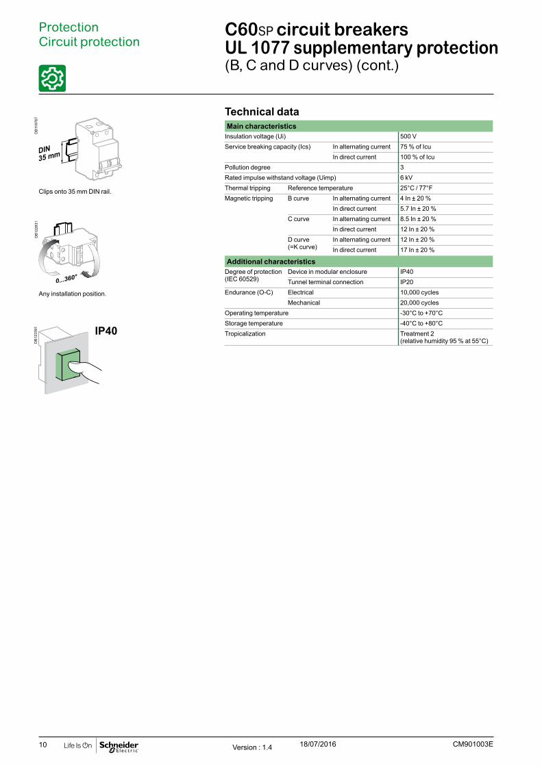
IP40
Clips onto 35 mm DIN rail.
Any installation position.
Technical dataMain characteristics
Insulation voltage (Ui) 500 VService breaking capacity (Ics) In alternating current 75 % of Icu
In direct current 100 % of IcuPollution degree 3Rated impulse withstand voltage (Uimp) 6 kVThermal tripping Reference temperature 25°C / 77°FMagnetic tripping B curve In alternating current 4 In ± 20 %
In direct current 5.7 In ± 20 %C curve In alternating current 8.5 In ± 20 %
In direct current 12 In ± 20 %D curve (=K curve)
In alternating current 12 In ± 20 %In direct current 17 In ± 20 %
Additional characteristicsDegree of protection (IEC 60529)
Device in modular enclosure IP40Tunnel terminal connection IP20
Endurance (O-C) Electrical 10,000 cyclesMechanical 20,000 cycles
Operating temperature -30°C to +70°CStorage temperature -40°C to +80°CTropicalization Treatment 2
(relative humidity 95 % at 55°C)
Version : 1.4 18/07/2016 CM901003E
DB
1187
67D
B12
2831
DB
1233
91
11
ProtectionCircuit protection
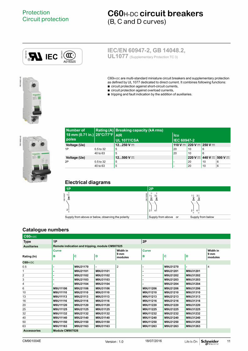
C60H-DC circuit breakers(B, C and D curves)
C60H-DC are multi-standard miniature circuit breakers and supplementary protectionas defined by UL 1077 dedicated to direct current. It combines following functions:
b circuit protection against short-circuit currents, b circuit protection against overload currents, b tripping and fault indication by the addition of auxiliaries.
IEC/EN 60947-2, GB 14048.2, UL1077 (Supplementary Protection TC 3)
Catalogue numbersC60H-DC
Type 1P 2PAuxiliaries Remote indication and tripping, module CM907025
Curve Width in 9 mm modules
Curve Width in 9 mm modulesRating (In) B C D B C D
C60H-DC
0.5 - M9U21170 - 2 - M9U21270 - 41 - M9U21101 M9U31101 - M9U21201 M9U312012 - M9U21102 M9U31102 - M9U21202 M9U312023 - M9U21103 M9U31103 - M9U21203 M9U312034 - M9U21104 M9U31104 - M9U21204 M9U312046 M9U11106 M9U21106 M9U31106 M9U11206 M9U21206 M9U3120610 M9U11110 M9U21110 M9U31110 M9U11210 M9U21210 M9U3131013 M9U11113 M9U21113 M9U31113 M9U11213 M9U21213 M9U3131316 M9U11116 M9U21116 M9U31116 M9U11216 M9U21216 M9U3131620 M9U11120 M9U21120 M9U31120 M9U11220 M9U21220 M9U3122025 M9U11125 M9U21125 M9U31125 M9U11225 M9U21225 M9U3122532 M9U11132 M9U21132 M9U31132 M9U11232 M9U21232 M9U3123240 M9U11140 M9U21140 M9U31140 M9U11240 M9U21240 M9U3124050 M9U11150 M9U21150 M9U31150 M9U11250 M9U21250 M9U3125063 M9U11163 M9U21163 M9U31163 M9U11263 M9U21263 M9U31263Accessories Module CM907026
Number of 18 mm (0.71 in.) poles
Rating (A) 25°C/77°F
Breaking capacity (kA rms)AIR IcuUL 1077/CSA IEC 60947-2
Voltage (Ue) 12...250 V c 110 V c 220 V c 250 V c1P 0.5 to 32 5 20 10 6
40 to 63 5 20 10 6Voltage (Ue) 12...500 V c 220 V c 440 V c 500 V c
2P 0.5 to 32 5 - 20 10 640 to 63 5 - 20 10 6
Electrical diagrams1P 2P
Supply from above or below, observing the polarity Supply from above or Supply from below
DB
1057
30
IEC DB
1234
31
Version : 1.0 18/07/2016CM901004E
DB
1165
87
DB
1165
88
PB
1166
81-4
0P
B11
6682
-40
12
ProtectionCircuit protection
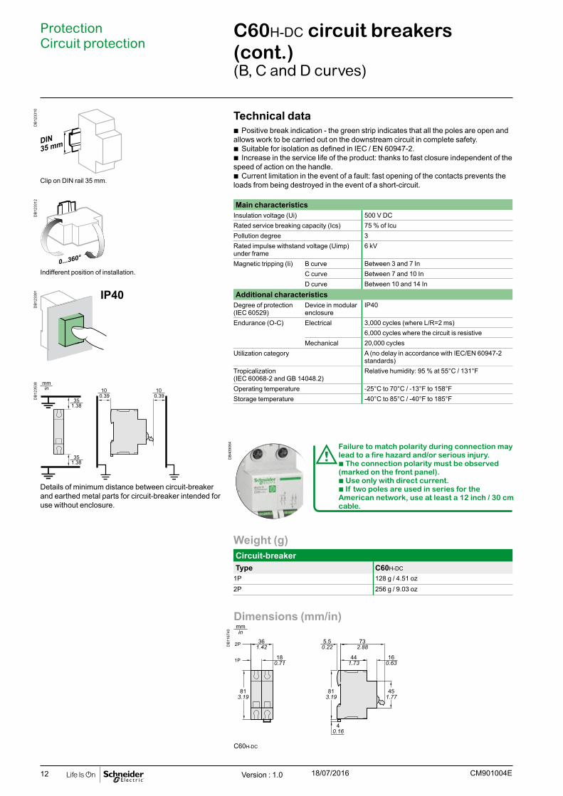
C60H-DC circuit breakers (cont.)(B, C and D curves)
Technical data b Positive break indication - the green strip indicates that all the poles are open and
allows work to be carried out on the downstream circuit in complete safety. b Suitable for isolation as defined in IEC / EN 60947-2. b Increase in the service life of the product: thanks to fast closure independent of the
speed of action on the handle. b Current limitation in the event of a fault: fast opening of the contacts prevents the
loads from being destroyed in the event of a short-circuit.
Main characteristicsInsulation voltage (Ui) 500 V DCRated service breaking capacity (Ics) 75 % of IcuPollution degree 3Rated impulse withstand voltage (Uimp) under frame
6 kV
Magnetic tripping (Ii) B curve Between 3 and 7 InC curve Between 7 and 10 InD curve Between 10 and 14 In
Additional characteristics Degree of protection (IEC 60529)
Device in modular enclosure
IP40
Endurance (O-C) Electrical 3,000 cycles (where L/R=2 ms)6,000 cycles where the circuit is resistive
Mechanical 20,000 cyclesUtilization category A (no delay in accordance with IEC/EN 60947-2
standards)Tropicalization (IEC 60068-2 and GB 14048.2)
Relative humidity: 95 % at 55°C / 131°F
Operating temperature -25°C to 70°C / -13°F to 158°FStorage temperature -40°C to 85°C / -40°F to 185°F
Weight (g)Circuit-breakerType C60H-DC
1P 128 g / 4.51 oz2P 256 g / 9.03 oz
IP40
Dimensions (mm/in)
DB
1167
40
C60H-DC
100.39
351.38
351.38
100.39
t
t
Clip on DIN rail 35 mm.
Indifferent position of installation.
Details of minimum distance between circuit-breaker and earthed metal parts for circuit-breaker intended for use without enclosure.
dFailure to match polarity during connection may lead to a fire hazard and/or serious injury.b The connection polarity must be observed (marked on the front panel). b Use only with direct current. b If two poles are used in series for the American network, use at least a 12 inch / 30 cm cable.
Version : 1.0 18/07/2016 CM901004E
DB
4090
64
DB
1233
10D
B12
3312
DB
1233
91D
B12
3538

13
ProtectionCircuit protection
C60H-DC circuit breakers (cont.)(B, C and D curves)
Multi-cables connection Without accessory
DB
1235
37
O-OFF
O-OFF
Rating Tightening torque
2 Copper cables 3 Multi-cables / Different wiresRigid / Stranded
Flexible or with ferrule
Flexible / Stranded
Flexible / Stranded / Rigid
y 25 A 2.5 N.m /22 lb.in
2 x 1 mm2 to 2 x 10 mm2
2 x 18 AWG - 2 x 8 AWG3 x 1 mm2
3 x 18 AWG2 x 2.5 mm2 + 1 x 1.5 mm2
2 x 13 AWG + 1 x 15 AWG> 25 A 3.5 N.m /
31 lb.in2 x 1 mm2 to 2 x 16 mm2
2 x 18 AWG - 2 x 6 AWG3 x 4 mm2
3 x 6 AWG2 x 10 mm2 + 1 x 6 mm2
2 x 8 AWG + 1 x 9 AWG
6.5 mm14 mm
PZ2
6.5 mm14 mm
PZ2
Connection Without accessory With accessories
DB
1235
37
O-OFF
O-OFF
Rating Tightening torque
Copper cables Screw-on connection for ring terminalRigid / Stranded Flexible or
with ferrule
y 25 A 2.5 N.m /22 lb.in
1 to 25 mm2
#18 - #4 AWG1 to 16 mm2
#18 - #6 AWGØ 5 mm (#12)
> 25 A 3.5 N.m /31 lb.in
1 to 35 mm2
#18 - #2 AWG1 to 25 mm2
#18 - #4 AWG
Version : 1.0 18/07/2016CM901004E
DB
1229
45
DB
1229
46
DB
1187
89
DB
1229
45
DB
1229
46
DB
1187
87

14 CM901045E
C60N circuit breakers (curve B, C, D)
Catalogue numbersC60N circuit breaker Type 1P 2P 3P 4P
Auxiliaries Modules CM907019 and CM907020Vigi C60 Module CM902022
Rating (In) Curve Curve Curve CurveB C D B C D B C D B C D
1 A M9F10101 M9F11101 M9F12101 M9F10201 M9F11201 M9F12201 M9F10301 M9F11301 M9F12301 M9F10401 M9F11401 M9F124012 A M9F10102 M9F11102 M9F12102 M9F10202 M9F11202 M9F12202 M9F10302 M9F11302 M9F12302 M9F10402 M9F11402 M9F124023 A M9F10103 M9F11103 M9F12103 M9F10203 M9F11203 M9F12203 M9F10303 M9F11303 M9F12303 M9F10403 M9F11403 M9F124034 A M9F10104 M9F11104 M9F12104 M9F10204 M9F11204 M9F12204 M9F10304 M9F11304 M9F12304 M9F10404 M9F11404 M9F124046 A M9F10106 M9F11106 M9F12106 M9F10206 M9F11206 M9F12206 M9F10306 M9F11306 M9F12306 M9F10406 M9F11406 M9F1240610 A M9F10110 M9F11110 M9F12110 M9F10210 M9F11210 M9F12210 M9F10310 M9F11310 M9F12310 M9F10410 M9F11410 M9F1241013 A M9F10113 M9F11113 M9F12113 M9F10213 M9F11213 M9F12213 M9F10313 M9F11313 M9F12313 M9F10413 M9F11413 M9F1241316 A M9F10116 M9F11116 M9F12116 M9F10216 M9F11216 M9F12216 M9F10316 M9F11316 M9F12316 M9F10416 M9F11416 M9F1241620 A M9F10120 M9F11120 M9F12120 M9F10220 M9F11220 M9F12220 M9F10320 M9F11320 M9F12320 M9F10420 M9F11420 M9F1242025 A M9F10125 M9F11125 M9F12125 M9F10225 M9F11225 M9F12225 M9F10325 M9F11325 M9F12325 M9F10425 M9F11425 M9F1242532 A M9F10132 M9F11132 M9F12132 M9F10232 M9F11232 M9F12232 M9F10332 M9F11332 M9F12332 M9F10432 M9F11432 M9F1243240 A M9F10140 M9F11140 M9F12140 M9F10240 M9F11240 M9F12240 M9F10340 M9F11340 M9F12340 M9F10440 M9F11440 M9F1244050 A M9F10150 M9F11150 - M9F10250 M9F11250 - M9F10350 M9F11350 - M9F10450 M9F11450 -63 A M9F10163 M9F11163 - M9F10263 M9F11263 - M9F10363 M9F11363 - M9F10463 M9F11463 -Width in 9-mm modules
2 4 6 8
Accessories Modules CM907018 and CM907020
Protection Circuit protection
IEC/EN 60947-2
b C60N circuit breakers are circuit breakers which combine the following functions: v circuit protection against short-circuit currents, v circuit protection against overload currents, v breaking and industrial disconnection as per standards IEC/EN 60947-2. b The presence of the green strip guarantees physical opening of the contacts and
allows operations to be performed on the downstream circuit in complete safety.
b Increased product service life thanks: v overvoltage resistance, v high performance limitation, v to fast closing independent of the speed of actuation of the toggle. b Upstream or downstream connection.
Positive contact indication b Suitability for isolation in accordance with the IEC/EN 60947-2 standard.
Alternating current (AC) 50/60 HzUltimate breaking capacity (Icu) as per IEC/EN 60947-2 Service
breaking capacity (Ics)
Voltage (Ue)Ph/Ph (2P, 3P, 4P) 240 V 415 V - 440 VPh/N (1P) - 240 V 415 V -
Rating (In) 1 to 63 A 20 kA 10 kA 3 kA(*) 6 kA 75 % of IcuiIT 1.2 x 12 In
(*) Breaking capacity under 1 pole with IT isolated neutral system (case of double fault).
C60N 1P C60N 3P
C60N 2P C60N 4PDirect current (DC) Breaking capacity (Icu) according to IEC/EN 60947-2 Service
breaking capacity (Ics)
Voltage (Ue)Between +/- y 72 V y 125 V y 125 V y 250 V
Number of poles 1P 2P 3P 4PRating (In) 1 to 63 A 15 kA 20 kA 30 kA 40 kA 100 % of Icu
Version : 1.5 18/07/2016
PB
1117
46-4
0P
B11
1749
-40
PB
1117
51-4
0P
B11
1754
-40
E45
092
E45
094
E45
095
E45
097

15CM901045E
Dimensions (mm)
DB
4060
67
725.5
44 16
45
5
72
54
36
18
81
Weight (g)Circuit-breaker Type C60N
1P 1202P 2403P 3604P 480
Technical dataAccording to IEC/EN 60947-2
Insulation voltage (Ui) 500 V ACPollution degree 3Rated impulse withstand voltage (Uimp) 6 kVThermal tripping Rated operating temperature 50°C
According to ambiant temperature See module CA908007Magnetic tripping (Ii) B curve in alternative current 4 In ± 20 %
in direct current 5.7 In (± 20 %)C curve in alternative current 8.5 In ± 20 %
in direct current 12 In (± 20 %)D curve in alternative current 12 In ± 20 %
in direct current 17 In (± 20 %)According to current frequency 50/60 Hz
Utilization category A
Additional characteristicsDegree of protection Device in modular enclosure IP40Endurance (O-C) Electrical 10,000 cycles
Mechanical 20,000 cyclesService temperature -30°C to +70°CStorage temperature -40°C to +80°CDissipated power See module CA908009
Clip on DIN rail 35 mm.
Indifferent position of installation.
C60N circuit breakers (curve B, C, D) (cont.)
Protection Circuit protection
Connection Without accessory With accessories
DB
1230
60 Rating Tightening torque
Copper cables 50 mm² Al terminal
Screw-on connection for ring terminal
Multi-cables terminalRigid Flexible or
with ferruleRigid cables
Flexible cables
1 to 25 A 2 N.m 1 to 25 mm2 1 to 25 mm2 - Ø 5 mm - -32 to 63 A 3.5 N.m 1.5 to 35 mm2 1.5 to 35 mm2 50 mm2 3 x 16 mm2 3 x 10 mm2
6.5 mm14 mm
PZ2
Version : 1.5 18/07/2016
DB
1187
67D
B11
8772
DB
1229
45
DB
1229
46
DB
1229
35
DB
1187
89
DB
1187
87
16 CM901046E
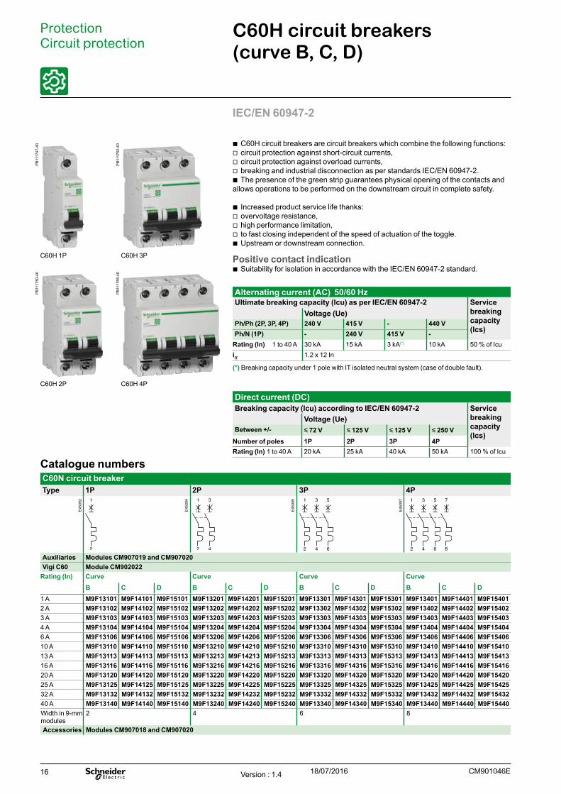
C60H circuit breakers (curve B, C, D)
Protection Circuit protection
IEC/EN 60947-2
b C60H circuit breakers are circuit breakers which combine the following functions: v circuit protection against short-circuit currents, v circuit protection against overload currents, v breaking and industrial disconnection as per standards IEC/EN 60947-2. b The presence of the green strip guarantees physical opening of the contacts and
allows operations to be performed on the downstream circuit in complete safety.
b Increased product service life thanks: v overvoltage resistance, v high performance limitation, v to fast closing independent of the speed of actuation of the toggle. b Upstream or downstream connection.
Positive contact indication b Suitability for isolation in accordance with the IEC/EN 60947-2 standard.
Alternating current (AC) 50/60 HzUltimate breaking capacity (Icu) as per IEC/EN 60947-2 Service
breaking capacity (Ics)
Voltage (Ue)Ph/Ph (2P, 3P, 4P) 240 V 415 V - 440 VPh/N (1P) - 240 V 415 V -
Rating (In) 1 to 40 A 30 kA 15 kA 3 kA(*) 10 kA 50 % of IcuiIT 1.2 x 12 In
(*) Breaking capacity under 1 pole with IT isolated neutral system (case of double fault).
C60H 1P C60H 3P
C60H 2P C60H 4P
Direct current (DC) Breaking capacity (Icu) according to IEC/EN 60947-2 Service
breaking capacity (Ics)
Voltage (Ue)Between +/- y 72 V y 125 V y 125 V y 250 V
Number of poles 1P 2P 3P 4PRating (In) 1 to 40 A 20 kA 25 kA 40 kA 50 kA 100 % of Icu
Catalogue numbersC60N circuit breaker Type 1P 2P 3P 4P
Auxiliaries Modules CM907019 and CM907020Vigi C60 Module CM902022
Rating (In) Curve Curve Curve CurveB C D B C D B C D B C D
1 A M9F13101 M9F14101 M9F15101 M9F13201 M9F14201 M9F15201 M9F13301 M9F14301 M9F15301 M9F13401 M9F14401 M9F154012 A M9F13102 M9F14102 M9F15102 M9F13202 M9F14202 M9F15202 M9F13302 M9F14302 M9F15302 M9F13402 M9F14402 M9F154023 A M9F13103 M9F14103 M9F15103 M9F13203 M9F14203 M9F15203 M9F13303 M9F14303 M9F15303 M9F13403 M9F14403 M9F154034 A M9F13104 M9F14104 M9F15104 M9F13204 M9F14204 M9F15204 M9F13304 M9F14304 M9F15304 M9F13404 M9F14404 M9F154046 A M9F13106 M9F14106 M9F15106 M9F13206 M9F14206 M9F15206 M9F13306 M9F14306 M9F15306 M9F13406 M9F14406 M9F1540610 A M9F13110 M9F14110 M9F15110 M9F13210 M9F14210 M9F15210 M9F13310 M9F14310 M9F15310 M9F13410 M9F14410 M9F1541013 A M9F13113 M9F14113 M9F15113 M9F13213 M9F14213 M9F15213 M9F13313 M9F14313 M9F15313 M9F13413 M9F14413 M9F1541316 A M9F13116 M9F14116 M9F15116 M9F13216 M9F14216 M9F15216 M9F13316 M9F14316 M9F15316 M9F13416 M9F14416 M9F1541620 A M9F13120 M9F14120 M9F15120 M9F13220 M9F14220 M9F15220 M9F13320 M9F14320 M9F15320 M9F13420 M9F14420 M9F1542025 A M9F13125 M9F14125 M9F15125 M9F13225 M9F14225 M9F15225 M9F13325 M9F14325 M9F15325 M9F13425 M9F14425 M9F1542532 A M9F13132 M9F14132 M9F15132 M9F13232 M9F14232 M9F15232 M9F13332 M9F14332 M9F15332 M9F13432 M9F14432 M9F1543240 A M9F13140 M9F14140 M9F15140 M9F13240 M9F14240 M9F15240 M9F13340 M9F14340 M9F15340 M9F13440 M9F14440 M9F15440Width in 9-mm modules
2 4 6 8
Accessories Modules CM907018 and CM907020
Version : 1.4 18/07/2016
PB
1117
47-4
0
PB
1117
52-4
0
PB
1117
50-4
0
PB
1117
55-4
0
E45
092
E45
094
E45
095
E45
097
17CM901046E
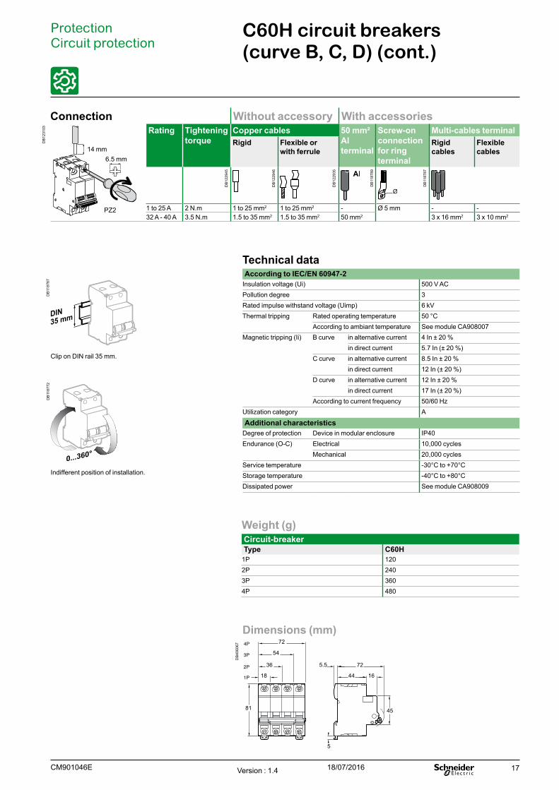
Weight (g)Circuit-breaker Type C60H
1P 1202P 2403P 3604P 480
Technical dataAccording to IEC/EN 60947-2
Insulation voltage (Ui) 500 V ACPollution degree 3Rated impulse withstand voltage (Uimp) 6 kVThermal tripping Rated operating temperature 50 °C
According to ambiant temperature See module CA908007Magnetic tripping (Ii) B curve in alternative current 4 In ± 20 %
in direct current 5.7 In (± 20 %)C curve in alternative current 8.5 In ± 20 %
in direct current 12 In (± 20 %)D curve in alternative current 12 In ± 20 %
in direct current 17 In (± 20 %)According to current frequency 50/60 Hz
Utilization category A
Additional characteristicsDegree of protection Device in modular enclosure IP40Endurance (O-C) Electrical 10,000 cycles
Mechanical 20,000 cyclesService temperature -30°C to +70°CStorage temperature -40°C to +80°CDissipated power See module CA908009
Clip on DIN rail 35 mm.
Indifferent position of installation.
C60H circuit breakers (curve B, C, D) (cont.)
Protection Circuit protection
Dimensions (mm)
DB
4060
67
725.5
44 16
45
5
72
54
36
18
81
Connection Without accessory With accessories
DB
1231
03 Rating Tightening torque
Copper cables 50 mm² Al terminal
Screw-on connection for ring terminal
Multi-cables terminalRigid Flexible or
with ferruleRigid cables
Flexible cables
1 to 25 A 2 N.m 1 to 25 mm2 1 to 25 mm2 - Ø 5 mm - -32 A - 40 A 3.5 N.m 1.5 to 35 mm2 1.5 to 35 mm2 50 mm2 3 x 16 mm2 3 x 10 mm2
6.5 mm14 mm
PZ2
Version : 1.4 18/07/2016
DB
1187
67D
B11
8772
DB
1229
45
DB
1229
46
DB
1229
35
DB
1187
89
DB
1187
87

18 Version : 1.2 18/07/2016 CM901047E
C60L circuit breakers (curve C)
Protection Circuit protection
IEC/EN 60947-2
b C60L circuit breakers are circuit breakers which combine the following functions: v circuit protection against short-circuit currents, v circuit protection against overload currents, v breaking and industrial disconnection as per standards IEC/EN 60947-2. b The presence of the green strip guarantees physical opening of the contacts and
allows operations to be performed on the downstream circuit in complete safety.
b Increased product service life thanks: v overvoltage resistance, v high performance limitation, v to fast closing independent of the speed of actuation of the toggle. b Upstream or downstream connection.
Positive contact indication b Suitability for isolation in accordance with the IEC/EN 60947-2 standard.
Alternating current (AC) 50/60 HzUltimate breaking capacity (Icu) as per IEC/EN 60947-2 Service
breaking capacity (Ics)
Voltage (Ue)Ph/Ph (2P, 3P, 4P) 240 V 415 V - 440 VPh/N (1P) - 240 V 415 V -
Rating (In) 1 to 25 A 50 kA 25 kA 3 kA(*) 20 kA 50 % of IcuiIT 1.2 x 8.5 In
(*) Breaking capacity under 1 pole with IT isolated neutral system (case of double fault).
C60L 1P C60L 3P
C60L 2P C60L 4P
Catalogue numbersC60L circuit breaker Type 1P 2P 3P 4P
Auxiliaries Modules CM907019 and CM907020Vigi C60 Module CM902022
Rating (In) Curve C Curve C Curve C Curve C1 A M9F17101 M9F17201 M9F17301 M9F174012 A M9F17102 M9F17202 M9F17302 M9F174023 A M9F17103 M9F17203 M9F17303 M9F174034 A M9F17104 M9F17204 M9F17304 M9F174046 A M9F17106 M9F17206 M9F17306 M9F1740610 A M9F17110 M9F17210 M9F17310 M9F1741016 A M9F17116 M9F17216 M9F17316 M9F1741620 A M9F17120 M9F17220 M9F17320 M9F1742025 A M9F17125 M9F17225 M9F17325 M9F17425Width in 9-mm modules 2 4 6 8Accessories Modules CM907018 and CM907020
Direct current (DC) Breaking capacity (Icu) according to IEC/EN 60947-2 Service
breaking capacity (Ics)
Voltage (Ue)Between +/- y 72 V y 125 V y 125 V y 250 V
Number of poles 1P 2P 3P 4PRating (In) 1 to 25 A 25 kA 30 kA 50 kA 60 kA 100 % of Icu
PB
1117
48-4
0
PB
1117
53-4
0
PB
1117
63-4
0
PB
1117
56-4
0
E45
092
E45
094
E45
095
E45
097

19Version : 1.2 18/07/2016CM901047E
Weight (g)Circuit-breaker Type C60L
1P 1202P 2403P 3604P 480
Technical dataAccording to IEC/EN 60947-2
Insulation voltage (Ui) 500 V ACPollution degree 3Rated impulse withstand voltage (Uimp) 6 kVThermal tripping Rated operating temperature 50°C
According to ambiant temperature See module CA908007Magnetic tripping (Ii) C curve in alternative current 8.5 In ± 20 %
in direct current 12 In (± 20 %)According to current frequency 50/60 Hz
Operating category A
Additional characteristicsDegree of protection Device in modular enclosure IP40Endurance (O-C) Electrical 10,000 cycles
Mechanical 20,000 cyclesService temperature -30°C to +70°CStorage temperature -40°C to +80°CDissipated power See module CA908009
Clip on DIN rail 35 mm.
Indifferent position of installation.
C60L circuit breakers (curve C) (cont.)
Protection Circuit protection
Dimensions (mm)
DB
4060
67
725.5
44 16
45
5
72
54
36
18
81
Connection Without accessory With accessory
DB
1231
03 Rating Tightening torque
Copper cables Screw-on connection for ring terminalRigid Flexible or
with ferrule
1 to 25 A 2 N.m 1 to 25 mm2 1 to 25 mm2 Ø 5 mm
6.5 mm14 mm
PZ2
DB
1187
67D
B11
8772
DB
1229
45
DB
1229
46
DB
1187
89

20 Version : 1.2 18/07/2016 CM901049E
C60CTRL circuit breakers for the protection of control circuits (C and Z curves)
ProtectionCircuit protection
IEC/EN 60947-2."C60CTRL circuit breakers for the protection of control circuits" protect and isolate:
b control circuits for industrial equipment with contactor coils, transformers, small motors, etc.
b programmable controllers (PLCs), voltage presence indicators, measuring and monitoring instruments, etc.
b single-phase auxiliary circuits such as solenoid valves, battery chargers, etc.
b C60CTRL circuit breakers combine the following features: v protection of circuits against short-circuit and overload currents, v breaking and isolation capability in the industrial sector to IEC/EN 60947-2.
b The presence of the green strip guarantees that the contacts open physically and allows work to be carried out safely on the downstream circuit.
b The service life of the products is improved by: v good overvoltage withstand capacity, v fast closure, independent of handle operating speed.
b They can be connected upstream and downstream.
Alternating current (AC) 50/60 HzBreaking capacity (Icu) to IEC/EN 60947-2 Service breaking
capacity (Ics)Voltage (Ue)Ph/Ph (2P) 240 V 415 VPh/N (1P) - 240 V
Rating (In) 1 to 4 A 100 kA 100 kA 50 % of Icu
C60CTRL 1P C60CTRL 2P
Catalogue numbersC60CTRL circuit breakers for the protection of control circuitsType 1P 2P
Auxiliaries Modules CM907019 and CM907020Vigi C60 Module CM902022
Rating (In) C curve Z curve C curve Z curve1 A M9C01101 M9C02301 M9C01201 M9C024012 A M9C01102 M9C02302 M9C01202 M9C024023 A M9C01103 M9C02303 M9C01203 M9C024034 A M9C01104 M9C02304 M9C01204 M9C02404Width in 9 mm modules 2 4Accessories Modules CM907018 and CM907020
Direct current (DC)Breaking capacity (Icu) to IEC/EN 60947-2 Service breaking
capacity (Ics)Voltage (Ue)Between +/- 60 V 125 V
Number of poles 1P 2PRating (In) 1 to 4 A 25 kA 30 kA 100 % of Icu
eCountry approval pictograms
E45
092
E45
094
PB
1127
42-4
0
PB
1127
43-4
0
21Version : 1.2 18/07/2016CM901049E
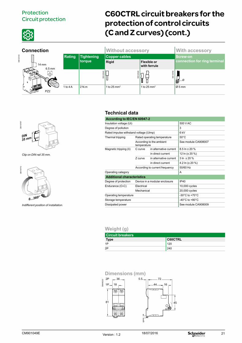
Weight (g)Circuit breakersType C60CTRL
1P 1202P 240
Technical dataAccording to IEC/EN 60947-2
Insulation voltage (Ui) 500 V ACDegree of pollution 3Rated impulse withstand voltage (Uimp) 6 kVThermal tripping Rated operating temperature 50°C
According to the ambient temperature
See module CA908007
Magnetic tripping (Ii) C curve in alternative current 8.5 In ± 20 %in direct current 12 In (± 20 %)
Z curve in alternative current 3 In ± 20 %in direct current 4.2 In (± 20 %)
According to current frequency 50/60 HzOperating category A
Additional characteristicsDegree of protection Device in a modular enclosure IP40Endurance (O-C) Electrical 10,000 cycles
Mechanical 20,000 cyclesOperating temperature -30°C to +70°CStorage temperature -40°C to +80°CDissipated power See module CA908009
Clip on DIN rail 35 mm.
Indifferent position of installation.
C60CTRL circuit breakers for the protection of control circuits (C and Z curves) (cont.)
ProtectionCircuit protection
Dimensions (mm)
DB
4062
22
725.5
44 16
45
5
362P
1P 18
81
Connection Without accessory With accessory
DB
1231
03 Rating Tightening torque
Copper cables Screw-on connection for ring terminalRigid Flexible or
with ferrule
1 to 4 A 2 N.m 1 to 25 mm2 1 to 25 mm2 Ø 5 mm
6.5 mm14 mm
PZ2
DB
1229
45
DB
1229
46
DB
1187
89
DB
1187
67D
B11
8772
22
ProtectionCircuit protection
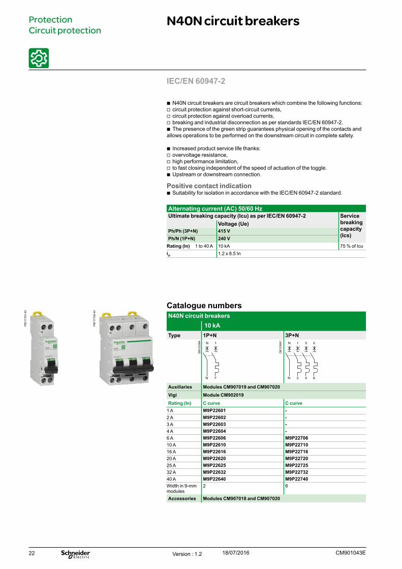
N40N circuit breakers
IEC/EN 60947-2
b N40N circuit breakers are circuit breakers which combine the following functions: v circuit protection against short-circuit currents, v circuit protection against overload currents, v breaking and industrial disconnection as per standards IEC/EN 60947-2. b The presence of the green strip guarantees physical opening of the contacts and
allows operations to be performed on the downstream circuit in complete safety.
b Increased product service life thanks: v overvoltage resistance, v high performance limitation, v to fast closing independent of the speed of actuation of the toggle. b Upstream or downstream connection.
Positive contact indication b Suitability for isolation in accordance with the IEC/EN 60947-2 standard.
Catalogue numbersN40N circuit breakers
10 kAType 1P+N 3P+N
Auxiliaries Modules CM907019 and CM907020Vigi Module CM902019Rating (In) C curve C curve
1 A M9P22601 -2 A M9P22602 -3 A M9P22603 -4 A M9P22604 -6 A M9P22606 M9P2270610 A M9P22610 M9P2271016 A M9P22616 M9P2271620 A M9P22620 M9P2272025 A M9P22625 M9P2272532 A M9P22632 M9P2273240 A M9P22640 M9P22740Width in 9-mm modules
2 6
Accessories Modules CM907018 and CM907020
Alternating current (AC) 50/60 HzUltimate breaking capacity (Icu) as per IEC/EN 60947-2 Service
breaking capacity (Ics)
Voltage (Ue)Ph/Ph (3P+N) 415 VPh/N (1P+N) 240 V
Rating (In) 1 to 40 A 10 kA 75 % of IcuiIT 1.2 x 8.5 In
Version : 1.2 18/07/2016 CM901043E
PB
1117
57-4
0
PB
1117
58-4
0
DB
1233
89
DB
1236
61

23
ProtectionCircuit protection
N40N circuit breakers (cont.)
Technical dataMain characteristicsAccording to IEC/EN 60947-2
Insulation voltage (Ui) Phase-to-phase 240...415 V ACThermal tripping Reference temperature 50 °C
Magnetic tripping C curve 8.5 In (± 20 %)
Limitation class 3Rated impulse withstand voltage (Uimp) 4 kVPollution degree 3Additional characteristics
Degree of protection (IEC 60529)
Device only IP20Device in modular enclosure IP40
Insulation class IIEndurance (O-C) Electrical y 20 A 20,000 cycles
u 25 A 10,000 cyclesMechanical 20,000 cycles
Operating temperature -25°C to +70°CStorage temperature -40°C to +70°CTropicalization (IEC 60068-1) Treatment 2
(relative humidity of 95 % at 55°C)
IP20 IP40
Clip on DIN rail 35 mm. Indifferent position of installation.
Dimensions (mm)
DB
4060
70
4.5
4.5
5.5
18543P+N
1P+N 44
78
4581
Weight (g)Circuit breakersType N40N
1P+N 1153P+N 322
Version : 1.2 18/07/2016CM901043E
DB
1233
14
DB
1233
10
DB
1233
12
24
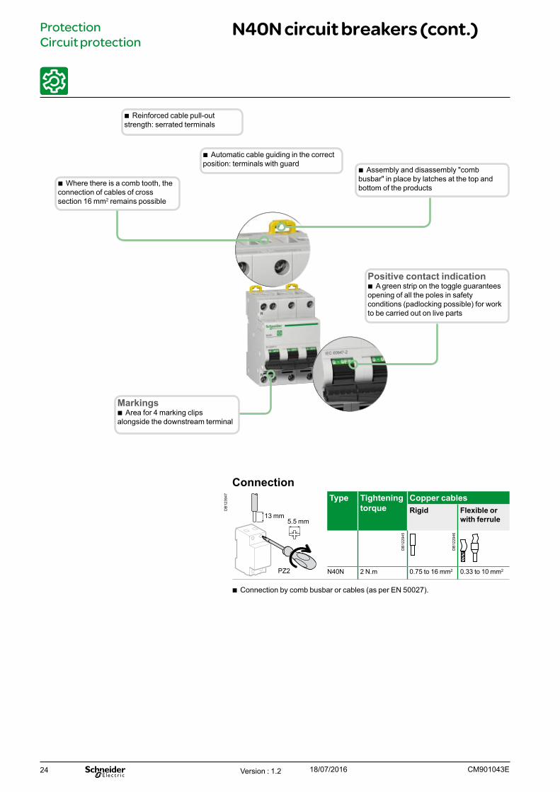
Connection
DB
1239
47 Type Tightening torque
Copper cablesRigid Flexible or
with ferrule
N40N 2 N.m 0.75 to 16 mm2 0.33 to 10 mm2
5.5 mm13 mm
PZ2
b Connection by comb busbar or cables (as per EN 50027).
b Where there is a comb tooth, the connection of cables of cross section 16 mm2 remains possible
Positive contact indication b A green strip on the toggle guarantees
opening of all the poles in safety conditions (padlocking possible) for work to be carried out on live parts
Markings b Area for 4 marking clips
alongside the downstream terminal
b Reinforced cable pull-out strength: serrated terminals
b Automatic cable guiding in the correct position: terminals with guard
ProtectionCircuit protection
N40N circuit breakers (cont.)
b Assembly and disassembly "comb busbar" in place by latches at the top and bottom of the products
Version : 1.2 18/07/2016 CM901043E
DB
1229
45
DB
1229
46

25
Protection Earth leakage protection
GFP - Ground Fault ProtectorUL 1053 IEC 61008
Catalogue numbersGFP UL 1053 type AC SI AC type SI
Rating (A)
Sensitivity (mA)
Cat. no. Width in mod. of 9 mm(0,354 in.)
UL 1053
IEC 61008 120 or 240 V230 or 240 V
240 V480Y/277 V230/400 or240/415 V
Auxiliaries Remote indication and tripping, module CM9070252P
25 26 30 60949 60969 486 100 60950 60971260 300 60951 -
40 26 30 60952 60972260 300 60954 -
63 26 30 60955 -
AC type SI
Rating (A)
Sensitivity (mA)
Cat. no. 240 V480Y/277 V230/400 or240/415 V
Width in mod. of 9 mm(0,354 in.)
UL 1053
IEC 61008
4P25 26 30 - 60989 8
86 100 - 60990260 300 - 60991
40 26 30 - 60992260 300 - 60994
63 26 30 - 6099586 100 - 60996
100 260 300 - 60999Accessories Module CM907026
UL 486A connections for copper wires, document #E216919Rating Tightening
torqueCu wires
DB
1229
45
25 to 100 A 3.5 N.m (31 lb.in) 1 to 35 mm2 (#18 #2 AWG)
IEC/EN 61008-1 UL 1053UL 1053 residual current circuit breakers already protected upstream by a short-circuit and overload protection device are used for:b control and disconnection of electric circuitsb protection of people against electric shock by direct and indirect contactsb protection of installations against insulation faultsb enhanced continuity of supply, during a series of close lightning strokes, IT earthing system, equipment including interference suppression filters, variable speed controllers, frequency converters, electronic ballasts for lightingb enhanced earth leakage protection: in presence of harmonics or high frequency rejections.
They comply with RCD standards UL 1053 and IEC 61008.
SI type GFPs are ideal for operation in environments with a humid atmosphere and/or polluted by aggressive agents: swimming pools, marinas, agri-food industries, water treatment stations, industrial sites, etc.
DB
1057
27
IEC DB
1057
28
DB
4052
27_1
Version : 1.1 18/07/2016CM902024E
PB
1016
14A
38_S
EP
B10
1615
A38
_SE
DB
1095
25D
B10
9526
26
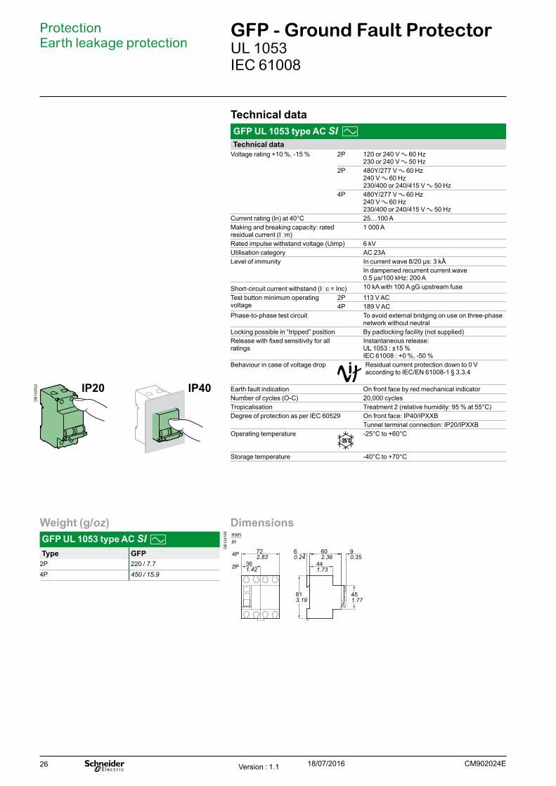
Technical dataGFP UL 1053 type AC SI Technical data
Voltage rating +10 %, -15 % 2P 120 or 240 V a 60 Hz230 or 240 V a 50 Hz
2P 480Y/277 V a 60 Hz240 V a 60 Hz230/400 or 240/415 V a 50 Hz
4P 480Y/277 V a 60 Hz240 V a 60 Hz230/400 or 240/415 V a 50 Hz
Current rating (ln) at 40°C 25…100 AMaking and breaking capacity: rated residual current (IDm)
1 000 A
Rated impulse withstand voltage (Uimp) 6 kVUtilisation category AC 23ALevel of immunity In current wave 8/20 µs: 3 kÂ
In dampened recurrent current wave 0.5 µs/100 kHz: 200 A
Short-circuit current withstand (IDc = Inc) 10 kA with 100 A gG upstream fuseTest button minimum operating voltage
2P 113 V AC4P 189 V AC
Phase-to-phase test circuit To avoid external bridging on use on three-phase network without neutral
Locking possible in “tripped” position By padlocking facility (not supplied)Release with fixed sensitivity for all ratings
Instantaneous release:UL 1053 : ±15 %IEC 61008 : +0 %, -50 %
Behaviour in case of voltage drop Residual current protection down to 0 V according to IEC/EN 61008-1 § 3.3.4
Earth fault indication On front face by red mechanical indicatorNumber of cycles (O-C) 20,000 cyclesTropicalisation Treatment 2 (relative humidity: 95 % at 55°C)Degree of protection as per IEC 60529 On front face: IP40/IPXXB
Tunnel terminal connection: IP20/IPXXBOperating temperature -25°C to +60°C
Storage temperature -40°C to +70°C
Protection Earth leakage protection
GFP - Ground Fault ProtectorUL 1053 IEC 61008
Weight (g/oz)GFP UL 1053 type AC SI Type GFP
2P 220 / 7.74P 450 / 15.9
IP20 IP40
Dimensions
DB
1241
09
2P
4P 722.83
451.77
813.19
60.24
90.35
602.36
441.73
361.42
mmin
Version : 1.1 18/07/2016 CM902024E
DB
1329
22
27
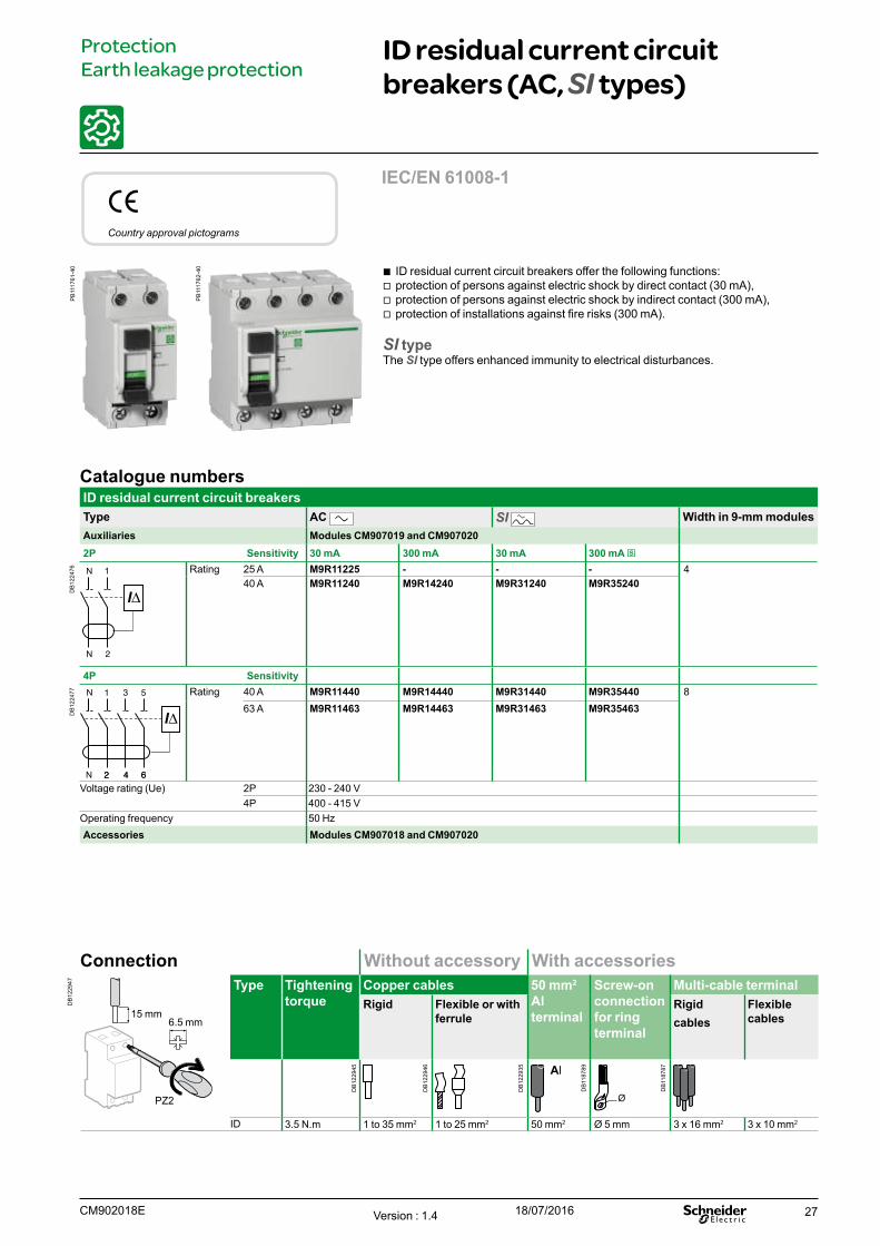
b ID residual current circuit breakers offer the following functions: v protection of persons against electric shock by direct contact (30 mA), v protection of persons against electric shock by indirect contact (300 mA), v protection of installations against fire risks (300 mA).
SI typeThe SI type offers enhanced immunity to electrical disturbances.
Catalogue numbersID residual current circuit breakersType AC SI Width in 9-mm modulesAuxiliaries Modules CM907019 and CM9070202P Sensitivity 30 mA 300 mA 30 mA 300 mA s
DB
1224
76 Rating 25 A M9R11225 - - - 440 A M9R11240 M9R14240 M9R31240 M9R35240
4P Sensitivity
DB
1224
77 Rating 40 A M9R11440 M9R14440 M9R31440 M9R35440 863 A M9R11463 M9R14463 M9R31463 M9R35463
Voltage rating (Ue) 2P 230 - 240 V4P 400 - 415 V
Operating frequency 50 HzAccessories Modules CM907018 and CM907020
eCountry approval pictograms
ID residual current circuit breakers (AC, SI types)
Protection Earth leakage protection
Connection Without accessory With accessories
DB
1229
47 Type Tightening torque
Copper cables 50 mm2 Al terminal
Screw-on connection for ring terminal
Multi-cable terminalRigid Flexible or with
ferruleRigidcables
Flexible cables
ID 3.5 N.m 1 to 35 mm2 1 to 25 mm2 50 mm2 Ø 5 mm 3 x 16 mm2 3 x 10 mm2
PZ2
15 mm6.5 mm
IEC/EN 61008-1
CM902018E Version : 1.4 18/07/2016
PB
1117
61-4
0
PB
1117
62-4
0
DB
1229
45
DB
1229
46
DB
1229
35
DB
1187
89
DB
1187
87
28
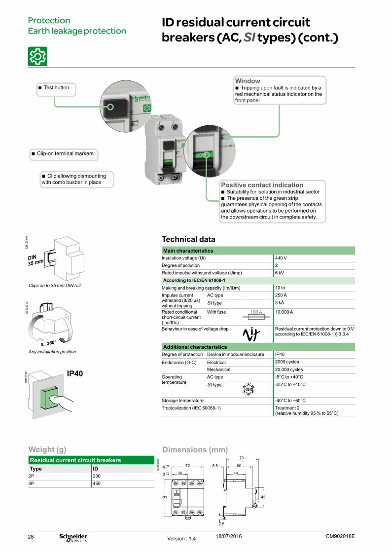
Technical dataMain characteristics
Insulation voltage (Ui) 440 VDegree of pollution 2Rated impulse withstand voltage (Uimp) 6 kVAccording to IEC/EN 61008-1
Making and breaking capacity (Im/IDm) 10 InImpulse current withstand (8/20 μs) without tripping
AC type 250 Â
SI type 3 kÂ
Rated conditional short-circuit current (Inc/IDc)
With fuse 10,000 A
Behaviour in case of voltage drop Residual current protection down to 0 V according to IEC/EN 61008-1 § 3.3.4
Additional characteristicsDegree of protection Device in modular enclosure IP40
Endurance (O-C) Electrical 2000 cycles
Mechanical 20,000 cyclesOperatingtemperature
AC type -5°C to +40°C
SI type -25°C to +40°C
Storage temperature -40°C to +60°C Tropicalization (IEC 60068-1) Treatment 2
(relative humidity 95 % to 55°C)
Clips on to 35 mm DIN rail.
Any installation position.
IP40
ID residual current circuit breakers (AC, SI types) (cont.)
Protection Earth leakage protection
Dimensions (mm)
DB
4060
69
2 P
4 P 5.5
73
45
60
44
72
36
81
7.5
Weight (g)Residual current circuit breakersType ID
2P 2304P 450
b Clip allowing dismounting with comb busbar in place Positive contact indication
b Suitability for isolation in industrial sector b The presence of the green strip
guarantees physical opening of the contacts and allows operations to be performed on the downstream circuit in complete safety.
b Clip-on terminal markers
b Test buttonWindow
b Tripping upon fault is indicated by a red mechanical status indicator on the front panel
CM902018EVersion : 1.4 18/07/2016
DB
1233
10D
B12
3312
DB
1233
91
29
ProtectionEarth leakage protection
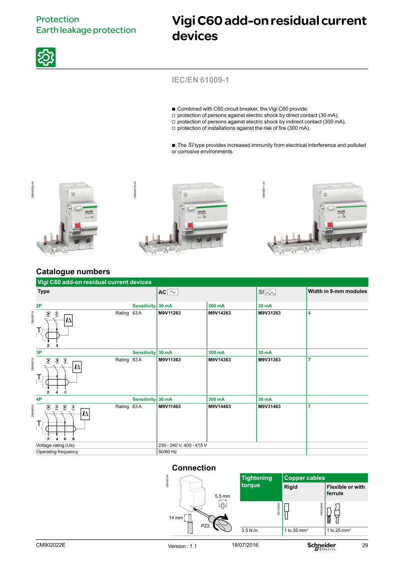
Vigi C60 add-on residual current devices
Catalogue numbersVigi C60 add-on residual current devicesType AC SI Width in 9-mm modules
2P Sensitivity 30 mA 300 mA 30 mA
DB
4065
18 Rating 63 A M9V11263 M9V14263 M9V31263 4
3P Sensitivity 30 mA 300 mA 30 mA
DB
4065
19 Rating 63 A M9V11363 M9V14363 M9V31363 7
4P Sensitivity 30 mA 300 mA 30 mA
DB
4065
20 Rating 63 A M9V11463 M9V14463 M9V31463 7
Voltage rating (Ue) 230 - 240 V, 400 - 415 VOperating frequency 50/60 Hz
Connection
DB
4061
59
Tightening torque
Copper cablesRigid Flexible or with
ferrule
3.5 N.m 1 to 35 mm2 1 to 25 mm2
5.5 mm
14 mm
PZ2
b Combined with C60 circuit breaker, the Vigi C60 provide: v protection of persons against electric shock by direct contact (30 mA), v protection of persons against electric shock by indirect contact (300 mA), v protection of installations against the risk of fire (300 mA).
b The SI type provides increased immunity from electrical interference and polluted or corrosive environments.
IEC/EN 61009-1
Version : 1.1 18/07/2016CM902022E
DB
4065
09-4
0
DB
4065
10-4
0
DB
4065
11-4
0
DB
1229
45
DB
1229
46
30
ProtectionEarth leakage protection
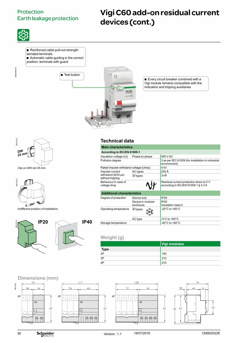
Vigi C60 add-on residual current devices (cont.)
Weight (g)Vigi modules
Type2P 1503P 2104P 210
b Every circuit breaker combined with a Vigi module remains compatible with the indication and tripping auxiliaries
IP20 IP40
Clip on DIN rail 35 mm.
Indifferent position of installation.
Technical dataMain characteristicsAccording to IEC/EN 61009-1
Insulation voltage (Ui) Phase-to-phase 500 V ACPollution degree 3 as per IEC 61009 (for installation in industrial
environment)Rated impulse withstand voltage (Uimp) 4 kVImpulse current withstand (8/20 μs) without tripping
AC types 250 ÂSI types 3 kÂ
Behaviour in case of voltage drop
Residual current protection down to 0 V according to IEC/EN 61009-1 § 3.3.8
Additional characteristicsDegree of protection Device only IP20
Device in modular enclosure
IP40 Insulation class II
Operating temperature SI types -25°C to +60°C
AC type -5°C to +60°CStorage temperature -40°C to +60°C
Dimensions (mm)
186-
0704
2P 3P 4P
b Reinforced cable pull-out strength: serrated terminals
b Automatic cable guiding in the correct position: terminals with guard
b Test button
Version : 1.1 18/07/2016 CM902022E
DB
4069
09-5
5D
B12
3310
DB
1233
12D
B12
3314
31
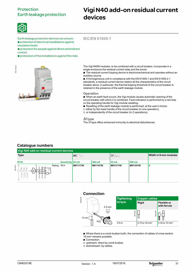
ProtectionEarth leakage protection
Vigi N40 add-on residual current devices
Earth leakage protection devices can ensure:b protection of electrical installations against insulation faultsb protection for people against direct and indirect contactb protection of the installations against fire risks.
Catalogue numbersVigi N40 add-on residual current devicesType AC SI Width in 9-mm modules
3P+N Sensitivity 30 mA 300 mA 30 mA 300 mA
DB
1236
71 NN
T
NN
Rating 40 A M9Y11740 M9Y14740 M9Y31740 M9Y34740 6
Connection
DB
4061
59
Tightening torque
Copper cablesRigid Flexible or
with ferrule
2 N.m 0.75 to 16 mm2 0.33 to 10 mm2
5.5 mm
13 mmPZ2
b Where there is a comb busbar tooth, the connection of cables of cross section 16 mm2 remains possible.
b Connection: v upstream: direct by comb busbar, v downstream: by cables.
The Vigi N40N modules, to be combined with a circuit breaker, incorporate in a single enclosure the residual current relay and the toroid.
b The residual current tripping device is electromechanical and operates without an auxiliary source.
b A homogeneous unit in compliance with the EN 61009-1 and EN 61009-2-1 standards, a residual current device retains all the characteristics of the circuit breaker alone; in particular, the thermal tripping threshold of the circuit breaker is retained in the presence of the earth leakage module.
Operation b When an earth fault occurs, the Vigi module causes automatic opening of the
circuit breaker with which it is combined. Fault indication is performed by a red strip on the operating handle for Vigi module resetting.
b Resetting of the earth leakage module is performed, at the user's choice: v either by the reset handle of the circuit breaker (in one operation), v or independently of the circuit breaker (in 2 operations).
SI typeThe SI type offers enhanced immunity to electrical disturbances.
IEC/EN 61009-1
Version : 1.4 18/07/2016CM902019E
PB
1117
60-4
0
DB
1229
45
DB
1229
46
32
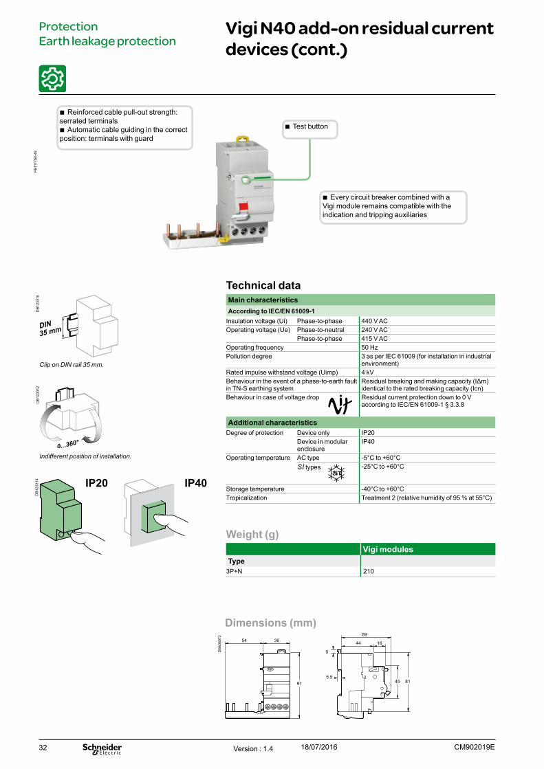
ProtectionEarth leakage protection
Vigi N40 add-on residual current devices (cont.)
Weight (g)Vigi modules
Type3P+N 210
b Every circuit breaker combined with a Vigi module remains compatible with the indication and tripping auxiliaries
IP20 IP40
Clip on DIN rail 35 mm.
Indifferent position of installation.
Technical dataMain characteristicsAccording to IEC/EN 61009-1
Insulation voltage (Ui) Phase-to-phase 440 V ACOperating voltage (Ue) Phase-to-neutral 240 V AC
Phase-to-phase 415 V ACOperating frequency 50 HzPollution degree 3 as per IEC 61009 (for installation in industrial
environment)Rated impulse withstand voltage (Uimp) 4 kVBehaviour in the event of a phase-to-earth fault in TN-S earthing system
Residual breaking and making capacity (IΔm) identical to the rated breaking capacity (Icn)
Behaviour in case of voltage drop Residual current protection down to 0 V according to IEC/EN 61009-1 § 3.3.8
Additional characteristicsDegree of protection Device only IP20
Device in modular enclosure
IP40
Operating temperature AC type -5°C to +60°CSI types -25°C to +60°C
Storage temperature -40°C to +60°CTropicalization Treatment 2 (relative humidity of 95 % at 55°C)
Dimensions (mm)
DB
4060
72
91
54 36
45 81
69
44 16
5
5.5
b Reinforced cable pull-out strength: serrated terminals
b Automatic cable guiding in the correct position: terminals with guard
b Test button
Version : 1.4 18/07/2016 CM902019E
PB
1117
60-4
5D
B12
3310
DB
1233
12D
B12
3314
33
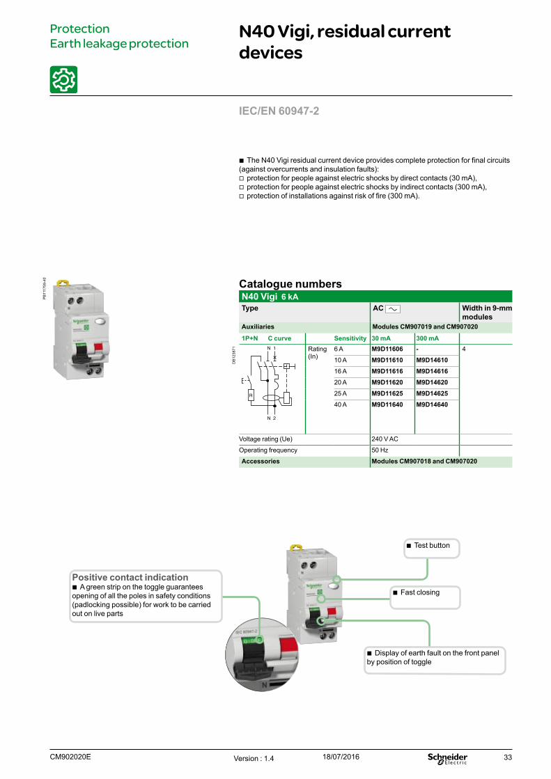
N40 Vigi, residual current devices
ProtectionEarth leakage protection
b The N40 Vigi residual current device provides complete protection for final circuits (against overcurrents and insulation faults):
v protection for people against electric shocks by direct contacts (30 mA), v protection for people against electric shocks by indirect contacts (300 mA), v protection of installations against risk of fire (300 mA).
Catalogue numbersN40 Vigi 6 kAType AC Width in 9-mm
modulesAuxiliaries Modules CM907019 and CM907020
1P+N C curve Sensitivity 30 mA 300 mA
DB
1238
71 Rating (In)
6 A M9D11606 - 4
10 A M9D11610 M9D1461016 A M9D11616 M9D1461620 A M9D11620 M9D1462025 A M9D11625 M9D1462540 A M9D11640 M9D14640
Voltage rating (Ue) 240 V AC
Operating frequency 50 Hz
Accessories Modules CM907018 and CM907020
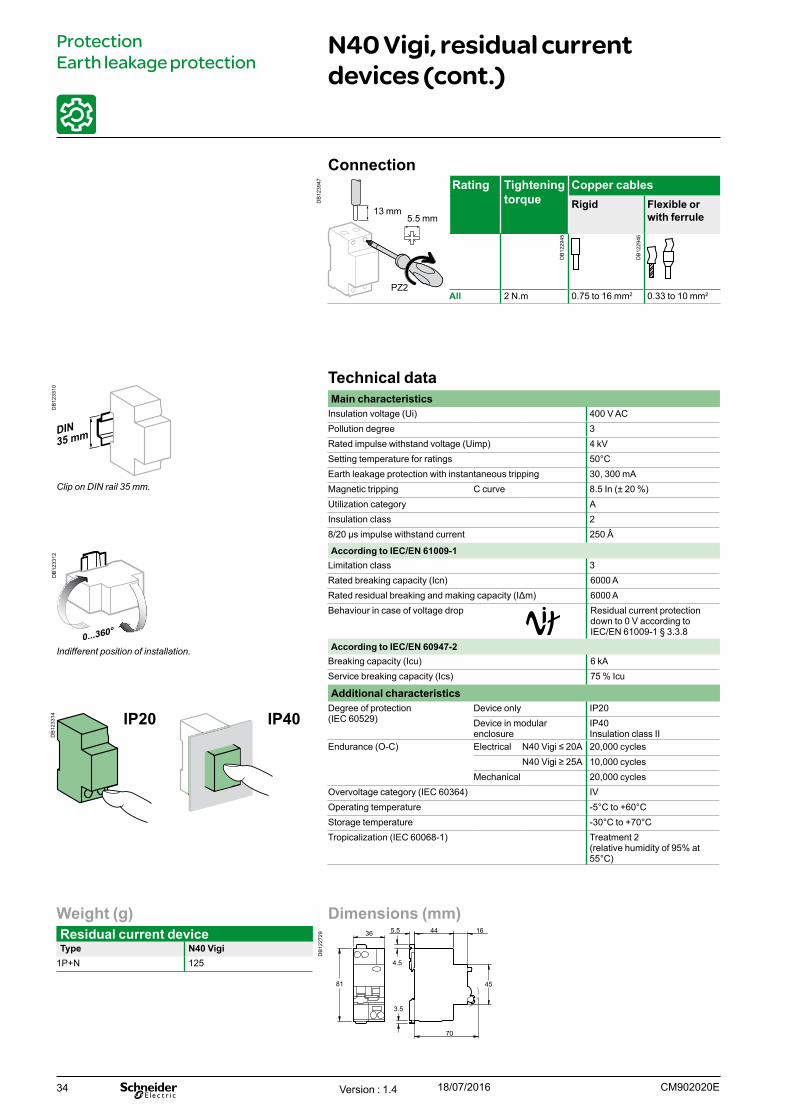
Positive contact indication b A green strip on the toggle guarantees
opening of all the poles in safety conditions (padlocking possible) for work to be carried out on live parts
b Fast closing
b Display of earth fault on the front panel by position of toggle
b Test button
IEC/EN 60947-2
Version : 1.4 18/07/2016CM902020E
PB
1117
59-4
0
34
Dimensions (mm)
DB
1227
29
36
81
3.5
4.5
445.5
70
45
16
Weight (g)Residual current deviceType N40 Vigi
1P+N 125
N40 Vigi, residual current devices (cont.)
ProtectionEarth leakage protection
IP20 IP40
Clip on DIN rail 35 mm.
Indifferent position of installation.
Technical dataMain characteristics
Insulation voltage (Ui) 400 V ACPollution degree 3Rated impulse withstand voltage (Uimp) 4 kVSetting temperature for ratings 50°CEarth leakage protection with instantaneous tripping 30, 300 mAMagnetic tripping C curve 8.5 In (± 20 %) Utilization category AInsulation class 28/20 µs impulse withstand current 250 Â
According to IEC/EN 61009-1Limitation class 3Rated breaking capacity (Icn) 6000 ARated residual breaking and making capacity (IΔm) 6000 ABehaviour in case of voltage drop Residual current protection
down to 0 V according to IEC/EN 61009-1 § 3.3.8
According to IEC/EN 60947-2Breaking capacity (Icu) 6 kAService breaking capacity (Ics) 75 % Icu
Additional characteristicsDegree of protection (IEC 60529)
Device only IP20Device in modular enclosure
IP40Insulation class II
Endurance (O-C) Electrical N40 Vigi ≤ 20A 20,000 cyclesN40 Vigi ≥ 25A 10,000 cycles
Mechanical 20,000 cyclesOvervoltage category (IEC 60364) IVOperating temperature -5°C to +60°CStorage temperature -30°C to +70°CTropicalization (IEC 60068-1) Treatment 2
(relative humidity of 95% at 55°C)
Connection
DB
1239
47 Rating Tightening torque
Copper cablesRigid Flexible or
with ferrule
All 2 N.m 0.75 to 16 mm2 0.33 to 10 mm2
5.5 mm13 mm
PZ2
Version : 1.4 18/07/2016 CM902020E
DB
1233
10D
B12
3312
DB
1233
14
DB
1229
45
DB
1229
46
35
Combination tableElectrical auxiliaries DevicesIndication Tripping Maximum number of indication auxiliaries (from left to right)
Maximum number of tripping auxiliaries
PB
1166
65-1
8
3 x OF or SD + 2 x MX or MNOr 2 x SD+OF or OF or SD 2 x MX or MN
C602 x OF + 2 x MX or MN
P10
0628
_SE
-10
PB
1166
70-1
8
1 x SD+OF 2 x MX or MN
OF.S + GFP UL 1053
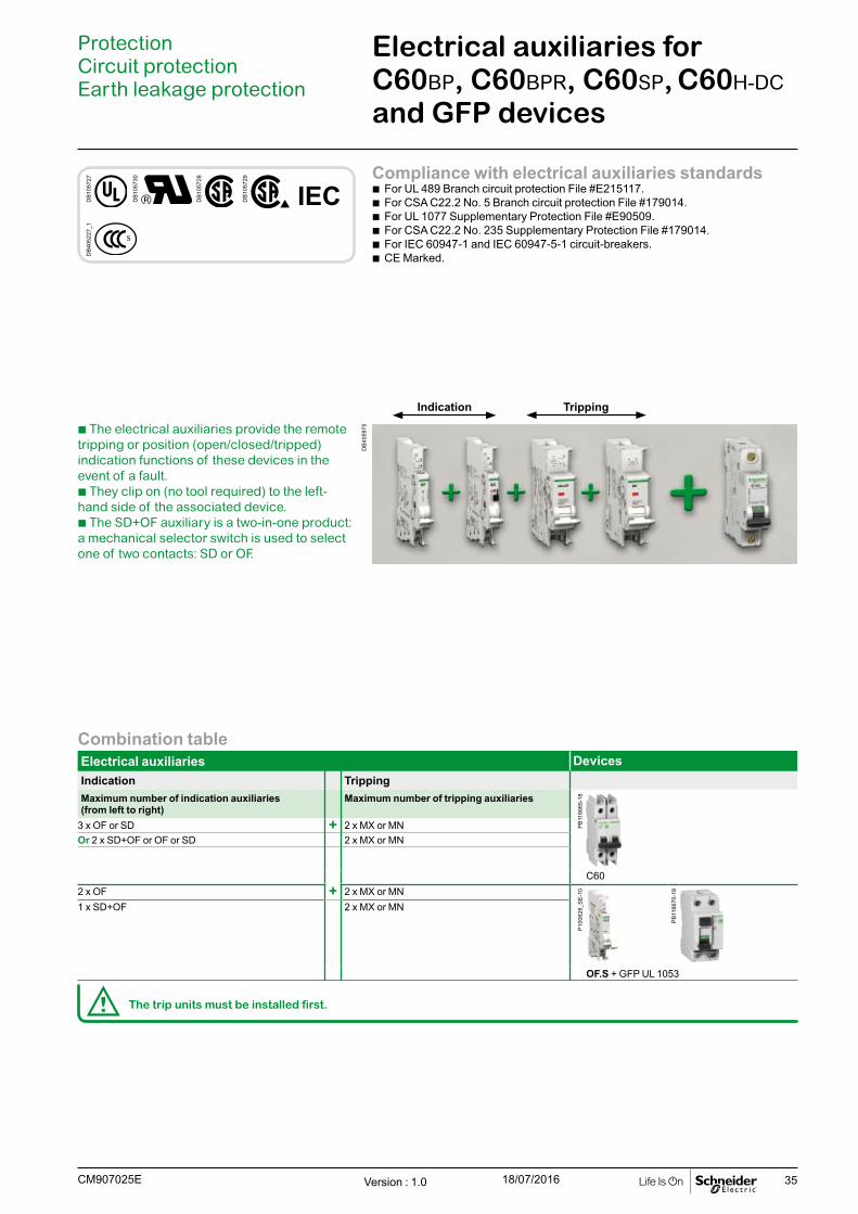
Electrical auxiliaries for C60BP, C60BPR, C60SP, C60H-DC and GFP devices
ProtectionCircuit protectionEarth leakage protection
b The electrical auxiliaries provide the remote tripping or position (open/closed/tripped) indication functions of these devices in the event of a fault.b They clip on (no tool required) to the left-hand side of the associated device.b The SD+OF auxiliary is a two-in-one product: a mechanical selector switch is used to select one of two contacts: SD or OF.
d The trip units must be installed first.
Compliance with electrical auxiliaries standards b For UL 489 Branch circuit protection File #E215117. b For CSA C22.2 No. 5 Branch circuit protection File #179014. b For UL 1077 Supplementary Protection File #E90509. b For CSA C22.2 No. 235 Supplementary Protection File #179014. b For IEC 60947-1 and IEC 60947-5-1 circuit-breakers. b CE Marked.
DB
4059
75
Indication Tripping
DB
1057
27
DB
1057
30
DB
1057
28
DB
1057
29
IEC
DB
4052
27_1
Version : 1.0 18/07/2016CM907025E
36
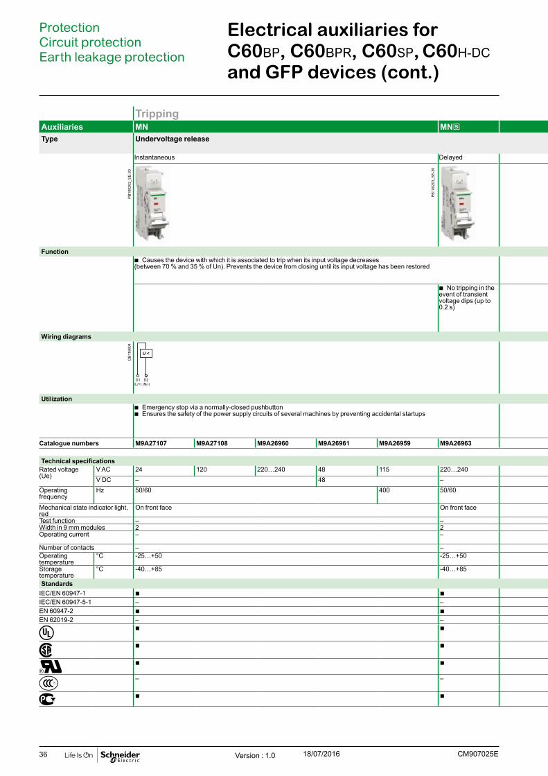
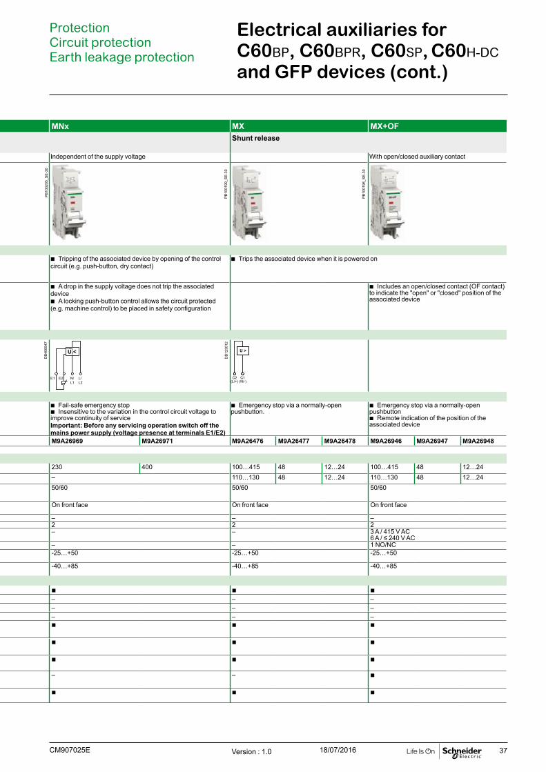
Tripping Auxiliaries MN MNs MNx MX MX+OFType Undervoltage release Shunt release
Instantaneous Delayed Independent of the supply voltage With open/closed auxiliary contact
Function b Causes the device with which it is associated to trip when its input voltage decreases
(between 70 % and 35 % of Un). Prevents the device from closing until its input voltage has been restored b Tripping of the associated device by opening of the control
circuit (e.g. push-button, dry contact) b Trips the associated device when it is powered on
b No tripping in the event of transient voltage dips (up to 0.2 s)
b A drop in the supply voltage does not trip the associated device
b A locking push-button control allows the circuit protected (e.g. machine control) to be placed in safety configuration
b Includes an open/closed contact (OF contact) to indicate the "open" or "closed" position of the associated device
Wiring diagrams
U <
E2 N/L1
L/L2
E1
U >
Utilization b Emergency stop via a normally-closed pushbutton b Ensures the safety of the power supply circuits of several machines by preventing accidental startups
b Fail-safe emergency stop b Insensitive to the variation in the control circuit voltage to
improve continuity of serviceImportant: Before any servicing operation switch off the mains power supply (voltage presence at terminals E1/E2)
b Emergency stop via a normally-open pushbutton.
b Emergency stop via a normally-open pushbutton
b Remote indication of the position of the associated device
Catalogue numbers M9A27107 M9A27108 M9A26960 M9A26961 M9A26959 M9A26963 M9A26969 M9A26971 M9A26476 M9A26477 M9A26478 M9A26946 M9A26947 M9A26948
Technical specificationsRated voltage (Ue)
V AC 24 120 220…240 48 115 220…240 230 400 100…415 48 12…24 100…415 48 12…24V DC – 48 – – 110…130 48 12…24 110…130 48 12…24
Operating frequency
Hz 50/60 400 50/60 50/60 50/60 50/60
Mechanical state indicator light, red
On front face On front face On front face On front face On front face
Test function – – – – –Width in 9 mm modules 2 2 2 2 2Operating current – – – – 3 A / 415 V AC
6 A / y 240 V ACNumber of contacts – – – – 1 NO/NCOperating temperature
°C -25…+50 -25…+50 -25…+50 -25…+50 -25…+50
Storage temperature
°C -40…+85 -40…+85 -40…+85 -40…+85 -40…+85
StandardsIEC/EN 60947-1 b b b b b IEC/EN 60947-5-1 – – – – –EN 60947-2 b b – – –EN 62019-2 – – – – –
b b b b b
b b b b b
b b b b b
– – – – b
b b b b b
Electrical auxiliaries for C60BP, C60BPR, C60SP, C60H-DC and GFP devices (cont.)
ProtectionCircuit protectionEarth leakage protection
Version : 1.0 18/07/2016 CM907025E
DB
1188
04P
B10
0202
_SE
-30
PB
1002
03_S
E-3
0
37
Tripping Auxiliaries MN MNs MNx MX MX+OFType Undervoltage release Shunt release
Instantaneous Delayed Independent of the supply voltage With open/closed auxiliary contact
Function b Causes the device with which it is associated to trip when its input voltage decreases
(between 70 % and 35 % of Un). Prevents the device from closing until its input voltage has been restored b Tripping of the associated device by opening of the control
circuit (e.g. push-button, dry contact) b Trips the associated device when it is powered on
b No tripping in the event of transient voltage dips (up to 0.2 s)
b A drop in the supply voltage does not trip the associated device
b A locking push-button control allows the circuit protected (e.g. machine control) to be placed in safety configuration
b Includes an open/closed contact (OF contact) to indicate the "open" or "closed" position of the associated device
Wiring diagrams
U <
E2 N/L1
L/L2
E1
U >
Utilization b Emergency stop via a normally-closed pushbutton b Ensures the safety of the power supply circuits of several machines by preventing accidental startups
b Fail-safe emergency stop b Insensitive to the variation in the control circuit voltage to
improve continuity of serviceImportant: Before any servicing operation switch off the mains power supply (voltage presence at terminals E1/E2)
b Emergency stop via a normally-open pushbutton.
b Emergency stop via a normally-open pushbutton
b Remote indication of the position of the associated device
Catalogue numbers M9A27107 M9A27108 M9A26960 M9A26961 M9A26959 M9A26963 M9A26969 M9A26971 M9A26476 M9A26477 M9A26478 M9A26946 M9A26947 M9A26948
Technical specificationsRated voltage (Ue)
V AC 24 120 220…240 48 115 220…240 230 400 100…415 48 12…24 100…415 48 12…24V DC – 48 – – 110…130 48 12…24 110…130 48 12…24
Operating frequency
Hz 50/60 400 50/60 50/60 50/60 50/60
Mechanical state indicator light, red
On front face On front face On front face On front face On front face
Test function – – – – –Width in 9 mm modules 2 2 2 2 2Operating current – – – – 3 A / 415 V AC
6 A / y 240 V ACNumber of contacts – – – – 1 NO/NCOperating temperature
°C -25…+50 -25…+50 -25…+50 -25…+50 -25…+50
Storage temperature
°C -40…+85 -40…+85 -40…+85 -40…+85 -40…+85
StandardsIEC/EN 60947-1 b b b b b IEC/EN 60947-5-1 – – – – –EN 60947-2 b b – – –EN 62019-2 – – – – –
b b b b b
b b b b b
b b b b b
– – – – b
b b b b b
Electrical auxiliaries for C60BP, C60BPR, C60SP, C60H-DC and GFP devices (cont.)
ProtectionCircuit protectionEarth leakage protection
Version : 1.0 18/07/2016CM907025E
DB
1230
12
DB
4069
47
PB
1001
99_S
E-3
0
PB
1001
98_S
E-3
0
PB
1002
05_S
E-3
0
38
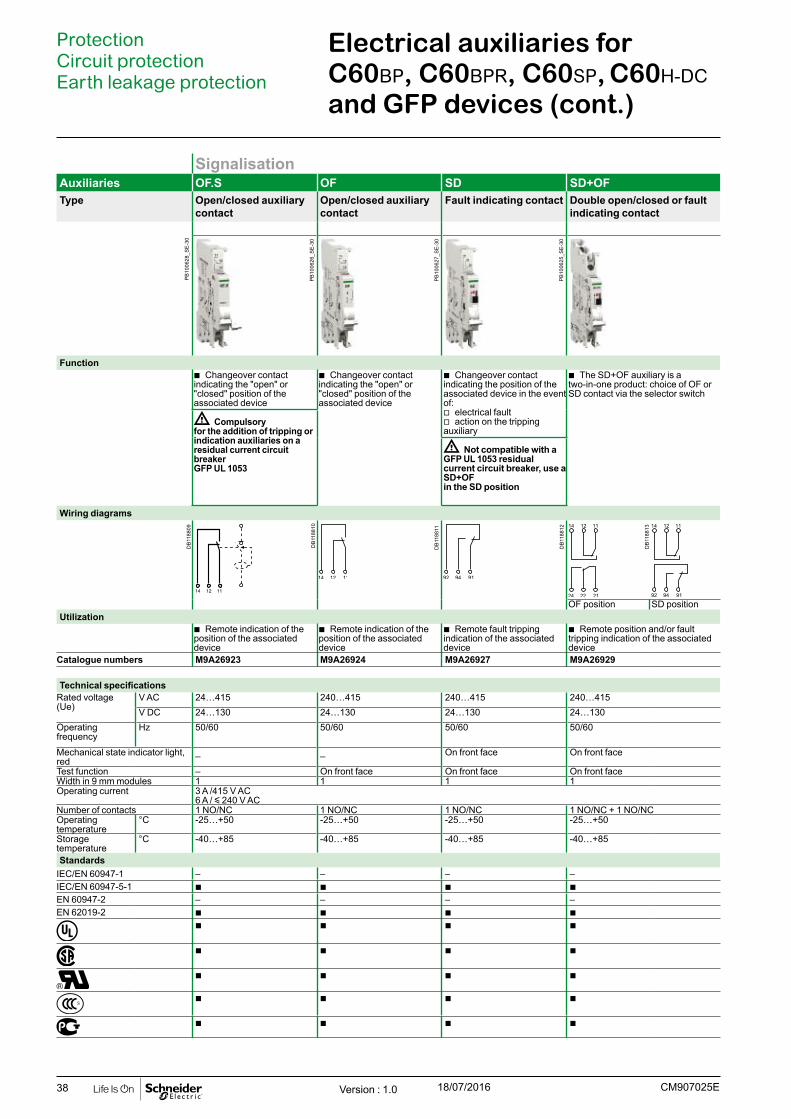
SignalisationAuxiliaries OF.S OF SD SD+OFType Open/closed auxiliary
contact Open/closed auxiliary contact
Fault indicating contact Double open/closed or fault indicating contact
Function b Changeover contact
indicating the "open" or "closed" position of the associated device
b Changeover contact indicating the "open" or "closed" position of the associated device
b Changeover contact indicating the position of the associated device in the event of:
v electrical fault v action on the tripping
auxiliary
b The SD+OF auxiliary is a two-in-one product: choice of OF or SD contact via the selector switch
d Compulsory for the addition of tripping or indication auxiliaries on a residual current circuit breaker GFP UL 1053
d Not compatible with a GFP UL 1053 residual current circuit breaker, use a SD+OF in the SD position
Wiring diagrams
111214
OF position SD positionUtilization
b Remote indication of the position of the associated device
b Remote indication of the position of the associated device
b Remote fault tripping indication of the associated device
b Remote position and/or fault tripping indication of the associated device
Catalogue numbers M9A26923 M9A26924 M9A26927 M9A26929
Technical specificationsRated voltage (Ue)
V AC 24…415 240…415 240…415 240…415V DC 24…130 24…130 24…130 24…130
Operating frequency
Hz 50/60 50/60 50/60 50/60
Mechanical state indicator light, red
_ _ On front face On front face
Test function – On front face On front face On front faceWidth in 9 mm modules 1 1 1 1Operating current 3 A /415 V AC
6 A / y 240 V ACNumber of contacts 1 NO/NC 1 NO/NC 1 NO/NC 1 NO/NC + 1 NO/NCOperating temperature
°C -25…+50 -25…+50 -25…+50 -25…+50
Storage temperature
°C -40…+85 -40…+85 -40…+85 -40…+85
StandardsIEC/EN 60947-1 – – – –IEC/EN 60947-5-1 b b b b EN 60947-2 – – – –EN 62019-2 b b b b
b b b b
b b b b
b b b b
b b b b
b b b b
Electrical auxiliaries for C60BP, C60BPR, C60SP, C60H-DC and GFP devices (cont.)
ProtectionCircuit protectionEarth leakage protection
Version : 1.0 18/07/2016 CM907025E
PB
1006
26_S
E-3
0
PB
1006
27_S
E-3
0
PB
1006
25_S
E-3
0
PB
1006
28_S
E-3
0
DB
1188
11
DB
1188
12
DB
1188
10
DB
1188
13
DB
1188
09

39
Electrical auxiliaries for C60BP, C60BPR, C60SP, C60H-DC and GFP devices (cont.)
ProtectionCircuit protectionEarth leakage protection
Weight (g)Electrical auxiliariesType
MN 66MNs 66MNx 73MX 60MX+OF 65OF.S 33OF 30SD 30SD+OF 38
Connection
DB
1261
475
PZ1
Type Tightening torque Copper wiresRigid
Indication and tripping auxiliaries
9 lb.in (1 N.m) 2 wires, #16 AWG (1.5 mm2)
or
1 wire, #14 AWG (2.5 mm2)
0.16 inch (4 mm)
0.35 inch (9 mm)
DB
1229
46D
B40
5990
Dimensions (mm)
DB
4073
09
MX, MN, MN , MX+OF, MNxSOF.S, OF, SD SD+OF
85 81
9
90
95.5 5.5
44
6860
44
81
5.568
6044
6860
45 45
18
82.5 8145
Version : 1.0 18/07/2016CM907025E
40
ProtectionCircuit protection Earth leakage protection
Accessories for C60BP, C60BPR, C60SP, C60H-DC and GFP devices
Installation Accessories Rotary handle Plug-in base Accessories Padlocking device
Front Side
Function Function Front or side control of 2, 3 and 4-pole circuit breakers
b Degree of protection: IP40 b A complete rotary handle consists of: v a circuit-breaker operating sub-assembly, cat. no. 27046, v a handle cat. no. 27047 or a handle cat. no. 27048 b Installation: v the circuit-breaker operating sub-assembly cat. no. 27046 is fixed to the circuit
breaker v the removable handle cat. no. 27047 is mounted on the removable front panel or
on the enclosure door v the fixed handle cat. no. 27048 is fixed to the front or side panel of the enclosure
Allows a circuit breaker to be quickly removed or replaced, without touching the connections
b Degree of protection: IP20 b It consists of: v a base to be fixed to a rail (or panel) v 2 “blades” to be fixed in the device terminals b Connection: tunnel terminals for cables up to
50 mm² (rigid) or 35 mm² (flexible) b Installation: v on backplate v on a horizontal rail b Centreline between two rows: 200 mm b Only on the circuit breaker, without a Vigi device or
auxiliary b Padlocking option (8 mm dia. padlock not supplied)
Used to padlock a circuit breaker in the "open" or "closed" position
b Diameter of the padlock: 8 mm max. b Locking in the ON position does not prevent the circuit
breaker from tripping in the event of a fault b Isolation: in conformity
with IEC/EN 60947-2.
Can be used to padlock a circuit breaker in open position b Attached directly to the circuit breaker, it cannot be lost b Padlock diameter: 6 mm
Cat. numbers 27047 27048 27046 26996 Cat. numbers 26970 MGN26380 MGN26381Removable extended handle
Fixed handle Operating sub-assembly
(1 per pole) Left-hand mounting Right-hand mounting
Set of 1 1 1 1 Set of 2 1 1Suitable for the following devices: Suitable for the following devices: C60BP UL489,C60BPR UL489
b 2P, 3P – C60BP UL489,C60BPR UL489
b b b
C60SP UL1077 b 2P, 3P, 4P b C60SP UL1077 b b b C60H-DC b 2P b C60H-DC b b b GFP UL1053 – b GFP UL1053 b – –
Version : 1.0 18/07/2016 CM907026E
PB
1001
38_S
E-2
4P
B10
0137
_SE
-24
PB
1117
64-4
0

41
ProtectionCircuit protection Earth leakage protection
Accessories for C60BP, C60BPR, C60SP, C60H-DC and GFP devices (cont.)
Installation Accessories Rotary handle Plug-in base Accessories Padlocking device
Front Side
Function Function Front or side control of 2, 3 and 4-pole circuit breakers
b Degree of protection: IP40 b A complete rotary handle consists of: v a circuit-breaker operating sub-assembly, cat. no. 27046, v a handle cat. no. 27047 or a handle cat. no. 27048 b Installation: v the circuit-breaker operating sub-assembly cat. no. 27046 is fixed to the circuit
breaker v the removable handle cat. no. 27047 is mounted on the removable front panel or
on the enclosure door v the fixed handle cat. no. 27048 is fixed to the front or side panel of the enclosure
Allows a circuit breaker to be quickly removed or replaced, without touching the connections
b Degree of protection: IP20 b It consists of: v a base to be fixed to a rail (or panel) v 2 “blades” to be fixed in the device terminals b Connection: tunnel terminals for cables up to
50 mm² (rigid) or 35 mm² (flexible) b Installation: v on backplate v on a horizontal rail b Centreline between two rows: 200 mm b Only on the circuit breaker, without a Vigi device or
auxiliary b Padlocking option (8 mm dia. padlock not supplied)
Used to padlock a circuit breaker in the "open" or "closed" position
b Diameter of the padlock: 8 mm max. b Locking in the ON position does not prevent the circuit
breaker from tripping in the event of a fault b Isolation: in conformity
with IEC/EN 60947-2.
Can be used to padlock a circuit breaker in open position b Attached directly to the circuit breaker, it cannot be lost b Padlock diameter: 6 mm
Cat. numbers 27047 27048 27046 26996 Cat. numbers 26970 MGN26380 MGN26381Removable extended handle
Fixed handle Operating sub-assembly
(1 per pole) Left-hand mounting Right-hand mounting
Set of 1 1 1 1 Set of 2 1 1Suitable for the following devices: Suitable for the following devices: C60BP UL489,C60BPR UL489
b 2P, 3P – C60BP UL489,C60BPR UL489
b b b
C60SP UL1077 b 2P, 3P, 4P b C60SP UL1077 b b b C60H-DC b 2P b C60H-DC b b b GFP UL1053 – b GFP UL1053 b – –
Version : 1.0 18/07/2016CM907026E
0572
09J_
SE
-20
A9A
2638
0-40
A9A
2638
1-40
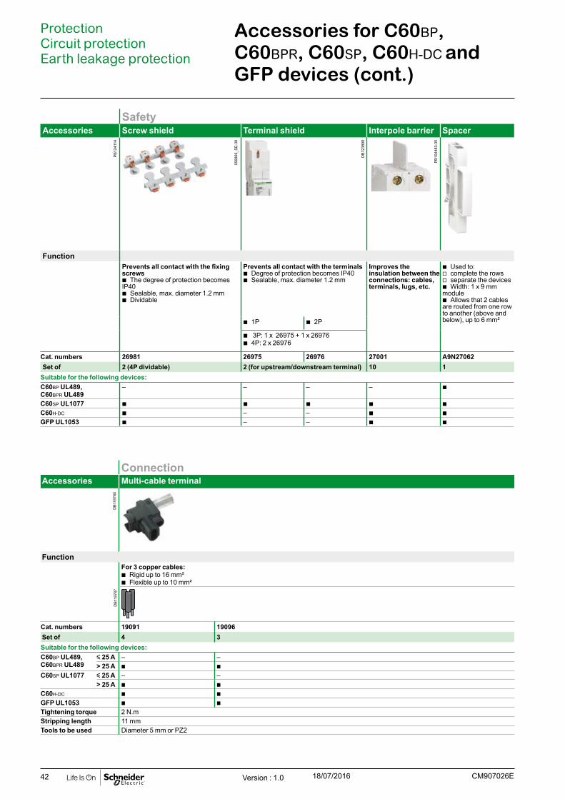
42
SafetyAccessories Screw shield Terminal shield Interpole barrier Spacer
Function Prevents all contact with the fixing screws
b The degree of protection becomes IP40
b Sealable, max. diameter 1.2 mm b Dividable
Prevents all contact with the terminals b Degree of protection becomes IP40 b Sealable, max. diameter 1.2 mm
Improves the insulation between the connections: cables, terminals, lugs, etc.
b Used to: v complete the rows v separate the devices b Width: 1 x 9 mm
module b Allows that 2 cables
are routed from one row to another (above and below), up to 6 mm² b 1P b 2P
b 3P: 1 x 26975 + 1 x 26976 b 4P: 2 x 26976
Cat. numbers 26981 26975 26976 27001 A9N27062Set of 2 (4P dividable) 2 (for upstream/downstream terminal) 10 1
Suitable for the following devices: C60BP UL489,C60BPR UL489
– – – – b
C60SP UL1077 b b b b b C60H-DC b – – b b GFP UL1053 b – – b b
ProtectionCircuit protection Earth leakage protection
Accessories for C60BP, C60BPR, C60SP, C60H-DC and GFP devices (cont.)
ConnectionAccessories Multi-cable terminal
FunctionFor 3 copper cables:
b Rigid up to 16 mm² b Flexible up to 10 mm²
Cat. numbers 19091 19096Set of 4 3Suitable for the following devices:C60BP UL489,C60BPR UL489
y 25 A – –> 25 A b b
C60SP UL1077 y 25 A – –> 25 A b b
C60H-DC b b GFP UL1053 b b Tightening torque 2 N.mStripping length 11 mm Tools to be used Diameter 5 mm or PZ2
Version : 1.0 18/07/2016 CM907026E
DB
1187
80D
B11
8787
0568
69_S
E-3
8
DB
1238
98
PB
1044
83-3
5
PB
1241
14

43Version : 1.0 18/07/2016CM907027E
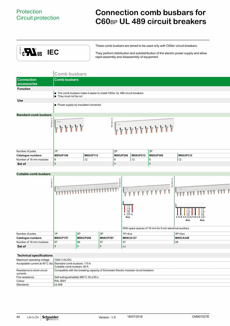
44
Comb busbars AccessoriesConnection accessories
Comb busbars Insulated connectors Tooth covers End-piece
Function b The comb busbars make it easier to install C60BP UL 489 circuit breakers b They must not be cut
b Comb busbar power supply b Vertical incoming feeder
b Insulation of teeth remaining free b Essential to ensure the correctly comb busbars insulation
Use b Power supply by insulated connector b Rigid and flexible copper cable: 6 to 35 mm2
(AWG #10 to #2) b Tightening torque: 3.5 N.m (31 Ib.in).
Standard comb busbars-
Number of poles 1P 2P 3P All All -Catalogue numbers M9XUP106 M9XUP112 M9XUP206 M9XUP212 M9XUP306 M9XUP312 M9XUPC04 M9XCTC18 -Number of 18 mm modules 6 12 6 12 6 12 - - -Set of 1 1 1 4 20 -
Cuttable comb busbars
L LAux. L1 L1L2 L2L3 L3
Aux. Aux.
With spare spaces of 18 mm for 9 mm electrical auxiliary
Number of poles 1P 2P 3P 1P+Aux 3P+Aux All All AllCatalogue numbers M9XCP157 M9XCP256 M9XCP357 M9XCA137 M9XCA348 M9XCPC04 M9XUTC18 M9XCEC10Number of 18 mm modules 57 56 57 37 48 - - -Set of 1 1 1 1 4 20 10
Technical specificationsMaximum operating voltage 1000 V AC/DC 1000 V AC/DC 1000 V AC/DC 1000 V AC/DCAcceptable current at 40°C (Ie) Standard comb busbars: 115 A
Cuttable comb busbars: 80 A- - -
Resistance to short-circuit currents
Compatible with the breaking capacity of Schneider Electric modular circuit breakers Compatible with the breaking capacity of Schneider Electric modular circuit breakers
Compatible with the breaking capacity of Schneider Electric modular circuit breakers
Compatible with the breaking capacity of Schneider Electric modular circuit breakers
Fire resistance Self-extinguishability 960°C 30 s/30 s Self-extinguishability 960°C 30 s/30 s Self-extinguishability 960°C 30 s/30 s Self-extinguishability 960°C 30 s/30 sColour RAL 9001 RAL 9001 RAL 1021 RAL 9001Standards UL508 UL486E - -
Connection comb busbars for C60BP UL 489 circuit breakers
ProtectionCircuit protection
These comb busbars are aimed to be used only with C60BP circuit-breakers.
They perform distribution and subdistribution of the electric power supply and allow rapid assembly and disassembly of equipment.
DB
1238
16
IEC
Version : 1.0 18/07/2016 CM907027E
PB
1166
72-1
4P
B11
6674
-17
PB
1166
75-1
8
PB
1166
76-1
8
PB
1166
73-1
6

45
Comb busbars AccessoriesConnection accessories
Comb busbars Insulated connectors Tooth covers End-piece
Function b The comb busbars make it easier to install C60BP UL 489 circuit breakers b They must not be cut
b Comb busbar power supply b Vertical incoming feeder
b Insulation of teeth remaining free b Essential to ensure the correctly comb busbars insulation
Use b Power supply by insulated connector b Rigid and flexible copper cable: 6 to 35 mm2
(AWG #10 to #2) b Tightening torque: 3.5 N.m (31 Ib.in).
Standard comb busbars-
Number of poles 1P 2P 3P All All -Catalogue numbers M9XUP106 M9XUP112 M9XUP206 M9XUP212 M9XUP306 M9XUP312 M9XUPC04 M9XCTC18 -Number of 18 mm modules 6 12 6 12 6 12 - - -Set of 1 1 1 4 20 -
Cuttable comb busbars
L LAux. L1 L1L2 L2L3 L3
Aux. Aux.
With spare spaces of 18 mm for 9 mm electrical auxiliary
Number of poles 1P 2P 3P 1P+Aux 3P+Aux All All AllCatalogue numbers M9XCP157 M9XCP256 M9XCP357 M9XCA137 M9XCA348 M9XCPC04 M9XUTC18 M9XCEC10Number of 18 mm modules 57 56 57 37 48 - - -Set of 1 1 1 1 4 20 10
Technical specificationsMaximum operating voltage 1000 V AC/DC 1000 V AC/DC 1000 V AC/DC 1000 V AC/DCAcceptable current at 40°C (Ie) Standard comb busbars: 115 A
Cuttable comb busbars: 80 A- - -
Resistance to short-circuit currents
Compatible with the breaking capacity of Schneider Electric modular circuit breakers Compatible with the breaking capacity of Schneider Electric modular circuit breakers
Compatible with the breaking capacity of Schneider Electric modular circuit breakers
Compatible with the breaking capacity of Schneider Electric modular circuit breakers
Fire resistance Self-extinguishability 960°C 30 s/30 s Self-extinguishability 960°C 30 s/30 s Self-extinguishability 960°C 30 s/30 s Self-extinguishability 960°C 30 s/30 sColour RAL 9001 RAL 9001 RAL 1021 RAL 9001Standards UL508 UL486E - -
Connection comb busbars for C60BP UL 489 circuit breakers (cont.)
ProtectionCircuit protection
Version : 1.0 18/07/2016CM907027E
PB
1166
78-2
8P
B11
6679
-27
PB
1166
80-1
8P
B11
6680
-18
PB
1166
77-2
0
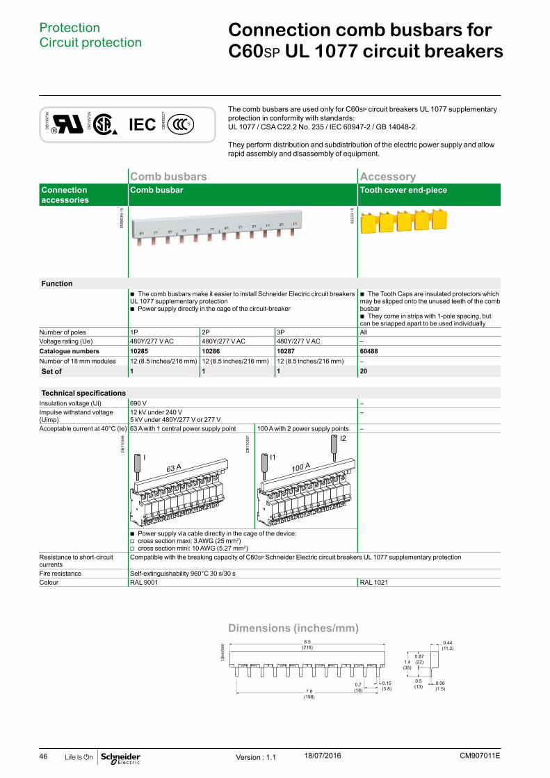
46
Comb busbars AccessoryConnection accessories
Comb busbar Tooth cover end-piece
Function b The comb busbars make it easier to install Schneider Electric circuit breakers
UL 1077 supplementary protection b Power supply directly in the cage of the circuit-breaker
b The Tooth Caps are insulated protectors which may be slipped onto the unused teeth of the comb busbar
b They come in strips with 1-pole spacing, but can be snapped apart to be used individually
Number of poles 1P 2P 3P AllVoltage rating (Ue) 480Y/277 V AC 480Y/277 V AC 480Y/277 V AC –Catalogue numbers 10285 10286 10287 60488Number of 18 mm modules 12 (8.5 inches/216 mm) 12 (8.5 inches/216 mm) 12 (8.5 inches/216 mm) –Set of 1 1 1 20
Technical specificationsInsulation voltage (Ui) 690 V –Impulse withstand voltage (Uimp)
12 kV under 240 V5 kV under 480Y/277 V or 277 V
–
Acceptable current at 40°C (Ie) 63 A with 1 central power supply point 100 A with 2 power supply points –
b Power supply via cable directly in the cage of the device: v cross section maxi: 3 AWG (25 mm2) v cross section mini: 10 AWG (5.27 mm2)
Resistance to short-circuit currents
Compatible with the breaking capacity of C60SP Schneider Electric circuit breakers UL 1077 supplementary protection
Fire resistance Self-extinguishability 960°C 30 s/30 sColour RAL 9001 RAL 1021
Connection comb busbars for C60SP UL 1077 circuit breakers
ProtectionCircuit protection
The comb busbars are used only for C60SP circuit breakers UL 1077 supplementary protection in conformity with standards: UL 1077 / CSA C22.2 No. 235 / IEC 60947-2 / GB 14048-2.
They perform distribution and subdistribution of the electric power supply and allow rapid assembly and disassembly of equipment.
DB
1057
30
DB
1057
29
IEC DB
4052
27
Dimensions (inches/mm)
DB
4059
91
8.5(216)
7.8(198)
0.7(18)
0.15(3.8)
0.06(1.5)
0.5(13)
1.4(35)
0.44(11.2)
0.87(22)
Version : 1.1 18/07/2016 CM907011E
0589
63N
-15
6223
3-10
DB
1103
96
DB
1103
97

47
Complementary technical information
Comb busbars selection guide
Selection guideC60 C60
18 mm
+
With 9 mm auxiliaryDistributed neutral Distributed
Number of poles 18 mm modules Cat. no. Number of poles 18 mm modules Cat. no. Number of poles 18 mm modules Cat. no. Number of poles 18 mm modules Cat. no.1P Aux, L1
L1
6 A9XPH106
L1Aux.
57 A9XAH15712 A9XPH11224 A9XPH12457 A9XPH157
2P Aux, L1, L2
L1 L2
12 A9XPH212
L1 L2Aux.
57 A9XAH25724 A9XPH22457 A9XPH257
3P Aux, L1, L2, L3 Aux, L1, Aux, L2, Aux, L3
L1 L2 L3
6 A9XPH306
L1L2 L3Aux.
57 A9XAH357
L1 L2 L3Aux. Aux. Aux.
57 A9XAH65712 A9XPH31224 A9XPH32457 A9XPH357
3P+N N, L1, N, L2, N, L3 Aux, N, L1, L2, L3 Aux, N, L1, Aux, N, L2, Aux, N, L3
N L1 L2 L3
12 A9XPH412
N N NL1 L2 L3
12 A9XPH512
L1N L2 L3Aux.
57 A9XAH457
N N NL1 L2 L3Aux. Aux. Aux.
57 A9XAH55724 A9XPH424 18 A9XPH51857 A9XPH457 24 A9XPH524
57 A9XPH557
CM907030EVersion : 1.0 18/07/2016
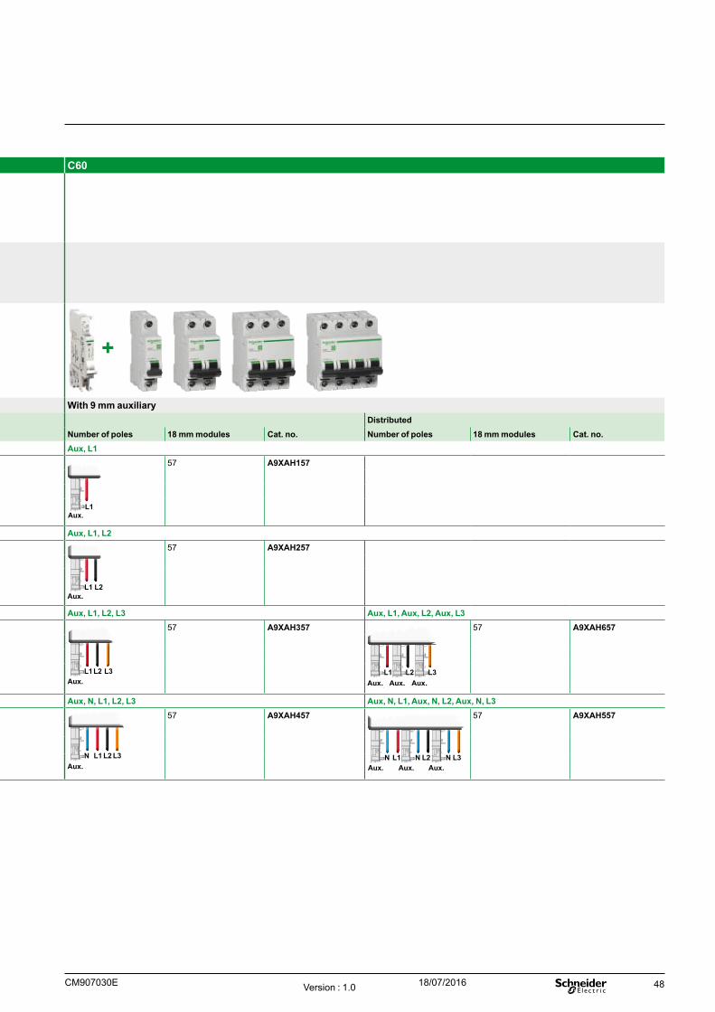
48
Selection guideC60 C60
18 mm
+
With 9 mm auxiliaryDistributed neutral Distributed
Number of poles 18 mm modules Cat. no. Number of poles 18 mm modules Cat. no. Number of poles 18 mm modules Cat. no. Number of poles 18 mm modules Cat. no.1P Aux, L1
L1
6 A9XPH106
L1Aux.
57 A9XAH15712 A9XPH11224 A9XPH12457 A9XPH157
2P Aux, L1, L2
L1 L2
12 A9XPH212
L1 L2Aux.
57 A9XAH25724 A9XPH22457 A9XPH257
3P Aux, L1, L2, L3 Aux, L1, Aux, L2, Aux, L3
L1 L2 L3
6 A9XPH306
L1L2 L3Aux.
57 A9XAH357
L1 L2 L3Aux. Aux. Aux.
57 A9XAH65712 A9XPH31224 A9XPH32457 A9XPH357
3P+N N, L1, N, L2, N, L3 Aux, N, L1, L2, L3 Aux, N, L1, Aux, N, L2, Aux, N, L3
N L1 L2 L3
12 A9XPH412
N N NL1 L2 L3
12 A9XPH512
L1N L2 L3Aux.
57 A9XAH457
N N NL1 L2 L3Aux. Aux. Aux.
57 A9XAH55724 A9XPH424 18 A9XPH51857 A9XPH457 24 A9XPH524
57 A9XPH557
CM907030E Version : 1.0 18/07/2016

49
Complementary technical information
Comb busbars selection guide
Selection guideN40N, N40N Vigi N40N N40N Vigi
9 mm
+ +
With 9 mm auxiliary With 9 mm auxiliaryNumber of poles 18 mm modules Cat. no. Number of poles 18 mm modules Cat. no. Number of poles 18 mm modules Cat. no.
1P+N Aux, N, L Aux, N, L
N L
12 21501
N LAux.
56 A9N21035
18 mm
N LAux.
N LAux.
56 A9N2103718 1951224 2150348 21089
3P+N Aux, N, L1, Aux, N, L2, Aux, N, L3 Aux, N, L1-Aux, N, L2-Aux, N, L3
N N NL1 L2 L3
12 21505
N N NL1 L2 L3Aux. Aux. Aux.
56 A9N21036
18 mm 18 mm18 mm 18 mm
N NN NL2 L3Aux. Aux.Aux. Aux.
NN L1Aux.Aux.
56 A9N21038
18 19516
24 21507
48 21093
CM907030EVersion : 1.0 18/07/2016
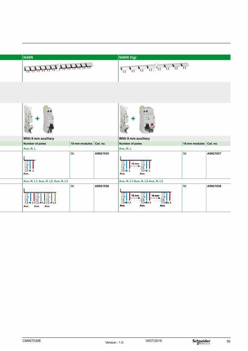
50
Selection guideN40N, N40N Vigi N40N N40N Vigi
9 mm
+ +
With 9 mm auxiliary With 9 mm auxiliaryNumber of poles 18 mm modules Cat. no. Number of poles 18 mm modules Cat. no. Number of poles 18 mm modules Cat. no.
1P+N Aux, N, L Aux, N, L
N L
12 21501
N LAux.
56 A9N21035
18 mm
N LAux.
N LAux.
56 A9N2103718 1951224 2150348 21089
3P+N Aux, N, L1, Aux, N, L2, Aux, N, L3 Aux, N, L1-Aux, N, L2-Aux, N, L3
N N NL1 L2 L3
12 21505
N N NL1 L2 L3Aux. Aux. Aux.
56 A9N21036
18 mm 18 mm18 mm 18 mm
N NN NL2 L3Aux. Aux.Aux. Aux.
NN L1Aux.Aux.
56 A9N21038
18 19516
24 21507
48 21093
CM907030E Version : 1.0 18/07/2016
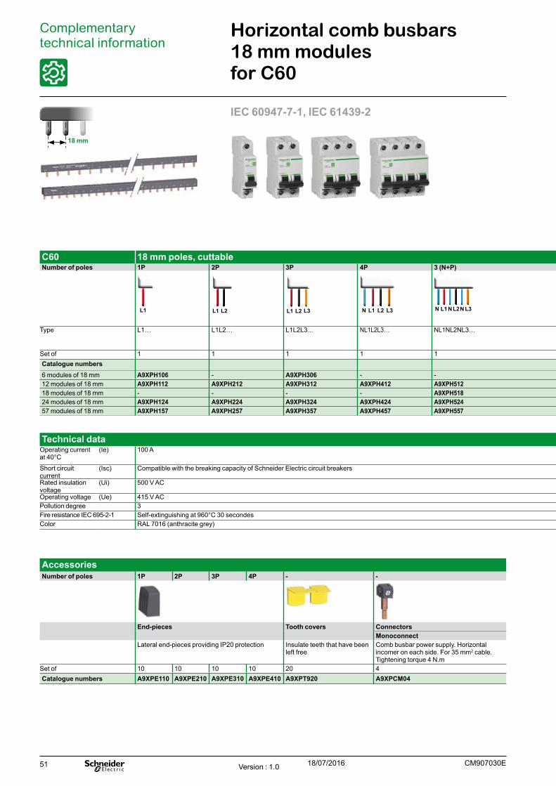
51
Horizontal comb busbars 18 mm modules for C60
Complementary technical information
IEC 60947-7-1, IEC 61439-2
AccessoriesNumber of poles 1P 2P 3P 4P - -
End-pieces Tooth covers ConnectorsMonoconnect
Lateral end-pieces providing IP20 protection Insulate teeth that have been left free
Comb busbar power supply. Horizontal incomer on each side. For 35 mm2 cable. Tightening torque 4 N.m
Set of 10 10 10 10 20 4Catalogue numbers A9XPE110 A9XPE210 A9XPE310 A9XPE410 A9XPT920 A9XPCM04
18 mm
Technical dataOperating current at 40°C
(Ie) 100 A
Short circuit current
(Isc) Compatible with the breaking capacity of Schneider Electric circuit breakers
Rated insulation voltage
(Ui) 500 V AC
Operating voltage (Ue) 415 V ACPollution degree 3Fire resistance IEC 695-2-1 Self-extinguishing at 960°C 30 secondesColor RAL 7016 (anthracite grey)
C60 18 mm poles, cuttable Cuttable comb busbars, 18 mm modules, with 9 mm auxiliaryNumber of poles 1P 2P 3P 4P 3 (N+P) Aux+1P Aux+2P Aux+3P Aux+4P 3 (Aux+1P) 3 (Aux+N+1P)
L1 L1 L2 L1 L2 L3 N L1 L2 L3 N N NL1 L2 L3 L1Aux.
L1 L2Aux. L1L2 L3
Aux.
L1N L2 L3Aux.
L1 L2 L3Aux. Aux. Aux.
N N NL1 L2 L3Aux. Aux. Aux.
Type L1… L1L2… L1L2L3... NL1L2L3… NL1NL2NL3… AuxL1... AuxL1L2… AuxL1L2L3… AuxNL1L2L3… AuxL1AuxL2AuxL3… AuxL1AuxL2AuxL3…
Set of 1 1 1 1 1 1 1 1 1 1 1Catalogue numbers6 modules of 18 mm A9XPH106 - A9XPH306 - - - - - - - -12 modules of 18 mm A9XPH112 A9XPH212 A9XPH312 A9XPH412 A9XPH512 - - - - - -18 modules of 18 mm - - - - A9XPH518 - - - - - -24 modules of 18 mm A9XPH124 A9XPH224 A9XPH324 A9XPH424 A9XPH524 - - - - - -57 modules of 18 mm A9XPH157 A9XPH257 A9XPH357 A9XPH457 A9XPH557 A9XAH157 A9XAH257 A9XAH357 A9XAH457 A9XAH657 A9XAH557
CM907030EVersion : 1.0 18/07/2016

52
Technical dataOperating current at 40°C
(Ie) 100 A
Short circuit current
(Isc) Compatible with the breaking capacity of Schneider Electric circuit breakers
Rated insulation voltage
(Ui) 500 V AC
Operating voltage (Ue) 415 V ACPollution degree 3Fire resistance IEC 695-2-1 Self-extinguishing at 960°C 30 secondesColor RAL 7016 (anthracite grey)
C60 18 mm poles, cuttable Cuttable comb busbars, 18 mm modules, with 9 mm auxiliaryNumber of poles 1P 2P 3P 4P 3 (N+P) Aux+1P Aux+2P Aux+3P Aux+4P 3 (Aux+1P) 3 (Aux+N+1P)
L1 L1 L2 L1 L2 L3 N L1 L2 L3 N N NL1 L2 L3 L1Aux.
L1 L2Aux. L1L2 L3
Aux.
L1N L2 L3Aux.
L1 L2 L3Aux. Aux. Aux.
N N NL1 L2 L3Aux. Aux. Aux.
Type L1… L1L2… L1L2L3... NL1L2L3… NL1NL2NL3… AuxL1... AuxL1L2… AuxL1L2L3… AuxNL1L2L3… AuxL1AuxL2AuxL3… AuxL1AuxL2AuxL3…
Set of 1 1 1 1 1 1 1 1 1 1 1Catalogue numbers6 modules of 18 mm A9XPH106 - A9XPH306 - - - - - - - -12 modules of 18 mm A9XPH112 A9XPH212 A9XPH312 A9XPH412 A9XPH512 - - - - - -18 modules of 18 mm - - - - A9XPH518 - - - - - -24 modules of 18 mm A9XPH124 A9XPH224 A9XPH324 A9XPH424 A9XPH524 - - - - - -57 modules of 18 mm A9XPH157 A9XPH257 A9XPH357 A9XPH457 A9XPH557 A9XAH157 A9XAH257 A9XAH357 A9XAH457 A9XAH657 A9XAH557
+
CM907030E Version : 1.0 18/07/2016
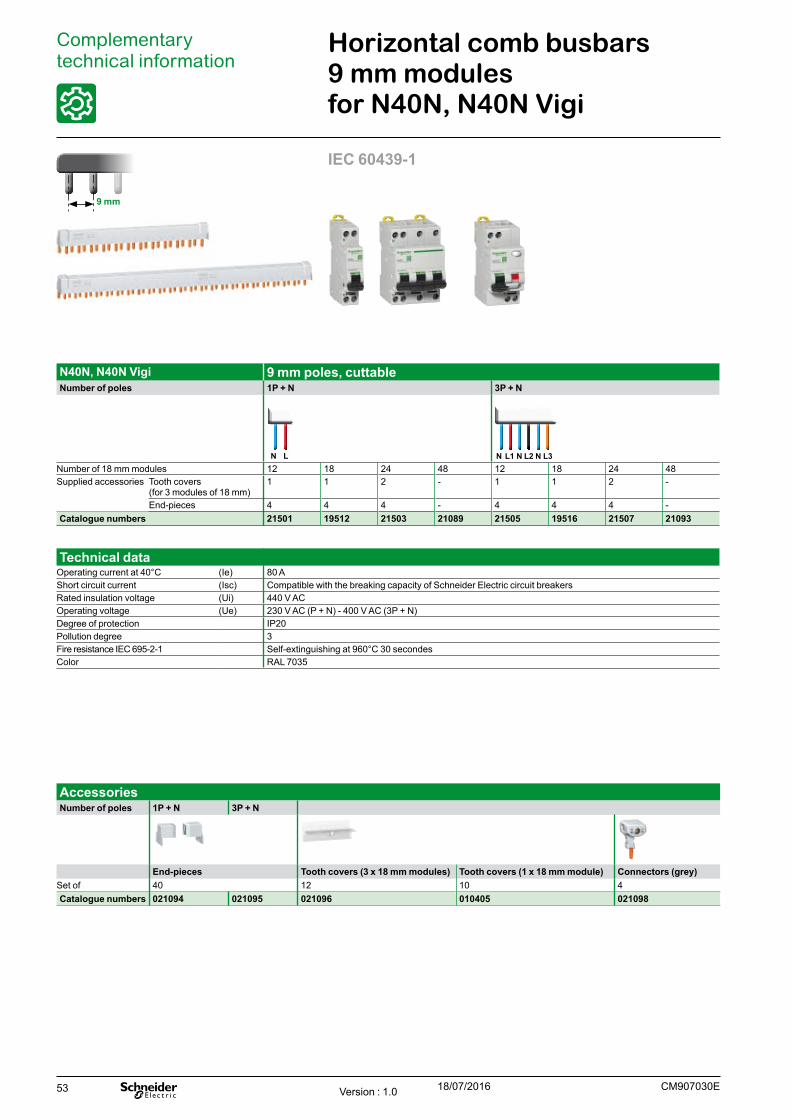
53
Complementary technical information
IEC 60439-1
Horizontal comb busbars 9 mm modules for N40N, N40N Vigi
N40N, N40N Vigi 9 mm poles, cuttableNumber of poles 1P + N 3P + N
N L N N NL1 L2 L3Number of 18 mm modules 12 18 24 48 12 18 24 48Supplied accessories Tooth covers
(for 3 modules of 18 mm)1 1 2 - 1 1 2 -
End-pieces 4 4 4 - 4 4 4 -Catalogue numbers 21501 19512 21503 21089 21505 19516 21507 21093
AccessoriesNumber of poles 1P + N 3P + N
End-pieces Tooth covers (3 x 18 mm modules) Tooth covers (1 x 18 mm module) Connectors (grey)Set of 40 12 10 4Catalogue numbers 021094 021095 021096 010405 021098
9 mm
Technical dataOperating current at 40°C (Ie) 80 AShort circuit current (Isc) Compatible with the breaking capacity of Schneider Electric circuit breakersRated insulation voltage (Ui) 440 V ACOperating voltage (Ue) 230 V AC (P + N) - 400 V AC (3P + N)Degree of protection IP20Pollution degree 3Fire resistance IEC 695-2-1 Self-extinguishing at 960°C 30 secondesColor RAL 7035
CM907030EVersion : 1.0 18/07/2016
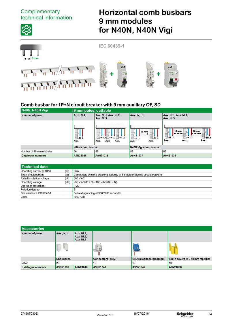
54
Comb busbar for 1P+N circuit breaker with 9 mm auxiliary OF, SDN40N, N40N Vigi 9 mm poles, cuttableNumber of poles Aux., N, L Aux. NL1, Aux. NL2,
Aux. NL3Aux., N, L1 Aux. NL1, Aux. NL2,
Aux. NL3
N LAux.
N N NL1 L2 L3Aux. Aux. Aux.
18 mm
N LAux.
N LAux.
18 mm 18 mm18 mm 18 mm
N NN NL2 L3Aux. Aux.Aux. Aux.
NN L1Aux.Aux.
N40N comb busbar N40N Vigi comb busbarNumber of 18 mm modules 56 56 56 56Catalogue numbers A9N21035 A9N21036 A9N21037 A9N21038
AccessoriesNumber of poles Aux., N, L Aux. NL1,
Aux. NL2, Aux. NL3
End-pieces Connectors (grey) Neutral connectors (bleu) Tooth covers (1 x 18 mm module)Set of 20 10 10 10Catalogue numbers A9N21039 A9N21040 A9N21041 A9N21042 A9N21050
Complementary technical information
Horizontal comb busbars 9 mm modules for N40N, N40N Vigi
IEC 60439-1
9 mm
Technical dataOperating current at 40°C (Ie) 63 AShort circuit current (Isc) Compatible with the breaking capacity of Schneider Electric circuit breakersRated insulation voltage (Ui) 500 V ACOperating voltage (Ue) 230 V AC (P + N) - 400 V AC (3P + N)Degree of protection IP20Pollution degree 3Fire resistance IEC 695-2-1 Self-extinguishing at 960°C 30 secondesColor RAL 7035
+ +
CM907030E Version : 1.0 18/07/2016

55Version : 1.3 18/07/2016CA907023E

56
Linergy DSScrew distribution blocks
IEC/EN 60947-7-1, IEC/EN 61439-1 & 2
Description b Single-pole or four-pole distribution block that can be installed on a standard DIN
rail or on a mounting plate. b Compatible with Prisma G and P, Pragma, Mini Pragma and Resbo series
switchboards. b Incomers and feeders are connected to screw terminals that accept rigid or
flexible cables with ferrule. b Optional: additional neutral terminal strip for four-pole distribution block.
Advantages b Simplified power supply for main incomers. b Easy phase balancing. b Easy, effortless cabling due to excellent accessibility. b Visible cabling. b Insulation between phases. b The single-pole distribution blocks are adjacent and bridgeable via the second
incoming hole for parallel connection.
Screw distribution blocksNumber of poles 1P 4P Neutral terminal strip
PB
1112
50-2
0_1.
eps
PB
1112
51-2
0_1.
eps
PB
1112
52-2
0_1.
eps
PB
1112
43-2
0_1.
eps
PB
1112
44-2
0_1.
eps
PB
1112
45-2
0_1.
eps
PB
1112
46-2
0_1.
eps
PB
1112
47-2
0_1.
eps
PB
1112
48-2
0_1.
eps
PB
1112
49-2
0_1.
eps
Rated operational current 125 A 160 A 250 A 100 A 125 A 160 A 100 A 125 ATotal connections capacity 10 13 14 4 x 7 4 x 12 4 x 15 4 x 12 7 12 15Terminal capacity
Diameter 2 x Ø 9.5 mm 2 x Ø 12 mm 1 x Ø 15.3 mm 2 x Ø 7.5 mm 1 x Ø 9 mm 1 x Ø 9.5 mm 1 x Ø 12 mm 2 x Ø 7.5 mm 1 x Ø 9 mm 1 x Ø 9.5 mm
2 x Ø 7.5 mm 3 x Ø 7.5 mm 1 x Ø 10 mm 5 x Ø 5.5 mm 7 x Ø 7.5 mm 3 x Ø 8.5 mm 3 x Ø 9 mm 5 x Ø 5.5 mm 7 x Ø 7.5 mm 3 x Ø 8.5 mm6 x Ø 5.8 mm 8 x Ø 5.8 mm 4 x Ø 6 mm - 4 x Ø 6.5 mm 11 x Ø 6.5 mm 8 x Ø 7.5 mm - 4 x Ø 6.5 mm 11 x Ø 6.5 mm- - 8 x Ø 7.5 mm - - - - - - -
Rated peak withstand current (Ipk)
Ipk/60 ms 25 k 36 k 60 k 14 k 18 k 18 k 22 k - - -Ipk/6 ms - - - 24 k 26 k 28 k 36 k - - -
Rated short-time withstand current (Icw) (IEC/EN 60947-7-1)
4.2 kA rms/1 s 8.4 kA rms/1 s 14.4 kA rms/1 s 3 kA rms/1 s 4.2 kA rms/1 s 4.2 kA rms/1 s 8.4 kA rms/1 s - - -
Width (number of 9 mm pitches)
3 4 5 8 14 20 18 7 14 17
Dimension (H x W x D) 85 x 27 x 50.5 85 x 36 x 50.5 85 x 45 x 50.5 100 x 71 x 50.5 100 x 126 x 50.5 100 x 162 x 50.5 100 x 174 x 50.5 20 x 70 x 35 20 x 125 x 35 20 x 155 x 35Weight (g) 125 163 239 210 390 559 567 63 111 149Neutral terminal strip (optional) - - - LGYN1007 LGYN12512 LGYN12515 LGYN12512 - - -References LGY112510 LGY116013 LGY125014 LGY410028 LGY412548 LGY412560 LGY416048 LGYN1007 LGYN12512 LGYN12515
PB
1112
54-3
0_1.
eps
PB
1112
53-3
0_1.
eps
Linergy distribution systems Distribution blocks
Version : 1.3 18/07/2016 CA907023E
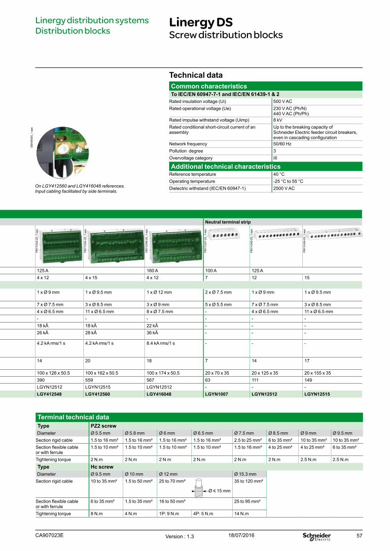
57
Screw distribution blocksNumber of poles 1P 4P Neutral terminal strip
PB
1112
50-2
0_1.
eps
PB
1112
51-2
0_1.
eps
PB
1112
52-2
0_1.
eps
PB
1112
43-2
0_1.
eps
PB
1112
44-2
0_1.
eps
PB
1112
45-2
0_1.
eps
PB
1112
46-2
0_1.
eps
PB
1112
47-2
0_1.
eps
PB
1112
48-2
0_1.
eps
PB
1112
49-2
0_1.
eps
Rated operational current 125 A 160 A 250 A 100 A 125 A 160 A 100 A 125 ATotal connections capacity 10 13 14 4 x 7 4 x 12 4 x 15 4 x 12 7 12 15Terminal capacity
Diameter 2 x Ø 9.5 mm 2 x Ø 12 mm 1 x Ø 15.3 mm 2 x Ø 7.5 mm 1 x Ø 9 mm 1 x Ø 9.5 mm 1 x Ø 12 mm 2 x Ø 7.5 mm 1 x Ø 9 mm 1 x Ø 9.5 mm
2 x Ø 7.5 mm 3 x Ø 7.5 mm 1 x Ø 10 mm 5 x Ø 5.5 mm 7 x Ø 7.5 mm 3 x Ø 8.5 mm 3 x Ø 9 mm 5 x Ø 5.5 mm 7 x Ø 7.5 mm 3 x Ø 8.5 mm6 x Ø 5.8 mm 8 x Ø 5.8 mm 4 x Ø 6 mm - 4 x Ø 6.5 mm 11 x Ø 6.5 mm 8 x Ø 7.5 mm - 4 x Ø 6.5 mm 11 x Ø 6.5 mm- - 8 x Ø 7.5 mm - - - - - - -
Rated peak withstand current (Ipk)
Ipk/60 ms 25 k 36 k 60 k 14 k 18 k 18 k 22 k - - -Ipk/6 ms - - - 24 k 26 k 28 k 36 k - - -
Rated short-time withstand current (Icw) (IEC/EN 60947-7-1)
4.2 kA rms/1 s 8.4 kA rms/1 s 14.4 kA rms/1 s 3 kA rms/1 s 4.2 kA rms/1 s 4.2 kA rms/1 s 8.4 kA rms/1 s - - -
Width (number of 9 mm pitches)
3 4 5 8 14 20 18 7 14 17
Dimension (H x W x D) 85 x 27 x 50.5 85 x 36 x 50.5 85 x 45 x 50.5 100 x 71 x 50.5 100 x 126 x 50.5 100 x 162 x 50.5 100 x 174 x 50.5 20 x 70 x 35 20 x 125 x 35 20 x 155 x 35Weight (g) 125 163 239 210 390 559 567 63 111 149Neutral terminal strip (optional) - - - LGYN1007 LGYN12512 LGYN12515 LGYN12512 - - -References LGY112510 LGY116013 LGY125014 LGY410028 LGY412548 LGY412560 LGY416048 LGYN1007 LGYN12512 LGYN12515
Technical dataCommon characteristicsTo IEC/EN 60947-7-1 and IEC/EN 61439-1 & 2
Rated insulation voltage (Ui) 500 V ACRated operational voltage (Ue) 230 V AC (Ph/N)
440 V AC (Ph/Ph)Rated impulse withstand voltage (Uimp) 8 kVRated conditional short-circuit current of an assembly
Up to the breaking capacity of Schneider Electric feeder circuit breakers, even in cascading configuration
Network frequency 50/60 HzPollution degree 3Overvoltage category III
Additional technical characteristicsReference temperature 40 °COperating temperature -25 °C to 55 °CDielectric withstand (IEC/EN 60947-1) 2500 V AC
Linergy DSScrew distribution blocks
On LGY412560 and LGY416048 references.Input cabling facilitated by side terminals.
Terminal technical dataType PZ2 screwDiameter Ø 5.5 mm Ø 5.8 mm Ø 6 mm Ø 6.5 mm Ø 7.5 mm Ø 8.5 mm Ø 9 mm Ø 9.5 mm
Section rigid cable 1.5 to 16 mm² 1.5 to 16 mm² 1.5 to 16 mm² 1.5 to 16 mm² 2.5 to 25 mm² 6 to 35 mm² 10 to 35 mm² 10 to 35 mm²Section flexible cable or with ferrule
1.5 to 10 mm² 1.5 to 10 mm² 1.5 to 10 mm² 1.5 to 10 mm² 1.5 to 16 mm² 4 to 25 mm² 4 to 25 mm² 6 to 35 mm²
Tightening torque 2 N.m 2 N.m 2 N.m 2 N.m 2 N.m 2 N.m 2.5 N.m 2.5 N.mType Hc screwDiameter Ø 9.5 mm Ø 10 mm Ø 12 mm Ø 15.3 mm
Section rigid cable 10 to 35 mm² 1.5 to 50 mm² 25 to 70 mm²
Ø y 15 mm
35 to 120 mm²
Section flexible cable or with ferrule
6 to 35 mm² 1.5 to 35 mm² 16 to 50 mm² 25 to 95 mm²
Tightening torque 8 N.m 4 N.m 1P: 9 N.m 4P: 5 N.m 14 N.m
DB
4060
05_1
.eps
Linergy distribution systems Distribution blocks
Version : 1.3 18/07/2016CA907023E
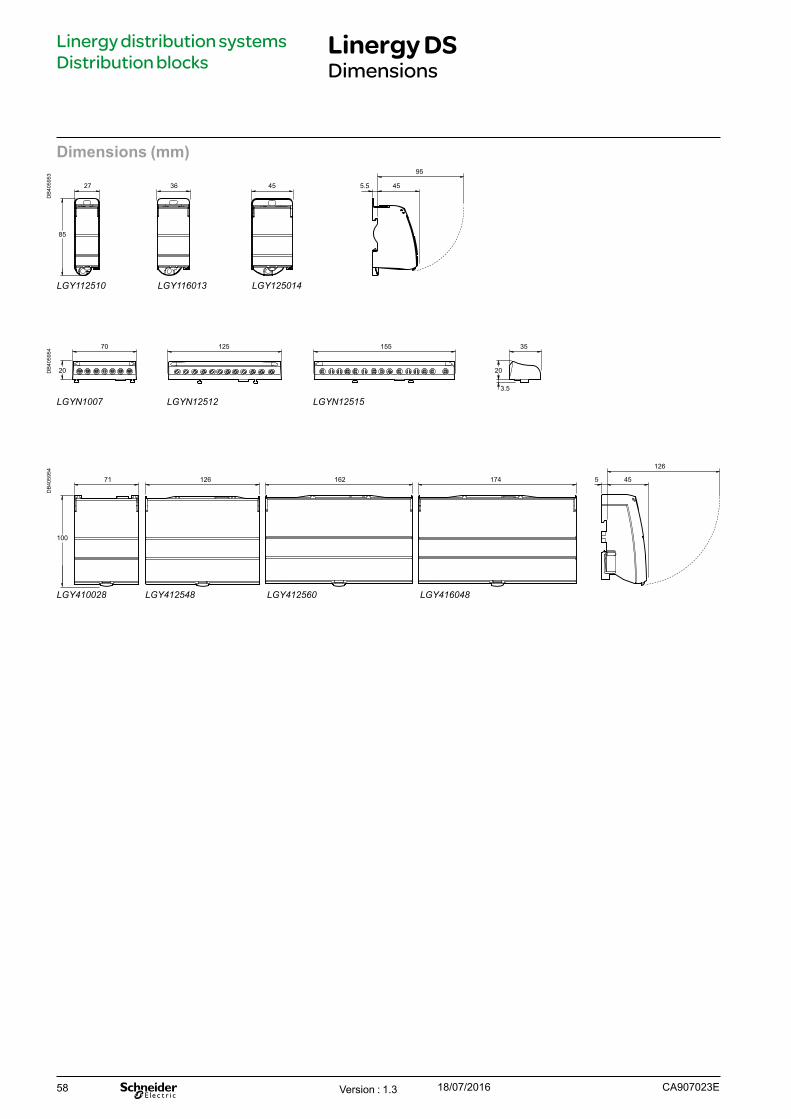
58
Linergy DSDimensions
Linergy distribution systems Distribution blocks
Dimensions (mm)
DB
4059
53
27 36 45 455.5
95
85
LGY112510 LGY116013 LGY125014
DB
4059
54
70 125 155 35
2020
3.5
LGYN1007 LGYN12512 LGYN12515
DB
4059
54
71 126 162 174 5 45
126
100
LGY410028 LGY412548 LGY412560 LGY416048
Version : 1.3 18/07/2016 CA907023E
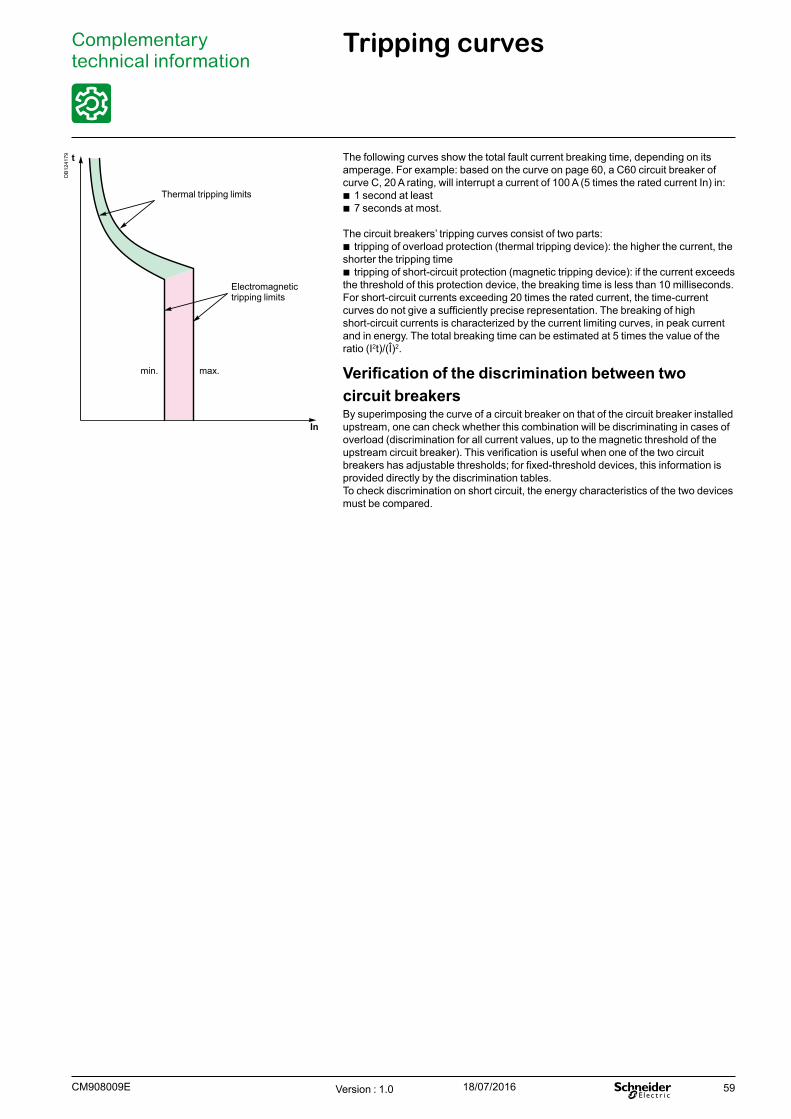
59
Complementary technical information
Tripping curves
In
t
Thermal tripping limits
Electromagnetic tripping limits
min. max.
The following curves show the total fault current breaking time, depending on its amperage. For example: based on the curve on page 60, a C60 circuit breaker of curve C, 20 A rating, will interrupt a current of 100 A (5 times the rated current In) in:
b 1 second at least b 7 seconds at most.
The circuit breakers’ tripping curves consist of two parts: b tripping of overload protection (thermal tripping device): the higher the current, the
shorter the tripping time b tripping of short-circuit protection (magnetic tripping device): if the current exceeds
the threshold of this protection device, the breaking time is less than 10 milliseconds.For short-circuit currents exceeding 20 times the rated current, the time-current curves do not give a sufficiently precise representation. The breaking of high short-circuit currents is characterized by the current limiting curves, in peak current and in energy. The total breaking time can be estimated at 5 times the value of the ratio (I2t)/(Î)2.
Verification of the discrimination between two circuit breakers By superimposing the curve of a circuit breaker on that of the circuit breaker installed upstream, one can check whether this combination will be discriminating in cases of overload (discrimination for all current values, up to the magnetic threshold of the upstream circuit breaker). This verification is useful when one of the two circuit breakers has adjustable thresholds; for fixed-threshold devices, this information is provided directly by the discrimination tables.To check discrimination on short circuit, the energy characteristics of the two devices must be compared.
Version : 1.0 18/07/2016CM908009E
DB
1241
79
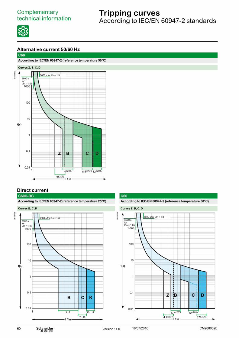
60
Complementary technical information
Tripping curvesAccording to IEC/EN 60947-2 standards
Alternative current 50/60 HzC60According to IEC/EN 60947-2 (reference temperature 50°C)
Curves Z, B, C, D
DB
4085
02
t(s)
0,01
0,1
1
10
100
1000
C DB
I / In
1 4±20% 8.5±20% 12±20%
3±20%
Z
3600 s for I/In= 1.3 3600 sforI/In = 1.05
Direct currentC60H-DC C60According to IEC/EN 60947-2 (reference temperature 25°C) According to IEC/EN 60947-2 (reference temperature 50°C)
Curves B, C, K Curves Z, B, C, D
DB
4061
78
t(s)
0.01
0.1
1
10
100
1000
I / In
1 3...7 10...14
7...10
B C K
3600 sforI/In = 1.05
3600 s for I/In = 1.3 DB
4085
03
t(s)
0.01
0.1
1
10
100
1000
I / In
1 5.7±20%
BZ C D
12±20%
17±20%4.2±20%
3600 sforI/In = 1.05
3600 s for I/In = 1.3
Version : 1.0 18/07/2016 CM908009E


Schneider Electric Industries SAS
© 2016 - Schneider Electric. All Rights Reserved.All trademarks are owned by Schneider Electric Industries SAS or its affiliated companies. This document has been
printed on recycled paper
35, rue Joseph MonierCS 3032392506 Rueil Malmaison Cedex France
RCS Nanterre 954 503 439Capital social 896 313 776 €www.schneider-electric.com
07-2016CM909007