muck-truck mk iv dumper max mk ii dumper - muck truck home
TRANSCRIPT
ModelsMuck-Truck Mk IV DumperMAX Mk II DumperStarting with Serial Number 101
Muck-Truck Mk IV DumperMAX Mk II Dumper
03737210 12/08Printed in USA
Owner, Operation, Accessories & Parts Manual
ENGLISH

GB – 2
ASSEMBLY. . . . . . . . . . . . . . . . . . . . . . . . . . . . . . . . . 3
SAFETY . . . . . . . . . . . . . . . . . . . . . . . . . . . . . . . . . . . 4
CONTROLS AND FEATURES . . . . . . . . . . . . . . . . . . 5
OPERATION . . . . . . . . . . . . . . . . . . . . . . . . . . . . . . . . 6
MAINTENANCE . . . . . . . . . . . . . . . . . . . . . . . . . . . . . 8
SERVICE AND ADJUSTMENTS. . . . . . . . . . . . . . . . . 9
PARTS LIST . . . . . . . . . . . . . . . . . . . . . . . . . . . . . . . 12
ACCESSORIES. . . . . . . . . . . . . . . . . . . . . . . . . . . . .18
WARRANTY . . . . . . . . . . . . . . . . . . . . . . . . . . . . . . . 28
THE MANUALBefore using the unit, carefully and completely read your manual. The contents will give you an understanding of safety instructions and controls during normal operation and maintenance.All reference to left, right, front, or rear are given from the operator’s position, facing the direction of forward travel.
ENGINE MANUALThe engine on this unit is covered by a separate manual specific to the engine. This manual is included in the literature package that shipped with the unit. Refer to this manual for engine service recommendations. If the engine manual is not available, contact the engine manufacturer for a replacement manual.
PURCHASE INFORMATIONPlease record the following information about your unit and have it available before contacting us.Serial Number:
Dealer/Distributor’s Name:
Date of Purchase:
Year of Manufacture:
The undersigned of Niche Product Sales LLC declare that the Pedestrian Dumper Trucks:Category: Gasoline 4-Stroke Pedestrian DumperModel: Muck-Truck Mk IV Dumper / MAX Mk II DumperConform with the essential Health and Safety requirements of the EEC Directive.98/37/EC (Edition L 207)Previously 89/392/EEC – 93/94/EEC AmendmentBasic Noise Emission Standard – EN ISO 3744 – dB 97 Lwa
H.A.V.sMachinery Directive 89/392/EECThe supply of (Safety) regulations 1992 (as amended: 1994), for conformity in an EU market
Specified testing unit to: ISO 8041, ISO 5349 and BS 6842Place: 586 Mercantile PlacePort St. Lucie, Florida 34986 USA
Name and signature of Technical Manager of Niche Product Sales LLC.
Terry Rowlands
TABLE OF CONTENTS
INTRODUCTION
DECLARATION OF CONFORMITY
Left Hand Idle : 2.79 m/s2 Right Hand Idle : 3.10 m/s2
Racing : 4.95 m/s2 Racing : 5.86 m/s2
© Copyright 2008 Niche Product Sales LLC
GB – 3
Remove From Crate1. Remove crate top and sides.
2. Remove protective plastic covering.
3. Remove 5/16 x 2" hex bolts from Manual Package.
4. Cut and remove four plastic shipping bands from axles.
Unit can remain on crate base during handle installation.
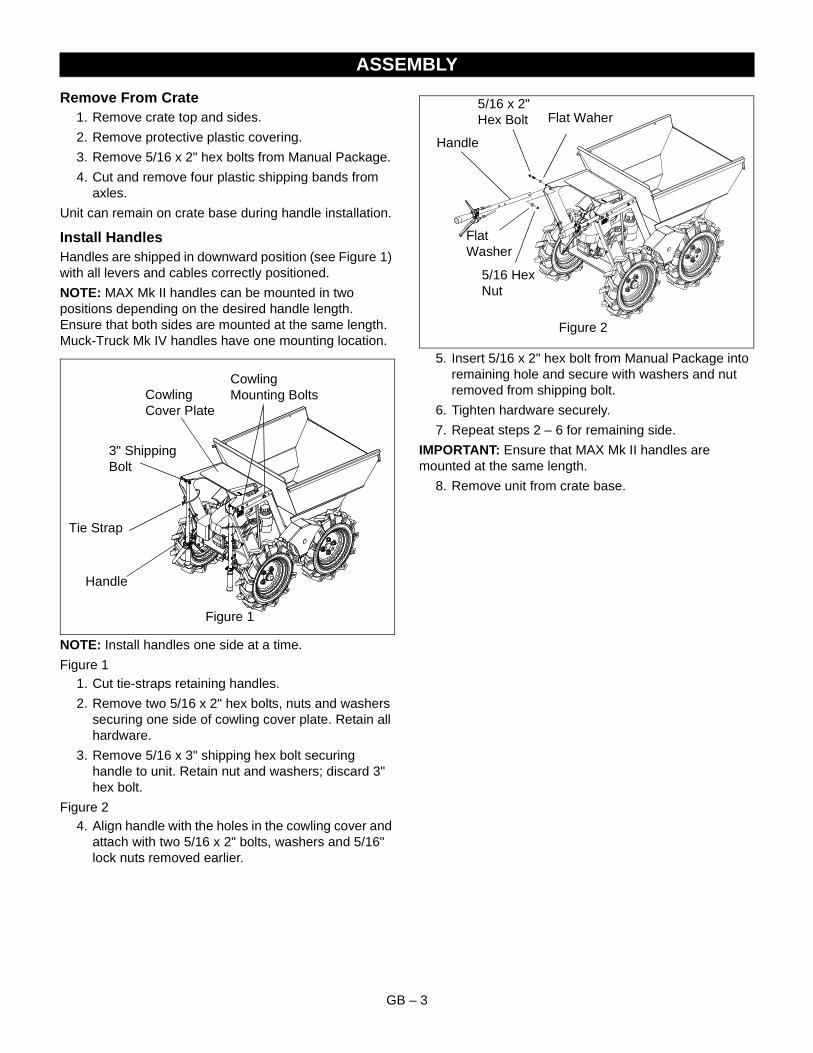
Install HandlesHandles are shipped in downward position (see Figure 1) with all levers and cables correctly positioned.
NOTE: MAX Mk II handles can be mounted in two positions depending on the desired handle length. Ensure that both sides are mounted at the same length. Muck-Truck Mk IV handles have one mounting location.
NOTE: Install handles one side at a time.
Figure 11. Cut tie-straps retaining handles.
2. Remove two 5/16 x 2" hex bolts, nuts and washers securing one side of cowling cover plate. Retain all hardware.
3. Remove 5/16 x 3" shipping hex bolt securing handle to unit. Retain nut and washers; discard 3" hex bolt.
Figure 24. Align handle with the holes in the cowling cover and
attach with two 5/16 x 2" bolts, washers and 5/16" lock nuts removed earlier.
5. Insert 5/16 x 2" hex bolt from Manual Package into remaining hole and secure with washers and nut removed from shipping bolt.
6. Tighten hardware securely.
7. Repeat steps 2 – 6 for remaining side.
IMPORTANT: Ensure that MAX Mk II handles are mounted at the same length.
8. Remove unit from crate base.
ASSEMBLY
Figure 1
Tie Strap
3" Shipping Bolt
Handle
Cowling Mounting BoltsCowling
Cover Plate
Figure 2
Handle
5/16 x 2" Hex Bolt
5/16 Hex Nut
Flat Waher
Flat Washer
GB – 4
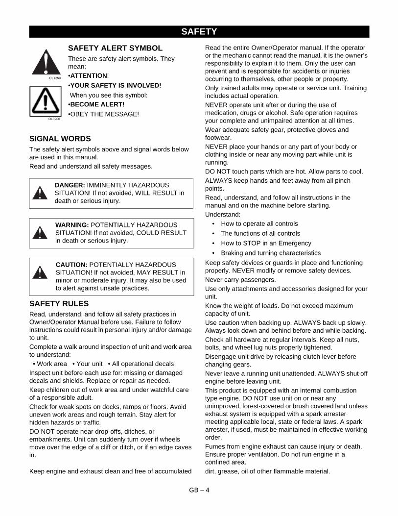
SAFETY ALERT SYMBOLThese are safety alert symbols. They mean: •ATTENTION!
•YOUR SAFETY IS INVOLVED!
When you see this symbol:•BECOME ALERT!
•OBEY THE MESSAGE!
SIGNAL WORDSThe safety alert symbols above and signal words below are used in this manual.Read and understand all safety messages.
SAFETY RULESRead, understand, and follow all safety practices in Owner/Operator Manual before use. Failure to follow instructions could result in personal injury and/or damage to unit.Complete a walk around inspection of unit and work area to understand: • Work area • Your unit • All operational decalsInspect unit before each use for: missing or damaged decals and shields. Replace or repair as needed.Keep children out of work area and under watchful care of a responsible adult.Check for weak spots on docks, ramps or floors. Avoid uneven work areas and rough terrain. Stay alert for hidden hazards or traffic.DO NOT operate near drop-offs, ditches, or embankments. Unit can suddenly turn over if wheels move over the edge of a cliff or ditch, or if an edge caves in.
Read the entire Owner/Operator manual. If the operator or the mechanic cannot read the manual, it is the owner’s responsibility to explain it to them. Only the user can prevent and is responsible for accidents or injuries occurring to themselves, other people or property.Only trained adults may operate or service unit. Training includes actual operation.NEVER operate unit after or during the use of medication, drugs or alcohol. Safe operation requires your complete and unimpaired attention at all times.Wear adequate safety gear, protective gloves and footwear.NEVER place your hands or any part of your body or clothing inside or near any moving part while unit is running.DO NOT touch parts which are hot. Allow parts to cool.ALWAYS keep hands and feet away from all pinch points.Read, understand, and follow all instructions in the manual and on the machine before starting.Understand:
• How to operate all controls
• The functions of all controls
• How to STOP in an Emergency
• Braking and turning characteristics
Keep safety devices or guards in place and functioning properly. NEVER modify or remove safety devices.Never carry passengers.Use only attachments and accessories designed for your unit.Know the weight of loads. Do not exceed maximum capacity of unit.Use caution when backing up. ALWAYS back up slowly. Always look down and behind before and while backing.Check all hardware at regular intervals. Keep all nuts, bolts, and wheel lug nuts properly tightened.Disengage unit drive by releasing clutch lever before changing gears.Never leave a running unit unattended. ALWAYS shut off engine before leaving unit. This product is equipped with an internal combustion type engine. DO NOT use unit on or near any unimproved, forest-covered or brush covered land unless exhaust system is equipped with a spark arrester meeting applicable local, state or federal laws. A spark arrester, if used, must be maintained in effective working order.Fumes from engine exhaust can cause injury or death. Ensure proper ventilation. Do not run engine in a confined area.
Keep engine and exhaust clean and free of accumulated dirt, grease, oil of other flammable material.
SAFETY
DANGER: IMMINENTLY HAZARDOUS SITUATION! If not avoided, WILL RESULT in death or serious injury.
WARNING: POTENTIALLY HAZARDOUS SITUATION! If not avoided, COULD RESULT in death or serious injury.
CAUTION: POTENTIALLY HAZARDOUS SITUATION! If not avoided, MAY RESULT in minor or moderate injury. It may also be used to alert against unsafe practices.
OL1253
OL3900
GB – 5
Do not use a pressure washer directly on engine electronics.Fuel is highly flammable and its vapors are explosive. Handle with care. Use an approved fuel container.NO smoking, NO sparks, NO flames. NEVER fill fuel tank when engine is running or hot from operation, or if an open flame or cigarette is present.NEVER fill or drain fuel tank indoors.Replace fuel cap securely and clean up spilled fuel.Never fill containers inside a vehicle or on a truck or trailer bed with a plastic liner. Always place containers on the ground away from vehicle before filling.
Keep fuel nozzle in contact with the rim of the fuel tank or container opening at all times until fueling is complete. Do not use a nozzle lock-open device.If fuel is spilled on clothing, change clothing immediately.DO NOT change engine governor settings or over-speed engine. A damaged or worn out muffler can cause fire or explosion. Replace with manufacturer-recommend parts.NEVER store unit with fuel in fuel tank, inside a building where any ignition sources are present such as hot water heaters, space heaters, or clothes dryers. Allow the engine to cool before storing in any enclosure.
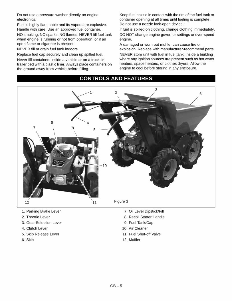
1. Parking Brake Lever
2. Throttle Lever
3. Gear Selection Lever
4. Clutch Lever
5. Skip Release Lever
6. Skip
7. Oil Level Dipstick/Fill
8. Recoil Starter Handle
9. Fuel Tank/Cap
10. Air Cleaner
11. Fuel Shut-off Valve
12. Muffler
CONTROLS AND FEATURES
Figure 3
1 2
4
5
6
89
3
7
10
1112
GB – 6
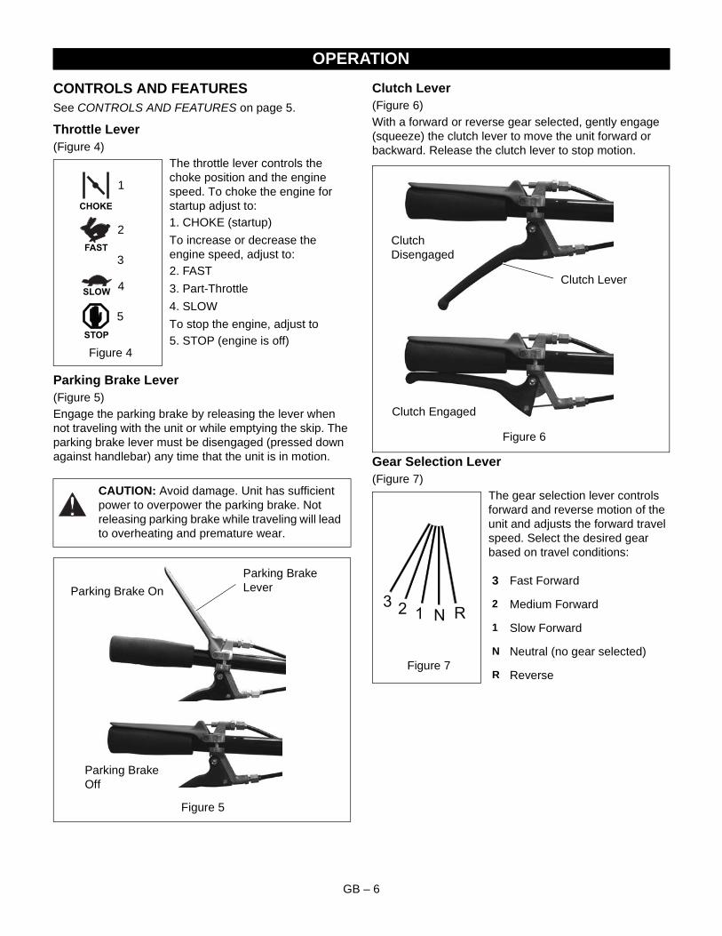
CONTROLS AND FEATURESSee CONTROLS AND FEATURES on page 5.
Throttle Lever(Figure 4)
The throttle lever controls the choke position and the engine speed. To choke the engine for startup adjust to:1. CHOKE (startup)
To increase or decrease the engine speed, adjust to:2. FAST
3. Part-Throttle
4. SLOW
To stop the engine, adjust to5. STOP (engine is off)
Parking Brake Lever(Figure 5)Engage the parking brake by releasing the lever when not traveling with the unit or while emptying the skip. The parking brake lever must be disengaged (pressed down against handlebar) any time that the unit is in motion.
Clutch Lever(Figure 6)With a forward or reverse gear selected, gently engage (squeeze) the clutch lever to move the unit forward or backward. Release the clutch lever to stop motion.
Gear Selection Lever(Figure 7)
The gear selection lever controls forward and reverse motion of the unit and adjusts the forward travel speed. Select the desired gear based on travel conditions:
OPERATION
CAUTION: Avoid damage. Unit has sufficient power to overpower the parking brake. Not releasing parking brake while traveling will lead to overheating and premature wear.
1
2
3
4
5
Figure 4
Figure 5
Parking Brake Off
Parking Brake On
Parking Brake Lever
3 Fast Forward
2 Medium Forward
1 Slow Forward
N Neutral (no gear selected)
R Reverse
Clutch Disengaged
Clutch Lever
Clutch Engaged
Figure 6
N R123
Figure 7
GB – 7
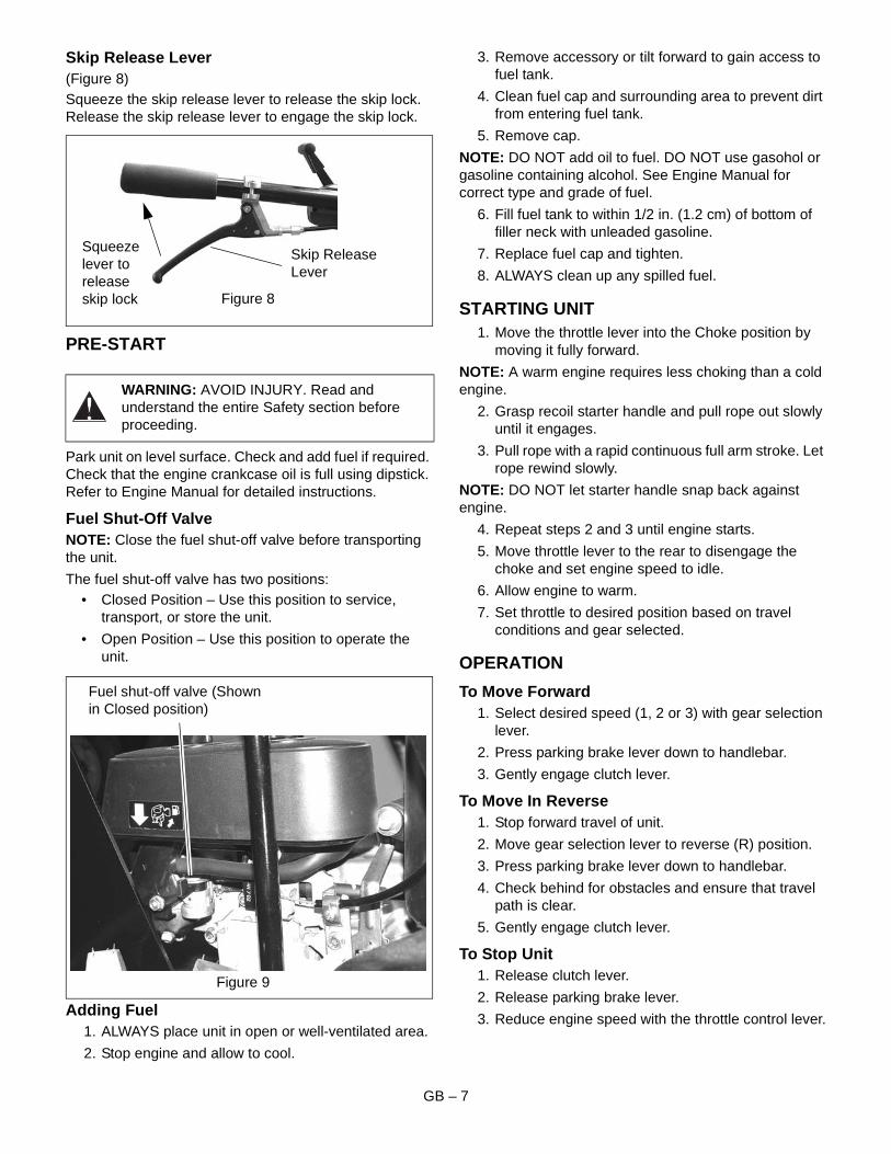
Skip Release Lever(Figure 8)Squeeze the skip release lever to release the skip lock. Release the skip release lever to engage the skip lock.
PRE-START
Park unit on level surface. Check and add fuel if required. Check that the engine crankcase oil is full using dipstick. Refer to Engine Manual for detailed instructions.
Fuel Shut-Off ValveNOTE: Close the fuel shut-off valve before transporting the unit.
The fuel shut-off valve has two positions:• Closed Position – Use this position to service,
transport, or store the unit.
• Open Position – Use this position to operate the unit.
Adding Fuel1. ALWAYS place unit in open or well-ventilated area.
2. Stop engine and allow to cool.
3. Remove accessory or tilt forward to gain access to fuel tank.
4. Clean fuel cap and surrounding area to prevent dirt from entering fuel tank.
5. Remove cap.
NOTE: DO NOT add oil to fuel. DO NOT use gasohol or gasoline containing alcohol. See Engine Manual for correct type and grade of fuel.
6. Fill fuel tank to within 1/2 in. (1.2 cm) of bottom of filler neck with unleaded gasoline.
7. Replace fuel cap and tighten.
8. ALWAYS clean up any spilled fuel.
STARTING UNIT1. Move the throttle lever into the Choke position by
moving it fully forward.
NOTE: A warm engine requires less choking than a cold engine.
2. Grasp recoil starter handle and pull rope out slowly until it engages.
3. Pull rope with a rapid continuous full arm stroke. Let rope rewind slowly.
NOTE: DO NOT let starter handle snap back against engine.
4. Repeat steps 2 and 3 until engine starts.
5. Move throttle lever to the rear to disengage the choke and set engine speed to idle.
6. Allow engine to warm.
7. Set throttle to desired position based on travel conditions and gear selected.
OPERATION
To Move Forward1. Select desired speed (1, 2 or 3) with gear selection
lever.
2. Press parking brake lever down to handlebar.
3. Gently engage clutch lever.
To Move In Reverse1. Stop forward travel of unit.
2. Move gear selection lever to reverse (R) position.
3. Press parking brake lever down to handlebar.
4. Check behind for obstacles and ensure that travel path is clear.
5. Gently engage clutch lever.
To Stop Unit1. Release clutch lever.
2. Release parking brake lever.
3. Reduce engine speed with the throttle control lever.
WARNING: AVOID INJURY. Read and understand the entire Safety section before proceeding.
Figure 8
Skip Release Lever
Squeeze lever to release skip lock
Figure 9
Fuel shut-off valve (Shown in Closed position)
GB – 8
To Empty Skip1. Stop unit and release parking brake lever.
2. Release the skip lock by squeezing the skip release lever.
3. Jerk both handlebar handles upwards. The skip will pivot forward and dump the load.
To Reset Skip1. Pull back on the skip.
2. Engage the skip lock by releasing the skip lock lever.
3. Ensure that skip lock has engaged before moving unit.
MAINTENANCE CHECK LISTPerform routine checks as outlined below. Correct any problems before using unit.
* SAE 10W-30 oil is recommended for general use. Refer to engine manual for engine maintenance procedures.
Tire Pressure1. Check tire air pressures regularly. Recommended
inflation pressure is 30 psi for all tires.
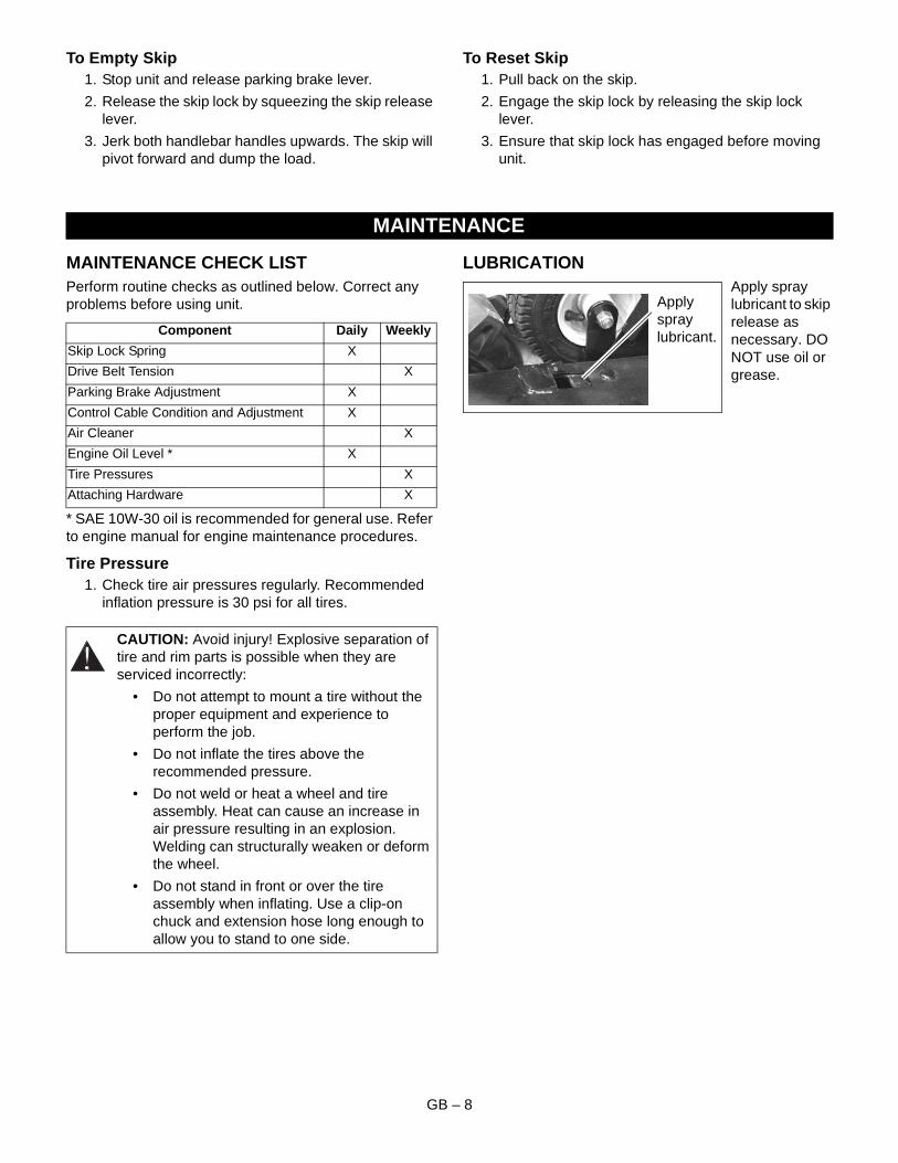
LUBRICATIONApply spray lubricant to skip release as necessary. DO NOT use oil or grease.
MAINTENANCE
Component Daily Weekly
Skip Lock Spring X
Drive Belt Tension X
Parking Brake Adjustment X
Control Cable Condition and Adjustment X
Air Cleaner X
Engine Oil Level * X
Tire Pressures X
Attaching Hardware X
CAUTION: Avoid injury! Explosive separation of tire and rim parts is possible when they are serviced incorrectly:
• Do not attempt to mount a tire without the proper equipment and experience to perform the job.
• Do not inflate the tires above the recommended pressure.
• Do not weld or heat a wheel and tire assembly. Heat can cause an increase in air pressure resulting in an explosion. Welding can structurally weaken or deform the wheel.
• Do not stand in front or over the tire assembly when inflating. Use a clip-on chuck and extension hose long enough to allow you to stand to one side.
Apply spray lubricant.
GB – 9
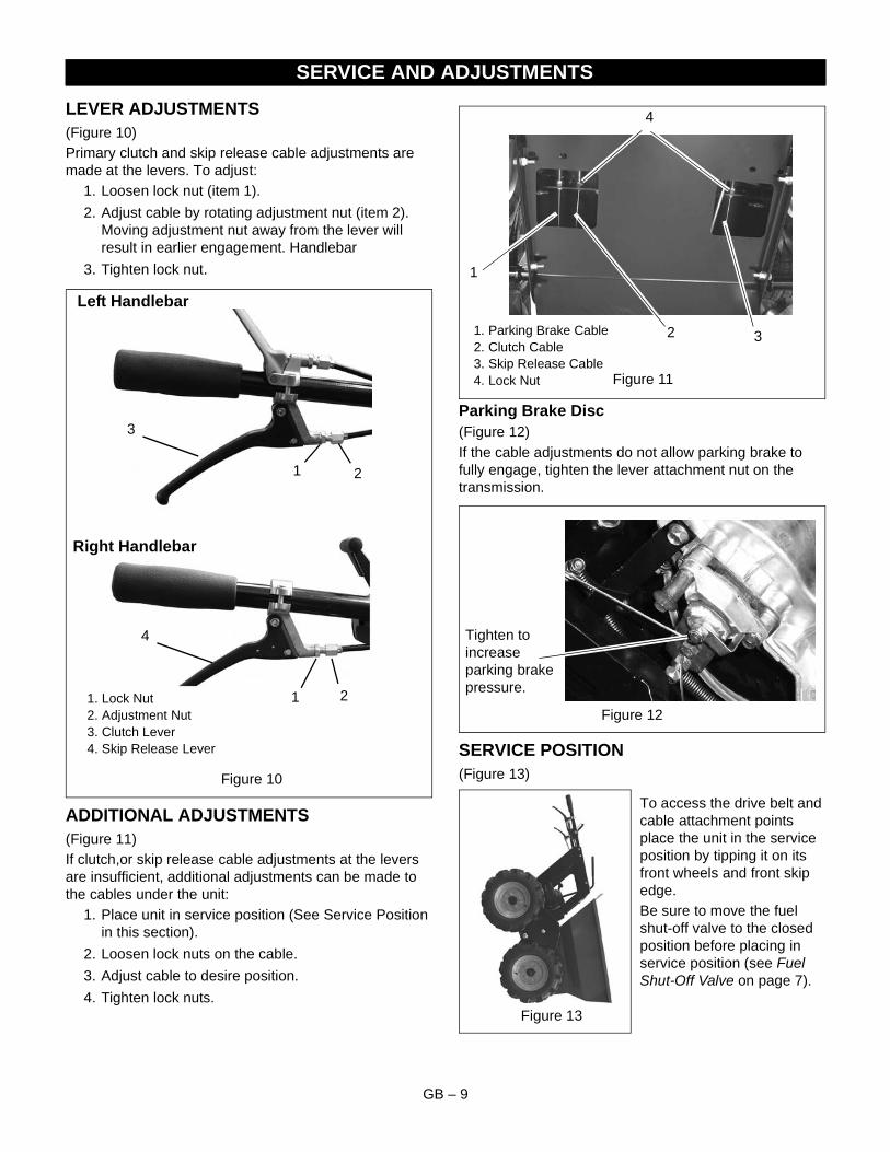
LEVER ADJUSTMENTS(Figure 10)Primary clutch and skip release cable adjustments are made at the levers. To adjust:
1. Loosen lock nut (item 1).
2. Adjust cable by rotating adjustment nut (item 2). Moving adjustment nut away from the lever will result in earlier engagement. Handlebar
3. Tighten lock nut.
ADDITIONAL ADJUSTMENTS(Figure 11)If clutch,or skip release cable adjustments at the levers are insufficient, additional adjustments can be made to the cables under the unit:
1. Place unit in service position (See Service Position in this section).
2. Loosen lock nuts on the cable.
3. Adjust cable to desire position.
4. Tighten lock nuts.
Parking Brake Disc(Figure 12)If the cable adjustments do not allow parking brake to fully engage, tighten the lever attachment nut on the transmission.
SERVICE POSITION(Figure 13)
To access the drive belt and cable attachment points place the unit in the service position by tipping it on its front wheels and front skip edge.Be sure to move the fuel shut-off valve to the closed position before placing in service position (see Fuel Shut-Off Valve on page 7).
SERVICE AND ADJUSTMENTS
Figure 10
1. Lock Nut2. Adjustment Nut3. Clutch Lever4. Skip Release Lever
1 2
1 2
4
3
Left Handlebar
Right Handlebar
Figure 11
1. Parking Brake Cable2. Clutch Cable3. Skip Release Cable4. Lock Nut
1
2 3
4
Figure 12
Tighten to increase parking brake pressure.
Figure 13
GB – 10
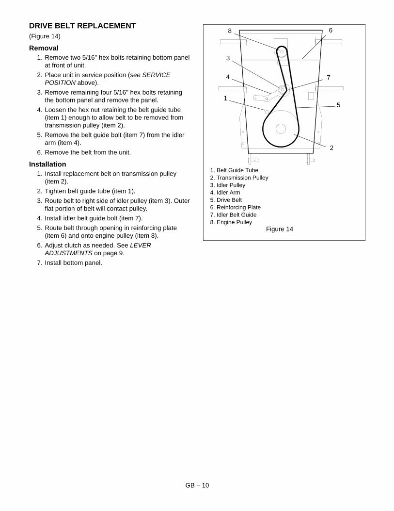
DRIVE BELT REPLACEMENT(Figure 14)
Removal1. Remove two 5/16" hex bolts retaining bottom panel
at front of unit.
2. Place unit in service position (see SERVICE POSITION above).
3. Remove remaining four 5/16" hex bolts retaining the bottom panel and remove the panel.
4. Loosen the hex nut retaining the belt guide tube (item 1) enough to allow belt to be removed from transmission pulley (item 2).
5. Remove the belt guide bolt (item 7) from the idler arm (item 4).
6. Remove the belt from the unit.
Installation1. Install replacement belt on transmission pulley
(item 2).
2. Tighten belt guide tube (item 1).
3. Route belt to right side of idler pulley (item 3). Outer flat portion of belt will contact pulley.
4. Install idler belt guide bolt (item 7).
5. Route belt through opening in reinforcing plate (item 6) and onto engine pulley (item 8).
6. Adjust clutch as needed. See LEVER ADJUSTMENTS on page 9.
7. Install bottom panel.
Figure 14
1. Belt Guide Tube2. Transmission Pulley3. Idler Pulley4. Idler Arm5. Drive Belt6. Reinforcing Plate7. Idler Belt Guide8. Engine Pulley
3
1
6
7
5
2
4
8

GB – 11
NOTES
GB – 12
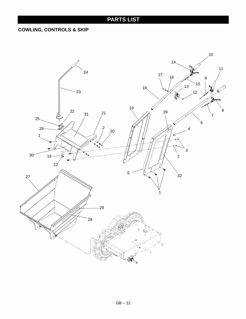
COWLING, CONTROLS & SKIP
PARTS LIST
1
11
9
87
6
5
4
3
2
12
19
1318
14
17
15
16
20
2521
24
23
26
22
27 32
28
31
30
29
10
2
12
16
1
29
GB – 13
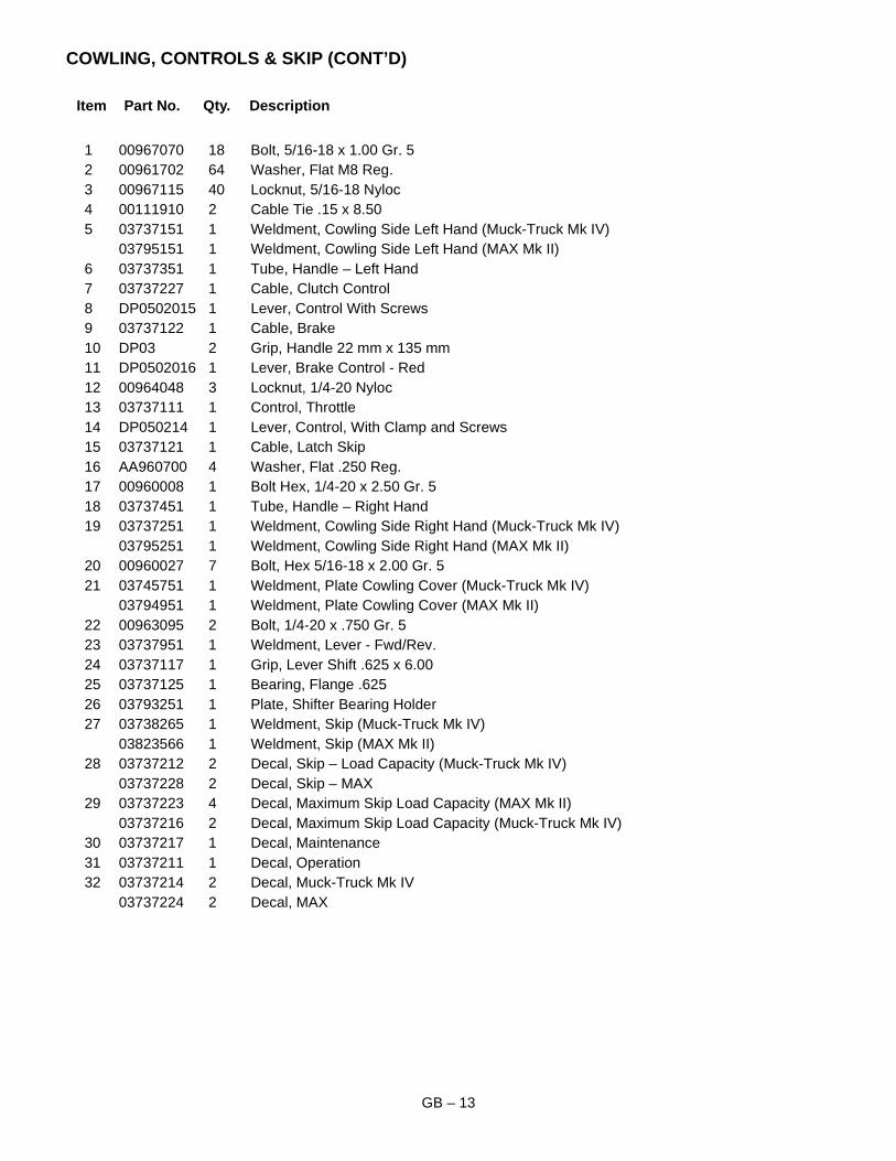
COWLING, CONTROLS & SKIP (CONT’D)
Item Part No. Qty. Description
1 00967070 18 Bolt, 5/16-18 x 1.00 Gr. 52 00961702 64 Washer, Flat M8 Reg.3 00967115 40 Locknut, 5/16-18 Nyloc4 00111910 2 Cable Tie .15 x 8.505 03737151 1 Weldment, Cowling Side Left Hand (Muck-Truck Mk IV)
03795151 1 Weldment, Cowling Side Left Hand (MAX Mk II)6 03737351 1 Tube, Handle – Left Hand7 03737227 1 Cable, Clutch Control8 DP0502015 1 Lever, Control With Screws9 03737122 1 Cable, Brake10 DP03 2 Grip, Handle 22 mm x 135 mm11 DP0502016 1 Lever, Brake Control - Red12 00964048 3 Locknut, 1/4-20 Nyloc13 03737111 1 Control, Throttle14 DP050214 1 Lever, Control, With Clamp and Screws15 03737121 1 Cable, Latch Skip16 AA960700 4 Washer, Flat .250 Reg.17 00960008 1 Bolt Hex, 1/4-20 x 2.50 Gr. 518 03737451 1 Tube, Handle – Right Hand19 03737251 1 Weldment, Cowling Side Right Hand (Muck-Truck Mk IV)
03795251 1 Weldment, Cowling Side Right Hand (MAX Mk II)20 00960027 7 Bolt, Hex 5/16-18 x 2.00 Gr. 521 03745751 1 Weldment, Plate Cowling Cover (Muck-Truck Mk IV)
03794951 1 Weldment, Plate Cowling Cover (MAX Mk II)22 00963095 2 Bolt, 1/4-20 x .750 Gr. 523 03737951 1 Weldment, Lever - Fwd/Rev.24 03737117 1 Grip, Lever Shift .625 x 6.0025 03737125 1 Bearing, Flange .62526 03793251 1 Plate, Shifter Bearing Holder27 03738265 1 Weldment, Skip (Muck-Truck Mk IV)
03823566 1 Weldment, Skip (MAX Mk II)28 03737212 2 Decal, Skip – Load Capacity (Muck-Truck Mk IV)
03737228 2 Decal, Skip – MAX29 03737223 4 Decal, Maximum Skip Load Capacity (MAX Mk II)
03737216 2 Decal, Maximum Skip Load Capacity (Muck-Truck Mk IV)30 03737217 1 Decal, Maintenance31 03737211 1 Decal, Operation32 03737214 2 Decal, Muck-Truck Mk IV
03737224 2 Decal, MAX
GB – 14
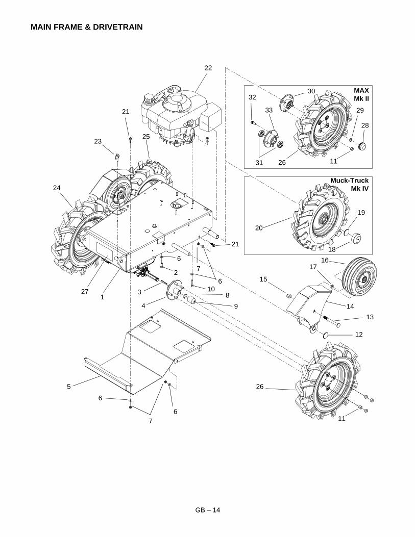
MAIN FRAME & DRIVETRAIN
1
2
Muck-TruckMk IV
MAXMk II
83
7
4
5
6
9
15
14
10
11
12
13
16
30
21
17
18
19
26
29
28
27
26
25
24
23
22
31
33
32
20
6
6
6
7
21
11
GB – 15
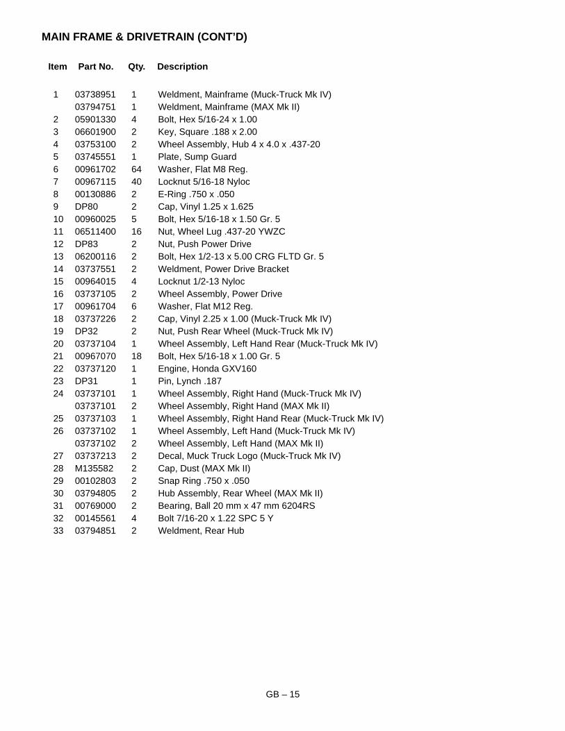
MAIN FRAME & DRIVETRAIN (CONT’D)
Item Part No. Qty. Description
1 03738951 1 Weldment, Mainframe (Muck-Truck Mk IV)03794751 1 Weldment, Mainframe (MAX Mk II)
2 05901330 4 Bolt, Hex 5/16-24 x 1.003 06601900 2 Key, Square .188 x 2.004 03753100 2 Wheel Assembly, Hub 4 x 4.0 x .437-205 03745551 1 Plate, Sump Guard6 00961702 64 Washer, Flat M8 Reg.7 00967115 40 Locknut 5/16-18 Nyloc8 00130886 2 E-Ring .750 x .0509 DP80 2 Cap, Vinyl 1.25 x 1.62510 00960025 5 Bolt, Hex 5/16-18 x 1.50 Gr. 511 06511400 16 Nut, Wheel Lug .437-20 YWZC12 DP83 2 Nut, Push Power Drive13 06200116 2 Bolt, Hex 1/2-13 x 5.00 CRG FLTD Gr. 514 03737551 2 Weldment, Power Drive Bracket15 00964015 4 Locknut 1/2-13 Nyloc16 03737105 2 Wheel Assembly, Power Drive17 00961704 6 Washer, Flat M12 Reg.18 03737226 2 Cap, Vinyl 2.25 x 1.00 (Muck-Truck Mk IV)19 DP32 2 Nut, Push Rear Wheel (Muck-Truck Mk IV)20 03737104 1 Wheel Assembly, Left Hand Rear (Muck-Truck Mk IV)21 00967070 18 Bolt, Hex 5/16-18 x 1.00 Gr. 522 03737120 1 Engine, Honda GXV16023 DP31 1 Pin, Lynch .18724 03737101 1 Wheel Assembly, Right Hand (Muck-Truck Mk IV)
03737101 2 Wheel Assembly, Right Hand (MAX Mk II)25 03737103 1 Wheel Assembly, Right Hand Rear (Muck-Truck Mk IV)26 03737102 1 Wheel Assembly, Left Hand (Muck-Truck Mk IV)
03737102 2 Wheel Assembly, Left Hand (MAX Mk II)27 03737213 2 Decal, Muck Truck Logo (Muck-Truck Mk IV)28 M135582 2 Cap, Dust (MAX Mk II)29 00102803 2 Snap Ring .750 x .05030 03794805 2 Hub Assembly, Rear Wheel (MAX Mk II)31 00769000 2 Bearing, Ball 20 mm x 47 mm 6204RS32 00145561 4 Bolt 7/16-20 x 1.22 SPC 5 Y33 03794851 2 Weldment, Rear Hub

GB – 16
TRANSMISSION AND BELT DRIVE
1
23
11
10
9
4
5
6
78
12
1817
13
14
15
16
25
19
20
21
22
23
24
31
32
26
27
28
29
30
39
33
38
34
35
36
37
4
4
4
34
4140
10
10
23
13
323
13
144
3
4
4
3
4
3
4
26
27
34
2028
6
Muck-Truck Mk IV:12.497"(31.74 cm)
MAX:12.425"
GB – 17
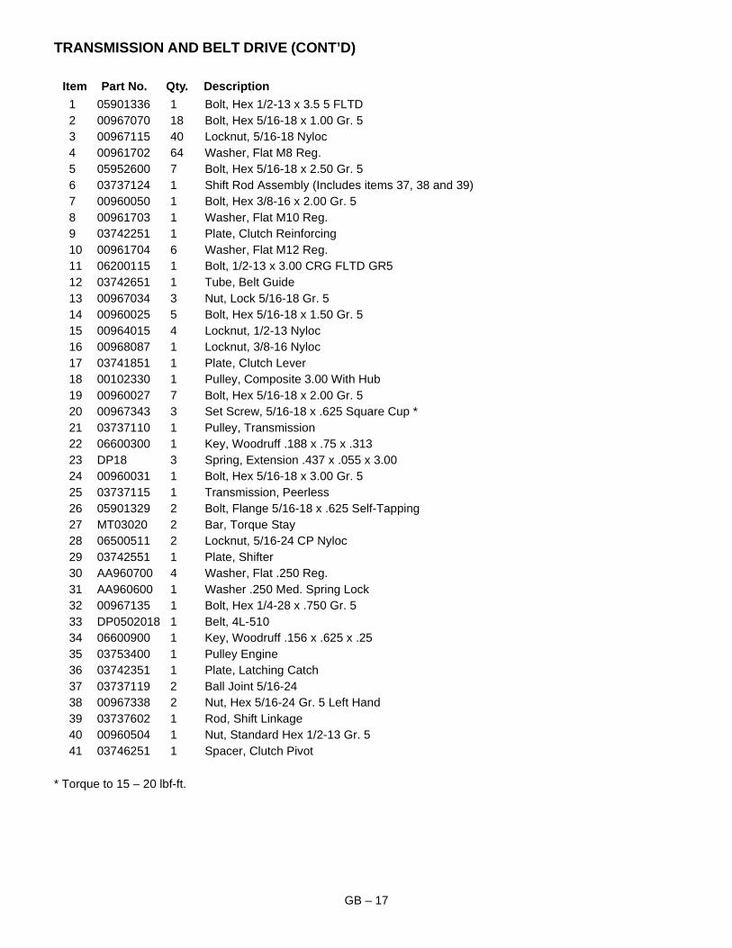
TRANSMISSION AND BELT DRIVE (CONT’D)
Item Part No. Qty. Description
1 05901336 1 Bolt, Hex 1/2-13 x 3.5 5 FLTD2 00967070 18 Bolt, Hex 5/16-18 x 1.00 Gr. 53 00967115 40 Locknut, 5/16-18 Nyloc4 00961702 64 Washer, Flat M8 Reg.5 05952600 7 Bolt, Hex 5/16-18 x 2.50 Gr. 56 03737124 1 Shift Rod Assembly (Includes items 37, 38 and 39)7 00960050 1 Bolt, Hex 3/8-16 x 2.00 Gr. 58 00961703 1 Washer, Flat M10 Reg.9 03742251 1 Plate, Clutch Reinforcing10 00961704 6 Washer, Flat M12 Reg.11 06200115 1 Bolt, 1/2-13 x 3.00 CRG FLTD GR512 03742651 1 Tube, Belt Guide13 00967034 3 Nut, Lock 5/16-18 Gr. 514 00960025 5 Bolt, Hex 5/16-18 x 1.50 Gr. 515 00964015 4 Locknut, 1/2-13 Nyloc16 00968087 1 Locknut, 3/8-16 Nyloc17 03741851 1 Plate, Clutch Lever18 00102330 1 Pulley, Composite 3.00 With Hub19 00960027 7 Bolt, Hex 5/16-18 x 2.00 Gr. 520 00967343 3 Set Screw, 5/16-18 x .625 Square Cup *21 03737110 1 Pulley, Transmission22 06600300 1 Key, Woodruff .188 x .75 x .31323 DP18 3 Spring, Extension .437 x .055 x 3.0024 00960031 1 Bolt, Hex 5/16-18 x 3.00 Gr. 525 03737115 1 Transmission, Peerless26 05901329 2 Bolt, Flange 5/16-18 x .625 Self-Tapping27 MT03020 2 Bar, Torque Stay28 06500511 2 Locknut, 5/16-24 CP Nyloc29 03742551 1 Plate, Shifter30 AA960700 4 Washer, Flat .250 Reg.31 AA960600 1 Washer .250 Med. Spring Lock32 00967135 1 Bolt, Hex 1/4-28 x .750 Gr. 533 DP0502018 1 Belt, 4L-51034 06600900 1 Key, Woodruff .156 x .625 x .2535 03753400 1 Pulley Engine36 03742351 1 Plate, Latching Catch37 03737119 2 Ball Joint 5/16-2438 00967338 2 Nut, Hex 5/16-24 Gr. 5 Left Hand39 03737602 1 Rod, Shift Linkage40 00960504 1 Nut, Standard Hex 1/2-13 Gr. 541 03746251 1 Spacer, Clutch Pivot
* Torque to 15 – 20 lbf-ft.
GB – 18
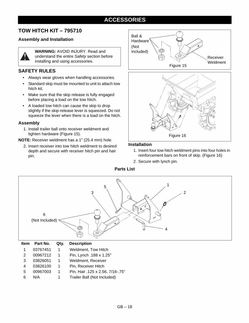
TOW HITCH KIT – 795710
Assembly and Installation
SAFETY RULES• Always wear gloves when handling accessories.
• Standard skip must be mounted to unit to attach tow hitch kit.
• Make sure that the skip release is fully engaged before placing a load on the tow hitch.
• A loaded tow hitch can cause the skip to drop slightly if the skip-release lever is squeezed. Do not squeeze the lever when there is a load on the hitch.
Assembly1. Install trailer ball onto receiver weldment and
tighten hardware (Figure 15).
NOTE: Receiver weldment has a 1" (25.4 mm) hole.
2. Insert receiver into tow hitch weldment to desired depth and secure with receiver hitch pin and hair pin.
Installation1. Insert four tow hitch weldment pins into four holes in
reinforcement bars on front of skip. (Figure 16)
2. Secure with lynch pin.
Parts List
Item Part No. Qty. Description
1 03767451 1 Weldment, Tow Hitch2 00967212 1 Pin, Lynch .188 x 1.25"3 03826051 1 Weldment, Receiver4 03826100 1 Pin, Receiver Hitch5 00967003 1 Pin, Hair .125 x 2.56, 7/16-.75"6 N/A 1 Trailer Ball (Not Included)
ACCESSORIES
WARNING: AVOID INJURY. Read and understand the entire Safety section before installing and using accessories.
Figure 15
Receiver Weldment
Ball & Hardware(Not Included)
Figure 16
1
23
5
4
6(Not Included)
GB – 19
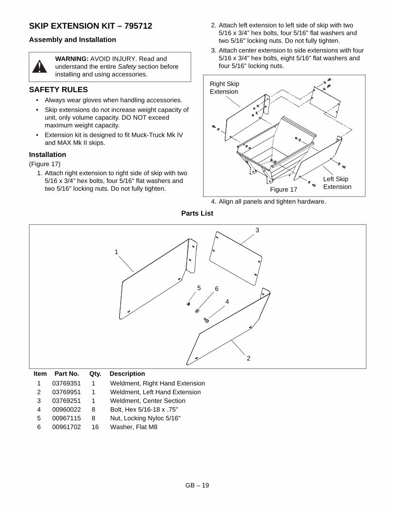
SKIP EXTENSION KIT – 795712
Assembly and Installation
SAFETY RULES• Always wear gloves when handling accessories.
• Skip extensions do not increase weight capacity of unit, only volume capacity. DO NOT exceed maximum weight capacity.
• Extension kit is designed to fit Muck-Truck Mk IV and MAX Mk II skips.
Installation(Figure 17)
1. Attach right extension to right side of skip with two 5/16 x 3/4" hex bolts, four 5/16" flat washers and two 5/16" locking nuts. Do not fully tighten.
2. Attach left extension to left side of skip with two 5/16 x 3/4" hex bolts, four 5/16" flat washers and two 5/16" locking nuts. Do not fully tighten.
3. Attach center extension to side extensions with four 5/16 x 3/4" hex bolts, eight 5/16" flat washers and four 5/16" locking nuts.
4. Align all panels and tighten hardware.
Parts List
Item Part No. Qty. Description
1 03769351 1 Weldment, Right Hand Extension2 03769951 1 Weldment, Left Hand Extension3 03769251 1 Weldment, Center Section4 00960022 8 Bolt, Hex 5/16-18 x .75"5 00967115 8 Nut, Locking Nyloc 5/16"6 00961702 16 Washer, Flat M8
WARNING: AVOID INJURY. Read and understand the entire Safety section before installing and using accessories.
Figure 17
Right Skip Extension
Left Skip Extension
1
2
3
4
5 6
GB – 20
WHEEL EXTENSION KIT – 795713
Assembly and Installation
SAFETY RULES• Always wear gloves when handling accessories.
• Remove load from unit before installing wheel extension kit.
• Install wheel extension kit on front wheels.
• If inner wheel is removed during installation it will be necessary to deflate the tires to reinstall.
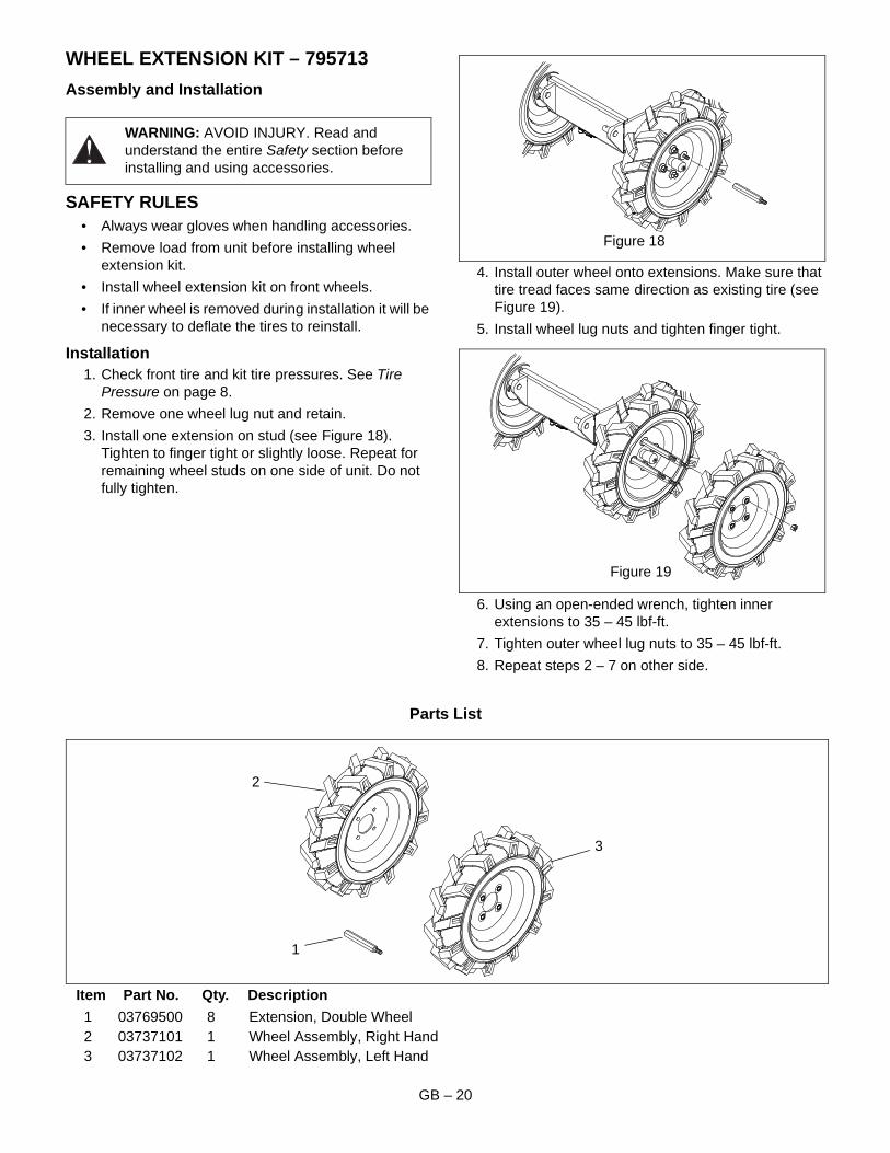
Installation1. Check front tire and kit tire pressures. See Tire
Pressure on page 8.
2. Remove one wheel lug nut and retain.
3. Install one extension on stud (see Figure 18). Tighten to finger tight or slightly loose. Repeat for remaining wheel studs on one side of unit. Do not fully tighten.
4. Install outer wheel onto extensions. Make sure that tire tread faces same direction as existing tire (see Figure 19).
5. Install wheel lug nuts and tighten finger tight.
6. Using an open-ended wrench, tighten inner extensions to 35 – 45 lbf-ft.
7. Tighten outer wheel lug nuts to 35 – 45 lbf-ft.
8. Repeat steps 2 – 7 on other side.
Parts List
Item Part No. Qty. Description
1 03769500 8 Extension, Double Wheel2 03737101 1 Wheel Assembly, Right Hand3 03737102 1 Wheel Assembly, Left Hand
WARNING: AVOID INJURY. Read and understand the entire Safety section before installing and using accessories.
Figure 18
Figure 19
1
2
3

GB – 21
NOTES
GB – 22
SNOW PLOW KIT – 795714
Assembly and Installation
SAFETY RULES• Always wear gloves when handling accessories.
• The weight of the snow plow can cause the skip to drop slightly against the lock plate if the skip-release lever is squeezed. Do not squeeze the lever with snow plow attached.
• Use caution when releasing snow plow from transport position and when lowering to surface.
• It may be necessary to obtain assistance with assembly and installation.
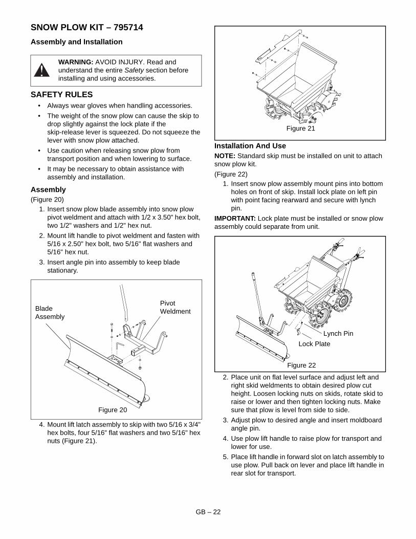
Assembly(Figure 20)
1. Insert snow plow blade assembly into snow plow pivot weldment and attach with 1/2 x 3.50" hex bolt, two 1/2" washers and 1/2" hex nut.
2. Mount lift handle to pivot weldment and fasten with 5/16 x 2.50" hex bolt, two 5/16" flat washers and 5/16" hex nut.
3. Insert angle pin into assembly to keep blade stationary.
4. Mount lift latch assembly to skip with two 5/16 x 3/4" hex bolts, four 5/16" flat washers and two 5/16" hex nuts (Figure 21).
Installation And UseNOTE: Standard skip must be installed on unit to attach snow plow kit.
(Figure 22)1. Insert snow plow assembly mount pins into bottom
holes on front of skip. Install lock plate on left pin with point facing rearward and secure with lynch pin.
IMPORTANT: Lock plate must be installed or snow plow assembly could separate from unit.
2. Place unit on flat level surface and adjust left and right skid weldments to obtain desired plow cut height. Loosen locking nuts on skids, rotate skid to raise or lower and then tighten locking nuts. Make sure that plow is level from side to side.
3. Adjust plow to desired angle and insert moldboard angle pin.
4. Use plow lift handle to raise plow for transport and lower for use.
5. Place lift handle in forward slot on latch assembly to use plow. Pull back on lever and place lift handle in rear slot for transport.
WARNING: AVOID INJURY. Read and understand the entire Safety section before installing and using accessories.
Figure 20
Blade Assembly
Pivot Weldment
Figure 21
Figure 22
Lock Plate
Lynch Pin
GB – 23
SNOW PLOW KIT – 795714 (CONT’D)
Parts List
Item Part No. Qty. Description
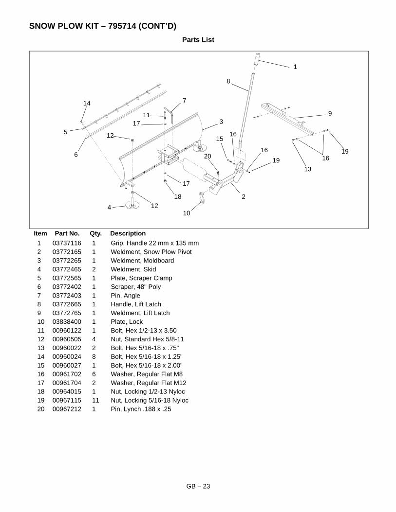
1 03737116 1 Grip, Handle 22 mm x 135 mm2 03772165 1 Weldment, Snow Plow Pivot3 03772265 1 Weldment, Moldboard4 03772465 2 Weldment, Skid5 03772565 1 Plate, Scraper Clamp6 03772402 1 Scraper, 48" Poly7 03772403 1 Pin, Angle8 03772665 1 Handle, Lift Latch9 03772765 1 Weldment, Lift Latch10 03838400 1 Plate, Lock11 00960122 1 Bolt, Hex 1/2-13 x 3.5012 00960505 4 Nut, Standard Hex 5/8-1113 00960022 2 Bolt, Hex 5/16-18 x .75"14 00960024 8 Bolt, Hex 5/16-18 x 1.25"15 00960027 1 Bolt, Hex 5/16-18 x 2.00"16 00961702 6 Washer, Regular Flat M817 00961704 2 Washer, Regular Flat M1218 00964015 1 Nut, Locking 1/2-13 Nyloc19 00967115 11 Nut, Locking 5/16-18 Nyloc20 00967212 1 Pin, Lynch .188 x .25
1
2
3
4
5
6
8
7
9
10
11
12
13
14
15
1619
17
1812
17
2019
16
16
GB – 24
RAMP KIT – 795715
Assembly and Installation
SAFETY RULES• Always wear gloves when handling ramp
components.
• Approximate ramp weights are 77 lb. (35 kg) for the upper section and 44 lb. (20 kg) for the lower section. It may be necessary to obtain assistance with handling, assembly and disassembly.
• Erect ramp on a flat, level surface.
• Ensure that the ramp is used in a safe manner.
• Keep area around ramp free of debris.
• Ramp capacity is 992 lb. (450 kg) DO NOT overload.
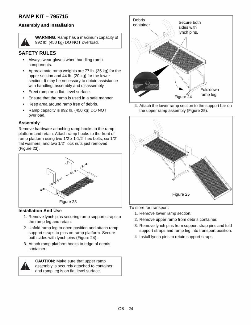
AssemblyRemove hardware attaching ramp hooks to the ramp platform and retain. Attach ramp hooks to the front of ramp platform using two 1/2 x 1-1/2" hex bolts, six 1/2" flat washers, and two 1/2" lock nuts just removed (Figure 23).
Installation And Use1. Remove lynch pins securing ramp support straps to
the ramp leg and retain.
2. Unfold ramp leg to open position and attach ramp support straps to pins on ramp platform. Secure both sides with lynch pins (Figure 24).
3. Attach ramp platform hooks to edge of debris container.
4. Attach the lower ramp section to the support bar on the upper ramp assembly (Figure 25).
To store for transport:1. Remove lower ramp section.
2. Remove upper ramp from debris container.
3. Remove lynch pins from support strap pins and fold support straps and ramp leg into transport position.
4. Install lynch pins to retain support straps.
WARNING: Ramp has a maximum capacity of 992 lb. (450 kg) DO NOT overload.
CAUTION: Make sure that upper ramp assembly is securely attached to container and ramp leg is on flat level surface.
Figure 23
Fold down ramp leg.
Debris container
Secure both sides with lynch pins.
Figure 24
Figure 25
GB – 25
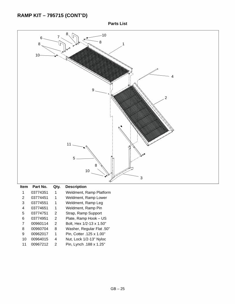
RAMP KIT – 795715 (CONT’D)
Parts List
Item Part No. Qty. Description
1 03774351 1 Weldment, Ramp Platform2 03774451 1 Weldment, Ramp Lower3 03774551 1 Weldment, Ramp Leg4 03774651 1 Weldment, Ramp Pin5 03774751 2 Strap, Ramp Support6 03774951 2 Plate, Ramp Hook – US7 00960114 2 Bolt, Hex 1/2-13 x 1.50"8 00960704 8 Washer, Regular Flat .50"9 00962017 1 Pin, Cotter .125 x 1.00"10 00964015 4 Nut, Lock 1/2-13" Nyloc11 00967212 2 Pin, Lynch .188 x 1.25"
1
2
3
4
9
10
11
5
6 78
8
108
8
10
GB – 26
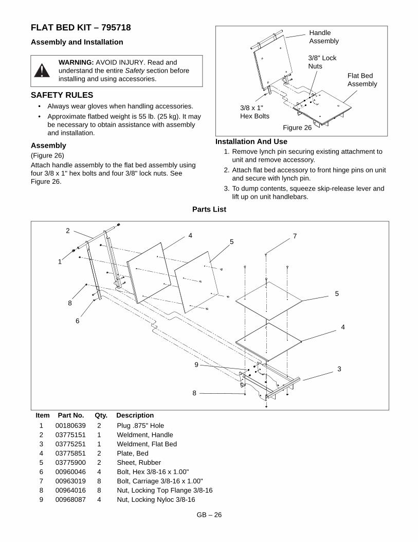
FLAT BED KIT – 795718
Assembly and Installation
SAFETY RULES• Always wear gloves when handling accessories.
• Approximate flatbed weight is 55 lb. (25 kg). It may be necessary to obtain assistance with assembly and installation.
Assembly(Figure 26)Attach handle assembly to the flat bed assembly using four 3/8 x 1" hex bolts and four 3/8" lock nuts. See Figure 26.
Installation And Use1. Remove lynch pin securing existing attachment to
unit and remove accessory.
2. Attach flat bed accessory to front hinge pins on unit and secure with lynch pin.
3. To dump contents, squeeze skip-release lever and lift up on unit handlebars.
Parts List
Item Part No. Qty. Description
1 00180639 2 Plug .875" Hole2 03775151 1 Weldment, Handle3 03775251 1 Weldment, Flat Bed4 03775851 2 Plate, Bed5 03775900 2 Sheet, Rubber6 00960046 4 Bolt, Hex 3/8-16 x 1.00"7 00963019 8 Bolt, Carriage 3/8-16 x 1.00"8 00964016 8 Nut, Locking Top Flange 3/8-169 00968087 4 Nut, Locking Nyloc 3/8-16
WARNING: AVOID INJURY. Read and understand the entire Safety section before installing and using accessories.
Figure 26
Handle Assembly
Flat Bed Assembly
3/8 x 1" Hex Bolts
3/8" Lock Nuts
1
2
4
5
6
7
8
93
54
8
GB – 27
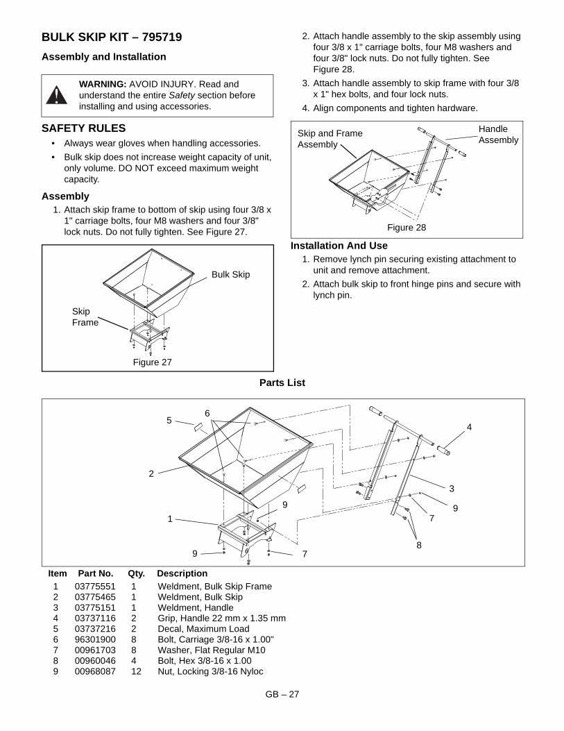
BULK SKIP KIT – 795719
Assembly and Installation
SAFETY RULES• Always wear gloves when handling accessories.
• Bulk skip does not increase weight capacity of unit, only volume. DO NOT exceed maximum weight capacity.
Assembly1. Attach skip frame to bottom of skip using four 3/8 x
1" carriage bolts, four M8 washers and four 3/8" lock nuts. Do not fully tighten. See Figure 27.
2. Attach handle assembly to the skip assembly using four 3/8 x 1" carriage bolts, four M8 washers and four 3/8" lock nuts. Do not fully tighten. See Figure 28.
3. Attach handle assembly to skip frame with four 3/8 x 1" hex bolts, and four lock nuts.
4. Align components and tighten hardware.
Installation And Use1. Remove lynch pin securing existing attachment to
unit and remove attachment.
2. Attach bulk skip to front hinge pins and secure with lynch pin.
Parts List
Item Part No. Qty. Description1 03775551 1 Weldment, Bulk Skip Frame2 03775465 1 Weldment, Bulk Skip3 03775151 1 Weldment, Handle4 03737116 2 Grip, Handle 22 mm x 1.35 mm5 03737216 2 Decal, Maximum Load6 96301900 8 Bolt, Carriage 3/8-16 x 1.00"7 00961703 8 Washer, Flat Regular M108 00960046 4 Bolt, Hex 3/8-16 x 1.009 00968087 12 Nut, Locking 3/8-16 Nyloc
WARNING: AVOID INJURY. Read and understand the entire Safety section before installing and using accessories.
Figure 27
Skip Frame
Bulk Skip
Figure 28
Skip and Frame Assembly
Handle Assembly
1
2
54
3
6
8
99
9 7
7
GB – 28
Serial Number:
Warranty is 12 calendar months from date of sale for Consumers and 90 days for units used in the Commercial Sector.Under the following conditions:
• Routine maintenance completed in accordance with Owners Manual.
• Returned defective parts are approved by Niche Product Sales LLC.
• Machine is not abused or operated with known faults or lack of maintenance.
• Repairs are in accordance with Niche Product Sales LLC.
AT AN AGREED JOB RATEOnly defective parts are covered, and not wearable components which require replacement because of normal wear, for example puncture, chipped paint, dented skip etc. Niche Product Sales LLC will not be held liable for anyconsequential losses.
PERSONAL CUSTOMER GUARANTEE STATEMENTIf there is any component, or components, manufactured by Niche Product Sales LLC Ltd. which are found to be defective within 12 months from the date of purchase (or 90 days in the case of a machine used for hire/commercialpurposes), Niche Product Sales LLC. will replace the faulty component(s) free of charge, provided they are notified immediately upon date of failure.
THE FOLLOWING ARE NOT COVERED BY THIS GUARANTEE1. Engines – Engines are guaranteed by their respective manufacturers.
2. A machine which has been subject to operation in excess of recommended capacities, misuse, negligence or accident, or has been altered or modified in a manner which has not been authorized by Niche Product Sales LLC.
3. Wear parts – belts, cables etc.
4. Transportation Charge – to and from the warranty repair site.
Niche Product Sales LLC operates a policy of continual development and reserves the right to alter product specifications without giving prior notice.
WARRANTY


Niche Product Sales LLC586 Mercantile PlacePort Saint Lucie, FL 34986www.mucktruck.com