mti marker - intersoft electronicsintersoft-electronics.com/downloads/usermanuals... · mti marker...
TRANSCRIPT

MTI Marker
User Manual
Edition: 5Date: 27-Sep-16Status: Released Issue

MTI Marker Edition Date: 27-Sep-16
DOCUMENT CHARACTERISTICS
General
MTI Marker
User Manual
Edition: 5
Edition Date: 27-September-2016
Status: Released Issue
Keywords: MTI Marker; STG882; Static Target; RTG1002
Abstract: This user manual explains how to work with the MTI Marker (STG882 + antenna). It provides information on the hardware components and instructions on how to use the MTI Setup Assistant in the RASS-S toolbox. Also an introductory section to the RTG1002 is appended.
Contact Information
Author: Elke Vanuytven
Editor: Elke Vanuytven
Contact Person: IE Support Department
Tel: +32 14 23 18 11
E-mail Address: [email protected]
Document Control Information
Document Name: IE-UM-00282-005 MTI Marker.odt
Path: C:\Users\elke\Desktop\
Host System: Windows XP SP2
Software: OpenOffice.org 3.0.1
Size: 5.29 MB
IE-UM-00282-005 MTI Marker.odt 2/19
MTI Marker Edition Date: 27-Sep-16
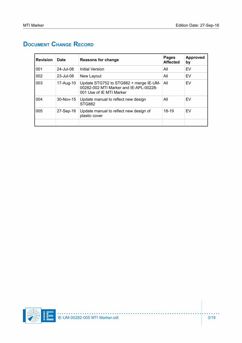
DOCUMENT CHANGE RECORD
Revision Date Reasons for changePages Affected
Approved by
001 24-Jul-08 Initial Version All EV
002 23-Jul-08 New Layout All EV
003 17-Aug-10 Update STG752 to STG882 + merge IE-UM-00282-002 MTI Marker and IE-APL-00228-001 Use of IE MTI Marker
All EV
004 30-Nov-15 Update manual to reflect new design STG882
All EV
005 27-Sep-16 Update manual to reflect new design of plastic cover
18-19 EV
IE-UM-00282-005 MTI Marker.odt 3/19

MTI Marker Edition Date: 27-Sep-16
TABLE OF CONTENTS
1. INTRODUCTION ............................................................................................................. 8
2. MODULAR SET-UP ....................................................................................................... 8
2.1. Stationary Target Generator (STG882) .............................................................................................. 8
2.2. Antenna .............................................................................................................................................. 11
2.3. Field Set-up ....................................................................................................................................... 11
3. THE MTI SETUP ASSISTANT ........................................................................................ 13
4. UTILIZATION INSTRUCTIONS ........................................................................................... 16
4.1. Verification of the Phase Flipping Rate ........................................................................................... 16
4.2. Verification of the Power Levels and Matching with Uplink Measurement .................................. 16
5. MTI MARKER WITH OPTIONAL TEST FLIGHT SIMULATION ................................................... 17
6. APPENDIX: INSTALLING STG882 INTO PLASTIC COVER .................................................... 18
IE-UM-00282-005 MTI Marker.odt 4/19

MTI Marker Edition Date: 27-Sep-16
TABLE OF FIGURES
Figure 1: Stationary Target Generator STG882 ............................................................................................ 8Figure 2: Schematic Overview of STG882 .................................................................................................... 9Figure 3: Picture of the STG882 .................................................................................................................. 10Figure 4: Specifications of STG882 ............................................................................................................ 10Figure 5: Clutter map example in RASS-S software .................................................................................. 12Figure 6: PSR Target Generation section with MTI Marker button ........................................................... 13Figure 7: MTI Setup Assistant ..................................................................................................................... 13Figure 8: Calculate distances RTG window ............................................................................................... 15Figure 9: Radar Target Generator RTG1002 ............................................................................................... 17Figure 10: Step 1 ........................................................................................................................................... 18Figure 11: Step 2 ........................................................................................................................................... 18Figure 12: Step 3 ........................................................................................................................................... 19Figure 13: Step 4 ........................................................................................................................................... 19
CONVENTIONS USED
Note: This icon to the left of bold italicized text denotes a note, which alerts you to important information.
Caution: This icon to the left of bold italicized text denotes a caution, which alerts you to thepossibility of data loss or a system crash.
Warning: This icon to the left of bold italicized text denotes a warning, which alerts you to the possibility of damage to you or your equipment.
IE-UM-00282-005 MTI Marker.odt 5/19
G
%
M

MTI Marker Edition Date: 27-Sep-16
GLOSSARY OF TERMS
ACP Azimuth Change PulseADS-B Automatic Dependent Surveillance, BroadcastAnnex 10 Aeronautical Telecommunication, Annex 10 to the Convention on
International Civil Aviation, the principle international document defining SSR
ARP Azimuth Reference PulseASTERIX All Purpose Structured Eurocontrol Surveillance Information
Exchange, is the standard protocol for ATC dataATC Air Traffic ControlCOTS Commercial Off The ShelfCPU Computer Processing UnitCW Continuous wavedB DecibelDownlink The signal path from aircraft to groundFL Flight Level, unit of altitude (expressed in 100’s of feet)FRUIT False Replies Unsynchronized In Time, unwanted SSR replies
received by an interrogator which have been triggered by other interrogators
GPS Global Positioning SystemICAO International Civil Aviation OrganizationICD Interface Control DocumentIE Intersoft ElectronicsIF Intermediate FrequencyI/O Input/OutputIP Internet ProtocolLAN Local Area NetworkLVA Large Vertical Aperture (antenna)Monopulse Radar-receiving processing technique used to provide a precise
bearing measurementMOS Metal Oxide SemiconductorMSSR Monopulse Secondary Surveillance RadarMTD Moving Target DetectionMTI Moving Target IndicatorMultipath Interference and distortion effects due to the presence of more
than one path between transmitter and receiverNM Nautical Mile, unit of distance OEM Original Equipment ManufacturerPIN diode PN diode with Insulating layer between P and N layersPlot extractor Signal-processing equipment which converts receiver video into
digital target reports suitable for transmission by land linesPPI Plan Position IndicatorPRF Pulse Repetition FrequencyPSR Primary Surveillance RadarRadar Radio Detection And RangingRadome Radio-transparent window used to protect an antenna principally
against the effects of weatherRASS-R Radar Analysis Support Systems – Real-time measurementsRASS-S Radar Analysis Support Systems – Site measurementsRCS Radar Cross SectionRDP Radar Data Processing (system)RES Radar Environment Simulator
IE-UM-00282-005 MTI Marker.odt 6/19
MTI Marker Edition Date: 27-Sep-16
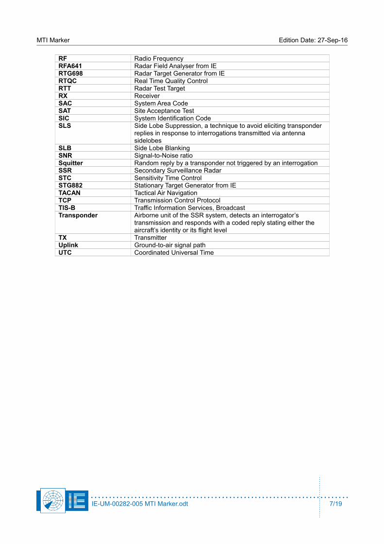
RF Radio FrequencyRFA641 Radar Field Analyser from IERTG698 Radar Target Generator from IERTQC Real Time Quality ControlRTT Radar Test TargetRX ReceiverSAC System Area CodeSAT Site Acceptance TestSIC System Identification CodeSLS Side Lobe Suppression, a technique to avoid eliciting transponder
replies in response to interrogations transmitted via antenna sidelobes
SLB Side Lobe BlankingSNR Signal-to-Noise ratioSquitter Random reply by a transponder not triggered by an interrogationSSR Secondary Surveillance RadarSTC Sensitivity Time ControlSTG882 Stationary Target Generator from IETACAN Tactical Air NavigationTCP Transmission Control ProtocolTIS-B Traffic Information Services, BroadcastTransponder Airborne unit of the SSR system, detects an interrogator’s
transmission and responds with a coded reply stating either the aircraft’s identity or its flight level
TX TransmitterUplink Ground-to-air signal pathUTC Coordinated Universal Time
IE-UM-00282-005 MTI Marker.odt 7/19

MTI Marker Edition Date: 27-Sep-16
1. INTRODUCTION
Many airfields with primary radar installations use active reflectors in order to check the geographicalalignment of the PSR video with the touchdown points, runway crossing points, etc. The active reflector (alsoknown as a stationary target) must produce a "Doppler" shift such that the stationary target passes throughthe MTI/MTD processor and is presented on the radar screen of the Air Traffic Controller. Without thisDoppler signature it would be filtered out as clutter. The MTI Marker is used for Real Time Quality Control(RTQC) checks of the radar system.
The MTI marker simply reflects the energy received from an antenna back towards the radar, the phase ofthe reflection is inverted at a given rate to simulate Doppler. As such the output power is determined by theinput power. Therefore some radar parameters need to be known: Power/antenna gain and also distancebetween radar and marker. The maximum Radar Cross Section (RCS) of the simulated target is determinedby the selection of the marker antenna and can be lowered by inserting attenuators.
2. MODULAR SET-UP
The Intersoft Electronics MTI marker consists of 2 modules:1. Stationary Target Generator (STG882)2. Antenna3. Plastic box (can optionally be used as extra protection against weather conditions)
2.1. Stationary Target Generator (STG882)In essence, the STG882 can be considered as a mirror for RF. It is installed on a fixed position in the fieldand accepts signals in L/S/C/X band and reflects them back to the source with or without phase reversal.Phase reversal can be added on the signal to pass through the radar MTI filtering and to be displayed on thePPI of the controller. The STG882 is designed to replace the MTI reflector products suffering from obsoleteand heavy batteries. The STG882 can be used to align the radar to the runway.
Figure 1: Stationary Target Generator STG882
IE-UM-00282-005 MTI Marker.odt 8/19
MTI Marker Edition Date: 27-Sep-16
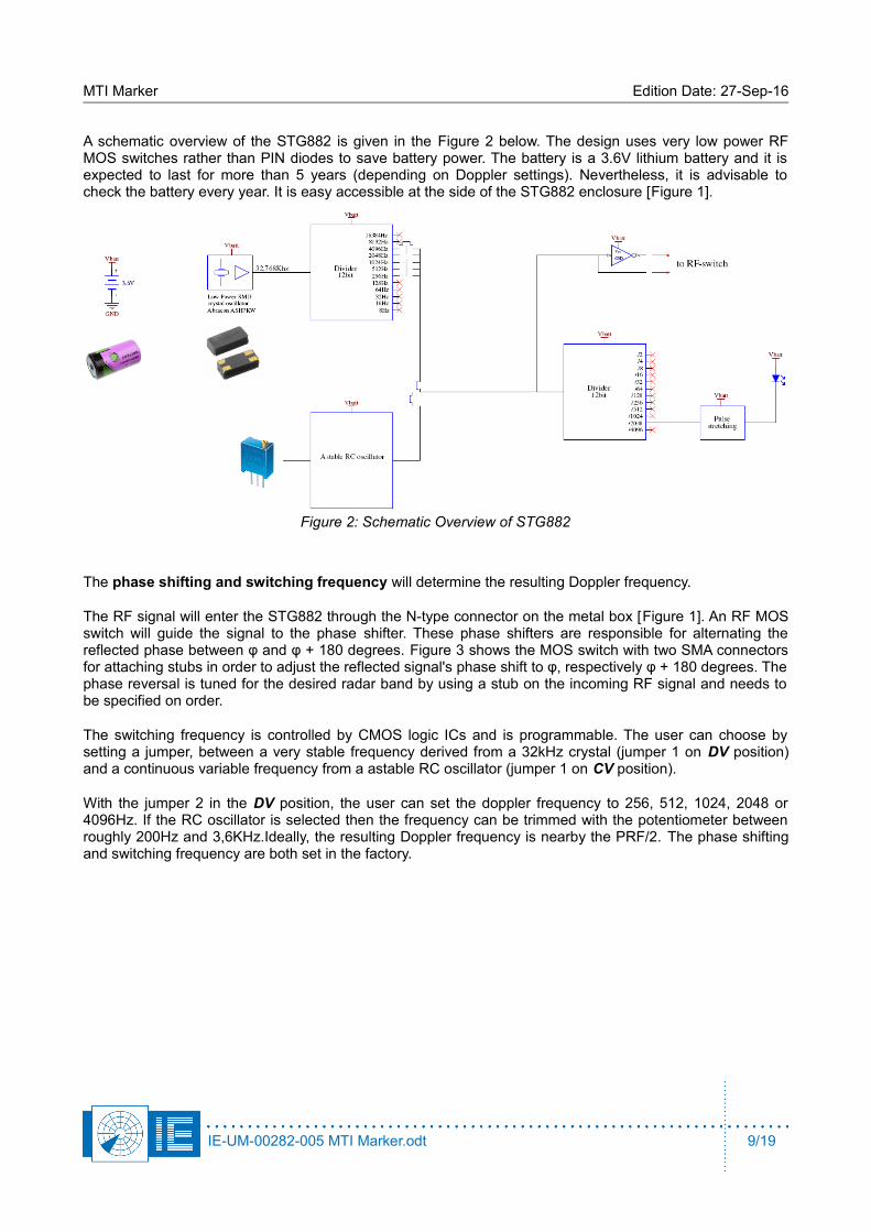
A schematic overview of the STG882 is given in the Figure 2 below. The design uses very low power RFMOS switches rather than PIN diodes to save battery power. The battery is a 3.6V lithium battery and it isexpected to last for more than 5 years (depending on Doppler settings). Nevertheless, it is advisable tocheck the battery every year. It is easy accessible at the side of the STG882 enclosure [Figure 1].
Figure 2: Schematic Overview of STG882
The phase shifting and switching frequency will determine the resulting Doppler frequency.
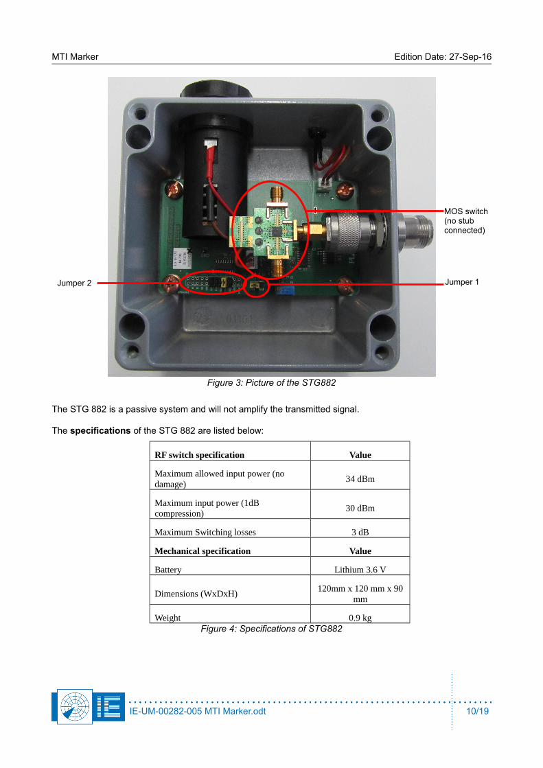
The RF signal will enter the STG882 through the N-type connector on the metal box [Figure 1]. An RF MOSswitch will guide the signal to the phase shifter. These phase shifters are responsible for alternating thereflected phase between φ and φ + 180 degrees. Figure 3 shows the MOS switch with two SMA connectorsfor attaching stubs in order to adjust the reflected signal's phase shift to φ, respectively φ + 180 degrees. Thephase reversal is tuned for the desired radar band by using a stub on the incoming RF signal and needs tobe specified on order.
The switching frequency is controlled by CMOS logic ICs and is programmable. The user can choose bysetting a jumper, between a very stable frequency derived from a 32kHz crystal (jumper 1 on DV position)and a continuous variable frequency from a astable RC oscillator (jumper 1 on CV position).
With the jumper 2 in the DV position, the user can set the doppler frequency to 256, 512, 1024, 2048 or4096Hz. If the RC oscillator is selected then the frequency can be trimmed with the potentiometer betweenroughly 200Hz and 3,6KHz.Ideally, the resulting Doppler frequency is nearby the PRF/2. The phase shiftingand switching frequency are both set in the factory.
IE-UM-00282-005 MTI Marker.odt 9/19
MTI Marker Edition Date: 27-Sep-16
The STG 882 is a passive system and will not amplify the transmitted signal.
The specifications of the STG 882 are listed below:
RF switch specification Value
Maximum allowed input power (no damage)
34 dBm
Maximum input power (1dB compression)
30 dBm
Maximum Switching losses 3 dB
Mechanical specification Value
Battery Lithium 3.6 V
Dimensions (WxDxH)120mm x 120 mm x 90
mm
Weight 0.9 kgFigure 4: Specifications of STG882
IE-UM-00282-005 MTI Marker.odt 10/19
Figure 3: Picture of the STG882
Jumper 2 Jumper 1
MOS switch(no stub connected)
MTI Marker Edition Date: 27-Sep-16
2.2. AntennaThe intended use of the MTI marker is crucial to determine which antenna is most appropriate to serve yourneeds. Several parameters will reflect on the antenna choice:
Polarisation of the PSR antenna
Distance to the PSR radar
Required gain
Mobility of the system
The polarisation of the PSR antenna will determine the orientation of the antenna. If possible a standardgain horn antenna is used. This way the exact gain and resulting strength of the target is accurately known.In case a circular polarisation is employed and a strong marker is needed, a parabolic antenna has to beinstalled.
The size of the horn antenna depends on the operating frequency and the required gain. The horn antennafor an L band PSR is larger than for an S band PSR for the same amount of amplification. The size of thehorn antenna also reflects on the mobility of the system.
An example which shows how to determine the necessary antenna: For an X-band system a simple20dB gain horn is sufficient as the high frequency allows a high gain antenna and still preserves a small sizewhile the target RCS needed is usually small on X-band. For L-band being long range radar systems, themarker antenna needs to be much bigger and if the range to the radar is only a few kilometres sometimesthe problem is that the received power is more than the MTI marker can handle (typical 20dBm).
2.3. Field Set-upOne has to consider the elevation between the MTI marker antenna and the PSR antenna. A PSR antennatypically has 6dB attenuation at horizon level. In case the MTI marker is on a low elevation far away from theradar, this will induce an extra 12dB (6dB up/down) attenuation of the RF signal. Therefore it is advisable tomove up in the vertical polar diagram (VPD), for instance by using a telescopic pole [Figure 3].
Although a natural high point in the environment might look tempting for installing the MTI marker, this doesnot always give the best results. It will definitely maximize the return power towards the radar as you moveup in the VPD, but unfortunately the ground clutter will be maximized as well.
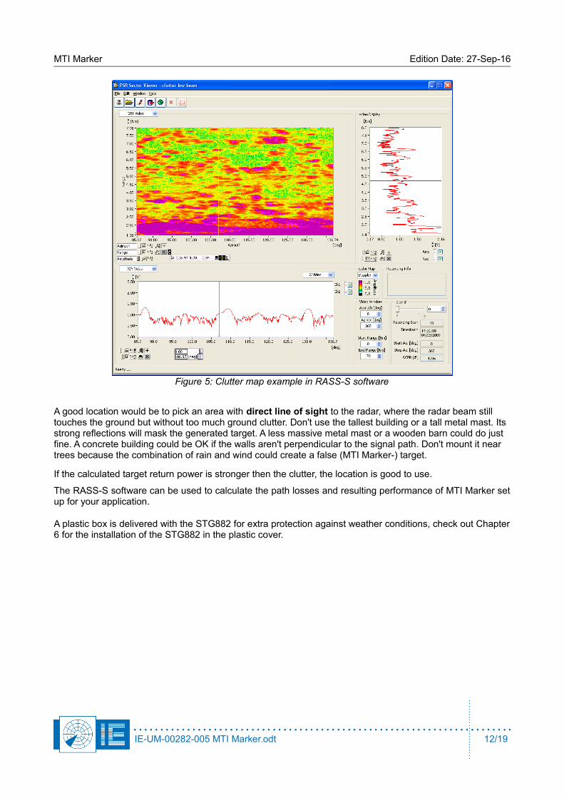
Therefore it is advised to measure a clutter map. This can be a Built In Test (BIT) function of the radar or one could make use of Intersoft Electronics' hardware and RASS-S software [Figure 5]. Verify the amount of clutter for a few possible locations. If the signal strength of the clutter is calibrated, it can be compared to the calculated power of the MTI marker assistant software for every candidate location.
IE-UM-00282-005 MTI Marker.odt 11/19
MTI Marker Edition Date: 27-Sep-16
A good location would be to pick an area with direct line of sight to the radar, where the radar beam still touches the ground but without too much ground clutter. Don't use the tallest building or a tall metal mast. Its strong reflections will mask the generated target. A less massive metal mast or a wooden barn could do just fine. A concrete building could be OK if the walls aren't perpendicular to the signal path. Don't mount it near trees because the combination of rain and wind could create a false (MTI Marker-) target.
If the calculated target return power is stronger then the clutter, the location is good to use.
The RASS-S software can be used to calculate the path losses and resulting performance of MTI Marker setup for your application.
A plastic box is delivered with the STG882 for extra protection against weather conditions, check out Chapter6 for the installation of the STG882 in the plastic cover.
IE-UM-00282-005 MTI Marker.odt 12/19
Figure 5: Clutter map example in RASS-S software

MTI Marker Edition Date: 27-Sep-16
3. THE MTI SETUP ASSISTANT
The MTI Setup Assistant (software tool) can be accessed via the MTI Marker button from the PSR Target Generation section in the RASS-S toolbox.
In the MTI Setup Assistant we can distinguish:• some fields to enter parameters• a VPD curve• a graphical representation of the setup
IE-UM-00282-005 MTI Marker.odt 13/19
Figure 6: PSR Target Generation section with MTI Marker button
Figure 7: MTI Setup Assistant
MTI Marker Edition Date: 27-Sep-16
The MTI Setup assistant needs some parameters of the radar, the MTI and the simulated target. The radar parameters include:
• Radar band: L-S, C or X
• Tx Power: Used to evaluate the theoretical input power of the MTI Marker
• Max Antenna Gain: Added to the TxPower to calculate the effective transmitter power
• Frequency: Used to calculate the path loss through space
Note: If the exact frequency is not known or if it changes during operation, enter the closestfrequency.
Also the VPD curve can be considered as s radar parameter. Use the VPD viewer tool in the toolbar to import an existing VPD diagram from text format.
The MTI Parameters include:
• MTI Antenna Gain: This is typical
◦ 10 dB for L-S band
◦ 20 dB for C band and X band in mobile setup
◦ 24 dB for X band in fixed setup
• Loss MTI: Loss induced by the MTI RF components, typical 2,5 dB if no attenuation is used
• Attenuation A: Optional attenuation value of attenuator or cable in line with the MTI antenna path, often used to lower the maximum RCS
The Target Parameters include:
• Elevation
• Range of the simulated target
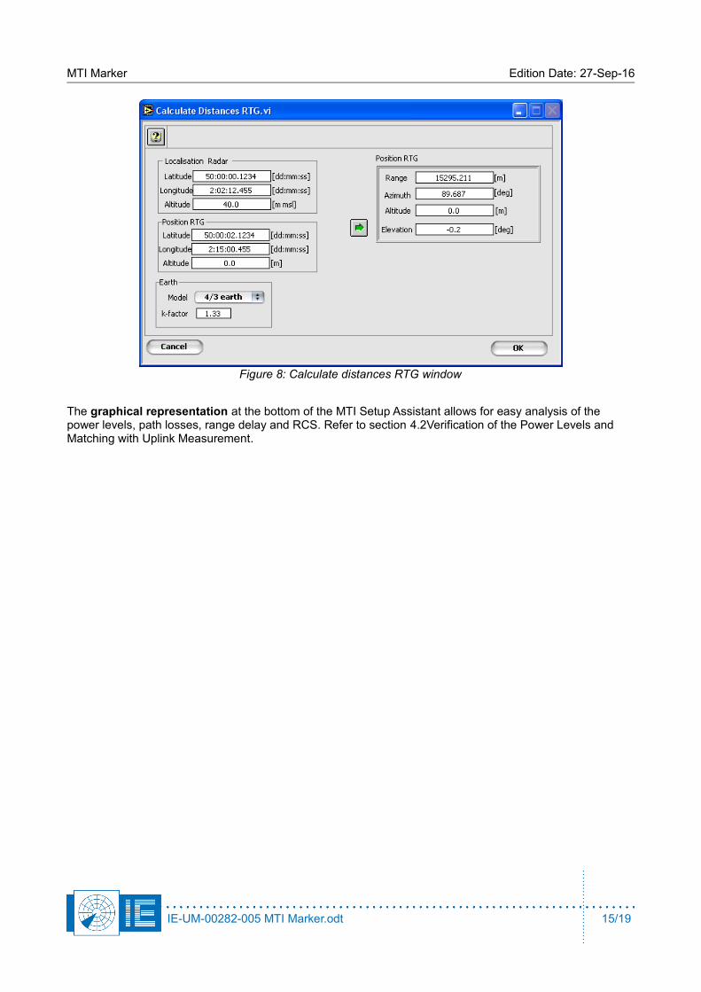
The range can be calculated based on the GPS coordinates of the radar and the MTI Marker using the
Calculate Range button. This button opens the Calculate Distances RTG window in which the coordinates can be entered [Figure 8]. The range can also be set by using the slider.
IE-UM-00282-005 MTI Marker.odt 14/19
G
MTI Marker Edition Date: 27-Sep-16
The graphical representation at the bottom of the MTI Setup Assistant allows for easy analysis of the power levels, path losses, range delay and RCS. Refer to section 4.2Verification of the Power Levels and Matching with Uplink Measurement.
IE-UM-00282-005 MTI Marker.odt 15/19
Figure 8: Calculate distances RTG window
MTI Marker Edition Date: 27-Sep-16
4. UTILIZATION INSTRUCTIONS
4.1. Verification of the Phase Flipping Rate
If, for example, the radar has a pulse repetition frequency of 240Hz, the rate of phase flipping should be different from 480Hz or 960Hz. If this is not the case, every radar echo would be generated using the same phase shift, no Doppler speed would be measurable and hence no target would be detected.
In order to avoid these situations, it is possible to verify the phase flipping rate. The twelfth bit of the oscillator, which controls the switch of the phase flipping, can be monitored as it is related to the flashing led indicator on the Stationary Target Generator.
Use a stopwatch to measure 10 periods (more accurate then one) of the flashing led indicator on the Stationary Target Generator. Divide the result by 10 and transfer it into a frequency. Multiply the result with 4096 to get the frequency of the phase flipping.
( Example: if the period is 40 seconds , the generated Doppler frequency would be 4096/(40/10) or 1024 Hz).
4.2. Verification of the Power Levels and Matching with Uplink Measurement
Open up the MTI Marker Setup Tool from the RASS-S toolbox, enter the required parameters as described in3The MTI Setup Assistant and verify the parameters of the setup.
The path loss (one way in gray ; two ways in blue) is calculated.
The target return power is calculated and it should be above the Minimum Detectable Signal strength of theradar. The corresponding RCS of the generated target is also calculated. This RCS doesn't change with the range of the setup. The return power will decrease for sure, but so does the return power of a real aircraft. The only thing that changes the simulated target size is the antenna gain of the MTI marker or additional attenuators put in line between the STG882 and its antenna.
Use the MTI Marker Setup tool to calculate and verify the power received by the MTI marker. Verifying the calculated power by an Uplink antenna measurement using the Intersoft RFA641 is advised. Use the antenna of the MTI marker to make the uplink measurement (but use appropriate attenuators and take them into account). Any mistake of the (assumed) antenna gain of the radar antenna or MTI marker will be revealed.
Make sure the Tx power is correct (the radar could be transmitting at half power instead of at peak power) and then adjust the parameters of the MTI antenna gain to match with the result of the uplink measurement.
IE-UM-00282-005 MTI Marker.odt 16/19
MTI Marker Edition Date: 27-Sep-16
5. MTI MARKER WITH OPTIONAL TEST FLIGHT SIMULATION
The antenna of the MTI Marker can be re-used when the RTG1002 (Radar Target Generator) is added to theset-up. This RTG1002 can be used as a Test Flight Simulator. Adding the RTG1002 to the set-up one candecide to switch to the RTG1002 instead of to the STG882 (Stationary Target Generator).
Often, expensive test flights are used during the SAT procedure of radar systems, since this procedure testsall the important elements of the radar. However a few downsides of this method should be noted: the testflights are very expensive and the Radar Cross Section (RCS) varies with the orientation and type of theaircraft. The latter indicates that the calibration of the RCS is not easy and therefore it is difficult to accuratelyreproduce a test flight.
For SSR a valuable and much cheaper alternative solution, the Radar Environment Simulator (RES28x) isavailable to fully test the performance of the radar. For PSR the diversity of systems and the complexity ofgenerating signals that simulate the environment makes it difficult to use a complete RES. The amount oftest flights for recurring maintenance procedures and quality control of the PSR can now be reducedsignificantly by using the new RTG1002 (Radar Target Generator) with programmable RCS. The RTG1002 isable to generate the reflecting signals of an aircraft faithfully and independent of the radar characteristics(frequency, PRF, etc.).
In order to test the complete radar system it is necessary to generate the aircraft signals in the field therebyincluding the antenna system. The set-up position should be chosen carefully and the site attenuation shouldbe calibrated.
Different test scenarios, in function of range and velocity, can be simulated to test the Doppler MTI functionand blind speeds. The accuracy of the radar system can be determined when the simulated trajectory iscompared to the output of the radar system (ASTERIX). For this purpose the RASS-S software provides thematching tools. The method described is a feasible, repeatable and low-cost replacement for the expensivetest flights and offers a standardized and calibrated maintenance procedure.
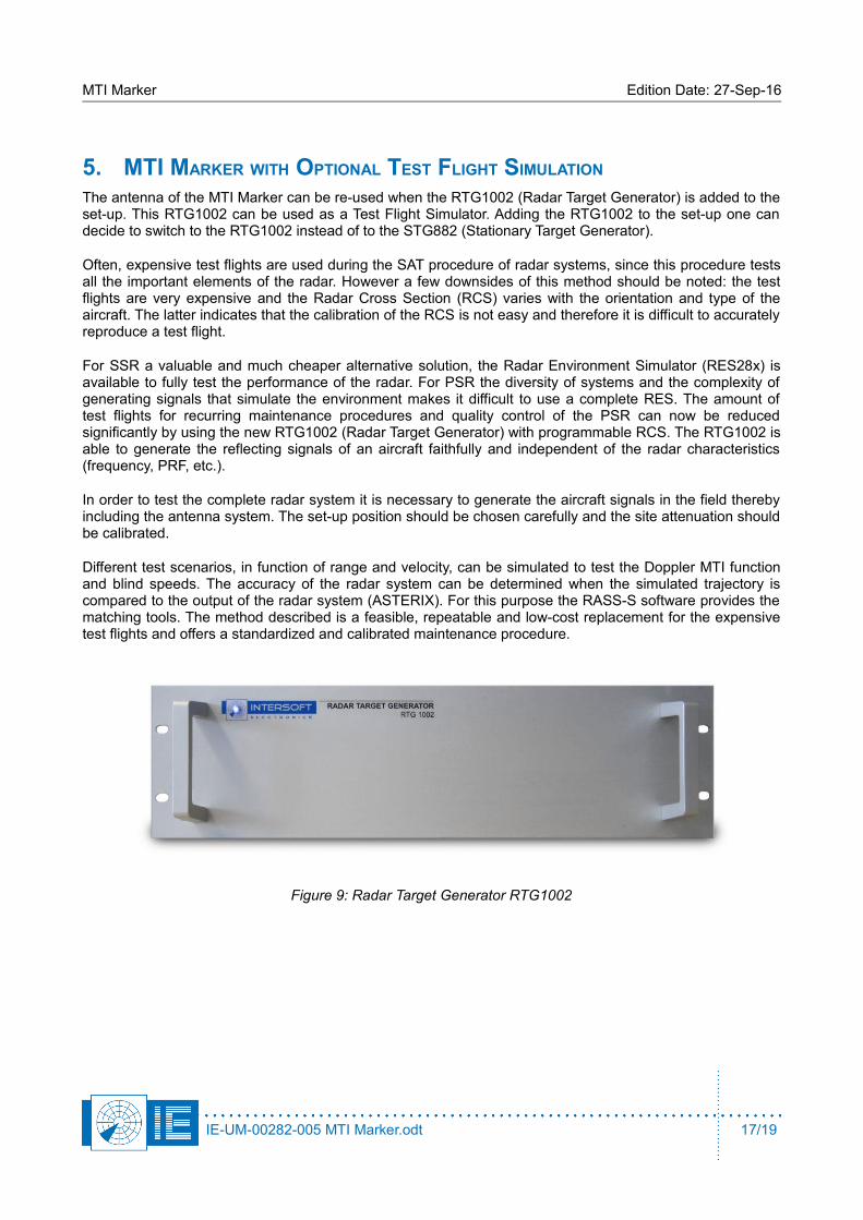
Figure 9: Radar Target Generator RTG1002
IE-UM-00282-005 MTI Marker.odt 17/19
MTI Marker Edition Date: 27-Sep-16
6. APPENDIX: INSTALLING STG882 INTO PLASTIC COVER
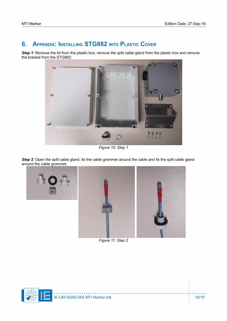
Step 1: Remove the lid from the plastic box, remove the split cable gland from the plastic box and remove the bracket from the STG882:
Step 2: Open the split cable gland, fix the cable grommet around the cable and fix the split cable gland around the cable grommet.
IE-UM-00282-005 MTI Marker.odt 18/19
Figure 10: Step 1
Figure 11: Step 2

MTI Marker Edition Date: 27-Sep-16
Step 3: Put the STG882 inside the plastic box, fix the cable to the STG882 using the SMA-N adapter and fix the split cable gland to the plastic box.
Step 4: Close the front side of the plastic box and fix the bracket onto the STG882 (backside of the plastic box).
IE-UM-00282-005 MTI Marker.odt 19/19
Figure 12: Step 3
Figure 13: Step 4