msr team savi - university of colorado boulder of a sheet of paper) simulated telescoping camera...
TRANSCRIPT

MSR Team SAVI Satellite Active Vibration Inverter
Wasseem Bel Joseph Schmitz
Patrick Byrne Justin Tomasetti
Blake Firner Jackson Vlay
Corey Hyatt Benjamin Zatz
Project Purpose
2
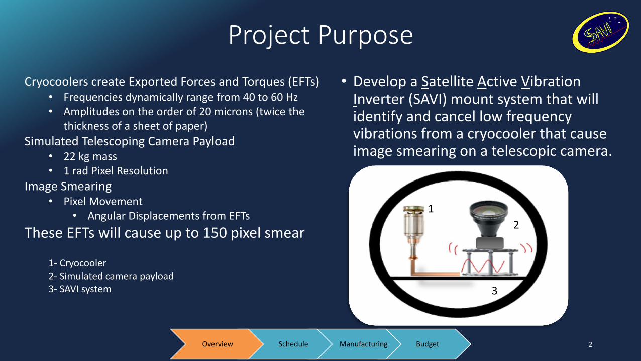
• Develop a Satellite Active Vibration Inverter (SAVI) mount system that will identify and cancel low frequency vibrations from a cryocooler that cause image smearing on a telescopic camera.
1 1
2
3
Cryocoolers create Exported Forces and Torques (EFTs) • Frequencies dynamically range from 40 to 60 Hz • Amplitudes on the order of 20 microns (twice the
thickness of a sheet of paper)
Simulated Telescoping Camera Payload • 22 kg mass • 1 rad Pixel Resolution
Image Smearing • Pixel Movement
• Angular Displacements from EFTs
These EFTs will cause up to 150 pixel smear 1- Cryocooler 2- Simulated camera payload 3- SAVI system
Budget Manufacturing Schedule Overview
SAVI and Test Stand Details
3
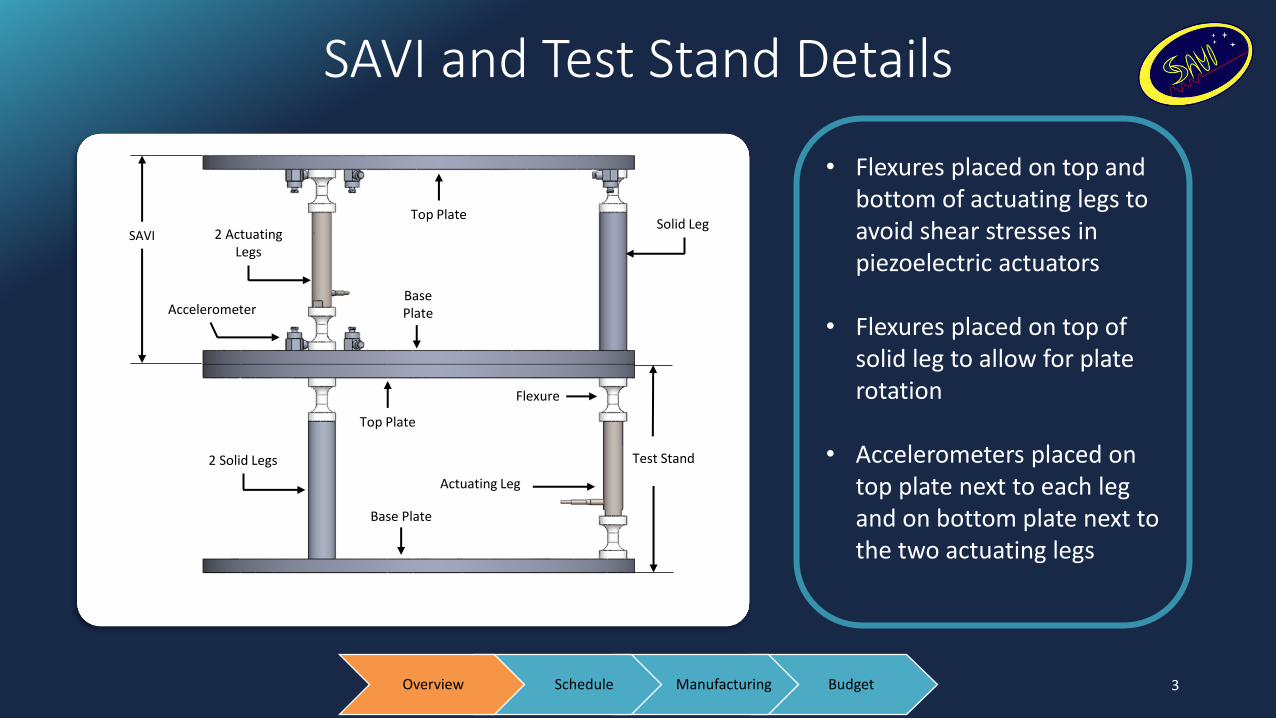
• Flexures placed on top and bottom of actuating legs to avoid shear stresses in piezoelectric actuators
• Flexures placed on top of solid leg to allow for plate rotation
• Accelerometers placed on top plate next to each leg and on bottom plate next to the two actuating legs
SAVI 2 Actuating Legs
Accelerometer
2 Solid Legs
Top Plate
Base Plate
Top Plate
Base Plate
Actuating Leg
Flexure
Test Stand
Solid Leg
Budget Manufacturing Schedule Overview
Levels of Success
Level 1: • Pixel smear reduced by 60% to about 60 pixels of smear
Level 2: • Pixel smear reduced by 80% so that about 30 pixels or fewer are smeared
• Signal frequency has dwell time of 2 seconds
Level 3: • The system dimensions will not exceed 20 cm x 20 cm x 10 cm
• The system mass will not exceed 5 kg
• The system will use no more than 10 W of power
4 Budget Manufacturing Schedule Overview
Critical Project Elements
• Flexture • Longitudinally rigid
• Laterally flexible
• Mitigates shear stresses on Actuators
• Epoxy • Soluble
• Be able to bond all materials
• Negligible vibration damping in compression
• Modal Analysis • Modes must not exist in 40 – 60 Hz range
• DAQ Error • Possible aliasing
• Amplitude error is frequency dependent
5 Budget Manufacturing Schedule Overview

Updates
• Accelerometer Calibration • Previously mentioned drop test in FFR has been discarded • Cannot be statically tested for accuracy • Borrowed accelerometers are being sent to PCB Piezotronics to be
recalibrated
• Recessed mount holes for struts on plates • Improved alignment of the struts (accuracy is critical) • Allows for increased flexure size -> Resonance modes of system are distanced
from the operating frequency range
• A laser will be used to verify the full system • Tests will be done at Ball Aerospace -> new noise test data is needed
6 Budget Manufacturing Schedule Overview

Schedule of Major Milestones
7 Budget Manufacturing Schedule Overview
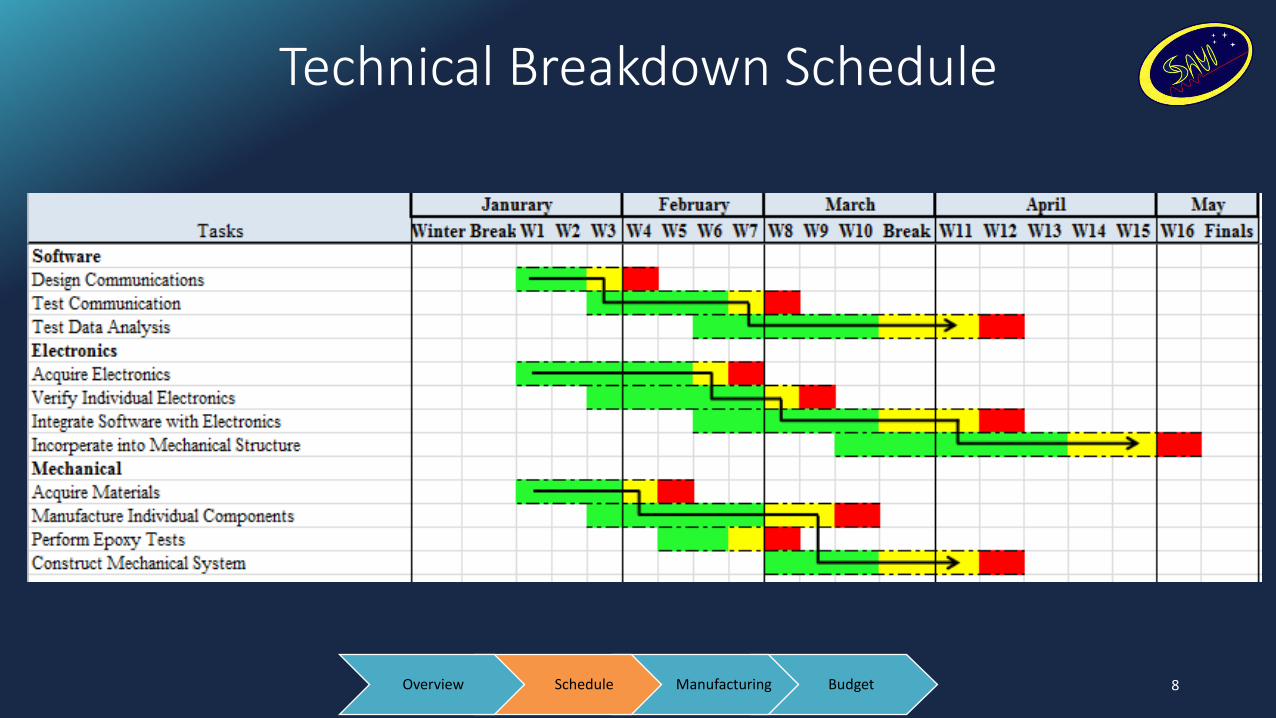
Technical Breakdown Schedule
8 Budget Manufacturing Schedule Overview

SAVI Communication
9 Budget Manufacturing Schedule Overview
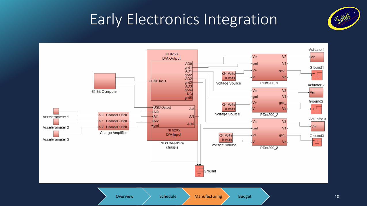
Early Electronics Integration
10 Budget Manufacturing Schedule Overview

Plans for Final Circuit
11
Two PCB boards stacked PCB Board 1 (Left): • 2 Banana clip panel mounts • 3 BNC surface mounts PCB Board 2 (Below) • 5 Resistors - 860Ω • 5 Capacitors – 2.2μF • 5 BNC surface mounts
Budget Manufacturing Schedule Overview

Software Recap
• After Fall semester, many of the technical software elements were completed including: • EFT wave determination routines • Wave inversion and output • Simulink Model predicting software performance.
• What needed further development: • Interfacing with electronics
• Continuous DAQ input and output to capture accelerometer data and drive actuators, respectively.
• Real time computation of prediction wave using real sensor data
12
To PDm’s
From C65’s
Budget Manufacturing Schedule Overview

Software Development
• Software/Electronics Interfacing Developments: • Input and output infrastructure complete
• Software now capable of electronics integration with the following capabilities: • Account for individual electronics calibration and varying
sensitivities of parts
• Generate arbitrary output disturbance in real time
• Acquire accelerometer data in real time
• Compute EFT from accelerometer data in real time
13 Budget Manufacturing Schedule Overview

Software and Electronics Demonstration
• To demonstrate software and electronics capabilities: • Constructed demonstration consisting of:
• Software • cDAQ with NI-9263 and NI 9205 • PDm200 • Unloaded piezo-electric stack • C65 Accelerometer
• Purpose is to demonstrate: • Continuous voltage output
• Properly drive Piezo-electric stack disturbance up to 100V
• Continuous sensor input • Sense micron level vibrations
• Real time calculation of EFT prediction using real accelerometer data being driven by micron level piezoelectric stack displacements. 14
PDm200
cDAQ Signal
Conditioner
Actuator C65
NI-9263 NI-9205
Budget Manufacturing Schedule Overview

Demonstration Results
15
• EFT prediction created in real time using accelerometer data.
• Tracking of frequency prediction during a frequency sweep
• Adjustment to a change in EFT disturbance in 1 8 dwell time
Budget Manufacturing Schedule Overview

Demonstration Issues
16
Sampling Rate: 4096 Hz Sampling Rate: 16304 Hz
• Sampling rate of the DAQ affects amplitude of the acceleration data it records • Frequency is unaffected • Sampling frequency must be at least 16kHz to achieve desired actuator displacements
Budget Manufacturing Schedule Overview

Top and Bottom Plate
• Changes in design: • Small pockets created on all plates to
assist in vertical alignment • Depth: 0.254 cm • Diameter: 1.27 cm
• Flexures and legs will be epoxied into holes
• Manufacture: • Generated SolidCAM code for CNC mill
to machine top and bottom plates • Edges sanded for smooth surface
• Manufactured top and bottom plate
17 Budget Manufacturing Schedule Overview

Cyberbond Apollo 2150
• Leg to Flexure Connection • 0.159 cm
• Leg to Plate Connection • 0.159 cm
• Plate to Plate Connection • 0.159 cm
• Surfaces will be treated and sand blasted in order to maximize bond strength
18 Budget Manufacturing Schedule Overview

Flexures
19
• Flexures to be manufactured with CNC Lathe • Lathe was inoperable due to wrong parts
• New parts have been installed and machine is almost operational. • Flexures should be machined this week
• Due to the hole recession of the plates, the flexures were able to be increased in length
Budget Manufacturing Schedule Overview
1.27 cm
0.508 cm
0.381 cm
2.26 cm
0.254 cm
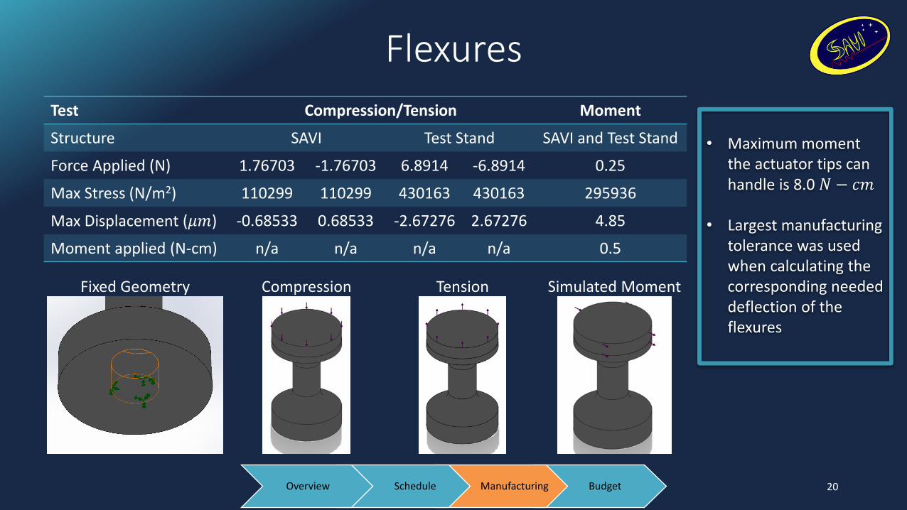
Flexures
Test Compression/Tension Moment
Structure SAVI Test Stand SAVI and Test Stand
Force Applied (N) 1.76703 -1.76703 6.8914 -6.8914 0.25
Max Stress (N/m2) 110299 110299 430163 430163 295936
Max Displacement (𝜇𝑚) -0.68533 0.68533 -2.67276 2.67276 4.85
Moment applied (N-cm) n/a n/a n/a n/a 0.5
20
• Maximum moment
the actuator tips can handle is 8.0 𝑁 − 𝑐𝑚
• Largest manufacturing
tolerance was used when calculating the corresponding needed deflection of the flexures
Fixed Geometry Compression Tension Simulated Moment
Budget Manufacturing Schedule Overview

Modal Analysis SAVI and Test Stand
Mode Frequency (Hz) and
Bandwidth Description
1 10.287±0.103 Top plate of SAVI pivoting about solid leg in the horizontal plane
2 27.042±0.270 SAVI and Test Stand swaying from side to side (Base Fixed)
3 28.609±0.286 SAVI and Test Stand twisting back and fourth (Base Fixed)
4 110.6±1.106 Center Plates moving side-to-side in the Horizontal Plane
5 114.93±1.149 Center Plates moving side-to-side in the Horizontal Plane (60 degree shift)
21 Budget Manufacturing Schedule Overview

Financial Layout
22
Item Quantity Item Cost ($) Shipping ($) Total Item Cost ($)
PDm200 3 230 30 720
P-820.20 3 646 50 1988.00
Laser and Safety Goggles 1 119.90 15 134.90
Building Material: Plates, Rods and Simulated Mass
1 147.91 24.95 172.86
AE0505D16F Actuator 1 88 30 118
Extra Plates 2 14.80 6.99 36.59
Replacement Plates 4 20.28 8.91 90.03
Misc. Supplies 41.08 0 41.08 Remaining Budget
Total Cost $ 3270.48 $ 1729.52
Budget Manufacturing Schedule Overview

List of Components
23
Items Received • Building materials: Plates, Rods
and Simulated Mass
• PDm200 Drivers
• AE0505D16F Actuator
Items Awaiting Delivery • P-820.20 Actuators
• Laser and Safety Goggles
Items Not Yet Ordered • Epoxy and Solvent
Budget Manufacturing Schedule Overview
Backup Slides
24

Critical Project Elements
• Data Input and Output from MATLAB Interface
• NI CompactDAQ
• Capable of communicating with MATLAB
• Queued data I/O directly into MATLAB
• For maintaining a processing speed to mitigate output signal phase error
• Characterize 20 𝜇m EFT Vibration
• Find frequency (𝑓), amplitude (𝐴) and phase (𝜃) from noisy accelerometer data
• Collected errors in frequency, phase and amplitude must meet residual requirements
• Accelerometers
• PCB C65 – Piezoelectric accelerometer
• Must be able to measure system level vibrations
• Actuators
• PI 820.2 – Piezoelectric actuator
• Must be able to have submicron resolution while under the payload
• Actuator Driver
• PDm200 – Voltage amplifier and signal conditioner
• Must be able to run actuator within specifications
• Must be compatible with DAQ system
• NI CompactDAQ with modules
• NI 9205 – Analog to digital voltage measurement
• Must be able to sample system level vibrations
• NI 9263 – Digital to analog voltage output
• Must be able to provide input voltage to PDm200
• Structural
• Flexure
• Longitudinally rigid and laterally flexible to allow flexibility and mitigate shear stresses
• Base/top plate and solid leg
• Sufficient stiffness to be approximated as a rigid element
• Electronic components
• Electronic mounting capability
• Connections
• Materials compatible with epoxy chosen
• Analysis
• Modeled in CAD (SolidWorks)
• Able to produce force and vibration analysis
• Able to confirm flexure deflection with system loads
25