msp430-based e-metering and amr solutions done€“ some of the latest meters have automatic meter...
TRANSCRIPT
1
5/22/2008 1
MSP430-based E-metering and AMR solutionsKripasagar Venkat
2
Agenda
• Introduction to Energy metering (E-metering)• MSP430 for E-metering• MSP430 System on Chip (SoC) and peripherals• MSP430 Metrology and Calibration• AMR and PLC solutions• MSP430 E-metering solutions• Demos
2
3
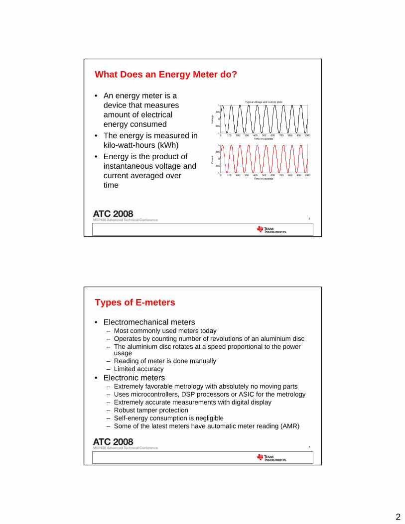
What Does an Energy Meter do?
• An energy meter is a device that measures amount of electrical energy consumed
• The energy is measured in kilo-watt-hours (kWh)
• Energy is the product of instantaneous voltage and current averaged over time
0 100 200 300 400 500 600 700 800 900 1000-1
-0.5
0
0.5
1
Time in seconds
Vol
tage
Typical voltage and current plots
0 100 200 300 400 500 600 700 800 900 1000-1
-0.5
0
0.5
1
Time in seconds
Cur
rent
4
Types of E-meters
• Electromechanical meters– Most commonly used meters today– Operates by counting number of revolutions of an aluminium disc– The aluminium disc rotates at a speed proportional to the power
usage– Reading of meter is done manually– Limited accuracy
• Electronic meters– Extremely favorable metrology with absolutely no moving parts– Uses microcontrollers, DSP processors or ASIC for the metrology– Extremely accurate measurements with digital display– Robust tamper protection – Self-energy consumption is negligible– Some of the latest meters have automatic meter reading (AMR)
3
5
Types of measurements
• Single phase measurement– Common in most residential complexes– One voltage and one current– Supports low to medium load
• Dual phase measurement– Not common– Two voltage separated by 180 degrees– Supports medium to large load
• Three phase measurement– Consists of 3 separate phases or wires to distribute AC current– Each phase is 120 degrees out of phase with the others– It is more efficient to transmit current via 3-phases that are out of
phase than a single phase system– Especially designed for applications that service large loads
6
Agenda
• Introduction to Energy metering (E-metering)• MSP430 for E-metering• MSP430 System on Chip (SoC) and peripherals• MSP430 Metrology and Calibration• AMR and PLC solutions• MSP430 E-metering solutions• Demos
4
7
Why choose MSP430?• Low-power + High performance• Modern 16-bit RISC CPU• Up to 192KB Flash and up to 16KB RAM• Up to 25MHz powerful clock system w/ <6µs clock start-up• Powerful analog front-end to form a System-on-Chip (SoC)• Intelligent peripherals that boost performance• 0.1µA power down/ 0.8µA standby mode • Integrated LCD driver with charge pump to support up to
160 segments• Embedded emulation
8
MSP430 for E-metering?
• Powerful 16-bit A/D converter (SD16, SD16_A) with programmable gain amplifier
• SD16/SD16_A supports differential input• Multiple SD16/SD16_A for simultaneous sampling of voltage and
current channels• Hardware multiplier to support up to 32-bit x 32-bit multiply for better
accuracy• Multiple communication peripherals that support a variety of wired and
wireless protocols• Support for anti-tampering• Calculates a comprehensive set of parameters with the use of a CPU
independent metrology engine
5
9
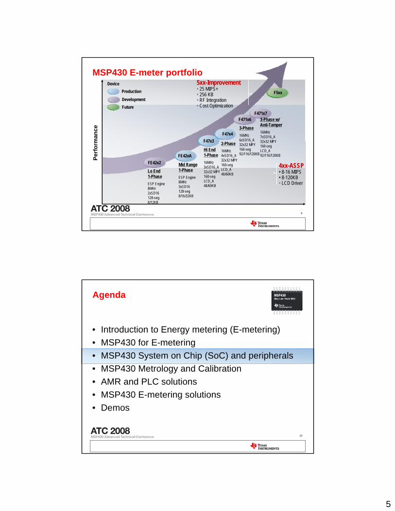
MSP430 E-meter portfolio
Perf
orm
ance
Development
ProductionDevice
4xx-ASSP • 8-16 MIPS• 8-120KB• LCD Driver
FE42xA
5xx-Improvement• 25 MIPS+• 256 KB • RF Integration• Cost Optimization
Hi End 1-Phase16MHz 3xSD16_A 32x32 MPY 160-seg LCD_A 48/60KB
2-Phase16MHz 4xSD16_A 32x32 MPY 160-seg LCD_A 48/60KB
3-Phase16MHz 6xSD16_A 32x32 MPY 160-seg 92/116/120KB
Mid Range 1-PhaseESP Engine 8MHz 3xSD16 128-seg 8/16/32KB
Lo End 1-PhaseESP Engine 8MHz 2xSD16 128-seg 8/12KB
FE42x2
F471x6
F47x3F47x4
F471x73-Phase w/ Anti-Tamper16MHz 7xSD16_A 32x32 MPY 160-seg LCD_A 92/116/120KB
F5xx
Future
10
Agenda
• Introduction to Energy metering (E-metering)• MSP430 for E-metering• MSP430 System on Chip (SoC) and peripherals• MSP430 Metrology and Calibration• AMR and PLC solutions• MSP430 E-metering solutions• Demos
6
11
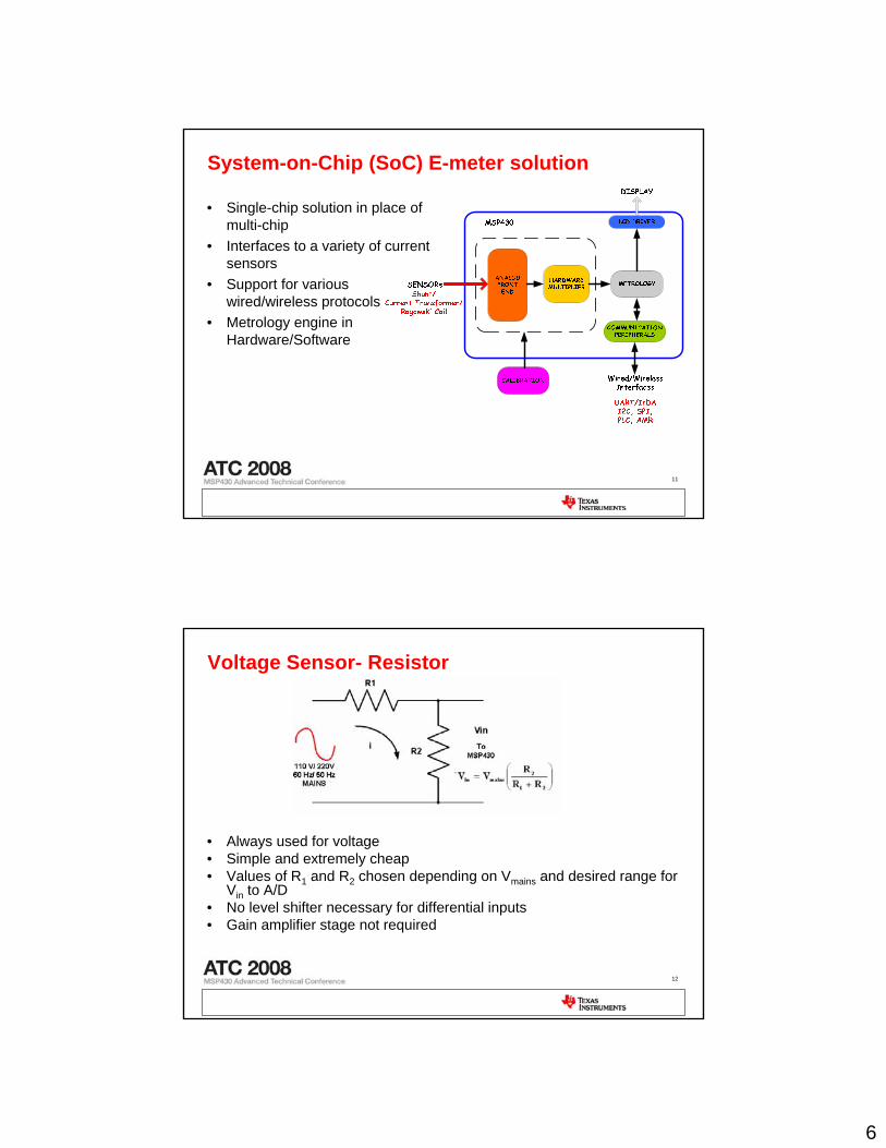
System-on-Chip (SoC) E-meter solution
• Single-chip solution in place of multi-chip
• Interfaces to a variety of current sensors
• Support for various wired/wireless protocols
• Metrology engine in Hardware/Software
12
Voltage Sensor- Resistor
• Always used for voltage• Simple and extremely cheap• Values of R1 and R2 chosen depending on Vmains and desired range for
Vin to A/D• No level shifter necessary for differential inputs• Gain amplifier stage not required
7
13
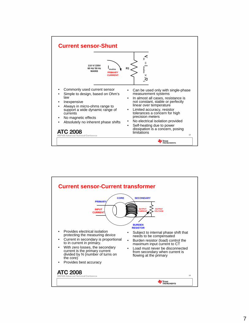
Current sensor-Shunt
• Commonly used current sensor• Simple to design, based on Ohm’s
law• Inexpensive• Always in micro-ohms range to
support a wide dynamic range of currents
• No magnetic effects• Absolutely no inherent phase shifts
R1110 V/ 220V60 Hz/ 50 Hz
MAINS PRIMARY CURRENT
1I
R×
=mains
inV
mainsI
• Can be used only with single-phase measurement systems
• In almost all cases, resistance is not constant, stable or perfectly linear over temperature
• Limited accuracy, resistor tolerances a concern for high precision meters
• No electrical isolation provided• Self-heating due to power
dissipation is a concern, posing limitations
14
Current sensor-Current transformer
• Provides electrical isolation protecting the measuring device
• Current in secondary is proportional to in current in primary.
• With zero losses, the secondary current is the primary current divided by N (number of turns on the core)
• Provides best accuracy
INPUT CURRENT
OUTPUT CURRENT
OUTPUT VOLTAGE
PRIMARYSECONDARY
BURDENRESISTOR
CORE
• Subject to internal phase shift that needs to be compensated
• Burden resistor (load) control the maximum input current to CT
• Load must never be disconnected from secondary when current is flowing at the primary
8
15
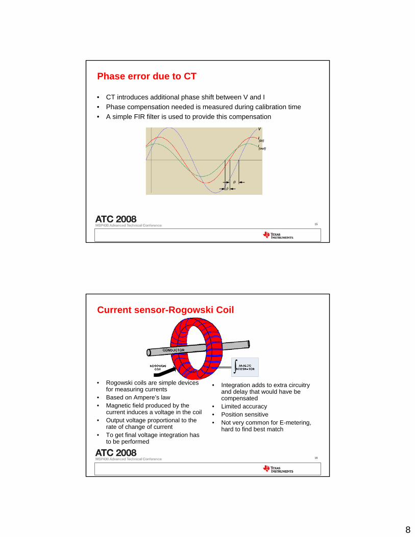
Phase error due to CT
• CT introduces additional phase shift between V and I• Phase compensation needed is measured during calibration time• A simple FIR filter is used to provide this compensation
16
Current sensor-Rogowski Coil
• Rogowski coils are simple devices for measuring currents
• Based on Ampere’s law• Magnetic field produced by the
current induces a voltage in the coil• Output voltage proportional to the
rate of change of current• To get final voltage integration has
to be performed
∫• Integration adds to extra circuitry
and delay that would have be compensated
• Limited accuracy• Position sensitive• Not very common for E-metering,
hard to find best match
9
17
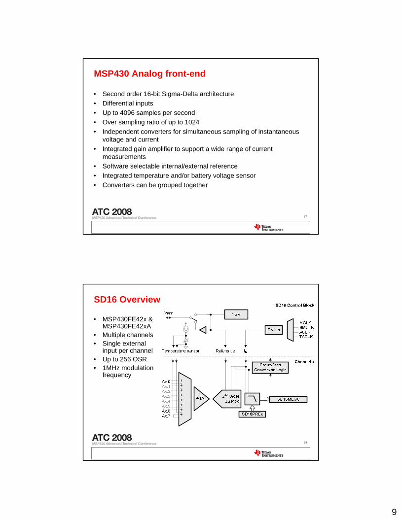
MSP430 Analog front-end
• Second order 16-bit Sigma-Delta architecture• Differential inputs • Up to 4096 samples per second• Over sampling ratio of up to 1024• Independent converters for simultaneous sampling of instantaneous
voltage and current• Integrated gain amplifier to support a wide range of current
measurements• Software selectable internal/external reference• Integrated temperature and/or battery voltage sensor• Converters can be grouped together
18
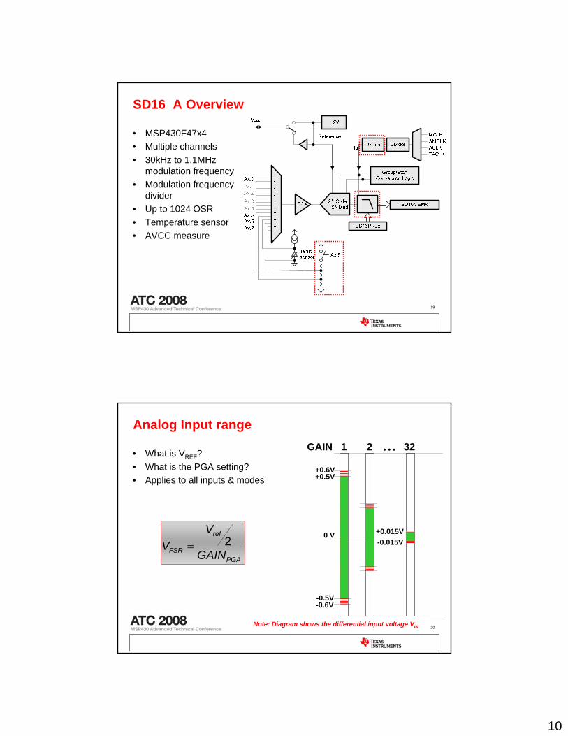
SD16 Overview
• MSP430FE42x & MSP430FE42xA
• Multiple channels• Single external
input per channel• Up to 256 OSR• 1MHz modulation
frequency
10
19
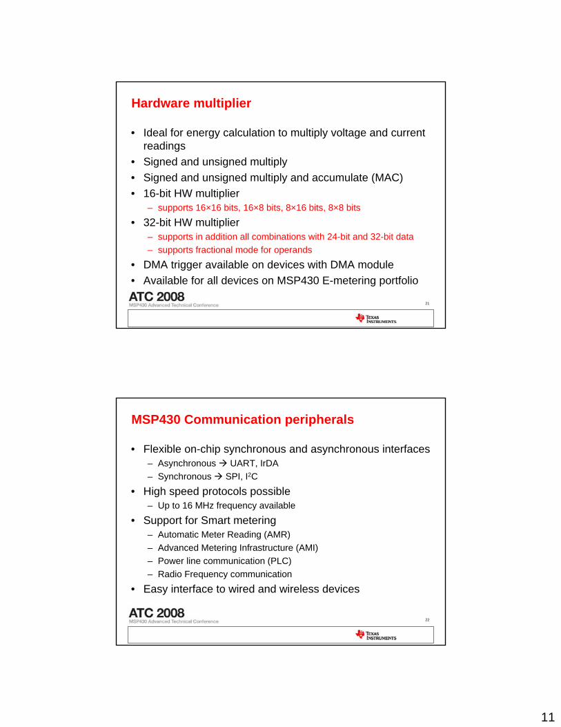
SD16_A Overview
• MSP430F47x4• Multiple channels• 30kHz to 1.1MHz
modulation frequency• Modulation frequency
divider• Up to 1024 OSR• Temperature sensor• AVCC measure
20
Analog Input range
• What is VREF?• What is the PGA setting?• Applies to all inputs & modes
GAIN 1 2 32
0 V
+0.6V
-0.6V
+0.5V
-0.5V
• • •
-0.015V+0.015V
PGA
ref
FSR GAIN
VV 2=
Note: Diagram shows the differential input voltage VIN
11
21
Hardware multiplier
• Ideal for energy calculation to multiply voltage and current readings
• Signed and unsigned multiply• Signed and unsigned multiply and accumulate (MAC)• 16-bit HW multiplier
– supports 16×16 bits, 16×8 bits, 8×16 bits, 8×8 bits
• 32-bit HW multiplier– supports in addition all combinations with 24-bit and 32-bit data– supports fractional mode for operands
• DMA trigger available on devices with DMA module• Available for all devices on MSP430 E-metering portfolio
22
MSP430 Communication peripherals
• Flexible on-chip synchronous and asynchronous interfaces– Asynchronous UART, IrDA– Synchronous SPI, I2C
• High speed protocols possible– Up to 16 MHz frequency available
• Support for Smart metering– Automatic Meter Reading (AMR) – Advanced Metering Infrastructure (AMI) – Power line communication (PLC) – Radio Frequency communication
• Easy interface to wired and wireless devices
12
23
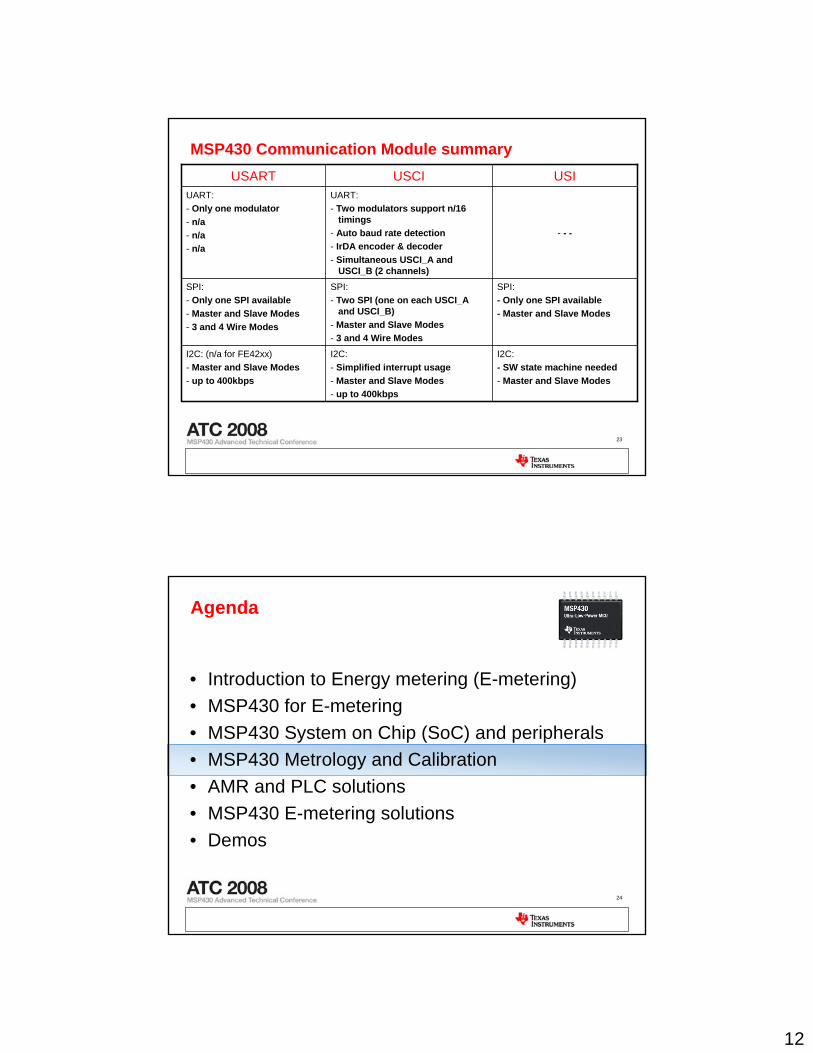
MSP430 Communication Module summary
I2C:- SW state machine needed- Master and Slave Modes
I2C:- Simplified interrupt usage- Master and Slave Modes - up to 400kbps
I2C: (n/a for FE42xx)- Master and Slave Modes- up to 400kbps
SPI:- Only one SPI available- Master and Slave Modes
SPI:- Two SPI (one on each USCI_A
and USCI_B)- Master and Slave Modes- 3 and 4 Wire Modes
SPI:- Only one SPI available- Master and Slave Modes- 3 and 4 Wire Modes
- - -
UART:- Two modulators support n/16
timings- Auto baud rate detection- IrDA encoder & decoder- Simultaneous USCI_A and
USCI_B (2 channels)
UART:- Only one modulator- n/a- n/a- n/a
USIUSCI USART
24
Agenda
• Introduction to Energy metering (E-metering)• MSP430 for E-metering• MSP430 System on Chip (SoC) and peripherals• MSP430 Metrology and Calibration• AMR and PLC solutions• MSP430 E-metering solutions• Demos
13
25
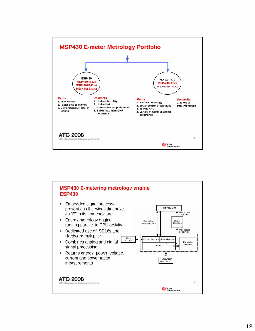
MSP430 E-meter Metrology Portfolio
ESP430MSP430FE42x
MSP430FE42xAMSP430FE42x2
NO ESP430MSP430F47xxMSP430F471xx
Merits1. Ease of use2. Faster time to market3. Comprehensive sets of results
De-merits1. Limited flexibility2. Limited set of communication peripherals3. 8 MHz maximum CPU frequency
Merits1. Flexible metrology2. Better control of accuracy3. 16 MHz CPU4. Variety of communication peripherals
De-merits1. Effort of implementation
26
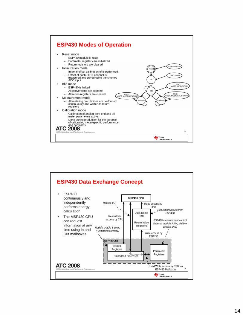
MSP430 E-metering metrology engineESP430
• Embedded signal processor present on all devices that have an “E” in its nomenclature
• Energy metrology engine running parallel to CPU activity
• Dedicated use of SD16s and Hardware multiplier
• Combines analog and digital signal processing
• Returns energy, power, voltage, current and power factor measurements
SD16/SD16_A
HARDWAREMULTIPLIER
14
27
ESP430 Modes of Operation• Reset mode
– ESP430 module is reset– Parameter registers are initialized– Return registers are cleared
• Initialization mode– Internal offset calibration of is performed.– Offset of each SD16 channel is
measured and stored using the shunted ADC input
• Idle mode– ESP430 is halted– All conversions are stopped– All return registers are cleared
• Measurement mode– All metering calculations are performed
continuously and written to return registers
• Calibration mode– Calibration of analog front-end and all
meter parameters active. – Done during production for the purpose
of calibrating meter-specific performance and constants.
28
ESP430 Data Exchange Concept
ESP430CE1
MSP430 CPU
Embedded Processor
ControlRegisters
ParameterRegisters
Dual accessRAM
Return ValueRegisters
Read/Writeaccess by CPU
Read access byCPU
Write access byESP430
Read/Write access by CPU viaESP430 Mailboxes
Calculated Results fromESP430
Module enable & setup(Peripherial Memory)
ESP430 measurement control(Internal module RAM, Mailbox
access-only)
Mailbox I/O
• ESP430 continuously and independently performs energy calculation
• The MSP430 CPU can request information at any time using In and Out mailboxes
15
29
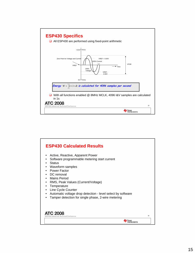
ESP430 SpecificsAll ESP430 are performed using fixed-point arithmetic
With all functions enabled @ 8MHz MCLK, 4096 I&V samples are calculated in 1s
Energy ∫∞=
=
××=t
t
dtivW0
is calculated for 4096 samples per second
+3.6V
100%Voltage
100% Current
AVcc
AVss0V
VREF + 0.50V
VFSRTime
ϕ
VREF -0.50V
Zero Point for Voltage and Current
VREF
30
ESP430 Calculated Results
• Active, Reactive, Apparent Power• Software programmable metering start current• Status• Waveform samples• Power Factor• DC removal• Mains Period• RMS, Peak Values (Current/Voltage)• Temperature• Line Cycle Counter• Automatic voltage drop detection - level select by software• Tamper detection for single phase, 2-wire metering
16
31
Non-ESP430 devices
• Code flexibility provides the choice of some/all computation results in comparison to ESP430
• Use of 32-bit x 32-bit HW multiplier aims towards better accuracy at lower CPU overhead
• Higher clock speed increases efficiency and add to capabilities• More memory means more features• Support for dual and three-phase measurements• Support for increased LCD segments • Better features in flash• Support for faster communication protocols
32
Calibration
• Mandatory for every meter• Corrects inherent errors
– Digital Phase Correction (Current channels)– Offset Correction (Current, Voltage)– Gain Correction (Current, Voltage)– Power Offset
• Single point and double point calibration – If the single point calibration is used, only the slope (Gain Correction) is calculated – If the double point calibration is used, the slope (Gain Correction) and the offset
(Power Offset) are calculated• Two calibration methods are possible
– Measurement of energy for a defined number of periods of the mains (ESP430 Calibration Mode is used for example)
– Continuous measurement mode: Energy accumulation for a single period of mains or fixed measurements (Ex: 4096) is compared using a calibration equipment
17
33
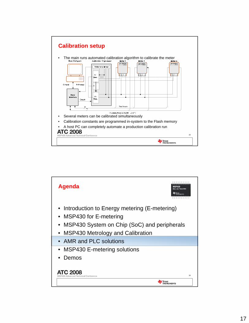
Calibration setup
• The main runs automated calibration algorithm to calibrate the meter
• Several meters can be calibrated simultaneously• Calibration constants are programmed in-system to the Flash memory• A host PC can completely automate a production calibration run
34
Agenda
• Introduction to Energy metering (E-metering)• MSP430 for E-metering• MSP430 System on Chip (SoC) and peripherals• MSP430 Metrology and Calibration• AMR and PLC solutions• MSP430 E-metering solutions• Demos
18
35
Smart Meters?
• Meters that have some sort of communication capability • Communication channels for AMR could be PLC, RF GSM/GPRS or
M-BUS• Advantages for the consumer:
– Clear and consumption-based invoicing– Failure information/handling– New tariff possibilities, load management included
• Advantages for the energy companies:– Network optimization– Automated metering and invoice processes– Bad payers process (pre-paid services)– Immediate detection of tampering
36
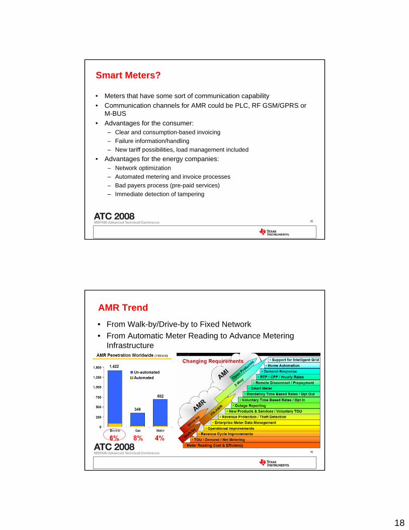
AMR Trend• From Walk-by/Drive-by to Fixed Network • From Automatic Meter Reading to Advance Metering
Infrastructure
19
37
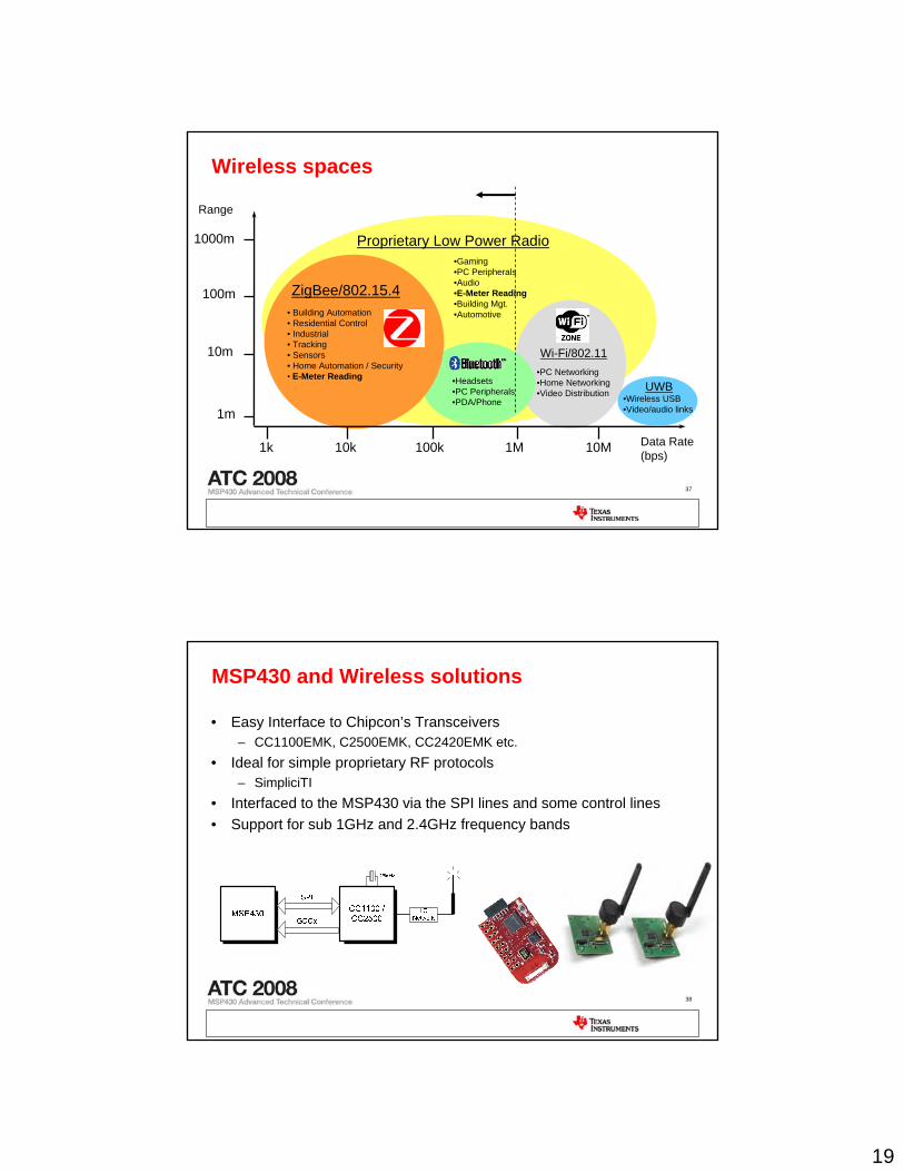
Wireless spaces
1000m
•Headsets•PC Peripherals•PDA/Phone
• Building Automation• Residential Control • Industrial • Tracking • Sensors• Home Automation / Security• E-Meter Reading
Data Rate (bps)
100k 1M 10M10k1k
Range
100m
10m
1m
ZigBee/802.15.4
•PC Networking•Home Networking•Video Distribution
Wi-Fi/802.11
Proprietary Low Power Radio•Gaming•PC Peripherals•Audio•E-Meter Reading•Building Mgt.•Automotive
UWB•Wireless USB•Video/audio links
38
MSP430 and Wireless solutions
• Easy Interface to Chipcon’s Transceivers– CC1100EMK, C2500EMK, CC2420EMK etc.
• Ideal for simple proprietary RF protocols– SimpliciTI
• Interfaced to the MSP430 via the SPI lines and some control lines• Support for sub 1GHz and 2.4GHz frequency bands
20
39
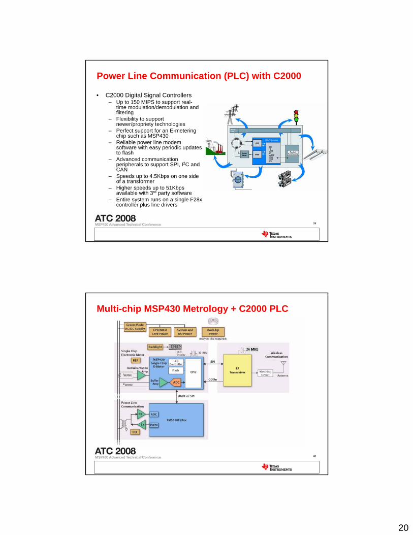
Power Line Communication (PLC) with C2000
• C2000 Digital Signal Controllers – Up to 150 MIPS to support real-
time modulation/demodulation and filtering
– Flexibility to support newer/propriety technologies
– Perfect support for an E-metering chip such as MSP430
– Reliable power line modem software with easy periodic updates to flash
– Advanced communication peripherals to support SPI, I2C and CAN
– Speeds up to 4.5Kbps on one side of a transformer
– Higher speeds up to 51Kbps available with 3rd party software
– Entire system runs on a single F28x controller plus line drivers
40
Multi-chip MSP430 Metrology + C2000 PLC
21
41
Agenda
• Introduction to Energy metering (E-metering)• MSP430 for E-metering• MSP430 System on Chip (SoC) and peripherals• MSP430 Metrology and Calibration• AMR and PLC solutions• MSP430 E-metering solutions• Demos
42
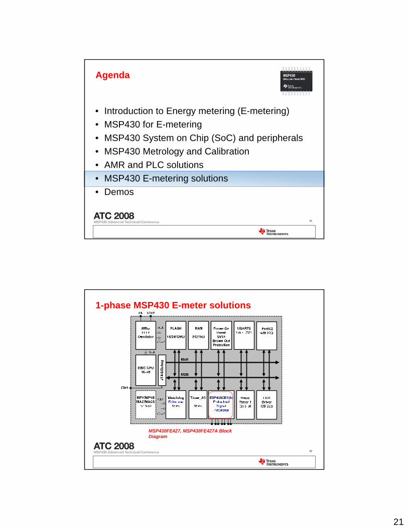
1-phase MSP430 E-meter solutions
MSP430FE427, MSP430FE427A Block Diagram
22
43
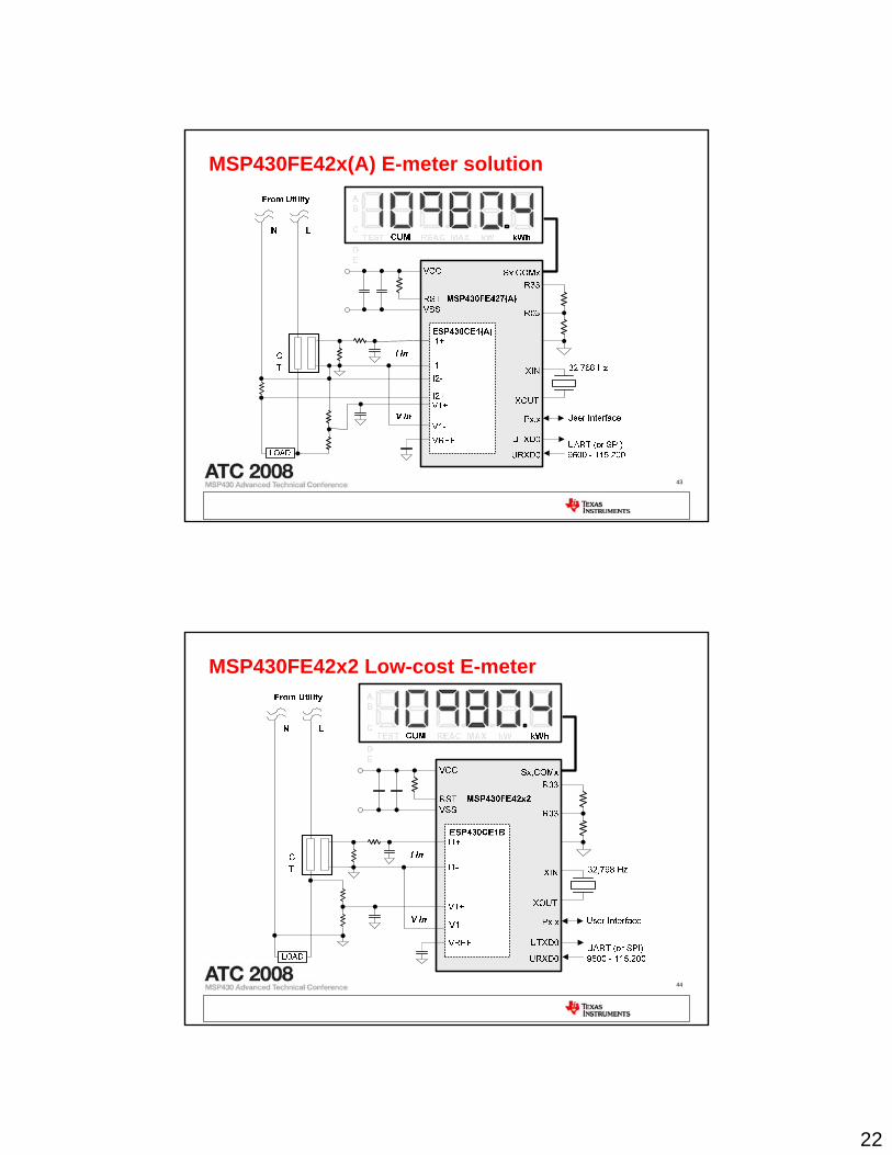
MSP430FE42x(A) E-meter solution
44
MSP430FE42x2 Low-cost E-meter
23
45
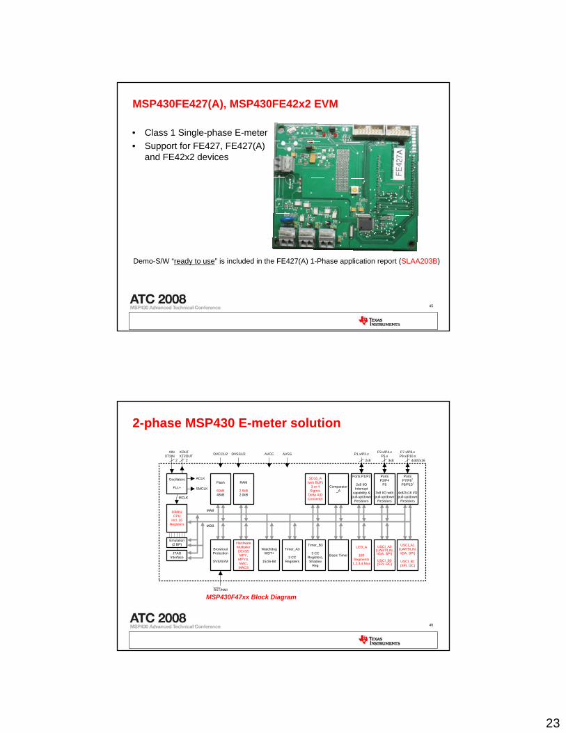
MSP430FE427(A), MSP430FE42x2 EVM
• Class 1 Single-phase E-meter• Support for FE427, FE427(A)
and FE42x2 devices
Demo-S/W “ready to use” is included in the FE427(A) 1-Phase application report (SLAA203B)
46
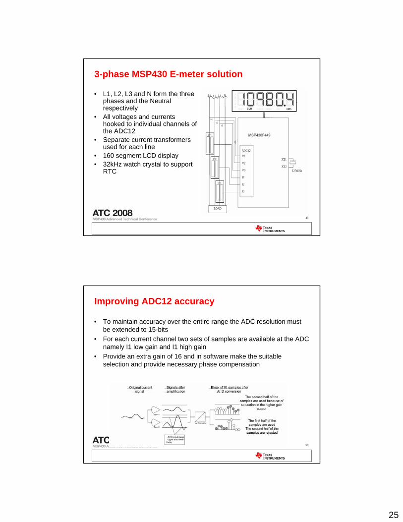
2-phase MSP430 E-meter solution
P3.x/P4.xP5.x
3x8
P7.x/P8.xP9.x/P10.x
4x8/2x16
Oscillators
FLL+RAM
2.5kB2.0kB
Brownout Protection
SVS/SVM
RST/NMI
DVCC1/2 DVSS1/2
MCLK
WatchdogWDT+
15/16-Bit
Timer_A3
3 CC Registers
16MHzCPU
incl. 16 Registers
Emulation(2 BP)
XOUTXT2OUT
Basic TimerJTAGInterface
LCD_A
160 Segments
1,2,3,4 Mux
USCI_A0(UART/LIN,IrDA, SPI)
USCI_B0(SPI, I2C)
Comparator_A
Flash
60kB48kB
Hardware Multiplier(32x32)MPY,
MPYS, MAC, MACS
Timer_B3
3 CC Registers, Shadow
Reg
USCI_A1(UART/LIN,IrDA, SPI)
USCI_B1(SPI, I2C)
AVCC AVSS P1.x/P2.x
2x8
XINXT2IN
SMCLK
ACLK
MDB
MAB
SD16_A(w/o BUF)
3 or 4Sigma-
Delta A/D Converter
22
Ports P1/P2
2x8 I/O Interrupt
capability & pull-up/down
Resistors
PortsP3/P4
P5
3x8 I/O with pull-up/down
Resistors
PortsP7/P8†
P9/P10†
4x8/2x16 I/Opull-up/down
Resistors
MSP430F47xx Block Diagram

24
47
MSP430F47x4 E-meter solution
48
MSP430F4794 EVM
• Class 1 single-phase E-meter• Comprehensive easy tool for
energy measurement• RS-232 based GUI for metrics
and calibration• Complete HW and SW
available for customers 2H of 08
25
49
3-phase MSP430 E-meter solution
• L1, L2, L3 and N form the three phases and the Neutral respectively
• All voltages and currents hooked to individual channels of the ADC12
• Separate current transformers used for each line
• 160 segment LCD display• 32kHz watch crystal to support
RTC
50
Improving ADC12 accuracy
• To maintain accuracy over the entire range the ADC resolution must be extended to 15-bits
• For each current channel two sets of samples are available at the ADC namely I1 low gain and I1 high gain
• Provide an extra gain of 16 and in software make the suitable selection and provide necessary phase compensation
26
51
Software implementation-ADC12
• Analog inputs– ADC12MEM0 I1 low gain– ADC12MEM1 I1 high gain– ADC12MEM2 V1– ADC12MEM3 I2 low gain– ADC12MEM4 I2 high gain– ADC12MEM5 V2– ADC12MEM6 I3 low gain– ADC12MEM7 I3 high gain– ADC12MEM8 V3
• All channels sequentially sampled with one trigger• Sampling triggered at 3.2768 ksps with Timer_A using ACLK
52
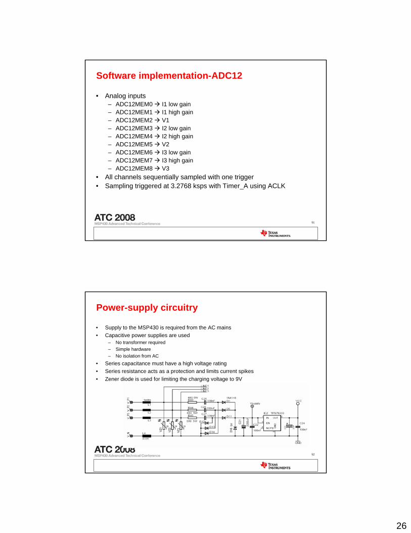
Power-supply circuitry
• Supply to the MSP430 is required from the AC mains• Capacitive power supplies are used
– No transformer required– Simple hardware– No isolation from AC
• Series capacitance must have a high voltage rating• Series resistance acts as a protection and limits current spikes• Zener diode is used for limiting the charging voltage to 9V
27
53
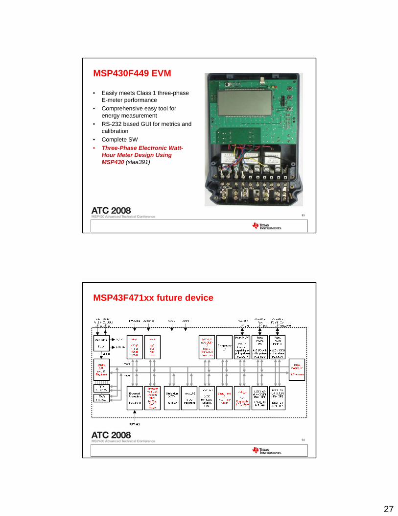
MSP430F449 EVM
• Easily meets Class 1 three-phase E-meter performance
• Comprehensive easy tool for energy measurement
• RS-232 based GUI for metrics and calibration
• Complete SW• Three-Phase Electronic Watt-
Hour Meter Design Using MSP430 (slaa391)
54
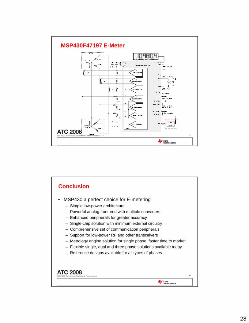
MSP43F471xx future device
28
55
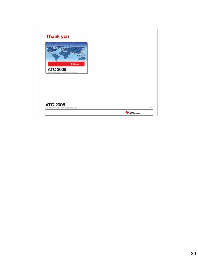
MSP430F47197 E-Meter
56
Conclusion
• MSP430 a perfect choice for E-metering– Simple low-power architecture– Powerful analog front-end with multiple converters– Enhanced peripherals for greater accuracy– Single-chip solution with minimum external circuitry– Comprehensive set of communication peripherals – Support for low-power RF and other transceivers– Metrology engine solution for single phase, faster time to market– Flexible single, dual and three phase solutions available today– Reference designs available for all types of phases
29
57
Thank you