msi-monterey smart b - · pdf filethe monterey smart ventilator is a medical device designed...
TRANSCRIPT

Código do Manual: 204010134 - 1 - REV B
Service Manual
MONTEREY SMART VENTILATOR
Manual Code: 204010134 Revision: B (OCT/2002)

Código do Manual: 204010134 - 2 - REV B
DEFINITIONS
Warning
Warns the user as to the possibility of injury, death or other serious adverse reactions associated with the use or misuse of the equipment.
Attention
Warns the user about possible problems with the equipment, associated to its use or misuse, such as device malfunction or failure, damage to the equipment or damage to third party property.
NOTE:
Emphasizes important information

Código do Manual: 204010134 - 3 - REV B
THE COMPANY
K. TAKAOKA is a company that for more than 40 years has been dedicated to the hospital equipment industry, always in close cooperation with physicians. Working specifically in the areas of Anesthesia Machines, Pulmonary Ventilators, Monitoring and Oxygen therapy, K. TAKAOKA is proud of its leading position in the market and presents an extensive range of products. With one of its priorities being continuing investments in the research and development of new ideas and solutions, K. TAKAOKA has distinguished itself through the constant introduction of technological advances and industrial innovations in its product line. This places K. TAKAOKA on equal footing with its principal national and international competitors. Using sophisticated equipment, K. TAKAOKA designs and manufactures most of the components for its machines, which is why these items undergo such strict quality control. The company is also concerned with supplying top quality customer assistance through its Sales and Technical Assistance departments. With representatives throughout Brazil and also having a presence in the international market, K. TAKAOKA has earned its customers’ confidence over the years, through its high standards of quality and the great efficiency of its products and services.

Código do Manual: 204010134 - 4 - REV B
CONTENTS
1 IMPORTANT INFORMATION .......................................................................... 5 2 GENERAL DESCRIPTION............................................................................... 8 3 OPERATING PRINCIPLE .............................................................................. 10
Pneumatic Schematic .................................................................................... 10 Flow Sensor................................................................................................... 12 Magnetic Expiratory Valve ............................................................................. 13 Servo Valve ................................................................................................... 15 Overpressure Valve ....................................................................................... 17
4 COMPONENT IDENTIFICATION .................................................................. 18 External Components .................................................................................... 19 Ventilator ....................................................................................................... 21 Central box .................................................................................................... 22 Regulation valves .......................................................................................... 24 Proportional valves ........................................................................................ 25 Transducer board .......................................................................................... 26 Front panel .................................................................................................... 27 Rear panel ..................................................................................................... 28 Right side....................................................................................................... 29 Left side ......................................................................................................... 30 Exhalation Valve............................................................................................ 31
5 ELECTRONIC DESCRIPTION....................................................................... 33 Power Supply System.................................................................................... 34 Bargraph Board ............................................................................................. 38 Ventilator Control Board ................................................................................ 40 Expiratory valve control circuit ....................................................................... 43 Servo-valve control circuit.............................................................................. 45 Patient Flow Amplifier Circuit ......................................................................... 48 Internal Flow Amplifier Circuit ........................................................................ 49 Pressure sensor amplifier circuit.................................................................... 51
6 CABLE AND BOARD CONNECTION SCHEMATIC ...................................... 52 7 CHECKING THE BASE.................................................................................. 53 8 CHECKING THE POWER SUPPLY .............................................................. 56 9 ELECTRONIC ADJUSTMENT ....................................................................... 57 10 VERIFYING OPERATION.............................................................................. 64 11 ELECTRIC AND PNEUMATIC SUPPLY........................................................ 78 12 REVISION PROGRAM................................................................................... 80 13 PREVENTIVE MAINTENANCE ..................................................................... 82 14 REPRESENTANTES.......................................................................................85 15 ASISTENCIA TÉCNICA...................................................................................87

Código do Manual: 204010134 - 5 - REV B
1 IMPORTANT INFORMATION The MONTEREY SMART Ventilator is a medical device designed to combine state-of-the-art technology with extreme ease of use. Only qualified and trained professionals should operate it. Qualified TAKAOKA professionals should perform all preventive or corrective maintenance services for . Carefully review all warnings and recommendations in this manual. Ventilation After starting ventilation check that the ventilation parameters indicated on the screen are correct.
Check the proper setting of all alarm limits.
To ensure all condensed water in the breathing circuit flows back to the drains and does not reach the patient, the tube support must be placed near the Y-shaped connector and placed in a position below the patient's mouth level.
To prevent accidental disconnection or gas leakage in the breathing circuit, make sure all connections are tightly connected. Tightly close the threaded KT-6060 Heated Humidifier cap.
Frequently check the endotracheal tube connection integrity.
Flow Sensor Always connect the REQUESTED flow sensor.
Only the flow sensor supplied by TAKAOKA for the MONTEREY SMART Ventilator may be used.
When using the Ventilator, check that the flow sensor is clean at least every
2 hours.

Código do Manual: 204010134 - 6 - REV B
Electric Supply and Internal Battery Only connect the power cable to an electric outlet that is properly grounded and approved for hospital use and to a power supply which complies with the ABNT NBR 13534 norm - "Instalações elétricas em estabelecimentos assistenciais de saúde - Requisitos de segurança" (Electrical installations in health care establishments – Safety requirements”). The 3 prong female outlet should be a 3-pin Nema 5-15P type outlet.
Keep the internal battery charged at all times so the Ventilator keeps working even during a power failure. To do this, the Ventilator must be connected to the distribution network, even when it is switched off.
Recharge the battery after using the Ventilator during a power failure so it is ready for the next use.
Fully recharge the battery when the Ventilator is left unused and disconnected from an electric power source for more than 20 (twenty) days.
The Heated Humidifier will not run off the Ventilator's internal battery.
If the Ventilator’s internal battery is powering it and the low battery alarm is activated, the Ventilator must be connected immediately to an electric power source.
Miscellaneous The usage of this service manual only applies to the maintenance of MONTEREY SMART ventilators with software release 1.00 or above.
The Ventilator must be serviced by an authorized TAKAOKA technician at least every six months.
Do not use the Ventilator if the self-test detects any abnormality. Resolve the detected problem.
Make sure the Ventilator is correctly set up and that the alarms are properly set before using the equipment.
Do not exceed the maximum amount of medication indicated on the reservoir when filling the Nebulizer container.
Do not press any key using surgical instruments or tools. Only use your fingertips to press the keys. Hard or sharp objects may damage them.

Código do Manual: 204010134 - 7 - REV B
Set up an appropriate cleaning and sterilization routine for the Ventilator components.
Constantly check that the digital inspiratory pressure gauge or the P x t graph indicate the proper values.
Keep the patient under constant observation. Frequently watch the patient's pulmonary expansion and free exhalation.
Read this Service Manual very carefully in order to use the equipment correctly and to obtain the greatest gain from all its features.
Also read the Instruction Manual for the Heated Humidifier KT-6060 that comes with the MONTEREY SMART Ventilator.
Only TAKAOKA’S specialized and authorized technicians should perform any repair on the Ventilator.
Service (Preventive and corrective maintenance) Only a technician trained and authorized by TAKAOKA may perform any internal service on the MONTEREY SMART Ventilator. This Service Manual does not replace proper technician training.
This Service Manual was designed for technicians familiar with the operating parts and controls of the equipment. The Operation Manual for the MONTEREY SMART Ventilator must be read carefully.
Only use original TAKAOKA replacement parts. Using non-original parts could be hazardous for the patient.
TAKAOKA product’s technical features are subject to change without prior notice due to their constant technological development.

Código do Manual: 204010134 - 8 - REV B
2 GENERAL DESCRIPTION The MONTEREY SMART Ventilator is an electronic respirator designed for use in cases of respiratory insufficiency in the Intensive Care Unit. It can be used either for invasive or non-invasive ventilation. The table below shows the ventilation modes available with the MONTEREY SMART Ventilator. The modes that require the patient's inspiratory effort to trigger breathing cycles have a safety system against apnea, which automatically switches to another backup mode, except for the CPAP mode.

Código do Manual: 204010134 - 9 - REV B
Item Mode Description Backup Ventilation
1 VCV Volume-controlled ventilation ---
2 PCV Pressure-controlled ventilation ---
3 PCV/AV® Assured ventilation volume by pressure control ---
4 SIMV/V Synchronized intermittent mandatory ventilation with volume control
IMV (non-synchronized)
5 SIMV/P® Synchronized intermittent mandatory ventilation with pressure control
IMV (non-
synchronized)
6 BIPV® Spontaneous ventilation with two pressure levels ---
7 CPAP Ventilation with continuous positive airway pressure
No backup ventilation
8 PSV Ventilation with continuous positive airway pressure and support pressure
PCV

Código do Manual: 204010134 - 10 - REV B
3 OPERATING PRINCIPLE Pneumatic Schematic Figure 3.1 shows the internal pneumatic schematic of the MONTEREY Ventilator, which is described below. Oxygen (O2) and compressed air enter the MONTEREY SMART Ventilator by means of their respective threaded connectors, and then follow parallel paths until they mix immediately before the breathing circuit outlet. Near each gas inlet there is a low oxygen or compressed air pressure alarm sensor. The pressure of each gas is reduced by a pressure regulating valve, where there is also a control to calibrate the set pressure. Both gases flow through their electronically controlled servo valves, which constantly supply the exact amount to match the oxygen flow and concentration adjustments for ventilation. The oxygen and compressed air flows are mixed and released into the breathing circuit. The inspiratory pressure control is performed by the electromagnetic expiratory valve, which is controlled by an electronic microprocessed system. Attention
The internal MONTEREY SMART Ventilator components are interconnected by means of standardized tubes. Some internal tubes of the MONTEREY SMART Ventilator are spiral-shaped for better accommodation and maintenance. Use only the original tubes supplied by TAKAOKA.

Código do Manual: 204010134 - 11 - REV B
Figure 3.1: MONTEREY SMART ventilator pneumatic schematic

Código do Manual: 204010134 - 12 - REV B
Flow Sensor The MONTEREY SMART Ventilator has two flow sensors (Figure 3.2) to measure the flow and volume of gases. One is internal and the other, which is attached to the breathing system, is external.. Each "differential pressure" flow sensor is composed of an adapter with two conical connections, inside of which there is a resistance to flow passage. Two lateral tubes carry the inlet and outlet pressure signals from the flow sensor to a differential pressure transducer located inside the Ventilator cabinet. The value of the inhaled or exhaled flow is constantly measured in terms of the pressure difference detected by the sensor. The flow sensor also detects the Ventilator’s cycling events.
Fluxo
∆P
∆P
Fluxo Figure 3.2: Flow Sensor
Flow
Flow

Código do Manual: 204010134 - 13 - REV B
Magnetic Expiratory Valve Figure 3.3 shows a cross-section of the electromagnetic valve construction, which has a very simple and safe operating principle. The diaphragm controls the flow passage and isolates the inner part of the valve to prevent its contamination. A pin that moves along with the mobile coil that moves inside a magnet performs diaphragm control. The diaphragm closing force depends on the electric current applied to the coil (Figure 3.4) and it is electronically controlled by means of a feedback system.
Figure 3.3: Magnetic Valve
FLOW
MAGNET
MOBILE COIL
PIN
DIAPHRAGM

Código do Manual: 204010134 - 14 - REV B
I = 0I > 0
Figure 3.4: Magnetic valve operation. The magnetic valve is normally open, allowing free flow passage in case there is no electric current. The controlled pressure is directly proportional to the applied current in Figure 3.5.
Força ou Pressão
Corrente (mA) Figure 3.5: Force according to the applied current
Pressure or force
Current

Código do Manual: 204010134 - 15 - REV B
Servo Valve Figure 3.6 shows a cross-section of the flow servo valve construction. This valve is used to control the flow of oxygen and air. The flow servo valve is normally closed, that is, it does not release flow as long as there is no applied current in its electric terminals due to the spring’s action, which holds down the piston and obstructs gas passage. When there is an applied current, the coil exerts sufficient pressure on the piston, which in turn compresses the spring, thus allowing gas passage. The outlet flow is proportional to the applied current, and therefore this servo valve is often referred to as a proportional valve.
I = 0 I > 0
Figure 3.6: Operating principle of the flow servo valve

Código do Manual: 204010134 - 16 - REV B
Regulating Valve This valve allows outlet pressure regulation. Its operation is very simple. The spring (1) exerts force on the diaphragm (2) that is equal to the existing pressure at the outlet multiplied by the diaphragm’s area. The piston (3) moves downwards or upwards as the outlet pressure increases or decreases, thus allowing passage from the inlet to the outlet. Therefore, if the outlet pressure decreases, the spring (1) moves the diaphragm (2), which in turn moves the piston (3), thus allowing the passage from inlet to outlet. On the other hand, if the outlet pressure increases, the diaphragm (2) pushes the spring (1) and the piston (3) moves upwards due to the force exerted by the spring (4), thus obstructing the passage.
Figure 3.7: Regulating Valve
1
2
3
4 Input Input
Output Output
Código do Manual: 204010134 - 17 - REV B
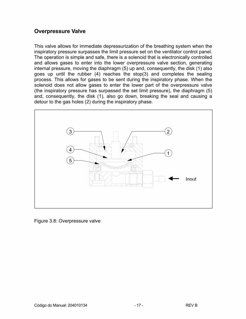
Overpressure Valve This valve allows for immediate depressurization of the breathing system when the inspiratory pressure surpasses the limit pressure set on the ventilator control panel. The operation is simple and safe, there is a solenoid that is electronically controlled and allows gases to enter into the lower overpressure valve section, generating internal pressure, moving the diaphragm (5) up and, consequently, the disk (1) also goes up until the rubber (4) reaches the stop(3) and completes the sealing process. This allows for gases to be sent during the inspiratory phase. When the solenoid does not allow gases to enter the lower part of the overpressure valve (the inspiratory pressure has surpassed the set limit pressure), the diaphragm (5) and, consequently, the disk (1), also go down, breaking the seal and causing a detour to the gas holes (2) during the inspiratory phase.
Figure 3.8: Overpressure valve
1
23
4
5
Input

Código do Manual: 204010134 - 18 - REV B
4 COMPONENT IDENTIFICATION
This chapter presents some drawings of the internal part of the MONTEREY SMART Ventilator with the corresponding material lists. Use these drawings to locate the Ventilator's internal components as well as a reference to the assembly and maintenance procedures.
Código do Manual: 204010134 - 19 - REV B
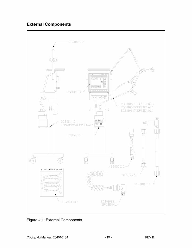
External Components
CICLO
K. TAKAOKAINDÚSTRIA E COMÉRCIO LTDA. INDÚSTRIA E COMÉRCIO LTDA.
K. TAKAOKA K. TAKAOKAINDÚSTRIA E COMÉRCIO LTDA.
Figure 4.1: External Components
Código do Manual: 204010134 - 20 - REV B
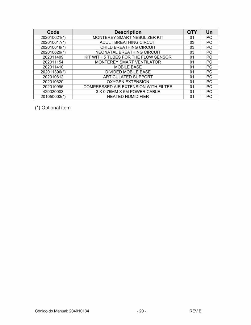
Code Description QTY Un 202010621(*) MONTEREY SMART NEBULIZER KIT 01 PC 202010617(*) ADULT BREATHING CIRCUIT 03 PC 202010618(*) CHILD BREATHING CIRCUIT 03 PC 202010629(*) NEONATAL BREATHING CIRCUIT 03 PC 202011409 KIT WITH 5 TUBES FOR THE FLOW SENSOR 01 PC 202011154 MONTEREY SMART VENTILATOR 01 PC 202011410 MOBILE BASE 01 PC
202011396(*) DIVIDED MOBILE BASE 01 PC 202010612 ARTICULATED SUPPORT 01 PC 202010620 OXYGEN EXTENSION 01 PC 202010996 COMPRESSED AIR EXTENSION WITH FILTER 01 PC 429020003 3 X 0.75MM X 5M POWER CABLE 01 PC
201050003(*) HEATED HUMIDIFIER 01 PC (*) Optional item

Código do Manual: 204010134 - 21 - REV B
Ventilator
CICLO
Figure 4.2: Ventilator
Code Description QTY Un 202011194 MONTEREY VENTILATOR REAR CAP 1 PC 202010596 MONTEREY SMART VENTILATOR LOWER CAP 1 PC 202010597 MONTEREY SMART VENTILATOR RIGHT SIDE 1 PC 202010598 MONTEREY SMART VENTILATOR LEFT SIDE 1 PC 203011808 VENTILATOR STRAP 1 PC 202010623 MONTEREY SMART VENTILATOR SHELF SET 1 PC 202011155 CENTRAL BOX 1 PC 202011156 MONTEREY SMART VENTILATOR FRONT PANEL 1 PC 203060237 MONTEREY SMART VENTILATOR SMALL RIGHT
FRAME SET 1 PC
203060238 MONTEREY SMART VENTILATOR SMALL LEFT FRAME SET 1 PC
302030019 8X3.3X1.06 FLAT BRASS WASHER 4 PC 310020001 FLAT HEAD PHS SCREW M3X12 8 PC 314020013 PAN HEAD PHS SCREW M3X10 2 PC 314020014 PAN HEAD PHS SCREW M3X20 8 PC 314020015 PAN HEAD PHS SCREW M3X6 4 PC 317020051 BULGED HEAD PHS SCREW M3X16 4 PC

Código do Manual: 204010134 - 22 - REV B
Central box
Figure 4.3: Central box
Code Description QTY Un 202010025 ANTI-ASPHYXIA VALVE 1 PC 202010145 EXPIRATORY VALVE 1 PC 202011158 OVERPRESSURE VALVE 1 PC 202011168 CENTRAL BOX REAR COVER 1 PC 202011240 SUPPORT FOR THE PCI 1 PC 202020092 CENTRAL CASE SET 1 PC 203010025 NOZZLE - INT DIAM. 1.0 MM 1 PC 203010026 NOZZLE - INT DIAM. 1.5 MM 2 PC 203010031 P/ T NOZZLE 2 PC 203010045 NOZZLE - INT DIAM. 4.0 MM THREAD M6 2 PC 203010593 MONTEREY SMART VENTILATOR CONNECTION 1 PC 203010611 MONTEREY'S MACHINED WASHER - 7/8”X16MMX3MM 1 PC 203010618 THREADED CONNECTION 5/8”X26 1 PC 203010762 NEBULIZER NOZZLE 1 PC 203010878 MONTEREY'S NOZZLE 2 PC 203011595 LOWER BLOCK 1 PC 203030274 ADULT FLOW SENSOR 1 PC 203030569 MONTEREY SMART VENTILATOR TIE 1 PC 316030025 HEX ALLEN GRUB SCREW M6 1 PC 320010040 HEX NUT 3/8”XM6 1 PC 429090016 ELECTROMAGNETIC VALVE CABLE 1 PC 203011131 VALVE CONNECTION 1 PC

Código do Manual: 204010134 - 23 - REV B
314020010 PAN HEAD SCREW W/CROSS SLOT M3X0, 5PX14MM 2 PC 202011355 OVERPRESSURE VALVE FEEDING NOZZLE 1 PC 203060031 LUER COVER 1 PC 203011287 VENTILATION NOZZLE MONTEREY SMART 3 PC 117060021 BLUE PVC TUBE 7, 5X1, 75 MM 117060020 CRYSTAL PVC TUBE 7, 5X1, 75 MM 117060028 CRYSTAL FLEXIBLE TUBE 3X1.6 MM
Código do Manual: 204010134 - 24 - REV B
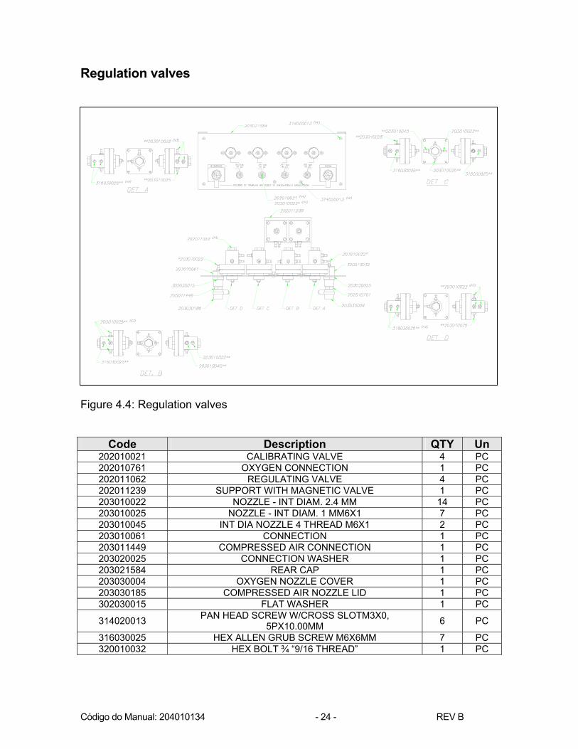
Regulation valves
Figure 4.4: Regulation valves
Code Description QTY Un 202010021 CALIBRATING VALVE 4 PC 202010761 OXYGEN CONNECTION 1 PC 202011062 REGULATING VALVE 4 PC 202011239 SUPPORT WITH MAGNETIC VALVE 1 PC 203010022 NOZZLE - INT DIAM. 2.4 MM 14 PC 203010025 NOZZLE - INT DIAM. 1 MM6X1 7 PC 203010045 INT DIA NOZZLE 4 THREAD M6X1 2 PC 203010061 CONNECTION 1 PC 203011449 COMPRESSED AIR CONNECTION 1 PC 203020025 CONNECTION WASHER 1 PC 203021584 REAR CAP 1 PC 203030004 OXYGEN NOZZLE COVER 1 PC 203030185 COMPRESSED AIR NOZZLE LID 1 PC 302030015 FLAT WASHER 1 PC 314020013 PAN HEAD SCREW W/CROSS SLOTM3X0,
5PX10.00MM 6 PC 316030025 HEX ALLEN GRUB SCREW M6X6MM 7 PC 320010032 HEX BOLT ¾ “9/16 THREAD” 1 PC

Código do Manual: 204010134 - 25 - REV B
Proportional valves
Figure 4.5: Proportional valves
Code Description QTY Um 202010609 PROPORTIONAL VALVE 2 PC 203021625 PROPORTIONAL VALVE SUPPORT 1 PC 314020022 PAN HEAD PHS SCREW M3X10 4 PC

Código do Manual: 204010134 - 26 - REV B
Transducer board
Figure 4.6: Transducer board
Code Description QTY Um 203021647 BOARD SUPPORT 1 PC 320010004 HEX BOLT 1/8”X40F 4 PC 445010129 MONTEREY SMART PCI TRANSDUCER 1 PC

Código do Manual: 204010134 - 27 - REV B
Front panel
CICLO
Figure 4.7: Front panel
Code Description QTY UMI 202020401 MONTEREY SMART FRONT PANEL 1 PC 203020607 MONTEREY SMART VENTILATOR DISC 1 PC 203020837 POLYETHYLENE TUBE DIAM ¼” X 10.5 3 PC 203020847 POLYETHYLENE TUBE 6 PC 203030009 BUSHING 2 PC 203060352 MEMBRANE KEYBOARD 1 PC 302030005 FLAT WASHER 3 PC 320001004 HEX THREADED NUT 1/8" X 40 WIRES (BSW) 6 PC 429090101 BARGRAPH CABLE 1 PC 429090102 LED CABLE 2 PC 429090173 CONTROL CABLE 1 PC 435010014 LCD DISPLAY 240X128MM 1 PC 445010143 MONTEREY'S ASSEMBLED PCI BARGRAPH 1 PC
445000060-04 MONTEREY SMART CONTROL PCI 1 PC

Código do Manual: 204010134 - 28 - REV B
Rear panel
Figure 4.8: Rear panel
Code Description QTY Un 203020609 MONTEREY SMART BATTERY SUPPORT 1 PC 203020613 MONTEREY SMART VENTILATOR LOCK 2 PC 203100284 MONTEREY SMART REAR LID 1 PC 203030127 SUPPORT 2 PC 203060084 MODEL-SERIES ENGRAVED PLATE 1 PC 203060136 FOAM STRIP 1 PC 203060266 PLSKLIP P3 HELLERMAN BRACKET 1 PC 302010002 PRESSURE WASHER ¼ “X10.5X1.5 4 PC 314020005 PAN HEAD PHS SCREW M2X8 2 PC 314020013 PAN HEAD SCREW W/CROSS SLOT M3X0, 5PX10MM 3 PC 317030051 ALLEN BULGED HEAD SCREW 1/4X3/8" 4 PC 320010004 HEX THREADED NUT 1/8" X 40 WIRES (BSW) 2 PC 320010016 HEX NUT M2X2MM 2 PC 320010028 ¼”X40F THREADED HEX NUT 2 PC 421010003 FUSE-HOLDER 2 PC 429060005 FLEXIBLE WIRE 1 PC 429090004 BATTERY CABLE 1 PC 429090005 NETWORK/SOURCE CABLE 1 PC 429090012 RS 232 CABLE 1 PC 429090018 ON/OFF KEY CABLE 1 PC 429090053 GROUNDING CABLE 1 PC 429090076 SOURCE/FUSE CABLE 1 PC 429090077 EXTERNAL SOURCE CABLE 1 PC 429090078 TAP/FUSE CABLE 1 PC 430010005 RF-S1320 CONNECTOR 1 PC 437010003 12V 2.2AH RECHARGEABLE BATTERY 1 PC 450020002 ELECTRIC TAP REF S-16 57M 1 PC

Código do Manual: 204010134 - 29 - REV B
Right side
Figure 4.9: Right side
Code Description QTY Un 202020098 RIGHT SIDE SET 1 PC 203030127 SUPPORT 1 PC 302010002 PRESSURE WASHER ¼ “X10.5X1.5 2 PC 317030051 ALLEN BULGED HEAD SCREW 1/4X3/8" 2 PC

Código do Manual: 204010134 - 30 - REV B
Left side
Figure 4.10: Left side
Code Description QTY Un 202020099 LEFT SIDE SET 1 PC 203030127 SUPPORT 1 PC 302010002 PRESSURE WASHER ¼ “X10.5X1.5 2 PC 317030051 ALLEN BULGED HEAD SCREW 1/4X3/8" 2 PC 429090171 LOUDSPEAKER CABLE AND POTENTIOMETER 1 PC
Código do Manual: 204010134 - 31 - REV B
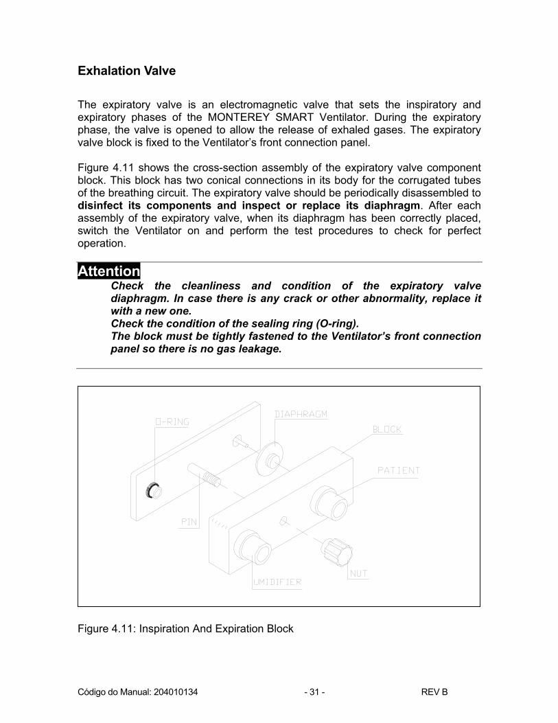
Exhalation Valve The expiratory valve is an electromagnetic valve that sets the inspiratory and expiratory phases of the MONTEREY SMART Ventilator. During the expiratory phase, the valve is opened to allow the release of exhaled gases. The expiratory valve block is fixed to the Ventilator’s front connection panel. Figure 4.11 shows the cross-section assembly of the expiratory valve component block. This block has two conical connections in its body for the corrugated tubes of the breathing circuit. The expiratory valve should be periodically disassembled to disinfect its components and inspect or replace its diaphragm. After each assembly of the expiratory valve, when its diaphragm has been correctly placed, switch the Ventilator on and perform the test procedures to check for perfect operation. Attention
Check the cleanliness and condition of the expiratory valve diaphragm. In case there is any crack or other abnormality, replace it with a new one. Check the condition of the sealing ring (O-ring). The block must be tightly fastened to the Ventilator’s front connection panel so there is no gas leakage.
Figure 4.11: Inspiration And Expiration Block

Código do Manual: 204010134 - 32 - REV B
Figure 4.12: Inspiratory and Expiratory Block Components
Code Description QTY Un 202010239 MAGNETIC VALVE 1 PC 203010331 NOZZLE INT. DIA 9/16”X26F – EXT DIA 9/16” 1 PC 203010348 NUT 1 PC 203010615 VALVE BODY 1 PC 203010617 THREADED PIN 5/16”X18F M8X1.25P 1 PC 203010619 HEX BOLT ½ “- EXT DIA 14MM 1 PC 203020084 SEALING WASHER 1 PC 203020622 EXPIRATORY VALVE SUPPORT 1 PC 203030330 EXPIRATORY VALVE BASE 1 PC 203030331 EXPIRATORY VALVE WASHER 1 PC 203040062 DIAPHRAGM 1 PC 320010047 PRESSABLE BOLT M8 1 PC 303010059 O’RING REF. 2113 V 3206-7B INT DIA 13.94X2.62 THICK 1 PC 320010037 THREADED HEX BOLT M8X1, 25PX6.5 – HEX 13MM 1 PC
Inlay on the piece

Código do Manual: 204010134 - 33 - REV B
5 ELECTRONIC DESCRIPTION A single board that simultaneously monitors and controls the ventilator carries out the electronic control. Figure 5.1, below, represents a simplified block diagram. The following items will provide more details on the system.
Figure 5.1: Block diagram
Código do Manual: 204010134 - 34 - REV B
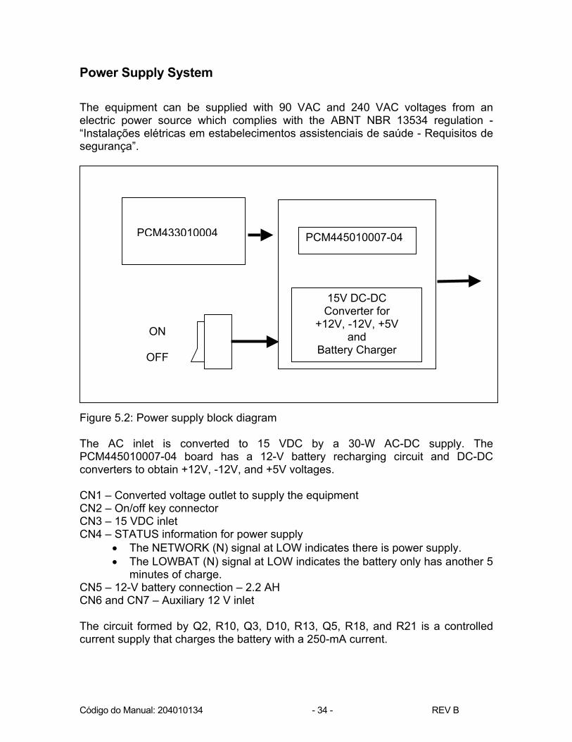
Power Supply System The equipment can be supplied with 90 VAC and 240 VAC voltages from an electric power source which complies with the ABNT NBR 13534 regulation - “Instalações elétricas em estabelecimentos assistenciais de saúde - Requisitos de segurança”. Figure 5.2: Power supply block diagram The AC inlet is converted to 15 VDC by a 30-W AC-DC supply. The PCM445010007-04 board has a 12-V battery recharging circuit and DC-DC converters to obtain +12V, -12V, and +5V voltages. CN1 – Converted voltage outlet to supply the equipment CN2 – On/off key connector CN3 – 15 VDC inlet CN4 – STATUS information for power supply
• The NETWORK (N) signal at LOW indicates there is power supply. • The LOWBAT (N) signal at LOW indicates the battery only has another 5
minutes of charge. CN5 – 12-V battery connection – 2.2 AH CN6 and CN7 – Auxiliary 12 V inlet The circuit formed by Q2, R10, Q3, D10, R13, Q5, R18, and R21 is a controlled current supply that charges the battery with a 250-mA current.
ON
OFF
PCM445010007-04
15V DC-DC Converter for
+12V, -12V, +5V and
Battery Charger
PCM433010004

Código do Manual: 204010134 - 35 - REV B
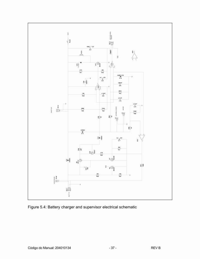
Q5 is also responsible for turning the charging circuit off whenever the battery charge reaches 13.6V. U4:B is a voltage comparer which informs the battery charging status by means of CN4 and controls the general electronic relay. U4:D and Q4 activate a DC-DC converter circuit ON/OFF relay U1 is the DC-DC converter for +12V U2 is the DC-DC converter for -12V U3 is the DC-DC converter for +5V
Código do Manual: 204010134 - 36 - REV B
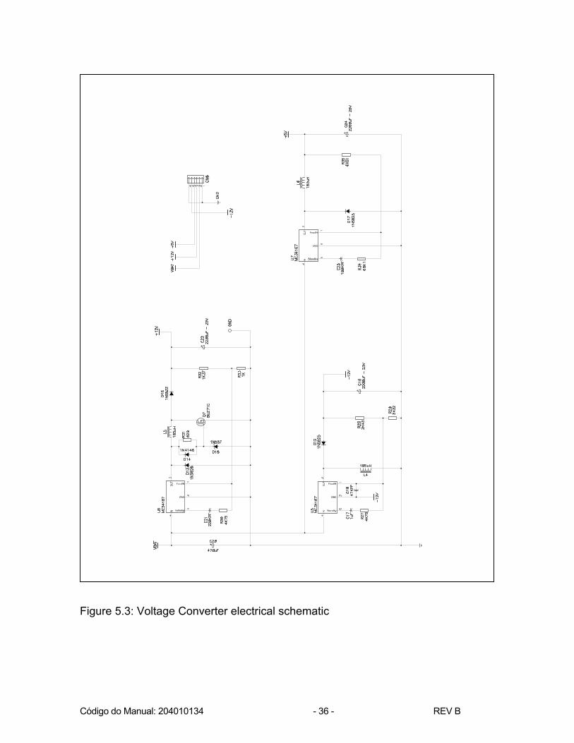
Figure 5.3: Voltage Converter electrical schematic
Código do Manual: 204010134 - 37 - REV B
Figure 5.4: Battery charger and supervisor electrical schematic
EXTE
RN
AL S
OU
RC
E
BATE
RY
ON
/OFF
KEY
LED
NET
WO
RK
INLE
T 15
V
NET
WO
RK
SIN
AL
TEN
SIO
N

Código do Manual: 204010134 - 38 - REV B
Bargraph Board The bargraph operates by means of a timed sweeping process to activate the Leeds. This board has the SW1 Manual Cycle, and the SW2 Reset keys, as well as the LD1 Low Battery, LD3 Electrical Network, and LD2 Reset Leeds. The sweep commands are received from CN2.

Código do Manual: 204010134 - 39 - REV B
Figure 5.5: Bargraph electrical schematic
RED
- BA
TER
Y
GR
EEN
- SI
LEN
CE
GR
EEN
- SI
LEN
CE

Código do Manual: 204010134 - 40 - REV B
Ventilator Control Board The MONTEREY SMART Ventilator control board has a Z84C15 (U2) microprocessor containing timers, a serial communication module, and parallel ports to activate peripheral devices. It has 8KB of RAM memory with real time clock (U4) and 64KB of EPROM memory (U3), an 8-bit A/D converter (U1), and an 8-bit D/A converter (U6). The patient's flow signals, the internal flow and the pressure are converted to a digital format by U1.
• AIN8 – Patient flow x1 • AIN7 – Patient flow x10 • AIN6 – Endotracheal Pressure • AIN5 – Internal Flow x1 • AIN4 – Internal Flow x10
The D/A converter outlets (U6) are used as follows:
• VOUTA – Total flow supplied to the breathing circuit • VOUTB – O2 flow supplied to the breathing circuit • VOUTC – Alarm volume • VOUTD – Breathing circuit pressure
CN1 – DC Power Supply Status CN2 - Pressure measurement of the O2 and compressed air systems CN3 - Membrane Keyboard CN4 – Interface to the 240 x 128 LCD CN5 - Digital serial CN7 - Connection to the Ventilator control display contrast potentiometer CN8 - RS-232C serial outlet – The outlet has special signals for PC connection
with specific software for a graphical display of all simultaneous ventilation curves. (The software and connection systems are optional items). It also has synchronism signals between the two ventilators (ILV). For this to work, a special cable must be used for connection (optional).
CN10 - Loudspeaker – Alarms CN11 – Solenoids CN12 - BARGRAPH CN13 - Magnetic Expiratory Valve CN15 – Air Servo-Valve CN19 - O2 Servo-Valve CN18 – Pressure and flow transducers CN19 - LCD backlight CN20 - +12v, -12v, +5v, VBAT DC Supply

Código do Manual: 204010134 - 41 - REV B
The remaining CNs are not used. U16, U17 and U19 are latches and drivers for the bargraph. U14 and U15 control the valve control circuits on/off procedure. U11:A, Q3, Q4 audio amplifier circuit. The signals: PHASE A, PHASE A, PHASE B, PHASE B, are related to a future installation of a pace motor to control the blender.

Código do Manual: 204010134 - 42 - REV B
CAP
ACIT
OR
ES D
ED
ESAC
OPL
AMEN
TO
TEC
LAD
O
LED
STA
ND
-BY
CO
MU
NIC
AÇÃO
DIG
ITAL
B
Pote
nciô
met
ro d
e C
ontra
ste
SER
IAL
"A" -
RS-
232
Figure 5.6: Monterey Smart control electrical schematic
CO
NTR
AST
POTE
NC
IOM
ETER
REV
ERSE
VID
EO S
ELEC
TIO
N
NET
WO
RK
SEN
SOR
PR
ESSI
ON
KEYB
OAR
D
NET
WO
RK
SEN
SOR
PR
ESSI
ON
Código do Manual: 204010134 - 43 - REV B
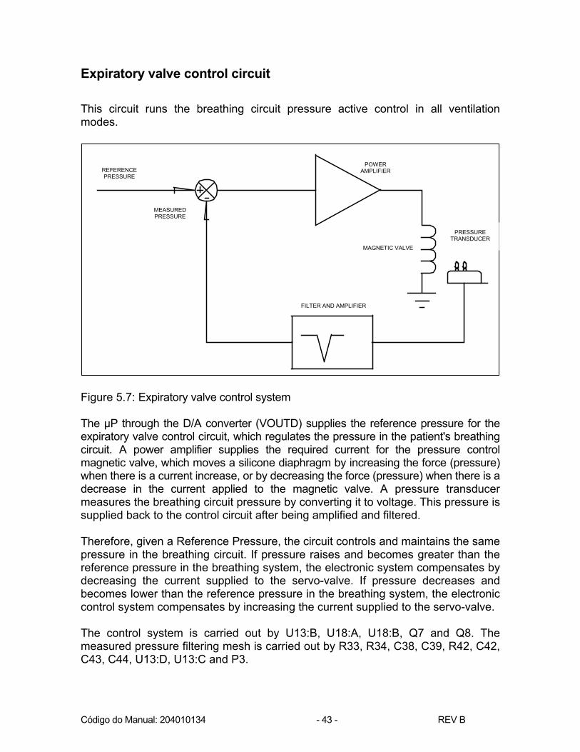
Expiratory valve control circuit This circuit runs the breathing circuit pressure active control in all ventilation modes. Figure 5.7: Expiratory valve control system The µP through the D/A converter (VOUTD) supplies the reference pressure for the expiratory valve control circuit, which regulates the pressure in the patient's breathing circuit. A power amplifier supplies the required current for the pressure control magnetic valve, which moves a silicone diaphragm by increasing the force (pressure) when there is a current increase, or by decreasing the force (pressure) when there is a decrease in the current applied to the magnetic valve. A pressure transducer measures the breathing circuit pressure by converting it to voltage. This pressure is supplied back to the control circuit after being amplified and filtered. Therefore, given a Reference Pressure, the circuit controls and maintains the same pressure in the breathing circuit. If pressure raises and becomes greater than the reference pressure in the breathing system, the electronic system compensates by decreasing the current supplied to the servo-valve. If pressure decreases and becomes lower than the reference pressure in the breathing system, the electronic control system compensates by increasing the current supplied to the servo-valve. The control system is carried out by U13:B, U18:A, U18:B, Q7 and Q8. The measured pressure filtering mesh is carried out by R33, R34, C38, C39, R42, C42, C43, C44, U13:D, U13:C and P3.
Pressão deReferência
PressãoMedida
Amplificador eFiltro
VálvulaMagnética
Transdutorde Pressão
Amplificadorde Potência
MEASURED PRESSURE
REFERENCE PRESSURE
MAGNETIC VALVE
PRESSURE
TRANSDUCER
FILTER AND AMPLIFIER
POWER AMPLIFIER

Código do Manual: 204010134 - 44 - REV B
CO
NTR
OLE
DE
PEEP
/CPA
P/PC
V
1:
PEEP
/CPA
P/PC
V0:
Fl
uxo
Con
tinuo
Figure 5.8: Expiratory Valve control electrical schematic

Código do Manual: 204010134 - 45 - REV B
Servo-valve control circuit Figure 5.9: “ELECTRONIC BLENDER” servo-valve control system The uP, through the D/A (U6) converter (VOUTA), supplies the reference flow for the “Electronic Blender” servo-valve control circuit. The outlet (VOUTB) controls the compressed air and oxygen mixture ratio. In fact, it controls which electric current ratio that must be applied to each of the servo-valves in order for the desired O2 concentration to be obtained.
Fluxo TotalReferência
FluxoMedido
Amplificador eFiltro
Servo válvulade AR
comprimido
Amplificadorde Potência
AR
Servo válvulade AR
comprimido
Servo válvulade Oxigênio
Amplificadorde Potência
O2Ajuste de
Concentração
Transdutor de Fluxo
REFERENCE TOTAL FLOW
MEANSURED FLOW
CONCENTRATION ADJUST
FILTER AND AMPLIFIER
OXYGEN
SERVO-VALVE
AIR
SERVO-VALVE
FLOW TRANSDUCER
AIR POWER AMPLIFIER
OXYGEN POWER
AMPLIFIER

Código do Manual: 204010134 - 46 - REV B
Figure 5.10: “Electronic Blender” – Current ratio The “electronic blender” supplies the flow given by the reference flow (PEAK FLOW). When the measured flow is lower than the reference flow, the electronic control system increases the total current to the servo-valves. On the other hand, if the measured flow is lower than the reference flow, the electronic system compensates by decreasing the total servo-valves current. The flow is measured inside the equipment by means of a differential pressure sensor. For a given total flow, the air and O2 mixture electronic control sets the current ratio that must be supplied to the O2 servo-valve amplifier and the difference is applied to the air servo-valve amplifier. • The air servo-valve power amplifier is formed by U20:D and Q10. • The O2 servo-valve power amplifier is formed by U20:C and Q11. • The difference of the reference flow and the measured flow is carried out by
U20:A, U21:B and U21:D. • The concentration control is performed by uP and its value set by the U6
VOUTB outlet. • The measured flow is filtered by U28:B. • The current ratio to be applied to each servo valve is performed by U20:B.
Fluxo (lpm)
Corrente (mA)
Fluxo Total = F_Ar + F_O2
I_ArI_O2
Blender % O2
Current (mA)
Flow (lpm)
Total flow

Código do Manual: 204010134 - 47 - REV B
Figure 5.11: Blender Control Electrical schematic
Código do Manual: 204010134 - 48 - REV B
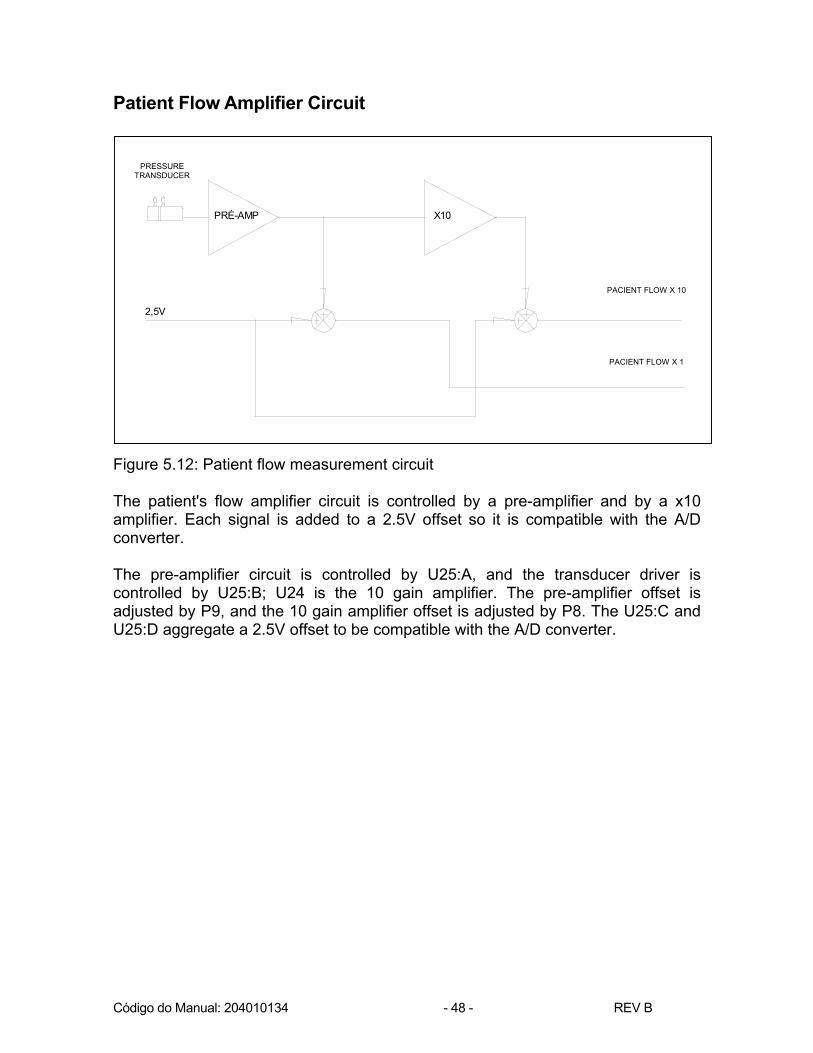
Patient Flow Amplifier Circuit Figure 5.12: Patient flow measurement circuit The patient's flow amplifier circuit is controlled by a pre-amplifier and by a x10 amplifier. Each signal is added to a 2.5V offset so it is compatible with the A/D converter. The pre-amplifier circuit is controlled by U25:A, and the transducer driver is controlled by U25:B; U24 is the 10 gain amplifier. The pre-amplifier offset is adjusted by P9, and the 10 gain amplifier offset is adjusted by P8. The U25:C and U25:D aggregate a 2.5V offset to be compatible with the A/D converter.
PRÉ-AMP X10
Transdutordiferencialde pressão
Fluxo PAC x10
Fluxo PAC x1
2,5V
PRESSURE
TRANSDUCER
PACIENT FLOW X 10
PACIENT FLOW X 1
Código do Manual: 204010134 - 49 - REV B
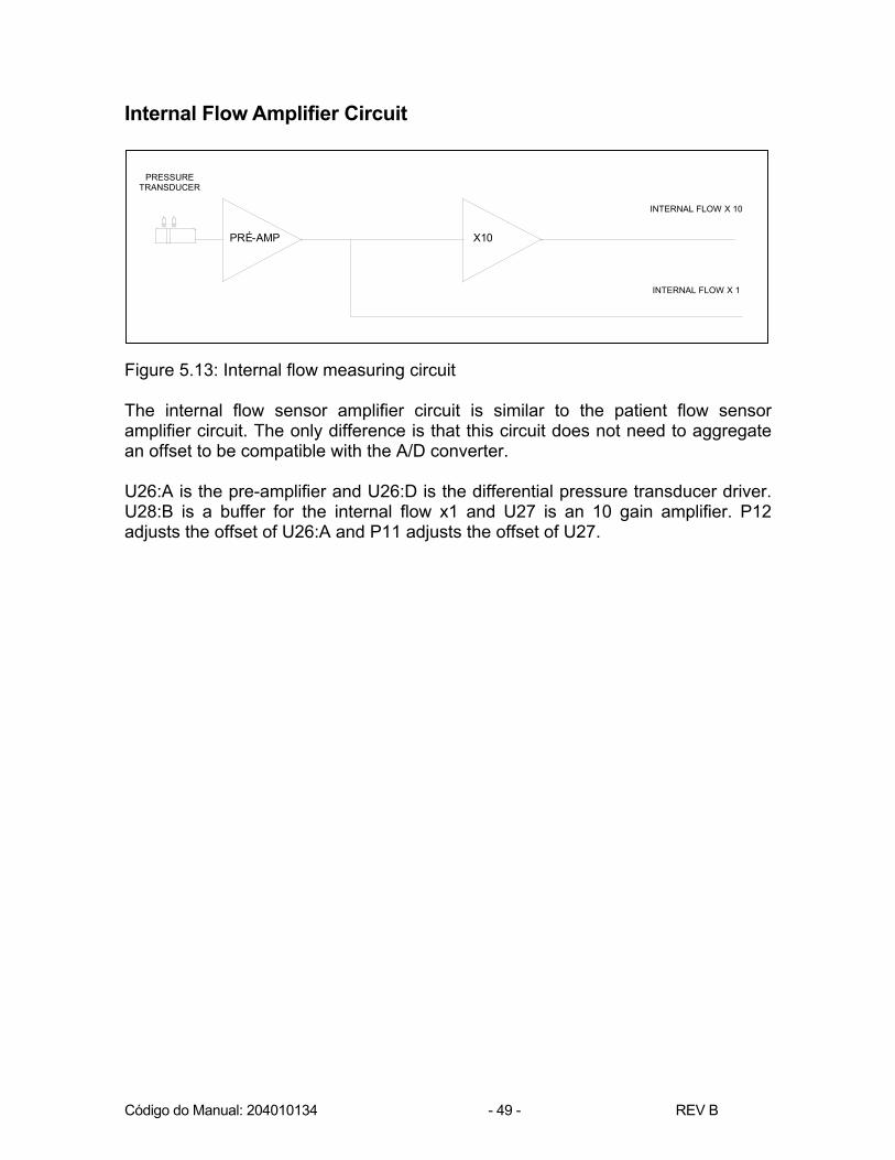
Internal Flow Amplifier Circuit Figure 5.13: Internal flow measuring circuit The internal flow sensor amplifier circuit is similar to the patient flow sensor amplifier circuit. The only difference is that this circuit does not need to aggregate an offset to be compatible with the A/D converter. U26:A is the pre-amplifier and U26:D is the differential pressure transducer driver. U28:B is a buffer for the internal flow x1 and U27 is an 10 gain amplifier. P12 adjusts the offset of U26:A and P11 adjusts the offset of U27.
PRÉ-AMP X10
Transdutordiferencialde pressão
Fluxo INT x10
Fluxo INT x1
PRESSURE
TRANSDUCER
INTERNAL FLOW X 10
INTERNAL FLOW X 1

Código do Manual: 204010134 - 50 - REV B
Figure 5.14: Amplifier Circuit electrical schematic

Código do Manual: 204010134 - 51 - REV B
Pressure sensor amplifier circuit Figure 5.15: Endotracheal pressure measuring circuit The pressure sensor amplifier circuit is carried out by amplifier U28:A. Figure 5.16: Transducer electrical schematic
PRÉ-AMP
Transdutordiferencialde pressão
Pressão paraconversor A/D
2,5V
Pressão parasistema de
controleeletrônico
PRESSURE TRANSDUCER
PRESSURE FOR ELETRONIC CONTROL
SYSTEM
PRESSURE FOR A/D CONVERTER
PATIENT
EXTERNAL FLOW
ENDOTRACHEAL PRESSURE
OVER PRESSURE VALVE
NEBULIZER / TGI
OVER PRESSURE VALVE

Código do Manual: 204010134 - 52 - REV B
6 CABLE AND BOARD CONNECTION SCHEMATIC
Figure 6.1: Cable and board connection schematic
Código do Manual: 204010134 - 53 - REV B
7 CHECKING THE BASE 1 - Objective Establish the Monterey Smart Ventilator central case operation checking procedure. 2 - Required accessories, equipment and tools: − Test gigameter; − 0-100 PSI precision pressure gauge; − 0- to 300-ml standard rotameter; − 0- to 8000-ml standard rotameter; − Air Extension; − O2 Extension; − Distribution network extension; − Adult breathing circuit (tracheas, flow sensor and Y-shaped connector); − Pulmonary test; − Resistance of 20.
3 - Procedure 3.1 Connect the air and O2 extensions to the pneumatic base; 3.1.1 Connect the pressure gauge to the adjusted O2 pressure measuring tap (45
PSI); 3.1.2 Adjust the O2 pressure regulating valve with a 3-mm Allen key until a
pressure of 45 PSI is indicated in the pressure gauge; 3.1.3 Connect the pressure gauge to the adjusted O2 pressure measuring tap (35
PSI); 3.1.4 Adjust the O2 pressure regulating valve with a 3-mm Allen key until a
pressure of 35 PSI is indicated in the pressure gauge; 3.2. Adjust the air pressure-regulating valve 3.2.1 Connect the pressure gauge to the adjusted Air pressure measuring tap (45
PSI); 3.2.2 Adjust the Air pressure regulating valve with a 3-mm Allen key until a
pressure of 45 PSI is indicated in the pressure gauge; 3.2.3 Connect the pressure gauge to the adjusted Air pressure measuring tap (35
PSI); 3.2.4 Adjust the Air pressure regulating valve with a 3-mm Allen key until a
pressure of 35 PSI is indicated in the pressure gauge;
Código do Manual: 204010134 - 54 - REV B
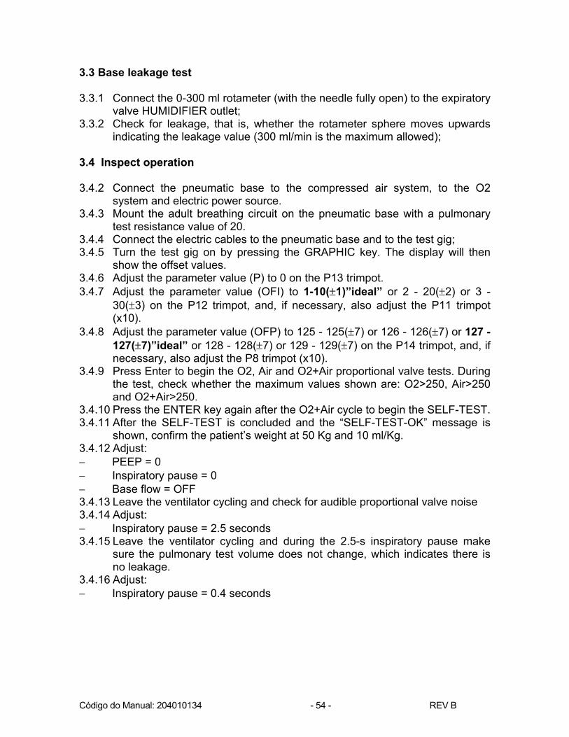
3.3 Base leakage test 3.3.1 Connect the 0-300 ml rotameter (with the needle fully open) to the expiratory
valve HUMIDIFIER outlet; 3.3.2 Check for leakage, that is, whether the rotameter sphere moves upwards
indicating the leakage value (300 ml/min is the maximum allowed); 3.4 Inspect operation 3.4.2 Connect the pneumatic base to the compressed air system, to the O2
system and electric power source. 3.4.3 Mount the adult breathing circuit on the pneumatic base with a pulmonary
test resistance value of 20. 3.4.4 Connect the electric cables to the pneumatic base and to the test gig; 3.4.5 Turn the test gig on by pressing the GRAPHIC key. The display will then
show the offset values. 3.4.6 Adjust the parameter value (P) to 0 on the P13 trimpot. 3.4.7 Adjust the parameter value (OFI) to 1-10(±1)”ideal” or 2 - 20(±2) or 3 -
30(±3) on the P12 trimpot, and, if necessary, also adjust the P11 trimpot (x10).
3.4.8 Adjust the parameter value (OFP) to 125 - 125(±7) or 126 - 126(±7) or 127 - 127(±7)”ideal” or 128 - 128(±7) or 129 - 129(±7) on the P14 trimpot, and, if necessary, also adjust the P8 trimpot (x10).
3.4.9 Press Enter to begin the O2, Air and O2+Air proportional valve tests. During the test, check whether the maximum values shown are: O2>250, Air>250 and O2+Air>250.
3.4.10 Press the ENTER key again after the O2+Air cycle to begin the SELF-TEST. 3.4.11 After the SELF-TEST is concluded and the “SELF-TEST-OK” message is
shown, confirm the patient’s weight at 50 Kg and 10 ml/Kg. 3.4.12 Adjust: − PEEP = 0 − Inspiratory pause = 0 − Base flow = OFF 3.4.13 Leave the ventilator cycling and check for audible proportional valve noise 3.4.14 Adjust: − Inspiratory pause = 2.5 seconds 3.4.15 Leave the ventilator cycling and during the 2.5-s inspiratory pause make
sure the pulmonary test volume does not change, which indicates there is no leakage.
3.4.16 Adjust: − Inspiratory pause = 0.4 seconds

Código do Manual: 204010134 - 55 - REV B
3.5 - Inspect the overpressure valve 3.5.1 Disconnect the expiratory branch from the pneumatic base and obstruct it.
Check whether after approximately two cycles the “OBSTRUCTION IN EXP” message appears and whether when the pressure in the breathing circuit surpasses the adjusted limit-pressure value a system depressurization takes place through the overpressure valve.
3.6 - Inspect Flows. 3.6.1 In the ventilator's menu, adjust: − NEBUL / TGI..: OFF 3.6.2 Connect the 0-8l rotameter to the NEBULIZER's outlet (with the needle fully
open). 3.6.3 During the breathing cycles, check for the presence of flow, which indicates
a valve malfunctioning (from 0 to 50 ml/min). 3.6.4 In the ventilator's menu, adjust: − NEBUL / TGI..: NEB 3.6.5 During inspiratory phase, check the flow (from 4.5 to 8 liters). 3.6.6 In the ventilator's menu, adjust: − NEBUL / TGI..: TGI 3.6.7 Check the flow during the end of the expiratory phase (from 4.5 to 8 liters).

Código do Manual: 204010134 - 56 - REV B
8 CHECKING THE POWER SUPPLY
1 - Objective
Establish the checking procedure for Monterey Smart Ventilator’s 445010007 power supply operation.
2 - Required accessories, equipment and tools:
− Test power supply; − Test gig.
3 - Procedure
3.1 - Connect the test power supply and an on/off key to the power supply to be checked;
3.2 - Connect the test power supply to the electrical outlet; 3.3 - Turn the test power supply on; 3.4 - Perform an audible test to check the proper operation of the power supply, that is, to check whether the relay emits its characteristic sound. 3.5 - Connect one end of the multimeter to the TP1 earth and the other end to the CN1 connector pins. Check the voltages according to the following table:
Pins Voltage 1 0 2 +15V ± 10% 3 +12V ±10% 4 +5V ±10% 5 -12V ±10% 6 0
3.6 - Connect one end of the multimeter to the TP1 earth and the other end to the CN6 connector pins. Check the voltages according to the following table:
Pins Voltage 1 0 2 +13.5V ±10%
3.7 - Connect one end of the multimeter to the TP1 earth and the other end to the CN7 connector pins. Check the voltages according to the following table:
Pins Voltage 1 0 2 +13.5V ±10%
3.8 - Turn the test power supply off. 3.9 - Connect the test gig to the multimeter and to the CN6 and turn the test power supply on; 3.10 - Measure the current in the multimeter (it should be between 230 mA and 260 mA). 3.11 - Turn the test power supply off.

Código do Manual: 204010134 - 57 - REV B
9 ELECTRONIC ADJUSTMENT 1 - Main trimpots: Patient: P9 – Patient transducer offset (x1). P7 – Patient transducer flow gain. P9 – Patient transducer offset (x10). Internal: P12 – Internal transducer offset (x1). P10 – Internal transducer flow gain. P11 – Internal transducer offset (x10). Pressure: P13 – Pressure offset. P1 – PCV curve adjustment. P2 – Peep adjustment. P3 – Pressure filter. P5 – Adjusts the pressure overshoot. Others: P4 – Air blender adjustment. P6 – O2 blender adjustment. P14 – Adjust the inspiratory flow when the sensor is placed in the expiratory valve.

Código do Manual: 204010134 - 58 - REV B
FIGURE
Figure 9.1: General view of the Monterey Smart control board and of its main trimpots.
P11
P4
P9
P1
P14
P6
P3
P8
P12 P7
P2
P10 P13

Código do Manual: 204010134 - 59 - REV B
2 - Objective Establish Monterey Smart Ventilator’s electronic adjustment procedure.
3 - Accessories, equipment and tools − Air Extension; − O2 Extension; − Distribution network extension; − 2000-ml test bag; − 500-ml test bag; − 50-ml test bag; − Resistance of 20; − Resistance of 50; − Adult breathing circuit (tracheas, flow sensor and Y-shaped connector); − Neonatal breathing circuit (tracheas, flow sensor and Y-shaped connector); − Pulmonary test 640; − Oximeter; − Antistatic wristband; 4 - Procedure − To perform this procedure, the ventilator should be open, i.e., the front panel
must be detached, to allow access to the electronic components that need adjusting.
5 - Offset adjustment 5.1 Connect the ventilator to the compressed air system, to the O2 system and
the distribution network. 5.2 Mount the adult breathing circuit with a resistance of 20 in the 2000-ml
bag. 5.3 Turn the ventilator on pressing the GRAPHIC key. The display will then
show the offset values. 5.4 Adjust the parameter value (P) to 0 on the P13 trimpot. 5.5 Adjust the parameter value (OFI) to 1-10(±1)”ideal” or 2 - 20(±2) or 3 -
30(±3) on the P12 trimpot, and, if necessary, also adjust the P11 trimpot (x10).
5.6 Adjust the parameter value (OFP) to 125 - 125(±7) or 126 - 126(±7) or 127 - 127(±7)”ideal” or 128 - 128(±7) or 129 - 129(±7) on the P14 trimpot, and, if necessary, also adjust the P8 trimpot (x10).
5.7 Press Enter to begin the O2, Air and O2+Air proportional valve tests. Wait for the test to be concluded.
5.8 Press the ENTER key again after a O2+Air cycle to begin the SELF-TEST.

Código do Manual: 204010134 - 60 - REV B
5.9 After the SELF-TEST is concluded and the “SELF-TEST-OK” message is shown, confirm the patient’s weight at 50 Kg and 10 ml/Kg.
5.10 Switch the ventilator to the PCV mode and confirm all parameters shown for this mode.
6 - PEEP Adjustment 6.1 Adjustment: − Oxygen concentration = 60% − PEEP CPAP = 0 cmH2O − Limit Pressure = 40 cmH2O − Rate = 14 rpm 6.2 Put the ventilator in the Pxt graphical presentation. 6.3 Press the Oxygen Conc. and Pressure Limit keys simultaneously for the
offset values to be shown. 6.4 Press the STAND BY key. The STAND BY Led is activated, the ventilator
stops cycling and STAND BY appears on the display. 6.5 Reset the PEEP line by adjusting the P13 trimpot. 6.6 Press the STAND BY key. The STAND BY Led goes off, the ventilator
stops cycling and STAND BY disappears from the display. 6.7 Adjust the pressure descent curve inclination with the P1 trimpot. The curve
descent must be as steep as possible, nearly vertical. 6.8 Adjust: − PEEP CPAP = 5 cmH2O 6.9 Check whether the value that is shown is in agreement with the adjusted
one. If not, adjust the PEEP value in trimpot P2. 6.10 Adjust: − PEEP CPAP = 10 cmH2O 6.11 Check whether the value that is shown is in agreement with the adjusted
one. If not, adjust the PEEP value in trimpot P2. 6.12 Adjust: − PEEP CPAP = 15 cmH2O 6.13 Check whether the value that is shown is in agreement with the adjusted
one. If not, adjust the PEEP value in trimpot P2. 6.14 Adjust: − PEEP CPAP = 20 cmH2O 6.15 Check whether the value that is shown is in agreement with the adjusted
one. If not, adjust the PEEP value in trimpot P2. 6.16 If there is vibration at the plateau, adjust P3. 6.17 If during inhalation there is an overshoot (pressure peaks), adjust P5. 6.18 Adjust the resistance to 50. 6.19 Adjust: − PEEP CPAP = 20 cmH2O 6.20 Check whether the value that is shown is in agreement with the adjusted
one. If not, adjust the PEEP value in trimpot P2. 6.21 Adjust:

Código do Manual: 204010134 - 61 - REV B
− PEEP CPAP = 10 cmH2O 6.22 Check whether the value that is shown is in agreement with the adjusted
one. If not, adjust the PEEP value in trimpot P2. Adjust: − PEEP CPAP = 0 cmH2O 6.24 Check whether the value that is shown is in agreement with the adjusted
one. If not, adjust the PEEP value in trimpot P2. 6.25 Switch the ventilator off. 7 - Operating in Neonatal 7.1 Mount the neonatal breathing circuit with a resistance of 50 in the 50-ml
bag. 7.2 Switch the ventilator on and choose a weight of 0,8 Kg and 10 ml/kg. 7.3 Check whether the values shown for Pmax and PEEP are in agreement
with the adjusted ones. If not, adjust the PEEP value on the P2 trimpot, the Pmax vibration on the P3 trimpot, and the overshoot on P5.
7.4 Switch the ventilator off. 8 - Volume Adjustment 8.1 Mount the adult breathing circuit with a pulmonary test resistance value of
20. 8.2 Switch the ventilator on and choose a weight of 50 Kg and 10 ml/kg. 8.3 Adjust: − PEEP CPAP = 0 cmH2O − Oxygen concentration = 60% − Inspiratory Pause = 0 s − In the Base Flow menu = OFF 8.4 Make the FLX and the FLXi values equal on the ventilator menu using
trimpot P10. 8.5 Check, in the pulmonary test, the volume that is shown and, if necessary,
adjust the values using P7. 8.6 Adjust: − Volume = 1,000 ml − Rate = 10 rpm 8.7 Check whether the value that is shown is in agreement with the adjusted
one. If this is not the case, repeat items 8.4 and 8.5 8.8 Adjust: − Volume = 300 ml − Rate = 16 rpm 8.9 Check whether the value that is shown is in agreement with the adjusted
one. If this is not the case, repeat items 8.4 and 8.5
Código do Manual: 204010134 - 62 - REV B
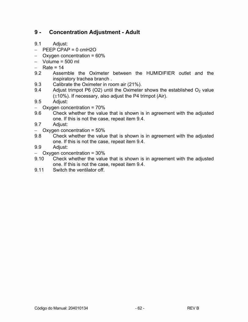
9 - Concentration Adjustment - Adult
9.1 Adjust: − PEEP CPAP = 0 cmH2O − Oxygen concentration = 60% − Volume = 500 ml − Rate = 14 9.2 Assemble the Oximeter between the HUMIDIFIER outlet and the
inspiratory trachea branch . 9.3 Calibrate the Oximeter in room air (21%). 9.4 Adjust trimpot P6 (O2) until the Oximeter shows the established O2 value
(±10%). If necessary, also adjust the P4 trimpot (Air). 9.5 Adjust: − Oxygen concentration = 70% 9.6 Check whether the value that is shown is in agreement with the adjusted
one. If this is not the case, repeat item 9.4. 9.7 Adjust: − Oxygen concentration = 50% 9.8 Check whether the value that is shown is in agreement with the adjusted
one. If this is not the case, repeat item 9.4. 9.9 Adjust: − Oxygen concentration = 30% 9.10 Check whether the value that is shown is in agreement with the adjusted
one. If this is not the case, repeat item 9.4. 9.11 Switch the ventilator off.
Código do Manual: 204010134 - 63 - REV B
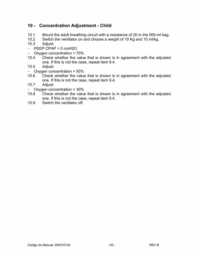
10 - Concentration Adjustment - Child 10.1 Mount the adult breathing circuit with a resistance of 20 in the 500-ml bag. 10.2 Switch the ventilator on and choose a weight of 10 Kg and 10 ml/kg. 10.3 Adjust: − PEEP CPAP = 0 cmH2O − Oxygen concentration = 70% 10.4 Check whether the value that is shown is in agreement with the adjusted
one. If this is not the case, repeat item 9.4. 10.5 Adjust: − Oxygen concentration = 50% 10.6 Check whether the value that is shown is in agreement with the adjusted
one. If this is not the case, repeat item 9.4. 10.7 Adjust: − Oxygen concentration = 30% 10.8 Check whether the value that is shown is in agreement with the adjusted
one. If this is not the case, repeat item 9.4. 10.9 Switch the ventilator off.

Código do Manual: 204010134 - 64 - REV B
10 VERIFYING OPERATION 1. Objective Set up the verification procedure for the Monterey Smart Ventilator’s operation. 2. Accessories, equipment and tools − 0 -100 PSI, TIRE GAUGE precision manometer; − Air Extension; − O2 Extension; − Distribution network extension; − 2000-ml test bag; − 500 ml and 50 ml test bag; − 20 and 50 resistance; − 0-300 ml Standard rotameter; − 0-8l Standard rotameter; − Adult breathing circuit (tracheas, flow sensor and Y-shaped connector); − Child breathing circuit (tracheas, flow sensor and Y-shaped connector); − Pulmonary test 640. 3. Procedure − Assemble the O2, compressed air, and distribution network connections into the
ventilator together with the adult breathing circuit and the 2000 ml test bag with a resistance of 20.
− Switch on the ventilator and choose a weight of 50 Kg and 10 ml/kg. Leave the
equipment operating (cycling) for 72 hours (3 days and 3 nights) so all electric components reach working temperature at the time of the following checks.
− The form field number to be filled in will be the same number as the service
instruction.
Código do Manual: 204010134 - 65 - REV B
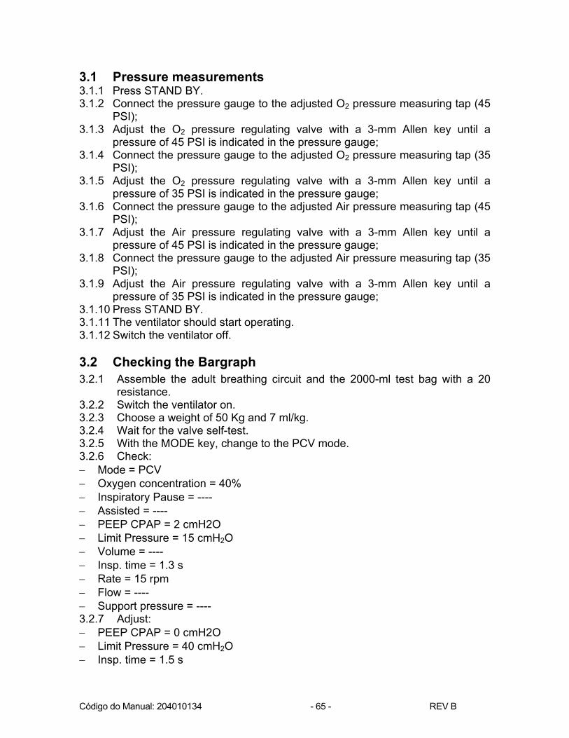
3.1 Pressure measurements 3.1.1 Press STAND BY. 3.1.2 Connect the pressure gauge to the adjusted O2 pressure measuring tap (45
PSI); 3.1.3 Adjust the O2 pressure regulating valve with a 3-mm Allen key until a
pressure of 45 PSI is indicated in the pressure gauge; 3.1.4 Connect the pressure gauge to the adjusted O2 pressure measuring tap (35
PSI); 3.1.5 Adjust the O2 pressure regulating valve with a 3-mm Allen key until a
pressure of 35 PSI is indicated in the pressure gauge; 3.1.6 Connect the pressure gauge to the adjusted Air pressure measuring tap (45
PSI); 3.1.7 Adjust the Air pressure regulating valve with a 3-mm Allen key until a
pressure of 45 PSI is indicated in the pressure gauge; 3.1.8 Connect the pressure gauge to the adjusted Air pressure measuring tap (35
PSI); 3.1.9 Adjust the Air pressure regulating valve with a 3-mm Allen key until a
pressure of 35 PSI is indicated in the pressure gauge; 3.1.10 Press STAND BY. 3.1.11 The ventilator should start operating. 3.1.12 Switch the ventilator off. 3.2 Checking the Bargraph
3.2.1 Assemble the adult breathing circuit and the 2000-ml test bag with a 20 resistance.
3.2.2 Switch the ventilator on. 3.2.3 Choose a weight of 50 Kg and 7 ml/kg. 3.2.4 Wait for the valve self-test. 3.2.5 With the MODE key, change to the PCV mode. 3.2.6 Check: − Mode = PCV − Oxygen concentration = 40% − Inspiratory Pause = ---- − Assisted = ---- − PEEP CPAP = 2 cmH2O − Limit Pressure = 15 cmH2O − Volume = ---- − Insp. time = 1.3 s − Rate = 15 rpm − Flow = ---- − Support pressure = ---- 3.2.7 Adjust: − PEEP CPAP = 0 cmH2O − Limit Pressure = 40 cmH2O − Insp. time = 1.5 s

Código do Manual: 204010134 - 66 - REV B
3.2.8 Check the BARGRAPH, i.e., the leds should stay on until they reach 40 cmH2O and only this last should stay on when the pressure falls.
3.2.9 Adjust: − Limit Pressure = 15 cmH2O − Insp. time = 1.3 s 3.3 Checking the Offset Check the Offset every day (24 hours) 3.3.1 Press the Tidal Volume and PEEP CPAP keys simultaneously. 3.3.2 Press STAND BY. The STAND BY Led is activated, the ventilator stops
cycling and STAND BY appears in the display. 3.3.3 Read the Offset: − P=0 − Ofi=1 - 10(±1) − Ofp=127 - 127(±7) 3.3.4 Check the baseline in the Fxt graph. It must be set to zero. Otherwise,
press the ENTER and the increase keys simultaneously for the baseline to increase or press the ENTER and reduce keys simultaneously for the baseline to decrease.
3.3.5 Press the Tidal Volume and PEEP CPAP keys simultaneously. To make the Offset values disappear.
3.3.6 Press STAND BY for the ventilator to start operating. 3.3.7 Switch the ventilator off. 3.4 Inspect alarms 3.4.1 Disconnect the ventilator from the electric power source network, the
compressed air system and the O2 system. 3.4.2 Switch the ventilator on. 3.4.3 Wait for the valve self-test. 3.4.4 Check that the ventilator shows the following alarms:
CHECK O2 SYSTEM CHECK AIR SYSTEM SELF-TEST: FAILURE
The ventilator should remain deactivated without any type of audible alarm. 3.4.5 Switch the ventilator off. 3.4.6 Do not connect the ventilator to the electric power source. 3.4.7 Connect the ventilator to the compressed air system and the O2 system. 3.4.8 Switch the ventilator on. 3.4.9 Wait for the valve self-test. 3.4.10 Choose a weight of 50 Kg and 7 ml/kg. 3.4.11 The A/C Led must be off and the ventilator must start operating. 3.4.12 Check whether after approximately 2 minutes the ventilator shows the
following alarm in the display: NO ELECTRIC POWER

Código do Manual: 204010134 - 67 - REV B
3.4.13 The audible alarm should be muted and a bell icon with a diagonal trace in it will appear in the display.
3.4.14 Connect the ventilator to the 110 V electric power source. 3.4.15 The A/C Led should be on. 3.4.16 The ventilator should not issue any alarm signal. 3.4.17 Adjust the Oxygen concentration to 21%. 3.4.18 Disconnect the ventilator from the compressed air system. 3.4.19 Check that there ventilator shows the following alarm:
DISCONNECTION 3.4.20 Connect the ventilator to the compressed air system. 3.4.21 Adjust the concentration to 60%. 3.4.22 Disconnect the ventilator from the O2 system. 3.4.23 Check that there ventilator shows the following alarm:
CHECK O2 SYSTEM 3.4.24 Connect the ventilator to the O2 system. The ventilator should mute the
alarm. 3.5 Inspect VCV mode - adult 3.5.1 Leave the equipment operating for at least 1 hour so all electronic
components reach working temperature. 3.5.2 Check: − Mode = VCV − Oxygen concentration = 60% − Inspiratory Pause = 0.4 s − Assisted = ---- − PEEP CPAP = 2 cmH2O − Limit Pressure = 30 cmH2O − Volume = 350 ml − Insp. time = ---- − Rate = 15 rpm − Flow = 46 l/min − Support pressure = ---- 3.5.3 Reset the flow baseline on the monitor (graph F x t). 3.5.4 Remove the bag and the resistance. 3.5.5 Adjust: − Oxygen concentration = 21% − Volume = 2,000 ml − PEEP CPAP = 0 − Flow = 100 l/min − Inspiratory Pause = 0 − In the Flow Type menu = Squared − In the Base Flow menu = 0 3.5.6 Check the ventilator menu for the FLX Flow and the Air FLXi. 3.5.7 Adjust:

Código do Manual: 204010134 - 68 - REV B
− Oxygen concentration = 100% 3.5.8 Check the ventilator menu for the FLX Flow and the O2 FLXi. 3.5.9 Adjust: − Oxygen concentration = 60% − Flow = 110 l/min 3.5.10 Check the ventilator menu for the FLX Flow and gas FLXi. 3.5.11 Adjust: − Volume = 500 ml − Limit Pressure = 35 cmH2O − Rate = 12 rpm − Flow = 25 l/min 3.5.12 Connect the pulmonary test with a 20 resistance. 3.5.13 Check the monitor's Fxt graph for the squared flow (constant) and the
maximum flow. 3.5.14 Check the volume shown on the monitor and in the pulmonary test. 3.5.15 Adjust: − Inspiratory pause = 2.5 seconds 3.5.16 Check the monitor's Fxt graph for the base flow at the end of inhalation
with zero flow and the INVERTED RATIO message due to a I:E ratio greater than 2.5:1.
3.5.17 Check that during the inspiratory pause the pulmonary test volume does not change.
3.5.18 Adjust: − Inspiratory pause = 0.0 − PEEP CPAP = 8 cmH2O − In the base flow menu = 4 lpm 3.5.19 Connect the 2-liter bag. 3.5.20 Check the PEEP in the monitor's P x t graph. 3.6 Inspect the PCV mode 3.6.1 With the MODE key, change to the PCV mode. 3.6.2 Check: − Mode = PCV − Oxygen concentration = 60% − Inspiratory Pause = ---- − Assisted = ---- − PEEP CPAP = 8 cmH2O − Limit Pressure = 15 cmH2O − Volume = ---- − Insp. time = 1.3 s − Rate = 15 − Flow = ---- − Support pressure = ---- 3.6.3 Reset the flow baseline in the monitor (graph F x t).

Código do Manual: 204010134 - 69 - REV B
3.6.4 Check the monitor’s P x t graph for the ADU patient information and the P Max and the PEEP values in the graph .
3.6.5 Adjust: − Limit Pressure = 30 cmH2O − PEEP CPAP = 15 cmH2O 3.6.6 Check, in the monitor P x t graph the values of P Max and PEEP in the
graph. 3.6.7 Disconnect the expiratory branch from the pneumatic base and obstruct it.
Check whether after approximately two cycles the “OBSTRUCTION IN EXP” message appears and whether when the pressure in the breathing circuit surpasses the adjusted limit-pressure value a system depressurization takes place through the overpressure valve.
3.7 Inspect the PCV/AV mode 3.7.1 With the MODE key, change to the PCV/AV mode. 3.7.2 Check: − Mode = PCV/AV − Oxygen concentration = 60% − Inspiratory Pause = ---- − Assisted = ---- − PEEP CPAP = 15 cmH2O − Limit Pressure = 25 cmH2O − Volume = 350 ml − Insp. time = 1.3 s − Rate = 15 − Flow = ---- − Support pressure = ---- 3.7.3 Reset the flow baseline in the monitor (graph F x t). 3.7.4 Adjust: − Volume = 500 ml − Limit Pressure = 30 cmH2O − PEEP CPAP = 5 cmH2O 3.7.5 After the 500 ml volume is reached, check the monitor for the maximum
pressure value.

Código do Manual: 204010134 - 70 - REV B
3.8 Inspect the SIMV/V mode 3.8.1 Using the MODE key, go to the SIMV/V mode. 3.8.2 Check: − Mode = SIMV/V − Oxygen concentration = 60% − Inspiratory Pause = 0.4 − Assisted = 2 cmH2O − PEEP CPAP = 5 cmH2O − Limit Pressure = 30 cmH2O − Volume = 350 − Insp. time = ---- − Rate = 9 rpm − Flow = 46 l/min − Support pressure = ---- 3.8.3 Reset the flow baseline in the monitor (graph F x t). 3.8.4 During the mandatory cycles, check the volume and the PEEP value at
the end of the exhalation. 3.8.5 When stimulating the bag during the WINDOW interval, check that the
cycle is triggered. Also check that the following message appears ASSISTED: PRESSURE TRIGGER, and whether the breathing rate increases in the monitor.
3.8.6 Adjust: − Assisted = ---- − In the trigger flow menu = 4 lpm 3.8.7 When stimulating the bag during the WINDOW interval, check that the
cycle is triggered. Also check that the following message appears ASSISTED: FLOW TRIGGER , and whether the breathing rate increases in the monitor.
3.8.8 Adjust: − Assisted = 2 cmH2O − In the trigger flow menu = OFF 3.9 Inspect the SIMV/P mode 3.9.1 Using the MODE key, go to the SIMV/P mode. 3.9.2 Check: − Mode = SIMV/P − Oxygen concentration = 60% − Inspiratory Pause = ---- − Assisted = 2 cmH2O − PEEP CPAP = 5 cmH2O − Limit Pressure = 15 cmH2O − Volume = ---- − Insp. time = 1.3 s
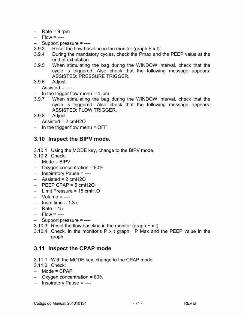
Código do Manual: 204010134 - 71 - REV B
− Rate = 9 rpm − Flow = ---- − Support pressure = ---- 3.9.3 Reset the flow baseline in the monitor (graph F x t). 3.9.4 During the mandatory cycles, check the Pmax and the PEEP value at the
end of exhalation. 3.9.5 When stimulating the bag during the WINDOW interval, check that the
cycle is triggered. Also check that the following message appears: ASSISTED: PRESSURE TRIGGER.
3.9.6 Adjust: − Assisted = ---- − In the trigger flow menu = 4 lpm 3.9.7 When stimulating the bag during the WINDOW interval, check that the
cycle is triggered. Also check that the following message appears: ASSISTED: FLOW TRIGGER.
3.9.8 Adjust: − Assisted = 2 cmH2O − In the trigger flow menu = OFF 3.10 Inspect the BIPV mode. 3.10.1 Using the MODE key, change to the BIPV mode. 3.10.2 Check: − Mode = BIPV − Oxygen concentration = 80% − Inspiratory Pause = ---- − Assisted = 2 cmH2O − PEEP CPAP = 5 cmH2O − Limit Pressure = 15 cmH2O − Volume = ---- − Insp. time = 1.3 s − Rate = 15 − Flow = ---- − Support pressure = ---- 3.10.3 Reset the flow baseline in the monitor (graph F x t). 3.10.4 Check, in the monitor’s P x t graph, P Max and the PEEP value in the
graph. 3.11 Inspect the CPAP mode 3.11.1 With the MODE key, change to the CPAP mode. 3.11.2 Check: − Mode = CPAP − Oxygen concentration = 80% − Inspiratory Pause = ----

Código do Manual: 204010134 - 72 - REV B
− Assisted = 2 cmH2O − PEEP CPAP = 5 cmH2O − Limit Pressure = 15 cmH2O − Volume = ---- − Insp. time = ---- − Rate = ---- − Flow = ---- − Support pressure = ---- 3.11.3 Adjust: − P.Support = 10 cmH20 3.11.4 Reset the flow baseline in the monitor (graph F x t). 3.11.5 When stimulating the bag, check in the monitor's P x t graph that a cycle is
started and that this cycle has a supported pressure of 10 cmH2O. If the following message appears: SPONTANEOUS: PRESSURE TRIGGER.
3.11.6 Leave the ventilator operating without stimulating the bag and check that the APNEA message appears.
3.12 Inspect PSV Mode 3.12.1 Using the MODE key, change to the CPAP mode. 3.12.2 Check: − Mode = PSV − Oxygen concentration = 80% − Inspiratory Pause = ---- − Assisted = 2 cmH2O − PEEP CPAP = 5 cmH2O − Limit Pressure = 15 cmH2O − Volume = ---- − Insp. time = 1.3 s − Rate = 15 − Flow = ---- − Support Pressure = 10 cmH2O 3.12.3 Reset the flow baseline in the monitor (graph F x t). 3.12.4 When stimulating the bag, check in the monitor's P x t graph that a cycle is
started and that this cycle has a supported pressure of 10 cmH2O. Also check that the following message appears: SPONTANEOUS: PRESSURE TRIGGER.
3.12.5 Leave the ventilator operating without stimulating the bag and check that the PVC CONTROLLED message appears.
3.12.6 Switch the Ventilator off. 3.13 Inspect the PCV - Infant mode 3.13.1 Assemble the child breathing circuit and the 500-ml bag with a 50
resistance.

Código do Manual: 204010134 - 73 - REV B
3.13.2 Switch the ventilator on. 3.13.3 Wait for the valve self-test. 3.13.4 Choose a weight of 6.5 Kg and 8 ml/kg. 3.13.5 Check: − Mode = PCV − Oxygen concentration = 40% − Inspiratory Pause = ---- − Assisted = ---- − PEEP CPAP = 5 cmH2O − Limit Pressure = 15 cmH2O − Volume = ---- − Insp. time = 0.73 s − Rate = 28 − Flow = ---- − Support pressure = ---- 3.13.6 Reset the flow baseline in the monitor (graph F x t). 3.13.7 Check the monitor’s P x t graph for the INF patient information and the P
Max and the PEEP values in the graph. 3.13.8 Disconnect the expiratory branch from the pneumatic base and obstruct it.
Check whether after approximately two cycles the “OBSTRUCTION IN EXP” message appears and whether when the pressure in the breathing circuit surpasses the adjusted limit-pressure value a system depressurization takes place through the overpressure valve.
3.14 Inspect the SIMV/P - child mode 3.14.1 Using the MODE key, go to the SIMV/P mode. 3.14.2 Check: − Mode = SIMV/P − Oxygen concentration = 40% − Inspiratory Pause = ---- − Assisted = 2 cmH2O − PEEP CPAP = 5 cmH2O − Limit Pressure = 15 cmH2O − Volume = ---- − Insp. time = 0.73 s − Rate = 17 rpm − Flow = ---- − Support pressure = ---- 3.14.3 Reset the flow baseline in the monitor (graph F x t). 3.14.4 During the mandatory cycles, check the P Max and the PEEP value in the
graph. 3.14.5 When stimulating the bag during the WINDOW interval, check that the
cycle is triggered. Also check that the following message appears
Código do Manual: 204010134 - 74 - REV B
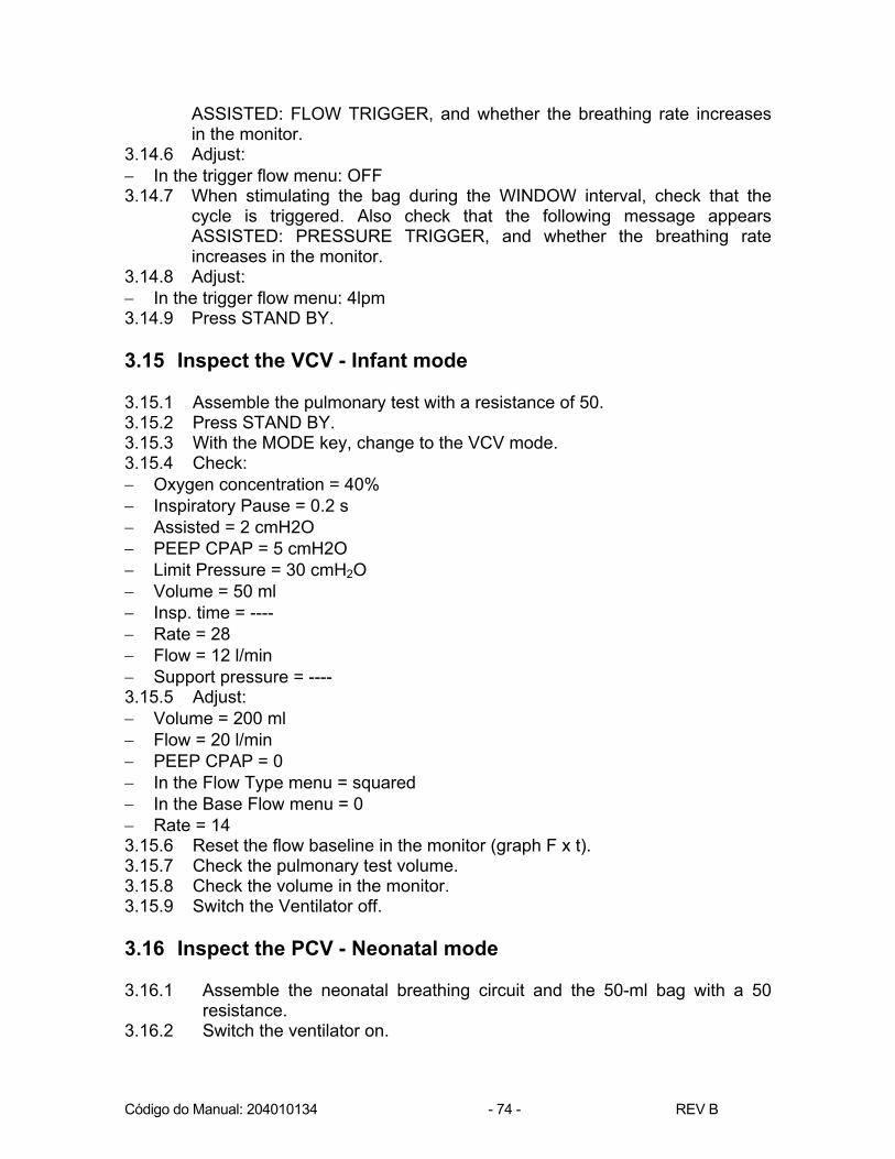
ASSISTED: FLOW TRIGGER, and whether the breathing rate increases in the monitor.
3.14.6 Adjust: − In the trigger flow menu: OFF 3.14.7 When stimulating the bag during the WINDOW interval, check that the
cycle is triggered. Also check that the following message appears ASSISTED: PRESSURE TRIGGER, and whether the breathing rate increases in the monitor.
3.14.8 Adjust: − In the trigger flow menu: 4lpm 3.14.9 Press STAND BY. 3.15 Inspect the VCV - Infant mode 3.15.1 Assemble the pulmonary test with a resistance of 50. 3.15.2 Press STAND BY. 3.15.3 With the MODE key, change to the VCV mode. 3.15.4 Check: − Oxygen concentration = 40% − Inspiratory Pause = 0.2 s − Assisted = 2 cmH2O − PEEP CPAP = 5 cmH2O − Limit Pressure = 30 cmH2O − Volume = 50 ml − Insp. time = ---- − Rate = 28 − Flow = 12 l/min − Support pressure = ---- 3.15.5 Adjust: − Volume = 200 ml − Flow = 20 l/min − PEEP CPAP = 0 − In the Flow Type menu = squared − In the Base Flow menu = 0 − Rate = 14 3.15.6 Reset the flow baseline in the monitor (graph F x t). 3.15.7 Check the pulmonary test volume. 3.15.8 Check the volume in the monitor. 3.15.9 Switch the Ventilator off. 3.16 Inspect the PCV - Neonatal mode 3.16.1 Assemble the neonatal breathing circuit and the 50-ml bag with a 50
resistance. 3.16.2 Switch the ventilator on.
Código do Manual: 204010134 - 75 - REV B
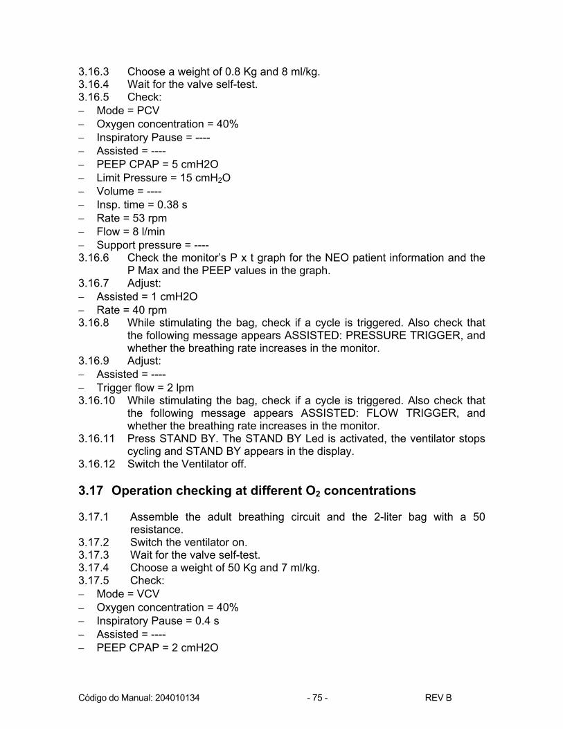
3.16.3 Choose a weight of 0.8 Kg and 8 ml/kg. 3.16.4 Wait for the valve self-test. 3.16.5 Check: − Mode = PCV − Oxygen concentration = 40% − Inspiratory Pause = ---- − Assisted = ---- − PEEP CPAP = 5 cmH2O − Limit Pressure = 15 cmH2O − Volume = ---- − Insp. time = 0.38 s − Rate = 53 rpm − Flow = 8 l/min − Support pressure = ---- 3.16.6 Check the monitor’s P x t graph for the NEO patient information and the
P Max and the PEEP values in the graph. 3.16.7 Adjust: − Assisted = 1 cmH2O − Rate = 40 rpm 3.16.8 While stimulating the bag, check if a cycle is triggered. Also check that
the following message appears ASSISTED: PRESSURE TRIGGER, and whether the breathing rate increases in the monitor.
3.16.9 Adjust: − Assisted = ---- − Trigger flow = 2 lpm 3.16.10 While stimulating the bag, check if a cycle is triggered. Also check that
the following message appears ASSISTED: FLOW TRIGGER, and whether the breathing rate increases in the monitor.
3.16.11 Press STAND BY. The STAND BY Led is activated, the ventilator stops cycling and STAND BY appears in the display.
3.16.12 Switch the Ventilator off. 3.17 Operation checking at different O2 concentrations 3.17.1 Assemble the adult breathing circuit and the 2-liter bag with a 50
resistance. 3.17.2 Switch the ventilator on. 3.17.3 Wait for the valve self-test. 3.17.4 Choose a weight of 50 Kg and 7 ml/kg. 3.17.5 Check: − Mode = VCV − Oxygen concentration = 40% − Inspiratory Pause = 0.4 s − Assisted = ---- − PEEP CPAP = 2 cmH2O

Código do Manual: 204010134 - 76 - REV B
− Limit Pressure = 30 cmH2O − Volume = 350 ml − Insp. time = ---- − Rate = 15 rpm − Flow = 46 l/min − Support pressure = ---- 3.17.6 Adjust: − Flow = 8 l/min − Base Flow = OFF − Oxygen concentration = 21% − PEEP CPAP = 0 3.17.7 Check if the ventilator cycles normally for approximately 1.5 minutes
showing the INVERTED RATIO message. 3.17.8 Press the Oxygen Conc. and manual cycle keys simultaneously. The
ventilator should enter a 100% O2 operation. 3.17.9 Check whether the figure indicating the 100% O2 condition appears and
whether the ventilator cycles normally for 1.5 minutes, afterwards returning to 21%.
3.17.10 Adjust: − Oxygen concentration = 60% 3.17.11 Check that the ventilator cycles regularly for about 1.5 minutes. 3.18 Inspect Manual Cycle 3.18.1 Adjust: − Flow = 46 l/min 3.18.2 In the ventilator's menu, check that at the end of the exhalation the FLXi
value is between -5 and +5. 3.18.3 Press: − Manual Cycle 3.18.4 In the monitor, check that the cycle is immediately started and that the
rate increases. Also check that the following message appears: ASSISTED: MANUAL TRIGGER
3.19 Inspect Monitor 3.19.1 Adjust: − In the monitor's menu, the "high" pressure alarm = 15 cmH2O 3.19.2 Check whether after approximately 15 seconds, the HIGH PRESSURE
alarm is shown on the display.

Código do Manual: 204010134 - 77 - REV B
3.20 Inspect Flows 3.20.1 In the ventilator's menu, adjust: − NEBUL / TGI..: OFF 3.20.2 Connect the 0-8l rotameter to the NEBULIZER's outlet (with the needle
fully open). 3.20.3 During the breathing cycles, check for the presence of flow, which
indicates a valve malfunctioning (from 0 to 50 ml/min). 3.20.4 In the ventilator's menu, adjust: − NEBUL / TGI..: NEB 3.20.5 During inspiratory phase, check the flow (from 4.5 to 8 liters). 3.20.6 In the ventilator's menu, adjust: − NEBUL / TGI..: TGI 3.20.7 During the end of the expiratory phase, check the flow (from 4.5 to 8
liters).
3.21 Inspect Leakages 3.21.1 Press STAND BY. The STAND BY Led is activated, the ventilator stops
cycling and STAND BY appears in the display. 3.21.2 Connect the 0 to 300 ml rotameter to the NEBULIZER's outlet (with the
needle fully open). 3.21.3 Check if there is any leakage (from 0 to 300 ml/min).
3.22 Inspect the ILV (Independent Lung Ventilation) in two Ventilators 3.22.1 Connect the master/slave serial cable to the ventilator serial outlets. The
positioning of this cable will establish which machine will be the master and the slave during the test;
3.22.2 Connect the adult breathing circuit and the 2000-ml test bag with a 20 resistance to both ventilators.
3.22.3 Switch on both ventilators and choose a weight of 50 Kg and 10 ml/kg for both.
3.22.4 Through the MODE key, change the ventilators to the SIMV/V mode. The SLAVE ventilator frequency must be lower than or equal to the MASTER ventilator's.
3.22.5 When stimulating the “SLAVE” ventilator bag during the WINDOW interval, check that only this ventilator’s cycle is triggered. Also check that the following message appears ASSISTED: ILV TRIGGER, and that the breathing rate in the monitor is equal to the ‘MASTER’ ventilator’s.
3.22.6 When stimulating the “MASTER” ventilator bag during the WINDOW interval, check that the cycle is simultaneously triggered in both ventilators.
3.22.7 Press STAND BY on both ventilators. 3.22.8 Invert the master/slave cable position and repeat the procedures
described in 3.22.5 and 3.22.6. 3.22.9 Switch the ventilator off.

Código do Manual: 204010134 - 78 - REV B
11 ELECTRIC AND PNEUMATIC SUPPLY
1. Initially check if the on/off key located at the rear panel of the MONTEREY SMART Ventilator is in the OFF position.
2. Attach the O2 input and compressed air inlet connections located at the
rear panel of the MONTEREY SMART Ventilator to the corresponding power supply for these gases. Use the extensions provided with the Ventilator.
Attention
The oxygen and compressed air supply pressures must be in a range between 45 and 100 psi (310 and 690 kPa). Connect the air filter provided with the equipment between the Ventilator's compressed air connection and its respective extension. The compressed air from the supply must be free of humidity, oil and impurities.
NOTES: The Monterey Smart ventilator is equipped with internal pressure regulating valves, and it may be connected directly to hospital network gas outlets installed according to the norms in force. Therefore, using an external regulating valve is not recommended.
3. Connect the MONTEREY SMART Ventilator to a 110 or 220 VAC power
source using the power cable provided with the equipment.
Figure 11.1. Three-pin Nema 5-15P electrical plug.

Código do Manual: 204010134 - 79 - REV B
NOTE: The Ventilator can be supplied either with 110 or 220 VAC, as it has automatic voltage selection.
4. Supply Heated Humidifier KT-6060 either with 110 or
220 VAC using the electric outlet located at the rear panel of the MONTEREY SMART Ventilator. The Heated Humidifier has an automatic voltage selection.
5. The Ventilator has a rechargeable internal battery that allows the device to
be used temporarily without being connected to an electric power source. In case of a power failure, the Ventilator will be supplied automatically through its internal battery and ventilation will not be discontinued. The power supply indicator will flash and an alarm will sound if there is a POWER FAILURE when the Ventilator is being powered by its internal battery.

Código do Manual: 204010134 - 80 - REV B
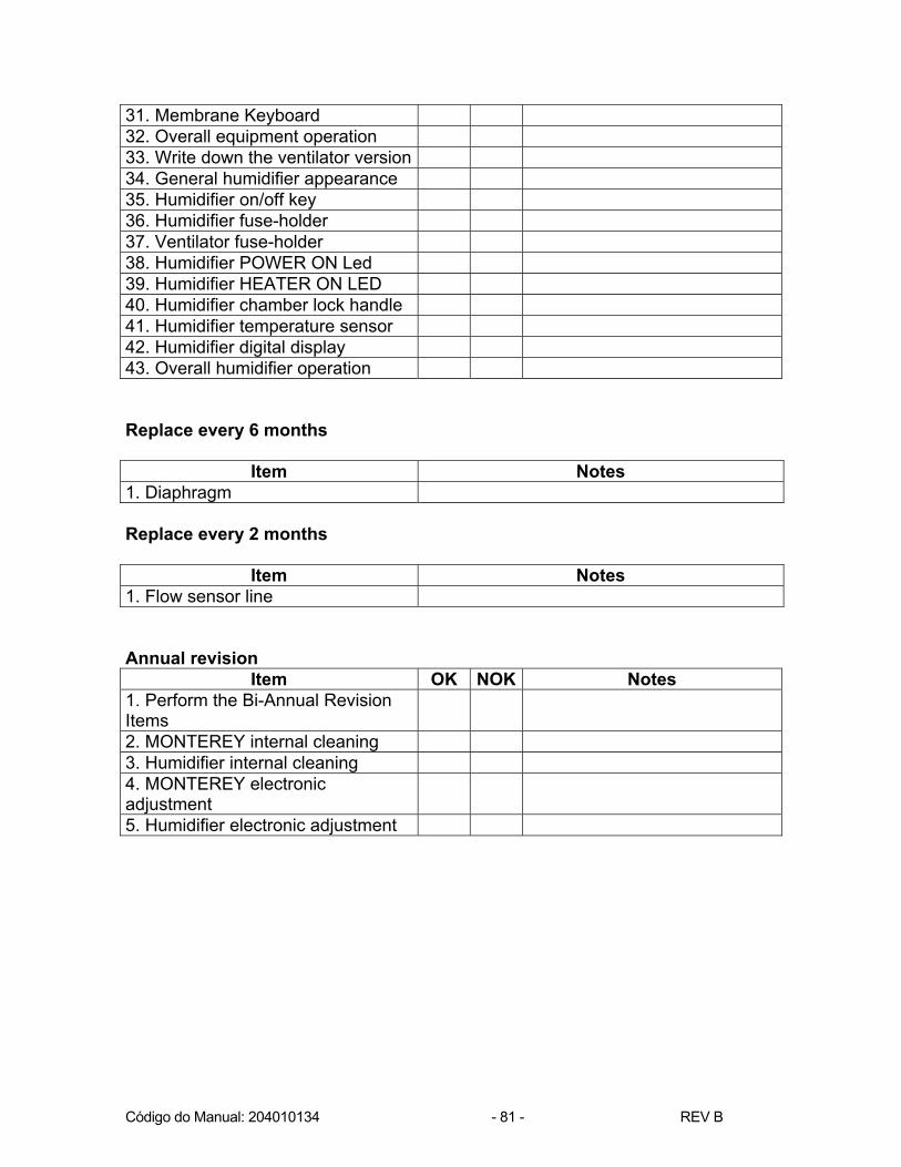
12 REVISION PROGRAM The revisions must be performed every six months and requested by the user. Half-annual Revision
Item OK NOK Notes 1. General appearance - paint 2. Mobile trolley and base 3. Lateral hooks and column 4. Rear hook and column 5. Rear handle and column 6. Humidifier support pins 7. Threaded compressed air inlet and connection leakage
8. Threaded O2 inlet and connection leakage
9. Pressure of the compressed air regulating valve (35 ± 2 psi)
10. Pressure of the O2 regulating valve. ( 35 ± 2 psi)
11. On/off key 12. Electric outlet 13. Humidifier tap 14. Serial port RS-232C 15. 12v external battery outlet 16. Tray's support secure 17. Monitor tray and belt 18. Mobile arm support secure 19. Operation of the contrast controls
20. Operation of the loud speaker 21. Blue flow sensor connection 22. White flow sensor connection 23. Nebulizer connection 24. INS/EXP block fixing system – Thread and Screw
25. Diaphragm 26. Bargraph Led 27. Power supply Led 28. Battery Led 29. Manual cycle key 30. Control display
Código do Manual: 204010134 - 81 - REV B
31. Membrane Keyboard 32. Overall equipment operation 33. Write down the ventilator version 34. General humidifier appearance 35. Humidifier on/off key 36. Humidifier fuse-holder 37. Ventilator fuse-holder 38. Humidifier POWER ON Led 39. Humidifier HEATER ON LED 40. Humidifier chamber lock handle 41. Humidifier temperature sensor 42. Humidifier digital display 43. Overall humidifier operation
Replace every 6 months
Item Notes 1. Diaphragm Replace every 2 months
Item Notes
1. Flow sensor line
Annual revision Item OK NOK Notes
1. Perform the Bi-Annual Revision Items
2. MONTEREY internal cleaning 3. Humidifier internal cleaning 4. MONTEREY electronic adjustment
5. Humidifier electronic adjustment

Código do Manual: 204010134 - 82 - REV B
13 PREVENTIVE MAINTENANCE 1. At least once a month, check that the tubes, sensors, cables, and other Ventilator components are not damaged, worn out or cracked. If there is any damage, replace the component. Do not use damaged components. 2. The expiratory valve diaphragm must be carefully checked at least once a month to ensure its integrity. 3. The expiratory valve diaphragm should be replaced at least once every 6 (six) months and whenever necessary. NOTE:
The expiratory valve block must be tightly fastened to the Ventilator’s front connection panel so there is no gas leakage. Periodically check the sealing ring (O-ring).
4. Periodically check for the perfect condition of the Heated Humidifier's cap rubber mounting so the chamber is tightly sealed when closed. If necessary, replace it with a new mounting. 5. Check the condition and periodically replace the breathing circuit's corrugated tubes, as these are components subject to normal wear and tear. 6. If the maximum inspiratory pressure does not reach the expected value, check, initially: · that there is no leakage in the breathing circuit; · that there is no leakage in the humidifier's cap; · that all connections are tight; · that the pressure control is not adjusted too low; · that the tidal volume control is not adjusted too low; · that O2 and compressed air supply pressures are not too low; · that the expiratory valve set is correctly assembled with a clean and well-preserved diaphragm. . that the inspiratory flow pressure control is not adjusted too low.
Código do Manual: 204010134 - 83 - REV B
7. If the tidal volume does not reach the expected value, check, initially: · that there is no leakage in the breathing circuit; · that there is no leakage in the humidifier's cap; · that all connections are tight; · that the pressure control is not adjusted too low; · that O2 and compressed air supply pressures are not too low; · that the expiratory valve set is correctly assembled with a clean and well-preserved diaphragm. . that the inspiratory flow pressure control is not adjusted too low. that the flow line position at the end of the Fxt graph expiration is not at zero, i.e., with a deviation going up or down. In this case, adjust the graph’s vertical position keeping the ENTER key depressed while you press the increase key (to make the graph go up) or the decrease key (to make the graph go down). 8. If you are unable to supply the MONTEREY SMART Ventilator with electric power, initially check: · if there is electric energy at the 100 to 240 VAC outlet; that the ventilator fuse has not blown; whether the O2 and compressed air system pressures are not too low; 9. The compressed air filter should be opened and cleaned two or three times a year, depending on how much the Ventilator is used and the purity of the compressed air. The condensation from the filter drains automatically. 10. Use only the sensors, cables and tubes specified by TAKAOKA for the MONTEREY SMART Ventilator. 11. Do not use the MONTEREY SMART Ventilator if the self-test detects any abnormality. Solve the problem by calling a TAKAOKA authorized representative. 12. The Ventilator must undergo an annual revision by a TAKAOKA authorized technician to be re-calibrated. Rechargeable internal battery: · Whenever possible, keep the internal battery fully charged to obtain a longer useful life. Constant battery discharges decrease the useful life. · The internal battery is sealed and does not require maintenance. In case there is any operating problem with the battery, call TAKAOKA’S authorized Technical Assistance. · In the event it is not possible to charge the battery normally through the electric power supply, check whether there is power in the electricity outlet.

Código do Manual: 204010134 - 84 - REV B
Attention · Only use original TAKAOKA replacement parts. Using non-original parts could be hazardous for the patient. · Do not perform any internal service in the MONTEREY SMART Ventilator and do not open its cabinet. To perform any internal maintenance on the Ventilator or to make a periodic revision, call TAKAOKA'S authorized Technical Assistance.

Código do Manual: 204010134 - 85 - REV B

Código do Manual: 204010134 - 86 - REV B

Código do Manual: 204010134 - 87 - REV B
TECHNICAL ASSISTANCE
K. TAKAOKA Indústria e Comércio Ltda. advises that only its Technical Assistance Centers are authorized to provide technical assistance for any equipment supplied by the company. Service provided by third parties implies the running of serious risks since the origin of the parts used is unknown and the labor does not conform to the strict quality standards laid down by K. TAKAOKA. We cannot guarantee the correct functioning of the equipment we manufactured when it has been serviced by unauthorized personnel. Any request for technical assistance and/or preventive maintenance, either by contract or not, shall be directed to K. TAKAOKA or one of its exclusively authorized representatives.

Código do Manual: 204010134 - 88 - REV B

Código do Manual: 204010134 - 89 - REV B
Information for Technical Assistance This card shall be filled in and returned with the equipament. Name Hospital Address Fone Number Block Zip Code City State Failure Description : ______________________________________________________________________________________________________________________________________________________________________________________________________
Fábrica: Av. Bosque da Saúde, 515 - CEP 04142-091 - Tel: (011) 5586-1000 - Fax: (011) 5589-7313 Vendas e Show-Room: Rua Bertioga, 385 - CEP 04141-100 - Tel: (011) 5586-1100 - São Paulo / SP
E-mail: [email protected] - Home Page: www.takaoka.com.br Information for Technical Assistance This card shall be filled in and returned with the equipament. Name Hospital Address Fone Number Block Zip Code City State Failure Description : ______________________________________________________________________________________________________________________________________________________________________________________________________
Fábrica: Av. Bosque da Saúde, 515 - CEP 04142-091 - Tel: (011) 5586-1000 - Fax: (011) 5589-7313 Vendas e Show-Room: Rua Bertioga, 385 - CEP 04141-100 - Tel: (011) 5586-1100 - São Paulo / SP
E-mail: [email protected] - Home Page: www.takaoka.com.br