msi mainboard ms-7345 (v1.x) user manual
DESCRIPTION
P35 platinum series motherbordTRANSCRIPT
i
P35 Platinum seriesMS-7345 (v1.X) Mainboard
G52-73451X2
7345v1.0-0 Preface.p65 2007/5/11, 下午 02:021

ii
Copyright Notice
The material in this document is the intellectual property of MICRO-STARINTERNATIONAL. We take every care in the preparation of this document, but noguarantee is given as to the correctness of its contents. Our products are undercontinual improvement and we reserve the right to make changes without notice.
Trademarks
All trademarks are the properties of their respective owners.
NVIDIA, the NVIDIA logo, DualNet, and nForce are registered trademarks or trade-marks of NVIDIA Corporation in the United States and/or other countries.AMD, Athlon™, Athlon™ XP, Thoroughbred™, and Duron™ are registered trade-marks of AMD Corporation.Intel® and Pentium® are registered trademarks of Intel Corporation.PS/2 and OS®/2 are registered trademarks of International Business MachinesCorporation.Windows® 95/98/2000/NT/XP are registered trademarks of Microsoft Corporation.Netware® is a registered trademark of Novell, Inc.Award® is a registered trademark of Phoenix Technologies Ltd.AMI® is a registered trademark of American Megatrends Inc.
Revision History
Revision Revision History DateV1.0 First release for G33 March 2007V1.1 First release for P35 March 2007
Technical Support
If a problem arises with your system and no solution can be obtained from the user’smanual, please contact your place of purchase or local distributor. Alternatively,please try the following help resources for further guidance.
7345v1.0-0 Preface.p65 2007/5/11, 下午 02:022

iii
Safety Instructions
CAUTION: Danger of explos ion if bat tery is incorrectly replaced.Replace only with the same or equivalent type recommended by themanufacturer.
1. Always read the safety instructions carefully.2. Keep this User’s Manual for future reference.3. Keep this equipment away from humidity.4. Lay this equipment on a reliable f lat surface before setting it up.5. The openings on the enclosure are for air convection hence protects the equip-
ment from overheating. DO NOT COVER THE OPENINGS.6. Make sure the voltage of the power source and adjust properly 110/220V be-
fore connecting the equipment to the power inlet.7. Place the power cord such a way that people can not step on it. Do not place
anything over the power cord.8. Always Unplug the Power Cord before inserting any add-on card or module.9. All cautions and warnings on the equipment should be noted.10. Never pour any liquid into the opening that could damage or cause electrical
shock.11. If any of the following situations arises, get the equipment checked by a service
personnel:Ü The power cord or plug is damaged.Ü Liquid has penetrated into the equipment.Ü The equipment has been exposed to moisture.Ü The equipment has not work well or you can not get it work according to
User’s Manual.Ü The equipment has dropped and damaged.Ü The equipment has obvious sign of breakage.
12. DO NOT LEAVE THIS EQUIPMENT IN AN ENVIRONMENT UNCONDITIONED, STOR-AGE TEMPERATURE ABOVE 600 C (1400F), IT MAY DAMAGE THE EQUIPMENT.
7345v1.0-0 Preface.p65 2007/5/11, 下午 02:023

iv
FCC-B Radio Frequency Interference Statement
This equipment has beentested and found to complywith the limits for a Class Bdigital device, pursuant to Part15 of the FCC Rules. These limits are designed to provide reasonable protectionagainst harmful interference in a residential installation. This equipment generates,uses and can radiate radio frequency energy and, if not installed and used in accor-dance with the instructions, may cause harmful interference to radio communications.However, there is no guarantee that interference will not occur in a particularinstallation. If this equipment does cause harmful interference to radio or televisionreception, which can be determined by turning the equipment off and on, the user isencouraged to try to correct the interference by one or more of the measures listedbelow.
Ü Reorient or relocate the receiving antenna.
Ü Increase the separation between the equipment and receiver.
Ü Connect the equipment into an outlet on a circuit different from that towhich the receiver is connected.
Ü Consult the dealer or an experienced radio/television technician for help.
Notice 1The changes or modif ications not expressly approved by the party responsible forcompliance could void the user’s authority to operate the equipment.
Notice 2Shielded interface cables and A.C. power cord, if any, must be used in order tocomply with the emission limits.
VOIR LA NOTICE D’INSTALLATION AVANT DE RACCORDER AU RESEAU.
Micro-Star InternationalMS-7345
This device complies with Part 15 of the FCC Rules. Operation is subject to thefollowing two conditions:(1) this device may not cause harmful interference, and(2) this device must accept any interference received, including interference that
may cause undesired operation.
7345v1.0-0 Preface.p65 2007/5/11, 下午 02:024
v
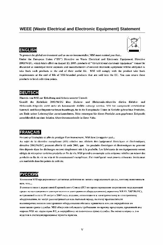
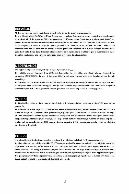
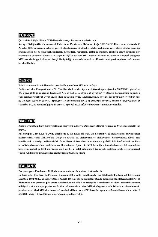
WEEE (Waste Electrical and Electronic Equipment) Statement
7345v1.0-0 Preface.p65 2007/5/11, 下午 02:025
vi
7345v1.0-0 Preface.p65 2007/5/11, 下午 02:026
vii
7345v1.0-0 Preface.p65 2007/5/11, 下午 02:027
viii
CONTENTSCopyright Notice .............................................................................................................. iiTrademarks ....................................................................................................................... iiRevision History .............................................................................................................. iiTechnical Support ........................................................................................................... iiSafety Instructions ......................................................................................................... iiiFCC-B Radio Frequency Interference Statement ........................................................ ivWEEE (Waste Electrical and Electronic Equipment) Statement .................................... vChapter 1. Getting Started .................................................................................... 1-1
Mainboard Specifications ................................................................................... 1-2Mainboard Layout ................................................................................................ 1-4Packing Checklist ................................................................................................. 1-4
Chapter 2. Hardware Setup .................................................................................. 2-1Quick Components Guide .................................................................................... 2-2CPU (Central Processing Unit) ............................................................................ 2-2Memory................................................................................................................. 2-7Power Supply ...................................................................................................... 2-8Back Panel ...........................................................................................................2-11Connectors ........................................................................................................ 2-12Jumper ................................................................................................................ 2-19Button ................................................................................................................. 2-20Slots .................................................................................................................... 2-21LED Status Indicators ........................................................................................ 2-23
Chapter 3 BIOS Setup ............................................................................................. 3-1Entering Setup ..................................................................................................... 3-2The Main Menu ..................................................................................................... 3-4Standard CMOS Features ................................................................................... 3-6Advanced BIOS Features ................................................................................... 3-9Integrated Peripherals ....................................................................................... 3-12Power Management Setup ............................................................................... 3-14PNP/PCI Configurations ..................................................................................... 3-17H/W Monitor ........................................................................................................ 3-19Cell Menu ............................................................................................................ 3-20Load Fail-Safe/ Optimized Defaults ................................................................. 3-26BIOS Setting Password ..................................................................................... 3-27
Appendix A Realtek ALC888/888T Audio .......................................................... A-1Installation for Windows 2000/XP ...................................................................... A-2Installing the Realtek HD Audio Driver ................................................................ A-2Software Configuration ...................................................................................... A-4
7345v1.0-0 Preface.p65 2007/5/11, 下午 02:028
ix
Hardware Setup ................................................................................................A-18Appendix B Dual Core Center .............................................................................. B-1
Activating Dual Core Center ............................................................................... B-2Main ...................................................................................................................... B-2DOT (Dynamic OverClocking) ............................................................................. B-5Clock ..................................................................................................................... B-6Voltage ................................................................................................................. B-7FAN Speed ........................................................................................................... B-8Temperature ......................................................................................................... B-9User Profile ........................................................................................................ B-10
Appendix C Intel ICH9R SATA RAID .....................................................................C-1ICH9R Introduction ............................................................................................... C-2BIOS Configuration .............................................................................................. C-3Installing Driver .................................................................................................... C-9Installing Software ............................................................................................ C-11RAID Migration Instructions ............................................................................... C-15Degraded RAID Array ........................................................................................ C-22
7345v1.0-0 Preface.p65 2007/5/11, 下午 02:029
1-1
Getting Started
Getting StartedChapter 1
Thank you for choosing the P35 Platinum Series (MS-7345 v1.X) ATX mainboard. The P35 Platinum Seriesmainboards are based on Intel® P35 & ICH9R chipsetsfor optimal system eff iciency. Designed to fit the ad-vanced Intel® Core 2 Quad/Core 2 Duo/Pentium/Celeron LGA775 processor, the P35 Platinum Seriesdeliver a high performance and professional desktopplatform solution.
7345v1.0-1.p65 2007/5/11, 下午 02:021
MS-7345 Mainboard
1-2
Mainboard Specifications
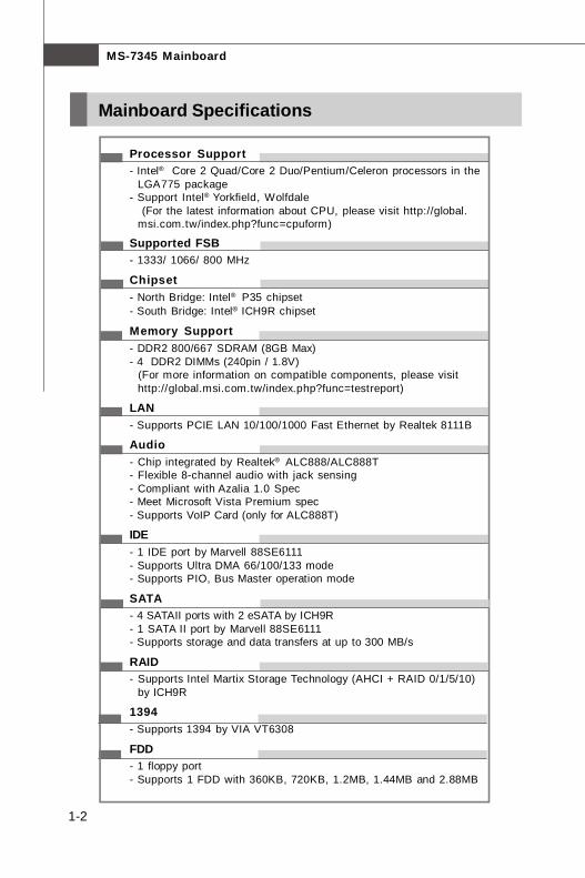
Processor Support- Intel® Core 2 Quad/Core 2 Duo/Pentium/Celeron processors in the
LGA775 package- Support Intel® Yorkfield, Wolfdale (For the latest information about CPU, please visit http://global.
msi.com.tw/index.php?func=cpuform)
Supported FSB- 1333/ 1066/ 800 MHz
Chipset- North Bridge: Intel® P35 chipset- South Bridge: Intel® ICH9R chipset
Memory Support- DDR2 800/667 SDRAM (8GB Max)- 4 DDR2 DIMMs (240pin / 1.8V) (For more information on compatible components, please visit
http://global.msi.com.tw/index.php?func=testreport)
LAN- Supports PCIE LAN 10/100/1000 Fast Ethernet by Realtek 8111B
Audio- Chip integrated by Realtek® ALC888/ALC888T- Flexible 8-channel audio with jack sensing- Compliant with Azalia 1.0 Spec- Meet Microsoft Vista Premium spec- Supports VoIP Card (only for ALC888T)
IDE- 1 IDE port by Marvell 88SE6111- Supports Ultra DMA 66/100/133 mode- Supports PIO, Bus Master operation mode
SATA- 4 SATAII ports with 2 eSATA by ICH9R- 1 SATA II port by Marvell 88SE6111- Supports storage and data transfers at up to 300 MB/s
RAID- Supports Intel Martix Storage Technology (AHCI + RAID 0/1/5/10)
by ICH9R
1394- Supports 1394 by VIA VT6308
FDD- 1 floppy port- Supports 1 FDD with 360KB, 720KB, 1.2MB, 1.44MB and 2.88MB
7345v1.0-1.p65 2007/5/11, 下午 02:022
1-3
Getting Started
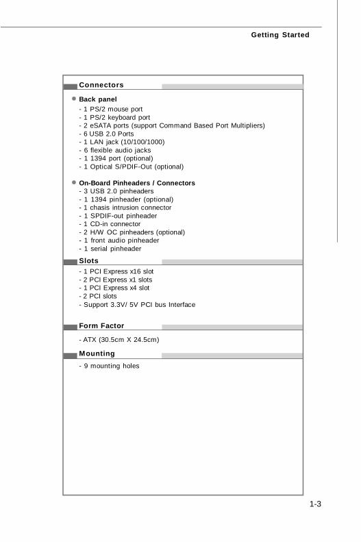
Connectors
Back panel- 1 PS/2 mouse port- 1 PS/2 keyboard port- 2 eSATA ports (support Command Based Port Multipliers)- 6 USB 2.0 Ports- 1 LAN jack (10/100/1000)- 6 flexible audio jacks- 1 1394 port (optional)- 1 Optical S/PDIF-Out (optional)
On-Board Pinheaders / Connectors- 3 USB 2.0 pinheaders- 1 1394 pinheader (optional)- 1 chasis intrusion connector- 1 SPDIF-out pinheader- 1 CD-in connector- 2 H/W OC pinheaders (optional)- 1 front audio pinheader- 1 serial pinheader
Slots- 1 PCI Express x16 slot- 2 PCI Express x1 slots- 1 PCI Express x4 slot- 2 PCI slots- Support 3.3V/ 5V PCI bus Interface
Form Factor
- ATX (30.5cm X 24.5cm)
Mounting- 9 mounting holes
7345v1.0-1.p65 2007/5/11, 下午 02:023
MS-7345 Mainboard
1-4
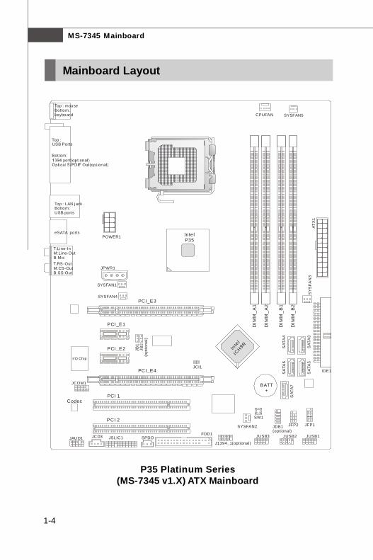
P35 Platinum Series(MS-7345 v1.X) ATX Mainboard
Mainboard Layout
DIM
M_A
1
DIM
M_B
1
DIM
M_A
2
DIM
M_B
2
Inte lP35
PCI 2
PCI 1
PCI_E2
Codec
I/O Chip
PCI_E1
PCI_E3
BATT+
JAUD1
CPUFAN
POWER1
JPWR1
SYSFAN1
SY
SFA
N3
SYSFAN2
J1394_1(optional)
JCOM1
FDD1JCD3 SPDO JUSB3 JUSB2 JUSB1
JDB1(optional)
JFP2 JFP1
SAT
A7
SA
TA6
SA
TA5
SAT
A4
SAT
A3
IDE1
ATX
1
Top : mouse Bottom:keyboard
Top : LAN jackBottom:USB ports
eSATA ports
T:M:B:
Line-InLine-OutMic
T:RS-OutM:CS-OutB:SS-Out
JCI1
Top : USB Ports
Bottom:
Inte
l IC
H9R
SW1
PCI_E4
JSLIC1
SYSFAN4
SYSFAN5
JB1
JB2
(opt
iona
l)
7345v1.0-1.p65 2007/5/11, 下午 02:024
1-5
Getting Started
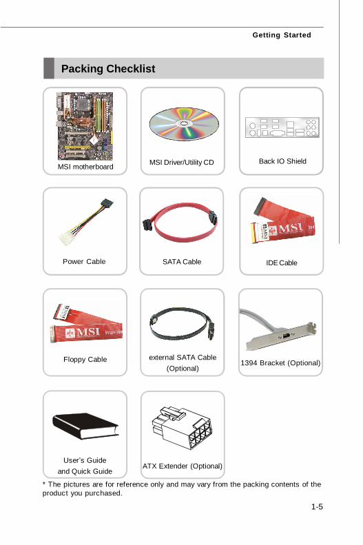
Packing Checklist
* The pictures are for reference only and may vary from the packing contents of theproduct you purchased.
Power Cable
User’s Guideand Quick Guide
MSI motherboard MSI Driver/Utility CD
Floppy Cable
IDE Cable
Back IO Shield
1394 Bracket (Optional)
SATA Cable
external SATA Cable(Optional)
ATX Extender (Optional)
7345v1.0-1.p65 2007/5/11, 下午 02:025
2-1
Hardware Setup
Hardware SetupChapter 2
This chapter provides you with the information abouthardware setup procedures. While doing the installation,be careful in holding the components and follow theinstallation procedures. For some components, if youinstall in the wrong orientation, the components will notwork properly.
Use a grounded wrist strap before handling computercomponents. S tatic elec tr ic ity may damage thecomponents.
7345v1.0CH2 Hardware Setup.p65 2007/5/11, 下午 02:021
MS-7345 Mainboard
2-2
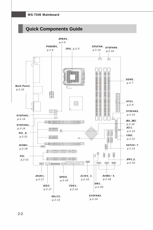
Quick Components Guide
CPU, p.2-3CPUFAN,
p.2-14
DDR2, p.2-7
ATX1, p.2-9
SYSFAN3,
p.2-14
IDE1,
p.2-12
SATA3~7,
p.2-13
JFP1,2, p.2-16
JUSB1~3, p.2-18
SYSFAN2, p.2-14
J1394_1,
p.2-15
FDD1,
p.2-12
SPDO, p.2-15
JCD3,
p.2-17
JAUD1,
p.2-17
PCI,
p.2-21
JCOM1,
p.2-18
PCI_E,
p.2-21
SYSFAN1,
p.2-14
Back Panel,
p.2-10
POWER1,
p.2-9
JPWR1, p.2-9
JCI1,
p.2-14
SW1, p.2-20
SYSFAN5, p.2-14
SYSFAN4, p.2-14
JSLIC1,
p.2-13
JB1,JB2, p.2-19
7345v1.0CH2 Hardware Setup.p65 2007/5/11, 下午 02:022
2-3
Hardware Setup
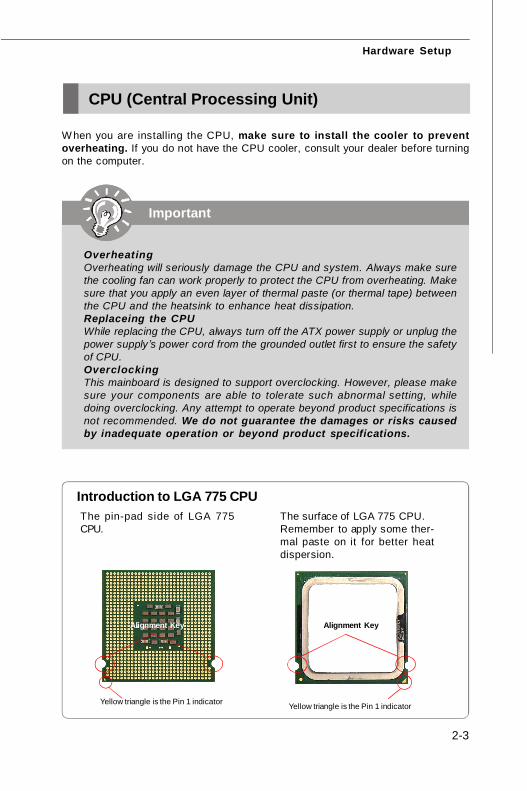
CPU (Central Processing Unit)
W hen you are installing the CPU, make sure to install the cooler to preventoverheating. If you do not have the CPU cooler, consult your dealer before turningon the computer.
Introduction to LGA 775 CPUThe surface of LGA 775 CPU.Remember to apply some ther-mal paste on it for better heatdispersion.
Yellow triangle is the Pin 1 indicator
The pin-pad side of LGA 775CPU.
Yellow triangle is the Pin 1 indicator
Alignment Key Alignment Key
Important
OverheatingOverheating will seriously damage the CPU and system. Always make surethe cooling fan can work properly to protect the CPU from overheating. Makesure that you apply an even layer of thermal paste (or thermal tape) betweenthe CPU and the heatsink to enhance heat dissipation.Replaceing the CPUWhile replacing the CPU, always turn off the ATX power supply or unplug thepower supply’s power cord from the grounded outlet first to ensure the safetyof CPU.OverclockingThis mainboard is designed to support overclocking. However, please makesure your components are able to tolerate such abnormal setting, whiledoing overclocking. Any attempt to operate beyond product specifications isnot recommended. We do not guarantee the damages or risks causedby inadequate operation or beyond product specifications.
7345v1.0CH2 Hardware Setup.p65 2007/5/11, 下午 02:023
MS-7345 Mainboard
2-4
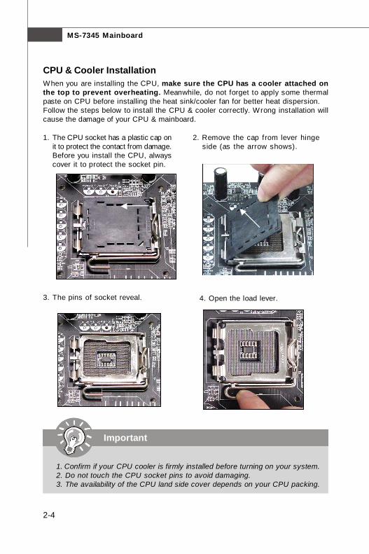
Important
1. Confirm if your CPU cooler is firmly installed before turning on your system.2. Do not touch the CPU socket pins to avoid damaging.3. The availability of the CPU land side cover depends on your CPU packing.
2. Remove the cap from lever hingeside (as the arrow shows).
1. The CPU socket has a plastic cap onit to protect the contact from damage.Before you install the CPU, alwayscover it to protect the socket pin.
3. The pins of socket reveal.
CPU & Cooler InstallationWhen you are installing the CPU, make sure the CPU has a cooler attached onthe top to prevent overheating. Meanwhile, do not forget to apply some thermalpaste on CPU before installing the heat sink/cooler fan for better heat dispersion.Follow the steps below to install the CPU & cooler correctly. Wrong installation willcause the damage of your CPU & mainboard.
4. Open the load lever.
7345v1.0CH2 Hardware Setup.p65 2007/5/11, 下午 02:024
2-5
Hardware Setup
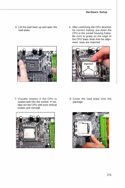
6. After confirming the CPU directionfor correct mating, put down theCPU in the socket housing frame.Be sure to grasp on the edge ofthe CPU base. Note that the align-ment keys are matched.
8. Cover the load plate onto thepackage.
7. Visually inspect if the CPU isseated well into the socket. If not,take out the CPU with pure verticalmotion and reinstall.
alignmentkey
5. Lift the load lever up and open theload plate.
7345v1.0CH2 Hardware Setup.p65 2007/5/11, 下午 02:025
MS-7345 Mainboard
2-6
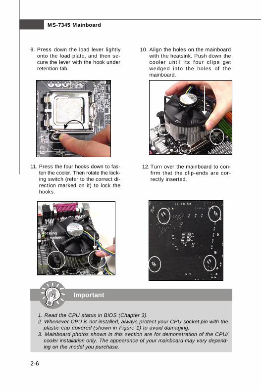
10. Align the holes on the mainboardwith the heatsink. Push down thecooler unti l i ts four c lips getwedged into the holes of themainboard.
12. Turn over the mainboard to con-firm that the clip-ends are cor-rectly inserted.
11. Press the four hooks down to fas-ten the cooler. Then rotate the lock-ing switch (refer to the correct di-rection marked on it) to lock thehooks.
9. Press down the load lever lightlyonto the load plate, and then se-cure the lever with the hook underretention tab.
lockingswitch
Important
1. Read the CPU status in BIOS (Chapter 3).2. Whenever CPU is not installed, always protect your CPU socket pin with the
plastic cap covered (shown in Figure 1) to avoid damaging.3. Mainboard photos shown in this section are for demonstration of the CPU/
cooler installation only. The appearance of your mainboard may vary depend-ing on the model you purchase.
7345v1.0CH2 Hardware Setup.p65 2007/5/11, 下午 02:026
2-7
Hardware Setup
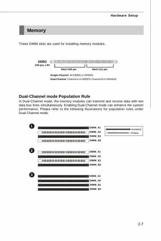
Memory
Dual-Channel mode Population RuleIn Dual-Channel mode, the memory modules can transmit and receive data with twodata bus lines simultaneously. Enabling Dual-Channel mode can enhance the systemperformance. Please refer to the following illustrations for population rules underDual-Channel mode.
64x2=128 pin 56x2=112 pin
DDR2240-pin, 1.8V
Single-Channel: All DIMMs in GREENDual-Channel: Channel A in GREEN; Channel B in ORANGE
1 DIMM_A1
DIMM_A2 DIMM_B1
DIMM_B2
2 DIMM_A1
DIMM_A2 DIMM_B1
DIMM_B2
3 DIMM_A1
DIMM_A2 DIMM_B1
DIMM_B2
These DIMM slots are used for installing memory modules.
EmptyInstalled
7345v1.0CH2 Hardware Setup.p65 2007/5/11, 下午 02:027
MS-7345 Mainboard
2-8
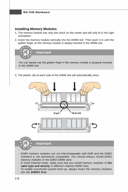
Installing Memory Modules1. The memory module has only one notch on the center and will only fit in the right
orientation.2. Insert the memory module vertically into the DIMM slot. Then push it in until the
golden finger on the memory module is deeply inserted in the DIMM slot.
3. The plastic clip at each side of the DIMM slot will automatically close.
Important
You can barely see the golden finger if the memory module is properly insertedin the DIMM slot.
Volt Notch
Important
- DDR2 memory modules are not interchangeable with DDR and the DDR2standard is not backwards compatible. You should always install DDR2memory modules in the DDR2 DIMM slots.
- In Dual-Channel mode, make sure that you install memory modules of thesame type and density in different channel DIMM slots.
- To enable successful system boot-up, always insert the memory modulesinto the DIMM1 first.
7345v1.0CH2 Hardware Setup.p65 2007/5/11, 下午 02:028

2-9
Hardware Setup
Power Supply
PIN SIGNAL
13 +3.3V14 -12V15 GND16 PS-ON#17 GND18 GND19 GND20 Res21 +5V22 +5V23 +5V24 GND
PIN SIGNAL
1 +3.3V 2 +3.3V 3 GND 4 +5V 5 GND 6 +5V 7 GND 8 PWR OK 9 5VSB10 +12V11 +12V12 +3.3V
Pin Definitionpin 12
pin 13
1
ATX1
1224
13
Important
1. Make sure that all the connectors are connected to proper ATX power sup-plies to ensure stable operation of the mainboard.
2. Power supply of 350 watts (and above) is highly recommended for systemstability.
3. ATX 12V power connection should be greater than 18A.4. If the POWER1 connector too closes the heatpipe and plug inconveniently.
You could use the bundled ATX Extender to increase connector height. It canprevent the power cable to touch the heatpipe as well.
ATX 24-Pin Power Connector: ATX1This connector allows you to connect an ATX 24-pin power supply.To connect the ATX 24-pin power supply, make sure the plug of thepower supply is inserted in the proper orientation and the pins arealigned. Then push down the power supply firmly into the connector.You may use the 20-pin ATX power supply as you like. If you’d liketo use the 20-pin ATX power supply, please plug your power sup-ply along with pin 1 & pin 13 (refer to the image at the right hand).
POWER1
PIN SIGNAL
1 5V2 GND3 GND4 12V
Pin Definition1
JPWR1
PIN SIGNAL
5 +12V6 +12V7 +12V8 +12V
PIN SIGNAL
1 GND2 GND3 GND4 GND
Pin Definition
ATX 12V Power Connector: POWER1 / JPWR1The POWER1 12V power connector is used to provide power to the CPU. And theJPWR1 12V power connector is used to provide power to the PCIEX16 graphicscard.
1
8
5
4
7345v1.0CH2 Hardware Setup.p65 2007/5/11, 下午 02:029
MS-7345 Mainboard
2-10
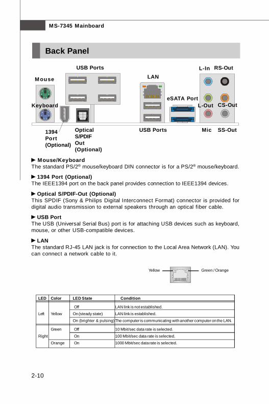
Green / OrangeYellow
LED Color LED State Condition
Off LAN link is not established.
Left Yellow On (steady state) LAN link is established.
On (brighter & pulsing) The computer is communicating with another computer on the LAN.
Green Off 10 Mbit/sec data rate is selected.
Right On 100 Mbit/sec data rate is selected.
Orange On 1000 Mbit/sec data rate is selected.
Back Panel
Mouse/KeyboardThe standard PS/2® mouse/keyboard DIN connector is for a PS/2® mouse/keyboard.
1394 Port (Optional)The IEEE1394 port on the back panel provides connection to IEEE1394 devices.
Optical S/PDIF-Out (Optional)This SPDIF (Sony & Philips Digital Interconnect Format) connector is provided fordigital audio transmission to external speakers through an optical fiber cable.
USB PortThe USB (Universal Serial Bus) port is for attaching USB devices such as keyboard,mouse, or other USB-compatible devices.
LANThe standard RJ-45 LAN jack is for connection to the Local Area Network (LAN). Youcan connect a network cable to it.
Keyboard
USB Ports Mic
L-Out
L-In
Mouse LANRS-Out
SS-Out
CS-Out
USB Ports
eSATA Port
1394Port(Optional)
OpticalS/PDIFOut(Optional)
7345v1.0CH2 Hardware Setup.p65 2007/5/11, 下午 02:0210

2-11
Hardware Setup
Audio PortsThese audio connectors are used for audio devices. You can differentiate the colorof the audio jacks for different audio sound effects.
Line-In (Blue) - Line In is used for external CD player, tapeplayer orother audio devices.
Line-Out (Green) - Line Out, is a connector for speakers or headphones. Mic (Pink) - Mic, is a connector for microphones. RS-Out (Black) - Rear-Surround Out in 4/ 5.1/ 7.1 channel mode. CS-Out (Orange) - Center/ Subwoofer Out in 5.1/ 7.1 channel mode. SS-Out (Gray) - Side-Surround Out 7.1 channel mode.
eSATA PortThe eSATA port is for attaching the eSATA external hard drive.
7345v1.0CH2 Hardware Setup.p65 2007/5/11, 下午 02:0211
MS-7345 Mainboard
2-12
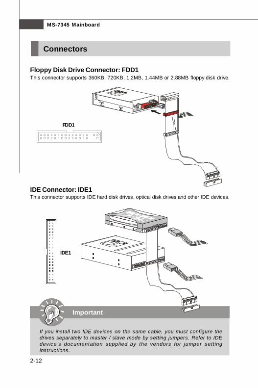
Connectors
Floppy Disk Drive Connector: FDD1This connector supports 360KB, 720KB, 1.2MB, 1.44MB or 2.88MB floppy disk drive.
FDD1
IDE Connector: IDE1This connector supports IDE hard disk drives, optical disk drives and other IDE devices.
IDE1
Important
If you install two IDE devices on the same cable, you must configure thedrives separately to master / slave mode by setting jumpers. Refer to IDEdevice ’s documentation supplied by the vendors for jumper sett inginstructions.
7345v1.0CH2 Hardware Setup.p65 2007/5/11, 下午 02:0212
2-13
Hardware Setup
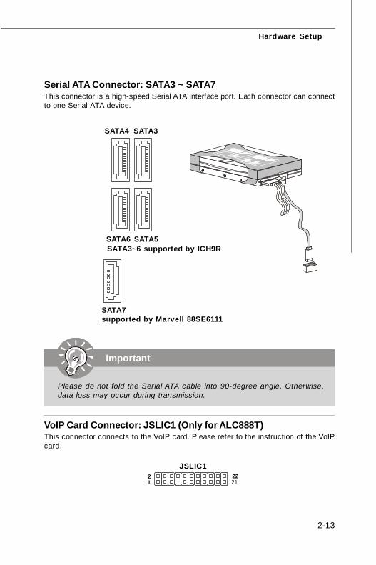
Serial ATA Connector: SATA3 ~ SATA7This connector is a high-speed Serial ATA interface port. Each connector can connectto one Serial ATA device.
SATA3SATA4
SATA5SATA6
Important
Please do not fold the Serial ATA cable into 90-degree angle. Otherwise,data loss may occur during transmission.
SATA7supported by Marvell 88SE6111
VoIP Card Connector: JSLIC1 (Only for ALC888T)This connector connects to the VoIP card. Please refer to the instruction of the VoIPcard.
JSLIC1
1 2
21 22
SATA3~6 supported by ICH9R
7345v1.0CH2 Hardware Setup.p65 2007/5/11, 下午 02:0213
MS-7345 Mainboard
2-14
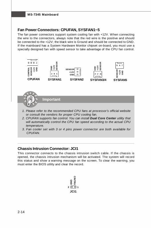
Chassis Intrusion Connector: JCI1This connector connects to the chassis intrusion switch cable. If the chassis isopened, the chassis intrusion mechanism will be activated. The system will recordthis status and show a warning message on the screen. To clear the warning, youmust enter the BIOS utility and clear the record.
JCI12
GN
DC
INTR
U
1
Fan Power Connectors: CPUFAN, SYSFAN1~5The fan power connectors support system cooling fan with +12V. When connectingthe wire to the connectors, always note that the red wire is the positive and shouldbe connected to the +12V; the black wire is Ground and should be connected to GND.If the mainboard has a System Hardware Monitor chipset on-board, you must use aspecially designed fan with speed sensor to take advantage of the CPU fan control.
CPUFAN SYSFAN2
SENSOR+12VGND
SYSFAN1
SE
NS
OR
+12V
GN
D
Important
1. Please refer to the recommended CPU fans at processor’s official websiteor consult the vendors for proper CPU cooling fan.
2. CPUFAN supports fan control. You can install Dual Core Center utility thatwill automatically control the CPU fan speed according to the actual CPUtemperature.
3. Fan cooler set with 3 or 4 pins power connector are both available forCPUFAN.
SE
NS
OR
+12V
GN
D
CO
NTR
OL
SYSFAN3/4
SE
NS
OR
+12V
GN
D
SYSFAN5
SE
NS
OR
+12V
GN
D
7345v1.0CH2 Hardware Setup.p65 2007/5/11, 下午 02:0214
2-15
Hardware Setup
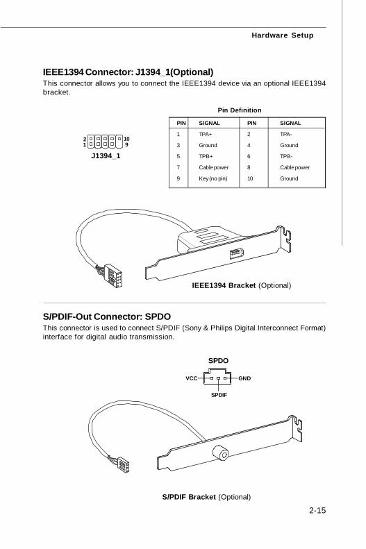
IEEE1394 Connector: J1394_1(Optional)This connector allows you to connect the IEEE1394 device via an optional IEEE1394bracket.
Pin Definition
PIN SIGNAL PIN SIGNAL
1 TPA+ 2 TPA-
3 Ground 4 Ground
5 TPB+ 6 TPB-
7 Cable power 8 Cable power
9 Key (no pin) 10 Ground
J1394_1 1 2
9 10
IEEE1394 Bracket (Optional)
S/PDIF Bracket (Optional)
S/PDIF-Out Connector: SPDOThis connector is used to connect S/PDIF (Sony & Philips Digital Interconnect Format)interface for digital audio transmission.
SPDO
VCC
SPDIF
GND
7345v1.0CH2 Hardware Setup.p65 2007/5/11, 下午 02:0215
MS-7345 Mainboard
2-16
PIN SIGNAL DESCRIPTION
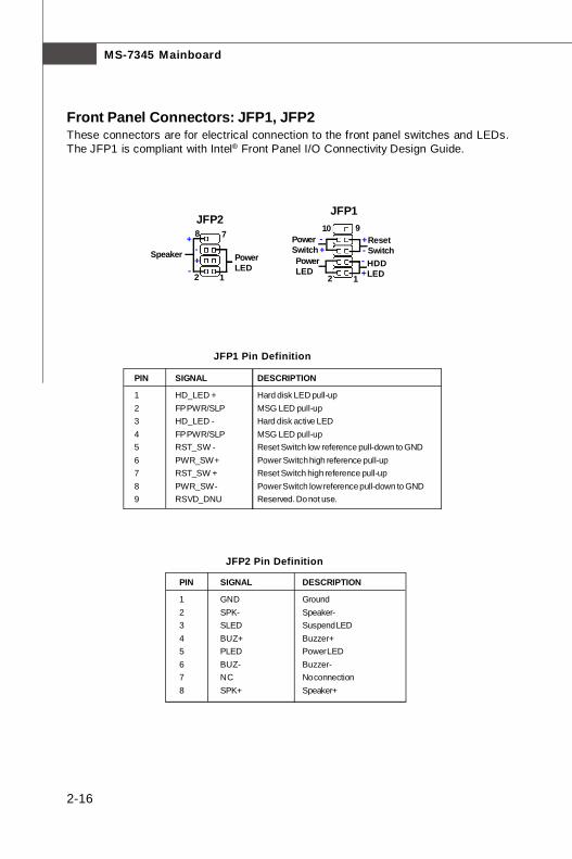
1 HD_LED + Hard disk LED pull-up2 FP PWR/SLP MSG LED pull-up3 HD_LED - Hard disk active LED4 FP PWR/SLP MSG LED pull-up5 RST_SW - Reset Switch low reference pull-down to GND6 PWR_SW + Power Switch high reference pull-up7 RST_SW + Reset Switch high reference pull-up8 PWR_SW - Power Switch low reference pull-down to GND9 RSVD_DNU Reserved. Do not use.
JFP1 Pin Definition
Front Panel Connectors: JFP1, JFP2These connectors are for electrical connection to the front panel switches and LEDs.The JFP1 is compliant with Intel® Front Panel I/O Connectivity Design Guide.
12
910
JFP1
HDDLED
ResetSwitch
PowerLED
PowerSwitch
+
++
--
-78
PowerLED
Speaker
12
JFP2+
+-
-
PIN SIGNAL DESCRIPTION
1 GND Ground2 SPK- Speaker-3 SLED Suspend LED4 BUZ+ Buzzer+5 PLED Power LED6 BUZ- Buzzer-7 NC No connection8 SPK+ Speaker+
JFP2 Pin Definition
7345v1.0CH2 Hardware Setup.p65 2007/5/11, 下午 02:0216
2-17
Hardware Setup
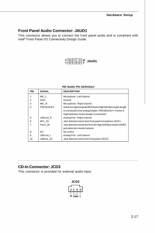
Front Panel Audio Connector: JAUD1This connector allows you to connect the front panel audio and is compliant withIntel® Front Panel I/O Connectivity Design Guide.
JAUD112
910
PIN SIGNAL DESCRIPTION
1 MIC_L Microphone - Left channel2 GND Ground3 MIC_R Microphone - Right channel4 PRESENCE# Active low signal-signals BIOS that a High Definition Audio dongle
is connected to the analog header. PRESENCE# = 0 when aHigh Definition Audio dongle is connected
5 LINE out_R Analog Port - Right channel6 MIC_JD Jack detection return from front panel microphone JACK17 Front_JD Jack detection sense line from the High Definition Audio CODEC
jack detection resistor network8 NC No control9 LINE out_L Analog Port - Left channel10 LINEout_JD Jack detection return from front panel JACK2
HD Audio Pin Definition
CD-In Connector: JCD3This connector is provided for external audio input.
JCD3
GNDR L
7345v1.0CH2 Hardware Setup.p65 2007/5/11, 下午 02:0217
MS-7345 Mainboard
2-18
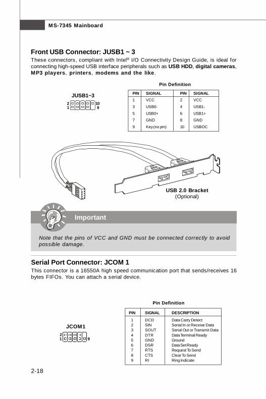
Front USB Connector: JUSB1 ~ 3These connectors, compliant with Intel® I/O Connectivity Design Guide, is ideal forconnecting high-speed USB interface peripherals such as USB HDD, digital cameras,MP3 players, printers, modems and the like.
12
910
JUSB1~3 PIN SIGNAL PIN SIGNAL1 VCC 2 VCC
3 USB0- 4 USB1-
5 USB0+ 6 USB1+7 GND 8 GND
9 Key (no pin) 10 USBOC
Pin Definition
Important
Note that the pins of VCC and GND must be connected correctly to avoidpossible damage.
USB 2.0 Bracket(Optional)
Serial Port Connector: JCOM 1This connector is a 16550A high speed communication port that sends/receives 16bytes FIFOs. You can attach a serial device.
PIN SIGNAL DESCRIPTION
1 DCD Data Carry Detect 2 SIN Serial In or Receive Data 3 SOUT Serial Out or Transmit Data 4 DTR Data Terminal Ready 5 GND Ground 6 DSR Data Set Ready 7 RTS Request To Send 8 CTS Clear To Send 9 RI Ring Indicate
Pin Definition
JCOM1
1 92
7345v1.0CH2 Hardware Setup.p65 2007/5/11, 下午 02:0218
2-19
Hardware Setup
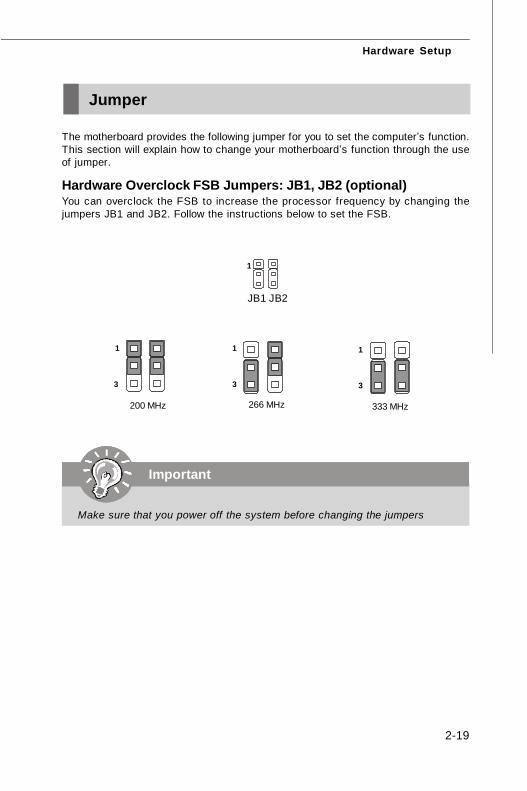
The motherboard provides the following jumper for you to set the computer’s function.This section will explain how to change your motherboard’s function through the useof jumper.
Hardware Overclock FSB Jumpers: JB1, JB2 (optional)You can overclock the FSB to increase the processor frequency by changing thejumpers JB1 and JB2. Follow the instructions below to set the FSB.
Jumper
Important
Make sure that you power off the system before changing the jumpers
1
266 MHz
1
3
200 MHz
1
3
JB1 JB2
333 MHz
1
3
7345v1.0CH2 Hardware Setup.p65 2007/5/11, 下午 02:0219
MS-7345 Mainboard
2-20
The motherboard provides the following button for you to set the computer’s function.This section will explain how to change your motherboard’s function through the useof button.
Clear CMOS Button: SW1There is a CMOS RAM on board that has a power supply from external battery tokeep the system configuration data. With the CMOS RAM, the system can automati-cally boot OS every time it is turned on. If you want to clear the system configuration,use the button to clear data. Press the button to clear the data.
SW1
Button
Important
Make sure that you power off the system before clearing CMOS data.
7345v1.0CH2 Hardware Setup.p65 2007/5/11, 下午 02:0220
2-21
Hardware Setup
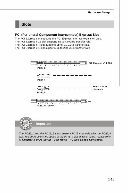
PCI (Peripheral Component Interconnect) Express SlotThe PCI Express slot supports the PCI Express interface expansion card.The PCI Express x 16 slot supports up to 4.0 GB/s transfer rate.The PCI Express x 4 slot supports up to 1.0 GB/s transfer rate.The PCI Express x 1 slot supports up to 250 MB/s transfer rate.
Slots
PCI Express x16 Slot
PCIE_1
Important
The PCIE_1 and the PCIE_2 slots share 4 PCIE channels with the PCIE_4slot. You could select the speed of the PCIE_4 slot in BIOS setup. Please referto Chapter 3 BIOS Setup - Cell Menu - PCIEx4 Speed Controller.
PCIE_2
PCIE_4 (Yellow)
PCIE_3
Share 4 PCIEchannels
7345v1.0CH2 Hardware Setup.p65 2007/5/11, 下午 02:0221
MS-7345 Mainboard
2-22
PCI Interrupt Request RoutingThe IRQ, acronym of interrupt request line and pronounced I-R-Q, are hardware linesover which devices can send interrupt signals to the microprocessor. The PCI IRQpins are typically connected to the PCI bus pins as follows:
Order 1 Order 2 Order 3 Order 4
PCI Slot 1 INT A# INT B# INT C# INT D#
PCI Slot 2 INT B# INT C# INT D# INT A#
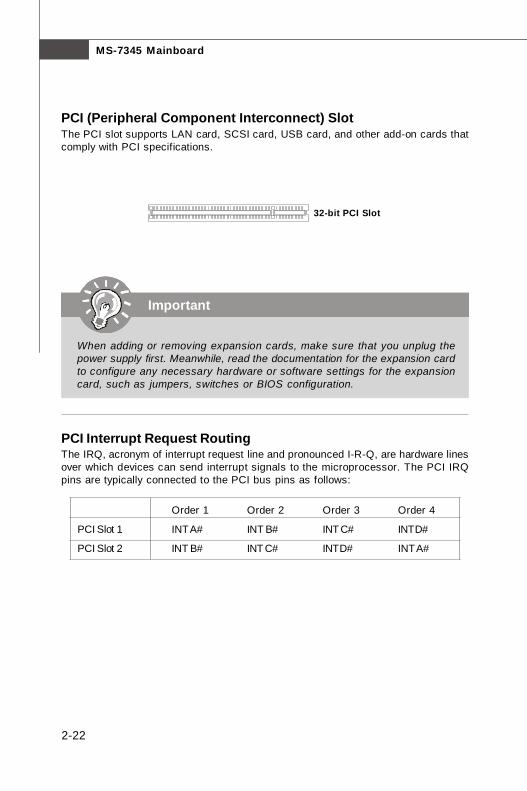
32-bit PCI Slot
Important
When adding or removing expansion cards, make sure that you unplug thepower supply first. Meanwhile, read the documentation for the expansion cardto configure any necessary hardware or software settings for the expansioncard, such as jumpers, switches or BIOS configuration.
PCI (Peripheral Component Interconnect) SlotThe PCI slot supports LAN card, SCSI card, USB card, and other add-on cards thatcomply with PCI specifications.
7345v1.0CH2 Hardware Setup.p65 2007/5/11, 下午 02:0222
2-23
Hardware Setup
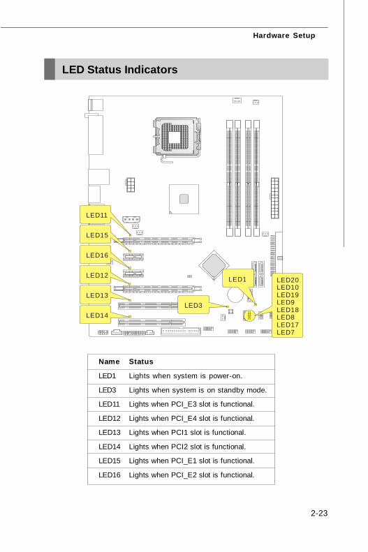
LED Status Indicators
Name Status
LED1 Lights when system is power-on.
LED3 Lights when system is on standby mode.
LED11 Lights when PCI_E3 slot is functional.
LED12 Lights when PCI_E4 slot is functional.
LED13 Lights when PCI1 slot is functional.
LED14 Lights when PCI2 slot is functional.
LED15 Lights when PCI_E1 slot is functional.
LED16 Lights when PCI_E2 slot is functional.
LED14
LED13
LED12
LED16
LED15
LED11
LED3
LED1 LED20LED10LED19LED9LED18LED8LED17LED7
7345v1.0CH2 Hardware Setup.p65 2007/5/11, 下午 02:0223
MS-7345 Mainboard
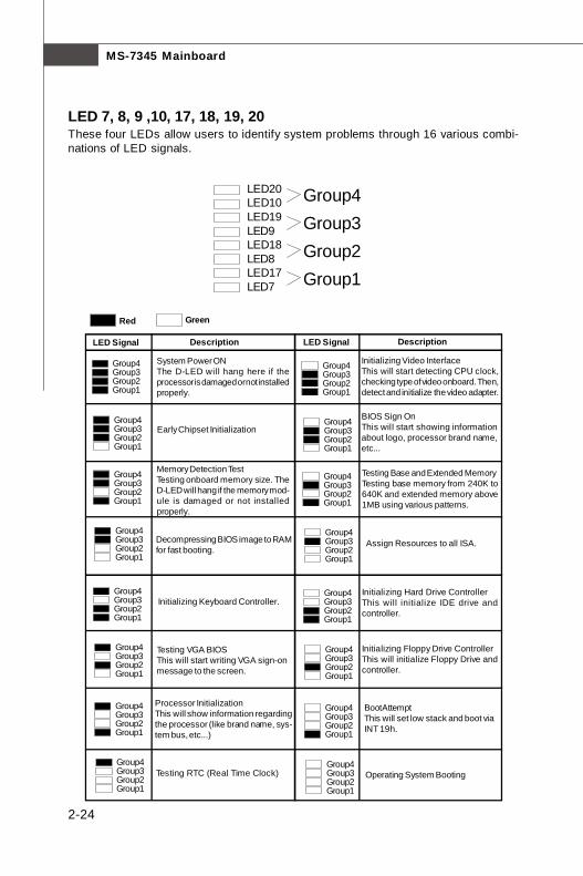
2-24
LED 7, 8, 9 ,10, 17, 18, 19, 20These four LEDs allow users to identify system problems through 16 various combi-nations of LED signals.
BIOS Sign OnThis will start showing informationabout logo, processor brand name,etc...
Testing Base and Extended MemoryTesting base memory from 240K to640K and extended memory above1MB using various patterns.
Assign Resources to all ISA.
Initializing Hard Drive ControllerThis will initialize IDE drive andcontroller.
Initializing Floppy Drive ControllerThis will initialize Floppy Drive andcontroller.
Boot AttemptThis will set low stack and boot viaINT 19h.
Operating System Booting
System Power ONThe D-LED will hang here if theprocessor is damaged or not installedproperly.
Initializing Keyboard Controller.
Testing VGA BIOSThis will start writing VGA sign-onmessage to the screen.
Processor InitializationThis will show information regardingthe processor (like brand name, sys-tem bus, etc...)
Testing RTC (Real Time Clock)
Description
Red Green
LED Signal DescriptionLED Signal
Early Chipset Initialization
Memory Detection TestTesting onboard memory size. TheD-LED will hang if the memory mod-ule is damaged or not installedproperly.
Decompressing BIOS image to RAMfor fast booting.
Initializing Video InterfaceThis will start detecting CPU clock,checking type of video onboard. Then,detect and initialize the video adapter.
LED20LED10LED19LED9LED18LED8LED17LED7 Group1
Group2Group3Group4
Group4Group3Group2Group1
Group4Group3Group2Group1
Group4Group3Group2Group1
Group4Group3Group2Group1
Group4Group3Group2Group1
Group4Group3Group2Group1
Group4Group3Group2Group1
Group4Group3Group2Group1
Group4Group3Group2Group1
Group4Group3Group2Group1
Group4Group3Group2Group1
Group4Group3Group2Group1
Group4Group3Group2Group1
Group4Group3Group2Group1
Group4Group3Group2Group1
Group4Group3Group2Group1
7345v1.0CH2 Hardware Setup.p65 2007/5/11, 下午 02:0224
3-1
BIOS Setup
Chapter 3
BIOS Setup
This chapter provides information on the BIOS Setupprogram and allows you to configure the system foroptimum use.You may need to run the Setup program when:
² An error message appears on the screen during thesystem booting up, and requests you to run SETUP.
² You want to change the default settings for cus-tomized features.
7345v1.0-3_BIOS.p65 2007/5/11, 下午 02:021
3-2
MS-7345 Mainboard
Entering Setup
Important
1. The items under each BIOS category described in this chapter are undercontinuous update for better system performance. Therefore, the descrip-tion may be slightly different from the latest BIOS and should be held forreference only.
2. Upon boot-up, the 1st line appearing after the memory count is the BIOSversion. It is usually in the format:
A7345IMS V1.0 030807 where:
1st digit refers to BIOS maker as A = AMI, W = AWARD, and P =PHOENIX.2nd - 5th digit refers to the model number.6th digit refers to the chipset as I = Intel, N = nVidia, and V = VIA.7th - 8th digit refers to the customer as MS = all standard customers.V1.1 refers to the BIOS version.030807 refers to the date this BIOS was released.
Power on the computer and the system will start POST (Power On Self Test) process.When the message below appears on the screen, press <DEL> key to enter Setup.
Press DEL to enter SETUP
If the message disappears before you respond and you still wish to enter Setup,restart the system by turning it OFF and On or pressing the RESET button. You mayalso restart the system by simultaneously pressing <Ctrl>, <Alt>, and <Delete> keys.
7345v1.0-3_BIOS.p65 2007/5/11, 下午 02:022
3-3
BIOS Setup
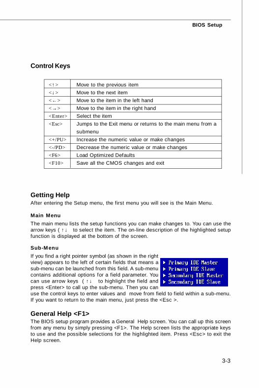
Getting HelpAfter entering the Setup menu, the first menu you will see is the Main Menu.
Main MenuThe main menu lists the setup functions you can make changes to. You can use thearrow keys ( ↑↓ ) to select the item. The on-line description of the highlighted setupfunction is displayed at the bottom of the screen.
Sub-MenuIf you find a right pointer symbol (as shown in the rightview) appears to the left of certain fields that means asub-menu can be launched from this field. A sub-menucontains additional options for a field parameter. Youcan use arrow keys ( ↑↓ ) to highlight the f ield andpress <Enter> to call up the sub-menu. Then you canuse the control keys to enter values and move from field to field within a sub-menu.If you want to return to the main menu, just press the <Esc >.
General Help <F1>The BIOS setup program provides a General Help screen. You can call up this screenfrom any menu by simply pressing <F1>. The Help screen lists the appropriate keysto use and the possible selections for the highlighted item. Press <Esc> to exit theHelp screen.
Control Keys
<↑> Move to the previous item<↓> Move to the next item<←> Move to the item in the left hand<→> Move to the item in the right hand<Enter> Select the item<Esc> Jumps to the Exit menu or returns to the main menu from a
submenu<+/PU> Increase the numeric value or make changes<-/PD> Decrease the numeric value or make changes<F6> Load Optimized Defaults<F10> Save all the CMOS changes and exit
7345v1.0-3_BIOS.p65 2007/5/11, 下午 02:023
3-4
MS-7345 Mainboard
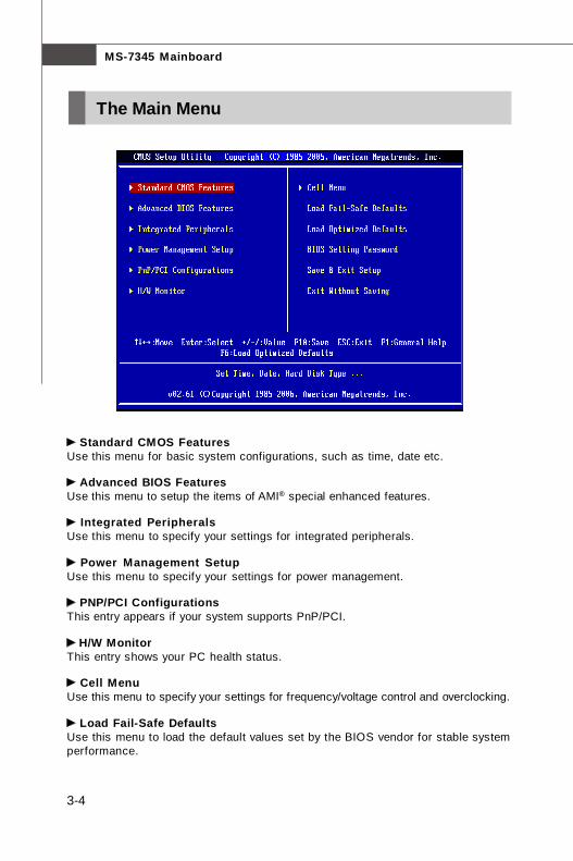
Standard CMOS FeaturesUse this menu for basic system configurations, such as time, date etc.
Advanced BIOS FeaturesUse this menu to setup the items of AMI® special enhanced features.
Integrated PeripheralsUse this menu to specify your settings for integrated peripherals.
Power Management SetupUse this menu to specify your settings for power management.
PNP/PCI ConfigurationsThis entry appears if your system supports PnP/PCI.
H/W MonitorThis entry shows your PC health status.
Cell MenuUse this menu to specify your settings for frequency/voltage control and overclocking.
Load Fail-Safe DefaultsUse this menu to load the default values set by the BIOS vendor for stable systemperformance.
The Main Menu
7345v1.0-3_BIOS.p65 2007/5/11, 下午 02:024
3-5
BIOS Setup
Load Optimized DefaultsUse this menu to load the default values set by the mainboard manufacturer specifi-cally for optimal performance of the mainboard.
BIOS Setting PasswordUse this menu to set the password for BIOS.
Save & Exit SetupSave changes to CMOS and exit setup.
Exit Without SavingAbandon all changes and exit setup.
7345v1.0-3_BIOS.p65 2007/5/11, 下午 02:025
3-6
MS-7345 Mainboard
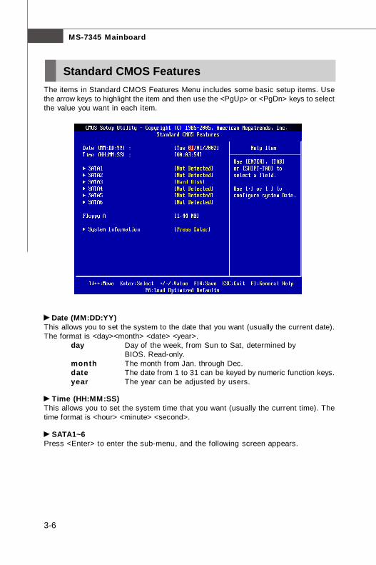
The items in Standard CMOS Features Menu includes some basic setup items. Usethe arrow keys to highlight the item and then use the <PgUp> or <PgDn> keys to selectthe value you want in each item.
Date (MM:DD:YY)This allows you to set the system to the date that you want (usually the current date).The format is <day><month> <date> <year>.
day Day of the week, from Sun to Sat, determined byBIOS. Read-only.
month The month from Jan. through Dec.date The date from 1 to 31 can be keyed by numeric function keys.year The year can be adjusted by users.
Time (HH:MM:SS)This allows you to set the system time that you want (usually the current time). Thetime format is <hour> <minute> <second>.
SATA1~6Press <Enter> to enter the sub-menu, and the following screen appears.
Standard CMOS Features
7345v1.0-3_BIOS.p65 2007/5/11, 下午 02:026
3-7
BIOS Setup
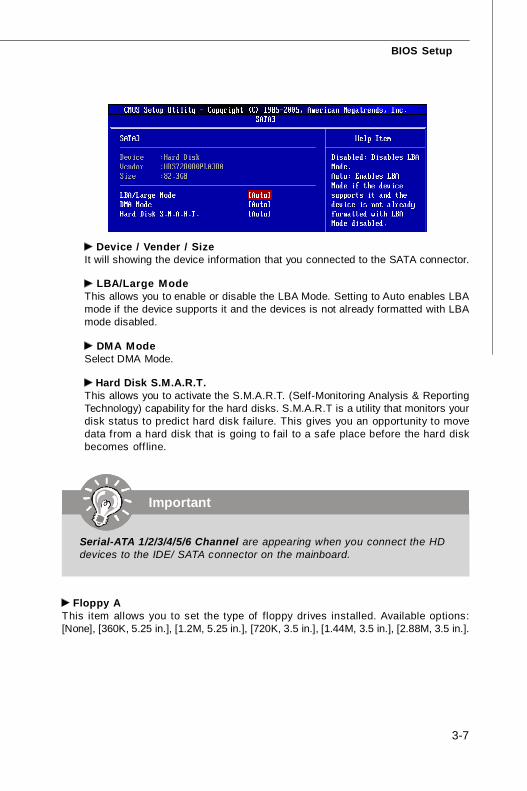
Device / Vender / SizeIt will showing the device information that you connected to the SATA connector.
LBA/Large ModeThis allows you to enable or disable the LBA Mode. Setting to Auto enables LBAmode if the device supports it and the devices is not already formatted with LBAmode disabled.
DMA ModeSelect DMA Mode.
Hard Disk S.M.A.R.T.This allows you to activate the S.M.A.R.T. (Self-Monitoring Analysis & ReportingTechnology) capability for the hard disks. S.M.A.R.T is a utility that monitors yourdisk status to predict hard disk failure. This gives you an opportunity to movedata from a hard disk that is going to fail to a safe place before the hard diskbecomes off line.
Important
Serial-ATA 1/2/3/4/5/6 Channel are appearing when you connect the HDdevices to the IDE/ SATA connector on the mainboard.
Floppy AThis item allows you to set the type of floppy drives installed. Available options:[None], [360K, 5.25 in.], [1.2M, 5.25 in.], [720K, 3.5 in.], [1.44M, 3.5 in.], [2.88M, 3.5 in.].
7345v1.0-3_BIOS.p65 2007/5/11, 下午 02:027
3-8
MS-7345 Mainboard
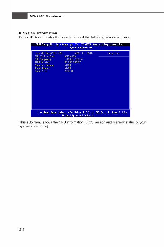
This sub-menu shows the CPU information, BIOS version and memory status of yoursystem (read only).
System InformationPress <Enter> to enter the sub-menu, and the following screen appears.
7345v1.0-3_BIOS.p65 2007/5/11, 下午 02:028
3-9
BIOS Setup
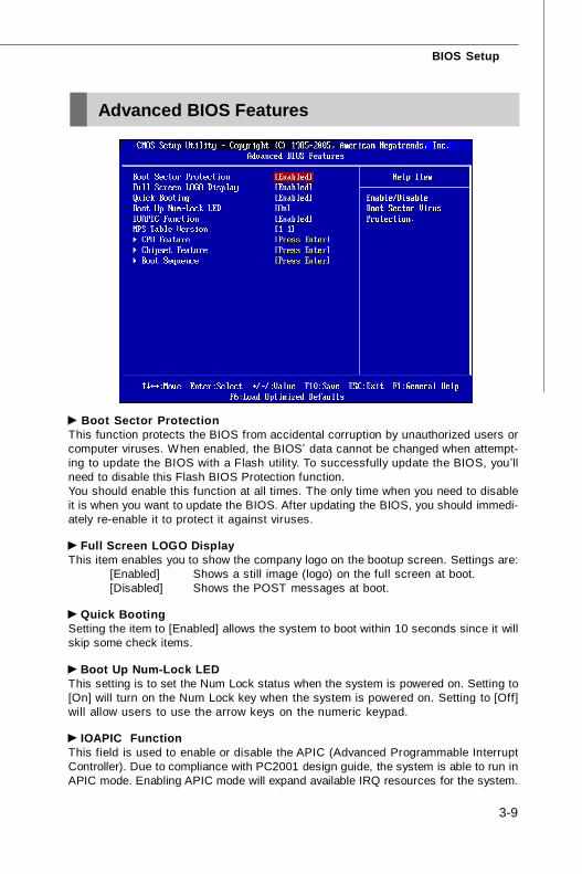
Boot Sector ProtectionThis function protects the BIOS from accidental corruption by unauthorized users orcomputer viruses. When enabled, the BIOS’ data cannot be changed when attempt-ing to update the BIOS with a Flash utility. To successfully update the BIOS, you’llneed to disable this Flash BIOS Protection function.You should enable this function at all times. The only time when you need to disableit is when you want to update the BIOS. After updating the BIOS, you should immedi-ately re-enable it to protect it against viruses.
Full Screen LOGO DisplayThis item enables you to show the company logo on the bootup screen. Settings are:
[Enabled] Shows a still image (logo) on the full screen at boot.[Disabled] Shows the POST messages at boot.
Quick BootingSetting the item to [Enabled] allows the system to boot within 10 seconds since it willskip some check items.
Boot Up Num-Lock LEDThis setting is to set the Num Lock status when the system is powered on. Setting to[On] will turn on the Num Lock key when the system is powered on. Setting to [Off]will allow users to use the arrow keys on the numeric keypad.
IOAPIC FunctionThis field is used to enable or disable the APIC (Advanced Programmable InterruptController). Due to compliance with PC2001 design guide, the system is able to run inAPIC mode. Enabling APIC mode will expand available IRQ resources for the system.
Advanced BIOS Features
7345v1.0-3_BIOS.p65 2007/5/11, 下午 02:029

3-10
MS-7345 Mainboard
MPS Table VersionThis field allows you to select which MPS (Multi-Processor Specification) version tobe used for the operating system. You need to select the MPS version supported byyour operating system. To find out which version to use, consult the vendor of youroperating system.
CPU FeaturePress <Enter> to enter the sub-menu and the following screen appears:
Hyper-Threading TechnologyThis field appears only when the CPU supports Hyper-Threading. The proces-sor uses Hyper-Threading technology to increase transaction rates and re-duces end-user response times. The technology treats the two cores inside theprocessor as two logical processors that can execute ins t ruct ionssimultaneously. In this way, the system performance is highly improved. If youdisable the function, the processor wil l use only one core to execute theinstructions.
Execute Bit SupportIntel's Execute Disable Bit functionality can prevent certain classes of malicious"buffer overflow" attacks when combined with a supporting operating system.This functionality allows the processor to classify areas in memory by whereapplication code can execute and where it cannot. When a malicious wormattempts to insert code in the buffer, the processor disables code execution,preventing damage or worm propagation.
Set Limit CPUID MaxVal to 3The Max CPUID Value Limit is designed to limit the listed speed of the processorto older operating systems.
Chipset FeaturePress <Enter> to enter the sub-menu and the following screen appears:
7345v1.0-3_BIOS.p65 2007/5/11, 下午 02:0210
3-11
BIOS Setup
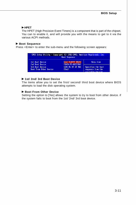
1st/ 2nd/ 3rd Boot DeviceThe items allow you to set the f irst/ second/ third boot device where BIOSattempts to load the disk operating system.
Boot From Other DeviceSetting the option to [Yes] allows the system to try to boot from other device. ifthe system fails to boot from the 1st/ 2nd/ 3rd boot device.
HPETThe HPET (High Precision Event Timers) is a component that is part of the chipset.You can to enable it, and will provide you with the means to get to it via thevarious ACPI methods.
Boot SequencePress <Enter> to enter the sub-menu and the following screen appears:
7345v1.0-3_BIOS.p65 2007/5/11, 下午 02:0211
3-12
MS-7345 Mainboard
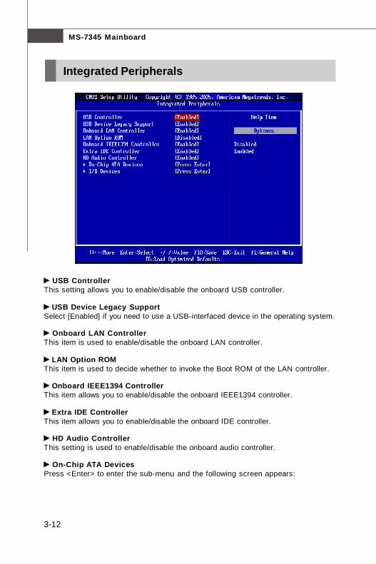
USB ControllerThis setting allows you to enable/disable the onboard USB controller.
USB Device Legacy SupportSelect [Enabled] if you need to use a USB-interfaced device in the operating system.
Onboard LAN ControllerThis item is used to enable/disable the onboard LAN controller.
LAN Option ROMThis item is used to decide whether to invoke the Boot ROM of the LAN controller.
Onboard IEEE1394 ControllerThis item allows you to enable/disable the onboard IEEE1394 controller.
Extra IDE ControllerThis item allows you to enable/disable the onboard IDE controller.
HD Audio ControllerThis setting is used to enable/disable the onboard audio controller.
On-Chip ATA DevicesPress <Enter> to enter the sub-menu and the following screen appears:
Integrated Peripherals
7345v1.0-3_BIOS.p65 2007/5/11, 下午 02:0312
3-13
BIOS Setup
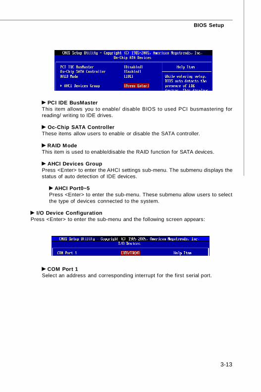
PCI IDE BusMasterThis item allows you to enable/ disable BIOS to used PCI busmastering forreading/ writing to IDE drives.
Oc-Chip SATA ControllerThese items allow users to enable or disable the SATA controller.
RAID ModeThis item is used to enable/disable the RAID function for SATA devices.
AHCI Devices GroupPress <Enter> to enter the AHCI settings sub-menu. The submenu displays thestatus of auto detection of IDE devices.
AHCI Port0~5Press <Enter> to enter the sub-menu. These submenu allow users to selectthe type of devices connected to the system.
I/O Device ConfigurationPress <Enter> to enter the sub-menu and the following screen appears:
COM Port 1Select an address and corresponding interrupt for the first serial port.
7345v1.0-3_BIOS.p65 2007/5/11, 下午 02:0313
3-14
MS-7345 Mainboard
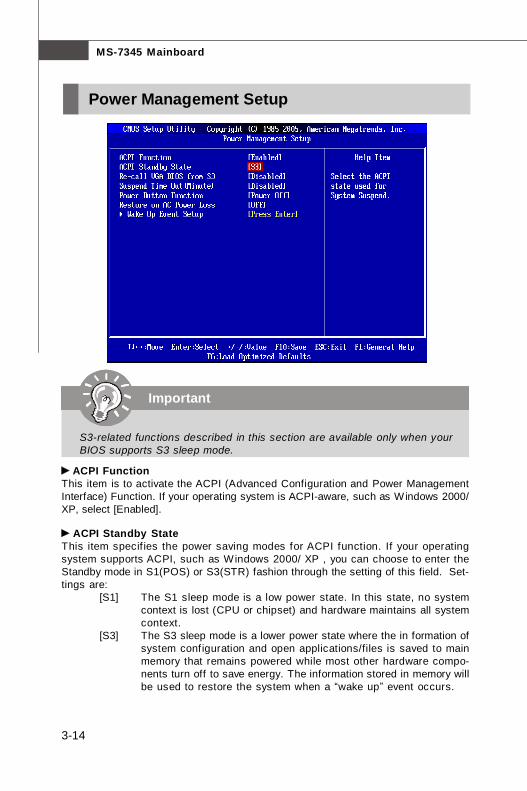
ACPI FunctionThis item is to activate the ACPI (Advanced Configuration and Power ManagementInterface) Function. If your operating system is ACPI-aware, such as Windows 2000/XP, select [Enabled].
ACPI Standby StateThis item specif ies the power saving modes for ACPI function. If your operatingsystem supports ACPI, such as Windows 2000/ XP , you can choose to enter theStandby mode in S1(POS) or S3(STR) fashion through the setting of this field. Set-tings are:
[S1] The S1 sleep mode is a low power state. In this state, no systemcontext is lost (CPU or chipset) and hardware maintains all systemcontext.
[S3] The S3 sleep mode is a lower power state where the in formation ofsystem configuration and open applications/files is saved to mainmemory that remains powered while most other hardware compo-nents turn off to save energy. The information stored in memory willbe used to restore the system when a “wake up” event occurs.
Important
S3-related functions described in this section are available only when yourBIOS supports S3 sleep mode.
Power Management Setup
7345v1.0-3_BIOS.p65 2007/5/11, 下午 02:0314
3-15
BIOS Setup
Re-Call VGA BIOS From S3When ACPI Standby State is set to [S3], users can select the options in this field.Selecting [Yes] allows BIOS to call VGABIOS to initialize the VGA card when systemwakes up (resumes) from S3 sleep state. The system resume time is shortenedwhen you disable the function, but system will need an VGA driver to initialize theVGA card. Therefore, if the VGA driver of the card does not support the initializationfeature, the display may work abnormally or not function after resuming from S3.
Suspend Time Out (Minute)If system activity is not detected for the length of time specified in this f ield, alldevices except CPU will be shut off.
Power Button FunctionThis feature sets the function of the power button. Settings are:
[On/ Off] The power button functions as normal power off button.[Suspend] When you press the power button, the computer enters the
suspend/sleep mode, but if the button is pressed for morethan four seconds, the computer is turned off.
Restore On AC Power LossThis item specifies whether your system will reboot after a power failure or interruptoccurs. Settings are:
[Off] Always leaves the computer in the power off state.[On] Always leaves the computer in the power on state.[Last State] Restores the system to the status before power failure
or interrupt occurred.
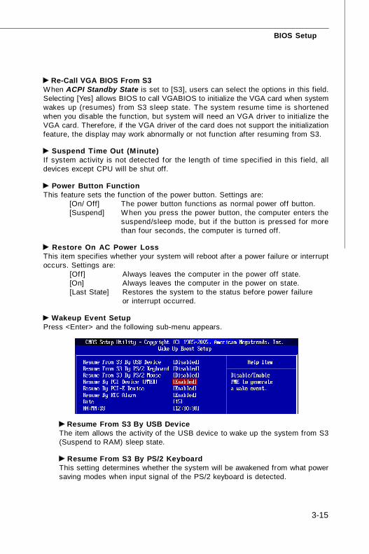
Wakeup Event SetupPress <Enter> and the following sub-menu appears.
Resume From S3 By USB DeviceThe item allows the activity of the USB device to wake up the system from S3(Suspend to RAM) sleep state.
Resume From S3 By PS/2 KeyboardThis setting determines whether the system will be awakened from what powersaving modes when input signal of the PS/2 keyboard is detected.
7345v1.0-3_BIOS.p65 2007/5/11, 下午 02:0315

3-16
MS-7345 Mainboard
Resume From S3 By PS/2 MouseThis setting determines whether the system will be awakened from what powersaving modes when input signal of the PS/2 mouse is detected.
Resume by PCI Device (PME#)When set to [Enabled], the feature allows your system to be awakened from thepower saving modes through any event on PME (Power Management Event).
Resume by PCI-E DeviceWhen set to [Enabled], the feature allows your system to be awakened from thepower saving modes through any event on PCIE device.
Resume by RTC AlarmThe field is used to enable or disable the feature of booting up the system on ascheduled time/date.
7345v1.0-3_BIOS.p65 2007/5/11, 下午 02:0316
3-17
BIOS Setup
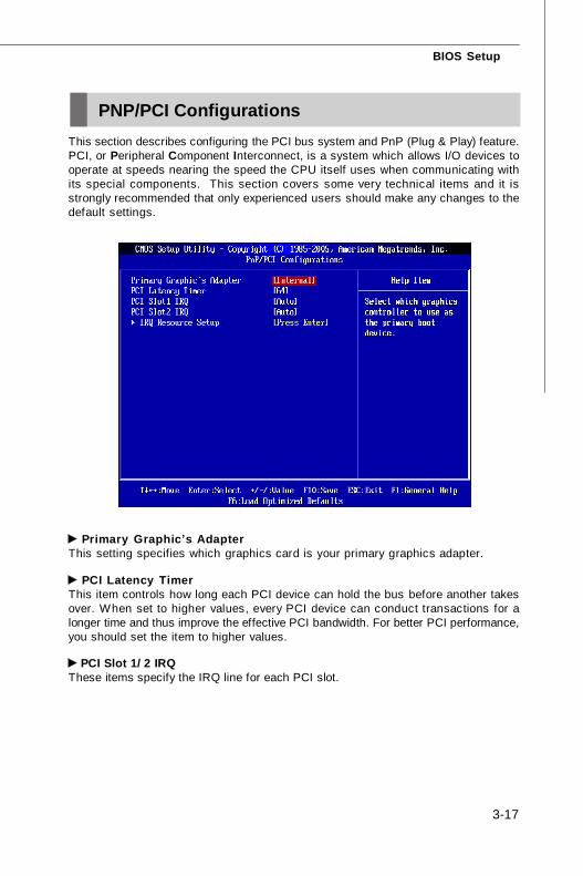
Primary Graphic’s AdapterThis setting specifies which graphics card is your primary graphics adapter.
PCI Latency TimerThis item controls how long each PCI device can hold the bus before another takesover. When set to higher values, every PCI device can conduct transactions for alonger time and thus improve the effective PCI bandwidth. For better PCI performance,you should set the item to higher values.
PCI Slot 1/ 2 IRQThese items specify the IRQ line for each PCI slot.
PNP/PCI ConfigurationsThis section describes configuring the PCI bus system and PnP (Plug & Play) feature.PCI, or Peripheral Component Interconnect, is a system which allows I/O devices tooperate at speeds nearing the speed the CPU itself uses when communicating withits special components. This section covers some very technical items and it isstrongly recommended that only experienced users should make any changes to thedefault settings.
7345v1.0-3_BIOS.p65 2007/5/11, 下午 02:0317

3-18
MS-7345 Mainboard
IRQ Resource SetupPress <Enter> to enter the sub-menu and the following screen appears.
IRQ 3/4/5/7/9/10/11/14/15These items specify the bus where the specified IRQ line is used.The settings determine if AMIBIOS should remove an IRQ from the pool of avail-able IRQs passed to devices that are configurable by the system BIOS. Theavailable IRQ pool is determined by reading the ESCD NVRAM. If more IRQs mustbe removed from the IRQ pool, the end user can use these settings to reservethe IRQ by assigning an [Reserved] setting to it. Onboard I/O is configured byAMIBIOS. All IRQs used by onboard I/O are configured as [Available]. If all IRQsare set to [Reserved], and IRQ 14/15 are allocated to the onboard PCI IDE, IRQ 9will still be available for PCI and PnP devices.
Important
IRQ (Interrupt Request) lines are system resources allocated to I/O devices.When an I/O device needs to gain attention of the operating system, it sig-nals this by causing an IRQ to occur. After receiving the signal, when theoperating system is ready, the system will interrupt itself and perform theservice required by the I/O device.
7345v1.0-3_BIOS.p65 2007/5/11, 下午 02:0318
3-19
BIOS Setup
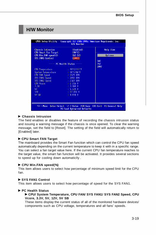
Chassis IntrusionThe field enables or disables the feature of recording the chassis intrusion statusand issuing a warning message if the chassis is once opened. To clear the warningmessage, set the field to [Reset]. The setting of the field will automatically return to[Enabled] later.
CPU Smart FAN TargetThe mainboard provides the Smart Fan function which can control the CPU fan speedautomatically depending on the current temperature to keep it with in a specific range.You can select a fan target value here. If the current CPU fan temperature reaches tothe target value, the smart fan function will be activated. It provides several sectionsto speed up for cooling down automaticlly .
CPU Min.FAN speed(%)This item allows users to select how percentage of minimum speed limit for the CPUfan.
SYS FAN1 ControlThis item allows users to select how percentage of speed for the SYS FAN1.
PC Health Status CPU/ System Temperature, CPU FAN/ SYS FAN1/ SYS FAN2 Speed, CPU
Vcore, 3.3V, 5V, 12V, 5V SBThese items display the current status of all of the monitored hardware devices/components such as CPU voltage, temperatures and all fans’ speeds.
H/W Monitor
7345v1.0-3_BIOS.p65 2007/5/11, 下午 02:0319
3-20
MS-7345 Mainboard
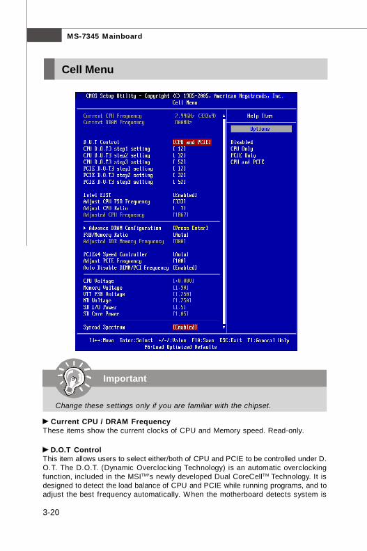
Current CPU / DRAM FrequencyThese items show the current clocks of CPU and Memory speed. Read-only.
D.O.T ControlThis item allows users to select either/both of CPU and PCIE to be controlled under D.O.T. The D.O.T. (Dynamic Overclocking Technology) is an automatic overclockingfunction, included in the MSITM’s newly developed Dual CoreCellTM Technology. It isdesigned to detect the load balance of CPU and PCIE while running programs, and toadjust the best frequency automatically. When the motherboard detects system is
Cell Menu
Important
Change these settings only if you are familiar with the chipset.
7345v1.0-3_BIOS.p65 2007/5/11, 下午 02:0320
3-21
BIOS Setup
running programs, it will speed up automatically to make the program run smoothlyand faster. When the system is temporarily suspending or staying in the low loadbalance, it will restore the default settings instead. Usually the Dynamic OverclockingTechnology will be powered only when users' PC need to run huge amount of datalike 3D games or the video process, and the CPU and PCIE frequency need to beboosted up to enhance the overall performance.
CPU D.O.T3 step1/2/3 settingDue to D.O.T can detect the CPU loading and increase the f requency with 3overclocking steps. These items allow users to select the speed up range of eachstep.
PCIE D.O.T3 step1/2/3 settingDue to D.O.T can detect the PCIE loading and increase the frequency with 3overclocking steps. These items allow users to select the speed up range of eachstep.
Intel EISTThe Enhanced Intel SpeedStep technology allows you to set the performance level ofthe microprocessor whether the computer is running on battery or AC power. Thisfield will appear after you installed the CPU which support speedstep technology.
Adjust CPU FSB FrequencyThis item allows you to set the CPU FSB frequency (in MHz).
Adjust CPU RatioThis field appears only when the CPU supports this function. It is adjustable onlywhen Intel EIST set to Disable. This item allows you to set the CPU ratio.
Adjusted CPU FrequencyIt shows the adjusted CPU frequency (FSB x Ratio). Read-only.
Advance DRAM ConfigurationPress <Enter> to enter the sub-menu and the following screen appears.
Important
Even though the Dynamic Overclocking Technology is more stable thanmanual overclocking, basically, it is still risky. We suggest user to makesure that your CPU can afford to overclocking regularly first. If you find thePC appears to be unstable or reboot incidentally, it's better to disable theDynamic Overclocking or to lower the level of overclocking options. By theway, if you need to conduct overclocking manually, you also need to disablethe Dynamic OverClocking first.
7345v1.0-3_BIOS.p65 2007/5/11, 下午 02:0321
3-22
MS-7345 Mainboard
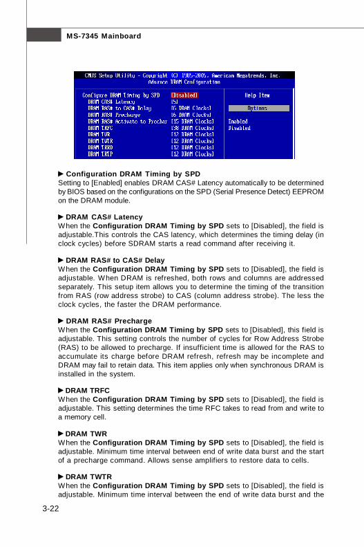
Configuration DRAM Timing by SPDSetting to [Enabled] enables DRAM CAS# Latency automatically to be determinedby BIOS based on the configurations on the SPD (Serial Presence Detect) EEPROMon the DRAM module.
DRAM CAS# LatencyWhen the Configuration DRAM Timing by SPD sets to [Disabled], the field isadjustable.This controls the CAS latency, which determines the timing delay (inclock cycles) before SDRAM starts a read command after receiving it.
DRAM RAS# to CAS# DelayWhen the Configuration DRAM Timing by SPD sets to [Disabled], the field isadjustable. When DRAM is refreshed, both rows and columns are addressedseparately. This setup item allows you to determine the timing of the transitionfrom RAS (row address strobe) to CAS (column address strobe). The less theclock cycles, the faster the DRAM performance.
DRAM RAS# PrechargeWhen the Configuration DRAM Timing by SPD sets to [Disabled], this field isadjustable. This setting controls the number of cycles for Row Address Strobe(RAS) to be allowed to precharge. If insufficient time is allowed for the RAS toaccumulate its charge before DRAM refresh, refresh may be incomplete andDRAM may fail to retain data. This item applies only when synchronous DRAM isinstalled in the system.
DRAM TRFCWhen the Configuration DRAM Timing by SPD sets to [Disabled], the field isadjustable. This setting determines the time RFC takes to read from and write toa memory cell.
DRAM TWRWhen the Configuration DRAM Timing by SPD sets to [Disabled], the field isadjustable. Minimum time interval between end of write data burst and the startof a precharge command. Allows sense amplifiers to restore data to cells.
DRAM TWTRWhen the Configuration DRAM Timing by SPD sets to [Disabled], the field isadjustable. Minimum time interval between the end of write data burst and the
7345v1.0-3_BIOS.p65 2007/5/11, 下午 02:0322
3-23
BIOS Setup
start of a column-read command. It allows I/O gating to overdrive sense amplifiersbefore read command starts.
DRAM TRRDWhen the Configuration DRAM Timing by SPD sets to [Disabled], the field isadjustable. Specifies the active-to-active delay of different banks. Time intervalbetween a read and a precharge command.
DRAM TRTPWhen the Configuration DRAM Timing by SPD sets to [Disabled], the field isadjustable. Time interval between a read and a precharge command.
FSB/Memory RatioThis item will allow you to adjust the FSB/Ratio of the memory.
Adjusted DDR Memory FrequencyIt shows the adjusted DDR Memory frequency. Read-only.
PCIEx4 Speed ControllerThis item will allow you to select the PCIEx4 speed.
Adjust PCIE FrequencyThis field allows you to select the PCIE frequency (in MHz).
Auto Disable DIMM/PCI FrequencyWhen set to [Enabled], the system will remove (turn off) clocks from empty DIMM andPCI slots to minimize the electromagnetic interference (EMI).
CPU Voltage / Momory Voltage / VTT FSB Voltage / NB Voltage / SB I/OPower / SB Core PowerThese items dispaly the power status of CPU, Memory, FSB and chipset. Read-only.
Spread SpectrumWhen the motherboard’s clock generator pulses, the extreme values (spikes) of thepulses create EMI (Electromagnetic Interference). The Spread Spectrum functionreduces the EMI generated by modulating the pulses so that the spikes of the pulsesare reduced to flatter curves. If you do not have any EMI problem, leave the setting atDisabled for optimal system stability and performance. But if you are plagued by EMI,set to Enabled for EMI reduction. Remember to disable Spread Spectrum if you areoverclocking because even a slight jitter can introduce a temporary boost in clockspeed which may just cause your overclocked processor to lock up.
7345v1.0-3_BIOS.p65 2007/5/11, 下午 02:0323
3-24
MS-7345 Mainboard
1. If you do not have any EMI problem, leave the setting at [Disabled] foroptimal system stability and performance. But if you are plagued by EMI,select the value of Spread Spectrum for EMI reduction.
2. The greater the Spread Spectrum value is, the greater the EMI is reduced,and the system will become less stable. For the most suitable SpreadSpectrum value, please consult your local EMI regulation.
3. Remember to disable Spread Spectrum if you are overclocking becauseeven a slight jitter can introduce a temporary boost in clock speed whichmay just cause your overclocked processor to lock up.
Important
7345v1.0-3_BIOS.p65 2007/5/11, 下午 02:0324

3-25
BIOS Setup
CPU and Memory Clock OverclockingThe D.O.T Control, Adjust CPU FSB Frequency, Adjust CPU Ratio, FSB/MemoryRatio are the items for you to overclock the CPU and the Memory. Please refer to thedescriptions of these fields for more information.
2. At the fourth reboot, BIOS will determine that the previous overclocking is failedand restore the default settings automatically. Please press any key to boot thesystem normally when the following message appears on screen.
Warning !!! The previous performance of overclocking is failed,and the system is restored to the defaults setting,Press any key exclude "DEL" to enter SETUP.......
Clear CMOS- Please refer to “chapter 2” for more information about how to clear CMOS data.
Two ways to save your system from failed overclocking... Reboot
1. Press the Power button to reboot the system three times. Please note that, toavoid electric current to affect other devices or components, we suggest aninterval of more than 10 seconds among the reboot actions.
1. CPU Speed = CPU Frequency * CPU Ratio2. This motherboard supports overclocking greatly. However, please make
sure your peripherals and components are bearable for some specialsett ings. Any operation that exceeds product specif ication is notrecommended. Any risk or damge resulting from improper operation willnot be under our product warranty.
Important
7345v1.0-3_BIOS.p65 2007/5/11, 下午 02:0325
3-26
MS-7345 Mainboard
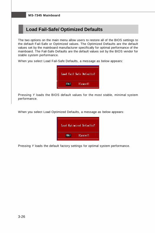
The two options on the main menu allow users to restore all of the BIOS settings tothe default Fail-Safe or Optimized values. The Optimized Defaults are the defaultvalues set by the mainboard manufacturer specifically for optimal performance of themainboard. The Fail-Safe Defaults are the default values set by the BIOS vendor forstable system performance.
When you select Load Fail-Safe Defaults, a message as below appears:
Pressing Y loads the BIOS default values for the most stable, minimal systemperformance.
When you select Load Optimized Defaults, a message as below appears:
Pressing Y loads the default factory settings for optimal system performance.
Load Fail-Safe/ Optimized Defaults
7345v1.0-3_BIOS.p65 2007/5/11, 下午 02:0326
3-27
BIOS Setup
BIOS Setting Password
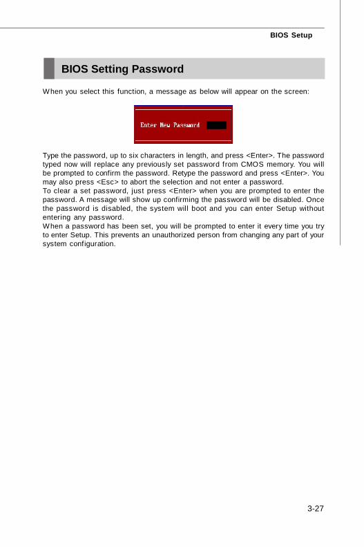
When you select this function, a message as below will appear on the screen:
Type the password, up to six characters in length, and press <Enter>. The passwordtyped now will replace any previously set password from CMOS memory. You willbe prompted to confirm the password. Retype the password and press <Enter>. Youmay also press <Esc> to abort the selection and not enter a password.To clear a set password, just press <Enter> when you are prompted to enter thepassword. A message will show up confirming the password will be disabled. Oncethe password is disabled, the system will boot and you can enter Setup withoutentering any password.When a password has been set, you will be prompted to enter it every time you tryto enter Setup. This prevents an unauthorized person from changing any part of yoursystem configuration.
7345v1.0-3_BIOS.p65 2007/5/11, 下午 02:0327

A-1
Realtek ALC888/888T Audio
Realtek ALC888/888T AudioAppendix A
The Realtek ALC888/888T provides 10-channel DACthat simultaneously supports 7.1 sound playback and 2channels of independent stereo sound output (multiplestreaming) through the Front-Out-Left and Front-Out-Right channels.
7345v1.0-A_Realtek ALC888-888T.p65 2007/5/11, 下午 02:031
MS-7345 Mainboard
A-2a
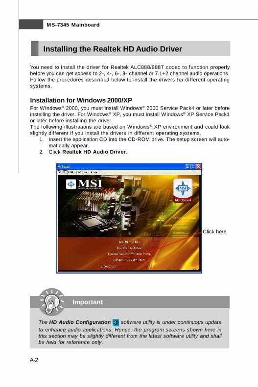
You need to install the driver for Realtek ALC888/888T codec to function properlybefore you can get access to 2-, 4-, 6-, 8- channel or 7.1+2 channel audio operations.Follow the procedures described below to install the drivers for different operatingsystems.
Installation for Windows 2000/XPFor Windows® 2000, you must install Windows® 2000 Service Pack4 or later beforeinstalling the driver. For Windows® XP, you must install Windows® XP Service Pack1or later before installing the driver.The following illustrations are based on Windows® XP environment and could lookslightly different if you install the drivers in different operating systems.
1. Insert the application CD into the CD-ROM drive. The setup screen will auto-matically appear.
2. Click Realtek HD Audio Driver.
Installing the Realtek HD Audio Driver
Important
The HD Audio Configuration software utility is under continuous updateto enhance audio applications. Hence, the program screens shown here inthis section may be slightly different from the latest software utility and shallbe held for reference only.
Click here
7345v1.0-A_Realtek ALC888-888T.p65 2007/5/11, 下午 02:032
A-3
Realtek ALC888/888T Audio
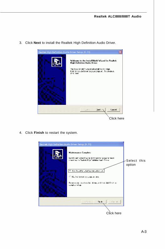
3. Click Next to install the Realtek High Definition Audio Driver.
Click here
Select thisoption
4. Click Finish to restart the system.
Click here
7345v1.0-A_Realtek ALC888-888T.p65 2007/5/11, 下午 02:033
MS-7345 Mainboard
A-4a
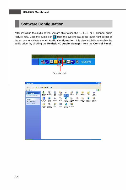
After installing the audio driver, you are able to use the 2-, 4-, 6- or 8- channel audiofeature now. Click the audio icon from the system tray at the lower-right corner ofthe screen to activate the HD Audio Configuration. It is also available to enable theaudio driver by clicking the Realtek HD Audio Manager from the Control Panel.
Double click
Software Configuration
7345v1.0-A_Realtek ALC888-888T.p65 2007/5/11, 下午 02:034
A-5
Realtek ALC888/888T Audio
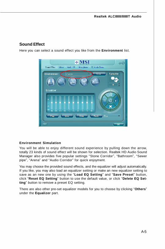
Sound Effect
Environment SimulationYou will be able to enjoy different sound experience by pulling down the arrow,totally 23 kinds of sound effect will be shown for selection. Realtek HD Audio SoundManager also provides five popular settings “Stone Corridor”, “Bathroom”, “Sewerpipe”, “Arena” and “Audio Corridor” for quick enjoyment.
You may choose the provided sound effects, and the equalizer will adjust automatically.If you like, you may also load an equalizer setting or make an new equalizer setting tosave as an new one by using the “Load EQ Setting” and “Save Preset” button,click “Reset EQ Setting” button to use the default value, or click “Delete EQ Set-ting” button to remove a preset EQ setting.
There are also other pre-set equalizer models for you to choose by clicking “Others”under the Equalizer part.
Here you can select a sound effect you like from the Environment list.
7345v1.0-A_Realtek ALC888-888T.p65 2007/5/11, 下午 02:035
MS-7345 Mainboard
A-6a
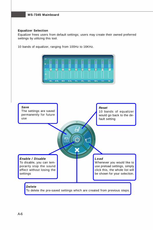
SaveThe settings are savedpermanently for futureuse
Reset10 bands of equalizerwould go back to the de-fault setting
Enable / DisableTo disable, you can tem-porarily s top the soundeffect without losing thesettings
LoadWhenever you would like touse preload settings, simplyclick this, the whole list willbe shown for your selection.
DeleteTo delete the pre-saved settings which are created from previous steps.
Equalizer SelectionEqualizer frees users from default settings; users may create their owned preferredsettings by utilizing this tool.
10 bands of equalizer, ranging from 100Hz to 16KHz.
7345v1.0-A_Realtek ALC888-888T.p65 2007/5/11, 下午 02:036

A-7
Realtek ALC888/888T Audio
Raise the key
Lower the key
Remove thehuman voice
Frequently Used Equalizer SettingRealtek recognizes the needs that you might have. By leveraging our long experienceat audio field, Realtek HD Audio Sound Manager provides you certain optimized equal-izer settings that are frequently used for your quick enjoyment.
[How to Use It]Other than the buttons “Pop” “Live” “Club” & “Rock” shown on the page, to pull downthe arrow in “Others”, you will find more optimized settings available to you.
Karaoke ModeKaraoke mode brings Karaoke fun back home. Simply using the music you usuallyplay, Karaoke mode can help you eliminate the vocal of the song or adjust the key toaccommodate your range.1.Vocal Cancellation: Single click on “Voice Cancellation”, the vocal of the song would be eliminated, while the background music is still in place, and you can be that singer!2.Key Adjustment: Using “Up / Down Arrow” to find a key which better fits your vocal range.
7345v1.0-A_Realtek ALC888-888T.p65 2007/5/11, 下午 02:037
MS-7345 Mainboard
A-8a
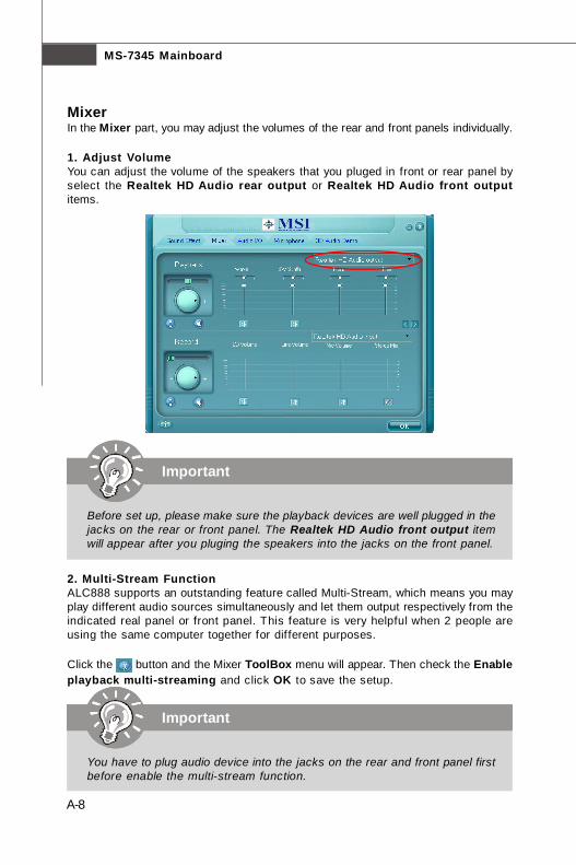
MixerIn the Mixer part, you may adjust the volumes of the rear and front panels individually.
1. Adjust VolumeYou can adjust the volume of the speakers that you pluged in front or rear panel byselect the Realtek HD Audio rear output or Realtek HD Audio front outputitems.
2. Multi-Stream FunctionALC888 supports an outstanding feature called Multi-Stream, which means you mayplay different audio sources simultaneously and let them output respectively from theindicated real panel or front panel. This feature is very helpful when 2 people areusing the same computer together for different purposes.
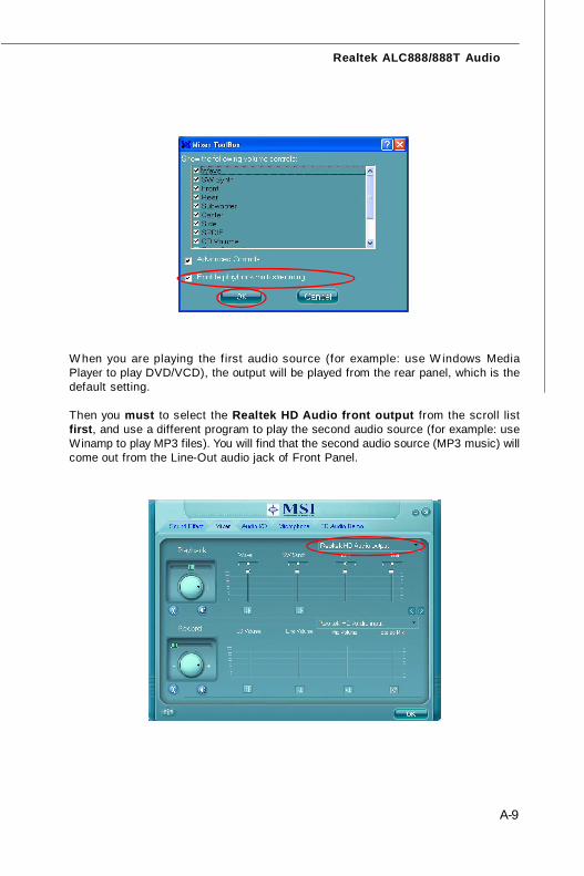
Click the button and the Mixer ToolBox menu will appear. Then check the Enableplayback multi-streaming and click OK to save the setup.
Important
Before set up, please make sure the playback devices are well plugged in thejacks on the rear or front panel. The Realtek HD Audio front output itemwill appear after you pluging the speakers into the jacks on the front panel.
Important
You have to plug audio device into the jacks on the rear and front panel firstbefore enable the multi-stream function.
7345v1.0-A_Realtek ALC888-888T.p65 2007/5/11, 下午 02:038
A-9
Realtek ALC888/888T Audio
W hen you are playing the f irst audio source (for example: use W indows MediaPlayer to play DVD/VCD), the output will be played from the rear panel, which is thedefault setting.
Then you must to select the Realtek HD Audio front output from the scroll listfirst, and use a different program to play the second audio source (for example: useWinamp to play MP3 files). You will find that the second audio source (MP3 music) willcome out from the Line-Out audio jack of Front Panel.
7345v1.0-A_Realtek ALC888-888T.p65 2007/5/11, 下午 02:039
MS-7345 Mainboard
A-10a
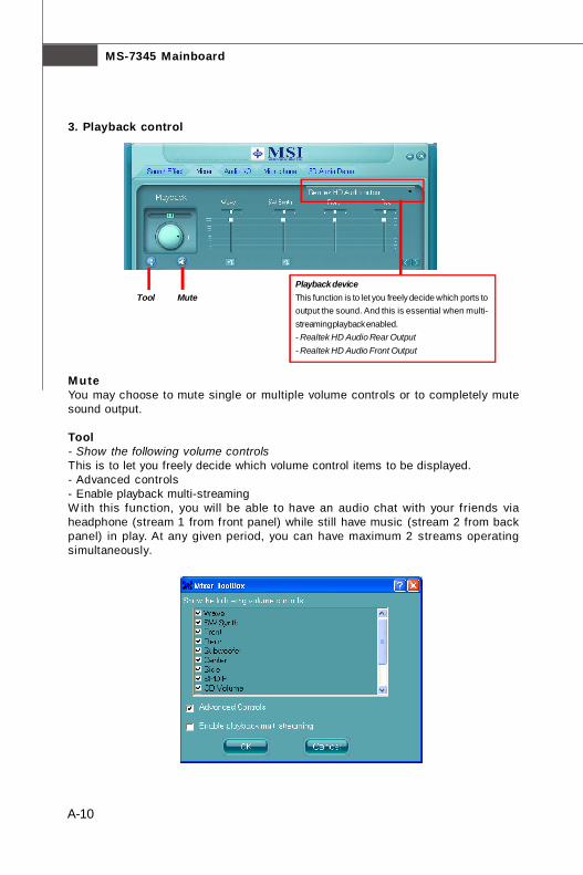
3. Playback control
Playback deviceThis function is to let you freely decide which ports tooutput the sound. And this is essential when multi-streaming playback enabled.- Realtek HD Audio Rear Output- Realtek HD Audio Front Output
Tool Mute
MuteYou may choose to mute single or multiple volume controls or to completely mutesound output.
Tool- Show the following volume controlsThis is to let you freely decide which volume control items to be displayed.- Advanced controls- Enable playback multi-streamingW ith this function, you will be able to have an audio chat with your friends viaheadphone (stream 1 from front panel) while still have music (stream 2 from backpanel) in play. At any given period, you can have maximum 2 streams operatingsimultaneously.
7345v1.0-A_Realtek ALC888-888T.p65 2007/5/11, 下午 02:0310
A-11
Realtek ALC888/888T Audio
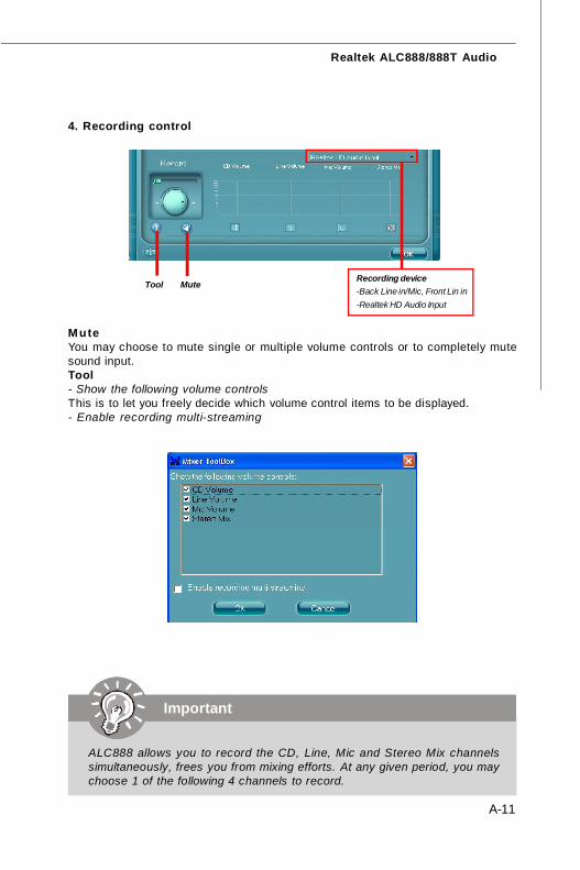
4. Recording control
Recording device-Back Line in/Mic, Front Lin in-Realtek HD Audio Input
MuteYou may choose to mute single or multiple volume controls or to completely mutesound input.Tool- Show the following volume controlsThis is to let you freely decide which volume control items to be displayed.- Enable recording multi-streaming
Tool Mute
Important
ALC888 allows you to record the CD, Line, Mic and Stereo Mix channelssimultaneously, frees you from mixing efforts. At any given period, you maychoose 1 of the following 4 channels to record.
7345v1.0-A_Realtek ALC888-888T.p65 2007/5/11, 下午 02:0311
MS-7345 Mainboard
A-12a
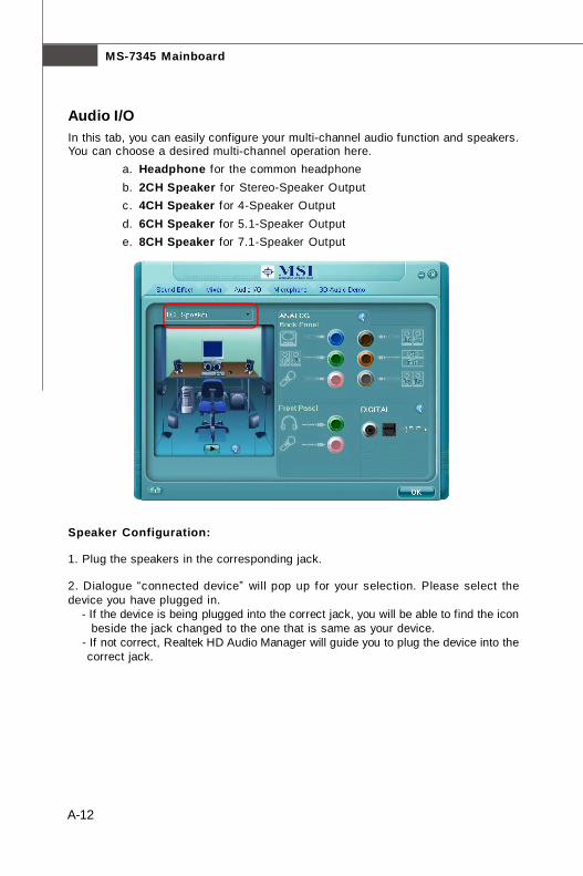
Audio I/OIn this tab, you can easily configure your multi-channel audio function and speakers.You can choose a desired multi-channel operation here.
a. Headphone for the common headphoneb. 2CH Speaker for Stereo-Speaker Outputc. 4CH Speaker for 4-Speaker Outputd. 6CH Speaker for 5.1-Speaker Outpute. 8CH Speaker for 7.1-Speaker Output
Speaker Configuration:
1. Plug the speakers in the corresponding jack.
2. Dialogue “connected device” will pop up for your selection. Please select thedevice you have plugged in. - If the device is being plugged into the correct jack, you will be able to find the icon beside the jack changed to the one that is same as your device. - If not correct, Realtek HD Audio Manager will guide you to plug the device into the correct jack.
7345v1.0-A_Realtek ALC888-888T.p65 2007/5/11, 下午 02:0312
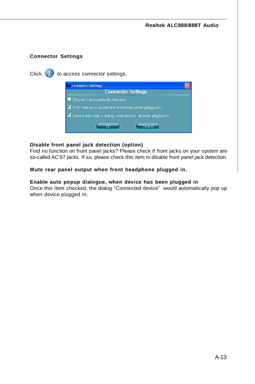
A-13
Realtek ALC888/888T Audio
Connector Settings
Click to access connector settings.
Disable front panel jack detection (option)Find no function on front panel jacks? Please check if front jacks on your system areso-called AC’97 jacks. If so, please check this item to disable front panel jack detection.
Mute rear panel output when front headphone plugged in.
Enable auto popup dialogue, when device has been plugged inOnce this item checked, the dialog “Connected device” would automatically pop upwhen device plugged in.
7345v1.0-A_Realtek ALC888-888T.p65 2007/5/11, 下午 02:0313
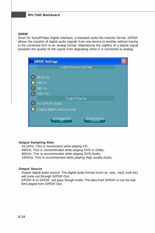
MS-7345 Mainboard
A-14a
S/PDIFShort for Sony/Philips Digital Interface, a standard audio file transfer format. S/PDIFallows the transfer of digital audio signals from one device to another without havingto be converted first to an analog format. Maintaining the viability of a digital signalprevents the quality of the signal from degrading when it is converted to analog.
Output Sampling Rate 44.1KHz: This is recommend while playing CD. 48KHz: This is recommended while playing DVD or Dolby. 96KHz: This is recommended while playing DVD-Audio. 192KHz: This is recommended while playing High quality Audio.
Output Source Output digital audio source: The digital audio format (such as .wav, .mp3,.midi etc) will come out through S/PDIF-Out. S/PDIF-in to S/PDIF -out pass though mode: The data from S/PDIF-In can be real- time played from S/PDIF-Out.
7345v1.0-A_Realtek ALC888-888T.p65 2007/5/11, 下午 02:0314
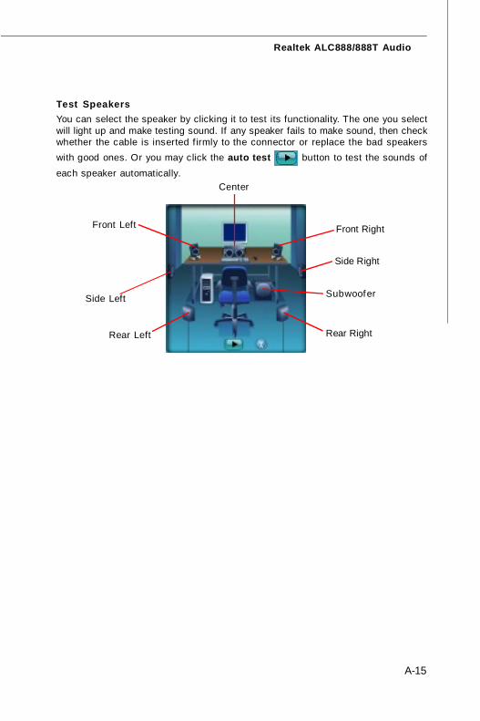
A-15
Realtek ALC888/888T Audio
Test SpeakersYou can select the speaker by clicking it to test its functionality. The one you selectwill light up and make testing sound. If any speaker fails to make sound, then checkwhether the cable is inserted f irmly to the connector or replace the bad speakerswith good ones. Or you may click the auto test button to test the sounds ofeach speaker automatically.
Subwoofer
Front Right
Rear Right
Center
Front Left
Rear Left
Side Left
Side Right
7345v1.0-A_Realtek ALC888-888T.p65 2007/5/11, 下午 02:0315
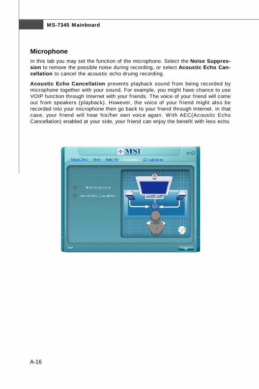
MS-7345 Mainboard
A-16a
MicrophoneIn this tab you may set the function of the microphone. Select the Noise Suppres-sion to remove the possible noise during recording, or select Acoustic Echo Can-cellation to cancel the acoustic echo druing recording.
Acoustic Echo Cancellation prevents playback sound from being recorded bymicrophone together with your sound. For example, you might have chance to useVOIP function through Internet with your friends. The voice of your friend will comeout from speakers (playback). However, the voice of your friend might also berecorded into your microphone then go back to your friend through Internet. In thatcase, your friend will hear his /her own voice again. W ith AEC(Acoustic EchoCancellation) enabled at your side, your friend can enjoy the benefit with less echo.
7345v1.0-A_Realtek ALC888-888T.p65 2007/5/11, 下午 02:0316
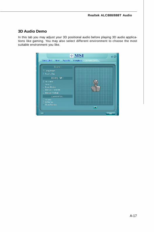
A-17
Realtek ALC888/888T Audio
3D Audio DemoIn this tab you may adjust your 3D positional audio before playing 3D audio applica-tions like gaming. You may also select different environment to choose the mostsuitable environment you like.
7345v1.0-A_Realtek ALC888-888T.p65 2007/5/11, 下午 02:0317
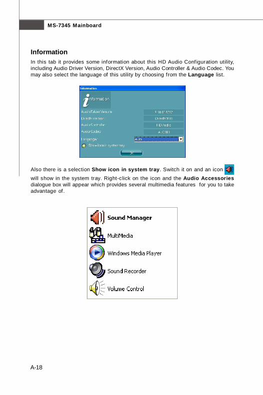
MS-7345 Mainboard
A-18a
InformationIn this tab it provides some information about this HD Audio Configuration utility,including Audio Driver Version, DirectX Version, Audio Controller & Audio Codec. Youmay also select the language of this utility by choosing from the Language list.
Also there is a selection Show icon in system tray. Switch it on and an icon
will show in the system tray. Right-click on the icon and the Audio Accessoriesdialogue box will appear which provides several multimedia features for you to takeadvantage of.
7345v1.0-A_Realtek ALC888-888T.p65 2007/5/11, 下午 02:0318
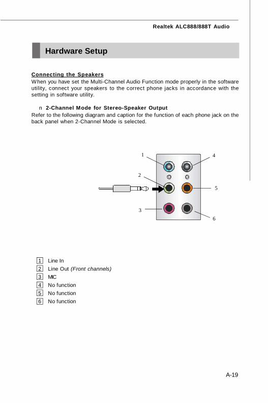
A-19
Realtek ALC888/888T Audio
Connecting the SpeakersWhen you have set the Multi-Channel Audio Function mode properly in the softwareutility, connect your speakers to the correct phone jacks in accordance with thesetting in software utility.
n 2-Channel Mode for Stereo-Speaker OutputRefer to the following diagram and caption for the function of each phone jack on theback panel when 2-Channel Mode is selected.
1 Line In2 Line Out (Front channels)3 MIC4 No function5 No function6 No function
Hardware Setup
3
1
2
6
4
5
7345v1.0-A_Realtek ALC888-888T.p65 2007/5/11, 下午 02:0319
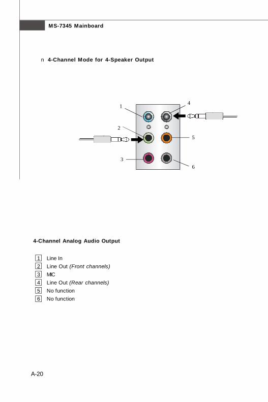
MS-7345 Mainboard
A-20a
n 4-Channel Mode for 4-Speaker Output
4-Channel Analog Audio Output
1 Line In2 Line Out (Front channels)3 MIC4 Line Out (Rear channels)5 No function6 No function
3
1
2
6
4
5
7345v1.0-A_Realtek ALC888-888T.p65 2007/5/11, 下午 02:0320
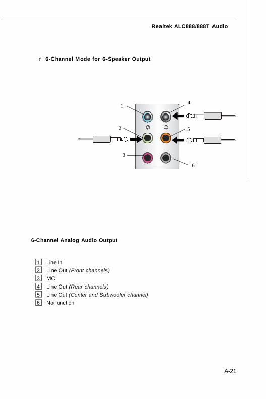
A-21
Realtek ALC888/888T Audio
n 6-Channel Mode for 6-Speaker Output
6-Channel Analog Audio Output
1 Line In2 Line Out (Front channels)3 MIC4 Line Out (Rear channels)5 Line Out (Center and Subwoofer channel)6 No function
1
2
6
4
5
3
7345v1.0-A_Realtek ALC888-888T.p65 2007/5/11, 下午 02:0321
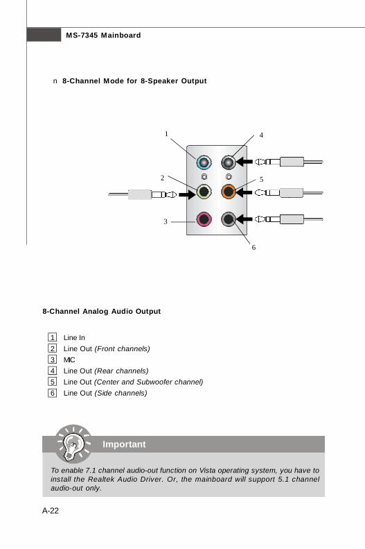
MS-7345 Mainboard
A-22a
n 8-Channel Mode for 8-Speaker Output
8-Channel Analog Audio Output
1 Line In2 Line Out (Front channels)3 MIC4 Line Out (Rear channels)5 Line Out (Center and Subwoofer channel)6 Line Out (Side channels)
1
2
6
4
5
3
Important
To enable 7.1 channel audio-out function on Vista operating system, you have toinstall the Realtek Audio Driver. Or, the mainboard will support 5.1 channelaudio-out only.
7345v1.0-A_Realtek ALC888-888T.p65 2007/5/11, 下午 02:0322
B-1
Dual Core Center
Dual Core Center
Dual CoreCenter, the most useful and powerful utilitythat MSI has spent much research and ef forts todevelop, helps users to monitor or configure the hard-ware status of MSI Mainboard & MSI Graphics card inwindows, such as CPU/GPU clock, voltage, fan speedand temperature.Before you install the Dual CoreCenter, please makesure the system has meet the following requirements:
1. Intel Pentium4 / Celeron, AMD Athlon XP/ Sempron or compatible CPU with PCI Express slot.2. 256MB system memory.3. CD-ROM drive for software installation.4. Operation system: Windows XP.5. DotNet Frame Work 2.0
Appendix B
7345v1.0-B_dual core center.p65 2007/5/11, 下午 02:031
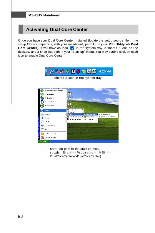
B-2
MS-7345 Mainboard
Activating Dual Core Center
Once you have your Dual Core Center installed (locate the setup source file in thesetup CD accompanying with your mainboard, path: Utility --> MSI Utility --> DualCore Center), it will have an icon in the system tray, a short cut icon on thedesktop, and a short cut path in your “Start-up” menu. You may double-click on eachicon to enable Dual Core Center.
short-cut icon in the system tray
short-cut path in the start-up menu( p ath : S t ar t - - > P r og rams - - > MSI - - >DualCoreCenter-->DualCoreCenter)
7345v1.0-B_dual core center.p65 2007/5/11, 下午 02:032
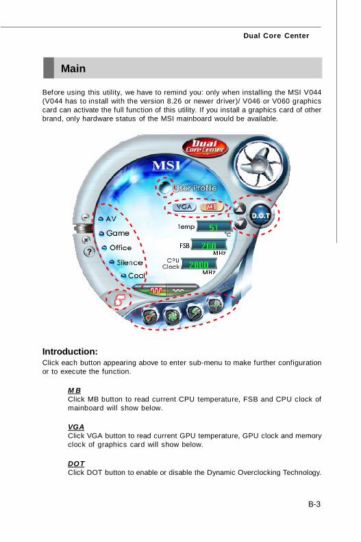
B-3
Dual Core Center
Main
Before using this utility, we have to remind you: only when installing the MSI V044(V044 has to install with the version 8.26 or newer driver)/ V046 or V060 graphicscard can activate the full function of this utility. If you install a graphics card of otherbrand, only hardware status of the MSI mainboard would be available.
Introduction:Click each button appearing above to enter sub-menu to make further configurationor to execute the function.
M BClick MB button to read current CPU temperature, FSB and CPU clock ofmainboard will show below.
VGAClick VGA button to read current GPU temperature, GPU clock and memoryclock of graphics card will show below.
DOTClick DOT button to enable or disable the Dynamic Overclocking Technology.
7345v1.0-B_dual core center.p65 2007/5/11, 下午 02:033
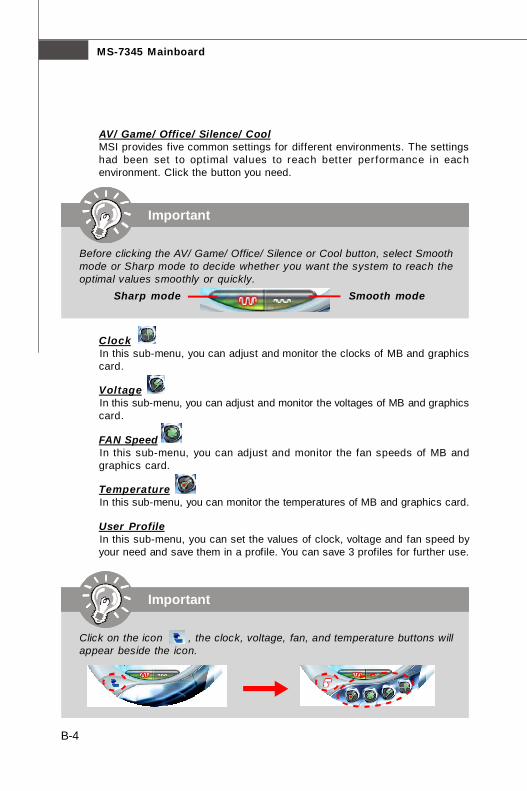
B-4
MS-7345 Mainboard
AV/ Game/ Office/ Silence/ CoolMSI provides five common settings for different environments. The settingshad been set to optimal values to reach better performance in eachenvironment. Click the button you need.
ClockIn this sub-menu, you can adjust and monitor the clocks of MB and graphicscard.
VoltageIn this sub-menu, you can adjust and monitor the voltages of MB and graphicscard.
FAN SpeedIn this sub-menu, you can adjust and monitor the fan speeds of MB andgraphics card.
TemperatureIn this sub-menu, you can monitor the temperatures of MB and graphics card.
User ProfileIn this sub-menu, you can set the values of clock, voltage and fan speed byyour need and save them in a profile. You can save 3 profiles for further use.
Important
Click on the icon , the clock, voltage, fan, and temperature buttons willappear beside the icon.
Important
Before clicking the AV/ Game/ Office/ Silence or Cool button, select Smoothmode or Sharp mode to decide whether you want the system to reach theoptimal values smoothly or quickly.
Sharp mode Smooth mode
7345v1.0-B_dual core center.p65 2007/5/11, 下午 02:034
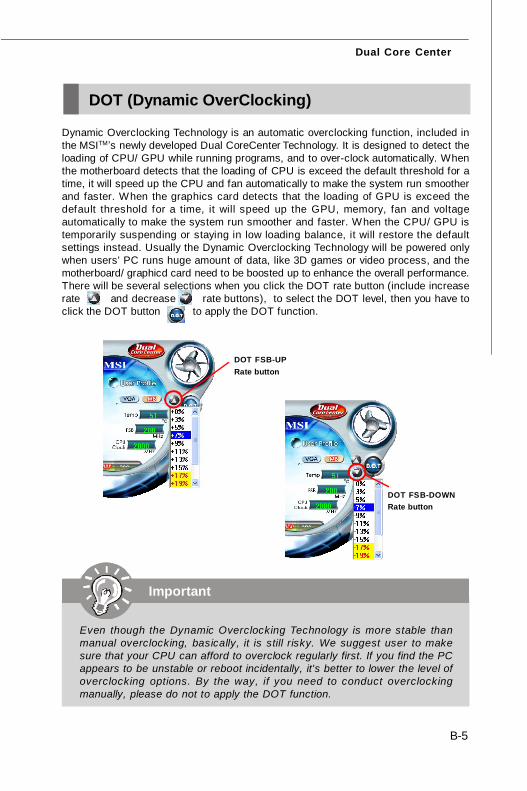
B-5
Dual Core Center
DOT (Dynamic OverClocking)
Dynamic Overclocking Technology is an automatic overclocking function, included inthe MSITM’s newly developed Dual CoreCenter Technology. It is designed to detect theloading of CPU/ GPU while running programs, and to over-clock automatically. Whenthe motherboard detects that the loading of CPU is exceed the default threshold for atime, it will speed up the CPU and fan automatically to make the system run smootherand faster. When the graphics card detects that the loading of GPU is exceed thedefault threshold for a time, it will speed up the GPU, memory, fan and voltageautomatically to make the system run smoother and faster. When the CPU/ GPU istemporarily suspending or staying in low loading balance, it will restore the defaultsettings instead. Usually the Dynamic Overclocking Technology will be powered onlywhen users' PC runs huge amount of data, like 3D games or video process, and themotherboard/ graphicd card need to be boosted up to enhance the overall performance.There will be several selections when you click the DOT rate button (include increaserate and decrease rate buttons), to select the DOT level, then you have toclick the DOT button to apply the DOT function.
Important
Even though the Dynamic Overclocking Technology is more stable thanmanual overclocking, basically, it is still risky. We suggest user to makesure that your CPU can afford to overclock regularly first. If you find the PCappears to be unstable or reboot incidentally, it's better to lower the level ofoverclocking options. By the way, if you need to conduct overclockingmanually, please do not to apply the DOT function.
DOT FSB-DOWNRate button
DOT FSB-UPRate button
7345v1.0-B_dual core center.p65 2007/5/11, 下午 02:035
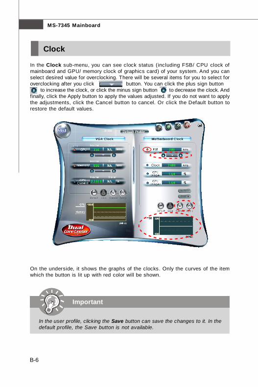
B-6
MS-7345 Mainboard
Clock
In the Clock sub-menu, you can see clock status (including FSB/ CPU clock ofmainboard and GPU/ memory clock of graphics card) of your system. And you canselect desired value for overclocking. There will be several items for you to select foroverclocking after you click button. You can click the plus sign button to increase the clock, or click the minus sign button to decrease the clock. Andfinally, click the Apply button to apply the values adjusted. If you do not want to applythe adjustments, click the Cancel button to cancel. Or click the Default button torestore the default values.
On the underside, it shows the graphs of the clocks. Only the curves of the itemwhich the button is lit up with red color will be shown.
Important
In the user profile, clicking the Save button can save the changes to it. In thedefault profile, the Save button is not available.
7345v1.0-B_dual core center.p65 2007/5/11, 下午 02:036
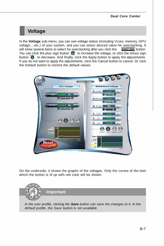
B-7
Dual Core Center
Voltage
In the Voltage sub-menu, you can see voltage status (including Vcore, memory, GPUvoltage... etc.) of your system, and you can select desired value for overclocking. Itwill show several items to select for overclocking after you click the button.You can click the plus sign button to increase the voltage, or click the minus signbutton to decrease. And finally, click the Apply button to apply the adjustments.If you do not want to apply the adjustments, click the Cancel button to cancel. Or clickthe Default button to restore the default values.
On the underside, it shows the graphs of the voltages. Only the curves of the itemwhich the button is lit up with red color will be shown.
I
Important
In the user profile, clicking the Save button can save the changes to it. In thedefault profile, the Save button is not available.
7345v1.0-B_dual core center.p65 2007/5/11, 下午 02:037
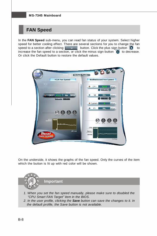
B-8
MS-7345 Mainboard
FAN Speed
In the FAN Speed sub-menu, you can read fan status of your system. Select higherspeed for better cooling effect. There are several sections for you to change the fanspeed to a section after clicking button. Click the plus sign button toincrease the fan speed to a section, or click the minus sign button to decrease.Or click the Default button to restore the default values.
On the underside, it shows the graphs of the fan speed. Only the curves of the itemwhich the button is lit up with red color will be shown.
Important
1. When you set the fan speed manually, please make sure to disabled the “CPU Smart FAN Target” item in the BIOS.2. In the user profile, clicking the Save button can save the changes to it. In the default profile, the Save button is not available.
7345v1.0-B_dual core center.p65 2007/5/11, 下午 02:038
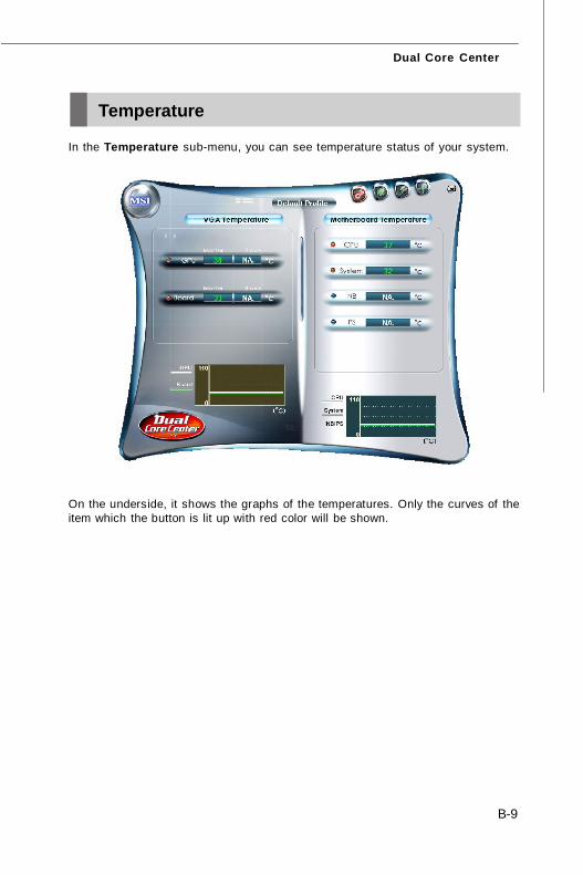
B-9
Dual Core Center
Temperature
In the Temperature sub-menu, you can see temperature status of your system.
On the underside, it shows the graphs of the temperatures. Only the curves of theitem which the button is lit up with red color will be shown.
7345v1.0-B_dual core center.p65 2007/5/11, 下午 02:039
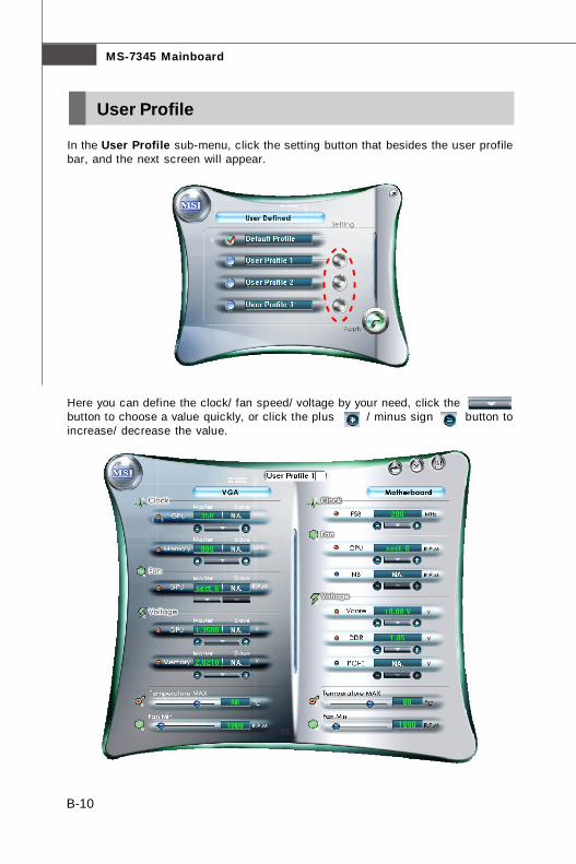
B-10
MS-7345 Mainboard
User Profile
In the User Profile sub-menu, click the setting button that besides the user profilebar, and the next screen will appear.
Here you can define the clock/ fan speed/ voltage by your need, click thebutton to choose a value quickly, or click the plus / minus sign button toincrease/ decrease the value.
7345v1.0-B_dual core center.p65 2007/5/11, 下午 02:0310
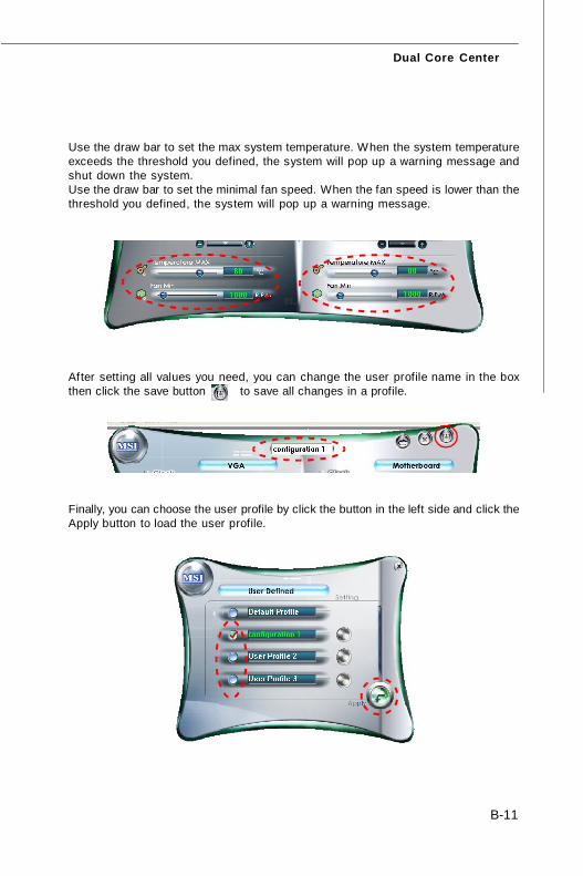
B-11
Dual Core Center
Use the draw bar to set the max system temperature. When the system temperatureexceeds the threshold you defined, the system will pop up a warning message andshut down the system.Use the draw bar to set the minimal fan speed. When the fan speed is lower than thethreshold you defined, the system will pop up a warning message.
Finally, you can choose the user profile by click the button in the left side and click theApply button to load the user profile.
After setting all values you need, you can change the user profile name in the boxthen click the save button to save all changes in a profile.
7345v1.0-B_dual core center.p65 2007/5/11, 下午 02:0311
C-1
Intel ICH9R SATA RAID
Intel ICH9R SATA RAIDAppendix C
This appendix will assist users in configuring and en-abling RAID functionality on platformsThe ICH9R RAID solution supports RAID level 0(striping), RAID level 1 (mirroring), RAID level 5 (stripingwith parity) and RAID level 10 (striping and mirroring).
7345v1.0-C_ICH9R RAID.p65 2007/5/11, 下午 02:031

MS-7345 Mainboard
C-2
ICH9R Introduction
Important
The least number of hard drives for RAID 0, RAID 1 or Matrix mode is 2. Theleast number of hard drives for RAID 10 mode is 4. And the least number ofhard drives for RAID 5 mode is 3.All the information/ volumes/ pictures listed in your system might differ fromthe illustrations in this appendix.
The ICH9R provides a hybrid solution that combines 6 independent SATAII ports forsupport of up to 6 Serial ATAII (Serial ATAII RAID) drives.
Serial ATAII (SATAII) is the latest generation of the ATA interface. SATA hard drivesdeliver blistering transfer speeds up to 300MB/sec. Serial ATA uses long, thin cables,making it easier to connect your drive and improving the airflow inside your PC. Themost outstanding features are:
1. Supports 300MB/s transfers with CRC error checking.2. Supports Hot-plug-n-play feature.3. Data handling optimizations including tagged command queuing, elevator
seek and packet chain command.
Intel® ICH9R offers RAID level 0 (Striping), RAID level 1 (Mirroring and Duplexing),RAID level 5 (Block Interleaved Distributed Parity), RAID level 10 (A Stripe of Mirrors)and Intel® Martix Storage Technology.
RAID 0 breaks the data into blocks which are written to separate hard drives. Spreadingthe hard drive I/O load across independent channels greatly improves I/O performance.RAID 1 provides data redundancy by mirroring data between the hard drives andprovides enhanced read performance. RAID 5 Provides data striping at the byte leveland also stripe error correction information. This results in excellent performanceand good fault tolerance. Level 5 is one of the most popular implementations of RAID.RAID 10 Not one of the original RAID levels, multiple RAID 1 mirrors are created, anda RAID 0 stripe is created over these. Intel Matrix RAID Technology is the advancedability for two RAID volumes to share the combined space of two hard drives beingused in unison.
7345v1.0-C_ICH9R RAID.p65 2007/5/11, 下午 02:032
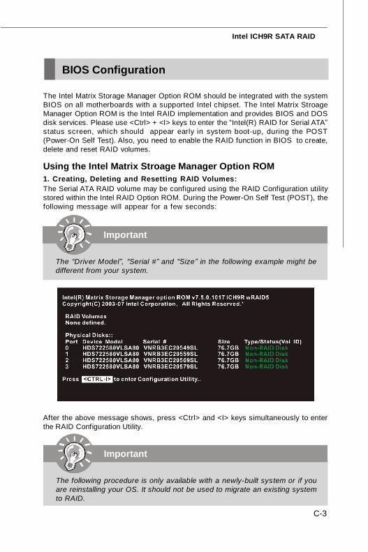
C-3
Intel ICH9R SATA RAID
BIOS Configuration
After the above message shows, press <Ctrl> and <I> keys simultaneously to enterthe RAID Configuration Utility.
Important
The “Driver Model”, “Serial #” and “Size” in the following example might bedifferent from your system.
Important
The following procedure is only available with a newly-built system or if youare reinstalling your OS. It should not be used to migrate an existing systemto RAID.
The Intel Matrix Storage Manager Option ROM should be integrated with the systemBIOS on all motherboards with a supported Intel chipset. The Intel Matrix StroageManager Option ROM is the Intel RAID implementation and provides BIOS and DOSdisk services. Please use <Ctrl> + <I> keys to enter the “Intel(R) RAID for Serial ATA”status screen, which should appear early in system boot-up, during the POST(Power-On Self Test). Also, you need to enable the RAID function in BIOS to create,delete and reset RAID volumes.
Using the Intel Matrix Stroage Manager Option ROM1. Creating, Deleting and Resetting RAID Volumes:The Serial ATA RAID volume may be configured using the RAID Configuration utilitystored within the Intel RAID Option ROM. During the Power-On Self Test (POST), thefollowing message will appear for a few seconds:
7345v1.0-C_ICH9R RAID.p65 2007/5/11, 下午 02:033
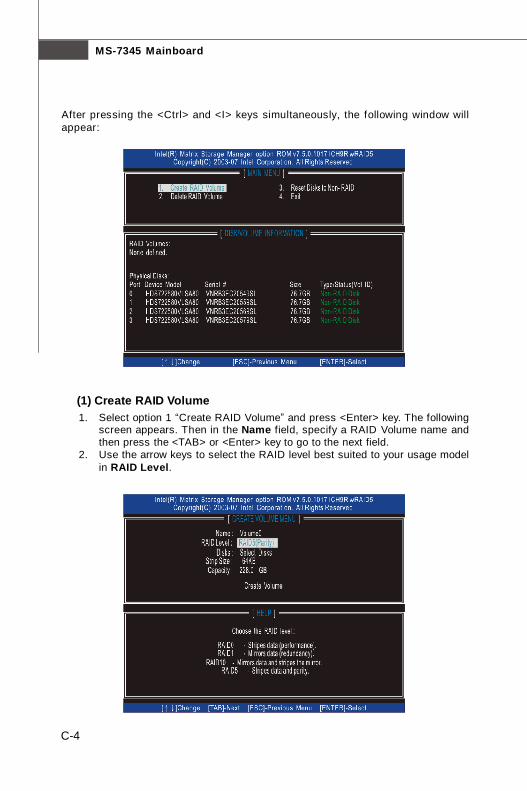
MS-7345 Mainboard
C-4
(1) Create RAID Volume1. Select option 1 “Create RAID Volume” and press <Enter> key. The following
screen appears. Then in the Name field, specify a RAID Volume name andthen press the <TAB> or <Enter> key to go to the next field.
2. Use the arrow keys to select the RAID level best suited to your usage modelin RAID Level.
After pressing the <Ctrl> and <I> keys simultaneously, the following window willappear:
7345v1.0-C_ICH9R RAID.p65 2007/5/11, 下午 02:034
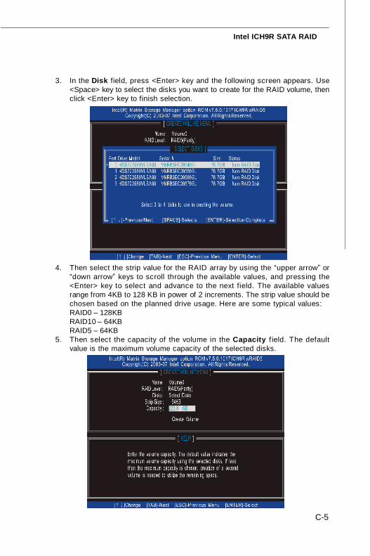
C-5
Intel ICH9R SATA RAID
3. In the Disk field, press <Enter> key and the following screen appears. Use<Space> key to select the disks you want to create for the RAID volume, thenclick <Enter> key to finish selection.
4. Then select the strip value for the RAID array by using the “upper arrow” or“down arrow” keys to scroll through the available values, and pressing the<Enter> key to select and advance to the next field. The available valuesrange from 4KB to 128 KB in power of 2 increments. The strip value should bechosen based on the planned drive usage. Here are some typical values:RAID0 – 128KBRAID10 – 64KBRAID5 – 64KB
5. Then select the capacity of the volume in the Capacity f ield. The defaultvalue is the maximum volume capacity of the selected disks.
7345v1.0-C_ICH9R RAID.p65 2007/5/11, 下午 02:035
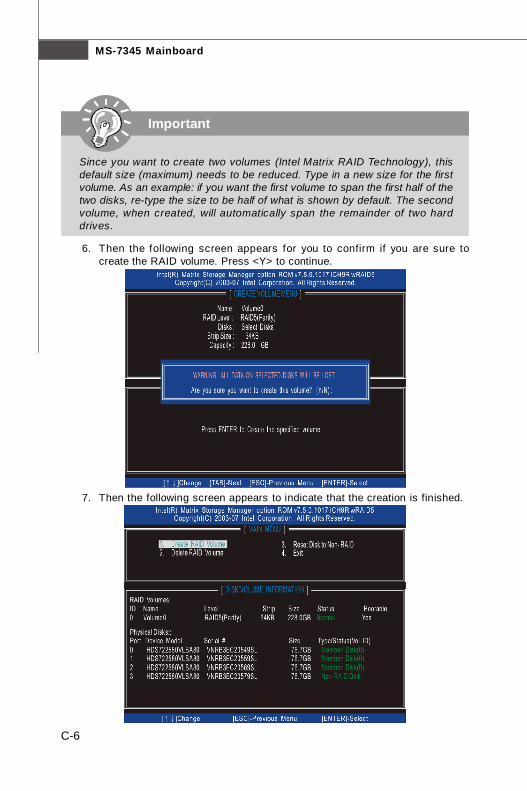
MS-7345 Mainboard
C-6
6. Then the following screen appears for you to confirm if you are sure tocreate the RAID volume. Press <Y> to continue.
7. Then the following screen appears to indicate that the creation is finished.
Important
Since you want to create two volumes (Intel Matrix RAID Technology), thisdefault size (maximum) needs to be reduced. Type in a new size for the firstvolume. As an example: if you want the first volume to span the first half of thetwo disks, re-type the size to be half of what is shown by default. The secondvolume, when created, will automatically span the remainder of two harddrives.
7345v1.0-C_ICH9R RAID.p65 2007/5/11, 下午 02:036
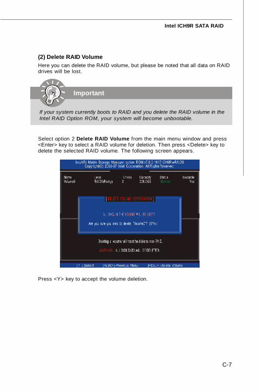
C-7
Intel ICH9R SATA RAID
(2) Delete RAID VolumeHere you can delete the RAID volume, but please be noted that all data on RAIDdrives will be lost.
Select option 2 Delete RAID Volume from the main menu window and press<Enter> key to select a RAID volume for deletion. Then press <Delete> key todelete the selected RAID volume. The following screen appears.
Press <Y> key to accept the volume deletion.
Important
If your system currently boots to RAID and you delete the RAID volume in theIntel RAID Option ROM, your system will become unbootable.
7345v1.0-C_ICH9R RAID.p65 2007/5/11, 下午 02:037
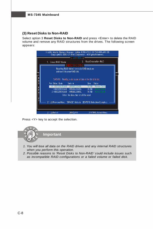
MS-7345 Mainboard
C-8
(3) Reset Disks to Non-RAIDSelect option 3 Reset Disks to Non-RAID and press <Enter> to delete the RAIDvolume and remove any RAID structures from the drives. The following screenappears:
Press <Y> key to accept the selection.
Important
1. You will lose all data on the RAID drives and any internal RAID structureswhen you perform this operation.
2. Possible reasons to ‘Reset Disks to Non-RAID’ could include issues suchas incompatible RAID configurations or a failed volume or failed disk.
7345v1.0-C_ICH9R RAID.p65 2007/5/11, 下午 02:038
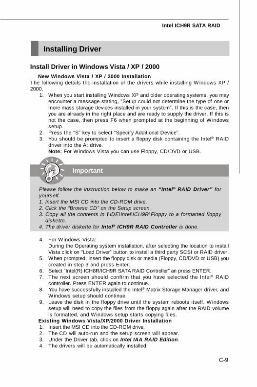
C-9
Intel ICH9R SATA RAID
Installing Driver
Install Driver in Windows Vista / XP / 2000Ü New Windows Vista / XP / 2000 InstallationThe following details the installation of the drivers while installing W indows XP /2000.
1. When you start installing Windows XP and older operating systems, you mayencounter a message stating, “Setup could not determine the type of one ormore mass storage devices installed in your system”. If this is the case, thenyou are already in the right place and are ready to supply the driver. If this isnot the case, then press F6 when prompted at the beginning of W indowssetup.
2. Press the “S” key to select “Specify Additional Device”.3. You should be prompted to insert a f loppy disk containing the Intel® RAID
driver into the A: drive.Note: For Windows Vista you can use Floppy, CD/DVD or USB.
Important
Please follow the instruction below to make an “Intel® RAID Driver” foryourself.1. Insert the MSI CD into the CD-ROM drive.2. Click the “Browse CD” on the Setup screen.3. Copy all the contents in \\IDE\Intel\ICH9R\Floppy to a formatted floppy
diskette.4. The driver diskette for Intel® ICH9R RAID Controller is done.
4. For Windows Vista:During the Operating system installation, after selecting the location to installVista click on “Load Driver” button to install a third party SCSI or RAID driver.
5. When prompted, insert the floppy disk or media (Floppy, CD/DVD or USB) youcreated in step 3 and press Enter.
6. Select “Intel(R) ICH8R/ICH9R SATA RAID Controller” an press ENTER.7. The next screen should confirm that you have selected the Intel® RAID
controller. Press ENTER again to continue.8. You have successfully installed the Intel® Matrix Storage Manager driver, and
Windows setup should continue.9. Leave the disk in the floppy drive until the system reboots itself. Windows
setup will need to copy the files from the floppy again after the RAID volumeis formatted, and Windows setup starts copying files.
Ü Existing Windows Vista/XP/2000 Driver Installation1. Insert the MSI CD into the CD-ROM drive.2. The CD will auto-run and the setup screen will appear.3. Under the Driver tab, click on Intel IAA RAID Edition.4. The drivers will be automatically installed.
7345v1.0-C_ICH9R RAID.p65 2007/5/11, 下午 02:039

MS-7345 Mainboard
C-10
Ü Confirming Windows Vista/XP/2000 Driver Installation1. From Windows Vista/XP/2000, open the Control Panel from My Computer
followed by the System icon.2. Choose the Hardware tab, then click the Device Manager tab.3. Click the "+" in front of the SCSI and RAID Controllers hardware type. The
driver Intel(R) ICH9R SATA RAID Controller should appear.
7345v1.0-C_ICH9R RAID.p65 2007/5/11, 下午 02:0310
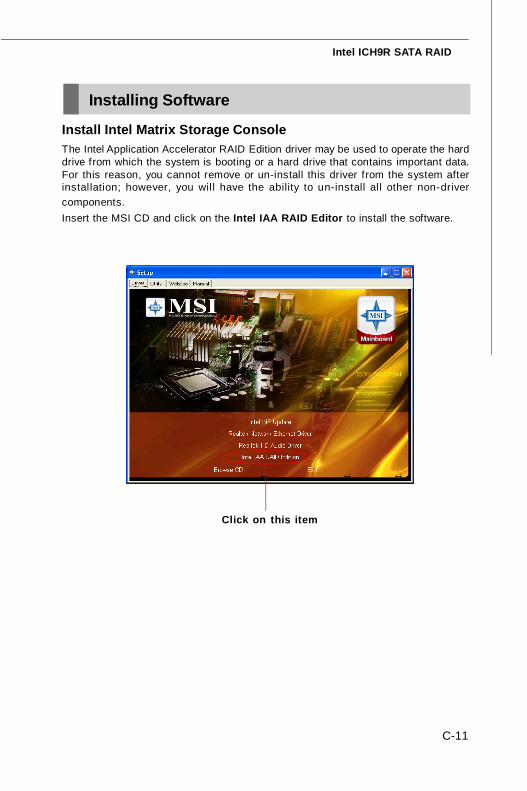
C-11
Intel ICH9R SATA RAID
Install Intel Matrix Storage ConsoleThe Intel Application Accelerator RAID Edition driver may be used to operate the harddrive from which the system is booting or a hard drive that contains important data.For this reason, you cannot remove or un-install this driver from the system afterinstallation; however, you wil l have the ability to un-install all other non-drivercomponents.Insert the MSI CD and click on the Intel IAA RAID Editor to install the software.
Click on this item
Installing Software
7345v1.0-C_ICH9R RAID.p65 2007/5/11, 下午 02:0311
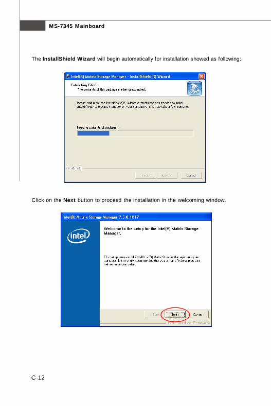
MS-7345 Mainboard
C-12
The InstallShield Wizard will begin automatically for installation showed as following:
Click on the Next button to proceed the installation in the welcoming window.
7345v1.0-C_ICH9R RAID.p65 2007/5/11, 下午 02:0312
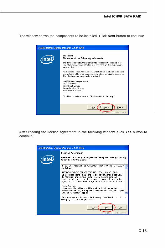
C-13
Intel ICH9R SATA RAID
After reading the license agreement in the following window, click Yes button tocontinue.
The window shows the components to be installed. Click Next button to continue.
7345v1.0-C_ICH9R RAID.p65 2007/5/11, 下午 02:0313

MS-7345 Mainboard
C-14
Once the installation is complete, the following window appears.
The following window appears to show the Readme File Information. It shows thesystem requirements and installation information.
7345v1.0-C_ICH9R RAID.p65 2007/5/11, 下午 02:0314
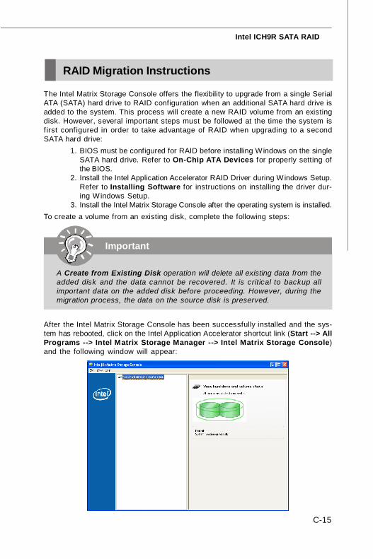
C-15
Intel ICH9R SATA RAID
RAID Migration Instructions
Important
A Create from Existing Disk operation will delete all existing data from theadded disk and the data cannot be recovered. It is critical to backup allimportant data on the added disk before proceeding. However, during themigration process, the data on the source disk is preserved.
The Intel Matrix Storage Console offers the flexibility to upgrade from a single SerialATA (SATA) hard drive to RAID configuration when an additional SATA hard drive isadded to the system. This process will create a new RAID volume from an existingdisk. However, several important steps must be followed at the time the system isfirst configured in order to take advantage of RAID when upgrading to a secondSATA hard drive:
1. BIOS must be configured for RAID before installing Windows on the singleSATA hard drive. Refer to On-Chip ATA Devices for properly setting ofthe BIOS.
2. Install the Intel Application Accelerator RAID Driver during Windows Setup.Refer to Installing Software for instructions on installing the driver dur-ing Windows Setup.
3. Install the Intel Matrix Storage Console after the operating system is installed.To create a volume from an existing disk, complete the following steps:
After the Intel Matrix Storage Console has been successfully installed and the sys-tem has rebooted, click on the Intel Application Accelerator shortcut link (Start --> AllPrograms --> Intel Matrix Storage Manager --> Intel Matrix Storage Console)and the following window will appear:
7345v1.0-C_ICH9R RAID.p65 2007/5/11, 下午 02:0315
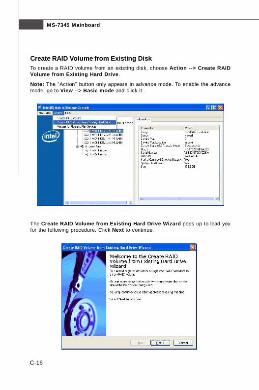
MS-7345 Mainboard
C-16
Create RAID Volume from Existing DiskTo create a RAID volume from an existing disk, choose Action --> Create RAIDVolume from Existing Hard Drive.
Note: The “Action” button only appears in advance mode. To enable the advancemode, go to View --> Basic mode and click it.
The Create RAID Volume from Existing Hard Drive Wizard pops up to lead youfor the following procedure. Click Next to continue.
7345v1.0-C_ICH9R RAID.p65 2007/5/11, 下午 02:0416
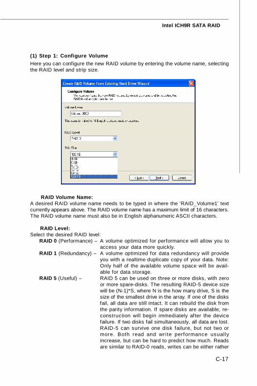
C-17
Intel ICH9R SATA RAID
(1) Step 1: Configure VolumeHere you can configure the new RAID volume by entering the volume name, selectingthe RAID level and strip size.
Ü RAID Volume Name:A desired RAID volume name needs to be typed in where the ‘RAID_Volume1’ textcurrently appears above. The RAID volume name has a maximum limit of 16 characters.The RAID volume name must also be in English alphanumeric ASCII characters.
Ü RAID Level:Select the desired RAID level:
RAID 0 (Performance) – A volume optimized for performance will allow you toaccess your data more quickly.
RAID 1 (Redundancy) – A volume optimized for data redundancy will provideyou with a realtime duplicate copy of your data. Note:Only half of the available volume space will be avail-able for data storage.
RAID 5 (Useful) – RAID 5 can be used on three or more disks, with zeroor more spare-disks. The resulting RAID-5 device sizewill be (N-1)*S, where N is the how many drive, S is thesize of the smallest drive in the array. If one of the disksfail, all data are still intact. It can rebuild the disk fromthe parity information. If spare disks are available, re-construction will begin immediately after the devicefailure. If two disks fail simultaneously, all data are lost.RAID-5 can survive one disk failure, but not two ormore. Both read and wri te performance usuallyincrease, but can be hard to predict how much. Readsare similar to RAID-0 reads, writes can be either rather
7345v1.0-C_ICH9R RAID.p65 2007/5/11, 下午 02:0417
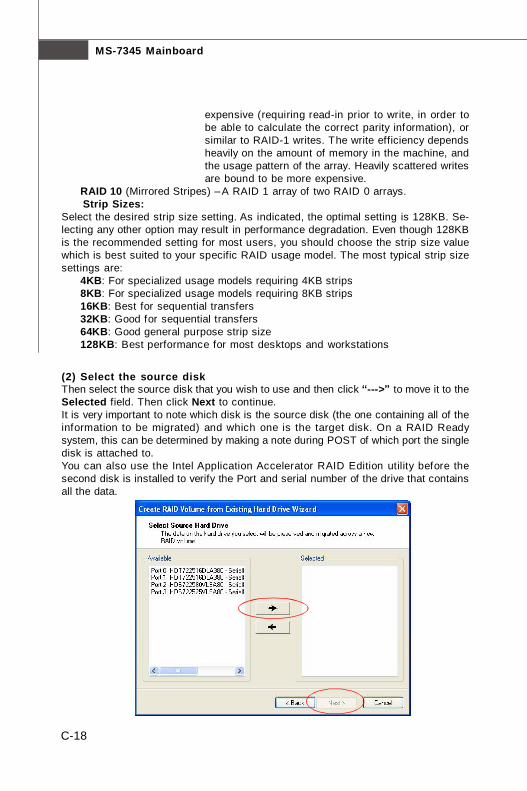
MS-7345 Mainboard
C-18
expensive (requiring read-in prior to write, in order tobe able to calculate the correct parity information), orsimilar to RAID-1 writes. The write efficiency dependsheavily on the amount of memory in the machine, andthe usage pattern of the array. Heavily scattered writesare bound to be more expensive.
RAID 10 (Mirrored Stripes) –A RAID 1 array of two RAID 0 arrays.Ü Strip Sizes:Select the desired strip size setting. As indicated, the optimal setting is 128KB. Se-lecting any other option may result in performance degradation. Even though 128KBis the recommended setting for most users, you should choose the strip size valuewhich is best suited to your specific RAID usage model. The most typical strip sizesettings are:
4KB: For specialized usage models requiring 4KB strips8KB: For specialized usage models requiring 8KB strips16KB: Best for sequential transfers32KB: Good for sequential transfers64KB: Good general purpose strip size128KB: Best performance for most desktops and workstations
(2) Select the source diskThen select the source disk that you wish to use and then click “--->” to move it to theSelected field. Then click Next to continue.It is very important to note which disk is the source disk (the one containing all of theinformation to be migrated) and which one is the target disk. On a RAID Readysystem, this can be determined by making a note during POST of which port the singledisk is attached to.You can also use the Intel Application Accelerator RAID Edition utility before thesecond disk is installed to verify the Port and serial number of the drive that containsall the data.
7345v1.0-C_ICH9R RAID.p65 2007/5/11, 下午 02:0418
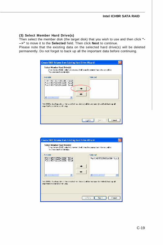
C-19
Intel ICH9R SATA RAID
(3) Select Member Hard Drive(s)Then select the member disk (the target disk) that you wish to use and then click “--->” to move it to the Selected field. Then click Next to continue.Please note that the existing data on the selected hard drive(s) will be deletedpermanently. Do not forget to back up all the important data before continuing.
7345v1.0-C_ICH9R RAID.p65 2007/5/11, 下午 02:0419
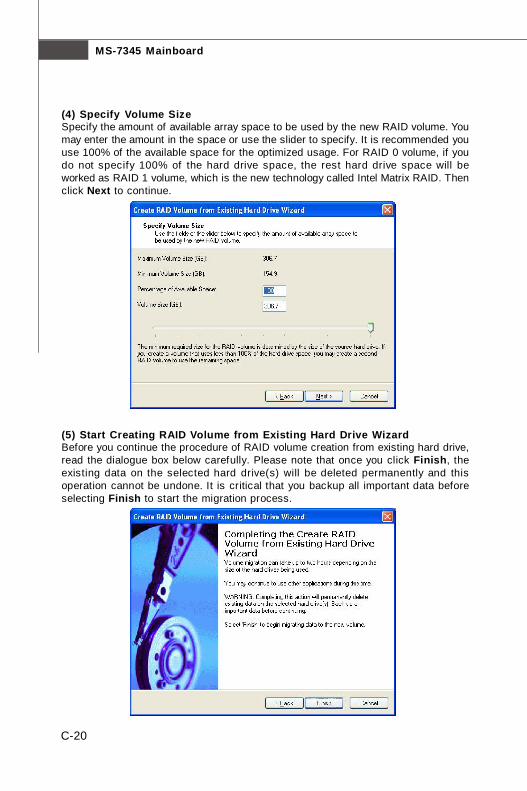
MS-7345 Mainboard
C-20
(4) Specify Volume SizeSpecify the amount of available array space to be used by the new RAID volume. Youmay enter the amount in the space or use the slider to specify. It is recommended youuse 100% of the available space for the optimized usage. For RAID 0 volume, if youdo not specify 100% of the hard drive space, the rest hard drive space will beworked as RAID 1 volume, which is the new technology called Intel Matrix RAID. Thenclick Next to continue.
(5) Start Creating RAID Volume from Existing Hard Drive WizardBefore you continue the procedure of RAID volume creation from existing hard drive,read the dialogue box below carefully. Please note that once you click Finish, theexisting data on the selected hard drive(s) will be deleted permanently and thisoperation cannot be undone. It is critical that you backup all important data beforeselecting Finish to start the migration process.
7345v1.0-C_ICH9R RAID.p65 2007/5/11, 下午 02:0420
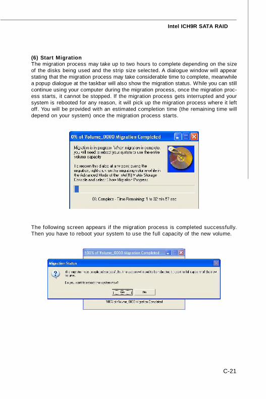
C-21
Intel ICH9R SATA RAID
(6) Start MigrationThe migration process may take up to two hours to complete depending on the sizeof the disks being used and the strip size selected. A dialogue window will appearstating that the migration process may take considerable time to complete, meanwhilea popup dialogue at the taskbar will also show the migration status. While you can stillcontinue using your computer during the migration process, once the migration proc-ess starts, it cannot be stopped. If the migration process gets interrupted and yoursystem is rebooted for any reason, it will pick up the migration process where it leftoff. You will be provided with an estimated completion time (the remaining time willdepend on your system) once the migration process starts.
The following screen appears if the migration process is completed successfully.Then you have to reboot your system to use the full capacity of the new volume.
7345v1.0-C_ICH9R RAID.p65 2007/5/11, 下午 02:0421
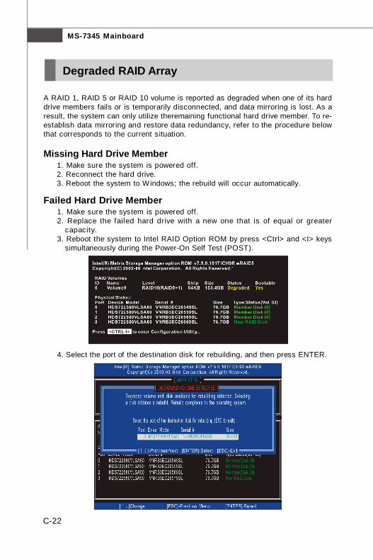
MS-7345 Mainboard
C-22
A RAID 1, RAID 5 or RAID 10 volume is reported as degraded when one of its harddrive members fails or is temporarily disconnected, and data mirroring is lost. As aresult, the system can only utilize theremaining functional hard drive member. To re-establish data mirroring and restore data redundancy, refer to the procedure belowthat corresponds to the current situation.
Missing Hard Drive Member1. Make sure the system is powered off.2. Reconnect the hard drive.3. Reboot the system to Windows; the rebuild will occur automatically.
Failed Hard Drive Member1. Make sure the system is powered off.2. Replace the failed hard drive with a new one that is of equal or greater
capacity.3. Reboot the system to Intel RAID Option ROM by press <Ctrl> and <I> keys
simultaneously during the Power-On Self Test (POST).
Degraded RAID Array
4. Select the port of the destination disk for rebuilding, and then press ENTER.
7345v1.0-C_ICH9R RAID.p65 2007/5/11, 下午 02:0422
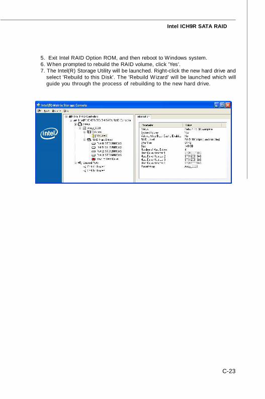
C-23
Intel ICH9R SATA RAID
5. Exit Intel RAID Option ROM, and then reboot to Windows system.6. When prompted to rebuild the RAID volume, click 'Yes'.7. The Intel(R) Storage Utility will be launched. Right-click the new hard drive and
select 'Rebuild to this Disk'. The 'Rebuild Wizard' will be launched which willguide you through the process of rebuilding to the new hard drive.
7345v1.0-C_ICH9R RAID.p65 2007/5/11, 下午 02:0423