msf soft starter - · pdf file2 safety the soft starter should be installed in a cabinet or...
TRANSCRIPT

MSFSOFT STARTER
INSTRUCTION MANUAL
Document number: 01-1363-01Edition: r2Date of release: 2001-04-20© Copyright Emotron AB 2000Emotron retain the right to change specifications and illustrations in the text, without prior notification. The contents of this document may not be copied without the explicit permission of Emotron AB.
Valid for the following Soft starter Models:MSF-017 to MSF-1400

2
SafetyThe soft starter should be installed in a cabinet or in anelectrical control room.• The device must be installed by trained personnel.• Disconnect all power sources before servicing.• Always use standard commercial fuses, slow blow
e.g. type gl, gG, to protect the wiring and preventshort circuiting. To protect the thyristors againstshort-circuit currents, superfast semiconductor fusescan be used if preferred. The normal guarantee isvalid even if superfast semiconductor fuses are notused.
Operating and maintenance personnel1. Read the whole Instruction Manual before install-
ing and putting the equipment into operation. 2. During all work (operation, maintenance, repairs,
etc.) observe the switch-off procedures given in thisinstruction as well as any other operatinginstruction for the driven machine or system. SeeEmergency below.
3. The operator must avoid any working methodswhich reduce the safety of the device.
4. The operator must do what he can to ensure thatno unauthorised person is working on the device.
5. The operator must immediately report any changesto the device which reduce its safety to the user.
6. The user must undertake all necessary measures tooperate the device in perfect condition only.
Installation of spare partsWe expressly point out that any spare parts and accesso-ries not supplied by us have also not been tested orapproved by us.
Installing and/or using such products can have anegative effect on the characteristics designed for yourdevice. The manufacturer is not liable for damage aris-ing as a result of using non-original parts and accesso-ries.
EmergencyYou can switch the device off at any time with themains switch connected in front of the soft starter (bothmotor and control voltage must be switched off).
Dismantling and scrappingThe enclosure of the soft starter is made of recyclablematerial as aluminium, iron and plastic. Legal require-ments for disposal and recycling of these materials mustbe complied with.
The soft starter contains a number of componentsdemanding special treatment, as for example thyristors.The circuit board contain small amounts of tin andlead. Legal requirements for disposal and recycling ofthese materials must be complied with.
S A F E T Y I N S T R U C T I O N S

3
C O N T E N T S
1 . G E N E R A L I N F O R M A T I O N . . . . . . 6
1.1 Integrated safety systems ...............................61.2 Safety measures .............................................61.3 Notes to the Instruction Manual ......................61.4 How to use the Instruction Manual ..................61.5 Standards .......................................................61.6 Tests in accordance with norm EN60204 .........61.7 Inspection at delivery ......................................71.7.1 Transport and packing .....................................71.8 Unpacking of MSF-310 and larger types ...........7
2 . D E S C R I P T I O N . . . . . . . . . . . . . . . . . . . 8
2.1 General ...........................................................82.2 MSF control methods ......................................92.2.1 General features .............................................9
3 . H O W T O G E T S T A R T E D . . . . . . . 10
3.1 Checklist ......................................................103.2 Main functions/Applications .........................103.3 Motor Data ...................................................103.4 Setting of the start and stop ramps ...............113.5 Setting the start command ............................123.6 Viewing the motor current .............................123.7 Starting ........................................................12
4 . A P P L I C A T I O N S A N D F U N C T I O N SS E L E C T I O N . . . . . . . . . . . . . . . . . . . . . 13
4.1 Soft starter rating according to AC53a ..........134.2 Soft starter rating according to AC53b ..........134.3 MSF Soft starter ratings ................................144.4 The Application Ratings List ..........................144.5 The Application Functions List .......................164.6 Function and combination matrix ...................194.7 Special condition ..........................................204.7.1 Small motor or low load .................................204.7.2 Ambient temperature below 0×C ...................204.7.3 Phase compensation capacitor ......................204.7.4 Pole-changing contactor and two speed motor 204.7.5 Shielded motor cable ....................................204.7.6 Slip ring motors ............................................204.7.7 Pump control with soft starter and frequency
inverter together ...........................................204.7.8 Starting with counter clockwise rotating loads204.7.9 Running motors in parallel .............................204.7.10 How to calculate heat dissipation in cabinets .204.7.11 Insulation test on motor ................................204.7.12 Operation above 1000 m ...............................204.7.13 Reversing .....................................................20
5 . O P E R A T I O N O F T H E S O F T S T A R T E R . . . . . . . . . . . . . . . . . . . . . . . . 21
5.1 General description of user interface ................... 215.2 PPU unit .......................................................215.3 LED display ...................................................225.4 The Menu Structure ......................................225.5 The keys .......................................................23
5.6 Keyboard lock ...............................................235.7 Overview of soft starter opera-tion and
parameter set-up. .........................................23
6 . I N S T A L L A T I O N A N D C O N N E C T I O N . . . . . . . . . . . . . . . . . . . 24
6.1 Installation of the soft starter in a cabinet .....246.2 Connections .................................................286.3 Connection and setting on the
PCB control card ..........................................326.4 Minimum wiring ............................................336.5 Wiring examples ............................................34
7 . F U N C T I O N A L D E S C R I P T I O N S E T - U P M E N U . . . . . . . . . . . . . . . . . . 35
7.1 Ramp up/down parameters ...........................367.1.1 RMS current [005] .......................................367.2 Start/stop/reset command ...........................377.2.1 2-wire start/stop with automatic reset
at start .........................................................377.2.2 2-wire start/stop with separate reset ............377.2.3 3-wire start/stop with automatic reset at
start. ............................................................377.3 Menu expansion setting. ...............................387.4 Voltage control dual ramp .............................387.5 Torque control parameters ............................397.6 Current limit (Main Function) ........................397.6.1 Voltage ramp with current limit .....................397.6.2 Current limit .................................................407.7 Pump control (Main Function) .......................407.8 Analogue Input Control (Main Function) .........417.9 Full voltage start, D.O.L. (Main Function) ......417.10 Torque control (Main function) ......................427.11 Torque boost ................................................437.12 Bypass .........................................................437.13 Power Factor Control ....................................467.14 Brake functions ............................................467.15 Slow speed and Jog functions ........................487.15.1 Slow speed controlled by an external signal. ..487.15.2 Slow speed during a selected time ................497.15.3 Jog Functions ...............................................497.15.4 DC-brake after slow speed at stop [040] .......497.16 Motor data setting ........................................507.17 Programmable relay K1 and K2 .....................517.18 Analogue output ...........................................527.19 Digital input selection ...................................537.20 Parameter Set ..............................................547.21 Motor protection, overload (F2 alarm) ...........557.22 Mains protection .........................................567.23 Application protection (load monitor) .............577.23.1 Load monitor max and min/protection
(F6 and F7 alarms) .......................................577.23.2 Pre-alarm ......................................................587.24 Resume alarms .............................................617.24.1 Phase input failure F1 ...................................617.24.2 Run at current limit time-out F4 .....................617.25 Slow speed with JOG .....................................61

4
7.26 Automatic return menu .................................627.27 Communication option, related Parameters ....627.28 Reset to factory setting [199] .......................637.29 View operation ..............................................637.30 Keyboard lock ...............................................657.31 Alarm list ......................................................65
8 . P R O T E C T I O N A N D A L A R M . . . . 66
8.1 Alarm description ..........................................668.1.1 Alarm with stop and requiring a separate reset668.1.2 Alarm with stop and requiring only a new
start command .............................................668.1.3 Alarm with continue run ................................668.2 Alarm overview .............................................67
9 . T R O U B L E S H O O T I N G . . . . . . . . . . 68
9.1 Fault, cause and solution ..............................68
1 0 . M A I N T E N A N C E . . . . . . . . . . . . . . . . . 71
1 1 . O P T I O N S . . . . . . . . . . . . . . . . . . . . . . . . 72
11.1 Serial communication ....................................7211.2 Field bus systems .........................................7211.3 External PPU. ...............................................7211.3.1 Cable kit for external current transformers......7211.4 Terminal clamp .............................................73
1 2 . T E C H N I C A L D A T A . . . . . . . . . . . . . . 74
1 3 . S E T - U P M E N U L I S T . . . . . . . . . . . . 79
1 4 . I N D E X . . . . . . . . . . . . . . . . . . . . . . . . . . . 82
R E P R E S E N T A T I O N . . . . . . . . . . . . . 85
List of tablesTable 1 Applications Rating List ............................15Table 2 Application Function List ..........................17Table 3 Combination matrix ..................................19Table 4 Start/stop combination. ...........................19Table 5 The keys ..................................................23Table 6 Control modes ..........................................23Table 7 MSF-017 to MSF-250. ...............................25Table 8 MSF-017 to MSF-250 ................................25Table 9 MSF-310 to MSF-1400 ..............................25Table 10 MSF-310 to MSF-1400. .............................25Table 11 Busbar distances ............................................26Table 12 PCB Terminals ..........................................32Table 13 Set-up Menu overview ...............................35

5
List of figuresFig. 1 Scope of delivery. ...........................................7Fig. 2 Unpacking of MSF-310 and larger models. .......7Fig. 3 Voltage control ...............................................8Fig. 4 Current control ...............................................8Fig. 5 Torque control ................................................8Fig. 6 Standard wiring. ..............................................10Fig. 7 Example of start ramp with main
function voltage ramp. ....................................12Fig. 8 Rating example AC53a. ..................................13Fig. 9 Duty cycle, non bypass. ..................................13Fig. 10 Rating example AC53b. ..................................13Fig. 11 Duty cycle, bypassed ......................................13Fig. 12 MSF soft starter models. .................................21Fig. 13 PPU unit. ........................................................21Fig. 14 LED indication at different operation situation. .22Fig. 15 Menu structure. ..............................................22Fig. 16 MSF-017 to MSF-250 dimensions. ...................24Fig. 17 Hole pattern for MSF-017 to MSF-250 .............24Fig. 18 Hole pattern for MSF-170 to MSF-250
with upper mounting bracket instead of DIN-rail. ......................................................24
Fig. 19 MSF -310 to MSF -835. ...................................26Fig. 20 Hole pattern for screw attachment,
MSF-310 to MSF-835. Hole distance (mm). .....26Fig. 21 Busbar distances MSF -310 to MSF -835. ........26Fig. 22 MSF -1000 to -1400 ........................................27Fig. 23 Hole pattern busbar MSF -1000 to -1400. ........27Fig. 24 Connection of MSF-017 to MSF -085. ..............28Fig. 25 Connection of MSF-110 to MSF-145. ...............29Fig. 26 Connection of MSF-170 to MSF-250 ................30Fig. 27 Connection of MSF-170 to MSF-1400. .............31Fig. 28 Connections on the PCB, control card. ............32Fig. 29 Wiring circuit, “Minimum wiring”. ....................33Fig. 30 Analogue input control, parameter set,
analogue output and PTC input. .......................34Fig. 31 Forward/reverse wiring circuit. ........................34Fig. 32 Menu numbers for start/stop ramps,
initial voltage at start and step down voltage at stop. ..............................................36
Fig. 33 Menu numbers for dual voltage ramp at start/stop, initial voltage at start and step down-voltage at stop. ......................................38
Fig. 34 Current limit ...................................................39Fig. 35 Current limit ...................................................40Fig. 36 Pump control ..................................................40Fig. 37 Wiring for analogue input. ...............................41Fig. 38 Setting voltage or current for analogue input. ..41Fig. 39 Full voltage start. ...........................................41Fig. 40 Torque control at start/stop. ...........................42Fig. 41 Current and speed in torque control. ................42Fig. 42 The principle of the Torque Booster when
starting the motor in voltage ramp mode. ........43Fig. 43 Bypass wiring example MSF 310-1400. ...........44Fig. 44 Current transformer position when Bypass
MSF-017 to MSF-250. .....................................45Fig. 45 Current transformer position when Bypass
MSF-310 to MSF-1400. ...................................45Fig. 46 Braking time ...................................................46Fig. 47 Soft brake wiring example. ..............................47Fig. 48 Slow speed controlled by an external signal. ....48Fig. 49 Slow speed at start/stop during a
selected time. ................................................49Fig. 50 Start/stop sequence and relay function
“Operation” and “Full voltage”. .......................51Fig. 51 Wiring for analogue output. .............................52Fig. 52 Setting of current or voltage output. ................52Fig. 53 Setting of J1 for current or voltage control. ......53
Fig. 54 Wiring for slow speed external input. ...............53Fig. 55 Parameter overview ........................................54Fig. 56 Connection of external control inputs. .............54Fig. 57 The thermal curve ...........................................55Fig. 58 Load monitor alarm functions. .........................60Fig. 59 The 2 Jog keys. ...............................................61Fig. 60 Option RS232/485 .........................................72Fig. 61 Option Profibus ...............................................72Fig. 62 Shows an example of the External PPU
after it has been built in. .................................72Fig. 63 Cable kit ........................................................72Fig. 64 The terminal clamp. ........................................73

6 GENERAL INFORMATION
1 . G E N E R A L I N F O R M A T I O N
1.1 Integrated safety systemsThe device is fitted with a protection system whichreacts to:• Over temperature.• Voltage unbalance. • Over- and under voltage.• Phase reversal• Phase loss• Motor overload protection thermal and PTC.• Motor load monitor, protecting machine or process
max or min alarm• Starts per hour limitation
The soft starter is fitted with a connection for pro-tective earth (PE).
MSF soft starters are all enclosed IP 20, exceptMSF-1000 and MSF-1400 which are delivered as openchassi IP00.
1.2 Safety measuresThese instructions are a constituent part of the deviceand must be:• Available to competent personnel at all times.• Read prior to installation of the device.• Observed with regard to safety, warnings and infor-
mation given.
The tasks in these instructions are described so thatthey can be understood by people trained in electricalengineering. Such personnel must have appropriatetools and testing instruments available. Such personnelmust have been trained in safe working methods.
The safety measures laid down in DIN norm VDE0100 must be guaranteed.
The user must obtain any general and local operatingpermits and meet any requirements regarding:• Safety of personnel.• Product disposal.• Environmental protection.
NOTE! The safety measures must remain in force at all times. Should questions or uncertainties arise, please contact your local sales outlet.
1.3 Notes to the Instruction Manual
WARNING! Warnings are marked with a warning triangle.
Serial numberThe information given in these instructions onlyapplies to the device with the serial number given onthe label on the front page. A plate with the serialnumber is fixed to the device.
ImportantFor all enquiries and spare parts orders, please quotethe correct name of the device and serial number toensure that your inquiry or order is dealt with correctlyand swiftly.
NOTE! These instructions only apply to the soft starters having the serial number given on the front page, and not for all models.
1.4 How to use the Instruction Manual
This instruction manual tells you how to install andoperate the MSF soft starter. Read the whole Instruc-tion Manual before installing and putting the unit intooperation. For simple start-up, read chapter 2. page 8to chapter 3. page 10.
Once you are familiar with the soft starter, you canoperate it from the keyboard by referring to the chap-ter 13. page 79. This chapter describes all the functionsand possible setting.
1.5 StandardsThe device is manufactured in accordance with theseregulations.• IEC 947-4-2• EN 60204-1 Electrical equipment of machines, part
1, General requirements and VDE 0113. • EN 50081-2, EMC Emission• EN 50081-1, EMC Emission with bypass• EN 50082-2, EMC Immunity• GOST• UL508
1.6 Tests in accordance with norm EN60204
Before leaving the factory, the device was subjected tothe following tests:• Through connection of earthing system;
a) visual inspection.b) check that earthing wire is firmly connected.
• Insulation• Voltage• Function
!

GENERAL INFORMATION 7
1.7 Inspection at delivery
Fig. 1 Scope of delivery.
1.7.1 Transport and packingThe device is packed in a carton or plywood box fordelivery. The outer packaging can be returned. Thedevices are carefully checked and packed before dis-patch, but transport damage cannot be ruled out.
Check on receipt:• Check that the goods are complete as listed on the
delivery note, see type no. etc. on the rating plate.
Is the packaging damaged?• Check the goods for damage (visual check).
If you have cause for complaintIf the goods have been damaged in transport:• Contact the transport company or the supplier
immediately.• Keep the packaging (for inspection by the transport
company or for returning the device).
Packaging for returning the device• Pack the device so that it is shock-resistant.
Intermediate storageAfter delivery or after it has been dismounted, thedevice can be stored before further use in a dry room.
1.8 Unpacking of MSF-310 and larger types
The soft starter is attached to the plywood box/loading stool by screws, and the soft starter must be unpacked as follows:1. Open only the securing plates at the bottom of the
box (bend downwards). Then lift up the box fromthe loading stool, both top and sides in one piece.
2. Loosen the three (3 pcs) screws on the front coverof the soft starter, down by the lower logo.
3. Push up the front cover about 20 mm so that thefront cover can be removed.
4. Remove the two (2 pcs) mounting screws at thebottom of the soft starter.
5. Lift up the soft starter at the bottom about 10 mmand then push backwards about 20 mm so that thesoft starter can be removed from the mountinghooks* at the top. The hooks are placed under thebottom plate and cannot be removed until the softstarter is pulled out.
6. Loosen the screws (2 pcs) for the mounting hooksand remove the hooks.
7. The hooks are used as an upper support for mount-ing the soft starter.
Fig. 2 Unpacking of MSF-310 and larger models.
MSFSOFT STARTERINSTRUCTION MANUAL

8 DESCRIPTION
2 . D E S C R I P T I O N
2.1 GeneralThe MSF is installed directly between the mains andthe supply cable to the motor. If a mains contactor isused it can be activated by the integrated K1 relay.
The MSF is developed for soft starting, stopping andbraking three-phase motors.
There are 3 different kinds of soft starting controlmethods:• Control method 1-Phase
The single phase controlled soft starters provide only a reduction in starting torque no control of current or torque. These starters need a main and bypass contactor as well as external motor protec-tions. This is a open loop voltage controller. These starters are mainly in the power up to 7.5 kW.
• Control method 2-PhaseThe two phase starters can start a motor without a mains contactor, but in that case voltage still is present at the motor when it´s stopped. These start-ers are mainly in the power up to 22 kW.
• Control method 3-PhaseIn the three phase Soft Starters there are different technologies:• Voltage control• Current control• Torque control
Voltage controlThis method is the most used control method. Thestarter gives a smooth start but doesn’t get any feedbackon current or torque. The typical settings to optimize avoltage ramp are: Initial voltage, ramp time, dual ramptime.
Fig. 3 Voltage control
Current controlThe voltage ramp can be used with a current limitwhich stops the voltage ramp when the set maximumcurrent level is reached. The maximum current level isthe main setting and must be set by the user dependingthe maximum current allowed for the application.
Fig. 4 Current control
Torque controlIs the most sufficient way of starting motors. Unlikevoltage and current based systems the soft starter moni-tors the torque need and allows to start with the lowestpossible current. Using a closed loop torque controlleralso linear ramps are possible. The voltage ramp can nothold back the motor starting torque this results in acurrent peak and unlinear ramps. In the current rampthere will be no peak current, but a higher current fora longer period of time during the start compared totorque control. Current starting doesn’t give linearramps. The linear ramps are very important in manyapplications. For an example, to stop a pump with anunlinear ramp will give water hammer. Soft starterswhich doesn’t monitor the torque, will start and stop tofast if the load is lighter than the setting of current orramp time.
Fig. 5 Torque control
03-F116
FLC
Current (A)
Time
03-F111
FLC
Current (A)
Time
CurrentLimit
03-F113
FLC
Current (A)
Time

DESCRIPTION 9
2.2 MSF control methodsMSF Soft Starters control all three phases supplied tothe motor. It manages all the 3 possible starting meth-ods where the closed loop Torque control is the mostefficient way of starting and stopping motors.
2.2.1 General featuresAs mentioned above soft starters offer you several fea-tures and the following functions are available: • Torque controlled start and stop• Current limit control at start• Application “Pump”• External analogue input control• Torque booster at start• Full voltage start (D.O.L)• Dual voltage ramp at start and stop• Bypass• Dynamic DC-brake or Softbrake• Slow speed at start and stop• Jogging forward and reverse• Four parameter sets• Analogue output indicating current, power
or voltage• Viewing of current, voltage, power, torque, power
consumption, elapsed time etc.• Integrated safety system acc. to § 1.1, page 6, with
an alarm list.

10 HOW TO GET STARTED
3 . H O W T O G E T S T A R T E D
Fig. 6 Standard wiring.
This chapter describes briefly the set-up for basic softstart and soft stop by using the default “Voltage Ramp”function.
WARNING! Mounting, wiring and setting the device into operation must be carried out by properly trained personnel. Before set-up, make sure that the installation is according to chapter 6. page 24 and the Checklist below.
3.1 Checklist• Mount the soft starter in accordance with chapter 6.
page 24.• Consider the power loss at rated current when
dimensioning a cabinet, max. ambient temperatureis 40ºC (see chapter 12. page 74).
• Connect the motor circuit according to Fig. 6.• Connect the protective earth.• Connect the control voltage to terminals 01 and 02
(100 - 240 VAC or 380-500 VAC).• Connect relay K1 (PCB terminals 21 and 22) to the
contactor - the soft starter then controls the contac-tor.
• Connect PCB terminals 12 and 13 to, e.g., a 2-wayswitch (closing non-return) or a PLC, etc., toobtain control of soft start/soft stop.1)
• Check that the motor and supply voltage corre-sponds to values on the soft starter’s rating plate.
• Ensure the installation complies with the appropri-ate local regulations.
1) The menu 006 must be put to 01 for start/stop command fromkeyboard.
3.2 Main functions/Applications
WARNING! Make sure that all safety measures have been taken before switching on the supply.
Switch on the control voltage (normally 1 x 230 V), allsegments in the display and the two LED’s will be illu-minated for a few seconds. Then the display will showmenu 001. An illuminated display indicates there issupply voltage on the PCB. Check that you have mainsvoltage on the mains contactor or on the thyristors.The settings are carried out according to following:
The first step in the settings is to set menu 007 and008 to “ON” to reach the main functions 020-025 andmotor data 041-046.
NOTE! The main function is chosen according to the application. The tables in the applications and functions selection (table 1, page 15), gives the information to choose the proper main function.
3.3 Motor DataSet the data, according to the motor type plate toobtain optimal settings for starting, stopping and motorprotection.
NOTE! The default settings are for a standard 4-pole motor acc. to the nominal power of the soft-starter. The soft starter will run even if no specific motor data is selected, but the performance will not be optimal.
03-F17
Q1
L1
L2
L3
N
3121 22 23 24 33K1 K2 K3L1 L2 L3 PE 01 02 PE
13
start0
1
/stop
PET2T1 T3 11 12 1514 16 17 18 19
32 69 70
7775 76
PE
U V W PE
M3 ~
!
!

HOW TO GET STARTED 11
NOTE! Now go back to menu 007 and set it to “oFF” and then to menu 001.
3.4 Setting of the start and stop ramps
The menu´s 002 and 003 can now be set to adjust thestart ramp up time and the stop ramp down time.
Estimate the starting-time for the motor/machine. Set”ramp up time” at start (1-60 sec).Key “ENTER ” to confirm new value. Key “NEXT “, “PREV ” to change menu.
Set ”ramp down time” at stop (2-120 s).“oFF” if only soft start requires.
Nominal motor voltage
Default: 400 V
Range: 200-700 V
Nominal motor current
Default: Nominal current soft starter
Range: 25% - 150% of Insoft in Amp
Nominal motor power
Default: Nominal power soft starter
Range: 25% - 300% of Pnsoft in kW
Nominal motor speed
Default: Nominal speed soft starter
Range: 500-3600 rpm
Nominal motor cos phi
Default: 0.86
Range: 0.50-1.00
0 4 1
0 04
0 4 2
4 5
0 4 3
2 2
0 4 4
5 041
0 4 5
8 6.
Nominal frequency
Default: 50 Hz
Range: 50/60 Hz
Start time ramp 1
Default: 10 sec
Range: 1-60 sec
Stop time ramp 1
Default: oFF
Range: oFF, 2-120 sec
0 4 6
5 0
0 0 2
1 0
0 0 4
F Fo

12 HOW TO GET STARTED
3.5 Setting the start commandAs default the start command is set for remote opera-tion via terminal 11, 12 and 13. For easy commission-ing it is possible to set the start command on the startkey on the keyboards. This is set with menu 006.
Menu 006 must be set to 1 to be able to operate fromkeyboard.
NOTE! Factory default setting is remote control (2).
To start and stop from the keyboard, the “START/STOP” key is used.
To reset from the keyboard, the “ENTER /RESET” key is used. A reset can be given both whenthe motor is running and when the motor is stopped.A reset by the keyboard will not start or stop themotor.
3.6 Viewing the motor currentSet the display to menu 005. Now the Motor currentcan be viewed on the display.
NOTE! The menu 005 can be selected at any time when the motor is running.
3.7 Starting
WARNING! Make sure that all safety measures have been taken before starting the motor in order to avoid personal injury.
Start the motor by pressing the “START/STOP“ keyon the keyboard or through the remote control, PCBterminal 11, 12 and 13. When the start command isgiven, the mains contactor will be activated by relay K1(PCB terminal 21 and 22), and the motor then startssoftly.
Fig. 7 Example of start ramp with main function voltage ramp.
Selection of control mode
Default: 2
Range: 1,2,3
RMS current read-out
Default: -
Range: 0.0-9999 Amp.
0 0 6
2
0 0 5
0. 0
!
03-F116
FLC
Current (A)
Time

APPLICATIONS AND FUNCTIONS SELECTION 13
4 . A P P L I C A T I O N S A N D F U N C T I O N S S E L E C T I O N
This chapter is a guide to select the correct soft starterrating and the selection of the Main function and addi-tional functions for each different application.
To make the right choice the following tools areused:• The norm AC53a.
This norm helps selecting the soft starter rating with regard to duty cycle, starts per hour and maximum starting current.
• The Application Rating List. With this list the soft starter rating can be selected depending on the kind of application used. The list use 2 levels of the AC53a norm. See table 1, page 15.
• The Application Function List. This table gives an complete overview of most common applications and duties. For each applica-tions the menu’s that can be used are given. See table 2, page 17.
• Function and Combination matrix.With these tables it is easy to see which combina-tions of Main and additional functions are possible, see table 3, page 19 and table 4, page 19.
4.1 Soft starter rating according to AC53a
The IEC947-4-2 standard for electronic starters definesAC53a as a norm for dimensioning of a soft starter.
The MSF soft starter is designed for continuousrunning. In the Applications table (table 1, page 15)two levels of AC53a are given. This is also given in thetechnical data tables (see chapter 12. page 74).
Fig. 8 Rating example AC53a.
The above example indicates a current rating of 210Amps with a start current ratio of 5.0 x FLC (1050A)for 30 seconds with a 50% duty cycle and 10 starts perhour.
NOTE! If more than 10 starts/hour or other duty cycles are needed, please contact your supplier.
Fig. 9 Duty cycle, non bypass.
4.2 Soft starter rating according to AC53b
This norm is made for Bypass operation. Because theMSF soft starter is designed for continuous operationthis norm is not used in the selection tables in thischapter.
Fig. 10 Rating example AC53b.
Fig. 11 Duty cycle, bypassed
The above example indicates a current rating of 210Amps with a start current ratio of 5.0 x FLC (1050A)for 30 seconds with a 24-minute period between starts.
210A : AC-53a 5.0 - 30 : 50 - 10
(03-F58)
Starts per hour
On-load factor (on-loadduty cycle as percent-age of operation cycle)
Start time (seconds)
Start current (multipleof FLC)
Rated FLC (Full LoadCurrent) of starterunder prescribed condi-tions
Starts per hour
(03-F60)
TIME
CU
RR
EN
T
StartDuration
Run TimeOffTime
Sta
rt C
urre
nt
Duty Cycle = (Start Duration + Run Time)
(Start Duration + Run Time + Off Time)
210A : AC-53b 5.0 - 30 : 1440
(03-F59)
Off time (seconds between starts)
Start time (seconds)
Start current (multiple of FCL)Rated FLC (Full Load Cur-rent) of starter underprescribed conditions
(03-F61)TIME
CU
RR
EN
T
StartDuration
OffTime
Sta
rt C
urre
nt

14 APPLICATIONS AND FUNCTIONS SELECTION
4.3 MSF Soft starter ratingsAccording to the norms AC53a and AC53b a softstarter can have many current ratings.
NOTE! Because the MSF soft starter is designed for continuous operation the norm AC53b is not used in the application rating list.
With help of the Application Rating List with typicalstarting currents and categories in the AC53a level (seetable 1, page 15 and table 2, page 17) it is easy to selectthe proper soft starter rating with the application.
The Application Rating List uses two levels for theAC53a norm:• AC53a 5.0-30:50-10 (heavy duty)
This level will be able to start all applications and follows directly the type number of the soft starter.Example: MSF 370 is 370 Amps FLC and then 5 time this current in starting.
• AC 53a 3.0-30:50-10 (normal/light duty)This level is for a bit lighter applications and here the MSF can manage a higher FLC.Example: MSF 370 in this norm manage 450 Amps FLC and the 3 times this current in starting
NOTE! To compare Soft Starters it’s important to ensure that not only FLC (Full Load Current) is compared but also that the operating parameters are identical.
4.4 The Application Ratings ListTable 1 gives the Application Ratings List. With thislist the rating for the soft starter and Main Functionmenu can be selected.
Description and use of the table:• Applications.
This column gives the various applications. If the machine or application is not in this list, try to iden-tify a similar machine or application. If in doubt pleas contact your supplier.
• AC53a ratings. The rating according to AC53a norm is here classi-fied in 2 ratings. The first for normal/light duty (3.0-30:50-10) and the second for heavy duty (5.0-30:50-10)
• Typical Starting current.Gives the typical starting current for each applica-tion
• Main Function menu.The Main Function menu is advised here. "25;=1", means: program selection 1 in menu 25.
• Stop function.Gives a possible Stop function if applicable."36;=1 / 38-40", means: program selection 1 in menu 36, also menus 38 to 40 can be selected.
EXAMPLE:Roller Mill:• This is an application for heavy duty,• Typical starting current of 450%. • Main function Torque ramp start (menu 25) will
give the best results.• Stop function Dynamic Brake (menu 36, selection
1) can be used.• As well as the Slow Speed at start and stop (menu
38-40) can be used for better start and stop per-formance.

APPLICATIONS AND FUNCTIONS SELECTION 15
Table 1 Applications Rating List
Applications AC53a 3.0-30:50-10 (normal/light)
AC 53a 5.0-30:50-10
(heavy)
Typical starting
current %
Main function Menu nr.
Stop function Menu nr.
General & Water
Centrifugal Pump x 300 22 22
Submersible Pump x 300 22 22
Conveyor x 300-400 25;=1 36;=1 / 38-40
Compressor: Screw x 300 25 -
Compressor, Reciprocating x 400 25;=1 -
Fan x 300 25;=2 -
Mixer x 400-450 25;=1 -
Agitator x 400 25;=1 -
Metals & Mining
Belt Conveyor x 400 25;=1 36;=1 / 38-40
Dust Collector x 350 25;=1 -
Grinder x 300 25;=1 36;=1
Hammer Mill x 450 25;=1 36;=2
Rock Crusher x 400 25;=1 -
Roller Conveyor x x 350 25;=1 36;=1 / 38-40
Roller Mill x 450 25;=1 36;=1 or 2
Tumbler x 400 25;=1 -
Wire Draw Machine x 450 25;=1 36;=1 or 2
Food Processing
Bottle Washer x 300 25;=2
Centrifuge x 400 25;=1 36;=1 or 2
Dryer x 400 25;=2
Mill x 450 25;=1 36;=1 or 2
Palletiser x 450 25;=1
Separator x 450 25;=1 36;=1 or 2
Slicer x 300 25;=1
Pulp and Paper
Re-Pulper x 450 25;=1
Shredder x 450 25;=1
Trolley x 450 25;=1
Petrochemical
Ball Mill x 450 25;=1
Centrifuge x 400 25;=1 36;=1 or 2
Extruder x 500 25;=1
Screw Conveyor x 400 25;=1
Transport & Machine Tool
Ball Mill x 450 25;=1
Grinder x 350 25;=1 36;=1
Material Conveyor x 400 25;=1 36;=1 / 38-40
Palletiser x 450 25;=1
Press x 350 25;=1
Roller Mill x 450 25;=1
Rotary Table x 400 25;=1 36;=1 / 38-40
Trolley x 450 25;=1
Escalator x 300-400 25;=1
Lumber & Wood Products
Bandsaw x 450 25;=1 36;=1 or 2
Chipper x 450 25;=1 36;=1 or 2
Circular Saw x 350 25;=1 36;=1 or 2
Debarker x 350 25;=1 36;=1 or 2
Planer x 350 25;=1 36;=1 or 2
Sander x 400 25;=1 36;=1 or 2

16 APPLICATIONS AND FUNCTIONS SELECTION
4.5 The Application Functions ListThis list gives an overview of many different applica-tions/duties and a possible solution with one of themany MSF functions.
Description and use of the table:• Application /Duty.
This column gives the various applications and level of duty. If the machine or application is not in this list, try to identify a similar machine or application. If in doubt pleas contact your supplier.
• Problem. This column describes possible problems that are familiar for this kind of application.
• Solution MSF.Gives the possible solution for the problem using one the MSF function.
• Menus.Gives the menu numbers and selection for the MSF function. "25;=1", means: program selection 1 in menu 25."36;=1 / 34,35", means: program selection 1 in menu 36, menus 34 and 35 are related to this func-tion.

APPLICATIONS AND FUNCTIONS SELECTION 17
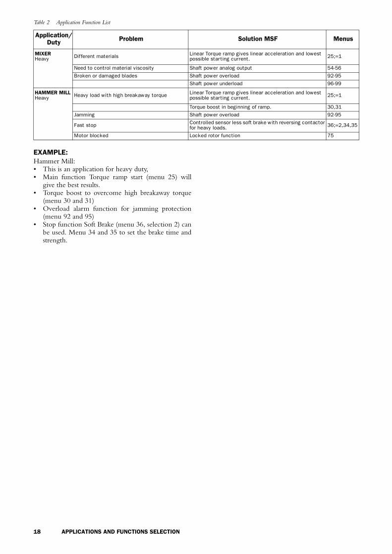
Table 2 Application Function List
Application/Duty Problem Solution MSF Menus
PUMPNormal
Too fast start and stops MSF Pump application with following start/stop features: 22
Non linear ramps Linear ramps without tacho.
Water hammer Torque ramps for quadratic load
High current and peaks during starts.
Pump is going in wrong direction Phase reversal alarm 88
Dry running Shaft power underload 96-99
High load due to dirt in pump Shaft power overload 92-95
COMPRESSORNormal
Mechanical shock for compressor, motor and transmissions Linear Torque ramp or current limit start. 25;=1 or
20,21
Small fuses and low current available.
Screw compressor going in wrong direction Phase sequence alarm 88
Damaged compressor if liquid ammonia enters the compressor screw. Shaft power overload 92-95
Energy consumption due to compressor is run-ning unloaded Shaft power underload 96-99
CONVEYOR Normal/Heavy
Mechanical shocks for transmissions and trans-ported goods. Linear Torque ramp 25;=1
Filling or unloading conveyors Slow speed and accurate position control. 37-40,57,58
Conveyor jammed Shaft power overload 92-95
Conveyor belt or chain is off but the motor is still running Shaft power underload 96-99
Starting after screw conveyor have stopped due to overload. Jogging in reverse direction and then starting in forward.
Conveyor blocked when starting Locked rotor function 75
FAN Normal High starting current in end of ramps Torque ramp for quadratic need 25;=2
Slivering belts.
Fan is going in wrong direction when starting. Catches the motor and going easy to zero speed and then starting in right direction.
Belt or coupling broken Shaft power underload 96-99
Blocked filter or closed damper.
PLANERHeavy
High inertia load with high demands on torque and current control.
Linear Torque ramp gives linear acceleration and lowest possible starting current. 25;=1
Need to stop quick both by emergency and pro-duction efficiency reasons.
Dynamic DC brake without Contactor for medium loads and controlled sensor less soft brake with reversing con-tactor for heavy loads.
36;=1,34,35 36;=2,34,35
High speed lines Conveyor speed set from planer shaft power analog out-put. 54-56
Worn out tool Shaft power overload 92-95
Broken coupling Shaft power underload 96-99
ROCK CRUSHERHeavy
High enertia Linear Torque ramp gives linear acceleration and lowest possible starting current. 25;=1
Heavy load when starting with material Torque boost 30,31
Low power if a diesel powered generator is used.
Wrong material in crusher Shaft power overload 92-95
Vibrations during stop Dynamic DC brake without Contactor 36;=1,34,35
BANDSAWHeavy
High inertia load with high demands on torque and current control.
Linear Torque ramp gives linear acceleration and lowest possible starting current. 25;=1
Need to stop quick both by emergency and pro-duction efficiency reasons.
Dynamic DC brake without Contactor for medium loads and controlled sensor less soft brake with reversing con-tactor for heavy loads.
36;=1,34,35 36;=2,34,35
High speed lines Conveyor speed set from band saw shaft power analog output. 54-56
Worn out saw blade Shaft power overload
Broken coupling, saw blade or belt Shaft power underload
CENTRIFUGEHeavy High inertia load Linear Torque ramp gives linear acceleration and lowest
possible starting current. 25;=1
To high load or unbalanced centrifuge Shaft power overload
Controlled stopDynamic DC brake without Contactor for medium loads and controlled sensor less soft brake with reversing con-tactor for heavy loads.
36;=1,34,35 36;=2,34,35
Need to open centrifuge in a certain position. Braking down to slow speed and then positioning control. 37-40,57,58
18 APPLICATIONS AND FUNCTIONS SELECTION
EXAMPLE:Hammer Mill:• This is an application for heavy duty,• Main function Torque ramp start (menu 25) will
give the best results.• Torque boost to overcome high breakaway torque
(menu 30 and 31)• Overload alarm function for jamming protection
(menu 92 and 95)• Stop function Soft Brake (menu 36, selection 2) can
be used. Menu 34 and 35 to set the brake time andstrength.
MIXER Heavy Different materials Linear Torque ramp gives linear acceleration and lowest
possible starting current. 25;=1
Need to control material viscosity Shaft power analog output 54-56
Broken or damaged blades Shaft power overload 92-95
Shaft power underload 96-99
HAMMER MILLHeavy Heavy load with high breakaway torque Linear Torque ramp gives linear acceleration and lowest
possible starting current. 25;=1
Torque boost in beginning of ramp. 30,31
Jamming Shaft power overload 92-95
Fast stop Controlled sensor less soft brake with reversing contactor for heavy loads. 36;=2,34,35
Motor blocked Locked rotor function 75
Table 2 Application Function List
Application/Duty Problem Solution MSF Menus

APPLICATIONS AND FUNCTIONS SELECTION 19
4.6 Function and combination matrix
Table 3 gives an overview of all possible functions andcombination of functions.
1. Select function in the horizontal “Main Function”column. Only one function can be selected in thiscolumn, at a time.
2. In the vertical column “Additional Functions” youwill find all possible function that can be usedtogether with your selected main function.
By using one parameter set, the following start/stoptable is given.
NOTE! Voltage and torque ramp for starting only with softbrake.
By using different parameter sets for start and stop, it ispossible to combine all start and stop functions.
Table 3 Combination matrix
Main Functions Add
itio
nal f
unct
ions
Dua
l ram
p st
art
Dua
l ram
p st
op
Byp
ass
(032)
Pow
er f
acto
r co
ntro
l (033)
Torq
ue b
oost
(030)
Jogg
ing
wit
h ke
yboa
rd/
term
inal
Tim
er c
ontr
olle
d sl
ow s
peed
Exte
rnal
con
trol
led
slow
spe
ed
Com
plet
e pr
otec
tion
Par
amet
er s
ets
(061)
Dyn
amic
Vec
tor
Bra
ke (
036-1
)
Sof
tbra
ke (
036-2
)
Voltage ramp start/stop (default) X X X X X X X X X X X
Torque control start/stop (menu 025) X X X X X X X X X
Voltage ramp with current limit (menu 020) X X X X X X X X X X X
Current limit start (menu 021) X X X X X X X X X X X
Pump control (menu 022) X X X
Analog input (menu 023) X X
Direct on line start (menu 024) X X X
Table 4 Start/stop combination.
START FUNCTION STO
P F
UN
CTI
ON
Volt
age
ram
p st
op
Torq
ue c
ontr
ol s
top
Pum
p co
ntro
l
Ana
log
inpu
t
Dir
ect
on li
ne s
top
Dyn
amic
Vec
tor
Bra
ke
Sof
tbra
ke
Voltage ramp start X X X X
Torque control start X X X X
Current limit start X X X X
Voltage ramp with current limit X X X X
Pump control X X
Analog input X X
Direct on line start X

20 APPLICATIONS AND FUNCTIONS SELECTION
4.7 Special condition
4.7.1 Small motor or low loadThe minimum load current for the soft starter is 10%of the rated current of the soft starter. Except for theMSE-017 there the min. current is 2 A. ExampleMSE-210, rated current = 210 A. Min. Current 21 A.Please note that this is “min. load current“ and notmin. rated motor current.
4.7.2 Ambient temperature below 0°CFor ambient temperatures below 0°C e.g. an electricalheater must be installed in the cabinet. The soft startercan also be mounted in some other place, due to thatthe distance between the motor and the soft starter isnot critical.
4.7.3 Phase compensation capacitorIf a phase compensation capacitor is to be used, it mustbe connected at the inlet of the soft starter, notbetween the motor and the soft starter.
4.7.4 Pole-changing contactor and two speed motor
The switching device must be connected between theoutput of the soft starter and the motor.
4.7.5 Shielded motor cableIt is not necessary to use shielded wires together withsoft starters. This is due to the very low radiated emis-sions.
NOTE! The soft starter should be wired with shielded con-trol cable to fulfill EMC regulations acc. to § 1.5, page 6.
4.7.6 Slip ring motorsSlip ring motors can not be used together with the softstarter. Unless the motor is rewinded (as a squirrel cagemotor). Or keep the resistors in, please contact yoursupplier.
4.7.7 Pump control with soft starter and frequency inverter together
It is possible e.g. in a pump station with two or morepumps to use one frequency inverter on one pump andsoft starters on each of the other pumps. The flow ofthe pumps can then be controlled by one commoncontrol unit.
4.7.8 Starting with counter clockwise rotating loads
It is possible to start a motor clockwise, even if the loadand motor is rotating counter clockwise e.g. fans.Depending on the speed and the load “in the wrongdirection“ the current can be very high.
4.7.9 Running motors in parallelWhen starting and running motors in parallel the totalamount of the motor current must be equal or lowerthan the connected soft starter. Please note that it is notpossible to make individual settings for each motor.The start ramp can only be set for an average startingramp for all the connected motors. This applies that thestart time may differ from motor to motor. This is alsoeven if the motors are mechanically linked, dependingon the load etc.
4.7.10 How to calculate heat dissipation in cabinets
See chapter 12. page 74 “Technical Data”, “Power lossat rated motor load (IN)“, “Power consumption controlcard“ and “Power consumption fan“. For further cal-culations please contact your local supplier of cabinets,e.g. Rittal.
4.7.11 Insulation test on motorWhen testing the motor with high voltage e.g. insula-tion test the soft starter must be disconnected from themotor. This is due to the fact that the thyristors will beseriously damage by the high peak voltage.
4.7.12 Operation above 1000 mAll ratings are stated at 1000 m over sea level.If a MSF is placed for example at 3000 m it must bederated unless that the ambient temperature is lowerthan 40 C and compensate for this higher pressure.
To get information about motors and drives athigher altitudes please contact your supplier to gettechnical information nr 151.
4.7.13 ReversingMotor reversing is always possible. See Fig. 31 on page34 for the advised connection of the reverse contactors.
At the moment that the mains voltage is switchedon, the phase sequence is monitored by the controlboard. This information is used for the Phase ReverseAlarm (menu 88, see § 7.22, page 56).
However if this alarm is not used (factory default), itis also possible to have the phase reversal contactors inthe input of the soft starter.

OPERATION OF THE SOFT STARTER 21
5 . O P E R A T I O N O F T H E S O F T S T A R T E R
Fig. 12 MSF soft starter models.
5.1 General description of user interface
WARNING! Never operate the soft starter with removed front cover.
To obtain the required operation, a number of parame-ters must be set in the soft starter.
Setting/configuration is done either from the built-in keyboard or by a computer/control system throughthe serial interface or bus (option). Controlling themotor i.e. start/stop, selection of parameter set, is doneeither from the keyboard, through the remote controlinputs or through the serial interface (option).
Setting
WARNING! Make sure that all safety measures have been taken before switching on the supply.
Switch on the supply (normally 1 x 230 V), all seg-ments in the display will light up for a few seconds.Then the display will show menu 001. An illuminateddisplay indicates there is supply voltage on the PCB.
Check that you have voltage on the mains contactoror on the thyristors. To be able to use all extendedfunctions and optimize of the performance, programthe motor data.
5.2 PPU unit
Fig. 13 PPU unit.
The programming and presentation unit (PPU) is abuild-in operator panel with two light emitting diodes,three + four seven-segment LED-displays and a key-board.
MSF-017 to MSF-1400
!
!
PREV NEXT
ENTER
RESET
STOP
START
JOG JOG
0 1 Initial voltage at star t (%)0 2 Star t ramp 1 (sec.)0 3 Step down voltage at stop (%)0 4 Stop ramp 1 (sec.)0 5 Current readout0 6 Control mode0 7 Extended functions
0 1 Initial voltage at star t (%)0 2 Star t ramp 1 (sec.)0 3 Step down voltage at stop (%)0 4 Stop ramp 1 (sec.)0 5 Current readout0 6 Control mode0 7 Extended functions
VALUE
MENU
RUNNING
START/STOP
03-F28

22 OPERATION OF THE SOFT STARTER
5.3 LED displayThe two light emitting diodes indicates start/stop andrunning motor/machine. When a start command isgiven either from the PPU, through the serial interface(option) or through the remote control inputs, thestart/stop-LED will be illuminated.
At a stop command the start/stop-LED will switchoff. When the motor is running, the running-LED isflashing during ramp up and down and is illuminatedcontinuously at full motor voltage.
Fig. 14 LED indication at different operation situation.
5.4 The Menu StructureThe menus are organised in a simple one level structurewith the possibility to limit the number of menus thatare reachable by setting the value in menu 007 to”oFF” (factory setting). With this setting only the basicmenus 001, 002, 003, 004, 005, 006 and 007 can bereached.
This to simplify the setting when only voltage start/stop ramps are used.
If menu 007 is in “on” and menu 008 “oFF” it ispossible to reach all viewing menus and alarm lists aswell.
Fig. 15 Menu structure.
Voltage
UN
Running-LED,flashing
Start/stop-LED, on
Running-LED,flashing
Start/stop-LED, off
Running-LED, on
Running-LED, off
Time
001
002
003
004
005
006
007
008
011-014
016-018
020-025
041-046
051-052
054-056
061
057-058071-075
081-088
089-099
101-102
103-104
105
211-216
901-915
221
201-208
030-040
199
111-114
03-F30
Alarm List
Initial voltageStart ramp time
Step down voltage at stopStop ramp time
RMS current
Control modeMenu expander
Menu expander
Dual ramp start/stop
Initial and end torque at start
Main functions
Additional functions
Nominal motor parameters
Relay K1&K2 functions
Analogue output
Parameter set
Motor protection
Main supply protection
Machine protection
Run at F1&F4 alarm
“JOG” enable
Serial communication
Reset to factory settings
Viewed soft starter data
RMS currents and voltages
Key lock status
in each phase
Automatic return menu
Digital input

OPERATION OF THE SOFT STARTER 23
5.5 The keysThe function of the keyboard are based on a few simplerules. At power up menu 001 is shown automatically.Use the “NEXT ” and “PREV ”keys to movebetween menus. To scroll through menu numbers,press and hold either the “NEXT ” or the “PREV
” key. The ”+” and ”—” keys are used to increaserespectively decrease the value of setting. The value isflashing during setting. The ”ENTER ” key con-firms the setting just made, and the value will go fromflashing to stable. The ”START/STOP” key is onlyused to start and stop the motor/machine. The and keys are only used for JOG from thekeyboard. Please note one has to select enable in menu103 or 104, see § 7.25, page 61.
5.6 Keyboard lockThe keyboard can be locked to prohibit operation andparameter setting by an unauthorised. Lock keyboardby pressing both keys "NEXT " and "ENTER
" for at least 2 sec. The message ’- Loc’ will displaywhen locked. To unlock keyboard press the same 2keys "NEXT " and "ENTER " for at least 2sec. The message ’unlo’ will display when unlocked.
In locked mode it is possible to view all parametersand read-out, but it is forbidden to set parameters andto operate the soft starter from the keyboard.
The message ’-Loc’ will display if trying to set aparameter or operate the soft starter in locked mode.
The key lock status can be read out in menu 221.
5.7 Overview of soft starter opera-tion and parameter set-up.
Table with the possibilities to operate and set para-meters in soft starter.
Control mode is selected in menu 006 and Parame-ter set is selected in menu 061. For the keyboard lockfunction, see § 7.30, page 65.
Table 5 The keys
Start/stop motor operation.
Display previous menu.
Display next menu.
Decrease value of setting.
Increase value of setting.
Confirm setting just made.Alarm reset.
JOG Reverse
JOG Forward
JOG JOG
STARTSTOP
PREV
NEXT
RESET
ENTER
JOG
JOG
Locked keyboard info
Default: no
Range: no, YES
no Keyboard is not locked
YES Keyboard is locked
21
n o
2
Table 6 Control modes
Operation/Set-up Start/Stop JOG fwd/rev Alarm reset
Setting of parameters
Parameter set with external selection
Menu 061=0
Parameter set with internal selection Menu 061=1-4Control mode
KeyboardMenu 006=1
Unlocked keyboard Keyboard Keyboard Keyboard --------------- Keyboard
Locked keyboard ------------------- ------------------ ------------------ --------------- ------------------
RemoteMenu 006=2
Unlocked keyboard Remote Remote Remote and
keyboard Remote Keyboard
Locked keyboard Remote Remote Remote Remote -------------------
Serial comm.Menu 006=3
Unlocked keyboard Serial comm Serial comm Serial comm.
and keyboard --------------- Serial comm
Locked keyboard Serial comm Serial comm Serial comm --------------- Serial comm

24 INSTALLATION AND CONNECTION
6 . I N S T A L L A T I O N A N D C O N N E C T I O N
Mounting, wiring and setting the device into operationmust be carried out by trained personnel (electriciansspecialised in heavy current technology):• In accordance with the local safety regulations of
the electricity supply company.• In accordance with DIN VDE 0100 for setting up
heavy current plants.Care must be taken to ensure that personnel do not come into contact with live circuit components.
WARNING! Never operate the soft starter with removed front cover.
6.1 Installation of the soft starter in a cabinet
When installing the soft starter:— Ensure that the cabinet will be sufficiently
ventilated, after the installation.— Keep the minimum free space, see the tables
on page 25.— Ensure that air can flow freely from the
bottom to the top.
NOTE! When installing the soft starter, make sure it does not come into contact with live components. The heat generated must be dispersed via the cooling fins to prevent damage to the thyristors (free circulation of air).
MSF-017 to MSF-835 soft starters are all delivered asenclosed versions with front opening. The units havebottom entry for cables etc. see Fig. 25 on page 29 andFig. 27 on page 31. MSF-1000 and MSF-1400 aredelivered as open chassis.
NOTE! The soft starter should be wired with shielded con-trol cable to fulfill EMC regulations acc. to § 1.5, page 6.
NOTE! For UL-approval use 75°C Copper wire only.
MSF-017 to MSF-250
Fig. 16 MSF-017 to MSF-250 dimensions.
Fig. 17 Hole pattern for MSF-017 to MSF-250 (backside view).
Fig. 18 Hole pattern for MSF-170 to MSF-250 with upper mounting bracket instead of DIN-rail.
!
H
D 03-F98W
H1
W1
03-F07
h1
h2
w1
208,50
54
7
16
,80
30
,20
46
03-F122

INSTALLATION AND CONNECTION 25
MSF-017 to MSF-250
MSF-310 to MSF-1400
Table 7 MSF-017 to MSF-250.
MSF model Class Connection Conv./
FanDimension
HxWxD (mm)Hole dist.w1 (mm)
Hole dist.h1 (mm)
Diam./screw
Weight(kg)
-017, -030 IP 20 Busbars Convection 320x126x260 78.5 265 5.5/M5 6.7-045, -060,-075, -085 IP 20 Busbars Fan 320x126x260 78.5 265 5.5/M5 6.9
-110, -145 IP 20 Busbars Fan 400x176x260 128.5 345 5.5/M5 12.0
-170, -210, -250 IP 20 Busbars Fan 500x260x260 208.5 445 5.5/M5 20
Table 8 MSF-017 to MSF-250
MSFmodel
Minimum free space (mm): Dimension Connection busbars Cu
Tightening torque for bolt (Nm)
above 1) below at side Cable PE-cable Supply and PE
-017, -030, -045 100 100 0 15x4 (M6), PE (M6) 8 8 0.6-060, -075, -085 100 100 0 15x4 (M8), PE (M6) 12 8 0.6-110,-145 100 100 0 20x4 (M10), PE (M8) 20 12 0.6
-170, -210, -250 100 100 0 30x4 (M10), PE (M8) 20 12 0.6
1) Above: wall-soft starter or soft starter-soft starter
Table 9 MSF-310 to MSF-1400 see Fig. 20 on page 26.
MSFmodel Class Connection Conv./
FanDimension
HxWxD (mm)Hole dist.w1 (mm)
Hole dist.h1 (mm)
Diam./screw
Weight(kg)
-310 IP 20 Busbars Fan 532x547x278 460 450 8.5/M8 42-370, -450 IP 20 Busbars Fan 532x547x278 460 450 8.5/M8 46-570 IP 20 Busbars Fan 687x640x302 550 600 8.5/M8 64-710 IP 20 Busbars Fan 687x640x302 550 600 8.5/M8 78-835 IP 20 Busbars Fan 687x640x302 550 600 8.5/M8 80
-1000, -1400 IP00 Busbar Fan 900x875x336 Fig. 23 8.5/M8 175
Table 10 MSF-310 to MSF-1400.
MSFmodel
Minimum free space (mm): Dimension Connection,busbars Al
Tightening torque for bolt (Nm)
above 1) below at side Cable PE-cable Supply and PE
-310, -370, -450 100 100 0 40x8 (M12) 50 12 0.6-570, -710, -835 100 100 0 40x10 (M12) 50 12 0.6-1000, -1400 100 100 100 75x10 (M12) 50 12 0.6
1) Above: Wall-soft starter or soft starter-soft starter

26 INSTALLATION AND CONNECTION
Fig. 19 MSF -310 to MSF -835.
Fig. 20 Hole pattern for screw attachment, MSF-310 to MSF-835. Hole distance (mm).
Observe that the two supplied mounting hooks (see § 1.8, page 7 and Fig. 2 on page 7 must be used formounting the soft starter as upper support (only MSF-310 to MSF-835).
Fig. 21 Busbar distances MSF -310 to MSF -835.
W
H
D
W1
H1
F
E
MSF e f
-310 to -450 44 39-570 to -835 45.5 39
Table 11 Busbar distances
MSF model Dist. h1 (mm)
Dist. w1 (mm)
Dist. w2 (mm)
Dist. w3 (mm)
-310 to -450 104 33 206 379
-570 to -835 129 35 239.5 444
-1000 -1400 55 322.5 590.5
h1
W1W2W3

INSTALLATION AND CONNECTION 27
Fig. 22 MSF -1000 to -1400
Fig. 23 Hole pattern busbar MSF -1000 to -1400.
875
90
0
03-F12
19
01
90
825
20
5
25
55322.5590.5
03-F13
18
2.5
22
0

28 INSTALLATION AND CONNECTION
6.2 Connections
Fig. 24 Connection of MSF-017 to MSF -085.
Connection of MSF-017 to MSF-085
Device connections1. Protective earth, (PE), Mains supply, Motor
(on the right and left inside of the cabinet)2. Protective earth, (PE), Control voltage3. Control voltage connection 01, 02 4. Mains supply L1, L2, L35. Motor power supply T1, T2, T36. Current transformers (possible to mount outside
for bypass see § 7.12, page 43)7. Mounting of EMC gland for control cables
03-F54_1
01 02 PE
01 02 PE
T1 T2 T3
L1 L2 L3
1
6
7
1
5
4
3 2
J1J2
I U
I U
21 22 23 24 31 32 331112 1314 15 16 17 1819
6970 71-72 73-74 75 76 7778

INSTALLATION AND CONNECTION 29
Fig. 25 Connection of MSF-110 to MSF-145.
Connection of MSF-110 to MSF-145
Device connections1. Protective earth, (PE), Mains supply, Motor
(on the left inside of the cabinet)2. Protective earth (PE), Control voltage3. Control voltage connection 01, 024. Mains supply L1, L2, L35. Motor power supply T1, T2, T36. Current transformers (possible to mount outside
for bypass see § 7.12, page 43)7. Mounting of EMC gland for control cables
03-F55_1
1
4
7
56
3 2
PE01 02
11 12 13 14 15 16 17 18 1921 22 23 24 31 32 33
I U
J1J2
I U
69 70 71-72 73-7475 76 777801 02 03
T1 T2 T3
L1 L2 L3

30 INSTALLATION AND CONNECTION
Fig. 26 Connection of MSF-170 to MSF-250
Connection of MSF-170 to MSF-250
Device connections1. Protective earth, (PE), Mains supply, Motor
(on the left inside of the cabinet)2. Protective earth (PE), Control voltage3. Control voltage connection 01, 024. Mains supply L1, L2, L35. Motor power supply T1, T2, T36. Current transformers (possible to mount outside
for bypass see § 7.12, page 43)7. Mounting of EMC gland for control cables
03-F104
01 02 PE
3 2
6
7
21 22 23 24 31 32 3311 12 13 14 15 16 17 18 19
01 02 PE 69 70 71-72 73-74 75 76 77 78 79
J1
J2
I U
I U
T1
L1 L2 L3
T2 T3
5
4
1 1

INSTALLATION AND CONNECTION 31
Fig. 27 Connection of MSF-170 to MSF-1400.
Connection of MSF-310 to MSF-1400
Device connections1. Protective earth, (PE), Mains supply and
Motor2. Protective earth, (PE), Control voltage3. Control voltage connection 01, 02 4. Mains supply L1, L2, L35. Motor power supply T1, T2, T3
6. Current transformers (possible to mount outside for bypass see § 7.12, page 43)
7. Mounting of EMC gland for control cables
03-F52
01 02 PE
3 25
4
7
1
6

32 INSTALLATION AND CONNECTION
6.3 Connection and setting on the PCB control card
Fig. 28 Connections on the PCB, control card.
*Internal connection, no customer use.
Table 12 PCB Terminals
Terminal Function Electrical characteristics01
Supply voltage 100-240 VAC ±10%/380-500 VAC ± 10%02
PE Gnd
11Digital inputs for start/stop and reset. 0-3 V --> 0; 8-27 V--> 1. Max. 37 V for 10 sec.
Impedance to 0 VDC: 2.2 kΩ.12
13 Supply/control voltage to PCB terminal 11 and 12, 10 kΩ potentiometer, etc.
+12 VDC ±5%. Max. current from +12 VDC: 50mA. Short circuit proof.
14 Remote analogue input control, 0-10 V,2-10 V, 0-20 mA and 4-20 mA/digital input.
Impedance to terminal 15 (0 VDC) voltage signal: 125 kΩ, current signal: 100 Ω.
15 GND (common) 0 VDC
16 Digital inputs for selection of parameter set.
0-3 V --> 0; 8-27 V--> 1. Max. 37 V for 10 sec. Imped-ance to 0 VDC: 2.2 kΩ.17
18 Supply/control voltage to PCB terminal 16 and 17, 10 kΩ potentiometer, etc.
+12 VDC ±5%. Max. current from +12 VDC = 50mA. Short circuit proof.
19 Remote analogue output controlAnalogue Output contact:0-10V, 2-10V; min load impedance 700Ω 0-20mA and 4-20mA;max load impedance 750Ω
21 Programmable relay K1. Factory setting is ”Opera-tion” indication by closing terminal 21 - 22.
1-pole closing contact, 250 VAC 8A or 24 VDC 8A resistive, 250 VAC, 3A inductive. 22
23 Programmable relay K2. Factory setting is ”Full volt-age” indication by closing terminal 23-24.
1-pole closing contact, 250 VAC 8A or 24 VDC 8A resistive, 250 VAC, 3A inductive.24
31 Alarm relay K3, closed to 33 at alarm.1-pole change over contact, 250 VAC 8A or 24 VDC 8A resistive, 250 VAC, 3A inductive. 32 Alarm relay K3, opened at alarm.
33 Alarm relay K3, common terminal.
69-70 PTC Thermistor input Alarm level 2.4 kΩ Switch back level 2.2 kΩ.
71-72* Clickson thermistor Controlling soft starter cooling fine temperature MSF-310 - MSF-1400
73-74* NTC thermistor Temperature measuring of soft starter cooling fine
75 Current transformer input, cable S1 (blue) Connection of L1 or T1 phase current transformer
76 Current transformer input, cable S1 (blue) Connection of L3, T3 phase (MSF 017 - MSF 250) or L2, T2 phase (MSF 310 - MSF 1400)
77 Current transformer input, cable S2 (brown) Common connection for terminal 75 and 76
78* Fan connection 24 VDC
79* Fan connection 0 VDC
03-F53
1216
22
I U
J1J2
I U
11 13 14 15 17 18 19
21 23 24 31 32 33
01 02 PE 69 7075 76 77 78 79
71-72 73-74
03-F107

INSTALLATION AND CONNECTION 33
6.4 Minimum wiring
Fig. 29 Wiring circuit, “Minimum wiring”.
The figure above shows the “minimum wiring”. See § 6.1, page 24, for tightening torque for bolts etc.1. Connect Protective Earth (PE) to earth screw
marked (PE).2. Connect the soft starter between the 3-phase mains
supply and the motor. On the soft starter the mainsside is marked L1, L2 and L3 and the motor sidewith T1, T2 and T3.
3. Connect the control voltage (100-240 VAC) for thecontrol card at terminal 01 and 02.
4. Connect relay K1 (terminals 21 and 22) to the con-trol circuit.
5. Connect PCB terminal 12 and 13 (PCB terminal11-12 must be linked) to, e.g. a 2-position switch(on/oFF) or a PLC, etc., to obtain control of softstart/stop. (For start/stop command from keyboardmenu 006 must be set to 01).
6. Ensure the installation complies with the appropri-ate local regulations.
NOTE! The soft starter should be wired with shielded control cable to fulfill EMC regulations acc. to § 1.5, page 6.
NOTE! If local regulations say that a mains contactor should be used, the K1 then controls it. Always use standard commercial, slow blow fuses, e.g. type gl, gG to protect the wiring and prevent short circuiting. To protect the thyristors against short-circuit currents, superfast semiconductor fuses can be used if preferred. The normal guarantee is valid even if superfast semiconductor fuses are not used. All signal inputs and outputs are galvanically insulated from the mains supply.
03-F25
3121 22 23 24 33K1 K2 K3L1 L2 L3 PE 01 02 PE
13
start0
1
/stop
PET2T1 T3 11 12 1514 16 17 18 19
32 69 70
7775 76
L1 L2 L3 PE PE
100-240 ~ 10%+
U V W PE
M3 ~

34 INSTALLATION AND CONNECTION
6.5 Wiring examplesFig. 30 gives an wiring example with the followingfunctions.• Analogue input control, see § 7.7, page 40• Parameter set selection, see § 7.20, page 54• Analogue output, see § 7.18, page 52• PTC input, see § 7.21, page 55
For more information see § 6.3, page 32.
Fig. 30 Analogue input control, parameter set, analogue output and PTC input.
Fig. 31 Forward/reverse wiring circuit.
03-F18
Q1
L1
L2
L3
N
PS1
PS2
PTC + - +Analogue in Analogue out0 - 10V
2 - 10V
0 - 20mA
4 - 20mA
Parameter set
1
2
3
4
PS1 PS2
open open
closed open
open closed
closed closed
3121 22 23 24 33K1 K2 K3L1 L2 L3 PE 01 02 PE
13
start0
1
/stop
PET2T1 T3 11 12 1514 16 17 18 19
32 69 70
7775 76
U V W PE
M3 ~
PE
03-F20
Q1
L1
L2
L3
N
QFQR
3121 22 23 24 33K1 K2 K3L1 L2 L3 PE 01 02 PE
13
start0
1
/stop
PET2T1 T3 11 12 1514 16 17 18 19
32 69 70
7775 76
PE
U V W PE
M3 ~
FUNCTIONAL DESCRIPTION SET-UP MENU 35
7 . F U N C T I O N A L D E S C R I P T I O N S E T - U P M E N U
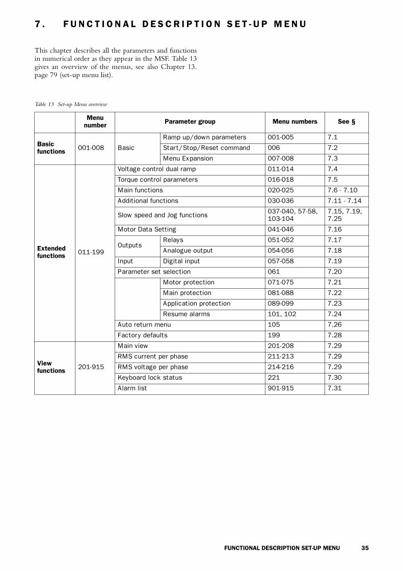
This chapter describes all the parameters and functionsin numerical order as they appear in the MSF. Table 13gives an overview of the menus, see also Chapter 13.page 79 (set-up menu list).
Table 13 Set-up Menu overview
Menu number Parameter group Menu numbers See §
Basic functions 001-008 Basic
Ramp up/down parameters 001-005 7.1
Start/Stop/Reset command 006 7.2
Menu Expansion 007-008 7.3
Extended functions 011-199
Voltage control dual ramp 011-014 7.4
Torque control parameters 016-018 7.5
Main functions 020-025 7.6 - 7.10
Additional functions 030-036 7.11 - 7.14
Slow speed and Jog functions 037-040, 57-58, 103-104
7.15, 7.19, 7.25
Motor Data Setting 041-046 7.16
OutputsRelays 051-052 7.17
Analogue output 054-056 7.18
Input Digital input 057-058 7.19
Parameter set selection 061 7.20
Motor protection 071-075 7.21
Main protection 081-088 7.22
Application protection 089-099 7.23
Resume alarms 101, 102 7.24
Auto return menu 105 7.26
Factory defaults 199 7.28
View functions 201-915
Main view 201-208 7.29
RMS current per phase 211-213 7.29
RMS voltage per phase 214-216 7.29
Keyboard lock status 221 7.30
Alarm list 901-915 7.31

36 FUNCTIONAL DESCRIPTION SET-UP MENU
7.1 Ramp up/down parameters
Fig. 32 Menu numbers for start/stop ramps, initial voltage at start and step down voltage at stop.
Determine the starting time for the motor/machine.When setting the ramp times for starting and stopping,initial voltage at start and step down voltage at stop,proceed as follow:
7.1.1 RMS current [005]
NOTE! This is the same read-out as function 201, see § 7.28, page 63.
Setting the initial voltage at start ramp 1
Default: 30%
Range: 25 - 90% Un
Set the initial voltage. Normally the factory setting, 30% of Un, is a suitable choice.
Setting of start ramp 1
Default: 10 sec
Range: 1-60 sec
Set ”Ramp up time” at start.
Setting of step down voltage stop ramp 1
Default: 100%
Range: 100-40% of Un
Step down voltage at stop can be used to stop smoothly.
UN Voltage
Time
0 0 1
3 0
0 0 2
1 0
0 0 3
0 01
Setting of stop ramp 1
Default: oFF
Range: oFF, 2-120 sec
oFF Stop ramp disabled
2-120 Set “Ramp down time” at stop
RMS current
Default: -------
Range: 0.0-9999Amp
Read-out of the RMS motor current.
0 0 4
F Fo
0 0 5
0. 0

FUNCTIONAL DESCRIPTION SET-UP MENU 37
7.2 Start/stop/reset commandStart/stop of the motor and reset of alarm is doneeither from the keyboard, through the remote controlinputs or through the serial interface (option). Theremote control inputs start/stop/reset (PCB terminals11, 12 and 13) can be connected for 2-wire or 3-wirecontrol.
NOTE! A reset via the keyboard will not start or stop the motor.
NOTE! Factory default setting is 2, remote control.
To start and stop from the keyboard, the “START/STOP” key is used.
To reset from the keyboard, the “ENTER /RESET” key is used. A reset can be given both whenthe motor is running and when the motor is stopped.A reset from the keyboard will not start or stop themotor.
7.2.1 2-wire start/stop with automatic reset at start
Closing PCB terminals 12 and 13, and a jumperbetween terminal 11 and 12, will give a start com-mand. Opening the terminals will give a stop. If PCBterminals 12 and 13 is closed at power up a start com-mand is given (automatic start at power up). When astart command is given there will automatically be areset.
7.2.2 2-wire start/stop with separate reset
Closing PCB terminals 11, 12 and 13 will give a startand opening the terminals 12 and 13 will give a stop. IfPCB terminals 12 and 13 are closed at power up a startcommand is given (automatic start at power up). WhenPCB terminals 11 and 13 are opened and closed again areset is given. A reset can be given both when themotor is running and stopped and doesn’t affect thestart/stop.
7.2.3 3-wire start/stop with automatic reset atstart.
PCB terminal 12 and 13 are normally closed and PCBterminal 11 and 13 are normally open. A start com-mand is given by momentarily closing PCB terminal11 and 13. To stop, PCB terminal 12 and 13 aremomentarily opened.
When a start command is given there will automat-ically be a reset. There will not be an automatic start atpower up.
Selection of control mode
Default: 2
Range: 1,2,3
1
START/STOP/RESET command via the keyboard.- Press the “START/STOP” key on the keyboard to start and stop the soft starter.
- Press “ENTER/RESET” key to reset a trip condition.
2
Via Remote control. START/STOP/RESET commands. The following control methods are possible:- 2-wire start/stop with automatic reset, see § 7.2.1, page 37.
- 2-wire start/stop with separate reset, see § 7.2.2, page 37.
- 3-wire start/stop with automatic reset at start, see § 7.2.3, page 37.
WARNING! The motor will start if terminals 11, 12, 13 is in start position.
3
START/STOP/RESET commands via serial interface option. Read the operating instruction supplied with this option.
0 0 6
2
Start/
Stop
Reset 1216
22
I U
J1J2
I U
11 13 14 15 17 18 19
21 23 24 31 32 33
1216
22
I U
J1J2
I U
11 13 14 15 17 18 19
21 23 24 31 32 33
Reset
Start/Stop
Start/Reset
Stop
1216
22
I U
J1J2
I U
11 13 14 15 17 18 19
21 23 24 31 32 33

38 FUNCTIONAL DESCRIPTION SET-UP MENU
7.3 Menu expansion setting.In order to use the viewing menus and/or theextended functions menu 007 must be set to “On”,then one reach read out of the viewing menus 201-915. To be able to set any extended functions in themenus 011-199 menu 008 must be set to “on” as well.
NOTE! Menu 007 must be “on”.
7.4 Voltage control dual rampTo achieve even smoother ramps at start and or stop, adual ramp can be used.
Fig. 33 Menu numbers for dual voltage ramp at start/stop, initial voltage at start and step down-voltage at stop.
The settings are carried out by beginning with the set-tings in menus 001-004 and 007-008 and proceed withthe following steps:
Selecting of extended functions and viewing functions
Default: oFF
Range: oFF, on
oFF Only function 1-7 are visible
on- View functions 201-915 are visible- Extended functions (menu 008) selectable
Selecting of extended functions
Default: oFF
Range: oFF, on
oFF Only view function 201-915 are visi-ble.
on All the function menus are visible
0 0 7
F Fo
0 0 8
F Fo
UN Voltage
Time
Setting the initial voltage at start ramp 2
Default: 90%
Range: 30-90% Un
Set the start voltage for start ramp 2. The initial voltage for start ramp 2 is limited to the initial volt-age at start (menu 001), see § 7.1, page 36.
Setting of start ramp 2
Default: oFF
Range: oFF, 1-60 sec
oFF Start ramp 2 disabled
1-60 Set the start ramp 2 time. A dual voltage ramp is active.
Setting of step down voltage in stop ramp 2
Default: 40%
Range: 100-40% Un
Set the step down voltage for stop ramp 2. The step down voltage for stop ramp 2 is limited to the step down voltage at stop (menu 003).
Setting of stop ramp time 2
Default: oFF
Range: oFF, 2-120 sec
oFF Stop ramp 2 disabled
1-60 Set the stop ramp 2 time. A dual voltage stop ramp is active.
0 1 1
9 0
0 1 2
F Fo
0 1 3
4 0
0 1 4
F Fo

FUNCTIONAL DESCRIPTION SET-UP MENU 39
7.5 Torque control parametersSee also § 7.10, page 42 and chapter 4. page 13 formore information on the Torque control setting.
7.6 Current limit (Main Function)The Current Limit function is used to limit the currentdrawn when starting (150 - 500% of In). This meansthat current limit is only achieved during set start-uptime.
Two kinds of current limit starts are available.• Voltage ramp with a limited current.
If current is below set current limit, this start will act exactly as a voltage ramp start.
• Current limit start. The soft starter will control the current up to set current limit immediately at start, and keep it there until the start is completed or the set start-up time expires.
See Fig. 34 Current limit.
NOTE! Make sure that nominal motor current in menu 042 is correctly inserted.
7.6.1 Voltage ramp with current limitThe settings are carried out in three steps:1. Estimate starting-time for the motor/machine and
select that time in menu 002 (see § 7.1, page 36).2. Estimate the initial voltage and select this voltage in
menu 001 (see § 7.1, page 36).3. Set the current limit to a suitable value e.g. 300% of
In in menu 020.
NOTE! Only possible when Voltage Ramp mode is enabled. Menus 021-025 must be “oFF”.
Fig. 34 Current limit
Initial torque at start
Default: 10
Range: 0 - 250% of Tn
Insert initial torque at start in percent of nominal shaft torque (Tn), see chapter 13. page 79.
End torque at start
Default: 150
Range: 50 - 250% of Tn
Insert end torque at start in percent of nominal shaft torque.
End torque at stop
Default: 0
Range: 0 - 100% of Tn
Insert end torque at stop in percent of the nominal motor torque.
0 1 6
1 0
0 1 7
5 01
0 1 8
0
Voltage ramp with current limit at start
Default: oFF
Range: oFF, 150 - 500% In
oFFVoltage Ramp mode with current limit disabled. Voltage Ramp ena-bled.
150-500 Current limit level in Voltage ramp mode.
0 2 0
F Fo
03-F109
Time
Current
Currentlimit atstart
Voltage ramp

40 FUNCTIONAL DESCRIPTION SET-UP MENU
7.6.2 Current limitThe settings are carried out in two steps:1. Estimate starting time for the motor/machine and
select that time in menu 002 (see § 7.1, page 36).2. Set the current limit to a suitable value e.g. 300% of
In in menu 021.
NOTE! Only possible when Voltage Ramp mode is enabled. Menus 020, 022-025 must be “oFF”.
NOTE! Even though the current limit can be set as low as 150% of the nominal motor current value, this minimum value cannot be used generally. Considerations must be given to the starting torque and the motor before setting the appropriate current limit. "Real start time" can be longer or shorter than the set values depending on the load conditions. This applies to both current limit methods.
Fig. 35 Current limit
If the starting time is exceeded and the soft starter isstill operating at current level, an alarm will be acti-vated. It is possible to let the soft starter to either stopoperation or to continue. Note that the current willrise uncontrolled if the operation continues (see §7.24.2, page 61).
7.7 Pump control (Main Function)By choosing pump control you will automatically get astop ramp set to 15 sec. The optimising parameters forthis main function are start and stop time; initial torqueat start and end torque at start and stop. End torque atstop is used to let go of the pump when it´s no longerproducing pressure/flow, which can vary on differentpumps. See Fig. 36.
Fig. 36 Pump control
Pump applicationThe pump application is using Torque ramps for quad-ratic load. This gives lowest possible current and linearstart and stop ramps. Related menus are 2, 4 (see § 7.1,page 36), 16, 17 and 18 (see § 7.5, page 39).
NOTE! Only possible when Voltage Ramp mode is enabled.Menu 020-021, 023-025 must be “oFF”.
Current limit at start
Default: oFF
Range: oFF, 150 - 500% In
oFF Current limit mode disabled. Voltage Ramp enabled.
150-500 Current limit level in current limit mode.
0 2 1
F Fo
03-F110
FLC
Current
Starting time
CurrentLimit
Time
Setting of pump control
Default: oFF
Range: oFF, on
oFF Pump control disabled. Voltage Ramp enabled.
on Pump control application is enabled.
03-F118
FLC
Current (A)
TimeSpeed
Time
0 2 2
F Fo

FUNCTIONAL DESCRIPTION SET-UP MENU 41
7.8 Analogue Input Control (Main Function)
Soft starting and soft stopping can also be controlled viathe Analogue Input Control (0-10 V, 2-10 V, 0-20 mAand 4-20 mA). This control makes it possible to con-nect optional ramp generators or regulators.
After the start command, the motor voltage is con-trolled through the remote analogue input.
WARNING! The remote analogue control may not be used for continuous speed regulation of stand-ard motors. With this type of operation the in-crease in the temperature of the motor must be taken into consideration.
To install the analogue input control, proceed by:1. Connect the ramp generator or regulator to termi-
nal 14 (+) and 15 (—).
Fig. 37 Wiring for analogue input.
2. Set Jumper J1 on the PCB control card to voltage(U) or current control (I) signal position, see Fig. 38and Fig. 24 on page 28. Factory setting is voltage(U).
Fig. 38 Setting voltage or current for analogue input.
NOTE! Only possible when Voltage Ramp mode is enabled. Menu 020-022, 024, 025 must be “oFF”
7.9 Full voltage start, D.O.L. (Main Function)
The motor can be accelerated as if it was connecteddirectly to the mains. For this type of operation:
Check whether the motor can accelerate therequired load (D.O.L.-start, Direct On Line start). Thisfunction can be used even with shorted thyristors.
NOTE! Only possible when Voltage Ramp mode is enabled.Menu 020-023, 025 must be “oFF”.
Fig. 39 Full voltage start.
Selection of Analogue input control
Default: oFF
Range: oFF, 1, 2
oFF Analogue input disabled. Voltage Ramp enabled.
1 Analogue input is set for 0-10V/0-20mA control signal
2 Analogue input is set for 2-10V/4-20mA control signal.
!
1216
22
I U
J1J2
I U
11 13 14 15 17 18 19
21 23 24 31 32 33
03-F53
1216
22
I U
J1J2
I U
11 13 14 15 17 18 19
21 23 24 31 32 33
0 2 3
F Fo
Setting of D.O.L start
Default: oFF
Range: oFF, on
oFF D.O.L. start disabled. Voltage Ramp enabled.
on D.O.L. start enabled
0 2 4
F Fo
03-F115
FLC
6-7xInom
Time

42 FUNCTIONAL DESCRIPTION SET-UP MENU
7.10 Torque control (Main function)This main function can be used to make a start accord-ing to a pre-defined torque reference curve. Two dif-ferent load characteristics, linear and square, arepossible to select.
At start/stop the torque controller will follow theselected characteristic.
A torque start/stop behaviour can be seen in Fig.40.
A perfect start and stop with torque ramps have agood linearity of current. To optimise this, use the set-ting of initial torque (menu 16) and end torque (menu18). See also § 7.5, page 39.
Example:Default for initial torque is 10% so if starting a more heavy load this will result in a small current peak in beginning of ramp. By increasing this value to 30/70% the current peak will not appear.
The end torque is increased mainly if the applica-tion has a high inertial load, like planers, saws and centrifuges. A current peak will appear in the end of ramp because the load is pushing the speed more or less by itself. By increasing this level to 150-250% the current will be linear and low.
NOTE! Torque control mode is only possible when Voltage Ramp mode is enabled (menu 020-024 are “oFF”).
Fig. 40 Torque control at start/stop.
Fig. 41 Current and speed in torque control.
Torque control at start/stop
Default: oFF
Range: oFF, 1, 2
oFF Torque control is disabled Voltage Ramp enabled.
1 Torque control with linear torque characteristic
2 Torque control with square torque characteristic
0 2 5
F Fo
03-F37
12 2
1
Torque
2 Tn
1.5 Tn
0.5 TnInitial torque
1 Linear
2 Square
Start time Stop time Time
End torque
Tn
End torque at stop
Nominal Torque
2.5 Tn
03-F113
FLC
03-F114
Current (A)
Time
Speed
Time

FUNCTIONAL DESCRIPTION SET-UP MENU 43
7.11 Torque boostThe Torque Booster enables a high torque to beobtained by providing a high current during 0.1 - 2 secat start. This enables a soft start of the motor even if thebreak away torque is high at start. For example incrushing mills applications etc.
When the torque booster function has finished,starting continues according to the selected start mode.
Fig. 42 The principle of the Torque Booster when starting the motor in voltage ramp mode.
See § 4.6, page 19, which main function that can beused with the torque boost.
NOTE! Check whether the motor can accelerate the load with "Torque booster", without any harmful mechanical stress.
7.12 BypassIn cases of high ambient temperatures or other reason itmay sometimes be necessary to use a by-pass contactorto minimize the power loss at nominal speed (see Tech-nical Data). By using the built-in Full Voltage Relayfunction an external contactor can be used to Bypassthe soft starter when operating at nominal speed.
Bypass contactor can also be used if soft stop isrequired. Normally a Bypass contactor is not necessaryas the device is designed for continues running condi-tions, see Fig. 29 on page 33 for wiring example.
NOTE! If one like to use the alarm functions, the extended functions or the viewing functions the 2-pcs current transformers must be mounted outside the soft start as shown in Fig. 44 and Fig. 45 on page 45. For this purpose an optional extension cable for the current transformers is available. Code No 01-2020-00.
CAUTION! If the current transformers are not mounted as in Fig. 43 on page 44 and § 6.2, page 28, the alarm and viewing functions will not work. Do not forget to set menu 032 to ON, otherwise there will be an F12 alarm and at the stop command will be a freewheeling stop.
For further information see chapter 6.2 page 28.
Torque boost active time
Default: oFF
Range: oFF, 0.1 - 2 sec
oFF Torque boost disabled
0.1-2.0 Set the Torque boost time.
Torque boost current limit
Default: 300
Range: 300 - 700% of In
The Torque boost current controller use selected value as the motor current reference.
03-F40Time
Torque boost Current limit
Full speed Load current
0 3 0
F Fo
0 3 1
0 03
Setting of Bypass
Default: oFF
Range: oFF, on
oFF Bypass disabled
on
Bypass enabled. Program either relay K1 or K2 to function 2 to control the bypass con-tactor, see menu 51/52.
0 3 2
F Fo
!

44 FUNCTIONAL DESCRIPTION SET-UP MENU
Fig. 43 Bypass wiring example MSF 310-1400.
03-F19
L1
L2
L3
N
Q2
3121 22 23 24 33K1 K2 K3L1 L2 L3 PE 01 02 PE
13
start0
1
/stop
PET2T1 T3 11 12 1514 16 17 18 19
32 69 70
7775 76
PE
M3 ~
PE
U V W
T1 T2 T3 PE
Current transformer position and connection
For MSF-017 to MSF-250, see Fig. 44.
For MSF-310 to MSF-1400, see Fig. 45.

FUNCTIONAL DESCRIPTION SET-UP MENU 45
Fig. 44 Current transformer position when Bypass MSF-017 to MSF-250.
Fig. 45 Current transformer position when Bypass MSF-310 to MSF-1400.
T1 T2 T3
U V W
03-F56
P1
P2
P1
P2
SOFTSTARTER
MOTOR
Blue to
Brown to
Blue to
Brown to
terminal 75
terminal 77
terminal 76
terminal 77
T1 T2 T3
U V W
03-F57
P1
P2
P1
P2
SOFTSTARTER
MOTOR
Blue to
Brown to
Blue to
Brown toterminal 77
terminal 75terminal 76
terminal 77

46 FUNCTIONAL DESCRIPTION SET-UP MENU
7.13 Power Factor ControlDuring operation, the soft starter continuously moni-tors the load on the motor. Particularly when idling orwhen only partially loaded, it is sometimes desirable toimprove the power factor. If Power factor control(PFC) is selected, the soft starter reduces the motorvoltage when the load is lower. Power consumption isreduced and the degree of efficiency improved.
NOTE! If the PFC is used the EMC-directive is not fulfilled.
7.14 Brake functionsThere are two built in braking methods for applicationswere the normal stop ramp is not enough. • Dynamic DC-brake
Increases the braking torque by decreasing speed.• Soft brake
Gives a high torque at the start of the braking and then also increasing torque by decreasing speed.
In both methods the MSF detects when the motor isstanding still, so rotating in wrong direction is avoided.
Dynamic Vector Brake• Possible to stop motors with high inertia loads from
close to synchronous speed.• At 70% of the nominal speed a DC-brake is acti-
vated until the motor is standing still or the selectedBraking Time has expired (see menu 34, nextpage).
• No contactor needed.• For extra safety, the soft starter has a digital input
signal for monitoring standstill so that at real motorstandstill will stop the output voltage immediately(see § 7.19, page 53).
Soft brake• Even very high inertia loads can be stopped• The Soft brake is a controlled reversing of the
motor as the MSF measures the speed during brak-ing.
• Two contactors are needed which can be placed onthe in- or output of the soft starter. On the inputthe first contactor is connected to relay K1 which isalso used as a mains contactor.
• At 30% of the nominal speed a DC-brake is acti-vated until the motor is standing still or the selectedBraking Time has expired (menu 34, next page).
• For extra safety, the soft starter has a digital inputsignal for monitoring standstill. So that the outputvoltage is stopped immediately (see menu 57-58, §7.19, page 53).
See Fig. 47 on page 47 for the following set-upsequence:• Soft brake is activated if menu 36=2 and menu 34
has a time selected (see next page). • Menu 51 and 52 are automatically set to 5 and 4 to
get the correct relay functions on K1 and K2 (see §7.17, page 51).
• Relay K1 should be used to connect a contactor forsupply L1, L2, L3 to MSF or motor.
• Relay K2 is used to connect phase shifting contac-tor to change L1, L2 and L3 to MSF or motor.
• At start K1 is activated and connects L1, L2, L3then the motor starts. At stop K1 opens and discon-nects L1, L2, and L3 and after 1s K2 connects withthe other phase sequence and the braking of themotor is active.
NOTE! Soft brake uses both programmable relays. For other functions, see also the function table in chapter 7. page 35.
NOTE! For several start/stops it is recommend to use the PTC input.
WARNING! If the Soft Brake function has been selected once and after that the Bypass function is selected, then the relay functions on K1 and K2 remain in the Soft Brake functionality. Therefore it
is necessary to change the relay functions in menu 51-52 manually to the Bypass functions (see § 7.17, page 51) or reset to default in menu 199 (see § 7.28, page 63) and select the Bypass function again.
Fig. 46 Braking time
Setting of PFC
Default: oFF
Range: oFF, on
oFF PFC disabled
on PFC enabled. The Full voltage relay function does not work.
0 3 3
F Fo
Braking time
Default: oFF
Range: oFF, 1 - 120 sec
oFF Brake function disabled
1-120 Brake time
!
0 3 4
F Fo
03-F121
Softbrake
Dynamic DC
Torque
Nom. speed0-speed

FUNCTIONAL DESCRIPTION SET-UP MENU 47
Fig. 47 Soft brake wiring example.
Braking Strength
Default: 100
Range: 100 - 500%
Brake method
Default: 1
Range: 1, 2
1 Dynamic vector brake, active
2 Soft brake active
0 3 5
0 01
0 3 6
1
L1
L2
L3
N
3121 22 23 24 33K1 K2 K3L1 L2 L3 PE 01 02 PE
13
start/stop
PET2T1 T3 11
1
0
12 1514 16 17 18 19
32 69 70
7775 76
PE
U V W PE
Q2(rev)
Q1(fwd)
M3 ~
03-F106

48 FUNCTIONAL DESCRIPTION SET-UP MENU
7.15 Slow speed and Jog functionsThe soft starter is able to run the motor at a fixed slowspeed for a limited period of time.
The slow speed will be about 14% of the full speedin the forward direction and 9% in the reverse direc-tion.
The following functions are possible:• Slow speed controlled by an external signal.
The digital input is used to run at slow speed at a start or stop command for a selected number of pulses (edges) generated by an external sensor (photo cell, micro switch, etc.). See § 7.19, page 53 for more instructions.
• Slow Speed during a selected time period.The slow speed will be active after a stop command for a selected time period. See § 7.19, page 53 for more instructions.
• Slow Speed using the "JOG"-commands.The slow Speed can be activated via the JOG keys on the keyboard or externally via the analogue input. See § 7.25, page 61 for more instructions.
7.15.1 Slow speed controlled by an external signal.
With these setting it is possible to have an externalpulse or edge signal controlling the time that the SlowSpeed is active either after a Start command or a Stopcommand or at both commands. The following menu’sare involved:
Installation is as follows:1. Set the analogue input selection for Slow Speed
operation. Menu 57=2. See § 7.19, page 53. SeeFig. 37 on page 41 for a wiring example.
2. Select in menu 38 (see § 7.15.2, page 49) the SlowSpeed at Start time. This time will now be the abso-lute maximum time for Slow Speed to be activeafter a start command, in case the external signalwill not appear.
3. Select in menu 39 (see § 7.15.2, page 49) the SlowSpeed at Stop time. This time will now be the abso-lute maximum time for Slow Speed to be activeafter a stop command, in case the external signalwill not appear.
4. Select in menu 57 (see § 7.19, page 53) the numberof edges to be ignored by the Slow Speed input,before a start or stop is executed at slow speed. Theedges are generated by an external sensor (photocell, micro switch, etc.).
The Slow Speed torque (menu 37) and DC-Brake afterSlow Speed (menu 40) can be selected if needed. (see § 7.15.4, page 49).
When the number of edges exceeds or the time expire,a start according to selected main function is made.
At stop, the motor will ramp down (if selected) andDC brake (if selected) before a slow speed forward atstop will begin. Slow speed will last as long as thenumber of edges on the external input is below param-eter value in menu 036 and the max duration timedoesn’t expires. When the number of edges exceeds orthe time expire, a stop is made.
In Fig. 48 on page 48 the selected number of edgesare 4. It is recommended to select DC-brake (se § 7.14,page 46) before a slow speed at stop if it is a high inertiaload. See Fig. 29 on page 33 for wiring diagram. Incase one use DC-brake, see § 7.15.4, page 49.
Fig. 48 Slow speed controlled by an external signal.
This additional function can be used together withmost of the main functions (see § 4.6, page 19).
Menu Function See page
57 Digital input selection page 53
58 Pulse selection page 53
37 Slow speed torque page 49
38 Slow speed time at start page 49
39 Slow speed time at stop page 49
40 DC-Brake at slow speed page 49
Slow speed torque
Default: 10
Range: 10-100
Select the magnitude of the slow speed torque.
03-F44
Speed
nN
0.14*nN
Start command
Open
Closed
Time when signal is ignored
Slowspeedat start
Ramp timeat start
Full voltagerunning
Ramp timeat stop including DC-brake
Slow speedat stop
Stopped
Time
time
Externalsignal
0 3 7
1 0

FUNCTIONAL DESCRIPTION SET-UP MENU 49
7.15.2 Slow speed during a selected time It is possible to have a slow speed in forward directionbefore a start and after a stop. The duration of the slowspeed is selectable in menus 038 and 039.
It is recommended to select DC brake (see § 7.14,page 46) before a slow speed at stop if it is a high inertiaload. This slow speed function is possible in all controlmodes, keyboard, remote and serial communication.
Fig. 49 Slow speed at start/stop during a selected time.
The Slow speed torque (menu 37) and the DC-Brakeafter Slow speed (menu 40, § 7.15.4, page 49) can beselected if needed.
7.15.3 Jog FunctionsThe Jog commands can be used to let the motor run ata Slow speed (forward or reverse) as long as the Jogcommand is active.
The Jog commands can be activated in 2 differentways:• Jog keys
The Jog-Forward and Jog-reverse keys on the con-trol panel. The keys can be programmed separate for each function. See § 7.25, page 61 for more instructions
• External Jog commandThe external command is given via terminal 14 at the digital input. Only 1 function (forward or reverse) can be programmed to the digital input at the time. See § 7.19, page 53 for more instructions.
7.15.4 DC-brake after slow speed at stop [040]A DC-brake after a slow speed at stop is possible tohave, i.e. for a high inertia load or for a precise stop.
The current is controlled and the reference valuefor the normal DC-brake function is used (see § 7.15.4, page 49).The duration for the DC-brake is possible to select.
This DC-brake function is not applied when the“JOG “ and “JOG “ keys are used.
Slow speed time at start
Default: oFF
Range: oFF, 1 - 60 sec
oFF Slow speed at start is disabled
1-60 Set slow speed time at start.
Slow speed time at stop
Default: oFF
Range: oFF, 1 - 60 sec
oFF Slow speed at stop is disabled
1-60 Set slow speed time at stop.
0 3 8
o F F
o F F
0 3 9
03-F41
Speed
nN
0.14
Time
*nNRamp time atstart
Start command StoppedStop command
Ramp time at stop in-cluding DC-brake time
Slow speed at stop
Full voltage running
Slow speed at start
Slow speed
Nominal speed
DC-Brake at slow speed
Default: oFF
Range: oFF, 1-60
oFF DC-brake after slow speed at stop disabled.
1-60 DC-brake duration time after slow speed at stop.
JOG JOG
0 4 0
o F F

50 FUNCTIONAL DESCRIPTION SET-UP MENU
7.16 Motor data settingThe first step in the settings is to set menu 007 and 008to “on” to be able to reach the menus 041-046 andenter the motor data.
NOTE! The default factory settings are for a standard 4-pole motor acc. to the nominal current and power of the soft starter. The soft starter will run even if no specific motor data is selected, but the performance will not be optimal.
NOTE! Now go back to menu 007, 008 and set it to “oFF”and then to menu 001.
Nominal motor voltage
Default: 400 V
Range: 200-700 V
Make sure the soft starters maximum voltage rat-ing is suitable for chosen motor voltage.
Nominal motor current
Default: Nominal soft starter current
Range: 25% - 150% of Insoft in Amp.
Nominal motor power
Default: Nominal soft starter power
Range: 25% - 300% of Pnsoft in kW
Nominal motor speed
Default: Nnsoft in rpm
Range: 500-3600 rpm
0 4 1
0 04
0 4 2
1 7
0 4 3
7. 5
0 4 4
5 041
Nominal motor cos phi
Default: 0.86
Range: 0.50-1.00
Nominal frequency
Default: 50 Hz
Range: 50/60 Hz
0 4 5
8 60.
0 4 6
5 0

FUNCTIONAL DESCRIPTION SET-UP MENU 51
7.17 Programmable relay K1 and K2The soft starter has three built-in auxiliary relays, K3(change over contacts), is always used as an alarm relay.The other two relays, K1 and K2 (closing contacts), areprogrammable.
K1 and K2 can be set to either “Operation”, “FullVoltage” or “Pre-alarm” indication. If DC-brake ischosen the relay K2 will be dedicated to this function.
Fig. 50 Start/stop sequence and relay function “Operation” and “Full voltage”.
WARNING! If the Soft Brake function has been selected once and after that the Bypass function is selected, then the relay functions on K1 and K2 remain in the Soft Brake functionality. Therefore it is necessary to change the relay functions in menu 51-52 manually to the Bypass functions (see § 7.12, page 43) or reset to default in menu 199 (see § 7.28, page 63) and select the Bypass function again.
Setting of K1 indication
Default: 1
Range: 1, 2, 3, 4, 5
1 K1 is set for “Operation”
2 K1 is set for “Full Voltage”
3 K1 is set for “Power pre-alarm”
4 No function
5 K1 is set for “Run”
Motorvoltage U
N
Run
FunctionOperation
FunctionFull voltage
Startdelay0,1 sec.
Startingtime
Fullvoltage
Stoppingtime
Time
Time
Time
Time
0 5 1
1
Setting of K2 indication
Default: 2
Range: 1, 2, 3, 4, 5
1 K2 is set for “Operation”
2 K2 is set for “Full Voltage”
3 K2 is set for “Power pre-alarm”
4 K2 is set for “Softbrake”
5 K2 is set for “Run”
0 5 2
2
!

52 FUNCTIONAL DESCRIPTION SET-UP MENU
7.18 Analogue outputThe soft starter can present current, voltage and poweron an analogue output terminal, for connection to arecording instrument or a PLC. The output can beconfigured in 4 different ways, 0-10V, 2-10V, 0-20mA or 4-20 mA. To install the instrumentproceed as follows:
1. Connect the instrument to terminal 19 (+) and 15 (-).
Fig. 51 Wiring for analogue output.
2. Set Jumper J2 on the PCB board to voltage (U) orcurrent (I) signal position. Factory setting is voltage(U). See Fig. 52 on page 52 and Fig. 24 on page 28.
Fig. 52 Setting of current or voltage output.
3. Set the parameter in menu 054.
4. Choose a read-out value in menu 055
5. Set analogue output gain to adjust the range of cho-sen analogue output value in menu 056.
Example on settings:
Analogue output
Default: oFF
Range: oFF, 1, 2
oFF Analogue ouput is disabled
1 Analogue output is set to 0-10V/0-20mA
2 Analogue output is set to 0-10V/4-20mA
PCB terminal
03-F53
1216
22
I U
J1J2
I U
11 13 14 15 17 18 19
21 23 24 31 32 33
1216
22
I U
J1J2
I U
11 13 14 15 17 18 19
21 23 24 3
0 5 4
Fo F
Analogue output value
Default: 1
Range: 1, 2, 3
1 RMS current, default range 0-5xIn
2 Line input RMS voltage, default range 0-720V
3 Output shaft power, default range 0-2xPn
Analogue output gain
Default: 100%
Range: 5-150%
Set value Iscale Uscale Pscale
100% 0-5xIn 0-720V 0-2xPn
50% 0-2.5xIn 0-360V 0-Pn
0 5 5
1
0 5 6
1 0 0

FUNCTIONAL DESCRIPTION SET-UP MENU 53
7.19 Digital input selectionThe analogue input can be used as a digital input. Thisis programmed in Menu 57. There are 4 different func-tions:• Rotation sensor input for braking functions. See
§ 7.14, page 46.• Slow speed external controlled. See § 7.15.1, page
48.• Jog functions forward or reverse enabled. See §
7.25, page 61.
Fig. 53 shows how to set the input for voltage or cur-rent control, with jumper J1 the control board. Thedefault setting for J1 is voltage control.
Fig. 53 Setting of J1 for current or voltage control.
Fig. 54 shows a wiring example for the analogue inputas it is used for digital input.
Fig. 54 Wiring for slow speed external input.
NOTE! If the Main Function Analogue control is program-med (see § 7.8, page 41) the analogue input can not be used for digital signal input. The menu 57 is then automatically set to OFF.
NOTE! Jog forward, reverse has to be enabled, see § 7.25, page 61.
Depending on the selection made in menu 57, menu58 is used to program the number of the edges. Theedges can be generated by an external sensor (photocell, micro switch etc.).
Digital input selection
Default: oFF
Range: oFF, 1-4
oFF No digital input control
1 Rotation sensor for brake functions
2 Slow speed function
3 Jog forward command
4 Jog reverse command
1216
22
I U
J1J2
I U
11 13 14 15 17 18 19
21 23 24 31 32 33
OpenClosed
1216
22
I U
J1J2
I U
11 13 14 15 17 18 19
21 23 24 31 32 33
0 5 7
Fo F
Digital input pulses
Default: 1
Range: 1-100
If Menu 57=1.A positive or negative edge at analogue input from a rotation sensor will give a signal to stop the braking voltage.If Menu 57=2The number of edges to be ignored by the slow speed input, before a start or stop is executed at slow speed.
0 5 8
1

54 FUNCTIONAL DESCRIPTION SET-UP MENU
7.20 Parameter SetParameter Set, an important function which can behandy when using one soft starter to switch in and startdifferent motors, or working under variable load con-ditions. For example; starting and stopping conveyorbelts with different weight on the goods from time totime.
For sets of parameters can be controlled either fromthe keyboard, the external control inputs or the serialinterface (option). Up to 51 different parameters can beset for each Parameter Set.
Fig. 55 Parameter overview
When ’Parameter set’ in menu 061 is set to 0 (externalselection), only parameters in menu 006 (Controlmode) and 061 (Parameter set) can be changed. Allother parameters are not allowed to change.
It is possible to change parameter set at stop and atfull voltage running.
Fig. 56 Connection of external control inputs.
Parameter Set 1
Common for all parameter set
007, 008, 046, 051, 052, 061, 071, 072,088, 089, 105, 111, 112, 113, 114, 199,206
001, 002, 003, 004, 006,011, 012, 013, 014, 016,017, 020, 021, 022, 023,024, 025, 030, 031, 032,033, 034, 035, 036, 037,038, 039, 040, 041, 042,043, 044, 045, 055, 056,057, 058, 074, 075, 081,082, 083, 084, 085, 086,091, 092, 093, 094, 095,096, 097, 098, 099, 101,102, 103, 104
Parameter Set 2
Parameter Set 3
Parameter Set 4
Parameter set
Default: 1
Range: 0, 1, 2, 3, 4
0Parameter set are selected by the external input 16 and 17 (see below).
1, 2, 3, 4 Selection of parameter set 1-4.
Parameter Set PS1 (16-18) PS2 (17-18)
1234
OpenClosedOpen
Closed
OpenOpen
ClosedClosed
0 6 1
1
03-F53
1216
22
I U
J1J2
I U
11 13 14 15 17 18 19
21 23 24 31 32 33

FUNCTIONAL DESCRIPTION SET-UP MENU 55
7.21 Motor protection, overload (F2 alarm)
In many cases it is convenient to have a completestarter. The soft starter have a possibility to use eitheran input PTC signal from the motor, an internal ther-mal model of the motor for thermal protection or bothtogether at the same time. Slight overload for long timeand several overloads of short duration will be detectedwith both methods.
NOTE! Open terminals will give an F2 alarm immediately. Make sure the PTC is always connected or the terminals are shorted.
NOTE! The internal motor thermal protection will still generate an alarm if it is not selected oFF.
NOTE! If ’Bypass’ is used check that the current trans-formers are placed and connected correctly (see Fig. 43 on page 44).
CAUTION! Used thermal capacity is set to 0 if the control board loses its supply (terminal 01 and 02). This means that the internal thermal model starts with a ’cold’ motor, which perhaps in reality is not the case. This means that the motor can be overheated.
Fig. 57 The thermal curve
Motor PTC input
Default: no
Range: no, YES
no Motor PTC input is disabled
YES
Motor PTC input is activated:- Connect the PTC to terminals 69 and 70, see table 12, page 32 and § Fig. 30, page 34.
- A to hot motor will give an F2 alarm. The alarm can only be reset-ted after cooling down of the motor.
0 7 1
n o
Internal motor thermal protection
Default: 10
Range: oFF, 2-40 sec
oFF Internal motor protection is disabled.
2-40
Selection of the thermal curve according to Fig. 57- Check that menu 042 is set to the proper motor current (see § 7.16, page 50).
- If the current exceeds the 100% level an F2 alarm is activated.
- The motor model thermal capacity must cool down to 95% before reset can be accepted.
- Used thermal capacity in menu 073 in § 7.21, page 55.
0 7 2
01
!
Overload time sec
Current (x Inom)

56 FUNCTIONAL DESCRIPTION SET-UP MENU
7.22 Mains protection
Used thermal capacity
Default: -
Range: 0-150%
Read-out of the used thermal capacity. If menu 072 ’Internal motor thermal protection’ is selected oFF, the capacity is shown as if the default class 10 was selected.
Starts per hour limitation
Default: oFF
Range: oFF, 1-99/hour
oFF Starts per hour limitation is disabled.
1-99Sets the start per hour limitation alarm. If the selected number is exceeded, alarm F11 occurs.
Locked rotor alarm
Default: oFF
Range: oFF, 1.0-10.0 sec
oFF Locked rotor alarm is disabled
1.0-10.0An F5 alarm is given when the rotor locks. The alarm is active during starting and running.
0 7 3
0
0 7 4
FFo
0 7 5
FFo
Voltage unbalance alarm
Default: 10
Range: 2 -25% Un
Insert limit in % of nominal motor voltage. Max unbalance in voltage between the 3 input phases is compared with the selected value. This is a cate-gory 2 alarm.
Response delay voltage unbalance alarm
Default: oFF
Range: oFF, 1-60 sec
oFF Unbalance voltage alarm is disabled
1-60 Set the response delay time for unbalanced voltage alarm F8.
Over voltage alarm
Default: 115
Range: 100 -150% Un
Insert limit in % of nominal motor voltage. Max volt-age of the 3 input phases is compared with the selected value. This is a category 2 alarm.
Response delay over voltage alarm
Default: oFF
Range: oFF, 1-60 sec
oFF Overvoltage alarm is disabled
1-60 Set the response delay time for over voltage alarm F9.
0 8 1
01
0 8 2
FFo
0 8 3
511
0 8 4
o F F

FUNCTIONAL DESCRIPTION SET-UP MENU 57
NOTE! The actual phase sequence can be viewed in menu 87.
7.23 Application protection (load monitor)
7.23.1 Load monitor max and min/protection (F6 and F7 alarms)
MSF has a built in load monitor based on the outputshaftpower. This is a unique and important functionwhich enables protection of machines and processesdriven by the motor connected to the soft starter. Botha Min and Max limit is possible to select.
In combination with the pre-alarm function, see § 7.23.2, page 58, this create a powerful protection. Anauto set function is also included for an automatic set-ting of the alarm limits. A start-up delay time can beselected to avoid undesired alarms at start-up, see Fig.58 on page 60.
NOTE! The load monitor alarms are all disabled during a stop ramp.
NOTE! System must be in full voltage running before an auto set is permitted.
The actual power is regarded as 1.00xPact.The set levels are:
Power max alarm limit[092]: 1.15xP actual Power max pre-alarm limit[094]: 1.10xP actual Power min pre-alarm limit[096]: 0.90xP actual Power min alarm limit[098]: 0.85xP actual
A successful auto set shows a message ’Set’ for 3 s and ifsomething goes wrong a message ’no’ will be showed.
Under voltage alarm
Default: 85
Range: 75-100 Un
Insert limit in % of nominal motor voltage. Min volt-age of the 3 input phases is compared with the selected value. This is a category 2 alarm.
Response delay under voltage alarm
Default: oFF
Range: oFF, 1-60 sec
oFF Under voltage alarm is disabled
1-60 Set the response delay time for under voltage alarm F10
Phase sequence
Default: -
Range: L123, L321
L123 is the direct phase sequence.L321 is the reverse phase sequence.
Phase reversal alarm
Default: oFF
Range: oFF, on
oFF Phase reversal alarm is disabled
on
Sets the phase reversal Alarm.- Switch on the power supply first. The phase sequence is stored as the correct sequence.
- Sets the menu 088 to “on”.- Any reversal of phase sequence will cause alarm F16.
0 8 5
FFo
0 8 6
FFo
0 8 7
- - - -
0 8 8
F Fo
Auto set power limits
Default: no
Range: no, YES
no Auto set is disabled
YES Auto set is activated if ENTER is pressed.
Output shaftpower in %
Default: -
Range: 0-200%
Measured output shaftpower in % of nominal motor power.
0 8 9
on
0 9 0
0

58 FUNCTIONAL DESCRIPTION SET-UP MENU
7.23.2 Pre-alarmIt could be useful to know if the load is changingtowards a load alarm limit. It is possible to insert both aMax and Min pre-alarm limit based on the motor out-put shaft power. If the load exceeds one of these limits,a pre-alarm condition occurs.
It should be noted that it is not normal alarms.They will not be inserted in the alarm list, not activat-ing the alarm relay output, not displayed on the displayand they will not stop operation. But it is possible toactivate relay K1 or K2 if a pre-alarm condition occurs.To have pre-alarm status on any of these relays, selectvalue 3 in menu 051 or 052 (see § 7.17, page 51).
A start-up delay time can be selected in menu 091to avoid undesired pre-alarms at start-up. Note that thistime is also shared with power Max and Min alarms.
NOTE! The pre-alarm status is always available on the serial communication.
Start delay power limits
Default: 10 sec
Range: 1-250 sec
From start command during selected delay time, all power load monitor alarms and pre-alarms are disa-bled.
Max power alarm limit
Default: 115
Range: 5-200% Pn
Insert limit in % of nominal motor power. The actual power in % of nominal motor power, could be read out in menu 090. If output shaft power exceeds selected limit, an F6-alarm occurs after the response delay time. The ’Auto set’ function in menu 089, affect this limit even if the alarm is set "oFF" in menu 093. This is a category 1 alarm.
Response delay max alarm
Default: oFF
Range: oFF, 0.1-25.0 sec
oFF Max Alarm is disabled.
0.1-25.0 Sets the response delay of the Max Alarm level.
0 9 1
1 0
0 9 2
1 1 5
0 9 3
o F F
Max power pre-alarm limit
Default: 110
Range: 5 -200% Pn
Insert limit in % of nominal motor power. The actual power in % of nominal motor power, could be read out in menu 090. If output shaft power exceeds selected limit, a pre-alarm occurs after the respon-se delay time. The ’Auto set’ function in menu 089, affect selected limit even if the pre-alarm is set "oFF" in menu 095.
Max pre-alarm response delay
Default: oFF
Range: oFF, 0.1 - 25.0 sec
oFF Max Pre-Alarm is disabled.
0.1-25.0 Sets the response delay of the Max Pre-Alarm level.
0 9 4
011
0 9 5
FFo

FUNCTIONAL DESCRIPTION SET-UP MENU 59
Min power pre-alarm limit
Default: 90%
Range: 5 -200% Pn
Insert limit in % of nominal motor power. The actual power in % of nominal motor power, could be read out in menu 090. If output shaft power goes below selected limit, a pre-alarm occurs after the response delay time. The ’Auto set’ function in menu 089, affect selected limit even if the pre-alarm is set "oFF" in menu 097.
Min pre-alarm response delay
Default: oFF
Range: oFF, 0.1 - 25.0 sec
oFF Min Pre-Alarm is disabled.
0.1-25.0Sets the response delay of the Min Pre-Alarm level. The Min Pre-alarm is disabled during a stop ramp down.
Min power alarm limit
Default: 85
Range: 5-200% Pn
Insert limit in % of nominal motor power. The actual power in % of nominal motor power, could be read out in menu 090. If output shaft power goes below selected limit, an F7-alarm occurs after the response delay time. The ’Auto set’ function in menu 089, affect this limit even if the alarm is set ’oFF’ in menu 099. This is a category 1 alarm.
0 9 6
09
0 9 7
FFo
0 9 8
58
Min alarm response delay
Default: oFF
Range: oFF, 0.1-25.0 sec
oFF Min Alarm is disabled
0.1-25.0Sets the response delay of the Min Alarm level. The Min alarm is disa-bled during a stop ramp down.
0 9 9
FFo

60 FUNCTIONAL DESCRIPTION SET-UP MENU
Fig. 58 Load monitor alarm functions.
03
-F9
6
Ove
rloa
d si
tuat
ion
Und
erlo
ad s
itua
tion
Sta
rt r
amp
93
Res
pons
e D
elay
(1s)
97
Res
pons
e D
elay
(1s)
93
Res
pons
e D
elay
(1s)
91
Sta
rt D
elay
(10s)
92
Max
Ala
rm (115%
)
94
Max
Pre
-ala
rm (110%
)
10
0%
D
efau
lt:P
NO
M o
rA
utos
et:P
MO
MEN
TAR
Y
96
Min
Pre
-ala
rm (90%
)
98
Min
Ala
rm (85%
)
Max
Ala
rm
Max
Pre
-ala
rm
Min
Pre
-ala
rm
Min
Ala
rm
95
Res
pons
e D
elay
(1s)
99
Res
pons
e D
elay
(1s)
95
Res
pons
e D
elay
(1s)

FUNCTIONAL DESCRIPTION SET-UP MENU 61
7.24 Resume alarms
7.24.1 Phase input failure F1• Multiple phase failure.
Shorter failure than 100ms is ignored. If failure duration time is between 100 ms and 2 s, operation is temporary stopped and a soft start is made if the failure disappears before 2 s. If failure duration time is longer than 2 s, an F1 alarm is given in cat. 2.
• Single phase failure.During start up (acceleration) the behaviour is like multiple phase failure below. When full voltage running there is a possibility to select the behaviour.
7.24.2 Run at current limit time-out F4In modes ’Current limit at start’ and ’Voltage rampwith current limit at start’ an alarm is activated if stilloperating at current limit level when selected ramptime exceeds. If an alarm occurs there is a possibility toselect the behaviour.
7.25 Slow speed with JOGSlow speed with "JOG" is possible from the "JOG"keys, but also from terminals, see menu 57 page 53 andserial comm. The "JOG" is ignored if the soft starter isrunning. The slow speed "JOG" function has to beenabled for both forward and reverse directions inmenus 103 and 104, see below.
NOTE! The enable functions is for all control modes.
Fig. 59 The 2 Jog keys.
Run at single phase loss
Default: no
Range: no, YES
noSoft starter trips if a single phase loss is detected. Alarm F1 (category 2) will appear after 2 sec.
YES
Soft starter continues to run after a single phase loss.- Alarm F1 appears after 2 sec.- If the loose phase is reconnect the alarm is reset automatically.
- If running on 2 phases, a stop com-mand will give a Direct on line stop (freewheel)
Run at current limit time-out
Default: no
Range: no, YES
noSoft starter trips if the current limit time-out is exceeded. Alarm F4 (cate-gory 2) appears.
YES
Soft starter continues to run after the current limit time-out has exceeded:- Alarm F4 appears- The current is no longer controlled and the soft starters ramps up to full voltage with a 6s ramp time.
- Reset the alarm with either ENTER/RESET key or by giving a stop com-mand.
o
1 0 1
n
1 0 2
on
JOG forward enable
Default: oFF
Range: oFF, on
oFF JOG forward disabled
on JOG forward enabled
JOG reverse enable
Default: oFF
Range: oFF, on
oFF JOG reverse disabled
on JOG reverse enabled
o F F
1 0 3
1 0 4
o F F
JOG JOG
03-F108

62 FUNCTIONAL DESCRIPTION SET-UP MENU
7.26 Automatic return menuOften it is desirable to have a specific menu on the dis-play during operation, i.e. RMS current or power con-sumption. The Automatic return menu function givesthe possibility to select any menu in the menu system.
The menu selected will come up on the displayafter 60 sec. if no keyboard activity. The alarm messages(F1-F16) have a priority over menu 105 (as they havefor all menus).
7.27 Communication option, related Parameters
The following parameters have to be set-up:- Unit address.- Baud rate.- Parity- Behaviour when contact broken.
Setting up the communication parameter must bemade in local ’Keyboard control’ mode. See § 7.2, page37.
Serial comm. broken alarmIf control mode is ’Serial comm. control’ and no con-tact is established or contact is broken the Soft starterconsider the contact to be broken after 15 sec, the softstarter can act in three different ways:
1 Continue without any action at all.2 Stop and alarm after 15 sec.3 Continue and alarm after 15 sec.
If an alarm occurs, it is automatically reset if the com-munication is re-established. It is also possible to resetthe alarm from the soft starter keyboard.
Automatic return menu
Default: oFF
Range: oFF, 1-999
1-999 Pressing “+”/”-” will lead through the menu system.
Serial comm unit address
Default: 1
Range: 1-247
This parameter will select the unit address.
Serial comm baudrate
Default: 9.6
Range: 2.4, 4.8, 9.6, 19.2, 38.4 kBaud
This parameter will select the baudrate.
1 0 5
o F F
1
1 1 1
9. 6
1 1 2
Serial comm parity
Default: 0
Range: 0.1
This parameter will select the parity.0 No parity.1 Even parity.
Serial comm. contact interrupted
Default: 1
Range: oFF, 1, 2
This parameter will control the behaviour in the soft starter when the serial comm. is interrupted.oFF No alarm and continue operation.1 Alarm and stop operation.2 Alarm and continue operation.
0
1 1 3
1
1 1 4

FUNCTIONAL DESCRIPTION SET-UP MENU 63
7.28 Reset to factory setting [199]When selecting reset to factory settings:• All parameters in all parameter sets will have default
factory settings.• Menu 001 will appear on the display.• Note that the alarm list, the power consumption
and the operation time will not have default set-tings.
NOTE! Reset to factory settings is not allowed at run.
7.29 View operation
GeneralThe soft start includes as standard a numerous meteringfunctions which eliminates the need of additionaltransducers and meters.
Measured values- Current RMS 3-phase current and per phase- Voltage RMS 3-phase voltage and per phase- Output shaft power /torque kW/Nm- Power factor- Power consumption in kWh- Operation time in hours
Viewing of the measured valuesAfter setting motor data and extended functions onecan set menu 008 in oFF and will then automaticallymove to menu 201, the first menu viewing the meas-ured values and thus eliminate to scroll through menu011 to menu 199.
NOTE! This is the same read-out as menu 005 see § 7.1.1, page 36.
NOTE! The power factor viewing will not work at bypass even if the current transformers are mounted outside the soft start.
Reset to factory settings
Default: no
Range: no, YES
no No reset
YES Reset all functions to the factory defaults incl. all 4 Parameter Sets.
RMS current
Default: -
Range: 0.0 - 9999Amp
Read-out of the RMS motor current.
9 9
o
1
n
0 12
0. 0
RMS main voltage
Default: -
Range: 0-720V
The RMS input main voltage.
Output motor shaftpower
Default: -
Range: -9999 -+9999kW
Viewing will show negative value if generator mode.
Power factor
Default: -
Range: 0.00-1
View the actual power factor.
Total power consumption
Default: -
Range: 0.000 -2000MWh
View the total power consumption.
0 22
0. 0
0 32
0. 0
0 42
0. 0
0 52
0. 0 0 0

64 FUNCTIONAL DESCRIPTION SET-UP MENU
Reset of power consumption
Default: no
Range: no, YES
no No reset of power consumtion.
YES Reset power consumption in menu 205 to 0.000.
Motor shaft torque
Default: -
Range: -9999 - + 9999Nm
Viewing will show negative value if generator mode.
Operation time
Default: -
Range: Hours
Operation time is calculated when the soft starter is in RUN mode. After 9999 hours the display will show two values.Example: 12467 hours shows 1 1 sec
2467 5sec
RMS current in phase L1
Default: -
Range: 0.0 - 9999Amp
View the current in phase L1.
0 6
n o
2
0 72
0. 0
0 82
0. 0
2 1 1
0. 0
RMS current in phase L2
Default: -
Range: 0.0 - 9999Amp
View the current in phase L2.
RMS current in phase L3
Default: -
Range: 0.0 - 9999Amp
View the current in phase L3.
Main voltage L1-L2
Default: -
Range: 0-720V
View main voltage L1-L2.
Main voltage L1-L3
Default: -
Range: 0 - 720V
View main voltage L1-L3.
Main voltage L2-L3
Default: -
Range: 0 - 720V
View main voltage L2-L3.
2 1 2
0. 0
1 32
0. 0
1 42
0
2 1 5
0
2 1 6
0

FUNCTIONAL DESCRIPTION SET-UP MENU 65
7.30 Keyboard lockThe keyboard can be locked to prohibit operation andparameter setting by an unauthorised. Lock keyboardby pressing both keys "NEXT " and "ENTER
" for at least 2 sec. The message ’- Loc’ will displaywhen locked. To unlock keyboard press the same 2keys "NEXT " and "ENTER " for at least 2sec. The message ’unlo’ will display when unlocked.
In locked mode it is possible to view all parametersand read-out, but it is forbidden to set parameters andto operate the soft starter from the keyboard.
The message ’-Loc’ will display if trying to set aparameter or operate the soft starter in locked mode.
The key lock status can be read out in menu 221.
7.31 Alarm listThe alarm list is generated automatically. It shows thelatest 15 alarms (F1 - F16). The alarm list can be usefulwhen tracing a failure in the soft starter or its controlcircuit. Press key “NEXT ” or “PREV ” toreach the alarm list in menus 901-915 (menu 007 hasto be ON).
Locked keyboard info
Default: no
Range: no, YES
no Keyboard is not locked
YES Keyboard is locked
Alarm
Default: -
Range: F1-F16
View actual alarm
21
n o
2
01
F 1
9

66 PROTECTION AND ALARM
8 . P R O T E C T I O N A N D A L A R M
The soft starter is equipped with a protection systemfor the motor, the machine and for the soft starteritself.Three categories of alarm are available:
Category 1Alarm that stops the motor and need a separate reset before a new start can be accepted.Category 2Alarm that stops the motor and accepts a new start command without any separate reset.Category 3Alarm that continues to run the motor.
All alarm, except pre-alarm, will activate the alarmrelay output K3, flash a red fault number on the displayand it will also be placed in the alarm list. As long asthe alarm is active, the display is locked in the alarmindication.
The relay output K3 can be used in the control cir-cuit for actions needed when alarm occurs.
If more than one alarm is active, it is the last alarmthat is presented on the display.
8.1 Alarm description
8.1.1 Alarm with stop and requiring a separate reset
Operation will stop for a category 1 alarm. A separatereset is needed before a new start command isaccepted. It is possible to reset from keyboard (pushing"ENTER/RESET") regardless of selected controlmode. It is also possible to reset the alarm from theactual control mode (i.e. if control mode is serial com-munication, a reset is possible to do from serial com-munication).
A reset is accepted first when the alarm source goesback to normal.
When a reset is made, the alarm relay output K3 isdeactivated, the alarm indication on the display disap-pear and the original menu shows.
After a reset is made the system is ready for a newstart command.
8.1.2 Alarm with stop and requiring only a new start command
Operation will stop for a category 2 alarm. A restartcan be done and at the same time the alarm relay out-put K3 is deactivated, the alarm indication on the dis-play disappear and the original menu shows.
It is still possible to reset the alarm in the same wayas for category 1 alarms (see 8.1.1), if a start is notrequired at the time.
8.1.3 Alarm with continue run Operation will continue run for a category 3 alarm.Some different reset behaviour is possible (see remarksfor the specific alarms in § 8.2, page 67). • Automatic reset when the alarm source goes back
to normal.• Automatic reset when a stop command is given.• Manual reset during run.
When the reset occurs, the alarm relay output K3 isdeactivated, the alarm indication on the display disap-pear and the original menu shows.

PROTECTION AND ALARM 67
8.2 Alarm overview
Display indication Protective function Alarm category Remark
F1 Phase input failure.
Cat 3. Run with auto reset.
Single phase failure when full voltage running if menu 101 ‘Run at phase loss’ = YES. If the fault phase comes back, an automatic reset is made.
Cat 2. Stop with reset in start.Multiple phase failure or single phase failure when not full voltage running or if menu 101 ’ Run at phase loss’ = no.
F2 Motor protection, overload. Cat 1. Stop with manual reset.
If menu 071 ’Motor PTC input’ = YES, cool down the motor.If menu 071 ’Motor PTC input’ = no, the internal model has to ’cool’ down.
F3 Soft start overheated Cat 1. Stop with manual reset. If not cooled down, a reset will not be accepted.
F4Full speed not reached at set current limit and start time.
If menu 102 ’Run at current limit time-out’ = no.Cat 2. Stop with reset in start.
The current limit start is not com-pleted.
If menu 102 ’Run at current limit time-out’ = YES.Cat 3. Run with manual reset.
When start time expired, a 6 sec ramp is used to reach full voltage, without control of the current. Reset the alarm with either a manual reset or a stop command.
F5 Locked rotor. Cat 1. Stop with manual reset. Motor and/or machine protection.
F6 Above max power limit. Cat 1. Stop with manual reset. Machine protection.
F7 Below min power limit. Cat 1. Stop with manual reset. Machine protection.
F8 Voltage unbalance. Cat 2. Stop with reset in start. Motor protection.
F9 Over voltage. Cat 2. Stop with reset in start. Motor protection.
F10 Under voltage. Cat 2. Stop with reset in start. Motor protection.
F11 Starts / hour exceeded. Cat 2. Stop with reset in start. Motor and/or machine protection.
F12 Shorted thyristor. Cat 3. Run with manual reset.
When stop command comes, the stop will be a ’Direct On Line’ stop, and the soft starter will be resetted. After this fault it is possible to start only in ’Direct On Line’ mode. One or more thyristors probably damaged.
F13 Open thyristor. Cat 1. Stop with manual reset. One or more thyristors probably dam-aged.
F14 Motor terminal open. Cat 1. Stop with manual reset. Motor not correctly connected.
F15 Serial communication broken.
If menu 114 Serial comm. con-tact broken = 1. Cat 2. Stop with reset in start.
Serial communication broken will stop operation. Run from keyboard if nec-essary.
If menu 114 Serial comm. con-tact broken = 2. Cat 3. Run with auto reset.
Serial communication broken will not stop operation. Stop from keyboard if necessary.
F16 Phase reversal alarm. Cat 1. Stop with manual reset. Incorrect phase order on main voltage input.

68 TROUBLE SHOOTING
9 . T R O U B L E S H O O T I N G
9.1 Fault, cause and solution
Observation Fault indication Cause Solution
The display is not illuminated. None No control voltage. Switch on the control voltage.
The motor does not run.
F1 (Phase input failure)
Fuse defective. Renew the fuse.
No mains supply. Switch the main supply on.
F2(Motor protection, overload)
Perhaps PTC connection.Perhaps incorrect nominal motor current inserted (menu 042).
Check the PTC input if PTC protec-tion is used.If internal protection is used, per-haps an other class could be used (menu 072).Cool down the motor and make a reset.
F3(Soft start overheated)
Ambient temperature to high.soft starter duty cycle exceeded.Perhaps fan failure.
Check ventilation of cabinet.Check the size of the cabinet.Clean the cooling fins.If the fan(s) is not working cor-rect, contact your local MSF sales outlet.
F4(Full speed not reached at set current limit and start time)
Current limit parameters are perhaps not matched to the load and motor.
Increase the starting time and/or the current limit level.
F5(Locked rotor)
Something stuck in the machine or perhaps motor bearing fail-ure.
Check the machine and motor bearings. Perhaps the alarm delay time can be set longer (menu 075).
F6(Above max power limit) Overload
Over load. Check the machine.Perhaps the alarm delay time can be set longer (menu 093).
F7(Below min power limit) Underload
Under load. Check the machine.Perhaps the alarm delay time can be set longer (menu 099).
F8(Voltage unbalance) Main supply voltage unbalance. Check mains supply.
F9(Over voltage) Main supply over voltage. Check mains supply.
F10(Under voltage) Main supply under voltage. Check mains supply.
F11(Starts / hour exceeded)
Number of starts exceeded according to menu 074.
Wait and make a new start.Perhaps the number of starts / hour could be increased in menu 074.
F13(Open thyristor) Perhaps a damaged thyristor.
Make a reset and a restart. If the same alarm appears immediately, contact your local MSF sales out-let.
F14(Motor terminal open)
Open motor contact, cable or motor winding.
If the fault is not found, reset the alarm and inspect the alarm list. If alarm F12 is found, a thyristor is probably shorted.Make a restart. If alarm F14 appears immediately, contact your local MSF sales outlet.

TROUBLE SHOOTING 69
The motor does not run.
F15(Serial communication bro-ken)
Serial communication broken.
Make a reset and try to establish contact. Check contacts, cables and option board.Verify- System address (menu 111).- Baudrate (menu 112).- Parity (menu 113).If the fault is not found, run the motor with keyboard control if urgent (set menu 006 to “1”). See also manual for serial communica-tion.
F16(Phase reversal)
Incorrect phase sequence on main supply. Switch L2 and L3 input phases.
- - - -
Start command comes perhaps from incorrect control source. (I.e. start from keyboard when remote control is selected).
Give start command from correct source (menu 006).
-Loc System in keyboard lock.Unlock keyboard by pressing the keys ’NEXT’ and ’ENTER’ for at least 3 sec.
The motor is run-ning but an alarm is given.
F1(Phase input failure)
Failure in one phase.Perhaps fuse defective.
Check fuses and mains supply. Deselect ’Run at single phase input failure’ in menu 101, if stop is desired at single phase loss.
F4(Full speed not reached at set current limit and start time)
Current limit parameters are perhaps not matched to the load and motor.
Increase the starting time and/or the current limit level. Deselect ’Run at current limit time-out’ in menu 102, if stop is desired at current limit time-out.
F12(Shorted thyristor)
Perhaps a damaged thyristor.
When stop command is given, a free wheel stop is made. Make a reset and a restart. If alarm F14 appears immediately, contact your local MSF sales outlet.If it is urgent to start the motor, set soft starter in ’Direct On Line’ (menu 024). It is possible to start in this mode.
By pass contactor is used but menu 032 ’Bypass’ is not set to “on”.
Set menu 032 ’Bypass’ to “on”.
F15(Serial communication bro-ken)
Serial communication broken.
Make a reset and try to establish contact. Check contacts, cables and option board.Verify- System address (menu 111).- Baudrate (menu 112).- Parity (menu 113).If the fault is not found, run the motor with keyboard control if urgent, see also manual for serial communication.
Observation Fault indication Cause Solution
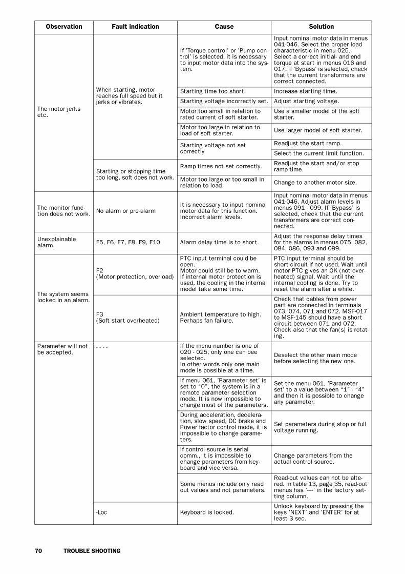
70 TROUBLE SHOOTING
The motor jerks etc.
When starting, motor reaches full speed but it jerks or vibrates.
If ’Torque control’ or ’Pump con-trol’ is selected, it is necessary to input motor data into the sys-tem.
Input nominal motor data in menus 041-046. Select the proper load characteristic in menu 025.Select a correct initial- and end torque at start in menus 016 and 017. If ’Bypass’ is selected, check that the current transformers are correct connected.
Starting time too short. Increase starting time.
Starting voltage incorrectly set. Adjust starting voltage.
Motor too small in relation to rated current of soft starter.
Use a smaller model of the soft starter.
Motor too large in relation to load of soft starter. Use larger model of soft starter.
Starting voltage not set correctly
Readjust the start ramp.
Select the current limit function.
Starting or stopping time too long, soft does not work.
Ramp times not set correctly. Readjust the start and/or stop ramp time.
Motor too large or too small in relation to load. Change to another motor size.
The monitor func-tion does not work. No alarm or pre-alarm
It is necessary to input nominal motor data for this function.Incorrect alarm levels.
Input nominal motor data in menus 041-046. Adjust alarm levels in menus 091 - 099. If ’Bypass’ is selected, check that the current transformers are correct con-nected.
Unexplainable alarm. F5, F6, F7, F8, F9, F10 Alarm delay time is to short.
Adjust the response delay times for the alarms in menus 075, 082, 084, 086, 093 and 099.
The system seems locked in an alarm.
F2(Motor protection, overload)
PTC input terminal could be open. Motor could still be to warm.If internal motor protection is used, the cooling in the internal model take some time.
PTC input terminal should be short circuit if not used. Wait until motor PTC gives an OK (not over-heated) signal. Wait until the internal cooling is done. Try to reset the alarm after a while.
F3(Soft start overheated)
Ambient temperature to high.Perhaps fan failure.
Check that cables from power part are connected in terminals 073, 074, 071 and 072. MSF-017 to MSF-145 should have a short circuit between 071 and 072. Check also that the fan(s) is rotat-ing.
Parameter will not be accepted.
- - - - If the menu number is one of 020 - 025, only one can bee selected.In other words only one main mode is possible at a time.
Deselect the other main mode before selecting the new one.
If menu 061, ’Parameter set’ is set to “0”, the system is in a remote parameter selection mode. It is now impossible to change most of the parameters.
Set the menu 061, ’Parameter set’ to a value between “1” - “4” and then it is possible to change any parameter.
During acceleration, decelera-tion, slow speed, DC brake and Power factor control mode, it is impossible to change parame-ters.
Set parameters during stop or full voltage running.
If control source is serial comm., it is impossible to change parameters from key-board and vice versa.
Change parameters from the actual control source.
Some menus include only read out values and not parameters.
Read-out values can not be alte-red. In table 13, page 35, read-out menus has ’----’ in the factory set-ting column.
-Loc Keyboard is locked.Unlock keyboard by pressing the keys ’NEXT’ and ’ENTER’ for at least 3 sec.
Observation Fault indication Cause Solution

MAINTENANCE 71
1 0 . M A I N T E N A N C E
In general the soft starter is maintenance free. There arehowever some things which should be checked regu-larly. Especially if the surroundings are dusty the unitshould be cleaned regularly.
WARNING! Do not touch parts inside the enclosure of the unit when the control and motor voltage is switched on.
Regular maintenance• Check that nothing in the soft starter has been dam-
aged by vibration (loose screws or connections).• Check external wiring, connections and control
signals. Tighten terminal screws and busbar bolts ifnecessary.
• Check that PCB boards, thyristors and cooling finare free from dust. Clean with compressed air ifnecessary. Make sure the PCB boards and thyristorsare undamaged.
• Check for signs of overheating (changes in colouron PCB boards, oxidation of solder points etc.).Check that the temperature is within permissiblelimits.
• Check that the cooling fan/s permit free air flow.Clean any external air filters if necessary.
In the event of fault or if a fault cannot be cured byusing the fault-tracing table in chapter 9. page 68.
!

72 OPTIONS
1 1 . O P T I O N S
The following option are available. Please contact yoursupplier for more detailed information.
11.1 Serial communicationFor serial communication the MODBUS RTU(RS232/RS485) option card is available order number:01-1733-00.
Fig. 60 Option RS232/485
11.2 Field bus systemsVarious option cards are available for the following bussystems:• PROFIBUS DP order number: 01-1734-01• Device NET, order number: 01-1736-01• LONWORKS: 01-1737-01• FIP IO: 01-1738-01• INTERBUS-S: 01-1735-01
Each system has his own card. The option is deliveredwith an instruction manual containing the all details forthe set-up of the card and the protocol for program-ming.
Fig. 61 Option Profibus
11.3 External PPU.The external PPU option is used to move the PPU(keyboard) from the soft starter to the front of a paneldoor or control cabinet.
The maximum distance between the soft starter andthe external PPU is 3 m.The option can be factory mounted (01-2138-01) or itcan be built in later (01-2138-00). For both versionsinstruction /data sheet are available.
Fig. 62 Shows an example of the External PPU after it has been built in.
11.3.1 Cable kit for external current transformers
This kit is used for the bypass function, to connect theexternal current transformers more easy. order number:01-2020-00.
Fig. 63 Cable kit
(03-F62)
Red
Brown
Bro
wn
Blue
Blue
Blu
e
Brown
Bro
wn
03-F120

OPTIONS 73
11.4 Terminal clampData: Single cables, Cu or AlCables 95-300 mm2
MSF type Cu Cable 310Bolt for connection to busbar M10Dimensions in mm 33x84x47 mmOrder No. single 9350Data: Parallel cables, Cu or AlCables 2x95-300 mm2
MSF type and Cu Cable 310 to -835Bolt for connection to busbar M10Dimensions in mm 35x87x65Order No. parallel 9351
Fig. 64 The terminal clamp.
41±0,547
33±0,5
30±0,5
60 8
3,5
70-300 mm
30±0,5
86
,5
2x95-300 mm
41±0,265
58
35±0,5
2x95-300 mm
70-300 mm
33±0.5
30±0.541±0.541±0.5
47
60
83
.5
35±0.5
41±0.230±0.5
86.5
58
65
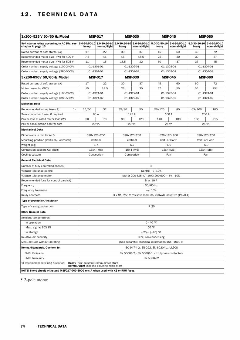
74 TECHNICAL DATA
1 2 . T E C H N I C A L D A T A
* 2-pole motor
3x200—525 V 50/60 Hz Model MSF-017 MSF-030 MSF-045 MSF-060
Soft starter rating according to AC35a, see chapter 4. page 13
5.0-30:50-10 heavy
3.0-30:50-10 normal/light
5.0-30:50-10 heavy
3.0-30:50-10 normal/light
5.0-30:50-10 heavy
3.0-30:50-10 normal/light
5.0-30:50-10 heavy
3.0-30:50-10 normal/light
Rated current of soft starter (A) 17 22 30 37 45 60 60 72
Recommended motor size (kW) for 400 V 7.5 11 15 18.5 22 30 30 37
Recommended motor size (kW) for 525 V 11 15 18.5 22 30 37 37 45
Order number: supply voltage (100-240V) 01-1301-01 01-1302-01 01-1303-01 01-1304-01
Order number: supply voltage (380-500V) 01-1301-02 01-1302-02 01-1303-02 01-1304-02
3x200-690V 50/60Hz Model MSF-017 MSF-030 MSF-045 MSF-060
Rated current of soft starter (A) 17 22 30 37 45 60 60 72
Motor power for 690V 15 18.5 22 30 37 55 55 75*
Order number: supply voltage (100-240V) 01-1321-01 01-1322-01 01-1323-01 01-1324-01
Order number: supply voltage (380-500V) 01-1321-02 01-1322-02 01-1323-02 01-1324-02
Electrical Data
Recommended wiring fuse (A) 1) 25/50 32 35/80 50 50/125 80 63/160 100
Semi-conductor fuses, if required 80 A 125 A 160 A 200 A
Power loss at rated motor load (W) 50 70 90 120 140 180 180 215
Power consumption control card 20 VA 20 VA 25 VA 25 VA
Mechanical Data
Dimensions in mm HxWxD 320x126x260 320x126x260 320x126x260 320x126x260
Mounting position (Vertical/Horizontal) Vertical Vertical Vert. or Horiz. Vert. or Horiz.
Weight (kg) 6.7 6.7 6.9 6.9
Connection busbars Cu, (bolt) 15x4 (M6) 15x4 (M6) 15x4 (M6) 15x4 (M8)
Cooling system Convection Convection Fan Fan
General Electrical Data
Number of fully controlled phases 3
Voltage tolerance control Control +/- 10%
Voltage tolerance motor Motor 200-525 +/- 10%/200-690 + 5%, -10%
Recommended fuse for control card (A) Max 10 A
Frequency 50/60 Hz
Frequency tolerance +/- 10%
Relay contacts 3 x 8A, 250 V resistive load, 3A 250VAC inductive (PF=0.4)
Type of protection/insulation
Type of casing protection IP 20
Other General Data
Ambient temperatures
In operation 0 - 40 °C
Max. e.g. at 80% IN 50 °C
In storage (-25) - (+70) °C
Relative air humidity 95%, non-condensing
Max. altitude without derating (See separate: Technical information 151) 1000 m
Norms/Standards, Conform to: IEC 947-4-2, EN 292, EN 60204-1, UL508
EMC, Emission EN 50081-2, (EN 50081-1 with bypass contactor)
EMC, Immunity EN 50082-2
1) Recommended wiring fuses for: Heavy (first column): ramp/direct startNormal/Light (second column): ramp start
NOTE! Short circuit withstand MSF017-060 5000 rms A when used with K5 or RK5 fuses.
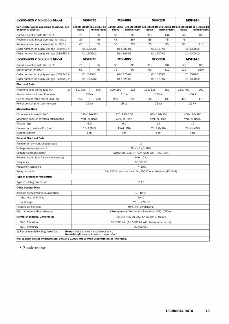
TECHNICAL DATA 75
* 2-pole motor
3x200—525 V 50/60 Hz Model MSF-075 MSF-085 MSF-110 MSF-145
Soft starter rating according to AC35a, see chapter 4. page 13
5.0-30:50-10 heavy
3.0-30:50-10 normal/light
5.0-30:50-10 heavy
3.0-30:50-10 normal/light
5.0-30:50-10 heavy
3.0-30:50-10 normal/light
5.0-30:50-10 heavy
3.0-30:50-10 normal/light
Rated current of soft starter (A) 75 85 85 96 110 134 145 156
Recommended motor size (kW) for 400 V 37 45 45 55* 55 75 75
Recommended motor size (kW) for 525 V 45 55 55 75* 75 90 90 110
Order number for supply voltage (100-240 V) 01-1305-01 01-1306-01 01-1307-01 01-1308-01
Order number for supply voltage (380-550 V) 01-1305-02 01-1306-02 01-1307-02 01-1308-02
3x200—690 V 50/60 Hz Model MSF-075 MSF-085 MSF-110 MSF-145
Rated current of soft starter (A) 75 85 85 90 110 134 145 156
Motor power for 690V 55 75 75 90 90 110 132 160*
Order number for supply voltage (100-240 V) 01-1325-01 01-1326-01 01-1327-01 01-1328-01
Order number for supply voltage (380-550 V) 01-1325-02 01-1326-02 01-1327-02 01-1328-02
Electrical Data
Recommended wiring fuse (A) 1) 80/200 100 100/250 125 125/315 180 160/400 200
Semi-conductor fuses, if required 250 A 315 A 350 A 450 A
Power loss at rated motor load (W) 230 260 260 290 330 400 440 470
Power consumption control card 25 VA 25 VA 25 VA 25 VA
Mechanical Data
Dimensions in mm HxWxD 320x126x260 320x126x260 400x176x260 400x176x260
Mounting position (Vertical/Horizontal) Vert. or Horiz. Vert. or Horiz. Vert. or Horiz. Vert. or Horiz.
Weight (kg) 6.9 6.9 12 12
Connection, busbars Cu, (bolt) 15x4 (M8) 15x4 (M8) 20x4 (M10) 20x4 (M10)
Cooling system Fan Fan Fan Fan
General Electrical Data
Number of fully controlled phases 3
Voltage tolerance control Control +/- 10%
Voltage tolerance motor Motor 200-525 +/- 10%/200-690 + 5%, -10%
Recommended fuse for control card (A) Max 10 A
Frequency 50/60 Hz
Frequency tolerance +/- 10%
Relay contacts 8A, 250 V resistive load, 3A, 250 V inductive load (PF=0.4)
Type of protection/insulation
Type of casing protection IP 20
Other General Data
Ambient temperatures In operation 0 - 40 °C
Max. e.g. at 80% IN 50 °C
In storage (-25) - (+70) °C
Relative air humidity 95%, non-condensing
Max. altitude without derating (See separate: Technical information 151) 1000 m
Norms/Standards, Conform to: IEC 947-4-2, EN 292, EN 60204-1, UL508
EMC, Emission EN 50081-2, (EN 50081-1 with bypass contactor)
EMC, Immunity EN 50082-2
1) Recommended wiring fuses for: Heavy (first column): ramp/direct startNormal/Light (second column): ramp start
NOTE! Short circuit withstand MSF075-145 10000 rms A when used with K5 or RK5 fuses.

76 TECHNICAL DATA
* 2-pole motor
3x200—525 V 50/60 Hz Model MSF-170 MSF-210 MSF-250 MSF-310 MSF-370
Soft starter rating according to AC35a, see chapter 4. page 13
5.0-30:50-10heavy
3.0-30:50-10
normal/light
5.0-30:50-10 heavy
3.0-30:50-10
normal/light
5.0-30:50-10 heavy
3.0-30:50-10
normal/light
5.0-30:50-10 heavy
3.0-30:50-10
normal/light
5.0-30:50-10 heavy
3.0-30:50-10
normal/light
Rated current of soft starter (A) 170 210 210 250 250 262 310 370 370 450
Recommended motor size (kW) for 400 V 90 110 110 132 132 160* 160 200 200 250
Recommended motor size (kW) for 525 V 110 132 132 160 160 200* 200 250 250 315
Order no. for supply voltage (100-240V) 01-1309-11 01-1310-11 01-1311-11 01-1312-01 01-1313-01
Order no. for supply voltage (380-550V) 01-1309-12 01-1310-12 01-1311-12 01-1312-02 01-1313-02
3x200—690 V 50/60 Hz Model MSF-170 MSF-210 MSF-250 MSF-310 MSF-370
Rated current of soft starter (A) 170 210 210 250 250 262 310 370 370 450
Motor power for 690 V 160 200 200 250 250 250 315 355 355 400
Order no. for supply voltage (100-240V) 01-1329-01 01-1330-01 01-1331-01 01-1332-01 01-1333-01
Order no. for supply voltage (380-550V) 01-1329-02 01-1330-02 01-1331-02 01-1332-02 01-1333-02
Electrical Data
Recommended wiring fuse (A) 1) 200/400 200 250/400 315 250/500 315 315/630 400 400/800 500
Semi-conductor fuses, if required 700 A 700 A 700 A 800 A 1000 A
Power loss at rated motor load (W) 510 630 630 750 750 W 930 1100 1100 1535
Power consumption control card 35 VA 35 VA 35 VA 35 VA 35 VA
Mechanical Data
Dimensions mm HxWxD incl. brackets 500x260x260 500x260x260 500x260x260 532x547x278 532x547x278
Mounting position (Vertical/Horizontal) Vert. or Horiz. Vert. or Horiz. Vert. or Horiz. Vert. or Horiz. Vert. or Horiz.
Weight (kg) 20 20 20 42 46
Connection, Busbars Al/Cu (bolt) 30x4 (M10) 30x4 (M10) 30x4 (M10) 40x8 (M12) 40x8 (M12)
Cooling system Fan Fan Fan Fan Fan
General Electrical Data
Number of fully controlled phases 3
Voltage tolerance control Control +/- 10%
Voltage tolerance motor Motor 200-525 +/- 10%/200-690 + 5%, -10%
Recommended fuse for control card (A) Max 10 A
Frequency 50/60 Hz
Frequency tolerance +/- 10%
Relay contacts 8A, 250 V resistive load, 3A, 250 V inductive load (PF=0.4)
Type of protection/insulation
Type of casing protection IP 20
Other General Data
Ambient temperatures In operation 0 - 40 °C
Max. e.g. at 80% IN 50 °C
In storage (-25) - (+70) °C
Relative air humidity 95%, non-condensing
Max. altitude without derating (See separate: Technical information 151) 1000 m
Norms/Standards, Conform to: IEC 947-4-2, EN 292, EN 60204-1, (UL508, only MSF-170 to MSF-250)
EMC, Emission EN 50081-2, (EN 50081-1 with bypass contactor)
EMC, Immunity EN 50082-2
1) Recommended wiring fuses for: Heavy (first column): ramp/direct startNormal/Light (second column): ramp start
NOTE! Short circuit withstand MSF170-250 18000 rms A when used with K5 or RK5 fuses.

TECHNICAL DATA 77
3x200—525V 50/60Hz Model MSF-450 MSF-570 MSF-710 MSF-835 MSF-1000 MSF-1400
Soft starter rating according to AC35a, see chapter 4. page 13
5.0-30:50-10heavy
3.0-30:50-10
normal/light
5.0-30:50-10 heavy
3.0-30:50-10
normal/light
5.0-30:50-10 heavy
3.0-30:50-10
normal/light
5.0-30:50-10 heavy
3.0-30:50-10
normal/light
5.0-30:50-10 heavy
3.0-30:50-10
normal/light
5.0-30:50-10 heavy
3.0-30:50-10
normal/light
Rated current of soft starter (A) 450 549 570 710 710 835 835 960 1000 1125 1400 1650
Recommended motor size (kW) for 400 V 250 315 315 400 400 450 450 560 560 630 800 930
Recommended motor size (kW) for 525 V 315 400 400 500 500 560 600 630 660 710 1000 1250
Order no. for supply voltage (100-240V) 01-1341-01 01-1315-01 01-1316-01 01-1317-01 01-1318-01 01-1319-01
Order no. for supply voltage (380-550V) 01-1314-02 01-1315-02 01-1316-02 01-1317-02 01-1318-02 01-1319-02
3x200—690V 50/60Hz Model MSF-450 MSF-570 MSF-710 MSF-835 MSF-1000 MSF-1400
Rated current of soft starter (A) 450 549 570 640 710 835 835 880 1000 1125 1400 1524
Motor power for 690 V 400 560 560 630 710 800 800 1000 1120 1400 1600
Order no. for supply voltage (100-240V) 01-1334-01 01-1335-01 01-1336-01 01-1337-01 01-1338-01 01-1339-01
Order no. for supply voltage (380-550V) 01-1334-02 01-1335-02 01-1336-02 01-1337-02 01-1338-02 01-1339-02
Electrical Data
Recommended wiring fuse (A 1) 500/1 k 630 630/1 k 800 800/1 k 1 k 1 k/1.2 k 1 k 1k/1.4 k 1.2 k 1.4 k/1.8 k 1.8 k
Semi-conductor fuses, if required 1250 A 1250 A 1800 A 2500 A 3200 A 4000 A
Power loss at rated motor load (W) 1400 1730 1700 2100 2100 2500 2500 2875 3000 3375 4200 4950
Power consumption control card 35 VA 35 VA 35 VA 35 VA 35 VA 35 VA
Mechanical Data
Dimensions mm HxWxD incl. brackets 532x547x278 687x640x302 687x640x302 687x640x302 900x875x336 900x875x336
Mounting position (Vertical/Horizontal) Vert. or Horiz. Vert. or Horiz. Vert. or Horiz. Vert. or Horiz. Vert. or Horiz. Vert. or Horiz.
Weight (kg) 46 64 78 80 175 175
Connection, Busbars Al (bolt) 40x8 (M12) 40x10 (M12) 40x10 (M12) 40x10 (M12) 75x10 (M12) 75x10 (M12)
Cooling system Fan Fan Fan Fan Fan Fan
General Electrical Data
Number of fully controlled phases 3
Voltage tolerance control Control +/- 10%
Voltage tolerance motor Motor 200-525 +/- 10%/200-690 + 5%, -10%
Recommended fuse for control card (A) Max 10 A
Frequency 50/60 Hz
Frequency tolerance +/- 10%
Relay contacts 8A, 250 V resistive load, 3A, 250 V inductive load (PF=0.4)
Type of protection/insulation
Type of casing protection IP 20 IP00
Other General Data
Ambient temperatures In operation 0 - 40 °C
Max. e.g. at 80% IN 50 °C
In storage (-25) - (+70) °C
Relative air humidity 95%, non-condensing
Max. altitude without derating (See separate: Technical information 151) 1000 m
Norms/Standards, Conform to: IEC 947-4-2, EN 292, EN 60204-1
EMC, Emission EN 50081-2, (EN 50081-1 with bypass contactor)
EMC, Immunity EN 50082-2
1) Recommended wiring fuses for: Heavy (first column): ramp/direct startNormal/Light (second column): ramp start

78 TECHNICAL DATA
Semi-conductor fusesAlways use standard commercial fuses to protect thewiring and prevent short circuiting. To protect the thy-ristors against short-circuit currents, superfast semicon-ductor fuses can be used if preferred (e.g. Bussmanntype FWP or similar, see table below).
The normal guarantee is valid even if superfast semiconductor fuses are not used.
TypeFWP Bussmann fuse
A I2t (fuse) x 1000
MSF-017 80 2.4
MSF-030 125 7.3
MSF-045 150 11.7
MSF-060 200 22
MSF-075 250 42.5
MSF-085 300 71.2
MSF-110 350 95.6
MSF-145 450 137
MSF-170B 700 300
MSF-210B 700 300
MSF-250B 800 450
MSF-310 800 450
MSF-370 1000 600
MSF-450 1200 2100
MSF-570 1400 2700
MSF-710 1800 5300
MSF-835 2000
MSF-1000 2500
MSF-1400 3500
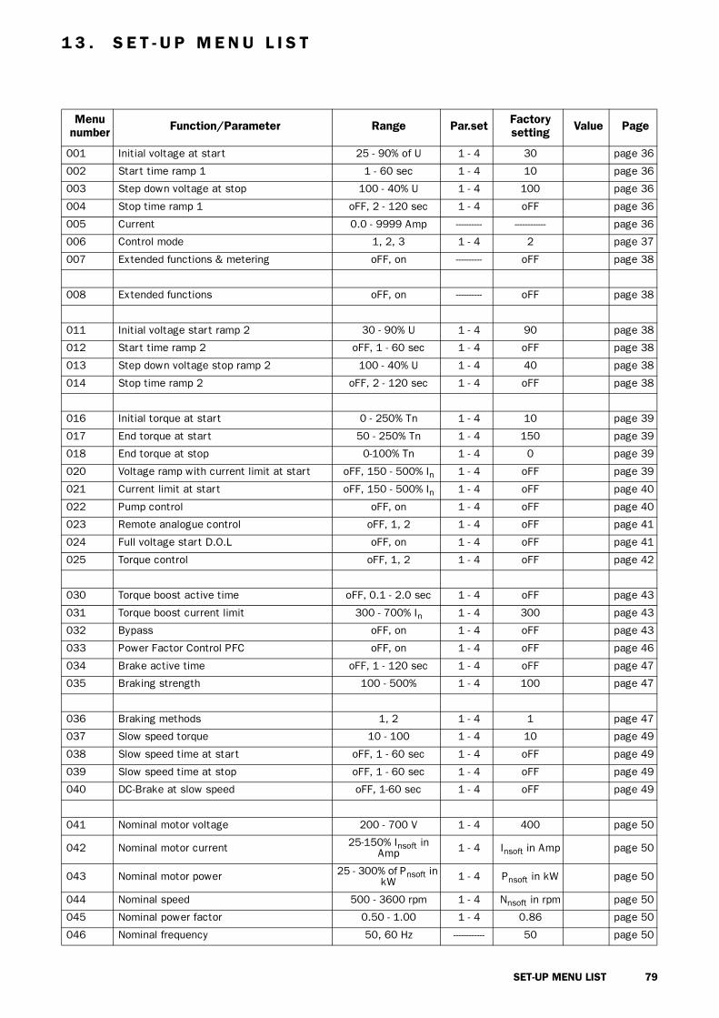
SET-UP MENU LIST 79
1 3 . S E T - U P M E N U L I S T
Menu number Function/Parameter Range Par.set Factory
setting Value Page
001 Initial voltage at start 25 - 90% of U 1 - 4 30 page 36
002 Start time ramp 1 1 - 60 sec 1 - 4 10 page 36
003 Step down voltage at stop 100 - 40% U 1 - 4 100 page 36
004 Stop time ramp 1 oFF, 2 - 120 sec 1 - 4 oFF page 36
005 Current 0.0 - 9999 Amp ---------- ------------ page 36
006 Control mode 1, 2, 3 1 - 4 2 page 37
007 Extended functions & metering oFF, on ---------- oFF page 38
008 Extended functions oFF, on ---------- oFF page 38
011 Initial voltage start ramp 2 30 - 90% U 1 - 4 90 page 38
012 Start time ramp 2 oFF, 1 - 60 sec 1 - 4 oFF page 38
013 Step down voltage stop ramp 2 100 - 40% U 1 - 4 40 page 38
014 Stop time ramp 2 oFF, 2 - 120 sec 1 - 4 oFF page 38
016 Initial torque at start 0 - 250% Tn 1 - 4 10 page 39
017 End torque at start 50 - 250% Tn 1 - 4 150 page 39
018 End torque at stop 0-100% Tn 1 - 4 0 page 39
020 Voltage ramp with current limit at start oFF, 150 - 500% In 1 - 4 oFF page 39
021 Current limit at start oFF, 150 - 500% In 1 - 4 oFF page 40
022 Pump control oFF, on 1 - 4 oFF page 40
023 Remote analogue control oFF, 1, 2 1 - 4 oFF page 41
024 Full voltage start D.O.L oFF, on 1 - 4 oFF page 41
025 Torque control oFF, 1, 2 1 - 4 oFF page 42
030 Torque boost active time oFF, 0.1 - 2.0 sec 1 - 4 oFF page 43
031 Torque boost current limit 300 - 700% In 1 - 4 300 page 43
032 Bypass oFF, on 1 - 4 oFF page 43
033 Power Factor Control PFC oFF, on 1 - 4 oFF page 46
034 Brake active time oFF, 1 - 120 sec 1 - 4 oFF page 47
035 Braking strength 100 - 500% 1 - 4 100 page 47
036 Braking methods 1, 2 1 - 4 1 page 47
037 Slow speed torque 10 - 100 1 - 4 10 page 49
038 Slow speed time at start oFF, 1 - 60 sec 1 - 4 oFF page 49
039 Slow speed time at stop oFF, 1 - 60 sec 1 - 4 oFF page 49
040 DC-Brake at slow speed oFF, 1-60 sec 1 - 4 oFF page 49
041 Nominal motor voltage 200 - 700 V 1 - 4 400 page 50
042 Nominal motor current 25-150% Insoft in Amp 1 - 4 Insoft in Amp page 50
043 Nominal motor power 25 - 300% of Pnsoft in kW 1 - 4 Pnsoft in kW page 50
044 Nominal speed 500 - 3600 rpm 1 - 4 Nnsoft in rpm page 50
045 Nominal power factor 0.50 - 1.00 1 - 4 0.86 page 50
046 Nominal frequency 50, 60 Hz ------------ 50 page 50

80 SET-UP MENU LIST
051 Programmable relay K1 1, 2, 3, (4), 5 1 page 51
052 Programmable relay K2 1, 2, 3, 4, 5 ----------- 2 page 51
054 Analogue output oFF, 1, 2 1 - 4 oFF page 52
055 Analogue output value 1, 2, 3 1 - 4 1 page 52
056 Scaling analogue output 5 - 150% 1 - 4 100 page 52
057 Digital input selection oFF, 1, 2, 3, 4 1 - 4 oFF page 53
058 Digital input pulses 1-100 1 - 4 1 page 53
061 Parameter set 0, 1, 2, 3, 4 ------------- 1 page 54
071 Motor PTC input no, YES ------------- no page 55
072 Internal motor thermal protection class oFF, 2 - 40 sec ------------ 10 page 55
073 Used thermal capacity 0 - 150% ------------- ------------ page 55
074 Starts per hour limitation oFF, 1 - 99/hour 1 - 4 oFF page 55
075 Locked rotor alarm oFF, 1.0 - 10.0 sec 1 - 4 oFF page 55
081 Voltage unbalance alarm 2 - 25% Un 1 - 4 10 page 56
082 Response delay voltage unbalance alarm oFF, 1 - 60 sec 1 - 4 oFF page 56
083 Over voltage alarm 100 - 150% Un 1 - 4 115 page 56
084 Response delay over voltage alarm oFF, 1 - 60 sec 1 - 4 oFF page 56
085 Under voltage alarm 75 - 100% Un 1 - 4 85 page 57
086 Response delay under voltage alarm oFF, 1 - 60 sec 1 - 4 oFF page 57
087 Phase sequence L123, L321 ------------ ------------ page 57
088 Phase reversal alarm oFF, on ------------ oFF page 57
089 Auto set power limits no, YES ------------ no page 57
090 Output shaft power 0.0 - 200.0% Pn ------------ ------------- page 57
091 Start delay power limits 1 - 250 sec 1 - 4 10 page 58
092 Max power alarm limit 5 - 200% Pn 1 - 4 115 page 58
093 Max alarm response delay oFF, 0.1 - 25.0 sec 1 - 4 oFF page 58
094 Max power pre-alarm limit 5 - 200% Pn 1 - 4 110 page 58
095 Max pre-alarm response delay oFF, 0.1 - 25.0 sec 1 - 4 oFF page 58
096 Min pre-alarm power limit 5 - 200% Pn 1 - 4 90 page 58
097 Min pre-alarm response delay oFF, 0.1 - 25.0 sec 1 - 4 oFF page 59
098 Min power alarm limit 5 - 200%Pn 1 - 4 85 page 59
099 Min alarm response delay oFF, 0.1 - 25.0 sec 1 - 4 oFF page 59
101 Run at single phase input failure no, YES 1 - 4 no page 61
102 Run at current limit time-out no, YES 1 - 4 no page 61
103 Jog forward enable oFF, on 1 - 4 oFF page 61
104 Jog reverse enable oFF, on 1 - 4 oFF page 61
105 Automatic return menu oFF, 1-999 ------------ oFF page 62
111 Serial comm. unit address 1 - 247 ------------- 1 page 62
112 Serial comm. baudrate 2.4 - 38.4 kBaud ------------- 9.6 page 62
Menu number Function/Parameter Range Par.set Factory
setting Value Page

SET-UP MENU LIST 81
Explanation of units:U Input line voltageUn Nominal motor voltage. In Nominal motor current. Pn Nominal motor power. Nn Nominal motor speed. Tn Nominal shaft torque. Insoft Nominal current soft starter. Pnsoft Nominal power soft starter. Nnsoft Nominal speed soft starter.
Calculation shaft torque
NOTE! The six main functions for motor control, menus 020—025, can only be selected one at a time.
113 Serial comm. parity 0, 1 ------------- 0 page 62
114 Serial comm. contact broken oFF, 1, 2 ------------- 1 page 62
199 Reset to factory settings no, YES ------------- no page 63
201 Current 0.0 - 9999 Amp ------------- ----------- page 63
202 Line main voltage 0 - 720 V ------------- ----------- page 63
203 Output shaft power -9999 - 9999 kW ------------- ----------- page 63
204 Power factor 0.00 - 1.00 ------------- ----------- page 63
205 Power consumption 0.000 - 2000 MWh ------------- ----------- page 63
206 Reset power consumption no, YES ------------- no page 64
207 Shaft torque -9999 - 9999 Nm ------------- ------------ page 64
208 Operation time Hours ------------- ------------ page 64
211 Current phase L1 0.0 - 9999 Amp ------------- ------------ page 64
212 Current phase L2 0.0 - 9999 Amp ------------- ------------ page 64
213 Current phase L3 0.0 - 9999 Amp ------------- ------------ page 64
214 Line main voltage L1 - L2 0 - 720 V ------------- ------------ page 64
215 Line main voltage L1 - L3 0 - 720 V ------------- ------------ page 64
216 Line main voltage L2 - L3 0 - 720 V ------------- ------------ page 64
221 Locked keyboard info no, YES ------------- no page 65
901 Alarm list, Latest error F1 - F16 ------------- --------------- page 65
902 -915 Alarm list, Older error in chronological order F1 - F16 ------------- --------------- page 65
Menu number Function/Parameter Range Par.set Factory
setting Value Page
TnPn
Nn60-------x2π -----------------------=

82 INDEX
1 4 . I N D E X
Numerics2-wire start/stop ............................ 373-wire start/stop ............................ 37
AAbove max power limit ................. 67Alarm category .............................. 67Alarm list ....................................... 65Alarm reset .................................... 23Ambient temperatures . 10, 20, 74, 75, 77analogue control ............................ 32Analogue input ........................ 32, 41Analogue output ...................... 32, 52Analogue output gain ..................... 52Analogue output value ................... 52Auto set power limits ..................... 57automatic reset ............................... 37Automatic return menu ................. 62
BBasic parameter setting ................... 10Below min power limit .................. 67Brake method ................................ 47Braking Strenght ............................ 47Braking time .................................. 46Busbars .................................... 25, 26Bypass ............................................ 43Bypass contactor ............................ 44
CCabinet .......................................... 24Checklist ........................................ 10Clickson thermistor ........................ 32Combination matrix ...................... 19Complaint .......................................7Confirm setting .............................. 23Connections ............................ 28, 32Control mode .......................... 23, 37Control voltage .............................. 32control voltage ............................... 33Control voltage connection ..... 28, 31Cooling fins ................................... 24cos phi ........................................... 50Current .......................................... 63Current in phase L1 ....................... 64Current in phase L2 ....................... 64Current in phase L3 ....................... 64Current limit ................................. 39Current limit time-out ................... 61Current transformer ....................... 45
DD.O.L start .................................... 41DC-brake ...................................... 46DC-Brake at slow speed ................. 49Decrease value ............................... 23Decrease value of setting ................ 23
Device connections .................. 28, 31different operation situation ........... 22Digital inputs ................................. 32Dimension ............................... 25, 74DIN VDE 0100 ............................. 24Direct On Line start ....................... 41Dismantling ..................................... 2Display next window ..................... 23Display previous window ............... 23Dual voltage ramp .......................... 38
EElectrical characteristic ................... 32Electrical Data .............. 74, 75, 76, 77EMC ........................... 74, 75, 76, 77Emergency ......................................2End torque .................................... 39
FFactory settings .............................. 63Features ........................................... 9Forward/reverse ............................ 34Free circulation of air ..................... 24frequency ....................................... 50Frequency inverter ......................... 20Front cover .................................... 21Full speed not reached ................... 67Full voltage .................................... 51Full voltage start ............................. 41Function ........................................ 79
GGeneral Data .................................. 74General description ........................ 21
HHeat dissipation ............................. 20High ambient temperatures ............ 43
IIncrease value ................................ 23Increase value of setting ................. 23Initial torque .................................. 39Initial voltage at start ramp 1 .......... 36Initial voltage at start ramp 2 .......... 38INSPECTION AT DELIVERY ..... 7Installation ..................................... 24Insulation test ................................. 20
JJOG Forward ........................... 23, 61JOG fwd/rev ................................. 23JOG Reverse ........................... 23, 61Jumper J1 ...................................... 41Jumper J2 ...................................... 52
KKeyboard ....................................... 23
Keyboard lock ......................... 23, 65keys ............................................... 23
LLED display ................................... 22Live circuit components ................. 24Load monitor ................................. 57Locked rotor .................................. 67Low load ....................................... 20
MMain functions ............................... 81Mains contactor ............................. 10Mains supply ............................ 28, 31Mains voltage ................................ 10MAINTENANCE ........................ 71Matrix ........................................... 19Max power alarm limit .................. 58Max power pre-alarm limit ............ 58Max pre-alarm response delay ........ 58Mechanical Data ...........74, 75, 76, 77Menu
001 ......................................... 36002 ................................... 11, 36003 ......................................... 36004 ................................... 11, 36005 ................................... 12, 36006 ................................... 12, 37007 ......................................... 38008 ......................................... 38011 ......................................... 38012 ......................................... 38013 ......................................... 38014 ......................................... 38016 ......................................... 39017 ......................................... 39020 ......................................... 39021 ......................................... 40022 ......................................... 40023 ......................................... 41024 ......................................... 41025 ......................................... 42030 ......................................... 43031 ......................................... 43032 ......................................... 43033 ......................................... 46034 ......................................... 46035 ......................................... 47036 ......................................... 47037 ......................................... 48038 ......................................... 49039 ......................................... 49040 ......................................... 49041 ................................... 11, 50042 ......................................... 50043 ................................... 11, 50044 ................................... 11, 50045 ................................... 11, 50046 ................................... 11, 50

INDEX 83
051 ......................................... 51052 ......................................... 51054 ......................................... 52055 ......................................... 52056 ......................................... 52057 ......................................... 53058 ......................................... 53061 ......................................... 54071 ......................................... 55072 ......................................... 55073 ......................................... 56074 ......................................... 56075 ......................................... 56081 ......................................... 56082 ......................................... 56083 ......................................... 56084 ......................................... 56085 ......................................... 57086 ......................................... 57087 ......................................... 57088 ......................................... 57089 ......................................... 57090 ......................................... 57091 ......................................... 58092 ......................................... 58093 ......................................... 58094 ......................................... 58095 ......................................... 58096 ......................................... 59097 ......................................... 59098 ......................................... 59099 ......................................... 59101 ......................................... 61102 ......................................... 61103 ......................................... 61104 ......................................... 61105 ......................................... 62199 ......................................... 63201 ......................................... 63202 ......................................... 63203 ......................................... 63204 ......................................... 63205 ......................................... 63206 ......................................... 64207 ......................................... 64208 ......................................... 64211 ......................................... 64212 ......................................... 64213 ......................................... 64214 ......................................... 64215 ......................................... 64216 ......................................... 64221 ................................... 23, 65901 ......................................... 65RMS current read-out ............ 12
Menu expansion ............................ 38Menu Structure ............................. 22Min alarm response delay ............... 59Min power alarm limit ................... 59Min power pre-alarm limit ............. 59Min pre-alarm response delay ......... 59Minimum free space ................ 24, 25Motor ............................................ 31
Motor current ................................ 50Motor data ..................................... 50Motor power ................................. 50Motor power supply ................ 28, 31Motor protection, overload ...... 55, 67Motor shaft torque ......................... 64Motor speed .................................. 50Motor terminal open ..................... 67Motor voltage ................................ 50MOUNTING ............................... 24MOUNTING/WIRING .............. 24
NNext .............................................. 23Nominal frequency ........................ 11Nominal motor cos phi .................. 11Nominal motor current ................. 11Nominal motor power ................... 11Nominal motor speed .................... 11Norms/Standards ......... 74, 75, 76, 77NTC thermistor ............................ 32
OOpen thyristor ............................... 67Operation ...................................... 51Operation time ........................ 63, 64Operation/Set-up .......................... 23Operator panel ............................... 21Output motor shaftpower .............. 63Output shaftpower ................... 57, 63Over voltage ............................ 56, 67
PParallel ........................................... 20Parallel cables ................................. 73Parameter ...................................... 79Parameter Set ........................... 32, 54PFC ............................................... 46Phase compensation capacitor ........ 20Phase input failure .......................... 67Phase loss ....................................... 61Phase reversal alarm ....................... 67Phase sequence .............................. 57Pole-changing contactor ................ 20Potentiometer ................................ 32Power consumption ....................... 63Power factor .................................. 63Power Factor Control .................... 46Power loss ..................................... 10PPU unit ....................................... 21Pre-alarm ................................. 51, 58Prevent damage to the thyristors .... 24Previous ......................................... 23Programmable relay ....................... 51Programming and presentation unit(PPU) ............................................ 21protection/insulation ... 74, 75, 76, 77Protective earth ....................... 28, 31PTC .............................................. 55PTC Thermistor input ................... 32Pump control ................................. 40
QQuick Set-up ................................. 10
RRating plate ................................... 10Recyclable material .......................... 2Regular maintenance ..................... 71Relay K1 ................................. 32, 51Relay K2 ....................................... 32Relay K3 ....................................... 32Remote ......................................... 23Reset ............................................. 23reset ............................................... 66Response delay max alarm ............. 58RMS current ........................... 36, 63RMS main voltage ......................... 63Rotating loads ............................... 20Running motors ............................ 20Running-LED ............................... 22
SSafety ........................................... 2, 6Safety measures .............................. 10Scrapping ......................................... 2Selection of control mode .............. 12Semiconductor fuses ................ 33, 78Serial comm. .................................. 23Serial communication broken ........ 67Shaftpower .............................. 57, 63Shielded motor cable ..................... 20Shorted thyristor ............................ 67Simple soft start and soft stop ......... 10Slip ring motors ............................. 20Slow blow fuses ............................. 33Slow speed time at start .................. 49Slow speed time at stop .................. 49Slow speed torque ......................... 48Small motor ................................... 20Softbrake ....................................... 51Softstart overheated ........................ 67Spare parts ....................................... 2standard commercial fuses .............. 78Standard wiring ....................... 10, 33Standards ......................................... 6Start command .............................. 22Start delay power limits .................. 58Start ramp 1 ................................... 36Start ramp 2 ................................... 38Start the motor .............................. 12Start time ramp 1 ........................... 11Start/Stop ................................ 12, 23Start/stop combination .................. 19Start/stop/reset from keyboard ...... 12Start/stop-LED .............................. 22Starting .......................................... 12STARTING/OPERATING ......... 79Starts per hour ............................... 67Starts per hour limitation ............... 56Step down voltage in stop ramp 2 .. 38Step down voltage stop ramp 1 ...... 36Stop command .............................. 22Stop ramp 1 ................................... 36

84 INDEX
Stop ramp time 2 ........................... 38Stop time ramp 1 ........................... 11storage .............................................7Supply voltage ......................... 32, 74switch ..............................................2Switch the device off .......................2Switch-off procedures ......................2
TTECHNICAL DATA ................... 74Terminal ........................................ 32Terminal clamp .............................. 78Terminals ....................................... 32Thermal capacity ........................... 56Thermal protection ........................ 55Tightening torque .......................... 25Torque boost active time ............... 43Torque boost current limit ............. 43Torque booster .............................. 43Torque control .............................. 42Trained personnel ...................... 2, 10Transport .........................................7TROUBLESHOOTING .............. 68Two speed motor .......................... 20
UUnder voltage .......................... 57, 67Unpacking .......................................7
VVIEW OPERATION ................... 63Voltage .......................................... 63Voltage unbalance .................... 56, 67
WWeight .......................................... 74Wiring circuit ................................ 33Wiring example ............................. 34

INDEX 85
R E P R E S E N T A T I O N
ADL Co.P.O. Box 47 12 50 40 MOSCOWRussiaTel. 00007- 095268 7423Fax 00007- 095268 [email protected]
AUTOMATECH Sp.zo.oul. Ry´zowa 84PL-02482 OPACZ-KOLONIA PolandTel. 0048- 22-723 06 62Fax 0048- 22-723 06 [email protected]
Elimko8. Cadde 68. Sokak Nr. 1606510 Emek-ANKARATurkeyTel. 0090 - 312 212 64 50 Fax 0090 - 312 212 41 43
Elpro Drive , S. R. O.ul. Miru 3CZ 73961 TRINECTjeckien RepublicTel. 00420W 659434661Fax 00420W [email protected]
Emotron ABBox 222 25SE-250 24 HELSINGBORGSwedenTel. +46 42 169900Fax +46 42 [email protected]
Emotron Antriebssysteme GmbHGoethestrasse 638855 WERNIGERODEGermanyTel. 0049- 3943 92050Fax 0049- 3943 [email protected]
Emotron B.V.P.O. Box 1325531 NX BLADELHollandTel. 0031- 497 389222Fax 0031- 497 [email protected]
Emotron Drives (UK) LtdSpaces Business CentreRadway Green ParkAlsagerCheshireCW2 5PRGreat BritainTel. 0044- 1270 879440Fax 0044- 1270 [email protected]
Emotron El-Fi SAAribau 229ES-08021 BARCELONASpainTel. 0034- 93 209 14 99Fax 0034- 93 209 12 [email protected]
Emotron Inc3440 Granite CircleTOLEDO, OH 43617 USATel. 001- (419) 841-7774Fax 001- (419) [email protected]
Emsby27 Rodwell StreetQUE - 4108 ARCHERFIELD AustraliaTel. 0061- 7 3274 2566Fax 0061- 7 3274 [email protected]
Esquire Engineering sdn bhd13, Jln Jurutera U1/23, Seksyen U1Hicom-Glenmarie Industrial Park40000 Shah Alam SELANGORMalaysiaTel. 0060- 3 519 1958Fax 0060- 3 519 1960 [email protected]
HEDTEC OYP.O.B 110SF-00201 HELSINGFORSFinlandTel. 00358- 9 682881Fax 00358- 9 [email protected]
Ingeniör Ivar Pettersen ASPostboks 166N-3001 DRAMMENNorwayTel. 0047- 32 21 21 21Fax 0047- 32 21 21 [email protected]
K.K. El-Fi2-18-4 Hagoromocho1900021 TachakawaJ- TOKYOJapanTel. 0081- 42 528 8820Fax 0081- 42 528 [email protected]
MAS for Eng. & TradFrom Tahreer St12, a-Abee Ema´ma St.DOKKI GIZAEgyptTel. 0020- 2 3357947Fax 0020- 2 3357948
Mohamad Eid KariMarjeh -square, Euphorat st. DagestaniBld. 1st. Fl. POB 31203DAMASKUSSyriaTel. 00963- 11 222 3867Fax 00963- 11 224 5425
Pardis InternationalGolbarg W. KermanS. Rahmati E. No.202TEHERANIranTel. 0098- 21 7838571Fax 0098- 21 [email protected]
Saftronics (PTY) LTD27 Heronmere RoadP O Box 380452016 BOOYSENSSouth AfricaTel. 0027- 11 434 1345Fax 0027- 11 434 [email protected]
TENSON Engineering LtdRoom 908, Nan Fung Commercial Center19 LAM LOK StKOWLOON BAYHong KongTel. +852 2758 0878Fax +852 2759 [email protected]
WELLFORD CHILE S.A.ENCALA 103645Madrid No 1602 - SantiagoSANTIAGOChileTel. 0056- 2 556 26 55Fax 0056- 2 556 35 [email protected]
Voltampere s.a.2nd klm Lagada-RedinaGR-57200 THESSALONIKIGreeceTel. 0030- 394 26188Fax 0030- 394 [email protected]
www.emotron.com

M A X I M I Z I N G U P T I M E
Art
icle
num
ber
01-1
363-
01 r
.2