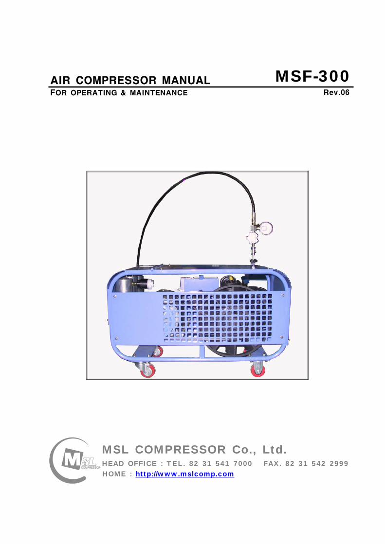
msf-300_air compressor
DESCRIPTION
INSTRUCTION MANUALTRANSCRIPT
MSL COMPRESSOR Co LtdHEAD OFFICE TEL 82 31 541 7000 FAX 82 31 542 2999HOME httpwwwmslcompcom
AIR COMPRESSOR MANUALFOR OPERATING amp MAINTENANCE
MSF-300Rev06
WARNINGWARNING
Safety Precautions
Please refer to the Safety Precautions and use accordingly The precautions specifically
mentioned in this reading material are of great importance concerning safety so please
follow as noted The dangers of misuse are divided into three categories
DANGER984023 Ignoring this notice may result in death andor fatal injury and can face
extreme danger
WARNING984023 Ignoring this notice may result in death andor fatal injury
CAUTION984023 Ignoring this notice may result in injury and damage to property
1 Product Guarantee and Service
Our company guarantees the performance of all products for one calendar year
from the date of purchase Our guarantee pertains to the full understanding of the
instructions transport and installation of the product We offer full service to
support the quality of the product as noted in the instructional manual Parts for
repair andor replacement covered by the guarantee period is exclusively supplied
by msl compressor The consumer will be responsible for all shipping
costs involved with parts for repair andor replacement
Any inquiries concerning repair and replacement can be directed to
msl compressor operations department
MSL COMPRESSOR Service Center (Operations Department) 82 31 541 7000
Thank you for purchasing this product
For maximum performance and safety please read and refer to the following
instructions
Please keep this reading material accessible to the operator in charge of the
equipment
2 Safety Precautions
984023 CAUTION
Use only tanks that have been inspected and never pass the pressure limit asnoted on the tank
Do not use contaminated gases Do not use in an area with heavy dustWhen not in use keep in an open areaFilter should be replaced regularly as noted in the instruction manual(Important Refer to filter replacement instructions prior to replacement)
Do not inject oil or fuels during useTo prevent overheating cool equipment 30 minutes after starting useUser should master instructions and safety precautions in this manual prior tousing the equipmentInstallation area needs to be free of chemicals and debrisInstallation surface needs to be free of erosionInstall in an area with open air flow and minimal exposure to weather conditions
3 WARNING
984023 WARNING
Owner of the equipment should always emphasize precaution to the operatorAccidents should be avoided through careful observation of abnormalities suchas irregular noise from the equipment
Equipment parts should not be altered or relocated in any formFailure to use recommended parts may result in accidentsDo not remove or alter safety stickers or safety valvesAlways examine equipment for missing and irregular partsNotify us in the event of any discovery of defects after posting a sign alertingthe equipment out of order
Machinery should always be operated in right lighting Lighting too bright or toodark may lead to accidents in operating the equipment
Always check the status of oil and need for changing of oilAlways check the power supply current for the equipment
4 DANGER
984023 DANGER
Do not touch the equipment during operationDo not use flammable cleaners during maintenanceDo not climb the equipmentOperators should always weara safety suit gloves headwear and other itemsfor safety Jewelry should not be worn during operation
Equipment should be installed on a level and flat surface
5 SAFETY EQUIPMENT AND INDICATORS
SAFETY EQUIPMENT
Safety Valve Pressure Switch
Electrical Overload Meter Pressure Gauge
Safety Fully Net
Automatic water drain
No INDICATOR
1 Overheat
2 Electrical Shock
3 Warning
4 Ear Protection Required
5 Clear hands from V-belt
6 Refer to manual oil needed
7 Operation temperature limit
8 Drain
9 Horizontal Placed
SAFETY INDICATORS
6 OTHER DANGERS
Possible oilgas mixture release in the event of an oil leak Possible electrical shock from water and humidity Possible accidents from operating the equipment not in accordance to the
instructions
Possible high decibel noise Possible fire hazards in haphazard handling of fuels Possible drive belt friction Possible erosion near the cooling fan Possible injury from a missing valve in the course of compression
MSL COMPRESSOR AIR COMPRESSOR MANUAL
1
TABLE OF CONTENTS
page no
1 Safety principles 2
2 The regulation of safety prior to operation 2
3 Technical Data 4
4 Applied model 5
5 Installation 6
6 Operation 6
7 Maintenance 9
8 Troubleshooting 15
9 Preventive Maintenance 16
APPENDIX (PART LIST)
- PART LIST
- AIR FLOW DIAGRAM
- ELECTRIC DIAGRAM
MSL COMPRESSOR AIR COMPRESSOR MANUAL
2
1 Safety Principles
1-1 General
The user must observe safety principles to prevent accident during operation The user must pay attention to preventive maintenance table to prevent accident
1-2 Safety Principles
This machine is designed and constructed for only breathing air compressor so userhave not to use for other purposes
Only skilled-person can access to the machine during operation Machine operation can be stopped by pressing switch stop in danger situationsThe main power supply must always disconnected after operation
The power transmission belt guards should not be opened except checkingmain power supply
2 The regulation of safety prior to operation
2-1 The breathing air compressor generated so much heat that the user have to
avoid a direct ray of light
2-2 To prevent machine damage by particles and dusts you must avoid unclean area
2-3 Can be supplied enough power after confirming voltage and electric current
2-4 Use standard lubrication oil recommended by manufacturer and changes oil
periodically
2-5 Pay attention not to flow in water to the air intake port
2-6 Periodically the user drain condensation water not to impede air flow
2-7 Do not adjust pressure regulator without manufacturers agreement
2-8 Use air filter recommended by manufacturer
2-9 Use air filter recommended by manufacturer
MSL COMPRESSOR AIR COMPRESSOR MANUAL
3
Manufacturer
Company MSL COMPRESSOR Co Ltd
Address 553 Seolun-dong Pocheon-si Kyonggi-do
487-030 KOREA
TEL 82 31 541 7000 FAX 82 31 542 2999
Preparation before use
Be desirable to use the quantity of BOTTLE recommended from manufacturer
Observe the operating and relaxing time of the machine
Do the test working more five minutes in winter or after keeping it for a long time
In case of abnormal operating directly call the manufacturer
Safety Device
Pressure switch Set the pressure and Can stop the compressor in the
automatically setted pressure when the air is filled up
Overload Relay Inform the user of overload situation
Safety valve Inform the user of abnormal operating
Safety Guard Protect the machine from an obstacle
MSL COMPRESSOR AIR COMPRESSOR MANUAL
4
3 TECHNICAL DATA
MODEL NO MSF-300
DELIVERY ( min)ℓ 150
OPERATING PRESSURE ( ) 200
SAFETY VALVE SETTING PRESSURE ( ) 220
PRESSURE SWITCH SETTING PRESSURE ( ) 200
SIZE (mm) L890 x W490 x H460
WEIGHT ( ) 965
COMPRESSOR SPECIFICATION
NUMBER OF STAGES 3
NUMBER OF CYLINDERS 3
CYLINDER BORE 1 STAGE (mm) 65
CYLINDER BORE 2 STAGE (mm) 24
CYLINDER BORE 3 STAGE (mm) 13
PISTON STROKE 26
SPEED (rpm) 1750
INTERMEDIATE PRESSURE 1 STAGE ( ) 7
INTERMEDIATE PRESSURE 2 STAGE ( ) 40
COMPRESSOR BLOCK OIL CAPACITY ( )ℓ 08
AMBIENT TEMPERATURE ( ) 5 sim 45
PERMISSIBLE INCLINATION OF COMPRESSOR ( ) 5
BELT SIZE (inch) A-47
PULLEY SIZE (inch) 7
MOTOR SPECIFICATION
POWER (HP(kW)) 3(255)
SPEED (rpm) 3480
PULLEY SIZE (inch) 35
Free air delivered at bottle filling 0 to 300 plusmn5
MSL COMPRESSOR AIR COMPRESSOR MANUAL
5
4 Applied MODEL
1 SUCTION FILTER
2 CONTROL BOX
3 START SW
4 PRESSURE SW
5 OIL DRAIN
6 WHEEL
7 OIL GAUGE
8 ONOFF SW
9 AIR CLEANING FILTER
10 MOTOR
MSL COMPRESSOR AIR COMPRESSOR MANUAL
6
5 Installation
5-1 Installation area
be well-ventilated
keep out of the sun snow and rain
The place having a little effect on the weather
The flat ground
5-2 Requirements for Environmental condition
No erosion
No the inflammables
No explosive gas
Clean area
No an interference around the COMPRESSOR
5-3 Install Base
Be far at least 500mm from a wall for the COOLING amp MAINTENANCE of COMPRESSOR
Install the SUCTION FILTER in the outside
Install the engine ventilation opening and suction filter to be the maximum distance
6 Operating
6-1 The user position of the COMPRESSOR
Be located near the STOP SWITCH of COMPRESSOR
6-2 The check condition of a trial run
Check the electric current complied with the electrical specifications of motor
Check the hindrance around rotating area
Check the oil capacity
Check the filter location if it is keep out of the sun snow and rain or not
Check the tightness of bolt and the leakage of air
Check the tension of BELT
Be well acquainted with preventive maintenance check list
MSL COMPRESSOR AIR COMPRESSOR MANUAL
7
6-3 Operating Procedure
Connect plug to receptacle or connect power conductor to load side of power
disconnecting device of power supply and turn the power disconnecting device
witch ON
Connect power conductor L1 L2 and L3 to the terminal of NFBS line side and
check whether compressor turns in accordance with an arrow direction or not If its
not interchanges conduct L2 and L3 and try again(check the phase sequence)
Electric power is supplied with on of NFB(None Fused Breaker)
(If a compressor power is over 5HP then red light turns on)
Combine by turning the connector of inlet hose
FOR 150200Kg METHOD FOR 300Kg
CONNECT
DISCHARGE
VALVE AND AIR
TANK
OPEN THE
DISCHARGE VALVE
(CCW)
LOCK THE
VENTING
VALVE (CW)
CAUTION
DO NOT FASTEN
TIGHTLY
MSL COMPRESSOR AIR COMPRESSOR MANUAL
8
Turn on the DISCHARGE VALVE of compressed air
Turn off the VENTING VALVE by turning to CW direction
(Be careful of the damage of packing and air leakage)
If you select the pressure level according to users equipment and illuminated
push button switch automatically turns on at the selected level
If the illuminated push button is pressed at properly selected level then the
compressor can start
If air tank is filled up by selected pressure level the motor will be turn off
and condensing water will be drained automatically(Option)
Turn off the pressure selector switch
Turn off(close) the air tank DISCHARGE VALVE
Drain the residual compressed air by turning VENTING VALVE
(Caution Prior to disconnecting of compressed air supply connector(valve)
residual compressed air in the supplying line must be vented out)
To disconnect compressed air supply connector from air tank
Turn the compressed air supply connecting valve to CCW direction
When fill-up operation is completed turn the main power supply tooff position
and drain the condensing water by opening the hand-operated valve below filter
MSL COMPRESSOR AIR COMPRESSOR MANUAL
9
7 Maintenance
7-1 Check OIL
Check the Oil status before starting a
machine
pour the Oil when it is needed l after
checking oil status
OIL TYPE BREATHING AIR COMPRESSOR OIL
7-2 AIR SUCTION FILTER
Install the suction filter on the outside
Filter the dust of air
Use the ELEMENT after cleaning when it is
dirty
exchange ELEMENT when it is impossible to use
Using the soiled filter is not good for performance
power consumption and durability
7-3 DRAIN VALVE
Extract the water by opening the drain valve when job is finished
AUTO DRAIN VALVE is automatically opened when the COMPRESSOR is stoped
AUTO DRAIN VALVE isnt worked on condition of having a some trouble in the
SOLENOID VALVE
Be required spacial attention in winter
- Be careful of damaging the COMPRESSOR BODY and LINE by the frozen air line
- Use the hot stove to melt the frozen DRAIN VALVE
- Always operate the ELECTRIC HEATER(Option) in wintertime if there is needed
7-4 PRESSURE GAUGE
AIR PRESSURE GAUGE denotes the pressure of air serviced and OIL PRESSURE
GAUGE denotes that of LUBRICATION OIL
PRESSURE GAUGE is required of special attention for a shock not to smash
Immediately exchange on condition of being damaged
Exchange PRESSURE GAUGE to certified one
SUCTION FILTER
MSL COMPRESSOR AIR COMPRESSOR MANUAL
10
7-5 SAFETY VALVE
SAFETY VALVE protects the machine for the higher pressure than settled pressure
Must be careful of the safety valve
Must be careful of the enclosed SAFETY VALVE
Immediately exchange the damaged SAFETY VALVE
In case of changing for a safety valve you must contact with a manufacturer
Do not touch SAFETY VALVE without manufacturers authorization
Only skilled engineer can regulate safety valves setting pressure
(Caution Never exceed over 110 of rated pressure)
SAFETY VALVE TYPE-I
High pressure settingTurn the PRESSURE ADJUST SCREW to CW①after loosening the LOCK NUT②Turn the LOCK NUT to CWafter setting②the pressure watching the Pressure gauge
Low pressure setting
Turn the PRESSURE ADJUST SCREW toCCW①after loosening the LOCK NUT②Turn the LOCK NUT toCW after setting②the pressure watching the pressure gauge
SAFETY VALVE TYPE-Ⅱ
High pressure setting
Turn the PRESSURE ADJUST SCREW to① CWafter loosening the LOCK NUT②Turn the LOCK NUT toCW after adjusting②the pressure watching the pressure gauge
Low pressure settingTurn the PRESSURE ADJUST SCREW to CCW①after loosening the LOCK NUT②Turn the LOCK NUT toCW after adjusting②the pressure watching the pressure gauge
FIG5 TYPE-Ⅱ
FIG4 SAFETY VALVE
TYPE-I
MSL COMPRESSOR AIR COMPRESSOR MANUAL
11
7-6 Other safety Device
PRESSURE SWITCH
Can stop running of compressor in case of over pressured situation
CCW PRESSURE UP CW (CLOCKWISE)
CW PRESSURE DOWN CCW (COUNTER CLOCKWISE)
THERMAL RELAY
- In case of the motors being stopped by overload settle the problem and
press the reset bar then relay will run because relay is standardized by the reset
method of hand-operated
- Check the screw and Fasten it per 4 months
- Clean electromagnetic contact surface per 4 months to remove the reason of noise
- Adjust control circuits voltage to rated voltage of operating coil as exactly as
possible
7-7 MOTOR
Checking points
- Check if the motor shaft can smoothly rotate by the hand or not
- Check The Belt tension and specifications in case of exchanging it
- Check if the power supply(Voltage Frequency Phase)is conform to name plate
- Power connections are performed after verifying the conformity with that of
name plate
Check during Operation
- The operating current of continually used motor must be lower than marked
(name plate) current If the operating current is higher than marked current
check the motor
- In order to check the rotation direction and wiring operate motor under no
loading
- If the rotating direction is reversed interchange two lines among three lines
FIG6 PRESSURE SW
MSL COMPRESSOR AIR COMPRESSOR MANUAL
12
7-8 AIR CLEANING FILTER
Compressed air is purified by filter so you must change filter per every 50 hours
The filter is consist of three small size (1 2 3 step filtering) or big one size
(1 step filtering)
In case of the filter of small sizes change
A and B step filter with new one and
one step filter can be reused by cleaning
Change filter
- Turn the filter case to CCW with supplied
filter opener and resolve it
- Change new one after cleaning the inner space
- Carefully turn the filter case to CW not to
damage the o-ring
① ② ③ ④ ⑤
7-9 Checking items after operation
Must open the drain valve after compressing operation to drain compressed water
Compressor heated is needed for changing compressor oil
FIG7 AIR CLEANING
FILTER
MSL COMPRESSOR AIR COMPRESSOR MANUAL
13
7-10 Ambient conditions for preservation
Operate compressor at least 10 minutes per a week because Compressors not
running for a long time causes a failure of the machine
Keep the compressor being covered indoor where is dry and clean
Always clean the COMPRESSOR
Check the compressor periodically with maintenance table or decrease of life time
and bad performance will be caused
In case of keeping of COMPRESSOR in damp condition for a long time it needs
unloaded rotation to get compressor oil into the cylinder after removing of the filter
A compressor installed with UNLOAD EQUIPMENT needs oil lubrication after
removing of connection nipple
7-11 V-belt tension
Readjust new V-belt after the first 25 operating hours
The best tension for a belt drive is the lowest possible where the belt under
full load does not slip
A rough value for this is when the belt deflects 10 when pressed with thumb
pressure between the two pulleys
FIG8 BELT TENSION
10 mm
MSL COMPRESSOR AIR COMPRESSOR MANUAL
14
7-12 Torque sequence
Lighten valve head and cylinder boltsnuts equally in the sequence shown in
figuration
FIG9 TORQUE SEQUENCE
7-13 Tightening torque values
Unless otherwise specified in text the following torque values apply
All valve head screws require torque wrench tightening
The indicated torque values are valid for bolts in greased condition
Replace self-retaining nuts on reassembly
BOLT TYPE BOLT SIZE MAX TORQUE
HEXAGON BOLT M6 10 Nm
HEXAGON BOLT M8 25 Nm
HEXAGON BOLT M10 45 Nm
HEXAGON BOLT M12 75 Nm
HEXAGON BOLT M14 120 Nm
HEXAGON BOLT M16 200 Nm
7-14 CLEAN SEPARATOR
Remove and clean sintered filter element as follows or exchange it if completely
clogged
Remove piping connected to filter head Remove filter head along with sintered
filter element
Remove centre screw and separate sintered filter element baffle and vortex
plate from the filter head
To clean filter element use hot soapy water and blow dry with compressed air
MSL COMPRESSOR AIR COMPRESSOR MANUAL
15
8 Troubleshooting
Problem Reason Action
No rotation1Burn out of cylinderand piston
Service to manufacturer
COMPRESSOR overheat
1Failure of ventvalve2Obstructed suctionfilter
Change valve
Clean and change of filter
Fill up time is too long
1Failure of suction valve2Air line leakage3Failure of nipple4Obstructed suction filter5Failure of unload valve
Change valve Change the line with air leakage Check the nipple Clean and change of suction filter Applied lubrication oil after removement of unload nipple
Abnormal noise
1Worn down2Shortage of oil3Obstructed suction filter
Change parts Supply oil Check filter
No rotation of MOTOR
1A stoppage of electriccurrent2A break in a wire3Failure of motor starter4Bad contacting
Check the incoming wire connection Check wire disconnection Check the contact point Fasten the terminal screw Check switch
Overheated motor
1Overload2Fluctuation of Supplingvoltage and Frequency3Over voltage and voltagedips4Dad cooling
Check the rated current Check the voltage and frequency
Clean the cooling area
Reverse rotation ofmotor
1Main power supplyconnection error
Check the 3phase sequence
Can not startengine(In case of usingengine instead ofmotor)
1Discharged battery2Bad contact of electricequipment3Failure of start motor4Bad contact5Failure of generator
Fasten terminal screw fully Check switch function
Check power cable Change generator Refer to the engine manual
Electrical error
1Unexpected protectivefunction(Turn-off) of NFB
2Malfunctioning ofpressure switch
Check short-circuit Overload(Rating and setting of overcorrect protectivedevices)
Check power wire Check air line Check selected pressure Change PRESSURE SWITCH
Failure of autodrain valve
1Malfunctioning of solvalve
2Malfunctioning ofautomatic drain valve
Change SOLENOID VALVE Obstructed air line by ingress of solid bodies and liquids(Clean the line)
Check the line in the wintertime against rupture by freezing Check the wiring Ingress of solid bodies and liquids(Clean up everything) In the wintertime obstructed air line by freezing(Melt by Hot air gun)
Check air line
Failure of safetyvalve
1Ingress of external solidbodies and liquids
Clean up the ingress of solid bodies and liquids Change safety valve
AIR condensationtime is too long
1 Check the air line leakage(Verify the air line leakage under main power off afterrise up air line pressure at 150
2 Check the air leak about drain during operating conditionIf there air leakage detected change SOLENOID VALVE
3 Check the third and fourth step head and pipe NIPPLE
MSL COMPRESSOR AIR COMPRESSOR MANUAL
16
9 Preventive Maintenance
ACTIONPERIOD
TIMEHOUR DAY WEEK MONTH
QUAR-TER
HALF-YEAR YEAR
2YEAR
Clean and assembling condition
(each part of compressor)
Check CRANK CASE OIL
Check DRAIN VALVE
Check AIR leakage
Check PRESSURE GAUGE
Check PRESSURE Switch
Clean SUCTION FILTER
Check SAFETY VALVE
Check BELT tension
Change SUCTION FILTER
Check SUCTION amp DISCHARGE VALVE
CheckChange OIL FILTER ELEMENT
Change CRANK CASE OIL 50
Change DISCHARGE FILTER ELEMENT 50
Check SEPARATOR
Clean SEPARATOR
Check piston ring
MSL COMPRESSOR AIR COMPRESSOR MANUAL
P A R T L IS TMODEL MSF-300
MSL COMPRESSOR Co LtdHEAD OFFICE TEL 82 31 541 7000 FAX 82 31 542 2999HOME httpwwwmslcompcom
MSL COMPRESSOR AIR COMPRESSOR MANUAL
18
MSL COMPRESSOR AIR COMPRESSOR MANUAL
B HEAD ASSY
MSL COMPRESSOR AIR COMPRESSOR MANUAL
B HEAD ASSYKEY No PART No DESCRIPTION (Qty) NOTE
01 B-300-A-001 CRANK CASE
02 B-300-A-002 OIL GAUGE
03 B-300-F-001 SNAP RING
04 B-300-A-003 CRANK SHAFT
05 B-300-A-004 KEY
06 6306 BEARING
07 B-300-G-001 GASKET
08 B-300-A-005 BEARING COVER
09 B-300-A-006 OIL SEAL
10 6305ZZ BEARING
11 B-300-A-007 PULLEY
12 B-300-B-001 WASHER
13 B-300-B-002 BOLT
14 B-300-A-008 1 STAGE CONNECTION ROD
15 B-300-A-009 1 STAGE PISTON
16 B-300-A-010 1 STAGE PISTON PIN
17 B-300-F-002 SNAP RING
18 B-300-H-001 1 STAGE PISTON RING SET
19 B-300-G-002 GASKET
20 B-300-A-011 1 STAGE CYLINDER
21 B-300-B-003 SPRING WASHER
22 B-300-B-004 BOLT
23 B-300-G-003 GASKET
24 B-300-A-012 1 STAGE SUCTION amp DISCHARGE VALVE
25 B-300-B-005 BOLT
26 B-300-G-004 1 STAGE CYLINDER HEAD
26-1 B-300-G-004-1 BOLT
27 B-300-A-041 BOLT
28 B-300-A-042 GASKET
29 B-300-A-043 CAP NUT
MSL COMPRESSOR AIR COMPRESSOR MANUAL
B-B HEAD ASSYKEY No PART No DESCRIPTION (Qty) NOTE
30 B-300-A-014 2 STAGE CONNECTION ROD
30-1 B-300-A-014-1 3 STAGE CONNECTION ROD
31 B-300-A-015 23 STAGE PISTON PIN
32 B-300-A-016 2 STAGE PISTON
32-1 B-300-A-016-1 2 STAGE PISTON RING
33 B-300-G-005 GASKET
34 B-300-A-017 2 STAGE CYLINDER
35 B-300-G-005 GASKET
36 B-300-H-004 2 STAGE SD VALVE
37 B-300-A-018 2 STAGE CYLINDER HEAD
38 B-300-B-006 BOLT
39 B-300-A-019 3 STAGE PISTON
40 B-300-G-006 GASKET
41 B-300-A-020 3 STAGE CYLINDER
42 B-300-H-005 3 STAGE SD VALVE
43 B-300-A-021 3 STAGE CYLINDER HEAD
44 B-300-B-007 SPRING WASHER
45 B-300-B-008 BOLT
46 B-300-A-035 3 STAGE SPARE PISTON
47 B-300-A-036 2 STAGE SLEEVE
48 B-300-A-037 3 STAGE SLEEVE
49 HK3516 BEARING
50 HK1616B BEARING
51 B-300-A-038 2 STAGE VALVE BODY
52 B-300-A-039 3 STAGE VALVE BODY
53 B-300-A-040 SLEEVE HEAD GUARD
MSL COMPRESSOR AIR COMPRESSOR MANUAL
C 1 2 STAGE FILTER SETS
MSL COMPRESSOR AIR COMPRESSOR MANUAL
C 12 STAGE FILTER SETSKEY No PART No DESCRIPTION (Qty) NOTE
01 B-300-A-028 BODY
02 B-300-A-029 1 STAGE FILTER DOWN CAP
03 B-300-F-005 O-RING
04 B-300-A-030 1 STAGE FILTER ELEMENT
05 B-300-H-015 1 STAGE FILTER ELEMENT SET
06 B-300-H-016 1 STAGE FILTER DOWN CAP SET
07 B-300-F-006 O-RING
08 B-300-B-017 ALLEN SCREW
09 B-300-B-018 WASHER
10 B-300-B-019 SPRING WASHER
11 B-300-A-031 DRAIN VALVE
12 B-300-A-032 2 STAGE FILTER DOWN CAP
13 B-300-H-017 2 STAGE FILTER DOWN CAP SET
14 B-300-A-033 2 STAGE FILTER ELEMENT
15 B-300-H-018 2 STAGE FILTER ELEMENT SET
16 B-300-B-020 ALLEN SCREW
MSL COMPRESSOR AIR COMPRESSOR MANUAL
D AIR COOLING SYSTEM
MSL COMPRESSOR AIR COMPRESSOR MANUAL
D AIR COOLING SYSTEMKEY No PART No DESCRIPTION (Qty) NOTE
01 B-300-H-001 1 STAGE INTER COOLER SET 4
02 B-300-H-002 2 STAGE INTER COOLER SET 2
03 B-300-H-003 AFTER COOLER SET 2
04 B-300-H-004 AIR CONNECTING PIPE SET 4
05 B-300-H-005 CONNECTOR 7
06 B-300-H-006 CONNECTOR 2
07 B-300-H-007 CONNECTOR 2
08 B-300-B-008 SAFETY VALVE 1
09 B-300-B-009 CONNECTOR 1
MSL COMPRESSOR AIR COMPRESSOR MANUAL
E SEPARATOR SET
MSL COMPRESSOR AIR COMPRESSOR MANUAL
E SEPARATOR SETKEY No PART No DESCRIPTION (Qty) NOTE
01 B-300-A-023 BODY
02 B-300-A-024 SEPARATOR DOWN CAP
03 B-300-F-003 O-RING
04 B-300-H-013 SEPARATOR DOWN CAP SET
05 B-300-A-024 DRAIN VALVE
06 B-300-B-013 ALLEN SCREW
07 B-300-B-014 WASHER
08 B-300-B-015 SPRING WASHER
09 B-300-A-025 BOTTOM COVER
10 B-300-A-026 BEADS
11 B-300-A-027 TOP COVER
12 B-300-F-004 SPRING
13 B-300-H-014 ELEMENT SET
14 B-300-B-016 ALLEN SCREW
MSL COMPRESSOR AIR COMPRESSOR MANUAL
MSL COMPRESSOR AIR COMPRESSOR MANUAL
MSL COMPRESSOR AIR COMPRESSOR MANUAL
MSL COMPRESSOR AIR COMPRESSOR MANUAL
MEMO
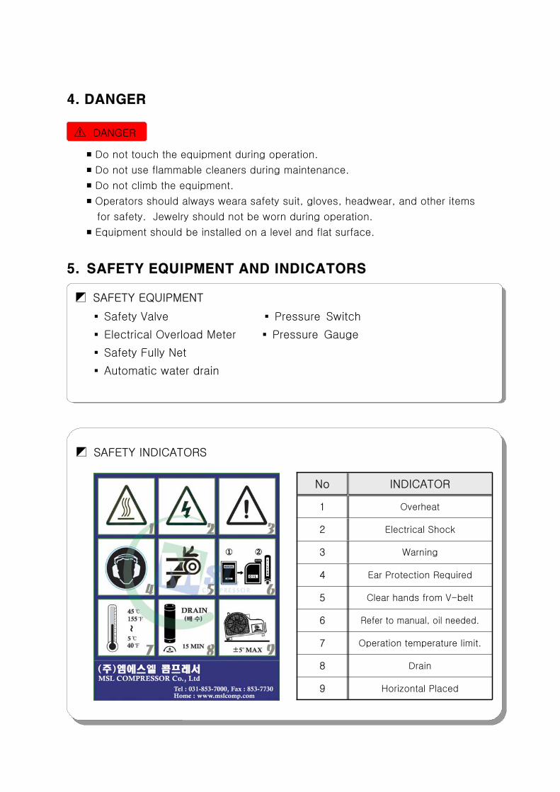
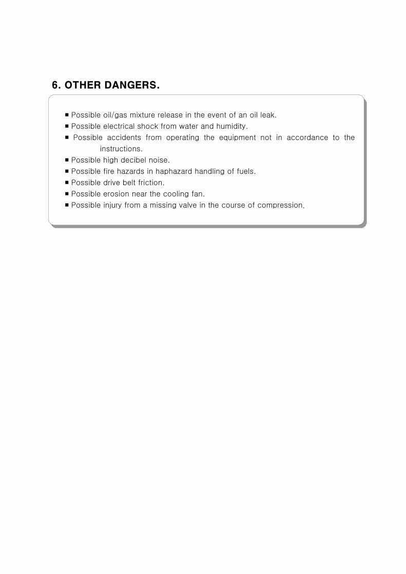
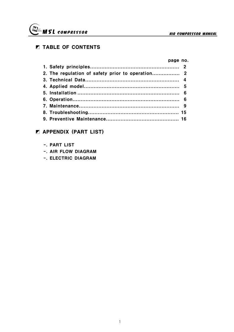
MSL COMPRESSOR AIR COMPRESSOR MANUAL
1
TABLE OF CONTENTS
page no
1 Safety principles 2
2 The regulation of safety prior to operation 2
3 Technical Data 4
4 Applied model 5
5 Installation 6
6 Operation 6
7 Maintenance 9
8 Troubleshooting 15
9 Preventive Maintenance 16
APPENDIX (PART LIST)
- PART LIST
- AIR FLOW DIAGRAM
- ELECTRIC DIAGRAM
MSL COMPRESSOR AIR COMPRESSOR MANUAL
2
1 Safety Principles
1-1 General
The user must observe safety principles to prevent accident during operation The user must pay attention to preventive maintenance table to prevent accident
1-2 Safety Principles
This machine is designed and constructed for only breathing air compressor so userhave not to use for other purposes
Only skilled-person can access to the machine during operation Machine operation can be stopped by pressing switch stop in danger situationsThe main power supply must always disconnected after operation
The power transmission belt guards should not be opened except checkingmain power supply
2 The regulation of safety prior to operation
2-1 The breathing air compressor generated so much heat that the user have to
avoid a direct ray of light
2-2 To prevent machine damage by particles and dusts you must avoid unclean area
2-3 Can be supplied enough power after confirming voltage and electric current
2-4 Use standard lubrication oil recommended by manufacturer and changes oil
periodically
2-5 Pay attention not to flow in water to the air intake port
2-6 Periodically the user drain condensation water not to impede air flow
2-7 Do not adjust pressure regulator without manufacturers agreement
2-8 Use air filter recommended by manufacturer
2-9 Use air filter recommended by manufacturer
MSL COMPRESSOR AIR COMPRESSOR MANUAL
3
Manufacturer
Company MSL COMPRESSOR Co Ltd
Address 553 Seolun-dong Pocheon-si Kyonggi-do
487-030 KOREA
TEL 82 31 541 7000 FAX 82 31 542 2999
Preparation before use
Be desirable to use the quantity of BOTTLE recommended from manufacturer
Observe the operating and relaxing time of the machine
Do the test working more five minutes in winter or after keeping it for a long time
In case of abnormal operating directly call the manufacturer
Safety Device
Pressure switch Set the pressure and Can stop the compressor in the
automatically setted pressure when the air is filled up
Overload Relay Inform the user of overload situation
Safety valve Inform the user of abnormal operating
Safety Guard Protect the machine from an obstacle
MSL COMPRESSOR AIR COMPRESSOR MANUAL
4
3 TECHNICAL DATA
MODEL NO MSF-300
DELIVERY ( min)ℓ 150
OPERATING PRESSURE ( ) 200
SAFETY VALVE SETTING PRESSURE ( ) 220
PRESSURE SWITCH SETTING PRESSURE ( ) 200
SIZE (mm) L890 x W490 x H460
WEIGHT ( ) 965
COMPRESSOR SPECIFICATION
NUMBER OF STAGES 3
NUMBER OF CYLINDERS 3
CYLINDER BORE 1 STAGE (mm) 65
CYLINDER BORE 2 STAGE (mm) 24
CYLINDER BORE 3 STAGE (mm) 13
PISTON STROKE 26
SPEED (rpm) 1750
INTERMEDIATE PRESSURE 1 STAGE ( ) 7
INTERMEDIATE PRESSURE 2 STAGE ( ) 40
COMPRESSOR BLOCK OIL CAPACITY ( )ℓ 08
AMBIENT TEMPERATURE ( ) 5 sim 45
PERMISSIBLE INCLINATION OF COMPRESSOR ( ) 5
BELT SIZE (inch) A-47
PULLEY SIZE (inch) 7
MOTOR SPECIFICATION
POWER (HP(kW)) 3(255)
SPEED (rpm) 3480
PULLEY SIZE (inch) 35
Free air delivered at bottle filling 0 to 300 plusmn5
MSL COMPRESSOR AIR COMPRESSOR MANUAL
5
4 Applied MODEL
1 SUCTION FILTER
2 CONTROL BOX
3 START SW
4 PRESSURE SW
5 OIL DRAIN
6 WHEEL
7 OIL GAUGE
8 ONOFF SW
9 AIR CLEANING FILTER
10 MOTOR
MSL COMPRESSOR AIR COMPRESSOR MANUAL
6
5 Installation
5-1 Installation area
be well-ventilated
keep out of the sun snow and rain
The place having a little effect on the weather
The flat ground
5-2 Requirements for Environmental condition
No erosion
No the inflammables
No explosive gas
Clean area
No an interference around the COMPRESSOR
5-3 Install Base
Be far at least 500mm from a wall for the COOLING amp MAINTENANCE of COMPRESSOR
Install the SUCTION FILTER in the outside
Install the engine ventilation opening and suction filter to be the maximum distance
6 Operating
6-1 The user position of the COMPRESSOR
Be located near the STOP SWITCH of COMPRESSOR
6-2 The check condition of a trial run
Check the electric current complied with the electrical specifications of motor
Check the hindrance around rotating area
Check the oil capacity
Check the filter location if it is keep out of the sun snow and rain or not
Check the tightness of bolt and the leakage of air
Check the tension of BELT
Be well acquainted with preventive maintenance check list
MSL COMPRESSOR AIR COMPRESSOR MANUAL
7
6-3 Operating Procedure
Connect plug to receptacle or connect power conductor to load side of power
disconnecting device of power supply and turn the power disconnecting device
witch ON
Connect power conductor L1 L2 and L3 to the terminal of NFBS line side and
check whether compressor turns in accordance with an arrow direction or not If its
not interchanges conduct L2 and L3 and try again(check the phase sequence)
Electric power is supplied with on of NFB(None Fused Breaker)
(If a compressor power is over 5HP then red light turns on)
Combine by turning the connector of inlet hose
FOR 150200Kg METHOD FOR 300Kg
CONNECT
DISCHARGE
VALVE AND AIR
TANK
OPEN THE
DISCHARGE VALVE
(CCW)
LOCK THE
VENTING
VALVE (CW)
CAUTION
DO NOT FASTEN
TIGHTLY
MSL COMPRESSOR AIR COMPRESSOR MANUAL
8
Turn on the DISCHARGE VALVE of compressed air
Turn off the VENTING VALVE by turning to CW direction
(Be careful of the damage of packing and air leakage)
If you select the pressure level according to users equipment and illuminated
push button switch automatically turns on at the selected level
If the illuminated push button is pressed at properly selected level then the
compressor can start
If air tank is filled up by selected pressure level the motor will be turn off
and condensing water will be drained automatically(Option)
Turn off the pressure selector switch
Turn off(close) the air tank DISCHARGE VALVE
Drain the residual compressed air by turning VENTING VALVE
(Caution Prior to disconnecting of compressed air supply connector(valve)
residual compressed air in the supplying line must be vented out)
To disconnect compressed air supply connector from air tank
Turn the compressed air supply connecting valve to CCW direction
When fill-up operation is completed turn the main power supply tooff position
and drain the condensing water by opening the hand-operated valve below filter
MSL COMPRESSOR AIR COMPRESSOR MANUAL
9
7 Maintenance
7-1 Check OIL
Check the Oil status before starting a
machine
pour the Oil when it is needed l after
checking oil status
OIL TYPE BREATHING AIR COMPRESSOR OIL
7-2 AIR SUCTION FILTER
Install the suction filter on the outside
Filter the dust of air
Use the ELEMENT after cleaning when it is
dirty
exchange ELEMENT when it is impossible to use
Using the soiled filter is not good for performance
power consumption and durability
7-3 DRAIN VALVE
Extract the water by opening the drain valve when job is finished
AUTO DRAIN VALVE is automatically opened when the COMPRESSOR is stoped
AUTO DRAIN VALVE isnt worked on condition of having a some trouble in the
SOLENOID VALVE
Be required spacial attention in winter
- Be careful of damaging the COMPRESSOR BODY and LINE by the frozen air line
- Use the hot stove to melt the frozen DRAIN VALVE
- Always operate the ELECTRIC HEATER(Option) in wintertime if there is needed
7-4 PRESSURE GAUGE
AIR PRESSURE GAUGE denotes the pressure of air serviced and OIL PRESSURE
GAUGE denotes that of LUBRICATION OIL
PRESSURE GAUGE is required of special attention for a shock not to smash
Immediately exchange on condition of being damaged
Exchange PRESSURE GAUGE to certified one
SUCTION FILTER
MSL COMPRESSOR AIR COMPRESSOR MANUAL
10
7-5 SAFETY VALVE
SAFETY VALVE protects the machine for the higher pressure than settled pressure
Must be careful of the safety valve
Must be careful of the enclosed SAFETY VALVE
Immediately exchange the damaged SAFETY VALVE
In case of changing for a safety valve you must contact with a manufacturer
Do not touch SAFETY VALVE without manufacturers authorization
Only skilled engineer can regulate safety valves setting pressure
(Caution Never exceed over 110 of rated pressure)
SAFETY VALVE TYPE-I
High pressure settingTurn the PRESSURE ADJUST SCREW to CW①after loosening the LOCK NUT②Turn the LOCK NUT to CWafter setting②the pressure watching the Pressure gauge
Low pressure setting
Turn the PRESSURE ADJUST SCREW toCCW①after loosening the LOCK NUT②Turn the LOCK NUT toCW after setting②the pressure watching the pressure gauge
SAFETY VALVE TYPE-Ⅱ
High pressure setting
Turn the PRESSURE ADJUST SCREW to① CWafter loosening the LOCK NUT②Turn the LOCK NUT toCW after adjusting②the pressure watching the pressure gauge
Low pressure settingTurn the PRESSURE ADJUST SCREW to CCW①after loosening the LOCK NUT②Turn the LOCK NUT toCW after adjusting②the pressure watching the pressure gauge
FIG5 TYPE-Ⅱ
FIG4 SAFETY VALVE
TYPE-I
MSL COMPRESSOR AIR COMPRESSOR MANUAL
11
7-6 Other safety Device
PRESSURE SWITCH
Can stop running of compressor in case of over pressured situation
CCW PRESSURE UP CW (CLOCKWISE)
CW PRESSURE DOWN CCW (COUNTER CLOCKWISE)
THERMAL RELAY
- In case of the motors being stopped by overload settle the problem and
press the reset bar then relay will run because relay is standardized by the reset
method of hand-operated
- Check the screw and Fasten it per 4 months
- Clean electromagnetic contact surface per 4 months to remove the reason of noise
- Adjust control circuits voltage to rated voltage of operating coil as exactly as
possible
7-7 MOTOR
Checking points
- Check if the motor shaft can smoothly rotate by the hand or not
- Check The Belt tension and specifications in case of exchanging it
- Check if the power supply(Voltage Frequency Phase)is conform to name plate
- Power connections are performed after verifying the conformity with that of
name plate
Check during Operation
- The operating current of continually used motor must be lower than marked
(name plate) current If the operating current is higher than marked current
check the motor
- In order to check the rotation direction and wiring operate motor under no
loading
- If the rotating direction is reversed interchange two lines among three lines
FIG6 PRESSURE SW
MSL COMPRESSOR AIR COMPRESSOR MANUAL
12
7-8 AIR CLEANING FILTER
Compressed air is purified by filter so you must change filter per every 50 hours
The filter is consist of three small size (1 2 3 step filtering) or big one size
(1 step filtering)
In case of the filter of small sizes change
A and B step filter with new one and
one step filter can be reused by cleaning
Change filter
- Turn the filter case to CCW with supplied
filter opener and resolve it
- Change new one after cleaning the inner space
- Carefully turn the filter case to CW not to
damage the o-ring
① ② ③ ④ ⑤
7-9 Checking items after operation
Must open the drain valve after compressing operation to drain compressed water
Compressor heated is needed for changing compressor oil
FIG7 AIR CLEANING
FILTER
MSL COMPRESSOR AIR COMPRESSOR MANUAL
13
7-10 Ambient conditions for preservation
Operate compressor at least 10 minutes per a week because Compressors not
running for a long time causes a failure of the machine
Keep the compressor being covered indoor where is dry and clean
Always clean the COMPRESSOR
Check the compressor periodically with maintenance table or decrease of life time
and bad performance will be caused
In case of keeping of COMPRESSOR in damp condition for a long time it needs
unloaded rotation to get compressor oil into the cylinder after removing of the filter
A compressor installed with UNLOAD EQUIPMENT needs oil lubrication after
removing of connection nipple
7-11 V-belt tension
Readjust new V-belt after the first 25 operating hours
The best tension for a belt drive is the lowest possible where the belt under
full load does not slip
A rough value for this is when the belt deflects 10 when pressed with thumb
pressure between the two pulleys
FIG8 BELT TENSION
10 mm
MSL COMPRESSOR AIR COMPRESSOR MANUAL
14
7-12 Torque sequence
Lighten valve head and cylinder boltsnuts equally in the sequence shown in
figuration
FIG9 TORQUE SEQUENCE
7-13 Tightening torque values
Unless otherwise specified in text the following torque values apply
All valve head screws require torque wrench tightening
The indicated torque values are valid for bolts in greased condition
Replace self-retaining nuts on reassembly
BOLT TYPE BOLT SIZE MAX TORQUE
HEXAGON BOLT M6 10 Nm
HEXAGON BOLT M8 25 Nm
HEXAGON BOLT M10 45 Nm
HEXAGON BOLT M12 75 Nm
HEXAGON BOLT M14 120 Nm
HEXAGON BOLT M16 200 Nm
7-14 CLEAN SEPARATOR
Remove and clean sintered filter element as follows or exchange it if completely
clogged
Remove piping connected to filter head Remove filter head along with sintered
filter element
Remove centre screw and separate sintered filter element baffle and vortex
plate from the filter head
To clean filter element use hot soapy water and blow dry with compressed air
MSL COMPRESSOR AIR COMPRESSOR MANUAL
15
8 Troubleshooting
Problem Reason Action
No rotation1Burn out of cylinderand piston
Service to manufacturer
COMPRESSOR overheat
1Failure of ventvalve2Obstructed suctionfilter
Change valve
Clean and change of filter
Fill up time is too long
1Failure of suction valve2Air line leakage3Failure of nipple4Obstructed suction filter5Failure of unload valve
Change valve Change the line with air leakage Check the nipple Clean and change of suction filter Applied lubrication oil after removement of unload nipple
Abnormal noise
1Worn down2Shortage of oil3Obstructed suction filter
Change parts Supply oil Check filter
No rotation of MOTOR
1A stoppage of electriccurrent2A break in a wire3Failure of motor starter4Bad contacting
Check the incoming wire connection Check wire disconnection Check the contact point Fasten the terminal screw Check switch
Overheated motor
1Overload2Fluctuation of Supplingvoltage and Frequency3Over voltage and voltagedips4Dad cooling
Check the rated current Check the voltage and frequency
Clean the cooling area
Reverse rotation ofmotor
1Main power supplyconnection error
Check the 3phase sequence
Can not startengine(In case of usingengine instead ofmotor)
1Discharged battery2Bad contact of electricequipment3Failure of start motor4Bad contact5Failure of generator
Fasten terminal screw fully Check switch function
Check power cable Change generator Refer to the engine manual
Electrical error
1Unexpected protectivefunction(Turn-off) of NFB
2Malfunctioning ofpressure switch
Check short-circuit Overload(Rating and setting of overcorrect protectivedevices)
Check power wire Check air line Check selected pressure Change PRESSURE SWITCH
Failure of autodrain valve
1Malfunctioning of solvalve
2Malfunctioning ofautomatic drain valve
Change SOLENOID VALVE Obstructed air line by ingress of solid bodies and liquids(Clean the line)
Check the line in the wintertime against rupture by freezing Check the wiring Ingress of solid bodies and liquids(Clean up everything) In the wintertime obstructed air line by freezing(Melt by Hot air gun)
Check air line
Failure of safetyvalve
1Ingress of external solidbodies and liquids
Clean up the ingress of solid bodies and liquids Change safety valve
AIR condensationtime is too long
1 Check the air line leakage(Verify the air line leakage under main power off afterrise up air line pressure at 150
2 Check the air leak about drain during operating conditionIf there air leakage detected change SOLENOID VALVE
3 Check the third and fourth step head and pipe NIPPLE
MSL COMPRESSOR AIR COMPRESSOR MANUAL
16
9 Preventive Maintenance
ACTIONPERIOD
TIMEHOUR DAY WEEK MONTH
QUAR-TER
HALF-YEAR YEAR
2YEAR
Clean and assembling condition
(each part of compressor)
Check CRANK CASE OIL
Check DRAIN VALVE
Check AIR leakage
Check PRESSURE GAUGE
Check PRESSURE Switch
Clean SUCTION FILTER
Check SAFETY VALVE
Check BELT tension
Change SUCTION FILTER
Check SUCTION amp DISCHARGE VALVE
CheckChange OIL FILTER ELEMENT
Change CRANK CASE OIL 50
Change DISCHARGE FILTER ELEMENT 50
Check SEPARATOR
Clean SEPARATOR
Check piston ring
MSL COMPRESSOR AIR COMPRESSOR MANUAL
P A R T L IS TMODEL MSF-300
MSL COMPRESSOR Co LtdHEAD OFFICE TEL 82 31 541 7000 FAX 82 31 542 2999HOME httpwwwmslcompcom
MSL COMPRESSOR AIR COMPRESSOR MANUAL
18
MSL COMPRESSOR AIR COMPRESSOR MANUAL
B HEAD ASSY
MSL COMPRESSOR AIR COMPRESSOR MANUAL
B HEAD ASSYKEY No PART No DESCRIPTION (Qty) NOTE
01 B-300-A-001 CRANK CASE
02 B-300-A-002 OIL GAUGE
03 B-300-F-001 SNAP RING
04 B-300-A-003 CRANK SHAFT
05 B-300-A-004 KEY
06 6306 BEARING
07 B-300-G-001 GASKET
08 B-300-A-005 BEARING COVER
09 B-300-A-006 OIL SEAL
10 6305ZZ BEARING
11 B-300-A-007 PULLEY
12 B-300-B-001 WASHER
13 B-300-B-002 BOLT
14 B-300-A-008 1 STAGE CONNECTION ROD
15 B-300-A-009 1 STAGE PISTON
16 B-300-A-010 1 STAGE PISTON PIN
17 B-300-F-002 SNAP RING
18 B-300-H-001 1 STAGE PISTON RING SET
19 B-300-G-002 GASKET
20 B-300-A-011 1 STAGE CYLINDER
21 B-300-B-003 SPRING WASHER
22 B-300-B-004 BOLT
23 B-300-G-003 GASKET
24 B-300-A-012 1 STAGE SUCTION amp DISCHARGE VALVE
25 B-300-B-005 BOLT
26 B-300-G-004 1 STAGE CYLINDER HEAD
26-1 B-300-G-004-1 BOLT
27 B-300-A-041 BOLT
28 B-300-A-042 GASKET
29 B-300-A-043 CAP NUT
MSL COMPRESSOR AIR COMPRESSOR MANUAL
B-B HEAD ASSYKEY No PART No DESCRIPTION (Qty) NOTE
30 B-300-A-014 2 STAGE CONNECTION ROD
30-1 B-300-A-014-1 3 STAGE CONNECTION ROD
31 B-300-A-015 23 STAGE PISTON PIN
32 B-300-A-016 2 STAGE PISTON
32-1 B-300-A-016-1 2 STAGE PISTON RING
33 B-300-G-005 GASKET
34 B-300-A-017 2 STAGE CYLINDER
35 B-300-G-005 GASKET
36 B-300-H-004 2 STAGE SD VALVE
37 B-300-A-018 2 STAGE CYLINDER HEAD
38 B-300-B-006 BOLT
39 B-300-A-019 3 STAGE PISTON
40 B-300-G-006 GASKET
41 B-300-A-020 3 STAGE CYLINDER
42 B-300-H-005 3 STAGE SD VALVE
43 B-300-A-021 3 STAGE CYLINDER HEAD
44 B-300-B-007 SPRING WASHER
45 B-300-B-008 BOLT
46 B-300-A-035 3 STAGE SPARE PISTON
47 B-300-A-036 2 STAGE SLEEVE
48 B-300-A-037 3 STAGE SLEEVE
49 HK3516 BEARING
50 HK1616B BEARING
51 B-300-A-038 2 STAGE VALVE BODY
52 B-300-A-039 3 STAGE VALVE BODY
53 B-300-A-040 SLEEVE HEAD GUARD
MSL COMPRESSOR AIR COMPRESSOR MANUAL
C 1 2 STAGE FILTER SETS
MSL COMPRESSOR AIR COMPRESSOR MANUAL
C 12 STAGE FILTER SETSKEY No PART No DESCRIPTION (Qty) NOTE
01 B-300-A-028 BODY
02 B-300-A-029 1 STAGE FILTER DOWN CAP
03 B-300-F-005 O-RING
04 B-300-A-030 1 STAGE FILTER ELEMENT
05 B-300-H-015 1 STAGE FILTER ELEMENT SET
06 B-300-H-016 1 STAGE FILTER DOWN CAP SET
07 B-300-F-006 O-RING
08 B-300-B-017 ALLEN SCREW
09 B-300-B-018 WASHER
10 B-300-B-019 SPRING WASHER
11 B-300-A-031 DRAIN VALVE
12 B-300-A-032 2 STAGE FILTER DOWN CAP
13 B-300-H-017 2 STAGE FILTER DOWN CAP SET
14 B-300-A-033 2 STAGE FILTER ELEMENT
15 B-300-H-018 2 STAGE FILTER ELEMENT SET
16 B-300-B-020 ALLEN SCREW
MSL COMPRESSOR AIR COMPRESSOR MANUAL
D AIR COOLING SYSTEM
MSL COMPRESSOR AIR COMPRESSOR MANUAL
D AIR COOLING SYSTEMKEY No PART No DESCRIPTION (Qty) NOTE
01 B-300-H-001 1 STAGE INTER COOLER SET 4
02 B-300-H-002 2 STAGE INTER COOLER SET 2
03 B-300-H-003 AFTER COOLER SET 2
04 B-300-H-004 AIR CONNECTING PIPE SET 4
05 B-300-H-005 CONNECTOR 7
06 B-300-H-006 CONNECTOR 2
07 B-300-H-007 CONNECTOR 2
08 B-300-B-008 SAFETY VALVE 1
09 B-300-B-009 CONNECTOR 1
MSL COMPRESSOR AIR COMPRESSOR MANUAL
E SEPARATOR SET
MSL COMPRESSOR AIR COMPRESSOR MANUAL
E SEPARATOR SETKEY No PART No DESCRIPTION (Qty) NOTE
01 B-300-A-023 BODY
02 B-300-A-024 SEPARATOR DOWN CAP
03 B-300-F-003 O-RING
04 B-300-H-013 SEPARATOR DOWN CAP SET
05 B-300-A-024 DRAIN VALVE
06 B-300-B-013 ALLEN SCREW
07 B-300-B-014 WASHER
08 B-300-B-015 SPRING WASHER
09 B-300-A-025 BOTTOM COVER
10 B-300-A-026 BEADS
11 B-300-A-027 TOP COVER
12 B-300-F-004 SPRING
13 B-300-H-014 ELEMENT SET
14 B-300-B-016 ALLEN SCREW
MSL COMPRESSOR AIR COMPRESSOR MANUAL
MSL COMPRESSOR AIR COMPRESSOR MANUAL
MSL COMPRESSOR AIR COMPRESSOR MANUAL
MSL COMPRESSOR AIR COMPRESSOR MANUAL
MEMO
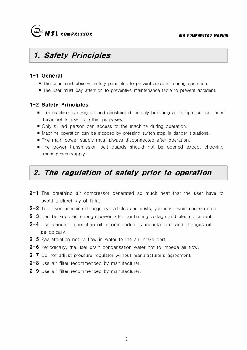
MSL COMPRESSOR AIR COMPRESSOR MANUAL
2
1 Safety Principles
1-1 General
The user must observe safety principles to prevent accident during operation The user must pay attention to preventive maintenance table to prevent accident
1-2 Safety Principles
This machine is designed and constructed for only breathing air compressor so userhave not to use for other purposes
Only skilled-person can access to the machine during operation Machine operation can be stopped by pressing switch stop in danger situationsThe main power supply must always disconnected after operation
The power transmission belt guards should not be opened except checkingmain power supply
2 The regulation of safety prior to operation
2-1 The breathing air compressor generated so much heat that the user have to
avoid a direct ray of light
2-2 To prevent machine damage by particles and dusts you must avoid unclean area
2-3 Can be supplied enough power after confirming voltage and electric current
2-4 Use standard lubrication oil recommended by manufacturer and changes oil
periodically
2-5 Pay attention not to flow in water to the air intake port
2-6 Periodically the user drain condensation water not to impede air flow
2-7 Do not adjust pressure regulator without manufacturers agreement
2-8 Use air filter recommended by manufacturer
2-9 Use air filter recommended by manufacturer
MSL COMPRESSOR AIR COMPRESSOR MANUAL
3
Manufacturer
Company MSL COMPRESSOR Co Ltd
Address 553 Seolun-dong Pocheon-si Kyonggi-do
487-030 KOREA
TEL 82 31 541 7000 FAX 82 31 542 2999
Preparation before use
Be desirable to use the quantity of BOTTLE recommended from manufacturer
Observe the operating and relaxing time of the machine
Do the test working more five minutes in winter or after keeping it for a long time
In case of abnormal operating directly call the manufacturer
Safety Device
Pressure switch Set the pressure and Can stop the compressor in the
automatically setted pressure when the air is filled up
Overload Relay Inform the user of overload situation
Safety valve Inform the user of abnormal operating
Safety Guard Protect the machine from an obstacle
MSL COMPRESSOR AIR COMPRESSOR MANUAL
4
3 TECHNICAL DATA
MODEL NO MSF-300
DELIVERY ( min)ℓ 150
OPERATING PRESSURE ( ) 200
SAFETY VALVE SETTING PRESSURE ( ) 220
PRESSURE SWITCH SETTING PRESSURE ( ) 200
SIZE (mm) L890 x W490 x H460
WEIGHT ( ) 965
COMPRESSOR SPECIFICATION
NUMBER OF STAGES 3
NUMBER OF CYLINDERS 3
CYLINDER BORE 1 STAGE (mm) 65
CYLINDER BORE 2 STAGE (mm) 24
CYLINDER BORE 3 STAGE (mm) 13
PISTON STROKE 26
SPEED (rpm) 1750
INTERMEDIATE PRESSURE 1 STAGE ( ) 7
INTERMEDIATE PRESSURE 2 STAGE ( ) 40
COMPRESSOR BLOCK OIL CAPACITY ( )ℓ 08
AMBIENT TEMPERATURE ( ) 5 sim 45
PERMISSIBLE INCLINATION OF COMPRESSOR ( ) 5
BELT SIZE (inch) A-47
PULLEY SIZE (inch) 7
MOTOR SPECIFICATION
POWER (HP(kW)) 3(255)
SPEED (rpm) 3480
PULLEY SIZE (inch) 35
Free air delivered at bottle filling 0 to 300 plusmn5
MSL COMPRESSOR AIR COMPRESSOR MANUAL
5
4 Applied MODEL
1 SUCTION FILTER
2 CONTROL BOX
3 START SW
4 PRESSURE SW
5 OIL DRAIN
6 WHEEL
7 OIL GAUGE
8 ONOFF SW
9 AIR CLEANING FILTER
10 MOTOR
MSL COMPRESSOR AIR COMPRESSOR MANUAL
6
5 Installation
5-1 Installation area
be well-ventilated
keep out of the sun snow and rain
The place having a little effect on the weather
The flat ground
5-2 Requirements for Environmental condition
No erosion
No the inflammables
No explosive gas
Clean area
No an interference around the COMPRESSOR
5-3 Install Base
Be far at least 500mm from a wall for the COOLING amp MAINTENANCE of COMPRESSOR
Install the SUCTION FILTER in the outside
Install the engine ventilation opening and suction filter to be the maximum distance
6 Operating
6-1 The user position of the COMPRESSOR
Be located near the STOP SWITCH of COMPRESSOR
6-2 The check condition of a trial run
Check the electric current complied with the electrical specifications of motor
Check the hindrance around rotating area
Check the oil capacity
Check the filter location if it is keep out of the sun snow and rain or not
Check the tightness of bolt and the leakage of air
Check the tension of BELT
Be well acquainted with preventive maintenance check list
MSL COMPRESSOR AIR COMPRESSOR MANUAL
7
6-3 Operating Procedure
Connect plug to receptacle or connect power conductor to load side of power
disconnecting device of power supply and turn the power disconnecting device
witch ON
Connect power conductor L1 L2 and L3 to the terminal of NFBS line side and
check whether compressor turns in accordance with an arrow direction or not If its
not interchanges conduct L2 and L3 and try again(check the phase sequence)
Electric power is supplied with on of NFB(None Fused Breaker)
(If a compressor power is over 5HP then red light turns on)
Combine by turning the connector of inlet hose
FOR 150200Kg METHOD FOR 300Kg
CONNECT
DISCHARGE
VALVE AND AIR
TANK
OPEN THE
DISCHARGE VALVE
(CCW)
LOCK THE
VENTING
VALVE (CW)
CAUTION
DO NOT FASTEN
TIGHTLY
MSL COMPRESSOR AIR COMPRESSOR MANUAL
8
Turn on the DISCHARGE VALVE of compressed air
Turn off the VENTING VALVE by turning to CW direction
(Be careful of the damage of packing and air leakage)
If you select the pressure level according to users equipment and illuminated
push button switch automatically turns on at the selected level
If the illuminated push button is pressed at properly selected level then the
compressor can start
If air tank is filled up by selected pressure level the motor will be turn off
and condensing water will be drained automatically(Option)
Turn off the pressure selector switch
Turn off(close) the air tank DISCHARGE VALVE
Drain the residual compressed air by turning VENTING VALVE
(Caution Prior to disconnecting of compressed air supply connector(valve)
residual compressed air in the supplying line must be vented out)
To disconnect compressed air supply connector from air tank
Turn the compressed air supply connecting valve to CCW direction
When fill-up operation is completed turn the main power supply tooff position
and drain the condensing water by opening the hand-operated valve below filter
MSL COMPRESSOR AIR COMPRESSOR MANUAL
9
7 Maintenance
7-1 Check OIL
Check the Oil status before starting a
machine
pour the Oil when it is needed l after
checking oil status
OIL TYPE BREATHING AIR COMPRESSOR OIL
7-2 AIR SUCTION FILTER
Install the suction filter on the outside
Filter the dust of air
Use the ELEMENT after cleaning when it is
dirty
exchange ELEMENT when it is impossible to use
Using the soiled filter is not good for performance
power consumption and durability
7-3 DRAIN VALVE
Extract the water by opening the drain valve when job is finished
AUTO DRAIN VALVE is automatically opened when the COMPRESSOR is stoped
AUTO DRAIN VALVE isnt worked on condition of having a some trouble in the
SOLENOID VALVE
Be required spacial attention in winter
- Be careful of damaging the COMPRESSOR BODY and LINE by the frozen air line
- Use the hot stove to melt the frozen DRAIN VALVE
- Always operate the ELECTRIC HEATER(Option) in wintertime if there is needed
7-4 PRESSURE GAUGE
AIR PRESSURE GAUGE denotes the pressure of air serviced and OIL PRESSURE
GAUGE denotes that of LUBRICATION OIL
PRESSURE GAUGE is required of special attention for a shock not to smash
Immediately exchange on condition of being damaged
Exchange PRESSURE GAUGE to certified one
SUCTION FILTER
MSL COMPRESSOR AIR COMPRESSOR MANUAL
10
7-5 SAFETY VALVE
SAFETY VALVE protects the machine for the higher pressure than settled pressure
Must be careful of the safety valve
Must be careful of the enclosed SAFETY VALVE
Immediately exchange the damaged SAFETY VALVE
In case of changing for a safety valve you must contact with a manufacturer
Do not touch SAFETY VALVE without manufacturers authorization
Only skilled engineer can regulate safety valves setting pressure
(Caution Never exceed over 110 of rated pressure)
SAFETY VALVE TYPE-I
High pressure settingTurn the PRESSURE ADJUST SCREW to CW①after loosening the LOCK NUT②Turn the LOCK NUT to CWafter setting②the pressure watching the Pressure gauge
Low pressure setting
Turn the PRESSURE ADJUST SCREW toCCW①after loosening the LOCK NUT②Turn the LOCK NUT toCW after setting②the pressure watching the pressure gauge
SAFETY VALVE TYPE-Ⅱ
High pressure setting
Turn the PRESSURE ADJUST SCREW to① CWafter loosening the LOCK NUT②Turn the LOCK NUT toCW after adjusting②the pressure watching the pressure gauge
Low pressure settingTurn the PRESSURE ADJUST SCREW to CCW①after loosening the LOCK NUT②Turn the LOCK NUT toCW after adjusting②the pressure watching the pressure gauge
FIG5 TYPE-Ⅱ
FIG4 SAFETY VALVE
TYPE-I
MSL COMPRESSOR AIR COMPRESSOR MANUAL
11
7-6 Other safety Device
PRESSURE SWITCH
Can stop running of compressor in case of over pressured situation
CCW PRESSURE UP CW (CLOCKWISE)
CW PRESSURE DOWN CCW (COUNTER CLOCKWISE)
THERMAL RELAY
- In case of the motors being stopped by overload settle the problem and
press the reset bar then relay will run because relay is standardized by the reset
method of hand-operated
- Check the screw and Fasten it per 4 months
- Clean electromagnetic contact surface per 4 months to remove the reason of noise
- Adjust control circuits voltage to rated voltage of operating coil as exactly as
possible
7-7 MOTOR
Checking points
- Check if the motor shaft can smoothly rotate by the hand or not
- Check The Belt tension and specifications in case of exchanging it
- Check if the power supply(Voltage Frequency Phase)is conform to name plate
- Power connections are performed after verifying the conformity with that of
name plate
Check during Operation
- The operating current of continually used motor must be lower than marked
(name plate) current If the operating current is higher than marked current
check the motor
- In order to check the rotation direction and wiring operate motor under no
loading
- If the rotating direction is reversed interchange two lines among three lines
FIG6 PRESSURE SW
MSL COMPRESSOR AIR COMPRESSOR MANUAL
12
7-8 AIR CLEANING FILTER
Compressed air is purified by filter so you must change filter per every 50 hours
The filter is consist of three small size (1 2 3 step filtering) or big one size
(1 step filtering)
In case of the filter of small sizes change
A and B step filter with new one and
one step filter can be reused by cleaning
Change filter
- Turn the filter case to CCW with supplied
filter opener and resolve it
- Change new one after cleaning the inner space
- Carefully turn the filter case to CW not to
damage the o-ring
① ② ③ ④ ⑤
7-9 Checking items after operation
Must open the drain valve after compressing operation to drain compressed water
Compressor heated is needed for changing compressor oil
FIG7 AIR CLEANING
FILTER
MSL COMPRESSOR AIR COMPRESSOR MANUAL
13
7-10 Ambient conditions for preservation
Operate compressor at least 10 minutes per a week because Compressors not
running for a long time causes a failure of the machine
Keep the compressor being covered indoor where is dry and clean
Always clean the COMPRESSOR
Check the compressor periodically with maintenance table or decrease of life time
and bad performance will be caused
In case of keeping of COMPRESSOR in damp condition for a long time it needs
unloaded rotation to get compressor oil into the cylinder after removing of the filter
A compressor installed with UNLOAD EQUIPMENT needs oil lubrication after
removing of connection nipple
7-11 V-belt tension
Readjust new V-belt after the first 25 operating hours
The best tension for a belt drive is the lowest possible where the belt under
full load does not slip
A rough value for this is when the belt deflects 10 when pressed with thumb
pressure between the two pulleys
FIG8 BELT TENSION
10 mm
MSL COMPRESSOR AIR COMPRESSOR MANUAL
14
7-12 Torque sequence
Lighten valve head and cylinder boltsnuts equally in the sequence shown in
figuration
FIG9 TORQUE SEQUENCE
7-13 Tightening torque values
Unless otherwise specified in text the following torque values apply
All valve head screws require torque wrench tightening
The indicated torque values are valid for bolts in greased condition
Replace self-retaining nuts on reassembly
BOLT TYPE BOLT SIZE MAX TORQUE
HEXAGON BOLT M6 10 Nm
HEXAGON BOLT M8 25 Nm
HEXAGON BOLT M10 45 Nm
HEXAGON BOLT M12 75 Nm
HEXAGON BOLT M14 120 Nm
HEXAGON BOLT M16 200 Nm
7-14 CLEAN SEPARATOR
Remove and clean sintered filter element as follows or exchange it if completely
clogged
Remove piping connected to filter head Remove filter head along with sintered
filter element
Remove centre screw and separate sintered filter element baffle and vortex
plate from the filter head
To clean filter element use hot soapy water and blow dry with compressed air
MSL COMPRESSOR AIR COMPRESSOR MANUAL
15
8 Troubleshooting
Problem Reason Action
No rotation1Burn out of cylinderand piston
Service to manufacturer
COMPRESSOR overheat
1Failure of ventvalve2Obstructed suctionfilter
Change valve
Clean and change of filter
Fill up time is too long
1Failure of suction valve2Air line leakage3Failure of nipple4Obstructed suction filter5Failure of unload valve
Change valve Change the line with air leakage Check the nipple Clean and change of suction filter Applied lubrication oil after removement of unload nipple
Abnormal noise
1Worn down2Shortage of oil3Obstructed suction filter
Change parts Supply oil Check filter
No rotation of MOTOR
1A stoppage of electriccurrent2A break in a wire3Failure of motor starter4Bad contacting
Check the incoming wire connection Check wire disconnection Check the contact point Fasten the terminal screw Check switch
Overheated motor
1Overload2Fluctuation of Supplingvoltage and Frequency3Over voltage and voltagedips4Dad cooling
Check the rated current Check the voltage and frequency
Clean the cooling area
Reverse rotation ofmotor
1Main power supplyconnection error
Check the 3phase sequence
Can not startengine(In case of usingengine instead ofmotor)
1Discharged battery2Bad contact of electricequipment3Failure of start motor4Bad contact5Failure of generator
Fasten terminal screw fully Check switch function
Check power cable Change generator Refer to the engine manual
Electrical error
1Unexpected protectivefunction(Turn-off) of NFB
2Malfunctioning ofpressure switch
Check short-circuit Overload(Rating and setting of overcorrect protectivedevices)
Check power wire Check air line Check selected pressure Change PRESSURE SWITCH
Failure of autodrain valve
1Malfunctioning of solvalve
2Malfunctioning ofautomatic drain valve
Change SOLENOID VALVE Obstructed air line by ingress of solid bodies and liquids(Clean the line)
Check the line in the wintertime against rupture by freezing Check the wiring Ingress of solid bodies and liquids(Clean up everything) In the wintertime obstructed air line by freezing(Melt by Hot air gun)
Check air line
Failure of safetyvalve
1Ingress of external solidbodies and liquids
Clean up the ingress of solid bodies and liquids Change safety valve
AIR condensationtime is too long
1 Check the air line leakage(Verify the air line leakage under main power off afterrise up air line pressure at 150
2 Check the air leak about drain during operating conditionIf there air leakage detected change SOLENOID VALVE
3 Check the third and fourth step head and pipe NIPPLE
MSL COMPRESSOR AIR COMPRESSOR MANUAL
16
9 Preventive Maintenance
ACTIONPERIOD
TIMEHOUR DAY WEEK MONTH
QUAR-TER
HALF-YEAR YEAR
2YEAR
Clean and assembling condition
(each part of compressor)
Check CRANK CASE OIL
Check DRAIN VALVE
Check AIR leakage
Check PRESSURE GAUGE
Check PRESSURE Switch
Clean SUCTION FILTER
Check SAFETY VALVE
Check BELT tension
Change SUCTION FILTER
Check SUCTION amp DISCHARGE VALVE
CheckChange OIL FILTER ELEMENT
Change CRANK CASE OIL 50
Change DISCHARGE FILTER ELEMENT 50
Check SEPARATOR
Clean SEPARATOR
Check piston ring
MSL COMPRESSOR AIR COMPRESSOR MANUAL
P A R T L IS TMODEL MSF-300
MSL COMPRESSOR Co LtdHEAD OFFICE TEL 82 31 541 7000 FAX 82 31 542 2999HOME httpwwwmslcompcom
MSL COMPRESSOR AIR COMPRESSOR MANUAL
18
MSL COMPRESSOR AIR COMPRESSOR MANUAL
B HEAD ASSY
MSL COMPRESSOR AIR COMPRESSOR MANUAL
B HEAD ASSYKEY No PART No DESCRIPTION (Qty) NOTE
01 B-300-A-001 CRANK CASE
02 B-300-A-002 OIL GAUGE
03 B-300-F-001 SNAP RING
04 B-300-A-003 CRANK SHAFT
05 B-300-A-004 KEY
06 6306 BEARING
07 B-300-G-001 GASKET
08 B-300-A-005 BEARING COVER
09 B-300-A-006 OIL SEAL
10 6305ZZ BEARING
11 B-300-A-007 PULLEY
12 B-300-B-001 WASHER
13 B-300-B-002 BOLT
14 B-300-A-008 1 STAGE CONNECTION ROD
15 B-300-A-009 1 STAGE PISTON
16 B-300-A-010 1 STAGE PISTON PIN
17 B-300-F-002 SNAP RING
18 B-300-H-001 1 STAGE PISTON RING SET
19 B-300-G-002 GASKET
20 B-300-A-011 1 STAGE CYLINDER
21 B-300-B-003 SPRING WASHER
22 B-300-B-004 BOLT
23 B-300-G-003 GASKET
24 B-300-A-012 1 STAGE SUCTION amp DISCHARGE VALVE
25 B-300-B-005 BOLT
26 B-300-G-004 1 STAGE CYLINDER HEAD
26-1 B-300-G-004-1 BOLT
27 B-300-A-041 BOLT
28 B-300-A-042 GASKET
29 B-300-A-043 CAP NUT
MSL COMPRESSOR AIR COMPRESSOR MANUAL
B-B HEAD ASSYKEY No PART No DESCRIPTION (Qty) NOTE
30 B-300-A-014 2 STAGE CONNECTION ROD
30-1 B-300-A-014-1 3 STAGE CONNECTION ROD
31 B-300-A-015 23 STAGE PISTON PIN
32 B-300-A-016 2 STAGE PISTON
32-1 B-300-A-016-1 2 STAGE PISTON RING
33 B-300-G-005 GASKET
34 B-300-A-017 2 STAGE CYLINDER
35 B-300-G-005 GASKET
36 B-300-H-004 2 STAGE SD VALVE
37 B-300-A-018 2 STAGE CYLINDER HEAD
38 B-300-B-006 BOLT
39 B-300-A-019 3 STAGE PISTON
40 B-300-G-006 GASKET
41 B-300-A-020 3 STAGE CYLINDER
42 B-300-H-005 3 STAGE SD VALVE
43 B-300-A-021 3 STAGE CYLINDER HEAD
44 B-300-B-007 SPRING WASHER
45 B-300-B-008 BOLT
46 B-300-A-035 3 STAGE SPARE PISTON
47 B-300-A-036 2 STAGE SLEEVE
48 B-300-A-037 3 STAGE SLEEVE
49 HK3516 BEARING
50 HK1616B BEARING
51 B-300-A-038 2 STAGE VALVE BODY
52 B-300-A-039 3 STAGE VALVE BODY
53 B-300-A-040 SLEEVE HEAD GUARD
MSL COMPRESSOR AIR COMPRESSOR MANUAL
C 1 2 STAGE FILTER SETS
MSL COMPRESSOR AIR COMPRESSOR MANUAL
C 12 STAGE FILTER SETSKEY No PART No DESCRIPTION (Qty) NOTE
01 B-300-A-028 BODY
02 B-300-A-029 1 STAGE FILTER DOWN CAP
03 B-300-F-005 O-RING
04 B-300-A-030 1 STAGE FILTER ELEMENT
05 B-300-H-015 1 STAGE FILTER ELEMENT SET
06 B-300-H-016 1 STAGE FILTER DOWN CAP SET
07 B-300-F-006 O-RING
08 B-300-B-017 ALLEN SCREW
09 B-300-B-018 WASHER
10 B-300-B-019 SPRING WASHER
11 B-300-A-031 DRAIN VALVE
12 B-300-A-032 2 STAGE FILTER DOWN CAP
13 B-300-H-017 2 STAGE FILTER DOWN CAP SET
14 B-300-A-033 2 STAGE FILTER ELEMENT
15 B-300-H-018 2 STAGE FILTER ELEMENT SET
16 B-300-B-020 ALLEN SCREW
MSL COMPRESSOR AIR COMPRESSOR MANUAL
D AIR COOLING SYSTEM
MSL COMPRESSOR AIR COMPRESSOR MANUAL
D AIR COOLING SYSTEMKEY No PART No DESCRIPTION (Qty) NOTE
01 B-300-H-001 1 STAGE INTER COOLER SET 4
02 B-300-H-002 2 STAGE INTER COOLER SET 2
03 B-300-H-003 AFTER COOLER SET 2
04 B-300-H-004 AIR CONNECTING PIPE SET 4
05 B-300-H-005 CONNECTOR 7
06 B-300-H-006 CONNECTOR 2
07 B-300-H-007 CONNECTOR 2
08 B-300-B-008 SAFETY VALVE 1
09 B-300-B-009 CONNECTOR 1
MSL COMPRESSOR AIR COMPRESSOR MANUAL
E SEPARATOR SET
MSL COMPRESSOR AIR COMPRESSOR MANUAL
E SEPARATOR SETKEY No PART No DESCRIPTION (Qty) NOTE
01 B-300-A-023 BODY
02 B-300-A-024 SEPARATOR DOWN CAP
03 B-300-F-003 O-RING
04 B-300-H-013 SEPARATOR DOWN CAP SET
05 B-300-A-024 DRAIN VALVE
06 B-300-B-013 ALLEN SCREW
07 B-300-B-014 WASHER
08 B-300-B-015 SPRING WASHER
09 B-300-A-025 BOTTOM COVER
10 B-300-A-026 BEADS
11 B-300-A-027 TOP COVER
12 B-300-F-004 SPRING
13 B-300-H-014 ELEMENT SET
14 B-300-B-016 ALLEN SCREW
MSL COMPRESSOR AIR COMPRESSOR MANUAL
MSL COMPRESSOR AIR COMPRESSOR MANUAL
MSL COMPRESSOR AIR COMPRESSOR MANUAL
MSL COMPRESSOR AIR COMPRESSOR MANUAL
MEMO
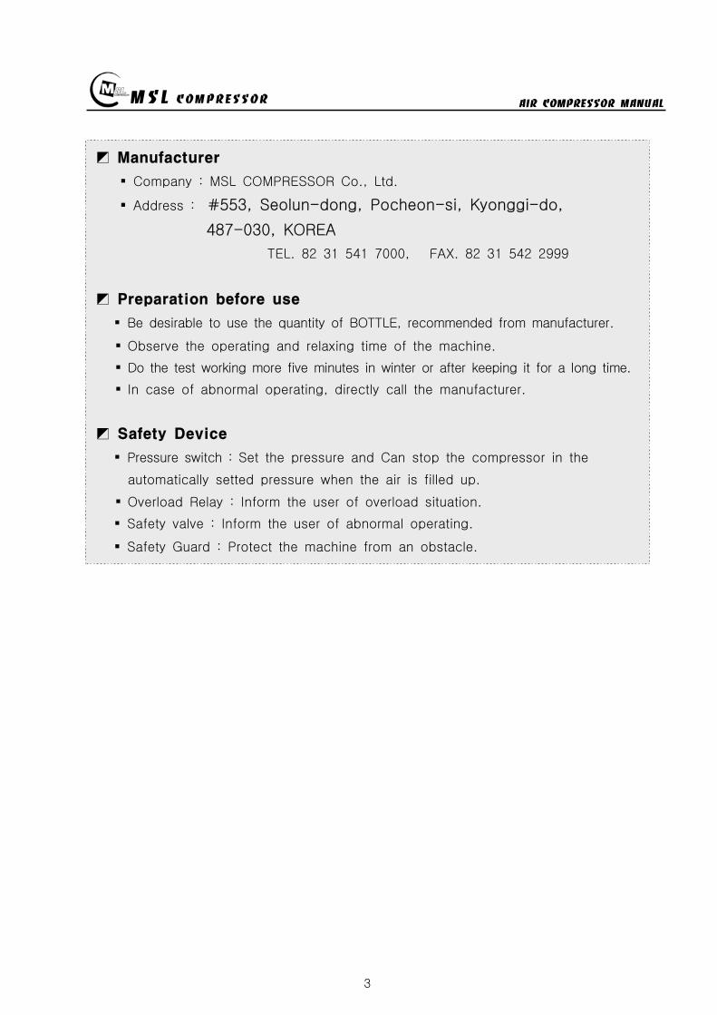
MSL COMPRESSOR AIR COMPRESSOR MANUAL
3
Manufacturer
Company MSL COMPRESSOR Co Ltd
Address 553 Seolun-dong Pocheon-si Kyonggi-do
487-030 KOREA
TEL 82 31 541 7000 FAX 82 31 542 2999
Preparation before use
Be desirable to use the quantity of BOTTLE recommended from manufacturer
Observe the operating and relaxing time of the machine
Do the test working more five minutes in winter or after keeping it for a long time
In case of abnormal operating directly call the manufacturer
Safety Device
Pressure switch Set the pressure and Can stop the compressor in the
automatically setted pressure when the air is filled up
Overload Relay Inform the user of overload situation
Safety valve Inform the user of abnormal operating
Safety Guard Protect the machine from an obstacle
MSL COMPRESSOR AIR COMPRESSOR MANUAL
4
3 TECHNICAL DATA
MODEL NO MSF-300
DELIVERY ( min)ℓ 150
OPERATING PRESSURE ( ) 200
SAFETY VALVE SETTING PRESSURE ( ) 220
PRESSURE SWITCH SETTING PRESSURE ( ) 200
SIZE (mm) L890 x W490 x H460
WEIGHT ( ) 965
COMPRESSOR SPECIFICATION
NUMBER OF STAGES 3
NUMBER OF CYLINDERS 3
CYLINDER BORE 1 STAGE (mm) 65
CYLINDER BORE 2 STAGE (mm) 24
CYLINDER BORE 3 STAGE (mm) 13
PISTON STROKE 26
SPEED (rpm) 1750
INTERMEDIATE PRESSURE 1 STAGE ( ) 7
INTERMEDIATE PRESSURE 2 STAGE ( ) 40
COMPRESSOR BLOCK OIL CAPACITY ( )ℓ 08
AMBIENT TEMPERATURE ( ) 5 sim 45
PERMISSIBLE INCLINATION OF COMPRESSOR ( ) 5
BELT SIZE (inch) A-47
PULLEY SIZE (inch) 7
MOTOR SPECIFICATION
POWER (HP(kW)) 3(255)
SPEED (rpm) 3480
PULLEY SIZE (inch) 35
Free air delivered at bottle filling 0 to 300 plusmn5
MSL COMPRESSOR AIR COMPRESSOR MANUAL
5
4 Applied MODEL
1 SUCTION FILTER
2 CONTROL BOX
3 START SW
4 PRESSURE SW
5 OIL DRAIN
6 WHEEL
7 OIL GAUGE
8 ONOFF SW
9 AIR CLEANING FILTER
10 MOTOR
MSL COMPRESSOR AIR COMPRESSOR MANUAL
6
5 Installation
5-1 Installation area
be well-ventilated
keep out of the sun snow and rain
The place having a little effect on the weather
The flat ground
5-2 Requirements for Environmental condition
No erosion
No the inflammables
No explosive gas
Clean area
No an interference around the COMPRESSOR
5-3 Install Base
Be far at least 500mm from a wall for the COOLING amp MAINTENANCE of COMPRESSOR
Install the SUCTION FILTER in the outside
Install the engine ventilation opening and suction filter to be the maximum distance
6 Operating
6-1 The user position of the COMPRESSOR
Be located near the STOP SWITCH of COMPRESSOR
6-2 The check condition of a trial run
Check the electric current complied with the electrical specifications of motor
Check the hindrance around rotating area
Check the oil capacity
Check the filter location if it is keep out of the sun snow and rain or not
Check the tightness of bolt and the leakage of air
Check the tension of BELT
Be well acquainted with preventive maintenance check list
MSL COMPRESSOR AIR COMPRESSOR MANUAL
7
6-3 Operating Procedure
Connect plug to receptacle or connect power conductor to load side of power
disconnecting device of power supply and turn the power disconnecting device
witch ON
Connect power conductor L1 L2 and L3 to the terminal of NFBS line side and
check whether compressor turns in accordance with an arrow direction or not If its
not interchanges conduct L2 and L3 and try again(check the phase sequence)
Electric power is supplied with on of NFB(None Fused Breaker)
(If a compressor power is over 5HP then red light turns on)
Combine by turning the connector of inlet hose
FOR 150200Kg METHOD FOR 300Kg
CONNECT
DISCHARGE
VALVE AND AIR
TANK
OPEN THE
DISCHARGE VALVE
(CCW)
LOCK THE
VENTING
VALVE (CW)
CAUTION
DO NOT FASTEN
TIGHTLY
MSL COMPRESSOR AIR COMPRESSOR MANUAL
8
Turn on the DISCHARGE VALVE of compressed air
Turn off the VENTING VALVE by turning to CW direction
(Be careful of the damage of packing and air leakage)
If you select the pressure level according to users equipment and illuminated
push button switch automatically turns on at the selected level
If the illuminated push button is pressed at properly selected level then the
compressor can start
If air tank is filled up by selected pressure level the motor will be turn off
and condensing water will be drained automatically(Option)
Turn off the pressure selector switch
Turn off(close) the air tank DISCHARGE VALVE
Drain the residual compressed air by turning VENTING VALVE
(Caution Prior to disconnecting of compressed air supply connector(valve)
residual compressed air in the supplying line must be vented out)
To disconnect compressed air supply connector from air tank
Turn the compressed air supply connecting valve to CCW direction
When fill-up operation is completed turn the main power supply tooff position
and drain the condensing water by opening the hand-operated valve below filter
MSL COMPRESSOR AIR COMPRESSOR MANUAL
9
7 Maintenance
7-1 Check OIL
Check the Oil status before starting a
machine
pour the Oil when it is needed l after
checking oil status
OIL TYPE BREATHING AIR COMPRESSOR OIL
7-2 AIR SUCTION FILTER
Install the suction filter on the outside
Filter the dust of air
Use the ELEMENT after cleaning when it is
dirty
exchange ELEMENT when it is impossible to use
Using the soiled filter is not good for performance
power consumption and durability
7-3 DRAIN VALVE
Extract the water by opening the drain valve when job is finished
AUTO DRAIN VALVE is automatically opened when the COMPRESSOR is stoped
AUTO DRAIN VALVE isnt worked on condition of having a some trouble in the
SOLENOID VALVE
Be required spacial attention in winter
- Be careful of damaging the COMPRESSOR BODY and LINE by the frozen air line
- Use the hot stove to melt the frozen DRAIN VALVE
- Always operate the ELECTRIC HEATER(Option) in wintertime if there is needed
7-4 PRESSURE GAUGE
AIR PRESSURE GAUGE denotes the pressure of air serviced and OIL PRESSURE
GAUGE denotes that of LUBRICATION OIL
PRESSURE GAUGE is required of special attention for a shock not to smash
Immediately exchange on condition of being damaged
Exchange PRESSURE GAUGE to certified one
SUCTION FILTER
MSL COMPRESSOR AIR COMPRESSOR MANUAL
10
7-5 SAFETY VALVE
SAFETY VALVE protects the machine for the higher pressure than settled pressure
Must be careful of the safety valve
Must be careful of the enclosed SAFETY VALVE
Immediately exchange the damaged SAFETY VALVE
In case of changing for a safety valve you must contact with a manufacturer
Do not touch SAFETY VALVE without manufacturers authorization
Only skilled engineer can regulate safety valves setting pressure
(Caution Never exceed over 110 of rated pressure)
SAFETY VALVE TYPE-I
High pressure settingTurn the PRESSURE ADJUST SCREW to CW①after loosening the LOCK NUT②Turn the LOCK NUT to CWafter setting②the pressure watching the Pressure gauge
Low pressure setting
Turn the PRESSURE ADJUST SCREW toCCW①after loosening the LOCK NUT②Turn the LOCK NUT toCW after setting②the pressure watching the pressure gauge
SAFETY VALVE TYPE-Ⅱ
High pressure setting
Turn the PRESSURE ADJUST SCREW to① CWafter loosening the LOCK NUT②Turn the LOCK NUT toCW after adjusting②the pressure watching the pressure gauge
Low pressure settingTurn the PRESSURE ADJUST SCREW to CCW①after loosening the LOCK NUT②Turn the LOCK NUT toCW after adjusting②the pressure watching the pressure gauge
FIG5 TYPE-Ⅱ
FIG4 SAFETY VALVE
TYPE-I
MSL COMPRESSOR AIR COMPRESSOR MANUAL
11
7-6 Other safety Device
PRESSURE SWITCH
Can stop running of compressor in case of over pressured situation
CCW PRESSURE UP CW (CLOCKWISE)
CW PRESSURE DOWN CCW (COUNTER CLOCKWISE)
THERMAL RELAY
- In case of the motors being stopped by overload settle the problem and
press the reset bar then relay will run because relay is standardized by the reset
method of hand-operated
- Check the screw and Fasten it per 4 months
- Clean electromagnetic contact surface per 4 months to remove the reason of noise
- Adjust control circuits voltage to rated voltage of operating coil as exactly as
possible
7-7 MOTOR
Checking points
- Check if the motor shaft can smoothly rotate by the hand or not
- Check The Belt tension and specifications in case of exchanging it
- Check if the power supply(Voltage Frequency Phase)is conform to name plate
- Power connections are performed after verifying the conformity with that of
name plate
Check during Operation
- The operating current of continually used motor must be lower than marked
(name plate) current If the operating current is higher than marked current
check the motor
- In order to check the rotation direction and wiring operate motor under no
loading
- If the rotating direction is reversed interchange two lines among three lines
FIG6 PRESSURE SW
MSL COMPRESSOR AIR COMPRESSOR MANUAL
12
7-8 AIR CLEANING FILTER
Compressed air is purified by filter so you must change filter per every 50 hours
The filter is consist of three small size (1 2 3 step filtering) or big one size
(1 step filtering)
In case of the filter of small sizes change
A and B step filter with new one and
one step filter can be reused by cleaning
Change filter
- Turn the filter case to CCW with supplied
filter opener and resolve it
- Change new one after cleaning the inner space
- Carefully turn the filter case to CW not to
damage the o-ring
① ② ③ ④ ⑤
7-9 Checking items after operation
Must open the drain valve after compressing operation to drain compressed water
Compressor heated is needed for changing compressor oil
FIG7 AIR CLEANING
FILTER
MSL COMPRESSOR AIR COMPRESSOR MANUAL
13
7-10 Ambient conditions for preservation
Operate compressor at least 10 minutes per a week because Compressors not
running for a long time causes a failure of the machine
Keep the compressor being covered indoor where is dry and clean
Always clean the COMPRESSOR
Check the compressor periodically with maintenance table or decrease of life time
and bad performance will be caused
In case of keeping of COMPRESSOR in damp condition for a long time it needs
unloaded rotation to get compressor oil into the cylinder after removing of the filter
A compressor installed with UNLOAD EQUIPMENT needs oil lubrication after
removing of connection nipple
7-11 V-belt tension
Readjust new V-belt after the first 25 operating hours
The best tension for a belt drive is the lowest possible where the belt under
full load does not slip
A rough value for this is when the belt deflects 10 when pressed with thumb
pressure between the two pulleys
FIG8 BELT TENSION
10 mm
MSL COMPRESSOR AIR COMPRESSOR MANUAL
14
7-12 Torque sequence
Lighten valve head and cylinder boltsnuts equally in the sequence shown in
figuration
FIG9 TORQUE SEQUENCE
7-13 Tightening torque values
Unless otherwise specified in text the following torque values apply
All valve head screws require torque wrench tightening
The indicated torque values are valid for bolts in greased condition
Replace self-retaining nuts on reassembly
BOLT TYPE BOLT SIZE MAX TORQUE
HEXAGON BOLT M6 10 Nm
HEXAGON BOLT M8 25 Nm
HEXAGON BOLT M10 45 Nm
HEXAGON BOLT M12 75 Nm
HEXAGON BOLT M14 120 Nm
HEXAGON BOLT M16 200 Nm
7-14 CLEAN SEPARATOR
Remove and clean sintered filter element as follows or exchange it if completely
clogged
Remove piping connected to filter head Remove filter head along with sintered
filter element
Remove centre screw and separate sintered filter element baffle and vortex
plate from the filter head
To clean filter element use hot soapy water and blow dry with compressed air
MSL COMPRESSOR AIR COMPRESSOR MANUAL
15
8 Troubleshooting
Problem Reason Action
No rotation1Burn out of cylinderand piston
Service to manufacturer
COMPRESSOR overheat
1Failure of ventvalve2Obstructed suctionfilter
Change valve
Clean and change of filter
Fill up time is too long
1Failure of suction valve2Air line leakage3Failure of nipple4Obstructed suction filter5Failure of unload valve
Change valve Change the line with air leakage Check the nipple Clean and change of suction filter Applied lubrication oil after removement of unload nipple
Abnormal noise
1Worn down2Shortage of oil3Obstructed suction filter
Change parts Supply oil Check filter
No rotation of MOTOR
1A stoppage of electriccurrent2A break in a wire3Failure of motor starter4Bad contacting
Check the incoming wire connection Check wire disconnection Check the contact point Fasten the terminal screw Check switch
Overheated motor
1Overload2Fluctuation of Supplingvoltage and Frequency3Over voltage and voltagedips4Dad cooling
Check the rated current Check the voltage and frequency
Clean the cooling area
Reverse rotation ofmotor
1Main power supplyconnection error
Check the 3phase sequence
Can not startengine(In case of usingengine instead ofmotor)
1Discharged battery2Bad contact of electricequipment3Failure of start motor4Bad contact5Failure of generator
Fasten terminal screw fully Check switch function
Check power cable Change generator Refer to the engine manual
Electrical error
1Unexpected protectivefunction(Turn-off) of NFB
2Malfunctioning ofpressure switch
Check short-circuit Overload(Rating and setting of overcorrect protectivedevices)
Check power wire Check air line Check selected pressure Change PRESSURE SWITCH
Failure of autodrain valve
1Malfunctioning of solvalve
2Malfunctioning ofautomatic drain valve
Change SOLENOID VALVE Obstructed air line by ingress of solid bodies and liquids(Clean the line)
Check the line in the wintertime against rupture by freezing Check the wiring Ingress of solid bodies and liquids(Clean up everything) In the wintertime obstructed air line by freezing(Melt by Hot air gun)
Check air line
Failure of safetyvalve
1Ingress of external solidbodies and liquids
Clean up the ingress of solid bodies and liquids Change safety valve
AIR condensationtime is too long
1 Check the air line leakage(Verify the air line leakage under main power off afterrise up air line pressure at 150
2 Check the air leak about drain during operating conditionIf there air leakage detected change SOLENOID VALVE
3 Check the third and fourth step head and pipe NIPPLE
MSL COMPRESSOR AIR COMPRESSOR MANUAL
16
9 Preventive Maintenance
ACTIONPERIOD
TIMEHOUR DAY WEEK MONTH
QUAR-TER
HALF-YEAR YEAR
2YEAR
Clean and assembling condition
(each part of compressor)
Check CRANK CASE OIL
Check DRAIN VALVE
Check AIR leakage
Check PRESSURE GAUGE
Check PRESSURE Switch
Clean SUCTION FILTER
Check SAFETY VALVE
Check BELT tension
Change SUCTION FILTER
Check SUCTION amp DISCHARGE VALVE
CheckChange OIL FILTER ELEMENT
Change CRANK CASE OIL 50
Change DISCHARGE FILTER ELEMENT 50
Check SEPARATOR
Clean SEPARATOR
Check piston ring
MSL COMPRESSOR AIR COMPRESSOR MANUAL
P A R T L IS TMODEL MSF-300
MSL COMPRESSOR Co LtdHEAD OFFICE TEL 82 31 541 7000 FAX 82 31 542 2999HOME httpwwwmslcompcom
MSL COMPRESSOR AIR COMPRESSOR MANUAL
18
MSL COMPRESSOR AIR COMPRESSOR MANUAL
B HEAD ASSY
MSL COMPRESSOR AIR COMPRESSOR MANUAL
B HEAD ASSYKEY No PART No DESCRIPTION (Qty) NOTE
01 B-300-A-001 CRANK CASE
02 B-300-A-002 OIL GAUGE
03 B-300-F-001 SNAP RING
04 B-300-A-003 CRANK SHAFT
05 B-300-A-004 KEY
06 6306 BEARING
07 B-300-G-001 GASKET
08 B-300-A-005 BEARING COVER
09 B-300-A-006 OIL SEAL
10 6305ZZ BEARING
11 B-300-A-007 PULLEY
12 B-300-B-001 WASHER
13 B-300-B-002 BOLT
14 B-300-A-008 1 STAGE CONNECTION ROD
15 B-300-A-009 1 STAGE PISTON
16 B-300-A-010 1 STAGE PISTON PIN
17 B-300-F-002 SNAP RING
18 B-300-H-001 1 STAGE PISTON RING SET
19 B-300-G-002 GASKET
20 B-300-A-011 1 STAGE CYLINDER
21 B-300-B-003 SPRING WASHER
22 B-300-B-004 BOLT
23 B-300-G-003 GASKET
24 B-300-A-012 1 STAGE SUCTION amp DISCHARGE VALVE
25 B-300-B-005 BOLT
26 B-300-G-004 1 STAGE CYLINDER HEAD
26-1 B-300-G-004-1 BOLT
27 B-300-A-041 BOLT
28 B-300-A-042 GASKET
29 B-300-A-043 CAP NUT
MSL COMPRESSOR AIR COMPRESSOR MANUAL
B-B HEAD ASSYKEY No PART No DESCRIPTION (Qty) NOTE
30 B-300-A-014 2 STAGE CONNECTION ROD
30-1 B-300-A-014-1 3 STAGE CONNECTION ROD
31 B-300-A-015 23 STAGE PISTON PIN
32 B-300-A-016 2 STAGE PISTON
32-1 B-300-A-016-1 2 STAGE PISTON RING
33 B-300-G-005 GASKET
34 B-300-A-017 2 STAGE CYLINDER
35 B-300-G-005 GASKET
36 B-300-H-004 2 STAGE SD VALVE
37 B-300-A-018 2 STAGE CYLINDER HEAD
38 B-300-B-006 BOLT
39 B-300-A-019 3 STAGE PISTON
40 B-300-G-006 GASKET
41 B-300-A-020 3 STAGE CYLINDER
42 B-300-H-005 3 STAGE SD VALVE
43 B-300-A-021 3 STAGE CYLINDER HEAD
44 B-300-B-007 SPRING WASHER
45 B-300-B-008 BOLT
46 B-300-A-035 3 STAGE SPARE PISTON
47 B-300-A-036 2 STAGE SLEEVE
48 B-300-A-037 3 STAGE SLEEVE
49 HK3516 BEARING
50 HK1616B BEARING
51 B-300-A-038 2 STAGE VALVE BODY
52 B-300-A-039 3 STAGE VALVE BODY
53 B-300-A-040 SLEEVE HEAD GUARD
MSL COMPRESSOR AIR COMPRESSOR MANUAL
C 1 2 STAGE FILTER SETS
MSL COMPRESSOR AIR COMPRESSOR MANUAL
C 12 STAGE FILTER SETSKEY No PART No DESCRIPTION (Qty) NOTE
01 B-300-A-028 BODY
02 B-300-A-029 1 STAGE FILTER DOWN CAP
03 B-300-F-005 O-RING
04 B-300-A-030 1 STAGE FILTER ELEMENT
05 B-300-H-015 1 STAGE FILTER ELEMENT SET
06 B-300-H-016 1 STAGE FILTER DOWN CAP SET
07 B-300-F-006 O-RING
08 B-300-B-017 ALLEN SCREW
09 B-300-B-018 WASHER
10 B-300-B-019 SPRING WASHER
11 B-300-A-031 DRAIN VALVE
12 B-300-A-032 2 STAGE FILTER DOWN CAP
13 B-300-H-017 2 STAGE FILTER DOWN CAP SET
14 B-300-A-033 2 STAGE FILTER ELEMENT
15 B-300-H-018 2 STAGE FILTER ELEMENT SET
16 B-300-B-020 ALLEN SCREW
MSL COMPRESSOR AIR COMPRESSOR MANUAL
D AIR COOLING SYSTEM
MSL COMPRESSOR AIR COMPRESSOR MANUAL
D AIR COOLING SYSTEMKEY No PART No DESCRIPTION (Qty) NOTE
01 B-300-H-001 1 STAGE INTER COOLER SET 4
02 B-300-H-002 2 STAGE INTER COOLER SET 2
03 B-300-H-003 AFTER COOLER SET 2
04 B-300-H-004 AIR CONNECTING PIPE SET 4
05 B-300-H-005 CONNECTOR 7
06 B-300-H-006 CONNECTOR 2
07 B-300-H-007 CONNECTOR 2
08 B-300-B-008 SAFETY VALVE 1
09 B-300-B-009 CONNECTOR 1
MSL COMPRESSOR AIR COMPRESSOR MANUAL
E SEPARATOR SET
MSL COMPRESSOR AIR COMPRESSOR MANUAL
E SEPARATOR SETKEY No PART No DESCRIPTION (Qty) NOTE
01 B-300-A-023 BODY
02 B-300-A-024 SEPARATOR DOWN CAP
03 B-300-F-003 O-RING
04 B-300-H-013 SEPARATOR DOWN CAP SET
05 B-300-A-024 DRAIN VALVE
06 B-300-B-013 ALLEN SCREW
07 B-300-B-014 WASHER
08 B-300-B-015 SPRING WASHER
09 B-300-A-025 BOTTOM COVER
10 B-300-A-026 BEADS
11 B-300-A-027 TOP COVER
12 B-300-F-004 SPRING
13 B-300-H-014 ELEMENT SET
14 B-300-B-016 ALLEN SCREW
MSL COMPRESSOR AIR COMPRESSOR MANUAL
MSL COMPRESSOR AIR COMPRESSOR MANUAL
MSL COMPRESSOR AIR COMPRESSOR MANUAL
MSL COMPRESSOR AIR COMPRESSOR MANUAL
MEMO
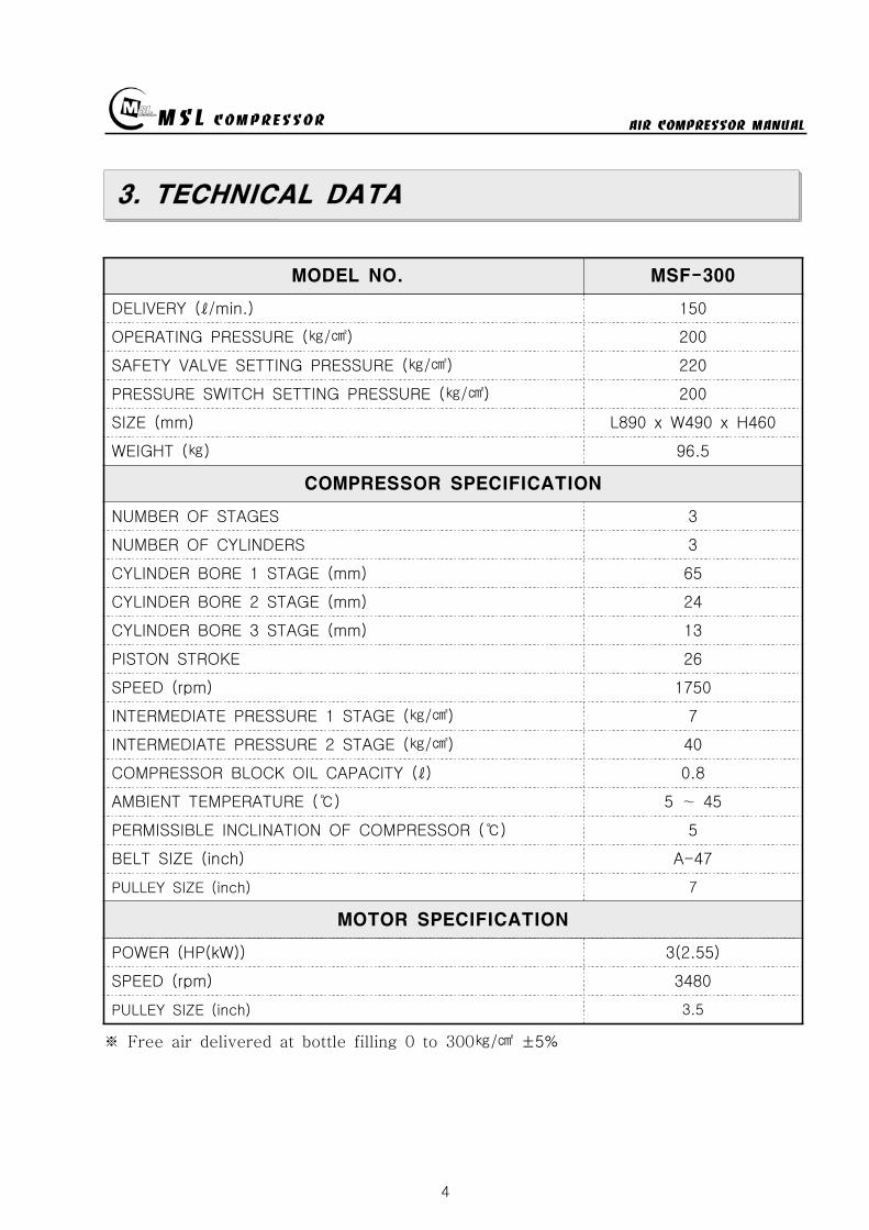
MSL COMPRESSOR AIR COMPRESSOR MANUAL
4
3 TECHNICAL DATA
MODEL NO MSF-300
DELIVERY ( min)ℓ 150
OPERATING PRESSURE ( ) 200
SAFETY VALVE SETTING PRESSURE ( ) 220
PRESSURE SWITCH SETTING PRESSURE ( ) 200
SIZE (mm) L890 x W490 x H460
WEIGHT ( ) 965
COMPRESSOR SPECIFICATION
NUMBER OF STAGES 3
NUMBER OF CYLINDERS 3
CYLINDER BORE 1 STAGE (mm) 65
CYLINDER BORE 2 STAGE (mm) 24
CYLINDER BORE 3 STAGE (mm) 13
PISTON STROKE 26
SPEED (rpm) 1750
INTERMEDIATE PRESSURE 1 STAGE ( ) 7
INTERMEDIATE PRESSURE 2 STAGE ( ) 40
COMPRESSOR BLOCK OIL CAPACITY ( )ℓ 08
AMBIENT TEMPERATURE ( ) 5 sim 45
PERMISSIBLE INCLINATION OF COMPRESSOR ( ) 5
BELT SIZE (inch) A-47
PULLEY SIZE (inch) 7
MOTOR SPECIFICATION
POWER (HP(kW)) 3(255)
SPEED (rpm) 3480
PULLEY SIZE (inch) 35
Free air delivered at bottle filling 0 to 300 plusmn5
MSL COMPRESSOR AIR COMPRESSOR MANUAL
5
4 Applied MODEL
1 SUCTION FILTER
2 CONTROL BOX
3 START SW
4 PRESSURE SW
5 OIL DRAIN
6 WHEEL
7 OIL GAUGE
8 ONOFF SW
9 AIR CLEANING FILTER
10 MOTOR
MSL COMPRESSOR AIR COMPRESSOR MANUAL
6
5 Installation
5-1 Installation area
be well-ventilated
keep out of the sun snow and rain
The place having a little effect on the weather
The flat ground
5-2 Requirements for Environmental condition
No erosion
No the inflammables
No explosive gas
Clean area
No an interference around the COMPRESSOR
5-3 Install Base
Be far at least 500mm from a wall for the COOLING amp MAINTENANCE of COMPRESSOR
Install the SUCTION FILTER in the outside
Install the engine ventilation opening and suction filter to be the maximum distance
6 Operating
6-1 The user position of the COMPRESSOR
Be located near the STOP SWITCH of COMPRESSOR
6-2 The check condition of a trial run
Check the electric current complied with the electrical specifications of motor
Check the hindrance around rotating area
Check the oil capacity
Check the filter location if it is keep out of the sun snow and rain or not
Check the tightness of bolt and the leakage of air
Check the tension of BELT
Be well acquainted with preventive maintenance check list
MSL COMPRESSOR AIR COMPRESSOR MANUAL
7
6-3 Operating Procedure
Connect plug to receptacle or connect power conductor to load side of power
disconnecting device of power supply and turn the power disconnecting device
witch ON
Connect power conductor L1 L2 and L3 to the terminal of NFBS line side and
check whether compressor turns in accordance with an arrow direction or not If its
not interchanges conduct L2 and L3 and try again(check the phase sequence)
Electric power is supplied with on of NFB(None Fused Breaker)
(If a compressor power is over 5HP then red light turns on)
Combine by turning the connector of inlet hose
FOR 150200Kg METHOD FOR 300Kg
CONNECT
DISCHARGE
VALVE AND AIR
TANK
OPEN THE
DISCHARGE VALVE
(CCW)
LOCK THE
VENTING
VALVE (CW)
CAUTION
DO NOT FASTEN
TIGHTLY
MSL COMPRESSOR AIR COMPRESSOR MANUAL
8
Turn on the DISCHARGE VALVE of compressed air
Turn off the VENTING VALVE by turning to CW direction
(Be careful of the damage of packing and air leakage)
If you select the pressure level according to users equipment and illuminated
push button switch automatically turns on at the selected level
If the illuminated push button is pressed at properly selected level then the
compressor can start
If air tank is filled up by selected pressure level the motor will be turn off
and condensing water will be drained automatically(Option)
Turn off the pressure selector switch
Turn off(close) the air tank DISCHARGE VALVE
Drain the residual compressed air by turning VENTING VALVE
(Caution Prior to disconnecting of compressed air supply connector(valve)
residual compressed air in the supplying line must be vented out)
To disconnect compressed air supply connector from air tank
Turn the compressed air supply connecting valve to CCW direction
When fill-up operation is completed turn the main power supply tooff position
and drain the condensing water by opening the hand-operated valve below filter
MSL COMPRESSOR AIR COMPRESSOR MANUAL
9
7 Maintenance
7-1 Check OIL
Check the Oil status before starting a
machine
pour the Oil when it is needed l after
checking oil status
OIL TYPE BREATHING AIR COMPRESSOR OIL
7-2 AIR SUCTION FILTER
Install the suction filter on the outside
Filter the dust of air
Use the ELEMENT after cleaning when it is
dirty
exchange ELEMENT when it is impossible to use
Using the soiled filter is not good for performance
power consumption and durability
7-3 DRAIN VALVE
Extract the water by opening the drain valve when job is finished
AUTO DRAIN VALVE is automatically opened when the COMPRESSOR is stoped
AUTO DRAIN VALVE isnt worked on condition of having a some trouble in the
SOLENOID VALVE
Be required spacial attention in winter
- Be careful of damaging the COMPRESSOR BODY and LINE by the frozen air line
- Use the hot stove to melt the frozen DRAIN VALVE
- Always operate the ELECTRIC HEATER(Option) in wintertime if there is needed
7-4 PRESSURE GAUGE
AIR PRESSURE GAUGE denotes the pressure of air serviced and OIL PRESSURE
GAUGE denotes that of LUBRICATION OIL
PRESSURE GAUGE is required of special attention for a shock not to smash
Immediately exchange on condition of being damaged
Exchange PRESSURE GAUGE to certified one
SUCTION FILTER
MSL COMPRESSOR AIR COMPRESSOR MANUAL
10
7-5 SAFETY VALVE
SAFETY VALVE protects the machine for the higher pressure than settled pressure
Must be careful of the safety valve
Must be careful of the enclosed SAFETY VALVE
Immediately exchange the damaged SAFETY VALVE
In case of changing for a safety valve you must contact with a manufacturer
Do not touch SAFETY VALVE without manufacturers authorization
Only skilled engineer can regulate safety valves setting pressure
(Caution Never exceed over 110 of rated pressure)
SAFETY VALVE TYPE-I
High pressure settingTurn the PRESSURE ADJUST SCREW to CW①after loosening the LOCK NUT②Turn the LOCK NUT to CWafter setting②the pressure watching the Pressure gauge
Low pressure setting
Turn the PRESSURE ADJUST SCREW toCCW①after loosening the LOCK NUT②Turn the LOCK NUT toCW after setting②the pressure watching the pressure gauge
SAFETY VALVE TYPE-Ⅱ
High pressure setting
Turn the PRESSURE ADJUST SCREW to① CWafter loosening the LOCK NUT②Turn the LOCK NUT toCW after adjusting②the pressure watching the pressure gauge
Low pressure settingTurn the PRESSURE ADJUST SCREW to CCW①after loosening the LOCK NUT②Turn the LOCK NUT toCW after adjusting②the pressure watching the pressure gauge
FIG5 TYPE-Ⅱ
FIG4 SAFETY VALVE
TYPE-I
MSL COMPRESSOR AIR COMPRESSOR MANUAL
11
7-6 Other safety Device
PRESSURE SWITCH
Can stop running of compressor in case of over pressured situation
CCW PRESSURE UP CW (CLOCKWISE)
CW PRESSURE DOWN CCW (COUNTER CLOCKWISE)
THERMAL RELAY
- In case of the motors being stopped by overload settle the problem and
press the reset bar then relay will run because relay is standardized by the reset
method of hand-operated
- Check the screw and Fasten it per 4 months
- Clean electromagnetic contact surface per 4 months to remove the reason of noise
- Adjust control circuits voltage to rated voltage of operating coil as exactly as
possible
7-7 MOTOR
Checking points
- Check if the motor shaft can smoothly rotate by the hand or not
- Check The Belt tension and specifications in case of exchanging it
- Check if the power supply(Voltage Frequency Phase)is conform to name plate
- Power connections are performed after verifying the conformity with that of
name plate
Check during Operation
- The operating current of continually used motor must be lower than marked
(name plate) current If the operating current is higher than marked current
check the motor
- In order to check the rotation direction and wiring operate motor under no
loading
- If the rotating direction is reversed interchange two lines among three lines
FIG6 PRESSURE SW
MSL COMPRESSOR AIR COMPRESSOR MANUAL
12
7-8 AIR CLEANING FILTER
Compressed air is purified by filter so you must change filter per every 50 hours
The filter is consist of three small size (1 2 3 step filtering) or big one size
(1 step filtering)
In case of the filter of small sizes change
A and B step filter with new one and
one step filter can be reused by cleaning
Change filter
- Turn the filter case to CCW with supplied
filter opener and resolve it
- Change new one after cleaning the inner space
- Carefully turn the filter case to CW not to
damage the o-ring
① ② ③ ④ ⑤
7-9 Checking items after operation
Must open the drain valve after compressing operation to drain compressed water
Compressor heated is needed for changing compressor oil
FIG7 AIR CLEANING
FILTER
MSL COMPRESSOR AIR COMPRESSOR MANUAL
13
7-10 Ambient conditions for preservation
Operate compressor at least 10 minutes per a week because Compressors not
running for a long time causes a failure of the machine
Keep the compressor being covered indoor where is dry and clean
Always clean the COMPRESSOR
Check the compressor periodically with maintenance table or decrease of life time
and bad performance will be caused
In case of keeping of COMPRESSOR in damp condition for a long time it needs
unloaded rotation to get compressor oil into the cylinder after removing of the filter
A compressor installed with UNLOAD EQUIPMENT needs oil lubrication after
removing of connection nipple
7-11 V-belt tension
Readjust new V-belt after the first 25 operating hours
The best tension for a belt drive is the lowest possible where the belt under
full load does not slip
A rough value for this is when the belt deflects 10 when pressed with thumb
pressure between the two pulleys
FIG8 BELT TENSION
10 mm
MSL COMPRESSOR AIR COMPRESSOR MANUAL
14
7-12 Torque sequence
Lighten valve head and cylinder boltsnuts equally in the sequence shown in
figuration
FIG9 TORQUE SEQUENCE
7-13 Tightening torque values
Unless otherwise specified in text the following torque values apply
All valve head screws require torque wrench tightening
The indicated torque values are valid for bolts in greased condition
Replace self-retaining nuts on reassembly
BOLT TYPE BOLT SIZE MAX TORQUE
HEXAGON BOLT M6 10 Nm
HEXAGON BOLT M8 25 Nm
HEXAGON BOLT M10 45 Nm
HEXAGON BOLT M12 75 Nm
HEXAGON BOLT M14 120 Nm
HEXAGON BOLT M16 200 Nm
7-14 CLEAN SEPARATOR
Remove and clean sintered filter element as follows or exchange it if completely
clogged
Remove piping connected to filter head Remove filter head along with sintered
filter element
Remove centre screw and separate sintered filter element baffle and vortex
plate from the filter head
To clean filter element use hot soapy water and blow dry with compressed air
MSL COMPRESSOR AIR COMPRESSOR MANUAL
15
8 Troubleshooting
Problem Reason Action
No rotation1Burn out of cylinderand piston
Service to manufacturer
COMPRESSOR overheat
1Failure of ventvalve2Obstructed suctionfilter
Change valve
Clean and change of filter
Fill up time is too long
1Failure of suction valve2Air line leakage3Failure of nipple4Obstructed suction filter5Failure of unload valve
Change valve Change the line with air leakage Check the nipple Clean and change of suction filter Applied lubrication oil after removement of unload nipple
Abnormal noise
1Worn down2Shortage of oil3Obstructed suction filter
Change parts Supply oil Check filter
No rotation of MOTOR
1A stoppage of electriccurrent2A break in a wire3Failure of motor starter4Bad contacting
Check the incoming wire connection Check wire disconnection Check the contact point Fasten the terminal screw Check switch
Overheated motor
1Overload2Fluctuation of Supplingvoltage and Frequency3Over voltage and voltagedips4Dad cooling
Check the rated current Check the voltage and frequency
Clean the cooling area
Reverse rotation ofmotor
1Main power supplyconnection error
Check the 3phase sequence
Can not startengine(In case of usingengine instead ofmotor)
1Discharged battery2Bad contact of electricequipment3Failure of start motor4Bad contact5Failure of generator
Fasten terminal screw fully Check switch function
Check power cable Change generator Refer to the engine manual
Electrical error
1Unexpected protectivefunction(Turn-off) of NFB
2Malfunctioning ofpressure switch
Check short-circuit Overload(Rating and setting of overcorrect protectivedevices)
Check power wire Check air line Check selected pressure Change PRESSURE SWITCH
Failure of autodrain valve
1Malfunctioning of solvalve
2Malfunctioning ofautomatic drain valve
Change SOLENOID VALVE Obstructed air line by ingress of solid bodies and liquids(Clean the line)
Check the line in the wintertime against rupture by freezing Check the wiring Ingress of solid bodies and liquids(Clean up everything) In the wintertime obstructed air line by freezing(Melt by Hot air gun)
Check air line
Failure of safetyvalve
1Ingress of external solidbodies and liquids
Clean up the ingress of solid bodies and liquids Change safety valve
AIR condensationtime is too long
1 Check the air line leakage(Verify the air line leakage under main power off afterrise up air line pressure at 150
2 Check the air leak about drain during operating conditionIf there air leakage detected change SOLENOID VALVE
3 Check the third and fourth step head and pipe NIPPLE
MSL COMPRESSOR AIR COMPRESSOR MANUAL
16
9 Preventive Maintenance
ACTIONPERIOD
TIMEHOUR DAY WEEK MONTH
QUAR-TER
HALF-YEAR YEAR
2YEAR
Clean and assembling condition
(each part of compressor)
Check CRANK CASE OIL
Check DRAIN VALVE
Check AIR leakage
Check PRESSURE GAUGE
Check PRESSURE Switch
Clean SUCTION FILTER
Check SAFETY VALVE
Check BELT tension
Change SUCTION FILTER
Check SUCTION amp DISCHARGE VALVE
CheckChange OIL FILTER ELEMENT
Change CRANK CASE OIL 50
Change DISCHARGE FILTER ELEMENT 50
Check SEPARATOR
Clean SEPARATOR
Check piston ring
MSL COMPRESSOR AIR COMPRESSOR MANUAL
P A R T L IS TMODEL MSF-300
MSL COMPRESSOR Co LtdHEAD OFFICE TEL 82 31 541 7000 FAX 82 31 542 2999HOME httpwwwmslcompcom
MSL COMPRESSOR AIR COMPRESSOR MANUAL
18
MSL COMPRESSOR AIR COMPRESSOR MANUAL
B HEAD ASSY
MSL COMPRESSOR AIR COMPRESSOR MANUAL
B HEAD ASSYKEY No PART No DESCRIPTION (Qty) NOTE
01 B-300-A-001 CRANK CASE
02 B-300-A-002 OIL GAUGE
03 B-300-F-001 SNAP RING
04 B-300-A-003 CRANK SHAFT
05 B-300-A-004 KEY
06 6306 BEARING
07 B-300-G-001 GASKET
08 B-300-A-005 BEARING COVER
09 B-300-A-006 OIL SEAL
10 6305ZZ BEARING
11 B-300-A-007 PULLEY
12 B-300-B-001 WASHER
13 B-300-B-002 BOLT
14 B-300-A-008 1 STAGE CONNECTION ROD
15 B-300-A-009 1 STAGE PISTON
16 B-300-A-010 1 STAGE PISTON PIN
17 B-300-F-002 SNAP RING
18 B-300-H-001 1 STAGE PISTON RING SET
19 B-300-G-002 GASKET
20 B-300-A-011 1 STAGE CYLINDER
21 B-300-B-003 SPRING WASHER
22 B-300-B-004 BOLT
23 B-300-G-003 GASKET
24 B-300-A-012 1 STAGE SUCTION amp DISCHARGE VALVE
25 B-300-B-005 BOLT
26 B-300-G-004 1 STAGE CYLINDER HEAD
26-1 B-300-G-004-1 BOLT
27 B-300-A-041 BOLT
28 B-300-A-042 GASKET
29 B-300-A-043 CAP NUT
MSL COMPRESSOR AIR COMPRESSOR MANUAL
B-B HEAD ASSYKEY No PART No DESCRIPTION (Qty) NOTE
30 B-300-A-014 2 STAGE CONNECTION ROD
30-1 B-300-A-014-1 3 STAGE CONNECTION ROD
31 B-300-A-015 23 STAGE PISTON PIN
32 B-300-A-016 2 STAGE PISTON
32-1 B-300-A-016-1 2 STAGE PISTON RING
33 B-300-G-005 GASKET
34 B-300-A-017 2 STAGE CYLINDER
35 B-300-G-005 GASKET
36 B-300-H-004 2 STAGE SD VALVE
37 B-300-A-018 2 STAGE CYLINDER HEAD
38 B-300-B-006 BOLT
39 B-300-A-019 3 STAGE PISTON
40 B-300-G-006 GASKET
41 B-300-A-020 3 STAGE CYLINDER
42 B-300-H-005 3 STAGE SD VALVE
43 B-300-A-021 3 STAGE CYLINDER HEAD
44 B-300-B-007 SPRING WASHER
45 B-300-B-008 BOLT
46 B-300-A-035 3 STAGE SPARE PISTON
47 B-300-A-036 2 STAGE SLEEVE
48 B-300-A-037 3 STAGE SLEEVE
49 HK3516 BEARING
50 HK1616B BEARING
51 B-300-A-038 2 STAGE VALVE BODY
52 B-300-A-039 3 STAGE VALVE BODY
53 B-300-A-040 SLEEVE HEAD GUARD
MSL COMPRESSOR AIR COMPRESSOR MANUAL
C 1 2 STAGE FILTER SETS
MSL COMPRESSOR AIR COMPRESSOR MANUAL
C 12 STAGE FILTER SETSKEY No PART No DESCRIPTION (Qty) NOTE
01 B-300-A-028 BODY
02 B-300-A-029 1 STAGE FILTER DOWN CAP
03 B-300-F-005 O-RING
04 B-300-A-030 1 STAGE FILTER ELEMENT
05 B-300-H-015 1 STAGE FILTER ELEMENT SET
06 B-300-H-016 1 STAGE FILTER DOWN CAP SET
07 B-300-F-006 O-RING
08 B-300-B-017 ALLEN SCREW
09 B-300-B-018 WASHER
10 B-300-B-019 SPRING WASHER
11 B-300-A-031 DRAIN VALVE
12 B-300-A-032 2 STAGE FILTER DOWN CAP
13 B-300-H-017 2 STAGE FILTER DOWN CAP SET
14 B-300-A-033 2 STAGE FILTER ELEMENT
15 B-300-H-018 2 STAGE FILTER ELEMENT SET
16 B-300-B-020 ALLEN SCREW
MSL COMPRESSOR AIR COMPRESSOR MANUAL
D AIR COOLING SYSTEM
MSL COMPRESSOR AIR COMPRESSOR MANUAL
D AIR COOLING SYSTEMKEY No PART No DESCRIPTION (Qty) NOTE
01 B-300-H-001 1 STAGE INTER COOLER SET 4
02 B-300-H-002 2 STAGE INTER COOLER SET 2
03 B-300-H-003 AFTER COOLER SET 2
04 B-300-H-004 AIR CONNECTING PIPE SET 4
05 B-300-H-005 CONNECTOR 7
06 B-300-H-006 CONNECTOR 2
07 B-300-H-007 CONNECTOR 2
08 B-300-B-008 SAFETY VALVE 1
09 B-300-B-009 CONNECTOR 1
MSL COMPRESSOR AIR COMPRESSOR MANUAL
E SEPARATOR SET
MSL COMPRESSOR AIR COMPRESSOR MANUAL
E SEPARATOR SETKEY No PART No DESCRIPTION (Qty) NOTE
01 B-300-A-023 BODY
02 B-300-A-024 SEPARATOR DOWN CAP
03 B-300-F-003 O-RING
04 B-300-H-013 SEPARATOR DOWN CAP SET
05 B-300-A-024 DRAIN VALVE
06 B-300-B-013 ALLEN SCREW
07 B-300-B-014 WASHER
08 B-300-B-015 SPRING WASHER
09 B-300-A-025 BOTTOM COVER
10 B-300-A-026 BEADS
11 B-300-A-027 TOP COVER
12 B-300-F-004 SPRING
13 B-300-H-014 ELEMENT SET
14 B-300-B-016 ALLEN SCREW
MSL COMPRESSOR AIR COMPRESSOR MANUAL
MSL COMPRESSOR AIR COMPRESSOR MANUAL
MSL COMPRESSOR AIR COMPRESSOR MANUAL
MSL COMPRESSOR AIR COMPRESSOR MANUAL
MEMO
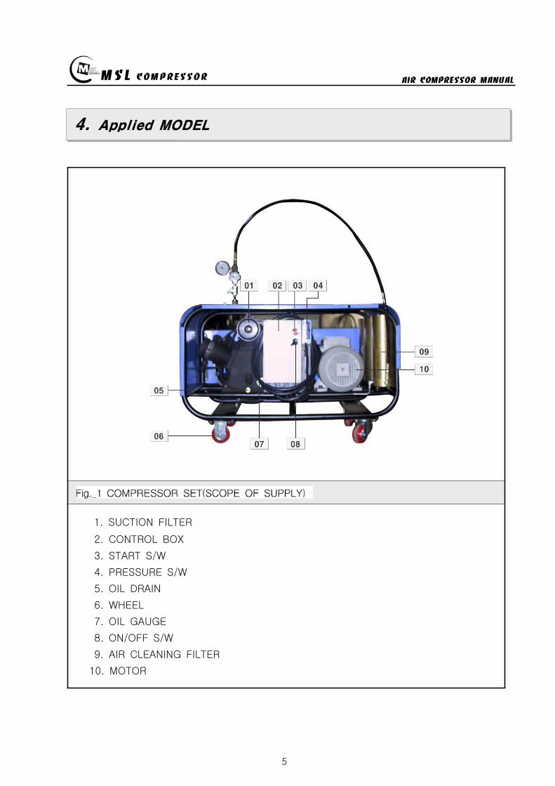
MSL COMPRESSOR AIR COMPRESSOR MANUAL
5
4 Applied MODEL
1 SUCTION FILTER
2 CONTROL BOX
3 START SW
4 PRESSURE SW
5 OIL DRAIN
6 WHEEL
7 OIL GAUGE
8 ONOFF SW
9 AIR CLEANING FILTER
10 MOTOR
MSL COMPRESSOR AIR COMPRESSOR MANUAL
6
5 Installation
5-1 Installation area
be well-ventilated
keep out of the sun snow and rain
The place having a little effect on the weather
The flat ground
5-2 Requirements for Environmental condition
No erosion
No the inflammables
No explosive gas
Clean area
No an interference around the COMPRESSOR
5-3 Install Base
Be far at least 500mm from a wall for the COOLING amp MAINTENANCE of COMPRESSOR
Install the SUCTION FILTER in the outside
Install the engine ventilation opening and suction filter to be the maximum distance
6 Operating
6-1 The user position of the COMPRESSOR
Be located near the STOP SWITCH of COMPRESSOR
6-2 The check condition of a trial run
Check the electric current complied with the electrical specifications of motor
Check the hindrance around rotating area
Check the oil capacity
Check the filter location if it is keep out of the sun snow and rain or not
Check the tightness of bolt and the leakage of air
Check the tension of BELT
Be well acquainted with preventive maintenance check list
MSL COMPRESSOR AIR COMPRESSOR MANUAL
7
6-3 Operating Procedure
Connect plug to receptacle or connect power conductor to load side of power
disconnecting device of power supply and turn the power disconnecting device
witch ON
Connect power conductor L1 L2 and L3 to the terminal of NFBS line side and
check whether compressor turns in accordance with an arrow direction or not If its
not interchanges conduct L2 and L3 and try again(check the phase sequence)
Electric power is supplied with on of NFB(None Fused Breaker)
(If a compressor power is over 5HP then red light turns on)
Combine by turning the connector of inlet hose
FOR 150200Kg METHOD FOR 300Kg
CONNECT
DISCHARGE
VALVE AND AIR
TANK
OPEN THE
DISCHARGE VALVE
(CCW)
LOCK THE
VENTING
VALVE (CW)
CAUTION
DO NOT FASTEN
TIGHTLY
MSL COMPRESSOR AIR COMPRESSOR MANUAL
8
Turn on the DISCHARGE VALVE of compressed air
Turn off the VENTING VALVE by turning to CW direction
(Be careful of the damage of packing and air leakage)
If you select the pressure level according to users equipment and illuminated
push button switch automatically turns on at the selected level
If the illuminated push button is pressed at properly selected level then the
compressor can start
If air tank is filled up by selected pressure level the motor will be turn off
and condensing water will be drained automatically(Option)
Turn off the pressure selector switch
Turn off(close) the air tank DISCHARGE VALVE
Drain the residual compressed air by turning VENTING VALVE
(Caution Prior to disconnecting of compressed air supply connector(valve)
residual compressed air in the supplying line must be vented out)
To disconnect compressed air supply connector from air tank
Turn the compressed air supply connecting valve to CCW direction
When fill-up operation is completed turn the main power supply tooff position
and drain the condensing water by opening the hand-operated valve below filter
MSL COMPRESSOR AIR COMPRESSOR MANUAL
9
7 Maintenance
7-1 Check OIL
Check the Oil status before starting a
machine
pour the Oil when it is needed l after
checking oil status
OIL TYPE BREATHING AIR COMPRESSOR OIL
7-2 AIR SUCTION FILTER
Install the suction filter on the outside
Filter the dust of air
Use the ELEMENT after cleaning when it is
dirty
exchange ELEMENT when it is impossible to use
Using the soiled filter is not good for performance
power consumption and durability
7-3 DRAIN VALVE
Extract the water by opening the drain valve when job is finished
AUTO DRAIN VALVE is automatically opened when the COMPRESSOR is stoped
AUTO DRAIN VALVE isnt worked on condition of having a some trouble in the
SOLENOID VALVE
Be required spacial attention in winter
- Be careful of damaging the COMPRESSOR BODY and LINE by the frozen air line
- Use the hot stove to melt the frozen DRAIN VALVE
- Always operate the ELECTRIC HEATER(Option) in wintertime if there is needed
7-4 PRESSURE GAUGE
AIR PRESSURE GAUGE denotes the pressure of air serviced and OIL PRESSURE
GAUGE denotes that of LUBRICATION OIL
PRESSURE GAUGE is required of special attention for a shock not to smash
Immediately exchange on condition of being damaged
Exchange PRESSURE GAUGE to certified one
SUCTION FILTER
MSL COMPRESSOR AIR COMPRESSOR MANUAL
10
7-5 SAFETY VALVE
SAFETY VALVE protects the machine for the higher pressure than settled pressure
Must be careful of the safety valve
Must be careful of the enclosed SAFETY VALVE
Immediately exchange the damaged SAFETY VALVE
In case of changing for a safety valve you must contact with a manufacturer
Do not touch SAFETY VALVE without manufacturers authorization
Only skilled engineer can regulate safety valves setting pressure
(Caution Never exceed over 110 of rated pressure)
SAFETY VALVE TYPE-I
High pressure settingTurn the PRESSURE ADJUST SCREW to CW①after loosening the LOCK NUT②Turn the LOCK NUT to CWafter setting②the pressure watching the Pressure gauge
Low pressure setting
Turn the PRESSURE ADJUST SCREW toCCW①after loosening the LOCK NUT②Turn the LOCK NUT toCW after setting②the pressure watching the pressure gauge
SAFETY VALVE TYPE-Ⅱ
High pressure setting
Turn the PRESSURE ADJUST SCREW to① CWafter loosening the LOCK NUT②Turn the LOCK NUT toCW after adjusting②the pressure watching the pressure gauge
Low pressure settingTurn the PRESSURE ADJUST SCREW to CCW①after loosening the LOCK NUT②Turn the LOCK NUT toCW after adjusting②the pressure watching the pressure gauge
FIG5 TYPE-Ⅱ
FIG4 SAFETY VALVE
TYPE-I
MSL COMPRESSOR AIR COMPRESSOR MANUAL
11
7-6 Other safety Device
PRESSURE SWITCH
Can stop running of compressor in case of over pressured situation
CCW PRESSURE UP CW (CLOCKWISE)
CW PRESSURE DOWN CCW (COUNTER CLOCKWISE)
THERMAL RELAY
- In case of the motors being stopped by overload settle the problem and
press the reset bar then relay will run because relay is standardized by the reset
method of hand-operated
- Check the screw and Fasten it per 4 months
- Clean electromagnetic contact surface per 4 months to remove the reason of noise
- Adjust control circuits voltage to rated voltage of operating coil as exactly as
possible
7-7 MOTOR
Checking points
- Check if the motor shaft can smoothly rotate by the hand or not
- Check The Belt tension and specifications in case of exchanging it
- Check if the power supply(Voltage Frequency Phase)is conform to name plate
- Power connections are performed after verifying the conformity with that of
name plate
Check during Operation
- The operating current of continually used motor must be lower than marked
(name plate) current If the operating current is higher than marked current
check the motor
- In order to check the rotation direction and wiring operate motor under no
loading
- If the rotating direction is reversed interchange two lines among three lines
FIG6 PRESSURE SW
MSL COMPRESSOR AIR COMPRESSOR MANUAL
12
7-8 AIR CLEANING FILTER
Compressed air is purified by filter so you must change filter per every 50 hours
The filter is consist of three small size (1 2 3 step filtering) or big one size
(1 step filtering)
In case of the filter of small sizes change
A and B step filter with new one and
one step filter can be reused by cleaning
Change filter
- Turn the filter case to CCW with supplied
filter opener and resolve it
- Change new one after cleaning the inner space
- Carefully turn the filter case to CW not to
damage the o-ring
① ② ③ ④ ⑤
7-9 Checking items after operation
Must open the drain valve after compressing operation to drain compressed water
Compressor heated is needed for changing compressor oil
FIG7 AIR CLEANING
FILTER
MSL COMPRESSOR AIR COMPRESSOR MANUAL
13
7-10 Ambient conditions for preservation
Operate compressor at least 10 minutes per a week because Compressors not
running for a long time causes a failure of the machine
Keep the compressor being covered indoor where is dry and clean
Always clean the COMPRESSOR
Check the compressor periodically with maintenance table or decrease of life time
and bad performance will be caused
In case of keeping of COMPRESSOR in damp condition for a long time it needs
unloaded rotation to get compressor oil into the cylinder after removing of the filter
A compressor installed with UNLOAD EQUIPMENT needs oil lubrication after
removing of connection nipple
7-11 V-belt tension
Readjust new V-belt after the first 25 operating hours
The best tension for a belt drive is the lowest possible where the belt under
full load does not slip
A rough value for this is when the belt deflects 10 when pressed with thumb
pressure between the two pulleys
FIG8 BELT TENSION
10 mm
MSL COMPRESSOR AIR COMPRESSOR MANUAL
14
7-12 Torque sequence
Lighten valve head and cylinder boltsnuts equally in the sequence shown in
figuration
FIG9 TORQUE SEQUENCE
7-13 Tightening torque values
Unless otherwise specified in text the following torque values apply
All valve head screws require torque wrench tightening
The indicated torque values are valid for bolts in greased condition
Replace self-retaining nuts on reassembly
BOLT TYPE BOLT SIZE MAX TORQUE
HEXAGON BOLT M6 10 Nm
HEXAGON BOLT M8 25 Nm
HEXAGON BOLT M10 45 Nm
HEXAGON BOLT M12 75 Nm
HEXAGON BOLT M14 120 Nm
HEXAGON BOLT M16 200 Nm
7-14 CLEAN SEPARATOR
Remove and clean sintered filter element as follows or exchange it if completely
clogged
Remove piping connected to filter head Remove filter head along with sintered
filter element
Remove centre screw and separate sintered filter element baffle and vortex
plate from the filter head
To clean filter element use hot soapy water and blow dry with compressed air
MSL COMPRESSOR AIR COMPRESSOR MANUAL
15
8 Troubleshooting
Problem Reason Action
No rotation1Burn out of cylinderand piston
Service to manufacturer
COMPRESSOR overheat
1Failure of ventvalve2Obstructed suctionfilter
Change valve
Clean and change of filter
Fill up time is too long
1Failure of suction valve2Air line leakage3Failure of nipple4Obstructed suction filter5Failure of unload valve
Change valve Change the line with air leakage Check the nipple Clean and change of suction filter Applied lubrication oil after removement of unload nipple
Abnormal noise
1Worn down2Shortage of oil3Obstructed suction filter
Change parts Supply oil Check filter
No rotation of MOTOR
1A stoppage of electriccurrent2A break in a wire3Failure of motor starter4Bad contacting
Check the incoming wire connection Check wire disconnection Check the contact point Fasten the terminal screw Check switch
Overheated motor
1Overload2Fluctuation of Supplingvoltage and Frequency3Over voltage and voltagedips4Dad cooling
Check the rated current Check the voltage and frequency
Clean the cooling area
Reverse rotation ofmotor
1Main power supplyconnection error
Check the 3phase sequence
Can not startengine(In case of usingengine instead ofmotor)
1Discharged battery2Bad contact of electricequipment3Failure of start motor4Bad contact5Failure of generator
Fasten terminal screw fully Check switch function
Check power cable Change generator Refer to the engine manual
Electrical error
1Unexpected protectivefunction(Turn-off) of NFB
2Malfunctioning ofpressure switch
Check short-circuit Overload(Rating and setting of overcorrect protectivedevices)
Check power wire Check air line Check selected pressure Change PRESSURE SWITCH
Failure of autodrain valve
1Malfunctioning of solvalve
2Malfunctioning ofautomatic drain valve
Change SOLENOID VALVE Obstructed air line by ingress of solid bodies and liquids(Clean the line)
Check the line in the wintertime against rupture by freezing Check the wiring Ingress of solid bodies and liquids(Clean up everything) In the wintertime obstructed air line by freezing(Melt by Hot air gun)
Check air line
Failure of safetyvalve
1Ingress of external solidbodies and liquids
Clean up the ingress of solid bodies and liquids Change safety valve
AIR condensationtime is too long
1 Check the air line leakage(Verify the air line leakage under main power off afterrise up air line pressure at 150
2 Check the air leak about drain during operating conditionIf there air leakage detected change SOLENOID VALVE
3 Check the third and fourth step head and pipe NIPPLE
MSL COMPRESSOR AIR COMPRESSOR MANUAL
16
9 Preventive Maintenance
ACTIONPERIOD
TIMEHOUR DAY WEEK MONTH
QUAR-TER
HALF-YEAR YEAR
2YEAR
Clean and assembling condition
(each part of compressor)
Check CRANK CASE OIL
Check DRAIN VALVE
Check AIR leakage
Check PRESSURE GAUGE
Check PRESSURE Switch
Clean SUCTION FILTER
Check SAFETY VALVE
Check BELT tension
Change SUCTION FILTER
Check SUCTION amp DISCHARGE VALVE
CheckChange OIL FILTER ELEMENT
Change CRANK CASE OIL 50
Change DISCHARGE FILTER ELEMENT 50
Check SEPARATOR
Clean SEPARATOR
Check piston ring
MSL COMPRESSOR AIR COMPRESSOR MANUAL
P A R T L IS TMODEL MSF-300
MSL COMPRESSOR Co LtdHEAD OFFICE TEL 82 31 541 7000 FAX 82 31 542 2999HOME httpwwwmslcompcom
MSL COMPRESSOR AIR COMPRESSOR MANUAL
18
MSL COMPRESSOR AIR COMPRESSOR MANUAL
B HEAD ASSY
MSL COMPRESSOR AIR COMPRESSOR MANUAL
B HEAD ASSYKEY No PART No DESCRIPTION (Qty) NOTE
01 B-300-A-001 CRANK CASE
02 B-300-A-002 OIL GAUGE
03 B-300-F-001 SNAP RING
04 B-300-A-003 CRANK SHAFT
05 B-300-A-004 KEY
06 6306 BEARING
07 B-300-G-001 GASKET
08 B-300-A-005 BEARING COVER
09 B-300-A-006 OIL SEAL
10 6305ZZ BEARING
11 B-300-A-007 PULLEY
12 B-300-B-001 WASHER
13 B-300-B-002 BOLT
14 B-300-A-008 1 STAGE CONNECTION ROD
15 B-300-A-009 1 STAGE PISTON
16 B-300-A-010 1 STAGE PISTON PIN
17 B-300-F-002 SNAP RING
18 B-300-H-001 1 STAGE PISTON RING SET
19 B-300-G-002 GASKET
20 B-300-A-011 1 STAGE CYLINDER
21 B-300-B-003 SPRING WASHER
22 B-300-B-004 BOLT
23 B-300-G-003 GASKET
24 B-300-A-012 1 STAGE SUCTION amp DISCHARGE VALVE
25 B-300-B-005 BOLT
26 B-300-G-004 1 STAGE CYLINDER HEAD
26-1 B-300-G-004-1 BOLT
27 B-300-A-041 BOLT
28 B-300-A-042 GASKET
29 B-300-A-043 CAP NUT
MSL COMPRESSOR AIR COMPRESSOR MANUAL
B-B HEAD ASSYKEY No PART No DESCRIPTION (Qty) NOTE
30 B-300-A-014 2 STAGE CONNECTION ROD
30-1 B-300-A-014-1 3 STAGE CONNECTION ROD
31 B-300-A-015 23 STAGE PISTON PIN
32 B-300-A-016 2 STAGE PISTON
32-1 B-300-A-016-1 2 STAGE PISTON RING
33 B-300-G-005 GASKET
34 B-300-A-017 2 STAGE CYLINDER
35 B-300-G-005 GASKET
36 B-300-H-004 2 STAGE SD VALVE
37 B-300-A-018 2 STAGE CYLINDER HEAD
38 B-300-B-006 BOLT
39 B-300-A-019 3 STAGE PISTON
40 B-300-G-006 GASKET
41 B-300-A-020 3 STAGE CYLINDER
42 B-300-H-005 3 STAGE SD VALVE
43 B-300-A-021 3 STAGE CYLINDER HEAD
44 B-300-B-007 SPRING WASHER
45 B-300-B-008 BOLT
46 B-300-A-035 3 STAGE SPARE PISTON
47 B-300-A-036 2 STAGE SLEEVE
48 B-300-A-037 3 STAGE SLEEVE
49 HK3516 BEARING
50 HK1616B BEARING
51 B-300-A-038 2 STAGE VALVE BODY
52 B-300-A-039 3 STAGE VALVE BODY
53 B-300-A-040 SLEEVE HEAD GUARD
MSL COMPRESSOR AIR COMPRESSOR MANUAL
C 1 2 STAGE FILTER SETS
MSL COMPRESSOR AIR COMPRESSOR MANUAL
C 12 STAGE FILTER SETSKEY No PART No DESCRIPTION (Qty) NOTE
01 B-300-A-028 BODY
02 B-300-A-029 1 STAGE FILTER DOWN CAP
03 B-300-F-005 O-RING
04 B-300-A-030 1 STAGE FILTER ELEMENT
05 B-300-H-015 1 STAGE FILTER ELEMENT SET
06 B-300-H-016 1 STAGE FILTER DOWN CAP SET
07 B-300-F-006 O-RING
08 B-300-B-017 ALLEN SCREW
09 B-300-B-018 WASHER
10 B-300-B-019 SPRING WASHER
11 B-300-A-031 DRAIN VALVE
12 B-300-A-032 2 STAGE FILTER DOWN CAP
13 B-300-H-017 2 STAGE FILTER DOWN CAP SET
14 B-300-A-033 2 STAGE FILTER ELEMENT
15 B-300-H-018 2 STAGE FILTER ELEMENT SET
16 B-300-B-020 ALLEN SCREW
MSL COMPRESSOR AIR COMPRESSOR MANUAL
D AIR COOLING SYSTEM
MSL COMPRESSOR AIR COMPRESSOR MANUAL
D AIR COOLING SYSTEMKEY No PART No DESCRIPTION (Qty) NOTE
01 B-300-H-001 1 STAGE INTER COOLER SET 4
02 B-300-H-002 2 STAGE INTER COOLER SET 2
03 B-300-H-003 AFTER COOLER SET 2
04 B-300-H-004 AIR CONNECTING PIPE SET 4
05 B-300-H-005 CONNECTOR 7
06 B-300-H-006 CONNECTOR 2
07 B-300-H-007 CONNECTOR 2
08 B-300-B-008 SAFETY VALVE 1
09 B-300-B-009 CONNECTOR 1
MSL COMPRESSOR AIR COMPRESSOR MANUAL
E SEPARATOR SET
MSL COMPRESSOR AIR COMPRESSOR MANUAL
E SEPARATOR SETKEY No PART No DESCRIPTION (Qty) NOTE
01 B-300-A-023 BODY
02 B-300-A-024 SEPARATOR DOWN CAP
03 B-300-F-003 O-RING
04 B-300-H-013 SEPARATOR DOWN CAP SET
05 B-300-A-024 DRAIN VALVE
06 B-300-B-013 ALLEN SCREW
07 B-300-B-014 WASHER
08 B-300-B-015 SPRING WASHER
09 B-300-A-025 BOTTOM COVER
10 B-300-A-026 BEADS
11 B-300-A-027 TOP COVER
12 B-300-F-004 SPRING
13 B-300-H-014 ELEMENT SET
14 B-300-B-016 ALLEN SCREW
MSL COMPRESSOR AIR COMPRESSOR MANUAL
MSL COMPRESSOR AIR COMPRESSOR MANUAL
MSL COMPRESSOR AIR COMPRESSOR MANUAL
MSL COMPRESSOR AIR COMPRESSOR MANUAL
MEMO
MSL COMPRESSOR AIR COMPRESSOR MANUAL
6
5 Installation
5-1 Installation area
be well-ventilated
keep out of the sun snow and rain
The place having a little effect on the weather
The flat ground
5-2 Requirements for Environmental condition
No erosion
No the inflammables
No explosive gas
Clean area
No an interference around the COMPRESSOR
5-3 Install Base
Be far at least 500mm from a wall for the COOLING amp MAINTENANCE of COMPRESSOR
Install the SUCTION FILTER in the outside
Install the engine ventilation opening and suction filter to be the maximum distance
6 Operating
6-1 The user position of the COMPRESSOR
Be located near the STOP SWITCH of COMPRESSOR
6-2 The check condition of a trial run
Check the electric current complied with the electrical specifications of motor
Check the hindrance around rotating area
Check the oil capacity
Check the filter location if it is keep out of the sun snow and rain or not
Check the tightness of bolt and the leakage of air
Check the tension of BELT
Be well acquainted with preventive maintenance check list
MSL COMPRESSOR AIR COMPRESSOR MANUAL
7
6-3 Operating Procedure
Connect plug to receptacle or connect power conductor to load side of power
disconnecting device of power supply and turn the power disconnecting device
witch ON
Connect power conductor L1 L2 and L3 to the terminal of NFBS line side and
check whether compressor turns in accordance with an arrow direction or not If its
not interchanges conduct L2 and L3 and try again(check the phase sequence)
Electric power is supplied with on of NFB(None Fused Breaker)
(If a compressor power is over 5HP then red light turns on)
Combine by turning the connector of inlet hose
FOR 150200Kg METHOD FOR 300Kg
CONNECT
DISCHARGE
VALVE AND AIR
TANK
OPEN THE
DISCHARGE VALVE
(CCW)
LOCK THE
VENTING
VALVE (CW)
CAUTION
DO NOT FASTEN
TIGHTLY
MSL COMPRESSOR AIR COMPRESSOR MANUAL
8
Turn on the DISCHARGE VALVE of compressed air
Turn off the VENTING VALVE by turning to CW direction
(Be careful of the damage of packing and air leakage)
If you select the pressure level according to users equipment and illuminated
push button switch automatically turns on at the selected level
If the illuminated push button is pressed at properly selected level then the
compressor can start
If air tank is filled up by selected pressure level the motor will be turn off
and condensing water will be drained automatically(Option)
Turn off the pressure selector switch
Turn off(close) the air tank DISCHARGE VALVE
Drain the residual compressed air by turning VENTING VALVE
(Caution Prior to disconnecting of compressed air supply connector(valve)
residual compressed air in the supplying line must be vented out)
To disconnect compressed air supply connector from air tank
Turn the compressed air supply connecting valve to CCW direction
When fill-up operation is completed turn the main power supply tooff position
and drain the condensing water by opening the hand-operated valve below filter
MSL COMPRESSOR AIR COMPRESSOR MANUAL
9
7 Maintenance
7-1 Check OIL
Check the Oil status before starting a
machine
pour the Oil when it is needed l after
checking oil status
OIL TYPE BREATHING AIR COMPRESSOR OIL
7-2 AIR SUCTION FILTER
Install the suction filter on the outside
Filter the dust of air
Use the ELEMENT after cleaning when it is
dirty
exchange ELEMENT when it is impossible to use
Using the soiled filter is not good for performance
power consumption and durability
7-3 DRAIN VALVE
Extract the water by opening the drain valve when job is finished
AUTO DRAIN VALVE is automatically opened when the COMPRESSOR is stoped
AUTO DRAIN VALVE isnt worked on condition of having a some trouble in the
SOLENOID VALVE
Be required spacial attention in winter
- Be careful of damaging the COMPRESSOR BODY and LINE by the frozen air line
- Use the hot stove to melt the frozen DRAIN VALVE
- Always operate the ELECTRIC HEATER(Option) in wintertime if there is needed
7-4 PRESSURE GAUGE
AIR PRESSURE GAUGE denotes the pressure of air serviced and OIL PRESSURE
GAUGE denotes that of LUBRICATION OIL
PRESSURE GAUGE is required of special attention for a shock not to smash
Immediately exchange on condition of being damaged
Exchange PRESSURE GAUGE to certified one
SUCTION FILTER
MSL COMPRESSOR AIR COMPRESSOR MANUAL
10
7-5 SAFETY VALVE
SAFETY VALVE protects the machine for the higher pressure than settled pressure
Must be careful of the safety valve
Must be careful of the enclosed SAFETY VALVE
Immediately exchange the damaged SAFETY VALVE
In case of changing for a safety valve you must contact with a manufacturer
Do not touch SAFETY VALVE without manufacturers authorization
Only skilled engineer can regulate safety valves setting pressure
(Caution Never exceed over 110 of rated pressure)
SAFETY VALVE TYPE-I
High pressure settingTurn the PRESSURE ADJUST SCREW to CW①after loosening the LOCK NUT②Turn the LOCK NUT to CWafter setting②the pressure watching the Pressure gauge
Low pressure setting
Turn the PRESSURE ADJUST SCREW toCCW①after loosening the LOCK NUT②Turn the LOCK NUT toCW after setting②the pressure watching the pressure gauge
SAFETY VALVE TYPE-Ⅱ
High pressure setting
Turn the PRESSURE ADJUST SCREW to① CWafter loosening the LOCK NUT②Turn the LOCK NUT toCW after adjusting②the pressure watching the pressure gauge
Low pressure settingTurn the PRESSURE ADJUST SCREW to CCW①after loosening the LOCK NUT②Turn the LOCK NUT toCW after adjusting②the pressure watching the pressure gauge
FIG5 TYPE-Ⅱ
FIG4 SAFETY VALVE
TYPE-I
MSL COMPRESSOR AIR COMPRESSOR MANUAL
11
7-6 Other safety Device
PRESSURE SWITCH
Can stop running of compressor in case of over pressured situation
CCW PRESSURE UP CW (CLOCKWISE)
CW PRESSURE DOWN CCW (COUNTER CLOCKWISE)
THERMAL RELAY
- In case of the motors being stopped by overload settle the problem and
press the reset bar then relay will run because relay is standardized by the reset
method of hand-operated
- Check the screw and Fasten it per 4 months
- Clean electromagnetic contact surface per 4 months to remove the reason of noise
- Adjust control circuits voltage to rated voltage of operating coil as exactly as
possible
7-7 MOTOR
Checking points
- Check if the motor shaft can smoothly rotate by the hand or not
- Check The Belt tension and specifications in case of exchanging it
- Check if the power supply(Voltage Frequency Phase)is conform to name plate
- Power connections are performed after verifying the conformity with that of
name plate
Check during Operation
- The operating current of continually used motor must be lower than marked
(name plate) current If the operating current is higher than marked current
check the motor
- In order to check the rotation direction and wiring operate motor under no
loading
- If the rotating direction is reversed interchange two lines among three lines
FIG6 PRESSURE SW
MSL COMPRESSOR AIR COMPRESSOR MANUAL
12
7-8 AIR CLEANING FILTER
Compressed air is purified by filter so you must change filter per every 50 hours
The filter is consist of three small size (1 2 3 step filtering) or big one size
(1 step filtering)
In case of the filter of small sizes change
A and B step filter with new one and
one step filter can be reused by cleaning
Change filter
- Turn the filter case to CCW with supplied
filter opener and resolve it
- Change new one after cleaning the inner space
- Carefully turn the filter case to CW not to
damage the o-ring
① ② ③ ④ ⑤
7-9 Checking items after operation
Must open the drain valve after compressing operation to drain compressed water
Compressor heated is needed for changing compressor oil
FIG7 AIR CLEANING
FILTER
MSL COMPRESSOR AIR COMPRESSOR MANUAL
13
7-10 Ambient conditions for preservation
Operate compressor at least 10 minutes per a week because Compressors not
running for a long time causes a failure of the machine
Keep the compressor being covered indoor where is dry and clean
Always clean the COMPRESSOR
Check the compressor periodically with maintenance table or decrease of life time
and bad performance will be caused
In case of keeping of COMPRESSOR in damp condition for a long time it needs
unloaded rotation to get compressor oil into the cylinder after removing of the filter
A compressor installed with UNLOAD EQUIPMENT needs oil lubrication after
removing of connection nipple
7-11 V-belt tension
Readjust new V-belt after the first 25 operating hours
The best tension for a belt drive is the lowest possible where the belt under
full load does not slip
A rough value for this is when the belt deflects 10 when pressed with thumb
pressure between the two pulleys
FIG8 BELT TENSION
10 mm
MSL COMPRESSOR AIR COMPRESSOR MANUAL
14
7-12 Torque sequence
Lighten valve head and cylinder boltsnuts equally in the sequence shown in
figuration
FIG9 TORQUE SEQUENCE
7-13 Tightening torque values
Unless otherwise specified in text the following torque values apply
All valve head screws require torque wrench tightening
The indicated torque values are valid for bolts in greased condition
Replace self-retaining nuts on reassembly
BOLT TYPE BOLT SIZE MAX TORQUE
HEXAGON BOLT M6 10 Nm
HEXAGON BOLT M8 25 Nm
HEXAGON BOLT M10 45 Nm
HEXAGON BOLT M12 75 Nm
HEXAGON BOLT M14 120 Nm
HEXAGON BOLT M16 200 Nm
7-14 CLEAN SEPARATOR
Remove and clean sintered filter element as follows or exchange it if completely
clogged
Remove piping connected to filter head Remove filter head along with sintered
filter element
Remove centre screw and separate sintered filter element baffle and vortex
plate from the filter head
To clean filter element use hot soapy water and blow dry with compressed air
MSL COMPRESSOR AIR COMPRESSOR MANUAL
15
8 Troubleshooting
Problem Reason Action
No rotation1Burn out of cylinderand piston
Service to manufacturer
COMPRESSOR overheat
1Failure of ventvalve2Obstructed suctionfilter
Change valve
Clean and change of filter
Fill up time is too long
1Failure of suction valve2Air line leakage3Failure of nipple4Obstructed suction filter5Failure of unload valve
Change valve Change the line with air leakage Check the nipple Clean and change of suction filter Applied lubrication oil after removement of unload nipple
Abnormal noise
1Worn down2Shortage of oil3Obstructed suction filter
Change parts Supply oil Check filter
No rotation of MOTOR
1A stoppage of electriccurrent2A break in a wire3Failure of motor starter4Bad contacting
Check the incoming wire connection Check wire disconnection Check the contact point Fasten the terminal screw Check switch
Overheated motor
1Overload2Fluctuation of Supplingvoltage and Frequency3Over voltage and voltagedips4Dad cooling
Check the rated current Check the voltage and frequency
Clean the cooling area
Reverse rotation ofmotor
1Main power supplyconnection error
Check the 3phase sequence
Can not startengine(In case of usingengine instead ofmotor)
1Discharged battery2Bad contact of electricequipment3Failure of start motor4Bad contact5Failure of generator
Fasten terminal screw fully Check switch function
Check power cable Change generator Refer to the engine manual
Electrical error
1Unexpected protectivefunction(Turn-off) of NFB
2Malfunctioning ofpressure switch
Check short-circuit Overload(Rating and setting of overcorrect protectivedevices)
Check power wire Check air line Check selected pressure Change PRESSURE SWITCH
Failure of autodrain valve
1Malfunctioning of solvalve
2Malfunctioning ofautomatic drain valve
Change SOLENOID VALVE Obstructed air line by ingress of solid bodies and liquids(Clean the line)
Check the line in the wintertime against rupture by freezing Check the wiring Ingress of solid bodies and liquids(Clean up everything) In the wintertime obstructed air line by freezing(Melt by Hot air gun)
Check air line
Failure of safetyvalve
1Ingress of external solidbodies and liquids
Clean up the ingress of solid bodies and liquids Change safety valve
AIR condensationtime is too long
1 Check the air line leakage(Verify the air line leakage under main power off afterrise up air line pressure at 150
2 Check the air leak about drain during operating conditionIf there air leakage detected change SOLENOID VALVE
3 Check the third and fourth step head and pipe NIPPLE
MSL COMPRESSOR AIR COMPRESSOR MANUAL
16
9 Preventive Maintenance
ACTIONPERIOD
TIMEHOUR DAY WEEK MONTH
QUAR-TER
HALF-YEAR YEAR
2YEAR
Clean and assembling condition
(each part of compressor)
Check CRANK CASE OIL
Check DRAIN VALVE
Check AIR leakage
Check PRESSURE GAUGE
Check PRESSURE Switch
Clean SUCTION FILTER
Check SAFETY VALVE
Check BELT tension
Change SUCTION FILTER
Check SUCTION amp DISCHARGE VALVE
CheckChange OIL FILTER ELEMENT
Change CRANK CASE OIL 50
Change DISCHARGE FILTER ELEMENT 50
Check SEPARATOR
Clean SEPARATOR
Check piston ring
MSL COMPRESSOR AIR COMPRESSOR MANUAL
P A R T L IS TMODEL MSF-300
MSL COMPRESSOR Co LtdHEAD OFFICE TEL 82 31 541 7000 FAX 82 31 542 2999HOME httpwwwmslcompcom
MSL COMPRESSOR AIR COMPRESSOR MANUAL
18
MSL COMPRESSOR AIR COMPRESSOR MANUAL
B HEAD ASSY
MSL COMPRESSOR AIR COMPRESSOR MANUAL
B HEAD ASSYKEY No PART No DESCRIPTION (Qty) NOTE
01 B-300-A-001 CRANK CASE
02 B-300-A-002 OIL GAUGE
03 B-300-F-001 SNAP RING
04 B-300-A-003 CRANK SHAFT
05 B-300-A-004 KEY
06 6306 BEARING
07 B-300-G-001 GASKET
08 B-300-A-005 BEARING COVER
09 B-300-A-006 OIL SEAL
10 6305ZZ BEARING
11 B-300-A-007 PULLEY
12 B-300-B-001 WASHER
13 B-300-B-002 BOLT
14 B-300-A-008 1 STAGE CONNECTION ROD
15 B-300-A-009 1 STAGE PISTON
16 B-300-A-010 1 STAGE PISTON PIN
17 B-300-F-002 SNAP RING
18 B-300-H-001 1 STAGE PISTON RING SET
19 B-300-G-002 GASKET
20 B-300-A-011 1 STAGE CYLINDER
21 B-300-B-003 SPRING WASHER
22 B-300-B-004 BOLT
23 B-300-G-003 GASKET
24 B-300-A-012 1 STAGE SUCTION amp DISCHARGE VALVE
25 B-300-B-005 BOLT
26 B-300-G-004 1 STAGE CYLINDER HEAD
26-1 B-300-G-004-1 BOLT
27 B-300-A-041 BOLT
28 B-300-A-042 GASKET
29 B-300-A-043 CAP NUT
MSL COMPRESSOR AIR COMPRESSOR MANUAL
B-B HEAD ASSYKEY No PART No DESCRIPTION (Qty) NOTE
30 B-300-A-014 2 STAGE CONNECTION ROD
30-1 B-300-A-014-1 3 STAGE CONNECTION ROD
31 B-300-A-015 23 STAGE PISTON PIN
32 B-300-A-016 2 STAGE PISTON
32-1 B-300-A-016-1 2 STAGE PISTON RING
33 B-300-G-005 GASKET
34 B-300-A-017 2 STAGE CYLINDER
35 B-300-G-005 GASKET
36 B-300-H-004 2 STAGE SD VALVE
37 B-300-A-018 2 STAGE CYLINDER HEAD
38 B-300-B-006 BOLT
39 B-300-A-019 3 STAGE PISTON
40 B-300-G-006 GASKET
41 B-300-A-020 3 STAGE CYLINDER
42 B-300-H-005 3 STAGE SD VALVE
43 B-300-A-021 3 STAGE CYLINDER HEAD
44 B-300-B-007 SPRING WASHER
45 B-300-B-008 BOLT
46 B-300-A-035 3 STAGE SPARE PISTON
47 B-300-A-036 2 STAGE SLEEVE
48 B-300-A-037 3 STAGE SLEEVE
49 HK3516 BEARING
50 HK1616B BEARING
51 B-300-A-038 2 STAGE VALVE BODY
52 B-300-A-039 3 STAGE VALVE BODY
53 B-300-A-040 SLEEVE HEAD GUARD
MSL COMPRESSOR AIR COMPRESSOR MANUAL
C 1 2 STAGE FILTER SETS
MSL COMPRESSOR AIR COMPRESSOR MANUAL
C 12 STAGE FILTER SETSKEY No PART No DESCRIPTION (Qty) NOTE
01 B-300-A-028 BODY
02 B-300-A-029 1 STAGE FILTER DOWN CAP
03 B-300-F-005 O-RING
04 B-300-A-030 1 STAGE FILTER ELEMENT
05 B-300-H-015 1 STAGE FILTER ELEMENT SET
06 B-300-H-016 1 STAGE FILTER DOWN CAP SET
07 B-300-F-006 O-RING
08 B-300-B-017 ALLEN SCREW
09 B-300-B-018 WASHER
10 B-300-B-019 SPRING WASHER
11 B-300-A-031 DRAIN VALVE
12 B-300-A-032 2 STAGE FILTER DOWN CAP
13 B-300-H-017 2 STAGE FILTER DOWN CAP SET
14 B-300-A-033 2 STAGE FILTER ELEMENT
15 B-300-H-018 2 STAGE FILTER ELEMENT SET
16 B-300-B-020 ALLEN SCREW
MSL COMPRESSOR AIR COMPRESSOR MANUAL
D AIR COOLING SYSTEM
MSL COMPRESSOR AIR COMPRESSOR MANUAL
D AIR COOLING SYSTEMKEY No PART No DESCRIPTION (Qty) NOTE
01 B-300-H-001 1 STAGE INTER COOLER SET 4
02 B-300-H-002 2 STAGE INTER COOLER SET 2
03 B-300-H-003 AFTER COOLER SET 2
04 B-300-H-004 AIR CONNECTING PIPE SET 4
05 B-300-H-005 CONNECTOR 7
06 B-300-H-006 CONNECTOR 2
07 B-300-H-007 CONNECTOR 2
08 B-300-B-008 SAFETY VALVE 1
09 B-300-B-009 CONNECTOR 1
MSL COMPRESSOR AIR COMPRESSOR MANUAL
E SEPARATOR SET
MSL COMPRESSOR AIR COMPRESSOR MANUAL
E SEPARATOR SETKEY No PART No DESCRIPTION (Qty) NOTE
01 B-300-A-023 BODY
02 B-300-A-024 SEPARATOR DOWN CAP
03 B-300-F-003 O-RING
04 B-300-H-013 SEPARATOR DOWN CAP SET
05 B-300-A-024 DRAIN VALVE
06 B-300-B-013 ALLEN SCREW
07 B-300-B-014 WASHER
08 B-300-B-015 SPRING WASHER
09 B-300-A-025 BOTTOM COVER
10 B-300-A-026 BEADS
11 B-300-A-027 TOP COVER
12 B-300-F-004 SPRING
13 B-300-H-014 ELEMENT SET
14 B-300-B-016 ALLEN SCREW
MSL COMPRESSOR AIR COMPRESSOR MANUAL
MSL COMPRESSOR AIR COMPRESSOR MANUAL
MSL COMPRESSOR AIR COMPRESSOR MANUAL
MSL COMPRESSOR AIR COMPRESSOR MANUAL
MEMO
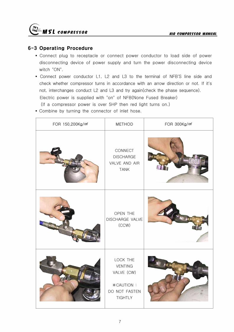
MSL COMPRESSOR AIR COMPRESSOR MANUAL
7
6-3 Operating Procedure
Connect plug to receptacle or connect power conductor to load side of power
disconnecting device of power supply and turn the power disconnecting device
witch ON
Connect power conductor L1 L2 and L3 to the terminal of NFBS line side and
check whether compressor turns in accordance with an arrow direction or not If its
not interchanges conduct L2 and L3 and try again(check the phase sequence)
Electric power is supplied with on of NFB(None Fused Breaker)
(If a compressor power is over 5HP then red light turns on)
Combine by turning the connector of inlet hose
FOR 150200Kg METHOD FOR 300Kg
CONNECT
DISCHARGE
VALVE AND AIR
TANK
OPEN THE
DISCHARGE VALVE
(CCW)
LOCK THE
VENTING
VALVE (CW)
CAUTION
DO NOT FASTEN
TIGHTLY
MSL COMPRESSOR AIR COMPRESSOR MANUAL
8
Turn on the DISCHARGE VALVE of compressed air
Turn off the VENTING VALVE by turning to CW direction
(Be careful of the damage of packing and air leakage)
If you select the pressure level according to users equipment and illuminated
push button switch automatically turns on at the selected level
If the illuminated push button is pressed at properly selected level then the
compressor can start
If air tank is filled up by selected pressure level the motor will be turn off
and condensing water will be drained automatically(Option)
Turn off the pressure selector switch
Turn off(close) the air tank DISCHARGE VALVE
Drain the residual compressed air by turning VENTING VALVE
(Caution Prior to disconnecting of compressed air supply connector(valve)
residual compressed air in the supplying line must be vented out)
To disconnect compressed air supply connector from air tank
Turn the compressed air supply connecting valve to CCW direction
When fill-up operation is completed turn the main power supply tooff position
and drain the condensing water by opening the hand-operated valve below filter
MSL COMPRESSOR AIR COMPRESSOR MANUAL
9
7 Maintenance
7-1 Check OIL
Check the Oil status before starting a
machine
pour the Oil when it is needed l after
checking oil status
OIL TYPE BREATHING AIR COMPRESSOR OIL
7-2 AIR SUCTION FILTER
Install the suction filter on the outside
Filter the dust of air
Use the ELEMENT after cleaning when it is
dirty
exchange ELEMENT when it is impossible to use
Using the soiled filter is not good for performance
power consumption and durability
7-3 DRAIN VALVE
Extract the water by opening the drain valve when job is finished
AUTO DRAIN VALVE is automatically opened when the COMPRESSOR is stoped
AUTO DRAIN VALVE isnt worked on condition of having a some trouble in the
SOLENOID VALVE
Be required spacial attention in winter
- Be careful of damaging the COMPRESSOR BODY and LINE by the frozen air line
- Use the hot stove to melt the frozen DRAIN VALVE
- Always operate the ELECTRIC HEATER(Option) in wintertime if there is needed
7-4 PRESSURE GAUGE
AIR PRESSURE GAUGE denotes the pressure of air serviced and OIL PRESSURE
GAUGE denotes that of LUBRICATION OIL
PRESSURE GAUGE is required of special attention for a shock not to smash
Immediately exchange on condition of being damaged
Exchange PRESSURE GAUGE to certified one
SUCTION FILTER
MSL COMPRESSOR AIR COMPRESSOR MANUAL
10
7-5 SAFETY VALVE
SAFETY VALVE protects the machine for the higher pressure than settled pressure
Must be careful of the safety valve
Must be careful of the enclosed SAFETY VALVE
Immediately exchange the damaged SAFETY VALVE
In case of changing for a safety valve you must contact with a manufacturer
Do not touch SAFETY VALVE without manufacturers authorization
Only skilled engineer can regulate safety valves setting pressure
(Caution Never exceed over 110 of rated pressure)
SAFETY VALVE TYPE-I
High pressure settingTurn the PRESSURE ADJUST SCREW to CW①after loosening the LOCK NUT②Turn the LOCK NUT to CWafter setting②the pressure watching the Pressure gauge
Low pressure setting
Turn the PRESSURE ADJUST SCREW toCCW①after loosening the LOCK NUT②Turn the LOCK NUT toCW after setting②the pressure watching the pressure gauge
SAFETY VALVE TYPE-Ⅱ
High pressure setting
Turn the PRESSURE ADJUST SCREW to① CWafter loosening the LOCK NUT②Turn the LOCK NUT toCW after adjusting②the pressure watching the pressure gauge
Low pressure settingTurn the PRESSURE ADJUST SCREW to CCW①after loosening the LOCK NUT②Turn the LOCK NUT toCW after adjusting②the pressure watching the pressure gauge
FIG5 TYPE-Ⅱ
FIG4 SAFETY VALVE
TYPE-I
MSL COMPRESSOR AIR COMPRESSOR MANUAL
11
7-6 Other safety Device
PRESSURE SWITCH
Can stop running of compressor in case of over pressured situation
CCW PRESSURE UP CW (CLOCKWISE)
CW PRESSURE DOWN CCW (COUNTER CLOCKWISE)
THERMAL RELAY
- In case of the motors being stopped by overload settle the problem and
press the reset bar then relay will run because relay is standardized by the reset
method of hand-operated
- Check the screw and Fasten it per 4 months
- Clean electromagnetic contact surface per 4 months to remove the reason of noise
- Adjust control circuits voltage to rated voltage of operating coil as exactly as
possible
7-7 MOTOR
Checking points
- Check if the motor shaft can smoothly rotate by the hand or not
- Check The Belt tension and specifications in case of exchanging it
- Check if the power supply(Voltage Frequency Phase)is conform to name plate
- Power connections are performed after verifying the conformity with that of
name plate
Check during Operation
- The operating current of continually used motor must be lower than marked
(name plate) current If the operating current is higher than marked current
check the motor
- In order to check the rotation direction and wiring operate motor under no
loading
- If the rotating direction is reversed interchange two lines among three lines
FIG6 PRESSURE SW
MSL COMPRESSOR AIR COMPRESSOR MANUAL
12
7-8 AIR CLEANING FILTER
Compressed air is purified by filter so you must change filter per every 50 hours
The filter is consist of three small size (1 2 3 step filtering) or big one size
(1 step filtering)
In case of the filter of small sizes change
A and B step filter with new one and
one step filter can be reused by cleaning
Change filter
- Turn the filter case to CCW with supplied
filter opener and resolve it
- Change new one after cleaning the inner space
- Carefully turn the filter case to CW not to
damage the o-ring
① ② ③ ④ ⑤
7-9 Checking items after operation
Must open the drain valve after compressing operation to drain compressed water
Compressor heated is needed for changing compressor oil
FIG7 AIR CLEANING
FILTER
MSL COMPRESSOR AIR COMPRESSOR MANUAL
13
7-10 Ambient conditions for preservation
Operate compressor at least 10 minutes per a week because Compressors not
running for a long time causes a failure of the machine
Keep the compressor being covered indoor where is dry and clean
Always clean the COMPRESSOR
Check the compressor periodically with maintenance table or decrease of life time
and bad performance will be caused
In case of keeping of COMPRESSOR in damp condition for a long time it needs
unloaded rotation to get compressor oil into the cylinder after removing of the filter
A compressor installed with UNLOAD EQUIPMENT needs oil lubrication after
removing of connection nipple
7-11 V-belt tension
Readjust new V-belt after the first 25 operating hours
The best tension for a belt drive is the lowest possible where the belt under
full load does not slip
A rough value for this is when the belt deflects 10 when pressed with thumb
pressure between the two pulleys
FIG8 BELT TENSION
10 mm
MSL COMPRESSOR AIR COMPRESSOR MANUAL
14
7-12 Torque sequence
Lighten valve head and cylinder boltsnuts equally in the sequence shown in
figuration
FIG9 TORQUE SEQUENCE
7-13 Tightening torque values
Unless otherwise specified in text the following torque values apply
All valve head screws require torque wrench tightening
The indicated torque values are valid for bolts in greased condition
Replace self-retaining nuts on reassembly
BOLT TYPE BOLT SIZE MAX TORQUE
HEXAGON BOLT M6 10 Nm
HEXAGON BOLT M8 25 Nm
HEXAGON BOLT M10 45 Nm
HEXAGON BOLT M12 75 Nm
HEXAGON BOLT M14 120 Nm
HEXAGON BOLT M16 200 Nm
7-14 CLEAN SEPARATOR
Remove and clean sintered filter element as follows or exchange it if completely
clogged
Remove piping connected to filter head Remove filter head along with sintered
filter element
Remove centre screw and separate sintered filter element baffle and vortex
plate from the filter head
To clean filter element use hot soapy water and blow dry with compressed air
MSL COMPRESSOR AIR COMPRESSOR MANUAL
15
8 Troubleshooting
Problem Reason Action
No rotation1Burn out of cylinderand piston
Service to manufacturer
COMPRESSOR overheat
1Failure of ventvalve2Obstructed suctionfilter
Change valve
Clean and change of filter
Fill up time is too long
1Failure of suction valve2Air line leakage3Failure of nipple4Obstructed suction filter5Failure of unload valve
Change valve Change the line with air leakage Check the nipple Clean and change of suction filter Applied lubrication oil after removement of unload nipple
Abnormal noise
1Worn down2Shortage of oil3Obstructed suction filter
Change parts Supply oil Check filter
No rotation of MOTOR
1A stoppage of electriccurrent2A break in a wire3Failure of motor starter4Bad contacting
Check the incoming wire connection Check wire disconnection Check the contact point Fasten the terminal screw Check switch
Overheated motor
1Overload2Fluctuation of Supplingvoltage and Frequency3Over voltage and voltagedips4Dad cooling
Check the rated current Check the voltage and frequency
Clean the cooling area
Reverse rotation ofmotor
1Main power supplyconnection error
Check the 3phase sequence
Can not startengine(In case of usingengine instead ofmotor)
1Discharged battery2Bad contact of electricequipment3Failure of start motor4Bad contact5Failure of generator
Fasten terminal screw fully Check switch function
Check power cable Change generator Refer to the engine manual
Electrical error
1Unexpected protectivefunction(Turn-off) of NFB
2Malfunctioning ofpressure switch
Check short-circuit Overload(Rating and setting of overcorrect protectivedevices)
Check power wire Check air line Check selected pressure Change PRESSURE SWITCH
Failure of autodrain valve
1Malfunctioning of solvalve
2Malfunctioning ofautomatic drain valve
Change SOLENOID VALVE Obstructed air line by ingress of solid bodies and liquids(Clean the line)
Check the line in the wintertime against rupture by freezing Check the wiring Ingress of solid bodies and liquids(Clean up everything) In the wintertime obstructed air line by freezing(Melt by Hot air gun)
Check air line
Failure of safetyvalve
1Ingress of external solidbodies and liquids
Clean up the ingress of solid bodies and liquids Change safety valve
AIR condensationtime is too long
1 Check the air line leakage(Verify the air line leakage under main power off afterrise up air line pressure at 150
2 Check the air leak about drain during operating conditionIf there air leakage detected change SOLENOID VALVE
3 Check the third and fourth step head and pipe NIPPLE
MSL COMPRESSOR AIR COMPRESSOR MANUAL
16
9 Preventive Maintenance
ACTIONPERIOD
TIMEHOUR DAY WEEK MONTH
QUAR-TER
HALF-YEAR YEAR
2YEAR
Clean and assembling condition
(each part of compressor)
Check CRANK CASE OIL
Check DRAIN VALVE
Check AIR leakage
Check PRESSURE GAUGE
Check PRESSURE Switch
Clean SUCTION FILTER
Check SAFETY VALVE
Check BELT tension
Change SUCTION FILTER
Check SUCTION amp DISCHARGE VALVE
CheckChange OIL FILTER ELEMENT
Change CRANK CASE OIL 50
Change DISCHARGE FILTER ELEMENT 50
Check SEPARATOR
Clean SEPARATOR
Check piston ring
MSL COMPRESSOR AIR COMPRESSOR MANUAL
P A R T L IS TMODEL MSF-300
MSL COMPRESSOR Co LtdHEAD OFFICE TEL 82 31 541 7000 FAX 82 31 542 2999HOME httpwwwmslcompcom
MSL COMPRESSOR AIR COMPRESSOR MANUAL
18
MSL COMPRESSOR AIR COMPRESSOR MANUAL
B HEAD ASSY
MSL COMPRESSOR AIR COMPRESSOR MANUAL
B HEAD ASSYKEY No PART No DESCRIPTION (Qty) NOTE
01 B-300-A-001 CRANK CASE
02 B-300-A-002 OIL GAUGE
03 B-300-F-001 SNAP RING
04 B-300-A-003 CRANK SHAFT
05 B-300-A-004 KEY
06 6306 BEARING
07 B-300-G-001 GASKET
08 B-300-A-005 BEARING COVER
09 B-300-A-006 OIL SEAL
10 6305ZZ BEARING
11 B-300-A-007 PULLEY
12 B-300-B-001 WASHER
13 B-300-B-002 BOLT
14 B-300-A-008 1 STAGE CONNECTION ROD
15 B-300-A-009 1 STAGE PISTON
16 B-300-A-010 1 STAGE PISTON PIN
17 B-300-F-002 SNAP RING
18 B-300-H-001 1 STAGE PISTON RING SET
19 B-300-G-002 GASKET
20 B-300-A-011 1 STAGE CYLINDER
21 B-300-B-003 SPRING WASHER
22 B-300-B-004 BOLT
23 B-300-G-003 GASKET
24 B-300-A-012 1 STAGE SUCTION amp DISCHARGE VALVE
25 B-300-B-005 BOLT
26 B-300-G-004 1 STAGE CYLINDER HEAD
26-1 B-300-G-004-1 BOLT
27 B-300-A-041 BOLT
28 B-300-A-042 GASKET
29 B-300-A-043 CAP NUT
MSL COMPRESSOR AIR COMPRESSOR MANUAL
B-B HEAD ASSYKEY No PART No DESCRIPTION (Qty) NOTE
30 B-300-A-014 2 STAGE CONNECTION ROD
30-1 B-300-A-014-1 3 STAGE CONNECTION ROD
31 B-300-A-015 23 STAGE PISTON PIN
32 B-300-A-016 2 STAGE PISTON
32-1 B-300-A-016-1 2 STAGE PISTON RING
33 B-300-G-005 GASKET
34 B-300-A-017 2 STAGE CYLINDER
35 B-300-G-005 GASKET
36 B-300-H-004 2 STAGE SD VALVE
37 B-300-A-018 2 STAGE CYLINDER HEAD
38 B-300-B-006 BOLT
39 B-300-A-019 3 STAGE PISTON
40 B-300-G-006 GASKET
41 B-300-A-020 3 STAGE CYLINDER
42 B-300-H-005 3 STAGE SD VALVE
43 B-300-A-021 3 STAGE CYLINDER HEAD
44 B-300-B-007 SPRING WASHER
45 B-300-B-008 BOLT
46 B-300-A-035 3 STAGE SPARE PISTON
47 B-300-A-036 2 STAGE SLEEVE
48 B-300-A-037 3 STAGE SLEEVE
49 HK3516 BEARING
50 HK1616B BEARING
51 B-300-A-038 2 STAGE VALVE BODY
52 B-300-A-039 3 STAGE VALVE BODY
53 B-300-A-040 SLEEVE HEAD GUARD
MSL COMPRESSOR AIR COMPRESSOR MANUAL
C 1 2 STAGE FILTER SETS
MSL COMPRESSOR AIR COMPRESSOR MANUAL
C 12 STAGE FILTER SETSKEY No PART No DESCRIPTION (Qty) NOTE
01 B-300-A-028 BODY
02 B-300-A-029 1 STAGE FILTER DOWN CAP
03 B-300-F-005 O-RING
04 B-300-A-030 1 STAGE FILTER ELEMENT
05 B-300-H-015 1 STAGE FILTER ELEMENT SET
06 B-300-H-016 1 STAGE FILTER DOWN CAP SET
07 B-300-F-006 O-RING
08 B-300-B-017 ALLEN SCREW
09 B-300-B-018 WASHER
10 B-300-B-019 SPRING WASHER
11 B-300-A-031 DRAIN VALVE
12 B-300-A-032 2 STAGE FILTER DOWN CAP
13 B-300-H-017 2 STAGE FILTER DOWN CAP SET
14 B-300-A-033 2 STAGE FILTER ELEMENT
15 B-300-H-018 2 STAGE FILTER ELEMENT SET
16 B-300-B-020 ALLEN SCREW
MSL COMPRESSOR AIR COMPRESSOR MANUAL
D AIR COOLING SYSTEM
MSL COMPRESSOR AIR COMPRESSOR MANUAL
D AIR COOLING SYSTEMKEY No PART No DESCRIPTION (Qty) NOTE
01 B-300-H-001 1 STAGE INTER COOLER SET 4
02 B-300-H-002 2 STAGE INTER COOLER SET 2
03 B-300-H-003 AFTER COOLER SET 2
04 B-300-H-004 AIR CONNECTING PIPE SET 4
05 B-300-H-005 CONNECTOR 7
06 B-300-H-006 CONNECTOR 2
07 B-300-H-007 CONNECTOR 2
08 B-300-B-008 SAFETY VALVE 1
09 B-300-B-009 CONNECTOR 1
MSL COMPRESSOR AIR COMPRESSOR MANUAL
E SEPARATOR SET
MSL COMPRESSOR AIR COMPRESSOR MANUAL
E SEPARATOR SETKEY No PART No DESCRIPTION (Qty) NOTE
01 B-300-A-023 BODY
02 B-300-A-024 SEPARATOR DOWN CAP
03 B-300-F-003 O-RING
04 B-300-H-013 SEPARATOR DOWN CAP SET
05 B-300-A-024 DRAIN VALVE
06 B-300-B-013 ALLEN SCREW
07 B-300-B-014 WASHER
08 B-300-B-015 SPRING WASHER
09 B-300-A-025 BOTTOM COVER
10 B-300-A-026 BEADS
11 B-300-A-027 TOP COVER
12 B-300-F-004 SPRING
13 B-300-H-014 ELEMENT SET
14 B-300-B-016 ALLEN SCREW
MSL COMPRESSOR AIR COMPRESSOR MANUAL
MSL COMPRESSOR AIR COMPRESSOR MANUAL
MSL COMPRESSOR AIR COMPRESSOR MANUAL
MSL COMPRESSOR AIR COMPRESSOR MANUAL
MEMO
MSL COMPRESSOR AIR COMPRESSOR MANUAL
8
Turn on the DISCHARGE VALVE of compressed air
Turn off the VENTING VALVE by turning to CW direction
(Be careful of the damage of packing and air leakage)
If you select the pressure level according to users equipment and illuminated
push button switch automatically turns on at the selected level
If the illuminated push button is pressed at properly selected level then the
compressor can start
If air tank is filled up by selected pressure level the motor will be turn off
and condensing water will be drained automatically(Option)
Turn off the pressure selector switch
Turn off(close) the air tank DISCHARGE VALVE
Drain the residual compressed air by turning VENTING VALVE
(Caution Prior to disconnecting of compressed air supply connector(valve)
residual compressed air in the supplying line must be vented out)
To disconnect compressed air supply connector from air tank
Turn the compressed air supply connecting valve to CCW direction
When fill-up operation is completed turn the main power supply tooff position
and drain the condensing water by opening the hand-operated valve below filter
MSL COMPRESSOR AIR COMPRESSOR MANUAL
9
7 Maintenance
7-1 Check OIL
Check the Oil status before starting a
machine
pour the Oil when it is needed l after
checking oil status
OIL TYPE BREATHING AIR COMPRESSOR OIL
7-2 AIR SUCTION FILTER
Install the suction filter on the outside
Filter the dust of air
Use the ELEMENT after cleaning when it is
dirty
exchange ELEMENT when it is impossible to use
Using the soiled filter is not good for performance
power consumption and durability
7-3 DRAIN VALVE
Extract the water by opening the drain valve when job is finished
AUTO DRAIN VALVE is automatically opened when the COMPRESSOR is stoped
AUTO DRAIN VALVE isnt worked on condition of having a some trouble in the
SOLENOID VALVE
Be required spacial attention in winter
- Be careful of damaging the COMPRESSOR BODY and LINE by the frozen air line
- Use the hot stove to melt the frozen DRAIN VALVE
- Always operate the ELECTRIC HEATER(Option) in wintertime if there is needed
7-4 PRESSURE GAUGE
AIR PRESSURE GAUGE denotes the pressure of air serviced and OIL PRESSURE
GAUGE denotes that of LUBRICATION OIL
PRESSURE GAUGE is required of special attention for a shock not to smash
Immediately exchange on condition of being damaged
Exchange PRESSURE GAUGE to certified one
SUCTION FILTER
MSL COMPRESSOR AIR COMPRESSOR MANUAL
10
7-5 SAFETY VALVE
SAFETY VALVE protects the machine for the higher pressure than settled pressure
Must be careful of the safety valve
Must be careful of the enclosed SAFETY VALVE
Immediately exchange the damaged SAFETY VALVE
In case of changing for a safety valve you must contact with a manufacturer
Do not touch SAFETY VALVE without manufacturers authorization
Only skilled engineer can regulate safety valves setting pressure
(Caution Never exceed over 110 of rated pressure)
SAFETY VALVE TYPE-I
High pressure settingTurn the PRESSURE ADJUST SCREW to CW①after loosening the LOCK NUT②Turn the LOCK NUT to CWafter setting②the pressure watching the Pressure gauge
Low pressure setting
Turn the PRESSURE ADJUST SCREW toCCW①after loosening the LOCK NUT②Turn the LOCK NUT toCW after setting②the pressure watching the pressure gauge
SAFETY VALVE TYPE-Ⅱ
High pressure setting
Turn the PRESSURE ADJUST SCREW to① CWafter loosening the LOCK NUT②Turn the LOCK NUT toCW after adjusting②the pressure watching the pressure gauge
Low pressure settingTurn the PRESSURE ADJUST SCREW to CCW①after loosening the LOCK NUT②Turn the LOCK NUT toCW after adjusting②the pressure watching the pressure gauge
FIG5 TYPE-Ⅱ
FIG4 SAFETY VALVE
TYPE-I
MSL COMPRESSOR AIR COMPRESSOR MANUAL
11
7-6 Other safety Device
PRESSURE SWITCH
Can stop running of compressor in case of over pressured situation
CCW PRESSURE UP CW (CLOCKWISE)
CW PRESSURE DOWN CCW (COUNTER CLOCKWISE)
THERMAL RELAY
- In case of the motors being stopped by overload settle the problem and
press the reset bar then relay will run because relay is standardized by the reset
method of hand-operated
- Check the screw and Fasten it per 4 months
- Clean electromagnetic contact surface per 4 months to remove the reason of noise
- Adjust control circuits voltage to rated voltage of operating coil as exactly as
possible
7-7 MOTOR
Checking points
- Check if the motor shaft can smoothly rotate by the hand or not
- Check The Belt tension and specifications in case of exchanging it
- Check if the power supply(Voltage Frequency Phase)is conform to name plate
- Power connections are performed after verifying the conformity with that of
name plate
Check during Operation
- The operating current of continually used motor must be lower than marked
(name plate) current If the operating current is higher than marked current
check the motor
- In order to check the rotation direction and wiring operate motor under no
loading
- If the rotating direction is reversed interchange two lines among three lines
FIG6 PRESSURE SW
MSL COMPRESSOR AIR COMPRESSOR MANUAL
12
7-8 AIR CLEANING FILTER
Compressed air is purified by filter so you must change filter per every 50 hours
The filter is consist of three small size (1 2 3 step filtering) or big one size
(1 step filtering)
In case of the filter of small sizes change
A and B step filter with new one and
one step filter can be reused by cleaning
Change filter
- Turn the filter case to CCW with supplied
filter opener and resolve it
- Change new one after cleaning the inner space
- Carefully turn the filter case to CW not to
damage the o-ring
① ② ③ ④ ⑤
7-9 Checking items after operation
Must open the drain valve after compressing operation to drain compressed water
Compressor heated is needed for changing compressor oil
FIG7 AIR CLEANING
FILTER
MSL COMPRESSOR AIR COMPRESSOR MANUAL
13
7-10 Ambient conditions for preservation
Operate compressor at least 10 minutes per a week because Compressors not
running for a long time causes a failure of the machine
Keep the compressor being covered indoor where is dry and clean
Always clean the COMPRESSOR
Check the compressor periodically with maintenance table or decrease of life time
and bad performance will be caused
In case of keeping of COMPRESSOR in damp condition for a long time it needs
unloaded rotation to get compressor oil into the cylinder after removing of the filter
A compressor installed with UNLOAD EQUIPMENT needs oil lubrication after
removing of connection nipple
7-11 V-belt tension
Readjust new V-belt after the first 25 operating hours
The best tension for a belt drive is the lowest possible where the belt under
full load does not slip
A rough value for this is when the belt deflects 10 when pressed with thumb
pressure between the two pulleys
FIG8 BELT TENSION
10 mm
MSL COMPRESSOR AIR COMPRESSOR MANUAL
14
7-12 Torque sequence
Lighten valve head and cylinder boltsnuts equally in the sequence shown in
figuration
FIG9 TORQUE SEQUENCE
7-13 Tightening torque values
Unless otherwise specified in text the following torque values apply
All valve head screws require torque wrench tightening
The indicated torque values are valid for bolts in greased condition
Replace self-retaining nuts on reassembly
BOLT TYPE BOLT SIZE MAX TORQUE
HEXAGON BOLT M6 10 Nm
HEXAGON BOLT M8 25 Nm
HEXAGON BOLT M10 45 Nm
HEXAGON BOLT M12 75 Nm
HEXAGON BOLT M14 120 Nm
HEXAGON BOLT M16 200 Nm
7-14 CLEAN SEPARATOR
Remove and clean sintered filter element as follows or exchange it if completely
clogged
Remove piping connected to filter head Remove filter head along with sintered
filter element
Remove centre screw and separate sintered filter element baffle and vortex
plate from the filter head
To clean filter element use hot soapy water and blow dry with compressed air
MSL COMPRESSOR AIR COMPRESSOR MANUAL
15
8 Troubleshooting
Problem Reason Action
No rotation1Burn out of cylinderand piston
Service to manufacturer
COMPRESSOR overheat
1Failure of ventvalve2Obstructed suctionfilter
Change valve
Clean and change of filter
Fill up time is too long
1Failure of suction valve2Air line leakage3Failure of nipple4Obstructed suction filter5Failure of unload valve
Change valve Change the line with air leakage Check the nipple Clean and change of suction filter Applied lubrication oil after removement of unload nipple
Abnormal noise
1Worn down2Shortage of oil3Obstructed suction filter
Change parts Supply oil Check filter
No rotation of MOTOR
1A stoppage of electriccurrent2A break in a wire3Failure of motor starter4Bad contacting
Check the incoming wire connection Check wire disconnection Check the contact point Fasten the terminal screw Check switch
Overheated motor
1Overload2Fluctuation of Supplingvoltage and Frequency3Over voltage and voltagedips4Dad cooling
Check the rated current Check the voltage and frequency
Clean the cooling area
Reverse rotation ofmotor
1Main power supplyconnection error
Check the 3phase sequence
Can not startengine(In case of usingengine instead ofmotor)
1Discharged battery2Bad contact of electricequipment3Failure of start motor4Bad contact5Failure of generator
Fasten terminal screw fully Check switch function
Check power cable Change generator Refer to the engine manual
Electrical error
1Unexpected protectivefunction(Turn-off) of NFB
2Malfunctioning ofpressure switch
Check short-circuit Overload(Rating and setting of overcorrect protectivedevices)
Check power wire Check air line Check selected pressure Change PRESSURE SWITCH
Failure of autodrain valve
1Malfunctioning of solvalve
2Malfunctioning ofautomatic drain valve
Change SOLENOID VALVE Obstructed air line by ingress of solid bodies and liquids(Clean the line)
Check the line in the wintertime against rupture by freezing Check the wiring Ingress of solid bodies and liquids(Clean up everything) In the wintertime obstructed air line by freezing(Melt by Hot air gun)
Check air line
Failure of safetyvalve
1Ingress of external solidbodies and liquids
Clean up the ingress of solid bodies and liquids Change safety valve
AIR condensationtime is too long
1 Check the air line leakage(Verify the air line leakage under main power off afterrise up air line pressure at 150
2 Check the air leak about drain during operating conditionIf there air leakage detected change SOLENOID VALVE
3 Check the third and fourth step head and pipe NIPPLE
MSL COMPRESSOR AIR COMPRESSOR MANUAL
16
9 Preventive Maintenance
ACTIONPERIOD
TIMEHOUR DAY WEEK MONTH
QUAR-TER
HALF-YEAR YEAR
2YEAR
Clean and assembling condition
(each part of compressor)
Check CRANK CASE OIL
Check DRAIN VALVE
Check AIR leakage
Check PRESSURE GAUGE
Check PRESSURE Switch
Clean SUCTION FILTER
Check SAFETY VALVE
Check BELT tension
Change SUCTION FILTER
Check SUCTION amp DISCHARGE VALVE
CheckChange OIL FILTER ELEMENT
Change CRANK CASE OIL 50
Change DISCHARGE FILTER ELEMENT 50
Check SEPARATOR
Clean SEPARATOR
Check piston ring
MSL COMPRESSOR AIR COMPRESSOR MANUAL
P A R T L IS TMODEL MSF-300
MSL COMPRESSOR Co LtdHEAD OFFICE TEL 82 31 541 7000 FAX 82 31 542 2999HOME httpwwwmslcompcom
MSL COMPRESSOR AIR COMPRESSOR MANUAL
18
MSL COMPRESSOR AIR COMPRESSOR MANUAL
B HEAD ASSY
MSL COMPRESSOR AIR COMPRESSOR MANUAL
B HEAD ASSYKEY No PART No DESCRIPTION (Qty) NOTE
01 B-300-A-001 CRANK CASE
02 B-300-A-002 OIL GAUGE
03 B-300-F-001 SNAP RING
04 B-300-A-003 CRANK SHAFT
05 B-300-A-004 KEY
06 6306 BEARING
07 B-300-G-001 GASKET
08 B-300-A-005 BEARING COVER
09 B-300-A-006 OIL SEAL
10 6305ZZ BEARING
11 B-300-A-007 PULLEY
12 B-300-B-001 WASHER
13 B-300-B-002 BOLT
14 B-300-A-008 1 STAGE CONNECTION ROD
15 B-300-A-009 1 STAGE PISTON
16 B-300-A-010 1 STAGE PISTON PIN
17 B-300-F-002 SNAP RING
18 B-300-H-001 1 STAGE PISTON RING SET
19 B-300-G-002 GASKET
20 B-300-A-011 1 STAGE CYLINDER
21 B-300-B-003 SPRING WASHER
22 B-300-B-004 BOLT
23 B-300-G-003 GASKET
24 B-300-A-012 1 STAGE SUCTION amp DISCHARGE VALVE
25 B-300-B-005 BOLT
26 B-300-G-004 1 STAGE CYLINDER HEAD
26-1 B-300-G-004-1 BOLT
27 B-300-A-041 BOLT
28 B-300-A-042 GASKET
29 B-300-A-043 CAP NUT
MSL COMPRESSOR AIR COMPRESSOR MANUAL
B-B HEAD ASSYKEY No PART No DESCRIPTION (Qty) NOTE
30 B-300-A-014 2 STAGE CONNECTION ROD
30-1 B-300-A-014-1 3 STAGE CONNECTION ROD
31 B-300-A-015 23 STAGE PISTON PIN
32 B-300-A-016 2 STAGE PISTON
32-1 B-300-A-016-1 2 STAGE PISTON RING
33 B-300-G-005 GASKET
34 B-300-A-017 2 STAGE CYLINDER
35 B-300-G-005 GASKET
36 B-300-H-004 2 STAGE SD VALVE
37 B-300-A-018 2 STAGE CYLINDER HEAD
38 B-300-B-006 BOLT
39 B-300-A-019 3 STAGE PISTON
40 B-300-G-006 GASKET
41 B-300-A-020 3 STAGE CYLINDER
42 B-300-H-005 3 STAGE SD VALVE
43 B-300-A-021 3 STAGE CYLINDER HEAD
44 B-300-B-007 SPRING WASHER
45 B-300-B-008 BOLT
46 B-300-A-035 3 STAGE SPARE PISTON
47 B-300-A-036 2 STAGE SLEEVE
48 B-300-A-037 3 STAGE SLEEVE
49 HK3516 BEARING
50 HK1616B BEARING
51 B-300-A-038 2 STAGE VALVE BODY
52 B-300-A-039 3 STAGE VALVE BODY
53 B-300-A-040 SLEEVE HEAD GUARD
MSL COMPRESSOR AIR COMPRESSOR MANUAL
C 1 2 STAGE FILTER SETS
MSL COMPRESSOR AIR COMPRESSOR MANUAL
C 12 STAGE FILTER SETSKEY No PART No DESCRIPTION (Qty) NOTE
01 B-300-A-028 BODY
02 B-300-A-029 1 STAGE FILTER DOWN CAP
03 B-300-F-005 O-RING
04 B-300-A-030 1 STAGE FILTER ELEMENT
05 B-300-H-015 1 STAGE FILTER ELEMENT SET
06 B-300-H-016 1 STAGE FILTER DOWN CAP SET
07 B-300-F-006 O-RING
08 B-300-B-017 ALLEN SCREW
09 B-300-B-018 WASHER
10 B-300-B-019 SPRING WASHER
11 B-300-A-031 DRAIN VALVE
12 B-300-A-032 2 STAGE FILTER DOWN CAP
13 B-300-H-017 2 STAGE FILTER DOWN CAP SET
14 B-300-A-033 2 STAGE FILTER ELEMENT
15 B-300-H-018 2 STAGE FILTER ELEMENT SET
16 B-300-B-020 ALLEN SCREW
MSL COMPRESSOR AIR COMPRESSOR MANUAL
D AIR COOLING SYSTEM
MSL COMPRESSOR AIR COMPRESSOR MANUAL
D AIR COOLING SYSTEMKEY No PART No DESCRIPTION (Qty) NOTE
01 B-300-H-001 1 STAGE INTER COOLER SET 4
02 B-300-H-002 2 STAGE INTER COOLER SET 2
03 B-300-H-003 AFTER COOLER SET 2
04 B-300-H-004 AIR CONNECTING PIPE SET 4
05 B-300-H-005 CONNECTOR 7
06 B-300-H-006 CONNECTOR 2
07 B-300-H-007 CONNECTOR 2
08 B-300-B-008 SAFETY VALVE 1
09 B-300-B-009 CONNECTOR 1
MSL COMPRESSOR AIR COMPRESSOR MANUAL
E SEPARATOR SET
MSL COMPRESSOR AIR COMPRESSOR MANUAL
E SEPARATOR SETKEY No PART No DESCRIPTION (Qty) NOTE
01 B-300-A-023 BODY
02 B-300-A-024 SEPARATOR DOWN CAP
03 B-300-F-003 O-RING
04 B-300-H-013 SEPARATOR DOWN CAP SET
05 B-300-A-024 DRAIN VALVE
06 B-300-B-013 ALLEN SCREW
07 B-300-B-014 WASHER
08 B-300-B-015 SPRING WASHER
09 B-300-A-025 BOTTOM COVER
10 B-300-A-026 BEADS
11 B-300-A-027 TOP COVER
12 B-300-F-004 SPRING
13 B-300-H-014 ELEMENT SET
14 B-300-B-016 ALLEN SCREW
MSL COMPRESSOR AIR COMPRESSOR MANUAL
MSL COMPRESSOR AIR COMPRESSOR MANUAL
MSL COMPRESSOR AIR COMPRESSOR MANUAL
MSL COMPRESSOR AIR COMPRESSOR MANUAL
MEMO
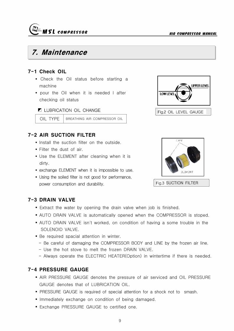
MSL COMPRESSOR AIR COMPRESSOR MANUAL
9
7 Maintenance
7-1 Check OIL
Check the Oil status before starting a
machine
pour the Oil when it is needed l after
checking oil status
OIL TYPE BREATHING AIR COMPRESSOR OIL
7-2 AIR SUCTION FILTER
Install the suction filter on the outside
Filter the dust of air
Use the ELEMENT after cleaning when it is
dirty
exchange ELEMENT when it is impossible to use
Using the soiled filter is not good for performance
power consumption and durability
7-3 DRAIN VALVE
Extract the water by opening the drain valve when job is finished
AUTO DRAIN VALVE is automatically opened when the COMPRESSOR is stoped
AUTO DRAIN VALVE isnt worked on condition of having a some trouble in the
SOLENOID VALVE
Be required spacial attention in winter
- Be careful of damaging the COMPRESSOR BODY and LINE by the frozen air line
- Use the hot stove to melt the frozen DRAIN VALVE
- Always operate the ELECTRIC HEATER(Option) in wintertime if there is needed
7-4 PRESSURE GAUGE
AIR PRESSURE GAUGE denotes the pressure of air serviced and OIL PRESSURE
GAUGE denotes that of LUBRICATION OIL
PRESSURE GAUGE is required of special attention for a shock not to smash
Immediately exchange on condition of being damaged
Exchange PRESSURE GAUGE to certified one
SUCTION FILTER
MSL COMPRESSOR AIR COMPRESSOR MANUAL
10
7-5 SAFETY VALVE
SAFETY VALVE protects the machine for the higher pressure than settled pressure
Must be careful of the safety valve
Must be careful of the enclosed SAFETY VALVE
Immediately exchange the damaged SAFETY VALVE
In case of changing for a safety valve you must contact with a manufacturer
Do not touch SAFETY VALVE without manufacturers authorization
Only skilled engineer can regulate safety valves setting pressure
(Caution Never exceed over 110 of rated pressure)
SAFETY VALVE TYPE-I
High pressure settingTurn the PRESSURE ADJUST SCREW to CW①after loosening the LOCK NUT②Turn the LOCK NUT to CWafter setting②the pressure watching the Pressure gauge
Low pressure setting
Turn the PRESSURE ADJUST SCREW toCCW①after loosening the LOCK NUT②Turn the LOCK NUT toCW after setting②the pressure watching the pressure gauge
SAFETY VALVE TYPE-Ⅱ
High pressure setting
Turn the PRESSURE ADJUST SCREW to① CWafter loosening the LOCK NUT②Turn the LOCK NUT toCW after adjusting②the pressure watching the pressure gauge
Low pressure settingTurn the PRESSURE ADJUST SCREW to CCW①after loosening the LOCK NUT②Turn the LOCK NUT toCW after adjusting②the pressure watching the pressure gauge
FIG5 TYPE-Ⅱ
FIG4 SAFETY VALVE
TYPE-I
MSL COMPRESSOR AIR COMPRESSOR MANUAL
11
7-6 Other safety Device
PRESSURE SWITCH
Can stop running of compressor in case of over pressured situation
CCW PRESSURE UP CW (CLOCKWISE)
CW PRESSURE DOWN CCW (COUNTER CLOCKWISE)
THERMAL RELAY
- In case of the motors being stopped by overload settle the problem and
press the reset bar then relay will run because relay is standardized by the reset
method of hand-operated
- Check the screw and Fasten it per 4 months
- Clean electromagnetic contact surface per 4 months to remove the reason of noise
- Adjust control circuits voltage to rated voltage of operating coil as exactly as
possible
7-7 MOTOR
Checking points
- Check if the motor shaft can smoothly rotate by the hand or not
- Check The Belt tension and specifications in case of exchanging it
- Check if the power supply(Voltage Frequency Phase)is conform to name plate
- Power connections are performed after verifying the conformity with that of
name plate
Check during Operation
- The operating current of continually used motor must be lower than marked
(name plate) current If the operating current is higher than marked current
check the motor
- In order to check the rotation direction and wiring operate motor under no
loading
- If the rotating direction is reversed interchange two lines among three lines
FIG6 PRESSURE SW
MSL COMPRESSOR AIR COMPRESSOR MANUAL
12
7-8 AIR CLEANING FILTER
Compressed air is purified by filter so you must change filter per every 50 hours
The filter is consist of three small size (1 2 3 step filtering) or big one size
(1 step filtering)
In case of the filter of small sizes change
A and B step filter with new one and
one step filter can be reused by cleaning
Change filter
- Turn the filter case to CCW with supplied
filter opener and resolve it
- Change new one after cleaning the inner space
- Carefully turn the filter case to CW not to
damage the o-ring
① ② ③ ④ ⑤
7-9 Checking items after operation
Must open the drain valve after compressing operation to drain compressed water
Compressor heated is needed for changing compressor oil
FIG7 AIR CLEANING
FILTER
MSL COMPRESSOR AIR COMPRESSOR MANUAL
13
7-10 Ambient conditions for preservation
Operate compressor at least 10 minutes per a week because Compressors not
running for a long time causes a failure of the machine
Keep the compressor being covered indoor where is dry and clean
Always clean the COMPRESSOR
Check the compressor periodically with maintenance table or decrease of life time
and bad performance will be caused
In case of keeping of COMPRESSOR in damp condition for a long time it needs
unloaded rotation to get compressor oil into the cylinder after removing of the filter
A compressor installed with UNLOAD EQUIPMENT needs oil lubrication after
removing of connection nipple
7-11 V-belt tension
Readjust new V-belt after the first 25 operating hours
The best tension for a belt drive is the lowest possible where the belt under
full load does not slip
A rough value for this is when the belt deflects 10 when pressed with thumb
pressure between the two pulleys
FIG8 BELT TENSION
10 mm
MSL COMPRESSOR AIR COMPRESSOR MANUAL
14
7-12 Torque sequence
Lighten valve head and cylinder boltsnuts equally in the sequence shown in
figuration
FIG9 TORQUE SEQUENCE
7-13 Tightening torque values
Unless otherwise specified in text the following torque values apply
All valve head screws require torque wrench tightening
The indicated torque values are valid for bolts in greased condition
Replace self-retaining nuts on reassembly
BOLT TYPE BOLT SIZE MAX TORQUE
HEXAGON BOLT M6 10 Nm
HEXAGON BOLT M8 25 Nm
HEXAGON BOLT M10 45 Nm
HEXAGON BOLT M12 75 Nm
HEXAGON BOLT M14 120 Nm
HEXAGON BOLT M16 200 Nm
7-14 CLEAN SEPARATOR
Remove and clean sintered filter element as follows or exchange it if completely
clogged
Remove piping connected to filter head Remove filter head along with sintered
filter element
Remove centre screw and separate sintered filter element baffle and vortex
plate from the filter head
To clean filter element use hot soapy water and blow dry with compressed air
MSL COMPRESSOR AIR COMPRESSOR MANUAL
15
8 Troubleshooting
Problem Reason Action
No rotation1Burn out of cylinderand piston
Service to manufacturer
COMPRESSOR overheat
1Failure of ventvalve2Obstructed suctionfilter
Change valve
Clean and change of filter
Fill up time is too long
1Failure of suction valve2Air line leakage3Failure of nipple4Obstructed suction filter5Failure of unload valve
Change valve Change the line with air leakage Check the nipple Clean and change of suction filter Applied lubrication oil after removement of unload nipple
Abnormal noise
1Worn down2Shortage of oil3Obstructed suction filter
Change parts Supply oil Check filter
No rotation of MOTOR
1A stoppage of electriccurrent2A break in a wire3Failure of motor starter4Bad contacting
Check the incoming wire connection Check wire disconnection Check the contact point Fasten the terminal screw Check switch
Overheated motor
1Overload2Fluctuation of Supplingvoltage and Frequency3Over voltage and voltagedips4Dad cooling
Check the rated current Check the voltage and frequency
Clean the cooling area
Reverse rotation ofmotor
1Main power supplyconnection error
Check the 3phase sequence
Can not startengine(In case of usingengine instead ofmotor)
1Discharged battery2Bad contact of electricequipment3Failure of start motor4Bad contact5Failure of generator
Fasten terminal screw fully Check switch function
Check power cable Change generator Refer to the engine manual
Electrical error
1Unexpected protectivefunction(Turn-off) of NFB
2Malfunctioning ofpressure switch
Check short-circuit Overload(Rating and setting of overcorrect protectivedevices)
Check power wire Check air line Check selected pressure Change PRESSURE SWITCH
Failure of autodrain valve
1Malfunctioning of solvalve
2Malfunctioning ofautomatic drain valve
Change SOLENOID VALVE Obstructed air line by ingress of solid bodies and liquids(Clean the line)
Check the line in the wintertime against rupture by freezing Check the wiring Ingress of solid bodies and liquids(Clean up everything) In the wintertime obstructed air line by freezing(Melt by Hot air gun)
Check air line
Failure of safetyvalve
1Ingress of external solidbodies and liquids
Clean up the ingress of solid bodies and liquids Change safety valve
AIR condensationtime is too long
1 Check the air line leakage(Verify the air line leakage under main power off afterrise up air line pressure at 150
2 Check the air leak about drain during operating conditionIf there air leakage detected change SOLENOID VALVE
3 Check the third and fourth step head and pipe NIPPLE
MSL COMPRESSOR AIR COMPRESSOR MANUAL
16
9 Preventive Maintenance
ACTIONPERIOD
TIMEHOUR DAY WEEK MONTH
QUAR-TER
HALF-YEAR YEAR
2YEAR
Clean and assembling condition
(each part of compressor)
Check CRANK CASE OIL
Check DRAIN VALVE
Check AIR leakage
Check PRESSURE GAUGE
Check PRESSURE Switch
Clean SUCTION FILTER
Check SAFETY VALVE
Check BELT tension
Change SUCTION FILTER
Check SUCTION amp DISCHARGE VALVE
CheckChange OIL FILTER ELEMENT
Change CRANK CASE OIL 50
Change DISCHARGE FILTER ELEMENT 50
Check SEPARATOR
Clean SEPARATOR
Check piston ring
MSL COMPRESSOR AIR COMPRESSOR MANUAL
P A R T L IS TMODEL MSF-300
MSL COMPRESSOR Co LtdHEAD OFFICE TEL 82 31 541 7000 FAX 82 31 542 2999HOME httpwwwmslcompcom
MSL COMPRESSOR AIR COMPRESSOR MANUAL
18
MSL COMPRESSOR AIR COMPRESSOR MANUAL
B HEAD ASSY
MSL COMPRESSOR AIR COMPRESSOR MANUAL
B HEAD ASSYKEY No PART No DESCRIPTION (Qty) NOTE
01 B-300-A-001 CRANK CASE
02 B-300-A-002 OIL GAUGE
03 B-300-F-001 SNAP RING
04 B-300-A-003 CRANK SHAFT
05 B-300-A-004 KEY
06 6306 BEARING
07 B-300-G-001 GASKET
08 B-300-A-005 BEARING COVER
09 B-300-A-006 OIL SEAL
10 6305ZZ BEARING
11 B-300-A-007 PULLEY
12 B-300-B-001 WASHER
13 B-300-B-002 BOLT
14 B-300-A-008 1 STAGE CONNECTION ROD
15 B-300-A-009 1 STAGE PISTON
16 B-300-A-010 1 STAGE PISTON PIN
17 B-300-F-002 SNAP RING
18 B-300-H-001 1 STAGE PISTON RING SET
19 B-300-G-002 GASKET
20 B-300-A-011 1 STAGE CYLINDER
21 B-300-B-003 SPRING WASHER
22 B-300-B-004 BOLT
23 B-300-G-003 GASKET
24 B-300-A-012 1 STAGE SUCTION amp DISCHARGE VALVE
25 B-300-B-005 BOLT
26 B-300-G-004 1 STAGE CYLINDER HEAD
26-1 B-300-G-004-1 BOLT
27 B-300-A-041 BOLT
28 B-300-A-042 GASKET
29 B-300-A-043 CAP NUT
MSL COMPRESSOR AIR COMPRESSOR MANUAL
B-B HEAD ASSYKEY No PART No DESCRIPTION (Qty) NOTE
30 B-300-A-014 2 STAGE CONNECTION ROD
30-1 B-300-A-014-1 3 STAGE CONNECTION ROD
31 B-300-A-015 23 STAGE PISTON PIN
32 B-300-A-016 2 STAGE PISTON
32-1 B-300-A-016-1 2 STAGE PISTON RING
33 B-300-G-005 GASKET
34 B-300-A-017 2 STAGE CYLINDER
35 B-300-G-005 GASKET
36 B-300-H-004 2 STAGE SD VALVE
37 B-300-A-018 2 STAGE CYLINDER HEAD
38 B-300-B-006 BOLT
39 B-300-A-019 3 STAGE PISTON
40 B-300-G-006 GASKET
41 B-300-A-020 3 STAGE CYLINDER
42 B-300-H-005 3 STAGE SD VALVE
43 B-300-A-021 3 STAGE CYLINDER HEAD
44 B-300-B-007 SPRING WASHER
45 B-300-B-008 BOLT
46 B-300-A-035 3 STAGE SPARE PISTON
47 B-300-A-036 2 STAGE SLEEVE
48 B-300-A-037 3 STAGE SLEEVE
49 HK3516 BEARING
50 HK1616B BEARING
51 B-300-A-038 2 STAGE VALVE BODY
52 B-300-A-039 3 STAGE VALVE BODY
53 B-300-A-040 SLEEVE HEAD GUARD
MSL COMPRESSOR AIR COMPRESSOR MANUAL
C 1 2 STAGE FILTER SETS
MSL COMPRESSOR AIR COMPRESSOR MANUAL
C 12 STAGE FILTER SETSKEY No PART No DESCRIPTION (Qty) NOTE
01 B-300-A-028 BODY
02 B-300-A-029 1 STAGE FILTER DOWN CAP
03 B-300-F-005 O-RING
04 B-300-A-030 1 STAGE FILTER ELEMENT
05 B-300-H-015 1 STAGE FILTER ELEMENT SET
06 B-300-H-016 1 STAGE FILTER DOWN CAP SET
07 B-300-F-006 O-RING
08 B-300-B-017 ALLEN SCREW
09 B-300-B-018 WASHER
10 B-300-B-019 SPRING WASHER
11 B-300-A-031 DRAIN VALVE
12 B-300-A-032 2 STAGE FILTER DOWN CAP
13 B-300-H-017 2 STAGE FILTER DOWN CAP SET
14 B-300-A-033 2 STAGE FILTER ELEMENT
15 B-300-H-018 2 STAGE FILTER ELEMENT SET
16 B-300-B-020 ALLEN SCREW
MSL COMPRESSOR AIR COMPRESSOR MANUAL
D AIR COOLING SYSTEM
MSL COMPRESSOR AIR COMPRESSOR MANUAL
D AIR COOLING SYSTEMKEY No PART No DESCRIPTION (Qty) NOTE
01 B-300-H-001 1 STAGE INTER COOLER SET 4
02 B-300-H-002 2 STAGE INTER COOLER SET 2
03 B-300-H-003 AFTER COOLER SET 2
04 B-300-H-004 AIR CONNECTING PIPE SET 4
05 B-300-H-005 CONNECTOR 7
06 B-300-H-006 CONNECTOR 2
07 B-300-H-007 CONNECTOR 2
08 B-300-B-008 SAFETY VALVE 1
09 B-300-B-009 CONNECTOR 1
MSL COMPRESSOR AIR COMPRESSOR MANUAL
E SEPARATOR SET
MSL COMPRESSOR AIR COMPRESSOR MANUAL
E SEPARATOR SETKEY No PART No DESCRIPTION (Qty) NOTE
01 B-300-A-023 BODY
02 B-300-A-024 SEPARATOR DOWN CAP
03 B-300-F-003 O-RING
04 B-300-H-013 SEPARATOR DOWN CAP SET
05 B-300-A-024 DRAIN VALVE
06 B-300-B-013 ALLEN SCREW
07 B-300-B-014 WASHER
08 B-300-B-015 SPRING WASHER
09 B-300-A-025 BOTTOM COVER
10 B-300-A-026 BEADS
11 B-300-A-027 TOP COVER
12 B-300-F-004 SPRING
13 B-300-H-014 ELEMENT SET
14 B-300-B-016 ALLEN SCREW
MSL COMPRESSOR AIR COMPRESSOR MANUAL
MSL COMPRESSOR AIR COMPRESSOR MANUAL
MSL COMPRESSOR AIR COMPRESSOR MANUAL
MSL COMPRESSOR AIR COMPRESSOR MANUAL
MEMO
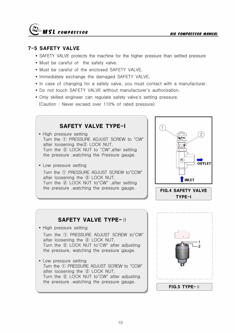
MSL COMPRESSOR AIR COMPRESSOR MANUAL
10
7-5 SAFETY VALVE
SAFETY VALVE protects the machine for the higher pressure than settled pressure
Must be careful of the safety valve
Must be careful of the enclosed SAFETY VALVE
Immediately exchange the damaged SAFETY VALVE
In case of changing for a safety valve you must contact with a manufacturer
Do not touch SAFETY VALVE without manufacturers authorization
Only skilled engineer can regulate safety valves setting pressure
(Caution Never exceed over 110 of rated pressure)
SAFETY VALVE TYPE-I
High pressure settingTurn the PRESSURE ADJUST SCREW to CW①after loosening the LOCK NUT②Turn the LOCK NUT to CWafter setting②the pressure watching the Pressure gauge
Low pressure setting
Turn the PRESSURE ADJUST SCREW toCCW①after loosening the LOCK NUT②Turn the LOCK NUT toCW after setting②the pressure watching the pressure gauge
SAFETY VALVE TYPE-Ⅱ
High pressure setting
Turn the PRESSURE ADJUST SCREW to① CWafter loosening the LOCK NUT②Turn the LOCK NUT toCW after adjusting②the pressure watching the pressure gauge
Low pressure settingTurn the PRESSURE ADJUST SCREW to CCW①after loosening the LOCK NUT②Turn the LOCK NUT toCW after adjusting②the pressure watching the pressure gauge
FIG5 TYPE-Ⅱ
FIG4 SAFETY VALVE
TYPE-I
MSL COMPRESSOR AIR COMPRESSOR MANUAL
11
7-6 Other safety Device
PRESSURE SWITCH
Can stop running of compressor in case of over pressured situation
CCW PRESSURE UP CW (CLOCKWISE)
CW PRESSURE DOWN CCW (COUNTER CLOCKWISE)
THERMAL RELAY
- In case of the motors being stopped by overload settle the problem and
press the reset bar then relay will run because relay is standardized by the reset
method of hand-operated
- Check the screw and Fasten it per 4 months
- Clean electromagnetic contact surface per 4 months to remove the reason of noise
- Adjust control circuits voltage to rated voltage of operating coil as exactly as
possible
7-7 MOTOR
Checking points
- Check if the motor shaft can smoothly rotate by the hand or not
- Check The Belt tension and specifications in case of exchanging it
- Check if the power supply(Voltage Frequency Phase)is conform to name plate
- Power connections are performed after verifying the conformity with that of
name plate
Check during Operation
- The operating current of continually used motor must be lower than marked
(name plate) current If the operating current is higher than marked current
check the motor
- In order to check the rotation direction and wiring operate motor under no
loading
- If the rotating direction is reversed interchange two lines among three lines
FIG6 PRESSURE SW
MSL COMPRESSOR AIR COMPRESSOR MANUAL
12
7-8 AIR CLEANING FILTER
Compressed air is purified by filter so you must change filter per every 50 hours
The filter is consist of three small size (1 2 3 step filtering) or big one size
(1 step filtering)
In case of the filter of small sizes change
A and B step filter with new one and
one step filter can be reused by cleaning
Change filter
- Turn the filter case to CCW with supplied
filter opener and resolve it
- Change new one after cleaning the inner space
- Carefully turn the filter case to CW not to
damage the o-ring
① ② ③ ④ ⑤
7-9 Checking items after operation
Must open the drain valve after compressing operation to drain compressed water
Compressor heated is needed for changing compressor oil
FIG7 AIR CLEANING
FILTER
MSL COMPRESSOR AIR COMPRESSOR MANUAL
13
7-10 Ambient conditions for preservation
Operate compressor at least 10 minutes per a week because Compressors not
running for a long time causes a failure of the machine
Keep the compressor being covered indoor where is dry and clean
Always clean the COMPRESSOR
Check the compressor periodically with maintenance table or decrease of life time
and bad performance will be caused
In case of keeping of COMPRESSOR in damp condition for a long time it needs
unloaded rotation to get compressor oil into the cylinder after removing of the filter
A compressor installed with UNLOAD EQUIPMENT needs oil lubrication after
removing of connection nipple
7-11 V-belt tension
Readjust new V-belt after the first 25 operating hours
The best tension for a belt drive is the lowest possible where the belt under
full load does not slip
A rough value for this is when the belt deflects 10 when pressed with thumb
pressure between the two pulleys
FIG8 BELT TENSION
10 mm
MSL COMPRESSOR AIR COMPRESSOR MANUAL
14
7-12 Torque sequence
Lighten valve head and cylinder boltsnuts equally in the sequence shown in
figuration
FIG9 TORQUE SEQUENCE
7-13 Tightening torque values
Unless otherwise specified in text the following torque values apply
All valve head screws require torque wrench tightening
The indicated torque values are valid for bolts in greased condition
Replace self-retaining nuts on reassembly
BOLT TYPE BOLT SIZE MAX TORQUE
HEXAGON BOLT M6 10 Nm
HEXAGON BOLT M8 25 Nm
HEXAGON BOLT M10 45 Nm
HEXAGON BOLT M12 75 Nm
HEXAGON BOLT M14 120 Nm
HEXAGON BOLT M16 200 Nm
7-14 CLEAN SEPARATOR
Remove and clean sintered filter element as follows or exchange it if completely
clogged
Remove piping connected to filter head Remove filter head along with sintered
filter element
Remove centre screw and separate sintered filter element baffle and vortex
plate from the filter head
To clean filter element use hot soapy water and blow dry with compressed air
MSL COMPRESSOR AIR COMPRESSOR MANUAL
15
8 Troubleshooting
Problem Reason Action
No rotation1Burn out of cylinderand piston
Service to manufacturer
COMPRESSOR overheat
1Failure of ventvalve2Obstructed suctionfilter
Change valve
Clean and change of filter
Fill up time is too long
1Failure of suction valve2Air line leakage3Failure of nipple4Obstructed suction filter5Failure of unload valve
Change valve Change the line with air leakage Check the nipple Clean and change of suction filter Applied lubrication oil after removement of unload nipple
Abnormal noise
1Worn down2Shortage of oil3Obstructed suction filter
Change parts Supply oil Check filter
No rotation of MOTOR
1A stoppage of electriccurrent2A break in a wire3Failure of motor starter4Bad contacting
Check the incoming wire connection Check wire disconnection Check the contact point Fasten the terminal screw Check switch
Overheated motor
1Overload2Fluctuation of Supplingvoltage and Frequency3Over voltage and voltagedips4Dad cooling
Check the rated current Check the voltage and frequency
Clean the cooling area
Reverse rotation ofmotor
1Main power supplyconnection error
Check the 3phase sequence
Can not startengine(In case of usingengine instead ofmotor)
1Discharged battery2Bad contact of electricequipment3Failure of start motor4Bad contact5Failure of generator
Fasten terminal screw fully Check switch function
Check power cable Change generator Refer to the engine manual
Electrical error
1Unexpected protectivefunction(Turn-off) of NFB
2Malfunctioning ofpressure switch
Check short-circuit Overload(Rating and setting of overcorrect protectivedevices)
Check power wire Check air line Check selected pressure Change PRESSURE SWITCH
Failure of autodrain valve
1Malfunctioning of solvalve
2Malfunctioning ofautomatic drain valve
Change SOLENOID VALVE Obstructed air line by ingress of solid bodies and liquids(Clean the line)
Check the line in the wintertime against rupture by freezing Check the wiring Ingress of solid bodies and liquids(Clean up everything) In the wintertime obstructed air line by freezing(Melt by Hot air gun)
Check air line
Failure of safetyvalve
1Ingress of external solidbodies and liquids
Clean up the ingress of solid bodies and liquids Change safety valve
AIR condensationtime is too long
1 Check the air line leakage(Verify the air line leakage under main power off afterrise up air line pressure at 150
2 Check the air leak about drain during operating conditionIf there air leakage detected change SOLENOID VALVE
3 Check the third and fourth step head and pipe NIPPLE
MSL COMPRESSOR AIR COMPRESSOR MANUAL
16
9 Preventive Maintenance
ACTIONPERIOD
TIMEHOUR DAY WEEK MONTH
QUAR-TER
HALF-YEAR YEAR
2YEAR
Clean and assembling condition
(each part of compressor)
Check CRANK CASE OIL
Check DRAIN VALVE
Check AIR leakage
Check PRESSURE GAUGE
Check PRESSURE Switch
Clean SUCTION FILTER
Check SAFETY VALVE
Check BELT tension
Change SUCTION FILTER
Check SUCTION amp DISCHARGE VALVE
CheckChange OIL FILTER ELEMENT
Change CRANK CASE OIL 50
Change DISCHARGE FILTER ELEMENT 50
Check SEPARATOR
Clean SEPARATOR
Check piston ring
MSL COMPRESSOR AIR COMPRESSOR MANUAL
P A R T L IS TMODEL MSF-300
MSL COMPRESSOR Co LtdHEAD OFFICE TEL 82 31 541 7000 FAX 82 31 542 2999HOME httpwwwmslcompcom
MSL COMPRESSOR AIR COMPRESSOR MANUAL
18
MSL COMPRESSOR AIR COMPRESSOR MANUAL
B HEAD ASSY
MSL COMPRESSOR AIR COMPRESSOR MANUAL
B HEAD ASSYKEY No PART No DESCRIPTION (Qty) NOTE
01 B-300-A-001 CRANK CASE
02 B-300-A-002 OIL GAUGE
03 B-300-F-001 SNAP RING
04 B-300-A-003 CRANK SHAFT
05 B-300-A-004 KEY
06 6306 BEARING
07 B-300-G-001 GASKET
08 B-300-A-005 BEARING COVER
09 B-300-A-006 OIL SEAL
10 6305ZZ BEARING
11 B-300-A-007 PULLEY
12 B-300-B-001 WASHER
13 B-300-B-002 BOLT
14 B-300-A-008 1 STAGE CONNECTION ROD
15 B-300-A-009 1 STAGE PISTON
16 B-300-A-010 1 STAGE PISTON PIN
17 B-300-F-002 SNAP RING
18 B-300-H-001 1 STAGE PISTON RING SET
19 B-300-G-002 GASKET
20 B-300-A-011 1 STAGE CYLINDER
21 B-300-B-003 SPRING WASHER
22 B-300-B-004 BOLT
23 B-300-G-003 GASKET
24 B-300-A-012 1 STAGE SUCTION amp DISCHARGE VALVE
25 B-300-B-005 BOLT
26 B-300-G-004 1 STAGE CYLINDER HEAD
26-1 B-300-G-004-1 BOLT
27 B-300-A-041 BOLT
28 B-300-A-042 GASKET
29 B-300-A-043 CAP NUT
MSL COMPRESSOR AIR COMPRESSOR MANUAL
B-B HEAD ASSYKEY No PART No DESCRIPTION (Qty) NOTE
30 B-300-A-014 2 STAGE CONNECTION ROD
30-1 B-300-A-014-1 3 STAGE CONNECTION ROD
31 B-300-A-015 23 STAGE PISTON PIN
32 B-300-A-016 2 STAGE PISTON
32-1 B-300-A-016-1 2 STAGE PISTON RING
33 B-300-G-005 GASKET
34 B-300-A-017 2 STAGE CYLINDER
35 B-300-G-005 GASKET
36 B-300-H-004 2 STAGE SD VALVE
37 B-300-A-018 2 STAGE CYLINDER HEAD
38 B-300-B-006 BOLT
39 B-300-A-019 3 STAGE PISTON
40 B-300-G-006 GASKET
41 B-300-A-020 3 STAGE CYLINDER
42 B-300-H-005 3 STAGE SD VALVE
43 B-300-A-021 3 STAGE CYLINDER HEAD
44 B-300-B-007 SPRING WASHER
45 B-300-B-008 BOLT
46 B-300-A-035 3 STAGE SPARE PISTON
47 B-300-A-036 2 STAGE SLEEVE
48 B-300-A-037 3 STAGE SLEEVE
49 HK3516 BEARING
50 HK1616B BEARING
51 B-300-A-038 2 STAGE VALVE BODY
52 B-300-A-039 3 STAGE VALVE BODY
53 B-300-A-040 SLEEVE HEAD GUARD
MSL COMPRESSOR AIR COMPRESSOR MANUAL
C 1 2 STAGE FILTER SETS
MSL COMPRESSOR AIR COMPRESSOR MANUAL
C 12 STAGE FILTER SETSKEY No PART No DESCRIPTION (Qty) NOTE
01 B-300-A-028 BODY
02 B-300-A-029 1 STAGE FILTER DOWN CAP
03 B-300-F-005 O-RING
04 B-300-A-030 1 STAGE FILTER ELEMENT
05 B-300-H-015 1 STAGE FILTER ELEMENT SET
06 B-300-H-016 1 STAGE FILTER DOWN CAP SET
07 B-300-F-006 O-RING
08 B-300-B-017 ALLEN SCREW
09 B-300-B-018 WASHER
10 B-300-B-019 SPRING WASHER
11 B-300-A-031 DRAIN VALVE
12 B-300-A-032 2 STAGE FILTER DOWN CAP
13 B-300-H-017 2 STAGE FILTER DOWN CAP SET
14 B-300-A-033 2 STAGE FILTER ELEMENT
15 B-300-H-018 2 STAGE FILTER ELEMENT SET
16 B-300-B-020 ALLEN SCREW
MSL COMPRESSOR AIR COMPRESSOR MANUAL
D AIR COOLING SYSTEM
MSL COMPRESSOR AIR COMPRESSOR MANUAL
D AIR COOLING SYSTEMKEY No PART No DESCRIPTION (Qty) NOTE
01 B-300-H-001 1 STAGE INTER COOLER SET 4
02 B-300-H-002 2 STAGE INTER COOLER SET 2
03 B-300-H-003 AFTER COOLER SET 2
04 B-300-H-004 AIR CONNECTING PIPE SET 4
05 B-300-H-005 CONNECTOR 7
06 B-300-H-006 CONNECTOR 2
07 B-300-H-007 CONNECTOR 2
08 B-300-B-008 SAFETY VALVE 1
09 B-300-B-009 CONNECTOR 1
MSL COMPRESSOR AIR COMPRESSOR MANUAL
E SEPARATOR SET
MSL COMPRESSOR AIR COMPRESSOR MANUAL
E SEPARATOR SETKEY No PART No DESCRIPTION (Qty) NOTE
01 B-300-A-023 BODY
02 B-300-A-024 SEPARATOR DOWN CAP
03 B-300-F-003 O-RING
04 B-300-H-013 SEPARATOR DOWN CAP SET
05 B-300-A-024 DRAIN VALVE
06 B-300-B-013 ALLEN SCREW
07 B-300-B-014 WASHER
08 B-300-B-015 SPRING WASHER
09 B-300-A-025 BOTTOM COVER
10 B-300-A-026 BEADS
11 B-300-A-027 TOP COVER
12 B-300-F-004 SPRING
13 B-300-H-014 ELEMENT SET
14 B-300-B-016 ALLEN SCREW
MSL COMPRESSOR AIR COMPRESSOR MANUAL
MSL COMPRESSOR AIR COMPRESSOR MANUAL
MSL COMPRESSOR AIR COMPRESSOR MANUAL
MSL COMPRESSOR AIR COMPRESSOR MANUAL
MEMO
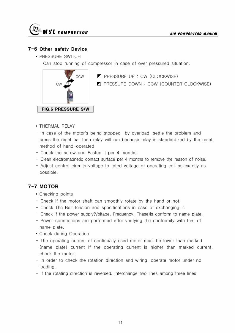
MSL COMPRESSOR AIR COMPRESSOR MANUAL
11
7-6 Other safety Device
PRESSURE SWITCH
Can stop running of compressor in case of over pressured situation
CCW PRESSURE UP CW (CLOCKWISE)
CW PRESSURE DOWN CCW (COUNTER CLOCKWISE)
THERMAL RELAY
- In case of the motors being stopped by overload settle the problem and
press the reset bar then relay will run because relay is standardized by the reset
method of hand-operated
- Check the screw and Fasten it per 4 months
- Clean electromagnetic contact surface per 4 months to remove the reason of noise
- Adjust control circuits voltage to rated voltage of operating coil as exactly as
possible
7-7 MOTOR
Checking points
- Check if the motor shaft can smoothly rotate by the hand or not
- Check The Belt tension and specifications in case of exchanging it
- Check if the power supply(Voltage Frequency Phase)is conform to name plate
- Power connections are performed after verifying the conformity with that of
name plate
Check during Operation
- The operating current of continually used motor must be lower than marked
(name plate) current If the operating current is higher than marked current
check the motor
- In order to check the rotation direction and wiring operate motor under no
loading
- If the rotating direction is reversed interchange two lines among three lines
FIG6 PRESSURE SW
MSL COMPRESSOR AIR COMPRESSOR MANUAL
12
7-8 AIR CLEANING FILTER
Compressed air is purified by filter so you must change filter per every 50 hours
The filter is consist of three small size (1 2 3 step filtering) or big one size
(1 step filtering)
In case of the filter of small sizes change
A and B step filter with new one and
one step filter can be reused by cleaning
Change filter
- Turn the filter case to CCW with supplied
filter opener and resolve it
- Change new one after cleaning the inner space
- Carefully turn the filter case to CW not to
damage the o-ring
① ② ③ ④ ⑤
7-9 Checking items after operation
Must open the drain valve after compressing operation to drain compressed water
Compressor heated is needed for changing compressor oil
FIG7 AIR CLEANING
FILTER
MSL COMPRESSOR AIR COMPRESSOR MANUAL
13
7-10 Ambient conditions for preservation
Operate compressor at least 10 minutes per a week because Compressors not
running for a long time causes a failure of the machine
Keep the compressor being covered indoor where is dry and clean
Always clean the COMPRESSOR
Check the compressor periodically with maintenance table or decrease of life time
and bad performance will be caused
In case of keeping of COMPRESSOR in damp condition for a long time it needs
unloaded rotation to get compressor oil into the cylinder after removing of the filter
A compressor installed with UNLOAD EQUIPMENT needs oil lubrication after
removing of connection nipple
7-11 V-belt tension
Readjust new V-belt after the first 25 operating hours
The best tension for a belt drive is the lowest possible where the belt under
full load does not slip
A rough value for this is when the belt deflects 10 when pressed with thumb
pressure between the two pulleys
FIG8 BELT TENSION
10 mm
MSL COMPRESSOR AIR COMPRESSOR MANUAL
14
7-12 Torque sequence
Lighten valve head and cylinder boltsnuts equally in the sequence shown in
figuration
FIG9 TORQUE SEQUENCE
7-13 Tightening torque values
Unless otherwise specified in text the following torque values apply
All valve head screws require torque wrench tightening
The indicated torque values are valid for bolts in greased condition
Replace self-retaining nuts on reassembly
BOLT TYPE BOLT SIZE MAX TORQUE
HEXAGON BOLT M6 10 Nm
HEXAGON BOLT M8 25 Nm
HEXAGON BOLT M10 45 Nm
HEXAGON BOLT M12 75 Nm
HEXAGON BOLT M14 120 Nm
HEXAGON BOLT M16 200 Nm
7-14 CLEAN SEPARATOR
Remove and clean sintered filter element as follows or exchange it if completely
clogged
Remove piping connected to filter head Remove filter head along with sintered
filter element
Remove centre screw and separate sintered filter element baffle and vortex
plate from the filter head
To clean filter element use hot soapy water and blow dry with compressed air
MSL COMPRESSOR AIR COMPRESSOR MANUAL
15
8 Troubleshooting
Problem Reason Action
No rotation1Burn out of cylinderand piston
Service to manufacturer
COMPRESSOR overheat
1Failure of ventvalve2Obstructed suctionfilter
Change valve
Clean and change of filter
Fill up time is too long
1Failure of suction valve2Air line leakage3Failure of nipple4Obstructed suction filter5Failure of unload valve
Change valve Change the line with air leakage Check the nipple Clean and change of suction filter Applied lubrication oil after removement of unload nipple
Abnormal noise
1Worn down2Shortage of oil3Obstructed suction filter
Change parts Supply oil Check filter
No rotation of MOTOR
1A stoppage of electriccurrent2A break in a wire3Failure of motor starter4Bad contacting
Check the incoming wire connection Check wire disconnection Check the contact point Fasten the terminal screw Check switch
Overheated motor
1Overload2Fluctuation of Supplingvoltage and Frequency3Over voltage and voltagedips4Dad cooling
Check the rated current Check the voltage and frequency
Clean the cooling area
Reverse rotation ofmotor
1Main power supplyconnection error
Check the 3phase sequence
Can not startengine(In case of usingengine instead ofmotor)
1Discharged battery2Bad contact of electricequipment3Failure of start motor4Bad contact5Failure of generator
Fasten terminal screw fully Check switch function
Check power cable Change generator Refer to the engine manual
Electrical error
1Unexpected protectivefunction(Turn-off) of NFB
2Malfunctioning ofpressure switch
Check short-circuit Overload(Rating and setting of overcorrect protectivedevices)
Check power wire Check air line Check selected pressure Change PRESSURE SWITCH
Failure of autodrain valve
1Malfunctioning of solvalve
2Malfunctioning ofautomatic drain valve
Change SOLENOID VALVE Obstructed air line by ingress of solid bodies and liquids(Clean the line)
Check the line in the wintertime against rupture by freezing Check the wiring Ingress of solid bodies and liquids(Clean up everything) In the wintertime obstructed air line by freezing(Melt by Hot air gun)
Check air line
Failure of safetyvalve
1Ingress of external solidbodies and liquids
Clean up the ingress of solid bodies and liquids Change safety valve
AIR condensationtime is too long
1 Check the air line leakage(Verify the air line leakage under main power off afterrise up air line pressure at 150
2 Check the air leak about drain during operating conditionIf there air leakage detected change SOLENOID VALVE
3 Check the third and fourth step head and pipe NIPPLE
MSL COMPRESSOR AIR COMPRESSOR MANUAL
16
9 Preventive Maintenance
ACTIONPERIOD
TIMEHOUR DAY WEEK MONTH
QUAR-TER
HALF-YEAR YEAR
2YEAR
Clean and assembling condition
(each part of compressor)
Check CRANK CASE OIL
Check DRAIN VALVE
Check AIR leakage
Check PRESSURE GAUGE
Check PRESSURE Switch
Clean SUCTION FILTER
Check SAFETY VALVE
Check BELT tension
Change SUCTION FILTER
Check SUCTION amp DISCHARGE VALVE
CheckChange OIL FILTER ELEMENT
Change CRANK CASE OIL 50
Change DISCHARGE FILTER ELEMENT 50
Check SEPARATOR
Clean SEPARATOR
Check piston ring
MSL COMPRESSOR AIR COMPRESSOR MANUAL
P A R T L IS TMODEL MSF-300
MSL COMPRESSOR Co LtdHEAD OFFICE TEL 82 31 541 7000 FAX 82 31 542 2999HOME httpwwwmslcompcom
MSL COMPRESSOR AIR COMPRESSOR MANUAL
18
MSL COMPRESSOR AIR COMPRESSOR MANUAL
B HEAD ASSY
MSL COMPRESSOR AIR COMPRESSOR MANUAL
B HEAD ASSYKEY No PART No DESCRIPTION (Qty) NOTE
01 B-300-A-001 CRANK CASE
02 B-300-A-002 OIL GAUGE
03 B-300-F-001 SNAP RING
04 B-300-A-003 CRANK SHAFT
05 B-300-A-004 KEY
06 6306 BEARING
07 B-300-G-001 GASKET
08 B-300-A-005 BEARING COVER
09 B-300-A-006 OIL SEAL
10 6305ZZ BEARING
11 B-300-A-007 PULLEY
12 B-300-B-001 WASHER
13 B-300-B-002 BOLT
14 B-300-A-008 1 STAGE CONNECTION ROD
15 B-300-A-009 1 STAGE PISTON
16 B-300-A-010 1 STAGE PISTON PIN
17 B-300-F-002 SNAP RING
18 B-300-H-001 1 STAGE PISTON RING SET
19 B-300-G-002 GASKET
20 B-300-A-011 1 STAGE CYLINDER
21 B-300-B-003 SPRING WASHER
22 B-300-B-004 BOLT
23 B-300-G-003 GASKET
24 B-300-A-012 1 STAGE SUCTION amp DISCHARGE VALVE
25 B-300-B-005 BOLT
26 B-300-G-004 1 STAGE CYLINDER HEAD
26-1 B-300-G-004-1 BOLT
27 B-300-A-041 BOLT
28 B-300-A-042 GASKET
29 B-300-A-043 CAP NUT
MSL COMPRESSOR AIR COMPRESSOR MANUAL
B-B HEAD ASSYKEY No PART No DESCRIPTION (Qty) NOTE
30 B-300-A-014 2 STAGE CONNECTION ROD
30-1 B-300-A-014-1 3 STAGE CONNECTION ROD
31 B-300-A-015 23 STAGE PISTON PIN
32 B-300-A-016 2 STAGE PISTON
32-1 B-300-A-016-1 2 STAGE PISTON RING
33 B-300-G-005 GASKET
34 B-300-A-017 2 STAGE CYLINDER
35 B-300-G-005 GASKET
36 B-300-H-004 2 STAGE SD VALVE
37 B-300-A-018 2 STAGE CYLINDER HEAD
38 B-300-B-006 BOLT
39 B-300-A-019 3 STAGE PISTON
40 B-300-G-006 GASKET
41 B-300-A-020 3 STAGE CYLINDER
42 B-300-H-005 3 STAGE SD VALVE
43 B-300-A-021 3 STAGE CYLINDER HEAD
44 B-300-B-007 SPRING WASHER
45 B-300-B-008 BOLT
46 B-300-A-035 3 STAGE SPARE PISTON
47 B-300-A-036 2 STAGE SLEEVE
48 B-300-A-037 3 STAGE SLEEVE
49 HK3516 BEARING
50 HK1616B BEARING
51 B-300-A-038 2 STAGE VALVE BODY
52 B-300-A-039 3 STAGE VALVE BODY
53 B-300-A-040 SLEEVE HEAD GUARD
MSL COMPRESSOR AIR COMPRESSOR MANUAL
C 1 2 STAGE FILTER SETS
MSL COMPRESSOR AIR COMPRESSOR MANUAL
C 12 STAGE FILTER SETSKEY No PART No DESCRIPTION (Qty) NOTE
01 B-300-A-028 BODY
02 B-300-A-029 1 STAGE FILTER DOWN CAP
03 B-300-F-005 O-RING
04 B-300-A-030 1 STAGE FILTER ELEMENT
05 B-300-H-015 1 STAGE FILTER ELEMENT SET
06 B-300-H-016 1 STAGE FILTER DOWN CAP SET
07 B-300-F-006 O-RING
08 B-300-B-017 ALLEN SCREW
09 B-300-B-018 WASHER
10 B-300-B-019 SPRING WASHER
11 B-300-A-031 DRAIN VALVE
12 B-300-A-032 2 STAGE FILTER DOWN CAP
13 B-300-H-017 2 STAGE FILTER DOWN CAP SET
14 B-300-A-033 2 STAGE FILTER ELEMENT
15 B-300-H-018 2 STAGE FILTER ELEMENT SET
16 B-300-B-020 ALLEN SCREW
MSL COMPRESSOR AIR COMPRESSOR MANUAL
D AIR COOLING SYSTEM
MSL COMPRESSOR AIR COMPRESSOR MANUAL
D AIR COOLING SYSTEMKEY No PART No DESCRIPTION (Qty) NOTE
01 B-300-H-001 1 STAGE INTER COOLER SET 4
02 B-300-H-002 2 STAGE INTER COOLER SET 2
03 B-300-H-003 AFTER COOLER SET 2
04 B-300-H-004 AIR CONNECTING PIPE SET 4
05 B-300-H-005 CONNECTOR 7
06 B-300-H-006 CONNECTOR 2
07 B-300-H-007 CONNECTOR 2
08 B-300-B-008 SAFETY VALVE 1
09 B-300-B-009 CONNECTOR 1
MSL COMPRESSOR AIR COMPRESSOR MANUAL
E SEPARATOR SET
MSL COMPRESSOR AIR COMPRESSOR MANUAL
E SEPARATOR SETKEY No PART No DESCRIPTION (Qty) NOTE
01 B-300-A-023 BODY
02 B-300-A-024 SEPARATOR DOWN CAP
03 B-300-F-003 O-RING
04 B-300-H-013 SEPARATOR DOWN CAP SET
05 B-300-A-024 DRAIN VALVE
06 B-300-B-013 ALLEN SCREW
07 B-300-B-014 WASHER
08 B-300-B-015 SPRING WASHER
09 B-300-A-025 BOTTOM COVER
10 B-300-A-026 BEADS
11 B-300-A-027 TOP COVER
12 B-300-F-004 SPRING
13 B-300-H-014 ELEMENT SET
14 B-300-B-016 ALLEN SCREW
MSL COMPRESSOR AIR COMPRESSOR MANUAL
MSL COMPRESSOR AIR COMPRESSOR MANUAL
MSL COMPRESSOR AIR COMPRESSOR MANUAL
MSL COMPRESSOR AIR COMPRESSOR MANUAL
MEMO
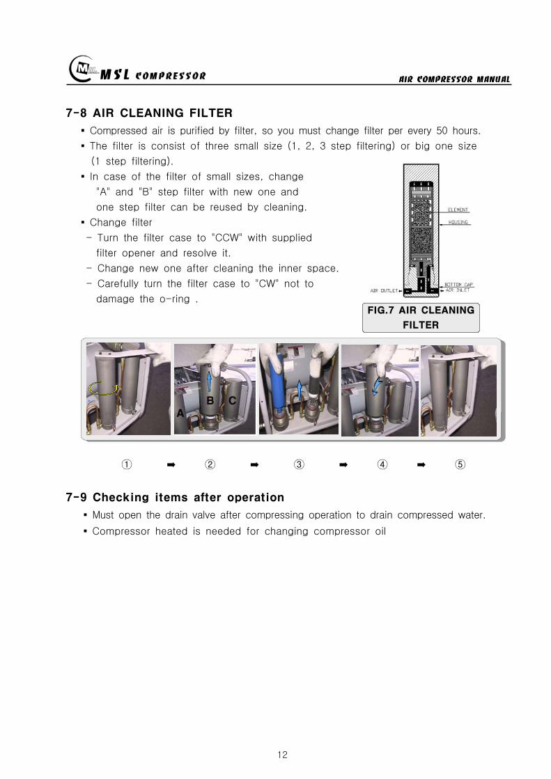
MSL COMPRESSOR AIR COMPRESSOR MANUAL
12
7-8 AIR CLEANING FILTER
Compressed air is purified by filter so you must change filter per every 50 hours
The filter is consist of three small size (1 2 3 step filtering) or big one size
(1 step filtering)
In case of the filter of small sizes change
A and B step filter with new one and
one step filter can be reused by cleaning
Change filter
- Turn the filter case to CCW with supplied
filter opener and resolve it
- Change new one after cleaning the inner space
- Carefully turn the filter case to CW not to
damage the o-ring
① ② ③ ④ ⑤
7-9 Checking items after operation
Must open the drain valve after compressing operation to drain compressed water
Compressor heated is needed for changing compressor oil
FIG7 AIR CLEANING
FILTER
MSL COMPRESSOR AIR COMPRESSOR MANUAL
13
7-10 Ambient conditions for preservation
Operate compressor at least 10 minutes per a week because Compressors not
running for a long time causes a failure of the machine
Keep the compressor being covered indoor where is dry and clean
Always clean the COMPRESSOR
Check the compressor periodically with maintenance table or decrease of life time
and bad performance will be caused
In case of keeping of COMPRESSOR in damp condition for a long time it needs
unloaded rotation to get compressor oil into the cylinder after removing of the filter
A compressor installed with UNLOAD EQUIPMENT needs oil lubrication after
removing of connection nipple
7-11 V-belt tension
Readjust new V-belt after the first 25 operating hours
The best tension for a belt drive is the lowest possible where the belt under
full load does not slip
A rough value for this is when the belt deflects 10 when pressed with thumb
pressure between the two pulleys
FIG8 BELT TENSION
10 mm
MSL COMPRESSOR AIR COMPRESSOR MANUAL
14
7-12 Torque sequence
Lighten valve head and cylinder boltsnuts equally in the sequence shown in
figuration
FIG9 TORQUE SEQUENCE
7-13 Tightening torque values
Unless otherwise specified in text the following torque values apply
All valve head screws require torque wrench tightening
The indicated torque values are valid for bolts in greased condition
Replace self-retaining nuts on reassembly
BOLT TYPE BOLT SIZE MAX TORQUE
HEXAGON BOLT M6 10 Nm
HEXAGON BOLT M8 25 Nm
HEXAGON BOLT M10 45 Nm
HEXAGON BOLT M12 75 Nm
HEXAGON BOLT M14 120 Nm
HEXAGON BOLT M16 200 Nm
7-14 CLEAN SEPARATOR
Remove and clean sintered filter element as follows or exchange it if completely
clogged
Remove piping connected to filter head Remove filter head along with sintered
filter element
Remove centre screw and separate sintered filter element baffle and vortex
plate from the filter head
To clean filter element use hot soapy water and blow dry with compressed air
MSL COMPRESSOR AIR COMPRESSOR MANUAL
15
8 Troubleshooting
Problem Reason Action
No rotation1Burn out of cylinderand piston
Service to manufacturer
COMPRESSOR overheat
1Failure of ventvalve2Obstructed suctionfilter
Change valve
Clean and change of filter
Fill up time is too long
1Failure of suction valve2Air line leakage3Failure of nipple4Obstructed suction filter5Failure of unload valve
Change valve Change the line with air leakage Check the nipple Clean and change of suction filter Applied lubrication oil after removement of unload nipple
Abnormal noise
1Worn down2Shortage of oil3Obstructed suction filter
Change parts Supply oil Check filter
No rotation of MOTOR
1A stoppage of electriccurrent2A break in a wire3Failure of motor starter4Bad contacting
Check the incoming wire connection Check wire disconnection Check the contact point Fasten the terminal screw Check switch
Overheated motor
1Overload2Fluctuation of Supplingvoltage and Frequency3Over voltage and voltagedips4Dad cooling
Check the rated current Check the voltage and frequency
Clean the cooling area
Reverse rotation ofmotor
1Main power supplyconnection error
Check the 3phase sequence
Can not startengine(In case of usingengine instead ofmotor)
1Discharged battery2Bad contact of electricequipment3Failure of start motor4Bad contact5Failure of generator
Fasten terminal screw fully Check switch function
Check power cable Change generator Refer to the engine manual
Electrical error
1Unexpected protectivefunction(Turn-off) of NFB
2Malfunctioning ofpressure switch
Check short-circuit Overload(Rating and setting of overcorrect protectivedevices)
Check power wire Check air line Check selected pressure Change PRESSURE SWITCH
Failure of autodrain valve
1Malfunctioning of solvalve
2Malfunctioning ofautomatic drain valve
Change SOLENOID VALVE Obstructed air line by ingress of solid bodies and liquids(Clean the line)
Check the line in the wintertime against rupture by freezing Check the wiring Ingress of solid bodies and liquids(Clean up everything) In the wintertime obstructed air line by freezing(Melt by Hot air gun)
Check air line
Failure of safetyvalve
1Ingress of external solidbodies and liquids
Clean up the ingress of solid bodies and liquids Change safety valve
AIR condensationtime is too long
1 Check the air line leakage(Verify the air line leakage under main power off afterrise up air line pressure at 150
2 Check the air leak about drain during operating conditionIf there air leakage detected change SOLENOID VALVE
3 Check the third and fourth step head and pipe NIPPLE
MSL COMPRESSOR AIR COMPRESSOR MANUAL
16
9 Preventive Maintenance
ACTIONPERIOD
TIMEHOUR DAY WEEK MONTH
QUAR-TER
HALF-YEAR YEAR
2YEAR
Clean and assembling condition
(each part of compressor)
Check CRANK CASE OIL
Check DRAIN VALVE
Check AIR leakage
Check PRESSURE GAUGE
Check PRESSURE Switch
Clean SUCTION FILTER
Check SAFETY VALVE
Check BELT tension
Change SUCTION FILTER
Check SUCTION amp DISCHARGE VALVE
CheckChange OIL FILTER ELEMENT
Change CRANK CASE OIL 50
Change DISCHARGE FILTER ELEMENT 50
Check SEPARATOR
Clean SEPARATOR
Check piston ring
MSL COMPRESSOR AIR COMPRESSOR MANUAL
P A R T L IS TMODEL MSF-300
MSL COMPRESSOR Co LtdHEAD OFFICE TEL 82 31 541 7000 FAX 82 31 542 2999HOME httpwwwmslcompcom
MSL COMPRESSOR AIR COMPRESSOR MANUAL
18
MSL COMPRESSOR AIR COMPRESSOR MANUAL
B HEAD ASSY
MSL COMPRESSOR AIR COMPRESSOR MANUAL
B HEAD ASSYKEY No PART No DESCRIPTION (Qty) NOTE
01 B-300-A-001 CRANK CASE
02 B-300-A-002 OIL GAUGE
03 B-300-F-001 SNAP RING
04 B-300-A-003 CRANK SHAFT
05 B-300-A-004 KEY
06 6306 BEARING
07 B-300-G-001 GASKET
08 B-300-A-005 BEARING COVER
09 B-300-A-006 OIL SEAL
10 6305ZZ BEARING
11 B-300-A-007 PULLEY
12 B-300-B-001 WASHER
13 B-300-B-002 BOLT
14 B-300-A-008 1 STAGE CONNECTION ROD
15 B-300-A-009 1 STAGE PISTON
16 B-300-A-010 1 STAGE PISTON PIN
17 B-300-F-002 SNAP RING
18 B-300-H-001 1 STAGE PISTON RING SET
19 B-300-G-002 GASKET
20 B-300-A-011 1 STAGE CYLINDER
21 B-300-B-003 SPRING WASHER
22 B-300-B-004 BOLT
23 B-300-G-003 GASKET
24 B-300-A-012 1 STAGE SUCTION amp DISCHARGE VALVE
25 B-300-B-005 BOLT
26 B-300-G-004 1 STAGE CYLINDER HEAD
26-1 B-300-G-004-1 BOLT
27 B-300-A-041 BOLT
28 B-300-A-042 GASKET
29 B-300-A-043 CAP NUT
MSL COMPRESSOR AIR COMPRESSOR MANUAL
B-B HEAD ASSYKEY No PART No DESCRIPTION (Qty) NOTE
30 B-300-A-014 2 STAGE CONNECTION ROD
30-1 B-300-A-014-1 3 STAGE CONNECTION ROD
31 B-300-A-015 23 STAGE PISTON PIN
32 B-300-A-016 2 STAGE PISTON
32-1 B-300-A-016-1 2 STAGE PISTON RING
33 B-300-G-005 GASKET
34 B-300-A-017 2 STAGE CYLINDER
35 B-300-G-005 GASKET
36 B-300-H-004 2 STAGE SD VALVE
37 B-300-A-018 2 STAGE CYLINDER HEAD
38 B-300-B-006 BOLT
39 B-300-A-019 3 STAGE PISTON
40 B-300-G-006 GASKET
41 B-300-A-020 3 STAGE CYLINDER
42 B-300-H-005 3 STAGE SD VALVE
43 B-300-A-021 3 STAGE CYLINDER HEAD
44 B-300-B-007 SPRING WASHER
45 B-300-B-008 BOLT
46 B-300-A-035 3 STAGE SPARE PISTON
47 B-300-A-036 2 STAGE SLEEVE
48 B-300-A-037 3 STAGE SLEEVE
49 HK3516 BEARING
50 HK1616B BEARING
51 B-300-A-038 2 STAGE VALVE BODY
52 B-300-A-039 3 STAGE VALVE BODY
53 B-300-A-040 SLEEVE HEAD GUARD
MSL COMPRESSOR AIR COMPRESSOR MANUAL
C 1 2 STAGE FILTER SETS
MSL COMPRESSOR AIR COMPRESSOR MANUAL
C 12 STAGE FILTER SETSKEY No PART No DESCRIPTION (Qty) NOTE
01 B-300-A-028 BODY
02 B-300-A-029 1 STAGE FILTER DOWN CAP
03 B-300-F-005 O-RING
04 B-300-A-030 1 STAGE FILTER ELEMENT
05 B-300-H-015 1 STAGE FILTER ELEMENT SET
06 B-300-H-016 1 STAGE FILTER DOWN CAP SET
07 B-300-F-006 O-RING
08 B-300-B-017 ALLEN SCREW
09 B-300-B-018 WASHER
10 B-300-B-019 SPRING WASHER
11 B-300-A-031 DRAIN VALVE
12 B-300-A-032 2 STAGE FILTER DOWN CAP
13 B-300-H-017 2 STAGE FILTER DOWN CAP SET
14 B-300-A-033 2 STAGE FILTER ELEMENT
15 B-300-H-018 2 STAGE FILTER ELEMENT SET
16 B-300-B-020 ALLEN SCREW
MSL COMPRESSOR AIR COMPRESSOR MANUAL
D AIR COOLING SYSTEM
MSL COMPRESSOR AIR COMPRESSOR MANUAL
D AIR COOLING SYSTEMKEY No PART No DESCRIPTION (Qty) NOTE
01 B-300-H-001 1 STAGE INTER COOLER SET 4
02 B-300-H-002 2 STAGE INTER COOLER SET 2
03 B-300-H-003 AFTER COOLER SET 2
04 B-300-H-004 AIR CONNECTING PIPE SET 4
05 B-300-H-005 CONNECTOR 7
06 B-300-H-006 CONNECTOR 2
07 B-300-H-007 CONNECTOR 2
08 B-300-B-008 SAFETY VALVE 1
09 B-300-B-009 CONNECTOR 1
MSL COMPRESSOR AIR COMPRESSOR MANUAL
E SEPARATOR SET
MSL COMPRESSOR AIR COMPRESSOR MANUAL
E SEPARATOR SETKEY No PART No DESCRIPTION (Qty) NOTE
01 B-300-A-023 BODY
02 B-300-A-024 SEPARATOR DOWN CAP
03 B-300-F-003 O-RING
04 B-300-H-013 SEPARATOR DOWN CAP SET
05 B-300-A-024 DRAIN VALVE
06 B-300-B-013 ALLEN SCREW
07 B-300-B-014 WASHER
08 B-300-B-015 SPRING WASHER
09 B-300-A-025 BOTTOM COVER
10 B-300-A-026 BEADS
11 B-300-A-027 TOP COVER
12 B-300-F-004 SPRING
13 B-300-H-014 ELEMENT SET
14 B-300-B-016 ALLEN SCREW
MSL COMPRESSOR AIR COMPRESSOR MANUAL
MSL COMPRESSOR AIR COMPRESSOR MANUAL
MSL COMPRESSOR AIR COMPRESSOR MANUAL
MSL COMPRESSOR AIR COMPRESSOR MANUAL
MEMO
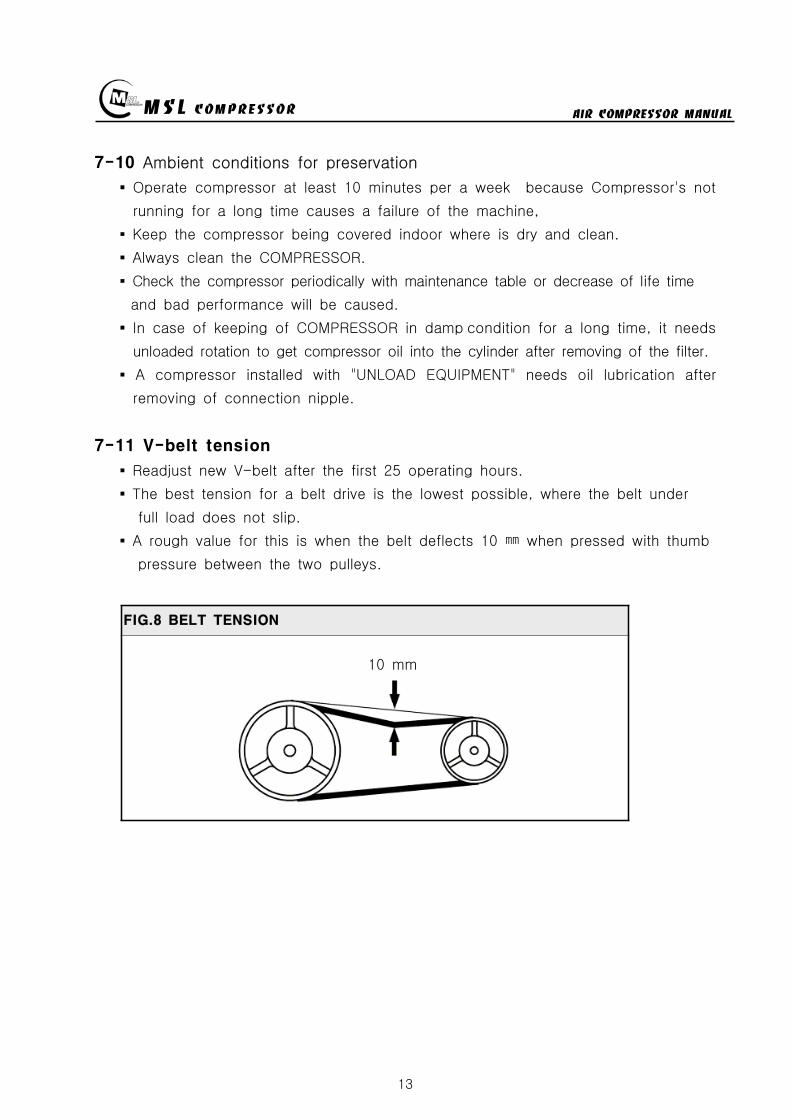
MSL COMPRESSOR AIR COMPRESSOR MANUAL
13
7-10 Ambient conditions for preservation
Operate compressor at least 10 minutes per a week because Compressors not
running for a long time causes a failure of the machine
Keep the compressor being covered indoor where is dry and clean
Always clean the COMPRESSOR
Check the compressor periodically with maintenance table or decrease of life time
and bad performance will be caused
In case of keeping of COMPRESSOR in damp condition for a long time it needs
unloaded rotation to get compressor oil into the cylinder after removing of the filter
A compressor installed with UNLOAD EQUIPMENT needs oil lubrication after
removing of connection nipple
7-11 V-belt tension
Readjust new V-belt after the first 25 operating hours
The best tension for a belt drive is the lowest possible where the belt under
full load does not slip
A rough value for this is when the belt deflects 10 when pressed with thumb
pressure between the two pulleys
FIG8 BELT TENSION
10 mm
MSL COMPRESSOR AIR COMPRESSOR MANUAL
14
7-12 Torque sequence
Lighten valve head and cylinder boltsnuts equally in the sequence shown in
figuration
FIG9 TORQUE SEQUENCE
7-13 Tightening torque values
Unless otherwise specified in text the following torque values apply
All valve head screws require torque wrench tightening
The indicated torque values are valid for bolts in greased condition
Replace self-retaining nuts on reassembly
BOLT TYPE BOLT SIZE MAX TORQUE
HEXAGON BOLT M6 10 Nm
HEXAGON BOLT M8 25 Nm
HEXAGON BOLT M10 45 Nm
HEXAGON BOLT M12 75 Nm
HEXAGON BOLT M14 120 Nm
HEXAGON BOLT M16 200 Nm
7-14 CLEAN SEPARATOR
Remove and clean sintered filter element as follows or exchange it if completely
clogged
Remove piping connected to filter head Remove filter head along with sintered
filter element
Remove centre screw and separate sintered filter element baffle and vortex
plate from the filter head
To clean filter element use hot soapy water and blow dry with compressed air
MSL COMPRESSOR AIR COMPRESSOR MANUAL
15
8 Troubleshooting
Problem Reason Action
No rotation1Burn out of cylinderand piston
Service to manufacturer
COMPRESSOR overheat
1Failure of ventvalve2Obstructed suctionfilter
Change valve
Clean and change of filter
Fill up time is too long
1Failure of suction valve2Air line leakage3Failure of nipple4Obstructed suction filter5Failure of unload valve
Change valve Change the line with air leakage Check the nipple Clean and change of suction filter Applied lubrication oil after removement of unload nipple
Abnormal noise
1Worn down2Shortage of oil3Obstructed suction filter
Change parts Supply oil Check filter
No rotation of MOTOR
1A stoppage of electriccurrent2A break in a wire3Failure of motor starter4Bad contacting
Check the incoming wire connection Check wire disconnection Check the contact point Fasten the terminal screw Check switch
Overheated motor
1Overload2Fluctuation of Supplingvoltage and Frequency3Over voltage and voltagedips4Dad cooling
Check the rated current Check the voltage and frequency
Clean the cooling area
Reverse rotation ofmotor
1Main power supplyconnection error
Check the 3phase sequence
Can not startengine(In case of usingengine instead ofmotor)
1Discharged battery2Bad contact of electricequipment3Failure of start motor4Bad contact5Failure of generator
Fasten terminal screw fully Check switch function
Check power cable Change generator Refer to the engine manual
Electrical error
1Unexpected protectivefunction(Turn-off) of NFB
2Malfunctioning ofpressure switch
Check short-circuit Overload(Rating and setting of overcorrect protectivedevices)
Check power wire Check air line Check selected pressure Change PRESSURE SWITCH
Failure of autodrain valve
1Malfunctioning of solvalve
2Malfunctioning ofautomatic drain valve
Change SOLENOID VALVE Obstructed air line by ingress of solid bodies and liquids(Clean the line)
Check the line in the wintertime against rupture by freezing Check the wiring Ingress of solid bodies and liquids(Clean up everything) In the wintertime obstructed air line by freezing(Melt by Hot air gun)
Check air line
Failure of safetyvalve
1Ingress of external solidbodies and liquids
Clean up the ingress of solid bodies and liquids Change safety valve
AIR condensationtime is too long
1 Check the air line leakage(Verify the air line leakage under main power off afterrise up air line pressure at 150
2 Check the air leak about drain during operating conditionIf there air leakage detected change SOLENOID VALVE
3 Check the third and fourth step head and pipe NIPPLE
MSL COMPRESSOR AIR COMPRESSOR MANUAL
16
9 Preventive Maintenance
ACTIONPERIOD
TIMEHOUR DAY WEEK MONTH
QUAR-TER
HALF-YEAR YEAR
2YEAR
Clean and assembling condition
(each part of compressor)
Check CRANK CASE OIL
Check DRAIN VALVE
Check AIR leakage
Check PRESSURE GAUGE
Check PRESSURE Switch
Clean SUCTION FILTER
Check SAFETY VALVE
Check BELT tension
Change SUCTION FILTER
Check SUCTION amp DISCHARGE VALVE
CheckChange OIL FILTER ELEMENT
Change CRANK CASE OIL 50
Change DISCHARGE FILTER ELEMENT 50
Check SEPARATOR
Clean SEPARATOR
Check piston ring
MSL COMPRESSOR AIR COMPRESSOR MANUAL
P A R T L IS TMODEL MSF-300
MSL COMPRESSOR Co LtdHEAD OFFICE TEL 82 31 541 7000 FAX 82 31 542 2999HOME httpwwwmslcompcom
MSL COMPRESSOR AIR COMPRESSOR MANUAL
18
MSL COMPRESSOR AIR COMPRESSOR MANUAL
B HEAD ASSY
MSL COMPRESSOR AIR COMPRESSOR MANUAL
B HEAD ASSYKEY No PART No DESCRIPTION (Qty) NOTE
01 B-300-A-001 CRANK CASE
02 B-300-A-002 OIL GAUGE
03 B-300-F-001 SNAP RING
04 B-300-A-003 CRANK SHAFT
05 B-300-A-004 KEY
06 6306 BEARING
07 B-300-G-001 GASKET
08 B-300-A-005 BEARING COVER
09 B-300-A-006 OIL SEAL
10 6305ZZ BEARING
11 B-300-A-007 PULLEY
12 B-300-B-001 WASHER
13 B-300-B-002 BOLT
14 B-300-A-008 1 STAGE CONNECTION ROD
15 B-300-A-009 1 STAGE PISTON
16 B-300-A-010 1 STAGE PISTON PIN
17 B-300-F-002 SNAP RING
18 B-300-H-001 1 STAGE PISTON RING SET
19 B-300-G-002 GASKET
20 B-300-A-011 1 STAGE CYLINDER
21 B-300-B-003 SPRING WASHER
22 B-300-B-004 BOLT
23 B-300-G-003 GASKET
24 B-300-A-012 1 STAGE SUCTION amp DISCHARGE VALVE
25 B-300-B-005 BOLT
26 B-300-G-004 1 STAGE CYLINDER HEAD
26-1 B-300-G-004-1 BOLT
27 B-300-A-041 BOLT
28 B-300-A-042 GASKET
29 B-300-A-043 CAP NUT
MSL COMPRESSOR AIR COMPRESSOR MANUAL
B-B HEAD ASSYKEY No PART No DESCRIPTION (Qty) NOTE
30 B-300-A-014 2 STAGE CONNECTION ROD
30-1 B-300-A-014-1 3 STAGE CONNECTION ROD
31 B-300-A-015 23 STAGE PISTON PIN
32 B-300-A-016 2 STAGE PISTON
32-1 B-300-A-016-1 2 STAGE PISTON RING
33 B-300-G-005 GASKET
34 B-300-A-017 2 STAGE CYLINDER
35 B-300-G-005 GASKET
36 B-300-H-004 2 STAGE SD VALVE
37 B-300-A-018 2 STAGE CYLINDER HEAD
38 B-300-B-006 BOLT
39 B-300-A-019 3 STAGE PISTON
40 B-300-G-006 GASKET
41 B-300-A-020 3 STAGE CYLINDER
42 B-300-H-005 3 STAGE SD VALVE
43 B-300-A-021 3 STAGE CYLINDER HEAD
44 B-300-B-007 SPRING WASHER
45 B-300-B-008 BOLT
46 B-300-A-035 3 STAGE SPARE PISTON
47 B-300-A-036 2 STAGE SLEEVE
48 B-300-A-037 3 STAGE SLEEVE
49 HK3516 BEARING
50 HK1616B BEARING
51 B-300-A-038 2 STAGE VALVE BODY
52 B-300-A-039 3 STAGE VALVE BODY
53 B-300-A-040 SLEEVE HEAD GUARD
MSL COMPRESSOR AIR COMPRESSOR MANUAL
C 1 2 STAGE FILTER SETS
MSL COMPRESSOR AIR COMPRESSOR MANUAL
C 12 STAGE FILTER SETSKEY No PART No DESCRIPTION (Qty) NOTE
01 B-300-A-028 BODY
02 B-300-A-029 1 STAGE FILTER DOWN CAP
03 B-300-F-005 O-RING
04 B-300-A-030 1 STAGE FILTER ELEMENT
05 B-300-H-015 1 STAGE FILTER ELEMENT SET
06 B-300-H-016 1 STAGE FILTER DOWN CAP SET
07 B-300-F-006 O-RING
08 B-300-B-017 ALLEN SCREW
09 B-300-B-018 WASHER
10 B-300-B-019 SPRING WASHER
11 B-300-A-031 DRAIN VALVE
12 B-300-A-032 2 STAGE FILTER DOWN CAP
13 B-300-H-017 2 STAGE FILTER DOWN CAP SET
14 B-300-A-033 2 STAGE FILTER ELEMENT
15 B-300-H-018 2 STAGE FILTER ELEMENT SET
16 B-300-B-020 ALLEN SCREW
MSL COMPRESSOR AIR COMPRESSOR MANUAL
D AIR COOLING SYSTEM
MSL COMPRESSOR AIR COMPRESSOR MANUAL
D AIR COOLING SYSTEMKEY No PART No DESCRIPTION (Qty) NOTE
01 B-300-H-001 1 STAGE INTER COOLER SET 4
02 B-300-H-002 2 STAGE INTER COOLER SET 2
03 B-300-H-003 AFTER COOLER SET 2
04 B-300-H-004 AIR CONNECTING PIPE SET 4
05 B-300-H-005 CONNECTOR 7
06 B-300-H-006 CONNECTOR 2
07 B-300-H-007 CONNECTOR 2
08 B-300-B-008 SAFETY VALVE 1
09 B-300-B-009 CONNECTOR 1
MSL COMPRESSOR AIR COMPRESSOR MANUAL
E SEPARATOR SET
MSL COMPRESSOR AIR COMPRESSOR MANUAL
E SEPARATOR SETKEY No PART No DESCRIPTION (Qty) NOTE
01 B-300-A-023 BODY
02 B-300-A-024 SEPARATOR DOWN CAP
03 B-300-F-003 O-RING
04 B-300-H-013 SEPARATOR DOWN CAP SET
05 B-300-A-024 DRAIN VALVE
06 B-300-B-013 ALLEN SCREW
07 B-300-B-014 WASHER
08 B-300-B-015 SPRING WASHER
09 B-300-A-025 BOTTOM COVER
10 B-300-A-026 BEADS
11 B-300-A-027 TOP COVER
12 B-300-F-004 SPRING
13 B-300-H-014 ELEMENT SET
14 B-300-B-016 ALLEN SCREW
MSL COMPRESSOR AIR COMPRESSOR MANUAL
MSL COMPRESSOR AIR COMPRESSOR MANUAL
MSL COMPRESSOR AIR COMPRESSOR MANUAL
MSL COMPRESSOR AIR COMPRESSOR MANUAL
MEMO
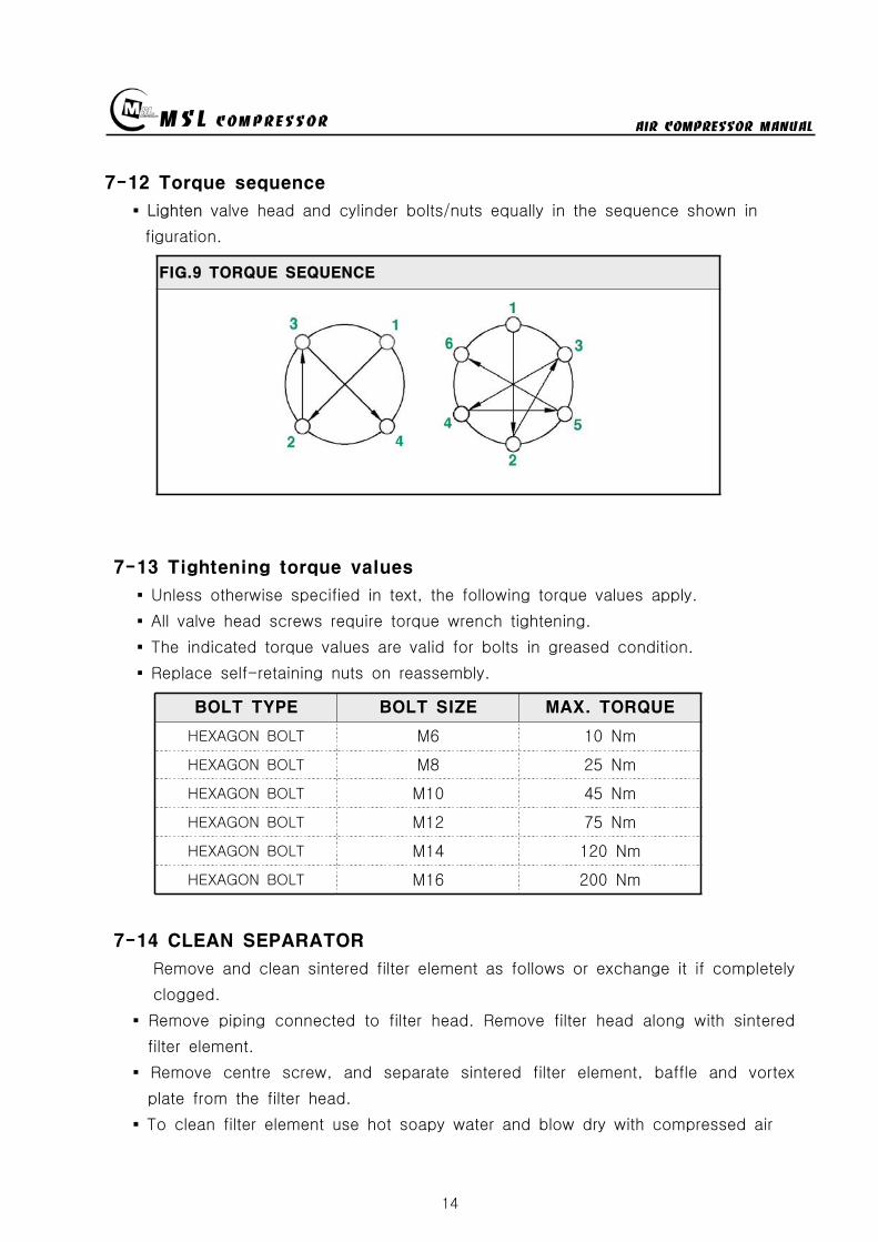
MSL COMPRESSOR AIR COMPRESSOR MANUAL
14
7-12 Torque sequence
Lighten valve head and cylinder boltsnuts equally in the sequence shown in
figuration
FIG9 TORQUE SEQUENCE
7-13 Tightening torque values
Unless otherwise specified in text the following torque values apply
All valve head screws require torque wrench tightening
The indicated torque values are valid for bolts in greased condition
Replace self-retaining nuts on reassembly
BOLT TYPE BOLT SIZE MAX TORQUE
HEXAGON BOLT M6 10 Nm
HEXAGON BOLT M8 25 Nm
HEXAGON BOLT M10 45 Nm
HEXAGON BOLT M12 75 Nm
HEXAGON BOLT M14 120 Nm
HEXAGON BOLT M16 200 Nm
7-14 CLEAN SEPARATOR
Remove and clean sintered filter element as follows or exchange it if completely
clogged
Remove piping connected to filter head Remove filter head along with sintered
filter element
Remove centre screw and separate sintered filter element baffle and vortex
plate from the filter head
To clean filter element use hot soapy water and blow dry with compressed air
MSL COMPRESSOR AIR COMPRESSOR MANUAL
15
8 Troubleshooting
Problem Reason Action
No rotation1Burn out of cylinderand piston
Service to manufacturer
COMPRESSOR overheat
1Failure of ventvalve2Obstructed suctionfilter
Change valve
Clean and change of filter
Fill up time is too long
1Failure of suction valve2Air line leakage3Failure of nipple4Obstructed suction filter5Failure of unload valve
Change valve Change the line with air leakage Check the nipple Clean and change of suction filter Applied lubrication oil after removement of unload nipple
Abnormal noise
1Worn down2Shortage of oil3Obstructed suction filter
Change parts Supply oil Check filter
No rotation of MOTOR
1A stoppage of electriccurrent2A break in a wire3Failure of motor starter4Bad contacting
Check the incoming wire connection Check wire disconnection Check the contact point Fasten the terminal screw Check switch
Overheated motor
1Overload2Fluctuation of Supplingvoltage and Frequency3Over voltage and voltagedips4Dad cooling
Check the rated current Check the voltage and frequency
Clean the cooling area
Reverse rotation ofmotor
1Main power supplyconnection error
Check the 3phase sequence
Can not startengine(In case of usingengine instead ofmotor)
1Discharged battery2Bad contact of electricequipment3Failure of start motor4Bad contact5Failure of generator
Fasten terminal screw fully Check switch function
Check power cable Change generator Refer to the engine manual
Electrical error
1Unexpected protectivefunction(Turn-off) of NFB
2Malfunctioning ofpressure switch
Check short-circuit Overload(Rating and setting of overcorrect protectivedevices)
Check power wire Check air line Check selected pressure Change PRESSURE SWITCH
Failure of autodrain valve
1Malfunctioning of solvalve
2Malfunctioning ofautomatic drain valve
Change SOLENOID VALVE Obstructed air line by ingress of solid bodies and liquids(Clean the line)
Check the line in the wintertime against rupture by freezing Check the wiring Ingress of solid bodies and liquids(Clean up everything) In the wintertime obstructed air line by freezing(Melt by Hot air gun)
Check air line
Failure of safetyvalve
1Ingress of external solidbodies and liquids
Clean up the ingress of solid bodies and liquids Change safety valve
AIR condensationtime is too long
1 Check the air line leakage(Verify the air line leakage under main power off afterrise up air line pressure at 150
2 Check the air leak about drain during operating conditionIf there air leakage detected change SOLENOID VALVE
3 Check the third and fourth step head and pipe NIPPLE
MSL COMPRESSOR AIR COMPRESSOR MANUAL
16
9 Preventive Maintenance
ACTIONPERIOD
TIMEHOUR DAY WEEK MONTH
QUAR-TER
HALF-YEAR YEAR
2YEAR
Clean and assembling condition
(each part of compressor)
Check CRANK CASE OIL
Check DRAIN VALVE
Check AIR leakage
Check PRESSURE GAUGE
Check PRESSURE Switch
Clean SUCTION FILTER
Check SAFETY VALVE
Check BELT tension
Change SUCTION FILTER
Check SUCTION amp DISCHARGE VALVE
CheckChange OIL FILTER ELEMENT
Change CRANK CASE OIL 50
Change DISCHARGE FILTER ELEMENT 50
Check SEPARATOR
Clean SEPARATOR
Check piston ring
MSL COMPRESSOR AIR COMPRESSOR MANUAL
P A R T L IS TMODEL MSF-300
MSL COMPRESSOR Co LtdHEAD OFFICE TEL 82 31 541 7000 FAX 82 31 542 2999HOME httpwwwmslcompcom
MSL COMPRESSOR AIR COMPRESSOR MANUAL
18
MSL COMPRESSOR AIR COMPRESSOR MANUAL
B HEAD ASSY
MSL COMPRESSOR AIR COMPRESSOR MANUAL
B HEAD ASSYKEY No PART No DESCRIPTION (Qty) NOTE
01 B-300-A-001 CRANK CASE
02 B-300-A-002 OIL GAUGE
03 B-300-F-001 SNAP RING
04 B-300-A-003 CRANK SHAFT
05 B-300-A-004 KEY
06 6306 BEARING
07 B-300-G-001 GASKET
08 B-300-A-005 BEARING COVER
09 B-300-A-006 OIL SEAL
10 6305ZZ BEARING
11 B-300-A-007 PULLEY
12 B-300-B-001 WASHER
13 B-300-B-002 BOLT
14 B-300-A-008 1 STAGE CONNECTION ROD
15 B-300-A-009 1 STAGE PISTON
16 B-300-A-010 1 STAGE PISTON PIN
17 B-300-F-002 SNAP RING
18 B-300-H-001 1 STAGE PISTON RING SET
19 B-300-G-002 GASKET
20 B-300-A-011 1 STAGE CYLINDER
21 B-300-B-003 SPRING WASHER
22 B-300-B-004 BOLT
23 B-300-G-003 GASKET
24 B-300-A-012 1 STAGE SUCTION amp DISCHARGE VALVE
25 B-300-B-005 BOLT
26 B-300-G-004 1 STAGE CYLINDER HEAD
26-1 B-300-G-004-1 BOLT
27 B-300-A-041 BOLT
28 B-300-A-042 GASKET
29 B-300-A-043 CAP NUT
MSL COMPRESSOR AIR COMPRESSOR MANUAL
B-B HEAD ASSYKEY No PART No DESCRIPTION (Qty) NOTE
30 B-300-A-014 2 STAGE CONNECTION ROD
30-1 B-300-A-014-1 3 STAGE CONNECTION ROD
31 B-300-A-015 23 STAGE PISTON PIN
32 B-300-A-016 2 STAGE PISTON
32-1 B-300-A-016-1 2 STAGE PISTON RING
33 B-300-G-005 GASKET
34 B-300-A-017 2 STAGE CYLINDER
35 B-300-G-005 GASKET
36 B-300-H-004 2 STAGE SD VALVE
37 B-300-A-018 2 STAGE CYLINDER HEAD
38 B-300-B-006 BOLT
39 B-300-A-019 3 STAGE PISTON
40 B-300-G-006 GASKET
41 B-300-A-020 3 STAGE CYLINDER
42 B-300-H-005 3 STAGE SD VALVE
43 B-300-A-021 3 STAGE CYLINDER HEAD
44 B-300-B-007 SPRING WASHER
45 B-300-B-008 BOLT
46 B-300-A-035 3 STAGE SPARE PISTON
47 B-300-A-036 2 STAGE SLEEVE
48 B-300-A-037 3 STAGE SLEEVE
49 HK3516 BEARING
50 HK1616B BEARING
51 B-300-A-038 2 STAGE VALVE BODY
52 B-300-A-039 3 STAGE VALVE BODY
53 B-300-A-040 SLEEVE HEAD GUARD
MSL COMPRESSOR AIR COMPRESSOR MANUAL
C 1 2 STAGE FILTER SETS
MSL COMPRESSOR AIR COMPRESSOR MANUAL
C 12 STAGE FILTER SETSKEY No PART No DESCRIPTION (Qty) NOTE
01 B-300-A-028 BODY
02 B-300-A-029 1 STAGE FILTER DOWN CAP
03 B-300-F-005 O-RING
04 B-300-A-030 1 STAGE FILTER ELEMENT
05 B-300-H-015 1 STAGE FILTER ELEMENT SET
06 B-300-H-016 1 STAGE FILTER DOWN CAP SET
07 B-300-F-006 O-RING
08 B-300-B-017 ALLEN SCREW
09 B-300-B-018 WASHER
10 B-300-B-019 SPRING WASHER
11 B-300-A-031 DRAIN VALVE
12 B-300-A-032 2 STAGE FILTER DOWN CAP
13 B-300-H-017 2 STAGE FILTER DOWN CAP SET
14 B-300-A-033 2 STAGE FILTER ELEMENT
15 B-300-H-018 2 STAGE FILTER ELEMENT SET
16 B-300-B-020 ALLEN SCREW
MSL COMPRESSOR AIR COMPRESSOR MANUAL
D AIR COOLING SYSTEM
MSL COMPRESSOR AIR COMPRESSOR MANUAL
D AIR COOLING SYSTEMKEY No PART No DESCRIPTION (Qty) NOTE
01 B-300-H-001 1 STAGE INTER COOLER SET 4
02 B-300-H-002 2 STAGE INTER COOLER SET 2
03 B-300-H-003 AFTER COOLER SET 2
04 B-300-H-004 AIR CONNECTING PIPE SET 4
05 B-300-H-005 CONNECTOR 7
06 B-300-H-006 CONNECTOR 2
07 B-300-H-007 CONNECTOR 2
08 B-300-B-008 SAFETY VALVE 1
09 B-300-B-009 CONNECTOR 1
MSL COMPRESSOR AIR COMPRESSOR MANUAL
E SEPARATOR SET
MSL COMPRESSOR AIR COMPRESSOR MANUAL
E SEPARATOR SETKEY No PART No DESCRIPTION (Qty) NOTE
01 B-300-A-023 BODY
02 B-300-A-024 SEPARATOR DOWN CAP
03 B-300-F-003 O-RING
04 B-300-H-013 SEPARATOR DOWN CAP SET
05 B-300-A-024 DRAIN VALVE
06 B-300-B-013 ALLEN SCREW
07 B-300-B-014 WASHER
08 B-300-B-015 SPRING WASHER
09 B-300-A-025 BOTTOM COVER
10 B-300-A-026 BEADS
11 B-300-A-027 TOP COVER
12 B-300-F-004 SPRING
13 B-300-H-014 ELEMENT SET
14 B-300-B-016 ALLEN SCREW
MSL COMPRESSOR AIR COMPRESSOR MANUAL
MSL COMPRESSOR AIR COMPRESSOR MANUAL
MSL COMPRESSOR AIR COMPRESSOR MANUAL
MSL COMPRESSOR AIR COMPRESSOR MANUAL
MEMO
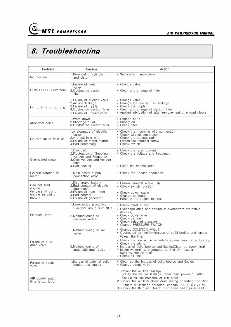
MSL COMPRESSOR AIR COMPRESSOR MANUAL
15
8 Troubleshooting
Problem Reason Action
No rotation1Burn out of cylinderand piston
Service to manufacturer
COMPRESSOR overheat
1Failure of ventvalve2Obstructed suctionfilter
Change valve
Clean and change of filter
Fill up time is too long
1Failure of suction valve2Air line leakage3Failure of nipple4Obstructed suction filter5Failure of unload valve
Change valve Change the line with air leakage Check the nipple Clean and change of suction filter Applied lubrication oil after removement of unload nipple
Abnormal noise
1Worn down2Shortage of oil3Obstructed suction filter
Change parts Supply oil Check filter
No rotation of MOTOR
1A stoppage of electriccurrent2A break in a wire3Failure of motor starter4Bad contacting
Check the incoming wire connection Check wire disconnection Check the contact point Fasten the terminal screw Check switch
Overheated motor
1Overload2Fluctuation of Supplingvoltage and Frequency3Over voltage and voltagedips4Dad cooling
Check the rated current Check the voltage and frequency
Clean the cooling area
Reverse rotation ofmotor
1Main power supplyconnection error
Check the 3phase sequence
Can not startengine(In case of usingengine instead ofmotor)
1Discharged battery2Bad contact of electricequipment3Failure of start motor4Bad contact5Failure of generator
Fasten terminal screw fully Check switch function
Check power cable Change generator Refer to the engine manual
Electrical error
1Unexpected protectivefunction(Turn-off) of NFB
2Malfunctioning ofpressure switch
Check short-circuit Overload(Rating and setting of overcorrect protectivedevices)
Check power wire Check air line Check selected pressure Change PRESSURE SWITCH
Failure of autodrain valve
1Malfunctioning of solvalve
2Malfunctioning ofautomatic drain valve
Change SOLENOID VALVE Obstructed air line by ingress of solid bodies and liquids(Clean the line)
Check the line in the wintertime against rupture by freezing Check the wiring Ingress of solid bodies and liquids(Clean up everything) In the wintertime obstructed air line by freezing(Melt by Hot air gun)
Check air line
Failure of safetyvalve
1Ingress of external solidbodies and liquids
Clean up the ingress of solid bodies and liquids Change safety valve
AIR condensationtime is too long
1 Check the air line leakage(Verify the air line leakage under main power off afterrise up air line pressure at 150
2 Check the air leak about drain during operating conditionIf there air leakage detected change SOLENOID VALVE
3 Check the third and fourth step head and pipe NIPPLE
MSL COMPRESSOR AIR COMPRESSOR MANUAL
16
9 Preventive Maintenance
ACTIONPERIOD
TIMEHOUR DAY WEEK MONTH
QUAR-TER
HALF-YEAR YEAR
2YEAR
Clean and assembling condition
(each part of compressor)
Check CRANK CASE OIL
Check DRAIN VALVE
Check AIR leakage
Check PRESSURE GAUGE
Check PRESSURE Switch
Clean SUCTION FILTER
Check SAFETY VALVE
Check BELT tension
Change SUCTION FILTER
Check SUCTION amp DISCHARGE VALVE
CheckChange OIL FILTER ELEMENT
Change CRANK CASE OIL 50
Change DISCHARGE FILTER ELEMENT 50
Check SEPARATOR
Clean SEPARATOR
Check piston ring
MSL COMPRESSOR AIR COMPRESSOR MANUAL
P A R T L IS TMODEL MSF-300
MSL COMPRESSOR Co LtdHEAD OFFICE TEL 82 31 541 7000 FAX 82 31 542 2999HOME httpwwwmslcompcom
MSL COMPRESSOR AIR COMPRESSOR MANUAL
18
MSL COMPRESSOR AIR COMPRESSOR MANUAL
B HEAD ASSY
MSL COMPRESSOR AIR COMPRESSOR MANUAL
B HEAD ASSYKEY No PART No DESCRIPTION (Qty) NOTE
01 B-300-A-001 CRANK CASE
02 B-300-A-002 OIL GAUGE
03 B-300-F-001 SNAP RING
04 B-300-A-003 CRANK SHAFT
05 B-300-A-004 KEY
06 6306 BEARING
07 B-300-G-001 GASKET
08 B-300-A-005 BEARING COVER
09 B-300-A-006 OIL SEAL
10 6305ZZ BEARING
11 B-300-A-007 PULLEY
12 B-300-B-001 WASHER
13 B-300-B-002 BOLT
14 B-300-A-008 1 STAGE CONNECTION ROD
15 B-300-A-009 1 STAGE PISTON
16 B-300-A-010 1 STAGE PISTON PIN
17 B-300-F-002 SNAP RING
18 B-300-H-001 1 STAGE PISTON RING SET
19 B-300-G-002 GASKET
20 B-300-A-011 1 STAGE CYLINDER
21 B-300-B-003 SPRING WASHER
22 B-300-B-004 BOLT
23 B-300-G-003 GASKET
24 B-300-A-012 1 STAGE SUCTION amp DISCHARGE VALVE
25 B-300-B-005 BOLT
26 B-300-G-004 1 STAGE CYLINDER HEAD
26-1 B-300-G-004-1 BOLT
27 B-300-A-041 BOLT
28 B-300-A-042 GASKET
29 B-300-A-043 CAP NUT
MSL COMPRESSOR AIR COMPRESSOR MANUAL
B-B HEAD ASSYKEY No PART No DESCRIPTION (Qty) NOTE
30 B-300-A-014 2 STAGE CONNECTION ROD
30-1 B-300-A-014-1 3 STAGE CONNECTION ROD
31 B-300-A-015 23 STAGE PISTON PIN
32 B-300-A-016 2 STAGE PISTON
32-1 B-300-A-016-1 2 STAGE PISTON RING
33 B-300-G-005 GASKET
34 B-300-A-017 2 STAGE CYLINDER
35 B-300-G-005 GASKET
36 B-300-H-004 2 STAGE SD VALVE
37 B-300-A-018 2 STAGE CYLINDER HEAD
38 B-300-B-006 BOLT
39 B-300-A-019 3 STAGE PISTON
40 B-300-G-006 GASKET
41 B-300-A-020 3 STAGE CYLINDER
42 B-300-H-005 3 STAGE SD VALVE
43 B-300-A-021 3 STAGE CYLINDER HEAD
44 B-300-B-007 SPRING WASHER
45 B-300-B-008 BOLT
46 B-300-A-035 3 STAGE SPARE PISTON
47 B-300-A-036 2 STAGE SLEEVE
48 B-300-A-037 3 STAGE SLEEVE
49 HK3516 BEARING
50 HK1616B BEARING
51 B-300-A-038 2 STAGE VALVE BODY
52 B-300-A-039 3 STAGE VALVE BODY
53 B-300-A-040 SLEEVE HEAD GUARD
MSL COMPRESSOR AIR COMPRESSOR MANUAL
C 1 2 STAGE FILTER SETS
MSL COMPRESSOR AIR COMPRESSOR MANUAL
C 12 STAGE FILTER SETSKEY No PART No DESCRIPTION (Qty) NOTE
01 B-300-A-028 BODY
02 B-300-A-029 1 STAGE FILTER DOWN CAP
03 B-300-F-005 O-RING
04 B-300-A-030 1 STAGE FILTER ELEMENT
05 B-300-H-015 1 STAGE FILTER ELEMENT SET
06 B-300-H-016 1 STAGE FILTER DOWN CAP SET
07 B-300-F-006 O-RING
08 B-300-B-017 ALLEN SCREW
09 B-300-B-018 WASHER
10 B-300-B-019 SPRING WASHER
11 B-300-A-031 DRAIN VALVE
12 B-300-A-032 2 STAGE FILTER DOWN CAP
13 B-300-H-017 2 STAGE FILTER DOWN CAP SET
14 B-300-A-033 2 STAGE FILTER ELEMENT
15 B-300-H-018 2 STAGE FILTER ELEMENT SET
16 B-300-B-020 ALLEN SCREW
MSL COMPRESSOR AIR COMPRESSOR MANUAL
D AIR COOLING SYSTEM
MSL COMPRESSOR AIR COMPRESSOR MANUAL
D AIR COOLING SYSTEMKEY No PART No DESCRIPTION (Qty) NOTE
01 B-300-H-001 1 STAGE INTER COOLER SET 4
02 B-300-H-002 2 STAGE INTER COOLER SET 2
03 B-300-H-003 AFTER COOLER SET 2
04 B-300-H-004 AIR CONNECTING PIPE SET 4
05 B-300-H-005 CONNECTOR 7
06 B-300-H-006 CONNECTOR 2
07 B-300-H-007 CONNECTOR 2
08 B-300-B-008 SAFETY VALVE 1
09 B-300-B-009 CONNECTOR 1
MSL COMPRESSOR AIR COMPRESSOR MANUAL
E SEPARATOR SET
MSL COMPRESSOR AIR COMPRESSOR MANUAL
E SEPARATOR SETKEY No PART No DESCRIPTION (Qty) NOTE
01 B-300-A-023 BODY
02 B-300-A-024 SEPARATOR DOWN CAP
03 B-300-F-003 O-RING
04 B-300-H-013 SEPARATOR DOWN CAP SET
05 B-300-A-024 DRAIN VALVE
06 B-300-B-013 ALLEN SCREW
07 B-300-B-014 WASHER
08 B-300-B-015 SPRING WASHER
09 B-300-A-025 BOTTOM COVER
10 B-300-A-026 BEADS
11 B-300-A-027 TOP COVER
12 B-300-F-004 SPRING
13 B-300-H-014 ELEMENT SET
14 B-300-B-016 ALLEN SCREW
MSL COMPRESSOR AIR COMPRESSOR MANUAL
MSL COMPRESSOR AIR COMPRESSOR MANUAL
MSL COMPRESSOR AIR COMPRESSOR MANUAL
MSL COMPRESSOR AIR COMPRESSOR MANUAL
MEMO
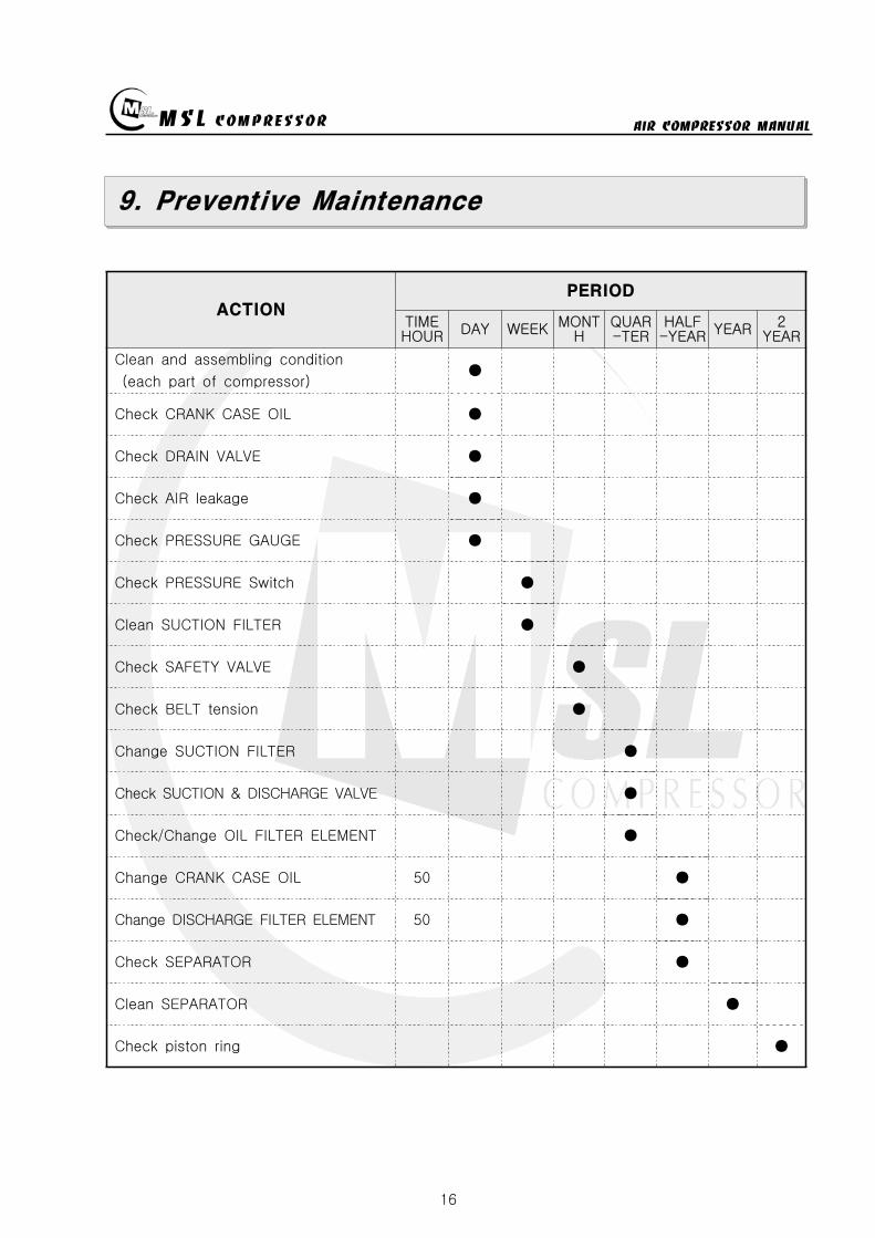
MSL COMPRESSOR AIR COMPRESSOR MANUAL
16
9 Preventive Maintenance
ACTIONPERIOD
TIMEHOUR DAY WEEK MONTH
QUAR-TER
HALF-YEAR YEAR
2YEAR
Clean and assembling condition
(each part of compressor)
Check CRANK CASE OIL
Check DRAIN VALVE
Check AIR leakage
Check PRESSURE GAUGE
Check PRESSURE Switch
Clean SUCTION FILTER
Check SAFETY VALVE
Check BELT tension
Change SUCTION FILTER
Check SUCTION amp DISCHARGE VALVE
CheckChange OIL FILTER ELEMENT
Change CRANK CASE OIL 50
Change DISCHARGE FILTER ELEMENT 50
Check SEPARATOR
Clean SEPARATOR
Check piston ring
MSL COMPRESSOR AIR COMPRESSOR MANUAL
P A R T L IS TMODEL MSF-300
MSL COMPRESSOR Co LtdHEAD OFFICE TEL 82 31 541 7000 FAX 82 31 542 2999HOME httpwwwmslcompcom
MSL COMPRESSOR AIR COMPRESSOR MANUAL
18
MSL COMPRESSOR AIR COMPRESSOR MANUAL
B HEAD ASSY
MSL COMPRESSOR AIR COMPRESSOR MANUAL
B HEAD ASSYKEY No PART No DESCRIPTION (Qty) NOTE
01 B-300-A-001 CRANK CASE
02 B-300-A-002 OIL GAUGE
03 B-300-F-001 SNAP RING
04 B-300-A-003 CRANK SHAFT
05 B-300-A-004 KEY
06 6306 BEARING
07 B-300-G-001 GASKET
08 B-300-A-005 BEARING COVER
09 B-300-A-006 OIL SEAL
10 6305ZZ BEARING
11 B-300-A-007 PULLEY
12 B-300-B-001 WASHER
13 B-300-B-002 BOLT
14 B-300-A-008 1 STAGE CONNECTION ROD
15 B-300-A-009 1 STAGE PISTON
16 B-300-A-010 1 STAGE PISTON PIN
17 B-300-F-002 SNAP RING
18 B-300-H-001 1 STAGE PISTON RING SET
19 B-300-G-002 GASKET
20 B-300-A-011 1 STAGE CYLINDER
21 B-300-B-003 SPRING WASHER
22 B-300-B-004 BOLT
23 B-300-G-003 GASKET
24 B-300-A-012 1 STAGE SUCTION amp DISCHARGE VALVE
25 B-300-B-005 BOLT
26 B-300-G-004 1 STAGE CYLINDER HEAD
26-1 B-300-G-004-1 BOLT
27 B-300-A-041 BOLT
28 B-300-A-042 GASKET
29 B-300-A-043 CAP NUT
MSL COMPRESSOR AIR COMPRESSOR MANUAL
B-B HEAD ASSYKEY No PART No DESCRIPTION (Qty) NOTE
30 B-300-A-014 2 STAGE CONNECTION ROD
30-1 B-300-A-014-1 3 STAGE CONNECTION ROD
31 B-300-A-015 23 STAGE PISTON PIN
32 B-300-A-016 2 STAGE PISTON
32-1 B-300-A-016-1 2 STAGE PISTON RING
33 B-300-G-005 GASKET
34 B-300-A-017 2 STAGE CYLINDER
35 B-300-G-005 GASKET
36 B-300-H-004 2 STAGE SD VALVE
37 B-300-A-018 2 STAGE CYLINDER HEAD
38 B-300-B-006 BOLT
39 B-300-A-019 3 STAGE PISTON
40 B-300-G-006 GASKET
41 B-300-A-020 3 STAGE CYLINDER
42 B-300-H-005 3 STAGE SD VALVE
43 B-300-A-021 3 STAGE CYLINDER HEAD
44 B-300-B-007 SPRING WASHER
45 B-300-B-008 BOLT
46 B-300-A-035 3 STAGE SPARE PISTON
47 B-300-A-036 2 STAGE SLEEVE
48 B-300-A-037 3 STAGE SLEEVE
49 HK3516 BEARING
50 HK1616B BEARING
51 B-300-A-038 2 STAGE VALVE BODY
52 B-300-A-039 3 STAGE VALVE BODY
53 B-300-A-040 SLEEVE HEAD GUARD
MSL COMPRESSOR AIR COMPRESSOR MANUAL
C 1 2 STAGE FILTER SETS
MSL COMPRESSOR AIR COMPRESSOR MANUAL
C 12 STAGE FILTER SETSKEY No PART No DESCRIPTION (Qty) NOTE
01 B-300-A-028 BODY
02 B-300-A-029 1 STAGE FILTER DOWN CAP
03 B-300-F-005 O-RING
04 B-300-A-030 1 STAGE FILTER ELEMENT
05 B-300-H-015 1 STAGE FILTER ELEMENT SET
06 B-300-H-016 1 STAGE FILTER DOWN CAP SET
07 B-300-F-006 O-RING
08 B-300-B-017 ALLEN SCREW
09 B-300-B-018 WASHER
10 B-300-B-019 SPRING WASHER
11 B-300-A-031 DRAIN VALVE
12 B-300-A-032 2 STAGE FILTER DOWN CAP
13 B-300-H-017 2 STAGE FILTER DOWN CAP SET
14 B-300-A-033 2 STAGE FILTER ELEMENT
15 B-300-H-018 2 STAGE FILTER ELEMENT SET
16 B-300-B-020 ALLEN SCREW
MSL COMPRESSOR AIR COMPRESSOR MANUAL
D AIR COOLING SYSTEM
MSL COMPRESSOR AIR COMPRESSOR MANUAL
D AIR COOLING SYSTEMKEY No PART No DESCRIPTION (Qty) NOTE
01 B-300-H-001 1 STAGE INTER COOLER SET 4
02 B-300-H-002 2 STAGE INTER COOLER SET 2
03 B-300-H-003 AFTER COOLER SET 2
04 B-300-H-004 AIR CONNECTING PIPE SET 4
05 B-300-H-005 CONNECTOR 7
06 B-300-H-006 CONNECTOR 2
07 B-300-H-007 CONNECTOR 2
08 B-300-B-008 SAFETY VALVE 1
09 B-300-B-009 CONNECTOR 1
MSL COMPRESSOR AIR COMPRESSOR MANUAL
E SEPARATOR SET
MSL COMPRESSOR AIR COMPRESSOR MANUAL
E SEPARATOR SETKEY No PART No DESCRIPTION (Qty) NOTE
01 B-300-A-023 BODY
02 B-300-A-024 SEPARATOR DOWN CAP
03 B-300-F-003 O-RING
04 B-300-H-013 SEPARATOR DOWN CAP SET
05 B-300-A-024 DRAIN VALVE
06 B-300-B-013 ALLEN SCREW
07 B-300-B-014 WASHER
08 B-300-B-015 SPRING WASHER
09 B-300-A-025 BOTTOM COVER
10 B-300-A-026 BEADS
11 B-300-A-027 TOP COVER
12 B-300-F-004 SPRING
13 B-300-H-014 ELEMENT SET
14 B-300-B-016 ALLEN SCREW
MSL COMPRESSOR AIR COMPRESSOR MANUAL
MSL COMPRESSOR AIR COMPRESSOR MANUAL
MSL COMPRESSOR AIR COMPRESSOR MANUAL
MSL COMPRESSOR AIR COMPRESSOR MANUAL
MEMO
MSL COMPRESSOR AIR COMPRESSOR MANUAL
P A R T L IS TMODEL MSF-300
MSL COMPRESSOR Co LtdHEAD OFFICE TEL 82 31 541 7000 FAX 82 31 542 2999HOME httpwwwmslcompcom
MSL COMPRESSOR AIR COMPRESSOR MANUAL
18
MSL COMPRESSOR AIR COMPRESSOR MANUAL
B HEAD ASSY
MSL COMPRESSOR AIR COMPRESSOR MANUAL
B HEAD ASSYKEY No PART No DESCRIPTION (Qty) NOTE
01 B-300-A-001 CRANK CASE
02 B-300-A-002 OIL GAUGE
03 B-300-F-001 SNAP RING
04 B-300-A-003 CRANK SHAFT
05 B-300-A-004 KEY
06 6306 BEARING
07 B-300-G-001 GASKET
08 B-300-A-005 BEARING COVER
09 B-300-A-006 OIL SEAL
10 6305ZZ BEARING
11 B-300-A-007 PULLEY
12 B-300-B-001 WASHER
13 B-300-B-002 BOLT
14 B-300-A-008 1 STAGE CONNECTION ROD
15 B-300-A-009 1 STAGE PISTON
16 B-300-A-010 1 STAGE PISTON PIN
17 B-300-F-002 SNAP RING
18 B-300-H-001 1 STAGE PISTON RING SET
19 B-300-G-002 GASKET
20 B-300-A-011 1 STAGE CYLINDER
21 B-300-B-003 SPRING WASHER
22 B-300-B-004 BOLT
23 B-300-G-003 GASKET
24 B-300-A-012 1 STAGE SUCTION amp DISCHARGE VALVE
25 B-300-B-005 BOLT
26 B-300-G-004 1 STAGE CYLINDER HEAD
26-1 B-300-G-004-1 BOLT
27 B-300-A-041 BOLT
28 B-300-A-042 GASKET
29 B-300-A-043 CAP NUT
MSL COMPRESSOR AIR COMPRESSOR MANUAL
B-B HEAD ASSYKEY No PART No DESCRIPTION (Qty) NOTE
30 B-300-A-014 2 STAGE CONNECTION ROD
30-1 B-300-A-014-1 3 STAGE CONNECTION ROD
31 B-300-A-015 23 STAGE PISTON PIN
32 B-300-A-016 2 STAGE PISTON
32-1 B-300-A-016-1 2 STAGE PISTON RING
33 B-300-G-005 GASKET
34 B-300-A-017 2 STAGE CYLINDER
35 B-300-G-005 GASKET
36 B-300-H-004 2 STAGE SD VALVE
37 B-300-A-018 2 STAGE CYLINDER HEAD
38 B-300-B-006 BOLT
39 B-300-A-019 3 STAGE PISTON
40 B-300-G-006 GASKET
41 B-300-A-020 3 STAGE CYLINDER
42 B-300-H-005 3 STAGE SD VALVE
43 B-300-A-021 3 STAGE CYLINDER HEAD
44 B-300-B-007 SPRING WASHER
45 B-300-B-008 BOLT
46 B-300-A-035 3 STAGE SPARE PISTON
47 B-300-A-036 2 STAGE SLEEVE
48 B-300-A-037 3 STAGE SLEEVE
49 HK3516 BEARING
50 HK1616B BEARING
51 B-300-A-038 2 STAGE VALVE BODY
52 B-300-A-039 3 STAGE VALVE BODY
53 B-300-A-040 SLEEVE HEAD GUARD
MSL COMPRESSOR AIR COMPRESSOR MANUAL
C 1 2 STAGE FILTER SETS
MSL COMPRESSOR AIR COMPRESSOR MANUAL
C 12 STAGE FILTER SETSKEY No PART No DESCRIPTION (Qty) NOTE
01 B-300-A-028 BODY
02 B-300-A-029 1 STAGE FILTER DOWN CAP
03 B-300-F-005 O-RING
04 B-300-A-030 1 STAGE FILTER ELEMENT
05 B-300-H-015 1 STAGE FILTER ELEMENT SET
06 B-300-H-016 1 STAGE FILTER DOWN CAP SET
07 B-300-F-006 O-RING
08 B-300-B-017 ALLEN SCREW
09 B-300-B-018 WASHER
10 B-300-B-019 SPRING WASHER
11 B-300-A-031 DRAIN VALVE
12 B-300-A-032 2 STAGE FILTER DOWN CAP
13 B-300-H-017 2 STAGE FILTER DOWN CAP SET
14 B-300-A-033 2 STAGE FILTER ELEMENT
15 B-300-H-018 2 STAGE FILTER ELEMENT SET
16 B-300-B-020 ALLEN SCREW
MSL COMPRESSOR AIR COMPRESSOR MANUAL
D AIR COOLING SYSTEM
MSL COMPRESSOR AIR COMPRESSOR MANUAL
D AIR COOLING SYSTEMKEY No PART No DESCRIPTION (Qty) NOTE
01 B-300-H-001 1 STAGE INTER COOLER SET 4
02 B-300-H-002 2 STAGE INTER COOLER SET 2
03 B-300-H-003 AFTER COOLER SET 2
04 B-300-H-004 AIR CONNECTING PIPE SET 4
05 B-300-H-005 CONNECTOR 7
06 B-300-H-006 CONNECTOR 2
07 B-300-H-007 CONNECTOR 2
08 B-300-B-008 SAFETY VALVE 1
09 B-300-B-009 CONNECTOR 1
MSL COMPRESSOR AIR COMPRESSOR MANUAL
E SEPARATOR SET
MSL COMPRESSOR AIR COMPRESSOR MANUAL
E SEPARATOR SETKEY No PART No DESCRIPTION (Qty) NOTE
01 B-300-A-023 BODY
02 B-300-A-024 SEPARATOR DOWN CAP
03 B-300-F-003 O-RING
04 B-300-H-013 SEPARATOR DOWN CAP SET
05 B-300-A-024 DRAIN VALVE
06 B-300-B-013 ALLEN SCREW
07 B-300-B-014 WASHER
08 B-300-B-015 SPRING WASHER
09 B-300-A-025 BOTTOM COVER
10 B-300-A-026 BEADS
11 B-300-A-027 TOP COVER
12 B-300-F-004 SPRING
13 B-300-H-014 ELEMENT SET
14 B-300-B-016 ALLEN SCREW
MSL COMPRESSOR AIR COMPRESSOR MANUAL
MSL COMPRESSOR AIR COMPRESSOR MANUAL
MSL COMPRESSOR AIR COMPRESSOR MANUAL
MSL COMPRESSOR AIR COMPRESSOR MANUAL
MEMO
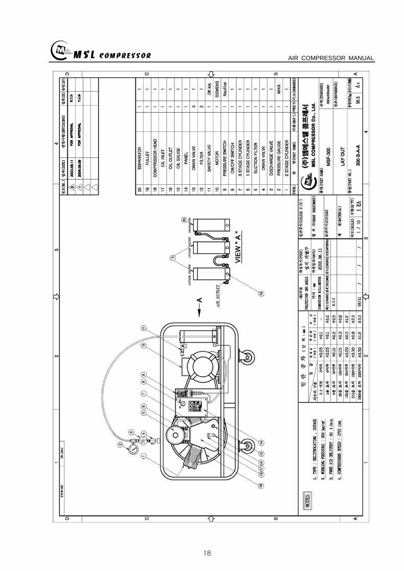
MSL COMPRESSOR AIR COMPRESSOR MANUAL
18
MSL COMPRESSOR AIR COMPRESSOR MANUAL
B HEAD ASSY
MSL COMPRESSOR AIR COMPRESSOR MANUAL
B HEAD ASSYKEY No PART No DESCRIPTION (Qty) NOTE
01 B-300-A-001 CRANK CASE
02 B-300-A-002 OIL GAUGE
03 B-300-F-001 SNAP RING
04 B-300-A-003 CRANK SHAFT
05 B-300-A-004 KEY
06 6306 BEARING
07 B-300-G-001 GASKET
08 B-300-A-005 BEARING COVER
09 B-300-A-006 OIL SEAL
10 6305ZZ BEARING
11 B-300-A-007 PULLEY
12 B-300-B-001 WASHER
13 B-300-B-002 BOLT
14 B-300-A-008 1 STAGE CONNECTION ROD
15 B-300-A-009 1 STAGE PISTON
16 B-300-A-010 1 STAGE PISTON PIN
17 B-300-F-002 SNAP RING
18 B-300-H-001 1 STAGE PISTON RING SET
19 B-300-G-002 GASKET
20 B-300-A-011 1 STAGE CYLINDER
21 B-300-B-003 SPRING WASHER
22 B-300-B-004 BOLT
23 B-300-G-003 GASKET
24 B-300-A-012 1 STAGE SUCTION amp DISCHARGE VALVE
25 B-300-B-005 BOLT
26 B-300-G-004 1 STAGE CYLINDER HEAD
26-1 B-300-G-004-1 BOLT
27 B-300-A-041 BOLT
28 B-300-A-042 GASKET
29 B-300-A-043 CAP NUT
MSL COMPRESSOR AIR COMPRESSOR MANUAL
B-B HEAD ASSYKEY No PART No DESCRIPTION (Qty) NOTE
30 B-300-A-014 2 STAGE CONNECTION ROD
30-1 B-300-A-014-1 3 STAGE CONNECTION ROD
31 B-300-A-015 23 STAGE PISTON PIN
32 B-300-A-016 2 STAGE PISTON
32-1 B-300-A-016-1 2 STAGE PISTON RING
33 B-300-G-005 GASKET
34 B-300-A-017 2 STAGE CYLINDER
35 B-300-G-005 GASKET
36 B-300-H-004 2 STAGE SD VALVE
37 B-300-A-018 2 STAGE CYLINDER HEAD
38 B-300-B-006 BOLT
39 B-300-A-019 3 STAGE PISTON
40 B-300-G-006 GASKET
41 B-300-A-020 3 STAGE CYLINDER
42 B-300-H-005 3 STAGE SD VALVE
43 B-300-A-021 3 STAGE CYLINDER HEAD
44 B-300-B-007 SPRING WASHER
45 B-300-B-008 BOLT
46 B-300-A-035 3 STAGE SPARE PISTON
47 B-300-A-036 2 STAGE SLEEVE
48 B-300-A-037 3 STAGE SLEEVE
49 HK3516 BEARING
50 HK1616B BEARING
51 B-300-A-038 2 STAGE VALVE BODY
52 B-300-A-039 3 STAGE VALVE BODY
53 B-300-A-040 SLEEVE HEAD GUARD
MSL COMPRESSOR AIR COMPRESSOR MANUAL
C 1 2 STAGE FILTER SETS
MSL COMPRESSOR AIR COMPRESSOR MANUAL
C 12 STAGE FILTER SETSKEY No PART No DESCRIPTION (Qty) NOTE
01 B-300-A-028 BODY
02 B-300-A-029 1 STAGE FILTER DOWN CAP
03 B-300-F-005 O-RING
04 B-300-A-030 1 STAGE FILTER ELEMENT
05 B-300-H-015 1 STAGE FILTER ELEMENT SET
06 B-300-H-016 1 STAGE FILTER DOWN CAP SET
07 B-300-F-006 O-RING
08 B-300-B-017 ALLEN SCREW
09 B-300-B-018 WASHER
10 B-300-B-019 SPRING WASHER
11 B-300-A-031 DRAIN VALVE
12 B-300-A-032 2 STAGE FILTER DOWN CAP
13 B-300-H-017 2 STAGE FILTER DOWN CAP SET
14 B-300-A-033 2 STAGE FILTER ELEMENT
15 B-300-H-018 2 STAGE FILTER ELEMENT SET
16 B-300-B-020 ALLEN SCREW
MSL COMPRESSOR AIR COMPRESSOR MANUAL
D AIR COOLING SYSTEM
MSL COMPRESSOR AIR COMPRESSOR MANUAL
D AIR COOLING SYSTEMKEY No PART No DESCRIPTION (Qty) NOTE
01 B-300-H-001 1 STAGE INTER COOLER SET 4
02 B-300-H-002 2 STAGE INTER COOLER SET 2
03 B-300-H-003 AFTER COOLER SET 2
04 B-300-H-004 AIR CONNECTING PIPE SET 4
05 B-300-H-005 CONNECTOR 7
06 B-300-H-006 CONNECTOR 2
07 B-300-H-007 CONNECTOR 2
08 B-300-B-008 SAFETY VALVE 1
09 B-300-B-009 CONNECTOR 1
MSL COMPRESSOR AIR COMPRESSOR MANUAL
E SEPARATOR SET
MSL COMPRESSOR AIR COMPRESSOR MANUAL
E SEPARATOR SETKEY No PART No DESCRIPTION (Qty) NOTE
01 B-300-A-023 BODY
02 B-300-A-024 SEPARATOR DOWN CAP
03 B-300-F-003 O-RING
04 B-300-H-013 SEPARATOR DOWN CAP SET
05 B-300-A-024 DRAIN VALVE
06 B-300-B-013 ALLEN SCREW
07 B-300-B-014 WASHER
08 B-300-B-015 SPRING WASHER
09 B-300-A-025 BOTTOM COVER
10 B-300-A-026 BEADS
11 B-300-A-027 TOP COVER
12 B-300-F-004 SPRING
13 B-300-H-014 ELEMENT SET
14 B-300-B-016 ALLEN SCREW
MSL COMPRESSOR AIR COMPRESSOR MANUAL
MSL COMPRESSOR AIR COMPRESSOR MANUAL
MSL COMPRESSOR AIR COMPRESSOR MANUAL
MSL COMPRESSOR AIR COMPRESSOR MANUAL
MEMO
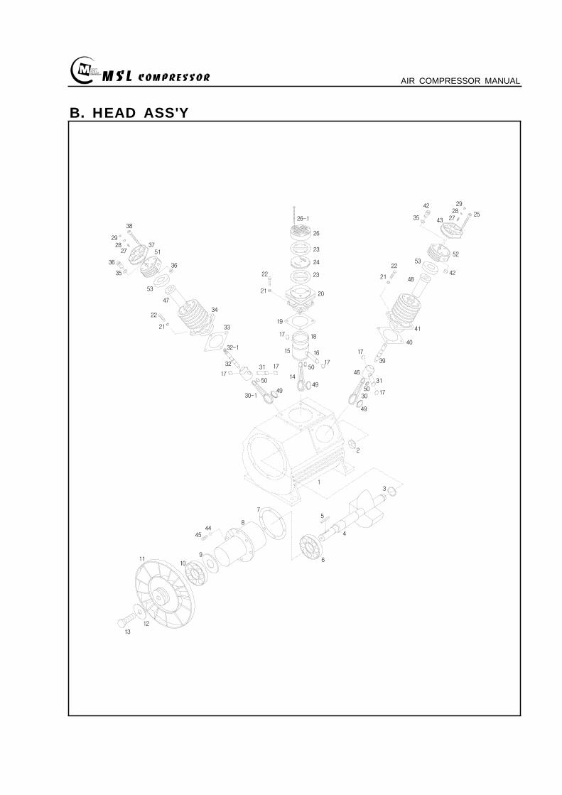
MSL COMPRESSOR AIR COMPRESSOR MANUAL
B HEAD ASSY
MSL COMPRESSOR AIR COMPRESSOR MANUAL
B HEAD ASSYKEY No PART No DESCRIPTION (Qty) NOTE
01 B-300-A-001 CRANK CASE
02 B-300-A-002 OIL GAUGE
03 B-300-F-001 SNAP RING
04 B-300-A-003 CRANK SHAFT
05 B-300-A-004 KEY
06 6306 BEARING
07 B-300-G-001 GASKET
08 B-300-A-005 BEARING COVER
09 B-300-A-006 OIL SEAL
10 6305ZZ BEARING
11 B-300-A-007 PULLEY
12 B-300-B-001 WASHER
13 B-300-B-002 BOLT
14 B-300-A-008 1 STAGE CONNECTION ROD
15 B-300-A-009 1 STAGE PISTON
16 B-300-A-010 1 STAGE PISTON PIN
17 B-300-F-002 SNAP RING
18 B-300-H-001 1 STAGE PISTON RING SET
19 B-300-G-002 GASKET
20 B-300-A-011 1 STAGE CYLINDER
21 B-300-B-003 SPRING WASHER
22 B-300-B-004 BOLT
23 B-300-G-003 GASKET
24 B-300-A-012 1 STAGE SUCTION amp DISCHARGE VALVE
25 B-300-B-005 BOLT
26 B-300-G-004 1 STAGE CYLINDER HEAD
26-1 B-300-G-004-1 BOLT
27 B-300-A-041 BOLT
28 B-300-A-042 GASKET
29 B-300-A-043 CAP NUT
MSL COMPRESSOR AIR COMPRESSOR MANUAL
B-B HEAD ASSYKEY No PART No DESCRIPTION (Qty) NOTE
30 B-300-A-014 2 STAGE CONNECTION ROD
30-1 B-300-A-014-1 3 STAGE CONNECTION ROD
31 B-300-A-015 23 STAGE PISTON PIN
32 B-300-A-016 2 STAGE PISTON
32-1 B-300-A-016-1 2 STAGE PISTON RING
33 B-300-G-005 GASKET
34 B-300-A-017 2 STAGE CYLINDER
35 B-300-G-005 GASKET
36 B-300-H-004 2 STAGE SD VALVE
37 B-300-A-018 2 STAGE CYLINDER HEAD
38 B-300-B-006 BOLT
39 B-300-A-019 3 STAGE PISTON
40 B-300-G-006 GASKET
41 B-300-A-020 3 STAGE CYLINDER
42 B-300-H-005 3 STAGE SD VALVE
43 B-300-A-021 3 STAGE CYLINDER HEAD
44 B-300-B-007 SPRING WASHER
45 B-300-B-008 BOLT
46 B-300-A-035 3 STAGE SPARE PISTON
47 B-300-A-036 2 STAGE SLEEVE
48 B-300-A-037 3 STAGE SLEEVE
49 HK3516 BEARING
50 HK1616B BEARING
51 B-300-A-038 2 STAGE VALVE BODY
52 B-300-A-039 3 STAGE VALVE BODY
53 B-300-A-040 SLEEVE HEAD GUARD
MSL COMPRESSOR AIR COMPRESSOR MANUAL
C 1 2 STAGE FILTER SETS
MSL COMPRESSOR AIR COMPRESSOR MANUAL
C 12 STAGE FILTER SETSKEY No PART No DESCRIPTION (Qty) NOTE
01 B-300-A-028 BODY
02 B-300-A-029 1 STAGE FILTER DOWN CAP
03 B-300-F-005 O-RING
04 B-300-A-030 1 STAGE FILTER ELEMENT
05 B-300-H-015 1 STAGE FILTER ELEMENT SET
06 B-300-H-016 1 STAGE FILTER DOWN CAP SET
07 B-300-F-006 O-RING
08 B-300-B-017 ALLEN SCREW
09 B-300-B-018 WASHER
10 B-300-B-019 SPRING WASHER
11 B-300-A-031 DRAIN VALVE
12 B-300-A-032 2 STAGE FILTER DOWN CAP
13 B-300-H-017 2 STAGE FILTER DOWN CAP SET
14 B-300-A-033 2 STAGE FILTER ELEMENT
15 B-300-H-018 2 STAGE FILTER ELEMENT SET
16 B-300-B-020 ALLEN SCREW
MSL COMPRESSOR AIR COMPRESSOR MANUAL
D AIR COOLING SYSTEM
MSL COMPRESSOR AIR COMPRESSOR MANUAL
D AIR COOLING SYSTEMKEY No PART No DESCRIPTION (Qty) NOTE
01 B-300-H-001 1 STAGE INTER COOLER SET 4
02 B-300-H-002 2 STAGE INTER COOLER SET 2
03 B-300-H-003 AFTER COOLER SET 2
04 B-300-H-004 AIR CONNECTING PIPE SET 4
05 B-300-H-005 CONNECTOR 7
06 B-300-H-006 CONNECTOR 2
07 B-300-H-007 CONNECTOR 2
08 B-300-B-008 SAFETY VALVE 1
09 B-300-B-009 CONNECTOR 1
MSL COMPRESSOR AIR COMPRESSOR MANUAL
E SEPARATOR SET
MSL COMPRESSOR AIR COMPRESSOR MANUAL
E SEPARATOR SETKEY No PART No DESCRIPTION (Qty) NOTE
01 B-300-A-023 BODY
02 B-300-A-024 SEPARATOR DOWN CAP
03 B-300-F-003 O-RING
04 B-300-H-013 SEPARATOR DOWN CAP SET
05 B-300-A-024 DRAIN VALVE
06 B-300-B-013 ALLEN SCREW
07 B-300-B-014 WASHER
08 B-300-B-015 SPRING WASHER
09 B-300-A-025 BOTTOM COVER
10 B-300-A-026 BEADS
11 B-300-A-027 TOP COVER
12 B-300-F-004 SPRING
13 B-300-H-014 ELEMENT SET
14 B-300-B-016 ALLEN SCREW
MSL COMPRESSOR AIR COMPRESSOR MANUAL
MSL COMPRESSOR AIR COMPRESSOR MANUAL
MSL COMPRESSOR AIR COMPRESSOR MANUAL
MSL COMPRESSOR AIR COMPRESSOR MANUAL
MEMO
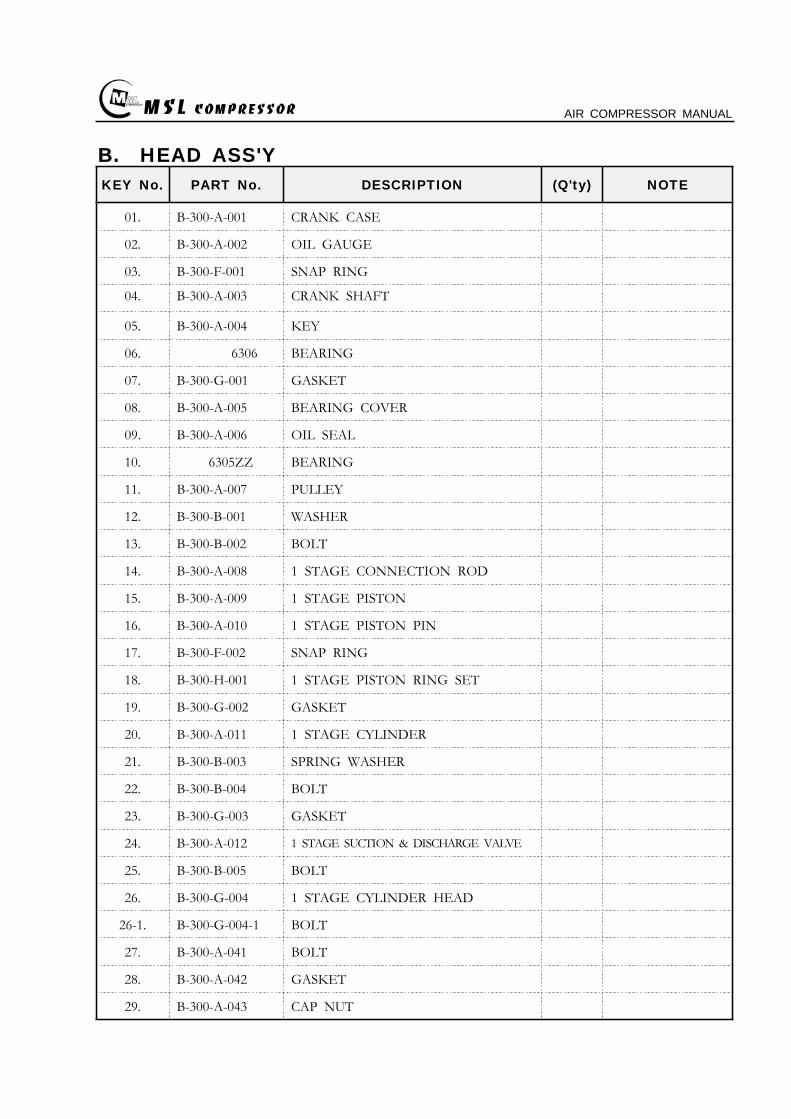
MSL COMPRESSOR AIR COMPRESSOR MANUAL
B HEAD ASSYKEY No PART No DESCRIPTION (Qty) NOTE
01 B-300-A-001 CRANK CASE
02 B-300-A-002 OIL GAUGE
03 B-300-F-001 SNAP RING
04 B-300-A-003 CRANK SHAFT
05 B-300-A-004 KEY
06 6306 BEARING
07 B-300-G-001 GASKET
08 B-300-A-005 BEARING COVER
09 B-300-A-006 OIL SEAL
10 6305ZZ BEARING
11 B-300-A-007 PULLEY
12 B-300-B-001 WASHER
13 B-300-B-002 BOLT
14 B-300-A-008 1 STAGE CONNECTION ROD
15 B-300-A-009 1 STAGE PISTON
16 B-300-A-010 1 STAGE PISTON PIN
17 B-300-F-002 SNAP RING
18 B-300-H-001 1 STAGE PISTON RING SET
19 B-300-G-002 GASKET
20 B-300-A-011 1 STAGE CYLINDER
21 B-300-B-003 SPRING WASHER
22 B-300-B-004 BOLT
23 B-300-G-003 GASKET
24 B-300-A-012 1 STAGE SUCTION amp DISCHARGE VALVE
25 B-300-B-005 BOLT
26 B-300-G-004 1 STAGE CYLINDER HEAD
26-1 B-300-G-004-1 BOLT
27 B-300-A-041 BOLT
28 B-300-A-042 GASKET
29 B-300-A-043 CAP NUT
MSL COMPRESSOR AIR COMPRESSOR MANUAL
B-B HEAD ASSYKEY No PART No DESCRIPTION (Qty) NOTE
30 B-300-A-014 2 STAGE CONNECTION ROD
30-1 B-300-A-014-1 3 STAGE CONNECTION ROD
31 B-300-A-015 23 STAGE PISTON PIN
32 B-300-A-016 2 STAGE PISTON
32-1 B-300-A-016-1 2 STAGE PISTON RING
33 B-300-G-005 GASKET
34 B-300-A-017 2 STAGE CYLINDER
35 B-300-G-005 GASKET
36 B-300-H-004 2 STAGE SD VALVE
37 B-300-A-018 2 STAGE CYLINDER HEAD
38 B-300-B-006 BOLT
39 B-300-A-019 3 STAGE PISTON
40 B-300-G-006 GASKET
41 B-300-A-020 3 STAGE CYLINDER
42 B-300-H-005 3 STAGE SD VALVE
43 B-300-A-021 3 STAGE CYLINDER HEAD
44 B-300-B-007 SPRING WASHER
45 B-300-B-008 BOLT
46 B-300-A-035 3 STAGE SPARE PISTON
47 B-300-A-036 2 STAGE SLEEVE
48 B-300-A-037 3 STAGE SLEEVE
49 HK3516 BEARING
50 HK1616B BEARING
51 B-300-A-038 2 STAGE VALVE BODY
52 B-300-A-039 3 STAGE VALVE BODY
53 B-300-A-040 SLEEVE HEAD GUARD
MSL COMPRESSOR AIR COMPRESSOR MANUAL
C 1 2 STAGE FILTER SETS
MSL COMPRESSOR AIR COMPRESSOR MANUAL
C 12 STAGE FILTER SETSKEY No PART No DESCRIPTION (Qty) NOTE
01 B-300-A-028 BODY
02 B-300-A-029 1 STAGE FILTER DOWN CAP
03 B-300-F-005 O-RING
04 B-300-A-030 1 STAGE FILTER ELEMENT
05 B-300-H-015 1 STAGE FILTER ELEMENT SET
06 B-300-H-016 1 STAGE FILTER DOWN CAP SET
07 B-300-F-006 O-RING
08 B-300-B-017 ALLEN SCREW
09 B-300-B-018 WASHER
10 B-300-B-019 SPRING WASHER
11 B-300-A-031 DRAIN VALVE
12 B-300-A-032 2 STAGE FILTER DOWN CAP
13 B-300-H-017 2 STAGE FILTER DOWN CAP SET
14 B-300-A-033 2 STAGE FILTER ELEMENT
15 B-300-H-018 2 STAGE FILTER ELEMENT SET
16 B-300-B-020 ALLEN SCREW
MSL COMPRESSOR AIR COMPRESSOR MANUAL
D AIR COOLING SYSTEM
MSL COMPRESSOR AIR COMPRESSOR MANUAL
D AIR COOLING SYSTEMKEY No PART No DESCRIPTION (Qty) NOTE
01 B-300-H-001 1 STAGE INTER COOLER SET 4
02 B-300-H-002 2 STAGE INTER COOLER SET 2
03 B-300-H-003 AFTER COOLER SET 2
04 B-300-H-004 AIR CONNECTING PIPE SET 4
05 B-300-H-005 CONNECTOR 7
06 B-300-H-006 CONNECTOR 2
07 B-300-H-007 CONNECTOR 2
08 B-300-B-008 SAFETY VALVE 1
09 B-300-B-009 CONNECTOR 1
MSL COMPRESSOR AIR COMPRESSOR MANUAL
E SEPARATOR SET
MSL COMPRESSOR AIR COMPRESSOR MANUAL
E SEPARATOR SETKEY No PART No DESCRIPTION (Qty) NOTE
01 B-300-A-023 BODY
02 B-300-A-024 SEPARATOR DOWN CAP
03 B-300-F-003 O-RING
04 B-300-H-013 SEPARATOR DOWN CAP SET
05 B-300-A-024 DRAIN VALVE
06 B-300-B-013 ALLEN SCREW
07 B-300-B-014 WASHER
08 B-300-B-015 SPRING WASHER
09 B-300-A-025 BOTTOM COVER
10 B-300-A-026 BEADS
11 B-300-A-027 TOP COVER
12 B-300-F-004 SPRING
13 B-300-H-014 ELEMENT SET
14 B-300-B-016 ALLEN SCREW
MSL COMPRESSOR AIR COMPRESSOR MANUAL
MSL COMPRESSOR AIR COMPRESSOR MANUAL
MSL COMPRESSOR AIR COMPRESSOR MANUAL
MSL COMPRESSOR AIR COMPRESSOR MANUAL
MEMO
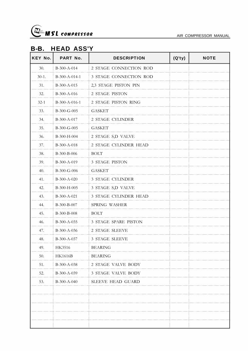
MSL COMPRESSOR AIR COMPRESSOR MANUAL
B-B HEAD ASSYKEY No PART No DESCRIPTION (Qty) NOTE
30 B-300-A-014 2 STAGE CONNECTION ROD
30-1 B-300-A-014-1 3 STAGE CONNECTION ROD
31 B-300-A-015 23 STAGE PISTON PIN
32 B-300-A-016 2 STAGE PISTON
32-1 B-300-A-016-1 2 STAGE PISTON RING
33 B-300-G-005 GASKET
34 B-300-A-017 2 STAGE CYLINDER
35 B-300-G-005 GASKET
36 B-300-H-004 2 STAGE SD VALVE
37 B-300-A-018 2 STAGE CYLINDER HEAD
38 B-300-B-006 BOLT
39 B-300-A-019 3 STAGE PISTON
40 B-300-G-006 GASKET
41 B-300-A-020 3 STAGE CYLINDER
42 B-300-H-005 3 STAGE SD VALVE
43 B-300-A-021 3 STAGE CYLINDER HEAD
44 B-300-B-007 SPRING WASHER
45 B-300-B-008 BOLT
46 B-300-A-035 3 STAGE SPARE PISTON
47 B-300-A-036 2 STAGE SLEEVE
48 B-300-A-037 3 STAGE SLEEVE
49 HK3516 BEARING
50 HK1616B BEARING
51 B-300-A-038 2 STAGE VALVE BODY
52 B-300-A-039 3 STAGE VALVE BODY
53 B-300-A-040 SLEEVE HEAD GUARD
MSL COMPRESSOR AIR COMPRESSOR MANUAL
C 1 2 STAGE FILTER SETS
MSL COMPRESSOR AIR COMPRESSOR MANUAL
C 12 STAGE FILTER SETSKEY No PART No DESCRIPTION (Qty) NOTE
01 B-300-A-028 BODY
02 B-300-A-029 1 STAGE FILTER DOWN CAP
03 B-300-F-005 O-RING
04 B-300-A-030 1 STAGE FILTER ELEMENT
05 B-300-H-015 1 STAGE FILTER ELEMENT SET
06 B-300-H-016 1 STAGE FILTER DOWN CAP SET
07 B-300-F-006 O-RING
08 B-300-B-017 ALLEN SCREW
09 B-300-B-018 WASHER
10 B-300-B-019 SPRING WASHER
11 B-300-A-031 DRAIN VALVE
12 B-300-A-032 2 STAGE FILTER DOWN CAP
13 B-300-H-017 2 STAGE FILTER DOWN CAP SET
14 B-300-A-033 2 STAGE FILTER ELEMENT
15 B-300-H-018 2 STAGE FILTER ELEMENT SET
16 B-300-B-020 ALLEN SCREW
MSL COMPRESSOR AIR COMPRESSOR MANUAL
D AIR COOLING SYSTEM
MSL COMPRESSOR AIR COMPRESSOR MANUAL
D AIR COOLING SYSTEMKEY No PART No DESCRIPTION (Qty) NOTE
01 B-300-H-001 1 STAGE INTER COOLER SET 4
02 B-300-H-002 2 STAGE INTER COOLER SET 2
03 B-300-H-003 AFTER COOLER SET 2
04 B-300-H-004 AIR CONNECTING PIPE SET 4
05 B-300-H-005 CONNECTOR 7
06 B-300-H-006 CONNECTOR 2
07 B-300-H-007 CONNECTOR 2
08 B-300-B-008 SAFETY VALVE 1
09 B-300-B-009 CONNECTOR 1
MSL COMPRESSOR AIR COMPRESSOR MANUAL
E SEPARATOR SET
MSL COMPRESSOR AIR COMPRESSOR MANUAL
E SEPARATOR SETKEY No PART No DESCRIPTION (Qty) NOTE
01 B-300-A-023 BODY
02 B-300-A-024 SEPARATOR DOWN CAP
03 B-300-F-003 O-RING
04 B-300-H-013 SEPARATOR DOWN CAP SET
05 B-300-A-024 DRAIN VALVE
06 B-300-B-013 ALLEN SCREW
07 B-300-B-014 WASHER
08 B-300-B-015 SPRING WASHER
09 B-300-A-025 BOTTOM COVER
10 B-300-A-026 BEADS
11 B-300-A-027 TOP COVER
12 B-300-F-004 SPRING
13 B-300-H-014 ELEMENT SET
14 B-300-B-016 ALLEN SCREW
MSL COMPRESSOR AIR COMPRESSOR MANUAL
MSL COMPRESSOR AIR COMPRESSOR MANUAL
MSL COMPRESSOR AIR COMPRESSOR MANUAL
MSL COMPRESSOR AIR COMPRESSOR MANUAL
MEMO
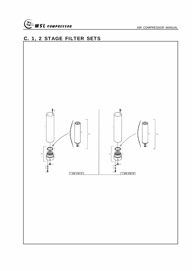
MSL COMPRESSOR AIR COMPRESSOR MANUAL
C 1 2 STAGE FILTER SETS
MSL COMPRESSOR AIR COMPRESSOR MANUAL
C 12 STAGE FILTER SETSKEY No PART No DESCRIPTION (Qty) NOTE
01 B-300-A-028 BODY
02 B-300-A-029 1 STAGE FILTER DOWN CAP
03 B-300-F-005 O-RING
04 B-300-A-030 1 STAGE FILTER ELEMENT
05 B-300-H-015 1 STAGE FILTER ELEMENT SET
06 B-300-H-016 1 STAGE FILTER DOWN CAP SET
07 B-300-F-006 O-RING
08 B-300-B-017 ALLEN SCREW
09 B-300-B-018 WASHER
10 B-300-B-019 SPRING WASHER
11 B-300-A-031 DRAIN VALVE
12 B-300-A-032 2 STAGE FILTER DOWN CAP
13 B-300-H-017 2 STAGE FILTER DOWN CAP SET
14 B-300-A-033 2 STAGE FILTER ELEMENT
15 B-300-H-018 2 STAGE FILTER ELEMENT SET
16 B-300-B-020 ALLEN SCREW
MSL COMPRESSOR AIR COMPRESSOR MANUAL
D AIR COOLING SYSTEM
MSL COMPRESSOR AIR COMPRESSOR MANUAL
D AIR COOLING SYSTEMKEY No PART No DESCRIPTION (Qty) NOTE
01 B-300-H-001 1 STAGE INTER COOLER SET 4
02 B-300-H-002 2 STAGE INTER COOLER SET 2
03 B-300-H-003 AFTER COOLER SET 2
04 B-300-H-004 AIR CONNECTING PIPE SET 4
05 B-300-H-005 CONNECTOR 7
06 B-300-H-006 CONNECTOR 2
07 B-300-H-007 CONNECTOR 2
08 B-300-B-008 SAFETY VALVE 1
09 B-300-B-009 CONNECTOR 1
MSL COMPRESSOR AIR COMPRESSOR MANUAL
E SEPARATOR SET
MSL COMPRESSOR AIR COMPRESSOR MANUAL
E SEPARATOR SETKEY No PART No DESCRIPTION (Qty) NOTE
01 B-300-A-023 BODY
02 B-300-A-024 SEPARATOR DOWN CAP
03 B-300-F-003 O-RING
04 B-300-H-013 SEPARATOR DOWN CAP SET
05 B-300-A-024 DRAIN VALVE
06 B-300-B-013 ALLEN SCREW
07 B-300-B-014 WASHER
08 B-300-B-015 SPRING WASHER
09 B-300-A-025 BOTTOM COVER
10 B-300-A-026 BEADS
11 B-300-A-027 TOP COVER
12 B-300-F-004 SPRING
13 B-300-H-014 ELEMENT SET
14 B-300-B-016 ALLEN SCREW
MSL COMPRESSOR AIR COMPRESSOR MANUAL
MSL COMPRESSOR AIR COMPRESSOR MANUAL
MSL COMPRESSOR AIR COMPRESSOR MANUAL
MSL COMPRESSOR AIR COMPRESSOR MANUAL
MEMO
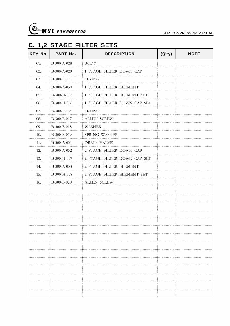
MSL COMPRESSOR AIR COMPRESSOR MANUAL
C 12 STAGE FILTER SETSKEY No PART No DESCRIPTION (Qty) NOTE
01 B-300-A-028 BODY
02 B-300-A-029 1 STAGE FILTER DOWN CAP
03 B-300-F-005 O-RING
04 B-300-A-030 1 STAGE FILTER ELEMENT
05 B-300-H-015 1 STAGE FILTER ELEMENT SET
06 B-300-H-016 1 STAGE FILTER DOWN CAP SET
07 B-300-F-006 O-RING
08 B-300-B-017 ALLEN SCREW
09 B-300-B-018 WASHER
10 B-300-B-019 SPRING WASHER
11 B-300-A-031 DRAIN VALVE
12 B-300-A-032 2 STAGE FILTER DOWN CAP
13 B-300-H-017 2 STAGE FILTER DOWN CAP SET
14 B-300-A-033 2 STAGE FILTER ELEMENT
15 B-300-H-018 2 STAGE FILTER ELEMENT SET
16 B-300-B-020 ALLEN SCREW
MSL COMPRESSOR AIR COMPRESSOR MANUAL
D AIR COOLING SYSTEM
MSL COMPRESSOR AIR COMPRESSOR MANUAL
D AIR COOLING SYSTEMKEY No PART No DESCRIPTION (Qty) NOTE
01 B-300-H-001 1 STAGE INTER COOLER SET 4
02 B-300-H-002 2 STAGE INTER COOLER SET 2
03 B-300-H-003 AFTER COOLER SET 2
04 B-300-H-004 AIR CONNECTING PIPE SET 4
05 B-300-H-005 CONNECTOR 7
06 B-300-H-006 CONNECTOR 2
07 B-300-H-007 CONNECTOR 2
08 B-300-B-008 SAFETY VALVE 1
09 B-300-B-009 CONNECTOR 1
MSL COMPRESSOR AIR COMPRESSOR MANUAL
E SEPARATOR SET
MSL COMPRESSOR AIR COMPRESSOR MANUAL
E SEPARATOR SETKEY No PART No DESCRIPTION (Qty) NOTE
01 B-300-A-023 BODY
02 B-300-A-024 SEPARATOR DOWN CAP
03 B-300-F-003 O-RING
04 B-300-H-013 SEPARATOR DOWN CAP SET
05 B-300-A-024 DRAIN VALVE
06 B-300-B-013 ALLEN SCREW
07 B-300-B-014 WASHER
08 B-300-B-015 SPRING WASHER
09 B-300-A-025 BOTTOM COVER
10 B-300-A-026 BEADS
11 B-300-A-027 TOP COVER
12 B-300-F-004 SPRING
13 B-300-H-014 ELEMENT SET
14 B-300-B-016 ALLEN SCREW
MSL COMPRESSOR AIR COMPRESSOR MANUAL
MSL COMPRESSOR AIR COMPRESSOR MANUAL
MSL COMPRESSOR AIR COMPRESSOR MANUAL
MSL COMPRESSOR AIR COMPRESSOR MANUAL
MEMO
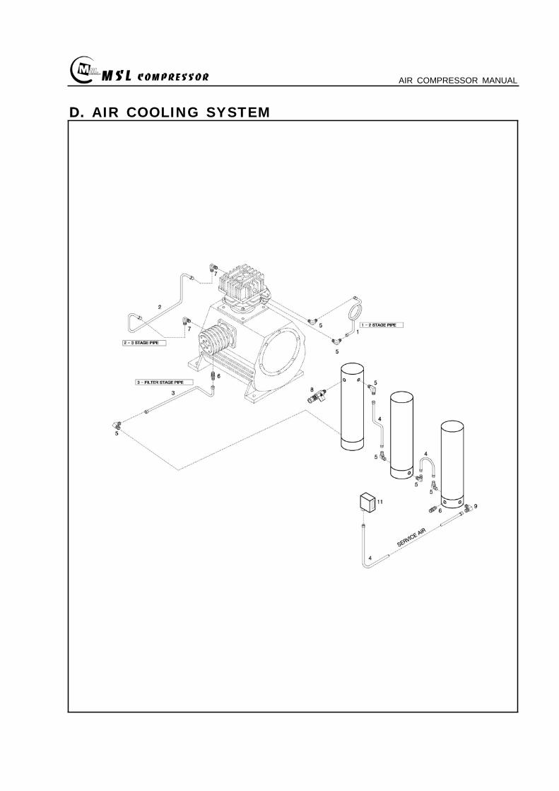
MSL COMPRESSOR AIR COMPRESSOR MANUAL
D AIR COOLING SYSTEM
MSL COMPRESSOR AIR COMPRESSOR MANUAL
D AIR COOLING SYSTEMKEY No PART No DESCRIPTION (Qty) NOTE
01 B-300-H-001 1 STAGE INTER COOLER SET 4
02 B-300-H-002 2 STAGE INTER COOLER SET 2
03 B-300-H-003 AFTER COOLER SET 2
04 B-300-H-004 AIR CONNECTING PIPE SET 4
05 B-300-H-005 CONNECTOR 7
06 B-300-H-006 CONNECTOR 2
07 B-300-H-007 CONNECTOR 2
08 B-300-B-008 SAFETY VALVE 1
09 B-300-B-009 CONNECTOR 1
MSL COMPRESSOR AIR COMPRESSOR MANUAL
E SEPARATOR SET
MSL COMPRESSOR AIR COMPRESSOR MANUAL
E SEPARATOR SETKEY No PART No DESCRIPTION (Qty) NOTE
01 B-300-A-023 BODY
02 B-300-A-024 SEPARATOR DOWN CAP
03 B-300-F-003 O-RING
04 B-300-H-013 SEPARATOR DOWN CAP SET
05 B-300-A-024 DRAIN VALVE
06 B-300-B-013 ALLEN SCREW
07 B-300-B-014 WASHER
08 B-300-B-015 SPRING WASHER
09 B-300-A-025 BOTTOM COVER
10 B-300-A-026 BEADS
11 B-300-A-027 TOP COVER
12 B-300-F-004 SPRING
13 B-300-H-014 ELEMENT SET
14 B-300-B-016 ALLEN SCREW
MSL COMPRESSOR AIR COMPRESSOR MANUAL
MSL COMPRESSOR AIR COMPRESSOR MANUAL
MSL COMPRESSOR AIR COMPRESSOR MANUAL
MSL COMPRESSOR AIR COMPRESSOR MANUAL
MEMO
MSL COMPRESSOR AIR COMPRESSOR MANUAL
D AIR COOLING SYSTEMKEY No PART No DESCRIPTION (Qty) NOTE
01 B-300-H-001 1 STAGE INTER COOLER SET 4
02 B-300-H-002 2 STAGE INTER COOLER SET 2
03 B-300-H-003 AFTER COOLER SET 2
04 B-300-H-004 AIR CONNECTING PIPE SET 4
05 B-300-H-005 CONNECTOR 7
06 B-300-H-006 CONNECTOR 2
07 B-300-H-007 CONNECTOR 2
08 B-300-B-008 SAFETY VALVE 1
09 B-300-B-009 CONNECTOR 1
MSL COMPRESSOR AIR COMPRESSOR MANUAL
E SEPARATOR SET
MSL COMPRESSOR AIR COMPRESSOR MANUAL
E SEPARATOR SETKEY No PART No DESCRIPTION (Qty) NOTE
01 B-300-A-023 BODY
02 B-300-A-024 SEPARATOR DOWN CAP
03 B-300-F-003 O-RING
04 B-300-H-013 SEPARATOR DOWN CAP SET
05 B-300-A-024 DRAIN VALVE
06 B-300-B-013 ALLEN SCREW
07 B-300-B-014 WASHER
08 B-300-B-015 SPRING WASHER
09 B-300-A-025 BOTTOM COVER
10 B-300-A-026 BEADS
11 B-300-A-027 TOP COVER
12 B-300-F-004 SPRING
13 B-300-H-014 ELEMENT SET
14 B-300-B-016 ALLEN SCREW
MSL COMPRESSOR AIR COMPRESSOR MANUAL
MSL COMPRESSOR AIR COMPRESSOR MANUAL
MSL COMPRESSOR AIR COMPRESSOR MANUAL
MSL COMPRESSOR AIR COMPRESSOR MANUAL
MEMO
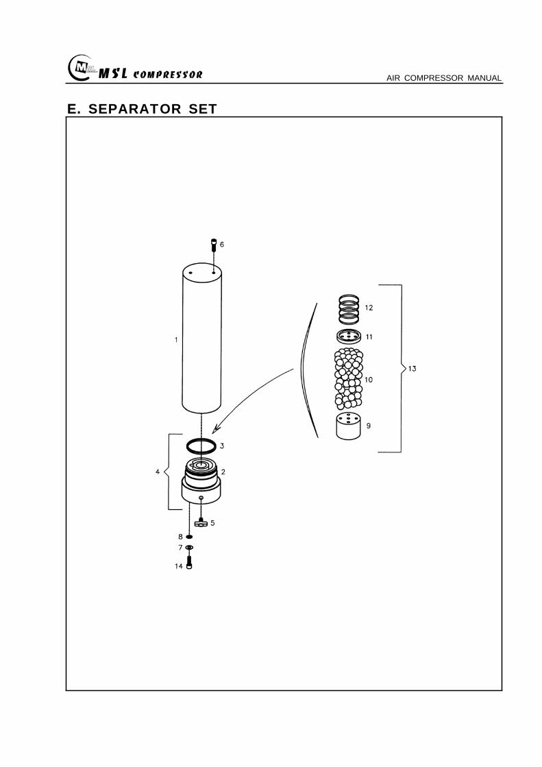
MSL COMPRESSOR AIR COMPRESSOR MANUAL
E SEPARATOR SET
MSL COMPRESSOR AIR COMPRESSOR MANUAL
E SEPARATOR SETKEY No PART No DESCRIPTION (Qty) NOTE
01 B-300-A-023 BODY
02 B-300-A-024 SEPARATOR DOWN CAP
03 B-300-F-003 O-RING
04 B-300-H-013 SEPARATOR DOWN CAP SET
05 B-300-A-024 DRAIN VALVE
06 B-300-B-013 ALLEN SCREW
07 B-300-B-014 WASHER
08 B-300-B-015 SPRING WASHER
09 B-300-A-025 BOTTOM COVER
10 B-300-A-026 BEADS
11 B-300-A-027 TOP COVER
12 B-300-F-004 SPRING
13 B-300-H-014 ELEMENT SET
14 B-300-B-016 ALLEN SCREW
MSL COMPRESSOR AIR COMPRESSOR MANUAL
MSL COMPRESSOR AIR COMPRESSOR MANUAL
MSL COMPRESSOR AIR COMPRESSOR MANUAL
MSL COMPRESSOR AIR COMPRESSOR MANUAL
MEMO
MSL COMPRESSOR AIR COMPRESSOR MANUAL
E SEPARATOR SETKEY No PART No DESCRIPTION (Qty) NOTE
01 B-300-A-023 BODY
02 B-300-A-024 SEPARATOR DOWN CAP
03 B-300-F-003 O-RING
04 B-300-H-013 SEPARATOR DOWN CAP SET
05 B-300-A-024 DRAIN VALVE
06 B-300-B-013 ALLEN SCREW
07 B-300-B-014 WASHER
08 B-300-B-015 SPRING WASHER
09 B-300-A-025 BOTTOM COVER
10 B-300-A-026 BEADS
11 B-300-A-027 TOP COVER
12 B-300-F-004 SPRING
13 B-300-H-014 ELEMENT SET
14 B-300-B-016 ALLEN SCREW
MSL COMPRESSOR AIR COMPRESSOR MANUAL
MSL COMPRESSOR AIR COMPRESSOR MANUAL
MSL COMPRESSOR AIR COMPRESSOR MANUAL
MSL COMPRESSOR AIR COMPRESSOR MANUAL
MEMO
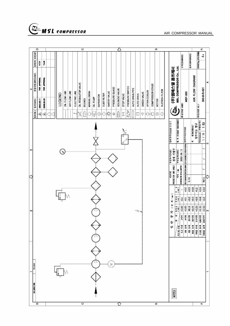
MSL COMPRESSOR AIR COMPRESSOR MANUAL
MSL COMPRESSOR AIR COMPRESSOR MANUAL
MSL COMPRESSOR AIR COMPRESSOR MANUAL
MSL COMPRESSOR AIR COMPRESSOR MANUAL
MEMO
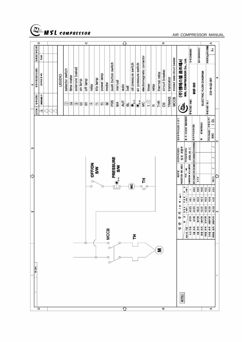
MSL COMPRESSOR AIR COMPRESSOR MANUAL
MSL COMPRESSOR AIR COMPRESSOR MANUAL
MSL COMPRESSOR AIR COMPRESSOR MANUAL
MEMO
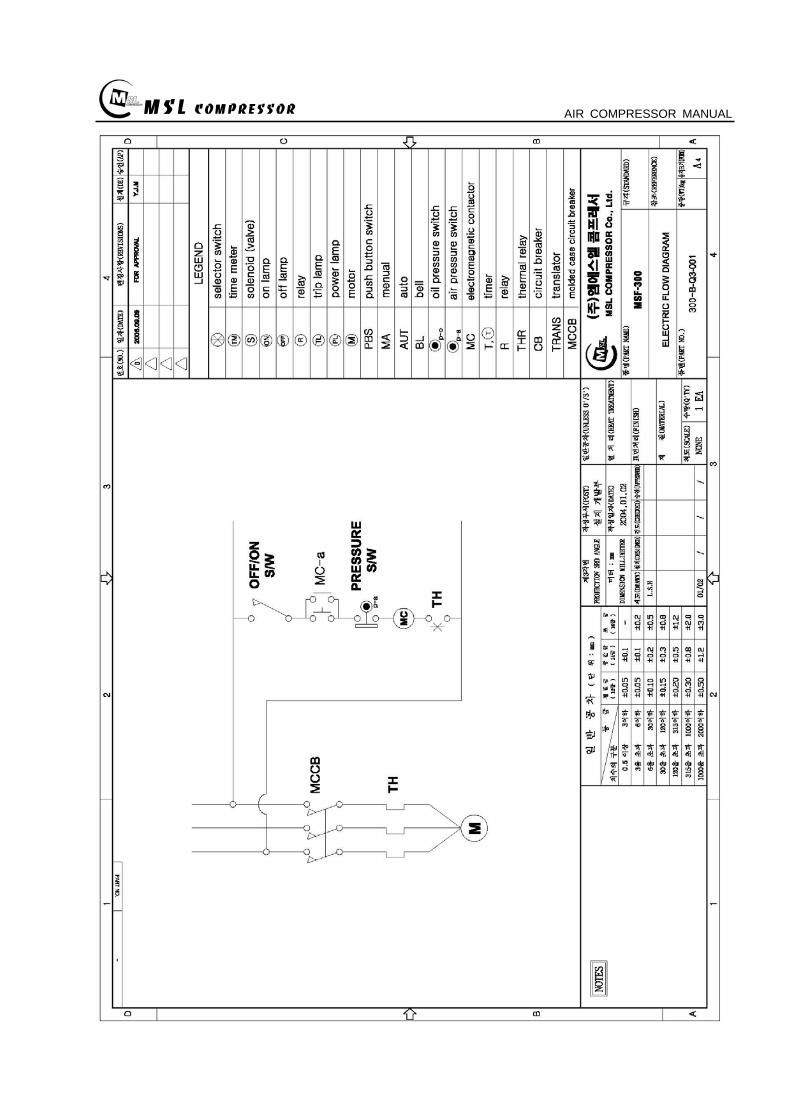
MSL COMPRESSOR AIR COMPRESSOR MANUAL
MSL COMPRESSOR AIR COMPRESSOR MANUAL
MEMO

MSL COMPRESSOR AIR COMPRESSOR MANUAL
MEMO