mse 352 engineering ceramics ii lecture notes · pdf filethe course is intended to teach...
TRANSCRIPT

1
Prepared by: A. Andrews
MSE 352 ENGINEERING CERAMICS II
LECTURE NOTES
OBJECTIVES
The course is intended to teach students studying Materials Science and Engineering the
fundamental science underlying glass technology, namely: the kinetics and conditions necessary for
formation of glass (and glass ceramics), the structure of glass, and the relationship between
structure, composition and properties of glass. The course is also intended to teach students on
cement and concrete technology.
PREREQUISITE
The following courses should be revised.
Principles of Materials Science I & II (MSE 154, MSE 255)
Phase Transformation (MSE 260)
Engineering Ceramics I (MSE 351)
COURSE OUTLINE
Introduction to glasses; The glass state; Theories of glass formation; Kinetics of glass formation;
Kinetic treatment of glass; Glass forming ability and glass stability; Oxide glasses; Properties of
glasses including viscosity, chemical stability, conductivity, and strength; Glass ceramic processing
including raw materials, batch calculations, homogenizing of melts, glass forming, heat treatment of
glasses, glass ceramics and devitrification; Bioactive glasses; Cement, Concrete Technology.
RECOMMENDED BOOKS
1. Materials science and engineering: An introduction, 2010 – W.D. Callister Jr. and D.G.
Rethwisch
2. The science and engineering of materials, 2010 - D.R. Askerland, P.P. Fulay, and W.J.
Wright
3. Fundamentals of Inorganic Glasses. Academic Press, Inc., New York, 1994 - A.K.
Varshneya.
4. Physical Ceramics. – Y.-T Chiang, D.P. Birnie, W.D. Kingery, Wiley, New York, 1997
5. Advances in Ceramics, Volume 18: Commercial Glasses. American Ceramic Society Inc.,
Columbus, Ohio, 1986 - D.C. Boyd and J.F. MacDowell (Editors)
2
Prepared by: A. Andrews
1.0 Introduction
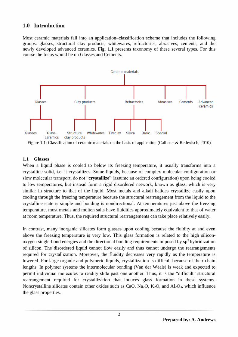
Most ceramic materials fall into an application–classification scheme that includes the following
groups: glasses, structural clay products, whitewares, refractories, abrasives, cements, and the
newly developed advanced ceramics. Fig. 1.1 presents taxonomy of these several types. For this
course the focus would be on Glasses and Cements.
Figure 1.1: Classification of ceramic materials on the basis of application (Callister & Rethwisch, 2010)
1.1 Glasses
When a liquid phase is cooled to below its freezing temperature, it usually transforms into a
crystalline solid, i.e. it crystallizes. Some liquids, because of complex molecular configuration or
slow molecular transport, do not “crystallize” (assume an ordered configuration) upon being cooled
to low temperatures, but instead form a rigid disordered network, known as glass, which is very
similar in structure to that of the liquid. Most metals and alkali halides crystallize easily upon
cooling through the freezing temperature because the structural rearrangement from the liquid to the
crystalline state is simple and bonding is nondirectional. At temperatures just above the freezing
temperature, most metals and molten salts have fluidities approximately equivalent to that of water
at room temperature. Thus, the required structural rearrangements can take place relatively easily.
In contrast, many inorganic silicates form glasses upon cooling because the fluidity at and even
above the freezing temperature is very low. This glass formation is related to the high silicon-
oxygen single-bond energies and the directional bonding requirements imposed by sp3 hybridization
of silicon. The disordered liquid cannot flow easily and thus cannot undergo the rearrangements
required for crystallization. Moreover, the fluidity decreases very rapidly as the temperature is
lowered. For large organic and polymeric liquids, crystallization is difficult because of their chain
lengths. In polymer systems the intermolecular bonding (Van der Waals) is weak and expected to
permit individual molecules to readily slide past one another. Thus, it is the “difficult” structural
rearrangement required for crystallization that induces glass formation in these systems.
Noncrystalline silicates contain other oxides such as CaO, Na2O, K2O, and Al2O3, which influence
the glass properties.

3
Prepared by: A. Andrews
2.0 The Glass State
The properties and chemical composition of the glass used for optical purposes differ greatly from
those of the glass used for baking dishes. Likewise, the glass used for window panes differs from
the glass used for artwork or optical purposes. However, most inorganic glasses have one thing in
common: they are ceramic materials (compounds that contain metallic and non-metallic elements,
most often oxygen) with the amorphous structure of a frozen liquid.
Quartz glass is not crystalline at room temperature because the rearrangement of interatomic bonds
between Si and O required for the establishment of order is impeded: the viscosity of glass is so
high at room temperature that millions of years would be required for it to crystallize. Hence, glass
can be viewed as a perfectly rigid “liquid”, being exceptional in that its extraordinarily high
viscosity slows down its flow properties even on an expanded time scale.
Upon cooling of liquid “glass” we observe that ΔV/ΔT (the contraction with lowering of T)
changes. This may be seen by following the three basic steps in the production of glass:
1. the melting of quartz sand (minute crystals of silica),
2. the shaping of the glass while in a viscous state and
3. the controlled cooling of the shaped article.
The SiO4 tetrahedra in the sand (crystals) are arranged in an ordered pattern (Fig. 2.1), but in the
molten state the crystal matrix breaks up into strings and rings of tetrahedra in irregular patterns
(Fig. 2.2). Because the temperature is very high, the groupings continually break up and reform,
making the mass fluid.
Figure 2.1: Basic Si - O - Si - units as established with sp3 hybridization of Si.
4
Prepared by: A. Andrews
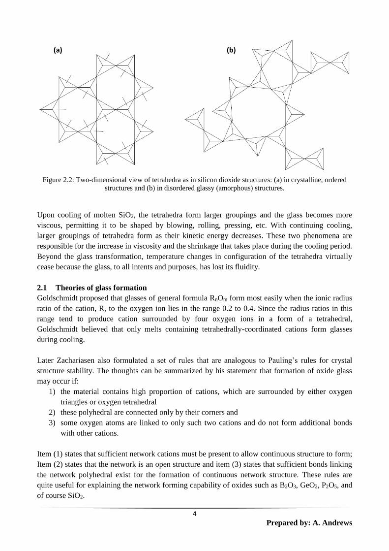
Figure 2.2: Two-dimensional view of tetrahedra as in silicon dioxide structures: (a) in crystalline, ordered
structures and (b) in disordered glassy (amorphous) structures.
Upon cooling of molten SiO2, the tetrahedra form larger groupings and the glass becomes more
viscous, permitting it to be shaped by blowing, rolling, pressing, etc. With continuing cooling,
larger groupings of tetrahedra form as their kinetic energy decreases. These two phenomena are
responsible for the increase in viscosity and the shrinkage that takes place during the cooling period.
Beyond the glass transformation, temperature changes in configuration of the tetrahedra virtually
cease because the glass, to all intents and purposes, has lost its fluidity.
2.1 Theories of glass formation
Goldschmidt proposed that glasses of general formula RnOm form most easily when the ionic radius
ratio of the cation, R, to the oxygen ion lies in the range 0.2 to 0.4. Since the radius ratios in this
range tend to produce cation surrounded by four oxygen ions in a form of a tetrahedral,
Goldschmidt believed that only melts containing tetrahedrally-coordinated cations form glasses
during cooling.
Later Zachariasen also formulated a set of rules that are analogous to Pauling’s rules for crystal
structure stability. The thoughts can be summarized by his statement that formation of oxide glass
may occur if:
1) the material contains high proportion of cations, which are surrounded by either oxygen
triangles or oxygen tetrahedral
2) these polyhedral are connected only by their corners and
3) some oxygen atoms are linked to only such two cations and do not form additional bonds
with other cations.
Item (1) states that sufficient network cations must be present to allow continuous structure to form;
Item (2) states that the network is an open structure and item (3) states that sufficient bonds linking
the network polyhedral exist for the formation of continuous network structure. These rules are
quite useful for explaining the network forming capability of oxides such as B2O3, GeO2, P2O5, and
of course SiO2.
(a) (b)

5
Prepared by: A. Andrews
The replacement of a covalent bond between Si and O by an ionized oxygen and the cation (Na, K
etc.) is the crucial structural change that shortens the effective average chain length. Oddly, in the
borate glasses, the charge redistribution that occurs with alkali additions allows BO4 units to
participate on network formation, thereby increasing average network lengths. This effect explains
the apparent boron anomaly, and the minimum in thermal expansion coefficient that occurs as
alkalis are added to a borate glass.
2.2 Kinetics of glass formation
Crystallization refers to a combination of two processes: nucleation and crystal growth.
Crystallization requires the presence of a nucleus on which the crystals will subsequently grow to a
detectable size. The nucleus may either be homogenous (i.e. forming spontaneously within the melt)
or heterogeneous (i.e. forming at the preexisting surface) such as that due to impurity, crucible wall
etc. if no nuclei are present, crystal growth cannot not occur and the material will form a glass.
Even if some nuclei are present, but no growth has occurred, the extremely small size and low
volume fraction of the nuclei prevents their detection, so that the solid is, for all practical purposes,
still a glass.
The growth step in a phase transformation begins once an embryo has exceeded the critical size, r*,
and becomes a stable nucleus. Note that nucleation will continue to occur simultaneously with
growth of the new phase particles; of course, nucleation cannot occur in regions that have already
transformed to the new phase. Furthermore, the growth process will cease in any region where
particles of the new phase meet, because here the transformation will have reached completion.
2.3 Kinetic treatment of glass formation
Formation of a glass involves cooling from the melt in such a way as to prevent significant crystal
formation. Nucleation and crystal growth occurs simultaneously during cooling of a melt, with rates
that change continuously as the temperature decreases. A pragmatic approach to glass formation
must therefore deal with the interaction between these processes.
Most inorganic glasses can be made to transform from a noncrystalline state to one that is
crystalline by the proper high-temperature heat treatment. This process is called crystallization, and
the product is a fine-grained polycrystalline material that is often called a glass-ceramic. The
formation of these small glass-ceramic grains is, in a sense, a phase transformation, which involves
nucleation and growth stages. As a consequence, the kinetics (i.e., the rate) of crystallization may be
described using the same principles that were applied to phase transformations for metal systems.
For example, dependence of degree of transformation on temperature and time may be expressed
using isothermal transformation (TTT) and continuous cooling transformation (CCT) diagrams. The
continuous cooling transformation diagram for the crystallization of a lunar glass is presented in
Fig. 2.3; the start and end transformation curves on this plot have the same general shape as those
for an iron–carbon alloy of eutectoid composition. Also included are two continuous cooling
curves, which are labelled “1” and “2”; the cooling rate represented by curve 2 is much greater than
that for curve 1. As also noted on this plot, for the continuous cooling path represented by curve 1,
crystallization begins at its intersection with the upper curve, and progresses as time increases and
temperature continues to decrease; upon crossing the lower curve, all of the original glass has
crystallized. The other cooling curve (curve 2) just misses the nose of the crystallization start curve.
It represents a critical cooling rate (for this glass, 100 oC/min)—that is, the minimum cooling rate

6
Prepared by: A. Andrews
for which the final room temperature product is 100% glass; for cooling rates less than this, some
glass ceramic material will form. A nucleating agent (frequently titanium dioxide) is often added to
the glass to promote crystallization. The presence of a nucleating agent shifts the start and end
transformation curves to shorter times.
Figure 2.3: Continuous cooling transformation diagram for the crystallization of a lunar glass (35.5 wt%
SiO2, 14.3 wt% TiO2, 3.7 wt% Al2O3, 23.5 wt% FeO, 11.6 wt% MgO, 11.1 wt% CaO, and 0.2 wt% Na2O).
Also superimposed on this plot are two cooling curves, labelled “1” and “2.”
Thus TTT diagrams must be considered as a model for aiding our understanding of the glass
formation process. This is however, not an experimental tool. Melt viscosity is an important factor
in glass formation. The kinetic barrier to crystallization will be very high if the melt viscosity is
large at the temperature corresponding to the critical cooling rate. Melts which exhibit a large
barrier to nucleation also exhibit good glass forming behaviour. Inhibition of crystal growth due to
factors other than simply high viscosity also improves glass forming behaviour.
2.4 Glass forming ability and glass stability
Glass forming ability is defined in terms of resistance to crystallization of melt during cooling.
Glass forming ability is most important during processes requiring production of an initial glass.
Glass forming ability can be determined by estimating the critical cooling rate required to prevent
crystallization of a specified volume fraction of the sample. For two melts of identical size, the melt
with the smaller cooling rate has a better glass forming ability. A series of compositions can
therefore be ranked in order of improving glass forming ability, by decreasing values of their
critical cooling rates.
Glass stability is defined in terms of resistance to crystallization of glass during heating. Glass
stability is most important during processes involving re-forming of existing glass. Glass stability is
characterized by the difference in temperature between the onset of glass transformation region (Tg)
and the occurrence of crystallization, for a sample heated at a specified linear rate.

7
Prepared by: A. Andrews
2.5 Oxide glasses
The bonding forces responsible for the formation of network structure in crystalline SiO2 produce
similar networks in glasses of other oxides such as B2O3 and P2O5 which are thus also considered as
primary network formers. If an oxide, such as Na2O, is added to silica glass, a bond in the network
is broken and the relatively mobile sodium ion becomes a part of the structure (Fig. 2.4). Examples
of such network modifiers are N2O, K2O, Li2O, CaO, MgO and PbO.
Figure 2.4: Schematic glass networks; (a) SiO
2 network (b) SiO2
network modified through addition of Na2O
With increase in the amount of modifier, the average number of oxygen-silicon bonds forming
bridges between silicon atoms decreases as follows:
O/Si Ratio in Glass Bridging – O-Si Bonds/Si atom
2.0 4 (Fig. 2.4)
2.5 3
3.0 3
The bridging bonds per silicon atom will correspond, for example, to a linear chain structure (Fig.
2.5) and any further increase in modifier will reduce the length of the chain. The principal effect of
a modifier is to lower the melting and working temperature by decreasing the viscosity. An excess
of modifier can make the structural units in the melt sufficiently simple and mobile that
crystallization occurs in preference to the formation of a glass.
Although radius ratios are an excellent guide to the stability of ionic structures and other crystal
structures, the conditions under which glasses are stable require additional criteria as discussed
earlier under theories of glass formation.
8
Prepared by: A. Andrews
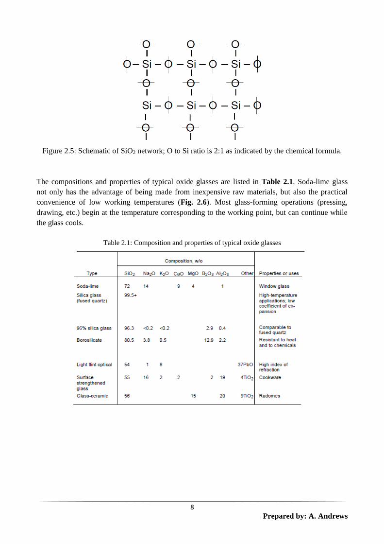
Figure 2.5: Schematic of SiO2 network; O to Si ratio is 2:1 as indicated by the chemical formula.
The compositions and properties of typical oxide glasses are listed in Table 2.1. Soda-lime glass
not only has the advantage of being made from inexpensive raw materials, but also the practical
convenience of low working temperatures (Fig. 2.6). Most glass-forming operations (pressing,
drawing, etc.) begin at the temperature corresponding to the working point, but can continue while
the glass cools.
Table 2.1: Composition and properties of typical oxide glasses
9
Prepared by: A. Andrews
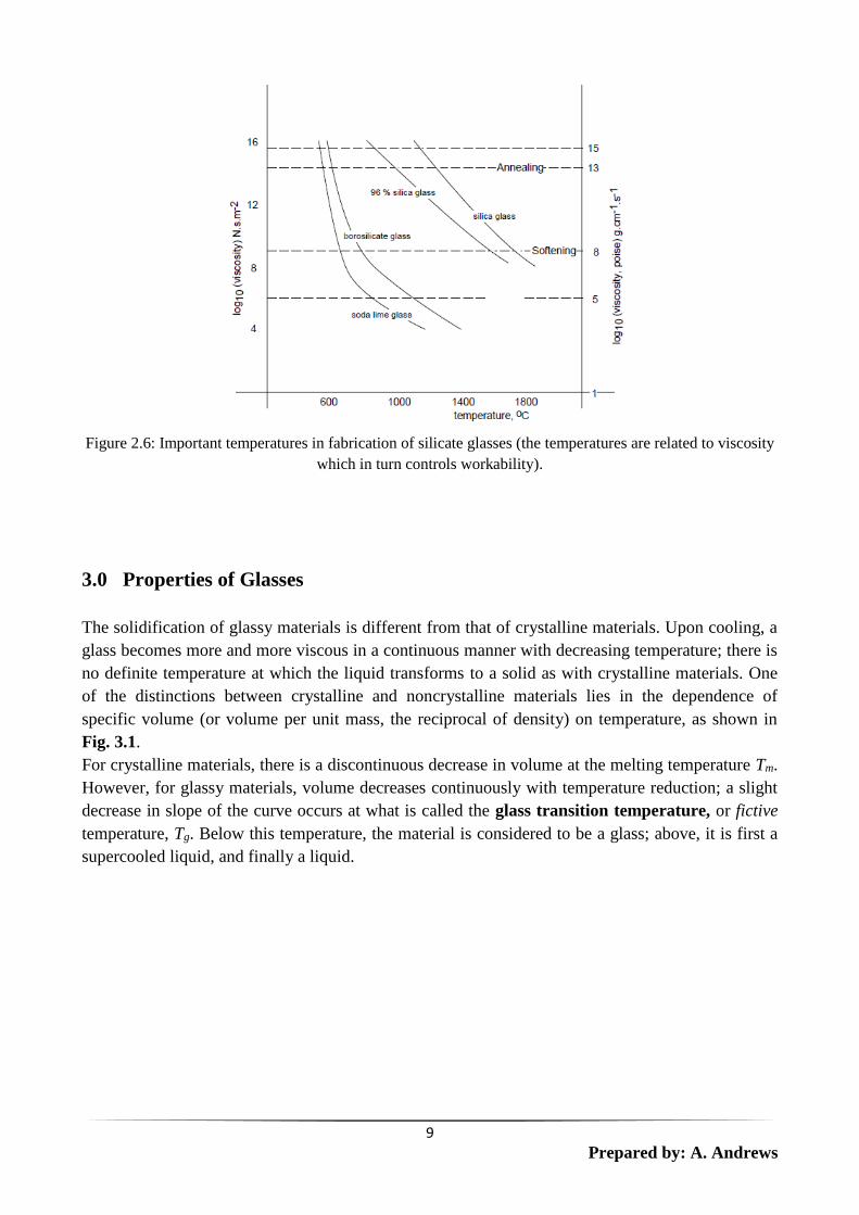
Figure 2.6: Important temperatures in fabrication of silicate glasses (the temperatures are related to viscosity
which in turn controls workability).
3.0 Properties of Glasses
The solidification of glassy materials is different from that of crystalline materials. Upon cooling, a
glass becomes more and more viscous in a continuous manner with decreasing temperature; there is
no definite temperature at which the liquid transforms to a solid as with crystalline materials. One
of the distinctions between crystalline and noncrystalline materials lies in the dependence of
specific volume (or volume per unit mass, the reciprocal of density) on temperature, as shown in
Fig. 3.1.
For crystalline materials, there is a discontinuous decrease in volume at the melting temperature Tm.
However, for glassy materials, volume decreases continuously with temperature reduction; a slight
decrease in slope of the curve occurs at what is called the glass transition temperature, or fictive
temperature, Tg. Below this temperature, the material is considered to be a glass; above, it is first a
supercooled liquid, and finally a liquid.

10
Prepared by: A. Andrews
Figure 3.1: Contrast of specific volume versus temperature behavior of crystalline and noncrystalline
materials. Crystalline materials solidify at the melting temperature Tm. Characteristic of the noncrystalline
state is the glass transition temperature Tg (Callister & Rethwisch, 2010).
3.1 Viscosity of glasses
Also important in glass-forming operations are the viscosity–temperature characteristics of the
glass. The fluidity of liquids (the reciprocal of the viscosity) is a measure of their ability to flow. In
turn, the viscosity (η) (Fig. 3.2) is a measure of their resistance to flow. Viscosity is formulated as
the ratio of the applied stress to the resultant shear strain rate – its dimension is in Newton seconds
per meter squared (Nsm-2).
Figure 3.2: Dimensional analysis of viscosity.
Liquid flow, involving the motion of molecules past one another, requires the breaking and making
of new bonds. Thus the fluidity, like chemical reactions and diffusion in solids is expected to
exhibit exponential temperature dependence and may be modelled as:
11
Prepared by: A. Andrews
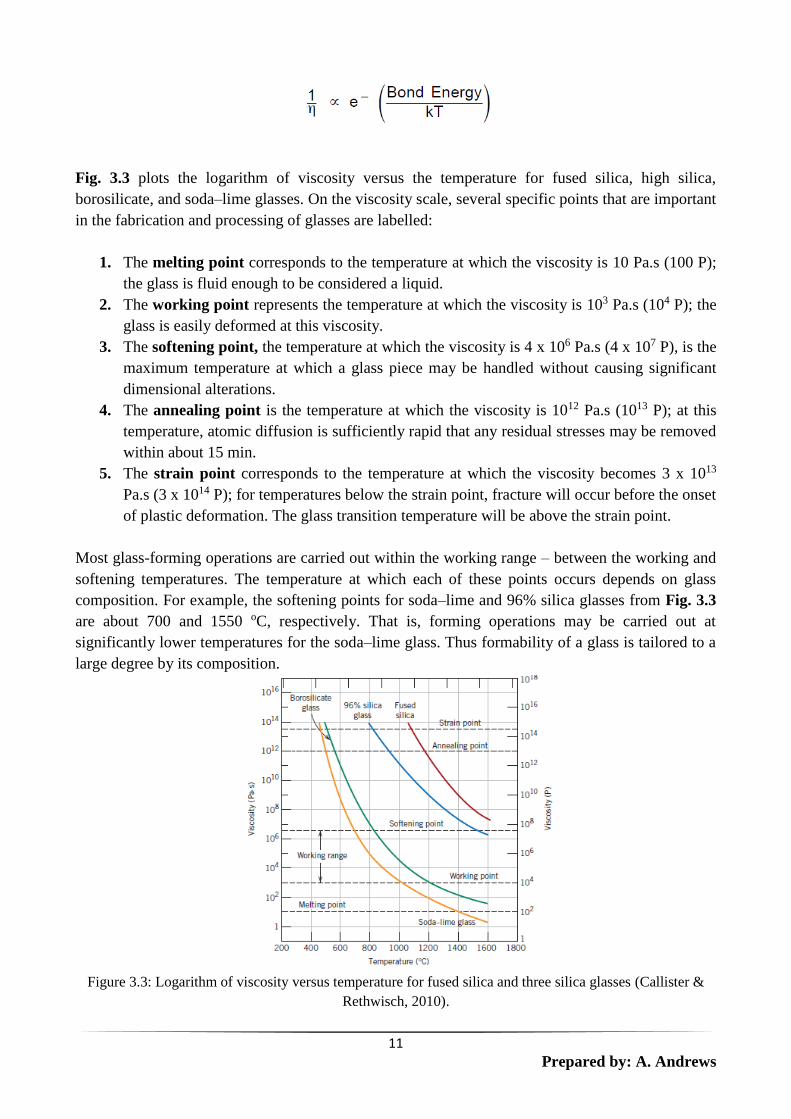
Fig. 3.3 plots the logarithm of viscosity versus the temperature for fused silica, high silica,
borosilicate, and soda–lime glasses. On the viscosity scale, several specific points that are important
in the fabrication and processing of glasses are labelled:
1. The melting point corresponds to the temperature at which the viscosity is 10 Pa.s (100 P);
the glass is fluid enough to be considered a liquid.
2. The working point represents the temperature at which the viscosity is 103 Pa.s (104 P); the
glass is easily deformed at this viscosity.
3. The softening point, the temperature at which the viscosity is 4 x 10⁶ Pa.s (4 x 10⁷ P), is the
maximum temperature at which a glass piece may be handled without causing significant
dimensional alterations.
4. The annealing point is the temperature at which the viscosity is 1012 Pa.s (1013 P); at this
temperature, atomic diffusion is sufficiently rapid that any residual stresses may be removed
within about 15 min.
5. The strain point corresponds to the temperature at which the viscosity becomes 3 x 10¹³
Pa.s (3 x 10¹⁴ P); for temperatures below the strain point, fracture will occur before the onset
of plastic deformation. The glass transition temperature will be above the strain point.
Most glass-forming operations are carried out within the working range – between the working and
softening temperatures. The temperature at which each of these points occurs depends on glass
composition. For example, the softening points for soda–lime and 96% silica glasses from Fig. 3.3
are about 700 and 1550 oC, respectively. That is, forming operations may be carried out at
significantly lower temperatures for the soda–lime glass. Thus formability of a glass is tailored to a
large degree by its composition.
Figure 3.3: Logarithm of viscosity versus temperature for fused silica and three silica glasses (Callister &
Rethwisch, 2010).

12
Prepared by: A. Andrews
3.2 Chemical stability
All glasses are immune to oxidation (decay) because their atoms are fully oxidized. Glass composed
of 100 percent silica tetrahedra is extraordinarily inert. It resists the action of most acids (the most
notable exception is hydrofluoric acid, utilized to etch glass), but it is attacked by strong alkalis (the
bottles containing liquid alkalis on a chemist’s shelf have a clouded surface).
3.3 Conductivity
The ability of a material to conduct electricity is dependent upon the presence of electrons in the
conduction band, separated in glasses by as much as 10 eV from the valence band. Because the
electrons in glass are tightly bonded, glass is a very poor conductor of electricity - in fact, the large
energy gap makes glass an excellent insulator. Glass is also a poor conductor of heat. Thus, hot
common glass may crack when cold water is poured onto it because the surface exposed to the cold
water will shrink while the dimensions of the interior remain unaffected.
3.4 Strength
Glass is harder than many types of steel and is also very elastic, as evidenced by the speed and
accuracy with which glass marbles rebound when they meet. Glass has “no” crystal structure, and
hence the phenomenon of slip cannot take place. This, together with the strong bonding between
atoms, gives glass a very high compressive strength and a theoretical tensile strength of about 107
kN/m2 (significantly higher than that of steel). Glass fibers with an actual tensile strength of 4 x 10⁷
kN/m2 have been produced. Since glass has a “liquid structure” it may be considered “saturated with
dislocations”.
If a piece of metal has a very high dislocation density (e.g., due to cold working) the dislocations
interfere with each other’s movements. Therefore, with increasing dislocation density a piece of
metal becomes harder and stronger, but also more brittle.
Since the molecular structures in glass are unable to move, the presence of minute cracks or
imperfections in glass permits stress concentrations to localize and exceed the bond strength
between atoms - common glass will crack. Thus, in actual practice, the strength of glass is, by a
factor of 100 to 1000, less than the theoretical strength, and glass is brittle. For example, a freshly
made electric light bulb may not crack when initially dropped, but its surface becomes damaged
and, after it rebounds and strikes the floor a few more times, it breaks.
The inherent high strength of fibrous glass is utilized in the fiberglass sections employed for boats
and automobile bodies. Before being pressed into shape, fiberglass is mixed with a synthetic resin
which serves to protect the fibers from scratching. Since the fibers thus retain their high strength,
fiberglass sections are very strong for their weight.

13
Prepared by: A. Andrews
4.0 Glass Ceramic Processing
4.1 Raw materials
Glass is produced by heating the raw materials to an elevated temperature above which melting
occurs. Most commercial glasses are of the silica–soda–lime variety; the silica is usually supplied as
common quartz sand, whereas Na2O and CaO are added as soda ash (Na2CO3) and limestone
(CaCO3). For most applications, especially when optical transparency is important, it is essential
that the glass product be homogeneous and pore free. Homogeneity is achieved by complete
melting and mixing of the raw ingredients. Porosity results from small gas bubbles that are
produced; these must be absorbed into the melt or otherwise eliminated, which requires proper
adjustment of the viscosity of the molten material.
It is important that during the melting of the components of glass (high quality silica sands, soda
ash, modifying oxides), adequate mixing in what are often relatively viscous melts (compared with
metals), are ensured and remove product on a continuous or semi-continuous basis. Recycled glass
is useful in order to provide a low melting point material (the cullet) that then dissolves the solid
oxides in the feedstock (silica, alumina, soda ash). Gas fired reverberatory furnaces are typical,
although electrical heating is also very useful, especially if it is important to avoid contamination.
Mixing is a significant challenge and additives such as sulphate powders are used ("fining") to
provide large volumes of gas bubbles which provide a strong stirring action. Refractories are very
important to glass melting furnaces: high temperature oxides such as zirconia-alumina-silica
mixtures are used. For very high purity systems, platinum crucibles are used, e.g. glass fibers. The
names of many of the raw materials and their compositions are listed in Table 4.1. Gravimetric
factors which allow calculation of the yield of the desired glass component for each weight unit of
raw material are also listed in the table.
Table 4.1: Raw materials for glass making
Common Name Nominal Composition Gravimetric Factor
Albite Feldspar Na2O-Al2O3-6SiO2 Na2O=8.46; Al2O3=5.14; SiO2=1.45
Alumina Al2O3 Al2O3=1.00
Anorthite feldspar CaO-Al2O3-2SiO2 CaO=4.96; Al2O3=2.73; SiO2=2.32
Whiting CaCO3 CaO=1.79
Dolomite CaCO3-MgCO3 CaO=3.29; MgO=4.58
Bone ash 3CaO-P2O5 CaO=1.84; P2O5=2.19
Borax Na2O-B2O3.10H2O Na2O=6.14; B2O3=2.74
Regardless of the source of the components used to produce a specific glass, the batch materials can
be divided into five categories on the basis of their role in the process: glassformer, flux, property
modifier, colorant and fining agent.
The same compound may be classed into different categories when used for different purposes. The
most essential component of any glass batch is the glassformer. They are also called network
formers or glass forming oxides in many glass oxides. The identity of these components usually

14
Prepared by: A. Andrews
serves as the basis for the generic name used for the glass. For example, silicate glass means the
glassformer is silica. Borosilicate means major components are boric acid and silica.
Fluxes reduce the processing temperature within acceptable limits. The most common fluxes
include alkaline oxides (Na2O) and PbO. The use of PbO is being discouraged due to environmental
concerns. While addition of fluxes decreases cost of glass formation, the addition of large amount
of alkali oxides results in serious degradation in many properties. Degradation in properties is
usually countered by addition of property modifier which includes alkaline earth and transition
metal oxides and most importantly aluminium oxide.
Colorants are used to control the colour of the final glass product. In most cases, colorants are
oxides of either the 3rd transition metals or the 4f rare earths. Gold and silver are used to produce
colours by formation of colloids in glasses. When colorants are used to counteract the effect of
other colorants to produce slightly grey glass, they are referred to as decolourant.
Fining agents are added to glass forming batches to promote the removal of bubbles from the melt.
Fining agents include the arsenic and antimony oxides, potassium and sodium nitrates, NaCl,
fluorides such as CaF2, NaF and Na3AlF6. These materials are present in small quantities (<1wt%).
4.2 Batch calculations
Glass batch calculations can range from very simple to very complex, as a function of the
complexity of composition and the raw material used to prepare the mixture.
Steps for batch calculation:
1. Determine the molecular weight of each component required to produce the desired molar
composition
2. Multiply the molecular weight by the mass fraction of each component
3. Total these contributions to determine the molecular weight of the glass
4. Divide each individual contribution by molecular weight of the glass to determine the
weight fraction of each component
5. Multiply the weight fraction of each component by the amount of glass to be produced
6. The batch weight of any component which decomposes during melting is adjusted by
multiplying the weight fraction of that component by appropriate gravimetric factor for the
raw material actually used in the batch.
Work examples
15
Prepared by: A. Andrews
4.3 Homogenizing of melt
The fluid produced during the initial batch decomposition process is very heterogeneous. This
heterogeneity is gradually reduced by stirring action of rising bubbles during the firing process.
Production of acceptable homogenous glass requires additional time for diffusion process to
improve the homogeneity of the melt. Gross defects such as bubbles, seed and stones (particles of
undissolved materials) are often clearly visible and results in rejection of commercial glasses.
Density and refractive index measurements on crushed glasses are used as relative measurement of
intensity of inhomogeneity of glass. Poor homogeneity frequently results from poor mixing of the
original batch materials.
4.4 Glass forming
Five different forming methods are used to fabricate glass products: pressing, blowing, drawing,
sheet and fiber forming. Pressing is used in the fabrication of relatively thick-walled pieces such as
plates and dishes. The glass piece is formed by pressure application in a graphite-coated cast iron
mould having the desired shape; the mould is ordinarily heated to ensure an even surface.
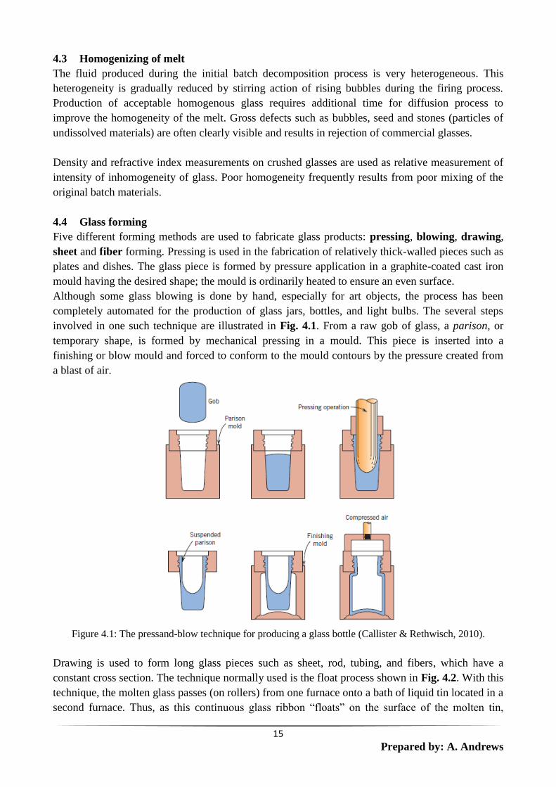
Although some glass blowing is done by hand, especially for art objects, the process has been
completely automated for the production of glass jars, bottles, and light bulbs. The several steps
involved in one such technique are illustrated in Fig. 4.1. From a raw gob of glass, a parison, or
temporary shape, is formed by mechanical pressing in a mould. This piece is inserted into a
finishing or blow mould and forced to conform to the mould contours by the pressure created from
a blast of air.
Figure 4.1: The pressand-blow technique for producing a glass bottle (Callister & Rethwisch, 2010).
Drawing is used to form long glass pieces such as sheet, rod, tubing, and fibers, which have a
constant cross section. The technique normally used is the float process shown in Fig. 4.2. With this
technique, the molten glass passes (on rollers) from one furnace onto a bath of liquid tin located in a
second furnace. Thus, as this continuous glass ribbon “floats” on the surface of the molten tin,

16
Prepared by: A. Andrews
gravitational and surface tension forces cause the faces to become perfectly flat and parallel and the
resulting sheet to be of uniform thickness.
Furthermore, sheet faces acquire a bright “fire-polished” finish in one region of the furnace. The
sheet next passes into an annealing furnace (lehr), and is finally cut into sections. The success of
this operation requires rigid control of both temperature and chemistry of the gaseous atmosphere.
Figure 4.2: Schematic diagram showing the float process for making sheet glass (Callister & Rethwisch,
2010)
4.5 Heat treatment of glasses
Annealing of glass
When a ceramic material is cooled from an elevated temperature, internal stresses, called thermal
stresses, may be introduced as a result of the difference in cooling rate and thermal contraction
between the surface and interior regions. These thermal stresses are important in brittle ceramics,
especially glasses, because they may weaken the material or, in extreme cases, lead to fracture,
which is termed thermal shock. In order to relieve the internal stresses that may develop during
glass formation, all commercial glassware is annealed (slowly cooled) immediately after shaping.
This slow cooling operation is carried out in industry by placing the shaped objects on a conveyor
belt which transports them first through a reheating zone (annealing point) and then through
sections having successively lower temperatures in a furnace called the lehr to room temperature.
Strengthened glass
The glass scientist has produced objects made of glass which can be struck with a hammer or
dropped from a tall building without breaking. Two techniques are employed in strengthening glass
- one physical (glass tempering) and one chemical (ion exchange). Both techniques are based on
the fact that, when there is the slightest imperfection (minute scratch) on the surface, glass remains
extraordinarily strong in compression but becomes weak in tension. Thus the strengthening
treatment consists of prestressing a glass object by inducing compressive strains in its exterior and
thereby enabling it to counteract any tensile stresses which develop under tension.

17
Prepared by: A. Andrews
In physical prestressing, the shaped object is heated to just below its softening point (surface flaws
are annealed out) and its surface is then chilled by means of a blast of air or an oil bath. Under these
conditions the exterior of the glass cools and contracts immediately, but since glass is a poor
conductor of heat the interior will not contract. The glass will not crack because the interior remains
plastic. When the interior starts to cool, it cannot contract because the exterior has already set, but,
in attempting to contract, the interior continues to draw the exterior together. A built-in compressive
stress then develops in the outer layers of the glass. When a tensile stress is applied to this glass, it
is counteracted by these compressive stresses. Thus the prestressed glass will not shatter until the
surface compression is exceeded. As long as its surface remains intact, prestressed glass continues
to be strong and shock-resistant. However, if a deep scratch develops on the surface, the tensile
stresses set up in the interior by the surface compression are released and the glass will shatter into
thousands of tiny particles. Therefore prestressed articles must be cut to exact size and all holes
drilled prior to prestressing. Among the many uses for this type of glass are plate-glass doors, side
windows of automobiles and eyeglass lenses.
Ion exchange is a chemical technique for prestressing glass objects. The first step is to place the
shaped object into a molten salt bath containing potassium ions, which replace the sodium ions on
the surface of the glass. The potassium ions are larger than the sodium ions and, in accommodating
them, the surface of the glass becomes more crowded - thus inducing compressive strains on the
exterior. Glass of this type, characterized by very high strength, is useful for a great variety of
applications. Its flexural strength can be as high as 106 kN/m2
compared with 105 kN/m2
for
untreated glass.
4.6 Recrystallized glass (glass ceramics)
Recrystallized glass, also known as polycrystalline glass, is commonly produced by adding
nucleating agents to the glass batch. Subsequently the glass can be formed into a desired shape by
any of the conventional glass forming processes (e.g. blowing and drawing) and then be heat-treated
to promote recrystallization. One such set of heat treatments for a Li2O–Al2O3–SiO2 glass-ceramic
is detailed in the time-versus-temperature plot of Fig. 4.3. After melting and forming operations,
nucleation and growth of the crystalline phase particles are carried out isothermally at two different
temperatures. Recrystallized glass possesses increased impact strength, hardness and thermal shock
resistance compared with conventional non-crystalline glasses. One common place application of a
recrystallized glass is in the manufacture of the so-called refrigerator-to-oven cooking dishes.
4.7 Devitrification of glass
Under certain conditions glass will become “contaminated” with crystalline particles. A glass in this
condition is termed devitrified, which is simply another way of stating that it has partially or
completely crystallized. Devitrified glass, unless of the very special variety that is deliberately
produced, is undesirable since the crystalline areas form large crystals and are extremely weak and
brittle, as well as being translucent only. Crystalline segregations in glass are known as stones.

18
Prepared by: A. Andrews
Figure 4.3: Typical time-versus-temperature processing cycle for a Li2O–Al2O3–SiO2 glass-ceramic
(Callister & Rethwisch, 2010).
5.0 Bioactive Glasses
Bioactive material: A material that elicits a specific biological response at the interface of the
material, resulting in the formation of a bond between the tissues and the material.
Materials that can be classified as bioceramics include alumina, zirconia, calcium phosphates, silica
based glasses or glass ceramics, and pyrolytic carbons
The use of bioceramics has become very important in recent times because of the many advantages
they possess. Bioceramics are inert in the body (or bioactive in the body), chemically inert in many
environments, high wear resistance (orthopaedic and dental applications), high modulus and
compressive strengths, and has esthetic value for dental applications. They are however, brittle, has
low tensile strength (except fibers) and poor fatigue resistance.
Bioceramics are available as micro‐spheres, thin layers or coatings on a metallic implant, porous
networks, composites with a polymer component, and large well polished surfaces.
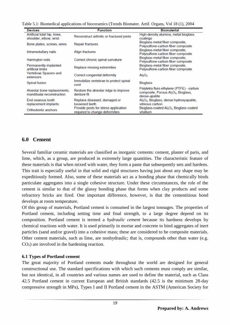
Bone is considered as one of the natural ceramic composites. The mineral component of bone is
hydroxyapatite (Ca5(PO4)3OH). The apatite (reinforcement) is brittle whilst the soft part (matrix) is
collagen. Hence synthetic calcium phosphates are used as biomaterials. Basic application areas
include its use as orthopaedic – bone plates and screws, total and partial hip components, coatings
of metal prostheses for controlled implant/tissue interfacial response, space filling of diseased bone,
vertebra prostheses and vertebra spacers. Table 5.1 summarizes some of the application areas of
bioceramics.
19
Prepared by: A. Andrews
Table 5.1: Biomedical applications of bioceramics (Trends Biomater. Artif. Organs, Vol 18 (1), 2004
6.0 Cement
Several familiar ceramic materials are classified as inorganic cements: cement, plaster of paris, and
lime, which, as a group, are produced in extremely large quantities. The characteristic feature of
these materials is that when mixed with water, they form a paste that subsequently sets and hardens.
This trait is especially useful in that solid and rigid structures having just about any shape may be
expeditiously formed. Also, some of these materials act as a bonding phase that chemically binds
particulate aggregates into a single cohesive structure. Under these circumstances, the role of the
cement is similar to that of the glassy bonding phase that forms when clay products and some
refractory bricks are fired. One important difference, however, is that the cementitious bond
develops at room temperature.
Of this group of materials, Portland cement is consumed in the largest tonnages. The properties of
Portland cement, including setting time and final strength, to a large degree depend on its
composition. Portland cement is termed a hydraulic cement because its hardness develops by
chemical reactions with water. It is used primarily in mortar and concrete to bind aggregates of inert
particles (sand and/or gravel) into a cohesive mass; these are considered to be composite materials.
Other cement materials, such as lime, are nonhydraulic; that is, compounds other than water (e.g.
CO2) are involved in the hardening reaction.
6.1 Types of Portland cement
The great majority of Portland cements made throughout the world are designed for general
constructional use. The standard specifications with which such cements must comply are similar,
but not identical, in all countries and various names are used to define the material, such as Class
42.5 Portland cement in current European and British standards (42.5 is the minimum 28-day
compressive strength in MPa), Types I and II Portland cement in the ASTM (American Society for

20
Prepared by: A. Andrews
Testing and Materials) specifications used in the USA, or Ordinary Portland Cement (OPC) in
former British standards.
Standard specifications are, in general, based partly on chemical composition or physical properties
such as specific surface area, and partly on performance tests, such as setting time or compressive
strength developed under standard conditions. The content of MgO is usually limited to 4-5%,
because quantities of this component in excess of about 2% can occur as periclase (magnesium
oxide), which through slow reaction with water can cause destructive expansion of hardened
concrete.
Free lime (calcium oxide) can behave similarly. Excessive contents of SO3 can also cause
expansion, and upper limits, typically 3.5% for ordinary Portland cements, are usually imposed.
Alkalis (K2O and Na2O) can undergo expansive reactions with certain aggregates, and some
specifications limit the content, e.g. to 0.6% equivalent Na2O (Na2O + 0.66 K2O).
Other upper limits of composition widely used in specifications relate to matter insoluble in dilute
acid, and loss on ignition. Many other minor components are limited in content by their effects on
the manufacturing process, or the properties, or both, and in some cases the limits are defined in
specifications.
Rapid-hardening Portland cements have been produced in various ways, such as varying the
composition to increase the alite content, finer grinding of the clinker, and improvements in the
manufacturing process, e.g. finer grinding or better mixing of the raw materials. The alite contents
of Portland cements have increased steadily over the one and a half centuries during which the latter
have been produced, and many cements that would be considered ordinary today would have been
described as rapid hardening only a few decades ago. In the ASTM specifications, rapid-hardening
Portland cements are called high early strength or Type III cements. For both ordinary and rapid-
hardening cements, both lower and upper limits may be imposed on strengths at 28 days, upper
limits being a safeguard against poor durability resulting from the use of inadequate cement
contents in concrete.
Destructive expansion from reaction with sulphates can occur not only if the latter are present in
excessive proportion in the cement, but also from attack on concrete by sulphate solutions. The
reaction involves the A12O3-containing phases in the hardened cement, and in sulphate-resisting
Portland cements its effects are reduced by decreasing the proportion of the aluminates phase,
sometimes to zero. This is achieved by decreasing the ratio of A12O3 to Fe2O3 in the raw materials.
In the USA, sulphate resisting Portland cements are called Type V cements.
White Portland cements are made by increasing the ratio of A12O3 to Fe2O3, and thus represent the
opposite extreme in composition to sulfate resisting Portland cements. The normal, dark colour of
Portland cement is due to the ferrite, formation of which in a white cement must thus be avoided. It
is impracticable to employ raw materials that are completely free from Fe2O3 and other
components, such as Mn2O3, that contribute to the colour. The effects of these components are
therefore usually minimized by producing the clinker under slightly reducing conditions and by
rapid quenching. In addition to alite, belite and aluminate, some glass may be formed.
21
Prepared by: A. Andrews
The reaction of Portland cement with water is exothermic, and while this can be an advantage under
some conditions because it accelerates hardening, it is a disadvantage under others, such as in the
construction of large dams or in the lining of oil wells, when a cement slurry has to be pumped over
a large distance under pressure and sometimes at a high temperature. Slower heat evolution can be
achieved by coarser grinding, and decreased total heat evolution by lowering the contents of alite
and aluminate. The ASTM specifications include definitions of a Type II or 'moderate heat of
hardening' cement, and a more extreme Type IV or 'low heat' cement. The Type II cement is also
suitable for conditions exposed to moderate sulfate attack, and is widely used in general
construction work. Heat evolution can also be decreased by partially replacing the cement by flyash
(pulverized fuel ash; PFA).
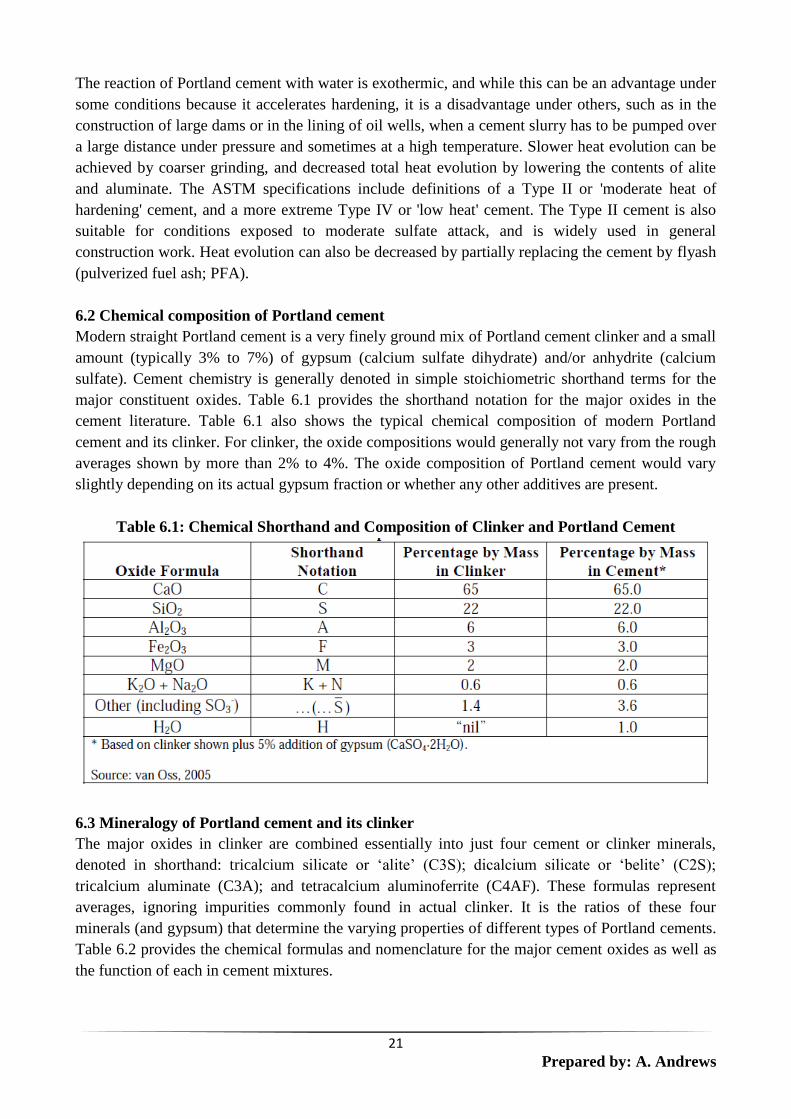
6.2 Chemical composition of Portland cement
Modern straight Portland cement is a very finely ground mix of Portland cement clinker and a small
amount (typically 3% to 7%) of gypsum (calcium sulfate dihydrate) and/or anhydrite (calcium
sulfate). Cement chemistry is generally denoted in simple stoichiometric shorthand terms for the
major constituent oxides. Table 6.1 provides the shorthand notation for the major oxides in the
cement literature. Table 6.1 also shows the typical chemical composition of modern Portland
cement and its clinker. For clinker, the oxide compositions would generally not vary from the rough
averages shown by more than 2% to 4%. The oxide composition of Portland cement would vary
slightly depending on its actual gypsum fraction or whether any other additives are present.
Table 6.1: Chemical Shorthand and Composition of Clinker and Portland Cement
6.3 Mineralogy of Portland cement and its clinker
The major oxides in clinker are combined essentially into just four cement or clinker minerals,
denoted in shorthand: tricalcium silicate or ‘alite’ (C3S); dicalcium silicate or ‘belite’ (C2S);
tricalcium aluminate (C3A); and tetracalcium aluminoferrite (C4AF). These formulas represent
averages, ignoring impurities commonly found in actual clinker. It is the ratios of these four
minerals (and gypsum) that determine the varying properties of different types of Portland cements.
Table 6.2 provides the chemical formulas and nomenclature for the major cement oxides as well as
the function of each in cement mixtures.

22
Prepared by: A. Andrews
As indicated in Table 6.2, some of the minerals in clinker serve different functions in the
manufacturing process while others impart varying final properties to the cement. The proportion of
C3S, for example, determines the degree of early strength development of the cement. The “ferrite”
mineral’s (C4AF) primary purpose, on the other hand, is to lower the temperature required in the
kiln to form the C3S mineral, and really does not impart a specific property to the cement.
Table 6.3 presents the common mineralogical compositions of Types I through IV cements and the
unique properties of each type.
Table 6.2: Typical Mineralogical Composition of Modern Portland Cement
Table 6.3 Typical Range in Mineral Composition in Portland Cements
23
Prepared by: A. Andrews
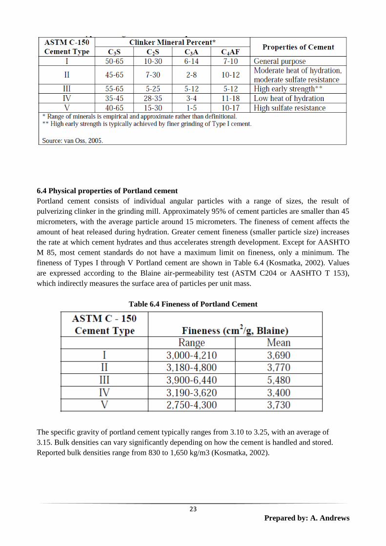
6.4 Physical properties of Portland cement
Portland cement consists of individual angular particles with a range of sizes, the result of
pulverizing clinker in the grinding mill. Approximately 95% of cement particles are smaller than 45
micrometers, with the average particle around 15 micrometers. The fineness of cement affects the
amount of heat released during hydration. Greater cement fineness (smaller particle size) increases
the rate at which cement hydrates and thus accelerates strength development. Except for AASHTO
M 85, most cement standards do not have a maximum limit on fineness, only a minimum. The
fineness of Types I through V Portland cement are shown in Table 6.4 (Kosmatka, 2002). Values
are expressed according to the Blaine air-permeability test (ASTM C204 or AASHTO T 153),
which indirectly measures the surface area of particles per unit mass.
Table 6.4 Fineness of Portland Cement
The specific gravity of portland cement typically ranges from 3.10 to 3.25, with an average of
3.15. Bulk densities can vary significantly depending on how the cement is handled and stored.
Reported bulk densities range from 830 to 1,650 kg/m3 (Kosmatka, 2002).

24
Prepared by: A. Andrews
6.5 Clinker manufacturing process
Portland cement manufacturing is a two-step process beginning with the manufacture of clinker
followed by the fine grinding of the clinker with gypsum and other additives to make the finished
cement product. Grinding can occur on site or at offsite grinding plants. The first step in clinker
manufacture is the quarrying, crushing, and proportioning of raw materials. Due to the low unit
value of these raw materials, they typically are mined within a few miles of the cement plant. The
cost of transport renders long-distance transport of these low-cost raw materials uneconomical.
Once the raw mix, or raw meal, is prepared, it is fed into a cement kiln and converted into the
clinker minerals through a thermochemical conversion, referred to as pyroprocessing because it
involves direct flame interaction. Figure 6.1 provides a generalized flow diagram of the cement
manufacturing process (van Oss, 2005).
The raw materials for clinker manufacture consist primarily of materials that supply four primary
oxides: Calcium oxide (CaO), silicon dioxide (SiO2), aluminum oxide (Al2O3), and ferric oxide
(Fe2O3). The composition of the raw mix typically includes about 80% calcium carbonate, about
10% to 15% silica, and small amounts of alumina and iron. Depending on the quality and quantity
of these oxides available to the facility, other raw materials, referred to as accessory or sweetener
materials, are added to correct for any deficiencies in the primary raw materials.
Certain types of fuel burned in the cement kiln can also contribute oxides (e.g., ash from coal
combustion contributes silica oxides, steel belts in waste tires contribute iron oxide).
Figure 6.1: Cement Manufacturing Flow Diagram
Calcium oxide (CaO or simply C in shorthand) is the primary ingredient in clinker, comprising
about 65% of clinker by mass. A cement plant typically examines its source of C (typically
limestone, marl, or chalk) and determines what other oxides need to be added to achieve the desired
clinker composition. Clay, shale, slate, or sand provide the silica and alumina component, while
iron, mill scale, or other ferrous materials provide the iron content. Preparing the raw mix for
clinker production requires constant sampling, chemical testing, and adjusting of the inputs to
maintain the desired clinker composition.
On average, it takes about 1.7 tons of nonfuel raw materials to produce 1 ton of clinker. Of the 1.7
tons of raw materials, approximately 1.5 tons is limestone or calcium oxide rich rock (van Oss,
2005). The lost mass takes the form of carbon dioxide (CO2) driven off by the calcination of

25
Prepared by: A. Andrews
limestone and the generation of CKD (Cement Kiln Dust). Nearly one ton of CO2 is produced for
every ton of clinker manufactured (van Oss, 2005). The CKD that is produced during clinker
manufacture is carried “up the stack” and captured by emission control devices. A large portion of
the CKD, though not all of it, is returned to the kiln as part of the feed stream.
After clinker has been cooled to about 100°C, it is ready to be ground into finished cement in a
grinding mill, more commonly referred to as a finish mill. Generally, separate grinding and/or
blending finish mill lines will be maintained at a plant for each of its major product classes (finished
Portland cements, blended cements, masonry cements, ground slag). Additives that commonly
require grinding at the mill include gypsum, limestone, granulated blast furnace slag, and natural
pozzolans. Additives that generally do not require significant grinding include coal fly ash, GGBFS,
and silica fume, but the finish mill does provide intimate mixing of these with the Portland cement
base.
7.0 Concrete
Concrete is a common large-particle composite in which both matrix and dispersed phases are
ceramic materials. Concrete and cement are sometimes incorrectly interchanged. In a broad sense,
concrete implies a composite material consisting of an aggregate of particles that are bound together
in a solid body by some type of binding medium, that is, a cement. The two most familiar concretes
are those made with Portland and asphaltic cements, in which the aggregate is gravel and sand.
Asphaltic concrete is widely used primarily as a paving material, whereas Portland cement concrete
is employed extensively as a structural building material.
7.1 Portland cement concrete
The ingredients for this concrete are Portland cement, a fine aggregate (sand), a coarse aggregate
(gravel), and water. The aggregate particles act as a filler material to reduce the overall cost of the
concrete product because they are cheap, whereas cement is relatively expensive. To achieve the
optimum strength and workability of a concrete mixture, the ingredients must be added in the
correct proportions. Dense packing of the aggregate and good interfacial contact is achieved by
having particles of two different sizes; the fine particles of sand should fill the void spaces between
the gravel particles. Ordinarily these aggregates constitute between 60% and 80% of the total
volume. The amount of cement–water paste should be sufficient to coat all the sand and gravel
particles; otherwise, the cementitious bond will be incomplete. Furthermore, all the constituents
should be thoroughly mixed. Complete bonding between cement and the aggregate particles is
contingent on the addition of the correct quantity of water. Too little water leads to incomplete
bonding and too much result in excessive porosity; in either case, the final strength is less than the
optimum.
The character of the aggregate particles is an important consideration. In particular, the size
distribution of the aggregates influences the amount of cement–water paste required. Also, the
surfaces should be clean and free from clay and silt, which prevent the formation of a sound bond at
the particle surface.
Portland cement concrete is a major material of construction, primarily because it can be poured in
place and hardens at room temperature, and even when submerged in water. However, as a
structural material, it has some limitations and disadvantages. Like most ceramics, Portland cement

26
Prepared by: A. Andrews
concrete is relatively weak and extremely brittle; its tensile strength is approximately one-fifteenth
to one-tenth its compressive strength. Also, large concrete structures can experience considerable
thermal expansion and contraction with temperature fluctuations. In addition, water penetrates into
external pores, which can cause severe cracking in cold weather as a consequence of freeze–thaw
cycles. Most of these inadequacies may be eliminated or at least improved by reinforcement and/or
the incorporation of additives.