msd enhancer ignition, pn 4255 · msd enhancer ignition, pn 4255 for 1997 sea-doo® spx, gtx...
TRANSCRIPT
MSD IGNITION • 12120 ESTHER LAMA, SUITE 114, EL PASO, TEXAS 79936 • (800) 392-2842 • FAX (915) 858-9241
® Registered Trademark of Bombardier Inc.
MSD ENHANCER IGNITION, PN 4255FOR 1997 SEA-DOO® SPX, GTX
INSTALLATION HARNESS, PN 42551
Parts Included3 - Female Bullet Connector 1 - Yellow Jumper3 - Male Bullet Connector 1 - White Jumper1 - Red Jumper 1 - Purple/Black Jumper1 - Black Jumper
This Installation manual outlines the wiring of the MSD PN 4255 Enhancer to a 1997 SEA-DOOwatercraft. Timing controls and programming are explained in the PN 4255 Instruction Manual.
This installation eliminates the stock SEA-DOO ignition and MPEM module and requires cuttingand splicing of the existing wires. The installation is recommended for experienced mechanicsthat are capable of performing these type of modifications.
IMPORTANT: After installing the MSD Enhancer Ignition, PN 4255, the stock start/stop switchwill no longer function as a stop switch. To turn the engine off, the stock lanyard must be usedas the ignition kill function.
INSTALLATION ON 1997 CRAFTS
Refer to the PN 4255 Installation Instructions for removal of the stock ignition/MPEM module.The MSD Enhancer mounts in the same location with the supplied retaining bracket.
Note: The following wiring connections are for installation on a 1997 SEA-DOO SPX or GTXonly.
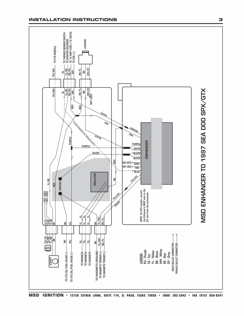
BK/YL wire from the magneto trigger pickup (-).Remove BK/YL wire from ground stud and cut off ring lug. Attach a female bullet connector tothe BK/YL wire and connect it to the Enhancer’s GREEN wire.
YL/WH wire from the magneto trigger pickup (+).Cut the 6-Pin Sumitomo connector off the Enhancer Ignition. Crimp the supplied YELLOW jumperwire to the Enhancer’s YELLOW wire. Connect the male bullet connector on the YELLOW wire tothe female connector on the YL/WH wire from the magneto trigger pickup (+) wire.
WH wire from coil (+).Crimp the supplied WHITE jumper wire to the Enhancer’s ORANGE wire. Connect the femaleconnector on the WHITE jumper wire to the male connector on the WH wire from coil (+).
2 INSTALLATION INSTRUCTIONS
MSD IGNITION • 12120 ESTHER LAMA, SUITE 114, EL PASO, TEXAS, 79936 • (800) 392-2842 • FAX (915) 858-9241MSD IGNITION • 12120 ESTHER LAMA, SUITE 114, EL PASO, TEXAS 79936 • (800) 392-2842 • FAX (915) 858-9241
Lanyard Switch, Start Switch, Variable Trim System and Gauge hookup.The stock lanyard will now be used as the ignition kill function and the start/stop switch will beconnected so it will act as a start switch only. As an option, you can also replace the stocklanyard with an MSD aftermarket lanyard if desired.Note: The stop function will now be operational through the lanyard only.
1. Using the supplied RED jumper, connect the RED jumper with the female bullet connectorsinto the BK/YL wire from the lanyard and the RED wire from the Enhancer.
2. Connect the remaining RED jumper wire with the male bullet connector into the RE/PU wirefrom the 15 amp fuse.
3. Remove the BK start switch wire from the ground stud. Cut the ring lug off of the BK wire andattach a male bullet connector to the wire. Connect the BK wire to the RED jumper wire withfemale bullet connector.
4. Cut the 3-Pin connector off the Enhancer Ignition and connect the WHITE and PURPLE wiresfrom the Enhancer Ignition together using the supplied PURPLE and BLACK jumper. Connectthe PURPLE jumper wire with female bullet connectors to the PU wire from the VTS/Fuel/Oilgauge and the PU/WH wire from the VTS module. Connect the BLACK jumper wire to the BKwire on the lanyard.
5. The start/stop switch will now be connected so that it will act as a start switch only. The stopfunction will now be operational through the lanyard only.Connect the YL/RE wire from the start switch into the YL/RE wire going to the solenoid.
Enhancer BLACK wires.Connect the two BLACK wires from the Enhancer Ignition together using the supplied BLACKJumper. Connect the ¼” ring lug on the end of the BLACK jumper to the ground stud located inthe electrical box.
Charging system hookup.Connect the RE wire from the voltage regulator to the RED jumper on the Enhancer Ignition.
Engine Thermo Sensor Switch (Optional)The engine Thermo Sensor Switch can be connected if protection from engine overheating isdesired. When activated, the MSD Enhancer will cause the engine rpm to limit at the rpm pointwhere the Holeshot Rev Limit is set at. To install this function, connect the Enhancer’s Light Bluewire in to the TAN wire from the Thermo Sensor Switch.
Tachometer (GTX only)Connect the Gray wire from the Enhancer into the GY wire from the tachometer.
INSTALLATION INSTRUCTIONS 3
MSD IGNITION • 12120 ESTHER LAMA, SUITE 114, EL PASO, TEXAS, 79936 • (800) 392-2842 • FAX (915) 858-9241MSD IGNITION • 12120 ESTHER LAMA, SUITE 114, EL PASO, TEXAS 79936 • (800) 392-2842 • FAX (915) 858-9241

MSD IGNITION • 12120 ESTHER LAMA, SUITE 114, EL PASO, TEXAS 79936 • (800) 392-2842 • FAX (915) 858-9241
FRM18628 Created 06/97 Printed In U.S.A.
Limited Warranty
Autotronic Controls Corporation warrants MSD Ignition products to be free from defects in materialand workmanship under normal use and if properly installed for a period of one year from date ofpurchase. If found to be defective as mentioned above, it will be replaced or repaired if returned prepaidalong with proof of date of purchase. This shall constitute the sole remedy of the purchaser and the soleliability of Autotronic Controls Corporation. To the extent permitted by law, the foregoing is exclusiveand in lieu of all other warranties or representations whether expressed or implied, including any impliedwarranty of merchantability or fitness. In no event shall Autotronic Controls Corporation be liable forspecial or consequential damages.
Service
In case of malfunction, this MSD component will be repaired free of charge according to the termsof the warranty. When returning MSD components for service, Proof of Purchase must be supplied forwarranty verification. After the warranty period has expired, repair service is charged based on a minimumand maximum charge.
Send the unit prepaid with proof of purchase to the attention of: Customer Service Department,Autotronic Controls Corporation, 12120 Esther Lama, Suite 114, El Paso, Texas 79936.
When returning the unit for repair, leave all wires at the length in which you have them installed.Cutting wires close to the unit will void your warranty. Be sure to include a detailed account of anyproblems experienced, and what components and accessories are installed on the vehicle.
The repaired unit will be returned as soon as possible after receipt, COD for any charges. For moreinformation, call the MSD Customer Service Line 1(800) 392-2842. MSD technicians are available from8:00 a.m. to 5:00 p.m. Monday - Friday (mountain time).
TECH NOTES________________________________________________________________________________________________________________________
________________________________________________________________________________________________________________________
________________________________________________________________________________________________________________________
________________________________________________________________________________________________________________________
________________________________________________________________________________________________________________________
________________________________________________________________________________________________________________________
________________________________________________________________________________________________________________________
________________________________________________________________________________________________________________________
________________________________________________________________________________________________________________________
________________________________________________________________________________________________________________________
________________________________________________________________________________________________________________________
________________________________________________________________________________________________________________________
________________________________________________________________________________________________________________________
________________________________________________________________________________________________________________________
________________________________________________________________________________________________________________________
________________________________________________________________________________________________________________________