ms9500 voyager series - barcode scanner uk, largest...
TRANSCRIPT

METROLOGIC INSTRUMENTS, INC.
MS9500 Voyager® Series
Single-Line Hand-Held Laser Scanner
Installation and User’s Guide


ii
LOCATIONS
CORPORATE HEADQUARTERS
North America Metrologic Instruments, Inc. Customer Service: 1-800-ID-METRO90 Coles Road Tel: 856-228-8100Blackwood, NJ 08012-4683 Fax: 856-228-6673
Email: [email protected]: www.metrologic.com
EUROPEAN HEADQUARTERS
Germany, Metrologic Instruments GmbH Tel: +49 89 89019 0Middle East and Africa Dornierstrasse 2 Fax: +49 89 89019 200
82178 Puchheim b. Email: [email protected], Germany Germany Email: [email protected]
Spain Metrologic Eria lbérica SL Tel: +34 913 272 400Julián Camarillo 29, D-1 Fax: +34 913 273 829Edificio Diapasón Email: [email protected] Madrid
Italy Metrologic Instruments Italia srl Tel: +39 0 51 6511978Via Emilia 70 Fax: +39 0 51 652133740064 Ozzano dell’Emilia (BO) Email: [email protected]
France Metrologic Eria France SA Tel: +33 (0) 1 48.63.78.7869 Rue de la Belle Etoile Fax: +33 (0) 1 48.63.24.94ZI Paris Nord II, BP 50057 Email: [email protected] – ROISSY CDG CEDEX
United Kingdom Metrologic Instruments UK Limited Tel: +44 (0) 1256 36590058 Tempus Business Centre Fax: +44 (0) 1256 365955Kingsclere Road, Basingstoke Email: [email protected] RG21 6XG
ASIA
Singapore Metrologic Asia (Pte) Ltd Tel: 65-6842-7155No. 8 Kaki Bukit Place Fax: 65-6842-71664th Floor Email: [email protected] 416186
China Metro (Suzhou) Technologies Co., Ltd. Tel: 86-512-62572511221 Xing Hai Street Fax: 86-512-62571517Suzhou Industrial Park Email: [email protected], China215021
Japan Metrologic Japan Co., Ltd. Tel: 81-03-3839-8511Matsunoya Building, 6 Floor Fax: 81-03-3839-85193-14-8 Higashiueno Email: [email protected], Tokyo 110-0015 Japan
SOUTH AMERICA
Brazil Metrologic do Brasil Ltda. Tel: 55-11-5182-8226Rua da Paz 2059 Fax: 55-11-5182-8315CEP 04713-002 Email: [email protected]ácara Santo AntônioSão Paulo, SP, Brasil
Outside Brazil Metrologic South America Tel: 55-11-5182-7273Rua da Paz 2059 Fax: 55-11-5182-7198CEP 04713-002 Email: [email protected]ácara Santo AntônioSão Paulo, SP, Brasil
Copyright© 2002 by Metrologic Instruments, Inc. All rights reserved. No part of this work may be reproduced, transmitted, or storedin any form or by any means without prior written consent, except by reviewer, who may quote brief passages in a review,or provided for in the Copyright Act of 1976.
Products and brand names mentioned in this document are trademarks of their respective companies.

iii
TABLE OF CONTENTS
Introduction........................................................................................................... 1Scanner and Accessories..................................................................................... 2Operation Test...................................................................................................... 4Installing the Scanner to the Host System
MS9520-00/9/11/14/41 and MS9540-00/9/11/14/41......................................... 5Keyboard Wedge MS9520-47 and MS9540-47................................................ 6Stand Alone Keyboard...................................................................................... 7Installation Notes for USB Interface ................................................................. 8
Disconnection the PowerLink Cable from the Scanner ........................................ 8How to Use CodeGate® - MS9540 Series Only.................................................... 9Stand Kits ........................................................................................................... 10Assembling the Stands....................................................................................... 11Scanner Parts..................................................................................................... 14Audible Indicators............................................................................................... 15Visual Indicators ................................................................................................. 16Failure Modes..................................................................................................... 18Programming Modes .......................................................................................... 19Upgrading the Flash ROM Firmware.................................................................. 22Labels................................................................................................................. 23Maintenance....................................................................................................... 23Depth of Field ..................................................................................................... 24IR Activation ....................................................................................................... 25Applications and Protocols ................................................................................. 26Trouble Shooting Guide...................................................................................... 27RS-232 Demonstration Program ........................................................................ 31Design Specifications ......................................................................................... 32Default Settings .................................................................................................. 33Scanner and Cable Terminations
Scanner Pinout Connections .......................................................................... 38Cable Connector Configurations .................................................................... 40
Limited Warranty ................................................................................................ 42Notices ............................................................................................................... 43Patents ............................................................................................................... 44Index................................................................................................................... 45

1
INTRODUCTION
The Voyager® MS9500 Series single-line hand-held scanners include both theMS9520 and MS9540.
The VoyagerCG® MS9540 features Metrologic’s patented CodeGate®
technology. CodeGate is an intuitive scanning system that is ideal for allscanning applications, including menu-scanning, point-of-sale, documentprocessing, and inventory control.
CodeGate works hand-in-hand with Metrologic’s patented automatic-triggeringscheme. Simply present a bar code to the scanner; the high-visibility650-nanometer laser is automatically activated allowing the user to easily selectthe bar code to be scanned. Press the CodeGate button and the data istransmitted to the host system.
Equipped with both ‘in-stand’ and ‘out-of-stand’ operation, Voyager can be usedas both a hand-held and fixed projection scanner. Voyager automatically senseswhen it is placed in the stand and de-activates the CodeGate button.
If the advantage of CodeGate technology is unnecessary in your application,then the MS9520 is the Voyager of choice. The MS9520 is packed with all of thesame features as the MS9540, with the exception of CodeGate.
Metrologic has included many standard features such as: user programmableFlash ROM, PowerLink user-replaceable cables, MetroSet®2 and MetroSelect®
configuration, EMI rating of Class B, data editing (parsing) capability usingBits ‘n’ Pieces®, and a 5-year limited warranty.
VOYAGER VOYAGERCG INTERFACE
MS9520 – 00 MS9540 – 00 Laser EmulationRS-232 Transmit/Receive
MS9520 – 9 MS9540 – 9 OCIA
MS9520 – 11 MS9540 – 11 IBM 468X/469X, RS232-TXD, RXD,RTS, CTS
MS9520 – 14 MS9540 – 14 RS232 - TXD, RXD, RTS, CTS, DTR, DSR
MS9520 – 41 MS9540 – 41 RS-232/Light Pen Emulation
MS9520 – 47 MS9540 – 47 Keyboard Wedge, Stand-Alone Keyboardand RS232 Transmit/Receive

2
SCANNER AND ACCESSORIES
BASIC KIT
Part # Description
MS9500 Voyager Series Scanner
00-02561 or00-02544
MetroSelect Programming Guide* orMetroSelect Single-Line Programming Guide*
00-02410 MS9500 Voyager® Series Single-Line Hand Held LaserScanner Installation and User’s Guide
* Available on the Metrologic website - www.metrologic.com
OPTIONAL ACCESSORIES
Part # Description
AC to DC Power Transformer- Regulated 5.2VDC @ 650 mA output.
45-45593 120V United States
45-45591 220V-240V Continental European
45-45592 220V-240V United Kingdom
54-54xxx PowerLink Cable with built in power jack2.1m (7') straight cord, short strain relief
53-53xxx PowerLink Cable with built in power jack2.7m (9') coiled cord, long strain relief
xxx specifies connection to the host.
MX009-2** MX009 USB Converter Cable
MVC** Metrologic Voltage Converter Cable+12VDC to +5.2VDC or -12VDC to +5.2VDC
** Contact a Metrologic customer service representative for additionalinformation on the MVC and MX009 converter cable series and the hostconnections available.
Other items may be ordered for the specific protocol being used. To order additional items,contact the dealer, distributor or call Metrologic’s Customer Service Department at1-800-ID-METRO or 1-800-436-3876.

3
SCANNER AND ACCESSORIES
OPTIONAL ACCESSORIES
Part # Description
54-54002 Keyboard Wedge PowerLink Cable with Adapter Cable
54-54020 Stand Alone Keyboard Wedge PowerLink Cable
46-46128 Free-Standing Stand with Accessories
46-46351 Hard Mount Accessory Kit (used with kit #46-46128)
46-46433 Wall Mount Hanger Accessory Kit
Other items may be ordered for the specific protocol being used. To order additional items,contact the dealer, distributor or call Metrologic’s Customer Service Department at1-800-ID-METRO or 1-800-436-3876.
4
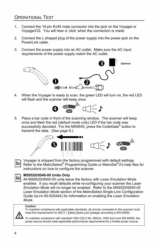
OPERATIONAL TEST
1. Connect the 10-pin RJ45 male connector into the jack on the Voyager orVoyagerCG. You will hear a ‘click’ when the connection is made.
2. Connect the L-shaped plug of the power supply into the power jack on thePowerLink cable.
3. Connect the power supply into an AC outlet. Make sure the AC inputrequirements of the power supply match the AC outlet.
4. When the Voyager is ready to scan, the green LED will turn on, the red LEDwill flash and the scanner will beep once.
5. Place a bar code in front of the scanning window. The scanner will beeponce and flash the red (default mode only) LED if the bar code wassuccessfully decoded. For the MS9540, press the CodeGate® button totransmit the data. (See page 8.)
Voyager is shipped from the factory programmed with default settings.Refer to the MetroSelect® Programming Guide or MetroSet®2’s help files forinstructions on how to configure the scanner.
MS9520/9540-00 Units OnlyAll MS9520/9540-00 units leave the factory with Laser Emulation Modeenabled. If you recall defaults while re-configuring your scanner the LaserEmulation Mode will no longer be enabled. Refer to the MS9520/9540-00Laser Emulation Mode section of the MetroSelect Single-Line ConfigurationGuide (MLPN 00-02544A) for information on enabling the Laser EmulationMode.
Caution:To maintain compliance with applicable standards, all circuits connected to the scanner mustmeet the requirements for SELV ( Safety Extra Low Voltage) according to EN 60950.
To maintain compliance with standard CSA C22.2 No. 950/UL 1950 and norm EN 60950, thepower source should meet applicable performance requirements for a limited power source.
Optional

5
INSTALLING THE SCANNER TO THE HOST SYSTEM
MS9520-00/9/11/14/41 AND MS9540-00/9/11/14/41
1. Turn off the host system.
2. Connect the 10-pin RJ45 maleconnector into the jack on theVoyager or VoyagerCG. You willhear a ‘click’ when the connectionis made.
If the scanner is receivingpower from the hostsystem, skip to step #5.
3. Connect the L-shaped plug of thepower supply into the power jackon the PowerLink cable.
4. Make sure the AC inputrequirements of the power supplymatch the AC outlet. Connect thepower supply into an AC outlet.The outlet should be near theequipment and easily accessible.
5. Connect the PowerLink cable tothe proper port on the hostsystem.
6. Turn on the host system.
Plugging the scanner into a port on the host system does not guaranteethat scanned information will be communicated properly to the hostsystem. The scanner is shipped from the factory programmed with defaultsettings. Please refer to the MetroSelect® Programming Guide(MLPN 00-02544) or MetroSet®2’s help files for instructions on changing thescanner’s configuration. In addition, please check that the scanner andhost system are using the same communication protocol.
All MS9520-00/MS9540-00 scanners leave the factory with the LaserEmulation Mode enabled. If you recall defaults while re-configuring yourscanner the Laser Emulation Mode will no longer be enabled. Refer to theMS9520/9540-00 Laser Emulation Mode section of the MetroSelectSingle-Line Configuration Guide (MLPN 00-02544A) for information onenabling the Laser Emulation Mode.Caution:To maintain compliance with applicable standards, all circuits connected to the scanner mustmeet the requirements for SELV (Safety Extra Low Voltage) according to EN 60950.
To maintain compliance with standard CSA C22.2 No. 950/UL 1950 and norm EN 60950, thepower source should meet applicable performance requirements for a limited power source.

6
INSTALLING THE SCANNER TO THE HOST SYSTEM
KEYBOARD WEDGE MS9520-47 AND MS9540-47
1. Turn off the PC.
2. Connect the 10-pin RJ45 male connectorinto the jack on the Voyager or theVoyagerCG. You will hear a ‘click’ whenthe connection is made.
3. Connect the L-shaped plug of the powersupply into the power jack on thePowerLink cable.
If the scanner is receivingpower from the host system,skip to step #5.
4. Make sure the AC input requirements ofthe power supply match the AC outlet.Connect the power supply into an ACoutlet. The outlet should be near theequipment and easily accessible.
5. Disconnect the keyboard from the PC.
6. The PowerLink cable is terminated with a5-pin DIN female connector on one end,and a 6-pin mini DIN male on the other.Metrologic will supply an adapter cablewith a 5-pin DIN male connector on oneend and a 6-pin mini DIN femaleconnector on the other. According to thetermination required, connect the appropriate end of the adapter cable to thePowerLink cable, leaving the necessary termination exposed for connectingto the keyboard and the keyboard port on the PC.
7. Connect to the PowerLink cable to the keyboard and the keyboard port onthe PC.
8. Power up the PC.
Powering the MS9520-47/MS9540-47 directly from the computer can sometimescause interference with the operation of the scanner or the computer. Not allcomputers supply the same current through the keyboard port, explaining why ascanner would work on one computer and not another. Contact a MetrologicCustomer Service Representative if you require an external power supply.
Caution:To maintain compliance with applicable standards, all circuits connected to the scanner mustmeet the requirements for SELV (Safety Extra Low Voltage) according to EN 60950. To maintain compliance with standard CSA C22.2 No. 950/UL 1950 and norm EN 60950, thepower source should meet applicable performance requirements for a limited power source.

7
INSTALLING THE SCANNER TO THE HOST SYSTEM
STAND ALONE KEYBOARD
1. Turn off the host system.
2. Connect the 10-pin RJ45 maleconnector into the jack on theVoyager or VoyagerCG. Youwill hear a ‘click’ when theconnection is made.
If the scanner isreceiving power fromthe host system, skip tostep #5.
3. Connect the L-shaped plug ofthe power supply into the powerjack on the PowerLink cable.
4. Make sure the AC inputrequirements of the powersupply match the AC outlet.Connect the power supply intoan AC outlet. The outlet shouldbe near the equipment andeasily accessible.
5. Connect the PowerLink cable tothe keyboard port on the hostsystem.
6. Turn on the host system.
Powering the MS9520-47/MS9540-47 directly from the computer cansometimes cause interference with the operation of the scanner or thecomputer. Not all computers supply the same current through thekeyboard port, explaining why a scanner would work on one computer andnot another. Contact a Metrologic Customer Service Representative if yourequire an external power supply.
Caution:To maintain compliance with applicable standards, all circuits connected to the scanner mustmeet the requirements for SELV (Safety Extra Low Voltage) according to EN 60950. To maintain compliance with standard CSA C22.2 No. 950/UL 1950 and norm EN 60950, thepower source should meet applicable performance requirements for a limited power source.

8
INSTALLING THE SCANNER TO THE HOST SYSTEM
INSTALLATION NOTES FOR USB INTERFACE
Metrologic’s MX009 USB cable is a device that converts serial RS232 formatteddata to either USB Keyboard or USB Point-of Sale communication protocol.
Please refer to the MX009 USB Converter Cable Programming Guide(MLPN 00-02574A) supplied with your MX009 cable for detailed installation andprogramming guidelines.
DISCONNECTING THE POWERLINK CABLE FROM THE SCANNER
Before removing the cable from the scanner, Metrologic recommends that thepower on the host system is off and the power supply has been disconnectedfrom the PowerLink cable.
1. Locate the small ‘pin-hole’ on the top of the unit near the bottom of theVoyager logo.
2. Bend an ordinary paperclip into the shape shown above.
3. Insert the paperclip (or other small metallic pin) into the small ‘pin-hole’.
4. You will here a faint ‘click’. Pull gently on the strain-relief of the PowerLinkcable and it will slide out of the scanner.
&

9
HOW TO USE CODEGATE® –MS9540 SERIES ONLY
TWO MODES OF OPERATION
• Auto-trigger while in the stand
• Bar code is automatically decoded andtransmitted
• CodeGate activates when removed fromthe stand
• Bar code data is transmitted when theCodeGate button is pressed
• Auto triggeractivates thelaser
• Place thelaser line onthe bar code
• Press theCodeGatebutton totransmit thedata
1
2
3

10
STAND KITS
Free Standing Kits #46-46128
Contains:a. Stand (MLPN 36-00454) ................................ Qty 1b. Apron (MLPN 50-50440) ................................ Qty 1c. Screw, M3 x 6 mm (MLPN 18-18670)............ Qty 2d. Washer, #5 x .5 OD (MLPN 18-18671) .......... Qty 2e. Stand Anchor (MLPN 50-50449).................... Qty 1f. M3 x 20 mm Set Screw (MLPN 18-18672) .... Qty 1
Optional Hard Mount Accessory Kit #46-46351
This kit, used in conjunction with the stand kit(#46-46128), can be used to bolt/hard mount the MS9500 to the countertop.
Contains:a. Screw, #8 Round Head (MLPN 18-18057) .... Qty 4b. Base (MLPN 36-36080) ................................. Qty 1
Optional Wall Mount Hanger AccessoryKit #46-46433
Contains:a. Screw #8 Round Head (MLPN 18-18057) ..... Qty.2b. Wall Mount Hanger (MLPN 18-18057)........... Qty.1
Optional Wall Mount HangerKit #46-46508
Contains:a. Wall Mount Hanger ( MLPN 36-00611 ) ....... Qty. 1b. Wall Mount Base (MLPN 36-00812) ........... Qty. 1c. 4.8 x 13 mm, Self Tapping Screw ............. Qty. 2
(MLPN 18-18233)d. Double-Sided Adhesive Tape ..................... Qty. 1
(MLPN 36-00821)e. #8 Wood Screw (MLPN 18-18057) .............. Qty. 2
a.
b..
e.
d.
a.
b.
f.
c.

11
ASSEMBLING THE STANDS
There are 2 options for assembling the stand. The first option allows the stand tobe self-supporting and moved freely or placed anywhere on the countertop. Thesecond option is used if the stand will be bolted/hard-mounted to the countertop.
Stand Option 1: Self-supportedFor use with kit #46-46128
Step 1
Slide the apron (MLPN 50-50440)over the stand (MLPN 36-00454).
Step 2
Position the stand so it sits underthe tab on the apron. Then securethe apron to the stand using theM3 x 6 mm screws(MLPN 18-18670) and the #5washers (MLPN 18-18671) provided.
Stand Option 2: Hard-mounted to countertopFor use with kit #46-46351
Step 1
Drill four #39 holes in the countertop.
Step 2
Secure the base (MLPN 36-36080)to the countertop with the four#8 wood screws (MLPN 18-18057) provided.
Continued on next page
Stand
Apron
ApronStand
M3 x 6 mmScrew
#5 WasherTab
Base
#8 WoodScrew
2.00 in
2.00 in

12
ASSEMBLING THE STAND (CONTINUED)
Stand Option 2: Hard-mounted to countertop (continued)For use with kits #46-46128, #46-46351 andMS951 Stand Replacements
Step 3
Screw the stand anchor (MLPN 50-50449)onto the base assembly until it sits flush.
Step 4
Remove the logo plate on the stand bygently using an exacto knife to releasethe plate hook.
Step 5
Position the stand over the baseassembly.
Step 6
Secure the stand to the base assemblyby installing and tightening the M3 setscrew (MLPN 18-18672) under the logoplate as shown.
Step 7
Snap the logo plate back into place.
Anchor fromKit #46-46128
Base Assembly fromKit #46-46351 or
MS951 Stand Base

13
ASSEMBLING THE STAND (CONT.)
Wall Mount, Option 1:
For Kit #46-46433 orKit #46-46508
Step 1:Drill two #39 pilot holes 3.00” apart.
Step 2:Attach the Wall Mount Hanger to the wallwith the two #8 wood screws provided.
Wall Mount, Option 2:
Kit #46-46508
Step 1:Attach the Wall Mount Base to the WallMount Hanger with the two 4.8 x 13 mmself-tapping screws.
Step 2:Remove one side of the protectivebacking from the double-sided adhesivetape.
Step 3:Attach the tape to the back of the WallMount Hanger as shown.
Step 4:Remove the protective backing from thedouble-sided adhesive tape and applyhook to the wall.

14
SCANNER PARTS
* This feature is not available on the MS9520
MS9500 Top View
MS9500 Side View
Red LED
Yellow LED*
CodeGate Button*
Output Window
Cable Connection
Green LED
15
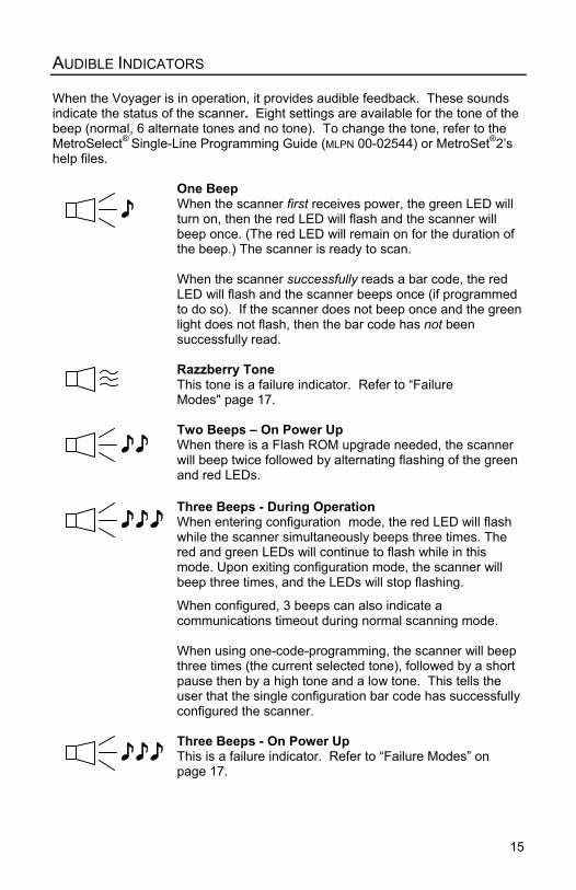
AUDIBLE INDICATORS
When the Voyager is in operation, it provides audible feedback. These soundsindicate the status of the scanner. Eight settings are available for the tone of thebeep (normal, 6 alternate tones and no tone). To change the tone, refer to theMetroSelect® Single-Line Programming Guide (MLPN 00-02544) or MetroSet®2’shelp files.
One BeepWhen the scanner first receives power, the green LED willturn on, then the red LED will flash and the scanner willbeep once. (The red LED will remain on for the duration ofthe beep.) The scanner is ready to scan.
When the scanner successfully reads a bar code, the redLED will flash and the scanner beeps once (if programmedto do so). If the scanner does not beep once and the greenlight does not flash, then the bar code has not beensuccessfully read.
Razzberry ToneThis tone is a failure indicator. Refer to “FailureModes" page 17.
Two Beeps – On Power UpWhen there is a Flash ROM upgrade needed, the scannerwill beep twice followed by alternating flashing of the greenand red LEDs.
Three Beeps - During OperationWhen entering configuration mode, the red LED will flashwhile the scanner simultaneously beeps three times. Thered and green LEDs will continue to flash while in thismode. Upon exiting configuration mode, the scanner willbeep three times, and the LEDs will stop flashing.
When configured, 3 beeps can also indicate acommunications timeout during normal scanning mode.
When using one-code-programming, the scanner will beepthree times (the current selected tone), followed by a shortpause then by a high tone and a low tone. This tells theuser that the single configuration bar code has successfullyconfigured the scanner.
Three Beeps - On Power UpThis is a failure indicator. Refer to “Failure Modes” onpage 17.

16
VISUAL INDICATORS
The MS9540 has three LED indicators (green, red and yellow) located on thehead of the scanner. The MS9520 has two LED indicators (green and red)located on the head of the scanner. When the scanner is on, the flashing orstationary activity of the LEDs indicates the status of the current scan and thescanner.
Green, Red & Yellow (MS9540’s Only) LEDs are offThe LEDs will not be illuminated if the scanner is notreceiving power from the host or transformer.
The scanner is stand-by mode, and CodeGate® is enabled.Present a bar code to the scanner and the green LED willturn on when the laser turns on.
Steady Yellow (MS9540’s Only)The CodeGate button is not active. If a bar code is in thescan field, the laser will turn on. The bar code will bedecoded and transmitted to the host automatically.
Steady GreenWhen the laser is active, the green LED is illuminated. Thegreen LED will remain illuminated until the laser isdeactivated. (Default Mode Only)
Steady Green and Single Red FlashWhen the scanner successfully reads a bar code, the redLED will flash and the scanner will beep once. If the red LEDdoes not flash or the scanner does not beep once, then thebar code has not been successfully read.(Default Mode Only)
Steady Green and Steady RedAfter a successful scan, the scanner transmits the data tothe host device. Some communication modes require thatthe host inform the scanner when data is ready to bereceived. If the host is not ready to accept the information,the scanner’s red LED will remain on until the data can betransmitted.

17
VISUAL INDICATORS (CONTINUED)
Alternating Flashing of Green and RedThis indicates the scanner is program mode. A razzberrytone indicates that an invalid bar code has been scannedwhile in this mode.
The scanner needs to have a Flash ROM upgrade if thealternating flashing of the red and green LEDs occurs duringstartup and is accompanied by three beeps.
Steady Red, Green offThis indicates the scanner may be waiting forcommunication from the host.

18
FAILURE MODES
Flashing Green and one Razzberry ToneThis indicates the scanner has experienced a laser sub-system failure. Return the unit for repair to an authorizedservice center.
Flashing Red and Green with Two Razzberry TonesThis indicates the scanner has experienced a scanningmechanism failure. Return the unit for repair to anauthorized service center.
Continuous Razzberry Tone with all LEDs offIf, upon power, the scanner emits a continuous razzberrytone, then the scanner has an experienced an electronicfailure. Return the unit for repair to an authorized servicecenter.
Three Beeps – on power upIf the scanner beeps 3 times on power up then the non-volatile memory (NovRAM) that holds the scannerconfiguration has failed. If the scanner does not respondafter reprogramming, return the scanner for repair to anauthorized service center.

19
PROGRAMMING MODES
The MS9500 Voyager has 3 modes of programming.
Bar CodesVoyager or Voyager CG can be configured by scanning the bar codeslocated in the MetroSelect® Single-Line Programming Guide (MLPN 00-02544). Please refer to this guide for instructions. This manual can bedownloaded for FREE from Metrologic’s website (www.metrologic.com).
MetroSet®2This user-friendly Windows-based configuration program allows you tosimply ‘point-and-click’ at the desired scanner options. This program can bedownloaded for FREE from Metrologic’ website (www.metrologic.com), orset-up disks can be ordered by calling 1-800-ID-METRO.
Serial ProgrammingThis mode of programming is ideal for OEM applications. This mode givesthe end-user the ability to send a series of commands using the serial port ofthe host system. The commands are equivalent to the numerical values ofthe bar codes located in the MetroSelect Single-Line Programming Guide(MLPN 00-02544).
How does Serial Programming work?
1. Each command sent to the scanner is the ASCII representation of eachnumeral in the configuration bar code. The entire numeric string is framedwith an ASCII [stx] and an ASCII [etx].
EXAMPLE #1:Command for Disabling CodabarCommand = [stx]100104[etx]String Sent to Scanner = 02h 31h 30h 30h 31h 30h 34h 03h(All values are hexadecimal).
2. If the command sent to the scanner is valid, the scanner will respond with an[ack].
3. If the command sent to the scanner in invalid, the scanner will respond witha [nak].
NOTE: If this occurs, the end-user must start over at the very beginning ofthe configuration sequence. Simply re-transmitting the invalidcommand will not work, you must start over.

20
PROGRAMMING MODES (CONTINUED)
4. During programming, the motor and laser turn off. YOU CANNOT SCAN ABAR CODE WHILE IN SERIAL PROGRAM MODE.
5. There is a 20 second window between commands. If a 20 second timeoutoccurs, the scanner will send a [nak] and you must start over.
6. To enter serial program mode, send the following command[stx]999999[etx].
7. To exit serial program mode, send the following command [stx]999999[etx],the scanner will respond with an [ack] followed by 3 beeps.
8. This mode uses the current Baud Rate, Parity, Stop Bits and Data Bitssettings that are configured in the scanner. The default settings of thescanner are 9600, Space, 2, 7 respectively. If a command is sent to thescanner to change any of these settings, the change will NOT take effectuntil after serial program mode is exited.
EXAMPLE #2:
The following example will set the scanner to the factory default settings,Disable Scanning of Code 128 bar codes, change the beeper tone, and adda “G” as a programmable prefix.
HOST SCANNERFEATURE COMMAND ASCII REPRESENTATION RESPONSEEnter Program Mode [stx]999999[etx] 02h 39h 39h 39h 39h 39h 39h 03h [ack] or 06hLoad Defaults [stx]999998[etx] 02h 39h 39h 39h 39h 39h 38h 03h [ack] or 06hDisable Code 128 [stx]100113[etx] 02h 31h 30h 30h 31h 31h 33h 03h [ack] or 06hAlternate Tone 1 [stx]318565[etx] 02h 33h 31h 38h 35h 36h 35h 03h [ack] or 06hProg. Prefix #1 [stx]903500[etx] 02h 39h 30h 33h 35h 30h 30h 03h [ack] or 06hCode Byte 0 [stx]0[etx] 02h 30h 03h [ack] or 06hCode Byte 7 [stx]7[etx] 02h 37h 03h [ack] or 06hCode Byte 1 [stx]1[etx] 02h 31h 03h [ack] or 06hExit Program Mode [stx]999999[etx] 02h 39h 39h 39h 39h 39h 39h 03h [ack] or 06hThe scanner will beep three times!
The commands sent to the scanner do not include the small superscripted‘3’ that you see in front of each bar code string in the MetroSelect manual.THE ‘3’ SHOULD NOT BE SENT, IT IS A CODE TYPE DESIGNATIONONLY!
As you will note for commands requiring additional bar codes to be scanned(such as prefixes, suffixes, timeouts, etc.), simply send the code bytes in thesame order that you would normally scan the bar codes.

21
PROGRAMMING MODES (CONTINUED)
EXAMPLE #3:
The following example shows the events that occur when an invalid bar codeis sent. This sample will load the factory default settings and then set thebaud rate to 19200.
HOST SCANNERFEATURE COMMAND ASCII REPRESENTATION RESPONSE
Enter Program Mode [stx]999999[etx] 02h 39h 39h 39h 39h 39h 39h 03h [ack] or 06hLoad Defaults [stx]99999:[etx] 02h 39h 39h 39h 39h 39h 3Ah 03h [nak] or 15hInvalid command was sent, you must start over!Enter Program Mode [stx]999999[etx] 02h 39h 39h 39h 39h 39h 39h 03h [ack] or 06hLoad Defaults [stx]999998[etx] 02h 39h 39h 39h 39h 39h 39h 03h [ack] or 06h19200 Baud Rate [stx]415870[etx] 02h 34h 31h 35h 38h 37h 30h 03h [ack] or 06hExit Program Mode [stx]999999[etx] 02h 39h 39h 39h 39h 39h 39h 03h [ack] or 06hThe scanner will beep three times!
This example illustrates two important points.
First, if an invalid command is sent from the host, the scanner responds witha [nak] and the end-user must start over from the beginning.
Second, if a command is sent to change the Baud Rate, the new baud ratedoes not take effect until after the end-user exits program mode.
ABBREVIATED ASCII TABLE
Character Hex Value Decimal Value[STX] 02h 2[ETX] 03h 3[ACK] 06h 6[NAK] 15h 21
0 30h 481 31h 492 32h 503 33h 514 34h 525 35h 536 36h 547 37h 558 38h 569 39h 57

22
UPGRADING THE FLASH ROM FIRMWARE
The Meteor program is a functional component of Metrologic’s new line of Flash-based scanners. This program allows the user of a Metrologic scanner to quicklyupgrade to a new or custom version of software. It requires the use of a personalcomputer running under Windows 95 or greater and the use of a communicationport. The user merely connects the scanner to a communications port of the PC,launches the Meteor program, and blasts off to new software upgrades.
Each MS9500, regardless of the version number or communication protocol, canbe upgraded. In other words, all RS232 (-41), keyboard wedge (-47), light pen(-41), laser emulation (-00), OCIA (-9) and IBM 468X/469X (-11) units can beupgraded. To upgrade all units, a power supply and PowerLink cable(MLPN 54-54012) are required.
The upgrades and custom software versions will be supplied by Metrologic infiles called Motorola S-record files. These files contain all the information neededto upgrade the scanner. Simply add this file to the working directory or retrievefrom its current location.
The program guides the user with its simplistic one click approach. The usermust first select the file; once selected and verified, the file is ready to be used inthe upgrade. Press the button to upgrade the scanner, the unit will go into a“flash mode” – both the green and red LEDs will be on. The user can follow theprogress of the upgrade by watching the screen for details. When the upgrade iscomplete, the scanner will respond with its normal one beep on power up. If twobeeps occur, the scanner did not upgrade properly. (Contact Metrologic foradditional details).

23
LABELS
Each scanner has a label on the back of the unit. This label has the modelnumber, date of manufacture, serial number, CE and caution information. Thefollowing is an example of this label:
MAINTENANCE
Smudges and dirt can interfere with the proper scanning of a bar code.Therefore, the output window will need occasional cleaning.
1. Spray glass cleaner onto lint free, non-abrasive cleaning cloth.2. Gently wipe the scanner window.
Patent Information-See ManualFCC and ICES-003 Information-See Manual
Warranty VOID if case opened.Contains no user serviceable components.Complies with 21CFR 1040.10 & 1040.11
NACH EN60825-1:1994/A11:19965V
AVOID EXPOSURE –Laser light is emitted from this aperture
EVITER TOUTE EXPOSITION-Lumiere laser emis par cette overture

24
DEPTH OF FIELD
Minimum Bar Code Element WidthA B C D E F G H J K
mm .13 .15 - - .19 - .25 .33 .53 -
mils 5.2 5.7 - - 7.5 - 10 13 21 -

25
IR ACTIVATION

26
APPLICATIONS AND PROTOCOLS
The model number on each scanner includes the scanner number and factorydefault communications protocol.
Scanner VersionIdentifier Communication Protocol(s)
MS9520MS9540 41 RS-232/Light Pen Emulation
MS9520MS9540 47 Keyboard Wedge, Stand-Alone Keyboard and
RS-232 Transmit/Receive
MS9520MS9540 9 OCIA and RS-232 Transmit/Receive
MS9520MS9540 11 IBM 468X/469X, RS232-TXD, RXD, RTS, CTS
MS9520MS9540 00 Laser Emulation and
RS-232 Transmit/Receive
MS9520MS9540 14 RS232-TXD, RXD, RTS, CTS, DTR, DSR
The MS9500 Series Hand-Held Laser Scanner with built-in PC Keyboard WedgeInterface is designed to be used for Keyboard emulation only. Many RS-232programmable functions available in other Metrologic scanners are also availableas keyboard wedge functions.
The following are the most important selectable options specific to the keyboardwedge.
Keyboard Type
• **AT (includes IBM® PS2 models 50, 55, 60, 80)• XT• IBM PS2 (includes models 30, 70, 8556)
Keyboard Country Type
• **USA • German • Spanish• Belgium • Italian • Swiss• French • Japanese • United Kingdom
**Default setting. Refer to pages 30-34 for default settings. Refer to theMetroSelect® Single-Line Programming Guide (MLPN 00-02544) or MetroSet®2’shelp files for information on how to change the default settings.

27
TROUBLESHOOTING GUIDE
The following guide is for reference purposes only. Contact a Metrologicrepresentative at 1-800-ID-Metro or 1-800-436-3876 to preserve the limitedwarranty terms.
All InterfacesMS9500 Series Troubleshooting Guide
Symptoms Possible Causes Solution
No LEDs, beepor laser
No power is beingsupplied to thescanner
Check transformer, outlet andpower strip. Make sure the cableis plugged into the scanner.
No LEDs, beep,or laser
No power is beingsupplied to thescanner from host
Some host systems cannot supplyenough current to power Voyager.A power supply may be needed.
2 Beeps withalternatelyflashing LEDson Power up
Possible ROM failure Flash ROM Upgrade Required
3 Beeps onpower up
Non-volatile RAMfailure
Contact a MetrologicRepresentative, if the unit will nothold the programmedconfiguration.
Continuous razztone on powerup
RAM or ROM failureContact a MetrologicRepresentative, if the unit will notfunction.
Razz tone andgreen LED flashat power up
VLD failure Contact a MetrologicRepresentative
Razz tone, redand green LEDsflash at powerup
Scanning mechanismfailure
Contact a MetrologicRepresentative
Unit scans,Communicatesand beeps twice
Same symbol timeoutset too short
Adjust same symbol timeout for alonger time.
The unit powersup, but does notscan/or beep
Beeper disabled. Notone selected Enable beeper. Select tone.

28
TROUBLESHOOTING GUIDE (CONTINUED)
Symptoms Possible Causes Solution
The unit powersup, but does notscan and/orbeep
Scanning a particularsymbology that is notenabled
UPC/EAN, Code 39, interleaved 2of 5, Code 93, Code 128 andCodabar are enabled by default.Verify that the type of bar codebeing read has been selected.
The unit powersup, but does notscan and/orbeep
The scanner hasbeen programmed fora character lengthlock, or a minimumlength and bar codebeing scanned doesnot satisfy theprogrammed criteria
Verify that the bar code that isbeing scanned falls into thecriteria (Typical of Non-UPC/EANcodes) The scanner defaults to aminimum of 3 character bar code.
The unit scansa bar code, butlocks up afterthe first scanred LED stayson
The scanner isconfigured to supportsome form of hosthandshaking but isnot receiving thesignal
If the scanner is setup to supportACK/NAK, RTS/CTS, XON/XOFFor D/E, verify that the host cableand host are supporting thehandshaking properly.
The unit scans,but the datatransmitted tothe host isincorrect
The scanner’s dataformat does notmatch the hostsystem requirements
Verify that the scanner’s dataformat matches that required bythe host. Most sure that thescanner is connected to theproper host port.
Scanner beepsat some barcodes and NOTfor others of thesame bar codesymbology
The print quality ofthe bar code issuspect
Check print mode. The type ofprinter could be the problem.Change print settings. i.e. changeto econo mode or high speed.
Scanner beepsat some barcodes and NOTfor others of thesame bar codesymbology
The aspect ratio ofthe bar code is out oftolerance
Check print mode. The type ofprinter could be the problem.Change print settings. i.e. changeto econo mode or high speed.

29
TROUBLESHOOTING GUIDE (CONTINUED)
Symptoms Possible Causes SolutionScanner beepsat some barcodes and NOTfor others of thesame bar codesymbology
The bar code mayhave been printedincorrectly
Check if it is a checkdigit/character/or border problem.
Scanner beepsat some barcodes and NOTfor others of thesame bar codesymbology
The scanner is notconfigured correctlyfor this type of barcode
Check if check digits are setproperly.
Scanner beepsat some barcodes and NOTfor others of thesame bar codesymbology
The minimum symbollength setting doesnot work with the barcode
Check if the correct minimumsymbol length is set.
The unit scansthe bar code butthere is no data
Configuration is notcorrect
Make sure the scanner isconfigured for the appropriatemode.
The unit scansbut the data isnot correct
Configuration iscorrect
Make sure that the proper PC typeAT, PS2 or XT is selected. Verifycorrect country code and dataformatting are selected. Adjustinter-character delay symptom.
The unit istransmittingeach charactertwice
Configuration is notcorrect
Increase interscan code delaysetting. Adjust whether the F0break is transmitted. It may benecessary to try this in bothsettings.

30
TROUBLESHOOTING GUIDE (CONTINUED)
Symptoms Possible Causes Solution
Alphacharacters showas lower case
Computer is in CapsLock mode
Enable Caps Lock detect settingof the scanner to detect whetherthe PC is operating in Caps Lock.
Everythingworks except fora couple ofcharacters
These charactersmay not be supportedby that country’s keylook up table
Try operating the scanner in Altmode.
Power-up OKand scans OKbut does notcommunicateproperly to thehost
Com port at the hostis not working orconfigured properly
Check to make sure that the baudrate and parity of the scanner andthe communication port matchand the program is looking for“RS-232” data.
Power-up OKand scans OKbut does notcommunicateproperly to thehost
Cable not connectedto the proper comport
Check to make sure that the baudrate and parity of the scanner andthe communication port matchand the program is looking for“RS-232” data.
Power-up OKand scans OKbut does notcommunicateproperly to thehost
Cable not connectedto the proper comport
Check to make sure that the baudrate and parity of the scanner andthe communication port matchand the program is looking for“RS-232” data.
The host isreceiving databut the datadoes not lookcorrect
The scanner and hostmay not beconfigured for thesame interfaceparameters
Check that the scanner and thehost are configured for the sameinterface parameters
Characters arebeing dropped
Inter-character delayneeds to be added tothe transmitted output
Add some inter-character delay tothe transmitted output by usingthe MetroSelect Single-LineProgramming Guide MLPN 00-02544.

31
RS-232 DEMONSTRATION PROGRAM
If an RS-232 scanner is not communicating with your IBM compatible PC, key inthe following BASIC program to test that the communication port and scanner areworking.
This program is for demonstration purposes only. It is only intended to prove thatcabling is correct, the com port is working, and the scanner is working. If the barcode data displays on the screen while using this program, it only demonstratesthat the hardware interface and scanner are working. At this point, investigatewhether the application software and the scanner configuration match.
If the application does not support RS-232 scanners, a software wedge programthat will take RS-232 data and place it into a keyboard buffer may be needed.This program tells the PC to ignore RTS-CTS, Data Set Ready (DSR) and DataCarrier Detect (DCD) signals. If the demonstration program works and yours stilldoes not, jumper RTS to CTS and Data Terminal Reading (DTR) to DCD andDSR on the back of your PC.
10 CLS20 ON ERROR GOTO 10030 OPEN “COM1:9600,S,7,1,CSO,DSO,CD0,LF” AS#135 PRINT “SCAN A FEW BAR CODES”40 LINE INPUT #1, BARCODE$50 PRINT BARCODE$60 K$ = INKEY$: IF K$ = CHR$(27) THEN GOTO 3276670 GOTO 40100 PRINT “ERROR NO.”; ERR ;“PRESS ANY KEY TO TERMINATE.”110 KK$ = INKEY$: IF K$ = “”THEN GOTO 11032766 CLOSE: SYSTEM32767 END

32
DESIGN SPECIFICATIONS
OPERATIONAL
Light Source: Visible Laser Diode 650 nm ± 10 nmLaser Power: Less than 1 mW (peak)
Depth of Scan Field: 0 mm – 203 mm (0” – 8”) for 0.330 mm (13 mil) bar code atdefault setting
Scan Speed: 72 scan lines per secondScan Pattern: Single scan line
Minimum Bar Width: 0.127 mm (5.0 mil)
InfraRed Activation: Long Range: 0 mm – 279 mm ± 51 mm (0” – 11” ± 2”)Short Range: 0 mm – 102 mm ± 25 mm (0” – 4” ± 1”)
Decode Capability: Autodiscriminates all standard bar codes for others call aMetrologic service representative
System Interfaces:RS232, PC Keyboard Wedge, Stand-Alone Keyboard,OCIA, IBM 468X/469X, Light Pen Emulation, LaserEmulation, RS232 with DSR
Print Contrast: 35% minimum reflectance differenceNumber Characters
Read:Up to 80 data characters(Maximum number will vary based on symbology & density)
Roll, Pitch, Yaw: 42°, 68°, 52°Beeper Operation: 7 tones or no beep
Indicators (LED) Default Settings:
Green = laser on, ready to scan; Red = good read;Yellow (MS9540 Only) = CodeGate button is inactive (on).CodeGate button is active (off)
MECHANICAL
Length: 198 mm (7.8”)Width: Handle - 45 mm (1.8”), Head - 78 mm (3.1”)Depth: 40 mm (1.6”)
Weight: 149 g (5.25 oz)ELECTRICAL
Input Voltage: 5VDC ± 0.25VPower: Operating = 0.825 W, Standby = 0.600 W
Current: Operating = 165 mA @ 5VDC, Standby = 120 mA @ 5VDCDC Transformers: Class 2; 5.2V @ 650 mA
Laser Class: CDRH: Class II; EN60825-1:1994/A11:1996 Class 1EMC: FCC Class B
ENVIRONMENTAL
Temperature: Operating = 0°C to 40° (32° to 104°F)Storage = -40°C to 60°C (-40°F to 140°F)
Humidity: 5% to 95% relative humidity, non-condensingLight Levels: Up to 4842 Lux (450 footcandles)
Shock: Designed to withstand 1.5 m (5’) dropsContaminants: Sealed to resist airborne particulate contaminants
Ventilation: None required

33
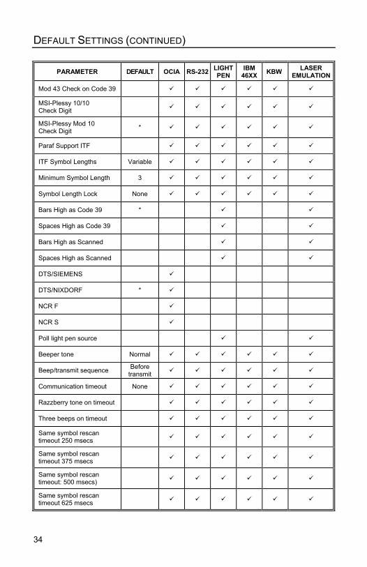
DEFAULT SETTINGS
Many functions of the scanner can be “programmed” – that is, enabled ordisabled. The scanner is shipped from the factory programmed to a set ofdefault conditions. The default parameter of the scanner has an asterisk (*) inthe charts on the following pages. If an asterisk is not in the default column thenthe default setting is OFF or DISABLED. Every communication does not supportevery parameter. If the communication supports a parameter listed in the chartson the following pages, a check mark will appear.
PARAMETER DEFAULT OCIA RS-232 LIGHTPEN
IBM46XX KBW LASER
EMULATION
Normal Scan Mode *
Continuous Scan Mode
Blinky Scan
Continuous Blinky Scan
Custom (one shot) Scan
Long-Range In-Stand *
Short-Range In-Stand
Long-Range Out-of-Stand *
Short-Range Out-of-Stand
CodeGate Active In-Stand
CodeGate Inactive In-Stand *
CodeGate ActiveOut-of Stand *
CodeGate InactiveOut-of Stand
UPC/EAN *
Code 128 *
Code 93 *
Codabar *
Interleaved 2 of 5 (ITF) *
MOD 10 check on ITF
Code 11
Code 39 *
Full ASCII Code 39
34
DEFAULT SETTINGS (CONTINUED)
PARAMETER DEFAULT OCIA RS-232 LIGHTPEN
IBM46XX KBW LASER
EMULATION
Mod 43 Check on Code 39
MSI-Plessy 10/10Check Digit
MSI-Plessy Mod 10Check Digit *
Paraf Support ITF
ITF Symbol Lengths Variable
Minimum Symbol Length 3
Symbol Length Lock None
Bars High as Code 39 *
Spaces High as Code 39
Bars High as Scanned
Spaces High as Scanned
DTS/SIEMENS
DTS/NIXDORF *
NCR F
NCR S
Poll light pen source
Beeper tone Normal
Beep/transmit sequence Beforetransmit
Communication timeout None
Razzberry tone on timeout
Three beeps on timeout
Same symbol rescantimeout 250 msecs
Same symbol rescantimeout 375 msecs
Same symbol rescantimeout: 500 msecs)
Same symbol rescantimeout 625 msecs

35
DEFAULT SETTINGS (CONTINUED)
PARAMETER DEFAULT OCIA RS-232 LIGHTPEN
IBM46XX KBW LASER
EMULATION
Same symbol rescantimeout 750 msecs
Same symbol rescantimeout 875 msecs *
Same symbol rescantimeout: 1000 msecs
No Same symbol timeout
Infinite Same symboltimeout
Inter-character delayProgram able in 1 msecsteps (max 255 msecs)
1 msecs10 msecs in KBW
Number of scan buffers(maximum) 4
Transmit UPC-A check digit *
Transmit UPC-E check digit
Expand UPC-E
Convert UPC-A to EAN-13
Transmit lead zero onUPC-ETransmit UPC-A numbersystem *
Transmit UPC-AManufacturer ID# *
Transmit UPC –A Item ID# *
Transmit CodabarStart/Stop Characters
CLSI Editing (Enable)
Transmit Mod 43 Checkdigit on Code 39
Transit Mod 10/ITF
Transmit MSI-Plessy
Parity Space
Baud Rate 9600
8 Data Bits
7 Data Bits *
Stop Bits 2

36
DEFAULT SETTINGS (CONTINUED)
PARAMETER DEFAULT OCIA RS-232 LIGHTPEN
IBM46XX KBW LASER
EMULATIONTransmit Sanyo IDCharacters
Nixdorf ID
LRC Enabled
UPC Prefix
UPC Suffix
Carriage Return *
Line Feed-Disabled bydefault in KBW *
Tab Prefix
Tab Suffix
“DE” Disable Command
“FL” Laser
Enable Command
DTR Handshaking support
RTS/CTS Handshaking
Character *
Message RTS/CTS
XON/XOFF Handshaking
ACK/NAK
Two Digit Supplements ascode 39
ascode 39
Five Digit Supplements ascode 39
ascode 39
Bookland ascode 39
ascode 39
977 (2 digit) SupplementalRequirement
Supplements are notRequired *
Two Digit Redundancy *
Five digit Redundancy

37
DEFAULT SETTINGS (CONTINUED)
PARAMETER DEFAULT OCIA RS-232 LIGHTPEN
IBM46XX KBW LASER
EMULATION
100 msec to FindSupplement Programmablein 100 msec steps(max 800 msec)
*
Coupon Code 128 ascode 39
ascode 39
† Programmable CodeLengths 7 avail
† Code Selects withprogrammable CodeLength Locks
3 avail
Programmable Prefixcharacters 10 avail
Suffix characters 10 avail
Prefixes for IndividualCode types
Editing
Inter Scan-Code delayprogrammable(100 µsec steps)
800 µsec
Function/control KeySupport
Minimum Element widthProgrammable in 5.6 µsecsteps
1 msec
† These options are mutually exclusive. One can not be used in conjunction with the other.

38
1 10
SCANNER AND CABLE TERMINATIONS
Scanner Pinout Connections
MS9520-41 & MS9540-41RS-232C and Light Pen Emulation
Pin Function1 Ground2 RS-232 Transmit Output3 RS-232 Receive Input4 RTS Output5 CTS Input6 DTR Input/LTPN Source7 Reserved8 LTPN Data9 +5VDC
The MS9520 and MS9540scanner interfaces terminate toa 10-pin modular jack. Theserial # label indicates theinterface enabled when thescanner is shipped from thefactory.
10 Shield Ground
MS9520-47 & MS9540-47 KeyboardWedge and Stand-Alone Keyboard
Pin Function1 Ground2 RS-232 Transmit Output3 RS-232 Receive Input4 PC Data5 PC Clock6 KB Clock7 PC +5V8 KB Data9 +5VDC10 Shield Ground
MS9520-11 & MS9540-11 IBM 468X/469X
Pin Function1 Ground2 RS-232 Transmit Output3 RS-232 Receive Input4 RTS Output5 CTS Input6 DTR Input7 IBM B-Transmit8 IBM A+ Receive9 +5VDC10 Shield Ground
Continued next page

39
1 10
SCANNER AND CABLE TERMINATIONS
MS9520-9 & MS9540-9 OCIA
Pin Function1 Ground2 RS232 Transmit Output3 RS232 Receive Input4 RDATA5 RDATA Return6 Clock In7 Clock Out8 Clock in Return/Clock out Rtrn9 +5VDC10 Shield Ground
MS9520-00 & MS9540-00
Pin Function1 Ground2 RS232 Transmit Output3 RS232 Receive Input4 Flip Sense/Start of Scan Output5 Proximity Detect/Trigger Emulation Output6 Scan/Laser Enable Input7 Reserved8 Data Out9 +5VDC10 Shield Ground
MS9520-14 & MS9540-14
Pin Function1 Ground2 RS-232 Transmit Output3 RS-232 Receive Input4 RTS Output5 CTS Input6 DTR Input7 Reserved8 DSR Out9 +5VDC10 Shield Ground

40
SCANNER AND CABLE TERMINATIONS (CONTINUED)
Cable Connector Configurations (Host End)
“Standard” PowerLink cable
9-pin D-type female connector to the PC
Pin Function1 Shield Ground2 RS-232 Transmit Output3 RS-232 Receive Input4 DTR Input/Light Pen Source5 Power/Signal Ground
6 Light Pen Data(DSR Out for -14 interfaces)
7 CTS Input8 RTS Output9 +5VDC
Stand Alone Keyboard Power Link Cable
Pin Function1 PC Data2 NC3 Power Ground4 +5VDC PC Power to KB5 PC Clock6 NC
9-Pin D-Type Connector
9 5
6 1
4
2 1
36 5
6-Pin Male Mini-DIN Connector

41
SCANNER AND CABLE TERMINATIONS (CONTINUED)
Cable Connector Configuration
The Keyboard Wedge PowerLink cable [MLPN 53-53002 or 54-54002] isterminated with a 5-pin DIN female connector on one end, and a 6-pin mini DINmale on the other.
Metrologic will supply an adapter cable with a 5-pin DIN male connector on oneend and a 6-pin mini DIN female connector on the other.
According to the termination required, connect the appropriate end of the adaptercable to the PowerLink cable, leaving the necessary termination exposed forconnecting to the keyboard and the keyboard port on the PC. The pinassignments are as follows:
PowerLink Cable Adapter Cable
5-pin Female DIN 5-pin Male DINPin Function Pin Function1 Keyboard Clock 1 PC Clock2 Keyboard Data 2 PC Data3 No Connect 3 No Connect4 Power Ground 4 Power Ground5 +5 Volts DC 5 +5 Volts DC
6-pin Male Mini-DIN 6-pin Female Mini-DINPin Function Pin Function1 PC Data 1 Keyboard Data2 No Connect 2 No Connect3 Power Ground 3 Power Ground4 +5 Volts DC 4 +5 Volts DC5 PC Clock 5 Keyboard Clock6 No Connect 6 No Connect
6-pin Mini DIN, Female5-Pin DIN, MaleAdapter Cable
3
1 2
45 6
2
35 4
1
42 1
36 5
6-Pin DIN, Male
2
14 5
3
5-Pin DIN, FemaleKeyboard WedgePowerLink Cable

42
LIMITED WARRANTY
The MS9500 series scanners are manufactured by Metrologic at its Blackwood, NewJersey, USA facility. The MS9500 series scanners have a five (5) year limited warrantyfrom the date of manufacture. Metrologic warrants and represents that all MS9500 seriesscanners are free of all defects in material, workmanship and design, and have beenproduced and labeled in compliance with all applicable US Federal, state and local laws,regulations and ordinances pertaining to their production and labeling.
This warranty is limited to repair, replacement of Product or refund of Product price at thesole discretion of Metrologic. Faulty equipment must be returned to the Metrologic facility inBlackwood, New Jersey, USA or Puchheim, Germany. To do this, contact Metrologic’sCustomer Service/Repair Department to obtain a Returned Material Authorization (RMA)number.
In the event that it is determined that the equipment failure is covered under thewarranty, Metrologic shall, as its sole option, repair the Product or replace the Productwith a functionally equivalent unit and return such repaired or replaced Product withoutcharge for service or return freight, whether distributor, dealer/reseller, or retailconsumer, or refund an amount equal to the original purchase price.
This limited warranty does not extend to any Product which, in the sole judgement ofMetrologic, has been subjected to abuse, misuse, neglect improper installation, oraccident, nor any damage due to use or misuse produced from integration of the Productinto any mechanical, electrical or computer system. The warranty is void if the case ofProduct is opened by anyone other than Metrologic’s repair department or authorizedrepair centers.
THIS LIMITED WARRANTY, EXCEPT AS TO TITLE, IS IN LIEU OF ALL OTHERWARRANTIES OR GUARANTEES, EITHER EXPRESS OR IMPLIED, ANDSPECIF ICALLY EXCLUDES, WITHOUT L IMITATION, WARRANTIES OFMERCHANTABILITY AND FITNESS FOR A PARTICULAR PURPOSE UNDER THEUNIFORM COMMERCIAL CODE, OR ARISING OUT OF CUSTOM OR CONDUCT.THE RIGHTS AND REMEDIES PROVIDED HEREIN ARE EXCLUSIVE AND IN LIEUOF ANY OTHER RIGHTS OR REMEDIES. IN NO EVENT SHALL METROLOGIC BELIABLE FOR ANY INDIRECT OR CONSEQUENTIAL DAMAGES, INCIDENTALDAMAGE, DAMAGES TO PERSON OR PROPERTY, OR EFFECT ON BUSINESS ORPROPERTY, OR OTHER DAMAGES OR EXPENSES DUE DIRECTLY ORINDIRECTLY TO THE PRODUCT, EXCEPT AS STATED IN THIS WARRANTY. IN NOEVENT SHALL ANY LIABILITY OF METROLOGIC EXCEED THE ACTUAL AMOUNTPAID TO METROLOGIC FOR THE PRODUCT. METROLOGIC RESERVES THERIGHT TO MAKE ANY CHANGES TO THE PRODUCT DESCRIBED HEREIN.
North America HeadquartersMetrologic Instruments, Inc. Customer Service: 1-800-ID-METRO90 Coles Road Tel: 856-228-8100Blackwood, NJ 08012-4683 Fax: 856-228-6673
Email: [email protected]: www.metrologic.com
GermanyMetrologic Instruments GmbH Tel: 49-89-89019-0Dornierstrasse 2 Fax: 49-89-89019-20082178 Puchheim b. Email: [email protected], Germany

43
NOTICES
NoticeThis equipment has been tested and found to comply with the limits for a Class B digital device,pursuant to Part 15 of the FCC rules. These limits are designed to provide reasonable protection againstharmful interference in a residential installation. This equipment generates, uses and can radiate radiofrequency and, if not installed and used in accordance with the instruction, may cause harmfulinterference to radio communications. However, there is no guarantee that interference will not occur ina particular installation. If this equipment does cause harmful interference to radio or televisionreception, which can be determined by turning the equipment off and on, the user is encouraged to try tocorrect the interference by one or more of the following measures:
• Reorient or relocate the receiving antenna• Increase the separation between the equipment and receiver• Connect the equipment into an outlet on a circuit different from that to which the receiver is connected• Consult the dealer or an experienced radio TV technician for help
Changes or modifications not expressly approved by the party responsible for compliance could void theuser’s authority to operate the equipment.
NoticeThis Class B digital apparatus complies with Canadian ICES-003.
RemarqueCet appareil numerique de la class B est conforme à la norme NMB-003 du Canada.
CautionUse of controls or adjustments or performance of procedures other than those specified herein may resultin hazardous laser light exposure. Under no circumstances should the customer attempt to service thelaser scanner. Never attempt to look at the laser beam, even if the scanner appears to be nonfunctional.Never open the scanner in an attempt to look into the device. Doing so could result in hazardous laserlight exposure. The use of optical instruments with the laser equipment will increase eye hazard.
AtenciónLa modificación de los procedimientos, o la utilización de controles o ajustes distintos de losespecificados aquí, pueden provocar una luz de láser peligrosa. Bajo ninguna circunstancia el usuariodeberá realizar el mantenimiento del láser del escáner. Ni intentar mirar al haz del láser incluso cuandoeste no esté operativo. Tampoco deberá abrir el escáner para examinar el aparato. El hacerlo puedeconllevar una exposición peligrosa a la luz de láser. El uso de instrumentos ópticos con el equipo láserpuede incrementar el riesgo para la vista.
AttentionL'emploi de commandes, réglages ou procédés autres que ceux décrits ici peut entraîner de gravesirradiations. Le client ne doit en aucun cas essayer d'entretenir lui-même le scanner ou le laser. Neregardez jamais directement le rayon laser, même si vous croyez que le scanner est inactif. N'ouvrezjamais le scanner pour regarder dans l'appareil. Ce faisant, vous vous exposez à une rayonnement laserqú êst hazardous. L'emploi d'appareils optiques avec cet équipement laser augmente le risqued'endommagement de la vision.
AchtungDie Verwendung anderer als der hier beschriebenen Steuerungen, Einstellungen oder Verfahren kanneine gefährliche Laserstrahlung hervorrufen. Der Kunde sollte unter keinen Umständen versuchen, denLaser-Scanner selbst zu warten. Sehen Sie niemals in den Laserstrahl, selbst wenn Sie glauben, daßder Scanner nicht aktiv ist. Öffnen Sie niemals den Scanner, um in das Gerät hineinzusehen. Wenn Siedies tun, können Sie sich einer gefährlichen Laserstrahlung aussetzen. Der Einsatz optischer Geräte mitdieser Laserausrüstung erhöht das Risiko einer Sehschädigung.
AttenzioneL’utilizzo di sistemi di controllo, di regolazioni o di procedimenti diversi da quelli descritti nel presenteManuale può provocare delle esposizioni a raggi laser rischiose. Il cliente non deve assolutamentetentare di riparare egli stesso lo scanner laser. Non guardate mai il raggio laser, anche se credete chelo scanner non sia attivo. Non aprite mai lo scanner per guardare dentro l’apparecchio. Facendolopotete esporVi ad una esposizione laser rischiosa. L’uso di apparecchi ottici, equipaggiati con raggilaser, aumenta il rischio di danni alla vista.

44
PATENTS
Patents
“Patent Information
This METROLOGIC product may be covered by one or more of the following USPatents:
US Patent No. 4,958,984; 5,081,342; 5,260,553; 5,340,971; 5,340,973;5,424,525; 5,468,951; 5,484,992; 5,525,789; 5,528,024; 5,591,953; 5,616,908;5,627,359; 5,661,292; 5,777,315; 5,789,730; 5,789,731; 5,811,780; 5,825,012;5,828,048; 5,883,375; 5,886,337; 5,895,907; 5,925,870; 5,925,871; 5,939,698;6,029,894; D408,532;
4,360,798; 4,369,361; 4,387,297; 4,460,120; 4,593,186; 4,607,156; 4,673,805;4,736,095; 4,758,717; 4,816,660; 4,845,350; 4,896,026; 4,923,281; 4,933,538;4,992,717; 5,015,833; 5,017,765; 5,059,779; 5,117,098; 5,124,539; 5,130,520;5,132,525; 5,140,144; 5,149,950; 5,180,904; 5,200,599; 5,229,591; 5,247,162;5,250,790; 5,250,791; 5,250,791; 5,250,792; 5,262,628; 5,280,162; 5,280,164;5,304,788; 5,321,246; 5,324,924; 5,396,053; 5,396,055; 5,408,081; 5,410,139;5,436,440; 5,449,891; 5,468,949; 5,479,000; 5,532,469; 5,545,889
No license right or sublicense is granted, either expressly or by implication,estoppel, or otherwise, under any METROLOGIC or third party intellectualproperty rights (whether or not such third party rights are licensed toMETROLOGIC), including any third party patent listed above, except for animplied license only for the normal intended use of the specific equipment,circuits, and devices represented by or contained in the METROLOGIC productsthat are physically transferred to the user, and only to the extent ofMETROLOGIC’s license rights and subject to any conditions, covenants andrestrictions therein.”
Other worldwide patents pending.

45
INDEX
A
AC Input/Outlet......................5, 6, 7accessories ...................................2accessories ...................................2adapter ..........................................2approvals.....................................23audible.........................................15autodiscriminates ........................32
B
bar code ......1, 4, 15, 16, 17, 19-21, 23, 24, 28, 29, 32
beep ..........4, 15, 16, 20-22, 27, 28, 32, 34
C
Cable.......................2, 3, 30, 40, 41communication .......5, 16, 17, 22,
30, 33detachable.............................1, 8pin assignments ......................41powerLink .......1, 2, 4, 5, 7, 8, 22,
40, 41caution.........................4, 5, 6, 7, 23CDRH..........................................32CE ...............................................43codeGate.................1, 9, 16, 32, 33compliance ............4, 5, 6, 7, 42, 43configuration.........1, 15, 19, 27, 31,
40, 41connector.......................................2current .....................6, 7, 15, 27, 32customer Service................. ii, 3, 42
D
decode Capability........................32default Settings........4, 5, 20, 21, 26depth of Field.........................24, 25detachable.....................................3disclaimer ....................................42
E
electrical ......................................32
F
failure Indicator(s) ....................... 15failure Modes ........................ 15, 18
G
green LED................... 4, 15, 16, 27
H
host ............. 1-3, 5, 7, 8, 16, 17, 19,21, 27, 28, 30
I
indicatorsaudible .................................... 15LED....... 4, 14, 15, 16, 27, 28, 32
input Voltage ............................... 32installation ............................. 42, 43interfaces ........................ 27, 32, 38
K
keyboard Wedge....................... 1, 2
L
labels .......................................... 23light Levels .................................. 32light Pen....... 1, 2, 22, 26, 33, 34-37light Source ................................. 32
M
maintenance ............................... 23meteor......................................... 22
N
notices......................................... 43
O
OCIA ......................................... 1, 2operation ..................................... 15output window............................. 14

46
INDEX
P
parts ........................................2, 14PC . 5, 22, 26, 29, 30, 32, 38, 40, 41pin Assignments ..........................41port ................................................6power Supply.............4, 6, 8, 22, 27powerLink ..................................5, 7programming ... 4, 15, 19, 20, 26, 30programming guide .......................2
R
razzberry Tone ..........15, 17, 18, 34red LED ................. 4, 15, 16, 22, 28repair .....................................18, 42RMA ............................................42RS-232 .........1, 2, 26, 30, 31, 33-40
S
SELV .................................4, 5, 6, 7service .....................................3, 42specifications...............................32stand..............................................2system interfaces ........................32
T
termination .................................... 6tones ..................................... 15, 18transformers................................ 32troubleshooting ......... 27, 28, 29, 30
V
ventilation.................................... 32visual..................................... 16, 17voltage ........................................ 32
W
warranty ...................................... 42window.................................. 14, 23


April 2002
Printed in the USA
0 0 - 0 2 4 1 0 C