mrik3 – time overcurrent relay with auto reclosing...
TRANSCRIPT

MRIK3 – Time overcurrent relay with auto reclosing relay
(August 2006)
Manual MRIK3 (Revision New)

Woodward Manual MRIK3 GB
2 TD_MRIK3_08.06_GB_Rev.New
Woodward Governor Company reserves the right to update any portion of this publication at any time. Information provided by Woodward Governor Company is believed to be correct and reliable. However, no responsibility is as-
sumed by Woodward Governor Company unless otherwise expressly undertaken.
© Woodward 1994-2008

Manual MRIK3 GB Woodward
TD_MRIK3_08.06_GB_Rev.New 3
Contents 1. Introduction and application ....................................................................... 6 2. Features and characteristics ....................................................................... 7 3. Design ........................................................................................................... 8
3.1 Connections ...................................................................................................................... 8 3.1.1 Analog input circuits ...................................................................................................... 9 3.1.2 AR Information input circuits ....................................................................................... 10 3.1.3 Blocking input .............................................................................................................. 10 3.1.4 External reset input ..................................................................................................... 10 3.1.5 Output relays of MRIK3 relays .................................................................................... 10 3.1.6 Fault recorder .............................................................................................................. 11
3.2 LEDs ............................................................................................................................... 14 3.2.1 Indication-LEDs ........................................................................................................... 14 3.2.2 Setting-LEDs ............................................................................................................... 14
3.3 Digital Inputs ................................................................................................................... 14 3.4 Low/High range of signal inputs ...................................................................................... 15
4. Working principle ....................................................................................... 16 4.1 Analog circuits ................................................................................................................. 16 4.2 Digital circuits .................................................................................................................. 16 4.3 Status descriptions .......................................................................................................... 16
4.3.1 "Inactive" ..................................................................................................................... 16 4.3.2 "Reclaim time" tR ........................................................................................................ 16 4.3.3 "AR-ready" .................................................................................................................. 17 4.3.4 "AR-starting" (dead time) ............................................................................................. 17 4.3.5 "AR-cycle" (auto reclosing) .......................................................................................... 17 4.3.6 "AR-blocked" ............................................................................................................... 17 4.3.7 "Fast Trip Mode" .......................................................................................................... 17 4.3.8 Blocking mode ............................................................................................................. 17 4.3.9 Activating of AR ........................................................................................................... 17
4.4 Description of the status transition .................................................................................. 18 4.5 Functional sequence ....................................................................................................... 19
4.5.1 Switching-on MRIK3 .................................................................................................... 19 4.5.2 Circuit breaker manual closing .................................................................................... 19 4.5.3 Circuit breaker manual open ....................................................................................... 19 4.5.4 Starting AR .................................................................................................................. 19 4.5.5 Unsuccessful reclosing ............................................................................................... 20 4.5.6 Successful reclosing ................................................................................................... 20 4.5.7 Repeated reclosing ..................................................................................................... 20 4.5.8 Supervision of the circuit breaker ready information ................................................... 20 4.5.9 External blocking ......................................................................................................... 20
4.6 Time sequence diagrams of MRIK3 ................................................................................ 21 4.6.1 The unit is programmed for two shots, successful AR at the second shot .................. 21 4.6.2 The unit is programmed for two shots, unsuccessful AR ............................................ 22 4.6.3 Manual closing of the circuit breaker to faulty lines ..................................................... 22 4.6.4 Unsuccessful AR ......................................................................................................... 23
5. Operations and settings ............................................................................ 24 5.1 Display ............................................................................................................................ 24 5.2 Setting procedure ............................................................................................................ 26 5.3 Systemparameter ............................................................................................................ 26
5.3.1 Display of measuring values as primary quantities (Iprim phase) .................................. 26 5.3.2 Display of earth current as primary quantity (Iprim earth) .............................................. 26 5.3.3 Nominal frequency ...................................................................................................... 26 5.3.4 Display of the activation storage (FLSH/NOFL) .......................................................... 26 5.3.5 Parameter switch/external triggering of the fault recorder ........................................... 27
5.4 Parameter protection ....................................................................................................... 28 5.4.1 Pickup current for phase over current element (I>) ..................................................... 28 5.4.2 Time current characteristics for phase over current element (I> + CHAR) .................. 28 5.4.3 Trip delay or time multiplier for phase over current element (tI>) ................................. 28

Woodward Manual MRIK3 GB
4 TD_MRIK3_08.06_GB_Rev.New
5.4.4 Reset setting for inverse time tripping characteristics in the phase current path ......... 28 5.4.5 Current setting for high set element (I>>) .................................................................... 29 5.4.6 Trip delay for high set element (tI>>) ........................................................................... 29 5.4.7 Pickup current for earth fault element (IE>) .................................................................. 29 5.4.8 WARN/TRIP changeover ............................................................................................. 29 5.4.9 Time current characteristics for earth fault element (CHAR IE) ................................... 29 5.4.10 Trip delay or time multiplier for earth fault element (tIE>>) ........................................ 29 5.4.11 IE> Tripping is blocked at IE>>Alarm ...................................................................... 29 5.4.12 Current setting for high set element of earth fault supervision (IE>>) ........................ 30 5.4.13 Trip delay for high set element of earth fault supervision (tIE>>) ............................... 30 5.4.14 Parameters auto reclosing Number of AR-SHOTS ................................................. 30 5.4.15 Fault time (tF) ........................................................................................................... 30 5.4.16 Dead time (tD) ......................................................................................................... 30 5.4.17 Close impulse time (tCI) ............................................................................................ 30 5.4.18 Reclaim time (tR) ...................................................................................................... 30 5.4.19 Fault time activation ................................................................................................. 30 5.4.20 Block/Trip - time ....................................................................................................... 31 5.4.21 Circuit breaker failure protection tCBFP ...................................................................... 31 5.4.22 Adjustment of the slave address .............................................................................. 31 5.4.23 Setting of Baud-rate (applies for Modbus Protocol only) ......................................... 31 5.4.24 Setting of parity (applies for Modbus Protocol only) ................................................ 31
5.5 Fault recorder .................................................................................................................. 32 5.5.1 Number of the fault recordings .................................................................................... 32 5.5.2 Adjustment of trigger occurrences ............................................................................... 32 5.5.3 Pre-trigger time (Tpre) ................................................................................................... 32
5.6 Adjustment of the clock ................................................................................................... 32 5.7 Additional functions ......................................................................................................... 33
5.7.1 Blocking the protection functions, assignment of the output relays and AR - functions .............................................................................................................. 33
5.8 Indication of measuring and fault values ......................................................................... 37 5.8.1 Indication of measuring values .................................................................................... 37 5.8.2 Unit of the measuring values displayed ....................................................................... 37 5.8.3 Indication of fault data ................................................................................................. 37
5.9 Fault memory .................................................................................................................. 38 5.10 Reset ............................................................................................................................... 39
5.10.1 Erasure of fault storage ........................................................................................... 39
6. Relay testing and commissioning ............................................................ 40 6.1 Power-On ........................................................................................................................ 40 6.2 Testing the output relays and LEDs ................................................................................ 40 6.3 Checking the set values .................................................................................................. 40 6.4 Secondary injection test .................................................................................................. 41
6.4.1 Test equipment ............................................................................................................ 41 6.4.2 Example of test circuit for MRIK3 relays ...................................................................... 41 6.4.3 Checking the input circuits and measured values ....................................................... 42 6.4.4 Checking the operating and resetting values of the relay ............................................ 42 6.4.5 Checking the relay operating time ............................................................................... 42 6.4.6 Checking the high set element of the relay .................................................................. 42 6.4.7 Checking the auto reclosing function ........................................................................... 43 6.4.8 Checking the circuit breaker position (A2/A7 and A2/A5) ............................................ 43 6.4.9 Checking the AR-blocking input (A2/A3) ..................................................................... 43 6.4.10 Checking the external blocking and reset functions ................................................ 44 6.4.11 Testing the external blocking with Block/Trip function ............................................. 44 6.4.12 Test of the CB failure protection .............................................................................. 44
6.5 injection test .................................................................................................................... 45 6.6 Maintenance .................................................................................................................... 45
7. Technical data ............................................................................................ 46 7.1 Measuring input circuits ................................................................................................... 46 7.2 Common data .................................................................................................................. 46 7.3 Setting ranges and steps ................................................................................................. 47
7.3.1 Time overcurrent protection ......................................................................................... 47

Manual MRIK3 GB Woodward
TD_MRIK3_08.06_GB_Rev.New 5
7.3.2 Earth fault protection ................................................................................................... 47 7.3.3 Inverse time over current protection relay ................................................................... 48 7.3.4 Inverse time characteristics ......................................................................................... 49
7.4 Parameter ....................................................................................................................... 53 7.5 Design standard .............................................................................................................. 54
8. Order form ................................................................................................... 55
Woodward Manual MRIK3 GB
6 TD_MRIK3_08.06_GB_Rev.New
1. Introduction and application The MRlK1 digital multifunctional relay is a universal time over current and earth fault protection device with integrated auto reclosing relay intended for use in medium-voltage systems, either with an isolated/compensated neutral point or for net-works with a solidly earthed/resistance-earthed neutral point. In transmission line networks more than 70% of the occurring faults are transient (electric arcs ex-tinguish, branches are falling on the overhead lines etc.) With the application of the automatic reclosing (AR) together with protection relays, many electric arcs are extinguished through temporary interruption of the energy supply. Without utilizing the automatic reclosing (AR) power supply interruptions would occur quite fre-quently. Statistics have shown that yet part of the faults remain after the first fast AR can be cleared with a longer 2nd AR interval. The digital multi-shot, three phase auto reclosing relay MRIK3 fulfills these requirements for use on medium voltage transmission or distribution systems, by 4-element AR with variable adjustable dead times. Important: For additional common data of all MR-relays please refer to manual "MR - Digital Multifunctional re-lays".
Manual MRIK3 GB Woodward
TD_MRIK3_08.06_GB_Rev.New 7
2. Features and characteristics • Digital filtering of the measured values by using discrete Fourier analysis to suppress the high frequency harmonics and DC components induced by faults or system operations, • two parameter sets, • selectable protective functions between:
- definite time over current relay or - inverse time over current relay,
• selectable inverse time characteristics according to IEC 255-4: - Normal Inverse (Type A) - Very Inverse (Type B) - Extremely Inverse (Type C - Special characteristics,
• reset setting for inverse time characteristics selectable, • high set over current unit with instantaneous or de-finite time function, • two-element (low and high set) over current relay for both phase and earth faults independent from each other, • circuit breaker failure protection, • 4-element AR with Fast-Trip Mode, • adjustable timer for fault time, dead time, close impulse time and reclaim time, • external blocking and blocking release of AR, • optical indications of the AR functional sequence and the AR results, • external control through optically isolated inputs, • number of auto reclosing, adjustable from 1 to 4, • display of measuring values as primary quantities, • blocking e.g. of high set element (e.g. for selective fault detection through minor over current protection units after unsuccessful AR), • free assignment of output relays, • free assignment of protective function for every reclosing separately adjustable, • blocking the protection function or Fast-Trip-tripping for a selective switch off before and after each AR separately adjustable, • suppression of indication after an activation (LED flash), • storage of trip values and switching-off time (tCBFP) of 5 fault occurrences (fail-safe of voltage), • recording of up to eight fault occurrences with time stamp, • serial data exchange via RS485 interface possible; alternatively with SEG RS485 Pro-Open Data Protocol or Modbus Protocol, • display of date and time

Woodward Manual MRIK3 GB
8 TD_MRIK3_08.06_GB_Rev.New
3. Design
3.1 Connections
Figure 3.1: Connections MRIK3-I

Manual MRIK3 GB Woodward
TD_MRIK3_08.06_GB_Rev.New 9
Figure 3.2: Connections MRIK3-IE
3.1.1 Analog input circuits The protection unit receives the analog input signals of the phase currents IL1 (B3-B4), IL2 (B5-B6), IL3 B7-B8) and the current IE (B1-B2), each via separate input transformers. The constantly detected current measuring values are galvanic ally decoupled, filtered and finally fed to the analog/digital converter.

Woodward Manual MRIK3 GB
10 TD_MRIK3_08.06_GB_Rev.New
3.1.2 AR Information input circuits With the aid of information inputs unit MRIK3 decides whether and when auto-reclosing may take place: Circuit breaker position (A7) With input A7 the position of C.B. can be supervised. When the circuit breaker is closed the auxiliary voltage is connected to input A7. Circuit breaker energy (e.g. motor-wound spring-closed breakers) (A5) Because the circuit breaker needs a certain time between two reclosing-attempts in order to close again, the ready signal of the C.B. (auxiliary voltage at A5) is checked before a new auto reclosing takes place. (see also para. 4.5.8) External blocking input (A3) The unit is blocked when applying voltage to A3. Common point of the inputs (A2) All listed inputs have a common connection point for L- or N.
3.1.3 Blocking input The protection functions adjusted be-fore will be blocked if an auxiliary voltage is applied to (terminals) D8/E8 (refer to chapter 5.7.1).
3.1.4 External reset input Please refer to chapter 5.10.
3.1.5 Output relays of MRIK3 relays Two relays are equipped with two change-over contacts and three relays with each one change-over contact for alarm. Apart from the relay for self-supervision, all protective functions can be op-tionally assigned: • Relay 1: C1, D1, E1 and C2, D2, E2 • Relay 2: C3, D3, E3 and C4, D4, E4 • Relay 3: C5, D5, E5 • Relay 4: C6, D6, E6 • Relay 5: Self-supervision C7, D7, E7 All trip and alarm relays are working current relays, the relay for self supervision is an idle current relay. The output relays can be assigned to the tripping functions as required.

Manual MRIK3 GB Woodward
TD_MRIK3_08.06_GB_Rev.New 11
3.1.6 Fault recorder The MRIK3 has a fault value recorder which records the measured analog values as instantaneous values. The instantaneous values
iL1, iL2, iL3, iE, (iUe)*, are scanned at a raster of 1.25 ms (at 50 Hz) and 1.041 ms (at 60 Hz) and saved in a cyclic buffer. It is possible to store 1 - 8 fault occurrences with a total recording time of 16 s (with 50 Hz) and 13.33 s (with 60 Hz) per channel. (see chapter 5.5.1) Storage division Independent of the recording time, the entire storage capacity can be divided into several cases of disturbance with a shorter recording time each. In addition, the deletion behavior of the fault re-corder can be influenced. No writing over If 2, 4 or 8 recordings are chosen, the complete memory is divided into the relevant number of par-tial segments. If this max. number of fault event has been exceeded, the fault recorder block any further recordings in order to prevent that the stored data are written over. After the data have been read and deleted, the recorder to ready again for further action. Writing over If 1, 3 or 7 recordings are chosen, the relevant number of partial segments is reserved in the com-plete memory. If the memory is full, a new recording will always write over the oldest one. The memory part of the fault recorder is designed as circulating storage. In this example 7 fault records can be stored (written over).
Figure 3.3: Division of the memory into 8 segments, for example
Memory space 6 to 4 is occupied. Memory space 5 is currently being written in Since memory spaces 6, 7 and 8 are occupied, this example shows that the memory has been as-signed more than eight recordings. This means that No. 6 is the oldest fault recording and No. 4 the most recent one.

Woodward Manual MRIK3 GB
12 TD_MRIK3_08.06_GB_Rev.New
Figure 3.4: Basic set-up of the fault recorder
Each memory segment has a specified storage time which permits setting of a time prior to the trigger event. Via the interface RS485 the data can be read and processed by means of a PC with HTL/PL-Soft4. The data is graphically edited and displayed. Bi-nary tracks are recorded as well, e.g. activation and trip.

Manual MRIK3 GB Woodward
TD_MRIK3_08.06_GB_Rev.New 13
Figure 3.5: Front panel MRIK3-I
Figure 3.6: Front panel MRIK3-IE

Woodward Manual MRIK3 GB
14 TD_MRIK3_08.06_GB_Rev.New
3.2 LEDs Five pushbuttons for control and/or adjustment and up to 21 LEDs are on the front plate of unit MRIK3. The LEDs on the left side of the display indicate the status, fault messages and AR- re-sults. The function of the respective LED is indicated by the legend above the LED. The LEDs on the left side beneath the <SELECT/RESET> pushbutton are provided for adjust-ments, their functions are shown with a legend on the right or left side of the LED.
3.2.1 Indication-LEDs L1, L2, L3, E: Phase or earth current O→I green: AR successful; red: AR unsuccessful OK: AR ready (Does not light: AR inactive) AR: AR status CB: Circuit breaker on RS: Setting slave address
3.2.2 Setting-LEDs P2: Two parameter sets I>: green, pickup value phase current tI>: red, trip delay / time multiplier phase current I>>: green pickup value phase current tI>>: red, trip delay phase current IE>: green, pickup value earth current tIE>: red, trip delay / time multiplier earth current IE>>: green, pickup value earth current tIE>>: red, trip delay earth current CHAR green, tripping characteristic phase and earth path tRST: red, reset time phase and earth SHOT: green, number of the reclosing attempts tF: red, Fault time tD1: green, Dead time for the first reclosing attempt tD2: red, Dead time for the second reclosing attempt tD3: green, Dead time for the third reclosing attempt tD4: red, Dead time for the fourth reclosing attempt tC1: green, Close impulse time tR: red, Reclaim time C.B. : Time delay of circuit breaker failure protection
3.3 Digital Inputs The MRIK3 has 5 digital inputs with fixed functions. All inputs have a common reference point : Terminal D8. (See Chapter 3.1)
No Terminal Function Coding Plug 1 C8 External reset 2 2 E8 External blocking 1 3 A3 AR-Blocking 5 4 A5 CB-Ready 6 5 A7 CB-status 7

Manual MRIK3 GB Woodward
TD_MRIK3_08.06_GB_Rev.New 15
3.4 Low/High range of signal inputs The MRIK3 has a wide-range power sup-ply unit allowing to choose a suit-able supply voltage. The operating threshold of the signal inputs, how-ever, has to be defined by taking the supply voltage into account. The following two different operating thresholds can be adjusted: Range Plug U not active U active Low Plugged in <= 8V >= 10V High Open <= 60V >= 80V
Figure 3.7: Code jumper for MRIK3 relays

Woodward Manual MRIK3 GB
16 TD_MRIK3_08.06_GB_Rev.New
4. Working principle
4.1 Analog circuits The incoming currents from the main current transformers on the protected object are converted to voltage signals in proportion to the currents via the input transformers and bur-den. The noise sig-nals caused by inductive and capacitive coupling are suppressed by an analog R-C filter circuit. The analog voltage signals are fed to the A/D-converter of the microprocessor and transformed to digital signals through Sample- and Hold-circuits. The analog signals are sampled at 50 Hz (60 Hz) with a sampling frequency of 800 Hz (960 Hz), namely, a sampling rate of 1.25 ms (1.04 ms) for every measuring quantity. (16 scans per periode).
4.2 Digital circuits The essential part of the MRIK3 relay is a powerful microcontroller. All of the operations, from the analog digital conversion to the relay trip decision, are carried out by the micro-controller digitally. The relay pro-gram is located in an EPROM (Electrically-Programmable-Read-Only-Memory). With this program the CPU of the microcontroller calculates the three phase currents and ground current in order to detect a possible fault situation in the protected object. For the calculation of the current value an efficient digital filter based on the Fourier Transformation (DFFT - Discrete Fast Fourier Transformation) is applied to suppress high frequency harmonics and DC components caused by fault-induced transients or other system disturbances. The calculated actual current values are compared with the relay settings. If a phase current ex-ceeds the pickup value, an alarm is given and after the set trip delay has elapsed, the correspond-ing trip relay is activated. The relay setting values for all parameters are stored in a parameter memory (EEPROM - Electri-cally Erasable Programmable Read-only Memory), so that the actual relay settings cannot be lost, even if the power supply is interrupted. The microprocessor is supervised by a built-in "watchdog" timer. In case of a failure the watchdog timer resets the microprocessor and gives an alarm signal, via the output relay "self supervision".
4.3 Status descriptions Reaction to protection events is possible at any time unless blocking is expressly desired (refer to 3.1.3). In the inactive and blocked state auto reclosing is not possible. For the explanation of the functional sequence the following six status transitions are defined.
4.3.1 "Inactive" The relay is in "inactive" status if one of the following conditions is fulfilled: • The circuit breaker is in position "OFF", • the unit is in "blocked" status, • the unit is not in "starting/cycle" status
4.3.2 "Reclaim time" tR The relay is in "reclaim time" status (tR) when the reclaim time • has not yet expired or • not interrupted by other incidents.
Manual MRIK3 GB Woodward
TD_MRIK3_08.06_GB_Rev.New 17
4.3.3 "AR-ready" The relay is in position "AR-ready" status when the following conditions are fulfilled: • The circuit breaker is in position "ON", • the reclaim time has expired, • the unit is not in "blocked" status, • the unit is not in "starting cycle" status. Only in "AR-ready" status a reaction of the AR-unit to the protection incidents is possible!
4.3.4 "AR-starting" (dead time) In "AR-starting" status the start conditions for an automatic reclosing by means of the protection commands and the circuit breaker position are checked.
4.3.5 "AR-cycle" (auto reclosing) The reclosing commands are carried out in "AR-cycle" status by means of the conditions and the presetting. The results (AR successful or unsuccessful) are evaluated accordingly.
4.3.6 "AR-blocked" Unit MRIK3 changes immediately to "AR-blocked" status when an external or internal blocking signal (A2-A3) exists. No auto reclosing is possible in "AR-blocked" status.
4.3.7 "Fast Trip Mode" By way of the function "Assignment of the AR functions" it is possible to activate or deactivate a Fast Trip function for each AR stage and for each protective function. This is applicable for tripping before the 1st AR up to tripping after the last AR.
4.3.8 Blocking mode By way of the function "Assignment of the AR functions" it is possible to activate or deactivate a protection function for each AR stage. This is applicable for tripping before the 1st AR up to tripping after the last AR.
4.3.9 Activating of AR Prior to every AR it is possible to stipulate which kind of tripping (I> or I>>, etc.) will lead to auto-matic reclosing. This can be separately fixed for each AR stage.

Woodward Manual MRIK3 GB
18 TD_MRIK3_08.06_GB_Rev.New
4.4 Description of the status transition AR-status transition matrix
inactive reclaim time
ready starting (dead time)
cycle (auto-reclosing)
blocked
inactive C.B maual ON
external blocking signal
reclaim time
reclaim time ex-pired
external blocking signal
ready C.B. OFF
protection energized and/or tripped and C.B.-energy OK
external blocking signal
starting Starting conditions not fulfilled
start signal interrupted
start condi-tions fulfilled (fault time, C.B. OFF etc.)
external blocking signal
cycle AWE takes place
external or internal blocking signal
blocked external reset of blocking
Table 4.1: No status transition possible
From Table 4.1 you can detect what status transitions of MRIK3 are possible. When the unit is for instance in "cycle" status (see also para. 4.3) only two status transitions are possible: • status transition to "ready"-status when the auto reclosing takes place • status transition to "blocked" status by external or internal blocking. The grey shaded sections indicate that no transition is possible.

Manual MRIK3 GB Woodward
TD_MRIK3_08.06_GB_Rev.New 19
4.5 Functional sequence 4.5.1 Switching-on MRIK3 Is the C.B. to be supervised in OFF position while “switching ON” the MRIK3, the unit changes into "inactive" status when applying the auxiliary voltage. The LED "CB" on the front plate remains dark. The unit is not ready for auto reclosing. If, however, the C.B. is in “ON” position when applying the auxiliary voltage, the unit changes into "reclaim time"-status and remains blocked during this period (from 1 s to 300 s adjustable). This is indicated at the unit by LED tR. After expiration of the reclaim time the unit changes to "ready" status and is then ready for auto reclosing. LED "CB" signalizes this status. In case unit MRIK3 is in "blocked" status before auxiliary voltage failure occurred, this condition remains also after recurrence of auxiliary voltage. The LED CB shows the position of the C.B.
4.5.2 Circuit breaker manual closing If the circuit breaker is closed manually to a faultless line, first the unit remains blocked during the reclaim time (adjustable 1 - 300 s) and then changes to "ready" status. If the circuit breaker is closed manually to a faulty line (e.g. short circuit), no AR follows. Unit MRIK3 remains in "inactive" status after protection tripping. This is indicated on the display by „MANU“.
4.5.3 Circuit breaker manual open When switching off the circuit breaker manually the unit changes at once without time delay from "ready" status into "inactive" status. Auto reclosing is not possible. The LED CB extinguishes.
4.5.4 Starting AR When the information "protection energized" and "protection tripping" is applied, the unit changes from "ready" status to "starting" status. The LED "AR" lights up. The "starting" status begins with the start of a fault timer (tF from 0.1 s to 2.0 s adjustable). The LED tF lights up red. A tripping timer (set at 0.2 s) is started when the mains protection tripping command takes place before expiration of the set fault time. (C.B. must be tripped within this time). The "start conditions not fulfilled" is eva-luated and the MRIK3 is locked for the duration of the reclaim time when there is a time dif-ference between mains protection-energized and tripping, which is larger than the set "fault time". The LED tF flashes red. If the OFF-signal of the C.B. appears before expiration of the tripping timer, it is eva-luated as "start condition fulfilled" and the unit changes over to "cycle" status. The LED tF extin-guishes. If the OFF-signal does not appear, how-ever, before expiration of the trip-ping timer, it will be evaluated as "start condition not fulfilled" and the unit changes to „inactive“ status. The LED CB flashes and the Display shows „CB??“. Tripping timer: Time from the beginning of the tripping command until receiving of the C.B. check-back signal.

Woodward Manual MRIK3 GB
20 TD_MRIK3_08.06_GB_Rev.New
4.5.5 Unsuccessful reclosing After the start condition has been fulfilled the unit changes to "starting" status. Now the dead time tD is started. The corresponding LED flashes. Unit MRIK3 can be programmed for reclosing of one to four times. For each reclosing a dead time has to be set (tD1 to tD4). When the dead time has ex-pired and also the other re-closing conditions have been fulfilled, the reclosing command is given to the circuit breaker. The reclosing command remains either as long as the ON-signal from the circuit breaker appears or the close-impuls-timer (tCL) has expired. The LED tCL lights up for the duration of the close impulse. When the CB-ON message occurs, the LED tCL extinguishes. After expiration of the ON impulse timer the LED starts flashing and the dis-play shows "CB??" In the last case a failure of the circuit breaker is subjected. With the beginning of the reclosing command the reclaim timer is started. When a new “OFF-signal” of the circuit breaker appears within the re-claim time and after the last permissible AR, an unsuccessful reclosing will be de-tected. The LED 0→I lights up red and the display shows „OPEN“. Then the unit quits the "cycle" status and changes to the "inactive" status. Simultaneously a relay can be activated which indi-cates unsuccessful auto reclosing.
4.5.6 Successful reclosing If there is no “OFF-signal” of the circuit breaker and no protection tripping within the reclaim time a successful reclosing will be detected. During the reclaim time the display shows „CLOS“ and the LED 0→I lights up green. The unit now quits the "cycle" status, changes over into the "ready" status and is ready for the next re-closing. The LED AR extinguishes and the CB LED lights up. The display shows „SEG“.
4.5.7 Repeated reclosing Is the MRIK3 programmed for more than single reclosing a further dead time is started after a new “OFF-signal” from the circuit breaker has appeared. After expiration of this dead time a new reclos-ing command follows.
4.5.8 Supervision of the circuit breaker ready information Because the supervising unit of the circuit breaker energy store operates often after the first fast switch off (see also para. 3.1.2), the signal "C.B. not AR-ready" is not evaluated anymore after an introduced reclosing. The C.B. ready information is checked before an introduced AR for further ARs. There will be a reclosing when the "circuit breaker ready" had been given before the begin of the reclosing cycle. If not, the LED CB flashes and the display shows „S/E?“.
4.5.9 External blocking The AR-relay is blocked if the the external AR-block input is activated. When the reclosing shot is set to „EXIT“, the MRIK3 can also be blocked at site. (see chapter 5.4.14)
Manual MRIK3 GB Woodward
TD_MRIK3_08.06_GB_Rev.New 21
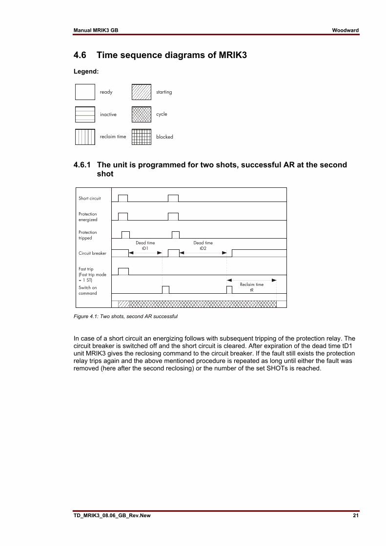
4.6 Time sequence diagrams of MRIK3 Legend:
4.6.1 The unit is programmed for two shots, successful AR at the second shot
Figure 4.1: Two shots, second AR successful
In case of a short circuit an energizing follows with subsequent tripping of the protection relay. The circuit breaker is switched off and the short circuit is cleared. After expiration of the dead time tD1 unit MRIK3 gives the reclosing command to the circuit breaker. If the fault still exists the protection relay trips again and the above mentioned procedure is repeated as long until either the fault was removed (here after the second reclosing) or the number of the set SHOTs is reached.

Woodward Manual MRIK3 GB
22 TD_MRIK3_08.06_GB_Rev.New
4.6.2 The unit is programmed for two shots, unsuccessful AR
Figure 4.2: Two shots, AR unsuccessful
Here the time sequence as described in para. 4.6.1. The second reclosing shot is however unsuc-cessful.
4.6.3 Manual closing of the circuit breaker to faulty lines
Figure 4.3: Manual closing of the C.B. to faulty lines
Unit MRIK3 is in "inactive" status when the circuit breaker is switched off. When the C.B. is manual-ly closed the reclaim time is started. In case there is a faulty line the C.B. is switched off by mains protection of the relay. After elapse of the re-claim time unit MRIK3 changes over to "inactive" status.

Manual MRIK3 GB Woodward
TD_MRIK3_08.06_GB_Rev.New 23
4.6.4 Unsuccessful AR
Figure 4.4: Unsuccessful AR
The sequence diagram illustrates the various possibilities of an unsuccessful AR.

Woodward Manual MRIK3 GB
24 TD_MRIK3_08.06_GB_Rev.New
5. Operations and settings
5.1 Display Function Display shows Pressed push button Corresponding
LED Normal operation SEG Measured operating values Actual measured
values <SELECT/RESET> one time for each value
L1, L2, L3, E
Measuring range overflow max. <SELECT/RESET> L1, L2, L3, E Setting values: Phase (I>; CHAR I>; tI>; I>>; tI>>) Earth (IE>; CHAR IE; tIE>; IE>>; tIE>>)
Current settings Trip delay Characteristics
<SELECT/RESET> one time for each parameter
I>; CHAR I>; tI>; I>>; tI>>;IE>;CHAR IE; tIE> ;IE>> ; tIE>>;
Parameter switch/external trig-gering of the fault recorder
SET1, SET2, B_S2, R_S2, B_FR, R_FR, S2_FR
<+> <-> <SELECT/RESET> P2
Switchable LED-Flash None LED-Flash
FLSH NOFL
<SELECT/RESET> <+><->
Characteristics DEFT, NINV, VINV, EINV, LINV, RINV
<+> <-> <SELECT/RESET> CHAR I>
Characteristics DEFT, NINV, VINV, EINV, LINV, RINV, RXIDG
<+> <-> <SELECT/RESET> CHAR IE>
Reset setting (only available for inverse time characteristics)
0 s / 60 s <SELECT/RESET> <+><->
I> + tRST IE> + tRST
Warning or tripping at earth fault measuring
trip/warn <SELECT/RESET> <+><->
IE>
Setting values AWE: Number of auto reclosing at-tempts Fault time Dead time for 1. - 4. auto reclosing attempt Close impulse time Fault time activation Reclaim time Fast trip mode
setting value in seconds setting value in seconds setting value in seconds 1ST/ALL setting val-ue in seconds 1ST/LAST/EXIT
<SELECT/RESET> <+><-> one time for each value
SHOT tF red tD1, tD2, tD3, tD4 tCI green tI>; I>; I>>; IE>; IE>> tR red I>> + SHOT
Block/Trip-time setting value in seconds
<SELECT/RESET><+><-> I>, I>>, tI>, tI>>, green
Time delay of circuit breaker fail-ure protection tCBFP
setting value in seconds
<SELECT/RESET> <+><->
CB
Blocking of function EXIT <+> until max. setting value LED of blocked parameter
Nominal frequency f=50 / f=60 <SELECT/RESET><+><-> Slave address of serial interface 1-32 <SELECT/RESET><+><-> RS Baud-Rate 1) 1200-9600 <SELECT/RESET><+><-> RS Parity-Check 1) even odd no <SELECT/RESET><+><-> RS Recorded fault data Tripping currents
C.B. tripping time max. pickup time
<SELECT/RESET> one time for each phase, <+><-> for older fault re-cording
L1, L2, L3, E I>, I>>, IE>, IE>> CB
Circuit breaker defect CB?? CB blinking Auto reclosing successful Auto reclosing unsuccessful
CLOS OPEN
0→1 green 0→1 red
Auto reclosing locked-out BLOC After dead time reclosing condi-tion not fulfilled
S/E? 0→1 red CB blinking
Circuit breaker was manually switched on
MANU
Circuit breaker failure protection CBFP CB blinking Display if AR is unsuccessful 0→1 red Trigger signal for the fault re- TEST, P_UP, A_PI, <SELECT/RESET> <+><-> FR

Manual MRIK3 GB Woodward
TD_MRIK3_08.06_GB_Rev.New 25
Function Display shows Pressed push button Corresponding LED
corder TRIP Number of fault occurrences S = 2, S = 4, S = 8 <SELECT/RESET> <+><-> FR Display of date and time Y = 99, M = 10, D = 1,
h = 12, m = 2, s = 12 <SELECT/RESET> <+><->
Change obver the blocking func-tion
PR_B, TR_B <ENTER> und <TRIP>; <+> <->
I>, I>>, IE>, IE>> oder tI>, tI>>, tIE>, tIE>>
Blocking the protection function BLOC, NO_B <+> <-> <SELECT/RESET> I>, I>>, IE>, IE>> AR approved YES/NO <+> <-> <SELECT/RESET> AR + I>
AR + I>> AR + IE> AR + IE>> Running with tD1, tD2, tD3, tD4
Protection steps blocked BLOC <+> <-> <SELECT/RESET> I> I>>
Normal trip time TIME IE> IE>>
Fast trip FAST Running with tD1, tD2, tD3, tD4
Save parameter? SAV? <ENTER> Save parameter! SAV! <ENTER> for about 3 s Software version First part (e.g. A00-)
Sec. part (e.g. 4.01) <TRIP> one time for each part
Manual trip TRI? <TRIP> 3 times Inquire password PSW? <SELECT/RESET>
<+><-><ENTER>
Relay tripped TRIP <TRIP> or after fault tripping
Secret password input XXXX <SELECT/RESET> <+><-><ENTER>
Switch-over LED flash No LED flash
FLSH NOFL
<SELECT/RESET> <+><->
Enquiry failure memory FLT1; FLT2..... <-><+> Delete failure memory wait <-> <SELECT/RESET> System reset SEG <SELECT/RESET>
for about 3 s
Table 5.1: Possible indication messages on the display
1) only Modbus

Woodward Manual MRIK3 GB
26 TD_MRIK3_08.06_GB_Rev.New
5.2 Setting procedure After push button <SELECT/RESET> has been pressed, always the next measuring value is indi-cated. Firstly the operating measuring values are indicated and then the setting parameters. By pressing the <ENTER> push button the setting values can directly be called up and changed.
5.3 Systemparameter 5.3.1 Display of measuring values as primary quantities (Iprim phase) With this parameter it is possible to show the indication as primary measuring value. For this pur-pose the parameter must be set to be equal with the rated primary CT current. If the parameter is set to "sec", the measuring value is shown as a multiple of the rated secondary CT current. Example: The current transformer used is of 1500/5 A. The flowing current is 1380 A. The parameter is set to 1500 A and on the display "1380 A" are shown. If the parameter is set to "sec", the value shown on the display is "0.92" x In. Note: The pick-up value is set to a multiple of the rated secondary CT current.
5.3.2 Display of earth current as primary quantity (Iprim earth) The parameter of this function is to be set in the same way as that de-scribed under 5.3.1. If the parameter is not set to "sec", to relay types MRI3-X and MRI3-XR it applies too, that the measuring value is shown as primary current in ampere. Apart from that the indication refers to % of IN.
5.3.3 Nominal frequency The adapted FFT-algorithm requires the nominal frequency as a parameter for correct digital sam-pling and filtering of the input currents. By pressing <SELECT> the display shows "f=50" or "f=60". The desired nominal frequency can be adjusted by <+> or <-> and then stored with <ENTER>.
5.3.4 Display of the activation storage (FLSH/NOFL) If after an activation the existing current drops again below the pickup value, e.g. I>, without a trip has been initiated, LED I> signals that an activation has occurred by flashing fast. The LED keeps flashing until it is reset again (push button <RESET>). Flashing can be suppressed when the pa-rameter is set to NOFL.

Manual MRIK3 GB Woodward
TD_MRIK3_08.06_GB_Rev.New 27
5.3.5 Parameter switch/external triggering of the fault recorder By means of the parameter-change-over switches it is possible to activate two different parameter sets. Switching over of the parameter sets can either be done by means of software or via the ex-ternal inputs RESET or blocking input. Alternatively, the external inputs can be used for Reset or blocking of the triggering of the fault recorder. Software-parameter
Blocking input used as RESET input used as
SET1 Blocking input RESET input SET2 Blocking input RESET input B_S2 Parameter switch RESET input R_S2 Blocking input Parameter switch B_FR External triggering of the fault recorder RESET input R_FR Blocking input External triggering of the fault recorder S2_FR Parameter switch External triggering of the fault recorder
With the settings SET1 or SET2 the parameter set is activated by soft-ware. Terminals C8/D8 and D8/E8 are then available as external reset in-put or blocking input. With the setting B_S2 the blocking input (D8, E8) is used as parameter-set change-over switch. With the set-ting R_S2 the reset input (D8, E8) is used as parameter-set changeover switch. With the setting B_FR the fault recorder is activated immediately by using the blocking input. On the front plate the LED FR will then light up for the duration of the re-cording. With the setting R_FR the fault recorder is activated via the reset input. With the setting S2_FR parameter set 2 can be acti-vated via the blocking input and/or the fault recorder via the reset input. The relevant function is then activated by applying the auxiliary voltage to one of the external in-puts. Important note: When functioning as parameter change over facility, the external input RESET is not available for resetting. When using the external input BLOCKING the protection functions must be deactivated by software blocking separately (refer to chapter 5.7.1).

Woodward Manual MRIK3 GB
28 TD_MRIK3_08.06_GB_Rev.New
5.4 Parameter protection 5.4.1 Pickup current for phase over current element (I>) The setting value for this parameter that appears on the display is related to the nominal current (IN) of the relay. This means: pickup current (Is) = displayed value x nominal current (IN) e.g. dis-played value = 1.25 then, Is = 1.25 x IN.
5.4.2 Time current characteristics for phase over current element (I> + CHAR)
By setting this parameter, one of the following 6 messages appears on the display: DEFT - Definite Time (Type A) NINV - Normal Inverse (Type B) VINV - Very Inverse (Type C) EINV - Extremely Inverse LINV - Long Time Inverse RINV - RI - Inverse Anyone of these four characteristics can be chosen by using <+> <->-push buttons, and can be stored by using <ENTER>-push button.
5.4.3 Trip delay or time multiplier for phase over current element (tI>) Usually, after the tripping characteristic is changed, the time delay or the time multiplier should be changed accordingly. In order to avoid an unsuitable arrangement of relay modes due to careless-ness of the operator, the following precautions are taken: After the change of the characteristic setting, the setting process turns to the time delay setting au-tomatically. The LED tI> is going to flash yellow to remind the operator to change the time delay setting accordingly. After pressing the <SELECT>-push button, the present time delay setting value is shown on the display. The new setting value can then be changed by using <+> <-> -push but-tons. If, through a new setting, another relay characteristic other than the old one has been chosen (e.g. from DEFT to NINV), but the time delay setting has not been changed despite the warning from the flashing LED, the relay will be set to the most sensitive time setting value of the selected characte-ristics after five minutes warning of flashing LED tI>. The most sensitive time setting value means the fastest tripping for the selected relay characteristic. When the time delay or the time multiplier is set out of range (Text "EXIT" appears on the display), the low set element of the over current relay is blocked. The "WARN"-relay will not be blocked.
5.4.4 Reset setting for inverse time tripping characteristics in the phase current path
To ensure tripping, even with recur-ring fault pulses shorter than the set trip delay, the reset mode for all tripping characteristics can be switched over. If the adjustment RST is set at 60 s, the trip-ping time is only reset after 60 s faultless condition. This function is not avail-able if RST is set to 0. With interruption of the fault current the trip delay is reset immediately and started again at recur-ring fault current.

Manual MRIK3 GB Woodward
TD_MRIK3_08.06_GB_Rev.New 29
5.4.5 Current setting for high set element (I>>) The current setting value of this parameter appearing on the display is related to the nominal cur-rent of the relay. This means: I>> = displayed value x IN. When the current setting for high set element is set out of range (on display appears "EXIT"), the high set element of the over current relay is blocked. The high set element can be blocked via terminals E8/D8 if the corresponding blocking parameter is set to BLOC (refer to 5.7.1).
5.4.6 Trip delay for high set element (tI>>) Independent from the chosen tripping characteristic for I>, the high set element I>> has always a definite-time tripping characteristic. An indication value in seconds appears on the display.
5.4.7 Pickup current for earth fault element (IE>) Similar to the chapter 5.4.1.
5.4.8 WARN/TRIP changeover A detected earth fault can be parameterized as follows. After delay time a) "warn" only the alarm relay trips b) "trip" the trip relay trips and tripping values are stored.
5.4.9 Time current characteristics for earth fault element (CHAR IE) By setting this parameter, one of the following 7 messages appears on the display: DEFT - Definite Time NINV - Normal inverse (Type A) VINV - Very inverse (Type B) EINV - Extremely inverse (Type C) RINV - RI-Inverse LINV - Long Time Inverse RXID - Special characteristic Anyone of these seven characteristics can be chosen by using <+> <->-push buttons, and can be stored by using <ENTER>-push button.
5.4.10 Trip delay or time multiplier for earth fault element (tIE>>) Similar to the chapter 5.4.3.
5.4.11 IE> Tripping is blocked at IE>>Alarm If the current of an earth fault is that high as to initiate excitation of IE>>, a potential tripping of the IE> step will be blocked. The display shows “YES” if IE> is to be blocked and “NO”, if blocking shall be suppressed.

Woodward Manual MRIK3 GB
30 TD_MRIK3_08.06_GB_Rev.New
5.4.12 Current setting for high set element of earth fault supervision (IE>>) Similar to the chapter 5.4.5.
5.4.13 Trip delay for high set element of earth fault supervision (tIE>>) Similar to the chapter 5.4.6.
5.4.14 Parameters auto reclosing Number of AR-SHOTS Indicates how often the circuit breaker may switch on again when a fault occurs.
5.4.15 Fault time (tF) Reclosing is permitted during this time. It starts with the energizing of the corresponding protection devices. A reclosing attempt follows only if the command time of the protection devices is shorter than the fault time set at MRIK3.
5.4.16 Dead time (tD) Starts with the OFF-signal of the circuit breaker. No closing command to the circuit breaker is given till expiration of the set dead time.
5.4.17 Close impulse time (tCI) During close impulse time tCI the NO C.B. contact of MRIK3 is closed. It starts with expiration of the dead time and is interrupted earlier when the ON-signal of the circuit breaker is already present before expiration of the time.
5.4.18 Reclaim time (tR) This is the time during which - after switching on (also manually) or after AR - a subsequent reclos-ing is prevented. If the number of the set shots is reached, the MRIK3 is blocked for this time after the last reclosing attempt. The reclaim time is started with the automatic closing command or by switching on manually. An OFF-command which occurs after the last permissible AR leads to a final switching-off.
5.4.19 Fault time activation This parameter can be used to fix whether the supervision of the fault time is active for the first trip-ping action or for all tripping actions (see 5.4.15).

Manual MRIK3 GB Woodward
TD_MRIK3_08.06_GB_Rev.New 31
5.4.20 Block/Trip - time The block/trip time serves for detection of a c.b. failure protection by rear interlocking. It is activated by setting the blocking input D8/E8 and by setting the parameter to TR_B. After the set block/trip time has expired, the relay can be tripped if the excitation of a protective function has been applied the delay time of which has expired and the blocking function is still active. If the parameter PR_B is set, the individual protection stages are blocked (refer to Chapter 5.7.1).
5.4.21 Circuit breaker failure protection tCBFP The C.B. failure protection is based on supervision of the phase currents during tripping of the re-lay. This protective function becomes only active after tripping and it is then checked whether all phase currents have dropped to 0 within time tCBFP (Circuit Breaker Failure Protection). Should not all phase currents have dropped within this time (tCBFP can be adjusted from 0.1 - 2.0 s), the protection device diagnoses C.B. failure and the respective assigned relay is activated. The C.B. failure protection function is deactivated again, when all phase currents drop to 0 within tCBFP.
5.4.22 Adjustment of the slave address Pressing push buttons <+> and <-> the slave address can be set in range of 1-32.
5.4.23 Setting of Baud-rate (applies for Modbus Protocol only) Different transmission rates (Baud rate) can be set for data transmission via Modbus protocol. The rate can be changed by push buttons <+> and <-> and saved by pressing <ENTER>.
5.4.24 Setting of parity (applies for Modbus Protocol only) The following three parity settings are possible • "even" = even • "odd" = odd • "no" = no parity check The setting can be changed by push buttons <+> and <-> and saved by pressing <ENTER>.

Woodward Manual MRIK3 GB
32 TD_MRIK3_08.06_GB_Rev.New
5.5 Fault recorder The MRI3 is equipped with a fault recorder (see chapter 3.7). Three parameters can be deter-mined.
5.5.1 Number of the fault recordings The number of max. recordings requested has to be determined in advance. There is a choice of (1)* 2, (3)* 4 or (7)* 8 recordings and de-pendent on this the duration of the individual fault record-ings is defined, i.e. (1)* 2 recordings for a duration of 8 s (with 50 Hz) (6.66 s with 60 Hz) (3)* 4 recordings for a duration of 4 s (with 50 Hz) (3.33 s with 60 Hz) (7)* 8 recordings for a duration of 2 s (with 50 Hz) (1,66 s with 60 Hz) * is written over when a new trigger signal arrives
5.5.2 Adjustment of trigger occurrences There is a choice between four different occurrences: P_UP (Pickup) Storage is initiated after recognition of a general activation. TRIP Storage is initiated after a trip has occurred. A_PI (After Pickup) Storage is initiated after the last activation threshold was fallen short of. TEST Storing is activated by simultaneous actuation of the keys <+> and <->. During the recording time the display shows “Test”.
5.5.3 Pre-trigger time (Tpre) By the time Tpre it is determined which period of time prior to the trigger occurrence should be stored as well. It is possible to adjust a time between 0.05 s and 8 s. With keys <+> and <-> the values can be changed and with <ENTER> be saved.
5.6 Adjustment of the clock When adjusting the date and time, LED lights up. The adjustment method is as follows: Date: Year Y=00 Month M=00 Day D=00 Time: Hour h=00 Minute m=00 Second s=00 The clock starts with the set date and time as soon as the supply voltage is switched on. The time is safe-guarded against short-term voltage failures (min. 6 minutes). Note: The window for parameter setting is located behind the measured value display. The parameter window can be accessed via the <SELECT/RESET> key.

Manual MRIK3 GB Woodward
TD_MRIK3_08.06_GB_Rev.New 33
5.7 Additional functions 5.7.1 Blocking the protection functions, assignment of the output relays
and AR - functions Blocking of the protective functions: The MRIK3 is equipped with a blocking function that can be parameterized arbitrary. Connecting supply voltage to terminals D8/E8 blocking of those functions which were selected by the user takes place. It is possible to choose between two types of protective blocking: 1. Blocking of the individual protection stages. The excitation of the blocked protection stage is blocked.. 2. Blocking of the individual trip-ping stages. The individual protection stages are excited and the set tripping time expires. Trip-ping only takes place when: a) the voltage at the blocking in-put D8/E8 is reduced; b) the voltage at the blocking in-put D8/E8 is applied, the tripping time and the blocking time have expired. (refer to Chapter 5.4.17) Parameter setting is to be carried out as follows: • After the <ENTER> and <TRIP> keys have been actuated simultaneously, the display shows the text "PR_B" (the protection stages are blocked) or "TR_B" (the tripping stages are blocked). • The settings can be changed by actuating the keys <+> or <->. In this procedure, the LEDs I>; I>>; IE>; IE>> are simultaneously alight in case of protective blocking "PR_B" and LEDs tI>; tI>>; tIE>, tIE>> simultaneously emit light in case of trip blocking "TR_B". • Actuation of the <ENTER> key with a one-time entry of the password will store the set function. • After this actuate the <SELECT/RESET> key to call up the first block able protection function. • The display will show the text "BLOC" (the respective function is blocked) or "NO_B" (the respective function is not blocked. • Actuation of the <ENTER> key will store the set function. • By pressing the <SELECT/RESET> pushbutton, all further protective function that can be blocked are called one after the other. • After selection of the last blocking function renewed pressing of the <SELECT/RESET> pushbutton switches to the assignment mode of the output relays. Function Display LED/Colour I> Over current
(Low set) NO_B I> green
I>> Over current (High set)
BLOC I>> green
IE> Earth current 1. element
NO_B IE> green
IE>> Earth current 2. element
NO_B IE>> green
CBFP Circuit breaker failure protection NO_B CB yellow Table 5.2: Default settings for both parameter sets

Woodward Manual MRIK3 GB
34 TD_MRIK3_08.06_GB_Rev.New
Assignment of the output relays: Unit MRIK3 has five output relays. The fifth output relay, provided as permanent alarm relay for self super-vision is normally on. Output relays 1 - 4 are normally off and can be assigned as alarm or tripping relays to the current functions which can either be done by using the push but-tons on the front plate or via serial interface RS485. The assignment of the output relays is similar to the setting of parameters, however, only in the assignment mode. The assignment mode can be reached only via the blocking mode. By pressing push button <SELECT/RESET> in blocking mode again, the assignment mode is se-lected. Definition: Alarm relays are activated at pickup. Tripping relays are only activated after elapse of the tripping delay. The relays are assigned as follows: • LEDs I>, I>>, IE>, IE>> are two-colored and light up green when the output relays are assigned as alarm relays and red as tripping relays. • After the assignment mode has been activated, first LED I> lights up green. Now one or several of the four output relays can be assigned to current element I> as alarm relays. At the same time the selected alarm relays for frequency element 1 are indicated on the display. • Indication "1_ _ _" means that out-put relay 1 is assigned to this cur-rent element. When the display shows "_ _ _ _", no alarm relay is as-signed to this current element. • The assignment of output relays 1 - 4 to the current elements can be changed by pressing <+> and <-> push buttons. • The selected assignment can be stored by pressing push button <ENTER> and sub- sequent input of the password. • By pressing push button <SELECT/RESET>, LED I> lights up red. The output relays can now be assigned to this current element as tripping relays. Relays 1 - 4 are selected in the same way as de-scribed before. • By repeatedly pressing of the <SELECT/RESET> push button and assignment of the relays all elements can be assigned separately to the relays. • After the last relay assignment, press <SELECT/RESET> once more to move on to the assignment of the AWE functions.
Note: The function of jumper J2 and J3 de-scribed in general description "MR Digital Multifunctional Re-lays" have no function. For relays without assignment mode this jumpers are used for parameter setting of alarm relays (activation at pickup or tripping and manual reset).

Manual MRIK3 GB Woodward
TD_MRIK3_08.06_GB_Rev.New 35
Relay function Output relays Display- Lighted LED 1 2 3 4 indication I> alarm X _ 2 _ _ I>: green tripping X 1 _ _ _ tI>: red I>> alarm X _ 2 _ _ I>>: green tripping X 1 _ _ _ tI>>: red I>>FAST
TRIP tripping X 1 _ _ _ I>/I>>:
green + CB green
IE> alarm X _ 2 _ _ IE>: green tripping X 1 _ _ _ tIE>: red IE>> alarm X _ 2 _ _ IE>>: green tripping X 1 _ _ _ tIE>>: red CBFP tripping X _ _ 3 _ CB green AWE switch on X _ _ _ 4 AR yellow + tCI green AWE Unsuccess-
ful X _ _ 3 _ AR yellow + O→I red
Table 5.3: Example of assignment matrix of the output relay (default settings)
Assignment of the AR functions The last activation of the <SELECT/RESET> key in the relay assignment mode will activate the AR assignment mode. • The accompanied LEDs indicate which functions will be assigned to the individual protection stages for parameter setting before the 1st AR. • Actuation of the <+> <-> keys permits switching over between "BLOC", "TIME" or "FAST". Here the following functions are activated or deactivated one after the other. 1. "BLOC" blocking of the protective functions. 2. "TIME" tripping of the individual protective functions with set de-lay time. 3. "FAST" tripping with Fast Trip function. • Actuation of the <ENTER> key with subsequent one-time entry of the pass word will store the altered value. • Actuation of the <SELECT/RESET> key will assign the tripping function before the 1st AR, one after the other to the individual protection stages. • After this adjustment the parameters are set for activation of the 1st AR. • The accompanied LEDs indicate which protective functions are available for parameter setting for the first AR. • Actuation of the <+> <-> keys permits switching over between "YES" and "NO". "YES" means that the selected protection function will trigger an AR. • Actuation of the <ENTER> key with subsequent one-time entry of the password will store the altered value. • Actuation of the <SELECT/RESET> key the protective functions are, one after the other, assigned to the first AR. The following table shows all parameters that have to be set. After each group the setting changes between parameter set 1 and 2.
Function Protection step Display-indication corresponding LED
trip I> TIME I> + tD1 before the I>> TIME I>> + tD1 1st AR IE> TIME IE> + tD1 IE>> TIME IE>> + tD1

Woodward Manual MRIK3 GB
36 TD_MRIK3_08.06_GB_Rev.New
Function Protection step Display-indication corresponding LED Activation I> NO AR + I> + tD1 Of the 1st AR I>> YES AR + I>> + tD1 per IE> NO AR + IE> + tD1 IE>> NO AR + EI>> + tD1 Function Protection step Display-indication corresponding LED Trip I> TIME I> + tD1 after the I>> TIME I>> + tD1 1st AR IE> TIME IE> + tD1 IE>> TIME IE>> + tD1 Function Protection step Display-indication corresponding LED Activation I> NO AR + I> + tD2 Of the 2nd I>> YES AR + I>> + tD2 AR per IE> NO AR + IE> + tD2 IE>> NO AR + EI>> + tD2 Function Protection step Display-indication corresponding LED Trip I> TIME I> + tD2 After the I>> TIME I>> + tD2 2nd AR IE> TIME IE> + tD2
IE>> TIME IE>> + tD2 Function Protection step Display-indication corresponding LED Activation I> NO AR + I> + tD3 of the I>> YES AR + I>> + tD3 3rd AR per IE> NO AR + IE> + tD3 IE>> NO AR + EI>> + tD3 Function Protection step Display-indication corresponding LED Trip I> TIME I> + tD3 After the I>> TIME I>> + tD3 3rd AR IE> TIME IE> + tD3 IE>> TIME IE>> + tD3 Function Protection step Display-indication corresponding LED Activation I> NO AR + I> + tD4 of the 4th AR I>> YES AR + I>> + tD4 per IE> NO AR + IE> + tD4 IE>> NO AR + EI>> + tD4 Function Protection step Display-indication corresponding LED trip I> TIME I> + tD4 after the I>> TIME I>> + tD4 4th AR IE> TIME IE> + tD4 IE>> TIME IE>> + tD4
Table 5.4: Assignment of AR functions
The assignment mode can be terminated at any time by pressing the <SELECT/RESET> push but-ton for some time (abt. 3 s). A form is attached to this description where the setting requested by the customer can be filled-in. This form is prepared for telefax transmission and can be used for your own reference as well as for telephone queries.

Manual MRIK3 GB Woodward
TD_MRIK3_08.06_GB_Rev.New 37
5.8 Indication of measuring and fault values 5.8.1 Indication of measuring values The following measuring quantities can be indicated on the display during normal service: • Apparent current in phase 1 (LED L1 green), • apparent current in phase 2 (LED L2 green), • apparent current in phase 3 (LED L3 green), • apparent earth current (LED E green)
5.8.2 Unit of the measuring values displayed The measuring values can optionally be shown in the display as a multiple of the "sec" rated value (x ln) or as primary current (A). According to this the units of the display change as follows: Phase current Indication as Range Unit Secondary current 0.00 – 40.0 x In Primary current .000 – 999.
k000 – k999 1k00– 9k99 10k0 – 99k0 100K – 999k 1M00 – 2M00
A kA* kA kA kA MA
Table 5.5: Ranges of phase currents from 2kA prim transformerrated current
Earth current Indication as Range Unit Secondary current .000 – 15.0 x In Primary current .000 – 999.
k000 – k999 1k00 – 9k99 10k0 – 99k0 100k – 999k 1M00 – 2M00
A kA* kA kA kA MA
Table 5.6: Ranges of phase currents from 2kA prim transformer rated current
5.8.3 Indication of fault data All faults detected by the relay are indicated on the front plate optically. For this purpose, the four LEDs (L1, L2, L3, E) and the four function LEDs (I>, I>>, IE> und IE>>) are equipped at MRIK3. If, for example an over current occurs, first the respective phase LEDs will light up. LED I> lights up at the same time. After tripping the LEDs are lit permanently.

Woodward Manual MRIK3 GB
38 TD_MRIK3_08.06_GB_Rev.New
5.9 Fault memory When the relay is energized or trips, all fault data and times are stored in a non-volatile memory. The MRIK3 is provided with a fault value recorder for max. 8 fault occurrences. In the event of addi-tional trippings always the oldest data set is written over. For fault indication not only the trip values are recorded but also the status of LEDs. Fault values are indicated when push buttons <-> or <+> are pressed during normal measuring value indication. • Normal measuring values are selected by pressing the <SELECT/RESET> button. • When then the <-> button is pressed, the latest fault data set is shown. By repeated pressing the <-> button the last but one fault data set is shown etc. For indication of fault data sets abbreviations FLT1, FLT2, FLT3, ... are displayed (FLT1 means the latest fault data set recorded). At the same time the parameter set active at the occurrence is shown. • By pressing <SELECT/RESET> the fault measuring values can be scrolled. • By pressing <+> it can be scrolled back to a more recent fault data set. At first FLT3, FLT2, FLT1 are always displayed. • When fault recording is indicated (FLT1 etc.), the LEDs flash in compliance with the stored trip information, i.e. those LEDs which showed a continuous light when the fault occurred are now blinking to indicate that it is not a current fault. LEDs which were blinking during trip conditions, (element had picked up) just briefly flash. • If the relay is still in trip condition and not yet reset (TRIP is still displayed), no measuring values can be shown. • To delete the trip memory, the push button combination <SELECT/RESET> and <-> has to be pressed for about 3 s. The display shows 'wait'. Recorded fault values: Value displayed Relevant LED Phase currents L1, L2, L3 in I/In L1, L2, L3 Earth current IE in I/IEn E C.B. switching time in s 1) C.B. Expired tripping time of I> in % of tI> 2) I> Expired tripping time of IE> in % of tIE> 2) IE> Time stamp Date: Y = 99 M = 04 D = 20
time: h = 11 m = 59 s = 13
Table 5.7: Recorded fault values
1) C.B. switching time: Time between energizing of the trip output relay and switching of the C.B. (current < 1 % IN). 2) Expired tripping time: Time between pickup and release of the low set element. This value is only displayed for I> and IE>.
Manual MRIK3 GB Woodward
TD_MRIK3_08.06_GB_Rev.New 39
5.10 Reset Unit MRIK3 has the following three possibilities to reset the relay: Manual Reset • Pressing the push button <SELECT/RESET> for some time (about 3 s) Electrical Reset • Through applying auxiliary voltage to C8/D8 Software Reset • The software reset has the same effect as the <SELECT/RESET> push button (see also communication protocol of RS485 interface). The display can only be reset when the pickup is not present anymore (otherwise "TRIP" remains in display). During resetting of the display the parameters are not affected.
5.10.1 Erasure of fault storage The fault storage is erased by pressing the key combination <SELECT/RESET> and <-> for about 3 s. At the display "Wait" appears.

Woodward Manual MRIK3 GB
40 TD_MRIK3_08.06_GB_Rev.New
6. Relay testing and commissioning The test instructions following below help to verify the protection relay performance before or dur-ing commissioning of the protection system. To avoid a relay damage and to ensure a correct relay operation, be sure that: • The auxiliary power supply rating corresponds to the auxiliary voltage on site, • the rated current of the relay corresponds to the plant data on site, • the current transformer circuits and voltage transformer circuits are connected to the relay correctly, • all signal circuits and output relay circuits are connected correctly.
6.1 Power-On NOTE! Prior to switch on the auxiliary power supply, be sure that the auxiliary supply voltage corresponds to the rated data on the type plate. Switch on the auxiliary power supply to the relay and check that the message "SEG" appears on the display and the self supervision alarm relay (watchdog) is energized (Contact terminals D7 and E7 closed).
6.2 Testing the output relays and LEDs NOTE! Prior to commencing this test, interrupt the trip circuit to the circuit breaker if tripping is not desired. By pressing the push button <TRIP> once, the display shows the first part of the software version of the relay (e.g. „D01-“). By pressing the push button <TRIP> twice, the display shows the second part of the software version of the relay (e.g. „1.00“). The software version should be quoted in all correspondence. Pressing the <TRIP> button once more, the display shows "PSW?". Please enter the correct password to proceed with the test. The message "TRI?" will follow. Confirm this mes-sage by pressing the push button <TRIP> again. All output relays and LEDs should then be acti-vated and the self supervision alarm relay (watchdog) be deactivated one after another with a time interval of 1 second. In the same manner all LEDs are activated at 0.5 s intervals. Two-colored LEDs always change from red to green in this process. There-after, reset all output relays back to their normal positions by pressing the push button <SELECT/RESET> (about 3 s).
6.3 Checking the set values By repeatedly pressing the push button <SELECT>, all relay set values may be checked. Set value modification can be done with the push button <+><-> and <ENTER>. For detailed in-formation about that, please refer to chapter 5.

Manual MRIK3 GB Woodward
TD_MRIK3_08.06_GB_Rev.New 41
6.4 Secondary injection test 6.4.1 Test equipment • Voltmeter, Ammeter with class 1 or better, • auxiliary power supply with the voltage corresponding to the rated data on the type plate, • single-phase current supply unit (adjustable from 0 to ≥ 4 x In), • timer to measure the operating time (Accuracy class ≥ ±10 ms), • switching device • Test leads and tools
6.4.2 Example of test circuit for MRIK3 relays For testing MRIK3 relays only current input signals are required. Figure 6.1 shows a simple exam-ple of a single phase test circuit with adjustable current energizing the MRIK3 relay under test. Note! Care must be taken that the correct functions are assigned to the output relays (refer to 5.7). In this example, relay 1 is assigned to the trip-ping function and relay 4 to the auto reclosing function.
Figure 6.1:Test curcuit

Woodward Manual MRIK3 GB
42 TD_MRIK3_08.06_GB_Rev.New
6.4.3 Checking the input circuits and measured values Inject a current, which is less than the relay pickup current set values, in phase 1 (terminals B3-B4), and check the measured current on the display by pressing the push button <SELECT>. For a relay with rated cur-rent IN = 5A, for example, a secondary current injection of 1A should be in-dicated on the display with about 0.2 (0.2 x IN). When parameter Iprim = „sek“ is set, the indication is 0.2 x In and at „5“ the indication is 1.00 [A]. The current can be also injected into the other cur-rent input circuits (Phase 2: terminals B5-B6, Phase 3: terminals B7-B8 and the earth current in-put). Compare the displayed current value with the reading of the ammeter. The deviation must not exceed 3% of the measuring value or 1% IN. By using an RMS-metering instrument, a greater dev-iation may be observed if the test current contains harmonics. Because the MRIK3 relay measures only the fundamental component of the input signals, the harmonics will be rejected by the internal DFFT-digital filter. Whereas the RMS-metering instrument measures the RMS-value of the input signals.
6.4.4 Checking the operating and resetting values of the relay Inject a current which is less than the relay set values in phase 1 of the relay MRIK3 and gradually in-crease the current until the relay starts, i.e. at the moment when the LED I> and L1 light up or the alarm output relay I> is activated. Read the operating current indicated by the ammeter. The deviation (MRIK3) must not exceed 3% of the set operating value or 1% IN. Furthermore, gradually decrease the current until the relay resets, i.e. the alarm output relay I> is disengaged. Check that the resetting cur-rent is smaller than 0.97 times the operating current. Repeat the test on phase 2, phase 3 and earth current input circuits in the same manner. (Accuracy of earth current measuring ±3% of measuring value).
6.4.5 Checking the relay operating time "For this test the AR function should be deactivated. The number of automatic reclosing attempts "SHOT" should be set to "EXIT". To check the relay operating time, a timer must be connected to the trip output relay contact. The timer should be started simultaneously with the current injection in the current input circuit and stopped by the trip relay contact. Set the current to a value corresponding to twice the operating value and inject the current instantaneously. The operating time measured by the timer should have a deviation of less than 3% of the set value or ±10 ms (DEFT). Accuracy for inverse time cha-racteristics refer to IEC 255-3. Repeat the test on the other phases or with the inverse time characteristics in the similar manner. In case of inverse time characteristics the injected current should be selected according to the cha-racteristic curve, e.g. two times IS. The tripping time may be red from the characteristic curve dia-gram or calculated with the equations given under "technical data". Please observe that during the secondary injection test the test current must be very stable, not deviating more than 1%. Otherwise the test results may be wrong.
6.4.6 Checking the high set element of the relay Set a current above the set operating value of I>>. If required an alarm relay can be tripped if in this moment if it is assigned to this function. Check the tripping time of the high set element according to chapter 6.4.5. Check the accuracy of the operating current setting by gradually increasing the injected current un-til the I>> element picks up. Read the current value from the ammeter and compare it with the de-sired setting. Repeat the entire test on other phases and earth current input circuits in the same manner. Note ! Where test currents >4 x IN are used, the thermal withstand capability of the current paths has to be considered (see technical data, chapter 7.1).

Manual MRIK3 GB Woodward
TD_MRIK3_08.06_GB_Rev.New 43
6.4.7 Checking the auto reclosing function The auto reclosing function can only be tested by means of an auxiliary relay simulating the C.B. and a push button for manual start. In order to simplify testing, the significant settings of the devic-es and the value of the test current are provided as follows: I> = 0,8 x IN I> +CHAR = DEFT tI> = 2 s I>> = 1,2 x IN tI>> = 0,5 s SHOT = 1 tF = 1,5 tD1 = 5 s tD2 = 10 s tCI = 0,2 s tR = 10 s tF + I>,I>>(IE>,IE>>) = 1ST CB (tCBFP) = 2 s (EXIT) fN = 50 Hz or 60 Hz Relay assignment: refer to default settings AR-assignment: I> = YES I>> = YES The test circuit must be set up in accordance with Figure 6.1. First the push button is pressed. The auxiliary relay picks up and the LED CB lights up. With the settings of the devices as shown above, a test current of 1.5 x IN should be injected on phase L1. When the pickup value is exceeded, trip-ping takes place at once and the LEDs I>> and L1 light up red. The auxiliary relay releases again. The device changes into the "Starting" status. This is signaled by the LED AR. Now the dead time is running and the LED tD1 lights up green. After expiration of the dead time the LED tCI briefly lights up and the auxiliary relay trips again. The display shows "CLOS". The LED AR is alight furthermore, the O→I lights up green and the LED tR lights up red. The LED tR signals that the reclaim time is running. Once it has expired, all LEDs extinguish except for the LED CB, and the display shows "SEG" again. This completes a successful AR simulation. Note: After the relay has tripped, the test current should be switched off as quickly as possible. Other-wise, there is the danger that the switch failure protection device CBFP picks up. If switching off quickly is impossible, tCBFP must be set to "EXIT".
6.4.8 Checking the circuit breaker position (A2/A7 and A2/A5) The aux. voltage has to be applied at terminals A2/A7). LED tR (reclaim time) and the LED CB light up. After the delay time has elapsed, LED tR extinguishes and LED AR lights up. This signals that the relay is ready for AR function. Input A2-A5 (C.B. ready) must be „ON“. Without voltage signal at terminals A2/A5 LED CB flashes and the display shows „CB??“.
6.4.9 Checking the AR-blocking input (A2/A3) Connect auxiliary voltage to terminals A2/A3. The display shows "BLOC". If the signal at terminals A2/A3 is cancelled, the LED extinguishes and the display shows "SEG" again.

Woodward Manual MRIK3 GB
44 TD_MRIK3_08.06_GB_Rev.New
6.4.10 Checking the external blocking and reset functions By means of the external blocking in-put, it is possible to block all protective functions. To give an example, the blocking function of the phase current high set element is de-scribed. This can be tested by first setting the parameter for the phase current high set element to „BLOC“ and then connecting the auxiliary voltage to terminals E8/D8. The phase current low set element I> should be set to EXIT for this test. Inject a test current which could cause a high set (I>>) tripping. Observe that there is no trip of any assigned output relay of the high set or low set element. Remove the auxiliary supply voltage from the blocking input. Inject a test current to trip the relay (message „TRIP“ on the display). Interrupt the test current and apply auxiliary supply voltage to the external reset input of the relay (terminals C8/D8). The display and LED indications should be reset immediately.
6.4.11 Testing the external blocking with Block/Trip function In order to simplify things, the short-circuit stage is to be tested here as described in Chapter 6.4.10. For this purpose, the parameter for the Block/Trip function must be set to "TR_B" (first value in the blocking menu of the protection functions Chapter 5.7.1. The appertaining Block/Trip time should be longer than the set tripping time tI>> (see chapter 5.4.20). Here, too, a current is impressed which should make the short-circuit stage trip. After the Block/Trip time has expired, tripping will take place. Tripping takes place when: • the blocking input has been set • a tripping stage has been excited • the appertaining tripping time has expired • the Block/trip time has expired If the Block/Trip time is set shorter than the tripping time, tripping will only take place after the trip-ping time has expired.
6.4.12 Test of the CB failure protection For testing the tripping time a test current of about two times the rated current to be injected. The timer is started upon tripping of the relay of a protection function (I>, I>>, IE>, IE>>) and stopped as soon as the relay for the CB failure protection has picked up. Message "CBFP" is displayed. The tripping time ascertained by the timer should not deviate more than 1% or, at short trip delay, less than ±10 ms from the set tripping time. Alternatively, the timer can be started when the aux. voltage and the test current are injected simul-taneously. The timer stops when the corresponding output relay for circuit breaker failure protection trips. In this case the previously measured tripping delay has to be subtracted from the total tripping time measured.

Manual MRIK3 GB Woodward
TD_MRIK3_08.06_GB_Rev.New 45
6.5 injection test Generally, a primary injection test could be carried out in the similar manner as the secondary in-jection test described above. With the difference that the protected power sys-tem should be, in this case, connected to the installed relays under test „on line“, and the test currents and voltages should be injected to the relay through the current and voltage transformers with the primary side energized. Since the cost and potential hazards are very high for such a test, primary injection tests are usually limited to very important protective relays in the power system. Because of its powerful combined indicating and measuring functions, the MRIK3 relay may be tested in the manner of a primary injection test with-out extra expenditure and time consumption. In actual service, for example, the measured current values on the MRIK3 relay display may be compared phase by phase with the current indications of the ammeter of the switchboard to verify that the relay works and measures correctly: • Close the circuit beaker manually and check that the LED tR (Reclaim time) and CB light up. After the preset delay time, the LED tR is extinguished to indicate that the relay is ready for auto reclosing. • Open the circuit breaker manually and check that the LED CB is extinguished immediately to indicate that the circuit breaker is not ready for auto-reclosing.
6.6 Maintenance Maintenance testing is generally done on site at regular intervals. These intervals vary among us-ers depending on many factors: e.g. the type of protective relays employed; the importance of the primary equipment being protected; the user's past experience with the relay, etc. For electromechanical or static re-lays, maintenance testing will be performed at least once a year ac-cording to the experiences. For digital relays like MRIK3, this interval can be substantially long-er. This is because: • The MRIK3 relays are equipped with very wide self-supervision functions, so that many faults in the relay can be detected and signalized during service. Important: The self- supervision output relay must be connected to a central alarm panel! • The combined measuring functions of MRIK3 relays enable supervision the relay functions during service. • The combined TRIP test function of the MRIK3 relay allows to test the relay output circuits. A testing interval of two years for maintenance will, therefore, be recommended. During a maintenance test, the relay functions including the operating values and relay tripping characteristics as well as the operating times should be tested.

Woodward Manual MRIK3 GB
46 TD_MRIK3_08.06_GB_Rev.New
7. Technical data For additional common data of all MR-relays please refer to manual "MR - Digital Multifunctional relays".
7.1 Measuring input circuits Rated data: Nominal current IN 1 A or 5 A Nominal frequency fN 50 Hz; 60 Hz adjustable Measuring range: Phase current: 0 – 40 x IN Earth current: 0 – 16 x IN Measuring range of I/Is: Phase current: up to 32 x Is Earth current: up to 32 x Is Earth current RXIDG-characteristic: up to 70 x Is Power consumption in current circuit: at IN = 1 A 0.2 VA at IN = 5 A 0.1 VA Thermal withstand capability in current circuit: dynamic current withstand (half-wave) 250 x IN for 1 s 100 x IN for 10 s 30 x IN continuously 4 x IN
7.2 Common data Dropout to pickup ratio: >97% Dropout to pickup ratio for phase current in range 0.2 x IN to 0.5 x IN: = 100 % Returning time: 30 ms Time lag error class index E: ±10 ms Minimum operating time: 30 ms Transient overreach at instantaneous operation: ≤5% Influences on the current measurement: Auxiliary voltage: in the range of 0.8 <UH / UHN <1.2 no additional influences can be measured Frequency: in the range of 0.9 < f/fN < 1.1; <0.2% / Hz Harmonics: up to 20% of the third harmonic; <0.08% per percent of the third harmonic up to 20% of the fifth harmonic; <0.07% per per-cent of the fifth harmonic Influences on delay times: no additional influences can be measured

Manual MRIK3 GB Woodward
TD_MRIK3_08.06_GB_Rev.New 47
7.3 Setting ranges and steps 7.3.1 Time overcurrent protection Setting range Step Tolerance Iprim (SEK) 0.002...50 kA 0.001; 0.002; 0.005; 0.01; 0.02; 0.05;
0.1; 0.2
I> tI>
0.2...4.0 x IN (EXIT) 0.03 – 260 s (EXIT) (definite time) 0.05 - 10 (EXIT) (inverse time)
0.01, 0.02, 0.05; 0.1 x IN 0.01; 0.02; 0.1; 0.2; 0.5; 1.0; 2.0; 5.0 10.0; 20.0 s 0.01; 0.02; 0.05; 0.1; 0.2
±3% from set value or min. ±1% IN ±3% or ±10 ms ±3% of the measuring val-ue of the current or ±20 ms (see EN60255-3).
I>> tI>>
0,5...40 x IN (EXIT) 0.03...10 s (EXIT)
0.02; 0.05; 0.1; 0.2; 0.5; 1.0 x IN 0.01 s; 0.02 s; 0.05 s; 0.1 s; 0.2 s
±3% from set value or min. ±1% IN ±3% or ±10 ms
Table 7.1: Setting ranges for time over current protection
7.3.2 Earth fault protection Setting range Step Tolerance Iprim (SEK) 0.002...50 kA 0.001; 0.002; 0.005; 0.01; 0.02; 0.05;
0.1; 0.2
IE> tIE>
0.01...2.0 x IN (EXIT) 0.03 – 260 s (EXIT) (definite time) 0.06 – 10 (EXIT) (inverse time) 0,05 – 1,00 (EXIT) (inverse time only RXIDG-characteristic)
0.001; 0.002; 0.005; 0.01; 0.02; 0.05 x IN 0.01; 0.02; 0.05; 0.1; 0.2; 0.5; 1.0; 2.0; 5.0; 10.0; 20.0 s 0.01; 0.02 0.01; 0.02
±5% from set value or ±0.3% IN ±3% or ±15 ms ±3% of the measuring val-ue of the current or ±20 ms ±20 ms (see EN60255-3) ±3% of the measuring val-ue of the current or ±20 ms ±20 ms (see EN60255-3)
IE>> IIE>>
0.01...15 x IN (EXIT) 0.03...10 s (EXIT)
0.01; 0.02; 0.05; 0.1; 0.2; 0.5 x IN 0.01 s; 0.02 s; 0.05 s; 0.1 s; 0.2 s
±5% from set value or min. ±1% IN ±3% or ±15 ms
Table 7.2: Setting ranges for earth fault protection

Woodward Manual MRIK3 GB
48 TD_MRIK3_08.06_GB_Rev.New
7.3.3 Inverse time over current protection relay According to IEC 255-4 or BS 142 Normal Inverse (Type A) .
. ·
Very Inverse (Type B) . ·
Extremely Inverse (Type C) ·
Long Time Inverse ·
RI-Inverse Time
. . ·
RXIDG – characteristic* 5.8 1.35 · ℓ
·
Where: t = tripping time tI> = time multiplier I = fault current Is = Starting current ln = natural logarithm *only for earth current Measuring range of the over current multiplier I/Is: phase current: up to 32 x Is Earth current: up to 32 x Is Earth current RXIDG-characteristic: up to 70 x Is The ration I/IS decreases, if the absolute measuring range is exceeded.

Manual MRIK3 GB Woodward
TD_MRIK3_08.06_GB_Rev.New 49
7.3.4 Inverse time characteristics
Figure 7.1: Normal Inverse
Figure 7.2: Very Inverse
1 2 3 4 5 6 7 8 910 20I/IS
0.1
1
10
100
1000
t[s]
tI>=
0.05
0.1
0.2
0.30.40.50.60.81.01.4
2.0
3.04.0
6.08.010.0
1 2 3 4 5 6 7 8 910 20I/IS
0.1
1
10
100
1000
t[s]tI>=
0.05
0.1
0.20.30.40.50.60.81.0
10.0
1.42.03.04.06.08.0

Woodward Manual MRIK3 GB
50 TD_MRIK3_08.06_GB_Rev.New
Figure 7.3: Extremely Inverse
Figure 7.4: RI-Inverse
1 2 3 4 5 6 7 8 910 20I/IS
0.01
0.1
1
10
100
1000
t[s]tI>=
0.050.05 0.10.10.20.30.40.50.60.81.0
10.0
1.42.03.04.06.08.0
1 2 3 4 5 6 7 8 910 20I/IS
0.1
1
10
100
t[s]
tI>=10.08.07.06.05.04.0
3.0
2.0
1.00.80.70.60.50.4
0.3
0.2
0.1
0.05

Manual MRIK3 GB Woodward
TD_MRIK3_08.06_GB_Rev.New 51
Figure 7.5: Long Time Inverse
Figure 7.6: RXIDG-characteristic
1 2 3 4 5 6 7 8 910 20I/IS
0.1
1
10
100
1000
10000
t[s]
tI>=
1.0
2.0
10.08.06.05.04.03.0
0.80.60.50.40.30.2
0.1
0.05
1 2 3 4 5 6 7 8 910 20 30 40 506070I/IS
0.01
0.1
1
10
t[s]
tI>=
0.90.9
0.9
0.9
0.8
0.8
0.7
0.70.6
0.6
0.5
0.5
0.4
0.4
0.3
0.3
0.2
0.2
0.1
0.1
0.05
0.05

Woodward Manual MRIK3 GB
52 TD_MRIK3_08.06_GB_Rev.New
Figure 7.7: Definite time over current relay
1 10I/IN
0.01
0.1
1
10
100
t[s]
tI>tI>
I>>I>>
tI>>tI>>
260260
0.030.03
1.01.0 40402.02.0
0.030.03
0.020.02 4.04.0I>I>

Manual MRIK3 GB Woodward
TD_MRIK3_08.06_GB_Rev.New 53
7.4 Parameter AR Parameters Setting
range Step Tolerance
SHOT 1..4 (EXIT) 1 tF 0,1...20 s 0.01; 0.02; 0.05; 0.1; 0.2; 0.5; 1 s ±3% or 10 ms tD1 0,1...20 s 0.01; 0.02; 0.05; 0.1; 0.2; 0.5; 1 s tD2 0,1...100 s 0.01; 0.02; 0.05; 0.1; 0.2; 0.5; 1; 2; 5 s tD3
0,1...100 s 0.01; 0.02; 0.05; 0.1; 0.2; 0.5; 1; 2; 5 s
tD4
0,1...100 s 0.01; 0.02; 0.05; 0.1; 0.2; 0.5; 1; 2; 5 s
tCL 0,05...2 s 0.01; 0.02; 0.05 s tR 1,0...300 s 0.1; 0.2; 0.5; 1; 2; 5; 10; 20 s tFactive 1ST/ALL
Table 7.3: AR parameters
Fixed parameters Fixed parameter Value Tolerance Remarks Tripping time 200 ms < 10 ms This time starts with the protection tripping command
(before the first AR) and is interrupted by the C.B. OFF-signal. When this time has expired, a C.B. de-fect is present.
Energy wait time 200 ms < 10 ms During this time the C.B. stand-by is supervised be-fore reclosing. It can be deactivated by applying the aux. voltage to connection A5.
Table 7.4: Fixed parameters
Block/Trip – time Setting range Step Tolerance TBLOCK/TRIP 0.1...2 s (EXIT) 0.01 s; 0.02 s; 0.05 s ±3 % or 15 ms
Table 7.5: Block/Trip -time
Circuit breaker failure protection Setting range Step Tolerance tCBFP 0.1...2 s (EXIT) 0.01 s; 0.02 s; 0.05 s ±3 % or 15 ms
Table 7.6: C.B. failure protection
Interface parameter Function Parameter Modbus-Protocol RS485 Open Data Protocol RS Slave-Address 1 - 32 1 - 32 RS Baud-Rate* 1200, 2400, 4800, 9600 9600 (fixed) RS Parity* even, odd, no “even Parity” (fixed)
Table 7.7: Interface parameters
*only Modbus Protocol

Woodward Manual MRIK3 GB
54 TD_MRIK3_08.06_GB_Rev.New
Parameters for the fault recorder Function Parameter Adjustment example FR Number of recordings (1)* 2 x 8 s; (3)* 4 x 4 s; (7)* 8 x 2 s (with 50 Hz)
(1)* 2 x 6.66 s, (3)* 4 x 3.33 s, (7)* 8 x 1.66 s (60 Hz)FR Saving of the recording at the
occurrence P_UP; TRIP; A_PI; TEST
FR Pre-trigger-time 0.05 s – 8.00 s Table 7.8: Parameters for the fault recorder
* is written over when a new trigger signal arrives
7.5 Design standard VDE 0435, Part 303; IEC255-4 VDEW ring book - Protection technique Requirements on the C.B.s: DIN VDE 0670

Manual MRIK3 GB Woodward
TD_MRIK3_08.06_GB_Rev.New 55
8. Order form Time overcurrent relay with AR MRIK3 3-phase measuring I>, I>> I Rated current 1 A 5 A
1 5
Earth current measuring E Rated current in earth path 1 A 5 A
1 5
Housing (12TE) 19“-rack Flush mounting
A D
RS485 Alternatively with Modbus Protocol
-M
Technical data subject to change without notice!

Woodward Manual MRIK3 GB
56 TD_MRIK3_08.06_GB_Rev.New
Setting list MRIK3 Project: SEG job.-no.: Function group: = Location: + Relay code: - Relay functions: Password: Date: All settings must be checked at site and should the occasion arise, adjusted to the object/item to be protected. Adjustment of the parameters System parameters Unit I IE Default
setting Actual setting
Function Set 1/Set 2
Set 1/Set 2
Iprim L1, L2, L3 Display of measuring values as primary quan-tities
s X X SEK
Iprim E Display of measuring value as primary quanti-ties
s X SEK
50/60 Hz Rated frequency Hz X X 50 Hz LED Flash Display of the activation storage X X FLSH P2 Parameter switch/external triggering of the
fault recorder Set 1
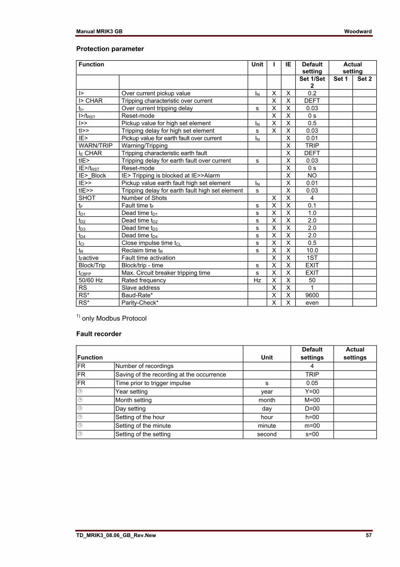
Manual MRIK3 GB Woodward
TD_MRIK3_08.06_GB_Rev.New 57
Protection parameter Function Unit I IE Default
setting Actual setting
Set 1/Set 2
Set 1 Set 2
I> Over current pickup value IN X X 0.2 I> CHAR Tripping characteristic over current X X DEFT tI> Over current tripping delay s X X 0.03 I>/tRST Reset-mode X X 0 s I>> Pickup value for high set element IN X X 0.5 tI>> Tripping delay for high set element s X X 0.03 IE> Pickup value for earth fault over current IN X 0.01 WARN/TRIP Warning/Tripping X TRIP IE CHAR Tripping characteristic earth fault X DEFT tIE> Tripping delay for earth fault over current s X 0.03 IE>/tRST Reset-mode X 0 s IE>_Block IE> Tripping is blocked at IE>>Alarm X NO IE>> Pickup value earth fault high set element IN X 0.01 tIE>> Tripping delay for earth fault high set element s X 0.03 SHOT Number of Shots X X 4 tF Fault time tF s X X 0.1 tD1 Dead time tD1 s X X 1.0 tD2 Dead time tD2 s X X 2.0 tD3 Dead time tD3 s X X 2.0 tD4 Dead time tD4 s X X 2.0 tCI Close impulse time tCL s X X 0.5 tR Reclaim time tR s X X 10.0 tFactive Fault time activation X X 1ST Block/Trip Block/trip - time s X X EXIT tCBFP Max. Circuit breaker tripping time s X X EXIT 50/60 Hz Rated frequency Hz X X 50 RS Slave address X X 1 RS* Baud-Rate* X X 9600 RS* Parity-Check* X X even
1) only Modbus Protocol Fault recorder Default Actual Function Unit settings settings FR Number of recordings 4 FR Saving of the recording at the occurrence TRIP FR Time prior to trigger impulse s 0.05
Year setting year Y=00 Month setting month M=00 Day setting day D=00 Setting of the hour hour h=00 Setting of the minute minute m=00 Setting of the setting second s=00

Woodward Manual MRIK3 GB
58 TD_MRIK3_08.06_GB_Rev.New
Assignment of the blocking function Default setting Actual setting Parameter switch Set 1 Set 2 Set 1 Set 2 Blocking the protection function PR_B
PR_B PR_B
Blocking the trip step TR_B Default setting Actual setting Function Blocking No blocking Blocking No blocking Parameter set Set 1 Set 2 Set 1 Set 2 Set 1 Set 2 Set 1 Set 2 I> X X I>> X X IE> X X IE>> X X tCBFP X X
Assignment of the output relays
Relay function Output relay Display corresponding 1 2 3 4 indication LED I> Alarm X _ 2 _ _ I> Trip-
ping X 1 _ _ _ tI>
I>> Alarm X _ 2 _ _ I>> Trip-
ping X 1 _ _ _ tI>>
I>>FAST
TRIP Trip-ping
X 1 _ _ _ I>> + CB
IE> Alarm X _ 2 _ _ IE> Trip-
ping X 1 _ _ _ tIE>
IE>> Alarm X _ 2 _ _ IE>> Trip-
ping X 1 _ _ _ tIE>>
CBFP Trip-ping
_ _ _ _ CB
AR Switch on
X _ _ _ 4 AR + tCL
AR Unsuc-cessful
X _ _ 3 _ AR + O→I rot

Manual MRIK3 GB Woodward
TD_MRIK3_08.06_GB_Rev.New 59
Assignment of AR functions Function Default setting Actual setting Parameter switch Set 1 Set 2 Set 1 Set 2 Trip after the 1st AR I> TIME TIME I>> TIME TIME IE> TIME TIME IE>> TIME TIME Activation of the 1st AR per I> NO NO I>> YES YES IE> NO NO IE>> NO NO Trip after the 1st AR I> TIME TIME I>> TIME TIME IE> TIME TIME IE>> TIME TIME Activation of the 2nd AR per I> NO NO I>> YES YES IE> NO NO IE>> NO NO Trip after the 2nd AR I> TIME TIME I>> TIME TIME IE> TIME TIME IE>> TIME TIME Activation of the 3rd AR per I> NO NO I>> YES YES IE> NO NO IE>> NO NO Trip after the 3rd AR I> TIME TIME I>> TIME TIME IE> TIME TIME IE>> TIME TIME Activation of the 4th AR per I> NO NO I>> YES YES IE> NO NO IE>> NO NO Trip after 4th AR I> TIME TIME I>> TIME TIME IE> TIME TIME IE>> TIME TIME

Woodward Manual MRIK3 GB
60 TD_MRIK3_08.06_GB_Rev.New
Setting of code jumpers Code jumper J1 J2 J3 Default
setting Actual setting
Default setting
Actual setting
Default setting
Actual setting
Plugged Not plugged X no function no function
Code jumper Low/High-Range for Reset Input Low/High-Range for Blockage Input Default setting Actual setting Default setting Actual setting Low = plugged X X High = not plugged
Code jumper Low/High-Range for
Reset Input Low/High-Range for the
CB-OK-Input Low/high-Range for the
CB-On-Input Default
setting Actual setting
Default setting
Actual setting
Default setting
Actual setting
Low = plugged X X X High = not plugged
This manual is valid for relay software version from Software-Versions No. D01-2.13 Modbus Versions No. D51-1.23
Woodward SEG GmbH & Co. KG Krefelder Weg 47 ⋅ D – 47906 Kempen (Germany)
Postfach 10 07 55 (P.O.Box) ⋅ D – 47884 Kempen (Germany) Phone: +49 (0) 21 52 145 1
Internet
Homepage http://www.woodward-seg.com Documentation http://doc.seg-pp.com
Sales
Phone: +49 (0) 21 52 145 635 ⋅ Telefax: +49 (0) 21 52 145 354 e-mail: [email protected]
Service
Phone: +49 (0) 21 52 145 614 ⋅ Telefax: +49 (0) 21 52 145 455 e-mail: [email protected]