mrfd1 multirheo filter - start: hydac mrfd1 4113517a en-us 2016-08-10.docx 2016-08-10 safety...
TRANSCRIPT

MRFD1 MultiRheo Filter
Installation and Maintenance Instructions English (translation of original instructions)
Keep for future reference.
Document No.: 4113517a

Imprint
MRFD1 en(us) Page 2 / 44
MoWa MRFD1 4113517a en-us 2016-08-10.docx 2016-08-10
Imprint
Publisher and responsible for the content: HYDAC FILTER SYSTEMS GMBH Postfach 1251 66273 Sulzbach / Saarland Germany Phone: +49 6897 509 01 Fax: +49 6897 509 9046 E-mail: [email protected] Homepage: www.hydac.com Court of Registration: Saarbrücken, HRB 17216 Executive director: Mathias Dieter, Dipl.Kfm. Wolfgang Haering
Documentation Representative
Mr. Günter Harge c/o HYDAC International GmbH, Industriegebiet, 66280 Sulzbach / Saar Telephone: +49 6897 509 1511 Fax: +49 6897 509 1394 E-mail: [email protected]
© HYDAC FILTER SYSTEMS GMBH
All rights reserved. No part of this work may be reproduced in any form (print, photocopy or by other means) or processed, duplicated or distributed using electronic systems without the written consent of the publisher. These documents have been created and inspected with the greatest care. However, errors cannot be ruled out completely.

Content
MRFD1 en(us) Page 3 / 44
MoWa MRFD1 4113517a en-us 2016-08-10.docx 2016-08-10
Content
MRFD1 ........................................................................................................... 1
MultiRheo Filter ............................................................................................. 1
Imprint ............................................................................................................ 2
Documentation Representative ................................................................... 2
Content .......................................................................................................... 3
Preface ........................................................................................................... 5
Technical Support ........................................................................................ 5 Product modification .................................................................................... 5 Warranty ...................................................................................................... 5 Using the documentation ............................................................................. 6
Safety information ........................................................................................ 7
Hazard symbols ........................................................................................... 7 Signal words and their meaning in the safety information and instructions .................................................................................................. 8 Structure of the safety information and instructions ..................................... 8 Proper/Designated Use ............................................................................... 9 Improper Use or Use Deviating from Intended Use ................................... 10 Qualifications of personnel / target group .................................................. 11 Wear suitable clothing ............................................................................... 12 Observe regulatory information ................................................................. 12
Unpacking the product ............................................................................... 12
Transporting / storing the product ............................................................ 13
Decoding the name plate ........................................................................... 14
Checking the scope of delivery ................................................................. 15
Product features ......................................................................................... 16
Filter components ....................................................................................... 17
Filter dimensions ........................................................................................ 19
Filter hydraulic diagram ............................................................................. 20
Calculating the pressure loss of the filter housing / filter element ........ 21
Housing p∆ : Pressure loss curve, housing ............................................... 21
Filter element- p∆ : pressure loss calculation, filter element....................... 21 R (Resistance) Factors .............................................................................. 22
Filter material.......................................................................................... 22 Maximum differential pressure at the filter element ................................ 22 Filter elements - Flexmicron P (Premium) .............................................. 22 Filter elements - Flexmicron S (Standard) .............................................. 23

Content
MRFD1 en(us) Page 4 / 44
MoWa MRFD1 4113517a en-us 2016-08-10.docx 2016-08-10
Filter elements - Flexmicron E (Economy) ............................................. 23
Mounting the filter housing ........................................................................ 24
Notes on pipes and hoses ......................................................................... 25
Filter housing switchover .......................................................................... 26
Starting up the filter .................................................................................... 28
Observe the clogging indicator .................................................................. 29 Viewing and resetting the optical clogging indicator ............................... 29 Observing electrical clogging indicator ................................................... 29
Performing maintenance ........................................................................... 30
Changing filter element .............................................................................. 30
Spare parts list ............................................................................................ 35
Decommissioning the filter ........................................................................ 37
Stopping the Filter ...................................................................................... 37
Disposing of the Filter ................................................................................ 37
Customer Service / Service ........................................................................ 37
Technical data ............................................................................................. 38
Model code .................................................................................................. 39
Index ............................................................................................................ 40

Preface
MRFD1 en(us) Page 5 / 44
MoWa MRFD1 4113517a en-us 2016-08-10.docx 2016-08-10
Preface
These operating instructions were made to the best of our knowledge. Nevertheless and despite the greatest care, it cannot be excluded that mistakes could have crept in. Therefore please understand that, in the absence of any provisions to the contrary hereinafter, our warranty and liability – for any legal reasons whatsoever – are excluded in respect of the information in these operating instructions. In particular, we shall not be liable for lost profit or other financial loss. This exclusion of liability does not apply in cases of intent and gross negligence. Moreover, it does not apply to defects which have been deceitfully concealed or whose absence has been guaranteed, nor in cases of culpable harm to life, physical injury and damage to health. If we negligently breach any material contractual obligation, our liability shall be limited to foreseeable damage. Claims due to Product Liability shall remain unaffected.
Technical Support Contact our technical sales department if you have any questions on our product. When contacting us, please always include the model code, serial no. and part no. of the product: Fax: +49 6897 509 9046 E-mail: [email protected]
Product modification We would like to point out that changes to the product (e.g. purchasing additional options, etc.) may mean that the information in the operating instructions is no longer applicable or adequate. After modification or repair work that affects the safety of the product has been carried out on components, the product may not be returned to operation until it has been checked and released by a HYDAC technician. Please notify us immediately of any modifications made to the product whether by you or a third party.
Warranty For the warranty provided by us, please refer to the General Terms of Sale and Delivery of HYDAC FILTER SYSTEMS GMBH. You will find these under www.hydac.com -> General Terms and Conditions.

Preface
MRFD1 en(us) Page 6 / 44
MoWa MRFD1 4113517a en-us 2016-08-10.docx 2016-08-10
Using the documentation
Note that the method described for locating specific information does not release you from your responsibility of carefully reading all these instructions prior to starting the unit up for the first time and at regular intervals in the future.
What do I want to know? I determine which topic I am looking for. WHERE can I find the information I’m looking for? The documentation has a table of contents at the beginning. There, I select the chapter I'm looking for and the corresponding page number.
deHYDAC Filtertechnik GmbHBeWa 123456a de
Seite x
Produkt / Kapitel
200x-xx-xx
The documentation number with its index enables you to order another copy of the operating and maintenance instructions. The index is incremented every time the manual is revised or changed.
Chapter description
Page number Edition date
Document language
Documentation No. with Index /
File name

Safety information
MRFD1 en(us) Page 7 / 44
MoWa MRFD1 4113517a en-us 2016-08-10.docx 2016-08-10
Safety information
The filter was built according to the statutory provisions valid at the time of delivery and satisfies current safety requirements. Any residual hazards are indicated by safety information and instructions and are described in the operating instructions. Observe all safety and warning instructions attached to the filter. They must always be complete and legible. Do not operate the filter unless all the safety devices are present. Secure the hazardous areas which may arise between the filter and other equipment. Maintain the unit inspection intervals prescribed by law. Document the results in an inspection certificate and keep it until the next inspection.
Hazard symbols These symbols are listed for all safety information and instructions in these operating instructions which indicate particular hazards to persons, property or the environment. Observe these instructions and act with particular caution in such cases. Pass all safety information and instructions on to other users.
General hazard
Danger due to operating pressure
Risk of burns due to hot surfaces

Safety information
MRFD1 en(us) Page 8 / 44
MoWa MRFD1 4113517a en-us 2016-08-10.docx 2016-08-10
Signal words and their meaning in the safety information and instructions The following signal words are to be found in these instructions.
DANGER DANGER – The signal word indicates a hazardous situation with a high level of risk, which, if not avoided, will result lethal or serious injury.
WARNING WARNING – The signal word indicates a hazardous situation with a medium level of risk, which, if not avoided, can result lethal or serious injury.
CAUTION CAUTION – The signal word indicates a hazardous situation with a low level of risk, which, if not avoided, can result in minor or moderate injury.
NOTICE NOTICE – The signal word indicates a hazardous situation with a high level of risk, which, if not avoided, will result in damage to property.
Structure of the safety information and instructions All warning instructions in this manual are highlighted with pictograms and signal words. The pictogram and the signal word indicate the severity of the danger. Warning instructions listed before an activity are laid out as follows:
HAZARD SYMBOL
SIGNAL WORD Type and source of danger
Consequence of the danger
► Measures to avert danger

Safety information
MRFD1 en(us) Page 9 / 44
MoWa MRFD1 4113517a en-us 2016-08-10.docx 2016-08-10
Proper/Designated Use Only use the filter for the application described in the following. The MultiRheo Filter (MRF) is a stationary filtration unit used for the full-flow and bypass filtration of low-viscosity fluids. The filter is intended hold Flex Micron filter elements. Making sure that the pressure equipment is operated within the permitted usage ranges is to be guaranteed by suitable monitoring and safety equipment. Please see: Pressure Equipment Directive (2014/68/EU).
NOTICE
Impermissible operating media/conditions
The filter housing will be damaged.
► The filter may only be used in connection with mineral oils, mineral-oil-based raffinates or coolants.
Proper or designated use of the product extends to the following:
• Observing all instructions contained in the instruction manual.
• Adhering to maintenance work.
• Operation only reciprocal, this means the switching lever always has to be in an end position.

Safety information
MRFD1 en(us) Page 10 / 44
MoWa MRFD1 4113517a en-us 2016-08-10.docx 2016-08-10
Improper Use or Use Deviating from Intended Use Any use extending beyond or deviating therefrom shall not be considered intended use. HYDAC Filter Systems GmbH will assume no liability for any damage resulting from such use. The owner alone, shall assume any and all associated risk Improper use or deviating from intended use may result in hazards and/or will damage the filter. Examples of improper use:
• Operation with switching lever in an interim position
• Operation with an impermissible fluid.
• Operation under non-approved operational conditions.
• Operation when the safety devices are defective.
• Modifications to the filter made by the user or purchaser.
• Inadequate monitoring of parts that are subject to wear and tear
• Improperly performed repair work.

Safety information
MRFD1 en(us) Page 11 / 44
MoWa MRFD1 4113517a en-us 2016-08-10.docx 2016-08-10
Qualifications of personnel / target group Persons who work on the power unit must be aware of the associated hazards when using the power unit. Operating and specialist personnel must have read and understood the operating instructions, in particular the safety information and instructions, and applicable regulations before beginning work. The operating instructions and applicable regulations are to kept so they are accessible for operating and specialist personnel. These operating instructions are intended for: Auxiliary personnel: such persons have no specialized knowledge and perform work as instructed. Operating personnel: such persons have been instructed in power unit operation and are aware of potential hazards due to improper use. Specialist personnel: such persons have corresponding specialist training and several years' work experience. They are able to assess and perform the work assigned to them, they are also able to recognize potential hazards. Activity Person Knowledge
Transport / storage Auxiliary personnel
No specialist knowledge required
Startup operation Operations control
Operating Personnel
Product-specific knowledge Knowledge about how to handle operating media.
troubleshooting, maintenance, decommissioning, Disassembly
Specialist personnel
Safe handling/use of tools Product-specific knowledge
Disposal Specialist personnel
Proper and environmentally-friendly disposal of materials and substances Decontamination of contaminants Knowledge about reuse

Unpacking the product
MRFD1 en(us) Page 12 / 44
MoWa MRFD1 4113517a en-us 2016-08-10.docx 2016-08-10
Wear suitable clothing Loose-fitting clothing increases the risk of getting caught on protruding parts. You can be severely injured or killed.
• Wear close-fitting clothing.
• Do not wear any rings, chains or any other jewelry.
• Wear work safety shoes.
• Wear gloves.
• Observe the information relating to personal protection equipment in the safety data sheet of the operating fluid.
Observe regulatory information Observe the following regulatory information and guidelines:
• Legal and local regulations for accident prevention
• Legal and local regulations for environmental protection
• Country-specific regulations, organization-specific regulations
Unpacking the product
Prior to delivery, the product is function- and leak-tested in the factory. When unpacking the product, check it for damage in transit.

Transporting / storing the product
MRFD1 en(us) Page 13 / 44
MoWa MRFD1 4113517a en-us 2016-08-10.docx 2016-08-10
Transporting / storing the product
Remove the filter element and completely discharge the filter housing before transport/storage. Close all connections. Permitted storage temperature range
See chapter “Technical data“, page 38.
Permitted air humidity See chapter “Technical data“, page 38.
Air Clean, salt-free air, not near oxidizing substances (danger of rust film).
Storage duration Indefinite. After a storage period of greater than 2 years, replace all seals before commissioning.
Storage position Lying on its side

Decoding the name plate
MRFD1 en(us) Page 14 / 44
MoWa MRFD1 4113517a en-us 2016-08-10.docx 2016-08-10
Decoding the name plate
For identification details of the filter housing, see the name plate.
Item -> Description
(1) -> The type label of the filter housing
(2) -> Model code; for details, see page 39 The following information can be found on the name plate of the unit: Row -> Description
Part No.: -> Part number
S/N: -> Serial number / year of production
Pressure max.: -> Maximum permitted operating pressure
Weight: -> Voltage / power supply
Seals: -> Frequency
Temp. Oil: -> Permitted fluid temperature range
Temp. amb.: -> Permitted ambient temperature range
Volume: -> Fluid volume in unit

Checking the scope of delivery
MRFD1 en(us) Page 15 / 44
MoWa MRFD1 4113517a en-us 2016-08-10.docx 2016-08-10
Checking the scope of delivery
Upon receiving the filter, check it for any damage in transit. Do not put the filter into operation unless it is in perfect condition. Report any damage to the forwarding agent immediately. The filter is factory-tested for leakage and proper functioning and is properly packed. The connections are all sealed with plastic plugs to prevent the intrusion of contaminants into the filter during transport. The following items are supplied:
Qty Description 1 MultiRheo Filter MRFD1 (without filter element)
1 Installation and Maintenance Instructions (this document)

Product features
MRFD1 en(us) Page 16 / 44
MoWa MRFD1 4113517a en-us 2016-08-10.docx 2016-08-10
Product features
The MultiRheo Filter is a stationary filtration unit used for the full-flow and bypass filtration of low-viscosity fluids. The MRF is used for the separation of particles 100 µm to 1 µm (absolute) in size.

Filter components
MRFD1 en(us) Page 17 / 44
MoWa MRFD1 4113517a en-us 2016-08-10.docx 2016-08-10
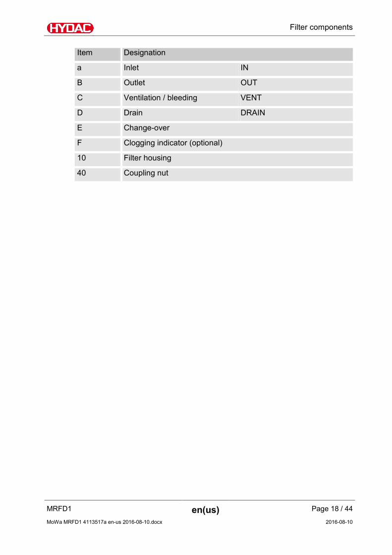
Filter components
The filter housing has the following components:
Filter components
MRFD1 en(us) Page 18 / 44
MoWa MRFD1 4113517a en-us 2016-08-10.docx 2016-08-10
Item Designation
a Inlet IN
B Outlet OUT
C Ventilation / bleeding VENT
D Drain DRAIN
E Change-over
F Clogging indicator (optional)
10 Filter housing
40 Coupling nut

Filter dimensions
MRFD1 en(us) Page 19 / 44
MoWa MRFD1 4113517a en-us 2016-08-10.docx 2016-08-10
Filter dimensions
The filter housing has the following dimensions:
Filter Size Length A 10“ 348 mm 20“ 602 mm 30“ 856 mm 40“ 1110 mm

Filter hydraulic diagram
MRFD1 en(us) Page 20 / 44
MoWa MRFD1 4113517a en-us 2016-08-10.docx 2016-08-10
Filter hydraulic diagram
The filter has the following hydraulic diagram:
C C
D D
A
B
F
a = Inlet IN B = Outlet OUT C = Ventilation / bleeding VENT D = Drain DRAIN E = Change-over valve F = Clogging indicator (optional)

Calculating the pressure loss of the filter housing / filter element
MRFD1 en(us) Page 21 / 44
MoWa MRFD1 4113517a en-us 2016-08-10.docx 2016-08-10
Calculating the pressure loss of the filter housing / filter element
The total pressure of the filters at a specific flow rate is comprised of the housing p∆ and the filter element p∆ . The pressure loss of the housing can be determined using the following pressure loss curve. The pressure loss of the elements is calculated on the basis of the R factors.
Housing p∆ : Pressure loss curve, housing
Diff
eren
tial p
ress
ure
(bar
)
Flow rate (l/min)
The upper housing curve holds for mineral oil with a density of 0.86 kg/dm³ and a kinematics viscosity of 30 mm²/s. The lower housing curve holds for water at 20°C. For turbulent flow, the differential pressure will change proportionally to the density; for laminar flow, it will change proportionally to the density and viscosity. The flow velocity should not exceed 3 m/s at the filter inlet for oil and 4 m/s for water.
Filter element- p∆ : pressure loss calculation, filter element The following calculation is based on clean filter elements:
1000)(min)/()/²()(
××××
=∆inchLn
lQsmmVRbarp
R = R Factor V = viscosity (mm²/s) Q = flow rate (l/min) N = Numbers of elements L = element length (inch)

Calculating the pressure loss of the filter housing / filter element
MRFD1 en(us) Page 22 / 44
MoWa MRFD1 4113517a en-us 2016-08-10.docx 2016-08-10
R (Resistance) Factors Filter material
Abbreviation = Designation
PA = Polyamide
PP = Polypropylene
PES = Polyester
GF = Glass fiber
Maximum differential pressure at the filter element The maximum differential pressure Δpmax and the permitted temperature at the filter element are:
Filter material Fluid temperature PP PA PES
-10 … 30°C 4 bar 7 bar 8 bar
-10 … 60°C 2 bar 5.5 bar 6.5 bar
-10 … 100°C - 3.5 bar 5 bar
Filter elements - Flexmicron P (Premium) Aqueous fluids Oils
Filtration rating PES* PES* GF**
1 µm 32.0 10.4 5.4
3 µm 24.0 7.5 -
5 µm 18.0 4.4 4.3
10 µm 17.0 1.8 3.2
20 µm 15.0 1.8 -
30 µm 14.0 0.9 -
40 µm 14.0 0.9 -
* ß > 5,000 ** ß > 20,000

Calculating the pressure loss of the filter housing / filter element
MRFD1 en(us) Page 23 / 44
MoWa MRFD1 4113517a en-us 2016-08-10.docx 2016-08-10
Filter elements - Flexmicron S (Standard) Aqueous fluids
Filtration rating PA PP
1 µm 274 321
3 µm 116 186
5 µm 42 132
10 µm 15 99
20 µm 11 54
30 µm 6 16
40 µm 3.8 12
50 µm 1.9 10
70 µm 1.1 8
90 µm 0.6 8
Filter elements - Flexmicron E (Economy) Aqueous fluids
Filtration rating PP
1 µm 37
3 µm 29
5 µm 20
10 µm 11
20 µm 8
30 µm 6.8
40 µm 5.4
50 µm 4.2
70 µm 3.1

Mounting the filter housing
MRFD1 en(us) Page 24 / 44
MoWa MRFD1 4113517a en-us 2016-08-10.docx 2016-08-10
Mounting the filter housing
The filter housing is designed for horizontal or vertical installation in a pipeline or hose line with flange connection, SAE1" (3000 PSI). Use both rear side fastening threads M12, 15 mm deep.
Before installation, coat the connector threads with a lubricant containing a slip additive (MoS2). This prevents damage to the connector threads during installation.
Make sure that there is sufficient space below the filter housing to replace the filter element.

Mounting the filter housing
MRFD1 en(us) Page 25 / 44
MoWa MRFD1 4113517a en-us 2016-08-10.docx 2016-08-10
Notes on pipes and hoses In order to keep the pressure loss as low as possible, use as few threaded connections as possible. The pressure loss in a hydraulic line depends upon:
• Flow rate
• Kinematic viscosity
• Pipe dimensions
• Fluid density The pressure loss can be estimated for hydraulic oils as follows:
Δp ≈ 6.8 * L / d4 * Q * V * D Δp = Pressure differential in [bar]
L = Pipe length [m]
d = Internal pipe diameter [mm]
Q = Flow rate [l/min]
V = Kinematic viscosity [mm²/s]
D = Density [kg/dm³] Mineral oil-based hydraulic fluid has a density of ≈ 0.9 kg/cm³.
This formula applies to straight pipe runs and hydraulic oils. Additional threaded connections and pipe bends increase the pressure differential. Keep the height difference between the filter housing and the oil level in the tank as low as possible. Take note that hoses must be suitable for pressures of at least -0.5 bar. Constrictions in the connections and lines should be avoided. This could compromise suction output and cause cavitation . Take note that the nominal size of the connected hoses/piping must be at least as large as the inlet port sizes. Make sure that no stresses or vibrations are transmitted to the filter housing. Use hoses or expansion joints if necessary.

Filter housing switchover
MRFD1 en(us) Page 26 / 44
MoWa MRFD1 4113517a en-us 2016-08-10.docx 2016-08-10
Filter housing switchover
WARNING Change-over valve in interim position
Danger of bodily injury
► Always operate the filter with the change-over valve in the end position.
CAUTION
Pressure surge during rapid change-over
The filter/filter element will be damaged
► Move the change-over valve slowly from one position to the other to prevent pressure surges onto the filter housing/filter element.

Filter housing switchover
MRFD1 en(us) Page 27 / 44
MoWa MRFD1 4113517a en-us 2016-08-10.docx 2016-08-10
Switch the flow rate on the change-over valve from the active to the passive filter housing. To do this, move the change-over valve from one end position to the other.
Active
filter housing Passive
filter housing Passive
filter housing Active
filter housing

Starting up the filter
MRFD1 en(us) Page 28 / 44
MoWa MRFD1 4113517a en-us 2016-08-10.docx 2016-08-10
Starting up the filter
The filter housing is supplied ex works without a built-in filter element. Prior to commissioning, insert the filter element into the filter housing. Proceed as described from page 30. Observe the following points during operation:
• permissible operating temperature
• permissible operating pressure
• permissible differential pressure on the filter element, see clogging indicator

Starting up the filter
MRFD1 en(us) Page 29 / 44
MoWa MRFD1 4113517a en-us 2016-08-10.docx 2016-08-10
Observe the clogging indicator The filter housing is fitted with different clogging indicators depending on the version. Please observe the clogging indicators, as described in the following.
Viewing and resetting the optical clogging indicator The filter housing is equipped with an optical clogging indicator for monitoring the contamination of the filter element. When the clogging indicator is red (1), change the filter element (2). Reset the clogging indicator by pressing the reset button (3).
Observing electrical clogging indicator With the electrical clogging indicators, an electrical signal is emitted when the filter element is being changed. Change the filter element as soon as the clogging indicator emits the electrical signal.

Performing maintenance
MRFD1 en(us) Page 30 / 44
MoWa MRFD1 4113517a en-us 2016-08-10.docx 2016-08-10
Performing maintenance
WARNING Hydraulic systems are under pressure
Danger of bodily injury
► The hydraulic system must be depressurized before performing any work on the hydraulic system.
► Change the filter element only on the passive filter housing.
Changing filter element To change the filter element on the passive filter housing, proceed as follows:
1.
Change the filter element only on the passive filter housing. Note the change-over valve and define the passive filter housing. Depressurize the filter housing. Unscrew the breather screw (C) in a counterclockwise direction.

Performing maintenance
MRFD1 en(us) Page 31 / 44
MoWa MRFD1 4113517a en-us 2016-08-10.docx 2016-08-10
2. To empty the filter housing, carefully unscrew the drain screw plug (1) at the bottom end of the filter housing in a clockwise direction using a 6 mm Allen
wrench . Collect the escaping fluid with a suitable container (2).
3. Loosen the coupling nut (1) by turning it in
a clockwise direction and then remove the filter bowl (2).
Use a strap wrench to remove the coupling nuts.

Performing maintenance
MRFD1 en(us) Page 32 / 44
MoWa MRFD1 4113517a en-us 2016-08-10.docx 2016-08-10
4. Remove the used filter element from the element mount and dispose of it properly.
5. Clean the sealing surfaces on the filter
head and filter bowl.
6. Clean the sealing surface on the filter
head. Check the O ring for visible signs of damage and, if necessary, replace it. Wet the O ring with hydraulic fluid and insert it.
7. For easy installation of the filter element, wet the O-ring on the filter element with the operating medium.

Performing maintenance
MRFD1 en(us) Page 33 / 44
MoWa MRFD1 4113517a en-us 2016-08-10.docx 2016-08-10
8. Carefully press the new filter element into the element mount by applying slight pressure, pressing it upwards and screwing it in.
Do not use a hammer, etc.
9. (1) Before screwing the union nut back on,
apply lubricant to it. Recommended lubricant for stainless steel unions -> lubricant containing a slip additive (MoS2) HYDAC article no. 3066287 (2) Screw the filter bowl over the coupling nut onto the filter head in a counterclockwise direction. When doing this, screw the union nut hand tight only.
10. Screw in the breather screw (C) by hand
tighten it with an Allen wrench in a clockwise direction.

Performing maintenance
MRFD1 en(us) Page 34 / 44
MoWa MRFD1 4113517a en-us 2016-08-10.docx 2016-08-10
10. The passive filter housing is ready for operation.
11. Check the filter housing for leaks during operation.

Spare parts list
MRFD1 en(us) Page 35 / 44
MoWa MRFD1 4113517a en-us 2016-08-10.docx 2016-08-10
Spare parts list
To ensure safe and reliable operation of the filter, use only original spare parts and accessories. When ordering parts make sure to always indicate the unit designation (cf. name plate) and the serial number.

Spare parts list
MRFD1 en(us) Page 36 / 44
MoWa MRFD1 4113517a en-us 2016-08-10.docx 2016-08-10
Item Designation p/no. Qty
10“ 20“ 30“ 40“
10 Filter bowl 10“ 3204371 2 - - - 10 Filter bowl 20“ 3204372 - 2 - - 10 Filter bowl 30“ 3204373 - - 2 - 10 Filter bowl 40“ 3204374 - - - 2 20 Filter head * 1 1 1 1 30 O-ring FKM 637585 2 2 2 2 40 Coupling nut 545557 2 2 2 2 100 Screw plug FKM 6073033 4 4 4 4 140 Air bleed plug [Air
bleed] 545033 1 1 1 1
141 profile seal ring FKM 413429 1 1 1 1 142 O-ring FKM 610433 1 1 1 1 150 Filter element * 2 2 2 2 - Clogging indicator * 1 1 1 1 - Lubricant containing a
slip additive (MoS2) 3066287 - - - -
*) available on request

Decommissioning the filter
MRFD1 en(us) Page 37 / 44
MoWa MRFD1 4113517a en-us 2016-08-10.docx 2016-08-10
Decommissioning the filter
Drain the filter completely, including all of its components, before decommissioning. Disassemble the hydraulic and electrical connections. Thoroughly clean all components.
Stopping the Filter
See chapter "Decommissioning the filter".
Disposing of the Filter
After dismantling the filter and separating the various materials, dispose of the unit in an environmentally friendly manner.
Customer Service / Service
Regular inspection and maintenance work is indispensable for ensuring trouble-free operation and long service life for your filter. HYDAC SERVICE GMBH Friedrichsthaler Str. 15A, Werk 13 66540 Neunkirchen-Heinitz Germany Phone: +49 6897 509 883 Fax: +49 6897 509 324 E-mail: [email protected]

Technical data
MRFD1 en(us) Page 38 / 44
MoWa MRFD1 4113517a en-us 2016-08-10.docx 2016-08-10
Technical data
MRF1 … Number of filter elements 1
Operating pressure, maximum 40 bar
Material of sealings FKM
Hydraulic connection SAE1“ (PSI3000)
Permitted fluid temperature range -10 … 90°C
Permitted storage temperature range
5 … 30°C
Installation size in inches 10“ 20“ 30“ 40“
Filter housing volume in liters 2x 1.1 2x2.1 2x3 2x 4
Weight when empty in kg ≈ 10 ≈ 13 ≈ 16 ≈ 18
Change-over valve material 1.4581 / 1.4571 / 2.0401
Filter bowl material 1.4581 / 1.4571

Model code
MRFD1 en(us) Page 39 / 44
MoWa MRFD1 4113517a en-us 2016-08-10.docx 2016-08-10
Model code
MRFD 1 E / 1 Y 40 40 N 0 0 Filter type MRFD = Changeover MultiRheo Filter Filter Size 1 = Ø ≈ 76 mm Housing material E = Stainless Number of elements 1 = 1 Filter element Connection type Y = SAE 1“ Element construction length 10 = 10“ 20 = 20“ 30 = 30“ 40 = 40“ Pressure range 10 = 10 bar 25 = 25 bar 40 = 40 bar Material of sealings F = FKM (Viton) Clogging indicator for housing material E C12 = Differential pressure indicator, electrical (PVD 2 C.0)
D13 = Differential pressure indicator, visual/electrical (VM2D.0/-L110)
D17 = Differential pressure indicator, visual/electrical (PVD2D.0/-L220)
D18 = Differential pressure indicator, visual/electrical (PVD2D.0/-L24)
D32 = Differential pressure indicator, visual/electrical (PVL2GW.0/-V-113)
D33 = Differential pressure indicator, visual/electrical (PVL2GW.0/-V-111-16-)
Modification code

Index
MRFD1 en(us) Page 40 / 44
MoWa MRFD1 4113517a en-us 2016-08-10.docx 2016-08-10
Index
A accident prevention ......................................................... 12 ambient temperature ....................................................... 14 Auxiliary personnel ........................................................... 11
B bleeding ...................................................................... 18, 20
C care................................................................................. 2, 5 change-over ......................................................... 26, 27, 30 Change-over ................................................... 18, 20, 26, 38 Clogging indicator ........................................... 18, 20, 36, 39 Connection ....................................................................... 39 Content .............................................................................. 3
D Density ............................................................................. 25 Description ................................................................. 14, 15 Differential pressure .................................................. 21, 39 Differential pressure indicator ......................................... 39 Disposal ............................................................................ 11 Documentation Representative ......................................... 2 DRAIN ......................................................................... 18, 20
F Filter .. 1, 9, 10, 15, 16, 17, 18, 19, 20, 21, 22, 23, 26, 36, 37,
38, 39 Filter element ............................................ 21, 22, 23, 36, 39 Filter housing ........................................................ 18, 26, 38 Filter housing volume ....................................................... 38 filtration ....................................................................... 9, 16 Filtration ..................................................................... 22, 23 Flexmicron .................................................................. 22, 23 Flow rate .................................................................... 21, 25 Fluid temperature ............................................................ 22
H Hazard symbol ................................................................ 7, 8 Hydraulic connection ....................................................... 38
I Imprint................................................................................ 2 IN 18, 20 Inlet ............................................................................ 18, 20 installation .................................................................. 24, 32 Internal pipe diameter ..................................................... 25
M Maintenance ................................................................. 1, 15 Material of sealings ..................................................... 38, 39 Measures ............................................................................ 8 Mineral oil ......................................................................... 25 Model code ................................................................. 14, 39
O operating ...................................5, 6, 7, 9, 11, 12, 14, 28, 32 operating temperature ..................................................... 28 Operation ...................................................................... 9, 10 Operations control ............................................................ 11 OUT ............................................................................. 18, 20 Outlet .......................................................................... 18, 20
P Pressure differential ......................................................... 25 Pressure Equipment Directive ............................................ 9 Pressure range .................................................................. 39 Proper/Designated Use....................................................... 9 Publisher ............................................................................. 2
S SAE .................................................................................... 39 select ................................................................................... 6 Service .............................................................................. 37 Signal word ......................................................................... 8 signal words ........................................................................ 8 Size .............................................................................. 19, 39 Spare part ......................................................................... 35 Spare parts ........................................................................ 35 Spare parts list .................................................................. 35 Specialist personnel .......................................................... 11 storing ............................................................................... 13
T Transport .......................................................................... 11 troubleshooting ................................................................ 11
V VENT ........................................................................... 18, 20
W Weight ........................................................................ 14, 38

Notes

Notes


HYDAC FILTER SYSTEMS GMBH Industriegebiet Postfach 1251 66280 Sulzbach/Saar 66273 Sulzbach/Saar Germany Germany Phone: +49 (0) 6897 509 01 Central Fax: +49 (0) 6897 509 846 (Technical Department) Fax: +49 (0) 6897 509 577 Sales Department Internet: www.hydac.com E-mail: [email protected]