mr556a1 - cloud object storage | store & retrieve data ... hk free floating rail system (ffrs)...
TRANSCRIPT

MR556A1OPERATOR’S MANUAL
Covering MR556A1 5.56 x 45 mm Rifle &
MR556A1 Upper Receiver Kit

WARNING: A firearm has the capability of taking your life or the life of someone else! Be extremely careful with your firearm. An accident can occur at anytime and is almost always the result of not following basic safety rules.
© Heckler & Koch, 1/11, 4/11, 4/12, Revised July 2013All rights reserved
Heckler & Koch5675 Transport BoulevardColumbus, Georgia 31907
Tel: (706) 568-1906 • Fax: (706) 568-9151Global Website: www.heckler-koch.com • American Website: www.hk-usa.com
Every attempt has been made to ensure the accuracy of this information, however errors or changes may occur. Specifications and models subject to change without notice.
SAFETY PRECAUTIONS
CAUTION: Read these safety rules before handling the firearm!
Read this operators manual before handling your firearm. The following safety rules are placed in this manual by HK as an important reminder that firearms safety is your responsibility. If handled improperly firearms can be dangerous and can potentially cause damage to property, serious injury, or death.
1. Never point a firearm at anyone, or in any direction other than a SAFE direction, i.e. downrange.
2. Treat all firearms as if they are always loaded.3. Keep your finger off the trigger and outside of the trigger guard until your sights are
aligned on the target.4. Keep your finger off the trigger and outside of the trigger guard while loading or
unloading the firearm.5. Keep your finger off the trigger and outside of the trigger guard while slinging the
firearm or while carrying it.6. Be sure of your target and the back stop beyond.7. Never give a firearm to or take a firearm from anyone unless the action is open and
the magazine and/or chamber are free of any ammunition or brass.8. Be sure that the ammunition you are using is factory loaded, is of the correct caliber
for the firearm in which it is to be used, and that it is not damaged in any way.9. Before firing, remove the magazine from the firearm, lock the bolt open, make
sure the chamber is clear of any ammunition or brass, and check the barrel of the unloaded firearm for any possible obstructions.
10. Before firing any firearm that is unfamiliar to you, make sure that you understand exactly how it functions. A lack of familiarity with the firearm can result in serious accidents. Attend a certified training course on any firearm which you intend to use or with which you are not sufficiently familiar.
11. Always wear hearing and eye protection when using your firearm.12. Keep all body parts, particularly the hands and fingers, away from the muzzle to avoid
injury or burns.13. Be sure that parts of the hand do not touch or interfere with the action. 14. Firearms should be stored separately from ammunition and beyond the reach of
children, and/or any untrained individuals.15. Avoid the use of any alcoholic beverages or drugs before and during the use of any
firearm.16. Discharging firearms in poorly ventilated areas, cleaning firearms, or handling
ammunition may result in exposure to lead, a substance known to be associated with birth defects, reproductive harm, and other serious injury. Have adequate ventilation at all times. Wash hands thoroughly after exposure.
17. To make the firearm safe, one must ensure the chambered round is removed during the clearing procedure. Removal of the rifle’s magazine does not remove the chambered round. This can only be done with the rearward movement of the bolt after the magazine is removed.
STOP! KNOW HOW TO CLEAR THIS FIREARM BEFORE ATTEMPTING TO OPERATE. SEE PAGE 5
Covering the MR556A1 5.56 x 45 mm Rifle and MR556A1 Upper Receiver Kit
MR556A1OPERATOR’S MANUAL

4 5
TABLE OF CONTENTS
Safety Precautions ................................................................... Inside Cover
Clearing ......................................................................................................5
Section 1 Introduction ................................................................................................6
Section 2 Nomenclature and Description .................................................................7
Section 3 Function and Op er a tion ..........................................................................12
Section 4 Sights, Sight Adjustment and Aiming ......................................................15
Section 5 Ammunition ..............................................................................................19
Section 6 Instructions for Use ...................................................................................20
Loading the Magazine .............................................................................20
Loading the Rifle ......................................................................................20
Firing the Rifle ..........................................................................................22
Unloading the Rifle ..................................................................................23
Section 7 Disassembly and Assembly ......................................................................24
Disassembly of the MR556A1 ..................................................................24
Assembly of the MR556A1 .......................................................................30
Function Check .......................................................................................37
Magazine Disassembly .............................................................................38
Magazine Assembly .................................................................................40
Section 8 Cleaning and Main te nance .....................................................................42
Lubrication ...............................................................................................43
Section 9 Troubleshooting Prob lems and Re pair ....................................................46
Section 10 Exploded Diagram and Parts List ............................................................48
Section 11 Specifications ...........................................................................................51
Warranty Registration ...............................................................................51
Section 12 MR556A1 Upper Receiver Kit Supplement ..............................................52
Firearms Service Record ....................................................................................................56

6 7
SECTION 1 — INTRODUCTION
A direct descendent of the HK416, the MR556A1 is a semi-automatic rifle developed by Heckler & Koch as a premium level commercial/civilian firearm with match rifle capability. Like the HK416, the MR556A1 is a major product improvement over conventional AR-type carbines and rifles. The MR556A1 uses the HK proprietary gas piston operating system, employing a piston and a solid operating “pusher” rod in place of the gas tube normally found in AR15/M16/M4-style firearms.
This method of operation virtually eliminates malfunctions that are common to direct impingement gas systems since hot carbon fouling and waste gases do not enter the receiver area. This is the same key feature critical to the success of the HK416 rifles used by leading military and law enforcement customers. The MR556A1 is manufactured in the USA using American and German made components. The MR556A1 uses many of the same assemblies and accessories originally developed for the HK416 including the HK free-floating four-quadrant rail system.
The HK Free Floating Rail System (FFRS) handguard has four MIL-STD-1913 Picatinny rails and allows all current accessories, sights, lights, and aimers used on M4/M16-type arms to be fitted to the MR Series. The HK rail system can be installed and removed with simple tools and returns to zero when reinstalled. The MR556A1 also has a Picantinny rail machined into the top of its upper receiver for mounting optics and mechanical sights.
Unlike earlier prototypes, major subassemblies, including the MR556A1 upper receiver/barrel assembly, are fully interchangeable with other high quality AR-style firearms. MR556A1 upper receiver kits can be used to retrofit competing legacy AR systems.
Like the famous HK416, the MR556A1 uses a German-made barrel produced by Heckler & Koch’s famous cold hammer forging process. The highest quality steel is used in this unique manufacturing process producing a barrel that provides superior accuracy and long service life. But unlike the HK416, the MR556A1 does not use a chrome-lined barrel. Chrome-lining can sometimes mask bore imperfections and negatively affect accuracy. For the new series of Heckler & Koch semi-automatic MR rifles, HK designers and engineers believe best accuracy comes with an unlined bore.
Used with the HK Free Floating Rail System, the barrel does not touch the handguard, ensuring the barrel is truly free-floating for maximum accuracy. The unchromed barrel has an internal profile of 6 lands and grooves with a 1 in 7 inch (178 mm) twist. It is also moderately “swagged” with a slightly smaller internal diameter at the muzzle end than the chamber end. This feature has a positive effect on bullet accuracy and velocity. The thick, heavy contour 16.5-inch MR556A1 barrel also contributes to its excellent accuracy.
A precise enhanced two-stage trigger adds significantly to the accuracy of the MR5556A1 and an extended latch charging handle makes operating the rifle with a telescopic sight easier. The retractable buttstock can be locked into a solid, non-moving position by tightening an Allen screw in the bottom of the stock. Special target rifle takedown pins ensure the upper and lower receivers are firmly mated for accurate performance.
Designed to function with a wide variety of high quality 5.56 x 45 mm ammunition, the MR556A1 uses a C.I.P. dimensioned chamber (a chamber with dimensions specified by the Commission Internationale Permanente). The MR556A1 also functions reliably with most quality Caliber .223 Remington ammunition. The MR556A1 is being produced with the same commitment to quality as German-made HK firearms. By using joint U.S./German manufacturing, Heckler & Koch leverages the relative strengths of two continents to make the preeminent AR-type firearm, combining the design innovations of the USA and Germany into one new product.
SECTION 2 — NOMENCLATURE & DESCRIPTION
Fig. 1 – MR556A1 Right and Left Views
1. Compensator – Bird cage style flash hider is screwed to the end of the barrel and helps compensate for muzzle rise during firing.
2. Gas Block – Directs the expended gas from the gas port hole in the barrel and pushes the piston rearward, pushing the piston rod and bolt carrier rearward (defined in more detail in the cycle of operation). Contains an attachment point for the optional HK folding front sight.
3. Free Floating Rail System (FFRS) – The HK FFRS is a free-floating detachable rail system with four-quadant MIL-STD-1913 (Picatinny) rails that can mount a variety of accessories including sights, scopes, a forward grip, lights, laser aimers, bipods, and sling hardware. The bore sight alignment of aiming devices is repeatable (no re-zeroing required) when the Free Floating Rail System is removed and reinstalled on the firearm. The Free Floating Rail System is removed and reinstalled with a 5 mm Allen wrench.
4. Upper Receiver – The upper receiver is a flat-top design with an integral MIL-STD-1913 (Picatinny) rail that provides support for the barrel, FFRS, gas system, and bolt carrier assembly. It has a case deflector and ejection port. It connects to the barrel and barrel socket. The piston rod is guided through the upper receiver by a bushing and activates the bolt carrier. The charging handle is a part of the upper receiver as is the forward assist and ejection port cover. The upper receiver is made from an aluminum forging.
5. Charging Handle – Allows the operator to chamber or clear a round and cock the firearm. It also provides for initial charging of the firearm. The charging handle is locked in the forward position during firing to prevent injury to the operator. An enhanced charging handle with an extended catch is available on the MR556A1.
6. Selector/Safety Lever – Allows the operator to select the mode of fire and place the firearm on safe. The selector lever is manually activated and unlike competing AR systems, can be switched to safe even if the hammer is not cocked.
8 9
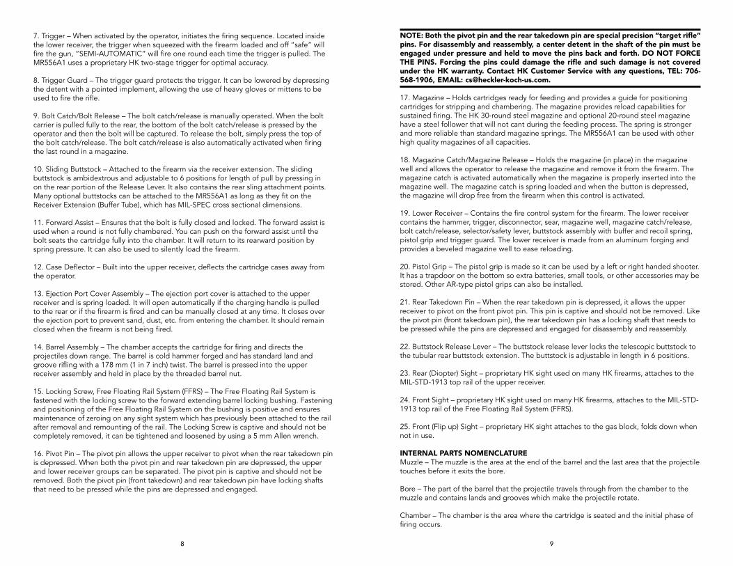
NOTE: Both the pivot pin and the rear takedown pin are special precision “target rifle” pins. For disassembly and reassembly, a center detent in the shaft of the pin must be engaged under pressure and held to move the pins back and forth. DO NOT FORCE THE PINS. Forcing the pins could damage the rifle and such damage is not covered under the HK warranty. Contact HK Customer Service with any questions, TEL: 706-568-1906, EMAIL: [email protected].
17. Magazine – Holds cartridges ready for feeding and provides a guide for positioning cartridges for stripping and chambering. The magazine provides reload capabilities for sustained firing. The HK 30-round steel magazine and optional 20-round steel magazine have a steel follower that will not cant during the feeding process. The spring is stronger and more reliable than standard magazine springs. The MR556A1 can be used with other high quality magazines of all capacities.
18. Magazine Catch/Magazine Release – Holds the magazine (in place) in the magazine well and allows the operator to release the magazine and remove it from the firearm. The magazine catch is activated automatically when the magazine is properly inserted into the magazine well. The magazine catch is spring loaded and when the button is depressed, the magazine will drop free from the firearm when this control is activated.
19. Lower Receiver – Contains the fire control system for the firearm. The lower receiver contains the hammer, trigger, disconnector, sear, magazine well, magazine catch/release, bolt catch/release, selector/safety lever, buttstock assembly with buffer and recoil spring, pistol grip and trigger guard. The lower receiver is made from an aluminum forging and provides a beveled magazine well to ease reloading.
20. Pistol Grip – The pistol grip is made so it can be used by a left or right handed shooter. It has a trapdoor on the bottom so extra batteries, small tools, or other accessories may be stored. Other AR-type pistol grips can also be installed.
21. Rear Takedown Pin – When the rear takedown pin is depressed, it allows the upper receiver to pivot on the front pivot pin. This pin is captive and should not be removed. Like the pivot pin (front takedown pin), the rear takedown pin has a locking shaft that needs to be pressed while the pins are depressed and engaged for disassembly and reassembly.
22. Buttstock Release Lever – The buttstock release lever locks the telescopic buttstock to the tubular rear buttstock extension. The buttstock is adjustable in length in 6 positions.
23. Rear (Diopter) Sight – proprietary HK sight used on many HK firearms, attaches to the MIL-STD-1913 top rail of the upper receiver.
24. Front Sight – proprietary HK sight used on many HK firearms, attaches to the MIL-STD-1913 top rail of the Free Floating Rail System (FFRS).
25. Front (Flip up) Sight – proprietary HK sight attaches to the gas block, folds down when not in use.
INTERNAL PARTS NOMENCLATUREMuzzle – The muzzle is the area at the end of the barrel and the last area that the projectile touches before it exits the bore.
Bore – The part of the barrel that the projectile travels through from the chamber to the muzzle and contains lands and grooves which make the projectile rotate.
Chamber – The chamber is the area where the cartridge is seated and the initial phase of firing occurs.
7. Trigger – When activated by the operator, initiates the firing sequence. Located inside the lower receiver, the trigger when squeezed with the firearm loaded and off “safe” will fire the gun, “SEMI-AUTOMATIC” will fire one round each time the trigger is pulled. The MR556A1 uses a proprietary HK two-stage trigger for optimal accuracy.
8. Trigger Guard – The trigger guard protects the trigger. It can be lowered by depressing the detent with a pointed implement, allowing the use of heavy gloves or mittens to be used to fire the rifle.
9. Bolt Catch/Bolt Release – The bolt catch/release is manually operated. When the bolt carrier is pulled fully to the rear, the bottom of the bolt catch/release is pressed by the operator and then the bolt will be captured. To release the bolt, simply press the top of the bolt catch/release. The bolt catch/release is also automatically activated when firing the last round in a magazine.
10. Sliding Buttstock – Attached to the firearm via the receiver extension. The sliding buttstock is ambidextrous and adjustable to 6 positions for length of pull by pressing in on the rear portion of the Release Lever. It also contains the rear sling attachment points. Many optional buttstocks can be attached to the MR556A1 as long as they fit on the Receiver Extension (Buffer Tube), which has MIL-SPEC cross sectional dimensions.
11. Forward Assist – Ensures that the bolt is fully closed and locked. The forward assist is used when a round is not fully chambered. You can push on the forward assist until the bolt seats the cartridge fully into the chamber. It will return to its rearward position by spring pressure. It can also be used to silently load the firearm.
12. Case Deflector – Built into the upper receiver, deflects the cartridge cases away from the operator.
13. Ejection Port Cover Assembly – The ejection port cover is attached to the upper receiver and is spring loaded. It will open automatically if the charging handle is pulled to the rear or if the firearm is fired and can be manually closed at any time. It closes over the ejection port to prevent sand, dust, etc. from entering the chamber. It should remain closed when the firearm is not being fired.
14. Barrel Assembly – The chamber accepts the cartridge for firing and directs the projectiles down range. The barrel is cold hammer forged and has standard land and groove rifling with a 178 mm (1 in 7 inch) twist. The barrel is pressed into the upper receiver assembly and held in place by the threaded barrel nut.
15. Locking Screw, Free Floating Rail System (FFRS) – The Free Floating Rail System is fastened with the locking screw to the forward extending barrel locking bushing. Fastening and positioning of the Free Floating Rail System on the bushing is positive and ensures maintenance of zeroing on any sight system which has previously been attached to the rail after removal and remounting of the rail. The Locking Screw is captive and should not be completely removed, it can be tightened and loosened by using a 5 mm Allen wrench.
16. Pivot Pin – The pivot pin allows the upper receiver to pivot when the rear takedown pin is depressed. When both the pivot pin and rear takedown pin are depressed, the upper and lower receiver groups can be separated. The pivot pin is captive and should not be removed. Both the pivot pin (front takedown) and rear takedown pin have locking shafts that need to be pressed while the pins are depressed and engaged.
10 11
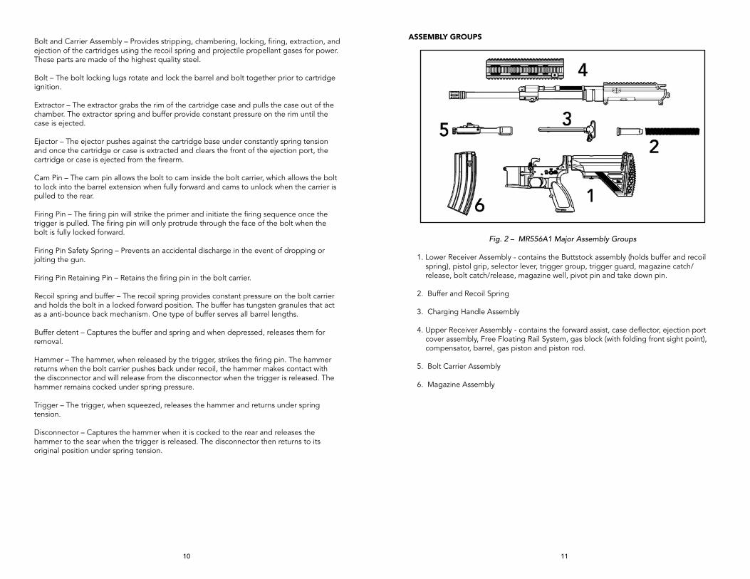
ASSEMBLY GROUPS
Fig. 2 – MR556A1 Major Assembly Groups
1. Lower Receiver Assembly - contains the Buttstock assembly (holds buffer and recoil spring), pistol grip, selector lever, trigger group, trigger guard, magazine catch/release, bolt catch/release, magazine well, pivot pin and take down pin.
2. Buffer and Recoil Spring
3. Charging Handle Assembly
4. Upper Receiver Assembly - contains the forward assist, case deflector, ejection port cover assembly, Free Floating Rail System, gas block (with folding front sight point), compensator, barrel, gas piston and piston rod.
5. Bolt Carrier Assembly
6. Magazine Assembly
Bolt and Carrier Assembly – Provides stripping, chambering, locking, firing, extraction, and ejection of the cartridges using the recoil spring and projectile propellant gases for power. These parts are made of the highest quality steel. Bolt – The bolt locking lugs rotate and lock the barrel and bolt together prior to cartridge ignition.
Extractor – The extractor grabs the rim of the cartridge case and pulls the case out of the chamber. The extractor spring and buffer provide constant pressure on the rim until the case is ejected.
Ejector – The ejector pushes against the cartridge base under constantly spring tension and once the cartridge or case is extracted and clears the front of the ejection port, the cartridge or case is ejected from the firearm.
Cam Pin – The cam pin allows the bolt to cam inside the bolt carrier, which allows the bolt to lock into the barrel extension when fully forward and cams to unlock when the carrier is pulled to the rear.
Firing Pin – The firing pin will strike the primer and initiate the firing sequence once the trigger is pulled. The firing pin will only protrude through the face of the bolt when the bolt is fully locked forward.
Firing Pin Safety Spring – Prevents an accidental discharge in the event of dropping or jolting the gun.
Firing Pin Retaining Pin – Retains the firing pin in the bolt carrier.
Recoil spring and buffer – The recoil spring provides constant pressure on the bolt carrier and holds the bolt in a locked forward position. The buffer has tungsten granules that act as a anti-bounce back mechanism. One type of buffer serves all barrel lengths.
Buffer detent – Captures the buffer and spring and when depressed, releases them for removal.
Hammer – The hammer, when released by the trigger, strikes the firing pin. The hammer returns when the bolt carrier pushes back under recoil, the hammer makes contact with the disconnector and will release from the disconnector when the trigger is released. The hammer remains cocked under spring pressure.
Trigger – The trigger, when squeezed, releases the hammer and returns under spring tension.
Disconnector – Captures the hammer when it is cocked to the rear and releases the hammer to the sear when the trigger is released. The disconnector then returns to its original position under spring tension.

12 13
SECTION 3 — FUNCTION AND OPERATION The function and operation of the MR556A1 is similar to that found in semi-automatic firearms and consists of eights steps: (1) Feeding, (2) Chambering, (3) Locking, (4) Firing, (5) Unlocking, (6) Extracting, (7) Ejecting, and (8) Cocking.
These eight steps are explained below with a brief description of what occurs inside the rifle during each step. Assume that a full magazine is loaded in the rifle with the magazine follower spring forcing the follower and thus the top cartridge into the path of the bolt and the bolt is locked to the rear.
(1) Feeding. The bolt is released from the bolt catch, either by deploying and then releasing the charging handle or by depressing the bolt catch. The bolt assembly moves forward, being driven by the expansion of the recoil spring. The bottom locking lugs on the bolt head act as a feed pawl, striking the top cartridge off the magazine and moving the cartridge towards the chamber in rear of the barrel.
(2) Chambering. The recoil spring continues to drive the bolt assembly forward until the bolt head seats the cartridge into the barrel’s chamber. Chambering is complete when the extractor snaps into the extracting groove on the cartridge and the ejector is forced into the face of the bolt.
(3) Locking. Locking occurs when the bolt reaches its limit of forward travel. When the bolt is moving forward, the cam pin orients the bolt head by ensuring that the locking lugs on the bolt head will pass between the gaps of the locking lugs located on the barrel extension (chamber). The bolt then strikes the back of the barrel and then stops. The action spring continues to move the bolt head carrier forward, thus causing the cam pin to pivot on the bolt head’s raceway. This action pivots the bolt head and rotates the bolt head’s locking lugs counter-clockwise until they engage the locking lugs on the barrel extension. The bolt assembly is now locked into the upper receiver.
(4) Firing. Firing occurs when the firing pin strikes the primer in the head of the cartridge. When the trigger is pulled, the trigger’s sear surface disengages from the hammer’s intercept notch and the hammer releases. The hammer moves forward under pressure from the hammer spring, disengaging the drop safety, striking the firing pin, and overcoming the inertia of the firing pin spring. This drives the firing pin against the primer, which in turn ignites the propellant in the cartridge case and propels the bullet through the barrel.
(5) Unlocking. Unlocking occurs after a cartridge is fired. As the bullet is forced through the barrel by expanding gases, a small amount of gas enters through the gas port into the gas block. The gas block features a small expansion chamber that quickly fills up with gas. The gas then hits the front of the gas piston, causing the three piston rings to expand, and driving the gas piston rearwards. Because the pusher rod is mounted in the gas piston, the pusher rod moves back as well. The back of the pusher rod hits the anvil (string surface) on top of the bolt head carrier, causing the bolt head carrier to move rearwards. As the bolt carrier assembly moves rearward, the bolt cam pin rotates and unlocks the bolt from the locking lug recesses in the barrel extension. The unlocked bolt is now ready to move rearward. Any remaining gas follows the bullet out of the muzzle.
(6) Extracting. Extracting removes the empty cartridge case from the chamber. As the bolt unlocks, the bolt rotates slightly counterclockwise, causing the extractor to rotate the cartridge case within the chamber. The expanded case breaks contact with the chamber walls, allowing extraction to occur.
(7) Ejecting. Ejecting throws the empty cartridge case out of the receiver. As soon as the bolt has drawn the cartridge case clear of the chamber, the force of the ejector spring and plunger pushes the cartridge case head away from the bolt face. This causes the forward end of the cartridge case to move outward to the right. A deflector on the outside of the upper receiver deflects the cartridge case away from operator.
(8) Cocking. Cocking occurs when the hammer is forced into position for firing the next cartridge. This happens as the bolt carrier assembly travels toward the rear. The bolt carrier assembly forces the hammer back and rides over it. The hammer is caught by the disconnector if the trigger is still held to the rear and by the trigger’s sear surface if the trigger has been released.
SELECTOR/SAFETY LEvER FUNCTION
NOTE: The MR556A1 has ambidextrous selector/safety levers, that is safety levers located on both sides of the lower receiver. Either lever can be manipulated and moves the lever on the other side. Unlike many AR-style firearms, the selector/safety levers of the MR556A1 can be placed on the “SAFE” position even if the MR556A1 is not cocked.
“SAFE POSITION” – Place the selector lever with the point facing towards the closed white box containing a bullet symbol with an “X” over it (towards the muzzle, Fig. 3).
“SEMI-AUTOMATIC POSITION”– Place the selector lever with the point towards the closed red box containing a red bullet symbol in it (straight up position) (Fig. 4).
Fig. 3 – SAFE Fig. 4 – SEMI-AUTO

14 15
SECTION 4 — SIGHTS, SIGHT ADjUSTMENT, AND AIMING
MR556A1 rifles can accommodate a wide variety of optical and mechanical (iron) sights.
HK DIOPTER SIGHTSFor models with HK Diopter rotary sight sets, the sights are installed on the MIL-STD- 1913 (Picatinny) rail with a Phillips #2 screwdriver or the HK sight tool (Fig. 5 & 6). Do not over tighten the screws.
Fig. 5 – Front Diopter Sight Fig. 6 – Rear Diopter Sight
For optimal sight use and the longest sight radius, the front sight is installed on the most forward portion of the MIL-STD-1913 rail and the rear sight is installed on the most rearward portion of the MIL-STD-1913 rail (located on the upper receiver). Sight adjustment is as follows:
The sight adjustment is a rear sight adjustment, so the movement of the sight will be in the same direction the shooter wants the impact of the round to move. If the hit is to the right of the intended location, then the sights and the impact must be moved left. Any corrections which may be required when sighting-in the weapon may only be performed by adjusting the rear sight for elevation or windage. MR rifles are designed to be sighted in at a range of 100 meters. REMEMBER THIS FORMULA: LL=C (Lower or Left = Clockwise rotation)
ELEvATION ADjUSTMENTInsert elevation adjustment tool into the rear sight cylinder so that the wedges of the tool engage in the two slots in the cylinder which contain the catch bolts. Press Phillips-head screwdriver downward into the adjustment tool and hold firmly. Rotate rear sight cylinder manually in the desired direction (Fig. 7).
After correction withdraw Phillips-head screwdriver and remove elevation adjustment tool. The catch bolts will then re-engage in the slots. After performing the elevationadjustment set the desired aperture again.
NOTE: One-quarter turn of the rear sight drum will move the impact of the round approximately 3.8 centimeters (1.5 inches) at 100 meters
Fig. 7 – Rear Fig. 8 – Clamping Screw Fig. 9 – Windage Sight Adjustment (to tighten turn clockwise) Adjustment
ELEvATION ADjUSTMENT (Alternative method without sight tool)Use of the HK Sight Adjustment Tool (HK ID # 300009) is always recommended to adjust the windage and elevation on any HK firearms equipped with standard diopter sights. However, some needle nose pliers can be substituted in the event that a sight adjustment tool is not available to perform range adjustments.
Ensure that the MR556A1 is unloaded before performing any adjustment to the sights. Use needle noose pliers with smooth jaws rather the serrated jaws as the serrated surfaces may cause chips and burrs on the spring loaded catch bolts. Simply insert the jaws onto the small shelf on the catch bolts and carefully squeeze while simultaneously rotating the drum. This action withdraws the catch bolts and allows the drum to be rotated either clockwise or counter-clockwise. To lower the point of impact, rotate the drum clockwise and to raise the point of impact, rotate the drum counter-clockwise. Ensure that the catch bolts engage the vertical slots located on the inside of the drum after removing the needle nose pliers.
WINDAGE ADjUSTMENTPoint of impact, left: Loosen clamping screw on top of sight base (Fig. 8). Turn adjustingscrew on the right side counterclockwise (Fig. 9) in accordance with the required correction. Then retighten clamping screw. This will move the impact to the Right.Point of impact, right: Loosen clamping screw (Fig. 8). Turn adjusting screw clockwise (Fig. 9) until the required correction has been performed. Then retighten clamping screw. This will move the impact to the Left.
NOTE: Each revolution of the Windage screw will move the impact of the round 15.2 cm (6 inches) at 100 meters.
TROY ACCESSORY SIGHTSSome MR556A1 rifles are supplied with Troy Industries Micro Folding Sights. Aiming and sight picture are similar to using the HK diopter sights.
Fig. 10 – Installing front TROY sight Fig. 11 – Tightening front TROY sight
INSTALLING TROY ACCESSORY SIGHTS (FRONT)1. Unscrew clamping assembly and place the sights at the desired location on the
Picatinny rail (Fig. 10).2. Apply one drop of tread locking compound to the exposed threads of the clamping
screw. Replace the clamping plate and tighten the clamping screw while pushing sight forward against the cross-slot (Fig. 11). To raise the sight, grasp and pull up until the sights locks in the upright position. To fold the sight, depress the button on the left side of the base and fold down. (Fig. 12)

16 17
Fig. 12 – Folding (lowering) Fig. 13 – Lowered sight TROY front sight TROY front sights INSTALLING TROY REAR SIGHTS
1. The rear TROY sight installs similar to the front sights. Unscrew clamping assembly and place the sights at the desired location on the Picatinny rail.
2. To raise the sight, grasp and pull up until the sights locks in the upright position. To fold (lower) the sight, depress the button on the left side of the base and fold down. (Fig. 14-16)
Fig. 14 – Rear Sight Fig. 15 – Lowering Fig. 16 – Rear sight Rear Sight folded (lowered)
FRONT SIGHT ADjUSTMENT ZEROING1. Fire a group of four (4) shots and measure the average distance for point-of -aim to
point-of-impact.2. Adjust front sight for elevation only.3.Windage adjustments are made with the rear sight.4. Confirm zero with a group of four aimed shots and adjust is necessary
Fig. 17 – Front sight adjustment Fig. 18 – Using a bullet tip to adjust the front sightFRONT SIGHT ADjUSTMENTTo move the bullet impact up, turn the adjustment wheel to the right/clockwise (Fig. 17 & 18). To move the bullet impact down, turn the adjustment wheel to the left/counter clockwise (Fig. 18 & 19).
Fig. 19 – Rear Sight Fig. 20 – Windage adjustment
REAR SIGHT ADjUSTMENTWindage adjustment can be made by inserting a pointed object (like a bullet tip) or a flat object (like a screwdriver or coin) into the coin slot and turning the adjustment wheel. To move the bullet impact right, turn the adjustment wheel to the right/clockwise. To move the bullet impact left, turn the adjustment wheel to the left /counter clockwise (Fig. 19 & 20).
Fig. 21 – Rear Sight Fig. 22 – Changing aperture
The Troy rear sight also offers a choice of two flip-style apertures, both large and small (Fig. 22). The large aperture is for close engagement and the small aperture is for more distant shooting. Generally the large aperture works best for alignment with the front sight and for short and medium ranges. Elevation does not change when switching apertures. For long range shots, the small aperture can be flipped into position by finger pressure on the top of the rear sight.
value for 1 click of adjustment Troy Micro Sights 100 meters 200 meters 300 metersM4/HK416/MR556A1 sight radius .50 MOA 5/8” 1-1/8” 1-5/8”
INSTALLING THE OPTIONAL HK FLIP-UP FRONT SIGHT Press front sight onto front sight holder until the axes holes of front sight and front sight holder are aligned. Push through front sight axles all the way, from the right to the left and secure the front sight axles by snapping the retaining clip. Check function of foldable front sight (Fig. 23 & 24).
Fig. 23 Fig. 24
18 19
SECTION 5 — AMMUNITION
By using ammunition with match bullets or other match grade ammunition the MR556A1 will achieve the best level of accuracy. Use ammunition of the appropriate caliber and of recent manufacture. The MR556A1 is chambered for 5.56 x 45 mm ammunition and will functioned safely and reliably with most high quality 5.56 mm and Caliber .223 Remington ammunition.
NOTE: Use only high quality 5.56 x 45 mm NATO or caliber .223 Remington ammunition in the MR556A1 rifle. Damage caused by the use of improperly assembled or remanufactured ammunition may void the HK Warranty. Do not use ammunition assembled with corrosive components (primers, propellants, etc.).
The MR556A1 is designed to use ammunition made to NATO or SAAMI specifications.
DO NOT USE• Reloads or remanufactured ammunition. Beware of military surplus, foreign or outdated
ammunition.• Non-jacketed or exposed lead ammunition.• Corrosive ammunition (primer and/or propellant).• Empty cases as “dummy“ (inert) rounds, as damage may result. Use complete dummy
rounds available for training purposes.• Any ammunition that exceeds NATO or SAAMI (Sporting Arms and Ammunition
Manufacturers’ Institute) pressure limits.• Cartridges that are not 5.56 x 45 mm or Caliber .223.• Seriously corroded ammunition.• Dented Cartridges.• Cartridges with loose bullets.• Cartridges exposed to extreme heat above 135°F (57°C) until they have cooled.• Use only authorized ammunition that is manufactured to NATO and SAAMI specs.• Ammunition that is wet or dirty.
WARNING: Only use ammunition designed to NATO and SAAMI specifications that is factory-loaded, undamaged, and of the correct caliber. The use of low powered cartridges could lead to functional stoppages (including bullets stuck in the barrel) and is not recommended.
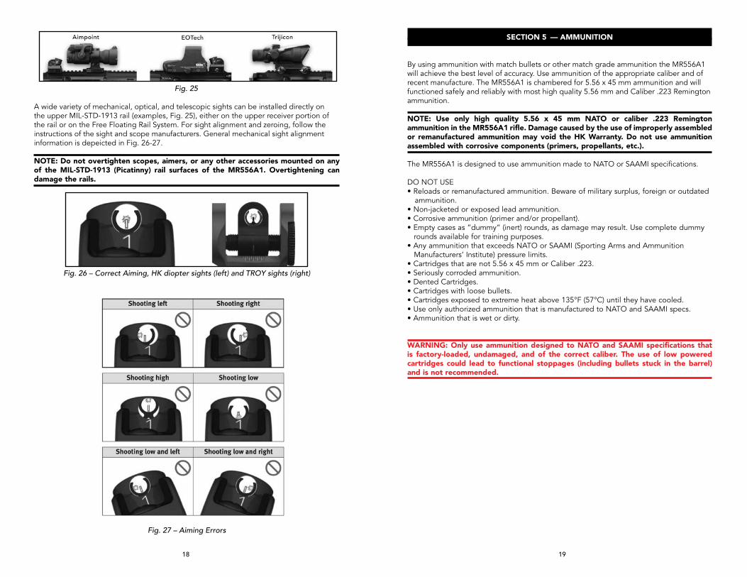
Fig. 25
A wide variety of mechanical, optical, and telescopic sights can be installed directly on the upper MIL-STD-1913 rail (examples, Fig. 25), either on the upper receiver portion of the rail or on the Free Floating Rail System. For sight alignment and zeroing, follow the instructions of the sight and scope manufacturers. General mechanical sight alignment information is depeicted in Fig. 26-27.
NOTE: Do not overtighten scopes, aimers, or any other accessories mounted on any of the MIL-STD-1913 (Picatinny) rail surfaces of the MR556A1. Overtightening can damage the rails.
Fig. 26 – Correct Aiming, HK diopter sights (left) and TROY sights (right)
Fig. 27 – Aiming Errors
20 21
SECTION 6 — INSTRUCTIONS FOR USE
LOADING A MAGAZINE
Magazines may be loaded by hand, one round at a time, or quickly loaded using a magazine filler and stripper clips. The use of a magazine filler and stripper clips is depicted below (Fig. 15).
Filling the magazine1. Hold the magazine with one hand. Place the cartridges onto the follower between the
magazine lips and push the cartridge, with your thumb, down underneath the lips and ensuring the projectile is facing the front of the magazine and that the cartridge rim is fully to the rear of the magazine.
2. Repeat this step until the magazine is filled with the appropriate number of cartridges (20 or less for a 20-round magazine and 30 or less for 30-round magazines). Do not overfill magazines.
Single roundsMagazines may be loaded with one round at a time by inserting the cartridge case in while depressing the follower and seating the case in until the projectile clears the front of the magazine. Continue this each time until the magazine is full. During and when finished filling the magazine gently tap the back of the magazine against the palm of your hand to ensure the rounds are seated properly.
CAUTION: Ensure cartridges, especially those to be loaded into the magazine, are free of sand, mud, moisture, frost, snow, ice, grease, or other foreign matter.
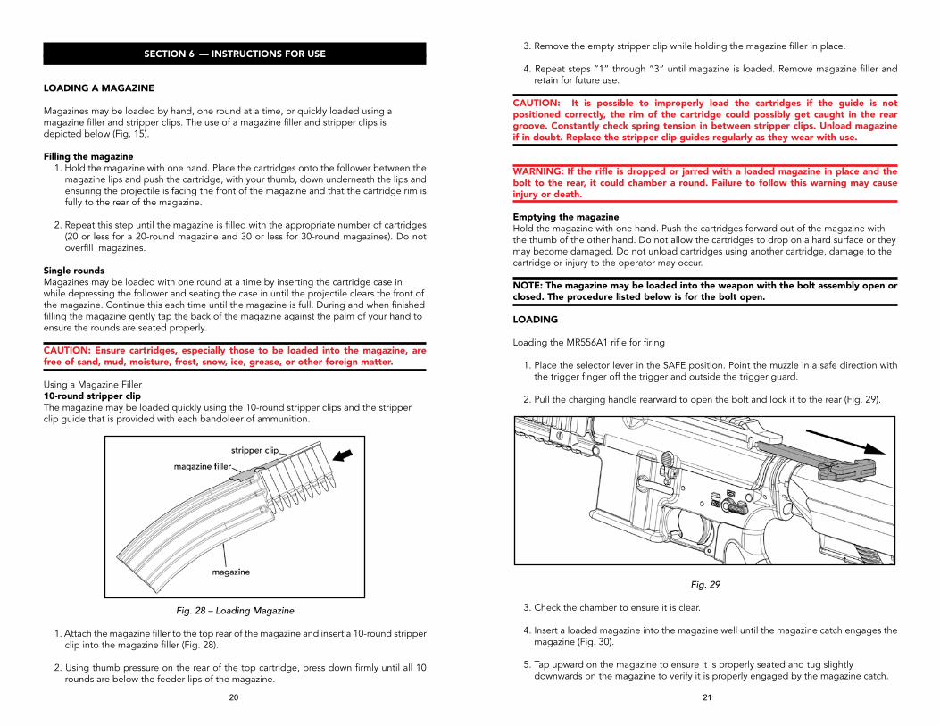
Using a Magazine Filler10-round stripper clipThe magazine may be loaded quickly using the 10-round stripper clips and the stripper clip guide that is provided with each bandoleer of ammunition.
Fig. 28 – Loading Magazine
1. Attach the magazine filler to the top rear of the magazine and insert a 10-round stripper clip into the magazine filler (Fig. 28).
2. Using thumb pressure on the rear of the top cartridge, press down firmly until all 10 rounds are below the feeder lips of the magazine.
3. Remove the empty stripper clip while holding the magazine filler in place.
4. Repeat steps “1” through “3” until magazine is loaded. Remove magazine filler and retain for future use.
CAUTION: It is possible to improperly load the cartridges if the guide is not positioned correctly, the rim of the cartridge could possibly get caught in the rear groove. Constantly check spring tension in between stripper clips. Unload magazine if in doubt. Replace the stripper clip guides regularly as they wear with use.
WARNING: If the rifle is dropped or jarred with a loaded magazine in place and the bolt to the rear, it could chamber a round. Failure to follow this warning may cause injury or death.
Emptying the magazineHold the magazine with one hand. Push the cartridges forward out of the magazine with the thumb of the other hand. Do not allow the cartridges to drop on a hard surface or they may become damaged. Do not unload cartridges using another cartridge, damage to the cartridge or injury to the operator may occur.
NOTE: The magazine may be loaded into the weapon with the bolt assembly open or closed. The procedure listed below is for the bolt open.
LOADING
Loading the MR556A1 rifle for firing
1. Place the selector lever in the SAFE position. Point the muzzle in a safe direction with the trigger finger off the trigger and outside the trigger guard.
2. Pull the charging handle rearward to open the bolt and lock it to the rear (Fig. 29).
Fig. 29
3. Check the chamber to ensure it is clear.
4. Insert a loaded magazine into the magazine well until the magazine catch engages the magazine (Fig. 30).
5. Tap upward on the magazine to ensure it is properly seated and tug slightly downwards on the magazine to verify it is properly engaged by the magazine catch.
22 23
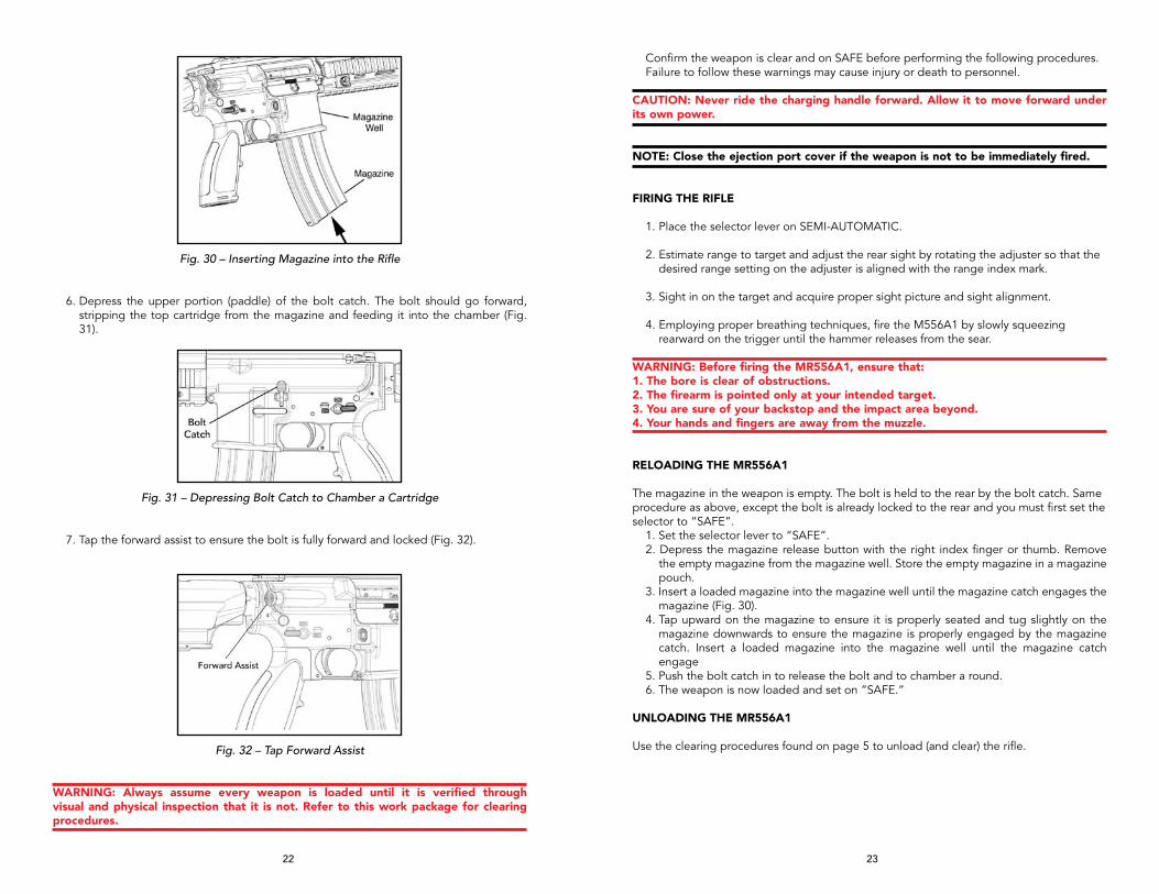
Fig. 30 – Inserting Magazine into the Rifle
6. Depress the upper portion (paddle) of the bolt catch. The bolt should go forward, stripping the top cartridge from the magazine and feeding it into the chamber (Fig. 31).
Fig. 31 – Depressing Bolt Catch to Chamber a Cartridge
7. Tap the forward assist to ensure the bolt is fully forward and locked (Fig. 32).
Fig. 32 – Tap Forward Assist
WARNING: Always assume every weapon is loaded until it is verified through visual and physical inspection that it is not. Refer to this work package for clearing procedures.
Confirm the weapon is clear and on SAFE before performing the following procedures.Failure to follow these warnings may cause injury or death to personnel.
CAUTION: Never ride the charging handle forward. Allow it to move forward under its own power.
NOTE: Close the ejection port cover if the weapon is not to be immediately fired.
FIRING THE RIFLE
1. Place the selector lever on SEMI-AUTOMATIC.
2. Estimate range to target and adjust the rear sight by rotating the adjuster so that the desired range setting on the adjuster is aligned with the range index mark.
3. Sight in on the target and acquire proper sight picture and sight alignment.
4. Employing proper breathing techniques, fire the M556A1 by slowly squeezing rearward on the trigger until the hammer releases from the sear.
WARNING: Before firing the MR556A1, ensure that: 1. The bore is clear of obstructions. 2. The firearm is pointed only at your intended target. 3. You are sure of your backstop and the impact area beyond. 4. Your hands and fingers are away from the muzzle.
RELOADING THE MR556A1
The magazine in the weapon is empty. The bolt is held to the rear by the bolt catch. Same procedure as above, except the bolt is already locked to the rear and you must first set the selector to “SAFE”.
1. Set the selector lever to “SAFE”.2. Depress the magazine release button with the right index finger or thumb. Remove
the empty magazine from the magazine well. Store the empty magazine in a magazine pouch.
3. Insert a loaded magazine into the magazine well until the magazine catch engages the magazine (Fig. 30).
4. Tap upward on the magazine to ensure it is properly seated and tug slightly on the magazine downwards to ensure the magazine is properly engaged by the magazine catch. Insert a loaded magazine into the magazine well until the magazine catch engage
5. Push the bolt catch in to release the bolt and to chamber a round.6. The weapon is now loaded and set on “SAFE.”
UNLOADING THE MR556A1
Use the clearing procedures found on page 5 to unload (and clear) the rifle.

24 25
SECTION 7 — DISASSEMBLY & ASSEMBLY
DISASSEMBLY (FIELD STRIPPING) OF THE MR556A1
Tools Needed: MR556A1 Disassembly Tool (located in the Buttstock), 5mm Allen Wrench
1. Clear the MR556A1a. Point the muzzle in a safe direction with the finger off the trigger and outside the
trigger guard.b. Place the selector lever on “SAFE”
NOTE: The MR556A1 has ambidextrous selector lever/safety levers, that is safety levers located on both sides of the lower receiver. Either lever can be manipulated and moves the lever on the other side. Unlike many AR-style firearms, the selector lever/safety levers of the MR556A1 can be placed on the “SAFE” position even if the MR556A1 is not cocked.
c. Remove the magazine (if applicable) by depressing the magazine release button located on the right hand side of the lower receiver.
d. Depress the catch located on the charging handle and rack the bolt to the rear two or three times in quick succession to extract and eject any cartridges that may have been loaded into the barrel.
e. Lock the bolt to the rear by pulling the charging handle all the way back. Once the bolt reaches its limit of rearward travel, depress the bottom of the bolt catch located on the left hand side of the lower receiver.
f. Perform a visual inspection of the chamber area to ensure that no live rounds are present in the MR556A1 prior to disassembly.
g. Return the bolt to battery (all the way forward) by either depressing the grooved paddle (top portion) of the bolt catch or by slightly pulling back on the charging handle until the bolt catch disengages from the bolt and then allow the action spring to move the bolt forward.
CAUTION: Never attempt to disassemble the MR556A1 with the bolt locked back to rear. After performing the clearance procedure, always ensure the bolt is forward before attempting to disassemble.
2. Separating the Upper and Lower Receivers:a. Rotate the recoil pad counter clockwise one quarter turn and separate the recoil pad
from the buttstock. Remove the MR556A1 disassembly tool (Fig. 33-34).
Fig. 33 – Removing the disassembly tool Fig. 34 – Disassembly tool
b. Insert the small tip of the disassembly tool into the spring loaded detent located in the center of the rear takedown pin. Push the disassembly tool from left to right until the takedown pin reaches its limit of lateral travel (Fig. 35, 36).
Fig. 35 – Takedown Pins Fig. 36 – Takedown Pin Detail
WARNING: Always use the disassembly tool to disengage the detents on both the rear takedown pin and the front pivot pin. Attempting to remove the pins without disengaging the detents could lead to damaging the lower receiver. Both the rear takedown pin and the front pivot pin are captive pins and will therefore remain attached to the lower receiver. Attempting to completely remove the takedown and pivot pins could lead to damaging the lower receiver.
3. Bolt Assembly:
a. Pivot the upper receiver from the lower receiver, depress the catch on the charging handle and withdraw the bolt assembly from the rear. Continue to pull the charging handle to the rear until resistance is encountered. Lift up on the charging handle and separate the charging handle from the upper receiver (Fig. 37).
Fig. 37 – Removing the Charging Handle
b. Insert the small tip of the disassembly tool into the spring loaded detent located in the center of the front pivot pin. Push the disassembly tool from left to right until the pivot pin reaches its limit of lateral travel. Separate the upper and lower receivers.
c. Insert the small tip of the disassembly tool into the right hand side of the firing pin retaining pin and drift the firing pin retaining pin from right to left until the firing pin retaining pin reaches its limit of lateral travel (Fig. 38)
WARNING: The firing pin retaining pin is a captive pin and will therefore remain attached to the bolt carrier. Attempting to completely remove the firing pin retaining pin could lead to damage of the bolt assembly.
Fig. 38 – Remove the Firing Pin and Firing Pin Spring

26 27
d. Lift up on the spring loaded drop safety and remove the firing pin and firing pin spring (Fig. 39).
Fig. 39 – Drift out the Firing Pin Retaining Pin
e. Lift up and remove the cam pin from the shaft of the bolt head (Fig. 40).
Fig. 40 – Remove the Cam Pin
f. Slide the bolt head from the front of the bolt carrier (Fig. 41).
Fig. 41 – Slide the Bolt Head out
g. Depress the rear of the extractor to equalize pressure and then drift out extractor pin utilizing the small tip of the disassembly tool. The rifle’s firing pin can also be used The extractor pin can be removed from either direction (Fig. 42).
Fig. 42– Drift out the Extractor Pin
h. Separate the extractor from the bolt head (Fig. 43).
Fig. 43 – Separate the extractor form the bolt head
CAUTION: Only remove the extractor spring and buffer from the extractor if worn, or damaged. Note that both the extractor spring and buffer features a slight taper to help mount these items onto the extractor. Constant removal and installation of the spring and buffer could lead to decreased service life of these parts and could impair the function of the MR556A1.
4. Upper Receivera. Insert a 5mm hex (Allen) wrench into the retaining screw located on the lower right
hand side of the Free Floating Rail System (handguard) and rotate counter clockwise (Fig. 44). Once loosened, drift out the retaining screw from left to right until the retaining screw reaches its limit of lateral travel.
WARNING: The retaining screw for the Free Floating Rail System (FFRS) handguard is held captive by a small shaped spring located on the lower right hand side of the handguard. Attempting to completely remove the retaining screw could lead to damage of the handguard, shaped spring, and/or retaining screw.
28 29
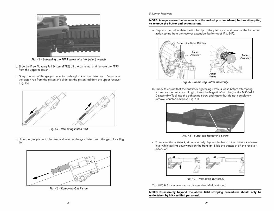
Fig. 44 – Loosening the FFRS screw with hex (Allen) wrench
b. Slide the Free Floating Rail System (FFRS) off the barrel nut and remove the FFRS from the upper receiver.
c. Grasp the rear of the gas piston while pushing back on the piston rod. Disengage the piston rod from the piston and slide out the piston rod from the upper receiver (Fig. 45).
Fig. 45 – Removing Piston Rod
d. Slide the gas piston to the rear and remove the gas piston from the gas block (Fig. 46).
Fig. 46 – Removing Gas Piston
5. Lower Receiver:
NOTE: Always ensure the hammer is in the cocked position (down) before attempting to remove the buffer and action spring.
a. Depress the buffer detent with the tip of the piston rod and remove the buffer and action spring from the receiver extension (buffer tube) (Fig. 347).
Fig. 47 – Removing Buffer Assembly
b. Check to ensure that the buttstock tightening screw is loose before attempting to remove the buttstock. If tight, insert the large tip (3mm hex) of the MR556A1 Disassembly Tool into the tightening screw and rotate (but do not completely remove) counter clockwise (Fig. 48).
Fig. 48 – Buttstock Tightening Screw
c. To remove the buttstock, simultaneously depress the back of the buttstock release lever while pulling downwards on the front lip. Slide the buttstock off the receiver extension.
Fig. 49 – Removing Buttstock
The MR556A1 is now operator disassembled (field stripped).
NOTE: Disassembly beyond the above field stripping procedures should only be undertaken by HK certified personnel.

30 31
REASSEMBLY (ASSEMBLY) OF THE MR556A1
Tools Needed: MR556A1 Disassembly Tool (located in the Buttstock), 5mm Allen Wrench, Small Straight Slot Screwdriver
1. Lower Receiver:a. Check to ensure that the buttstock tightening screw is loose before attempting to install
the buttstock. If tight, insert the large tip (3mm hex) of the MR556A1 Disassembly Tool into the tightening screw and rotate (but do not completely remove) counter clockwise.
b. Two small set screws are located on the bottom of the receiver extension (buffer tube). These set screws are provided to eliminate any play that may develop between the buttstock and the extension. The left hand side of the set screw features a detent surface that engages the buttstock. The right hand surface features a cut to accommodate a small straight slot screwdriver. Rotating the set screws clockwise will tighten the detents to the buttstock; rotating the setscrew counter clockwise will loosen the buttstock. Using a straight slot screwdriver, rotate the set screws clockwise using quarter turns and adjust until the detents engage the buttstock but do not hinder removal or installation (Fig. 50)
Fig. 50 – Buttstock reassembly
c. Depress the back of the buttstock release lever allowing the front tab to pivot downwards. Pull down on the front tab until the locking pin is not visible inside the buttstock. Mount the buttstock onto the receiver extension. The buttstock is adjustable for length of pull, with six different settings available to the operator.
WARNING: Ensure that only the proprietary HK buffer (marked with the HK logo and red dot) and recoil spring (action spring), also marked with red paint, are installed in the MR556A1. Use of non HK buffers and recoil springs could result in cycling problems and affect the reliability of the MR556A1 (Fig. 51).
Fig. 51 – HK Proprietary Buffer
d. Ensure that the hammer is in the down (cocked) position before attempting to install the buffer and action spring. Mount the action spring onto the buffer and insert the buffer and spring into the receiver extension. Push back on the buffer far enough until the buffer is retained by the spring loaded buffer detent (Fig. 52).
Fig. 52 – Installing the buffer and action spring
2. Upper Receiver:
a. Install the gas piston into the back of the gas block. The piston rings need not be staggered prior to installation (Fig. 53).
Fig. 53 – Reinstalling the Gas Piston and the Piston Rod
b. Insert the rear of the piston rod into the bushing located at the front of the upper receiver above the barrel nut, compress the spring, and install the front tip of the piston rod into the rear of the gas piston.
c. Slide the Free Floating Rail System (FFRS-handguard) onto the barrel nut, ensuring that the tongue on the FFRS mounts into the groove on top of the upper receiver. Once the FFRS is flush with the upper receiver, drift in the captive FFRS retaining screw. Insert a 5mm hex wrench into the retaining screw and rotate clockwise until hand tight.
Fig. 54 – Reinstalling the FFRS handguard

32 33
3. Bolt Assembly:
a. Mount the extractor spring and buffer onto the extractor, ensuring that the wider surface of both the spring and buffer are mounted on the circular mounting surface on the extractor and that the tapered (narrower) surface faces upwards (Fig. 55).
Fig. 55 – Extractor reassembly
b. Insert the extractor with spring and buffer into the bolt head. Place pressure on the back of the extractor, line up the mounting surfaces and install the extractor pin. Ensure the extractor pin is centered in the bolt head before attempting to install the bolt head into the bolt carrier (Fig 43).
Fig. 56 – Bolt Head reassembly
NOTE: The bolt head on the MR556A1 features a tapered mounting surface for the cam pin. This feature ensures that the bolt must be properly positioned in the bolt carrier before attempting to install the cam pin.
c. Slide the bolt head into the bolt carrier until the circular mounting surface for the cam pin on the bolt heads aligns with the front of the raceway on the bolt head carrier. Pointed down range, the extractor should be on the right hand side of the bolt carrier and ejector should be on the left (Fig. 57).
Fig. 57 – Bolt Carrier reassembly
d. Insert the cam pin into the shaft of the bolt carrier, ensuring that the hole for the firing pin on the cam pin is aligned with the firing pin tunnels on both the bolt head and bolt carrier (Fig. 58).
Fig. 58 – Bolt Carrier reassembly
e. Ensure that the captive firing pin retaining pin is drifted completely out to the left hand side of the bolt carrier. Insert the firing pin spring onto the firing pin, pivot upwards on the spring loaded firing pin safety, and insert the firing pin and spring into the bolt carrier’s firing pin tunnel until the firing pin reaches its limit of forward travel (Fig. 59)
Fig. 59 – Installing the Firing Pin

34 35
f. While maintaining forward pressure on the back of the firing pin, drift the firing pin retaining pin from left to right.
g. Ensure that the firing pin retaining pin is properly installed by pivoting upwards on the firing pin safety while pushing backwards on the bolt head. The firing pin should be retained inside the bolt carrier (Fig. 60).
Fig. 60 – Firing Pin Retaining Pin Installation
h. Turn the upper receiver upside down, insert the charging handle into the upper receiver, align the lugs on the outsides of the charging handle with the recesses on the inside of the upper receiver then press down until the charging handle is flush with the inside of the receiver then press slightly forward (Fig. 61).
Fig. 62 – Charging Handle Installation
i.. With the upper receiver and charging handle upside down, install the bolt assembly onto the bottom of the charging handle ensuring that the bolt carrier’s anvil and the top of the cam pin are centered in the bottom cavity of the charging handle (Fig.63).
Fig. 63 – Installing the bolt assembly into the upper receiver
j. Push the charging handle and bolt group completely into the upper receiver until the locking lugs on the bolt head engage the locking on the barrel extension and the latch on the charging handle engages the oval locking surfaces on either the left or right hand sides of the upper receiver. The latch can be mounted on either the left or the right hand side of the charging handle (Fig. 64).
Fig. 64 – Completing installation of the bolt assembly into the upper receiver
4. Upper and Lower Receivers:
WARNING: Always use the Disassembly Tool to disengage the detents on both the rear takedown pin and the front pivot pin. Attempting to install the pins without disengaging the detents could lead to damage of the lower receiver.
a. Ensure that both the captive front pivot pin and rear takedown are drifted out to the right hand side of the receiver. If necessary, use the small surface of the MR556A1 disassembly tool.
b. Place the upper receiver pointed downwards with the flash hider resting on a padded surface.
c. Mount the lower receiver to the upper receiver. Drift the front pivot pin from right to left. The pivot pin will not completely lock but it will engage the upper receiver (Fig. 65).

36 37
d. Insert the small tip of the disassembly tool into the spring loaded detent located in the center of the rear takedown pin. While pushing on the disassembly tool, drift the takedown pin from right to left until the takedown pin reaches its limit of lateral travel. The tip of the takedown pin should be visible on the left hand side of the lower receiver (Fig. 66).
Fig. 65 – Closing Upper and Lower Receiver
e. Insert the small tip of the disassembly tool into the spring loaded detent located in the center of the front pivot pin. While pushing on the disassembly tool, drift the pivot pin from right to left until the pivot pin reaches its limit of lateral travel. The tip of the pivot pin should be visible on the left hand side of the lower receiver.
Fig. 66– Detail of the rear Takedown Pin showing spring loaded detent.
f. Install the disassembly tool into the storage channel located at the back of the buttstock.
g. Mount the recoil pad onto the back of the buttstock with the recoil pad perpendicular to the buttstock. Ensure that the recoil pad is flush with the buttstock and rotate the recoil pad clockwise one quarter turn until the recoil pad engages the locking surfaces located on both the top and bottom of the buttstock.
FUNCTION CHECK
WARNING: Always ensure the MR556A1 is unloaded prior to attempting to perform a function check.
NOTE: The MR556A1’s selector lever can be placed on safe regardless of the position of the hammer. Legacy AR15/M16 platforms require that the hammer be cocked prior to attempting to place the firearm on “SAFE”.
FUNCTION CHECK PROCEDURE
1. Perform clearing procedure (see above) and ensure selector lever is set on “Safe”.
2. Place the muzzle in a safe direction and rack the bolt to the rear three or four times in quick succession by using the charging handle. The bolt should not bind when traveling back and forth in the receiver.
3. “SAFE”: Let the bolt go forward and completely go into battery. With an unloaded MR556A1 and the muzzle in a safe direction, ensure the selector lever is set on “Safe” and attempt to pull the trigger. The hammer must not fall.
4. “SEMI-AUTOMATIC”: Rotate the selector lever to “Semi-Automatic” (Single Shot) and with an unloaded MR556A1 and the muzzle in a safe direction, attempt to pull the trigger and hold to the rear. The hammer must fall.
5. While maintaining pressure on the trigger, rack the bolt and release. The hammer should be held by the disconnector.
6. Release the trigger. The hammer should be caught by the sear as signified by a metallic click. Release the trigger completely and re-engage the trigger. Hammer must fall.
7. Insert an empty magazine into the magazine well and pull back on the charging handle. The magazine follower should engage the bolt catch and lock the bolt to the rear on an empty chamber.
8. Remove the magazine and allow the bolt to go into battery, either by depressing the bolt catch or by pulling the charging handle slightly back towards the rear and then releasing.
9. Ensure that the MR556A1 is unloaded, place the muzzle in a safe direction and pull the trigger to ease the tension on the trigger spring.
10. Place the selector lever back on “Safe” and snap the dust cover into position over the ejection port.

38 39
MAGAZINE DISASSEMBLY
CAUTION: Parts are under considerable spring pressure. Wear safety goggles and point the base of the magazine housing in a safe direction when disassembling or assembling. Read the complete procedure before attempting to disassemble the magazine.
To disassemble the magazine for cleaning or inspection, push in the locking plate (located behind the magazine floorplate) with a cleaning rod, cartridge, or similarly shaped object. As you depress the locking plate through the window of the floorplate, pull back towards the rubber bumper so the locking tab will exit the locking window of the housing. When the locking tab lifts up, the floor plate, locking plate, spring, and follower will come out under pressure from the housing (Fig. 67). The floorplate is easily removed from the locking plate, which is attached to the spring and follower. Take note as to the arrangement of these parts for assembly. For cleaning purposes, it is not necessary to disassemble the follower and locking plate from the spring (Fig. 68).
Fig. 67 – Magazine Disassembly (HK 30-Round Steel Magazine)
Fig. 68 – HK 30-Round Steel Magazine Components
ASSEMBLY (HK 30-ROUND STEEL MAGAZINE)To assemble the magazine, use the reverse sequence used for disassembly. If magazine was cleaned, ensure that it is properly lubricated prior to assembly. Attach the follower and locking plate to the spring and slide the follower into the magazine housing (it will only assemble in one direction, do not force it). Push the locking plate down into the housing enough so that you can place the floor plate tab into the recess, (using the side with the rubber bumper first). Let go of the locking plate and insert a cleaning rod or similarly shaped object into the window of the floorplate and depress the locking plate while applying pressure rearward against the rubber bumper so the locking tab will enter the recess (locking window) in the front of the magazine (Fig. 68).
Once the floorplate is assembled, make sure the locking plate is seated flush against the floor plate. Check the function of the magazine by tapping it on your hand. Also check the function of the follower, for free movement by depressing it with the cleaning rod. Lastly check the secure attachment to and fit of the magazine in the rifle.
CAUTION: It is possible to improperly load the cartridges if the guide is not positioned correctly, the rim of the cartridge could possibly get caught in the rear groove. Constantly check spring tension in between stripper clips. Unload magazine if in doubt. Replace the stripper clip guides regularly as they wear with use.
Using thumb pressure on the rear of the top cartridge, press down firmly until all ten rounds are below the feed lips of the magazine. Remove the empty stripper clip while holding the stripper clip guide in place. Repeat until the magazine is full. Remove stripper clip guide and retain it for future use.
Speed loaderHeckler & Koch does not warrant the use of alternate filling devices. Care should be taken when using non-approved devices in that damage may occur to the magazine that is not covered under warranty.
NOTE: Do not slam the magazine on a table or a fixed hard surface during filling or damage to the feed lips may occur. Instead apply gradual pressure to accomplish this task.
NOTE: Protect the magazines from drop-induced damage on hard surfaces (concrete, metal, etc.). Many weapon stoppages begin in feed devices that are not properly cared for or that are abused unnecessarily.

40 41
SECTION 8 — CLEANING & MAINTENANCE
CLEANING OF THE MR556A1There are no special requirements, cleaners, or lubricants required for cleaning the MR556A1. The standard HK cleaning kit that is used for all 5.56 mm HK rifles may be used for this firearm. Cleaning may be completed using dry cleaning solvent, bore cleaner, wiping with a cloth or an all-purpose nylon brush. Using these guidelines will determine which applies. Cleaning materials are pipe cleaners, swabs, all-purpose nylon brush and rags.
NOTE: If a solvent is used for cleaning, ensure all residual solvent is removed after cleaning, and then a coat of lubricant must be applied for protection against rust and the elements. Dry cleaning solvent may be used to completely remove lubricants. For example, when using the rifle in extreme cold weather, dry cleaning solvent may be used to remove traces of heavy lubricants before applying LAW. The following lubricants (or their commercial equivalents) can be used: TW25 B, Shooter Choice, LSA, LAW, or OX24.
Use solvents as follows:1. Place a few drops on a swab or rag.2. Clean the firearm with these swabs and rags until they come out clean.3. Thoroughly purge all surfaces when solvents were applied.4. Lubricate well in accordance with manufacturers’ recommendations.
CAUTION: Don’t “dry clean” your firearm. General Cleaning is required under normal conditions and the following procedures apply.
1. Always clean after firing, after the firearm is wet or in adverse weather conditions. Remove areas of powder fouling, debris and grit, corrosion and dirt. Clean the bore with a bore brush and a cable cleaning rod. Pull the brush from the chamber to the muzzle. Complete this several times with bore cleaner and let soak several minutes if time permits. Clean the chamber with the chamber brush and a solid cleaning rod handle. Rotate the chamber brush with bore cleaner by pushing and twisting and also let it soak for several minutes while the upper receiver, piston, piston rod and bolt carrier assembly are cleaned with the all purpose brush using bore cleaner. Wipe excess cleaner off with a rag and then run several patches through the bore with the cable rod from the chamber to the muzzle until there is no residue on the patch.
2. Use an all purpose nylon brush or swab and apply a light coat of lubrication with a clean swab to all the metal surfaces, including the bore, the locking lugs in the chamber and on the bolt. A drop of oil should be placed on the ejector, extractor, cam pin, trigger pin, hammer pin, charging handle spring and forward assist.
3. If the firearm has been disassembled, then all parts should be thoroughly cleaned and lubricated before assembly. This is the best time to inspect all the parts before assembly.
LUBRICATIONAll firearms require proper lubrication to function as designed and the MR556A1 is no exception. Absence of lubrication may impede the operation of the MR556A1, particularly in load-bearing or friction contact areas. Excessive lubrication may also cause function problems by acting as a magnet for dirt, grit, sand, and fouling. Many high quality, medium weight lubricants (oils) specifically designed for use on firearms, including those cited earlier will work well on the MR556A1. Do not use lubricants that boast of their ability to penetrate metal as these substances may deaden cartridge primers.
UPPER RECEIvERApply a light coat of a suitable lubricant to the interior of the upper receiver, bore and chamber, barrel nut, outer surfaces of barrel, barrel nut, front sight, surfaces under handguard and forward assist.
Fig. 69 – Lubrication of the Gas Piston, Piston Rod, and Barrel Nut Exterior
1. Apply a medium coat of lubricant on the gas piston and operating rod (Fig. 69)
Fig. 70 – Lubrication of the MR556A1 Bolt Carrier Assembly
2. Apply a light coat of lubricant to the extractor pin, the firing pin, firing pin spring, firing pin recess in the bolt. Apply a a medium coat of lubricant to the red areas (Fig 70).

42 43
3. Apply a medium coat of lubricant to the extractor (Fig. 70).
4. Apply a heavy coat of lubricant to the exterior of the bolt carrier, outside of the firing pin retaining pin, cam pin, and bolt head. Pay special attention to cam pin area inner and outer surfaces of bolt carrier, anvil, and bolt head’s locking lug.
Fig. 71 – Lubrication of MR556A1 Charging Handle
5. Apply a medium coat of lubricant to the interior and exterior surfaces of the charging handle (Fig. 71).
LOWER RECEIvER ASSEMBLY (FIG. 72 & 73)1. Apply a light coat of lubricant to the exterior of the receiver and receiver extension
(buffer tube), interior of the exterior metallic surfaces, exposed pins, and magazine springs.
2. Apply a medium coat of lubricant to takedown pins, pivot pins, detents, inside the buffer extension tube, buffer detent pin, springs inside the lower receiver, trigger mechanism, hammer, disconnector, and sear inside the lower receiver.
3. Apply a medium coat of lubricant on the (recoil) action spring, buffer.
Fig. 72 – Lubrication of MR556A1 Lower Receiver Assembly
Fig. 73 – MR556A1 Buttstock Assembly
Fig. 74 – MR556A1 Lubricant Guide
LUBRICATION SUMMARYNO Lubrication: (surface is dry and not slippery to the touch)• Plastic or rubber components• Sling webbing• Optics
LUBRICATION• Gas Piston and Gas Cylinder,• Buffer and recoil spring• Bolt, Bolt carrier, Cam pin and Firing Pin Safety• Extractor• Ejector• Barrel extension• Bore, chamber, locking surfaces of the chamber and bolt lugs• Receiver take down and pivot pin• Hammer, trigger, disconnector springs and selector lever in trigger group• Piston rod• All metal parts and/or any area where metal contacts metal.
44 45
Cleaning (HK 30-Round Steel Magazine)There are no special requirements, cleaners or lubricants for cleaning this magazine. The standard cleaning equipment that is used for the rifle may be used for this magazine. Refer to the care and cleaning section of this operator’s manual for more detailed information. Do not use metal bristle (brass or steel) or wire brushes to clean the magazine components as damage may occur to the protective qualities of the surface finish.
Cleaning may be completed using dry cleaning solvent, bore cleaner, wiping with a cloth or an all purpose nylon brush. Using these guidelines will determine which applies. Cleaning materials are pipe cleaners, swabs, all purpose nylon brush and rags.
NOTE: If cleaning is completed using a solvent, then a coat of lubricant must be applied for protection against rust and the elements. Dry cleaning solvent may be used to completely remove lubricants. For example, when moving to extreme cold weather operations, dry cleaning solvent may be used to remove traces of standard lubricants before applying a cold weather lubricant like “LAW.”
A variety of high quality lubricants, including some generic “cleaner, lubricant, and preservative” solutions, LSA (Lubricant, Small Arms) or LAW (Lubricant, Arctic Weather) — and their commercial equivalents and can be used on the HK magazine.
CAUTION: Don’t “dry clean” your magazines. Do not use hot water or other solvents or you could inadvertenly wash away Teflon lubricant that has been building up as a result of your using some cleaning, lubraticant, preservative solutions. Rifle Bore Cleaner (RBC) may be used on HK magazines to remove carbon.
General cleaning is required under normal conditions and the following procedures apply:
1. Always clean after firing, after magazine is wet or in adverse weather conditions. Remove areas of powder fouling, debris and grit, corrosion and dirt.
2. If magazine is assembled, clean carbon off of follower and feed lips with the all purpose nylon brush or swab and apply a light coat of lubrication with a clean swab. If the magazine has been disassembled, then all parts should be thoroughly cleaned and lubricated before assembly.
NOTE: Do not mix lubricants on the same magazine. The magazine must be thoroughly cleaned during the change from one lubricant to another. Dry cleaning solvent is recommended for cleaning during the change from one lubricant to another.
Lube guideUnder all but the coldest Arctic conditions, normal high quality lubricants can be used on your magazine. Between +10 degrees F (-12°C) and -10 degrees F (-23°C) either normal high quality lubricants or LAW may be used. Below -10 degrees F (-23°C) use LAW.
Inspection (HK 30-Round Steel Magazine)A visual inspection is recommended each and every time you clean the magazine, the magazine is disassembled, or a problem exists that could be magazine related. The following are guidelines that can help in identifying and solving magazine related problems.
Many problems are very often related to incorrect operator use or maintenance, faulty ammunition and/or problems in the weapon. These areas should be checked for problems at the same time the magazine is inspected. If the same problem exists with more than one magazine, then more than likely it is a rifle, operator or ammunition problem. When
problems do occur, mark/identify the suspect magazine with a tag or paint/grease pen and use the following as a guideline. Check for proper assembly. Inspect overall function of follower (free movement), locking tabs, dents, cracks, etc.
1. Housing: Inspect feed lips for dents and proper spacing, sides for dents, magazine catch area for worn surfaces or dents, cracks, etc.
2. Follower: Inspect for free movement inside of housing, dents, cracks and deformities.3. Spring: Inspect for bends, cracks, weak tension.4. Locking Plate: Inspect for worn or broken tabs. It should retain floor plate and stay
securely attached to the spring.5. Floor plate: Inspect for bends, cracks and correct fit of the locking tabs into the
locking recess of housing.6. Rubber bumper: Insure bumper retains floor plate into housing when assembled and
there are no signs of extreme wear.
If any problems are identified, repair or replace as necessary.
46 47
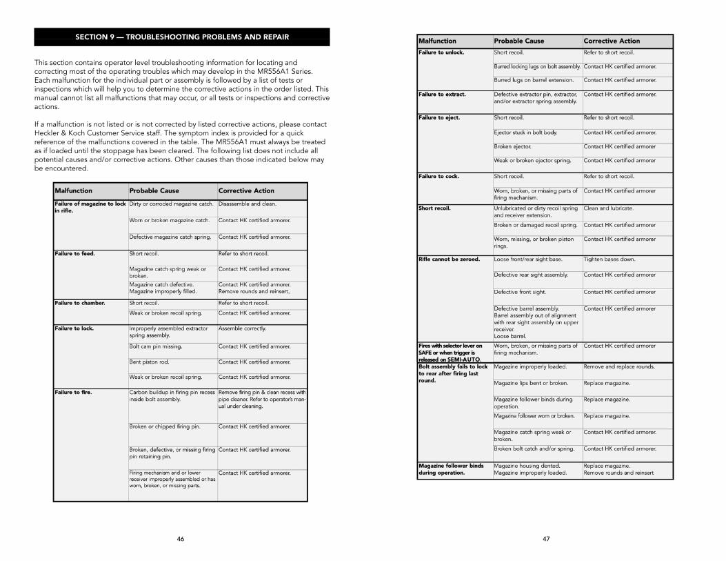
SECTION 9 — TROUBLESHOOTING PROBLEMS AND REPAIR
This section contains operator level troubleshooting information for locating and correcting most of the operating troubles which may develop in the MR556A1 Series. Each malfunction for the individual part or assembly is followed by a list of tests or inspections which will help you to determine the corrective actions in the order listed. This manual cannot list all malfunctions that may occur, or all tests or inspections and corrective actions.
If a malfunction is not listed or is not corrected by listed corrective actions, please contact Heckler & Koch Customer Service staff. The symptom index is provided for a quick reference of the malfunctions covered in the table. The MR556A1 must always be treated as if loaded until the stoppage has been cleared. The following list does not include all potential causes and/or corrective actions. Other causes than those indicated below may be encountered.

48 49
SECTION 10 — EXPLODED DIAGRAM AND PARTS LIST

50 51
1-97 MR556A1 Rifle 235973 1-19 Upper receiver, complete 235989 1-5 Barrel 16,5’’, complete 235990 1 Flash hider 233106 2 Gas block 235691 3 Clamping sleeve (2x) 979245 4 Barrel nut 203580 5 Barrel MR556 16.5’’, assembled 2358066 Gas piston, complete 205381 7 Rod, complete 203648 8 Upper receiver, assembled 235980 9 Axle for cover 203633 10 Ejection port cover, complete 203626 11 Clamping sleeve (roll pin) 979290 12 Elbow spring 203632 13 Clamping sleeve for forward assist 979313 14 Pressure spring for forward assist 203635 15-19 Forward assist, complete 203599 15 Pressure bolt for forward assist 203637 16 Pressure spring for pressure bolt 203636 17 Locking piece for forward assist 203601 18 Pressure bolt for locking piece 979293 19 Retainer, complete 203600 20-25 Charging handle, complete 235028 20 Clamping sleeve (roll pin) 928077 21 Clamping sleeve (roll pin) for pawl (2x) 236299 22 Charging handle 235232 23 Plate 227678 24 Pressure spring 203640 25 Pawl, complete 235377 26-28 Handguard, complete 236204 26 Handguard 23318527 Locking screw for handguard 236202 28 Shaped spring 233186 29-47 Bolt group, complete 236268 29-36 Bolt head, complete 235604 29 Ejector 233109 30 Pressure spring 233110 31 Cylindrical pin 203569 32 Bolt head 235605 33 Rubber plug 207779 34 Pressure spring 205407 35 Extractor 233108 36 Clamping sleeve (roll pin) 236320 37 Control bolt 233112 38-45 Bolt head carrier, complete 236266 38 Pressure spring 233132 39 Catch 233705 40 Rivet 233706 41 Clamping sleeve (roll pin) 984198 42 Compression spring 235022 43 Bolt 235238 44 Pin 235239 45 Bolt head carrier 236267 46 Pressure spring 233674 47 Firing pin 233703 48-97 Lower receiver, complete 236210 48 Buffer, complete 203570 49 Recoil spring (action spring) 233166 50-81 Lower receiver, assembled 236209 50 Stop pin for locking pin 233115 51 Pressure spring 233116 52 Locking pin (front takedown/pivot pin), complete 235941 53 Hammer, complete 235627 54 Axle (2x) 227886 55 Disconnector 227695 56 Pressure spring 233149 57 Sear release rocker 235731 58 Pressure spring 235000
59 Bridge 203593 60 Trigger 235732 61 Bolt catch/release 233129 62 Clamping sleeve (roll pin) for bolt catch/release 979292 63 Pressure spring for pressure pin 233132 64 Pressure pin 233131 65 Magazine catch 227611 66 Pressure spring 233126 67 Retainer for magazine catch 233127 68 Clamping sleeve (roll pin) for safety lever (2x) 984199 69 Safety lever (2x) 227870 70 Safety roller 236274 71 Pressure spring for locking pin (buffer detent) 233121 72 Locking pin for buffer (buffer detent) 233120 73 Clamping sleeve (roll pin) for locking pin 98654474 Trigger guard, complete 233153 75 Clamping sleeve for trigger guard 979294 76 Stop pin 233135 77 Pressure spring for stop pin 233136 78-79 Pistol grip, complete 234671 78 Pistol grip 234672 79 Cover, complete 234668 80 Cylindrical screw 979355 81 Lower receiver 235977 82 Locking pin (rear takedown pin), compl. 235931 83 Stop pin for locking pin 233115 84 Pressure spring 233116 85 Plate 233164 86 Nut for extension 233165 87 Buttstock extension buffer tube), compl. 236272 88-97 Buttstock concave, complete 236269 88 Buttstock 236271 89 Bolt 227378 90 Pressure spring 234688 91 Release lever 235920 92 Clamping sleeve (roll pin) 968761 93 Pressure spring 212846 94 Insert 235919 95 Threaded pin 967663 96 Hexagonal Allen key 235926 97 Buttstock cap, concave 22761698 HK steel 30 round magazine 251770S
Every attempt has been made to ensure the accuracy of this information, however errors or changes may occur.
Item Description Part Number Item Description Part Number
PARTS LIST (FOR EXPLODED DIAGRAM, PAGES 48-49)SECTION 11 — SPECIFICATIONS
Caliber 5.56 x 45 mm NATOOperating principle Gas operated, short stroke pistonBolt system Rotating boltFeed mechanism Magazines, 10/20/30 roundsMode of fire Semi-automatic DimensionsLength, maximum (stock extended) 37.68 in / 957 mmLength, minimum (stock retracted) 33.90 in / 861 mmWidth 3.07 in / 78 mmHeight 9.45 in / 240 mmBarrel length 16.5 in /421 mm Weight Rifle (with empty magazine, iron sights) 9.04 lb / 4.1 kgMagazine (empty 30 round magazine) .53 lb / .24 kg OtherTrigger pull 4.5 - 5.6 lbf / 20 - 25 N ( approximate) Barrel profile 6 lands & grooves, right twist, 1 in 7 in (178 mm)Sight radius* 14.60 in / 371 mmSights Diopter front and rear or accessory Troy Micro sightsAdjustable buttstock 6 positions, 96 mm of travel * varies as different sights and optics can be mounted on the HK Free Floating Rail System (Picatinny type, MIL-STD-1913), all specifications and technical data subject to modification
WARRANTY REGISTRATIONHeckler & Koch warranty registration for new firearms is now on-line. To register your new MR556A1 go to...http://hk-usa.com/warranty/register.html
If you don’t have access to the internet, call HK Customer Service at 706-568-1906 to obtain a warranty card.
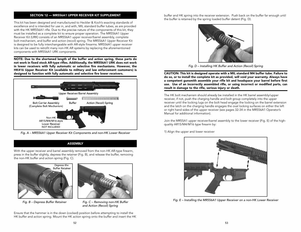
52 53
SECTION 12 — MR556A1 UPPER RECEIvER KIT SUPPLEMENT
This kit has been designed and manufactured to Heckler & Koch’s exacting standards of excellence and is intended for use in, and with, MIL standard buffer tubes, as are provided with the HK MR556A1 rifle. Due to the precise nature of the components of this kit, they must be installed as a complete kit to ensure proper operation. The MR556A1 Upper Receiver Kit (URK) consists of an MR556A1 upper receiver/barrel assembly, complete bolt mechanism, and buffer and action (recoil) spring. The MR556A1 Upper Receiver Kit is designed to be fully interchangeable with AR-style firearms. MR556A1 upper receiver kits can be used to retrofit many non-HK AR systems by replacing the aforementioned components with MR556A1 URK components.
NOTE: Due to the shortened length of the buffer and action spring, these parts do not work in fixed stock AR-type rifles. Additionally, the MR556A1 URK does not work in lower receivers with fully automatic or selective fire mechanisms. However, the HK416 Upper Receiver Kit (available to military and law enforcement customers) is designed to function with fully automatic and selective fire lower receivers.
Fig. A – MR556A1 Upper Receiver Kit Components and non-HK Lower Receiver
ASSEMBLY
With the upper receiver and barrel assembly removed from the non-HK AR-type firearm, press in the buffer slightly, depress the retainer (Fig. B), and release the buffer, removing the non-HK buffer and action spring (Fig. C).
Fig. B – Depress Buffer Retainer Fig. C – Removing non-HK Buffer and Action (Recoil) Spring
Ensure that the hammer is in the down (cocked) position before attempting to install the HK buffer and action spring. Mount the HK action spring onto the buffer and insert the HK
buffer and HK spring into the receiver extension. Push back on the buffer far enough until the buffer is retained by the spring loaded buffer detent (Fig. D).
Fig. D – Installing HK Buffer and Action (Recoil) Spring
CAUTION: This kit is designed operate with a MIL standard M4 buffer tube. Failure to do so, or to install the complete kit as provided, will void your warranty. Always have a competent gunsmith assemble your rifle kit and headspace your barrel before first use. Use of an incorrectly assembled rifle, or using incorrect or modified parts, can result in damage to the rifle, serious injury or death. The HK bolt mechanism should already be installed in the HK barrel assembly/upper receiver, if not, push the charging handle and bolt group completely into the upper receiver until the locking lugs on the bolt head engage the locking on the barrel extension and the latch on the charging handle engages the oval locking surfaces on either the left or right hand sides of the upper receiver (see pages 32-34 in the MR556A1 Operator’s Manual for additional information).
Join the MR55A1 upper receiver/barrel assembly to the lower receiver (Fig. E) of the high-quality AR15/M4/M16 type firearm by:
1) Align the upper and lower receiver
Fig. E – Installing the MR556A1 Upper Receiver on a non-HK Lower Receiver

54 55
Fig. 6 – Installing Front Takedown Pin
2) Ensure the pivot pin (front takedown pin) and rear takedown pin are “drifted out” to the right hand side of the receiver.
3) Mount the lower receiver to the upper receiver. Using finger pressure, press the front pivot pin from right to left so it captures and secures the upper receiver (Fig. 6).
4) Fully close the upper receiver onto the lower receiver. Press the rear takedown pin from right to left until the rear takedown pin secures the rear portion of the upper receiver to the lower receiver (Fig. 7).
CAUTION: Any excessive forcing of the takedown pins could damage the URK and such damage is not covered under the HK warranty. For further information, please contact HK Customer Service at TEL: 706-568-1906, EMAIL: [email protected].
5) For removal of the MR556A1 Upper Receiver Kit, reverse the assembly procedure.
Fig. 7 – Completing the installation of the MR556A1 Upper Receiver
on the Lower Receiver
NOTE: For Buffer Assembly lubrication, apply a heavy coat of CLP (cleaner, lubricate, preservative) lube on the HK action spring and HK buffer. Apply a medium coat of CLP lube to the inside of the buffer tube.
WARNING: Always ensure the firearm is unloaded prior to attempting to perform a function check. Legacy AR15/M16 platforms require that the hammer be cocked prior to attempting to place the firearm on “SAFE”.
FUNCTION CHECK
1. Perform clearing procedure (consult operator’s manual for non-HK carbine used or see the MR556A1 Operator’s Manual) and ensure selector lever is set on “Safe”.
2. Place the muzzle in a safe direction and rack the bolt to the rear three or four times in quick succession by using the charging handle. The bolt should not bind when traveling back and forth in the receiver.
3. “SAFE”: Let the bolt go forward and completely go into battery. With an unloaded carbine and the muzzle in a safe direction, ensure the selector lever is set on “Safe” and attempt to pull the trigger. The hammer must not fall.
4. “SEMI-AUTOMATIC”: Rotate the selector lever to “Semi-Automatic” (Single Shot) and with an unloaded carbine and the muzzle in a safe direction, attempt to pull the trigger and hold to the rear. The hammer must fall.
5. While maintaining pressure on the trigger, rack the bolt and release. The hammer should be held by the disconnector.
6. Release the trigger. The hammer should be caught by the sear as signified by a metallic click. Release the trigger completely and re-engage the trigger. Hammer must fall.
7. Insert an empty magazine into the magazine well and pull back on the charging handle. The magazine follower should engage the bolt catch and lock the bolt to the rear on an empty chamber.
8. Remove the magazine and allow the bolt to go into battery, either by depressing the bolt catch or by pulling the charging handle slightly back towards the rear and then releasing.
9. Ensure that the carbine is unloaded, place the muzzle in a safe direction and pull the trigger to ease the tension on the trigger spring.
10. Place the selector lever back on “Safe” and snap the dust cover into position over the ejection port.
NOTE: If a properly assembled carbine (MR556A1 Upper Receiver Kit and non-HK lower receiver) fails to fire, or does not fire reliably, the cause could be the hammer in the lower receiver. HK recommends a MIL-SPEC hammer be used with the MR556A1 Upper Receiver Kit. For further information, please contact HK Customer Service.
NEED HELP? If you need help installing or removing an HK MR556A1 Upper Receiver Kit (URK) from a legacy AR-style carbine, please contact HK Customer Service at TEL: 706-568-1906, EMAIL: [email protected]
HKDCS 011720
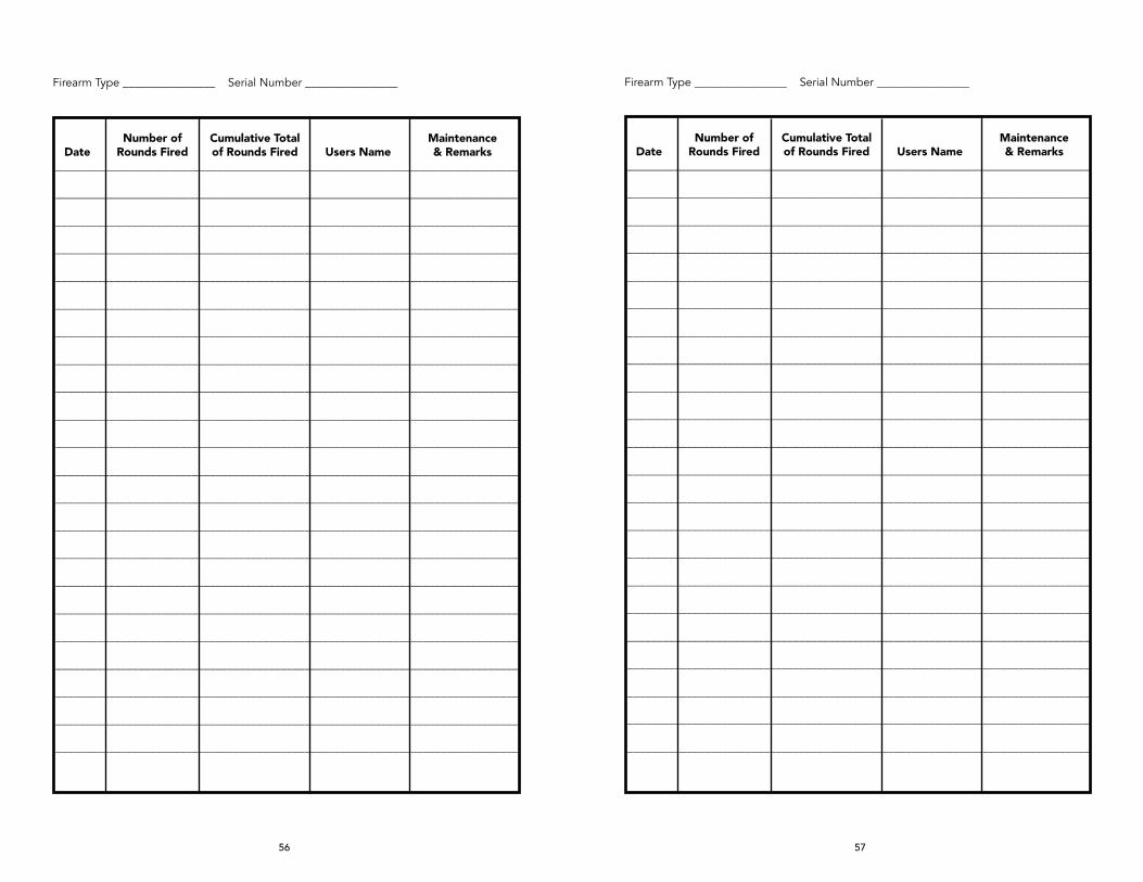
56 57
Firearm Type ________________ Serial Number ________________
Number of Cumulative Total Maintenance Date Rounds Fired of Rounds Fired Users Name & Remarks________________________________________________________________________________
________________________________________________________________________________
______________________________________________________________________________
______________________________________________________________________________
______________________________________________________________________________
______________________________________________________________________________
______________________________________________________________________________
______________________________________________________________________________
______________________________________________________________________________
______________________________________________________________________________
______________________________________________________________________________
______________________________________________________________________________
______________________________________________________________________________
______________________________________________________________________________
______________________________________________________________________________
______________________________________________________________________________
______________________________________________________________________________
______________________________________________________________________________
______________________________________________________________________________
______________________________________________________________________________
______________________________________________________________________________
______________________________________________________________________________

58
Firearm Type ________________ Serial Number ________________
Number of Cumulative Total Maintenance Date Rounds Fired of Rounds Fired Users Name & Remarks________________________________________________________________________________
________________________________________________________________________________
______________________________________________________________________________
______________________________________________________________________________
______________________________________________________________________________
______________________________________________________________________________
______________________________________________________________________________
______________________________________________________________________________
______________________________________________________________________________
______________________________________________________________________________
______________________________________________________________________________
______________________________________________________________________________
______________________________________________________________________________
______________________________________________________________________________
______________________________________________________________________________
______________________________________________________________________________
______________________________________________________________________________
______________________________________________________________________________
______________________________________________________________________________
______________________________________________________________________________
______________________________________________________________________________
______________________________________________________________________________

HECKLER & KOCH5675 Transport BoulevardColumbus, Georgia 31907United States of AmericaTel: (706) 568-1906Fax: (706) 568-9151USA Website: www.hk-usa.com
HECKLER & KOCHD-78722 Oberndorf/Neckar Postfach 1329GermanyTel: 011-49-7423/79-0Fax: 011-49-7423/2280Global Website: www.heckler-koch.com
HK
USA
-708116-07162013