mpr_300_user_manual_mpr-e.pdf
TRANSCRIPT

al
d-
AAe 1010
User Manu
MPR-e (Outdoor units: MPT-HC/MPT-HC V2/MPT-MC stanalone)
9500 MPR-E
3DB 18793 EAIssu
Rel. 3.0.0
December 2

Status: RELEASED
All rights reserved.Passing on and copying of this document,
use and communication of its contents is not permittedwithout written authorization from Alcatel-Lucent.
3DB 18793 EAAA Issue 1
Alcatel, Lucent, Alcatel-Lucent and the Alcatel-Lucent logo are trademarks of Alcatel-Lucent.
All other trademarks are the property of their respective owners.
The information presented is subject to change without notice. Alcatel-Lucent assumes no responsibility for inaccuracies contained herein.
Copyright © 2010 Alcatel-Lucent

TABLE OF CONTENTS
LIST OF FIGURES ......................................................................................................................... 5
LIST OF TABLES ........................................................................................................................... 9
PREFACE......................................................................................................................................... 11Preliminary Information.............................................................................................................. 11Applicability................................................................................................................................. 12Scope ........................................................................................................................................... 12History.......................................................................................................................................... 12Change notes .............................................................................................................................. 13Handbook Structure ................................................................................................................... 13General on Alcatel-Lucent Customer Documentation ............................................................ 14
1 SAFETY, EMC, EMF, ESD NORMS AND EQUIPMENT LABELLING ........................................ 191.1 Declaration of conformity to CE marking and Countries List ......................................... 201.2 Specific label for MPR equipment ...................................................................................... 211.3 Applicable standards and recommendations ................................................................... 211.4 Safety Rules ......................................................................................................................... 22
1.4.1 General Rules................................................................................................................. 221.4.2 Labels Indicating Danger, Forbiddance, Command........................................................ 23
1.5 Electromagnetic Compatibility (EMC norms).................................................................... 261.6 Equipment protection against electrostatic discharges .................................................. 271.7 Cautions to avoid equipment damage ............................................................................... 28
2 PRODUCT INFORMATION AND PLANNING ............................................................................. 292.1 9500 Family overview .......................................................................................................... 31
2.1.1 9500 MPR System Family .............................................................................................. 352.1.2 Family elements described in this User Manual ............................................................. 362.1.3 GEthernet Generic Device pre-requisities ...................................................................... 362.1.4 MPT-HC .......................................................................................................................... 362.1.5 MPT-HC V2..................................................................................................................... 402.1.6 MPT-MC.......................................................................................................................... 432.1.7 Antennas......................................................................................................................... 45
2.2 Radio capacity, channelling and modulation (MPT-HC/MPT-HC V2/MPT-MC)................ 462.3 Standard Features ............................................................................................................... 492.4 Radio Configurations .......................................................................................................... 492.5 Environmental and Electrical Characteristics................................................................... 50
2.5.1 General characteristics (MPT-HC/MPT-HC V2/MPT-MC)............................................... 502.5.2 MPT-HC/MPT-HC V2 characteristics .............................................................................. 522.5.3 MPT-MC characteristics.................................................................................................. 542.5.4 Radio performances ....................................................................................................... 542.5.5 General characteristics (Power Injector)......................................................................... 552.5.6 General characteristics (Power Extractor) ...................................................................... 55
2.6 Parts Lists............................................................................................................................. 562.6.1 Indoor items .................................................................................................................... 562.6.2 MPT-HC optical interface option ..................................................................................... 562.6.3 MPT-HC V2 external modules (mandatory) .................................................................... 562.6.4 MPT-HC with internal diplexer ........................................................................................ 572.6.5 MPT-HC V2 with internal diplexer ................................................................................... 592.6.6 MPT-MC with internal diplexer ........................................................................................ 612.6.7 MPT-HC/MPT-HC V2/MPT-MC with external diplexer (7/8 GHz) ................................... 63
2.7 Functional description ........................................................................................................ 672.7.1 MPT-HC .......................................................................................................................... 67
User Manual
Table of Contents
9500 MPR-E Rel. 3.0.0
3DB 18793 EAAA Issue 1 1/280

2.7.2 MPT-HC V2..................................................................................................................... 742.7.3 MPT-MC.......................................................................................................................... 752.7.4 Power Injector................................................................................................................. 762.7.5 Power Extractor .............................................................................................................. 772.7.6 Radio Transmission Features with MPT-HC/MPT-HC V2/MPT-MC................................ 782.7.7 NE IP Addresses ............................................................................................................ 802.7.8 TMN management .......................................................................................................... 802.7.9 Quality Of Services (QoS) .............................................................................................. 812.7.10 Synchronization ............................................................................................................ 82
3 NE MANAGEMENT BY SOFTWARE APPLICATION................................................................. 833.1 WebEML start ....................................................................................................................... 833.2 Tool bar ................................................................................................................................. 853.3 Alarm Synthesis................................................................................................................... 853.4 Domain Alarm Synthesis Area............................................................................................ 863.5 General Information on the Management State ................................................................ 863.6 Navigator area...................................................................................................................... 87
3.6.1 Commissioning ............................................................................................................... 883.6.2 Performance Monitoring ................................................................................................. 1083.6.3 Troubleshooting .............................................................................................................. 1193.6.4 Maintenance ................................................................................................................... 1223.6.5 Monitoring ....................................................................................................................... 123
4 INSTALLATION............................................................................................................................ 1294.1 Installation & Interconnection overview ............................................................................ 129
4.1.1 How to connect the MPT-HC to the battery .................................................................... 1334.2 Hardware Installation........................................................................................................... 134
4.2.1 Power consumption ........................................................................................................ 1344.2.2 MPT-HC Installation ........................................................................................................ 1354.2.3 MPT-HC V2 Installation................................................................................................... 1754.2.4 MPT-MC Installation........................................................................................................ 1874.2.5 Power Extractor .............................................................................................................. 2084.2.6 Power Injector................................................................................................................. 2094.2.7 Installation items ............................................................................................................. 2114.2.8 Antenna Alignment ......................................................................................................... 215
4.3 Software local copy ............................................................................................................. 2214.3.1 Getting Started................................................................................................................ 2224.3.2 PC Characteristics .......................................................................................................... 2224.3.3 Local copy of the Software Package (SWP) to the PC................................................... 2234.3.4 Local copy of the WebEML to PC................................................................................... 2244.3.5 Configure the PC Network Card for the connection to the NE........................................ 229
5 PROVISIONING............................................................................................................................ 2395.1 Option1: MPR-e will be configured through the PC ......................................................... 240
5.1.1 Pre requisites for the PC................................................................................................. 2405.1.2 MPT interconnection option ............................................................................................ 2405.1.3 Procedure ....................................................................................................................... 241
5.2 Option 2: MPR-e will be configured directly through GEthernet generic device........... 2455.2.1 Pre requisites for the GEthernet generic device ............................................................. 2455.2.2 Procedure ....................................................................................................................... 245
6 MAINTENANCE AND TROUBLE-CLEARING ............................................................................ 2476.1 Introduction.......................................................................................................................... 2476.2 Maintenance Philosophy..................................................................................................... 2486.3 Personal Computer (PC)/Laptop ........................................................................................ 248
User Manual
Table of Contents
9500 MPR-E Rel. 3.0.0
3DB 18793 EAAA Issue 12/280

6.4 Troubleshooting................................................................................................................... 2486.4.1 Before Going to Site Checklist ........................................................................................ 2486.4.2 PC Troubleshooting ........................................................................................................ 2496.4.3 Troubleshooting Basics................................................................................................... 2506.4.4 Troubleshooting Path Problems...................................................................................... 254
6.5 Equipment removal and replacement ................................................................................ 2566.5.1 MPT-HC removal and replacement................................................................................. 2566.5.2 MPT-HC V2 removal and replacement ........................................................................... 2566.5.3 MPT-MC removal and replacement ................................................................................ 256
6.6 Cleaning................................................................................................................................ 256
7 LINE–UP AND COMMISSIONING ............................................................................................... 2577.1 Introduction.......................................................................................................................... 258
7.1.1 General ........................................................................................................................... 2587.1.2 Safety–EMC–EMF–ESD norms and cautions to avoid equipment damage................... 2597.1.3 Conventions.................................................................................................................... 2597.1.4 Summary of the line–up, commissioning, and acceptance phases ................................ 2597.1.5 MCT connection.............................................................................................................. 2607.1.6 How to access the remot MPT........................................................................................ 261
7.2 Commissioning of STATION A – phase 1 (Turn up).......................................................... 2627.2.1 Turn–on preliminary operations ...................................................................................... 2627.2.2 Powering up the MPT ..................................................................................................... 263
7.3 Commissioning of STATION B – phase 1 (Turn up).......................................................... 2637.4 Fine antenna alignment and preliminary checks – Stations A & B................................. 264
7.4.1 Fine antenna alignment .................................................................................................. 2647.4.2 Preliminary checks.......................................................................................................... 264
7.5 End of commissioning phase 1 (Turn up) in STATION A ................................................. 2657.6 Commissioning station A – phase 2 (acceptance test) .................................................... 266
7.6.1 Installation and cabling visual inspection ........................................................................ 2677.6.2 System configuration ...................................................................................................... 2677.6.3 Ethernet Traffic QoS ....................................................................................................... 2687.6.4 NE configuration ............................................................................................................. 2697.6.5 Data/Time settings .......................................................................................................... 2697.6.6 Ethernet Traffic hop stability test..................................................................................... 270
7.7 Commissioning station B – Phase 2 (acceptance Test) ................................................... 2717.8 Final operations ................................................................................................................... 2717.9 Annex A: fine antenna alignment ....................................................................................... 271
ABBREVIATIONS ............................................................................................................................ 273
CUSTOMER DOCUMENTATION FEEDBACK.............................................................................. 279
User Manual
Table of Contents
9500 MPR-E Rel. 3.0.0
3DB 18793 EAAA Issue 1 3/280

User Manual
Table of Contents
9500 MPR-E Rel. 3.0.0
3DB 18793 EAAA Issue 14/280

LIST OF FIGURES
Figure 1. Multiservice Aggregation Layer ......................................................................................... 33Figure 2. Service Awareness ............................................................................................................ 33Figure 3. Packet Node ...................................................................................................................... 34Figure 4. Service-driven Packet Adaptive Modulation ...................................................................... 34Figure 5. 9500 MPR System Family ................................................................................................. 35Figure 6. 11 GHz MPT-HC (on the left) and 6 GHz MPT-HC (on the right)....................................... 37Figure 7. MPT-HC connection (electrical cable for traffic and coaxial cable for power supply) ........ 37Figure 8. MPT-HC connection through the Power Injector Box ........................................................ 38Figure 9. MPT-HC connection through the Power Injector Plug-in installed in the SAR.................. 38Figure 10. MPT-HC connection (optical cable for traffic and coaxial cable for power supply) .......... 39Figure 11. MPT-HC V2...................................................................................................................... 40Figure 12. MPT-HC V2 connection through the Power Injector Box................................................. 41Figure 13. MPT-HC V2 connection through the Power Injector Plug-in installed in the SAR............ 41Figure 14. MPT-HC V2 connection (optical cable for traffic and coaxial cable for power supply)..... 42Figure 15. MPT-MC........................................................................................................................... 43Figure 16. MPT-MC connection through the Power Injector Box...................................................... 44Figure 17. MPT-MC connection through the Power Injector Plug-in installed in the SAR................. 44Figure 18. MPT system..................................................................................................................... 68Figure 19. 11-38 GHz MPT-HC housing ........................................................................................... 68Figure 20. 6 GHz MPT-HC housing .................................................................................................. 68Figure 21. 7-8 GHz MPT-HC housing ............................................................................................... 69Figure 22. MPT-HC block diagram.................................................................................................... 69Figure 23. 7/8 GHz MPT-HC architecture ......................................................................................... 72Figure 24. 11 to 38 GHz MPT-HC architecture ................................................................................. 72Figure 25. MPT-HC V2 housing (6 GHz and 11 GHz to 38 GHz) ..................................................... 74Figure 26. 6 GHz and from 11 to 38 GHz MPT-MC housing............................................................. 75Figure 27. 7-8 GHz MPT-MC housing............................................................................................... 75Figure 28. Power Injector plug-in ...................................................................................................... 76Figure 29. Power Injector box ........................................................................................................... 76Figure 30. Power Injector front panel................................................................................................ 77Figure 31. Power Extractor ............................................................................................................... 77Figure 32. Available loopbacks ......................................................................................................... 79Figure 33. QoS in the MPT ............................................................................................................... 81Figure 34. Main view: System Overview........................................................................................... 84Figure 35. Inventory .......................................................................................................................... 88Figure 36. Software Download: Software Package versions ............................................................ 89Figure 37. Software download .......................................................................................................... 90Figure 38. Software Download: Active Software Package summary ................................................ 90Figure 39. Software Download: Stand-by Software Package summary............................................ 91Figure 40. Date/Time Configuration .................................................................................................. 92Figure 41. Site Information................................................................................................................ 93Figure 42. Protection Configuration .................................................................................................. 93Figure 43. Synchronization (PCR) .................................................................................................... 94Figure 44. Synchronization (SynchE) ............................................................................................... 94Figure 45. Synchronization (Internal)................................................................................................ 95Figure 46. Radio Configuration: FCM - RTPC .................................................................................. 97Figure 47. Radio Configuration: FCM - ATPC................................................................................... 98Figure 48. Radio Configuration: ACM - RTPC .................................................................................. 98Figure 49. Advanced Radio Configuration ........................................................................................ 99Figure 50. Ethernet Traffic QoS ........................................................................................................ 100Figure 51. IEEE 802.1p..................................................................................................................... 101Figure 52. DiffServ ............................................................................................................................ 101
User Manual
List of Figures
9500 MPR-E Rel. 3.0.0
3DB 18793 EAAA Issue 1 5/280
Figure 53. EtherType classification ................................................................................................... 102Figure 54. Scheduling Algorithms ..................................................................................................... 103Figure 55. Network Interfaces........................................................................................................... 104Figure 56. Static Routing................................................................................................................... 105Figure 57. Trusted SNMP Managers ................................................................................................ 106Figure 58. Manager registration........................................................................................................ 106Figure 59. Backup / Restore ............................................................................................................. 107Figure 60. Performance History File Upload..................................................................................... 109Figure 61. Counter Thresholds ......................................................................................................... 109Figure 62. 15Min Counter activation ................................................................................................. 110Figure 63. 15Min Counter ................................................................................................................. 110Figure 64. 15Min Counter history...................................................................................................... 111Figure 65. 15Min Counter deactivation ............................................................................................. 111Figure 66. Adaptive Modulation counter activation ........................................................................... 112Figure 67. 15Min Counter ................................................................................................................. 113Figure 68. 15Min Counter history...................................................................................................... 113Figure 69. 15Min Counter deactivation ............................................................................................. 114Figure 70. Ethernet: Qos Counters ................................................................................................... 115Figure 71. Qos Counters example for Queue 1 ................................................................................ 116Figure 72. Ethernet: Traffic Port Counters ........................................................................................ 117Figure 73. Traffic Port Counters example ......................................................................................... 118Figure 74. Inventory .......................................................................................................................... 119Figure 75. Loopback activation ......................................................................................................... 120Figure 76. ACM Manual Management .............................................................................................. 120Figure 77. ATPC Manual Management (ANSI market only) ............................................................. 121Figure 78. Maintenance .................................................................................................................... 122Figure 79. Alarms.............................................................................................................................. 124Figure 80. Power measurements...................................................................................................... 124Figure 81. Power measurements...................................................................................................... 125Figure 82. Modem measurements .................................................................................................... 126Figure 83. Modem measurements .................................................................................................... 127Figure 84. Events.............................................................................................................................. 128Figure 85. Station interconnections with MPT-MC (Power Injector Box)........................................... 129Figure 86. Station interconnections with MPT-MC (Power Injector Plug-in)...................................... 130Figure 87. Station interconnections with MPT-HC............................................................................. 130Figure 88. Station interconnections with MPT-HC with Power Injector Box/Power Extractor ........... 131Figure 89. Station interconnections with MPT-HC with Power Injector Plug-in/Power Extractor ...... 131Figure 90. Station interconnections with MPT-HC V2 (Power Injector Box)...................................... 132Figure 91. Station interconnections with MPT-HC V2 (Power Injector Plug-in)................................. 132Figure 92. Station interconnections with MPT-HC V2 ....................................................................... 133Figure 93. MPT-HC directly connected to the battery ....................................................................... 133Figure 94. Views of MPT-HC with embedded diplexer (11-38 GHz) ................................................. 136Figure 95. Views of MPT-HC with embedded diplexer (6 GHz) ........................................................ 137Figure 96. Views of MPT-HC with external diplexer (7 GHz and 8 GHz) .......................................... 137Figure 97. Views of MPT-HC with embedded diplexer (11-38 GHz) ................................................. 139Figure 98. Views of MPT-HC with external diplexer (7 GHz and 8 GHz) .......................................... 140Figure 99. Views of MPT-HC with embedded diplexer (6 GHz) ........................................................ 141Figure 100. Composition of MPT-HC with external diplexer ............................................................. 142Figure 101. MPT-HC TRANSCEIVER and BRANCHING boxes coupling surfaces ......................... 143Figure 102. 6-7-8 GHz MPT-HC BRANCHING box mistake-proofing............................................... 143Figure 103. Label affixed on the MPT-HC and MPT-HC TRANSCEIVER box.................................. 144Figure 104. Label affixed inside the MPT-HC BRANCHING box ...................................................... 145Figure 105. Example of integrated antenna Pole Mounting (with antenna and nose adapter) ...................................................................................................... 148
User Manual
List of Figures
9500 MPR-E Rel. 3.0.0
3DB 18793 EAAA Issue 16/280

Figure 106. "Pole Mounting for Remote ODU" Installation kit (3DB10137AAXX)............................ 149Figure 107. Example of antenna polarization change (“1+0” MPT-HC integrated antenna) ............. 150Figure 108. Putting silicone grease on O-ring before MPT-HC insertion .......................................... 151Figure 109. MPT-HC 1+0 installation for integrated antenna (11-38 GHz) ....................................... 151Figure 110. MPT-HC 1+0 installation for integrated antenna (6-7-8 GHz: vertical polarization) ....... 152Figure 111. MPT-HC 1+0 installation for integrated antenna (6-7-8 GHz: horizontal polarization) ... 152Figure 112. "Pole Mounting for Remote ODU" installation................................................................ 153Figure 113. Putting silicone grease on O-ring before MPT-HC insertion .......................................... 153Figure 114. MPT-HC 1+0 installation for not integrated antenna (11-38 GHz with pole mounting P/N 3DB 10137 AAAB) ..................................................................................................................... 154Figure 115. MPT-HC 1+0 installation for not integrated antenna (6-7-8 GHz with pole mounting P/N 3DB10137AAXX) ....................................................................................................................... 154Figure 116. Locations for Cable Grounds ......................................................................................... 171Figure 117. Views of MPT-HC V2 with embedded diplexer (6 GHz and 11-38 GHz)........................ 176Figure 118. RPS module................................................................................................................... 178Figure 119. XPIC + RPS module ...................................................................................................... 178Figure 120. External module installed............................................................................................... 179Figure 121. Correct screw position ................................................................................................... 179Figure 122. Views of MPT-HC V2 with embedded diplexer (6 GHz and 11-38 GHz) ....................... 181Figure 123. Views of MPT-HC V2 with external diplexer (7 GHz and 8 GHz)................................... 182Figure 124. Label affixed on the MPT-HC V2 and MPT-HC V2 TRANSCEIVER box....................... 183Figure 125. Label affixed inside the MPT-HC V2 BRANCHING box................................................. 184Figure 126. Q-XCO to Q-XCO Fiber cord ......................................................................................... 185Figure 127. Views of MPT-MC with embedded diplexer (6 and 11-38 GHz)..................................... 188Figure 128. Views of MPT-MC with external diplexer (7 GHz and 8 GHz)........................................ 189Figure 129. Views of MPT-MC with embedded diplexer (6 and 11-38 GHz)..................................... 190Figure 130. Views of MPT-MC with external diplexer (7 GHz and 8 GHz)........................................ 190Figure 131. Composition of MPT-MC with external diplexer ............................................................. 191Figure 132. MPT-MC TRANSCEIVER and BRANCHING boxes coupling surfaces ......................... 192Figure 133. 7-8 GHz MPT-MC BRANCHING box mistake-proofing ................................................. 193Figure 134. Label affixed on the MPT-MC and MPT-MC TRANSCEIVER box................................. 194Figure 135. Label affixed inside the MPT-MC BRANCHING box...................................................... 195Figure 136. Example of antenna polarization change (“1+0” MPT-MC integrated antenna)............. 198Figure 137. Putting silicone grease on O-ring before MPT-MC insertion.......................................... 199Figure 138. MPT-MC 1+0 installation for integrated antenna (6 GHz and 11-38 GHz)..................... 199Figure 139. MPT-MC 1+0 installation for integrated antenna (7-8 GHz: vertical polarization) .......... 200Figure 140. MPT-MC 1+0 installation for integrated antenna (7-8 GHz: horizontal polarization)...... 200Figure 141. "Pole Mounting for Remote ODU" installation................................................................ 201Figure 142. Putting silicone grease on O-ring before MPT-MC insertion.......................................... 201Figure 143. MPT-MC 1+0 installation for not integrated antenna (with pole mounting P/N 3DB 10137 AAAB) ..................................................................................................................... 202Figure 144. Short kit plug R2CT ....................................................................................................... 203Figure 145. Short kit plug R2CT items.............................................................................................. 203Figure 146. Power Injector box + Bracket 3DB77008ACXX............................................................. 209Figure 147. Grounding ...................................................................................................................... 209Figure 148. Power supply connector ................................................................................................ 209Figure 149. Power Injector plug-in .................................................................................................... 210Figure 150. MPT/AWY Service Cord ................................................................................................ 217Figure 151. Indicative head-on signal pattern for a parabolic antenna ............................................. 219Figure 152. Example Tracking Path Signals ..................................................................................... 220Figure 153. Example Tracking Path Signals on the First Side Lobe................................................. 220Figure 154. Ethernet Traffic hop stability test with MPT-MC ............................................................. 270Figure 155. Ethernet Traffic hop stability test with MPT-HC.............................................................. 270
User Manual
List of Figures
9500 MPR-E Rel. 3.0.0
3DB 18793 EAAA Issue 1 7/280

User Manual
List of Figures
9500 MPR-E Rel. 3.0.0
3DB 18793 EAAA Issue 18/280

LIST OF TABLES
Table 1. Radio capacity, channelling scheme and modulation (Static Modulation) ........................... 46Table 2. Radio capacity, channelling scheme and modulation (Adaptive Modulation)...................... 48Table 3. Indoor item codes................................................................................................................ 56Table 4. CD-ROM Software codes.................................................................................................... 56Table 5. MPT-HC option.................................................................................................................... 56Table 6. MPT-HC V2 external modules............................................................................................. 56Table 7. MPT-HC codes with internal diplexer .................................................................................. 57Table 8. MPT-HC V2 codes with internal diplexer ............................................................................. 59Table 9. MPT-MC codes with internal diplexer .................................................................................. 61Table 10. 7 GHz MPT-MC codes with external diplexer.................................................................... 63Table 11. 7 GHz MPT-HC codes with external diplexer .................................................................... 63Table 12. 7 GHz MPT-HC V2 codes with external diplexer............................................................... 64Table 13. 7 GHz MPT-HC V2 High Power codes with external diplexer ........................................... 64Table 14. 7 GHz Branching assemblies (for MPT-HC and MPT-MC................................................. 64Table 15. 8 GHz MPT-MC codes with external diplexer.................................................................... 65Table 16. 8 GHz MPT-HC codes with external diplexer .................................................................... 65Table 17. 8 GHz MPT-HC V2 codes with external diplexer............................................................... 65Table 18. 8 GHz MPT-HC V2 High Power codes with external diplexer ........................................... 65Table 19. 8 GHz Branching assemblies (for MPT-HC and MPT-MC)................................................ 66Table 20. RSSI Table ........................................................................................................................ 73Table 21. Waveguide Flange Data .................................................................................................... 73Table 22. MPT-HC external interfaces ............................................................................................. 138Table 23. RF interface...................................................................................................................... 138Table 24. MPT-HC Output flanges with external antenna ................................................................. 168Table 25. 6-7-8GHz Flextwist waveguide.......................................................................................... 169Table 26. 11-38GHz Flextwist waveguide ......................................................................................... 169Table 27. MPT-HC V2 external interfaces........................................................................................ 180Table 28. RF interface...................................................................................................................... 180Table 29. MPT-MC external interfaces............................................................................................. 189Table 30. RF interface...................................................................................................................... 189Table 31. Provisioning option ............................................................................................................ 239Table 32. Sumary table ..................................................................................................................... 240Table 33. MPT-HC/MPT-HC V2 Alarm Matrix ................................................................................... 250Table 34. MPT-MC Alarm Matrix ....................................................................................................... 252Table 35. Test and commissioning instruments ................................................................................ 258
User Manual
List of Tables
9500 MPR-E Rel. 3.0.0
3DB 18793 EAAA Issue 1 9/280

User Manual
List of Tables
9500 MPR-E Rel. 3.0.0
3DB 18793 EAAA Issue 110/280

PREFACE
Preliminary Information
WARRANTY
Any warranty must be referred exclusively to the terms of the contract of sale of the equipment to which this handbook refers to.
Alcatel–Lucent makes no warranty of any kind with regards to this manual, and specifically disclaims the implied warranties of merchantability and fitness for a particular purpose. Alcatel–Lucent will not be liable for errors contained herein or for damages, whether direct, indirect, consequential, inci-dental, or special, in connection with the furnishing, performance, or use of this material.
INFORMATION
The product specification and/or performance levels contained in this document are for information purposes only and are subject to change without notice. They do not represent any obligation on the part of Alcatel–Lucent.
COPYRIGHT NOTIFICATION
The technical information of this manual is the property of Alcatel–Lucent and must not be copied, reproduced or disclosed to a third party without written consent.
SAFETY RECOMMENDATIONS
The safety recommendations here below must be considered to avoid injuries on persons and/or damage to the equipment:
1) Service PersonnelInstallation and service must be carried out by authorized persons having appropriate technical training and experience necessary to be aware of hazardous operations during installation and service, so as to prevent any personal injury or danger to other persons, as well as prevent-damaging the equipment.
2) Access to the EquipmentAccess to the Equipment in use must be restricted to Service Personnel only.
3) Safety RulesRecommended safety rules are indicated in Chapter 1 from page 19.
User Manual
Preface
9500 MPR-E Rel. 3.0.0
3DB 18793 EAAA Issue 1 11/280

Local safety regulations must be used if mandatory. Safety instructions in this handbook should be used in addition to the local safety regulations. In case of conflict between safety instructions stated in this manual and those indicated in local regulations, mandatory local norms will pre-vail. Should not local regulations be mandatory, then safety rules stated in this manual will pre-vail.
SERVICE PERSONNEL SKILL
Service Personnel must have an adequate technical background on telecommunications and in par-ticular on the equipment subject of this handbook.
An adequate background is required to properly install, operate and maintain equipment. The fact of merely reading this handbook is considered as not enough.
Applicability
This handbook applies to the following product–release:
PRODUCT
9500 MPR-E
PRODUCT RELEASE
MPR-e 3.0.0
Scope
This document aims to describe the hardware and software functionalities.
This document is intended to the technicians involved in Planning, in Operation and Maintenance and in Commissioning.
History
ISSUE DATE DESCRIPTIONS
01 December 2010
User Manual
Preface
9500 MPR-E Rel. 3.0.0
3DB 18793 EAAA Issue 112/280

Change notes
Handbook Structure
This handbook has been edited according to the Alcatel-Lucent standardized “drawing-up guides" com-plying with such suggestion.
This handbook is divided into the main topics described in the table of contents:
PREFACE It contains general information as preliminary information, hand-book scope, history. Furthermore, it describes the handbook struc-ture and the customer documentation.
SAFETY This section includes all the safety instructions.
PRODUCT INFORMATIONAND PLANNING
This section provides the equipment description (at system, MSS-1c and Outdoor levels), introduces the basic information regarding the 9500 MPR-e HW architecture, and gives its technical charac-teristics.
NE MANAGEMENT BYSOFTWARE APPLICATIONS
This section gives the description and use of the SW tools available for the NE management.
INSTALLATION This section provides whole information regarding Equipment hard-ware installation. Moreover, it contains the whole operative information on:– provisioning of equipment items (P/Ns, equipping rules)– their physical position in the system– unit assembly and front panel drawings, with the description
on the access point usage (connectors, visual indicators, but-tons).
This section provides also the whole operative instructions for the preparation of the Craft Terminal for the Line–Up and Commission-ing of the two NEs making up the radio link.
PROVISIONING This section gives all the instructions to provision (to configure) the NE.
MAINTENANCE AND TROUBLE-CLEARING
This section contains the whole logical and operative information for the equipment maintenance and system upgrade.
LINE-UP AND COMMISSIONING
This section provides all the instructions for the line-up and com-missioning of the NE.
ABBREVIATIONS The abbreviation list is supplied.
CUSTOMER DOCUMENTA-TION FEEDBACK
It contains info regarding customer opinions collection about this documentation.
User Manual
Preface
9500 MPR-E Rel. 3.0.0
3DB 18793 EAAA Issue 1 13/280

General on Alcatel-Lucent Customer Documentation
This paragraph describes in general the Alcatel–Lucent Customer Documentation system, details the association between the product levels and the associated documentation, and explains Customer Doc-umentation characteristics as well as the policies for its delivery and updating.
Customer–Independent Standard Customer Documentation
a) DefinitionStandard Customer Documentation, referred to hereafter, must be always meant as plant–indepen-dent and is always independent of any Customization.Plant–dependent and/or Customized documentation, if envisaged by the contract, is subjected to commercial criteria as far as contents, formats and supply conditions are concerned.N.B. Plant–dependent and Customized documentation is not described here.
b) Aims of standard Customer DocumentationStandard system, hardware and software documentation is meant to give the Customer personnel the possibility and the information necessary for installing, commissioning, operating, and maintain-ing the equipment according to Alcatel–Lucent Laboratory design and Installation Dept. choices. In particular:• the contents of the chapters associated to the software applications focus on the explanation
of the man–machine interface and of the operating procedures allowed by it;• maintenance is described down to faulty PCB location and replacement.N.B. No supply to Customers of design documentation (like PCB hardware design andproduction documents and files, software source programs, programming tools, etc.) is envisaged.
Product levels and associated Customer Documentation
a) ProductsA “product” is defined by the network hierarchical level where it can be inserted and by the whole of performances and services that it is meant for.E.g. 9500 MPR is a product.
b) Product-releasesA ”product” evolves through successive “product–releases”, which are the real products marketed for their delivery at a certain ”product–release” availability date. A certain ”product–release” performs more functionalities than the previous one.E.g. Rel.1.0 and Rel.2.0 are two successive “product–releases” of the same “product”.A “product–release” comprehends a set of hardware components and at least one “Software Pack-age” (SWP); as a whole, they identify the possible network applications and the equipment perfor-mances that the specific “product–release” has been designed, engineered, and marketed for.
c) Configurations and Network ElementsIn some cases, a “product–release” includes different possible “configurations” which are distin-guished from one another by different “Network Element” (NE) types and, from the management point of view, by different SWPs.
d) SWP releases, versions, and CD–ROMs• Each SWP is distributed by means of a specific SWP CD–ROM.• A SWP is identified by its “Denomination”, “P/N” (Part Number) and “CS” (Change Status), that
are printed on the CD–ROM’s label:– the first and second digits of the “Denomination” (e.g. 2.0) correspond to the “HW product–
release” number;– the third digit of the of the “Denomination” (e.g. 2.0.2) identifies the Version Level of the
SWP.
User Manual
Preface
9500 MPR-E Rel. 3.0.0
3DB 18793 EAAA Issue 114/280

• A SWP with new Version Level, providing main features in addition to those of the previous Ver-sion Level SWP, is distributed by means of a SWP CD–ROM having new “Denomination”,“P/N” (Part Number), and “CS” restarting from 01
• A SWP patch version, if any, is created to correct SW bugs, and/or to add minor features, andis distributed by means of a SWP CD–ROM, that can be identified:– by the same “P/N” of the former CD–ROM, but with an incremented “CS” number
(e.g.CS=02 instead of previous CS=01)– or by a new “P/N”, and “CS” restarting from 01.
Handbook Updating
The handbooks associated to the "product-release" are listed in “History“ on page 12.
Each handbook is identified by: – the name of the "product–release" (and "version" when the handbook is applicable to the versions
starting from it, but not to the previous ones), – the handbook name, – the handbook Part Number, – the handbook edition (usually first edition=01),– the handbook issue date. The date on the handbook does not refer to the date of print but to the date
on which the handbook source file has been completed and released for the production.
Changes introduced in the same product–release (same handbook P/N)
The edition and date of issue might change on future handbook versions for the following reasons:
– only the date changes (pointed out in the Table of Contents) when modifications are made to the edi-torial system not changing the technical contents of the handbook.
– the edition, hence the date, is changed because modifications made concern technical contents. In this case:
• the changes with respect to the previous edition are listed in “History” on page 12;• in affected chapters, revision bars on the left of the page indicate modifications in text and draw-
ings.
Changes concerning the technical contents of the handbook cause the edition number increase (e.g. from Ed.01 to Ed.02). Slight changes (e.g. for corrections) maintain the same edition but with the addition of a version character (e.g. from Ed.02 to Ed.02A). Version character can be used for draft or proposal edi-tions.
NOTES FOR HANDBOOKS RELEVANT TO SOFTWARE APPLICATIONSHandbooks relevant to software applications (typically the Operator's Handbooks) are not modified unless the new software "version" distributed to Customers implies man-machine interface changes or in case of slight modifications not affecting the understanding of the explained procedures.
Moreover, should the screen prints included in the handbook contain the product–release's "version" marking, they are not replaced in the handbooks related to a subsequent version, if the screen contents are unchanged.
Supplying updated handbooks to Customers
Supplying updated handbooks to Customers who have already received previous issues is submitted to commercial criteria.By updated handbook delivery it is meant the supply of a complete copy of the handbook new issue (sup-plying errata-corrige sheets is not envisaged).
User Manual
Preface
9500 MPR-E Rel. 3.0.0
3DB 18793 EAAA Issue 1 15/280

Changes due to new product version
A new product version changes the handbook P/N and the edition starts from 01. In this case the modified parts of the handbook are not listed.
Customer documentation on CD-ROM
In the following by 'CD-ROM' it is meant 'Customer Documentation on CD-ROM'
Contents, creation and production of a CD-ROM
In most cases, a CD-ROM contains in read-only eletronic format the documentation of one product-release(-version) and for a certain language.In some other cases, the same CD-ROM can contain the documentation of different product-release(-ver-sion)s for a certain language.
As a general rule:
– CD-ROMs for Network Management products do not contain:
• the Installation Guides
• the documentation of system optional features that Customers could not buy from Alcatel-Lucent together with the main applicative SW.
– CD-ROMs for Network Elements products do not contain:
• the documentation of system optional features (e.g. System Installation Handbooks related to racks that Customers could not buy from Alcatel-Lucent together with the main equipment).
A CD-ROM is obtained collecting various handbooks and documents in .pdf format. Bookmarks and hyperlinks make the navigation easier. No additional information is added to each handbook, so that the documentation present in the CD-ROMs is exactly the same the Customer would receive on paper.
The files processed in this way are added to files/images for managing purpose and a master CD-ROM is recorded.
Suitable checks are made in order to have a virus-free product.
After a complete functional check, the CD-ROM image is electronically transferred to the archive of the Production Department, so that the CD-ROM can be produced and delivered to Customers.
Use of the CD-ROM
The CD-ROM can be used both in PC and Unix WS environments.
The CD-ROM starts automatically with autorun and hyperlinks from the opened “Index" document permit to visualize the .pdf handbooksOther hyperlinks permit to get, from the Technical handbooks, the specific .pdf setting documents.
In order to open the .pdf documents Adobe Acrobat Reader Version 4.0 (minimum) must have been installed on the platform.The CD-ROM doesn't contain the Adobe Acrobat Reader program. The Customer is in charge of getting and installing it.ReadMe info is present on the CD-ROM to this purpose.
Then the Customer is allowed to read the handbooks on the PC/WS screen, using the navigation and zooming tools included in the tool, and to print selected parts of the documentation through a local printer.
User Manual
Preface
9500 MPR-E Rel. 3.0.0
3DB 18793 EAAA Issue 116/280

CD-ROM identification
Each CD-ROM is identified:
1) by external identifiers, that are printed on the CD-ROM upper surface:– the name of the "product-release(s)" (and "version" if applicable) – a writing indicating the language(s),– the CD-ROM Part Number), – the CD-ROM edition (usually first edition=01)
2) and, internally, by the list of the source handbooks and documents (P/Ns and editions) by whose collection and processing the CD-ROM itself has been created.
CD-ROM updating
The list of source handbook/document P/Ns-editions indicated in previous para. point 2) , in association with the CD-ROM's own P/N-edition, is also loaded in the Alcatel-Information-System as a structured list.Whenever a new edition of any of such handbooks/documents is released in the Alcatel-Lucent archive system, a check in the Alcatel-Information-System is made to identify the list of CD-ROMs that must be updated to include the new editions of these handbooks/documents.This causes the planning and creation of a new edition of the CD-ROM.
Updating of CD-ROMs always follows, with a certain delay, the updating of the single handbooks com-posing the collection.
User Manual
Preface
9500 MPR-E Rel. 3.0.0
3DB 18793 EAAA Issue 1 17/280

User Manual
Preface
9500 MPR-E Rel. 3.0.0
3DB 18793 EAAA Issue 118/280

1 Safety, EMC, EMF, ESD Norms and Equipment Labelling
This chapter describes the equipment labelling and the norms mandatory or suggested that must be con-sidered to avoid injuries on persons and/or damage to the equipment.
This chapter is organized as follows:
– Declaration of conformity to CE marking and Countries List
– Specific label for MPR equipment
– Applicable standards and recommendations
– Safety Rules
– Electromagnetic Compatibility (EMC norms)
– Equipment protection against electrostatic discharges
– Cautions to avoid equipment damage
User Manual
Safety, EMC, EMF, ESD Norms and Equipment Label-
9500 MPR-E Rel. 3.0.0
3DB 18793 EAAA Issue 1 19/280

1.1 Declaration of conformity to CE marking and Countries List
Indication of the countries where the equipment is intended to be used: Austria (AT) - Belgium (BE) - Bulgaria (BG) - Switzerland/Liechtenstein (CH) - Cyprus (CY) - Czech Republic (CZ) - Germany (DE) - Denmark (DK) - Estonia (EE) - Finland (FI) - France (FR) - Greece (GR) - Hungary (HU) – Italy (IT) - Ireland (IE) - Iceland (IS) - Lithuania (LT) – Luxembourg (LU) - Latvia (LV) - Malta (MT) - Netherlands (NL) - Norway (NO) –Poland (PL) – Portugal (PT) - Romania (RO) – Spain (SP) - Sweden (SE) - Slovenia (SI) - Slovak Republic (SK) -United Kingdom (UK)
Indication of the intended use of the equipment: Point to Point PDH/Ethernet Transport radio Link
User Manual
Safety, EMC, EMF, ESD Norms and Equipment Label-
9500 MPR-E Rel. 3.0.0
3DB 18793 EAAA Issue 120/280

1.2 Specific label for MPR equipment
The label is sticked on the MPT-HC/MPT-HC V2/MPT-MC.
Field Field Name Note
A Alcatel-Lucent Logo
B Equipment acronym
C Power Supply range -28 V / -58 V
D Current range 1.6 A / 0.8 A for MPT-HC/MPT-MC1.5 A / 0.7 A for MPT-HC V2
E European Community Logo
F Not harmonized frequency logo
G WEEE Logo
H Electrostatic Device Logo
1.3 Applicable standards and recommendations
1999/5/CE of 09 March 1999
Safety: EN 60950, EN 60825-1, EN 60825-2, EN 50385
EMC: EN 301 489-1, EN 301 489-4
Spectrum: EN 302 217-2-2
User Manual
Safety, EMC, EMF, ESD Norms and Equipment Label-
9500 MPR-E Rel. 3.0.0
3DB 18793 EAAA Issue 1 21/280

1.4 Safety Rules
1.4.1 General Rules
Before carrying out any installation, turn-on, tests or operation and maintenance operations, read carefully the related sections of this Manual, in particular:
– Hardware Installation
– Commissioning
– Maintenance and Upgrade
Observe safety rules
– When equipment is operating nobody is allowed to have access inside on the equipment parts which are protected with Cover Plate Shields removable with tools.
– In case of absolute need to have access inside, on the equipment parts when it is operating this is allowed exclusively to service personnel, where for Service Personnel or Technical assistance is meant: • "personnel which has adequate Technical Knowledge and experience necessary to be aware
of the danger that he might find in carrying out an operation and of the necessary measure-ments to reduce danger to minimum for him and for others".
• The Service Personnel can only replace the faulty units with spare parts. • The Service Personnel is not allowed to repair: hence the access to the parts no specified is
not permitted. • The keys and/or the tools used to open doors, hinged covers to remove parts which give access
to compartments in which are present high dangerous voltages must belong exclusively to the service personnel.
– For the eventual cleaning of the external parts of the equipment, absolutely do not use any inflam-mable substance or substances which in some way may alter the markings, inscriptions ect.
– It is recommended to use a slightly wet cleaning cloth.
The Safety Rules stated in the handbook describe the operations and/or precautions to observe to safe-guard service personnel during the working phases and to guarantee equipment safety, i.e., not exposing persons, animals, things to the risk of being injured/damaged.
Whenever the safety protection features have been impaired, REMOVE POWER.
To cut off power proceed to switch off the power supply units as well as cut off power station upstream (rack or station distribution frame).
The safety rules described in this handbook are distinguished by the following symbol and statement:
User Manual
Safety, EMC, EMF, ESD Norms and Equipment Label-
9500 MPR-E Rel. 3.0.0
3DB 18793 EAAA Issue 122/280

1.4.2 Labels Indicating Danger, Forbiddance, Command
It is of utmost importance to follow the instructions printed on the labels affixed to the units and assemblies.
– dangerous electrical voltages – harmful optical signals – risk of explosion – moving mechanical parts – heat-radiating Mechanical Parts – microwave radiations
Pay attention to the information stated in the following, and proceed as instructed.
The symbols presented in following paragraphs are all the possible symbols that could be present on Alca-tel-Lucent equipment, but are not all necessarily present on the equipment this handbook refers to.
Dangerous Electrical Voltages
[1] Labeling
The following warning label is affixed next to dangerous voltages (>42.4 Vp; >60 Vdc).
If it is a Class 1 equipment connected to mains, then the label associated to it will state that the equip-ment will have to be grounded before connecting it to the power supply voltage, e.g.:
[2] Safety instructions
DANGER! Possibility of personal injury:
Carefully observe the specific procedures for installation / turn-up and commissioning / maintenance of equipment parts where D.C. power is present, described in the relevant installation / turn-up and commissioning / maintenance documents and the following general rules:
• Personal injury can be caused by -48VDC. Avoid touching powered terminals with any exposed part of your body.
• Short circuiting, low-voltage, low-impedance, DC circuits can cause severe arcing that can result in burns and/or eye damage. Remove rings, watches, and other metal jewelry before working with primary circuits. Exercise caution to avoid shorting power input terminals.
Note
User Manual
Safety, EMC, EMF, ESD Norms and Equipment Label-
9500 MPR-E Rel. 3.0.0
3DB 18793 EAAA Issue 1 23/280

Risks of Explosions: labeling and safety instructions
This risk is present when batteries are used, and it is signaled by the following label:
Therefore, slits or apertures are made to let air circulate freely and allow dangerous gasses to down flow (battery-emitted hydrogen). A 417-IEC-5641 Norm. compliant label is affixed next to it indicating that the openings must not be covered up.
Moving Mechanical Parts: labeling and safety instructions
The following warning label is affixed next to fans or other moving mechanical parts:
Before carrying out any maintenance operation see that all the moving mechanical parts have been stopped.
Equipment connection to earth
Terminals for equipment connection to earth , to be done according to international safety standards, are pointed out by the suitable symbol:
The position of earth connection terminals is specified in the Hardware Installation section.
User Manual
Safety, EMC, EMF, ESD Norms and Equipment Label-
9500 MPR-E Rel. 3.0.0
3DB 18793 EAAA Issue 124/280

Heat-radiating Mechanical Parts: labeling and safety instructions
The presence of heat-radiating mechanical parts is indicated by the following warning label in compliancy with IEC 417 Norm, Fig.5041:
DANGER! Possibility of personal injury:
Carefully observe the specific procedures for installation / turn-up and commissioning / maintenance of equipment parts where heat-radiating mechanical parts are present, described in the relevant installation / turn-up and commissioning / maintenance documents and the following general rule:
Personal injury can be caused by heat. Avoid touching powered terminals with any exposed part of your body.
Optical safety
The equipment contains Class 1 laser component according to IEC 60825-1 (par. 5).
CLASS 1 LASER PRODUCT
The laser source is placed in the optional SFP plug-in, which has to be installed in the Core-E unit. The laser source is placed in the left side of the SFP plug-in.
According to the IEC 60825-1 the explanatory label is not sticked on the equipment due to the lack of space.
Microwave radiations (EMF norms)
Equipment emitting RF power (Reminder from site preparation procedure):
The site must be compliant with ICNIRP guidelines or local regulation if more restrictive.
The following rules should be strictly applied by Customer:
– Non authorized persons should not enter the compliance boundaries, if any, for the general public.
– Compliance RF boundaries, if any, related to Electro Magnetic Field exposure must be marked.
– Workers should be allowed to switch-off the power if they have to operate inside compliance bound-aries.
– Assure good cable connection.
– Install the antenna as high as possible from floor or area with public access ( if possible the cylinder delimitating the compliance boundaries, if any, or the cylinder corresponding to the transmission area directly in front of antenna with the same diameter as the antenna, more than 2 meters high).
User Manual
Safety, EMC, EMF, ESD Norms and Equipment Label-
9500 MPR-E Rel. 3.0.0
3DB 18793 EAAA Issue 1 25/280

– Install the antenna as far as possible from other existing equipment emitting RF power.
Anyway remind that someone standing in front of the 9500 MPR antenna may cause traffic shutdown.
Place the relevant stickers:
EMF emission warning sign
On the site when applicable (when people can cross the compliance boundaries and/or the transmission area of the antenna, i.e. roof top installation)
– Warning label "Do not stand on the antenna axis"
On the mast (front side)
– EMF emission warning sign (Yellow and black) to be placed at bottom of antenna, visible by some-one moving in front of the antenna (roof top installation)
On the antenna (rear side)
– EMF emission warning sign, placed on the antenna.
1.5 Electromagnetic Compatibility (EMC norms)
The equipment's EMC norms depend on the type of installation being carried out (cable termination, grounding etc.,) and on the operating conditions (equipment, setting options of the electrical/electronic units, presence of dummy covers, etc.).
Before carrying out any installation, turn-on, tests & operation and maintenance operations, read carefully the related sections of this Manual, in particular:
– Hardware Installation
– Maintenance and Upgrade
The norms set down to guarantee EMC compatibility, are distinguished inside this Manual by the symbol and term:
EMC Norms
[1] EMC General Norms - Installation
• All connections (towards the external source of the equipment) made with shielded cables use only cables and connectors suggested in this Manual or in the relevant Plant Documentation, or those specified in the Customer's "Installation Norms" (or similar documents)
• Shielded cables must be suitably terminated
• Install filters outside the equipment as required
User Manual
Safety, EMC, EMF, ESD Norms and Equipment Label-
9500 MPR-E Rel. 3.0.0
3DB 18793 EAAA Issue 126/280

• Ground connect the equipment utilizing a conductor with proper diameter and impedance
• Mount shields (if utilized), previously positioned during the installation phase, but not before having cleaned and degrease it
• Before inserting the shielded unit proceed to clean and degrease all peripheral surfaces (con-tact springs and connection points, etc.)
• Screw fasten the units to the subrack
• To correctly install EMC compatible equipment follow the instructions given
[2] EMC General Norms - Turn-on, Tests & Operation
• Preset the electrical units as required to guarantee EMC compatibility
• Check that the equipment is operating with all the shields properly positioned (dummy covers, ESD connector protections, etc.)
• To properly use EMC compatible equipment observe the information given
[3] EMC General Norms - Maintenance
• Before inserting the shielded unit, which will replace the faulty or modified unit, proceed to clean and degrease all peripheral surfaces (contact springs and connection points, etc.)
• Clean the dummy covers of the spare units as well
• Screw fasten the units to the subrack.
1.6 Equipment protection against electrostatic discharges
Before removing the ESD protections from the monitors, connectors etc., observe the precautionary mea-sures stated. Make sure that the ESD protections have been replaced and after having terminated the maintenance and monitoring operations.
Most electronic devices are sensitive to electrostatic discharges, to this concern the following warning labels have been affixed:
Observe the precautionary measures stated when having to touch the electronic parts during the instal-lation/maintenance phases.
Workers are supplied with anti static protection devices consisting of:
– an elasticized band worn around the wrist
– a coiled cord connected to the elasticized band and to the stud on the subrack
User Manual
Safety, EMC, EMF, ESD Norms and Equipment Label-
9500 MPR-E Rel. 3.0.0
3DB 18793 EAAA Issue 1 27/280

1.7 Cautions to avoid equipment damage
a. Anti static protection device kit
Whenever is necessary to handle spare parts and cards out of their own box, this kit (Illustration below) must be always warn and its termination must be connected to a grounded structure, to avoid the possible damage of the electronic devices for electrostatic discharges.
Anti static protection device kit
b. Screw fixing
In normal operation conditions, all screws (for unit box closing, cable fixing, etc.) must be always tightened to avoid item detachment and to ensure the equipment EMI-EMC performance.
The screw tightening torque must be:
2.8 kg x cm (0.28 Newton x m) ±10 %
2.4317 in lb (0.2026 ft lb) ±10 %
Exceeding this value may result in screw breaking.
c. MSS-1c-ODU cable disconnection / connection
Before to disconnect or connect the MSS-1c-ODU cable (at MSS-1c or ODU side) switch off the cor-responding MSS-1c Unit.
User Manual
Safety, EMC, EMF, ESD Norms and Equipment Label-
9500 MPR-E Rel. 3.0.0
3DB 18793 EAAA Issue 128/280

2 Product information and planning– 9500 Family overview (par. 2.1 on page 31)
• 9500 MPR System Family (par. 2.1.1 on page 35) • Family elements described in this User Manual (par. 2.1.2 on page 36) • GEthernet Generic Device pre-requisities (par. 2.1.3 on page 36) • MPT-HC (par. 2.1.4 on page 36)
– MPT-HC connectivity (par. 2.1.4.1 on page 37)• MPT-HC V2 (par. 2.1.5 on page 40)
– MPT-HC V2 connectivity (par. 2.1.5.1 on page 40)• MPT-MC (par. 2.1.6 on page 43)
– MPT-MC connectivity (par. 2.1.6.1 on page 43)• Antennas (par. 2.1.7 on page 45)
– Radio capacity, channelling and modulation (MPT-HC/MPT-HC V2/MPT-MC) (par. 2.2 on page 46)
– Standard Features (par. 2.3 on page 49)
– Radio Configurations (par. 2.4 on page 49)
– Environmental and Electrical Characteristics (par. 2.5 on page 50)• General characteristics (MPT-HC/MPT-HC V2/MPT-MC) (par. 2.5.1 on page 50)• MPT-HC/MPT-HC V2 characteristics (par. 2.5.2 on page 52)
– 6 to 13 GHz (par. 2.5.2.1 on page 52)– 15 to 38 GHz (par. 2.5.2.2 on page 53)
• MPT-MC characteristics (par. 2.5.3 on page 54)– 6 to 13 GHz (par. 2.5.3.1 on page 54)– 15 to 38 GHz (par. 2.5.3.2 on page 54)
• Radio performances (par. 2.5.4 on page 54) • General characteristics (Power Injector) (par. 2.5.5 on page 55) • General characteristics (Power Extractor) (par. 2.5.6 on page 55)
– Parts Lists (par. 2.6 on page 56)• Indoor items (par. 2.6.1 on page 56) • MPT-HC optical interface option (par. 2.6.2 on page 56) • MPT-HC V2 external modules (mandatory) (par. 2.6.3 on page 56) • MPT-HC with internal diplexer (par. 2.6.4 on page 57) • MPT-HC V2 with internal diplexer (par. 2.6.5 on page 59) • MPT-MC with internal diplexer (par. 2.6.6 on page 61) • MPT-HC/MPT-HC V2/MPT-MC with external diplexer (7/8 GHz) (par. 2.6.7 on page 63)
– Functional description (par. 2.7 on page 67)• MPT-HC (par. 2.7.1 on page 67)
– MPT-HC block diagram (par. 2.7.1.1 on page 69)– RSSI Monitoring Point (par. 2.7.1.2 on page 73)– Waveguide Flange Data (par. 2.7.1.3 on page 73)
• MPT-HC V2 (par. 2.7.2 on page 74)• MPT-MC (par. 2.7.3 on page 75)• Power Injector (par. 2.7.4 on page 76)
User Manual
Product information and planning
9500 MPR-E Rel. 3.0.0
3DB 18793 EAAA Issue 1 29/280

• Power Extractor (par. 2.7.5 on page 77)• Radio Transmission Features with MPT-HC/MPT-HC V2/MPT-MC (par. 2.7.6 on page 78)
– Frequency Agility (par. 2.7.6.1 on page 78)– Automatic Transmit Power Control (ATPC) (par. 2.7.6.2 on page 78)– Transmitted power control: RTPC function (par. 2.7.6.3 on page 78)– Power Monitoring (par. 2.7.6.4 on page 78)– Adaptive Equalization (par. 2.7.6.5 on page 78)– Link identifier (par. 2.7.6.6 on page 79)– Loopbacks (par. 2.7.6.7 on page 79)– Loopback activation (par. 2.7.6.8 on page 80)
• NE IP Addresses (par. 2.7.7 on page 80)• TMN management (par. 2.7.8 on page 80)• Quality Of Services (QoS) (par. 2.7.9 on page 81)• Synchronization (par. 2.7.10 on page 82)
User Manual
Product information and planning
9500 MPR-E Rel. 3.0.0
3DB 18793 EAAA Issue 130/280

2.1 9500 Family overview
9500MPR introduces new elements to the microwave packet family. The most compact IDU solutions (MSS-1c) for E1 and Ethernet hybrid connectivity as well as with a zero footprint solution (no IDU) addressing full out-door applications. The new set of multipurpose ODUs, the MPT addressing any appli-cation in the microwave domain. Stand alone as well as coupled in split mount solutions applications depending on the network requirement and layout. The MPT is available in a variety of flavors to address in the most cost effective the different part of the network, this also include millimeter wavelength.
The 9500 Microwave Packet Radio (MPR) is a microwave digital radio family that supports both PDH and packet data (Ethernet) for migrating from TDM to IP. The 9500 MPR provides a generic, modular IP platform for multiple network applications (including 2G/3G/HSDPA/WiMAX backhauling to Metro Ethernet areas) to accommodate broadband services. The 9500 MPR radio family supports low, medium, and high capacity applications using European data rates, frequencies, channel plans, and tributary interfaces:
– TDM/PDH Data Rates: E1
– ATM Data Rates: E1
– Ethernet Data Speed: 10, 100, 1000 Mb/s
– RF Frequency Range: 6 to 38 GHz
Three types of Indoor Units are available:
1) MSS-8, a 2U shelf, connected to an outdoor RF unit (split mount system). Supported ODUs:– ODU300– MPT-HC/MPT-HC V2– MPT-MC
User Manual
Product information and planning
9500 MPR-E Rel. 3.0.0
3DB 18793 EAAA Issue 1 31/280

2) MSS-4, one 1U shelf, connected to an outdoor RF unit (split mount system). Supported ODUs:– ODU300– MPT-HC/MPT-HC V2– MPT-MC
3) MSS-1c. Compact IDU that complements the existing portfolio addressing the last mile, the far end application in nodal solution and cost optimized point-to-point applications. Its small size of 1U height and half rack width drastically reduces the space consumption in busy sites. Supported ODUs:– MPT-HC/MPT-HC V2– MPT-MC
MPT is a new multipurpose ODU to address any microwave application, extremely compact in size pro-viding:
– MPT-MC: 155 Mbps max.
– MPT-HC/MPT-HC V2: 340 Mbps max.
MPT-xx can be deployed in stand-alone configuration (9500 MPR-e) or it can be deployed in split mount solution connected to any MSS-x IDU.
– Up to 12 MPT connected to an MSS-8; highest density ever
– Up to 6 MPT connected to an MSS-4; highest density ever
– Up to 2 MPT-HC/MPT-HC V2/MPT-MC connected to MSS-1c (up to 1 limited in the current version)
9500 MPR-e it is the stand alone, full outdoor application of the MPT xx to address full Ethernet site back-hauling (fix or mobile alike) and to address converged MPLS metro networks reducing the number of deployed equipment.
The 9500 MPR innovative solutions mainly are:
[1] Multiservice aggregation layer: the capacity to use Ethernet as a common transmission layer to transport any kind of traffic, independently by the type of interface. Ethernet becomes the conver-gence layer.
[2] Service awareness: traffic handling and quality management, queuing traffic according to the type of service assigned, independently by the type of interface
[3] Packet node: no service aggregation limits with all traffic aggregated in packets, in term of: capacity, type of service requirements and type of interface
[4] Service-driven adaptive modulation: fully exploit the air bandwidth in its entirety by changing mod-ulation scheme according to the propagation availability and allocate transport capacity, discrimi-nating traffic by different services, only possible in a packet-based environment.
User Manual
Product information and planning
9500 MPR-E Rel. 3.0.0
3DB 18793 EAAA Issue 132/280

[1] Multiservice aggregation layer
Figure 1. Multiservice Aggregation Layer
9500 MPR aggregates and carries over a COMMON PACKET LAYER: TDM 2G, 3G and IP/Ethernet. This allows sharing of common packet transmission infrastructures, regardless of the nature of carried traffic.
Due to the nature of Ethernet, each service can be discriminated based on several parameters like quality of service.
Mapping different access technologies over Ethernet is achieved by standardized protocols like circuit emulation and pseudo-wire.
[2] Service awareness
Figure 2. Service Awareness
Service awareness means the ability to discriminate the different traffic types carried over the converged Ethernet stream. The traffic flow can be composed by E1 and/or IP/Eth, coming from different sources, and therefore having different requirements.
Service awareness is what allows identifying the traffic types, and in case of the non real time variable bit rate one, optimize the band with overbooking of the radio scarce resource.
User Manual
Product information and planning
9500 MPR-E Rel. 3.0.0
3DB 18793 EAAA Issue 1 33/280

[3] Packet node
Figure 3. Packet Node
9500 MPR offers a SINGLE PACKET MATRIX able to switch, aggregate and handle any of the possible incoming traffic types with virtually no capacity limits (up to 10 GBps).
[4] Service-driven adaptive modulation
Figure 4. Service-driven Packet Adaptive Modulation
Traffic with high priority will always have bandwidth available, like voice (deterministic approach).
Broadband traffic is discriminated by QoS dynamically, with modulation scheme changes driven by propagation conditions.
User Manual
Product information and planning
9500 MPR-E Rel. 3.0.0
3DB 18793 EAAA Issue 134/280

2.1.1 9500 MPR System Family
Figure 5. 9500 MPR System Family
9500 MPR in the stand alone (zero-footprint) architecture is built by only one unit for Ethernet applications:
– Outdoor Unit.
– Outdoor Unit is connected to the MPLS metro networks equipment with one coaxial cable for the power supply and one Ethernet optical or electrical cable (with MPT).
9500 MPR in the split mount architecture is built by two separate units:
– MSS (Microwave Service Switch): indoor unit for split mount and stand alone configurations (Ether-net uplink)
– Outdoor Unit.
– MSS and Outdoor Unit are connected with a single standard coaxial cable (with ODU300) or with one coaxial cable for the power supply and one Ethernet optical or electrical cable (with MPT).
User Manual
Product information and planning
9500 MPR-E Rel. 3.0.0
3DB 18793 EAAA Issue 1 35/280

2.1.2 Family elements described in this User Manual
In this User Manual the MPR-e solution is described.
This system consists of one MPT-HC or MPT-HC V2 or MPT-MC connected to a GEthernet Generic Device implementing the L2/L3 functionalities.
In this User Manual is only described the MPT-HC, MPT-HC V2 and MPT-MC and the ways to connect them to the GEthernet Generic Device.
The GEthernet Generic Device is a device with the pre-requisites listed in paragraph 2.1.3.
2.1.3 GEthernet Generic Device pre-requisities
One GE traffic port:
– electrical to be used with MPT-MC and MPT-HC and MPT-HC V2
– optical only with MPT-HC and MPT-HC V2
For local management option:
– A FE (minimum) port
– VLAN management capability to create a tagged service between local management port and MPT GEthernet port.One service open with VLAN ID on GE Port. Default VLAN ID: 4080
If the local management is not required, the NE could be supervised through TMN RF.
2.1.4 MPT-HC
MPT-HC is a Microwave Equipment capable of transporting the Ethernet traffic over an RF radio channel.
MPT-HC is a microprocessor-controlled equipment that interfaces the GEthernet Generic Device with the antenna.
The input/output interface can be a standard electrical or optical Giga Ethernet interface.
The Ethernet traffic is transmitted over the radio channel according to the configured QoS and to the scheduler algorithms.
Transmitter circuits in the MPT-HC consist of Ethernet input interface, modulator, local oscillator, upcon-verter/mixer, power amplifier, and diplexer.
Receiver circuits consist of diplexer, low-noise amplifier, local oscillator, downconverter/mixer, automatic gain control, demodulator and Ethernet output interface.
The microprocessor manages the frequency, transmit power alarming, and performance monitoring.
The power supply is provided through a dedicated power supply cable.
The MPT-HC is frequency dependent.
User Manual
Product information and planning
9500 MPR-E Rel. 3.0.0
3DB 18793 EAAA Issue 136/280

Figure 6. 11 GHz MPT-HC (on the left) and 6 GHz MPT-HC (on the right)
2.1.4.1 MPT-HC connectivity
The MPT-HC can be connected to the GEthernet Generic Device through:
– Electrical interface
– Optical interface (an optional SFP must be installed in the MPT-HC)
2.1.4.1.1 Electrical interface
One electrical Ethernet cable connects the MPT-HC to the GEthernet Generic Device and one coaxial cable connects the MPT-HC to the Station battery.
The max cable length is 100 m.
Figure 7. MPT-HC connection (electrical cable for traffic and coaxial cable for power supply)
User Manual
Product information and planning
9500 MPR-E Rel. 3.0.0
3DB 18793 EAAA Issue 1 37/280

A possible option is to use only one single CAT5e cable. In this case the Power Injector is needed to merge DC+data and the Power Extractor is needed to separate the 2 signals toward MPT-HC
The max cable length is up to 100 m.
In Figure 8. and Figure 9. are shown the connections implemented with the two available Power Injectors.
The Power Injector box is an indoor device to be installed in a 19”/21” rack.
The Power Injector plug-in is a unit to be installed in a SAR.
Figure 8. MPT-HC connection through the Power Injector Box
Figure 9. MPT-HC connection through the Power Injector Plug-in installed in the SAR
User Manual
Product information and planning
9500 MPR-E Rel. 3.0.0
3DB 18793 EAAA Issue 138/280

2.1.4.1.2 Optical interface
One Optical Ethernet cable connects the MPT-HC to the GEthernet Generic Device and one coaxial cable connects the MPT-HC to the Station battery.
The max cable length is up to 350 m. For longer distances please contact the Product Management.
Figure 10. MPT-HC connection (optical cable for traffic and coaxial cable for power supply)
User Manual
Product information and planning
9500 MPR-E Rel. 3.0.0
3DB 18793 EAAA Issue 1 39/280

2.1.5 MPT-HC V2
MPT-HC V2 is similar to MPT-HC from architecture standpoint and can be used as spare part of the MPT-HC. The differences are:
– MPT-HC V2 can be natively Ethernet powered through a proprietary PFoE (or as alternative by using two cables, one coaxial cable for the Power Supply and one optical cable for the Ethernet Traffic (as MPT-HC)
– MPT-HC V2 is XPIC-ready (by the installation of a dedicated module). The XPIC connector will be used, when this feature will be available.
Figure 11. MPT-HC V2
2.1.5.1 MPT-HC V2 connectivity
The MPT-HC V2 can be connected to the GEthernet Generic Device through:
– Electrical interface
– Optical interface
2.1.5.1.1 Electrical interface
The MPT-HC V2 is connected to a Power Injector through one electrical Ethernet cable.
The max cable length is up to 100 m.
In Figure 16. and Figure 17. are shown the connections implemented with the two available Power Injec-tors.
The Power Injector box is an indoor device to be installed in a 19”/21” rack.
The Power Injector plug-in is a unit to be installed in the SAR.
User Manual
Product information and planning
9500 MPR-E Rel. 3.0.0
3DB 18793 EAAA Issue 140/280

Figure 12. MPT-HC V2 connection through the Power Injector Box
Figure 13. MPT-HC V2 connection through the Power Injector Plug-in installed in the SAR
User Manual
Product information and planning
9500 MPR-E Rel. 3.0.0
3DB 18793 EAAA Issue 1 41/280
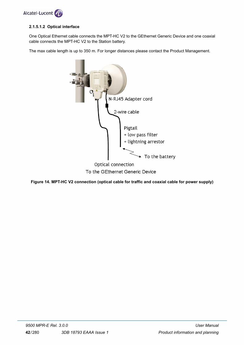
2.1.5.1.2 Optical interface
One Optical Ethernet cable connects the MPT-HC V2 to the GEthernet Generic Device and one coaxial cable connects the MPT-HC V2 to the Station battery.
The max cable length is up to 350 m. For longer distances please contact the Product Management.
Figure 14. MPT-HC V2 connection (optical cable for traffic and coaxial cable for power supply)
User Manual
Product information and planning
9500 MPR-E Rel. 3.0.0
3DB 18793 EAAA Issue 142/280

2.1.6 MPT-MC
MPT-MC is similar to MPT-HC from architecture standpoint. The only differences are:
– MPT-MC is medium capacity
– MPT-MC is natively Ethernet powered through a proprietary PFoE
– MPT-MC cannot be connected in optical -> 100m length cable limitation.
Figure 15. MPT-MC
2.1.6.1 MPT-MC connectivity
The MPT-MC is connected to a Power Injector through one electrical Ethernet cable.
The max cable length is up to 100 m.
In Figure 16. and Figure 17. are shown the connections implemented with the two available Power Injec-tors.
The Power Injector box is an indoor device to be installed in a 19”/21” rack.
The Power Injector plug-in is a unit to be installed in an MSS-8 or MSS-4.
User Manual
Product information and planning
9500 MPR-E Rel. 3.0.0
3DB 18793 EAAA Issue 1 43/280

Figure 16. MPT-MC connection through the Power Injector Box
Figure 17. MPT-MC connection through the Power Injector Plug-in installed in the SAR
User Manual
Product information and planning
9500 MPR-E Rel. 3.0.0
3DB 18793 EAAA Issue 144/280

2.1.7 Antennas
Antennas for direct mounting an MPT are available in diameters from 0.3 m to 1.8 m, depending on the frequency band.
A polarization rotator is included within the antenna collar, and direct-mounting equal or unequal loss couplers are available for single antenna protected operation.
Antenna mounts are designed for use on industry-standard 114 mm OD pipe-mounts.
An MPT can also be used with standard antennas via a remote-mount kit and flexible waveguide.
N.B. MPT can also be mounted on most of existing Melodie or AWY integrated antenna. Please con-tact for details the Alcatel-Lucent technical support.
User Manual
Product information and planning
9500 MPR-E Rel. 3.0.0
3DB 18793 EAAA Issue 1 45/280
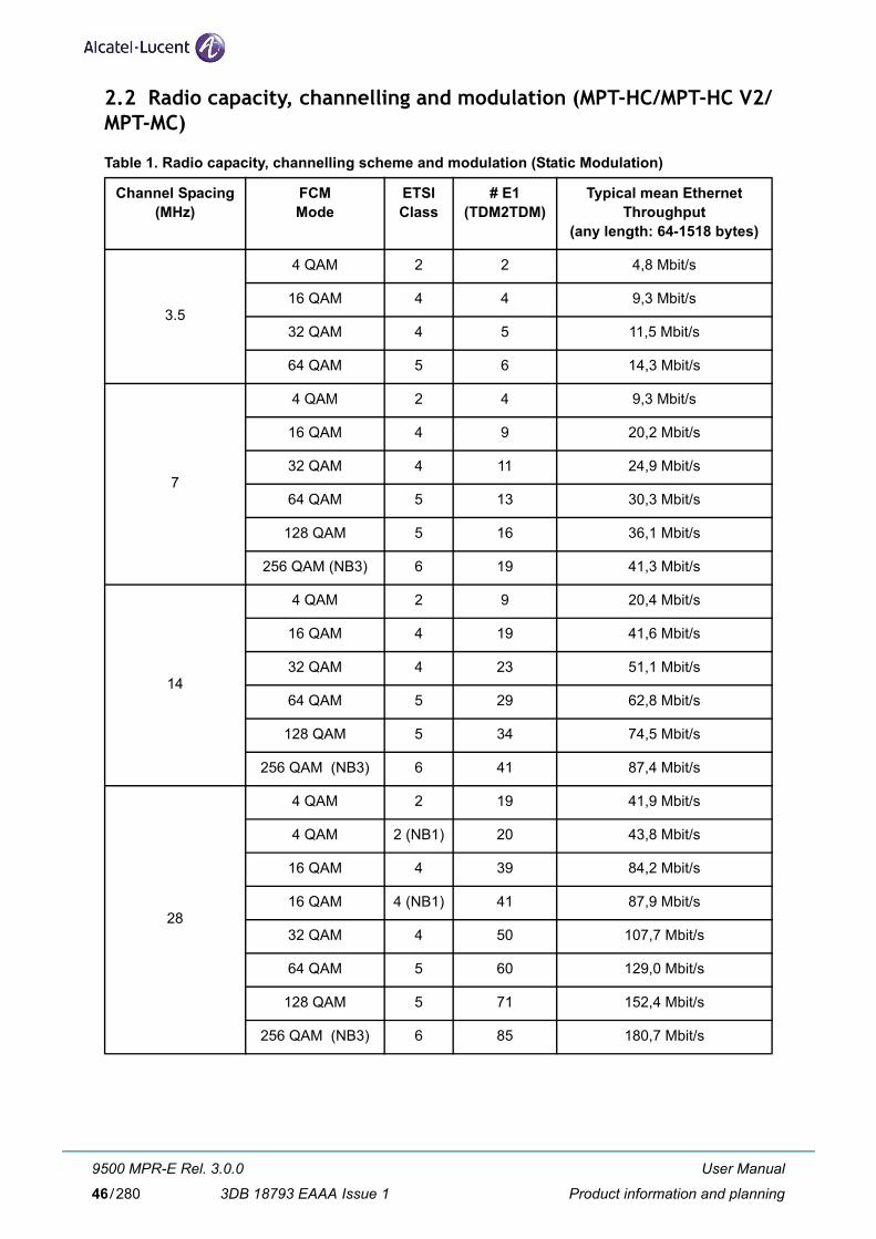
2.2 Radio capacity, channelling and modulation (MPT-HC/MPT-HC V2/MPT-MC)
Table 1. Radio capacity, channelling scheme and modulation (Static Modulation)
Channel Spacing(MHz)
FCM Mode
ETSI Class
# E1(TDM2TDM)
Typical mean Ethernet Throughput
(any length: 64-1518 bytes)
3.5
4 QAM 2 2 4,8 Mbit/s
16 QAM 4 4 9,3 Mbit/s
32 QAM 4 5 11,5 Mbit/s
64 QAM 5 6 14,3 Mbit/s
7
4 QAM 2 4 9,3 Mbit/s
16 QAM 4 9 20,2 Mbit/s
32 QAM 4 11 24,9 Mbit/s
64 QAM 5 13 30,3 Mbit/s
128 QAM 5 16 36,1 Mbit/s
256 QAM (NB3) 6 19 41,3 Mbit/s
14
4 QAM 2 9 20,4 Mbit/s
16 QAM 4 19 41,6 Mbit/s
32 QAM 4 23 51,1 Mbit/s
64 QAM 5 29 62,8 Mbit/s
128 QAM 5 34 74,5 Mbit/s
256 QAM (NB3) 6 41 87,4 Mbit/s
28
4 QAM 2 19 41,9 Mbit/s
4 QAM 2 (NB1) 20 43,8 Mbit/s
16 QAM 4 39 84,2 Mbit/s
16 QAM 4 (NB1) 41 87,9 Mbit/s
32 QAM 4 50 107,7 Mbit/s
64 QAM 5 60 129,0 Mbit/s
128 QAM 5 71 152,4 Mbit/s
256 QAM (NB3) 6 85 180,7 Mbit/s
User Manual
Product information and planning
9500 MPR-E Rel. 3.0.0
3DB 18793 EAAA Issue 146/280

N.B.1: New ETSI mask.
N.B.2: MPT-MC does not support this Channel Spacing.
N.B.3: MPT-MC does not support this FCM mode.
40 (NB2) 64 QAM 5 88 186,6 Mbit/s
128 QAM 5 104 220,6 Mbit/s
256 QAM 6 148 257,9 Mbit/s
50 (NB2) 256 QAM 6 148 314,4 Mbit/s
56 (NB2)
16 QAM 4 75 159,9 Mbit/s
16 QAM 4 (NB1) 76 161,9 Mbit/s
32 QAM 4 92 196,2 Mbit/s
64 QAM 5 119 252,6 Mbit/s
128 QAM 5 141 298,6 Mbit/s
256 QAM 6 160 339,8 Mbit/s
User Manual
Product information and planning
9500 MPR-E Rel. 3.0.0
3DB 18793 EAAA Issue 1 47/280

Table 2. Radio capacity, channelling scheme and modulation (Adaptive Modulation)
Channel Spacing(MHz)
ACM ModeReference
ETSI Class
Modulation range Typical mean Ethernet Throughput
(any length: 64-1518 bytes)
3.54 QAM 2 4 QAM to 64 QAM 4,8 Mbit/s
16 QAM 4 16 QAM to 64 QAM 9,3 Mbit/s
7
4 QAM 2 4 QAM to 256 QAM 9,3 Mbit/s
16 QAM 4 16 QAM to 256 QAM 20,2 Mbit/s
32 QAM 4 32 QAM to 256 QAM 24,9 Mbit/s
64 QAM 5 64 QAM to 256 QAM 30,3 Mbit/s
14
4 QAM 2 4 QAM to 256 QAM 20,4 Mbit/s
16 QAM 4 16 QAM to 256 QAM 41,6 Mbit/s
32 QAM 4 32 QAM to 256 QAM 51,1 Mbit/s
64 QAM 5 64 QAM to 256 QAM 62,8 Mbit/s
28
4 QAM 2 4 QAM to 256 QAM 41,9 Mbit/s
4 QAM 2 (NB2) 4 QAM to 256 QAM 43,8 Mbit/s
16 QAM 4 16 QAM to 256 QAM 84,2 Mbit/s
16 QAM 4 (NB2) 16 QAM to 256 QAM 87,9 Mbit/s
32 QAM 4 32 QAM to 256 QAM 107,7 Mbit/s
64 QAM 5 64 QAM to 256 QAM 129,0 Mbit/s
40 (NB1) 64 QAM 5 64 QAM to 128 QAM 186,6 Mbit/s
56 (NB1)
16 QAM 4 16 QAM to 256 QAM 159,9 Mbit/s
16 QAM 4 (NB2) 16 QAM to 256 QAM 161,9 Mbit/s
32 QAM 4 32 QAM to 256 QAM 196,2 Mbit/s
64 QAM 5 64 QAM to 256 QAM 252,6 Mbit/s
N.B.1: MPT-MC does not support this Channel Spacing.
N.B.2: New ETSI mask.
User Manual
Product information and planning
9500 MPR-E Rel. 3.0.0
3DB 18793 EAAA Issue 148/280

2.3 Standard Features
More radio and site scalability and flexibility for installation teams:
– Limited need for factory presetting channel frequency or bandwidth
– Supports cellular mobile networks, and microcellular network back and common carrier, private carrier and data networks, and utility haul applications.
– Outdoor Unit capacity and modulation independent
– Outdoor Unit can support either split-mount and full-outdoor architecture with the same hardware
– Adaptive packet transport that improves performance for priority services
– Output power agility
– ATPC
– Adaptive Modulation
– Electrical/Optical GE interfaces
– QoS on the Ethernet traffic
– Software-based configuration
2.4 Radio Configurations
In the current release the following radio configuration is available:
– 1+0 full outdoor
User Manual
Product information and planning
9500 MPR-E Rel. 3.0.0
3DB 18793 EAAA Issue 1 49/280

2.5 Environmental and Electrical Characteristics
– General characteristics (MPT-HC/MPT-HC V2/MPT-MC) (par. 2.5.1)
– MPT-HC/MPT-HC V2 characteristics (par. 2.5.2)
– MPT-MC characteristics (par. 2.5.3)
– Radio performances (par. 2.5.4)
– General characteristics (Power Injector) (par. 2.5.5)
– General characteristics (Power Extractor) (par. 2.5.6)
2.5.1 General characteristics (MPT-HC/MPT-HC V2/MPT-MC)
General with MPT-HC/MPT-HC V2
Operating Frequency Range 6 - 38 GHz
Max. Ethernet throughput 340 Mbps
Bandwidth up to 56 MHz
Modulation Options in FCM QPSK, 8PSK, 16 QAM, 32 QAM, 64 QAM, 128 QAM, 256 QAM
Adaptive Modulation QPSK, 8PSK, 16 QAM, 32 QAM, 64 QAM, 128 QAM, 256 QAM
General with MPT-MC
Operating Frequency Range 6 - 38 GHz
Max. Ethernet throughput 155 Mbps
Bandwidth up to 28 MHz
Modulation Options in FCM QPSK, 8PSK, 16 QAM, 32 QAM, 64 QAM, 128 QAM
Adaptive Modulation QPSK, 8PSK, 16 QAM, 32 QAM, 64 QAM, 128 QAM
Radio Path Protection Options
Non Protected, 1+0
Standards Compliance (MPT-HC/MPT-HC V2/MPT-MC)
EMC EN 301 489-1, EN 301 489-4, EN 55022 Class B
Stationary use ETS 300 019, Class 4.1
Storage ETS 300 019, Class 1.2
Transportation ETS 300 019, Class 2.3
Safety IEC 60950-1/EN 60950-1
Radio Frequency EN 302 217 Classes 2, 4 & E5
Water Ingress IEC 60529 (IPX6)
User Manual
Product information and planning
9500 MPR-E Rel. 3.0.0
3DB 18793 EAAA Issue 150/280

Environmental
Operating Temperature(Guaranteed)
-33° to +55° C
Start up temperature from low temperature
-40° C
Humidity(Guaranteed)
0 to 100%
Management
TMN In-band Extension of the DCN over the Ethernet traffic interfaces
User Manual
Product information and planning
9500 MPR-E Rel. 3.0.0
3DB 18793 EAAA Issue 1 51/280

2.5.2 MPT-HC/MPT-HC V2 characteristics
2.5.2.1 6 to 13 GHz
System
Frequency Range, GHz 5.925 - 6.425
6.425 - 7.11
7.125 - 7.9
7.725 - 8.5
10.7 - 11.7
12.75 - 13.25
T-R Spacings supported MHz 252.04 340 154, 161, 168, 196,
245
119; 126; 151.614;
208; 213,5;
266; 294; 305;
311.32
490-530 266
Antenna Interface
Waveguide Type WR137 WR137 WR112 WR113 WR75 WR62
Input voltage range -28 V to -58 V
Typical power consumption (MPT-HC) 38 W
Guaranteed power consumption (MPT-HC)
Typical power consumption (MPT-HC V2) 37 W
Guaranteed power consumption (MPT-HC V2)
Typical power consumption (MPT-HC V2 with RPS module)
Guaranteed power consumption (MPT-HC V2 with RPS module)
Typical power consumption (MPT-HC V2 with XPIC-RPS module)
Guaranteed power consumption (MPT-HC V2 with XPIC-RPS module)
L6 GHz U6 GHz 7 GHz 8 GHz 11 GHz 13 GHz
40 W
39 W
38 W
40 W
45 W
47 W
User Manual
Product information and planning
9500 MPR-E Rel. 3.0.0
3DB 18793 EAAA Issue 152/280

2.5.2.2 15 to 38 GHz
System
Frequency Range, GHz 14.4 - 15.35
17.7 - 19.7
21.2 - 23.632
24.52 - 26.483
37.0 - 39.46
T-R Spacings supported MHz 308-315-322, 420-475, 490, 644, 728
1008-1010,
1560, 340
1008- 1050-1200-1232
1008 1260
Antenna Interface
Waveguide Type WR62 WR42 WR42 WR42 WR28
Input voltage range -28 V to -58 V
Typical power consumption (MPT-HC) 38 W
Guaranteed power consumption (MPT-HC)
Typical power consumption (MPT-HC V2) 37 W
Guaranteed power consumption (MPT-HC V2)
Typical power consumption (MPT-HC V2 with RPS module)
Guaranteed power consumption (MPT-HC V2 with RPS module)
Typical power consumption (MPT-HC V2 with XPIC-RPS module)
Guaranteed power consumption (MPT-HC V2 with XPIC-RPS module)
15 GHz 18 GHz 23 GHz 26 GHz 38 GHz
40 W
39 W
38 W
40 W
45 W
47 W
User Manual
Product information and planning
9500 MPR-E Rel. 3.0.0
3DB 18793 EAAA Issue 1 53/280

2.5.3 MPT-MC characteristics
2.5.3.1 6 to 13 GHz
System
Frequency Range, GHz 5.925 - 6.425
7.125 - 7.9
7.725 - 8.5
10.7 - 11.7
12.75 - 13.25
T-R Spacings supported MHz 252.04 154-161-168-196
119-126-294-305-311-32
490-500-530
266
Antenna Interface
Waveguide Type WR137 WR112 WR113 WR75 WR62
Typical power consumption 38 W
Guaranteed power consumption
2.5.3.2 15 to 38 GHz
System
Frequency Range, GHz 14.4 - 15.35
17.7 - 19.7
21.2 - 23.632
24.52 - 26.483
37.0 - 39.46
T-R Spacings supported MHz 420- 490 1008-1010- 1560
1008- 1050-1200-1232
1008 1260
Antenna Interface
Waveguide Type WR62 WR42 WR42 WR42 WR28
Typical power consumption 38 W
Guaranteed power consumption
2.5.4 Radio performances
The radio performances are provided in the “Technical Description” document.
L6 GHz 7 GHz 8 GHz 11 GHz 13 GHz
40 W
15 GHz 18 GHz 23 GHz 26 GHz 38 GHz
40 W
User Manual
Product information and planning
9500 MPR-E Rel. 3.0.0
3DB 18793 EAAA Issue 154/280

2.5.5 General characteristics (Power Injector)
Power Injector
Input Voltage range -38.4 to -57.6 Vdc
Standards Compliance (Power Injector)
EMC EN 301 489-1, EN 301 489-4, EN 55022 Class B
Stationary use ETS 300 019 1-3, Class 3.2
Storage ETS 300 019 2-1, Class 1.2
Transportation ETS 300 019 2-2, Class 2.3
Safety EN 60950
Environmental
Operating Temperature(Guaranteed)
-40° to +65° C
Humidity(Guaranteed)
0 to 95%, non condensing
2.5.6 General characteristics (Power Extractor)
Standards Compliance (Power Extractor)
EMC EN 301 489-1, EN 301 489-4, EN 55022 Class B
Stationary use ETS 300 019 2-4, Class 4M5 sinusoidal, random and shock
Storage ETS 300 019, Class 1.3
Transportation ETS 300 019 2-2, Class 2.3
Safety EN 60950
Environmental
Operating Temperature(Guaranteed)
-33° to +55° C
Start up temperature from low temperature
-40° C
Humidity(Guaranteed)
0 to 100%
User Manual
Product information and planning
9500 MPR-E Rel. 3.0.0
3DB 18793 EAAA Issue 1 55/280

2.6 Parts Lists
2.6.1 Indoor items
Table 3. Indoor item codes
APR Name APR Code Remarks
[A] Power Injector box 3CC 50129 AAXX To be installed in a 19”/21” rack to provide the PFoE to the MPT-MC
[B] Power Injector plug-in 3CC 50128 AAXX To be installed in a SAR shelf to provide the PFoE to the MPT-MC
[C] Bracket 3DB 77008 ACXX Bracket to be used to install the Power Injector box in a 19” rack
[D] 21” Adapter kit 3CC 50065 AAAA Kit to be used with item [C] to install the Power Injector box in a 21” rack
Table 4. CD-ROM Software codes
APR name APR Code
TCO Software Suite Rel 4.3 CD-ROM 3DB75014AAAA
SWP MPR-E Rel 3.0.0 PACKET CD-ROM 3DB18819AAAA
SWP MPR-E Rel 3.0.0 HYBRID CD-ROM 3DB18818AAAA
9500 MPR Rel 3.0.0User Manual CD-ROM EN
3DB18794AAAA
2.6.2 MPT-HC optical interface option
Table 5. MPT-HC option
APR Name APR Code Remarks
SFP 1000 SX 1AB 38376 0001 Optical SFP module to be installed optionally in the MPT-HC to provide the optical Giga Ethernet interface
2.6.3 MPT-HC V2 external modules (mandatory)
Table 6. MPT-HC V2 external modules
Description APR Codes Remarks
RPS MODULE 3DB20117BAXX All frequency bands
XPIC-RPS MODULE 3DB20116BAXX All frequency bands. This module is also XPIC-ready and the XPIC connector will be used when the XPIC feature will be available.
User Manual
Product information and planning
9500 MPR-E Rel. 3.0.0
3DB 18793 EAAA Issue 156/280

2.6.4 MPT-HC with internal diplexer
Table 7. MPT-HC codes with internal diplexer
Band (GHz) Shifter (MHz) Tx sub-band APR codes Tx frequency (MHz)
L6 252 1 3DB20441ABXX 5930-6049
1P 3DB20443ABXX 6182-6302
2 3DB20442ABXX 6048-6168
2P 3DB20444ABXX 6301-6420
U6 340 1 3DB20437ABXX 6420-6600
1P 3DB20439ABXX 6760-6940
2 3DB20438ABXX 6565-6745
2P 3DB20440ABXX 6905-7085
3 3DB20464ABXX 6595-6775
3P 3DB20465ABXX 6935-7115
11 530-490 1 3DB20371ABXX 10695-10955
1P 3DB20547ABXX 11205-11485
2 3DB20546ABXX 10935-11205
2P 3DB20548ABXX 11445-11705
13 266 1 3DB20372ABXX 12750-12865
1P 3DB20420ABXX 13016-13131
2 3DB20419ABXX 12861-12980
2P 3DB20421ABXX 13127-13246
15 308-315-322 1 3DB20466ABXX 14630-14766
1P 3DB20468ABXX 14945-15081
2 3DB20467ABXX 14759-14899
2P 3DB20469ABXX 15074-15215
420-475 1 3DB20373ABXX 14500-14724
1P 3DB20423ABXX 14920-15144
420 2 3DB20422ABXX 14710-14941
2P 3DB20424ABXX 15130-15361
490 1 3DB20425ABXX 14400-14635
1P 3DB20427ABXX 14890-15125
2 3DB20426ABXX 14625-14860
2P 3DB20428ABXX 15115-15350
640-644-728 1 3DB20448ABXX 14500-14700
1P 3DB20449ABXX 15144-15348
User Manual
Product information and planning
9500 MPR-E Rel. 3.0.0
3DB 18793 EAAA Issue 1 57/280

18 1560 1 3DB20432ABXX 17700-18140
1P 3DB20433ABXX 19260-19700
340 1 3DB20549ABXX 18581-18700
1P 3DB20551ABXX 18920-19040
2 3DB20550ABXX 18701-18820
2P 3DB20552ABXX 19040-19160
1008-1010 1 3DB20374ABXX 17700-18201
1P 3DB20430ABXX 18710-19211
2 3DB20429ABXX 18180-18690
2P 3DB20431ABXX 19190-19700
23 1200-1232 1 3DB20473ABXX 21198-21819
1P 3DB20475ABXX 22400-23019
1050-1200-1232 2 3DB20474ABXX 21781-22400
2P 3DB20476ABXX 22981-23600
1008 1 3DB20375ABXX 22000-22315
1P 3DB20471ABXX 23008-23323
2 3DB20470ABXX 22300-22600
2P 3DB20472ABXX 23308-23608
25 1008 1 3DB20376ABXX 24540-24997
1P 3DB20554ABXX 25548-26005
2 3DB20553ABXX 24994-25448
2P 3DB20555ABXX 26002-26456
38 1260 1 3DB20458ABXX 37050-37620
1P 3DB20460ABXX 38310-38880
2 3DB20459ABXX 37619-38180
2P 3DB20461ABXX 38879-39440
User Manual
Product information and planning
9500 MPR-E Rel. 3.0.0
3DB 18793 EAAA Issue 158/280

2.6.5 MPT-HC V2 with internal diplexer
Table 8. MPT-HC V2 codes with internal diplexer
Band (GHz) Shifter (MHz) Tx sub-band APR codes Tx frequency (MHz)
L6 252 1 3DB20441BAXX 5930-6049
1P 3DB20443BAXX 6182-6302
2 3DB20442BAXX 6048-6168
2P 3DB20444BAXX 6301-6420
U6 340 1 3DB20437BAXX 6420-6600
1P 3DB20439BAXX 6760-6940
2 3DB20438BAXX 6565-6745
2P 3DB20440BAXX 6905-7085
3 3DB20464BAXX 6595-6775
3P 3DB20465BAXX 6935-7115
11 530-490 1 3DB20371BAXX 10695-10955
1P 3DB20547BAXX 11205-11485
2 3DB20546BAXX 10935-11205
2P 3DB20548BAXX 11445-11705
13 266 1 3DB20372BAXX 12750-12865
1P 3DB20420BAXX 13016-13131
2 3DB20419BAXX 12861-12980
2P 3DB20421BAXX 13127-13246
15 308-315-322 1 3DB20466BAXX 14630-14766
1P 3DB20468BAXX 14945-15081
2 3DB20467BAXX 14759-14899
2P 3DB20469BAXX 15074-15215
420-475 1 3DB20373BAXX 14500-14724
1P 3DB20423BAXX 14920-15144
420 2 3DB20422BAXX 14710-14941
2P 3DB20424BAXX 15130-15361
490 1 3DB20425BAXX 14400-14635
1P 3DB20427BAXX 14890-15125
2 3DB20426BAXX 14625-14860
2P 3DB20428BAXX 15115-15350
640-644-728 1 3DB20448BAXX 14500-14700
1P 3DB20449BAXX 15144-15348
User Manual
Product information and planning
9500 MPR-E Rel. 3.0.0
3DB 18793 EAAA Issue 1 59/280

N.B.1: The MPT-HC V2 is a Tx High Power version vs. MPT-HC. Take in account it when MPT-HC V2 is used as spare of MPT-HC.
18 1560 1 3DB20432BAXX 17700-18140
1P 3DB20433BAXX 19260-19700
340 1 3DB20549BAXX 18581-18700
1P 3DB20551BAXX 18920-19040
2 3DB20550BAXX 18701-18820
2P 3DB20552BAXX 19040-19160
1008-1010 1 3DB20374BAXX 17700-18201
1P 3DB20430BAXX 18710-19211
2 3DB20429BAXX 18180-18690
2P 3DB20431BAXX 19190-19700
23(NB1)
1200-1232 1 3DB20473BAXX 21198-21819
1P 3DB20475BAXX 22400-23019
1050-1200-1232 2 3DB20474BAXX 21781-22400
2P 3DB20476BAXX 22981-23600
1008 1 3DB20375BAXX 22000-22315
1P 3DB20471BAXX 23008-23323
2 3DB20470BAXX 22300-22600
2P 3DB20472BAXX 23308-23608
25 1008 1 3DB20376BAXX 24540-24997
1P 3DB20554BAXX 25548-26005
2 3DB20553BAXX 24994-25448
2P 3DB20555BAXX 26002-26456
38 1260 1 3DB20458BAXX 37050-37620
1P 3DB20460BAXX 38310-38880
2 3DB20459BAXX 37619-38180
2P 3DB20461BAXX 38879-39440
User Manual
Product information and planning
9500 MPR-E Rel. 3.0.0
3DB 18793 EAAA Issue 160/280

2.6.6 MPT-MC with internal diplexer
Table 9. MPT-MC codes with internal diplexer
Band (GHz) Shifter (MHz) Tx sub-band APR codes Tx frequency (MHz)
L6 252 1 3DB20838AAXX 5930-6049
1P 3DB20840AAXX 6182-6302
2 3DB20839AAXX 6048-6168
2P 3DB20841AAXX 6301-6420
11 490-530 1 3DB20874AAXX 10695-10955
1P 3DB20876AAXX 11205-11485
2 3DB20875AAXX 10935-11205
2P 3DB20877AAXX 11445-11705
13 266 1 3DB20818AAXX 12750-12865
1P 3DB20820AAXX 13016-13131
2 3DB20819AAXX 12861-12980
2P 3DB20821AAXX 13127-13246
15 420-475 1 3DB20822AAXX 14500-14724
1P 3DB20824AAXX 14920-15144
420 2 3DB20823AAXX 14710-14941
2P 3DB20825AAXX 15130-15361
490 1 3DB20826AAXX 14400-14635
1P 3DB20828AAXX 14890-15125
2 3DB20827AAXX 14625-14860
2P 3DB20829AAXX 15115-15350
18 1560 1 3DB20864AAXX 17700-18140
1P 3DB20865AAXX 19260-19700
1008-1010 1 3DB20860AAXX 17700-18201
1P 3DB20862AAXX 18710-19211
2 3DB20861AAXX 18180-18690
2P 3DB20863AAXX 19190-19700
User Manual
Product information and planning
9500 MPR-E Rel. 3.0.0
3DB 18793 EAAA Issue 1 61/280

23 1200-1232 1 3DB20834AAXX 21198-21819
1P 3DB20836AAXX 22400-23019
1050-1200-1232 2 3DB20835AAXX 21781-22400
2P 3DB20837AAXX 22981-23600
1008 1 3DB20830AAXX 22000-22315
1P 3DB20832AAXX 23008-23323
2 3DB20831AAXX 22300-22600
2P 3DB20833AAXX 23308-23608
25 1008 1 3DB20854AAXX 24540-24997
1P 3DB20856AAXX 25548-26005
2 3DB20855AAXX 24994-25448
2P 3DB20857AAXX 26002-26456
38 1260 1 3DB20870AAXX 37050-37620
1P 3DB20872AAXX 38310-38880
2 3DB20871AAXX 37619-38180
2P 3DB20873AAXX 38879-39440
User Manual
Product information and planning
9500 MPR-E Rel. 3.0.0
3DB 18793 EAAA Issue 162/280

2.6.7 MPT-HC/MPT-HC V2/MPT-MC with external diplexer (7/8 GHz)
The diplexer included in the available BRANCHING assemblies refers to ITU–R F.385, 386 and RF special CUSTOMERS channelling with Tx/Rx separation specified in following Table 14. and Table 19. Each diplexer is a 3-port passive device with two band–pass filters as described hereafter.
Each BRANCHING assembly has two different variants by duplex spacing, depending on the RF_Tx out-put frequency band as described on the table below:
3DB Variant Channel
3DB xxxxx AAXX 1_1p
3DB xxxxx ABXX 2_2p
The arrangement between each filters on the same branching device is described below:
WARNING: f1, f2, f3 and f4 frequencies of the branching filters refer to the extreme channel frequencies and not to the cut–off frequencies of the filters.
Table 10. 7 GHz MPT-MC codes with external diplexer
Table 11. 7 GHz MPT-HC codes with external diplexer
Band (GHz) Shifter (MHz) Tx sub-band APR codes Tx frequency (MHz)
7/8 NA Lower 3DB20858AAXX 7107 - 8370
Upper 3DB20859AAXX 7261 - 8496
Band (GHz) Shifter (MHz) Tx sub-band APR codes Tx frequency (MHz)
7/8 NA Lower 3DB20454ADXX 7107 - 8370
Upper 3DB20456ADXX 7261 - 8496
User Manual
Product information and planning
9500 MPR-E Rel. 3.0.0
3DB 18793 EAAA Issue 1 63/280

Table 12. 7 GHz MPT-HC V2 codes with external diplexer
Table 13. 7 GHz MPT-HC V2 High Power codes with external diplexer
Table 14. 7 GHz Branching assemblies (for MPT-HC and MPT-MC
Band (GHz) Shifter (MHz) Tx sub-band APR codes Tx frequency (MHz)
7/8 NA Lower 3DB20454BAXX 7107 - 8370
Upper 3DB20456BAXX 7261 - 8496
Band (GHz) Shifter (MHz) Tx sub-band APR codes Tx frequency (MHz)
7/8 NA Lower 3DB20454BBXX 7107 - 8370
Upper 3DB20456BBXX 7261 - 8496
Shifter MHz
Central Freq. MHz
Filter 1 MHz (Lower Band)
Filter 2 MHz(Upper Band) BRANCHING ASSEMBLY
Low Limit f1
High Limit f2
Low Limit f3
High Limit f4 APR codes Technical Description
154 7212,0 7107,0 7163,0 7261,0 7317,0 3DB 10060 AAXX ... CH1–1P P.SH. 154_C MHz
154 7547,0 7428,0 7512,0 7582,0 7666,0 3DB 06774 AAXX ... CH1–1P P.SH. 154_A MHz
154 7603,0 7484,0 7568,0 7638,0 7722,0 3DB 06774 ABXX ... CH2–2P P.SH. 154_A MHz
154 7561,0 7442,0 7526,0 7596,0 7680,03DB 06775 AAXX
... CH1–1P P.SH.154_B MHz
160 7561,0 7442,0 7520,0 7602,0 7680,0 ... CH1–1P P.SH.160 MHz
154 7617,0 7498,0 7582,0 7652,0 7736,03DB 06775 ABXX
... CH2–2P P.SH.154_B MHz
160 7617,0 7498,0 7576,0 7658,0 7736,0 ... CH2–2P P.SH.160 MHz
161 7240,0 7124,5 7194,5 7285,5 7355,5 3DB 06780 AAXX ... CH1–1P P.SH.161_A MHz
161 7310,0 7194,5 7264,5 7355,5 7425,5 3DB 06780 ABXX ... CH2–2P P.SH.161_A MHz
161 7365,0 7249,5 7319,5 7410,5 7480,5 3DB 06781 AAXX ... CH1–1P P.SH.161_B MHz
161 7435,0 7319,5 7389,5 7480,5 7550,5 3DB 06781 ABXX ... CH2–2P P.SH.161_B MHz
161 7390,0 7274,5 7344,5 7435,5 7505,5 3DB 06782 AAXX ... CH1–1P P.SH.161_C MHz
161 7460,0 7344,5 7414,5 7505,5 7575,5 3DB 06782 ABXX ... CH2–2P P.SH.161_C MHz
161 7540,0 7424,5 7494,5 7585,5 7655,5 3DB 06783 AAXX ... CH1–1P P.SH.161_D MHz
161 7610,0 7494,5 7564,5 7655,5 7725,5 3DB 06783 ABXX ... CH2–2P P.SH.161_D MHz
161 7665,0 7549,5 7619,5 7710,5 7780,5 3DB 06784 AAXX ... CH1–1P P.SH.161_E MHz
161 7735,0 7619,5 7689,5 7780,5 7850,5 3DB 06784 ABXX ... CH2–2P P.SH.161_E MHz
161 7690,0 7574,5 7644,5 7735,5 7805,5 3DB 06785 AAXX ... CH1–1P P.SH.161_F MHz
161 7760,0 7644,5 7714,5 7805,5 7875,5 3DB 06785 ABXX ... CH2–2P P.SH.161_F MHz
User Manual
Product information and planning
9500 MPR-E Rel. 3.0.0
3DB 18793 EAAA Issue 164/280

N.B. Shifter value choice to be done by Craft Terminal.
Table 15. 8 GHz MPT-MC codes with external diplexer
Table 16. 8 GHz MPT-HC codes with external diplexer
Table 17. 8 GHz MPT-HC V2 codes with external diplexer
Table 18. 8 GHz MPT-HC V2 High Power codes with external diplexer
168 7299,0 7187,0 7243,0 7355,0 7411,0 3DB 10059 AAXX ... CH1–1P P.SH.168_B MHZ
168 7569,0 7443,0 7527,0 7611,0 7695,0 3DB 06776 AAXX ... CH1–1P P.SH.168 MHZ
168 7625,0 7499,0 7583,0 7667,0 7751,0 3DB 06776 ABXX ... CH2–2P P.SH.168 MHZ
182 7547,0 7414,0 7498,0 7596,0 7680,0 3DB 06777 AAXX ... CH1–1P P.SH.182 MHZ
182 7603,0 7470,0 7554,0 7652,0 7736,0 3DB 06777 ABXX ... CH2–2P P.SH.182 MHZ
196 7247,0 7107,0 7191,0 7303,0 7387,0 3DB 06778 AAXX ... CH1–1P P.SH.196 MHZ
196 7303,0 7163,0 7247,0 7359,0 7443,0 3DB 06778 ABXX ... CH2–2P P.SH.196 MHZ
245 7606,5 7428,0 7540,0 7673,0 7785,0 3DB 06779 AAXX ... CH1–1P P.SH.245 MHZ
245 7718,5 7540,0 7652,0 7785,0 7897,0 3DB 06779 ABXX ... CH2–2P P.SH.245 MHZ
Band (GHz) Shifter (MHz) Tx sub-band APR codes Tx frequency (MHz)
7/8 NA Lower 3DB20858AAXX 7107 - 8370
Upper 3DB20859AAXX 7261 - 8496
Band (GHz) Shifter (MHz) Tx sub-band APR codes Tx frequency (MHz)
7/8 NA Lower 3DB20454ADXX 7107 - 8370
Upper 3DB20456ADXX 7261 - 8496
Band (GHz) Shifter (MHz) Tx sub-band APR codes Tx frequency (MHz)
7/8 NA Lower 3DB20454BAXX 7107 - 8370
Upper 3DB20456BAXX 7261 - 8496
Band (GHz) Shifter (MHz) Tx sub-band APR codes Tx frequency (MHz)
7/8 NA Lower 3DB20454BBXX 7107 - 8370
Upper 3DB20456BBXX 7261 - 8496
User Manual
Product information and planning
9500 MPR-E Rel. 3.0.0
3DB 18793 EAAA Issue 1 65/280

Table 19. 8 GHz Branching assemblies (for MPT-HC and MPT-MC)
119 8366.5 8286.0 8328.0 8405.0 8447.03DB 06789 AAXX
... CH1–1P P.SH.119 MHz
126 8366.5 8282.5 8324.5 8408.5 8450.5 ... CH1–1P P.SH.126 MHz
119 8408.5 8328.0 8370.0 8447.0 8489.03DB 06789 ABXX
... CH2–2P P.SH.119 MHz
126 8408.5 8324.5 8366.5 8450.5 8492.5 ... CH2–2P P.SH.126 MHz
151.614 8315.010 8204.217 8274.189 8355.831 8425.803 3DB 06787 AAXX ... CH1–1P P.SH.151 MHz
151.614 8384.982 8274.189 8344.161 8425.803 8495.775 3DB 06787 ABXX ... CH2–2P P.SH.151 MHz
208 8217.0 8064.0 8162.0 8272.0 8370.0 3DB 10073 AAXX ... CH1–1P P.SH.208 MHZ
208 8301.0 8148.0 8246.0 8356.0 8454.0 3DB 10073 ABXX ... CH2–2P P.SH.208 MHZ
266 8097.5 7905.0 8024.0 8171.0 8290.0 3DB 06788 AAXX ... CH1–1P P.SH.266 MHZ
266 8209.5 8017.0 8136.0 8283.0 8402.0 3DB 06788 ABXX ... CH2–2P P.SH.266 MHZ
294.440
7947.835
7749.755
7851.475 8044.195
8145.915
3DB 06786 AAXX ... CH1–1PP.SH.294/305/311 MHZ305.560 7738.635 8157.035
311.320 7732.875 8162.795
311.320 8066.435 7851.475
7970.075
8162.795 8281.395
3DB 06786 ABXX ... CH2–2PP.SH.294/305/311 MHZ294.440
8063.7407862.965
8157.4058264.515
305.560 7851.845 8275.635
213.5 8147.0 8035.0 8046.0 8248.0 8259.0 3DB 10103 AAXX ... CH1–1P P.SH. 213.5 MHZ
Shifter MHz
Central Freq. MHz
Filter 1 MHz (Lower Band)
Filter 2 MHz(Upper Band)
BRANCHING ASSEMBLY
Low Limit f1
High Limit f2
Low Limit f3
High Limit f4 APR codes Technical Description
User Manual
Product information and planning
9500 MPR-E Rel. 3.0.0
3DB 18793 EAAA Issue 166/280

2.7 Functional description
2.7.1 MPT-HC
MPT-HC (Microwave Packet Transport) is a Microwave Equipment capable to transport the Ethernet traf-fic over an RF radio channel.
The MPT-HC includes a waveguide antenna port, type-N female connector for the DC connection, a main-tenance connector (with captive protection cap) for RSSI access, 1 electrical GE interface and a ground-ing stud.
N.B. The 1 GE interface for RPS is not used.
The MPT-HC can be installed on an integrated antenna or on standard poles, wall or pedestal mount, with an appropriate fastening system.
The MPT-HC (with a solar shield) incorporates the complete RF transceiver and can be associated with an integrated or separate antenna.
The cabinet is a very compact and robust weatherproof (IP 67) container, designed to be compatible with hot and very sunny climatic zones.
The MPT-HC can be rapidly installed on standard poles with an appropriate fastening system. The pole mounting is the same from 6 to 38 GHz.
The MPT-HC is fixed by means of quick latches. This system allows to change the MPT-HC without alter-ing antenna pointing.
For 6 GHz & 7/8 GHz, the MPT-HC polarization is determined by the rotation of the MPT-HC (1+0 con-figuration).
For 11 GHz to 38 GHz, the MPT-HC polarization is determined by the rotation of the polarization rotator fitted in the antenna port of the MPT-HC (1+0 configuration).
Three mechanical solutions are adopted:
[1] with embedded diplexer for cost optimisation (11 GHz to 38 GHz), where the branching (diplexer) is internal to the MPT-HC cabinet; this type of MPT-HC is identified by one Logistical Item only;
[2] with embedded diplexer for cost optimisation and different mechanics from 11-38 GHz (6 GHz), where the branching (diplexer) is internal to the MPT-HC cabinet; this type of MPT-HC is identified by one Logistical Item only;
[3] with external diplexer: due to a vary high number of shifters the diplexer is external for the flexibility of the shifter customization (7 GHz and 8 GHz), where MPT-HC is composed by two independent units: the BRANCHING assembly (containing the diplexer) and the RF TRANSCEIVER assembly (containing the RF section); each of this type of MPT-HC is identified by two Logistical Items, one for the BRANCHING assembly and another for the RF TRANSCEIVER assembly. To read the BRANCHING assembly identification label it is necessary to separate the BRANCHING assembly from the RF TRANSCEIVER assembly.
User Manual
Product information and planning
9500 MPR-E Rel. 3.0.0
3DB 18793 EAAA Issue 1 67/280

MPT-HC is broken down to the following sections:
– MPT-CB: Common Belt section. This section is Frequency independent, and all the features relevant to this unit are common to all the MPT RF options.
– MPT-RF: Radio Frequency section that is frequency dependent.
Figure 18. MPT system
The MPT-HC interface is based on a Gb Ethernet, that can be either optical or electrical depending on the needs and the cable length. If the optical port has/have to be used (data and/or RPS port), the cor-responfing SFP plug-in must be installed by opening the Cobox.
N.B. In the current release the RPS port is not used.
Figure 19. 11-38 GHz MPT-HC housing
Figure 20. 6 GHz MPT-HC housing
User Manual
Product information and planning
9500 MPR-E Rel. 3.0.0
3DB 18793 EAAA Issue 168/280

Figure 21. 7-8 GHz MPT-HC housing
2.7.1.1 MPT-HC block diagram
Figure 22. MPT-HC block diagram
User Manual
Product information and planning
9500 MPR-E Rel. 3.0.0
3DB 18793 EAAA Issue 1 69/280

2.7.1.1.1 Common Belt section
The Common Belt section is frequency independent. It is the digital section of the MPT-HC.
The main functions are the following:
1) Interfaces the GEthernet Generic Device for traffic transport and MSS communication mes-sages in both directions, through one Gigabit Ethernet optical or electrical cable.
2) Micro-Processor for
– HW configuration and monitoring of all MPT-HC parts– Dynamic regulation process such as ATPC
3) Transport of the system reference clock (synchronisation)
4) Extract management flows from the incoming traffic to the CPU port
5) Performs traffic adaptation if needed
6) Performs Quality of Service and policing on flow to be sent over the radio link.
7) Modulation and demodulation of the resulting modem frame
Power supply interface
It is provided by a "N" 50 ohms connector, with the positive to ground.
The power supply is coming from the station battery. MPT-HC input voltage range is from -28 V to -58 V.
Lightning protection
The lightning protection is internal to the MPT-HC. No external protection must be used.
This protection applies to:
– Ethernet electrical cable
– Power supply coax cable
INCA module
The INCA module hosts the physical electrical Ethernet interface.
Tx Side
Following the flow from user Ethernet port to radio, the section performs:
– Reception of incoming Ethernet frames from the optical or electrical user interface (through INCA)
– Recovery of the clock coming from the Indoor
– Switch of the management frames from user port to internal processor
User Manual
Product information and planning
9500 MPR-E Rel. 3.0.0
3DB 18793 EAAA Issue 170/280

– Generation of MPT-HC to MPT-HC messages needed for radio link (ATPC, ACM, ...)
– Compression of the TDMoEth frames header (TDM2TDM - MEF8, TDM2ETH - MEF8)
– Management of the Quality of Service
– Fragmentation of the Ethernet frames
– Shaping of the traffic to adapt it to radio bandwidth
– Tx Modem frame building
– Tx Radio frame building (FEC, pilots, ...)
– Synchronisation depending on the selected synchronisation mode (SynchE/PCR)
– Modulation in I and Q analogue signals to be sent to the RF section.
Rx Side
Following the flow from radio to user Ethernet port, the section performs:
– Reception of the I and Q analogue signals coming from the RF section
– Demodulation of the Rx radio frame into Rx modem frame
– Deframing of the Rx modem frame
– Re-assembly of fragmented Ethernet frame
– Decompression of TDMoEth frames header
– Extraction of MPT-HC to MPT-HC messages needed for radio link (ATPC, ACM, ...)
– Management of service channels frames
– Switch of the management frames from internal processor to user port.
– Send the recovered clock to the indoor
2.7.1.1.2 RF Section
There are two architectures, the difference between these two architectures are only on Rx side:
– For the first one (used in MPT-HC band 7/8 GHz) there are only two frequency conversions between RF input frequency and base band frequency
– For the second one (used for all other MPT-HC bands) there are three frequency conversions
The block diagrams of these two architectures are shown hereafter.
User Manual
Product information and planning
9500 MPR-E Rel. 3.0.0
3DB 18793 EAAA Issue 1 71/280
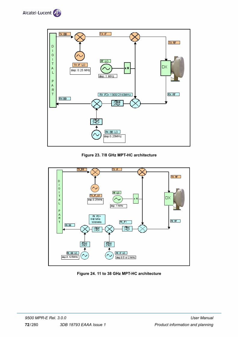
Figure 23. 7/8 GHz MPT-HC architecture
Figure 24. 11 to 38 GHz MPT-HC architecture
User Manual
Product information and planning
9500 MPR-E Rel. 3.0.0
3DB 18793 EAAA Issue 172/280

Main Functions
1. TX block:
• IF TX Quadrature modulator
• IF_Tx Synthesizer
• RF Up-Converter
• Output power management
2. Tx_Rx Common block:
• RF_LO Synthesizer
3. Rx block:
• LNA
• RF Down Converter
• First IF amplification and overload management
• First IF down conversion
• Second IF amplification and filtering (not present in 7/8 GHz)
• Quadrature demodulator
• Base band filter and AGC loop
2.7.1.2 RSSI Monitoring Point
The RSSI is available on a connector used to manually point the antenna on the field.
The higher the voltage the higher RSSI and better aligned the antenna is. To measure the RSL is used a voltmeter connected to the MPT by using a service kit cable.
Table 20. RSSI Table
Units Measurement (with MPT-HC)
Service kit cable (Vdc)
5 4.71 4.12 3.5 2.9 2.3 1.71 1.11 0.59 0.14
RSL (dBm) -10 -20 -30 -40 -50 -60 -70 -80 -90 -100
2.7.1.3 Waveguide Flange Data
Table 21. Waveguide Flange Data
Waveguide Type
L6 GHz
U6GHz
7 GHz
8 GHz
11 GHz
13 GHz
15 GHz
18 GHz
23 GHz
26 GHz
38 GHz
WR137 WR137 WR113 WR113 WR75 WR62 WR62 WR42 WR42 WR42 WR28
User Manual
Product information and planning
9500 MPR-E Rel. 3.0.0
3DB 18793 EAAA Issue 1 73/280

2.7.2 MPT-HC V2
MPT-HC V2 is similar to MPT-HC from architecture standpoint and can be used as spare part of the MPT-HC. The differences vs MPT-HC are:
– MPT-HC V2 can be natively Ethernet powered through a proprietary PFoE
– MPT-HC V2 is capable to host external modules (RPS module or XPIC_RPS module)
N.B. With release MPR3.0, the presence of one of the 2 modules is mandatory.
Two mechanical solutions are adopted:
[1] with embedded diplexer for cost optimisation (6 GHz and 11 GHz to 38 GHz), shown in Figure 25., where the branching (diplexer) is internal to the MPT-HC V2 cabinet; this type of MPT-HC V2 is iden-tified by one Logistical Item only;
[2] with external diplexer: due to an high number of shifters the diplexer is external for the flexibility of the shifter customization (7 GHz and 8 GHz), where MPT-HC V2 is composed by two independent units: the BRANCHING assembly (containing the diplexer) and the RF TRANSCEIVER assembly (containing the RF section); each of this type of MPT-HC V2 is identified by two Logistical Items, one for the BRANCHING assembly and another for the RF TRANSCEIVER assembly. To read the BRANCHING assembly identification label it is necessary to separate the BRANCHING assembly from the RF TRANSCEIVER assembly.
Figure 25. MPT-HC V2 housing (6 GHz and 11 GHz to 38 GHz)
User Manual
Product information and planning
9500 MPR-E Rel. 3.0.0
3DB 18793 EAAA Issue 174/280

2.7.3 MPT-MC
MPT-MC is similar to MPT-HC from architecture standpoint. MPT-MC has limited capacity vs MPT-HC and is natively Ethernet powered.
Two mechanical solutions are adopted:
[1] with embedded diplexer for cost optimisation (6 GHz and from 11 GHz to 38 GHz), where the branching (diplexer) is internal to the MPT-MC cabinet; this type of MPT-MC is identified by one Logistical Item only;
[2] with external diplexer: due to a vary high number of shifters the diplexer is external for the flexibility of the shifter customization (7 GHz and 8 GHz), where MPT-MC is composed by two independent units: the BRANCHING assembly (containing the diplexer) and the RF TRANSCEIVER assembly (containing the RF section); each of this type of MPT-MC is identified by two Logistical Items, one for the BRANCHING assembly and another for the RF TRANSCEIVER assembly. To read the BRANCHING assembly identification label it is necessary to separate the BRANCHING assembly from the RF TRANSCEIVER assembly.
Figure 26. 6 GHz and from 11 to 38 GHz MPT-MC housing
Figure 27. 7-8 GHz MPT-MC housing
User Manual
Product information and planning
9500 MPR-E Rel. 3.0.0
3DB 18793 EAAA Issue 1 75/280
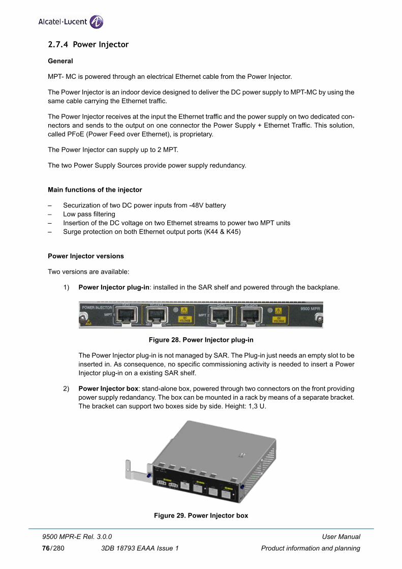
2.7.4 Power Injector
General
MPT- MC is powered through an electrical Ethernet cable from the Power Injector.
The Power Injector is an indoor device designed to deliver the DC power supply to MPT-MC by using the same cable carrying the Ethernet traffic.
The Power Injector receives at the input the Ethernet traffic and the power supply on two dedicated con-nectors and sends to the output on one connector the Power Supply + Ethernet Traffic. This solution, called PFoE (Power Feed over Ethernet), is proprietary.
The Power Injector can supply up to 2 MPT.
The two Power Supply Sources provide power supply redundancy.
Main functions of the injector
– Securization of two DC power inputs from -48V battery– Low pass filtering– Insertion of the DC voltage on two Ethernet streams to power two MPT units– Surge protection on both Ethernet output ports (K44 & K45)
Power Injector versions
Two versions are available:
1) Power Injector plug-in: installed in the SAR shelf and powered through the backplane.
Figure 28. Power Injector plug-in
The Power Injector plug-in is not managed by SAR. The Plug-in just needs an empty slot to be inserted in. As consequence, no specific commissioning activity is needed to insert a Power Injector plug-in on a existing SAR shelf.
2) Power Injector box: stand-alone box, powered through two connectors on the front providing power supply redandancy. The box can be mounted in a rack by means of a separate bracket. The bracket can support two boxes side by side. Height: 1,3 U.
Figure 29. Power Injector box
User Manual
Product information and planning
9500 MPR-E Rel. 3.0.0
3DB 18793 EAAA Issue 176/280

Connectors
– Two DC connectors in the front (for box version), or power from the backpanel (for plug-in version).– Two RJ45 for the data in (DATA)– Two RJ45 for the data + DC out (DC+DATA)
LEDs
– Two LEDs indicate the presence of DC voltage on each Ethernet output.
Figure 30. Power Injector front panel
2.7.5 Power Extractor
The Power Extractor is an Outdoor Device, to be installed close to the MPT-HC, which receives on one cable the “Power Feed over Ethernet” (Ethernet traffic and Power Supply), provided by the Power Injector, and separates the Power Supply from the Ethernet traffic to be separately sent to the MPT-HC.
Figure 31. shows the Power Extractor.
Figure 31. Power Extractor
The Power Extractor has 3 connectors:
– DC+DATA In (PFoE from the Power Injector)
– DC Out (Power Supply to MPT-HC)
– Data Out (Ethernet traffic to MPT-HC)
User Manual
Product information and planning
9500 MPR-E Rel. 3.0.0
3DB 18793 EAAA Issue 1 77/280

2.7.6 Radio Transmission Features with MPT-HC/MPT-HC V2/MPT-MC
2.7.6.1 Frequency Agility
The Frequency Agility feature gives the Operator the possibility to set via MCT the frequency of a single Transceiver within a chosen sub–band to select the RF working channel. This implies benefits for spare parts, order processing and frequency co–ordination.
2.7.6.2 Automatic Transmit Power Control (ATPC)
The Automatic Transmit Power Control (ATPC) function automatically increases or decreases the trans-mit output power upon request from the opposite terminal. The opposite terminal constantly monitors Receive Signal Level (RSL), receive signal quality, and aggregate Bit Error Rate (BER) of the receive sig-nal.
When the ATPC is Enabled the transmit output will remain at it's lowest level until a fade occurs (or a receive circuit alarm is detected). When the change in RSL is detected at the receive end, a command is sent to the transmit end to increase power in 1 dB steps to it's highest level. After the fade is over, the receive end commands the transmit power to decreases in 1 dB steps to the lowest level.
The ATPC range (high and low limits) is variable, determined by link distance, link location, and link fre-quency. When ATPC Enabled is checked, the range values are shown in parenthesis (minimum - maxi-mum) following ATPC Range.
When the ATPC is disabled the transmit output will always operate at the power value set by the MCT.
2.7.6.3 Transmitted power control: RTPC function
The capability to adjust the transmitted power in a static and fixed way (RTPC = Remote Transmit Power Control) has been introduced for those countries where, due to internal rules, the ATPC function is not accepted or for those hops in which due to the short length and interface problems, a fixed reduced transmitted power is preferred. The range of the possible attenuation depends on the frequency band involved. The setting of the transmitted power can be performed locally through MCT.
The Output power is band and modulation dependent.
2.7.6.4 Power Monitoring
The MPT-HC incorporates a detector for Tx power measurement. It is used to provide measurement of forward power as a performance parameter, and to provide a calibration input for transmitter operation over temperature and output range.
Viewed Tx power ranges always match the capabilities of the MPT-HC for a given modulation. When modulation is changed, the CT automatically adjusts/restricts Tx Power to be within valid range.
2.7.6.5 Adaptive Equalization
Adaptive equalization (AE) is employed to improve reliability of operation under dispersive fade conditions, typically encountered over long and difficult paths.
This is achieved through a multi-tap equalizer consisting of two registers, one with feed-forward taps, the other with feed-back taps. Each of these registers multiply successive delayed samples of the received signal by weighting-coefficients to remove propagation induced inter-symbol interference.
User Manual
Product information and planning
9500 MPR-E Rel. 3.0.0
3DB 18793 EAAA Issue 178/280

2.7.6.6 Link identifier
The amount of microwave links, especially in urban areas puts the problem of possible interferences during installation and turn-on phase.
The digital frame incorporates link identity coding capabilities to prevent the capture of an unwanted signal.
In case of “Link Identifier Mismatch” all the traffic is dropped.
The Link identifier management can be enabled or disabled by the management systems.
2.7.6.7 Loopbacks
To facilitate the installation/commissioning and the remote maintenance two loopbacks are available.
As the activation of a loopback affects the traffic, the presence of a loopback is indicated to the management systems as an abnormal condition.
The supported loopbacks are shown in the following figure.
Figure 32. Available loopbacks
The following loopbacks are provided by the MPT-HC or MPT-HC V2 or MPT-MC:
1) Line Side loopback: this loopback routes data from the output of the Tx Data Awareness block (after compression) to the input of the Rx data awareness (decompression). It is a Loop and Continue.When this loopback is activated the behavior is the following: – TDM2TDM and TDM2ETH flows are forwarded back to GEthernet Generic Device with
source and destination MAC address swapped. For TDM2ETH flows the loopback works only if the ECID Tx and ECID Rx are the same. In case of ECID Tx different from ECID Rx the loopback doesn't work.
– Generic Ethernet flows are dropped.
2) Radio Side loopback: remote loopback allows an over-the-air loopback test to be performed when the modem is operating in a continuous mode. The loopback connects the Receive data interface to the Transmit data interface. This loopback is a Loop and Continue. When this loopback is enabled the behavior is the following: – TDM2TDM and TDM2ETH flows are looped back with source and destination MAC
address swapped. For TDM2ETH flows the loopback works only if the ECID Tx and ECID Rx are the same. In case of ECID Tx different from ECID Rx the loopback doesn't work.
– Generic Ethernet flows are dropped.
User Manual
Product information and planning
9500 MPR-E Rel. 3.0.0
3DB 18793 EAAA Issue 1 79/280

2.7.6.8 Loopback activation
The loopback can be activated by the MCT connected to the NE. The activation command permits to define the duration of the loopback (time-out).
The time-out period starts at the activation time and expires at the end of the period spontaneously in the NE, a part for the case in which another reconfiguration of the time-out period is requested at the operator interface during the activation time. In this case, if the loopback point is still active because the activation time-out is not expired yet, the time-out period is reconfigurable and the specified time range starts again from the new updated activation date, overwriting the previous activation date and time-out values.
After the NE reset, the activation of each loopback point is lost and must be recreated again if needed, starting with a new time-out period.
2.7.7 NE IP Addresses
The NE IP address is a network IP address used for accessing the MPT through the radio and traffic Ether-net interfaces.
This address is configured statically by the operator through the management system.
The default address is 10.0.1.2.
The sub-net mask is 255.255.255.255 (/32). This mask is fixed and not configurable by the operator.
2.7.8 TMN management
The TMN In-Band interface dedicated to TMN is used to connect MPR-E NE to LAN exchanging TMN information through a VLAN mixed with the user Ethernet traffic.
This interface has a local default IP address and the operator could reconfigure this IP address as public address.
The IP address of TMN In-Band interface can be equal to the Local IP address.
If the IP address is different from the NE IP address, the TMN In-Band subnet shall be different from the NE logical subnet calculated by masking the NE IP address with the TMN In-Band subnet mask.
The default address is 192.168.100.1.
The default subnet mask is 255.255.255.0 (/24)
The default TMN In-Band VLAN ID is 4080.
User Manual
Product information and planning
9500 MPR-E Rel. 3.0.0
3DB 18793 EAAA Issue 180/280

2.7.9 Quality Of Services (QoS)
The QoS functions are properly configured in order to get the wished behavior on Ethernet flows that will be transmitted.
In the figure is shown an overview of the QoS implementation inside the MPT.
Figure 33. QoS in the MPT
The QoS feature provides eight internal queues to support different traffic priorities. The QoS function can assign the packet to one of the eight egress transmit queues.
– Queue 8 is assigned to TDM2TDM traffic (not used in the current release)
– Queue 7 is assigned to TDM2Eth traffic (not used in the current release)
– Queue 6 is assigned to TMN
Queues 1 to 5 are assigned to Ethernet traffic according to the information inside the packet as 802.1p field, DiffServ field or Ethertype.
All the MEF-8 ETH2ETH traffic flows are assigned to the Q5 egress priority queue.
QoS based on IEEE std. 802.1p
When 802.1p QoS mechanism is adopted, the reference is the standard “IEEE 802.1D-2004 Annex G User priorities and traffic classes” that defines 8 traffic types and the corresponding user priority values.
Considering that in the Radio Interface module for generic Ethernet traffic there are five egress queues the mapping 802.1p value to queue is the following:
802.1p priority Queue
111, 110 Q5 (higher priority)
101 Q4
100 Q3
011, 000 Q2
010, 001 Q1
User Manual
Product information and planning
9500 MPR-E Rel. 3.0.0
3DB 18793 EAAA Issue 1 81/280

QoS based on DiffServ
DiffServ priority Queue
111000, 110000, 101110, 101000 Q5 (higher priority)
100110, 100100, 100010, 100000 Q4
011110, 011100, 011010, 011000 Q3
010110, 010100, 010010, 010000001010, 001100, 001010, 001000, 000000
Q2
All remaining values Q1
Scheduler
HQP (High Queue Preempt) scheduler algorithm is used on Q8, Q7 and Q6.
For the other 5 queues can be selected by the MCT HQP or DWRR (Deficit Weighted Round Robin) mode.
If the DWRR has been selected, the weight to be assigned to each queue can be configured by the MCT.
By default the DWRR algorithm is used with the following weights:
Queue Weight
Q5 (higher priority) 16
Q4 8
Q3 4
Q2 2
Q1 1
2.7.10 Synchronization
The MPT can be configured to be synchronized in two different modes:
– SynchE (Synchronous Ethernet). With this mode for the electrical interface the selection among Autonegotiation/Master/Slave must be performed.
– PCR (Proprietary Clock Recovery): the time stamp inside the Ethernet frame is used. With this mode the Source MAC address and the Destination MAC address must be assigned.
The MPT can be also configured to synchronize itself and to discard any external synchronization.
Note: SSM are transparently forwarded in most of the configurations (please refer to Customer Release Note 9500MPR-E Microwave Packet Radio Release 3.0 3DB18755AAAAFMZZA for the exceptions).
User Manual
Product information and planning
9500 MPR-E Rel. 3.0.0
3DB 18793 EAAA Issue 182/280

3 NE Management by software application
3.1 WebEML start
This chapter explains all the screens of the WebEML, which is started by a double click on the WebEML icon of the PC desktop.
The WebEML must be connected to the GEthernet Generic Device as explained in Chapter 5.
Refer to paragraph 4.3 - “Software local copy” to get all the information to copy the WebEML from the soft-ware package CD ROM and to connect the PC to the GEthernet Generic Device to access the MPT-HC/MPT-HC V2/MPT-MC.
N.B. The PC shall be in the same sub-network as the default IP address of the TMN In-band (first connection), or refer to the end of the document to make it work.
1) To start the WebEML double click on the relevant icon on the PC desktop.
2) NETO opens. Insert the IP address of the NE (default: 192.168.100.1) and click OK.
User Manual
NE Management by software application
9500 MPR-E Rel. 3.0.0
3DB 18793 EAAA Issue 1 83/280

3) When the NE is supervised, click Show.
4) The Main view opens.
Figure 34. shows the Main View of an MPT-HC.
The same screen (and same menus) will appear with a connection to an MPT-MC. The only difference is the naming.
Tool bar
AlarmSynthesis
Navigator
Generalinformation
Domain Alarm Synthesis Tab-panels
IP address of the connected NE
Connection status
Figure 34. Main view: System Overview
User Manual
NE Management by software application
9500 MPR-E Rel. 3.0.0
3DB 18793 EAAA Issue 184/280

3.2 Tool bar
The Tool bar has three buttons:
– Exit: to quit the application
– Connect to NE: to establish the connection to the NE
– Disconnect: to disconnect the NE
3.3 Alarm Synthesis
The CT provides an alarm functionality that informs the operator on the severity of the different alarms in the NE as well as on the number of current alarms. There are five different alarm severity levels. In the CT these different levels are associated with colors.
– Red: Critical alarm (CRI)
– Orange: Major alarm (MAJ)
– Yellow: Minor alarm (MIN)
– Cyan: Warning alarm (WAR)
– Blue: Indeterminate (IND)
The meaning of the icons in the Alarm Synthesis is:
[1] CRI - Critical alarmSynthesis of alarms that needs immediate troubleshooting (typical: NE isolation).
[2] MAJ - Major (Urgent) alarmSynthesis of alarms that needs immediate troubleshooting.
[3] MIN - Minor (Not Urgent) alarmSynthesis of alarms for which a deferred intervent can be decided.
[4] WAR - Warning alarmSynthesis of alarms due to failure of other NE in the network.
[5] IND - Indeterminate alarmSynthesis of alarms not associated with the previous severities. Not operative.
Each alarm severity is represented by an alarm icon situated in the top left hand corner of the view. These alarm icons are constantly represented on the different Equipment views so that the operator is always aware of the alarms occurring in the system.
Furthermore the number in the alarm icon gives the number of active alarms with that specific severity.
User Manual
NE Management by software application
9500 MPR-E Rel. 3.0.0
3DB 18793 EAAA Issue 1 85/280

3.4 Domain Alarm Synthesis Area
This area contains the icons representing the alarms per domain. Each icon indicates the number of alarm occurrences for each domain.
The meaning of the icons in the Domain alarm synthesis area is:
[1] COM – Communication alarmSynthesis of alarms of the Communication domain.
[2] EQP – Equipment alarmSynthesis of alarms of the Equipment domain.
3.5 General Information on the Management State
The different management states concerning the NE are shown in two tab-panels:
– Radio Synthesis
– Network Supervision
The Radio Synthesis gives information on the:
– Abnormal Condition state: indicates whether some abnormal conditions have been recognized.
The Network Supervision gives information on the:
– Local Access state: indicates whether the NE is managed by a craft terminal or by the OS
– OS Supervision state: indicates whether or not the communication with the OS is established.
User Manual
NE Management by software application
9500 MPR-E Rel. 3.0.0
3DB 18793 EAAA Issue 186/280

3.6 Navigator area
The Navigator menu depends on the selected function in the upper tab-panels.
Four tab-panels are available:
[1] Commissioning (par. 3.6.1 on page 88)
• Inventory
• Software Download
• Configuration (par. 3.6.1.3 on page 92)
– Date/Time– Site Information– Protection– Synchronization– Radio– Advanced Radio– Ethernet Traffic QoS– Networking
• Backup / Restore
• Monitoring
[2] Performance Monitoring (par. 3.6.2 on page 108)
• Performance History File Upload
• Normalized
• Adaptive Modulation
• Ethernet
• Monitoring
[3] Troubleshooting (par. 3.6.3 on page 119)
• Inventory
• Troubleshooting
• Monitoring
[4] Maintenance (par. 3.6.4 on page 122)
• Inventory
• Software Download
• Configuration > Radio
• Monitoring
The System Overview tab-panel (Figure 34) is the Welcome screen of the WebEML. It is a read-only screen, which shows all the configuration parameters of the MPT.
User Manual
NE Management by software application
9500 MPR-E Rel. 3.0.0
3DB 18793 EAAA Issue 1 87/280

3.6.1 Commissioning
This menu has four sub-menus:
– Inventory
– Software Download
– Configuration
– Monitoring
3.6.1.1 Inventory
This menu provides all the inventory data of the MPT.
Figure 35. Inventory
User Manual
NE Management by software application
9500 MPR-E Rel. 3.0.0
3DB 18793 EAAA Issue 188/280

3.6.1.2 Software Download
This menu must be used to download a new software version on the NE (Software Package Versionstab-panel) or to get a summary of the specific software versions on the programmable different compo-nents on the Active bank (Active Software Package Summary tab-panel) or on the Stand-by bank (Stand-by Software Package Summary tab-panel).
3.6.1.2.1 Software Package Versions tab-panel
Figure 36. Software Download: Software Package versions
Warning: On the PC containing the Software Package must be installed an FTP Server.
To download a new software version fill the FTP Server Parameters field (as shown in Figure 37):
– Server Address: enter the IP address of the Server
– Username: enter the username assigned to the FTP Server
– Password: enter the password assigned to the FTP Server
– Port: 21
then click on the Check button.
– Select in the Software Package field the file descriptor (previously copied on the PC).Note: The path where to find the file descriptor, after the SWP local copy, is //ECT/SWDW/R95MPRE/1_1_0/R95SA.DSC
– Put a check mark on the Forced check box to download the complete file without any comparison between the file already present in the stand-by bank and the new file to be downloaded.
– Press the Start Download button.
– At the end press the Activate button of the Stand-by Software Package.
User Manual
NE Management by software application
9500 MPR-E Rel. 3.0.0
3DB 18793 EAAA Issue 1 89/280

Warning: After the activation of the Standby bank, the connection between WebEML and MPT is lost. The WebEML must be re-launched.
Figure 37. Software download
3.6.1.2.2 Active Software Package Summary tab-panel
This tab-panel shows the versions of the programmable different components of the active bank.
Figure 38. Software Download: Active Software Package summary
User Manual
NE Management by software application
9500 MPR-E Rel. 3.0.0
3DB 18793 EAAA Issue 190/280

3.6.1.2.3 Stand-by Software Package Summary tab-panel
This tab-panel shows the versions of the programmable different components of the stand-by bank.
Figure 39. Software Download: Stand-by Software Package summary
User Manual
NE Management by software application
9500 MPR-E Rel. 3.0.0
3DB 18793 EAAA Issue 1 91/280

3.6.1.3 Configuration
3.6.1.3.1 Date/Time
The NE Date/Time screen displays the current NE time and the current computer time.
To re-align the NE time to the computer time, click on the Synchronize NE with Computer button and click on the Refresh button.
If an SNTP Server has to be used to distribute the time, the SNTP protocol must be enabled by a check mark in the SNTP Enabled box and the IP address of the Server must be inserted in the relevant field. The IP address of the Spare Server, if available, must be inserted in the relevant field.
Figure 40. Date/Time Configuration
User Manual
NE Management by software application
9500 MPR-E Rel. 3.0.0
3DB 18793 EAAA Issue 192/280

3.6.1.3.2 Site Information
This menu has to be used to insert the optional information to identify the site (Site Name and Site Loca-tion).
Figure 41. Site Information
3.6.1.3.3 Protection
Select the 1+0 protection scheme.
Figure 42. Protection Configuration
User Manual
NE Management by software application
9500 MPR-E Rel. 3.0.0
3DB 18793 EAAA Issue 1 93/280

3.6.1.3.4 Synchronization
This menu allows to synchronize the MPT.
Two ways for external synchronization or internal synchronization mode can be selected.
– External synchronization:
• PCR (Figure 43.)
• SynchE (Figure 44.)
– Internal synchronization (Figure 45.)
Figure 43. Synchronization (PCR)
Figure 44. Synchronization (SynchE)
User Manual
NE Management by software application
9500 MPR-E Rel. 3.0.0
3DB 18793 EAAA Issue 194/280

Figure 45. Synchronization (Internal)
– If PCR has been selected, the Source Mac Address and the Destination Mac Address have to be entered.
– If SynchE has been selected, for the electrical interface the selection among Automatic/Master/Slave must be done.
3.6.1.3.5 Radio
1) Telecommunication standard
Select the ETSI or ANSI market.
2) Modulation
The operation mode can be with Fixed Modulation (FCM) or with the Adaptive Modulation (ACM).
a) Operation with the Fixed Modulation (FCM) (Figure 46 and Figure 47)
• Select in the Coding Modulation Type field “Fixed (FCM)”.
• Select in the Channel Spacing field the suitable channel spacing to be used (up to 56 MHz for MPT-HC and up to 28 MHz for MPT-MC).
• Select the Modem Profile Option: Current mask standard profile or New mask stan-dard profile
• Select in the Reference Modulation field the suitable Modulation scheme (up to 256 QAM for MPT-HC and up to 128 QAM for MPT-MC).
• According to the selected Channel Spacing and to the Modulation the relevant capacity in the Capacity field will appear.
User Manual
NE Management by software application
9500 MPR-E Rel. 3.0.0
3DB 18793 EAAA Issue 1 95/280

b) Operation with the Adaptive Modulation (ACM) (Figure 48)
The main idea behind Adaptive Modulation in Point to Point system is to adjust adaptively the modulation as well as a range of other system parameters based on the near-instan-taneous channel quality information perceived by the receiver, which is feed back to the transmitter with the aid of a feedback channel.
The switching between the modulation schemes is hitless and maintains the same RF channel bandwidth.
To configure the Adaptive Modulation:
• Select in the Coding Modulation Type field “Adaptive (ACM)”.• Select in the Channel Spacing field the suitable channel spacing. • Select in the Modem Profile Option field the spectral efficiency class to be set as
reference: Current ETSI mask or New ETSI mask. • Select in the Reference Modulation field the reference modulation, which corre-
sponds to the lowest modulation scheme.• Choose in the Allowed Modulation field all the modulation schemes to be used with
the Adaptive Modulation. The modulation schemes (from the lowest to the highest scheme) must be contiguous.
3) Frequency
The system can operate with different types of ODU according to the RF band and to the chan-nel arrangement. There are ODUs which can manage only one shifter or several predefined shifters.
In the Shifter field select the suitable shifter.
In the Tx frequency field insert the suitable Tx frequency (the Rx frequency is automatically calculated by using the inserted Tx frequency and the shifter).
In the Rx frequency field will appear the calculated Rx frequency, but, by putting a check mark in the Allow Rx Frequency Tuning check box this frequency can be changed in +5 MHz range to implement the “Exotic” shifter configuration, if required.
4) Tx Mute
To mute the transmitter put a check mark in the Mute check box.
5) Transmit Power Control Mode
Select the Mode: RTPC or ATPC.
6) RTPC settings
– Tx power without Adaptive Modulation
If the ATPC is disabled the Tx Power field is available. For the Tx Power range refer to the indication in the screen.
In this field write the new value within the allowed transmitted power range.
User Manual
NE Management by software application
9500 MPR-E Rel. 3.0.0
3DB 18793 EAAA Issue 196/280

– Tx Power with Adaptive Modulation
The operator can modify only the Tx power relevant to the lowest modulation scheme. In this field the operator has to enter the constant power, which will be used with the lowest modulation.
The same power value will be used by the other modulation schemes.
7) ATPC settings
The ATPC cannot be set with ACM (only with FCM).
– ATPC Remote RSL Threshold
The value of the low power threshold can be changed by writing the new value in the field. When the Rx power is equal to this power the ATPC algorithm starts to operate.
– Min ATPC Tx power and Max ATPC Tx power
The Min Tx power and Max Tx power, regarding the Tx Range in the ATPC management, can be written in the relevant field.
Figure 46. Radio Configuration: FCM - RTPC
Note
User Manual
NE Management by software application
9500 MPR-E Rel. 3.0.0
3DB 18793 EAAA Issue 1 97/280

Figure 47. Radio Configuration: FCM - ATPC
Figure 48. Radio Configuration: ACM - RTPC
User Manual
NE Management by software application
9500 MPR-E Rel. 3.0.0
3DB 18793 EAAA Issue 198/280

3.6.1.3.6 Advanced Radio
Figure 49. Advanced Radio Configuration
This menu allows the operator to define the expected and sent identifier values of parameters related to the link management and, if necessary, modify them.
If the link identifier is Enabled the following fields can be written:
– Tx Radio Link Identifier: this field is the link identifier inserted on the transmitting NE (1 to 255)
– Expected Rx Radio Link Identifier: this field is the link identifier expected at the receiving NE (0 to 255).
User Manual
NE Management by software application
9500 MPR-E Rel. 3.0.0
3DB 18793 EAAA Issue 1 99/280

3.6.1.3.7 Ethernet Traffic QoS
This menu allows to:
[1] Select the QoS Classification
[2] Set the Classification according to the EtherType
[3] Set the Scheduling Algorithms
Note: For the QoS the first match for the classification is done according to 802.1p/DiffServ (point [1]). If there is no match, the classification is done according to the EtherType (point [2]). If there is no match, the Ethernet frame is sent to the lower priority queue.
Figure 50. Ethernet Traffic QoS
[1] QoS classification
Two methods can be selected:
• IEEE 802.1p (refer to Figure 51.)
• DiffServ (refer to Figure 52.)
User Manual
NE Management by software application
9500 MPR-E Rel. 3.0.0
3DB 18793 EAAA Issue 1100/280

IEEE 802.1p
Figure 51. IEEE 802.1p
By putting a check mark in the relevant check box each priority (0 to 7) can be assigned to a specific egress queue (queue 1 to queue 5).
N.B. Queue 5 is the highest priority queue, queue 1 is the lowest priority queue.
By pressing Default the default classification will be restored.
DiffServ
Figure 52. DiffServ
User Manual
NE Management by software application
9500 MPR-E Rel. 3.0.0
3DB 18793 EAAA Issue 1 101/280

A specific range of DiffServ Code Points can be assigned to a specific egress queue (queue 1 to queue 5).
N.B. Queue 5 is the highest priority queue, queue 1 is the lowest priority queue.
By pressing Default the default classification will be restored.
By pressing Add a new range can be assigned to a specific queue.
[2] EtherType classification
Press Add (or Add Last) to assign a specific egress queue (queue 1 to queue 5) to a specific Ether-Type.
N.B. Queue 5 is the highest priority queue, queue 1 is the lowest priority queue.
Figure 53. EtherType classification
User Manual
NE Management by software application
9500 MPR-E Rel. 3.0.0
3DB 18793 EAAA Issue 1102/280

[3] Scheduling Algorithms
Figure 54. Scheduling Algorithms
This menu allows to change the scheduler operation.
N.B. The scheduling mode refers only to Queue 1 to Queue 5, because for Queue 6 to Queue 8 the scheduling mode is fixed to HQP.
The scheduling mode can be DWRR or HQP.
If the DWRR has been selected the DWRR weight can be assigned to a specific egress queue (queue 1 to queue 5).
N.B. Queue 5 is the highest priority queue, queue 1 is the lowest priority queue.
By pressing Defaults the default algorithm will be restored.
N.B. The HQP mode can be associated to some queues and at the same time the DWRR mode can be associated to other queues. DWRR cannot be assigned to higher priority queues than those configured in HQP
User Manual
NE Management by software application
9500 MPR-E Rel. 3.0.0
3DB 18793 EAAA Issue 1 103/280

3.6.1.3.8 Networking
This menu must be used to assign (or to show) the networking configuration of the NE.
This menu has three sub-menus:
– Network Interfaces
– Static Routing
– Trusted SNMP Managers
3.6.1.3.8.1 Network Interfaces
– TMN RF Access field
Put a check box in this field to get access to the NE in the remote radio station.
– NE IP Parameters field
This IP address is the local IP address. The default IP address is: 10.0.1.2. The subnet mask is fixed to 255.255.255.255(/32).
– TMN In-band IP Parameters
Enter the IP Address with the relevant submask for the TMN In-band management. Default IP: 192.168.100.1. Default sub-net mask: 255.255.255.0(/24).In VLAN ID field enter the VLAN ID used for the In-band management (default: 4080).
Note 1: The change of these parameters will lose the connection with the MPT.
Note 2: Depending on the parameters changes and the type of generic device, it may be necessary to change the parameters of the PC/device
Figure 55. Network Interfaces
User Manual
NE Management by software application
9500 MPR-E Rel. 3.0.0
3DB 18793 EAAA Issue 1104/280

3.6.1.3.8.2 Static Routing
The Static Routing menu allows to configure the parameters for IP Static Routing Configuration.
– Route Type: possible selection is Network, Host, Default.
– Destination to address to a range of IP addresses with relevant subnet mask.
– Next Hop: the User can select Point to Point Link (to address the link on the radio side) or Gateway IP to define the address of a gateway reachable on the TMN In-band interface.
Figure 56. Static Routing
The Add button inserts above a new Static Routing Table row.
The Add Last inserts below a new Static Routing Table row.
The Delete button deletes the selected Static Routing Table row.
User Manual
NE Management by software application
9500 MPR-E Rel. 3.0.0
3DB 18793 EAAA Issue 1 105/280

3.6.1.3.8.3 Trusted SNMP Managers
A Trusted manager is an SNMP manager to which the NE automatically sends the TRAPS generated inside the NE.
Figure 57. Trusted SNMP Managers
To activate a Trusted Manager insert the IP Address of the SNMP manager, the UDP port and the Man-ager Type (Network Manager Layer or Equipment Manager Layer), then click on Register.
In Figure 58. one Manager has been created.
Figure 58. Manager registration
To delete a Manager select the Manager from the list and press Unregister.
User Manual
NE Management by software application
9500 MPR-E Rel. 3.0.0
3DB 18793 EAAA Issue 1106/280

3.6.1.4 Backup / Restore
This menu allows to make a backup (save the NE configuration to the PC) and to make a restore (down-load a configuration, from a previously done backup, to the NE). The backup and restore is done through FTP.
Figure 59. Backup / Restore
Fill the FTP Server Parameters field.
Click Browse to select the directory and the name of the file.
Press Backup or Restore according to the operation to be done.
3.6.1.5 Monitoring
For this menu refer to paragraph 3.6.5.
User Manual
NE Management by software application
9500 MPR-E Rel. 3.0.0
3DB 18793 EAAA Issue 1 107/280

3.6.2 Performance Monitoring
This menu has five sub-menus:
– Performance History File Upload
– Normalized
– Adaptive Modulation
– Ethernet
– Monitoring
3.6.2.1 Performance History File Upload
This menu allows to export in a .csv file the data regarding the performance counters. This operation is done through an FTP session.
– Fill the FTP Server Parameters area with the FTP Server parameters.
– Select in the Performance Family field the type of counters to be exported: Normalized Perfor-mance Counters (refer to par. 3.6.2.2) / Adaptive Modulation Counters (refer to par. 3.6.2.3) / MPT QoS Ingress Counters (refer to par. 3.6.2.4.1) / Traffic Port Counters (refer to par. 3.6.2.4.2).
Note: The counters to be exported must be stopped (refer to the relevant paragraphs).
– Select the History Period in second (default: 5s) and click Apply.
– Click on Browse to choose the destination directory and to assign the name of the file.
– Click on Upload History to export the file.
User Manual
NE Management by software application
9500 MPR-E Rel. 3.0.0
3DB 18793 EAAA Issue 1108/280

Figure 60. Performance History File Upload
3.6.2.2 Normalized
3.6.2.2.1 Counter Thresholds
In the Counter Threshold screen the Low Threshold and High Threshold can be changed for each G.826 parameter (BBE, ES, SES). The high threshold will cause the activation of the alarm "Threshold exceeded" during the Performance Monitoring period and the low threshold will cause the deactivation of the same alarm.
N.B. For the 24 hour report only the High Threshold can be changed.
Press Apply to send to the equipment the new parameters.
Press Default to restore the default parameters.
Figure 61. Counter Thresholds
User Manual
NE Management by software application
9500 MPR-E Rel. 3.0.0
3DB 18793 EAAA Issue 1 109/280

3.6.2.2.2 15Min Counter
The upper part of the screen will show the values of the current 15 min period, the lower part will show the last elapsed 15 min period.
Press the Activate button (1) to activate the 15 min normalized NE counter computation.
Press the Start icon (2) to start the monitoring of the current 15 min period and set the refresh period (if the NE counter computation is activated).
Press the Reset button to reset the NE counter computation (if the NE counter computation is activated)
Figure 62. 15Min Counter activation
Figure 63. 15Min Counter
User Manual
NE Management by software application
9500 MPR-E Rel. 3.0.0
3DB 18793 EAAA Issue 1110/280

When a 15 minute period is over, the period Data is automatically reported and shown on the lower part of the screen.
Figure 64. 15Min Counter history
Press the Stop icon (1) to stop the current 15 min counter monitoring.Press the Deactivate button (2) to deactivate the 15 min normalized NE counter computation (if the counter monitoring is stopped).
Figure 65. 15Min Counter deactivation
3.6.2.2.3 24H Counter
The 24H Counter is identical to the 15Min Counter, but the period is 24 hours and not 15 minutes.
User Manual
NE Management by software application
9500 MPR-E Rel. 3.0.0
3DB 18793 EAAA Issue 1 111/280

3.6.2.3 Adaptive Modulation
The Adaptive Modulation Counter screen will show the total seconds during which each modulation scheme has been used.
3.6.2.3.1 15Min Counter
The upper part of the screen will show the values of the current 15 min period, the lower part will show the last elapsed 15 min period.
Press the Activate button (1) to activate the 15 min normalized NE counter computation.
Press the Start icon (2) to start the monitoring of the current 15 min period and set the refresh period (if the NE counter computation is activated).
Press the Reset button to reset the NE counter computation (if the NE counter computation is activated).
Figure 66. Adaptive Modulation counter activation
User Manual
NE Management by software application
9500 MPR-E Rel. 3.0.0
3DB 18793 EAAA Issue 1112/280

Figure 67. 15Min Counter
When a 15 minute period is over, the period Data is automatically reported and shown on the lower part of the screen.
Figure 68. 15Min Counter history
Press the Stop icon (1) to stop the current 15 min counter monitoring.
Press the Deactivate button (2) to deactivate the 15 min normalized NE counter computation (if the counter monitoring is stopped).
User Manual
NE Management by software application
9500 MPR-E Rel. 3.0.0
3DB 18793 EAAA Issue 1 113/280

Figure 69. 15Min Counter deactivation
3.6.2.3.2 24H Counter
The 24H Counter is identical to the 15Min Counter, but the period is 24 hours and not 15 minutes.
User Manual
NE Management by software application
9500 MPR-E Rel. 3.0.0
3DB 18793 EAAA Issue 1114/280

3.6.2.4 Ethernet
3.6.2.4.1 MPT QoS Ingress Counters
MPT QoS Ingress counters computation is always activated.
The upper part of the screen will show a graphical evolution of the counters.
The lower part will show a table reporting the counter values when the monitoring is activated. Each time the counters are refreshed, an entry will be added in the table.
Press the Start icon to start the monitoring of the MPT QoS Ingress counters and set the refresh period (default : 5s ).
Press the Stop icon to stop the MPT QoS Ingress counters monitoring.
Press the Reset button to reset the NE counter computation.
Figure 70. Ethernet: Qos Counters
The QoS counters are:
– Transmitted Frames
– Discarded Frames
– Transmitted Bytes
The counters are shown in the following formats:
– bar
– graphical
– tabular
User Manual
NE Management by software application
9500 MPR-E Rel. 3.0.0
3DB 18793 EAAA Issue 1 115/280

and can be displayed for a single queue (Queue # tab-panel) or for all the queues (Aggregate tab-panel).
The default span of the graphical format is 24 hours, but is can be changed.
An example of the QoS Counters screen is given in Figure 71.
Figure 71. Qos Counters example for Queue 1
3.6.2.4.2 Traffic Port Counters
MPT Traffic Port counters computation is always activated.
The upper part of the screen will show a graphical evolution of the counters.
The lower part will show a table reporting the counter values when the monitoring is activated. Each time the counters are refreshed, an entry will be added in the table.
Press the Start icon to start the monitoring of the MPT QoS Ingress counters and set the refresh period (default : 5s ).
Press the Stop icon to stop the MPT QoS Ingress counters monitoring.
Press the Reset button to reset the NE counter computation.
User Manual
NE Management by software application
9500 MPR-E Rel. 3.0.0
3DB 18793 EAAA Issue 1116/280

Figure 72. Ethernet: Traffic Port Counters
The Traffic Port Counters are:
– Number of Bytes
– Number of Frames
– Discarded Frames
– Errored Frames
– Unicast Frames
– Multicast Frames
– Broadcast Frames
The counters are shown in the following formats:
– bar
– graphical
– tabular
An example of the Traffic Port Counters screen is given in Figure 73.
User Manual
NE Management by software application
9500 MPR-E Rel. 3.0.0
3DB 18793 EAAA Issue 1 117/280

Figure 73. Traffic Port Counters example
3.6.2.5 Monitoring
For the Alarms sub-menu refer to paragraph 3.6.5.1.
User Manual
NE Management by software application
9500 MPR-E Rel. 3.0.0
3DB 18793 EAAA Issue 1118/280

3.6.3 Troubleshooting
This menu has three sub-menus:
– Inventory
– Troubleshooting
– Monitoring
3.6.3.1 Inventory
This menu provides all the inventory data of the MPT.
Figure 74. Inventory
3.6.3.2 Troubleshooting
This menu allows:
[1] to activate the available loopbacks on the MPT;
[2] to manually manage the ACM;
[3] to restart the MPT;
[4] to manually manage the ATPC (only available in ANSI market).
[1] Two loopbacks are available:
• Line Side (the signal is send back to the Indoor equipment)
• Radio Side (the signal is send back to the remote station)
To activate a loopback select the loopback and press Activate.
User Manual
NE Management by software application
9500 MPR-E Rel. 3.0.0
3DB 18793 EAAA Issue 1 119/280

A timout can be associated to the loopback. Enter the suitable timeout (max: 4 days) and click on Apply.
Figure 75. Loopback activation
To deactivate a loopback press Deactivate.
[2] To lock the ACM engine put a check mark in the Lock ACM engine box and select the modulation scheme to be used.
Figure 76. ACM Manual Management
User Manual
NE Management by software application
9500 MPR-E Rel. 3.0.0
3DB 18793 EAAA Issue 1120/280

[3] To restart the MPT press the Restart NE button.
[4] To lock the ATPC to the min or max value put a check mark in the Lock ATPC check box.
Figure 77. ATPC Manual Management (ANSI market only)
3.6.3.3 Monitoring
For this menu refer to paragraph 3.6.5.
User Manual
NE Management by software application
9500 MPR-E Rel. 3.0.0
3DB 18793 EAAA Issue 1 121/280

3.6.4 Maintenance
The Maintenance menu has 5 sub-menus:
– Inventory (refer to paragraph 3.6.1.1)
– Backup / Restore (refer to paragraph 3.6.1.4)
– Software Download (refer to paragraph 3.6.1.2)
– Configuration > Radio (refer to paragraph 3.6.1.3.5)
– Monitoring (refer to paragraph 3.6.5)
Figure 78. Maintenance
User Manual
NE Management by software application
9500 MPR-E Rel. 3.0.0
3DB 18793 EAAA Issue 1122/280

3.6.5 Monitoring
This menu has four sub-menus:
– Alarms
– Power measurements
– Modem measurements
– Events (only in the Troubleshooting menu)
3.6.5.1 Alarms
The Alarms menu allows to display and store the alarms of the NE.
Two global lists of alarms are displayed:
– CURRENT ALARMS shows all the equipment alarms currently present,
– ALARM LOG shows all the equipment alarms currently present and the history of the alarms (i.e. cleared alarms).
When an alarm is no longer active it disappears from the Current Alarm list and it is displayed in the Alarm log list as a cleared alarm
The alarms have a different color according to their severity and their state.
– Red: CRITICAL alarm
– Orange: MAJOR alarm
– Yellow: MINOR alarm
– Cyan: WARNING alarm
– Blue: INDETERMINATE alarm (Note that the equipment has no alarm having such severity)
– Green: CLEARED alarm (alarm no longer active).
Within the tab-panel, each alarm is provided with the information below.
– Time Stamp: date and time of the alarm. The format of date and time is yyyy/mm/dd hh:mm:ss.
– Probable Cause: name of the probable cause of the alarm.
– Type: alarm class (COMMUNICATION – alarm not created inside the equipment, but generated by a connected equipment or due to transmission/propagation problems; EQUIPMENT: inside alarm of the equipment).
– Object: object of the equipment where the alarm occurred.
– Severity: alarm severity.
– Additional Text: this is an additional text regarding the alarm.
Note
User Manual
NE Management by software application
9500 MPR-E Rel. 3.0.0
3DB 18793 EAAA Issue 1 123/280

Figure 79. Alarms
3.6.5.2 Power measurements
To start the measurements click on Start icon.
Start
Figure 80. Power measurements
Select the Refresh Period (default = 5 sec)
User Manual
NE Management by software application
9500 MPR-E Rel. 3.0.0
3DB 18793 EAAA Issue 1124/280

Stop
Figure 81. Power measurements
The screen is divided in two parts, relevant to the two radio hop directions:
– Near End To Far End Power Monitoring (upper part)
– Far End To Near End Power Monitoring (lower part)
The bar indications and the curves, regarding the Tx Power and the Rx signal (RSL), are shown for each direction. The Span of the curve can be changed.
Available buttons from the left to the right side:
– Zoom Out
– Zoom In
– Scroll Lock
– Left and right arrows (4 buttons) to navigate in the curve
– Erase to erase the curves
– Export to create an Excel file to store the Power measurements.
To stop the measurements press the Stop icon on the upper right corner.
N.B. In the power graph the time starts from 0, to know the real time corresponding to 0, open the csv file to get the real time.
User Manual
NE Management by software application
9500 MPR-E Rel. 3.0.0
3DB 18793 EAAA Issue 1 125/280

3.6.5.3 Modem measurements
To start the measurements click on Start icon.
Start
Figure 82. Modem measurements
Select the Refresh Period (default = 5 sec)
User Manual
NE Management by software application
9500 MPR-E Rel. 3.0.0
3DB 18793 EAAA Issue 1126/280

Stop
Figure 83. Modem measurements
The screen is divided in two parts, relevant to the two radio hop directions:
– Near End To Far End Power Monitoring (upper part)
– Far End To Near End Power Monitoring (lower part)
The bar indications and the curves, regarding the MSE and the used Modulation scheme, are shown for each direction. By putting the mouse on the curve more information is available, as shown in the Figure. The Span of the curve can be changed.
Available buttons from the left to the right side:
– Zoom Out
– Zoom In
– Scroll Lock
– Left and right arrows (4 buttons) to navigate in the curve
– Erase to erase the curves
– Export to create an Excel file to store the Power measurements.
To stop the measurements press the Stop icon on the upper right corner.
User Manual
NE Management by software application
9500 MPR-E Rel. 3.0.0
3DB 18793 EAAA Issue 1 127/280

3.6.5.4 Events
The Events menu allows to display all the messages exchanged between the WebEML and the NE.
An event is meant to be:
– a configuration change
– a change of the value of an attribute
– a manual operation carried out by the operator.
The following information is provided for each event:
– Date: date and time of occurrence of the event. The format is week day/month/day hh:mm:ss. Ref-erence Time (CEST) year.
– Source: the source of the event.
– Details: a statement built with the event log data to explain what the event represents.
Figure 84. Events
User Manual
NE Management by software application
9500 MPR-E Rel. 3.0.0
3DB 18793 EAAA Issue 1128/280

4 Installation
4.1 Installation & Interconnection overview
Here below are described the possible final hardware configurations of MPR-e when connected to a GEth-ernet Generic device.
WARNING:Some preliminary activities may be necessary before to install the MPT on the pole mounting. Please refer to provisioning Chapter 5 on page 239 before to perform hardware installation (as described in paragraph 4.2 on page 134).
Figure 85. Station interconnections with MPT-MC (Power Injector Box)
User Manual
Installation
9500 MPR-E Rel. 3.0.0
3DB 18793 EAAA Issue 1 129/280

Figure 86. Station interconnections with MPT-MC (Power Injector Plug-in)
(Refer to par. 4.1.1)
Figure 87. Station interconnections with MPT-HC
User Manual
Installation
9500 MPR-E Rel. 3.0.0
3DB 18793 EAAA Issue 1130/280

Figure 88. Station interconnections with MPT-HC with Power Injector Box/Power Extractor
Figure 89. Station interconnections with MPT-HC with Power Injector Plug-in/Power Extractor
User Manual
Installation
9500 MPR-E Rel. 3.0.0
3DB 18793 EAAA Issue 1 131/280

Figure 90. Station interconnections with MPT-HC V2 (Power Injector Box)
Figure 91. Station interconnections with MPT-HC V2 (Power Injector Plug-in)
User Manual
Installation
9500 MPR-E Rel. 3.0.0
3DB 18793 EAAA Issue 1132/280

(Refer to par. 4.1.1)
Figure 92. Station interconnections with MPT-HC V2
4.1.1 How to connect the MPT-HC to the battery
Figure 93. shows the devices used to connect a MPT directly to a battery.
From front to back:
– Coaxial cable with N connector
– Wall mount support 3CC50149AAXX (max 4 MPT)
– Lightning arrestor with its grounding cable
– Low pass filter
– Cable N to two wires ("pigtail")
Figure 93. MPT-HC directly connected to the battery
User Manual
Installation
9500 MPR-E Rel. 3.0.0
3DB 18793 EAAA Issue 1 133/280

4.2 Hardware Installation
– 4.2.1 - Power consumption on page 134
– 4.2.2 - MPT-HC Installation on page 135
– 4.2.3 - MPT-HC V2 Installation on page 175
– 4.2.4 - MPT-MC Installation on page 187
– 4.2.5 - Power Extractor on page 208
– 4.2.6 - Power Injector on page 209
– 4.2.7 - Installation items on page 211
– 4.2.8 - Antenna Alignment on page 215
4.2.1 Power consumption
Part Max. Power Consumption Typical Power Consumption
MPT-HC 40 W 38 W
MPT-HC V2 39 W 37 W
MPT-HC V2 (with RPS module) 40 W 38 W
MPT-HC V2 (with XPIC-RPS module)
47 W 45 W
MPT-MC 40 W 38 W
Figures are for normal (not start-up) operation.
Note
User Manual
Installation
9500 MPR-E Rel. 3.0.0
3DB 18793 EAAA Issue 1134/280

4.2.2 MPT-HC Installation
The MPT-HC installation section is divided in:
– Types of MPT-HC (par. 4.2.2.1 on page 136)
– MPT-HC operative information (par. 4.2.2.2 on page 138)
– How to change polarization in the MPT-HC (par. 4.2.2.3 on page 146)
– Types of Pole Mounting Installation kits (par. 4.2.2.4 on page 148)
– Types of nose adapters (par. 4.2.2.5 on page 149)
– 1+0 MPT-HC installation (integrated antenna) - all frequencies (par. 4.2.2.6 on page 150)
– 1+0 MPT-HC installation (non integrated antenna) - all frequencies (par. 4.2.2.7 on page 153)
– How to pull up the cables from indoor to the MPT-HC (par. 4.2.2.8 on page 155)
– Cable connection to MPT-HC (11-38 GHz) (par. 4.2.2.9 on page 160)
– Cable connection to MPT-HC (6-7-8 GHz) (par. 4.2.2.10 on page 165)
– Installing the “Flextwist“ waveguide (not integrated antenna cases) (par. 4.2.2.11 on page 168)
– MPT-HC system grounding (par. 4.2.2.12 on page 170)
– Cable Grounding (par. 4.2.2.13 on page 171)
– Type N connectors and Grounding kits waterproofing on the IDU/ODU cables (par. 4.2.2.14 on page 172)
User Manual
Installation
9500 MPR-E Rel. 3.0.0
3DB 18793 EAAA Issue 1 135/280

4.2.2.1 Types of MPT-HC
The MPT-HC consists of one or two cabinets including the Ethernet interface + modem + RF transceiver + branching of a channel.
Three mechanical solutions are adopted:
[1] with embedded diplexer for cost optimisation (11 GHz to 38 GHz), shown in Figure 94., where the branching (diplexer) is internal to the MPT-HC cabinet; this type of MPT-HC is identified by one Logistical Item only;
[2] with embedded diplexer for cost optimisation and different mechanics from 11-38 GHz (6 GHz), shown in Figure 95., where the branching (diplexer) is internal to the MPT-HC cabinet; this type of MPT-HC is identified by one Logistical Item only;
[3] with external diplexer: due to an high number of shifters the diplexer is external for the flexibility of the shifter customization (7 GHz and 8 GHz), shown in Figure 96., where MPT-HC is composed by two independent units: the BRANCHING assembly (containing the diplexer) and the RF TRANS-CEIVER assembly (containing the RF section); each of this type of MPT-HC is identified by two Logistical Items, one for the BRANCHING assembly and another for the RF TRANSCEIVER assembly. To read the BRANCHING assembly identification label it is necessary to separate the BRANCHING assembly from the RF TRANSCEIVER assembly.
TRANSCEIVER + BRANCHING MPT-HC IDENTIFICATION LABEL
CO-BOX
Figure 94. Views of MPT-HC with embedded diplexer (11-38 GHz)
User Manual
Installation
9500 MPR-E Rel. 3.0.0
3DB 18793 EAAA Issue 1136/280

Figure 95. Views of MPT-HC with embedded diplexer (6 GHz)
TRANSCEIVER
CO-BOX
BRANCHING
BRANCHINGIDENTIFICATION LABEL (INSIDE)
TRANSCEIVERIDENTIFICATION
LABEL
Figure 96. Views of MPT-HC with external diplexer (7 GHz and 8 GHz)
User Manual
Installation
9500 MPR-E Rel. 3.0.0
3DB 18793 EAAA Issue 1 137/280

4.2.2.2 MPT-HC operative information
This paragraph gives operative information, for installation regarding:
– MPT-HC with embedded or external diplexer herebelow
– MPT-HC with external diplexer (additional information) on page 141
4.2.2.2.1 Operative information on MPT-HC with embedded or external diplexer
4.2.2.2.1.1 General, views and access points
Figure 97. on page 139 (for MPT-HC with embedded diplexer) and Figure 98. on page 140 (for MPT-HC with external diplexer) show MPT-HC views and access points.
The external interfaces are listed in Table 22. below, with the corresponding connector.
Table 22. MPT-HC external interfaces
Ref. in Figure 97.
and Figure 98.
Interface Connector Further information
(1) RF interface for connection of antenna or coupler waveguide Table 23. herebelow
(2) Connector for power supply coax. cable male N 50 ohm
(3) Hole for Ethernet connection (in the co-box) Gland for Cat5e or optical cable
(optional)
(4) Hole for connection to a second MPT-HC in 1+1 (in the co-box)
Not used
Table 23. RF interface
FREQUENCY GHz -> 6 7 8 11 13-15 18-26 38
Waveguide type -> WR137 WR112 WR112 WR75 WR62 WR42 WR28
User Manual
Installation
9500 MPR-E Rel. 3.0.0
3DB 18793 EAAA Issue 1138/280
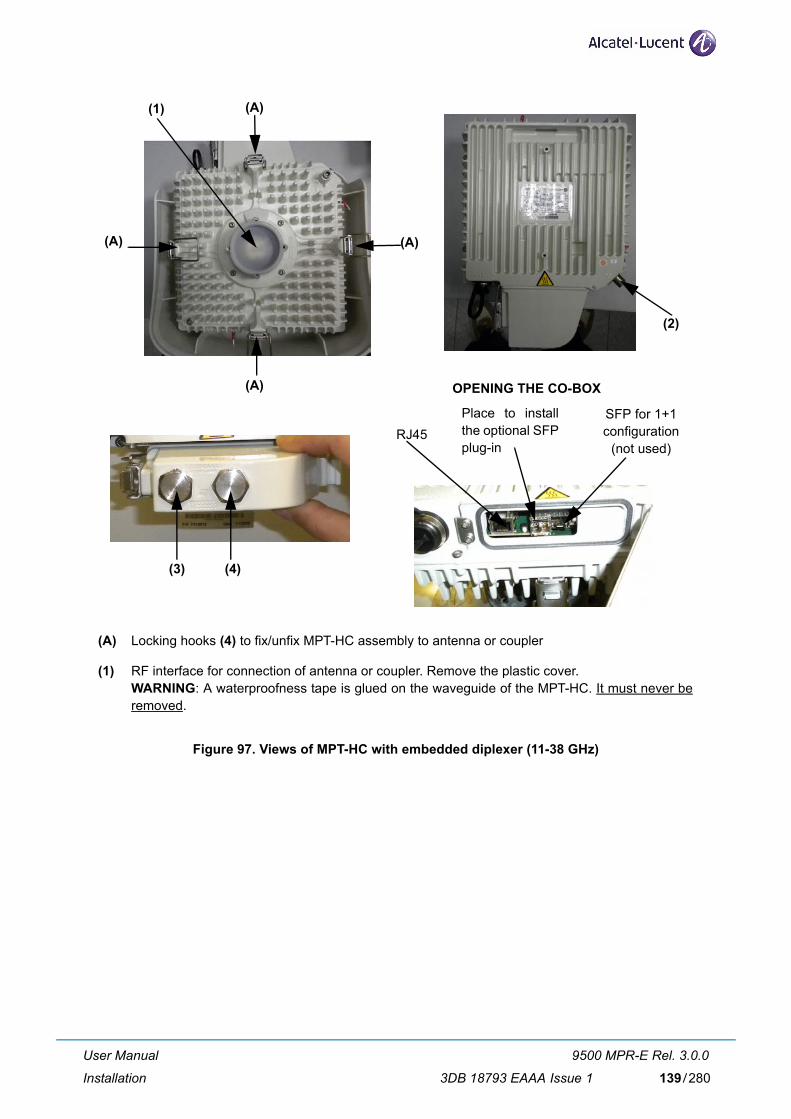
(1) (A)
(A)(A)
(A)
(2)
(3) (4)
RJ45SFP for 1+1 configuration
(not used)
Place to install the optional SFP plug-in
OPENING THE CO-BOX
(A) Locking hooks (4) to fix/unfix MPT-HC assembly to antenna or coupler
(1) RF interface for connection of antenna or coupler. Remove the plastic cover.WARNING: A waterproofness tape is glued on the waveguide of the MPT-HC. It must never be removed.
Figure 97. Views of MPT-HC with embedded diplexer (11-38 GHz)
User Manual
Installation
9500 MPR-E Rel. 3.0.0
3DB 18793 EAAA Issue 1 139/280

(1) (A)
(A)(A)
(A)(2)
(B)(B)
(B)(B)
(3)
(4)
SFP for 1+1 configuration(not used)
Place to install the optional SFP for optical connection
OPENING THE CO-BOX
RJ45 for electrical connection
(A) 4 locking hooks to fix/unfix branching assembly (diplexer) to transceiver
(B) 4 locking hooks to fix/unfix branching assembly (diplexer) to antenna or coupler
(1) RF interface for connection of antenna or coupler. Remove the plastic cover.WARNING: A waterproofness tape is glued on the waveguide of the MPT-HC. It must never be removed.
Figure 98. Views of MPT-HC with external diplexer (7 GHz and 8 GHz)
User Manual
Installation
9500 MPR-E Rel. 3.0.0
3DB 18793 EAAA Issue 1140/280
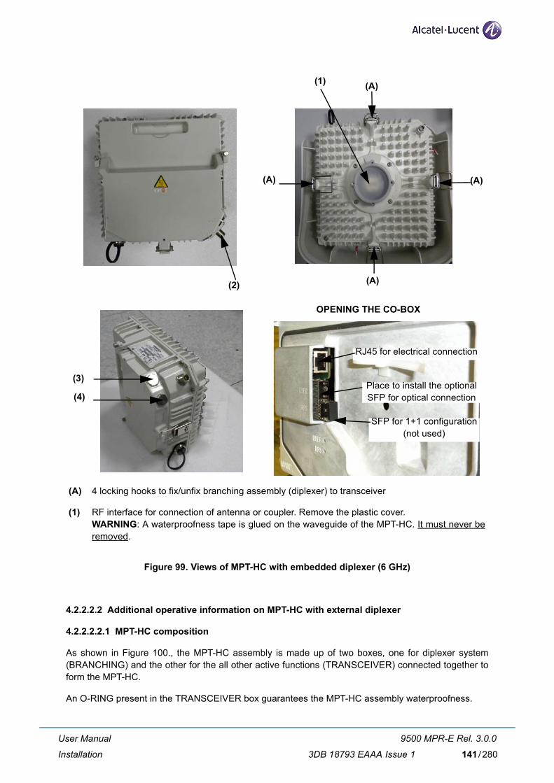
(1) (A)
(A)(A)
(A)(2)
(3)
(4)
SFP for 1+1 configuration(not used)
Place to install the optional SFP for optical connection
OPENING THE CO-BOX
RJ45 for electrical connection
(A) 4 locking hooks to fix/unfix branching assembly (diplexer) to transceiver
(1) RF interface for connection of antenna or coupler. Remove the plastic cover.WARNING: A waterproofness tape is glued on the waveguide of the MPT-HC. It must never be removed.
Figure 99. Views of MPT-HC with embedded diplexer (6 GHz)
4.2.2.2.2 Additional operative information on MPT-HC with external diplexer
4.2.2.2.2.1 MPT-HC composition
As shown in Figure 100., the MPT-HC assembly is made up of two boxes, one for diplexer system (BRANCHING) and the other for the all other active functions (TRANSCEIVER) connected together to form the MPT-HC.
An O-RING present in the TRANSCEIVER box guarantees the MPT-HC assembly waterproofness.
User Manual
Installation
9500 MPR-E Rel. 3.0.0
3DB 18793 EAAA Issue 1 141/280

N.B. This is a conductive O-RING and must be left dry. Do not wet it with silicon grease (silicon grease must be used only on O-ring between MPT-HC and antenna).
BRANCHING TRANSCEIVER
WARNING 1 WARNING 2
Figure 100. Composition of MPT-HC with external diplexer
WARNING 1: A waterproofness tape is glued on the waveguide of the MPT-HC. It must never be removed.
WARNING 2: This gasket must never be removed.
The TRANSCEIVER box performs all the functions, but does not include the diplexer system.
The BRANCHING box provides the interface between the pole mounting/antenna and the TRANS-CEIVER.
The favorite solution foresees the possibility to change in field a spare part TRANSCEIVER without dis-connecting the BRANCHING box from the pole mounting/antenna. The TRANSCEIVER and BRANCH-ING boxes fixing and unfixing are obtained through the four levers.
4.2.2.2.2.2 TRANSCEIVER and BRANCHING boxes coupling
Figure 101. below shows the TRANSCEIVER and BRANCHING boxes coupling surfaces:
– (A) BRANCHING box label informative contentdescribed in Figure 104. on page 145
– (B) (HIGH FREQ) and (C) (LOW FREQ) RF interfaces on BRANCHING box
– (D) (TX) and (E) (RX) RF interfaces on TRANSCEIVER box
The TRANSCEIVER and BRANCHING boxes can be coupled in two alternative ways (180°-rotated with respect to each other):
User Manual
Installation
9500 MPR-E Rel. 3.0.0
3DB 18793 EAAA Issue 1142/280

– BRANCHING box (B) (HIGH FREQ) coupled to TRANSCEIVER box’s (D) (TX)in this case the TX part of the transceiver uses the HIGH frequency range of the Shifter set by the Craft Terminal (see field D in Figure 104. on page 145); obviously the RX part of the transceiver uses the corresponding LOW frequency range;
– BRANCHING box (C) (LOW FREQ) coupled to TRANSCEIVER box’s (D) (TX)in this case the TX part of the transceiver uses the LOW frequency range of the Shifter set by the Craft Terminal (see field D in Figure 104. on page 145); obviously the RX part of the transceiver uses the corresponding HIGH frequency range.
(A) (B)
(C)
(D)
(E)
Figure 101. MPT-HC TRANSCEIVER and BRANCHING boxes coupling surfaces
N.B. There is only one possible way to couple the BRANCHING box and the TRANSCEIVER box: there is a mistake-proofing put by the factory on the TRANSCEIVER box, whose position depends on the type of transceiver (low or high band, as shown in Figure 102.) to ensure that the association with the BRANCHING box is always the right one.
Hole
Mistake-proofing
Figure 102. 6-7-8 GHz MPT-HC BRANCHING box mistake-proofing
User Manual
Installation
9500 MPR-E Rel. 3.0.0
3DB 18793 EAAA Issue 1 143/280

4.2.2.2.3 Labels affixed on the MPT-HC
a) The label depicted in Figure 103. below is affixed externally to all types of MPT-HC and MPT-HC TRANSCEIVER boxes;
b) Only for MPT-HC with external diplexers, an additional label, depicted in Figure 104. on page 145, is placed on the branching assembly.
SYMBOL OR WRITING MEANING
9500-MPR Equipment Acronym & Alcatel-Lucent Logo
CE European Community logo
! Not harmonized frequency logo
2002/96/EC WEEE (Waste Electrical and Elec-tronic Equipment) Logo
-28 V / -58 V 1,6 A / 0,8 A Power supply range and current range
Logistical Item (shown numbers as examples) Logistical Item for Customer
A Logistical Item for Customer, bar code 128
Serial n° (shown numbers as examples) Factory Serial number
B Factory Serial number bar code 128
TX Frequency MHz (shown numbers as examples) Working frequency range
Shifter MHz (shown numbers as examples) Shifter
TX Sub-band (shown numbers as examples) TX Sub-band
Initial SW/ICS (shown numbers as examples) P/N and ICS of the software loaded in factory
PN/ICS (shown numbers as examples) Factory P/N + ICS
C Factory P/N + ICS bar code 128
Figure 103. Label affixed on the MPT-HC and MPT-HC TRANSCEIVER box
User Manual
Installation
9500 MPR-E Rel. 3.0.0
3DB 18793 EAAA Issue 1144/280

N.B. In the label A9400 is written because the diplexers are also used in A9400 AWY.
SYMBOL OR WRITING MEANING
A9400 Equipment Acronym & Alcatel-Lucent Logo
CE European Community logo
12345 (example) Notified body
! Not harmonized frequency logo
2002/96/EC WEEE (Waste Electrical and Elec-tronic Equipment) Logo
PN/ICS 3DB 06775 AAAA 01 (example) Factory Technical Code + ICS
A Factory Technical Code + ICS, bar code 128
Logistical Item 3DB 06775 AAXX (example) Logistical Item for Customer
B Logistical Item for Customer, bar code 128
S/N CW 050609001 (example) Factory Serial number
C Factory Serial number bar code 128
D (shown numbers as examples) – the field “Shifter MHz” indicates the possible frequency bands that can be used with this branching assembly. The choice between different shifters is done byCraft Terminal;
– for each “Shifter MHz”, the TX “LOW” and “HIGH” rows indicate the frequency range assumed by transceiver TX section, accord-ing to the TRANSCEIVER and BRANCHING boxes coupling.
Figure 104. Label affixed inside the MPT-HC BRANCHING box
User Manual
Installation
9500 MPR-E Rel. 3.0.0
3DB 18793 EAAA Issue 1 145/280
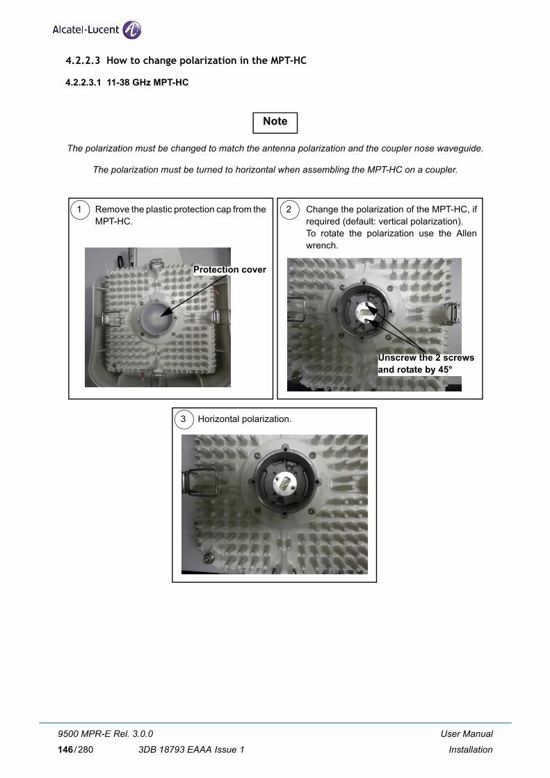
4.2.2.3 How to change polarization in the MPT-HC
4.2.2.3.1 11-38 GHz MPT-HC
1 2
3
Remove the plastic protection cap from the MPT-HC.
Change the polarization of the MPT-HC, if required (default: vertical polarization).To rotate the polarization use the Allen wrench.
Horizontal polarization.
Protection cover
Unscrew the 2 screwsand rotate by 45°
The polarization must be changed to match the antenna polarization and the coupler nose waveguide.
The polarization must be turned to horizontal when assembling the MPT-HC on a coupler.
Note
User Manual
Installation
9500 MPR-E Rel. 3.0.0
3DB 18793 EAAA Issue 1146/280

4.2.2.3.2 6-7-8 GHz MPT-HC
These MPT-HC have fixed polarization (vertical polarization). To change the polarization it is necessary to change the antenna polarization and to install the MPT-HC 90° rotated.
1 2Example of vertical polarization. Example of horizontal polarization.
User Manual
Installation
9500 MPR-E Rel. 3.0.0
3DB 18793 EAAA Issue 1 147/280

4.2.2.4 Types of Pole Mounting Installation kits
– Integrated antenna Pole Mounting Installation kits
– "Pole Mounting for Remote ODU" Installation kits
4.2.2.4.1 Integrated antenna Pole Mounting Installation kits
These integrated antenna Pole Mounting kits are designed for quick mechanical installation, and:
– are included inside the chosen antenna kit.
– foresee the “Fine Tuning” for the positioning of the Antenna.
As shown in Figure 105., these integrated antenna Pole Mounting kits are supplied with the frequency-specific nose adapter for mounting the frequency-specific MPT-HC transceiver or RF Coupler.
In general, the nose adapter:
– in case of smallest antennas, is already mounted on the antenna
– in case of largest antennas, is supplied separately, and must be mounted on the antenna during the installation procedure.
Figure 105. Example of integrated antenna Pole Mounting (with antenna and nose adapter)
User Manual
Installation
9500 MPR-E Rel. 3.0.0
3DB 18793 EAAA Issue 1148/280

4.2.2.4.2 "Pole Mounting for Remote ODU" Installation kits
These kits are frequency independent, and provide only the mechanical support function. The frequency specialization is obtained mounting the frequency-specific nose adapter.
N.B.: The nose adapter shown is not included in the kit.
Figure 106. "Pole Mounting for Remote ODU" Installation kit (3DB10137AAXX)
4.2.2.5 Types of nose adapters
In case of:
– integrated antenna configurations, the nose adapter is delivered inside the chosen antenna kit; in this case the RF interface is used to attach the frequency-specific MPT-HC transceiver or RF Cou-pler.
– Non Integrated Antenna configurations, the nose adapter is used to attach:
• at one side, the frequency-specific MPT-HC transceiver or RF Coupler
• at the other side, to attach the Flextwist cable toward the antenna.
In these Non Integrated Antenna configurations, the nose adapter is delivered as individual item, and must be always mounted on the ODU or Coupler, during the installation procedure.
The mounting accessories are delivered with the nose adapter.
User Manual
Installation
9500 MPR-E Rel. 3.0.0
3DB 18793 EAAA Issue 1 149/280

4.2.2.6 1+0 MPT-HC installation (integrated antenna) - all frequencies
[1] Check/Set the coupling between the TRANSCEIVER and BRANCHING boxes (only for MPT-HC with external diplexer).
[2] Install the Antenna and Pole Mounting.This pole mounting is delivered as “pole mounting”, “antenna”, and frequency-specific “nose adapter” already assembled. The integrated antenna is mounted on the pole front.Antenna and pole mounting must be installed in accordance with the manufacturer’s instructions.
[3] Check or change the polarization on the Antenna nose.To change the polarization, follow the instructions supplied with each antenna. Figure below shows an example.
N.B. The antennas are normally supplied with vertical polarization.
Figure 107. Example of antenna polarization change (“1+0” MPT-HC integrated antenna)
[4] Take off the solar shield from the MPT-HC transceiver by unscrewing the screws placed on the solar shield back panel.
[5] Install the MPT-HC on the Antenna nose adapter.
N.B. Before inserting the MPT-HC on nose adapter, it is mandatory to put SILICONE grease on the O-ring.
User Manual
Installation
9500 MPR-E Rel. 3.0.0
3DB 18793 EAAA Issue 1150/280

Putting silicone grease
Figure 108. Putting silicone grease on O-ring before MPT-HC insertion
1) Grasp the MPT-HC module by the handle.
2) Open the four looking hooks (1) arranged on the four walls of the MPT-HC unit.
3) For 6-7-8 GHz MPT-HC only rotate the MPT-HC depending on the horizontal or vertical polar-ization, and slide it on the nose adapter.
4) Secure the MPT-HC module through the four hooks (1) on the relative brackets (2).
(1) Hook
(2) Bracket
Figure 109. MPT-HC 1+0 installation for integrated antenna (11-38 GHz)
N.B. For 11-38 GHz MPT-HC remember to set first the correct polarization.
User Manual
Installation
9500 MPR-E Rel. 3.0.0
3DB 18793 EAAA Issue 1 151/280

(1) Hook
(2) Bracket
Figure 110. MPT-HC 1+0 installation for integrated antenna (6-7-8 GHz: vertical polarization)
(1) Hook
(2) Bracket
Figure 111. MPT-HC 1+0 installation for integrated antenna (6-7-8 GHz: horizontal polarization)
REMINDER: The MPT-HC/antenna assembly requires no additional seal on the SHF flanges; the two ends are smooth. The O-ring seal around the male “nose” provides sealing.
[6] Ground the MPT-HC system.
[7] Pre-point the antenna.
[8] Reinstall the solar shield onto the MPT-HC transceiver by screwing on it the solar shield screws.
[9] Affix the EMF stickers.
User Manual
Installation
9500 MPR-E Rel. 3.0.0
3DB 18793 EAAA Issue 1152/280

4.2.2.7 1+0 MPT-HC installation (non integrated antenna) - all frequencies
[1] Check/Set the coupling between the TRANSCEIVER and BRANCHING boxes (only for MPT-HC with external diplexer).
[2] Install the Nose Adapter on the “Pole Mounting for Remote ODU”.
[3] Install the “Pole Mounting for Remote ODU”.Pole mounting must be installed in accordance with the manufacturer’s instructions.In case of missing instructions, fix the U-bolts with 34 N x m tightening torque.
N.B. The pole mounting can be installed on the Right or Left hand side of the pole depending on the azimuth and on the configuration of the tower.
Figure 112. "Pole Mounting for Remote ODU" installation
[4] Take off the solar shield from the MPT-HC transceiver by unscrewing the screws placed on the solar shield back panel.
[5] Install the MPT-HC.
N.B. Before inserting the MPT-HC on nose adapter, it is mandatory to put SILICONE grease on the O-ring.
Putting silicone grease
Figure 113. Putting silicone grease on O-ring before MPT-HC insertion
1) Grasp the MPT-HC module by the handle. Open the four looking hooks arranged on the four walls of the MPT-HC unit.
2) Position the Pole mounting support on the pole side as shown in the plant documentation.
User Manual
Installation
9500 MPR-E Rel. 3.0.0
3DB 18793 EAAA Issue 1 153/280

3) Position the MPT-HC and slide it on the nose adapter.
4) Secure the MPT-HC module through the four hooks onto the relative brackets.
Figure 114. MPT-HC 1+0 installation for not integrated antenna (11-38 GHz with pole mounting P/N 3DB 10137 AAAB)
Figure 115. MPT-HC 1+0 installation for not integrated antenna (6-7-8 GHz with pole mounting P/N 3DB10137AAXX)
[6] Install the external Antenna with its own Pole Mounting.The installation of the antenna and of its own pole mounting, as well as the antenna polarization check/change, must be done in accordance with the manufacturer’s instructions.
[7] Connect the antenna side (flange) of the Pole Mounting’s nose adapter to the external antenna, by means of the “Flextwist“ waveguide.
[8] Ground the MPT-HC system.
[9] Pre-point the antenna.
[10] Reinstall the solar shield onto the MPT-HC transceiver by screwing on it the solar shield screws.
[11] Affix the EMF stickers.
User Manual
Installation
9500 MPR-E Rel. 3.0.0
3DB 18793 EAAA Issue 1154/280

4.2.2.8 How to pull up the cables from indoor to the MPT-HC
4.2.2.8.1 Optical fiber
1 2
3 4
Take the optical fiber cable of the suitable length.
Take the Hoisting grip tool.
Insert the fiber in the hoisting grip tool.
5 6Screw the gland body to the hoisting grip until the end of stroke with a fixed spanner.
7 8 Fix the gland nut with the dynamometric wrench (10N).
Gland nutGland body
User Manual
Installation
9500 MPR-E Rel. 3.0.0
3DB 18793 EAAA Issue 1 155/280

9 10Take a cord and insert it in the hoisting grip tool.
Make a knot on the cord and pull up with the cord the hoisting grip tool.
11 The overlength of the optical fiber must be rolled up in the Cable overlength box.
User Manual
Installation
9500 MPR-E Rel. 3.0.0
3DB 18793 EAAA Issue 1156/280

4.2.2.8.2 Electrical Ethernet cable
N.B. The cable must be terminated on field.
N.B. Install the gland before terminating the cable.
4 5Take the terminated electrical cable and protect the RJ45 with a tape.
1 Inser the gland on the cable: first insert the gland nut, then the gland seal, last the gland body.
Terminate the Ethernet cable with the RJ45 connector (1AB074610027) according to the plug assembling instructions included in the relevant tool provided in the Special tool bag (3CC50098AAAA).
2
Gland body Gland seal Gland nut
3 Terminate the Ethernet cable acording to EIA/TIA 568B STANDARD
User Manual
Installation
9500 MPR-E Rel. 3.0.0
3DB 18793 EAAA Issue 1 157/280

8 9Sign 1.5 cm from the reference. Sign 3 cm from the reference.
10 11Remove the sheath of the cable from 1.5 cm to 3 cm from the reference.
Insert the cable in the hoisting grip tool.
6 7 Take a 35 cm reference on the cable.
User Manual
Installation
9500 MPR-E Rel. 3.0.0
3DB 18793 EAAA Issue 1158/280

Make a knot on the cord and pull up with the cord the hoisting grip tool.
18
Take a cord and insert it in the hoisting grip tool.
14 15
16 17
Gland nut
Fix the gland nut with the dynamometric wrench (10N).
12 13Insert the cable in the hoisting grip tool. Screw the gland body to the hoisting grip until the end of stroke with a fixed spanner.
Gland body
User Manual
Installation
9500 MPR-E Rel. 3.0.0
3DB 18793 EAAA Issue 1 159/280
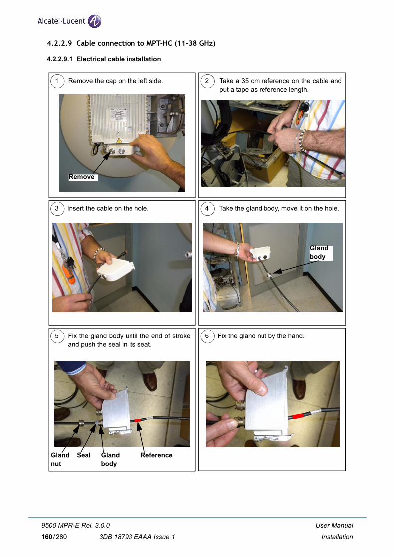
4.2.2.9 Cable connection to MPT-HC (11-38 GHz)
4.2.2.9.1 Electrical cable installation
1 2
3 4
5 6
Remove the cap on the left side. Take a 35 cm reference on the cable and put a tape as reference length.
Insert the cable on the hole. Take the gland body, move it on the hole.
Glandbody
Fix the gland body until the end of stroke and push the seal in its seat.
Fix the gland nut by the hand.
Remove
Glandnut
Glandbody
Seal Reference
User Manual
Installation
9500 MPR-E Rel. 3.0.0
3DB 18793 EAAA Issue 1160/280

Make a loop on the cable.
Remove the tape from the RJ45 connector. 10
11
Climp the yellow boot on the cable.
Put the boot on the RJ45 connector. 12
9
Boot
7 8Pull back the cable until the reference is visible near the gland nut.
Tighten the body and then the gland nut with the dynamometric wrench (10 N).
User Manual
Installation
9500 MPR-E Rel. 3.0.0
3DB 18793 EAAA Issue 1 161/280

15 End of cable connection.
13 14 Connect the RJ45 connector on the MPT-HC connector and close the co-box.
Position of the cable with loop.
Warning: The Power Supply connection must be made waterproof:
1) Surround the connector with the auto amalgamate tape from up to down
2) Surround the connector with the adhesive tape from up to down
3) Put tie raps on the up and the down of the connector
User Manual
Installation
9500 MPR-E Rel. 3.0.0
3DB 18793 EAAA Issue 1162/280

4.2.2.9.2 Optical fiber cable installation
1 2
3 4
5 6
Insert the SFP on the MPT-HC. Insert the optical fiber on the hole.
Gland
Fix the gland body.Take the gland body and move it on the hole.
Tighten the gland nut with the dynamometric wrench.
Remove the protection caps from the fiber connectors.
Warning: The end of the heat-shrink tube reference must be outside the gland.
Reference
User Manual
Installation
9500 MPR-E Rel. 3.0.0
3DB 18793 EAAA Issue 1 163/280

7 8
9
Take the optical conectors and ... ... connect them on the MPT-HC. Close the co-box.
End of optical fiber connection.
Warning: The Power Supply connection must be made waterproof:
1) Surround the connector with the auto amalgamate tape from up to down
2) Surround the connector with the adhesive tape from up to down
3) Put tie raps on the up and the down of the connector
User Manual
Installation
9500 MPR-E Rel. 3.0.0
3DB 18793 EAAA Issue 1164/280

4.2.2.10 Cable connection to MPT-HC (6-7-8 GHz)
4.2.2.10.1 Electrical cable installation
1 2
3 4
6
Open the co-box.
Move the gland nut and tighten it with the dynamometric wrench.
End of cable connection.5 Insert the yellow boot on the RJ45 connector and insert it in the co-box. Close the co-box.
Remove the cap from “User” and insert the cable on the hole. Tighten the gland body with the dynamometric wrench.
User
Gland nut
Take a 29 cm reference on the cable and put a tape as reference length.
User Manual
Installation
9500 MPR-E Rel. 3.0.0
3DB 18793 EAAA Issue 1 165/280

4.2.2.10.2 Optical fiber cable installation
1 2
3 4
5 6
Open the co-box. Insert the SFP module.
Move the gland body and tighten it with the dynamometric wrench.
Remove the cap from “User” and insert the optical fiber on the hole.
Tighten the gland nut with the dynamometric wrench.
Remove the protection caps from the fiber connectors, insert them in the SFP. Close the co-box.
Warning: The reference must be outside the co-box and the gland nut.
User Manual
Installation
9500 MPR-E Rel. 3.0.0
3DB 18793 EAAA Issue 1166/280

7 End of optical fiber connection.
User Manual
Installation
9500 MPR-E Rel. 3.0.0
3DB 18793 EAAA Issue 1 167/280

4.2.2.11 Installing the “Flextwist“ waveguide (not integrated antenna cases)
Concerning the interface between the MPT-HC output flange and the suggested antenna flange, the fol-lowing Table 24. details for each product the standard wave guide to be used and the suggested flange for the external antenna.
Please note that the use of 600 mm flex twist is not suggested for antennas bigger than 3ft (90 cm diam-eter), due to mechanical reasons. The suggested way to make the RF connection is to use the elliptical wave guide fitted with flanged connectors.
Table 24. MPT-HC Output flanges with external antenna
Range (GHz)
MPT-HC Output Flange
FLEXTWIST Suggested Antenna Flange
C.E.I. E.I.A.
6 UBR70 R70 WR137 PDR70 UDR70 PDR70
7-8
UDR84 R84 WR112 PDR84 UBR84 PBR84
or
UBR84 R84 WR112 PBR84 UBR84 PBR84
11 UBR100 R100 WR90 PBR100 UBR100 PBR100
13 UBR120 R120 WR75 PBR120 UBR120 PBR120
15 UBR140 R140 WR62 PBR140 UBR140 PBR140
18
UBR220 R220 WR42 PBR220 UBR220 PBR22023
26
38 UBR320 R320 WR28 PBR320 UBR320 PBR320
The long twistable flexible waveguide is supplied complete with gaskets and fasteners. At one end, it has a smooth square or rectangular flange (to be mounted on the antenna) and at the other end, a grooved square flange designed to accommodate an O–ring seal (mounted at the MPT-HC end).
User Manual
Installation
9500 MPR-E Rel. 3.0.0
3DB 18793 EAAA Issue 1168/280

Table 25. 6-7-8GHz Flextwist waveguide
FLEXIBLE TWISTABLE WAVEGUIDE KIT
Alc
atel
-Luc
ent c
ode
Wav
egui
de
Leng
th m
m.
Freq
. Ban
d G
Hz
Flan
ges
Stai
nles
s st
eel
sock
et c
ap s
crew
s
Stai
nles
s st
eel
sock
et c
ap s
crew
s
“Ond
ufle
x” s
prin
gy
crin
kle
was
hers
Stai
nles
s Z.
fla
t was
hers
HM
. Hex
nut
s
1AF02951ABAA WR137 1000 6 PDR70 UDR70 8 (M4x25)
8 (M4x12)
8 (B4)
8 (Z4)
8 (HM4)
3CC08010ABAB WR112 1000 7,05–10 PBR84 UBR84 8 (M4x25)
8 (M4x12)
8 (B4)
8 (Z4)
8 (HM4)
Table 26. 11-38GHz Flextwist waveguide
FLEXIBLE TWISTABLE WAVEGUIDE KIT
Alc
atel
-Luc
ent c
ode
Wav
egui
de
Leng
th m
m.
Freq
. Ban
d G
Hz
Flan
ges
Stai
nles
s st
eel
sock
et c
ap s
crew
s
Stai
nles
s st
eel
sock
et c
ap s
crew
s
“Ond
ufle
x” s
prin
gy
crin
kle
was
hers
Stai
nles
s Z.
fla
t was
hers
HM
. Hex
nut
s
1AF02957ABAA WR90 1000 11 PBR100 UBR100 8 (M4x20)
8 (M4x12)
8 (B4)
12 (Z4)
12 (HM4)
3CC05751ACAA WR75 600 10 – 15,0 PBR120 UBR120 8 (M4x20)
8 (M4x12)
8 (B4)
12 (Z4)
12 (HM4)
3CC05750ACAA WR62 600 12,4 – 18 PBR140 UBR140 8 (M4x20)
8 (M4x12)
8 (B4)
8 (Z4)
8 (HM4)
3CC05749ACAA WR42 600 18 – 26,5 PBR220 UBR220 8 (M3x20)
8 (M3x12)
8 (B3)
8 (Z3)
8 (HM3)
3DB00682AAAA WR28 600 26,5 – 40 PBR320 UBR320 8 (M3x20)
8 (M3x12)
8 (B3)
8 (Z3)
8 (HM3)
N.B. If the FLEX–TWIST is not provided by Alcatel, the user must carefully choose the type of the connection guide in order to limit as much as possible galvanic couples between ANTENNA/flex–twist and flex–twist/MPT-HC contact surfaces that can induce rust. For this purpose please note that the surfaces are:
– chromium-plated at MPT-HC output flange side
– tin-plated at flex-twist’s flange side
User Manual
Installation
9500 MPR-E Rel. 3.0.0
3DB 18793 EAAA Issue 1 169/280

4.2.2.12 MPT-HC system grounding
Each MPT-HC transceiver must be individually grounded.
N.B. Neither the RF coupler, nor the antenna(s), integrated or not integrated, must be grounded.
The following items are necessary for the individual grounding of each MPT-HC transceiver:
– one MPT-HC Grounding Kit (P/N 3CC08166AAXX). This kit corresponds to a cable (16mm2 L = 15 m) that must be cut on site and connected to the ter-minal provided on the MPT-HC transceiver, and, on the other side, to the nearest grounding plate;
This example figure shows the grounding connector position.
MPT-HC grounding connector:to be connected with thegrounding cable to the nearestgrounding plate
Connect all grounding cables to the nearest grounding plate, as shown in this example:
User Manual
Installation
9500 MPR-E Rel. 3.0.0
3DB 18793 EAAA Issue 1170/280

4.2.2.13 Cable Grounding
The Power Supply cable and the Ethernet electrical cable must be grounded by using the dedicated Grounding kits.
For ground kit installation instructions refer to the guide provided with each kit.
For tower/mast installations the cables must be grounded at:
– The point where it comes on to the tower from the MPT-HC
– The point where it leaves the tower to go to the equipment building
– Not more than 25 m intervals on the tower if the height on the tower exceeds 50 m
– A point just prior to building entry
Figure 116. shows typical tower locations for cable grounding.
Note: All the cables (coax cable, Cat5e cable, fiber cable) must be fixed to the tower with the relevant ties.
At non-standard installations, such as building tops or the sides of buildings, follow the same general guidelines but where proper grounding points are not provided these must first be installed.
MPT & antenna
Cable ground
MPT ODU ground wire
Cable ground Cable ground
Cable carrier
ground bar
Site grounding
Rack ground bar
Cable supported by black cable ties at not more than 1 m intervals. Must not run adjacent to tower lightning ground or electrical cables
Install additional cable grounds at not more than 25 m intervals if the height of cable on the tower exceeds 50 m
Figure 116. Locations for Cable Grounds
User Manual
Installation
9500 MPR-E Rel. 3.0.0
3DB 18793 EAAA Issue 1 171/280

4.2.2.14 Type N connectors and Grounding kits waterproofing on the IDU/ODU cables
For installation on the type N connectors and grounding kits please refer to the installation notice provided with the connector and the grounding kit.
IMPORTANT:
To prevent potential risks of dysfunction it is recommended and a particular attention will be carried in the realization of the waterproofing of connectings (see following page).For the holding in the bad weather, do not forget the waterproofing at the end of the operation with the Self auto-amalgamating + UV protection vinyl tape by necklaces Colson / Tie raps in every extremity.For the assembly between the cable, grounding kit and ODU realized outside, it is recommended to use the Self auto-amalgamating (several turns) to assure the waterproofing. Then to cover the set by the UV protection vinyl tape to avoid the unsticking of the self-amalgamating and ended with a necklace Colson / Tie raps.
4.2.2.14.1 Example of Connector N waterproofing
4.2.2.14.2 Example of N Connector & Waterproofing
The principle of waterproofing given above is valid for the connections cable / ODU and for the grounding kits of the coaxial cable. It is recommended to make this waterproofing by "dry" weather, to avoid locking the humidity into the system.
Surround the connector with the adhesive UV tape from up to down
Surround the connector with the auto amalgamate tape from up to down
User Manual
Installation
9500 MPR-E Rel. 3.0.0
3DB 18793 EAAA Issue 1172/280
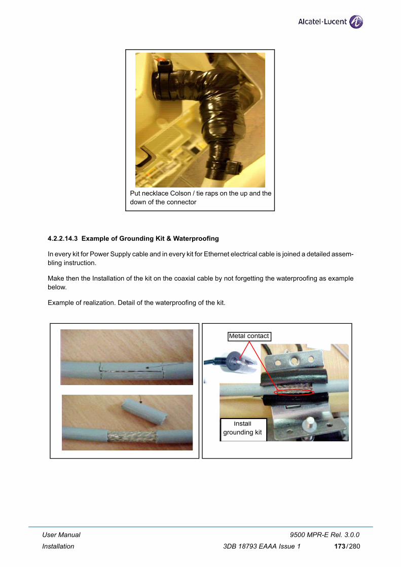
Put necklace Colson / tie raps on the up and the down of the connector
4.2.2.14.3 Example of Grounding Kit & Waterproofing
In every kit for Power Supply cable and in every kit for Ethernet electrical cable is joined a detailed assem-bling instruction.
Make then the Installation of the kit on the coaxial cable by not forgetting the waterproofing as example below.
Example of realization. Detail of the waterproofing of the kit.
Metal contact
Install grounding kit
User Manual
Installation
9500 MPR-E Rel. 3.0.0
3DB 18793 EAAA Issue 1 173/280

Waterproofing with Almagamating + UV protection vinyl tape + Necklace Colson / Tie rap
Thighten with allen key 8 mm
User Manual
Installation
9500 MPR-E Rel. 3.0.0
3DB 18793 EAAA Issue 1174/280

4.2.3 MPT-HC V2 Installation
The MPT-HC installation section is divided in:
– Types of MPT-HC V2 (par. 4.2.3.1 on page 176)
– External module to be installed (par. 4.2.3.2 on page 177)
– MPT-HC V2 operative information (par. 4.2.3.3 on page 180)
– How to change polarization in the MPT-HC V2 (par. 4.2.3.4 on page 185)
– Types of Pole Mounting Installation kits (par. 4.2.3.5 on page 185)
– Types of nose adapters (par. 4.2.3.6 on page 185)
– 1+0 MPT-HC V2 installation (integrated antenna) (par. 4.2.3.7 on page 185)
– 1+0 MPT-HC V2 installation (non integrated antenna) (par. 4.2.3.8 on page 185)
– Cable connections (MPT-HC V2 to MSS) (par. 4.2.3.9 on page 185)
– Installing the “Flextwist“ waveguide (not integrated antenna cases) (par. 4.2.3.10 on page 186)
– MPT-HC V2 system grounding (par. 4.2.3.11 on page 186)
– Cable Grounding (par. 4.2.3.12 on page 186)
User Manual
Installation
9500 MPR-E Rel. 3.0.0
3DB 18793 EAAA Issue 1 175/280
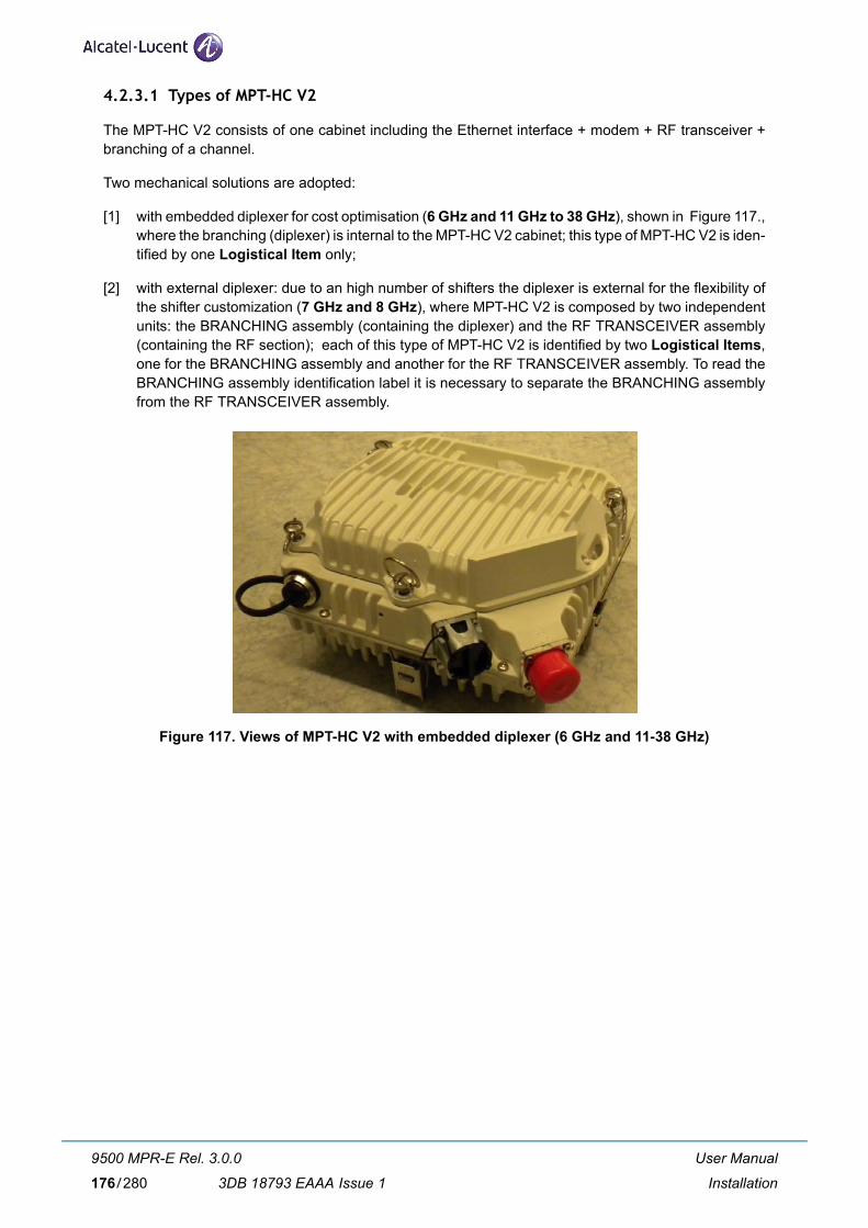
4.2.3.1 Types of MPT-HC V2
The MPT-HC V2 consists of one cabinet including the Ethernet interface + modem + RF transceiver + branching of a channel.
Two mechanical solutions are adopted:
[1] with embedded diplexer for cost optimisation (6 GHz and 11 GHz to 38 GHz), shown in Figure 117., where the branching (diplexer) is internal to the MPT-HC V2 cabinet; this type of MPT-HC V2 is iden-tified by one Logistical Item only;
[2] with external diplexer: due to an high number of shifters the diplexer is external for the flexibility of the shifter customization (7 GHz and 8 GHz), where MPT-HC V2 is composed by two independent units: the BRANCHING assembly (containing the diplexer) and the RF TRANSCEIVER assembly (containing the RF section); each of this type of MPT-HC V2 is identified by two Logistical Items, one for the BRANCHING assembly and another for the RF TRANSCEIVER assembly. To read the BRANCHING assembly identification label it is necessary to separate the BRANCHING assembly from the RF TRANSCEIVER assembly.
Figure 117. Views of MPT-HC V2 with embedded diplexer (6 GHz and 11-38 GHz)
User Manual
Installation
9500 MPR-E Rel. 3.0.0
3DB 18793 EAAA Issue 1176/280

4.2.3.2 External module to be installed
The MPT-HC V2 is delivered from the factory in one packing-case in the basic configuration (without any external module). The external module (RPS or XPIC+RPS) is delivered in another packing-case.
The external module must be installed in field on the MPT-HC V2.
Note: Before installing an external module (XPIC module or XPIC-RPS module) on a MPT-HC V2, the corresponding MPT-HC V2 must be switched OFF. Switch ON can be done once the module has been properly screwed.
To install it follow the following procedure:
1) Disinstall the solar shield by unlocking the 3 screws.
2) Unlock the 4 screws.
3) Remove the basic cover
Unlock the screws
Remove the cover
4) Remove the cap.
Remove the cap
User Manual
Installation
9500 MPR-E Rel. 3.0.0
3DB 18793 EAAA Issue 1 177/280

5) Withdraw the external module from the packing-case (RPS: refer to Figure 118. or XPIC+RPS: refer to Figure 119.) and remove the cap.
Remove the cap
Bottom view
Top view
Figure 118. RPS module
Remove the cap
Bottom view
Top view
Figure 119. XPIC + RPS module
User Manual
Installation
9500 MPR-E Rel. 3.0.0
3DB 18793 EAAA Issue 1178/280

6) Install the module on the MPT-HC V2 and lock the 4 screws. Pay attenation to the correct posi-tion of the screws, as shown in Figure 120. The slot of the screw must be aligned with the indi-cation on the MPT-HC V2.
Figure 120. External module installed
Indication
Figure 121. Correct screw position
7) Install the solar-shield taking into account the polarization to be used.
User Manual
Installation
9500 MPR-E Rel. 3.0.0
3DB 18793 EAAA Issue 1 179/280

4.2.3.3 MPT-HC V2 operative information
This paragraph gives operative information, for installation regarding:
– MPT-HC V2 with embedded or external diplexer herebelow
– MPT-HC V2 with external diplexer (additional information) on page 182
4.2.3.3.1 Operative information on MPT-HC V2 with embedded or external diplexer
4.2.3.3.1.1 General, views and access points
Figure 122. on page 181 (for MPT-HC V2 with embedded diplexer) and Figure 123. on page 182 (for MPT-HC V2 with external diplexer) show MPT-HC V2 views and access points.
The external interfaces are listed in Table 27. below with the corresponding connectors.
Table 27. MPT-HC V2 external interfaces
Ref. in Figure 122.
and Figure 123.
Interface Connector Further information
(1) RF interface for connection of antenna or coupler Waveguide Table 28. herebelow
(2) Connector for power supply cable or for PFoE (Power Supply + Ethernet Traffic) cable
RJ45 + R2CT
(3) Optical Ethernet connection LC + Q-XCO
(4) Connection to a second MPT-HC V2 in 1+1 LC + Q-XCO
(5) XPIC connector Not used in the current release
Table 28. RF interface
FREQUENCY GHz -> 6 7 8 11 13-15 18-26 38
Waveguide type -> WR137 WR112 WR112 WR75 WR62 WR42 WR28
User Manual
Installation
9500 MPR-E Rel. 3.0.0
3DB 18793 EAAA Issue 1180/280

(1) (A)
(A)(A)
(A)(3) (2)
MPT-HC V2 basic
(4)
(3) (2)
MPT-HC V2 equipped with XPIC-RPS module
(5)
(4)
(3) (2)
MPT-HC V2 equipped with RPS module
(A) Locking hooks (4) to fix/unfix MPT-HC V2 assembly to antenna or coupler
(1) RF interface for connection of antenna or coupler. Remove the plastic cover.WARNING: A waterproofness tape is glued on the waveguide of the MPT-HC V2. It must never be removed.
Figure 122. Views of MPT-HC V2 with embedded diplexer (6 GHz and 11-38 GHz)
User Manual
Installation
9500 MPR-E Rel. 3.0.0
3DB 18793 EAAA Issue 1 181/280

(1) (A)
(A)(A)
(A)
(B)(B)
(B)(B)
(4)
(3) (2)
MPT-HC V2 equipped with RPS module
(4)
(3) (2)
MPT-HC V2 equipped with XPIC-RPS module
(5)
(3) (2)
MPT-HC V2 basic
(A) 4 locking hooks to fix/unfix branching assembly (diplexer) to transceiver
(B) 4 locking hooks to fix/unfix branching assembly (diplexer) to antenna or coupler
(1) RF interface for connection of antenna or coupler. Remove the plastic cover.WARNING: A waterproofness tape is glued on the waveguide of the MPT-HC V2. It must never be removed.
Figure 123. Views of MPT-HC V2 with external diplexer (7 GHz and 8 GHz)
4.2.3.3.2 Additional operative information on MPT-HC V2 with external diplexer
Refer to paragraph 4.2.2.2.2 on page 141.
User Manual
Installation
9500 MPR-E Rel. 3.0.0
3DB 18793 EAAA Issue 1182/280

4.2.3.3.3 Labels affixed on the MPT-HC V2
a) The label depicted in Figure 124. below is affixed externally to all types of MPT-HC V2 and MPT-HC V2 TRANSCEIVER boxes;
b) Only for MPT-HC V2 with external diplexers, an additional label, depicted in Figure 125. on page 184, is placed on the branching assembly.
SYMBOL OR WRITING MEANING
9500-MPR Equipment Acronym & Alcatel-Lucent Logo
CE European Community logo
! Not harmonized frequency logo
2002/96/EC WEEE (Waste Electrical and Elec-tronic Equipment) Logo
-28 V / -58 V 1,5 A / 0,7 A Power supply range and current range
Logistical Item (shown numbers as examples) Logistical Item for Customer
A Logistical Item for Customer, bar code 128
Serial n° (shown numbers as examples) Factory Serial number
B Factory Serial number bar code 128
TX Frequency MHz (shown numbers as examples) Working frequency range
Shifter MHz (shown numbers as examples) Shifter
TX Sub-band (shown numbers as examples) TX Sub-band
Figure 124. Label affixed on the MPT-HC V2 and MPT-HC V2 TRANSCEIVER box
User Manual
Installation
9500 MPR-E Rel. 3.0.0
3DB 18793 EAAA Issue 1 183/280

N.B. In the label A9400 is written because the diplexers are also used in A9400 AWY.
SYMBOL OR WRITING MEANING
A9400 Equipment Acronym & Alcatel-Lucent Logo
CE European Community logo
12345 (example) Notified body
! Not harmonized frequency logo
2002/96/EC WEEE (Waste Electrical and Elec-tronic Equipment) Logo
PN/ICS 3DB 06775 AAAA 01 (example) Factory Technical Code + ICS
A Factory Technical Code + ICS, bar code 128
Logistical Item 3DB 06775 AAXX (example) Logistical Item for Customer
B Logistical Item for Customer, bar code 128
S/N CW 050609001 (example) Factory Serial number
C Factory Serial number bar code 128
D (shown numbers as examples) – the field “Shifter MHz” indicates the possible frequency bands that can be used with this branching assembly. The choice between different shifters is done byCraft Terminal;
– for each “Shifter MHz”, the TX “LOW” and “HIGH” rows indicate the frequency range assumed by transceiver TX section, accord-ing to the TRANSCEIVER and BRANCHING boxes coupling.
Figure 125. Label affixed inside the MPT-HC V2 BRANCHING box
User Manual
Installation
9500 MPR-E Rel. 3.0.0
3DB 18793 EAAA Issue 1184/280

4.2.3.4 How to change polarization in the MPT-HC V2
Refer to paragraph 4.2.2.3 on page 146.
4.2.3.5 Types of Pole Mounting Installation kits
Refer to paragraph 4.2.2.4 on page 148.
4.2.3.6 Types of nose adapters
Refer to paragraph 4.2.2.5 on page 149.
4.2.3.7 1+0 MPT-HC V2 installation (integrated antenna)
Refer to paragraph 4.2.2.6 on page 150.
4.2.3.8 1+0 MPT-HC V2 installation (non integrated antenna)
Refer to paragraph 4.2.2.7 on page 153.
4.2.3.9 Cable connections (MPT-HC V2 to MSS)
4.2.3.9.1 Electrical Ethernet cable
If the PFoE has been implemented, only one cable interconnects the MPT-HC V2 with the MSS. Refer to paragraph 4.2.4.8 on page 203.
4.2.3.9.2 Optical cable connection
An optical cable must be used, if the PFoE has not been implemented.
The cable is shown in Figure 126. The cable is a preassembled cable available in different lengths (refer to paragraph 4.2.7.3 on page 213).
Figure 126. Q-XCO to Q-XCO Fiber cord
To pull-up the cable take a cord and insert it in the slot of the cable cap. Make a knot on the cord and pull-up the cable.
Remove the cap and connect the connector to the Q-XCO connector in the MPT-HC V2.
User Manual
Installation
9500 MPR-E Rel. 3.0.0
3DB 18793 EAAA Issue 1 185/280

4.2.3.9.3 Power supply cable connection
The power supply cable is a coaxial cable, which is used only if the optical cable is used to transport the Ethernet traffic. Two types of coaxial cables are available according to the length (less than 200 m or more than 200 m).
The coaxial cable must be connected to:
– IDU-side to the MPT Access unit;
– ODU-side to the 1 m cord adapter (from N female to RJ45 plug). The RJ45 must be then connected to the relevant connector on the MPT-HC V2.
4.2.3.10 Installing the “Flextwist“ waveguide (not integrated antenna cases)
Refer to paragraph 4.2.2.11 on page 168.
4.2.3.11 MPT-HC V2 system grounding
Refer to paragraph 4.2.2.12 on page 170.
4.2.3.12 Cable Grounding
Refer to paragraph 4.2.2.13 on page 171.
User Manual
Installation
9500 MPR-E Rel. 3.0.0
3DB 18793 EAAA Issue 1186/280

4.2.4 MPT-MC Installation
The MPT-MC installation section is divided in:
– Types of MPT-MC (par. 4.2.4.1 on page 188)
– MPT-MC operative information (par. 4.2.4.2 on page 189)
– How to change polarization in the MPT-MC (par. 4.2.4.3 on page 196)
– Types of Pole Mounting Installation kits (par. 4.2.4.4 on page 197)
– Types of nose adapters (par. 4.2.4.5 on page 197)
– 1+0 MPT-MC installation (integrated antenna) - all frequencies (par. 4.2.4.6 on page 198)
– 1+0 MPT-MC installation (non integrated antenna) - all frequencies (par. 4.2.4.7 on page 201)
– How to terminate the Ethernet cable (MPT-MC side) and to pull up it from Indoor to MPT-MC (par. 4.2.4.8 on page 203)
– Installing the “Flextwist“ waveguide (not integrated antenna cases) (par. 4.2.4.9 on page 207)
– MPT-MC system grounding (par. 4.2.4.10 on page 207)
– Cable Grounding (par. 4.2.4.11 on page 207)
User Manual
Installation
9500 MPR-E Rel. 3.0.0
3DB 18793 EAAA Issue 1 187/280
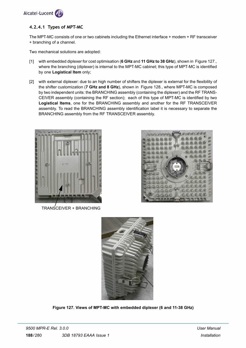
4.2.4.1 Types of MPT-MC
The MPT-MC consists of one or two cabinets including the Ethernet interface + modem + RF transceiver + branching of a channel.
Two mechanical solutions are adopted:
[1] with embedded diplexer for cost optimisation (6 GHz and 11 GHz to 38 GHz), shown in Figure 127., where the branching (diplexer) is internal to the MPT-MC cabinet; this type of MPT-MC is identified by one Logistical Item only;
[2] with external diplexer: due to an high number of shifters the diplexer is external for the flexibility of the shifter customization (7 GHz and 8 GHz), shown in Figure 128., where MPT-MC is composed by two independent units: the BRANCHING assembly (containing the diplexer) and the RF TRANS-CEIVER assembly (containing the RF section); each of this type of MPT-MC is identified by two Logistical Items, one for the BRANCHING assembly and another for the RF TRANSCEIVER assembly. To read the BRANCHING assembly identification label it is necessary to separate the BRANCHING assembly from the RF TRANSCEIVER assembly.
TRANSCEIVER + BRANCHING
Figure 127. Views of MPT-MC with embedded diplexer (6 and 11-38 GHz)
User Manual
Installation
9500 MPR-E Rel. 3.0.0
3DB 18793 EAAA Issue 1188/280

Figure 128. Views of MPT-MC with external diplexer (7 GHz and 8 GHz)
4.2.4.2 MPT-MC operative information
This paragraph gives operative information, for installation regarding:
– MPT-MC with embedded or external diplexer herebelow
– MPT-MC with external diplexer (additional information) on page 191
4.2.4.2.1 Operative information on MPT-MC with embedded or external diplexer
4.2.4.2.1.1 General, views and access points
Figure 129. on page 190 (for MPT-MC with embedded diplexer) and Figure 130. on page 190 (for MPT-MC with external diplexer) show MPT-MC views and access points.
The external interfaces are listed in Table 29. below, with the corresponding connector.
Table 29. MPT-MC external interfaces
Ref. in Figure 129.
and Figure 130.
Interface Connector Further information
(1) RF interface for connection of antenna or coupler waveguide Table 30. herebelow
(2) Ethernet electrical cable R2CT
Table 30. RF interface
FREQUENCY GHz -> 6 7 8 11 13-15 18-26 38
Waveguide type -> WR137 WR112 WR112 WR75 WR62 WR42 WR28
User Manual
Installation
9500 MPR-E Rel. 3.0.0
3DB 18793 EAAA Issue 1 189/280

(1) (A)
(A)(A)
(A)
(2)
(A) Locking hooks (4) to fix/unfix MPT-MC assembly to antenna or coupler
(1) RF interface for connection of antenna or coupler. Remove the plastic cover.WARNING: A waterproofness tape is glued on the waveguide of the MPT-MC. It must never be removed.
Figure 129. Views of MPT-MC with embedded diplexer (6 and 11-38 GHz)
(1) (A)
(A)(A)
(A)
(B)(B)
(B)(B)(2)
(A) 4 locking hooks to fix/unfix branching assembly (diplexer) to transceiver
(B) 4 locking hooks to fix/unfix branching assembly (diplexer) to antenna or coupler
(1) RF interface for connection of antenna or coupler. Remove the plastic cover.WARNING: A waterproofness tape is glued on the waveguide of the MPT-MC. It must never be removed.
Figure 130. Views of MPT-MC with external diplexer (7 GHz and 8 GHz)
User Manual
Installation
9500 MPR-E Rel. 3.0.0
3DB 18793 EAAA Issue 1190/280

4.2.4.2.2 Additional operative information on MPT-MC with external diplexer
4.2.4.2.2.1 MPT-MC composition
As shown in Figure 131., the MPT-MC assembly is made up of two boxes, one for diplexer system (BRANCHING) and the other for the all other active functions (TRANSCEIVER) connected together to form the MPT-MC.
An O-RING present in the TRANSCEIVER box guarantees the MPT-MC assembly waterproofness.
N.B. This is a conductive O-RING and must be left dry. Do not wet it with silicon grease (silicon grease must be used only on O-ring between MPT-MC and antenna).
BRANCHING TRANSCEIVER
WARNING 1 WARNING 2
Figure 131. Composition of MPT-MC with external diplexer
WARNING 1: A waterproofness tape is glued on the waveguide of the MPT-MC. It must never be removed.
WARNING 2: This gasket must never be removed.
The TRANSCEIVER box performs all the functions, but does not include the diplexer system.
The BRANCHING box provides the interface between the pole mounting/antenna and the TRANS-CEIVER.
The favorite solution foresees the possibility to change in field a spare part TRANSCEIVER without dis-connecting the BRANCHING box from the pole mounting/antenna. The TRANSCEIVER and BRANCH-ING boxes fixing and unfixing are obtained through the four levers.
User Manual
Installation
9500 MPR-E Rel. 3.0.0
3DB 18793 EAAA Issue 1 191/280
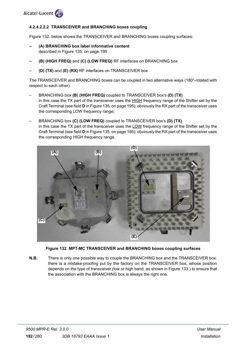
4.2.4.2.2.2 TRANSCEIVER and BRANCHING boxes coupling
Figure 132. below shows the TRANSCEIVER and BRANCHING boxes coupling surfaces:
– (A) BRANCHING box label informative contentdescribed in Figure 135. on page 195
– (B) (HIGH FREQ) and (C) (LOW FREQ) RF interfaces on BRANCHING box
– (D) (TX) and (E) (RX) RF interfaces on TRANSCEIVER box
The TRANSCEIVER and BRANCHING boxes can be coupled in two alternative ways (180°-rotated with respect to each other):
– BRANCHING box (B) (HIGH FREQ) coupled to TRANSCEIVER box’s (D) (TX)in this case the TX part of the transceiver uses the HIGH frequency range of the Shifter set by the Craft Terminal (see field D in Figure 135. on page 195); obviously the RX part of the transceiver uses the corresponding LOW frequency range;
– BRANCHING box (C) (LOW FREQ) coupled to TRANSCEIVER box’s (D) (TX)in this case the TX part of the transceiver uses the LOW frequency range of the Shifter set by the Craft Terminal (see field D in Figure 135. on page 195); obviously the RX part of the transceiver uses the corresponding HIGH frequency range.
(A) (B)
(C)
(D)
(E)
Figure 132. MPT-MC TRANSCEIVER and BRANCHING boxes coupling surfaces
N.B. There is only one possible way to couple the BRANCHING box and the TRANSCEIVER box: there is a mistake-proofing put by the factory on the TRANSCEIVER box, whose position depends on the type of transceiver (low or high band, as shown in Figure 133.) to ensure that the association with the BRANCHING box is always the right one.
User Manual
Installation
9500 MPR-E Rel. 3.0.0
3DB 18793 EAAA Issue 1192/280

Hole
Mistake-proofing
Figure 133. 7-8 GHz MPT-MC BRANCHING box mistake-proofing
User Manual
Installation
9500 MPR-E Rel. 3.0.0
3DB 18793 EAAA Issue 1 193/280

4.2.4.2.3 Labels affixed on the MPT-MC
a) The label depicted in Figure 134. below is affixed externally to all types of MPT-MC and MPT-MC TRANSCEIVER boxes;
b) Only for MPT-MC with external diplexers, an additional label, depicted in Figure 135. on page 195, is placed on the branching assembly.
SYMBOL OR WRITING MEANING
9500-MPR Equipment Acronym & Alcatel-Lucent Logo
CE European Community logo
! Not harmonized frequency logo
2002/96/EC WEEE (Waste Electrical and Elec-tronic Equipment) Logo
-28 V / -58 V 1,6 A / 0,8 A Power supply range and current range
Logistical Item (shown numbers as examples) Logistical Item for Customer
A Logistical Item for Customer, bar code 128
Serial n° (shown numbers as examples) Factory Serial number
B Factory Serial number bar code 128
TX Frequency MHz (shown numbers as examples) Working frequency range
Shifter MHz (shown numbers as examples) Shifter
TX Sub-band (shown numbers as examples) TX Sub-band
Initial SW/ICS (shown numbers as examples) P/N and ICS of the software loaded in factory
PN/ICS (shown numbers as examples) Factory P/N + ICS
C Factory P/N + ICS bar code 128
Figure 134. Label affixed on the MPT-MC and MPT-MC TRANSCEIVER box
User Manual
Installation
9500 MPR-E Rel. 3.0.0
3DB 18793 EAAA Issue 1194/280

N.B. In the label A9400 is written because the diplexers are also used in A9400 AWY.
SYMBOL OR WRITING MEANING
A9400 Equipment Acronym & Alcatel-Lucent Logo
CE European Community logo
12345 (example) Notified body
! Not harmonized frequency logo
2002/96/EC WEEE (Waste Electrical and Elec-tronic Equipment) Logo
PN/ICS 3DB 06775 AAAA 01 (example) Factory Technical Code + ICS
A Factory Technical Code + ICS, bar code 128
Logistical Item 3DB 06775 AAXX (example) Logistical Item for Customer
B Logistical Item for Customer, bar code 128
S/N CW 050609001 (example) Factory Serial number
C Factory Serial number bar code 128
D (shown numbers as examples) – the field “Shifter MHz” indicates the possible frequency bands that can be used with this branching assembly. The choice between different shifters is done byCraft Terminal;
– for each “Shifter MHz”, the TX “LOW” and “HIGH” rows indicate the frequency range assumed by transceiver TX section, accord-ing to the TRANSCEIVER and BRANCHING boxes coupling.
Figure 135. Label affixed inside the MPT-MC BRANCHING box
User Manual
Installation
9500 MPR-E Rel. 3.0.0
3DB 18793 EAAA Issue 1 195/280

4.2.4.3 How to change polarization in the MPT-MC
4.2.4.3.1 6 and 11-38 GHz MPT-MC
1 2
3
Remove the plastic protection cover from the MPT-MC.
Change the polarization of the MPT-MC, if required (default: vertical polarization).To rotate the polarization use the Allen wrench.
Horizontal polarization.
Protection cover
Unscrew the 2 screwsand rotate by 45°
Polarizationreference
Polarizationreference
The polarization must be changed to match the antenna polarization and the coupler nose waveguide.
Note
User Manual
Installation
9500 MPR-E Rel. 3.0.0
3DB 18793 EAAA Issue 1196/280

4.2.4.3.2 7-8 GHz MPT-MC
These MPT-MC have fixed polarization (vertical polarization). To change the polarization it is necessary to change the antenna polarization and to install the MPT-MC 90° rotated.
1 2Example of vertical polarization (left offset). Example of horizontal polarization (left offset).
3 4Example of vertical polarization (right offset).
Example of horizontal polarization (right offset).
4.2.4.4 Types of Pole Mounting Installation kits
Refer to paragraph 4.2.2.4 on page 148.
4.2.4.5 Types of nose adapters
Refer to paragraph 4.2.2.5 on page 149.
User Manual
Installation
9500 MPR-E Rel. 3.0.0
3DB 18793 EAAA Issue 1 197/280

4.2.4.6 1+0 MPT-MC installation (integrated antenna) - all frequencies
[1] Check/Set the coupling between the TRANSCEIVER and BRANCHING boxes (only for MPT-MC with external diplexer).
[2] Install the Antenna and Pole Mounting.This pole mounting is delivered as “pole mounting”, “antenna”, and frequency-specific “nose adapter” already assembled. The integrated antenna is mounted on the pole front.Antenna and pole mounting must be installed in accordance with the manufacturer’s instructions.
[3] Check or change the polarization on the Antenna nose.To change the polarization, follow the instructions supplied with each antenna. Figure below shows an example.
N.B. The antennas are normally supplied with vertical polarization.
Figure 136. Example of antenna polarization change (“1+0” MPT-MC integrated antenna)
[4] Take off the solar shield from the MPT-MC transceiver by unscrewing the screws placed on the solar shield back panel.
[5] Install the MPT-MC on the Antenna nose adapter.
N.B. Before inserting the MPT-MC on nose adapter, it is mandatory to put SILICONE grease on the O-ring.
User Manual
Installation
9500 MPR-E Rel. 3.0.0
3DB 18793 EAAA Issue 1198/280

Putting silicone grease
Figure 137. Putting silicone grease on O-ring before MPT-MC insertion
1) Grasp the MPT-MC module by the handle.
2) Open the four looking hooks (1) arranged on the four walls of the MPT-MC unit.
3) For 7-8 GHz MPT-MC only rotate the MPT-MC depending on the horizontal or vertical polar-ization, and slide it on the nose adapter.
4) Secure the MPT-MC module through the four hooks (1) on the relative brackets (2).
(1) Hook
(2) Bracket
Figure 138. MPT-MC 1+0 installation for integrated antenna (6 GHz and 11-38 GHz)
N.B. For 6 GHz and 11-38 GHz MPT-MC remember to set first the correct polarization.
User Manual
Installation
9500 MPR-E Rel. 3.0.0
3DB 18793 EAAA Issue 1 199/280

(1) Hook
(2) Bracket
Figure 139. MPT-MC 1+0 installation for integrated antenna (7-8 GHz: vertical polarization)
(1) Hook
(2) Bracket
Figure 140. MPT-MC 1+0 installation for integrated antenna (7-8 GHz: horizontal polarization)
REMINDER: The MPT-MC/antenna assembly requires no additional seal on the SHF flanges; the two ends are smooth. The O-ring seal around the male “nose” provides sealing.
[6] Ground the MPT-MC system.
[7] Pre-point the antenna.
[8] Reinstall the solar shield onto the MPT-MC transceiver by screwing on it the solar shield screws.
[9] Affix the EMF stickers.
User Manual
Installation
9500 MPR-E Rel. 3.0.0
3DB 18793 EAAA Issue 1200/280

4.2.4.7 1+0 MPT-MC installation (non integrated antenna) - all frequencies
[1] Check/Set the coupling between the TRANSCEIVER and BRANCHING boxes (only for MPT-MC with external diplexer).
[2] Install the Nose Adapter on the “Pole Mounting for Remote ODU”.
[3] Install the “Pole Mounting for Remote ODU”.Pole mounting must be installed in accordance with the manufacturer’s instructions.In case of missing instructions, fix the U-bolts with 34 N x m tightening torque.
N.B. The pole mounting can be installed on the Right or Left hand side of the pole depending on the azimuth and on the configuration of the tower.
Figure 141. "Pole Mounting for Remote ODU" installation
[4] Take off the solar shield from the MPT-MC transceiver by unscrewing the screws placed on the solar shield back panel.
[5] Install the MPT-MC.
N.B. Before inserting the MPT-MC on nose adapter, it is mandatory to put SILICONE grease on the O-ring.
Putting silicone grease
Figure 142. Putting silicone grease on O-ring before MPT-MC insertion
1) Grasp the MPT-MC module by the handle. Open the four looking hooks arranged on the four walls of the MPT-MC unit.
2) Position the Pole mounting support on the pole side as shown in the plant documentation.
User Manual
Installation
9500 MPR-E Rel. 3.0.0
3DB 18793 EAAA Issue 1 201/280

3) Position the MPT-MC and slide it on the nose adapter.
4) Secure the MPT-MC module through the four hooks onto the relative brackets.
Figure 143. MPT-MC 1+0 installation for not integrated antenna (with pole mounting P/N 3DB 10137 AAAB)
[6] Install the external Antenna with its own Pole Mounting.The installation of the antenna and of its own pole mounting, as well as the antenna polarization check/change, must be done in accordance with the manufacturer’s instructions.
[7] Connect the antenna side (flange) of the Pole Mounting’s nose adapter to the external antenna, by means of the “Flextwist“ waveguide.
[8] Ground the MPT-MC system.
[9] Pre-point the antenna.
[10] Reinstall the solar shield onto the MPT-MC transceiver by screwing on it the solar shield screws.
[11] Affix the EMF stickers.
User Manual
Installation
9500 MPR-E Rel. 3.0.0
3DB 18793 EAAA Issue 1202/280

4.2.4.8 How to terminate the Ethernet cable (MPT-MC side) and to pull up it from Indoor to MPT-MC
To terminate the cable the Short kit plug R2CT must be used.
The kit is made up of 10 items as shown in Figure 145.
Figure 144. Short kit plug R2CT
Figure 145. Short kit plug R2CT items
User Manual
Installation
9500 MPR-E Rel. 3.0.0
3DB 18793 EAAA Issue 1 203/280

4.2.4.8.1 Mating sequence instructions
To terminate and to connect the cable to the MPT-MC follow the instructions:
1 2Turn and remove the protection cap. Unscrew partially the nut spiral.
3 Pass the cable through the mini short kit plug and crimp the RJ45 plug according to the standardprocedure
4 5Insert the RJ45 plug inside the unlocking clip (keep attention to have the latches mechanisms on the same side )
Pull the cable and insert the unlocking clip together with the RJ45 plug inside the body,
the latches being aligned with the body bayonet pin. Place the body arm on the left side.
User Manual
Installation
9500 MPR-E Rel. 3.0.0
3DB 18793 EAAA Issue 1204/280

6 If you need to hoist the assembly, pull the coupling nut so as to cover the plug body and put back the protection cap on
9 10Align the two marks on the plug body and the receptacle, insert and rotate clockwise the plug body into the receptacle
Connect the RJ45 plug to its socket by pushing the cable.
7 Tighten the nut spiral with a 21 mm wrench with a torque of 3N.m mini and 3,5 maxi. The cable is now fixed with the plug and ready to be pulled.
8 Install the cable then unscrew partially the nut spiral and remove the protection cap to connect to the receptacle
User Manual
Installation
9500 MPR-E Rel. 3.0.0
3DB 18793 EAAA Issue 1 205/280

11 Secure the assembly by screwing the nut spiral with a 21mm wrench with a torque of 3 N.m mini and 3,5 N.m maxi
12Push and rotate clockwise the coupling nut until secured onto the receptacle
4.2.4.8.2 Unmating sequence instructions
1 2Unscrew the nut spiral via 21 mm adapted wrench.
Rotate and unlock the coupling nut.
3 Engage the RJ45 unlocking clip forward until front stop.
Press on the unlocking clip latch.4
User Manual
Installation
9500 MPR-E Rel. 3.0.0
3DB 18793 EAAA Issue 1206/280

5 6Pull the clip and the cable rearward to disconnect the RJ45 plug.
Rotate and disconnect the R2CT plug body.
4.2.4.9 Installing the “Flextwist“ waveguide (not integrated antenna cases)
Refer to paragraph 4.2.2.11 on page 168.
4.2.4.10 MPT-MC system grounding
Refer to paragraph 4.2.2.12 on page 170.
4.2.4.11 Cable Grounding
Refer to paragraph 4.2.2.13 on page 171.
User Manual
Installation
9500 MPR-E Rel. 3.0.0
3DB 18793 EAAA Issue 1 207/280

4.2.5 Power Extractor
With the Power Extractor, to be installed close to the MPT-HC, the interconnection between the Indoor and the MPT-HC can be made with a single electrical Ethernet cable by using the “Power Feed over Ether-net” solution (Ethernet traffic and Power Supply on the same cable) provided by the Power Injector. The Power Extractor then separates the Power Supply from the Ethernet traffic, which are separately sent to the MPT-HC.
The two cables, interconnecting the Power Extractor to the MPT-HC (the Power Supply cable to be con-nected to the DC Out connector of the Power Extractor and Ethernet cable to be connected to the Data Out connector of the Power Extractor), are provided, already terminated (2 m long), with the Power Extractor itself.
To prepare and to terminate the “Ethernet data + Power Supply” cable (to be connected to the Power Injec-tor and to the DC+Data In connector of the Power Extractor) follow the instructions given in para. 4.2.4.8on page 203.
The R2CT connector used to terminate the cable (Power Extractor side) is provided with the Power Extractor.
3 4Connect the 3 cables (2 cables to the MPT-HC and 1 cable to the Power Injector).
The final installation is shown in the figure.
1 Install the Power Extractor on the pole close to the MPT-HC.
Connect the Power Extractor to the ground by using the 6 mm2 grounding cable pro-vided with the Power Extractor.
2
User Manual
Installation
9500 MPR-E Rel. 3.0.0
3DB 18793 EAAA Issue 1208/280

4.2.6 Power Injector
4.2.6.1 Power Injector box
The installation in 19” rack is shown in the Figure 146.
The Power Injector box must be first installed on the bracket (3DB77008ACXX) by using the screws pro-vided with the bracket, and then the assembly must be installed on the rack.
N.B. On the bracket can be installed a second Power Injector box.
Figure 146. Power Injector box + Bracket 3DB77008ACXX
For the installation in 21” rack the 21” Adapter kit (3CC50065AAAA) must be added to each 19” installation configuration.
4.2.6.1.1 Power Injector box grounding
The assembly must be grounded by using the ground screw present on the bracket, as shown in Figure 147.
The section cable (wire) is 6 mm² (9AWG) (Yellow/Green).
Figure 147. Grounding
4.2.6.1.2 Power Supply Cable
Figure 148. Power supply connector
A 2-wire power cable (2x1 mm2 - AWG12) is supplied (1AC007800068).
The blue wire must be connected to -48 Vdc (live); the black wire to ground/+ve.
The cable must be screwed to the Power Injector box and to the battery.
User Manual
Installation
9500 MPR-E Rel. 3.0.0
3DB 18793 EAAA Issue 1 209/280

4.2.6.2 Power Injector plug-in
The Power Injector plug-in is installed inside the SAR.
Figure 149. Power Injector plug-in
User Manual
Installation
9500 MPR-E Rel. 3.0.0
3DB 18793 EAAA Issue 1210/280

4.2.7 Installation items
This section includes:
– Indoor accessories for MPT-HC and MPT-HC V2 (par. 4.2.7.1 on page 211)
– Accessories and cables for MPT-HC connections (par. 4.2.7.2 on page 211)
– Accessories and cables for MPT-HC V2 connections (par. 4.2.7.3 on page 213)
– Accessories and cables for MPT-MC connections (par. 4.2.7.4 on page 214)
– Nose Adapter for MPT-HC and MPT-MC (par. 4.2.7.5 on page 214)
– Flextwists for MPT-HC and MPT-MC (par. 4.2.7.6 on page 215)
– Ethernet Electrical Cables (par. 4.2.7.7 on page 215)
4.2.7.1 Indoor accessories for MPT-HC and MPT-HC V2
3CC52159AAXX Pigtail These accessories must be used to connect the power coaxial cable of MPT-HC and MPT-HC V2 to the bat-tery
1AB251350001 Low Pass Filter
3CC50030AAAA Lighting Arrestor
4.2.7.2 Accessories and cables for MPT-HC connections
1AC001100022 Coax cable 50 ohm (diam.=10.3 mm) for L>240 m
1AB095530023 Conn. male straigth 50 ohm (diam.=10.3 mm)
1AB128500002 Cable grounding kit (diam.=10.3 mm)
1AC041350001 Coax. cable 50 ohm (diam.=6.85 mm) for L<240 m
1AB095530036 N Conn. Male straigth 50 ohm for coax. cable (diam.=6.85 mm)
1AD040130004 Grounding kit for coax. cable (diam.=6.85 mm)
1AC016760006 IDU-ODU Ethernet cable Cat5e shield 80% for outdoor environment
1AB074610027 RJ45 connector (boot included)
1AD160490001 Tool for HIROSE RJ45 IDU-ODU cable assembling
1AD024450011 Gland, cable feed-through EMC (to be inserted in the electrical cable)
1AF17000AAAA Hoisting protection tube (for ethernet or fiber cord)
User Manual
Installation
9500 MPR-E Rel. 3.0.0
3DB 18793 EAAA Issue 1 211/280

1AD040130004 Grounding kit for RJ45 Ethernet electrical cable
3CC08166AAXX ODU Grounding kit
3CC52160ALAA LC-LC cord for MPT IDU_ODU connection80m pre-assembled fiber cable + gland
3CC52160AAAA LC-LC cord for MPT IDU_ODU connection100m pre-assembled fiber cable+ gland
3CC52160ABAA LC-LC cord for MPT IDU_ODU connection120m pre-assembled fiber cable+ gland
3CC52160ACAA LC-LC cord for MPT IDU_ODU connection140m pre-assembled fiber cable+ gland
3CC52160ADAA LC-LC cord for MPT IDU_ODU connection160m pre-assembled fiber cable+ gland
3CC52160AEAA LC-LC cord for MPT IDU_ODU connection180m pre-assembled fiber cable+ gland
3CC52160AFAA LC-LC cord for MPT IDU_ODU connection200m pre-assembled fiber cable+ gland
3CC52160AGAA LC-LC cord for MPT IDU_ODU connection220m pre-assembled fiber able+ gland
3CC52160AHAA LC-LC cord for MPT IDU_ODU connection250m pre-assembled fiber cable+ gland
3CC52160AIAA LC-LC cord for MPT IDU_ODU connection300m pre-assembled fiber cable+ gland
3CC50097AAXX Cable overlength box (wall and pipe mounting only)
1AD161130001 Dynamometric wrench for Gland 20mm (10N)
1AD161030001 Dynamometric wrench for ODC
1AB383760001 Optical SFP - MPR/MPT
3CC50098AAXX MPR-MPT tool bag (special tools)
3CC50099AAXX Standard tool bag
3CC50107AAXX Power Extractor (it includes the two 2 m jumpers for connection to MPT-HC, the R2CT connector to terminate the Power Injector-Power Extractor cable and the grounding kit)
User Manual
Installation
9500 MPR-E Rel. 3.0.0
3DB 18793 EAAA Issue 1212/280

4.2.7.3 Accessories and cables for MPT-HC V2 connections
3DB18205AAAA QMA (male)-N (Female) RF cable
3CC50074ABAA Support kit for 4 cord N/QMA MPR IDU
1AB357780003 QMA 90° connector for coax. cable (diam.=6.85 mm)
3CC52188AAXX 1 m Adapter cord (N female-Free wires) (plus RJ45-indoor) for the power sup-ply cable. To be used only if the optical cable is used for the Ethernet traffic.
3CC52188AAAA 1 m Adapter cord (N female-Free wires) (plus RJ45 plus R2CT-outdoor) for the power supply cable. To be used only if the optical cable is used for the Ethernet traffic.
1AC016760006 IDU-ODU Ethernet cable Cat5e shield 80% for outdoor environment (cable to be used with PFoE)
3CC08166AAXX ODU Grounding kit
1AC001100022 Coax cable 50 ohm (diam.=10.3 mm) for L>200 m
1AB095530023 N Conn. male straigth 50 ohm for coax. cable (diam.=10.3 mm)
1AB128500002 Grounding kit for coax. cable (diam.=10.3 mm)
1AC041350001 Coax. cable 50 ohm (diam.=6.85 mm) for L<200 m
1AB095530036 N Conn. male straigth 50 ohm for coax. cable (diam.=6.85 mm)
1AD040130004 Grounding kit for coax. cable (diam.=6.85 mm)
3CC52170AAAA Q-XCO to Q-XCO Fiber cord (L = 80 m for MPT IDU-ODU connection)
3CC52170ABAA Q-XCO to Q-XCO Fiber cord (L = 100 m for MPT IDU-ODU connection)
3CC52170ACAA Q-XCO to Q-XCO Fiber cord (L = 120 m for MPT IDU-ODU connection)
3CC52170ADAA Q-XCO to Q-XCO Fiber cord (L = 140 m for MPT IDU-ODU connection)
3CC52170AEAA Q-XCO to Q-XCO Fiber cord (L = 160 m for MPT IDU-ODU connection)
3CC52170AFAA Q-XCO to Q-XCO Fiber cord (L = 180 m for MPT IDU-ODU connection)
3CC52170AGAA Q-XCO to Q-XCO Fiber cord (L = 200 m for MPT IDU-ODU connection)
3CC52170AHAA Q-XCO to Q-XCO Fiber cord (L = 220 m for MPT IDU-ODU connection)
User Manual
Installation
9500 MPR-E Rel. 3.0.0
3DB 18793 EAAA Issue 1 213/280

4.2.7.4 Accessories and cables for MPT-MC connections
1AC016760006 IDU-ODU Ethernet cable Cat5e shield 80% for outdoor environment
1AB074610027 RJ45 connector (cable diam <=7mm) (boot included)
1AD160490001 Tool for HIROSE RJ45 IDU-ODU cable assembling
1AB150990002 Short kit plug R2CT
1AF17000AAAA Hoisting protection tube (for ethernet or fiber cord)
1AD040130004 Grounding kit for RJ45 Ethernet electrical cable
3CC08166AAXX ODU Grounding kit
3CC50098AAXX MPR-MPT tool bag (special tools)
3CC50099AAXX Standard tool bag
4.2.7.5 Nose Adapter for MPT-HC and MPT-MC
3DB01460AAXX 6 GHz Nose Adapter (for Not Integrated Antenna)
3DB01459AAXX 7/8 GHz Nose Adapter (for Not Integrated Antenna)
3CC50125AAXX 11 GHz Nose Adapter (for Not Integrated Antenna)
1AB146090003 13 GHz Nose Adapter (for Not Integrated Antenna)
1AB146090001 15 GHz Nose Adapter (for Not Integrated Antenna)
1AB146090002 18/23/25 Nose Adapter (for Not Integrated Antenna)
3DB02082AAXX 28/38 Nose Adapter (for Not Integrated Antenna)
3CC52170AIAA Q-XCO to Q-XCO Fiber cord (L = 250 m for MPT IDU-ODU connection)
3CC52170ALAA Q-XCO to Q-XCO Fiber cord (L = 300 m for MPT IDU-ODU connection)
3CC50097AAAA Cable overlength box (wall and pipe mounting only)
User Manual
Installation
9500 MPR-E Rel. 3.0.0
3DB 18793 EAAA Issue 1214/280
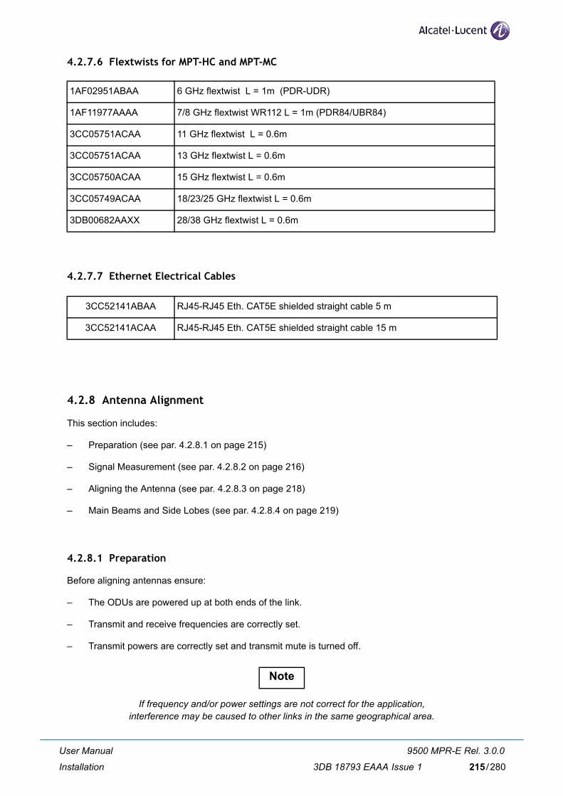
4.2.7.6 Flextwists for MPT-HC and MPT-MC
1AF02951ABAA 6 GHz flextwist L = 1m (PDR-UDR)
1AF11977AAAA 7/8 GHz flextwist WR112 L = 1m (PDR84/UBR84)
3CC05751ACAA 11 GHz flextwist L = 0.6m
3CC05751ACAA 13 GHz flextwist L = 0.6m
3CC05750ACAA 15 GHz flextwist L = 0.6m
3CC05749ACAA 18/23/25 GHz flextwist L = 0.6m
3DB00682AAXX 28/38 GHz flextwist L = 0.6m
4.2.7.7 Ethernet Electrical Cables
3CC52141ABAA RJ45-RJ45 Eth. CAT5E shielded straight cable 5 m
3CC52141ACAA RJ45-RJ45 Eth. CAT5E shielded straight cable 15 m
4.2.8 Antenna Alignment
This section includes:
– Preparation (see par. 4.2.8.1 on page 215)
– Signal Measurement (see par. 4.2.8.2 on page 216)
– Aligning the Antenna (see par. 4.2.8.3 on page 218)
– Main Beams and Side Lobes (see par. 4.2.8.4 on page 219)
4.2.8.1 Preparation
Before aligning antennas ensure:
– The ODUs are powered up at both ends of the link.
– Transmit and receive frequencies are correctly set.
– Transmit powers are correctly set and transmit mute is turned off.
If frequency and/or power settings are not correct for the application, interference may be caused to other links in the same geographical area.
Note
User Manual
Installation
9500 MPR-E Rel. 3.0.0
3DB 18793 EAAA Issue 1 215/280

4.2.8.2 Signal Measurement
Two receive signal-strength indicators are provided to assist antenna alignment, RSL in the WebEML screen, and the RSSI voltage at LEMO connector on the MPT-HC. Refer to:
– Using RSL Data (see par. 4.2.8.2.1 on page 216)
– Using the RSSI Voltage at the MPT-HC (see par. 4.2.8.2.2 on page 216)
– RSL Measurement Guidelines (see par. 4.2.8.2.2.1 on page 217)
4.2.8.2.1 Using RSL Data
As CT is accessed via connection to the GEthernet Generic Device, a separate means of communication such as two-way radio or cell phone is required between the WebEML operator and the person at the antenna.
To align using RSL:
1) Monitor RSL in the WebEML screen.
2) Set antenna alignment for maximum RSL.
3) Repeat for the far end of the link.
4) Compare actual RSLs with the expected RSLs from the link installation datapack. RSL mea-surement accuracies:
a) ± 2 dB for levels -40 to -70 dBm, over a temperature range of 0 to +35°C.
b) ±4 dB for levels -25 to -85 dBm, over an extended -33 to +55°C range.
4.2.8.2.2 Using the RSSI Voltage at the MPT-HC/MPT-MC
A voltmeter, such as a multimeter, is used to measure RSSI voltage.
Use the MPT/AWY Service Cord for the power monitoring in addition to a voltmeter.
1) Connect a voltmeter to the MPT-HC/MPT-MC through the MPT/AWY Service Cord.
2) Adjust antenna alignment until the voltage reading is at maximum value.
3) Repeat for the far end of the link.
Check and record the peak voltage at each end. The RSSI voltage provides a direct relationship with RSL, as follows:
Units Measurement (with MPT-HC/MPT-MC)
Service kit cable (Vdc) 5 4.71 4.12 3.5 2.9 2.3 1.71 1.11 0.59 0.14
RSL (dBm) -10 -20 -30 -40 -50 -60 -70 -80 -90 -100
4) Compare actual RSLs to the expected RSLs from the link installation datapack. Refer to par. 4.2.8.2.2.1 - RSL Measurement Guidelines.
User Manual
Installation
9500 MPR-E Rel. 3.0.0
3DB 18793 EAAA Issue 1216/280

MPT/AWY Service Cord operative information
Figure 150. herebelow shows the optional cable P/N 3CC52191AAXX to be used during the commis-sioning to point the antenna and connect the MCT directly to the MPT (if required).
LEMO wire 6 = ground
Connection table
Signal M1 M2 M3 M4
ETH_TXP_T 1 3
ETH_TXN_T 2 6
GND 3 X
ETH_RXP_T 4 1
ETH_RXN_T 5 2
PRX_OUT 12 X
Figure 150. MPT/AWY Service Cord
Connector usage:
– (M1) LEMO connector, to be plugged into LEMO connector on MPT-HC/MPT-HC V2/MPT-MC.
– banana plugs (M3) and (M4): output is a 0 to +5V DC voltage proportional to the radio Rx field. Duringequipment line–up, through a multi–meter it is possible to easily point the antenna until the measuredvoltage is the maximum, corresponding to the maximum radio Rx field.
– (M2) RJ45 connector, to connect the WebEML directly to the MPT.
4.2.8.2.2.1 RSL Measurement Guidelines
RSSI/RSL Accuracy
When checking RSSI/RSL against the predicted link values ensure appropriate allowances are made for Tx power-setting accuracy, path-loss calculation accuracy, and RSSI/RSL measurement accuracy.
– For a worst-case the overall accuracy is the sum of the individual accuracy limits, which for a link would be ±4 dB of the predicted value (±2 dB for transmit, ±2 dB for receive, 0 to 35°C), aside from the path-loss calculation accuracy, which should be within limits of ±3 dB.
– Typically, where the measured RSSI/RSL is more than 4 dB lower than the expected receive level you should check the path survey results, path calculations and antenna alignment.
User Manual
Installation
9500 MPR-E Rel. 3.0.0
3DB 18793 EAAA Issue 1 217/280

When checking RSSI/RSL ensure the measurement is made under normal, unfaded and interference-free path conditions.
– A discrepancy of 20 dB or greater between the measured and calculated RSSI/ RSLs suggests an antenna is aligned on a side lobe, or there is a polarization mismatch.
4.2.8.3 Aligning the Antenna
Antenna alignment involves adjusting the direction of each antenna until the received signal strength reaches its maximum level at each end of the link.Fine adjustment for azimuth (horizontal angle) and elevation (vertical angle) is built into each antenna mount.Adjustment procedures will be provided with each antenna.If the horizontal adjuster does not provide suf-ficient range to locate the main beam, the antenna mounting brackets will need to be loosened and the antenna swiveled on its pole mount to locate the beam.Before doing this ensure the horizontal adjuster is set for mid-travel.Some mounts for larger antennas have a separately clamped swivel base to allow the loosened antenna to swivel on it without fear of slippage down the pole. Where such a mount is not provided a temporary swivel clamp can often be provided using a pair of pipe brackets bolted together immediately below the antenna mount.
Ensure antennas are aligned on the main beam, and not a side lobe. For guidance, refer to the sections Locating the Main Beam (see par. 4.2.8.4.1 on page 219)
and Tracking Path Error (see par. 4.2.8.4.2 on page 220). Ensure ATPC is turned off during the alignment procedure.
4.2.8.3.1 Standard Alignment Procedure
To align an antenna:
1) Loosen the azimuth adjuster on the antenna mount (horizontal angle) and adjust azimuth posi-tion for maximum signal strength.
2) Tighten the azimuth securing mechanism. Ensure signal strength does not drop as it is tight-ened.
3) Loosen the elevation adjuster (vertical angle) and adjust for maximum signal strength.
4) Tighten the elevation securing mechanism. Ensure signal strength does not drop as it is tight-ened. The terminal is now aligned and ready to carry operational traffic.
5) Record RSL and/or RSSI voltage in the commissioning log.
Note
Note
User Manual
Installation
9500 MPR-E Rel. 3.0.0
3DB 18793 EAAA Issue 1218/280

4.2.8.4 Main Beams and Side Lobes
This section describes how to locate the main beam, and typical tracking path errors.
4.2.8.4.1 Locating the Main Beam
Ensure the antennas are aligned on the main beam, and not a side lobe.
Once a measurable signal is observed, very small alignment adjustments are required to locate the main beam. For instance, a 1.2m antenna at 23 GHz typically has 0.9° of adjustment from center of main beam to the first null (0.4° to the -3 dB point). Antenna movement across the main beam will result in a rapid rise and fall of signal level. As a guide, 1 degree of beam width is equivalent to moving approximately 1.0 mm around a standard 114 mm (4.5 in.) diameter O/D pipe.
Antennas can be verified as being on main beam (as opposed to a side lobe) by comparing measured receive signal level with the calculated level.
Signal strength readings are usually measurable when at least a main beam at one end and first side lobes at the other are aligned.
The strongest signal occurs at the center of the main beam. The highest first lobe signal is typically 20 - 25 dB less than the main beam signal. When both antennas are aligned for maximum main beam signal strength, the receive signal level should be within 2 dB of the calculated level for the path. This calculated level should be included in the installation datapack for the link.
Figure 151. is an example of a head-on, conceptual view of the beam signal strength, with concentric rings of side lobe peaks and troughs radiating outward from the main beam.
Figure 151. Indicative head-on signal pattern for a parabolic antenna
User Manual
Installation
9500 MPR-E Rel. 3.0.0
3DB 18793 EAAA Issue 1 219/280

4.2.8.4.2 Tracking Path Error
Side lobe signal readings can be confused with main beam readings. This is particularly true for the first side lobe as the signal level at its center is greater than the signal level at the edges of the main beam, and if tracking on an incorrect elevation (or azimuth) a false impression of main beam reception can be obtained. This illustration shows an example of this with a simplified head-on view of an antenna radiation pattern, and tracking paths for three elevation settings.
Figure 152. Example Tracking Path Signals
Line AA represents the azimuth tracking path of a properly aligned antenna.The main beam is at point 2, and the first side lobes at points 1 and 3. Line BB represents the azimuth tracking path with the antenna tilted down slightly. Signal strength readings show only the first side lobe peaks, 4 and 5. In some instances the side lobe peaks are unequal due to antenna characteristics, which can lead to the larger peak being mistaken for the main beam. The correct method for locating the main beam in this case is to set the azimuth position midway between the first side lobe peaks, and then adjust the elevation for maximum signal.
Line CC represents an azimuth tracking path with the antenna tilted down further still. The first side lobe signal peaks (6 and 7) appear as one peak, leading to a mistaken interpretation of a main beam. The correct method for locating the main beam is to set the azimuth at mid peak, between 6 and 7, and then adjust elevation for maximum signal.
This first side lobe peaking is probably the most frequent cause of misalignment in both azimuth and elevation, especially so if one side lobe peaks higher than the other, as shown in Figure 153. A common error is to move the antenna left to right along line DD, or top to bottom along line EE, always ending up with the maximum signal at position 1.
Figure 153. Example Tracking Path Signals on the First Side Lobe
User Manual
Installation
9500 MPR-E Rel. 3.0.0
3DB 18793 EAAA Issue 1220/280

4.3 Software local copy
This section explains how to prepare the TCO Suite and Craft Terminal environment in your PC.
– Getting Started (par. 4.3.1 on page 222)
– PC Characteristics (par. 4.3.2 on page 222)
– Local copy of the Software Package (SWP) to the PC (par. 4.3.3 on page 223)
– Local copy of the WebEML to PC (par. 4.3.4 on page 224)
– Configure the PC Network Card for the connection to the NE (par. 4.3.5 on page 229)
User Manual
Installation
9500 MPR-E Rel. 3.0.0
3DB 18793 EAAA Issue 1 221/280

4.3.1 Getting Started
Read the following before starting.
– The operator must be familiar with the use of personal computers in WINDOWS environment, internally from which the NE application software operates.
– TCO Software Suite is on one CD. Software Package (SWP) is on another CD. Verify versions of the CD-ROM.
– To properly install TCO Software Suite, a PC is required, having the characteristics specified in paragraph 4.3.2.
4.3.2 PC Characteristics
The PC to use for WebEML application must meet following characteristics:
PC Hardware Configuration:
– CPU: AMD Atlhon/Intel Celeron/Intel Pentium 4 or higher
– RAM: 1 GB
– Hard Disk space: 1.5 GB (available space for log files, JRE excluded)
– Display Resolution: 1280x800 pixel
– DVD-ROM Drive: needed for the TCO Suite
– Ethernet Interface: Ethernet Card 10/100 Mbps
– VLAN tagging capability (if PC used on MPT traffic port for provisioning or line-up)
Operating Systems Supported:
– Microsoft Windows XP Professional service pack 3 or Microsoft Windows Vista Ultimate service pack 2 or Windows 7
N.B. "Classic windows" setting must be choosen with Windows Vista and Windows 7.
Additional requirements:
– Microsoft Internet Explorer 6 SP1, 7, 8, Mozilla Firefox 2, 3, 3.5
– The Administrator password is needed only for Java installation.
– When Java has been installed, the standard user can run the TCO Suite
– Java Runtime Environment (JRE) 6 Update 14
An FTP Server must be installed on the PC with read right & write right, and the Windows Firewall must be desactivated.
Note
Warning
User Manual
Installation
9500 MPR-E Rel. 3.0.0
3DB 18793 EAAA Issue 1222/280

4.3.3 Local copy of the Software Package (SWP) to the PC
Follow these steps to copy the Software Package (SWP) to the PC.
[1] Insert the SWP CD into the CD-ROM drive.
The Software Package will auto-run and open up the computer's default browser program (if auto-run fea-ture is enabled on user's PC) as soon as the CD-ROM is read by the PC. If auto-run does not start, the user must run (double-click with left mouse button on it) the aluopener.exe file, available on CD-ROM root,
in order to launch the Software Package.
This certificate is not signed by a public/trusted certification authority. The Warning Security dialog will inform the user about this problem and browser/JRE will probably recognize the signature as "not valid". This is neither an error nor a problem. If the dialog message specifies that the signature cannot be ver-ified, it means the signed applet is correct but that the signature cannot be publicly checked on the Internet. As usual, both language and graphical layout could vary with respect to browser, operating system ver-sion, operating system and browser languages and so on. To avoid further requests it is suggested to con-
firm and "always trust" the stated certificate source.
[2] Click on the Local Copy button to copy the software to your local PC.
[3] Click on the Start Copying button.
[4] Choose a directory location for the Local Copy of Software Package. Select the directory and click on OK to begin the copy process.
Warning: Special characters (like #...) cannot be used.
[5] The files will be copied from the CD to the PC and will create a directory named ECT.
[6] A successful copy message will display, when all files have been copied. Click OK.
[7] Remove the SWP CD from the CD-ROM drive.
Note
Note
User Manual
Installation
9500 MPR-E Rel. 3.0.0
3DB 18793 EAAA Issue 1 223/280

4.3.4 Local copy of the WebEML to PC
Follow these steps to copy the WebEML to the PC.
[1] Insert the TCO Suite Rel 4.3 CD into the DVD-ROM drive.
The TCO Suite Rel 4.3 software will auto-run and open up the computer's default browser program (if auto-run feature is enabled on user's PC) as soon as the CD-ROM is read by the PC. If auto-run does not start, user must run (double-click with left mouse button on it) the Start.exe file, available on CD-ROM root, in order to launch the Software Package.
This certificate is not signed by a public/trusted certification authority. The Warning Security dialog will inform the user about this problem and browser/JRE will probably recognize the signature as "not valid". This is neither an error nor a problem. If the dialog message specifies that the signature cannot be verified, it means the signed applet is correct, but that the signature cannot be publicly checked on the Internet. As usual, both language and graphical layout could vary with respect to browser, operating system version, operating system and browser languages and so on. To avoid further requests it is suggested to confirm and "always trust" the stated certificate source.
[2] The following screen opens.
Note
Note
User Manual
Installation
9500 MPR-E Rel. 3.0.0
3DB 18793 EAAA Issue 1224/280
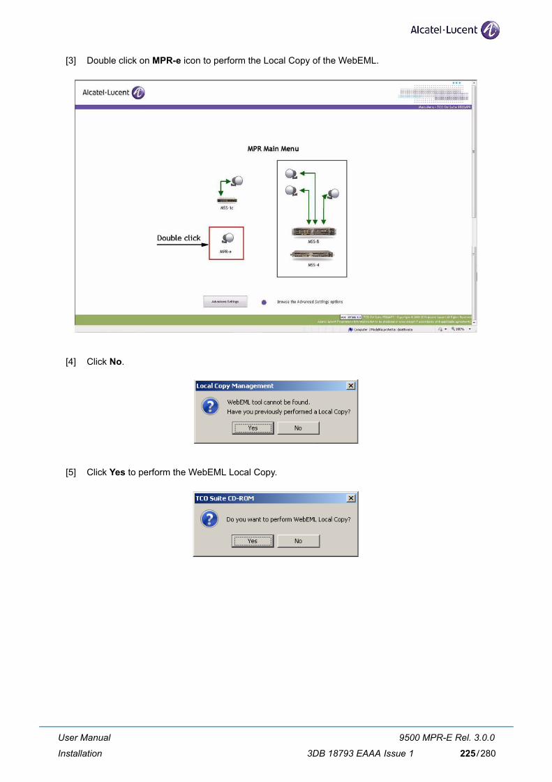
[3] Double click on MPR-e icon to perform the Local Copy of the WebEML.
[4] Click No.
[5] Click Yes to perform the WebEML Local Copy.
User Manual
Installation
9500 MPR-E Rel. 3.0.0
3DB 18793 EAAA Issue 1 225/280
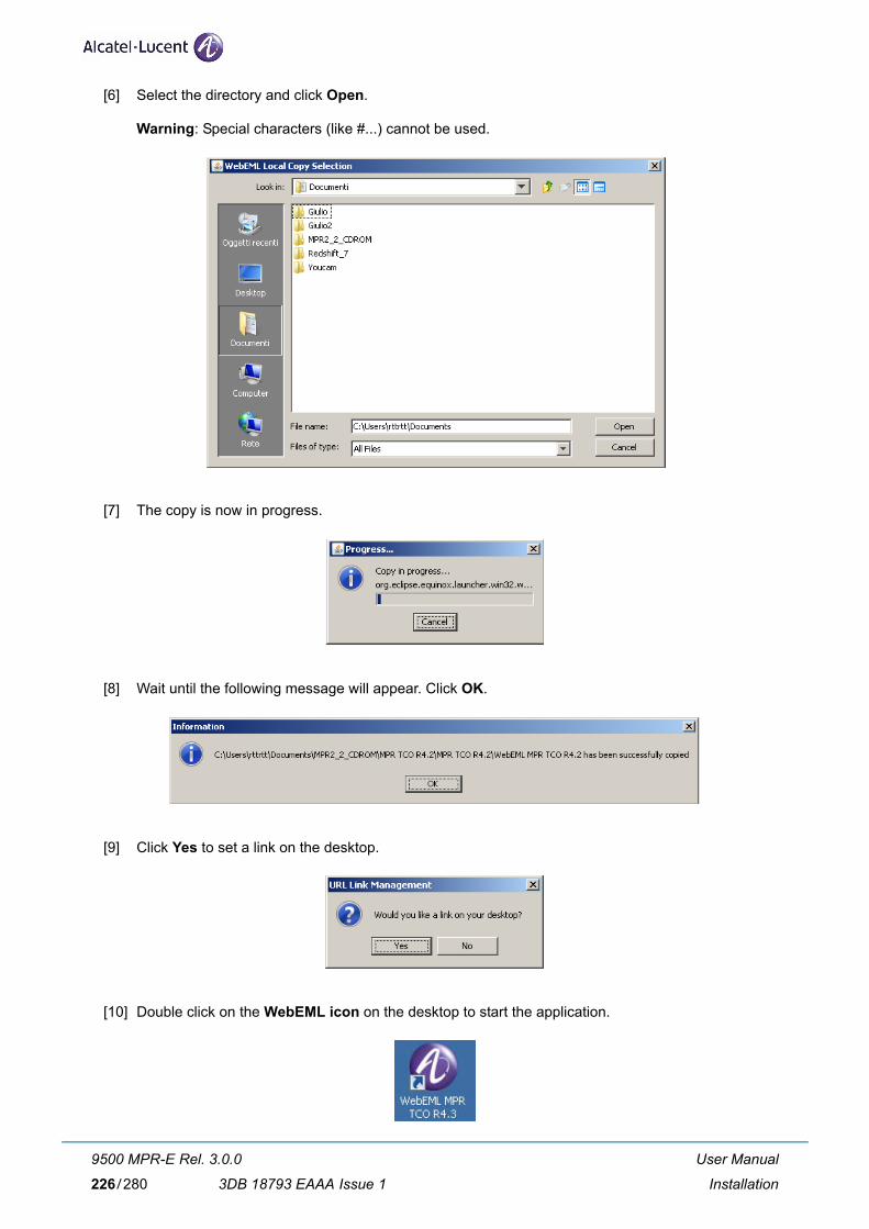
[6] Select the directory and click Open.
Warning: Special characters (like #...) cannot be used.
[7] The copy is now in progress.
[8] Wait until the following message will appear. Click OK.
[9] Click Yes to set a link on the desktop.
[10] Double click on the WebEML icon on the desktop to start the application.
User Manual
Installation
9500 MPR-E Rel. 3.0.0
3DB 18793 EAAA Issue 1226/280
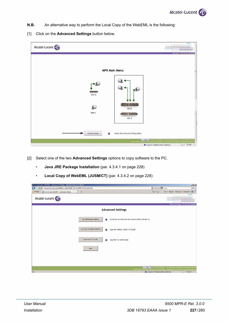
N.B. An alternative way to perform the Local Copy of the WebEML is the following:
[1] Click on the Advanced Settings button below.
[2] Select one of the two Advanced Settings options to copy software to the PC.
• Java JRE Package Installation (par. 4.3.4.1 on page 228)
• Local Copy of WebEML (JUSM/CT) (par. 4.3.4.2 on page 228)
User Manual
Installation
9500 MPR-E Rel. 3.0.0
3DB 18793 EAAA Issue 1 227/280

4.3.4.1 Java JRE Package Installation
[1] Click on the Java JRE Package Installation button to install the Sun Java Runtime Environment (JRE) 6 Update 14 version to your PC.
4.3.4.2 Local Copy of WebEML (JUSM/CT)
[1] Click on the Local Copy of WebEML (JUSM/CT) button to copy the WebEML software to your PC. Choose the directory location and click Open and then OK.
[2] When the files have finished copying, this window will display. Click the OK button.
[3] Click Yes to set a link on the desktop.
[4] An icon will be created on the desktop.
User Manual
Installation
9500 MPR-E Rel. 3.0.0
3DB 18793 EAAA Issue 1228/280

4.3.5 Configure the PC Network Card for the connection to the NE
Two options are available:
– Option 1: PC connected to the traffic port of MPT (par. 4.3.5.1 on page 229)
– Option 2: PC connected to GEthernet Generic device (par. 4.3.5.2 on page 232)
4.3.5.1 Option 1: PC connected to the traffic port of MPT
This example uses a Microsoft Windows 7 Professional system and refers to the first installation (default values), when the MPT has never been configured.
[1] Connect a CAT 5/5E cable from the MPT to the PC network card.
[2] Open up the NETWORK CONNECTIONS. Highlight the network card as shown below.
[3] PC configuration Enable VLAN management.
User Manual
Installation
9500 MPR-E Rel. 3.0.0
3DB 18793 EAAA Issue 1 229/280

[4] PC configuration: Network Address.
User Manual
Installation
9500 MPR-E Rel. 3.0.0
3DB 18793 EAAA Issue 1230/280

The default IP address for TMN in Band is 192.168.100.1
The PC must be in the same sub network.
User Manual
Installation
9500 MPR-E Rel. 3.0.0
3DB 18793 EAAA Issue 1 231/280

4.3.5.2 Option 2: PC connected to GEthernet Generic device
This example uses a Microsoft Windows XP Professional system and refers to the first installation (default values), when the MPT has never been configured.
[1] Connect a CAT 5/5E cable from the PC network card to the FE port of the GEthernet Generic Device.
[2] Click on the START menu on the Windows desktop and open up the CONTROL PANEL.
[3] Open up the NETWORK CONNECTIONS. Highlight the network card as shown below.
[4] Dobule click on Properties to display the screen below and scroll down the list to highlight the Inter-net Protocol (TCP/IP) line. Click the OK button.
User Manual
Installation
9500 MPR-E Rel. 3.0.0
3DB 18793 EAAA Issue 1232/280

[5] Enter, as example, the IP address 192.168.100.2 (subnet mask: 255.255.255.0) for the PC network card as shown below. Click OK.
The NE default IP address is 192.168.100.1 (mask 255.255.255.0); for this reason the PC IP address must belong to the same mask.
It is suggested to keep enabled only one network connection on a PC.
Note
Note
User Manual
Installation
9500 MPR-E Rel. 3.0.0
3DB 18793 EAAA Issue 1 233/280

[6] To check the connectivity between the PC and the NE, open up a DOS window or Command Prompt. Click on the START menu on the Windows desktop and open up the RUN window as shown below.
[7] Type cmd and click OK to open up a DOS window.
[8] The DOS window will display.
[9] In the DOS window, click the cursor after the > and type ping 192.168.100.1 to verify a connection between the PC and the NE. The Ping statistics for the IP address 192.168.100.1 should display 4 packets sent and and 4 packets received.
The 192.168.100.1 IP address is the default NE In-band IP address.
Note
User Manual
Installation
9500 MPR-E Rel. 3.0.0
3DB 18793 EAAA Issue 1234/280

User Manual
Installation
9500 MPR-E Rel. 3.0.0
3DB 18793 EAAA Issue 1 235/280

4.3.5.3 Possible error messages
NETO Launching: Error message
Action > Verify IP connectivity with ping
Action > Only one MCT session can be open on a MPR-e. Verify that no PC is already connected on the NE
User Manual
Installation
9500 MPR-E Rel. 3.0.0
3DB 18793 EAAA Issue 1236/280

MCT: Error message
Action > Verify IP connectivity with ping
User Manual
Installation
9500 MPR-E Rel. 3.0.0
3DB 18793 EAAA Issue 1 237/280

User Manual
Installation
9500 MPR-E Rel. 3.0.0
3DB 18793 EAAA Issue 1238/280

5 ProvisioningThis chapter describes the first installation procedures to configure the NE.
Since MPR-e is a stand alone equipment, for its provisioning there are 2 possible options:
– Option 1: MPT will be FIRST configured through the PC and AFTER connected to the GEthernet generic device (par. 5.1 on page 240)
– Option 2: MPT will be directly configured through the GEthernet generic device (par. 5.2 on page 245)
Here is an overview of the options detailled in this chapter.
Table 31. Provisioning option
Provisioningthrough
GEthernet Generic Device
connectivity
MPT-HC MPT-MC MPT-HC V2
Option 1(PC)
Option BOptical
Provisioning must be performed before HW installation of MPT
-Provisioning must be performed before HW installation of MPT
Option AElectrical
MPT can always be installed on pole mounting before provisioning
MPT can always be installed on pole mounting before provisioning
MPT can always be installed on pole mounting before provisioning
Option 2(GEthernet
GenericDevice)
Option BOptical MPT can always be
installed on pole mounting before provisioning
-MPT can always be installed on pole mounting before provisioning
Option AElectrical
MPT can always be installed on pole mounting before provisioning
User Manual
Provisioning
9500 MPR-E Rel. 3.0.0
3DB 18793 EAAA Issue 1 239/280

5.1 Option1: MPR-e will be configured through the PC
5.1.1 Pre requisites for the PC
– Ethernet 100Mbps (min) interface
– VLAN management capability
– For the configuration please refer to paragraph 4.3.5 on page 229.
5.1.2 MPT interconnection option
In paragraph 4.1 on page 129 are described the possible options for hardware installation after the first step of provisioning of the equipment.
– MPT-HC can be connected to the GEthernet generic device through optical or electrical connection.
– MPT-HC V2 can be connected to the GEthernet generic device through optical or electrical connec-tion.
– MPT-MC can only be connected through electrical connection.
Here below the summary table.
Table 32. Sumary table
MPT-HC MPT-HC V2 MPT-MC
OpticalDC Coaxial cable Coaxial cable
-Data Fiber cable Fiber cable
ElectricalDC Coaxial cable
CAT5e cable (PFoE) CAT5e cable (PFoE)Data CAT5e cable
5.1.2.1 Option A: MPT is interconnected to the GEthernet generic device in electrical
MPT can always be installed on the pole mounting before provisioning.
5.1.2.2 Option B : MPT is interconnected to the GEthernet generic device in optical
The configuration will not be possible from PC through SFP optical port (no PC are equipped), as con-sequence the provisioning must be performed through electrical interface BEFORE to install the MPT on the pole mounting with its final optical connectors.
User Manual
Provisioning
9500 MPR-E Rel. 3.0.0
3DB 18793 EAAA Issue 1240/280

5.1.3 Procedure
[1] Set up the interconnections to MPT in electrical:
• MPT-MC/MPT-HC V2 interconnection:
Note: MPT-MC/MPT-HC V2 can be installed on the pole-mounting.
• MPT-HC interconnection:
(Refer to par. 4.1.1)
Note: if MPT-HC final installation will be in optical on the pole mounting don't insert SFP module in the MPT and use a simple Ethernet cable connected to the RJ45 port for provisioning phase.
[2] Verify on the PC, that the MCT application has been installed (if not, refer to paragraph 4.3.4 on page 224 to install it).
[3] Configure the PC network card interface. See paragraph 4.3.5 on page 229.
[4] Launch directly the MCT by double clicking on file Mct.exe, located under the path created by the operator during the local copy and under\\WebEML MPR TCO R4.3\9500MCT_V01.02.XX\Mct.
User Manual
Provisioning
9500 MPR-E Rel. 3.0.0
3DB 18793 EAAA Issue 1 241/280
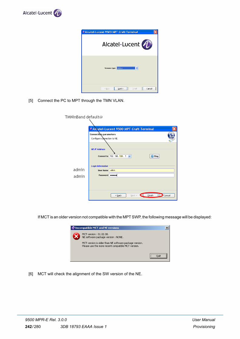
[5] Connect the PC to MPT through the TMN VLAN.
If MCT is an older version not compatible with the MPT SWP, the following message will be displayed:
[6] MCT will check the alignment of the SW version of the NE.
User Manual
Provisioning
9500 MPR-E Rel. 3.0.0
3DB 18793 EAAA Issue 1242/280

[7] If NE software must be upgraded, press Upgrade NE button.
[8] The following screen opens.
[9] Configure FTP server parameters.
[10] Select the descriptor file at the path : //ECT/SWDW/R95MPRE/1_1_0/R95SA.DSC
[11] Start Software Download.
[12] Activate the Standby Software Package.
[13] The MPT resets and the connection with MCT is lost.
[14] Re-open MCT as per point [4]).
User Manual
Provisioning
9500 MPR-E Rel. 3.0.0
3DB 18793 EAAA Issue 1 243/280

[15] Configure all the MPT parameters in menu Commissioning > Configuration (refer to paragraph 3.6.1.3 on page 92).
[16] MPT is now ready for MPR-e application. Disconnect MPT from PC and connect to GEthernet generic device.
User Manual
Provisioning
9500 MPR-E Rel. 3.0.0
3DB 18793 EAAA Issue 1244/280

5.2 Option 2: MPR-e will be configured directly through GEthernet generic device
5.2.1 Pre requisites for the GEthernet generic device
See paragraph 2.1.3 on page 36.
Note: in this situation MPT can always be installed on the pole mounting before provisioning.
5.2.2 Procedure
[1] Set up the interconnections as shown in Figure 85, Figure 86 for MPT-MC and in Figure 87, Figure 88 and Figure 89 for MPT-HC.
[2] Verify on the PC, that the MCT application has been installed (if not, refer to paragraph 4.3.4 on page 224 to install it).
[3] Configure PC network card interface. See paragraph 4.3.5 on page 229.
[4] Launch directly the MCT by double clicking on file Mct.exe, located under the path created by the operator during the local copy and under\\WebEML MPR TCO R4.3\9500MCT_V01.02.XX\Mct
See point [4] to point [8] of paragraph 5.1.3 on page 241.
[5] Re-open MCT as per point [4].
[6] Configure all the MPT parameters in menu Commissioning > Configuration (refer to paragraph 3.6.1.3 on page 92).
User Manual
Provisioning
9500 MPR-E Rel. 3.0.0
3DB 18793 EAAA Issue 1 245/280

[7] MPT is now ready for MPR-e application.
User Manual
Provisioning
9500 MPR-E Rel. 3.0.0
3DB 18793 EAAA Issue 1246/280

6 Maintenance and Trouble-clearing
6.1 Introduction
This section contains information and procedures to aid in restoring the equipment to its proper operating condition after it has been determined that a problem exists.
The following warnings and cautions apply while operating, performance testing, troubleshooting, or repairing the 9500 MPR-E series radios.
Short circuits in low-voltage, low-impedance dc circuits can cause severe arcing that may result in burns or eye injury. Remove rings,
watches, and other metal jewelry while working with primary circuits. Exercise caution to avoid shorting power input terminals.
Units with the electrostatic-sensitive (ESS) symbol contain ESS devices. Store these units in an antistatic container when not in use, and anyone handling a unit should observe antistatic precautions.
Refer to the Special Precautions pages in the front of the instruction book for detailed handling information.
Ensure that all antennas are properly aligned and waveguide is in good physical condition.
Before performing procedures that might in any way affect transmission, it is recommended that the person performing the procedure
understand the Rules and Regulations pertaining to the equipment and be properly authorized to operate the equipment.
Note
Note
User Manual
Maintenance and Trouble-clearing
9500 MPR-E Rel. 3.0.0
3DB 18793 EAAA Issue 1 247/280

6.2 Maintenance Philosophy
This section provides information and procedures for equipment maintenance down to the Card level. Card repair is not covered in this manual.
The use of maintenance procedures in this section may result from failure of a periodic check, an alarm indication, or unacceptable performance.
6.3 Personal Computer (PC)/Laptop
Connect the PC to the FE port of the GEthernet Generic Device.
6.4 Troubleshooting
This section provides guidance on:
– Before Going to Site Checklist
– Troubleshooting Basics
– Troubleshooting Path Problems
6.4.1 Before Going to Site Checklist
Where possible, before going to site obtain the following information:
– Does the fault require immediate attention?
– Determine who is the best-placed person to attend the fault.
– Confirm the nature and severity of the reported fault, its location, MPT type, frequency band, high/low end MPT, capacity modulation and configuration. Ask:
• Is just one link affected, or a number of links in the same geographical area?
• Is the path down completely or is traffic passing but with a BER alarm?
• Could the fault be in the equipment connected to MPT, rather than in MPT? Are there alarms on other, connected equipment?
• Is it a hard or intermittent fault?
• Do alarms confirm which end of an alarmed link is faulty?
– Could the weather (rain, ice, high wind, temperature) be a factor in the reported fault?
User Manual
Maintenance and Trouble-clearing
9500 MPR-E Rel. 3.0.0
3DB 18793 EAAA Issue 1248/280

If the fault suggests a rain fade or other weather related fade condition and it matches the prevailing weather conditions, do
not take any action until the weather abates.
– Does link history suggest any fault trends?
• Does the fault history for the link indicate a likely cause?
• Is the link newly installed?
• Has there been any recent work done on the link?
– Ensure that you have with you:
• Appropriate spares. Where an equipment failure is suspected, these should include replace-ment of the MPT. If an MPT is suspected then local/national climbing safety requirements must be adhered to.
• A laptop PC loaded with Craft Terminal, and an Ethernet cable. If an Ethernet connection is to be used, you need the IP address and also the addresses for any remote sites to be accessed.
• If login security has been enabled, you need the password for the local and also any remote sites to be accessed.
• Any special test equipment that may be needed, such as a BER tester.
• Toolkit.
• Key(s) for access to the site.
6.4.2 PC Troubleshooting
In case of the NE is not displayed in the NETO screen, the MCT has to be launched directly through Mct.exe located under the path created by the operator during the local copy and under \\WebEML MPR TCO R4.3\9500MCT_V01.02.XX\Mct
Note
User Manual
Maintenance and Trouble-clearing
9500 MPR-E Rel. 3.0.0
3DB 18793 EAAA Issue 1 249/280

6.4.3 Troubleshooting Basics
This section provides general guidance on troubleshooting:
– Check the MCT Screen. Connect the PC to the GEthernet Generic Device. When logging to the equipment with Craft Terminal, the opening screen is the Main Screen. Use the information provided in menu Alarms (par. 3.6.5.1 on page 123) and in menu Events (par. 3.6.5.4 on page 128) to check for severity and problem type. Refer to Table 33. and Table 34. for probable cause and recommended action.
Table 33. MPT-HC/MPT-HC V2 Alarm MatrixWarning: If all the MCT images/icons are missing, check that the msimg32.dll is present in System32.
Equipment Alarm Description Config-uration/Alarm
Most Probable Cause Action
1+0
MPT-HC/MPT-HC V2
Card Fail Major MPT-HC/MPT-HC V2 failed Replace MPT-HC/ MPT-HC V2
Loss of Radio Frame
Major Far end problems, RF path problems, or local circuit fail-ures have caused BER to increase to the point that frames are being lost
1. Check/troubleshoot far end alarms 2. Replace alarmed MPT-HC/MPT-HC V2
Demod Function Fail Major Internal receive circuit failure Replace MPT-HC/ MPT-HC V2
High BER Major Bit Error Rate threshold (10E-4) exceeded
1. Verify RF path is clear, antenna is aligned, and no existing weather- related problems 2. Verify RSL is above Receiver threshold. If not – check upstream transmitter output/troubleshoot transmitter
Early Warning Minor 10E-9 BER detected No action is required at this time. Monitor receive signal for increased degrading
Link Identifier Mismatch
Major Link identifier number provi-sioned is different from link identifier number provi-sioned at other end of hop
Set numbers at both ends of hop to match
User Manual
Maintenance and Trouble-clearing
9500 MPR-E Rel. 3.0.0
3DB 18793 EAAA Issue 1250/280

MPT Loop Communication alarm
Minor Communication problem between the local MPT and the remote MPT for all the functionalities requiring a communication loop (ATPC, ACM, Pre-distorsion)
Check the radio hop
Sync Degraded signal
Minor This alarm can raise if the addressed Radio interface has been configured as pri-mary/secondary synchroni-zation source. It is active if the frequency of the clock recovered from radio Rx sig-nal is mistuned
Check the radio hop
TCA on Radio Hop Major Alarm threshold exceeded on MPT after switching from main to standby
UAT on Radio Hop Major 10 consecutive SES (unavailable time period) detected on standby MPT after switching from admin to standby
Equipment Alarm Description Config-uration/Alarm
Most Probable Cause Action
1+0
User Manual
Maintenance and Trouble-clearing
9500 MPR-E Rel. 3.0.0
3DB 18793 EAAA Issue 1 251/280

Table 34. MPT-MC Alarm MatrixWarning: If all the MCT images/icons are missing, check that the msimg32.dll is present in System32.
Equipment Alarm Description Config-uration/Alarm
Most Probable Cause Action
1+0
MPT-MC Card Fail Major MPT-MC failed Replace MPT-MC
Loss of Radio Frame
Major Far end problems, RF path problems, or local circuit fail-ures have caused BER to increase to the point that frames are being lost
1. Check/troubleshoot far end alarms 2. Replace alarmed MPT-MC
Demod Function Fail
Major Internal receive circuit failure
Replace MPT-MC
High BER Major Bit Error Rate threshold (10E-4) exceeded
1. Verify RF path is clear, antenna is aligned, and no existing weather- related problems 2. Verify RSL is above Receiver threshold. If not – check upstream transmitter output/troubleshoot transmitter
Early Warning Minor 10E-9 BER detected No action is required at this time. Monitor receive signal for increased degrading
Link Identifier Mismatch
Major Link identifier number provi-sioned is different from link identifier number provi-sioned at other end of hop
Set numbers at both ends of hop to match
MPT Loop Commu-nication alarm
Minor Communication problem between the local MPT and the remote MPT for all the functionalities requiring a communication loop (ATPC, ACM, Pre-distorsion)
Check the radio hop
User Manual
Maintenance and Trouble-clearing
9500 MPR-E Rel. 3.0.0
3DB 18793 EAAA Issue 1252/280

LOS – Loss of Signal
RCV – Receiver
TCA – Threshold Crossing Alarm
UAT – Un-Available Time
– Check the basics first.
• For example, if multiple alarms are present, and these include power supply voltage or hard-ware alarms, always check their cause before looking at resultant down-stream path failure or path warning (signal) alarms.
• Similarly, if a path-related failure is indicated (no hardware or software alarms), investigate the path. Go to the Craft Terminal History screen (15 minute view) to check supporting data, such as low RSL and incidence of intermittent pre-failure BER alarms, which if present are evidence of a path-related failure.
– Check if recent work may be a cause. Recent work at the site may be a cause or contributing factor. Check for a configuration change, software upgrade, power recycling (reboot), or other site work:
Sync Degraded signal
Minor This alarm can raise if the addressed Radio interface has been configured as pri-mary/secondary synchroni-zation source. It is active if the frequency of the clock recovered from radio Rx sig-nal is mistuned
Check the radio hop
TCA on Radio Hop Major Alarm threshold exceeded on standby MPT-MC after switching from main to standby
UAT on Radio Hop Major 10 consecutive SES (unavailable time period) detected on standby MPT-MC after switching from admin to standby
Equipment Alarm Description Config-uration/Alarm
Most Probable Cause Action
1+0
User Manual
Maintenance and Trouble-clearing
9500 MPR-E Rel. 3.0.0
3DB 18793 EAAA Issue 1 253/280

6.4.4 Troubleshooting Path Problems
A path-related problem, with the exception of interference, is characterized by traffic being similarly affected in both directions. Generally, if you are experiencing only a one-way problem, it is not a path problem.
A path extends from MPT antenna port to MPT antenna port.
– Normally a path problem is signalled by a reduced RSL, and depending on its severity, a high BER.
– Only in worst case situations, such as an antenna knocked out of alignment, will a path fail completely, and stay that way.
– For weather-related problems, such as rain or ducting, the path problem will disappear as the weather returns to normal.
6.4.4.1 Path Problems on a Commissioned Link
A path problem on an existing link, one that has been operating satisfactorily may be caused by:
– Weather-related path degradation
If BER alarms are fleeting/not permanent and RSL returns to its normal, commissioned level after the alarm is cleared, rain, diffraction, or multipath fading is indicated. Rain fade is the likely cause of fade for links 13 GHz and higher. Diffraction and multipath/ducting for links 11 GHz and lower. If these alarms are persistent, there could be a problem with the link design or original installation.
– Changed antenna alignment or antenna feed problem
If RSLs do not return to commissioned levels after a period of exceptionally strong winds, suspect antenna alignment. Also, check the antenna for physical damage, such as may occur with ice-fall. For a remote-mounted MPT, check its antenna feeder.
– New path obstruction
Where all other parameters check as normal, and the path has potential for it to be obstructed by construction works, view/survey the path for possible new obstructions.
– Interference from other signal sources
Interference usually affects traffic in just one direction. Unlike other path problems, RSL is not affected. If suspected, check for new link installations at, or in the same geographical area, as the affected site. Ultimately, a spectrum analyzer may have to be used to confirm interference, which is not an easy task given the need to connect directly to the antenna port, after removing the MPT.
Note
User Manual
Maintenance and Trouble-clearing
9500 MPR-E Rel. 3.0.0
3DB 18793 EAAA Issue 1254/280

6.4.4.2 Path Problems on a New Link
For a new link, potential problems can extend to also include:
– Incorrect antenna alignment
One or both antennas incorrectly aligned. Refer to Installation alignment procedure.
– Mismatching antenna polarizations
Given a typical polarization discrimination of 30 dB, for most links it is not possible to capture a signal to begin the antenna alignment process.
– Incorrect path calculations
If the RSLs are too low or too high, antenna alignment is correct, and Tx power settings are correct, check the path calculations used to determine the link performance. A good calculation match is ± 2 dB. Disagreements in excess of 3 dB should be investigated.
– Reflections
Reflection (path cancellation) problems may not have been picked up at the path planning stage, par-ticularly if the survey was a simple line-of-sight. If suspected, resurvey the path.
User Manual
Maintenance and Trouble-clearing
9500 MPR-E Rel. 3.0.0
3DB 18793 EAAA Issue 1 255/280

6.5 Equipment removal and replacement
6.5.1 MPT-HC removal and replacement
Disconnect the cables and the co-box from the MPT-HC to be replaced and connect them to the spare MPT-HC.
Note: The MPT-HC V2 can also be used to replace the MPT-HC. The 23 GHz MPT-HC V2 is a Tx High Power version vs. MPT-HC. Take in account it when MPT-HC V2 is used as spare of MPT-HC.
6.5.2 MPT-HC V2 removal and replacement
Disconnect the cables and connect them to the spare MPT-HC V2.
6.5.3 MPT-MC removal and replacement
Disconnect the cables and connect them to the spare MPT-MC.
6.6 Cleaning
Do not use acid, alcohol, or brushes to clean the equipment because damage to the silkscreen labeling and antistatic coating can
result. Cleaning should be confined to the removal of dust and dirt using a damp cloth.
Cleaning should normally be confined to the removal of dust and dirt using a soft bristled (natural fiber) brush and a low velocity blower (such as a vacuum cleaner with a plastic blower nozzle). Do not use acid or synthetic bristled brushes to clean cards that contain electrostatic-sensitive components.
User Manual
Maintenance and Trouble-clearing
9500 MPR-E Rel. 3.0.0
3DB 18793 EAAA Issue 1256/280

7 Line–up and CommissioningThis chapter details all phases necessary for the equipment line–up and commissioning.
Subject On page
Introduction 258
General 258
Safety–EMC–EMF–ESD norms and Cautions to avoid equipment damage 259
Conventions 259
Summary of the commissioning phases 259
Commissioning of STATION A – phase 1 (Turn up) 262
Commissioning of STATION B – phase 1 (Turn up) 263
Fine antenna alignment and preliminary checks – Stations A & B 264
End of commissioning phase 1 (Turn up) in STATION A 265
Commissioning station A – phase 2 (acceptance test) 266
Commissioning station B – Phase 2 (acceptance Test) 271
Final operations 271
Annex A: fine antenna alignment 271
User Manual
Line–up and Commissioning
9500 MPR-E Rel. 3.0.0
3DB 18793 EAAA Issue 1 257/280

7.1 Introduction
7.1.1 General
This chapter details all phases necessary for the equipment line–up, commissioning, and acceptance, providing the user with the information needed to connect, power on, and perform a minimum turn–up of a radio link comprising two MPR-e.
N.B. If the radio link consists of one MPR-e and one MPT connected to an MSS-4/MSS-8/MSS-1c to commission the link refer to the specific MSS User Manual.
It is assumed that, at both premises (Station A and Station B), the mechanical installation and cabling of the INDOOR and OUTDOOR sections is completed, the antennas are installed and pre–positioned, and the Indoor/Outdoor cables have been properly connected.
Any information needed to complete the above mentioned operations are out of the scope of this chapter.
For this purpose refer to the Installation section.
All the cables and measurement kits as described in Table 35. below are supposed to be available.
Table 35. Test and commissioning instruments
INSTRUMENT QTY CHARACTERISTICS
Laptop computer running the NE software
(For the laptop characteristics refer to par. 4.3.2 on page 222)
1 TCO 4.x
Link Service kit cable (for MPT antenna alignment)
1
2 Ethernet Data Analyzers for Ethernet Data channel functionality tests
Multi–meter 1 Voltmeter AC and DC – Loop tester
TRS 1 Test Result Sheet, available as separate document
The Alcatel–Lucent Software package must have already been installed in the PC used as the MCT and the same software version must be already present as commit version in the two Network Elements.
N.B. An FTP server must be installed in the PC.
Before proceeding with line–up and commissioning, ensure that you have the equipment and accesso-riesrequired for that purpose.
User Manual
Line–up and Commissioning
9500 MPR-E Rel. 3.0.0
3DB 18793 EAAA Issue 1258/280

7.1.2 Safety–EMC–EMF–ESD norms and cautions to avoid equipment damage
If not yet done, read whole Chapter 1 on page 19: it describes the operations and/or precautions to be observed to safeguard operating personnel during the working phases, and to guarantee equipment safety. Read them with accuracy before to start every action on the equipment.
7.1.3 Conventions
To simplify the description of actions, the following symbols are in use:
Symbol used Meaning
Manual action
Check/Verify
MCT⇒ On MCT select a menu
7.1.4 Summary of the line–up, commissioning, and acceptance phases
The commissioning operations described in this document are for a radio link between Station A and Sta-tion B.
WARNING: at the beginning of this procedure, the “local IP address” of both the MPR-e stations, are still set to default value “10.0.1.2” (as delivered from Alcatel–Lucent factory). For this reason, their physical connection to the TMN network must be done after having changed such addresses to correct values.
The commissioning procedure is summarized as follows:
[1] Turn up (phase 1)
1) Visual inspection and NE configuration.
a) Station A, roughly point the antenna towards station B (if not done in the Hardware Instal-lation procedure)
b) Commission station A (phase 1)
c) Commission station B (phase 1)
User Manual
Line–up and Commissioning
9500 MPR-E Rel. 3.0.0
3DB 18793 EAAA Issue 1 259/280

2) Fine antenna alignment and preliminary checks – Stations A & B
a) Station B, fine align the antenna towards station A, and preliminary checks
b) Station A, fine align the antenna towards station B, and preliminary checks
[2] Site acceptance tests (phase 2)
3) Station A, perform all the commissioning checks and tests – Report the results in the TRS.
4) Station B, perform all the commissioning checks and tests – Report the results in the TRS.
7.1.5 MCT connection
Two options are possible:
– MCT can be connected to the GEthernet Generic Device, as shown in paragraph 4.1 on page 129. See the pre-requisities in paragraph 2.1.3 on page 36.
– MCT can be connected directly to the MPT (or to the Power Injector). The PC must have a 10/100/1000BaseT Ethernet network card and the VLAN tagging feature.
User Manual
Line–up and Commissioning
9500 MPR-E Rel. 3.0.0
3DB 18793 EAAA Issue 1260/280

7.1.6 How to access the remot MPT
Configuration example of MPT in STATION A
- NE Local IP address: 172.168.60.1
- NE TMN In-band IP address: 192.168.50.2
Configuration example of MPT in STATION B
- NE Local IP address: 172.168.60.2. Note: The local and remote NE IP addresses must be in the same sub-network.
The PC, as shown in Figure, is connected to the equipment in Station A and with the MCT we have to access also the equipment in Station B.
How to configure the PC
– Assign to the PC an IP address in the same sub-net of the TMN In-band interface.
– Configure a static route with this command: "route add 0.0.0.0 mask 0.0.0.0 192.168.50.2" (IP address of the TMN In-band working as Gateway).
– Or in the IP configuration of the Ethernet Interface set the Default Gateway to 192.168.50.2 (NE A TMN In-band IP address).
N.B. The PC must add a VLAN tag in the frames sent to the TMN In-band, if connected directly to the NE A. The VLAN ID must be the same as the one configured in the NE.
How to configure the MPT in Station A
– Enable the "TMN RF Access" in menu Configuration > Networking > Network interfaces.
How to configure the MPT in Station B
– Enable the "TMN RF Access" in menu Configuration > Networking > Network interfaces.
– Add the Static route "Deafault 0.0.0.0 0.0.0.0 Link on radio side" in menu Configuration > Net-working > Static Routing.
– Or Add a static route to Network 192.168.50.0 255.255.255.0 Link on radio side.
– Or Add a static route to Host 192.168.50.x (PC IP address) 255.255.255.255 Link on radio side.
User Manual
Line–up and Commissioning
9500 MPR-E Rel. 3.0.0
3DB 18793 EAAA Issue 1 261/280

7.2 Commissioning of STATION A – phase 1 (Turn up)
– Where necessary, switch OFF the power supply before disconnecting the earth connection,
– Do not connect instruments directly to the MSS-1c/ODU cable connector since the con-nector carries DC voltage used to supply the ODU.
– Do not connect the IF cable between MSS-1c and ODU while the MSS-1c is powered up.
7.2.1 Turn–on preliminary operations
ALL THESE OPERATIONS ARE PERFORMED WITH THE POWER OFF
The antenna of station A (or B) is pointed towards station B (or A) the best as possible (use compass if necessary).
The hardware configuration of the equipment corresponds to the expected one.
Make visual inspection for equipment installation and cabling:
• Power Injector allocation according to the station lay–out
• Ground connections
• Power supply voltage present with the correct polarity at the Power Injector power supply input for MPT-MC or at the MPT-HC power supply connector for MPT-MC
• Ethernet connections between the GEthernet Generic Device and Power Injector for MPT-MC and between the GEthernet Generic Device and MPT-HC for MPT-HC
• Indoor-Outdoor cables ground kit connections
• MPT ground connections (In the case of a non–integrated antenna, the antenna and the MPT must be ground connected)
• MPT cables connectors waterproofing.
User Manual
Line–up and Commissioning
9500 MPR-E Rel. 3.0.0
3DB 18793 EAAA Issue 1262/280

7.2.2 Powering up the MPT
Proceed as follows:
Option 1
a) Connect locally the MCT to the Traffic Ethernet port of MPT.
b) Switch on the MPT.
c) Start-up the MCT and wait for the Welcome screen.
d) Insert the "TMN in Band default address".
e) Start supervision on the local Network Element.
f) Configure the NE as explained in the Provisioning chapter.
Option 2
a) Switch on the GEthernet Generic Device.
b) Connect locally the MCT to the GEthernet Generic Device of the local station and perform the NE login.
c) Make a local connection through the Ethernet cable, between the Ethernet port of the PC and the FE interface on the GEthernet Generic Device.
d) Power on the PC and wait for its start-up.
e) Start-up the MCT and wait for the Welcome screen.
f) Insert the "TMN in Band default address".
g) Start supervision on the local Network Element.
h) Configure the NE as explained in the Provisioning chapter.
7.3 Commissioning of STATION B – phase 1 (Turn up)
To commission Station B, perform (at Station B premises) the same operations carried on at Station A – Phase 1.
User Manual
Line–up and Commissioning
9500 MPR-E Rel. 3.0.0
3DB 18793 EAAA Issue 1 263/280

7.4 Fine antenna alignment and preliminary checks – Stations A & B
7.4.1 Fine antenna alignment
When Station A and Station B are fully configured and operational, and assuming that the antenna insta-tion A (or B) has been previously correctly pointed toward the antenna in station B (or A), you should receive some field from station B (or A).
Note 1: Verify that the ATPC is disabled.
Now, proceed to a fine tuning of the antenna to improve as much as possible the received level, in both-Station A (at Station A premises) and Station B (at Station B premises). To perform the fine antenna align-ment refer to Annex A: fine antenna alignment on page 271.
7.4.2 Preliminary checks
At first on Station A (at Station A premises), then on Station B (at Station B premises), log in the NE and-perform following checks by MCT:
Subject On page
Verify MPT alarm status 264
Transmitter power output check 264
Received power measurement 265
7.4.2.1 Verify MPT alarm status
Purpose: Verify no abnormal communication alarm between the Generic L2/L3 Indoor Equipment and MPT
Required Instruments: PC with Craft Terminal software
Procedure: Connect MCT to the GEthernet Generic Device
MCT ⇒ Alarms menu
Verify in the alarms list for that there is no communication failure
Verify in the alarms list that there is no Tx failure
7.4.2.2 Transmitter power output check
Purpose: Verify via MCT the MPT transmitted power output.
Required Instruments: PC with Craft Terminal software
Procedure: Connect MCT to the GEthernet Generic Device
MCT ⇒ Monitoring → Power Measurement menu
User Manual
Line–up and Commissioning
9500 MPR-E Rel. 3.0.0
3DB 18793 EAAA Issue 1264/280

In Configuration → Radio menu, verify that ATPC is ”Disabled” (If required, change the ATPC status to disable in the ATPC field)
Verify that Tx Power value complies with the suitable value already set (If required, change the Tx Power in the Configuration → Radio menu)
7.4.2.3 Received power measurement
Purpose: Verify via MCT the received power to detect any interference
Required Instruments: PC with Craft Terminal software
Procedure: Connect MCT to the GEthernet Generic Device
MCT ⇒ Monitoring → Power Measurement menu
→ In the Refresh period (sec), write the suitable measurement polling time (default = 5 sec)
Pressing “Start” will prompt a graphic monitoring view of the transmitted and received levels.
Verify in the hop calculation (plant documentation) that the calculated received level has been reached.
Verify that there are no interferences.
7.5 End of commissioning phase 1 (Turn up) in STATION A
– In Station A, proceed to a final fine alignment of the antenna toward the antenna of Station B. To per-form the fine antenna alignment, refer to Annex A: fine antenna alignment on page 271.
– In Station A, proceed to the remote NE (station B) acquisition (by opening a second MPT session) in order to verify in both the stations:
Received level complies with hop calculation
No alarm
User Manual
Line–up and Commissioning
9500 MPR-E Rel. 3.0.0
3DB 18793 EAAA Issue 1 265/280

7.6 Commissioning station A – phase 2 (acceptance test)
Commissioning phase 2 is a site acceptance test procedure made up of the required tests to ensure that the equipment is fully operational.
This phase describes first of all the way to check and to change (if necessary) via the MCT menu the dif-ferent configuration parameters already set, for most of them, during the Provisioning followed by various tests.
Most of the tests and checks results have to be recorded in the TRS (Test Results Sheet). Operator will be invited to do so each time it is required by the following sentence: “Report… in the TRS.”
N.B. The lettered titles in following table [ a ) , b ) , etc.] correspond to the page’s heading titles of the TRS document.
Test On page Report in TRS
a) Installation and cabling visual inspection 267
Indoor System installation and cabling visual inspection
Outdoor System installation and cabling visual inspection
b) System configuration 267
Check Software Release
Check/set Mode (Fixed or Adaptive modulation), Channel spacing, Modulation
Check/set Tx/Rx Spacing, Transmission and Reception frequencies
Check/set Tx power (ATPC Off ) or Tx range and Rx threshold (ATPC On)
Check/set Link Identifier configuration (optional)
Check/set the synchronization
Tx and Rx power measurement (with MCT)
e) Ethernet Traffic QoS 268
f) NE configuration 269
Check/set the local NE IP address
Check/set the TMN In-band configuration
Check/set IP static routing configuration
g) Data/Time settings 269
h) Ethernet Traffic hop stability test 270
User Manual
Line–up and Commissioning
9500 MPR-E Rel. 3.0.0
3DB 18793 EAAA Issue 1266/280

7.6.1 Installation and cabling visual inspection
7.6.1.1 Indoor System installation and cabling visual inspection
See and fill the indoor inspection check list in the TRS.
7.6.1.2 Outdoor System installation and cabling visual inspection
See and fill the outdoor inspection check list in the TRS.
7.6.2 System configuration
Purpose: Verify via MCT the configuration of the Local Station.
Required Instruments: PC with Craft Terminal software
Procedure: Connect MCT to the GEthernet Generic Device
7.6.2.1 Check Software Release
MCT ⇒ Menu Commissioning → Software Download → Tab-panel Software Package Versions
Check the Software release.
Report in the TRS.
7.6.2.2 Check/set Mode (Fixed or Adaptive modulation), Channel spacing, Modulation
MCT ⇒ Menu Commissioning → Configuration → Radio
If required, change any paramater.
Report the parameters in the TRS.
7.6.2.3 Check/set Tx/Rx Spacing, Transmission and Reception frequencies
MCT ⇒ Menu Commissioning → Configuration → Radio
Report the Shifter, Tx and the Rx frequencies in the TRS.
If required, change the Tx frequency. Rx Freq. will be automatically adjusted.
7.6.2.4 Check/set Tx power (ATPC Off ) or Tx range and Rx threshold (ATPC On)
MCT ⇒ Menu Commissioning → Configuration → Radio
ATPC “Disabled”Report the ATPC “Disabled” status, Tx nominal Power and Tx Power setting into theTRS.
User Manual
Line–up and Commissioning
9500 MPR-E Rel. 3.0.0
3DB 18793 EAAA Issue 1 267/280

ATPC “Enabled”Report the ATPC “Enabled” status, ATPC Range and ATPC RX Threshold setting in the TRS.
If required, change ATPC Mode or ATPC Range or ATPC Rx Threshold then → Apply
7.6.2.5 Check/set Link Identifier configuration (optional)
MCT ⇒ Menu Commissioning → Configuration → Advanced Radio
If it is necessary, change any parameter.
Report the Link Identifier status (Enabled or Disabled), and, if Enabled, the “Expected” and“Sent” values.
7.6.2.6 Check/set the synchronization
MCT → Menu Commissioning → Configuration → Sychronization
Check/set all the parameters regarding the synchronization.
Report in the TRS.
7.6.2.7 Tx and Rx power measurement (with MCT)
Purpose: Verify via MCT the Transmitted (PTx) and Received (PRx) power.
Required Instruments: PC with Craft Terminal software
Procedure: Connect MCT to the GEthernet Generic Device
MCT ⇒ Menu Monitoring → Power Measurements
→ In the Refresh Period (sec) write the suitable measurement polling time then press → Start
Pressing “Start” will prompt a graphic monitoring view of the transmitted and received levels.
Report the Current Tx Local End (PTx) and the current Rx Local End (PRx) in the TRS.
7.6.3 Ethernet Traffic QoS
MCT ⇒ Commissionig → Configuration → Ethernet Traffic QoS
Check and, if it is necessary, change the parameters.
Report in the TRS.
User Manual
Line–up and Commissioning
9500 MPR-E Rel. 3.0.0
3DB 18793 EAAA Issue 1268/280

7.6.4 NE configuration
7.6.4.1 Check/set the local NE IP address
MCT ⇒ Menu Commissioning → Configuration → Networking → Network Interfaces
Report the local IP Address in the TRS.
7.6.4.2 Check/set the TMN In-band configuration
MCT ⇒ Menu Commissioning → Configuration → Networking → Network Interfaces → TMN In-band parameters
Report the IP Address and IP Mask in the TRS.
7.6.4.3 Check/set IP static routing configuration
MCT ⇒ Menu Commissioning → Configuration → Networking → Static Routing
Report the IP Address, IP Mask and Default gateway IP Address or interface type into the TRS.
7.6.5 Data/Time settings
MCT ⇒ Menu Commissioning ⇒ Configuration ⇒ Data/Time
Enter the time settings.
Report in the TRS.
User Manual
Line–up and Commissioning
9500 MPR-E Rel. 3.0.0
3DB 18793 EAAA Issue 1 269/280
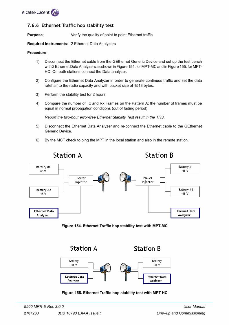
7.6.6 Ethernet Traffic hop stability test
Purpose: Verify the quality of point to point Ethernet traffic
Required Instruments: 2 Ethernet Data Analyzers
Procedure:
1) Disconnect the Ethernet cable from the GEthernet Generic Device and set up the test bench with 2 Ethernet Data Analyzers as shown in Figure 154. for MPT-MC and in Figure 155. for MPT-HC. On both stations connect the Data analyzer.
2) Configure the Ethernet Data Analyzer in order to generate continuos traffic and set the data ratehalf to the radio capacity and with packet size of 1518 bytes.
3) Perform the stability test for 2 hours.
4) Compare the number of Tx and Rx Frames on the Pattern A: the number of frames must be equal in normal propagation conditions (out of fading period).
Report the two-hour error-free Ethernet Stability Test result in the TRS.
5) Disconnect the Ethernet Data Analyzer and re-connect the Ethernet cable to the GEthernet Generic Device.
6) By the MCT check to ping the MPT in the local station and also in the remote station.
Figure 154. Ethernet Traffic hop stability test with MPT-MC
Figure 155. Ethernet Traffic hop stability test with MPT-HC
User Manual
Line–up and Commissioning
9500 MPR-E Rel. 3.0.0
3DB 18793 EAAA Issue 1270/280

7.7 Commissioning station B – Phase 2 (acceptance Test)
Repeat in Station B all the tests performed in Station A except the Hop Stability Test, that has to be per-formed only one time for the full hop.
Fill a second Test Result Sheet for Station B
END OF COMMISSIONING ACCEPTANCE TEST
7.8 Final operations
Complete the commissioning of each NE, creating the NE operator profiles and saving its data.
7.9 Annex A: fine antenna alignment
Safety requirements for workers on antenna pole, and microwave radiations (EMF norms)
SAFETY RULESWhen operating on the antenna pole, strictly follow cautions. In particular do not stand on the antenna axis and beaware of the compliance boundaries.
Antenna pre–pointing should have been done during equipment hardware installation.
This annex explains how to carry out the antenna fine alignment.
To monitor the received level during alignment in the local station:
– use the MPT Rx power monitoring in addition to a voltmeter,
– or, after having logged in the NE, use the Craft Terminal received power measurement facility
Alignment procedure using the MPT Rx power monitoring
a) the radio link must be up and the ATPC disabled
b) in general, fine alignment should be done only on one station of the radio link
c) connect a voltmeter to the MPT (by using the Light Serfice kit cable for the MPT)
d) proceed with Vertical alignment, then with Horizontal alignment
e) in configurations with two antennas, repeat the procedure for the second antenna.
Procedures for Vertical and Horizontal alignment depend on the type of integrated polemounting employed.
Note
User Manual
Line–up and Commissioning
9500 MPR-E Rel. 3.0.0
3DB 18793 EAAA Issue 1 271/280

User Manual
Line–up and Commissioning
9500 MPR-E Rel. 3.0.0
3DB 18793 EAAA Issue 1272/280

ABBREVIATIONS
ABBREVIATION MEANING
ACM Adaptive Coding Modulation
ADM Add Drop Multiplexer
AIS Alarm Indication Signal
ALS Automatic Laser Shutdown
ANSI American National Standards Institute
APS Automatic Protection Switching
APT Active Problem Table
AS Alarm Surveillance
ASAP Alarm Severity Assignment Profile
ATPC Automatic Transmit Power Control
BBE Background Block Error
BER Bit Error Rate
BR & SW Bridge & Switch
Browser Application which allows to browse all RM-MIB objects
CCLNP ConnectionLess Network Protocol
CD Current Data
CDCC Data Communication Channel
CD-ROM Compact Disc Read Only Memory
CES Circuit Emulation Service
CI Communication Infrastructure
CLA Common Loss Alarm
CRU Clock Reference Unit
CTP Connection Termination Point
CT Craft Terminal
User Manual
Abbreviations
9500 MPR-E Rel. 3.0.0
3DB 18793 EAAA Issue 1 273/280

DCI Drop & Continue Interconnection
DCN Data Communications Network
DS Degraded Signal
EC Equipment Controller
ECC Embedded Communication Channels
EFC Ethernet Flow Control
EFD Event Forwarding Discriminator
EML Element Management Layer
EML domain A set of NEs that are maintained by the same EML-OS.
EOW Engineering Order Wire
EPG Eps Protection Group
EPS Equipment Protection Switching
EM-OS Element Manager-Operation System
ES Errored Second
ET Elementary Topology. It is a grouping of some nodes connected according to specific rules. A typical ET is a ring.
ETH ETHernet
ETSI European Telecommunications Standards Institute
EW Early Warning
FCM Fixed Coding Modulation
FCS Frame Check Sequence
FD Frequency Diversity
FE Fast Ethernet
FLS Frame Loss Second
FM FM Fault Management
Gbit/s Gigabits per second
GE Gigabit Ethernet
GFP Generic Frame Protocol
GNE Gateway Network Element
HBER High Bit Error Ratio
ABBREVIATION MEANING
User Manual
Abbreviations
9500 MPR-E Rel. 3.0.0
3DB 18793 EAAA Issue 1274/280

HD History Data
HET Hetero frequency
HS Hitless Switch
HSB Hot Stand-By
HTML HyperText Markup Language
ICP Internal Communication Problem
IDU InDoor Unit
IM Information Model
IP Internet Protocol
IWF Inter-Working Function
IEEE Institute of Electrical and Electronics Engineers
IM Information Manager
JUSM Java User Service Manager
Kbit/s Kilobits per second
LAG Link Aggregation Group
LAN Local Area Network
LAPD Link Access Procedure on D-channel
LBER Low Bit Error Ratio
LDPC Low Density Parity Check
LOF Loss Of Frame
LOS Loss Of Signal
MAC Medium Access Control
Mbit/s Megabits per seconds
MCT Microwave Craft Terminal
MEF Metro Ethernet Forum
MIB Management Information Base
MPR Microwave Packet Radio
MPT-HC Microwave Packet Transport - High Capacity
MSS Microwave Service Switch
NE Network Element
ABBREVIATION MEANING
User Manual
Abbreviations
9500 MPR-E Rel. 3.0.0
3DB 18793 EAAA Issue 1 275/280
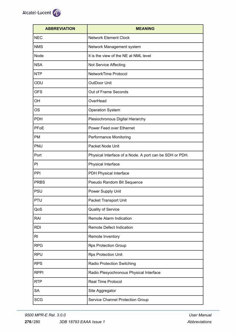
NEC Network Element Clock
NMS Network Management system
Node It is the view of the NE at NML level
NSA Not Service Affecting
NTP NetworkTime Protocol
ODU OutDoor Unit
OFS Out of Frame Seconds
OH OverHead
OS Operation System
PDH Plesiochronous Digital Hierarchy
PFoE Power Feed over Ethernet
PM Performance Monitoring
PNU Packet Node Unit
Port Physical Interface of a Node. A port can be SDH or PDH.
PI Physical Interface
PPI PDH Physical Interface
PRBS Pseudo Random Bit Sequence
PSU Power Supply Unit
PTU Packet Transport Unit
QoS Quality of Service
RAI Remote Alarm Indication
RDI Remote Defect Indication
RI Remote Inventory
RPG Rps Protection Group
RPU Rps Protection Unit
RPS Radio Protection Switching
RPPI Radio Plesyochronous Physical Interface
RTP Real Time Protocol
SA Site Aggregator
SCG Service Channel Protection Group
ABBREVIATION MEANING
User Manual
Abbreviations
9500 MPR-E Rel. 3.0.0
3DB 18793 EAAA Issue 1276/280

SCN State Change Notification
SCU Service Channel Protection Unit
SD Signal Degrade
SDH Synchronous Digital Hierarchy
SES Severely Errored Second
SF Signal Failure
SFP Small Form-factor Pluggable
SONET Synchronous Optical Network
STM Synchronous Transport Module
TCA Threshold Crossing Alarm
TD Threshold Data
TDF Total Discarded Frames
TMN Telecommunications Management Network
TPS Tx Protection Switching
TPG Tps Protection Group
TPU Tps Protection Unit
TRCF Total Received Correct Frames
TRCO Total Received Correct Octets
TRSEF Total Received Service Errored Frames
TRsp Tx Rx spacing
TS Time Slot
TTF Total Transmitted Frames
TTO Total Transmitted Octets
TTP Trail Termination Point
UAS UnAvailable Second
UAT UnAvailable Time
USM User Service Manager
UPA Unavailable path alarm
URU Underlying Resource Unavailable
WTR Wait Time to Restore
ABBREVIATION MEANING
User Manual
Abbreviations
9500 MPR-E Rel. 3.0.0
3DB 18793 EAAA Issue 1 277/280

User Manual
Abbreviations
9500 MPR-E Rel. 3.0.0
3DB 18793 EAAA Issue 1278/280

CUSTOMER DOCUMENTATION FEEDBACK
The meaning of this section is to collect customer feedback about this handbook.
Scope of this activity is the improvement and innovation of customer documentation through the under-standing of customer needs.
Your comments are welcome.
Please send your comment also if you appreciate the handbook.
You can send them to your Local Alcatel-Lucent Technical Assistance Center.
They will be addressed to the team in charge of the relevant manual.
The following form supplies an example only of useful info, as a guide of the type of expected feedback.
It is possible fill part of the form, add other data and so on.
How to send feedback:
• copying the example form, filling it and sending it to your Local Alcatel-Lucent Technical Assis-tance Center. In this case handbook data are already available at the page bottom.
• using the same form available as a file in the relevant documentation CD-ROM, saving, filling and sending it by e-mail to your Local Alcatel-Lucent Technical Assistance Center.
• creating a dedicated form on paper or file and sending it to your Local Alcatel-Lucent Technical Assistance Center.
We’ll take your suggestion in account.
We reserve to modify consequently the handbook according to the corretness and congruence of the sug-gestion and requests.
User Manual
Customer Documentation Feedback
9500 MPR-E Rel. 3.0.0
3DB 18793 EAAA Issue 1 279/280

280
CUSTOMER DOCUMENTATION FEEDBACK
Handbook DataHandbook title, release,version:Handbook type:Handbook part number and edition:
General Feedback EvaluationSUBJECT 5(max) 4 3 2 1 (min)
Total evaluationInfo quantityInfo qualityInfo structureConsulting facilityLayout
Chapters Feedback EvaluationHANDBOOK PARTS 5(max) 4 3 2 1(min)
PREFACECHAPTER 1CHAPTER 2CHAPTER 3CHAPTER 4CHAPTER 5CHAPTER 6CHAPTER 7Your Comments (stricltly necessary when value is less than 3):
Suggestion for ImprovementWhich subject to deepen:
How to deepen:
Subject to eliminate or reduce
Other comments/suggestions
Errors Identified
Reader InfoName:Company:Address:E-mail:Phone:
User Manual
Customer Documentation Feedback
9500 MPR-E Rel. 3.0.0
3DB 18793 EAAA Issue 1280/280

3DB 18793 EAAA Edition 1

w
All rights reserved.Passing on and copying of this document,
use and communication of its contents is not permittedwithout written authorization from Alcatel -Lucent.
ww.alcatel-lucent.com