mppt based autonomous pv module with sensor less...
TRANSCRIPT
MPPT Based Autonomous PV Module withSensor Less Control of BLDC Motor forMaximum Solar Power GenerationsSundaram A.* and G.P. Ramesh**
ABSTRACT
This Paper presents the efficient power generation of Photovoltaic System and also deals with the sensor lesscontrol of BLDC motor. The controller design of an Autonomous PV Module (APVM) has found a lot of attentionsin maximum power point tracking (MPPT) for PV system applications. It consists of a PV panel and a Non-inverting Four Switch buck-boost Converter (NFSBBC) for maximum power generations. The mathematical modelof single diode Photovoltaic cell has found to be better and accurate at wide variations of irradiance and temperature.This NFSBBC can be operating in buck, boost and buck–boost modes addition with reduced number of passivedevices and non-inverted output voltage polarity. The sensor less control of BLDC motor based on a hysteresiscomparator and a potential start-up method with a high starting torque are indicated. The hysteresis comparator isutilized to compensate the phase delay of the back EMFs due to a Low-Pass Filter (LPF) and used to preventingmultiple transition output from ripple or noise in terminal voltage. The rotor position is aligned at standstill for highstarting torque without any additional sensor and information about motor parameters. Also, the stator current canbe easily controlled by switching sequence of controller during alignment. The controller performance of APVMand corresponding simulation results are applied to sensor less control of BLDC motor and verified performanceresults using MATLAB/Simulink environment.
Keywords: NFSBBC, Photovoltaic (PV) System, MPPT/ P&O, BLDC motor, Hysteresis control, SPWM,APVM
1. INTRODUCTION
Renewable power is having more attention in power generation in increasing global warming today. In thisespecially solar power generation is a great attention in last decades [1]. In Existing system of solar powergeneration is arranged by series [2] and parallel [3] connection of solar cells, single and multiple invertersfor high power and high efficiency conversion respectively. The main drawback of micro-inverter system ishaving low PV (Photovoltaic) power, large difference of voltage between input side and output side. Thisis because of shading effect or incompatible module of Photovoltaic Array so this is causes less efficiencyand required high rating of power switches. The efficiency and maximum power point tracking ofPhotovoltaic Source is achieved by special converters such as Cuk and SEPIC converter are implementedto extract the power at maximum with high efficiency [4]. The notable drawback of above converter systemis required many passive components in nature.
The less number of passive components with high efficiency range is obtained by applying four-switchbuck-boost converter for medium power rating of solar power generation. Special features includes in four-switch inverter circuit are such as low rating of passive components rating, high step up and high step downcapability compared with other power converters[5].
* Research Scholar, Department of Electrical and Electronics Engineering, St. Peter’s University, Avadi, Chennai–600054, India,Email: [email protected]
** Department of Electronics and Communication Engineering, St. Peter’s University, Avadi, Chennai–600054, India.
I J C T A, 9(6), 2016, pp. 2911-2922© International Science Press
ISSN: 0974-5572

2912 Sundaram A. and G.P. Ramesh
Even it has particular range of power conversion not in wide range. To overcome the above demeritsa new enhancement of non-inverting polarity of Non-inverting four-switch buck-boost converter(NFSBBC) is proposed in this configuration because this is having less number of passive componentswith meet out the demands for power extraction, efficiency and wide power range of power extractionby suitable selection of passive device rating. Due to low power and high speed operation of drive,Brushless DC Motor (BLDC) motor is applied for much more application in recent decades such asautomotive, computer, industrial, household and recently in heavy drives also and etc [6]. Classicalapproach of sensor control using Hall Effect for Brushless DC Motor (BLDC) is applied to sensingposition of rotor [7]. So this is used to drive exact commutation of current. The influence of maintenanceand cost is the reason for developing a sensor less algorithm to special drives especially in BrushlessDC motor Drives (BLDC). The sensor less control loop is provides a less maintenance cost and highreliability in nature.
This paper is proposed a sensor less control of brushless DC motor using hysteresis comparator byovercoming the limitation of sensor control loop. Control loop drives accurate commutations of current byappropriate switching pulse generation and increasing inner loop speed matching to outer loop of system.A new enhanced approach of maximum power extraction for photovoltaic system was implemented usingnon-inversion four-switch buck boost converter. The proposed MPPT approach is reached maximumefficiency, reliability and high ratio of power conversion with less number of passive device and rating. Theeffectual performance of MPPT using proposed converter topology and sensor-less approach using hysteresisband control and details is given in chapter III and chapter IV respectively.
2. AUTONOMOUS PHOTOVOLTAIC SYSTEM USING MPPT TOPOLOGY
The presented a new enhanced Non-inverting four switch buck boost converter (NFSBBC) using perturbsand observer based MPPT topology is proposed in proposed autonomous photovoltaic systems. The presentautonomous system is applied for Brushless DC Motor control. Four switch converter design and detailsand Autonomous photovoltaic module is described below.
2.1. Non-inverting four switch buck-boost converter (NFSBBC)
The Non-inverting Four Switch Buck Boost Converter (NFSBBC) is a family of buck boost convertertopology. But this is separated from classical buck-boost, SEPIC and Cuk converter in the form of reliability,efficiency, high step-up and step-down capability, less number of passive components and low range ofcomponents. The design aspects of proposed converter system are obtained by voltage-second balancedtheorem. The gain of voltage G
V is obtained by
1
21out
VPV
V DG
V D (1)
D1, D
2 are derived duty cycles for S
A and S
B switch which presented in proposed converter system. S
A1, S
A2
are rectifier switches for SA, S
B switches. Pulse width modulation is designed on the basis of continuous and
discontinuous operation. The nature of proposed converter topology is discontinuous power flow in betweenbuck (step-down) and boost (step-up) operation. So this discontinuous is needed to change continuousoperation for smooth and steady state operation of voltage. Carrier overlapping scheme is introduced forreference signal comparison to delivered exact pulse duty cycles of D
1, D
2 [8]. Reference signal generation
and magnitude is important phenomena for proposed Buck-Boost operation and also high step-up ratio. Sothis is derived by adequate MPPT algorithm using perturb and observer method [9]. Due to the condition ofphotovoltaic system proposed MPPT extract power by using adequate reference signal generation forNFSBBC circuit and duty cycles D
1, D
2 are shown in Fig. 1 and Fig. 2.

MPPT Based Autonomous PV Module with Sensor Less Control of BLDC Motor... 2913
Figure 1: A new Enhanced Photovoltaic Power Generation forBLDC Motor using sensor-less Hysteresis PWM Control
Figure 2: Control Pulses for Non-inverting Four Switch Buck Boost converter(NFSBBC)

2914 Sundaram A. and G.P. Ramesh
2.2. Autonomous photovoltaic system using NFSBBC circuit
The voltage gain is derived by using transfer function from load side voltage to source side voltage transferfunction G
oi and Obtained duty cycle to input voltage transfer function using continuous conduction mode
is represented by Gi1, G
i2. The equivalent circuit of Non-inverting circuit is an ideal form shown in Fig. 3.
Load side voltage of circuit and source side voltage of circuit is represented by fixed voltage source converter.
Figure 3: Equivalent Circuit for Autonomous Photovoltaic System
In equivalent circuit, is denoted as input series resistance for capacitor across input side of transferfunction. Maximum value of voltage is derived using perturb and observer method by
( )( )
1PVMPP PV
PV MPP PV
i
V R (2)
The detailed deviation of mathematical function is expressed by following
1 0
2 0
122
1
0
11
10
zdPVoi d
o
s
wV DG s
V D s s
qw w
�
�
�
�(3)
0 0
2 0
1 21 2
11
0
1 1
10
z zVPV PVi d
s s
w wV VG s
Dd s s
qw w
��
�
�(4)
0 0
1 0
102 2
12
0
1
10
zVPVi d
s
wV VG s
Dd s s
qw w
�
�
�
�(5)
MPPT Based Autonomous PV Module with Sensor Less Control of BLDC Motor... 2915
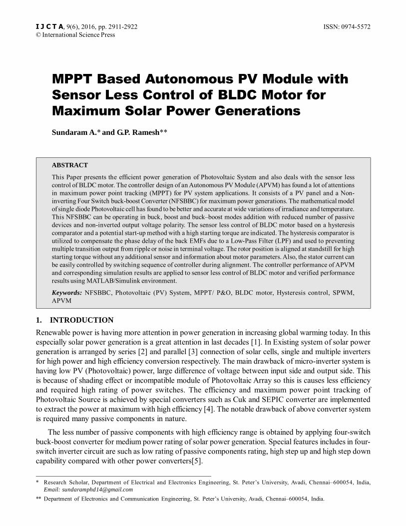
Where21( )
0MPP PV D
CMPP PV
Rw
LC R R (6)
21
2
1
MPP PV D
c
MPP PV D cMMP PV
QRL
R CR LC R R
(7)
1
1z
c
WR C (8)
12
PVz
L
V DW
LI (9)
3. PROPOSED SENSOR-LESS CONTROL USING HYSTERESIS COMPARATOR
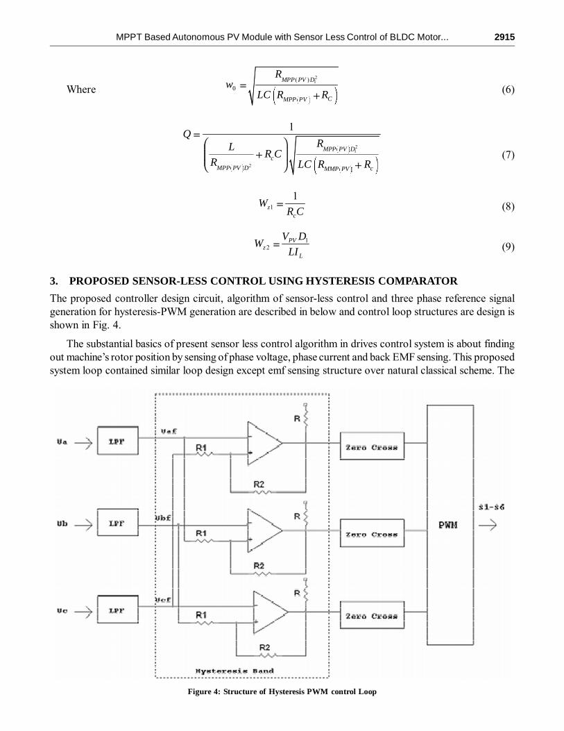
The proposed controller design circuit, algorithm of sensor-less control and three phase reference signalgeneration for hysteresis-PWM generation are described in below and control loop structures are design isshown in Fig. 4.
The substantial basics of present sensor less control algorithm in drives control system is about findingout machine’s rotor position by sensing of phase voltage, phase current and back EMF sensing. This proposedsystem loop contained similar loop design except emf sensing structure over natural classical scheme. The
Figure 4: Structure of Hysteresis PWM control Loop

2916 Sundaram A. and G.P. Ramesh
enhancement of sensor less control structure shown in Fig. 4 is initially three phase voltages are measuredand given to Low Pass Filter (LPF). Low pass filter is used as noise suppression or neglect.
Voltage reference signal is denoted by (Ureff
) is obtained by low pass filter and this is compared withU
reff*. The comparison between actual controller voltage source and reference signals is closed to nature.
Reference of voltage is naturally close to back emf so we can easily identify about commutation of BrushlessDC Motor (BLDC) to provide exact excitation for two phases of Brushless DC Motor (60° – 120°) at atime. The signal comparison is given to as Hysteresis band pass filter input. Presented hysteresis basedband pass filter circuit provides an adequate reference signals for pulse width modulation generation usingsine PWM topology. This type of pulse width modulation is separated from classical logic operator basedpulse generation method. Important features of hysteresis band to provide exact gate pulse signals to controlof commutation current which present on phase line and inverter circuit. The working principles of hysteresisband comparator with respect to time which is shown in Fig. 5.
The present low pass filter cut-off frequency is can easily affect torque signal and speed signal onBrushless DC Motor load performance [10]. Harmonics and noises are easily appear by variation of cut-offfrequency so utilizing of low pass filter in control circuit is in desired frequency limits in the range 2.6 kHz.
The phase difference between filtered output signals and actual signals draws from phase line of inverterapplied across hysteresis band to obtained desired commutation of reference signals. Phase A is applied toinverter leg to lead signal in desired range and other hand phase C is applied through Resistance of phasesignal. The phase difference between filter and resistance is expressed by
0
1
1 1da af a cf
nU V U V
n n(10)
Where, Vaf, is a filtered reference signal,
1
L
Rn
R is a differenced signal is obtained by resistance of
phase line in C or A. Equation in above (10) U0a
is positive means U0a
= + Usat
. If the condition is negative
Figure 5: principles of proposed hysteresis pulse width modulation

MPPT Based Autonomous PV Module with Sensor Less Control of BLDC Motor... 2917
for phase terminals of C is denoted by Vcf. At U
0a = – U
sat, load terminal voltage U
0a switches back to + U
sat,
when differential form of voltage is positive (10) i.e the condition derived by following manner,
1 11cf af satV V U
n n (11)
1
n Usat
In equation (10) and (11) is a hysteresis band which is determined by output voltage level Usat
and resistance ration which is denoted by n. in equation (10) and (11) right side of equation is multiplied by
upper and lower level of threshold voltage of UUT
and ULT
respectively. Those are multiplied by 1
1n
[10] is denoted by,
1 11UT af satU V U
n n (For upper threshold value) (12)
1 11LT af satU V U
n n (For lower threshold value) (13)
The load terminal voltage of +Usat
and Vcf
is smaller than ULT
then switches to –Usat
. The same conditionis bellow of U
LT then terminal voltage is +U
sat. The real commutation signal for phase A is Za is generated
from low pass filter at ta. Time function of U
LT is described by
max12 1 11LT sat
s
VU t t V
T n n (14)
Where Vmax
, is a maximum voltage of terminals, Ts is total time of performance of terminal voltage.
Using equation (14), time interval of tc at the terminals between U
LT and V
cf is expressed by
1
2 1 1s sat
cmax
T Unt
n n V (15)
ta, is a interval between t
c and
2sT
is expressed by
2s
a c
Tt t (16)
In equation (16), equation (15) is applied and described about angle of phase A is �a by
Table I
U0
U0 – 120° U
0 – 240° U
1 – 120° U
1 – 240°
11
2 1s sat
a tamax
T Uw
n V (17)
Angle �a is inversely proportional to resistance value on phase line. If resistance decreases then angle
will be increase and maximum of voltage Vmax
also decreases. Lagging of signal is can be compensated by
2918 Sundaram A. and G.P. Ramesh
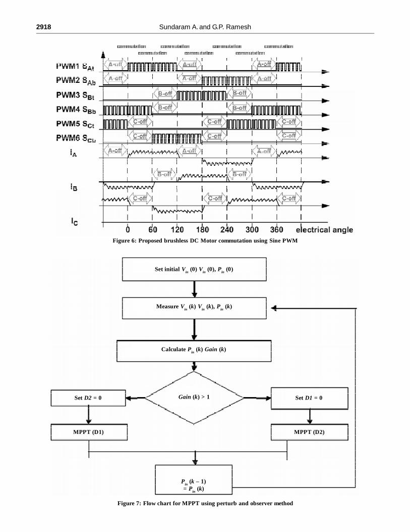
Figure 6: Proposed brushless DC Motor commutation using Sine PWM
Figure 7: Flow chart for MPPT using perturb and observer method
Set initial Vin (0) V
in (0), P
in (0)
Measure Vin (k) V
in (k), P
in (k)
Calculate Pin (k) Gain (k)
Set D2 = 0
MPPT (D1)
Gain (k) > 1 Set D1 = 0
MPPT (D2)
Pin (k – 1)
= Pin (k)

MPPT Based Autonomous PV Module with Sensor Less Control of BLDC Motor... 2919
varying resistance value n across phase terminals. Low pass filter is range limits are fixed in +1V, resistancevalue is varied up to 1.2; maximum peak voltage V
max is 1.2 V. The table I: is shown about a single sequence
for proposed three phase inverter and Sequence UVW are applied to three phase inverter for forwarddirection. WUV sequence is taken in account for reverse direction. Given sequence table is applied andused in generated pulse width modulation which is shown in Fig. 6.
4. SIMULATION RESULTS
The present converter system is provides a maximum power generation from solar power using perturb andobserver method shown in Fig. 7 and this is applied to brushless DC motor control using sensor less basedhysteresis PWM generation. The circuit of proposed implementation is developed using MATLAB/Simulinkwhich is shown in Fig. 8. Present converter of buck boost conversion capability of voltage performanceacross DC-Link voltage is shown in Fig. 9. Proposed hysteresis band used to control of lag and lead ofphase voltage angle to control of speed and torque of brushless DC Motor is specification is in Table-II.This controller is cost effective compared with sensor and other sensor less method because this is requiredphase voltage alone to finding rotor‘s condition and adequate pulse width modulation generation. Thecontrol performance is verified using simulation result through motor performance is shown in Fig. 10, 11and 12.
5. CONCLUSION
The topology of Non Inverting Four Switch Buck Boost Converter (NFSBBC) is provided a maximum ofpower extraction from solar panel. The special features of proposed NFSBBC are having less number ofcomponents with high efficiency and this is used to provide continuous power supply to three phase inverterfed brushless DC Motor. Buck boost operation of present converter is operated is based on condition ofsolar panel and internal generation capacity. Extraction of power is improved by proposed perturb and
Table 2Specification of parameters
Converter specification
Name Value
VPV
(V) 25
IPV
(A) 2.5
PPV
(W) 62
Vout
(V) 60
L(�H) 800
C1(�F) 200
C2(�F) 200
R(m�) 50
L(mH) grid side 1
C1(nF) grid side 1
Motor Specification
Rated voltage(V) 60
Rated Current(A) 3A
Nominal speed (rpm) 3000
Stator Resistance(�) 0.19
Stator Inductance(mH) 0.835
Rotor moment of inertia J(kg.m2) 1.9959µ

2920 Sundaram A. and G.P. Ramesh
Figure 8: Simulation implementation circuit for proposed topology
Figure 9: DC-Link Voltage of non inverting four switch buck boost converter (a)
(a)

MPPT Based Autonomous PV Module with Sensor Less Control of BLDC Motor... 2921
(b)
Figure 10: stator phase current: (a) per phase stator current signals (b) combined three phase signal
Figure 11: Electromagnetic torque performance
Figure 12: Speed performance of brushless DC Motor in RPM

2922 Sundaram A. and G.P. Ramesh
observer method and also brushless DC Motor is controlled by effective sensor less based hysteresis PWMcontrol. The present hysteresis band is used to control of phase voltage angle so we can obtained betterelectromagnetic torque and speed of brushless DC Motor performance. Buck-boost operation andperformance of present converter and enhanced hysteresis based sensor less PWM control topologyperformance also given in details in this paper. Topology was implemented using MATLAB/Simulink andresult was proved in the improvement in the form of converter and motor performance over existing topology.
REFERENCES[1] Chen, Cheng-Wei, Kun-Hung Chen, and Yaow-Ming Chen. “Modeling and controller design of an autonomous PV module
for DMPPT PV systems.” Power Electronics, IEEE Transactions on 29.9 (2014): 4723-4732.
[2] Walker, Geoffrey R., and Paul C. Sernia. “Cascaded DC-DC converter connection of photovoltaic modules.” PowerElectronics, IEEE Transactions on 19.4 (2004): 1130-1139.
[3] Gules, Roger, et al. “A maximum power point tracking system with parallel connection for PV stand-alone applications.”Industrial Electronics, IEEE Transactions on 55.7 (2008): 2674-2683.
[4] Mangu, B., and B. G. Fernandes. “Efficiency improvement of solar-wind based dual-input Cuk-SEPIC converter fortelecom power supply.” IECON 2012-38th Annual Conference on IEEE Industrial Electronics Society. IEEE, 2012.
[5] Orellana, Marcos, Stephane Petibon, Bruno Estibals, and Corinne Alonso. “Four Switch Buck-Boost Converter forPhotovoltaic DC-DC power applications.” In IECON 2010-36th Annual Conference on IEEE Industrial ElectronicsSociety, pp. 469-474. IEEE, 2010.
[6] Kim, Tae-Hyung, and Mehrdad Ehsani. “Sensorless control of the BLDC motors from near-zero to high speeds.” PowerElectronics, IEEE Transactions on 19.6 (2004): 1635-1645.
[7] Wu, Yuanyuan, et al. “Position sensorless control based on coordinate transformation for brushless DC motor drives.”Power Electronics, IEEE Transactions on 25.9 (2010): 2365-2371.
[8] Y.J. Lee, A. Khaligh, and A. Emadi, “A Compensation Technique for Smooth Transitions in a Noninverting Buck–BoostConverter,” IEEE Transactions on Power Electronics, vol. 24, no. 4, pp. 1002-1015, April 2009.
[9] N. Femia, G. Petrone, G. pagnuolo, and Vitelli, “Optimization of perturb and observe maximum power point trackingmethod,” IEEE Transactions on Power Electronics, vol. 20, no. 4, pp. 963-973, July 2005.
[10] Chun, Tae-Won, et al. “Sensorless control of BLDC motor drive for an automotive fuel pump using a hysteresis comparator.”Power Electronics, IEEE Transactions on 29.3 (2014): 1382-1391.