mpls oam technology white paperworking lsp, an lsp (pea p2 peb) with the same source and destination...
TRANSCRIPT

MPLS OAM Technology White Paper
Issue 01
Date 2012-10-30
HUAWEI TECHNOLOGIES CO., LTD.

Issue 01 (2012-10-30) Huawei Proprietary and Confidential
Copyright © Huawei Technologies Co., Ltd.
i
Copyright © Huawei Technologies Co., Ltd. 2012. All rights reserved.
No part of this document may be reproduced or transmitted in any form or by any means without prior
written consent of Huawei Technologies Co., Ltd.
Trademarks and Permissions
and other Huawei trademarks are trademarks of Huawei Technologies Co., Ltd.
All other trademarks and trade names mentioned in this document are the property of their respective
holders.
Notice
The purchased products, services and features are stipulated by the contract made between Huawei and
the customer. All or part of the products, services and features described in this document may not be
within the purchase scope or the usage scope. Unless otherwise specified in the contract, all statements,
information, and recommendations in this document are provided "AS IS" without warranties, guarantees or
representations of any kind, either express or implied.
The information in this document is subject to change without notice. Every effort has been made in the
preparation of this document to ensure accuracy of the contents, but all statements, information, and
recommendations in this document do not constitute a warranty of any kind, express or implied.
Huawei Technologies Co., Ltd.
Address: Huawei Industrial Base
Bantian, Longgang
Shenzhen 518129
People's Republic of China
Website: http://enterprise.huawei.com

MPLS OAM Technology White Paper About This Document
Issue 01 (2012-10-30) Huawei Proprietary and Confidential
Copyright © Huawei Technologies Co., Ltd.
ii
About This Document
Abstract:
OAM plays a very important role in the public telecom network, especially for the
QoS-guaranteed network. OAM can simplify network operations, test network performance,
and reduce network operation costs. As the key bearer technology of the scalable
next-generation network, MPLS can provide multiple services with guaranteed QoS.
Therefore, the MPLS network urgently requires OAM capabilities. This document describes
the technical principles, implementation, and typical applications of MPLS OAM.
Keywords:
MPLS, OAM, PS, CV, FFD, FDI, BDI

MPLS OAM Technology White Paper Contents
Issue 01 (2012-10-30) Huawei Proprietary and Confidential
Copyright © Huawei Technologies Co., Ltd.
iii
Contents
About This Document .................................................................................................................... ii
1 MPLS OAM Overview ................................................................................................................. 1
2 Technology Overview .................................................................................................................. 2
2.1 MPLS OAM Overview .................................................................................................................................... 2
2.2 Protection Switching Overview........................................................................................................................ 3
2.2.1 1:1 Protection Switching ......................................................................................................................... 4
2.2.2 1+1 Protection Switching ........................................................................................................................ 5
3 Key Technology ............................................................................................................................. 6
3.1 Example ........................................................................................................................................................... 6
3.2 Technology ....................................................................................................................................................... 7
3.2.1 CV Monitoring ........................................................................................................................................ 7
3.2.2 FFD Monitoring ...................................................................................................................................... 8
3.2.3 Backward Defect Indication (BDI) ......................................................................................................... 8
3.2.4 Forward Defect Indication (FDI) ............................................................................................................ 9
3.2.5 Auto Negotiation Mechanism (First-Packet Triggering, Auto-Sensing) ............................................... 10
3.2.6 Binding the Backward Path ................................................................................................................... 11
3.3 Terms .............................................................................................................................................................. 12
4 Typical Applications .................................................................................................................. 15
4.1 Terminal Network Faults ................................................................................................................................ 15
4.2 Hierarchical OAM .......................................................................................................................................... 15
4.3 Testing the Entire LSP .................................................................................................................................... 16
5 Conclusion .................................................................................................................................... 17
6 References ..................................................................................................................................... 18
A Abbreviation ............................................................................................................................... 19

MPLS OAM Technology White Paper 1 MPLS OAM Overview
Issue 01 (2012-10-30) Huawei Proprietary and Confidential
Copyright © Huawei Technologies Co., Ltd.
1
1 MPLS OAM Overview
MPLS OAM technology provides the MPLS network with a defect-detection tool and a
defect-rectification mechanism that are independent of any Layer 3 or Layer 2 protocols. The
check function of the CR-LSP forwarding plane is implemented through MPLS OAM and
protection switching. The protection switching is performed 50 ms after a defect occurs so
that the impact of the defect is minimized. This document describes the background and
working principles of MPLS OAM. The intended audience needs to know MPLS and MPLS
OAM.
The server-layer that bears MPLS, such as SONET/SDH, and the client-layer that uses MPLS,
such as IP, FR, and ATM, have their respective OAM mechanisms. Failures of the MPLS
layer network cannot be solved thoroughly through the OAM mechanism of other layers. In
addition, the network technology hierarchy also requires MPLS to have its independent OAM
mechanism to decrease the dependency of layers on each other.
In fact, MPLS OAM provides a set of check mechanisms for the MPLS user layer. MPLS
OAM is independent of other network layer and provides the state information of LSP for
users, abundant LSP diagnosis interfaces for network management and maintenance personnel,
and references for network performance detection and user accounting. While providing a
check tool, MPLS OAM has a complete protection switching mechanism and can switch user
data within 50 ms after the MPLS layer detects defects, which minimizes the loss of user data.

MPLS OAM Technology White Paper 2 Technology Overview
Issue 01 (2012-10-30) Huawei Proprietary and Confidential
Copyright © Huawei Technologies Co., Ltd.
2
2 Technology Overview
2.1 MPLS OAM Overview
MPLS OAM checks the connectivity of a single LSP from the source end to the destination
end. As shown in Figure 2-1, the ingress node periodically sends an OAM continuity check
(CV) packet and the egress node checks it periodically. The transit node makes pass-through
processing. When the destination end detects a defect, it sends Backward Defect Indication
(BDI) packets to the LSP source node through the bound return path to fulfill protection
switching.
Figure 2-1 Networking diagram of MPLS OAM connectivity detection
An OAM packet can be considered as an MPLS data packet, but the OAM packet carries
control information. The OAM packet is encapsulated as an MPLS packet on the ingress node.
That is, the outer label of the packet is the out-label of the LSP on this node. The inner label is
set to 14 (OAM Route alert label). The other bits are the payload of the OAM protocol packet,
as shown in Figure 2-2. When the egress node detects a defect, the egress node notifies the
ingress node using a notification packet. In this way, the source and destination nodes of the
LSP learn about the current status of the LSP to provide the client-layer with status
information of the entire LSP. The status information helps determine whether to trigger
protection switching.

MPLS OAM Technology White Paper 2 Technology Overview
Issue 01 (2012-10-30) Huawei Proprietary and Confidential
Copyright © Huawei Technologies Co., Ltd.
3
Figure 2-2 Unidirectional check principle
Figure 2-3 shows the format of an MPLS OAM packet header.
Figure 2-3 Format of an OAM packet header
MPLS OAM packets are differentiated from common user plane traffic by an increase of 1 in
the label stack at a given LSP level at which they are inserted. Compared with a common
MPLS packet, an OAM packet header has the following characteristics:
The value 14 in the Label field indicates an OAM packet.
The TTL field is set to 1 to ensure that OAM packets are transmitted to the LSR that is
the LSP egress monitored by OAM.
An OAM packet is transparent to the transit LSR and the penultimate LSR. MPLS OAM
applies mainly to ER LSPs, which refer to TE tunnels.
2.2 Protection Switching Overview
Protection switching is a protection mechanism for complete provisioning and can be used on
any topology. The route and bandwidth of the protection LSP are reserved for the working
LSP. When the working LSP is likely to become faulty, protection must be implemented in all
cases. Therefore, the protection LSP must be a completely different physical channel in fact.
Only in this way can common faults be rectified. In addition, the working LSP cannot
transmit packets along the shortest path.

MPLS OAM Technology White Paper 2 Technology Overview
Issue 01 (2012-10-30) Huawei Proprietary and Confidential
Copyright © Huawei Technologies Co., Ltd.
4
2.2.1 1:1 Protection Switching
Figure 2-4 Traffic when links are working properly
The 1:1 switching mode indicates that a protection LSP is used to take the place of a working
LSP when the working LSP fails. Working and protection LSPs are established on the ingress
node. When the links are working properly, the traffic is relayed to the working LSP through
the selector on the ingress. The protection LSP does not have the traffic that is transmitted on
the working LSP.
Figure 2-5 Traffic when the working LSP is faulty
After the egress node finds that the link on the working LSP has failed, user data is switched
to the protection LSP. The egress node sends BDI packets to the ingress node through the
backward path to request the ingress node to perform the switching.
After the ingress node receives the BDI packets, it relays the selector to the protection LSP
and switches the traffic from the working LSP to the protection LSP. In this way, 1:1
protection is implemented.
Working traffic
Path Switch LSR
Source of the protected domain Permanent merge
Working LSP
Protection LSP
Sink of the protected domainSelector
Working traffic
CV packet insertion
CV packet extraction
Path Merge LSR with a merging selector
Working traffic
Path Switch LSR
Source the of protected domain Permanent merge
Working LSP
Protection LSP
Sink of the protected domainSelector
Working traffic
CV packet insertion
CV packet extraction
Path Merge LSR with a merging selector

MPLS OAM Technology White Paper 2 Technology Overview
Issue 01 (2012-10-30) Huawei Proprietary and Confidential
Copyright © Huawei Technologies Co., Ltd.
5
2.2.2 1+1 Protection Switching
Figure 2-6 Traffic when links are working properly
Working traffic
Path Switch LSR
Source of the protection domain Permanent bridge
Working LSP
Protection LSP
Sink of the protection domain Selector
Path Merge LSR
CV packet insertion
CV packet extr action
In the 1+1 architecture, a protection LSP is dedicated to a working LSP. On the source end of
the protection domain, user data is transmitted to the destination end of the protection domain
on both the working and protection LSPs. The destination end selects one from the working
and protection LSPs to receive the user data. In this way, the user services are transmitted on
both the working and protection LSPs. Whether the destination end selects the working LSP
or protection LSP to receive data depends on the protection mechanism.
Figure 2-7 Traffic when the working LSP is faulty
Working traffic
Path Switch LSR
Source of the protection domain Permanent bridge
Working LSP
Protection LSP
Sink of the protection domain
Selector
Path Merge LSR
C V packet insertion
CV packet extraction
After the MPLS OAM check tool finds that the working LSP has failed, the destination end
switches the path for receiving user data from the working LSP to the protection LSP. In this
way, 1+1 protection switching is implemented. The source end does not perform any
switching in this case.

MPLS OAM Technology White Paper 3 Key Technology
Issue 01 (2012-10-30) Huawei Proprietary and Confidential
Copyright © Huawei Technologies Co., Ltd.
6
3 Key Technology
3.1 Example
The following example illustrates the working principle and process of MPLS OAM.
Figure 3-1 Working principle of MPLS OAM
PE-A PE-B
CE
CE
CE
CE
Working LSP
Protection LSP
P-1
P-2
The red TE LSP (PEAP1PEB) in Figure 3-1 indicates the working LSP. To protect the
working LSP, an LSP (PEAP2PEB) with the same source and destination ends needs to
be established, which is indicated in green. 1:1 protection switching is used. The OAM check
function is enabled on the working LSP (red). On PEB, the backward LSP of the working LSP
is specified. The backward LSP is established in advance and can have the same path as the
protection LSP but in the opposite direction.
The working LSP sends connectivity verification (CV) packets at a fixed interval of 1s on
PEA. The destination end specifies a slide window of 1s. The destination end monitors and
statistically analyzes CV packet correctness within 3s. This is the criteria for determining the
LSP status.

MPLS OAM Technology White Paper 3 Key Technology
Issue 01 (2012-10-30) Huawei Proprietary and Confidential
Copyright © Huawei Technologies Co., Ltd.
7
A CV packet is a low-rate check packet and cannot meet the requirements for fast switching
in some important scenarios. Therefore, it is recommended to use the fast failure detection
(FFD) packets with a higher transmission rate instead of CV packets. The working LSP sends
FFD packets periodically at a fixed rate on PEA. The destination end monitors and
statistically analyzes FFD packet correctness within a period three times the check interval.
This is the criteria for determining the LSP status. The FFD packets have the same functions
with CV packets, but have an adjustable rate and a shorter check interval.
After the destination end detects a defect on PEB, the destination end sends BDI packets to
the source end through the backward path. The backward path must be an LSP. In this
example, the backward path is from PEB to P2 and then to PEA. After the source end receives
the BDI packets, it locates the working LSP according to the packet information and performs
the switching according to the corresponding information about the protective group. That is,
the user data is switched to the protection LSP for transmission.
3.2 Technology
The preceding example illustrates the following key technologies of MPLS OAM.
3.2.1 CV Monitoring
The LSP source node sends CV packets a fixed interval of 1s. The destination end monitors
and statistically analyzes CV packet correctness within a period three times the check interval.
This is the criteria for determining the LSP status. A CV packet is usually used for the
availability detection of a common LSP because the generation rate is low and cannot be
adjusted. Figure 3-2 shows the format of a CV packet. The Function Type field is fixed at
0x01.
Figure 3-2 Format of a CV packet
MPLS OAM Technology White Paper 3 Key Technology
Issue 01 (2012-10-30) Huawei Proprietary and Confidential
Copyright © Huawei Technologies Co., Ltd.
8
3.2.2 FFD Monitoring
FFD provides the detection mechanism for the LSP of the P2P type. The LSP source node
periodically sends FFD packets at a configurable rate of 10 ms, 20 ms, 50 ms, 100 ms, 200 ms,
or 500 ms. The destination end monitors and statistically analyzes FFD packet correctness
within a period three times the check interval. This is the criteria for determining the LSP
status. The FFD packets have the same functions with CV packets, but have an adjustable rate
and a shorter check interval. Therefore, FFD packets apply to the check of an LSP in Server
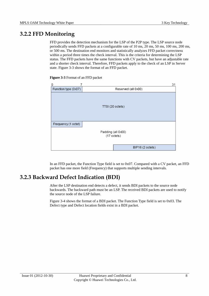
state. Figure 3-3 shows the format of an FFD packet.
Figure 3-3 Format of an FFD packet
In an FFD packet, the Function Type field is set to 0x07. Compared with a CV packet, an FFD
packet has one more field (Frequency) that supports multiple sending intervals.
3.2.3 Backward Defect Indication (BDI)
After the LSP destination end detects a defect, it sends BDI packets to the source node
backwards. The backward path must be an LSP. The received BDI packets are used to notify
the source node of the LSP failure.
Figure 3-4 shows the format of a BDI packet. The Function Type field is set to 0x03. The
Defect type and Defect location fields exist in a BDI packet.

MPLS OAM Technology White Paper 3 Key Technology
Issue 01 (2012-10-30) Huawei Proprietary and Confidential
Copyright © Huawei Technologies Co., Ltd.
9
Figure 3-4 Format of a BDI packet
The TTSI field in a BDI packet is optional. The TTSI is necessary when a shared backward
tunnel or out-of-band backward tunnel is used. For a bidirectional LSP, this field can be filled
with 0. If the TTSI is used, the value of the field is the TTSI of the LSP. For details, see TTSI
index mode.
If the FDI packet reported by the lower level LSP is received, the Defect type and the Defect
location fields are generated according to the corresponding fields of the FDI packet.
3.2.4 Forward Defect Indication (FDI)
A forward defect indication (FDI) packet is generated by the LSR detecting defects. An FDI
packet is a response to the defects detected by a CV or FFD packet. For the lower level LSP:
The source end of the LSP uses a FDI packet to inform the destination end of the defect.
When the auto protocol is enabled, the source end of the LSP requests the destination
end to stop OAM detection.
Figure 3-5 shows the format of an FDI packet. The Function Type field is set to 0x02. The
Defect type and Defect location fields exist in an FDI packet.

MPLS OAM Technology White Paper 3 Key Technology
Issue 01 (2012-10-30) Huawei Proprietary and Confidential
Copyright © Huawei Technologies Co., Ltd.
10
Figure 3-5 Format of an FFI packet
The node that first detects a defect sends an FDI packet to the downstream node. The TTSI
field in the FDI packet is optional. It is used when the penultimate hop popping (PHP) is
applied. In other cases, the TTSI is not used and is set to 0. For details, see TTSI index mode
section 3.2.6 "Binding the Backward Path."
The FDI packet is reported to one higher level after another. When a higher level LSP detects
defects by its own CV or FFD packet, the LSP also receives the FDI packet reported by the
lower level LSP. Therefore, it can be concluded that the defect occurs at the lower level.
The protocol does not include the MPLS OAM notification mechanism. When the MPLS
OAM function on the source end is disabled, the destination end still monitors defects at a
fixed interval. As a result, the check results are incorrect, subsequent switching is unnecessary,
and data forwarding is affected. To solve this problem, an error code is added to the FDI
packet, which is used to request the destination end to stop MPLS OAM check.
3.2.5 Auto Negotiation Mechanism (First-Packet Triggering, Auto-Sensing)
MPLS OAM is implemented based on the successful establishment of LSPs. When the
destination end just starts using OAM, the OAM mechanism cannot differentiate the
following situations:
1. OAM is disabled on the source end so that CV or FFV packets cannot be sent.
2. The physical link is disconnected.
In either situation, the destination end does not detect any CV or FFD packets. Then the
mechanism of first-packet triggering is proposed. First-packet triggering indicates that the
LSP destination end enables the MPLS OAM check function only after receiving a CV or
FFD packet for the first time. In a specified period (configurable) when the destination end
does not receive any CV or FFD packets before the check function is enabled, why the OAM
state machine cannot work properly is unknown. The network management system is
requested to query the status. The first-packet triggering mechanism is different from the
common OAM check. The first-packet triggering function applies only to the destination end.

MPLS OAM Technology White Paper 3 Key Technology
Issue 01 (2012-10-30) Huawei Proprietary and Confidential
Copyright © Huawei Technologies Co., Ltd.
11
If the CV/FFD type or update frequency configured on the source and destination nodes do
not match, the OAM check function is invalid. To avoid this problem, do not configure the
OAM function on the destination end. The first CV or FFD packet received by the destination
end serves as the basis for subsequent packet check, which implements auto-sensing.
3.2.6 Binding the Backward Path
To send BDI packets, the destination end must use the backward LSP. Manual binding of the
backward path must be supported. That is, a TE tunnel is bound to another monitored TE
tunnel and functions as the backward path of the monitored TE tunnel. The backward path and
the checked LSP have the opposite source nodes and destination nodes. The following
describes two types of backward paths that transmit BDI packets:
Exclusive Backward LSP
For exclusive backward LSPs, each forward LSP has its independent backward LSP. This
method is relatively stable; however, it may lead to the resource waste.
Shared Backward LSP
For a shared backward LSP, multiple forward LSPs share a backward LSP. The BDI packets
returned by all the LSPs are transmitted along this LSP. This method reduces resource waste.
However, when multiple forward LSPs have defects at the same time, the backward LSP may
be congested.
The protocol does not include the reliability check and guarantee mechanisms of backward
LSPs. By default, backward LSPs are considered to be reliable. In practice, the security and
reliability of backward LSPs must be taken into consideration in advance and always be
ensured.
Index Mode
The index mode refers to how to locate a packet destined for the corresponding LSP after the
destination end receives a CV/FFD/FDI packet or the source end receives a BDI packet. The
following index modes are available:
Label index mode
After receiving a CV/FFD/FDI packet, the destination end locates the OAM packet
destined for the corresponding LSP according to the outer label. The LSP assignment
label, however, must be in non-PHP mode. Similarly, after receiving a BDI packet, the
source end locates the packet destined for the corresponding monitored LSP according to
the outer label of the backward LSP. Each label is unique and can be located to a
corresponding monitored LSP. Therefore, when the label index mode is applied to a BDI
backward path, the backward path is also referred to as an exclusive backward path.
TTSI index mode
After receiving a CV/FFD packet, the destination end locates the OAM packet to the
corresponding LSP according to the Trail Termination Source Identifier (TTSI) field in
the packet. The TTSI field exists in each OAM packet and is used to locate an LSP on
the LSR. Each LSP has a unique TTSI.
The TTSI consists of LSR ID and LSP ID. For details, see the following figure.

MPLS OAM Technology White Paper 3 Key Technology
Issue 01 (2012-10-30) Huawei Proprietary and Confidential
Copyright © Huawei Technologies Co., Ltd.
12
Figure 3-6 TTSI frame format
In TTSI index mode, the corresponding LSP is located according to the TTSI rather than the
outer label. The advantages of this mode are as follows:
In PHP mode, a received OAM packet can be located using the TTSI even if there is no
outer label.
For the exclusive backward path in label mode, the TTSI index mode enables a backward
LSP to function as the backward path of multiple LSPs with the same source and
destination nodes. This is also referred to as a shared backward path.
3.3 Terms
dLOCV
dLOCV is a type of LSP defect that indicates that the destination end does not receive any CV
or FFD packets within a period three times the interval for sending CV or FFD packets. That
is, the LSP forwarding link fails. In this case, the destination end sends BDI packets to the
source end through the backward path (if any) to notify the source end of the link failure. The
defect cause reported by the destination end is dLOCV.
dTTSI_Mismatch /dTTSI_Mismerge
dTTSI_Mismatch/dTTSI_Mismerge is also a type of LSP defect that indicates that incorrect
exchange has occurred on an intermediate LSP node. The incorrect exchange is due to the
aging of the forwarding entry, which results in user data leaking out to other LSPs. This type
of defect can be detected by checking the TTSI in the CV or FFD packets. When such a defect
occurs, the destination end notifies the source end of the defect by sending BDI packets. The
defect cause reported by the destination end is dTTSI_Mismatch/dTTSI_Mismerge.
dExcess
dExcess indicates that unexpected duplication causes more than five expected CV or FFD
packets to be received within a period three times the interval for sending CV or FFD packets.
After such a defect occurs, the destination end notifies the source end of the defect by sending
BDI packets. The defect cause reported by the destination end is dExcess.
dUnknown
The CV or FFD check type and the sending frequency configured on the source and
destination nodes do not match. After the auto protocol is enabled, first-packet triggering is
not performed. These defects are considered unknown defects.

MPLS OAM Technology White Paper 3 Key Technology
Issue 01 (2012-10-30) Huawei Proprietary and Confidential
Copyright © Huawei Technologies Co., Ltd.
13
When these defects occur, the network management system is requested to check the lines and
configurations. The defect causes cannot be found by MPLS OAM. Other measures need to
be taken to locate the problems. For example, LSP ping and LSP traceroute are used to check
whether the LSP connection is normal; also, the configurations on the source and destination
nodes are checked (it is recommended to use the auto protocol function so that incorrect
configurations can be avoided).
Although defect causes are unknown, the destination end still notifies the source end of the
defect by sending BDI packets. The defect cause reported by the destination end is
dUnknown.
Protection Switching
Protection switching was described earlier. The principles of protection switching are simple.
The triggering of protection switching can be classified into the following types:
Signal fail
Signal fail triggering refers to protection switching triggered by protocol signals. Signal
fail triggering includes active/standby tunnel switching and switching triggered by the
up/down message for checking tunnels after the basic check functions of MPLS OAM
are configured.
External switching
External switching triggering refers to protection switching triggered by running
commands. External switching with priorities from high to low is as follows:
− Clear: All the external switching commands are cleared.
− Lockout of protection: Data flow is locked on the working LSP for transmission.
− Forced switching: Data stream is forcibly transmitted on the protection LSP.
− Manual switching: Data stream is manually switched to the working/protection LSP
for transmission.
If signal fail triggering and external switching triggering occur at the same time, the priority
of signal fail triggering is between forced switching and manual switching.
Hold-off
If the protection switching function is implemented at both the MPLS layer and the MPLS
service layer (lower layer), the MPLS service layer must have a chance to restore services
before protection switching is performed at the MPLS layer. Hold-off time is introduced to
solve this problem. When a fault is detected at the MPLS service layer, switching is not
performed immediately. Instead, the hold-off timer is started. If the MPLS layer is still faulty
after the timer times out, switching is performed. Switching is performed provided that the
working LSP is faulty and the other LSP is working properly.
Recovery Mode
The recovery modes are classified into two types: recovering and non-recovering. Protection
switching is performed after OAM detects an LSP fault. When the LSP fault is rectified, the
recovery mode is checked. If a user sets the recovery mode to recovering, the user data is
switched over to the primary LSP. If the recovery mode is set to non-recovering, the user data
is still transmitted on the protection path.
MPLS OAM Technology White Paper 3 Key Technology
Issue 01 (2012-10-30) Huawei Proprietary and Confidential
Copyright © Huawei Technologies Co., Ltd.
14
WTR
The Wait to Restore (WTR) is similar to the hold-off function. The WTR indicates that if the
recovery mode is enabled, user data is switched back to the primary LSP only after the WTR
period expires. The WTR is used to prevent switching jitter.

MPLS OAM Technology White Paper 4 Typical Applications
Issue 01 (2012-10-30) Huawei Proprietary and Confidential
Copyright © Huawei Technologies Co., Ltd.
15
4 Typical Applications
4.1 Terminal Network Faults
Although MPLS OAM provides the check and protection functions, the fault location function
is not the emphasis of MPLS OAM. MPLS OAM mainly provides fault monitoring, helps
network administrators rectify faults, switches user data to the protection LSP when a defect
occurs on the working LSP, and provides alarms. The network administrators need to choose a
suitable way to solve a problem.
1. MPLS ping: is similar to the ping function on IP networks. The MPLS ping function is
provided at the MPLS layer. Together with the auto protocol of MPLS OAM, the MPLS
ping function helps check whether an LSP, for example, a static LSP, is established
successfully.
2. MPLS traceroute: is also a diagnostic tool. The MPLS ping function can only check the
connectivity to the peer end but cannot determine which segment is faulty. The MPLS
traceroute function can check the connectivity, routes, rate, and time delay.
After an MPLS LSP fault is detected, an alarm is reported to the network management system.
The alarm contains detailed information about the fault, including the incorrect TTSI,
disconnection time, and defect type, which helps diagnose the fault.
4.2 Hierarchical OAM
The emphasis for OAM at different network layers varies. For a physical link, connectivity is
emphasized. For the MPLS layer, the defects within the forwarding system, such as the
disconnection caused by the aging of forwarding entries and incorrect exchanges, are
emphasized. The OAM functions at different layers overlap in some parts, for example, a
continuity check, but the check objects, methods, and granularity to be checked are different.
The functions at different layers cannot replace each other (the connectivity at the bottom
layer does not mean that the upper layer is reachable). Therefore, the OAM function of each
system is required.
Hierarchical protection is a policy to enhance the reliability of the entire system and correct
the connection defects. In hierarchical protection, different protection policies are
implemented at different network layers. The best examples are RPR switching at the link
layer and protection switching at the MPLS layer. They are both triggered by the defect
detection results at their own layers and can minimize the service loss of their own layers
when a connection defect occurs. In addition, the defect is rectified at its own layer so that the
defect does not influence upper layers.

MPLS OAM Technology White Paper 4 Typical Applications
Issue 01 (2012-10-30) Huawei Proprietary and Confidential
Copyright © Huawei Technologies Co., Ltd.
16
The prerequisite to hierarchical protection is that each network layer has OAM functions and
the protection switching mechanism. Each layer performs switching after a defect occurs.
However, not all the layers have both OAM and protection switching. Some layers have only
OAM or the protection switching. In addition, a hierarchical OAM check requires higher
processing performance of equipment and occupies greater bandwidth. Therefore, the
cooperation of the bottom and upper layers is used.
The bottom layer provides fast checking capability and a protection switching
mechanism.
The upper layer with optional detection tools provides protection switching capability.
In this mode, the protection capabilities of upper-layer applications can be specified. For
example, in the PW model, MPLS OAM is implemented in tunnels and the PW layer provides
protection switching capabilities. After a defect is detected in tunnels, the upper-layer
applications, that is, PWs, are informed of the defect. The PWs that can be switched over are
configured in advance. As a result, a relatively high return is achieved at a low cost.
4.3 Testing the Entire LSP
Fast reroute (FRR) also provides detection and protection mechanisms for the MPLS layer. Its
domain, however, is limited to a link or a node. The protection domain of MPLS OAM is the
entire link or node of an LSP.

MPLS OAM Technology White Paper 5 Conclusion
Issue 01 (2012-10-30) Huawei Proprietary and Confidential
Copyright © Huawei Technologies Co., Ltd.
17
5 Conclusion
MPLS OAM uses its own protocol mechanisms and is independent of the MPLS control plane.
This makes MPLS OAM implementation closer to the lower layer, speeds up defect detection,
and provides 99.999% availability. The hierarchical protection mechanism gives carries the
highest return with the lowest cost. MPLS OAM facilitates the telecommunications services
of IP networks.

MPLS OAM Technology White Paper 6 References
Issue 01 (2012-10-30) Huawei Proprietary and Confidential
Copyright © Huawei Technologies Co., Ltd.
18
6 References
List of references:
ITU-T Recommendation Y.1710(2002), "Requirements for OAM Functionality for MPLS
Networks".
ITU-T Recommendation Y.1711(2004), "Operation & Maintenance mechanism for MPLS
networks".
ITU-T Recommendation Y.1720(2003), "Protection switching for MPLS networks".

MPLS OAM Technology White Paper A Abbreviation
Issue 01 (2012-10-30) Huawei Proprietary and Confidential
Copyright © Huawei Technologies Co., Ltd.
19
A Abbreviation
BDI Backward Defect Indication
CV Connectivity Verification
FDI Forward Defect Indication
FRR Fast Reroute
LSP Label Switching Path
MPLS Multiprotocol Label Switching
OAM Operations and Maintenance
PHP Penultimate Hop Popping
SDH Synchronous Digital Hierarchy
TTSI Trail Termination Source Identifier
RSVP Resource Reservation Protocol
WTR Wait to Restore