mpls and traffic engineering chunming qiao copyright, 1996 © dale carnegie & associates, inc
Post on 21-Dec-2015
213 views
TRANSCRIPT

MPLS
and
Traffic Engineering
Chunming Qiao
Copyright, 1996 © Dale Carnegie & Associates, Inc.
Why need MPLS?
• Limitations of existing IP Network• Network Scaling• Traffic Engineering• Provisioning of QoS
We need better control over the network.
• MPLS stands for MultiProtocol Label Switching.• Convergence of connection oriented forwarding
techniques and Internet’s routing protocols

Introduction
• Conventional Layer-3 (IP) forwarding Each router analyzes the incoming packet’s header and
independently chooses a next hop. Routing algorithm and adequate speed are prerequisite.
• MPLS (Layer 2.5) forwarding All forwarding is driven by the labels, no header analysis
needed. Once a packet enters a network, it’s assigned a label. Each router forwards packets according to their labels.

Native IP Forwarding
• Longest-prefix match based on packet’s destination IP address
Forwarding Table
PacketClassification
IP header IP Payload
OutputPorts
Next hop + port
InputPorts
Queuing and Scheduling
NIF node forwarding Engine

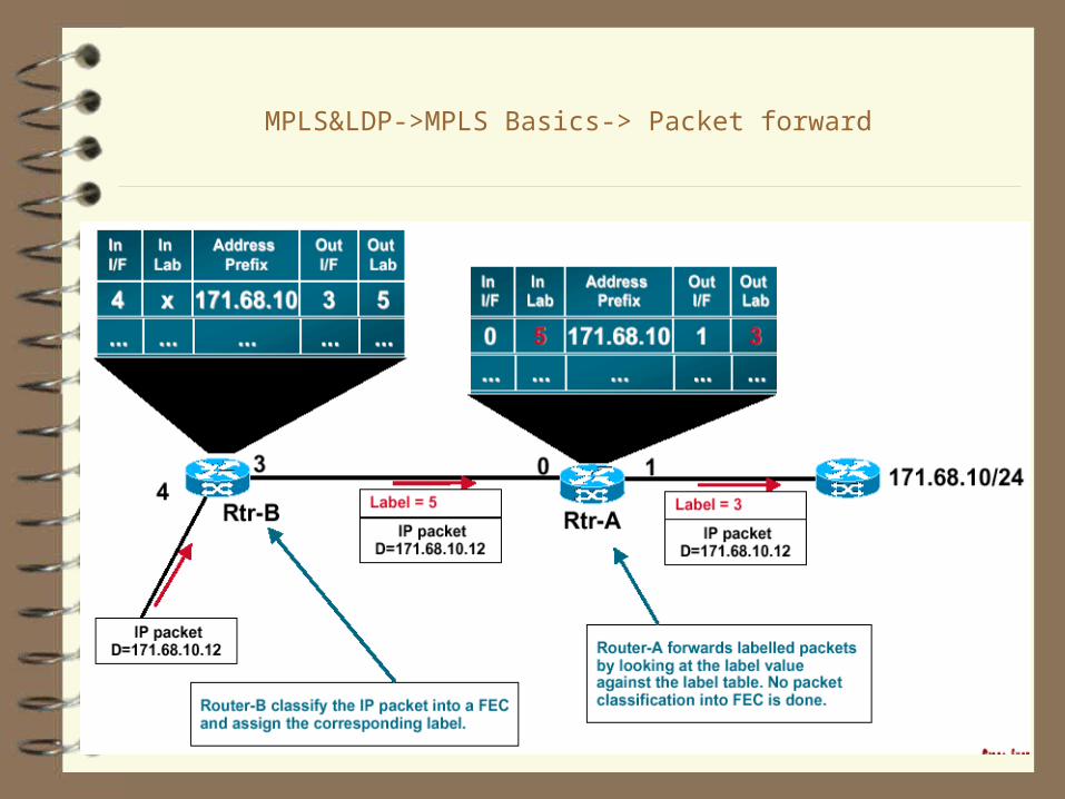
MPLS&LDP->MPLS Basics-> Packet forward

MPLS Network
R1
R2 R5
Access A1
Access A2
Access A3
IP backbone R6
R4
R3
Destination D
Desired route from Ax to DActual route from Ax to D
Traffic Engineering to override shortest path route
MPLS&LDP->MPLS Basics-> Packet forward

Terminology
• Label - a short fixed length identifier used to identify a FEC, usually of local significance
• FEC - Forwarding Equivalence Class represents set of packets with common cross core forwarding requirements
• LSR - Label Switched Router• LER - Label Edge Router• NHLFE - Next Hop Label Forwarding Entry• ILM - Incoming Label Map
Maps label to a set of NHLFE entries• LSP - Label Switched Path
Path through one or more LSRs at one level of hierarchy followed by packets in a particular FEC

Key concept in MPLS
• Seperation of IP router’s function into Forwarding and Control
• Forwarding - deals with how data packets are relayed between IP routers, uses label swapping.
• Control - consists of network layer routing protocols to distribute routing information between LSR’s and label binding procedures for converting this routing information into forwarding tables needed for Label Switching.

MPLS Advantages
1. Router can use any information in determining label assignment, not limited to packet header;
2. How to distribute labels may become more and more complicated, without any impact on the routers that merely forward labeled packets.
3. A label can be used to represent a pre-chosen route so that the identity of explicit route need not be carried with the packet.
4. Mutiprotocol: its techniques are applicable to ANY network layer protocol.

Label Based Forwarding
• At each LSR, forwarding is done by the single index lookup into the switching table using the packet’s MPLS label.
• The switching table is loaded a priori with a unique next-hop label, output port and queuing and scheduling rules.
• The establishment of mapping information is responsibility of control part - done using Label Distribution Protocols
MPLS MPLS PayloadLabel
SwitchingTable Next hop +
portQueuing and Scheduling
Output Ports
InputPorts
Label Stack
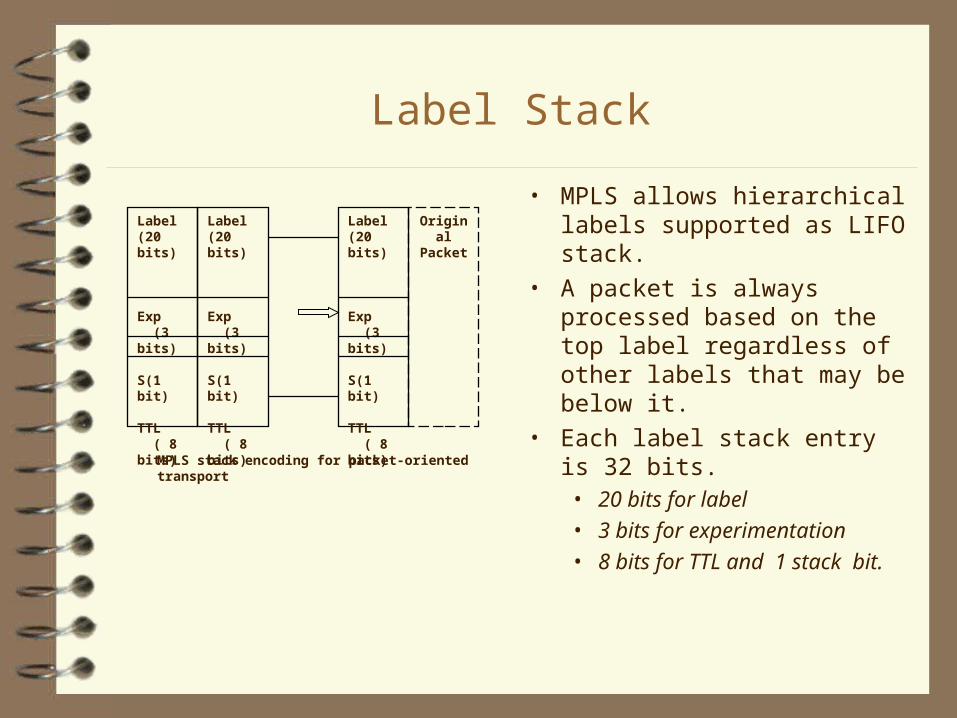
• MPLS allows hierarchical labels supported as LIFO stack.
• A packet is always processed based on the top label regardless of other labels that may be below it.
• Each label stack entry is 32 bits.• 20 bits for label • 3 bits for experimentation • 8 bits for TTL and 1 stack
bit.
Label (20 bits)
Exp (3 bits)
S(1 bit)
TTL ( 8 bits)
Label (20 bits)
Exp (3 bits)
S(1 bit)
TTL ( 8 bits)
Label (20 bits)
Exp (3 bits)
S(1 bit)
TTL ( 8 bits)
Original Packet
MPLS stack encoding for packet-oriented transport

Control in MPLS
• Consists of • Network Layer routing protocols to distribute routing
information between LSRs.• Label binding procedures to convert this routing
information into the forwarding tables needed for label switching
• QoS routing requires additional information about availability of resources in the network and QoS requirements of each flow.
• A signaling protocol is also needed for reserving needed resources along the a selected routee.g. CR-LDP, RSVP-TE

Label Assignment and Distribution
• The decision to bind a particular label L to a particular FEC F is made by the LSR which is DOWNSTREAM with respect to that binding. The downstream LSR then informs the upstream LSR of the binding.
• A label distribution protocol is a set of procedures by which one LSR informs another of the label/FEC bindings it has made.
• The label distribution protocol also encompasses any negotiations in which two label distribution peers need to engage in order to learn of each other's MPLS capabilities.
• THE ARCHITECTURE DOES NOT ASSUME THAT THERE IS ONLY A SINGLE LABEL DISTRIBUTION PROTOCOL.

Label Assignment Strategies
• Two LSRs must establish a bidirectional LDP session to exchange label binding information.
• Labels are always “downstream assigned”. • Label information flows in the direction opposite to
that of data packets
• Two modes of label distribution• Unsolicited Downstream - each LSR distributes
label bindings to its upstream LSRs (even if they haven’t explicity requested them).
• Downstream-on-demand - each LSR allows LSR upstream to explicitly request the label binding for a particular FEC.

MPLS&LDP->MPLS Basics->Labels
Ru Rd
Upstream LSR Downstream LSR
Agreement: "binding" label L to FEC F for packets moving from Ru to Rd.
So, L becomes Ru's "outgoing label" representing FEC F, and L becomes Rd's "incoming label" representing FEC F. Note that L is an arbitrary value whose binding to F is local to Ru and Rd.

Label Distribution Control
• Ordered Vs Independent• In Independent control, each LSR upon noting that
it recognizes a particular FEC makes an independent decision to bind a label to that FEC and to distribute the binding information to its label distribution peers.
• In Ordered control, an LSR only binds a label to a particular FEC if it is egress LSR for that FEC or if it has already received label binding for that FEC from its next hop for that FEC.
• For an LSP to be set up with specified set of properties, ordered control must be used.
E.g. FEC = Traffic pertaining to an address prefix

Whom to send label binding information?
• Each LSR must distribute label bindings for an address prefix(FEC) to its label distribution peers for that FEC, which are• IGP neighbors (local peers)• BGP neighbors(remote peers)• Tunnel’s transmit endpoint(remote peer)
• Basically all this is topology driven MPLS where, each LSR must,• bind one or more labels to address prefix that appears
in the routing table• for each such FEC use label distribution protocol to
distribute the bindings to its Label distribution peers
Label Distribution Protocols
• No hard and fast rules for choosing a Label distribution protocol
• Requirements from a Label Distribution protocol• establish and maintain label bindings• information to be transmitted reliably and label
distribution protocol messages pertaining to a particular FEC need to be transmitted in sequence
• Flow control• Capability to carry multiple label messages in a
single datagram
• BGP speakers use BGP to distribute labels among themselves while routes are being distributed.

Aggregation
• Procedure of binding a single label to a union of FECs which is itself an FEC and of applying that label to all the traffic in the union is known as “aggregation”• e.g. set of distinct address prefixes might have same
egress node. Please note that each address prefix forms an FEC and the union of those FECs is also an FEC.

Label Edge Router
• LER terminates and originates LSP’s and performs both label based forwarding and conventional NIF functions.
• Ingress LER - labels unlabelled packets and creates an initial MPLS frame by pushing one or more MPLS label entries.
• Egress LER - terminates LSP by popping the top MPLS stack entry.
Conventional IP ports
Output port, label, queuing and scheduling rules
Forwarding Table
LSP Table(s)
Packet Labeling
Packet classification
IP IP payloadheader
MPLS IP PacketLabel
Queuing and scheduling
Context
MPLS core ports
Ingress LER

Recap
• Packet processing based on the top level label regardless of the label underneath
• FECs can be• coarse grained consisting of all the packets with
same destination address • Allow the overall system of be scalable where it is
useful to handle large bundle of flows as a single class of traffic
• Help in rerouting in event of occurrence of a fault
• fine grained as in packets belonging to a particular application running between two hosts.
• Help in providing different QoS to different flows.

Recap Contd.
• Mapping of packets to an FEC done only once at the Ingress router upon entry into an MPLS domain
• Subsequent packets are forwarded strictly according to their labels
• label is removed by egress LSR• Each LSR maintains label to NHLFE mapping giving
a set of entries for each FEC. • Mapping can be changed for
• load balancing over multiple paths• rerouting from a failed path to an alternate path

Route Selection
• Method used for selecting the LSP for a particular FEC.• Hop by Hop is the same as topology driven.• Explicit Routing
• Explicit route need to be specified only at the time that labels are assigned and not with each IP packet, as in case of IP routing
• Tunneling • A router Ru takes explicit action to cause a particular packet
to be delivered another router Rd even though Ru and Rd are not consecutive routers on the hop-by-hop path for that packet and Rd is not the packet’s ultimate destination. This concept is called tunneling.
• Hop-by-Hop routed tunnel • Explicitly routed tunnel

LSP Tunnels
• Implement a tunnel as a LSP, and use label switching rather than network layer encapsulation to cause a packet to travel through the tunnel.
• Set of packets sent through the LSP tunnel constitutes a FEC and each LSR in the tunnel must assign a label to that FEC.
• If a tunnel from Ru to Rd, then• Ru is transmit endpoint of the tunnel• Rd is receive endpoint of the tunnel
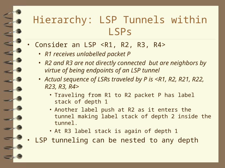
Hierarchy: LSP Tunnels within LSPs
• Consider an LSP <R1, R2, R3, R4>• R1 receives unlabelled packet P • R2 and R3 are not directly connected but are
neighbors by virtue of being endpoints of an LSP tunnel
• Actual sequence of LSRs traveled by P is <R1, R2, R21, R22, R23, R3, R4>
• Traveling from R1 to R2 packet P has label stack of depth 1
• Another label push at R2 as it enters the tunnel making label stack of depth 2 inside the tunnel.
• At R3 label stack is again of depth 1
• LSP tunneling can be nested to any depth

MPLS&LDP->MPLS Basics-> Tunnels&Hierarchy
R1 R2
R21 R22 R23
R3 R4 Level m-1
Level m
Fig. 2. Tunnels and Hierarchy

Traffic Engineering
Application of technology and scientific principles to the measurement, modeling, characterization and control of internet traffic. (Fundamentally, a control problem)
e.g mapping of traffic on IP network infrastructure
A network consists of :• Demand System (Traffic)• Constraint System (Interconnected N/W Elements)• Response System (N/W Protocols and Processes)

Traffic Engineering Process Model
• Performance Objective• Resource Oriented
• Efficient Link Utilization (Congestion Control)
• Traffic Oriented• Packet Loss• Delay / Delay Variation• Throughput
• Adaptive And Iterative Process
Formulation ofControl Policy
Observation ofNetwork State
Characterization oftraffic and network
state
Optimized?
ReviseControlPolicy
No
Optimized NetworkPerformance
No
Yes
Traffic Engineering Process Model

Response to Internet Growth by ISP’s
Capacity Expansion• DS3(44.736 Mbps) 1996
• OC-12c(622Mbps) 1997-98
• OC-48c(2.488Gbps) 1999
• OC-192c(9.953Gbps) over DWDM
• Traffic Engineering• Metric-Based Traffic Control till 1994-95
MPLS and Traffic Engineering
• MPLS supports origination connection control through explicit LSP’s
• Traffic trunk : Aggregation of traffic belonging to the same class.
• Mapping of traffic trunks on to the network topology is done by selection of routes for explicit LSP’s.
• LSP tunnels provide• rerouting in congested conditions• Flexible cost effective survivability• Provide statistics for Traffic Matrix• Parameterized resource allocation

Components of MPLS TE Model
• Network State Information Dissemination• Extending conventional IGP’s link state advertisements
• OSPF extensions implemented with Opaque LSAs• IS-IS extensions implemented using Type Length Values (TLVs)
• Traffic Engineering Database(TED) maintained by each LSR
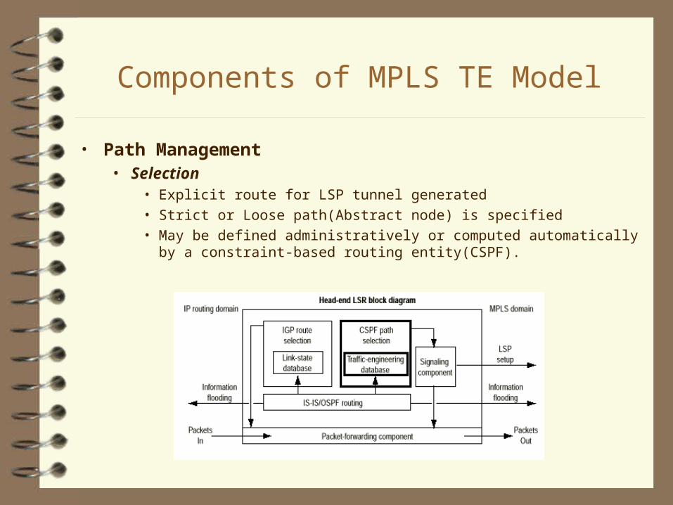
Components of MPLS TE Model
• Path Management• Selection
• Explicit route for LSP tunnel generated• Strict or Loose path(Abstract node) is specified• May be defined administratively or computed automatically by
a constraint-based routing entity(CSPF).

Components of MPLS TE Model
• Path Management• Instantiation or Placement
• Signaling Protocol which serves as an Label Distribution Protocol• Resource Reservation Protocol (RSVP) extensions• Constraint Routed Label Distribution Protocol (CR-LDP)
• Maintenance of LSP tunnelsSustain, Reroute or Terminate LSP tunnel

Components of MPLS TE Model
• Traffic Assignment• All aspects associated with allocation of traffic to
established LSP’s• Partitioning Function
• Network Management• Online management is
Non-deterministic• Offline management tools interfaced with MPLS to provide external feedback

Requirements for a Signaling Protocol
• Robustness
• Scalability
• LSP establishment/ teardown/maintenance
• Specification of QOS
• LSP Priority / Preemption
• Flexibility in Path Setup Options

U Message Message Message Mandatory Optional Type Length Id Parameters Parameters
1 5 16 32 variable variable
Format of LDP Messages
LDP Message Format
• Four classes of messages• Discovery messages to advertise the presence of LSRs
• Session messages to establish and maintain LDP sessions
• Advertisement messages to create, change and delete label mappings for FECs
• Notification messages to inform about faults

CR-LDP
• Extension of the LDP approach• Hard State Protocol• UDP used for peer discovery• TCP used for session, advertisement, notification, and LDP messages• Supports Diffserv and Operator configurable QOS classes• Failure reported using the reliable TCP

Extended RSVP
• Extension of the classical connectionless RSVP
• Path and Resv messages used with• Label_Request Object• Explicit_Route Object• Label Object
• Aggregation of flows to reduce state information in routers
• Soft State Control and scalability concerns

CR-LDP Vs RSVP
• Choice of Transport Protocol• UDP + TCP sessions Vs Raw IP
• Multipoint Support• Multipoint-to-Point : (Both support)
• Multicast (Point-to-Multipoint) : Yet to be addressed
• Scalability• Network Flows
• RSVP extensions for refreshing many LSPs in a single RSVP BUNDLE message and ability to indicate status quo rather than having to send the entire payload
• Others: CPU Utilization, Data Storage Requirements

CR-LDP Vs RSVP
• Link and Peer Failure • Both use HELLO extensions• RSVP uses the State Refresh Processing.• TCP failure implies re-establishment from
ingress• Policy Control
• RSVP messages carry policy objects• Security
• TCP is vulnerable to DOS attacks• RSVP has built in authentication and policy
control

MPLS&LDP-> LDP Procedures
• Security Considerations Some routers may implement security procedures which depend on the
network layer header being in a fixed place relative to the data link layer header. The MPLS generic encapsulation inserts a shim between the data link layer header and the network layer header. This may cause any such security procedures to fail.
An MPLS label has its meaning by virtue of an agreement between the LSR that puts the label in the label stack, and the LSR that interprets that label (the "label reader"). If labeled packets are accepted from untrusted sources, or if a particular incoming label is accepted from an LSR to which that label has not been distributed, then packets may be routed in an illegitimate manner.

LSP Rerouting
• Strictly specified route re-routed by the ingress node
• Loosely specified route :
• Refresh path for the next Hop of alternate route(RSVP)
• Make-before-Break using
• ’Modify’ flag in LABEL_REQUEST message (CR-LDP)
• Shared explicit filters may be used(RSVP)
• Problem of ‘Thrashing’ in unstable networks
• Loosely specified route may be ‘pinned’• Flagging the loose part of explicit route (CR-LDP)
• Record_Route Object is used in RSVP

LSP Modification and Protection
• Modification implies changing reservation parameters.
• Similar to rerouting
• Protection implies pre-programming of alternate paths
• Layer 2 protection transparent to the LSP is assumed
• Schemes for pre-programmed alternate paths from the ingress or intermediate nodes are under consideration.

MPLS QoS
• IP QoS can be based on:• Multifield IP header classification (up to 104 bits)
• Diffserv (DS field with 6 bits)
• MPLS performs classification and scheduling on the basis of 20 bit label and 3 bit experimental field
Per hop classification, queuing and scheduling
Port M
Queue
Queue
Queue
Queue
Port 1
Port N
Schedule

MPLS - QoS
• In MPLS, forwarding is independent of control and we have many different control planes .
• All control modules share a single QoS paradigm• same label lookup and 3 bits of experimentation determine
both the output queue and priority. • Unique to MPLS - same control mechanisms are invoked
regardless of which control plane assigned the labels.
• LER does multified classification to assign packets to LSPs with specific attributes(map EXP bits in the MPLS header)
• 3 bit E field => upto 8 different Diffserv code points will be available over a single tunnel. Work is in progress to define these code points.

Reliability in MPLS
• Current Internet has inherent survivability because of connectionless IP protocol.
• Loss of QoS is not a issue because the service is best-effort.
• In MPLS, Reliability is important because of support for integrated Services
• Fault Recovery• Centralized by a network Manager• Distributed control by having the LSRs automatically
initiate fault recovery procedures upon fault detection.

Requirements for Fault Recovery
• Fault Notification to all the affected LSRs• Search for an alternate path for the affected traffic• Rerouting to an alternate path• (Optional) redistribution of the network traffic to
ensure that capacity will be available to recover from subsequent faults

Notification
• Notification Message generated by the LSR downstream from where the fault is detected
• Notification message carries• type of error• Status TLV identifying
• failed link• cause of failure• affected FECs

Current Backbone Networks Protection
• Link layer protection (SONET/SDH)
• capable of service restoration within few tens of milliseconds• The scope of the protection is limited, has no visibility into higher layer operations
• Layer 3 protection • Routing protocol provide much greater flexibility• restoration time in the order of seconds to minutes

Motivation: MPLS-Based Recovery
• MPLS is the lowest layer with the knowledge of the entire network topology
• MPLS provide necessary traffic engineering capabilities• MPLS has desirable attributes when applied to the purpose of
recovery for connectionless networks• MPLS provide restoration times significantly shorter then the
convergence times of IP routing protocols
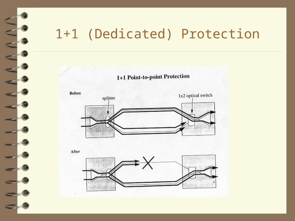
1+1 (Dedicated) Protection
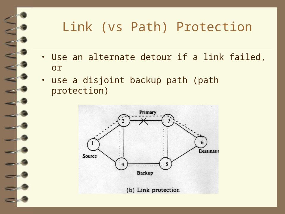
Link (vs Path) Protection
• Use an alternate detour if a link failed, or• use a disjoint backup path (path protection)

Mesh Network Protection

Non-Dedicated Protection
• 1:1 Protection 1:N Protection

Path Mapping
• 1-to-1 Protection recovery path that is only to be used to recover that specific
working paththe recovery path can carry pre-emptable/low-priority traffic
• 1-to-n Protection n working paths are protected using only one recovery path
As to backup bandwidth sharing, as long as the n working paths are disjoint (and hence at most one can fail at a time), their protection paths can share backup bandwidth on common links.
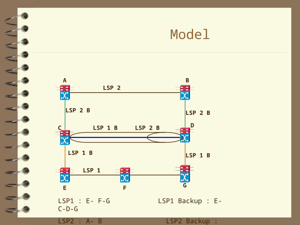
Model
BA
C
LSP 2
GFE
D
LSP 1
LSP 1 B LSP 1 B
LSP 2 B LSP 2 B
LSP 1 B LSP 2 B
LSP1 : E- F-G LSP1 Backup : E-C-D-G
LSP2 : A- B LSP2 Backup : A-C-D-B

Advantages & Disadvantages of Protection
• Simple and Quick: especailly if it uses 1+1• Do not require much extra process time, except to
signal (set up) the switches along the pre-determined backup path (1:1 or 1:N)
• Usually can only recover from single link fault (what if the pre-computed path fails?)
• Inefficient usage of resource
Restoration vs Protection
• Restoration the recovery path or path segments are created dynamically
after the detection of a fault on the working path. (the recovery path is not pre- computed)
• Protection Switching In contrast to retoration, the recovery path is pre- computed
(but may not be pre-established).

Restoration
• Path Restoration• Route can be computed after failure
• Link Restoration• Path is discovered at the end nodes of the failed link• More practical than path restoration
• Advantages & Disadvantages of Restoration• Usually can recover from multiplex element faults• More efficient usage of resource• Complex• Slow: require extra process time to setup path and reserve
resource

• Characteristic: Protection -- the resource are reserved before the failure, they may be not used; Restoration -- the resource are reserved and used after the failure
• Route: Protection -- predetermined; Restoration -- can be dynamically computed
• Resource Efficiency: Protection -- Low; Restoration – High
• Time used: Protection -- Short; Restoration -- Long• Reliability: Protection -- mainly for single fault;
Restoration -- can survive under multiplex faults• Implementation: Protection -- Simple; Restoration --
Complex
Comparison between Protection & Restoration

Definitions and Terminology
• Path Switch LSR (PSL) • The PSL is responsible for switching or replicating the
traffic between the working path and the recovery path• Normally chosen as the Ingress LSR or the nearest
upstream LSR to the failure (link or node). • Path Merge LSR (PML)
• The PML is responsible for receiving the recovery path traffic, and either merges the traffic back onto the working path, or, if it is itself the destination, passes the traffic on to the higher layer protocols
• Normally chosen as the Egress LSR

Definitions and Terminology
• Fault Indication Signal (FIS) A signal that indicates that a fault along a path has occurred. It
is relayed by each intermediate LSR to its upstream or downstream neighbor, until it reaches the PSL
• Fault Recovery Signal (FIS) A signal that indicates a fault along a working path has been
repaired.Like the FIS,it is relayed by each intermediate LSR to its upstream or downstream neighbor, until is reaches the PSL
Fault Detection
• Link/Path Failure detected by a link probing mechanism (hello liveness message )
between neighbor LSRsPath failures can also be detected by Src/Dest (time-out, NAK etc) or by the Dest if 1+1 path protection is used.
• Path Degraded path has connectivity, but that the quality of the connection is
unacceptable (e.g., high error bit rate, label mismatch or due to TTL errors). Need performance monitoring mechanisms.
• Link Degraded the link over which the working path is carried is performing below
an acceptable level

Scope of Recovery
• Local Repair• protect against a link or neighbor node fault and to
minimize the amount of time required for failure propagation
• Fast but not optimized• Global Repair
• the PSL is usually distant from the failure and needs to be notified by a FIS
• the recovery path can be made completely link and node disjoint with its working path
• slower than local repair
Post Recovery Operation
• When traffic is flowing on the recovery path, and the failure on the working path is repaired, one can
• Consider the recovery path as a new working path (Non-Revertive Mode)
• switch to the old working path (Revertive Mode)• switch to a more preferred working path
(make before break ----- RSVP TE Recovery)
MPLS-based Recovery Principles
• Configuration of Recovery • Default-recovery (No MPLS-based recovery enabled)• Recoverable (MPLS-based recovery enabled)
• Initiation of Path Setup • Pre-established• Pre Qualified• Established-on-Demand
• Initiation of Resource Allocation • Pre-reserved• Reserved-on-Demand

MPLS Recovery Cycle Model
Network Impairment Network Impairment
Start of Notification Start of Recovery Operation
Recovery Operation CompletePath Traffic Restored
Fault Detected
T1 Fault Detection Time T2 Hold-off Time
T3 Notification Time T4 Recovery Operation Time
T5 Traffic Restoration Time
T1 T2 T3 T4 T5 T

Main Comparison Criteria
• Recovery Time: the time required for a recovery path to be activated (and traffic flowing) after a fault
• Loss: Recovery schemes may introduce a certain amount of packet loss during switchover to a recovery path.
• Backup Capacity:The capacity will be dependent on the traffic characteristics of the network, the particular protection plan selection algorithms as well as the signaling and re-routing methods.
• Re-ordering: the action of putting traffic back on preferred paths might cause packet re-ordering
• State Overhead: As the number of recovery paths in a protection plan grows, the state required to maintain them also grows

MPLS Recovery Goals
• Using traffic engineering to optimal use of resources • Aim to facilitate restoration times that are sufficiently fast for the end user application• Aim to maximize network reliability and availability• Aim to be applicable for protection of traffic at various
granularities• for a portion of the traffic on an individual path• for all traffic on an individual path• for all traffic on a group of paths
• Be applicable for segments or an entire end-to-end path

Rerouting
• Recipient of Notification message depends on whether the recovery is done by link rerouting or edge-to-edge rerouting
• Link Rerouting• Alternate path is found between two LSRs on the ends of failed
link

Rerouting
• fast recovery • alternate path may be pre-established in the form of
another entry in NHLFE mapping for the label. Only for guaranteed services otherwise wasteful of resources
• For more efficient resource utilization, resource may not be reserved
• The notification message should check the availability of resources along the pre-established alternate path as it travels the upstream LSR
• dynamic creation of alternate path• Downstream LSR has QoS information, may select the
alternate path and send appropriate Label_Mapping message to reserve resources along the alternate path
Edge to Edge Rerouting
• More complex approach• Finds another link disjoint path from Ingress to
Egress LSR• Advantage of handling multiple link failures• Each effected FEC may have different
Ingress/Egress LSR pairs and must be rerouted individually• Hence the use of coarse grained FECs to minimize
the number of FECs to reroute.

Shared Backup LSP Restoration
• links on the backup path can be shared between different active paths
• Single link failure restoration is guaranteed• using only aggregate network usage information without
requiring per-LSP routing information for all current active LSPs • Aggregate information is obtainable by adding a few new
information elements to the link state advertisement of a link state routing protocol like OSPF or ISIS

Model (=Protection)
BA
C
LSP 2
GFE
D
LSP 1
LSP 1 B LSP 1 B
LSP 2 B LSP 2 B
LSP 1 B LSP 2 B
LSP1 : E- F-G LSP1 Backup : E-C-D-G
LSP2 : A- B LSP2 Backup : A-C-D-B

Fast Reroute (= Protection)
• Main Idea: reverse traffic at the point of failure of the protected LSP back
to the source switch, where the traffic flow can be redirected
• Objective:• provide a single failure protection with quick restoration
comparable to the order of milliseconds• Minimize the alternative path computation complexity
and signaling requirements • 1:1 protection and 1:N protection can be achieved

Fast Reroute Model
1:1 protection
LSR 1 LSR 3 LSR 5 LSR 7
LSR 2 LSR 4 LSR 6
13 35 57
755331
12
24 46
67
From LSR 1 to LSR 7 LSR1: PSL , LSR7 : PML
Working LSP: 13-35-57 alternative LSP: 53 –31-12-24-46-67

Fast Reroute Model
1:N protection
LSR 1 LSR 3 LSR 5 LSR 7
LSR 2 LSR 4 LSR 6
13 35 57
755331
12
24 46
67
LSR 8 LSR 9
10
15
203040
2457
4657
57
1257
1220
2420
4620
20
( Using Label Stack )
3157
4020

Restoration Shortcuts
Source LSR A LSR B LSR C
LSR D
Destination
LSR B setup a shortcut alternative LSP
Applied for Voice over IP service
Pros. and Cons.
• Path computation complexity is greatly reduced• both primary and alternative path computations can be
localized at a single switch • The amount of LSP setup signaling is minimized • presence of traffic on the alternative segment path can be
used as an FIS of the downstream primary path • Data packets need reordering during the path rerouting
process • Less resource efficient (total length protection)

RSVP Detour
• To achieve timely detour path setup, using pre-computed and pre- established detour path is essential for data traffic where packet loss is undesirable
• Detour decision must be made as close to the failure point as possible
• Ideal detour mechanism is to protect the entire LSP by establishing detour paths throughout the LSP
• To minimize the path computation overhead, it is desirable for the detour paths to merge back to the main LSP as soon as possible
• only protect unidirectional LSP

RSVP Detour Model
Activate RSVP Tunnel (LSP)
RSVP Detour (LSP)
Ingress EgressLSR 1 LSR 3LSR 2
detour ( Ingress,LSR2 )

RSVP Extension
Two new objects are defined to support LSP fast-reroute• FAST_REROUTE object
• Setup (Holding) Priority: The priority of the detour with respect to taking(holding) resources
• Hop – limit: The maximum number of extra hops the detour is allowed to take
• Bandwidth • DETOUR object
• Source ID : IPv4 address identifying the beginning point of detour• Downstream Node ID :IP address identifying the downstream node
that source is trying to avoid
Make before break
• In general, it is highly desirable not to disrupt traffic, or adversely impact network operations while TE tunnel rerouting is in progress.
• This adaptive and smooth rerouting requirement necessitates establishing a new LSP tunnel and transferring traffic from the old LSP tunnel onto it before tearing down the old LSP tunnel
• The principle (implemented by RSVP Tunnel) applies not only in the case of failure but also when better routes are available than the existing ones.

Loop Prevention in MPLS
• Three levels of control • Loop survival
• allows forming of loop but looping packets does not impact transmission of non-looping packets. A node capable of TTL decrement has this capability.
• Loop detection• allows LSP to form a loop but detects and disconnects
in a short time, e.g. using LDP
• Loop prevention• most rigorous form of control

Immediate Consequences of MPLS
• Efficient transit core network• Improved economy of scale• Better utilization of Network• Fast recovery from faults

References
• Framework for MPLS-based recovery Vishal Sharma, Ben-Mack Crane,
<Draft-ietf-mpls-recovery-framework-03> , July 2001• Extensions to RSVP-TE for MPLS Path Protection Ken Owens, Vishal Sharma <Draft-chang-mpls-path-protection-02>, July 2001 • Shared Backup Label Switched Path Restoration Sriganesh Kini Murali Kodialam <Draft-
kini-restoration-shared-backup-01>, May 2001 • A Method for Setting an Alternative Label Switched Paths to Handle Fast Reroute Dimitry Haskin ,
Ram Krishnan <Draft-haskin-mpls-fast-reroute-05>, November 2000 • A Method for MPLS LSP Fast-Reroute Using RSVP Detours Der-Hwa Gan,
<Draft-gan-fast-reroute-00 > April 10, 2001• MPLS RSVP-TE Interoperability for Local Protection/Fast Reroute Alia Atlas ,Curtis Villamizar
<Draft-atlas-rsvp-local-protect-interop-01>, July 2001 • “ A heuristic approach to service restoration in MPLS networks,” in proc. Of the 2001 IEEE
International Conference on Communications (ICC), Helsinki, Finland, June 2001
References Web Sites
www.mplsrc.com
www.ietf.org/internet-drafts
www.datacon.co.uk
IEEE Communications Magazine – December 1999
MPLS and Traffic Engineering in IP Networks - discusses the applications of MPLS to traffic engineering in IP networks. By Daniel O. Awduche of UUNET, MCI WorldCom
MPLS Advantages for Traffic Engineering - discusses the architectural aspects of MPLS which enable it to address IP traffic management. By George Swallow.
Traffic Engineering Standards in IP Networks Using MPLS - overview of the various approaches for label distribution.
MPLS and the evolving Internet Architecture – By Toni Lee, Procket Networks, Inc.
Issues on Loop Prevention in MPLS Networks - provides an overview of various methods underdevelopment for preventing LSP loops. By Yoshihiro Ohba.
Reliable Services in MPLS - examines distributed methods for fast fault recovery using modified LDP messages. By Thomas M. Chen and Tae H. Oh
IEEE Communications Magazine - January 2000
MPLS : The Magic behind the Myths - By Grenville Armitage, Bell Labs Research Silicon Valley, Lucent Technologies

References
IETF Drafts
draft-ietf-mpls-arch.txt
draft-ietf-mpls-rsvp-lsp-tunnel.txt
Others
IP Traffic Engineering for Carrier Networks: Using Constraint-BasedRouting to Deliver New Services - White Paper on constraint-based routing. By Nortel Networks
Traffic Engineering for the New Public Network - An overview of the present and future of traffic engineering. By Juniper Networks
MPLS Traffic Engineering : A Choice of Signaling Protocols - White paper comparing RSVP and CR-LDP for label path distribution. By Data Connection
RSVP Signaling Extensions for MPLS Traffic Engineering - Describes extensions to RSVP to automate the establishment of LSP's across service provider networks. By Juniper Networks
• DiffServ and MPLS: A quality choice - Data Communications article comparing MPLS and DiffServ for use in building networks capable of delivering QoS
Daniel Obi Awduche's home page - Collection of papers and drafts on traffic engineering, optical networking and MPLS written by the manager of advanced technology for UUNET
Deploying MPLS Traffic Engineering - An overview of the process for deploying traffic engineering using MPLS. By Juniper Networks