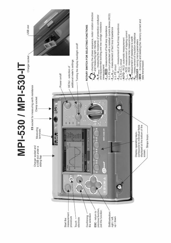
mpi-530 / 530-it user manual - cdn.sonel.com
TRANSCRIPT

2

USER MANUAL
METER FOR ELECTRICAL INSTALLATION
PARAMETERS
MPI-530 MPI-530-IT
SONEL S.A.
Wokulskiego 11
58-100 Świdnica
Poland
Version 2.03 24.08.2021

MPI-530 MPI-530-IT – USER MANUAL 2
MPI-530 / MPI-530-IT meter is a modern, easy in use and safe measuring device. Please acquaint yourself with this manual in order to avoid measuring errors and prevent possible problems in opera-tion of the meter.
MPI-530 MPI-530-IT – USER MANUAL 3
CONTENTS
1 Safety ................................................................................................................ 6
2 Menu .................................................................................................................. 7 2.1 Wireless transmission .............................................................................................. 8 2.2 Measurement Settings ............................................................................................. 8
2.2.1 Earthing system, voltage and frequency ........................................................................... 8 2.2.2 Main result of fault loop impedance measurement ............................................................ 9 2.2.3 Measurement settings ..................................................................................................... 10 2.2.4 RCD AUTO measurement mode ..................................................................................... 10 2.2.5 Cell autoincrementing ..................................................................................................... 11 2.2.6 Resistivity measurement settings .................................................................................... 11 2.2.7 Calibration of C-3 clamps ................................................................................................ 12 2.2.8 Setting limits ................................................................................................................... 12
2.3 Meter Settings ........................................................................................................ 13 2.3.1 LCD contrast ................................................................................................................... 13 2.3.2 LCD Backlight ................................................................................................................. 14 2.3.3 Automatic shut-off (Auto-OFF) ........................................................................................ 14 2.3.4 Date and time.................................................................................................................. 15 2.3.5 Key sounds ..................................................................................................................... 15 2.3.6 Factory (default) settings................................................................................................. 16 2.3.7 Software update .............................................................................................................. 16 2.3.8 Wireless communication ................................................................................................. 16
2.4 Language selection ................................................................................................ 17 2.5 Information about manufacturer ............................................................................. 17
3 Measurements ................................................................................................ 18 3.1 Diagnostics performed by the meter - limits ........................................................... 18 3.2 Measurement of alternating voltage and frequency ............................................... 18 3.3 Checking the correctness of PE (protective earth) connections ............................ 19 3.4 Measurement of fault loop parameters .................................................................. 20
3.4.1 Measurement of fault loop parameters in the L-N and L-L circuits ................................... 20 3.4.2 Measurement of fault loop parameters in the L-PE circuit ............................................... 23 3.4.3 Measurement of fault loop impedance in L-PE circuit protected with a residual current
device (RCD) .................................................................................................................. 25 3.4.4 Prospective short-circuit current ...................................................................................... 26 3.4.5 Measurements in IT networks .......................................................................... 27
3.5 Measurement of resistance to earth ....................................................................... 28 3.5.1 Measurement of resistance to earth using 3p method ..................................................... 28 3.5.2 Measurement of resistance to earth using 4p method ..................................................... 32 3.5.3 Measurement of resistance to earth using 3p + clamps method ...................................... 36 3.5.4 Measurement of resistance to earth using double clamp method .................................... 40 3.5.5 Measuring soil resistivity ................................................................................................. 43
3.6 Measurement of RCD parameters ......................................................................... 47 3.6.1 Measurement of RCD disconnection current ................................................................... 47 3.6.2 Measurement of RCD disconnection time ....................................................................... 50 3.6.3 Automatic measurement of RCD parameters .................................................................. 52 3.6.4 Measurements in IT networks .......................................................................... 59
3.7 Measurement of insulation resistance.................................................................... 60 3.7.1 Double-lead measurement .............................................................................................. 60 3.7.2 Measurements by means of leads with UNI-Schuko outlet plug (WS-03 and WS-04) ..... 63
MPI-530 MPI-530-IT – USER MANUAL 4
3.7.3 Measurements with AutoISO-1000c adapter .................................................................. 66 3.8 Low-voltage measurement of resistance ................................................................ 70
3.8.1 Measurement of resistance of protective conductors and equipotential bonding with ±200 mA current ...................................................................................................................... 70
3.8.2 Measurement of resistance ............................................................................................ 73 3.8.3 Compensation of test leads resistance ........................................................................... 74
3.9 Checking sequence of phases ............................................................................... 75 3.10 Checking the motor rotation direction ..................................................................... 77 3.11 Light measurements ............................................................................................... 78 3.12 Recorder. Measurement and recording of current, voltage, cosφ, PF factor,
harmonics and THD ................................................................................................ 80
4 Memory of measurement results ................................................................. 84 4.1 Structure of the Memory ......................................................................................... 84
4.1.1 The appearance of main windows in the measurement recording mode ......................... 85 4.2 Storing the measurement results data in the memory ............................................ 87
4.2.1 Entering the results without extending the memory structure .......................................... 87 4.2.2 Extending the memory structure ..................................................................................... 88
4.3 Browsing and editing the memory .......................................................................... 93 4.4 Browsing the recorder memory .............................................................................. 95 4.5 Deleting memory data ............................................................................................ 98
5 Data transmission ....................................................................................... 100 5.1 Set of accessories to connect the meter to a PC ................................................. 100 5.2 Data transmission through USB port .................................................................... 100 5.3 Connecting to Bluetooth mini-keyboard................................................................ 100
5.3.1 Manual connection ....................................................................................................... 100 5.3.2 Automatic connection ................................................................................................... 102
5.4 Data transmission using Bluetooth module .......................................................... 102 5.5 Read-out and change of PIN code for Bluetooth connections.............................. 103
6 Power supply of the meter ......................................................................... 105 6.1 Monitoring the power supply voltage .................................................................... 105 6.2 Replacing batteries (rechargeable batteries) ....................................................... 105 6.3 Charging rechargeable batteries .......................................................................... 106 6.4 General principles for using Ni-MH rechargeable batteries .................................. 107
7 Cleaning and maintenance ......................................................................... 108
8 Storage ......................................................................................................... 108
9 Dismantling and utilisation ........................................................................ 109
10 Technical specifications ............................................................................. 109 10.1 Basic data ............................................................................................................. 109 10.2 Other technical data ............................................................................................. 119 10.3 Additional data ...................................................................................................... 119
10.3.1 Additional uncertainties according to IEC 61557-2 (RISO) ............................................. 119 10.3.2 Additional uncertainties according to IEC 61557-3 (Z) .................................................. 120 10.3.3 Additional uncertainties according to IEC 61557-4 (R ±200 mA) .................................. 120 10.3.4 Additional uncertainties of earth resistance measurement (RE) .................................... 120 10.3.5 Additional uncertainties according to IEC 61557-6 (RCD) ............................................ 121
10.4 List of reference standards ................................................................................... 121
MPI-530 MPI-530-IT – USER MANUAL 5
11 Accessories .................................................................................................. 122 11.1 Standard accessories .......................................................................................... 122 11.2 Optional accessories ............................................................................................ 123
11.2.1 Clamps C-3 ................................................................................................................... 126 11.2.2 Clamps C-6 ................................................................................................................... 127 11.2.3 Clamps F-1, F-2, F-3 ..................................................................................................... 128 11.2.4 Clamps N-1 ................................................................................................................... 129
12 Positions of the meter’s cover .................................................................... 130
13 Manufacturer ................................................................................................ 130
14 Laboratory services ..................................................................................... 131
MPI-530 MPI-530-IT – USER MANUAL 6
The icon with the meter name is placed next to sections of the text that refer to specific fea-
tures of the device. All other parts of the text relate to all types of the instrument.
1 Safety
MPI-530 / MPI-530-IT meter is designed for performing check tests of protection against electric shock in AC mains systems. The meter is used for making measurements and providing results to determine safety of electrical installations. Therefore, in order to provide conditions for correct opera-tion and accuracy of obtained results, the following recommendations must be observed:
Before you proceed to operate the meter, acquaint yourself thoroughly with the present manual and observe the safety regulations and specifications provided by the producer.
Any application that differs from those specified in the present manual may result in a damage to the device and constitute a source of danger for the user.
MPI-530 / MPI-530-IT meters must be operated only by appropriately qualified personnel with rel-evant certificates authorising the personnel to perform works on electric systems. Operating the meter by unauthorised personnel may result in damage to the device and constitute a source of danger for the user.
Using this manual does not exclude the need to comply with occupational health and safety regu-lations and with other relevant fire regulations required during the performance of a particular type of work. Before starting the work with the device in special environments, e.g. potentially fire-risk/explosive environment, it is necessary to consult it with the person responsible for health and safety.
It is unacceptable to operate:
a damaged meter which is completely or partially out of order,
a meter with damaged insulation,
a meter stored for an excessive period of time in disadvantageous conditions (e.g. excessive humidity). If the meter has been transferred from a cool to a warm environment with a high level of relative humidity, do not start measurements until the meter is warmed up to the am-bient temperature (approximately 30 minutes).
Displayed BAT! symbol indicates insufficient voltage of power supply and the need to charge the accumulator or replace batteries. All measurements except voltage measurements for Z and RCD functions are blocked.
Battery spill and damage to the meter may occur if discharged batteries are left in the meter.
Before measurements may commence, make sure the leads are connected to the appropriate measurement sockets.
Do not operate a meter with an open or incorrectly closed battery (accumulator) compartment or power it from other sources than those specified in the present manual.
RISO meter inputs are electronically protected against overloads (caused by e.g. connecting the meter to a live circuit) up to 440V rms for 60 seconds.
Repairs may be performed only by an authorised service point.
ATTENTION!
Only standard and additional accessories for a given device should be used, as listed
in the "Equipment" section. Using other accessories may cause damage to measuring
terminals, introduce additional measurement uncertainty and create a risk for the user.
Note:
Due to continuous development of the meter’s software, the actual appearance of the
display, in case of some of the functions, may slightly differ from the display presented
in this operating manual.
MPI-530 MPI-530-IT – USER MANUAL 7
Note:
An attempt to install drivers in 64-bit Windows 8 may result in displaying "In-
stallation failed" message.
Cause: Windows 8 by default blocks drivers without a digital signature.
Solution: Disable the driver signature enforcement in Windows.
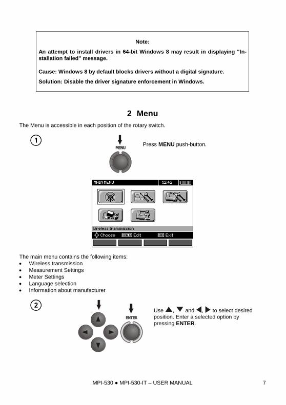
2 Menu
The Menu is accessible in each position of the rotary switch.
Press MENU push-button.
The main menu contains the following items:
Wireless transmission
Measurement Settings
Meter Settings
Language selection
Information about manufacturer
Use , and , to select desired
position. Enter a selected option by
pressing ENTER.
MPI-530 MPI-530-IT – USER MANUAL 8
2.1 Wireless transmission
See section 5.3.
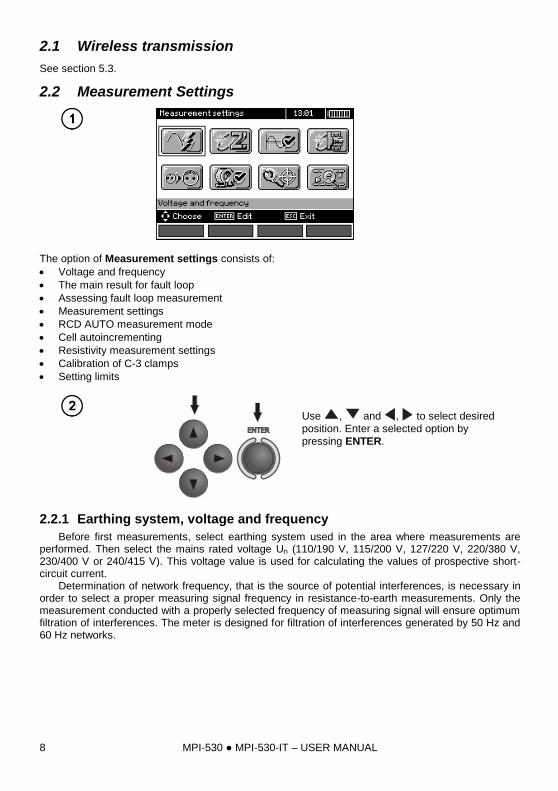
2.2 Measurement Settings
The option of Measurement settings consists of:
Voltage and frequency
The main result for fault loop
Assessing fault loop measurement
Measurement settings
RCD AUTO measurement mode
Cell autoincrementing
Resistivity measurement settings
Calibration of C-3 clamps
Setting limits
Use , and , to select desired
position. Enter a selected option by
pressing ENTER.
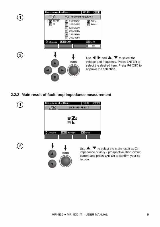
2.2.1 Earthing system, voltage and frequency
Before first measurements, select earthing system used in the area where measurements are performed. Then select the mains rated voltage Un (110/190 V, 115/200 V, 127/220 V, 220/380 V, 230/400 V or 240/415 V). This voltage value is used for calculating the values of prospective short-circuit current.
Determination of network frequency, that is the source of potential interferences, is necessary in order to select a proper measuring signal frequency in resistance-to-earth measurements. Only the measurement conducted with a properly selected frequency of measuring signal will ensure optimum filtration of interferences. The meter is designed for filtration of interferences generated by 50 Hz and 60 Hz networks.
MPI-530 MPI-530-IT – USER MANUAL 9
Use , and , to select the
voltage and frequency. Press ENTER to
select the desired item. Press F4 (OK) to approve the selection.
2.2.2 Main result of fault loop impedance measurement
Use , to select the main result as ZS impedance or as Ik - prospective short-circuit
current and press ENTER to confirm your se-lection.
MPI-530 MPI-530-IT – USER MANUAL 10
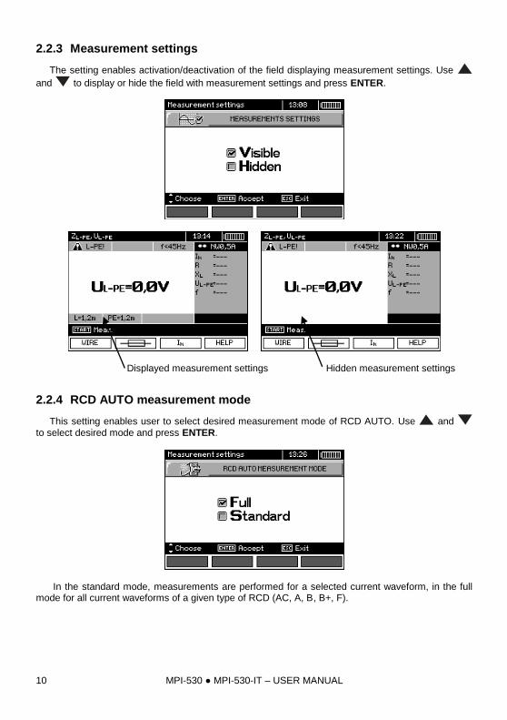
2.2.3 Measurement settings
The setting enables activation/deactivation of the field displaying measurement settings. Use
and to display or hide the field with measurement settings and press ENTER.
Displayed measurement settings Hidden measurement settings
2.2.4 RCD AUTO measurement mode
This setting enables user to select desired measurement mode of RCD AUTO. Use and
to select desired mode and press ENTER.
In the standard mode, measurements are performed for a selected current waveform, in the full mode for all current waveforms of a given type of RCD (AC, A, B, B+, F).
MPI-530 MPI-530-IT – USER MANUAL 11
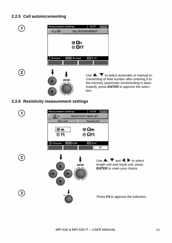
2.2.5 Cell autoincrementing
Use , to select automatic or manual in-crementing of field number after entering it to the memory (automatic incrementing is deac-
tivated), press ENTER to approve the selec-tion.
2.2.6 Resistivity measurement settings
Use , and , to select
length unit and result unit, press
ENTER to mark your choice.
Press F4 to approve the selection.
MPI-530 MPI-530-IT – USER MANUAL 12
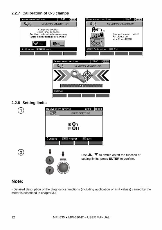
2.2.7 Calibration of C-3 clamps
2.2.8 Setting limits
Use , to switch on/off the function of
setting limits, press ENTER to confirm.
Note:
- Detailed description of the diagnostics functions (including application of limit values) carried by the meter is described in chapter 3.1.
MPI-530 MPI-530-IT – USER MANUAL 13
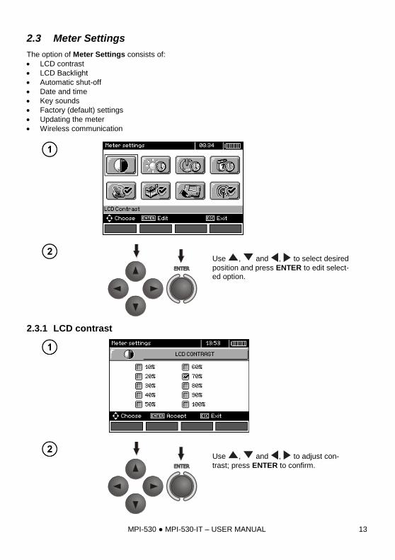
2.3 Meter Settings
The option of Meter Settings consists of:
LCD contrast
LCD Backlight
Automatic shut-off
Date and time
Key sounds
Factory (default) settings
Updating the meter
Wireless communication
Use , and , to select desired
position and press ENTER to edit select-ed option.
2.3.1 LCD contrast
Use , and , to adjust con-
trast; press ENTER to confirm.
MPI-530 MPI-530-IT – USER MANUAL 14
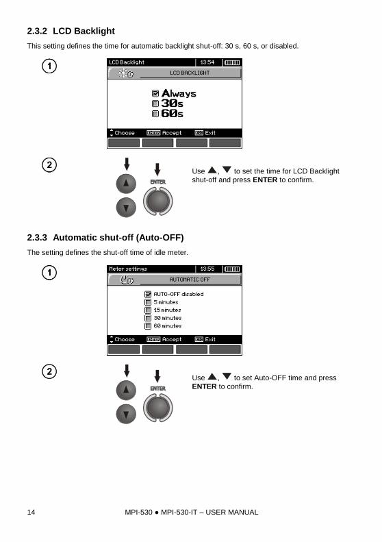
2.3.2 LCD Backlight
This setting defines the time for automatic backlight shut-off: 30 s, 60 s, or disabled.
Use , to set the time for LCD Backlight
shut-off and press ENTER to confirm.
2.3.3 Automatic shut-off (Auto-OFF)
The setting defines the shut-off time of idle meter.
Use , to set Auto-OFF time and press
ENTER to confirm.
MPI-530 MPI-530-IT – USER MANUAL 15
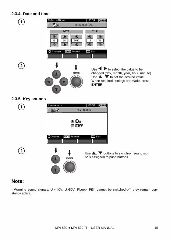
2.3.4 Date and time
Use , to select the value to be changed (day, month, year, hour, minute)
Use , to set the desired value. When required settings are made, press
ENTER.
2.3.5 Key sounds
Use , buttons to switch-off sound sig-nals assigned to push buttons.
Note: - Warning sound signals: U>440V, U>50V, Rbeep, PE!, cannot be switched-off, they remain con-stantly active.
MPI-530 MPI-530-IT – USER MANUAL 16
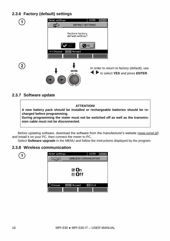
2.3.6 Factory (default) settings
In order to return to factory (default), use
, to select YES and press ENTER.
2.3.7 Software update
ATTENTION!
A new battery pack should be installed or rechargeable batteries should be re-
charged before programming.
During programming the meter must not be switched off as well as the transmis-
sion cable must not be disconnected.
Before updating software, download the software from the manufacturer’s website (www.sonel.pl)
and install it on your PC, then connect the meter to PC.
Select Software upgrade in the MENU and follow the instructions displayed by the program.
2.3.8 Wireless communication
MPI-530 MPI-530-IT – USER MANUAL 17
Use , to select the wireless communi-
cation ON/OF and press ENTER to confirm.
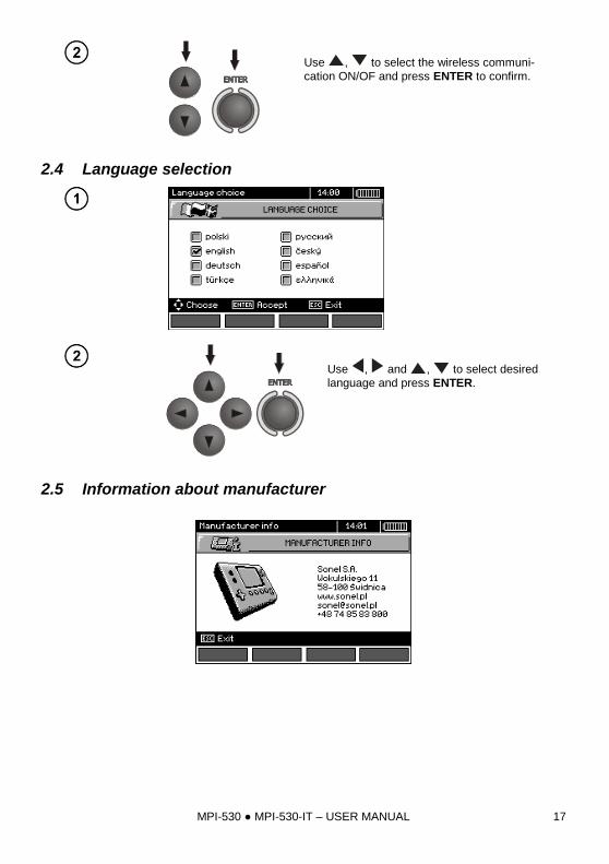
2.4 Language selection
Use , and , to select desired
language and press ENTER.
2.5 Information about manufacturer
MPI-530 MPI-530-IT – USER MANUAL 18
3 Measurements
Note: - A progress bar is displayed during long measurements. - The content of this chapter should be thoroughly familiarized with since it describes the meter circuits, the methods of measurements and basic principles concerning interpretation of measurement results. - Result of the latest measurement is remembered by the meter until a next measurement is started or measurement settings are changed or the measuring function is changed by means of the rotary switch or the meter is switched off. It is displayed for 20 s. Then it may be recalled by pressing
ENTER.
WARNING:
During measurements (fault loop, RCD), do not touch earthed and accessible parts of the
tested electrical installation.
WARNING:
During a measurement, switching of the range switch is forbidden because it may damage
the meter and pose a threat to the user.
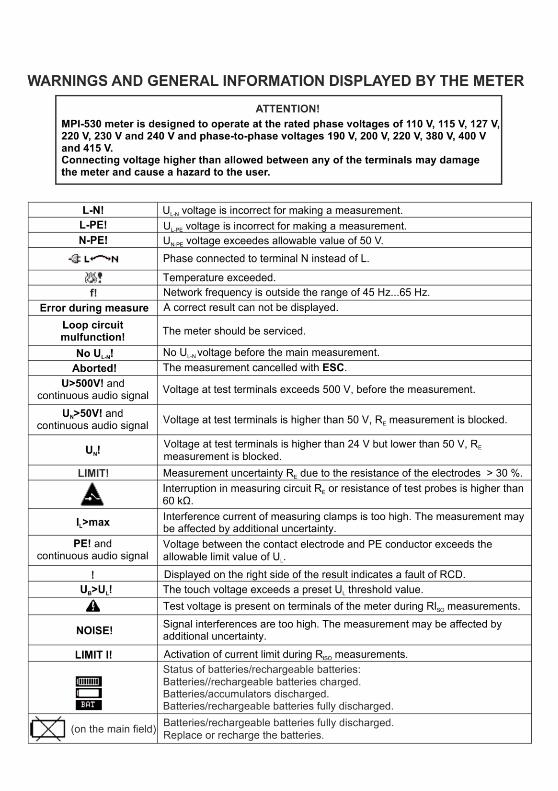
3.1 Diagnostics performed by the meter - limits
The meter is able to assess whether the measurement result is within acceptable limits for the selected safety device or the limit value. The user may set a limit, i.e. maximum or minimum value, which should not be exceeded by the result. It is possible for all measurement functions except RCD measurements for which limits are set and permanently active and for the recorder function. For measurements of insulation resistance and light, the set limit is the minimum value, whereas for the following measurements: fault loop impedance, earth resistance, resistance of protective conductors and equipotential bonding - it is the maximum value. The limits are activated globally in the main menu (Section 2.2.9). When the function of setting limits is activated, the display, in its upper right corner, shows the symbols with the following mean-ing:
- : the result is correct, it is within the set limits,
- : the result is incorrect, it is outside the set limits, - : the correctness of the result cannot be assessed: this symbol is displayed, when for example the result is not available (e.g. measurement in progress, or no measurement has been performed) The method for setting limits is described in the chapters describing the measurement data. It should be noted that for the fault loop the limit is determined indirectly by selecting a suitable overcur-rent protection for which standard limits are assigned.
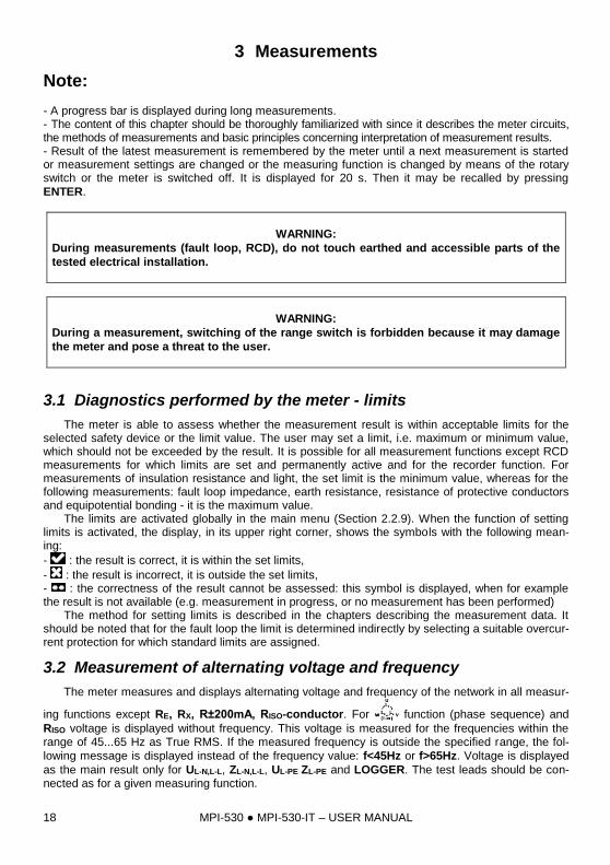
3.2 Measurement of alternating voltage and frequency
The meter measures and displays alternating voltage and frequency of the network in all measur-
ing functions except RE, RX, R±200mA, RISO-conductor. For function (phase sequence) and
RISO voltage is displayed without frequency. This voltage is measured for the frequencies within the range of 45...65 Hz as True RMS. If the measured frequency is outside the specified range, the fol-
lowing message is displayed instead of the frequency value: f<45Hz or f>65Hz. Voltage is displayed
as the main result only for UL-N,L-L, ZL-N,L-L, UL-PE ZL-PE and LOGGER. The test leads should be con-nected as for a given measuring function.
MPI-530 MPI-530-IT – USER MANUAL 19
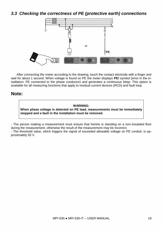
3.3 Checking the correctness of PE (protective earth) connections
After connecting the meter according to the drawing, touch the contact electrode with a finger and
wait for about 1 second. When voltage is found on PE the meter displays PE! symbol (error in the in-stallation; PE connected to the phase conductor) and generates a continuous beep. This option is available for all measuring functions that apply to residual current devices (RCD) and fault loop.
Note:
WARNING:
When phase voltage is detected on PE lead, measurements must be immediately
stopped and a fault in the installation must be removed.
- The person making a measurement must ensure that he/she is standing on a non-insulated floor during the measurement; otherwise the result of the measurement may be incorrect. - The threshold value, which triggers the signal of exceeded allowable voltage on PE conduit, is ap-proximately 50 V.
MPI-530 MPI-530-IT – USER MANUAL 20
3.4 Measurement of fault loop parameters
If there are residual current devices in the network tested, they should be by-
passed by bridging for the period of impedance measurement. However, it
should be remembered that the tested circuit is modified in this way and the ob-
tained results may slightly differ from the actual results.
After completing measurements, always remove modifications introduced to the
tested system for the period of measurements and check the operation of the re-
sidual current switch.
The above remark does not apply to measurements of fault loop impedance with
the use of ZL-PE RCD function.
Measurements of fault loop impedance performed downstream of inverters are
ineffective and their results are unreliable. This is due to the instability of internal
impedance in inverter circuits during its operation. The measurements of fault
loop impedance should not be performed directly downstream of inverters.
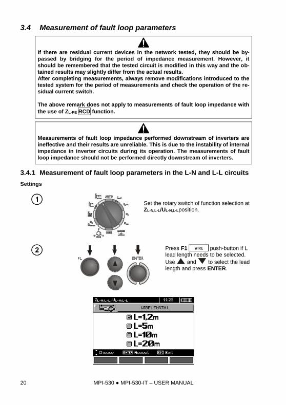
3.4.1 Measurement of fault loop parameters in the L-N and L-L circuits
Settings
Set the rotary switch of function selection at
ZL-N,L-L/UL-N,L-Lposition.
Press F1 push-button if L
lead length needs to be selected.
Use and to select the lead
length and press ENTER.
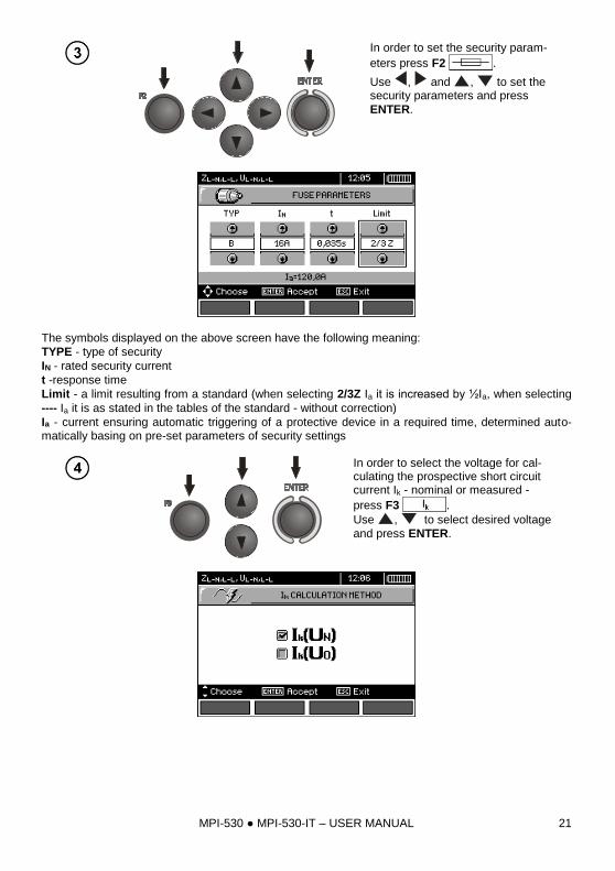
MPI-530 MPI-530-IT – USER MANUAL 21
In order to set the security param-
eters press F2 .
Use , and , to set the security parameters and press
ENTER.
The symbols displayed on the above screen have the following meaning:
TYPE - type of security
IN - rated security current
t -response time
Limit - a limit resulting from a standard (when selecting 2/3Z Ia it is increased by ½Ia, when selecting
---- Ia it is as stated in the tables of the standard - without correction)
Ia - current ensuring automatic triggering of a protective device in a required time, determined auto-matically basing on pre-set parameters of security settings
In order to select the voltage for cal-culating the prospective short circuit current Ik - nominal or measured -
press F3 .
Use , to select desired voltage
and press ENTER.
MPI-530 MPI-530-IT – USER MANUAL 22
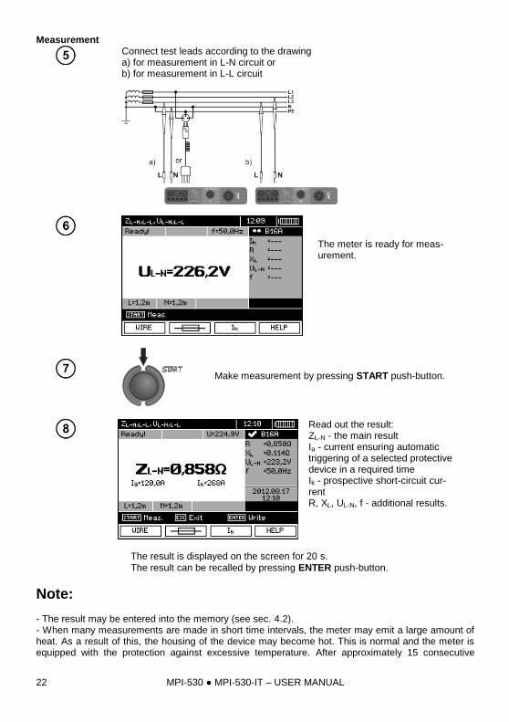
Measurement
Connect test leads according to the drawing a) for measurement in L-N circuit or b) for measurement in L-L circuit
The meter is ready for meas-urement.
Make measurement by pressing START push-button.
Read out the result: ZL-N - the main result Ia - current ensuring automatic triggering of a selected protective device in a required time Ik - prospective short-circuit cur-rent R, XL, UL-N, f - additional results.
The result is displayed on the screen for 20 s.
The result can be recalled by pressing ENTER push-button.
Note:
- The result may be entered into the memory (see sec. 4.2). - When many measurements are made in short time intervals, the meter may emit a large amount of heat. As a result of this, the housing of the device may become hot. This is normal and the meter is equipped with the protection against excessive temperature. After approximately 15 consecutive
MPI-530 MPI-530-IT – USER MANUAL 23
measurements of short circuit loop, wait until the instrument cools down. This limitation results from the high current measurement and multi-functionality of the meter. - Minimum interval between successive measurements is 5 seconds. This minimum interval require-
ment is controlled by the meter. The next measurement may be performed only when READY! mes-sage appears on the screen. Until the message is displayed - the meter prevents any measurements.
Additional information displayed by the meter
READY! The meter is ready for measurement.
L-N! UL-N voltage is incorrect for making a measurement.
L-PE! UL-PE voltage is incorrect for making a measurement.
N-PE! UN-PE voltage exceeds allowable value of 50V.
Phase connected to N terminal instead of L terminal (for example, exchange of L and N in the mains socket).
Temperature exceeded.
f! Network frequency is outside the range of 45 Hz ...65 Hz.
Error during mea-
surement Correct result cannot be displayed.
Loop circuit mal-
function! The meter should be serviced.
No UL-N! Lack of UL-N voltage before the main measurement.
U>500 V! and con-tinuous audio signal
Before measurement, voltage at test terminals exceeds 500 V.
LIMIT Too low value of the prospective short circuit current Ik for the pre-set security and time of its triggering.
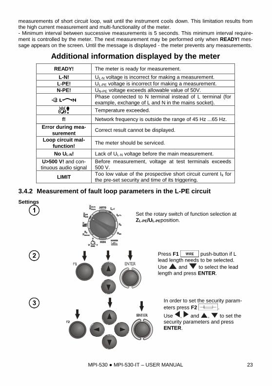
3.4.2 Measurement of fault loop parameters in the L-PE circuit
Settings
Set the rotary switch of function selection at
ZL-PE/UL-PEposition.
Press F1 push-button if L
lead length needs to be selected.
Use and to select the lead
length and press ENTER.
In order to set the security param-
eters press F2 .
Use , and , to set the security parameters and press
ENTER.
MPI-530 MPI-530-IT – USER MANUAL 24
Measurement
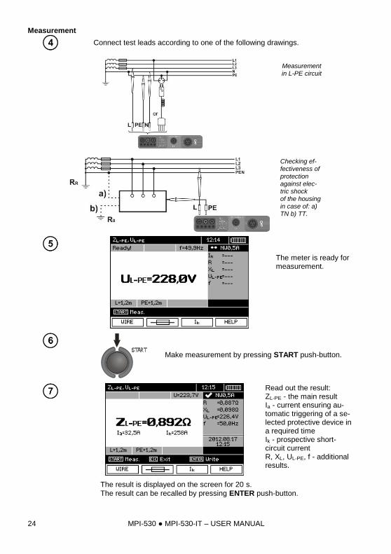
Connect test leads according to one of the following drawings.
Measurement in L-PE circuit
Checking ef-fectiveness of protection against elec-tric shock of the housing in case of: a) TN b) TT.
The meter is ready for measurement.
Make measurement by pressing START push-button.
Read out the result: ZL-PE - the main result Ia - current ensuring au-tomatic triggering of a se-lected protective device in a required time Ik - prospective short-circuit current R, XL, UL-PE, f - additional results.
The result is displayed on the screen for 20 s.
The result can be recalled by pressing ENTER push-button.
MPI-530 MPI-530-IT – USER MANUAL 25
Note:
- Double lead measurement is possible when a test lead other that the lead with a mains socket is se-lected. - Remaining issues connected with the measurements as well as the messages displayed are the same as those described for measurements in L-N circuit or L-L circuit.
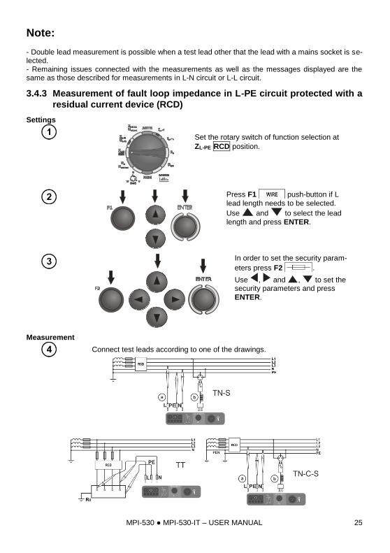
3.4.3 Measurement of fault loop impedance in L-PE circuit protected with a
residual current device (RCD)
Settings
Set the rotary switch of function selection at
ZL-PE RCD position.
Press F1 push-button if L
lead length needs to be selected.
Use and to select the lead
length and press ENTER.
In order to set the security param-
eters press F2 .
Use , and , to set the security parameters and press
ENTER.
Measurement
Connect test leads according to one of the drawings.
MPI-530 MPI-530-IT – USER MANUAL 26
Note:
- Maximum measurement time is about 32 seconds. The measurement can be interrupted by press-
ing ESC push-button. - In the electrical installations with 30 mA RCD's, the sum of leakage currents of the installation and the test current may trigger the RCD. If this happens, try to reduce the leakage current in the tested mains (for example by disconnecting loads). - Remaining issues connected with the measurements as well as the messages displayed are the same as those described for measurements L-PE circuit. - The function works for residual current devices of nominal current ≥ 30 mA.
Additional information displayed by the meter
Voltage absence
(e.g. N <-> PE)
Voltage absence during the measurement. The N and PE wires of the installation may be connected to the mains socket in reverse.
3.4.4 Prospective short-circuit current
The meter always measures impedance ZS. The short-circuit current is calculated according to the following formula:
S
kZ
UI
where: ZS - measured impedance, U - voltage that depends on settings of Ik button, according to the following Table:
The selection in MENU
Ik(Un) U = Un
Ik(U0) U = U0 for U0 < Un
U = Un for U0 ≥ Un
where: Un - nominal voltage of the network, U0 - the voltage during the measurement.
On the basis of Un rated voltage selected (section 2.2.1), the meter automatically recognizes the measurement at phase-to-neutral or phase-to-phase voltage and takes it into account in the calcula-tions. If the voltage of the network being tested is outside the tolerance range, the meter will not be able to determine a proper rated voltage for the short-circuit current calculation. In such a case, horizontal dashes will be displayed instead of short-circuit current value. The following diagram shows voltage ranges for which short-circuit current value is calculated.
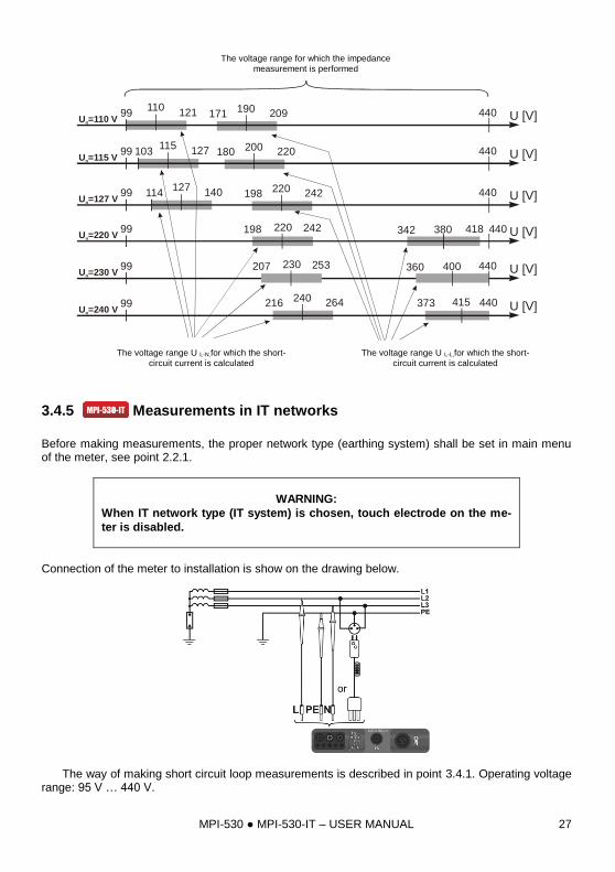
MPI-530 MPI-530-IT – USER MANUAL 27
230 400 440 U [V]
Zakresy napięć U , dla których
liczony jest prąd zwarciowyL-N
Zakres napięcia, dla którego wykonywany jest pomiar impedancji
207 253 360
115127 180 200 220
220 380 418198 242 342
373 415 440216 240 264
103 440 U [V]
440 U [V]
U [V]
U =115 Vn
U =220 Vn
U =230 Vn
U =240 Vn
Zakresy napięć U , dla których
liczony jest prąd zwarciowyL-L
110121 171 190 20999 440 U [V]U =110 Vn
127140 198 220 242114 440 U [V]U =127 Vn
99
99
99
99
99
3.4.5 Measurements in IT networks
Before making measurements, the proper network type (earthing system) shall be set in main menu of the meter, see point 2.2.1.
WARNING:
When IT network type (IT system) is chosen, touch electrode on the me-
ter is disabled.
Connection of the meter to installation is show on the drawing below.
The way of making short circuit loop measurements is described in point 3.4.1. Operating voltage range: 95 V … 440 V.
The voltage range for which the impedance
measurement is performed
The voltage range U L-N,for which the short-
circuit current is calculated
The voltage range U L-L,for which the short-
circuit current is calculated
MPI-530 MPI-530-IT – USER MANUAL 28
3.5 Measurement of resistance to earth
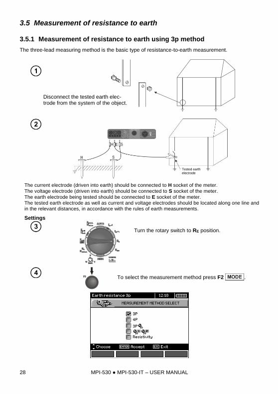
3.5.1 Measurement of resistance to earth using 3p method
The three-lead measuring method is the basic type of resistance-to-earth measurement.
Disconnect the tested earth elec-trode from the system of the object.
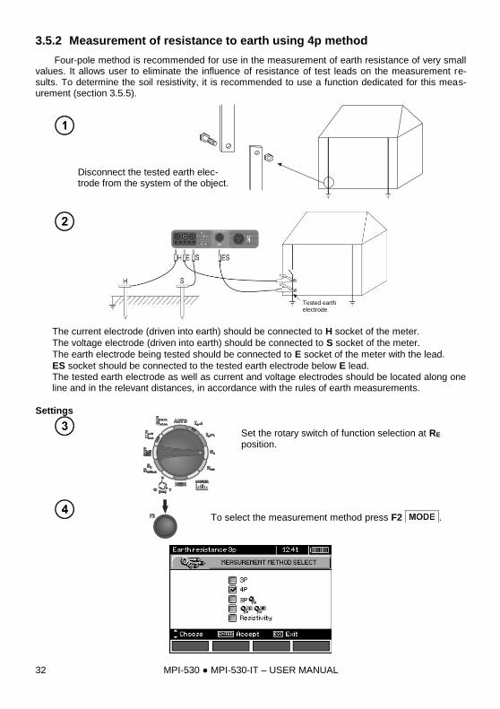
The current electrode (driven into earth) should be connected to H socket of the meter.
The voltage electrode (driven into earth) should be connected to S socket of the meter.
The earth electrode being tested should be connected to E socket of the meter.
The tested earth electrode as well as current and voltage electrodes should be located along one line and in the relevant distances, in accordance with the rules of earth measurements.
Settings
Turn the rotary switch to RE position.
To select the measurement method press F2 .
Tested earth electrode
MPI-530 MPI-530-IT – USER MANUAL 29
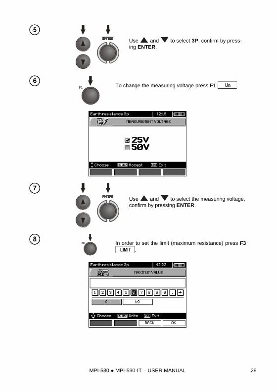
Use and to select 3P, confirm by press-
ing ENTER.
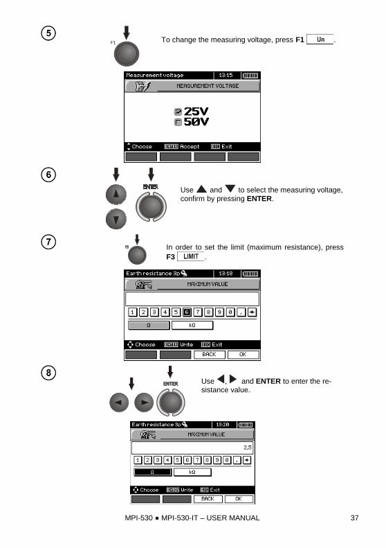
To change the measuring voltage press F1 .
Use and to select the measuring voltage,
confirm by pressing ENTER.
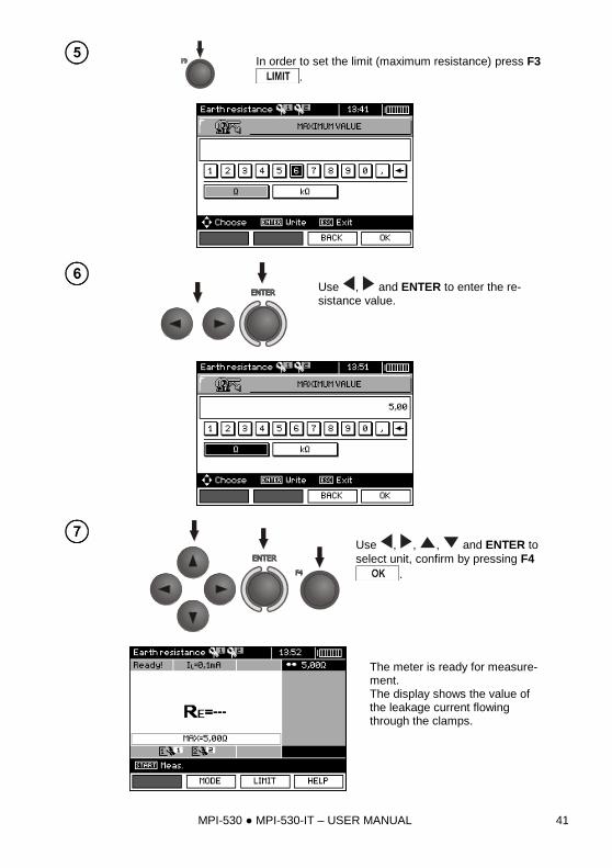
In order to set the limit (maximum resistance) press F3
.
MPI-530 MPI-530-IT – USER MANUAL 30
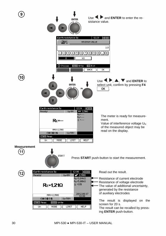
Use , and ENTER to enter the re-sistance value.
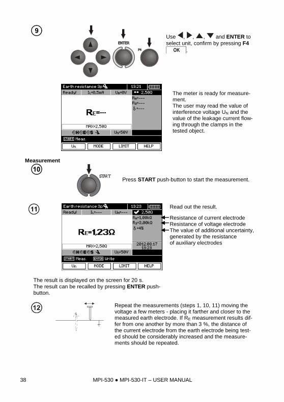
Use , , , and ENTER to
select unit, confirm by pressing F4
.
The meter is ready for measure-ment. Value of interference voltage UN of the measured object may be read on the display.
Measurement
Press START push-button to start the measurement.
Read out the result.
Resistance of current electrode Resistance of voltage electrode The value of additional uncertainty, generated by the resistance of auxiliary electrodes The result is displayed on the screen for 20 s. The result can be recalled by press-
ing ENTER push-button.
MPI-530 MPI-530-IT – USER MANUAL 31
S
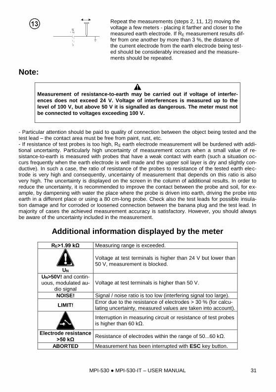
Repeat the measurements (steps 2, 11, 12) moving the voltage a few meters - placing it farther and closer to the measured earth electrode. If RE measurement results dif-fer from one another by more than 3 %, the distance of the current electrode from the earth electrode being test-ed should be considerably increased and the measure-ments should be repeated.
Note:
Measurement of resistance-to-earth may be carried out if voltage of interfer-
ences does not exceed 24 V. Voltage of interferences is measured up to the
level of 100 V, but above 50 V it is signalled as dangerous. The meter must not
be connected to voltages exceeding 100 V.
- Particular attention should be paid to quality of connection between the object being tested and the test lead – the contact area must be free from paint, rust, etc. - If resistance of test probes is too high, RE earth electrode measurement will be burdened with addi-tional uncertainty. Particularly high uncertainty of measurement occurs when a small value of re-sistance-to-earth is measured with probes that have a weak contact with earth (such a situation oc-curs frequently when the earth electrode is well made and the upper soil layer is dry and slightly con-ductive). In such a case, the ratio of resistance of the probes to resistance of the tested earth elec-trode is very high and consequently, uncertainty of measurement that depends on this ratio is also very high. The uncertainty is displayed on the screen in the column of additional results. In order to reduce the uncertainty, it is recommended to improve the contact between the probe and soil, for ex-ample, by dampening with water the place where the probe is driven into earth, driving the probe into earth in a different place or using a 80 cm-long probe. Check also the test leads for possible insula-tion damage and for corroded or loosened connection between the banana plug and the test lead. In majority of cases the achieved measurement accuracy is satisfactory. However, you should always be aware of the uncertainty included in the measurement.
Additional information displayed by the meter
RE>1.99 kΩ Measuring range is exceeded.
UN
Voltage at test terminals is higher than 24 V but lower than 50 V, measurement is blocked.
UN>50V! and contin-uous, modulated au-
dio signal
Voltage at test terminals is higher than 50 V.
NOISE! Signal / noise ratio is too low (interfering signal too large).
LIMIT! Error due to the resistance of electrodes > 30 % (for calcu-lating uncertainty, measured values are taken into account).
Interruption in measuring circuit or resistance of test probes is higher than 60 kΩ.
Electrode resistance
>50 kΩ Resistance of electrodes within the range of 50...60 kΩ.
ABORTED Measurement has been interrupted with ESC key button.
MPI-530 MPI-530-IT – USER MANUAL 32
3.5.2 Measurement of resistance to earth using 4p method
Four-pole method is recommended for use in the measurement of earth resistance of very small values. It allows user to eliminate the influence of resistance of test leads on the measurement re-sults. To determine the soil resistivity, it is recommended to use a function dedicated for this meas-urement (section 3.5.5).
Disconnect the tested earth elec-trode from the system of the object.
The current electrode (driven into earth) should be connected to H socket of the meter.
The voltage electrode (driven into earth) should be connected to S socket of the meter.
The earth electrode being tested should be connected to E socket of the meter with the lead.
ES socket should be connected to the tested earth electrode below E lead. The tested earth electrode as well as current and voltage electrodes should be located along one line and in the relevant distances, in accordance with the rules of earth measurements.
Settings
Set the rotary switch of function selection at RE position.
To select the measurement method press F2 .
Tested earth electrode
MPI-530 MPI-530-IT – USER MANUAL 33
Use and to select 4P, confirm by press-
ing ENTER.
To change the measuring voltage, press F1 .
Use and to select the measuring voltage,
confirm by pressing ENTER.
In order to set the limit (maximum resistance), press F3
.
MPI-530 MPI-530-IT – USER MANUAL 34
Use , and ENTER to enter the re-sistance value.
Use , , , and ENTER to
select unit. confirm by pressing F4
.
The meter is ready for measure-ment. Value of interference voltage UN of the measured object may be read on the display.
Measurement
Press START push-button to start the measurement.
Read out the result.
Resistance of current electrode Resistance of voltage electrode The value of additional uncertainty, generated by the resistance of auxiliary electrodes The result is displayed on the screen for 20 s. The result can be recalled by press-
ing ENTER push-button.
S
Repeat the measurements (steps 2, 11, 12) moving the voltage a few meters - placing it farther and closer to the measured earth electrode. If RE measurement results dif-fer from one another by more than 3 %, the distance of the current electrode from the earth electrode being test-ed should be considerably increased and the measure-ments should be repeated.
MPI-530 MPI-530-IT – USER MANUAL 35
Note:
Measurement of resistance-to-earth may be carried out if voltage of interfer-
ences does not exceed 24 V. Voltage of interferences is measured up to the
level of 100 V, but above 50 V it is signalled as dangerous. The meter must not
be connected to voltages exceeding 100 V.
- Particular attention should be paid to quality of connection between the object being tested and the test lead – the contact area must be free from paint, rust, etc. - If resistance of test probes is too high, RE earth electrode measurement will be burdened with addi-tional uncertainty. Particularly high uncertainty of measurement occurs when a small value of re-sistance-to-earth is measured with probes that have a weak contact with earth (such a situation oc-curs frequently when the earth electrode is well made and the upper soil layer is dry and slightly con-ductive). In such a case, the ratio of resistance of the probes to resistance of the tested earth elec-trode is very high and consequently, uncertainty of measurement that depends on this ratio is also very high. Then, you can make a calculations according to the formulas given in sec. 10.2 to estimate the influence of measurement conditions or you can use the graph also included in the appendix. You can improve the contact between the probe and soil, for example, by dampening with water the place where the probe is driven into earth, driving the probe into earth in a different place or using a 80 cm-long probe. Check also the test leads for possible insulation damage and for corroded or loosened connection between the banana plug and the test lead. In majority of cases the achieved measure-ment accuracy is satisfactory. However, you should always be aware of the uncertainty included in the measurement.
Additional information displayed by the meter
RE>1,99 kΩ Measuring range is exceeded.
UN>50V! and con-tinuous, modulated
audio signal
Voltage at test terminals is higher than 50 V, measure-ment is blocked.
UN
Voltage at test terminals is higher than 24 V but lower than 50 V, measurement is blocked.
LIMIT! The uncertainty due to the resistance of electrodes > 30 %. (For calculating uncertainty, measured values are tak-en into account.)
NOISE! The interfering signal (noise signal) is too high - the measurement result may be affected by additional uncer-tainty.
MPI-530 MPI-530-IT – USER MANUAL 36
3.5.3 Measurement of resistance to earth using 3p + clamps method
The current electrode (driven into earth) should be connected to H socket of the meter.
The voltage electrode (driven into earth) should be connected to S socket of the meter.
The earth electrode being tested should be connected to E socket of the meter with the lead. The tested earth electrode as well as current and voltage electrodes should be located along one line and in the relevant distances, in accordance with the rules of earth measurements.
Clamps should be attached to the tested earth electrode below the connection point of E lead.
Settings
Set the rotary switch of function selection at
RE position.
To select the measurement method press F2 .
Use and to select 3P , confirm by
pressing ENTER.
Tested earth electrode
MPI-530 MPI-530-IT – USER MANUAL 37
To change the measuring voltage, press F1 .
Use and to select the measuring voltage,
confirm by pressing ENTER.
In order to set the limit (maximum resistance), press
F3 .
Use , and ENTER to enter the re-sistance value.
MPI-530 MPI-530-IT – USER MANUAL 38
Use , , , and ENTER to
select unit, confirm by pressing F4
.
The meter is ready for measure-ment. The user may read the value of interference voltage UN and the value of the leakage current flow-ing through the clamps in the tested object.
Measurement
Press START push-button to start the measurement.
Read out the result.
Resistance of current electrode Resistance of voltage electrode The value of additional uncertainty, generated by the resistance of auxiliary electrodes
The result is displayed on the screen for 20 s.
The result can be recalled by pressing ENTER push-button.
S
Repeat the measurements (steps 1, 10, 11) moving the voltage a few meters - placing it farther and closer to the measured earth electrode. If RE measurement results dif-fer from one another by more than 3 %, the distance of the current electrode from the earth electrode being test-ed should be considerably increased and the measure-ments should be repeated.
MPI-530 MPI-530-IT – USER MANUAL 39
Note:
Measurement of resistance-to-earth may be carried out if voltage of interfer-
ences does not exceed 24 V. Voltage of interferences is measured up to the
level of 100 V, but above 50 V it is signalled as dangerous. The meter must not
be connected to voltages exceeding 100 V.
- Use C-3 clamps for the measurement. Clamps purchased with the meter must be calibrated before their first use. They may be periodically calibrated in order to prevent their ageing influence the accu-
racy of the measurements. Option for the calibration of clamps is included in the MENU. - Maximum interference current: 1 A. - Particular attention should be paid to quality of connection between the object being tested and the test lead – the contact area must be free from paint, rust, etc. - If resistance of test probes is too high, RE earth electrode measurement will be burdened with addi-tional uncertainty. Particularly high uncertainty of measurement occurs when a small value of re-sistance-to-earth is measured with probes that have a weak contact with earth (such a situation oc-curs frequently when the earth electrode is well made and the upper soil layer is dry and slightly con-ductive). In such a case, the ratio of resistance of the probes to resistance of the tested earth elec-trode is very high and consequently, uncertainty of measurement that depends on this ratio is also very high. Then, you can make a calculations according to the formulas given in sec. 10.2 to estimate the influence of measurement conditions or you can use the graph also included in the appendix. You can improve the contact between the probe and soil, for example, by dampening with water the place where the probe is driven into earth, driving the probe into earth in a different place or using a 80 cm-long probe. Check also the test leads for possible insulation damage and for corroded or loosened connection between the banana plug and the test lead. In majority of cases the achieved measure-ment accuracy is satisfactory. However, you should always be aware of the uncertainty included in the measurement. - Factory calibration does not include the resistance of the test leads. The result displayed by the me-ter is a sum of the resistance of the measured object and the resistance of leads.
Additional information displayed by the meter
RE>1.99 kΩ Measuring range is exceeded.
UN>50V! and con-tinuous, modulated
audio signal
Voltage at test terminals is higher than 50 V, measure-ment is blocked.
UN
Voltage at test terminals is higher than 24 V but lower than 50 V, measurement is blocked.
NOISE! The interfering signal (noise signal) is too high - the measurement result may be affected by additional uncer-tainty.
LIMIT! The uncertainty due to the resistance of electrodes > 30 %. (For calculating uncertainty, measured values are tak-en into account.)
IL>max The interference current is too high, the measurement er-ror may be larger than the basic error.
MPI-530 MPI-530-IT – USER MANUAL 40
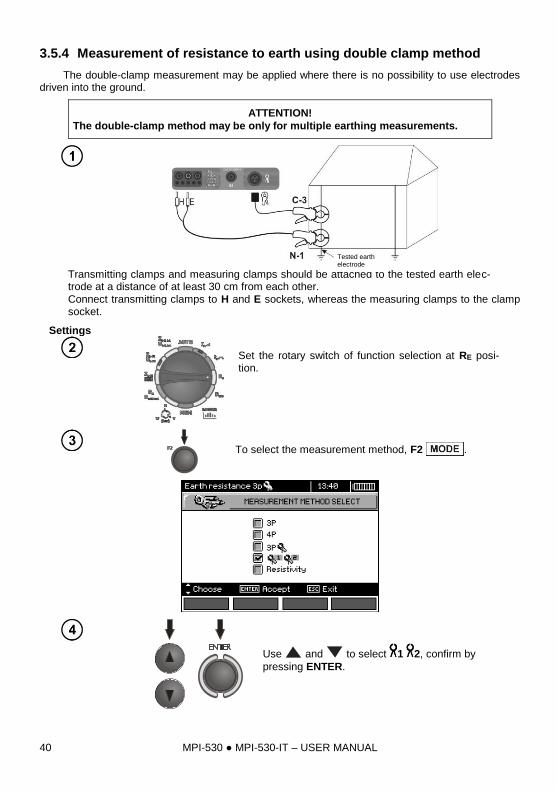
3.5.4 Measurement of resistance to earth using double clamp method
The double-clamp measurement may be applied where there is no possibility to use electrodes driven into the ground.
ATTENTION!
The double-clamp method may be only for multiple earthing measurements.
Transmitting clamps and measuring clamps should be attached to the tested earth elec-trode at a distance of at least 30 cm from each other.
Connect transmitting clamps to H and E sockets, whereas the measuring clamps to the clamp socket.
Settings
Set the rotary switch of function selection at RE posi-tion.
To select the measurement method, F2 .
Use and to select 1 2, confirm by
pressing ENTER.
Tested earth electrode
MPI-530 MPI-530-IT – USER MANUAL 41
In order to set the limit (maximum resistance) press F3
.
Use , and ENTER to enter the re-sistance value.
Use , , , and ENTER to
select unit, confirm by pressing F4
.
The meter is ready for measure-ment. The display shows the value of the leakage current flowing through the clamps.
MPI-530 MPI-530-IT – USER MANUAL 42
Measurement
Press STARTpush-button to start the measurement.
Read out the result. The result is displayed on the screen for 20 s. The result can be recalled by press-
ing ENTER push-button.
Note:
Measurements may be performed in the presence of interference current of a
value not exceeding 3 A rms and frequency in accordance with the value set in
MENU.
- Use N-1 clamps as signal transmitting clamps and C-3 clamps as receiving clamps. C-3 clamps purchased with the meter must be calibrated before their first use. They may be periodically calibrat-ed in order to prevent their ageing influence the accuracy of the measurements. Option for the cali-
bration of clamps is included in the MENU.
- If the current on measuring clamps is too low, the meter displays the following message: "Meas-
ured current is too low, measurement impossible!". - Maximum interference current: 1 A.
Additional information displayed by the meter
RE>99.9Ω Measuring range is exceeded.
UN>50V! and con-tinuous, modulated
audio signal
Voltage at test terminals is higher than 50 V, measure-ment is blocked.
UN
Voltage at test terminals is higher than 24 V but lower than 50 V, measurement is blocked.
NOISE! The interfering signal (noise signal) is too high - the measurement result may be affected by additional uncer-tainty.
MPI-530 MPI-530-IT – USER MANUAL 43
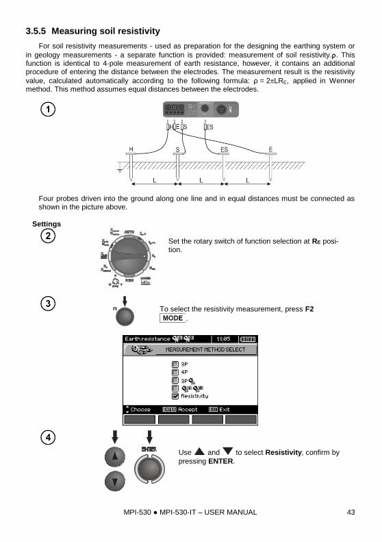
3.5.5 Measuring soil resistivity
For soil resistivity measurements - used as preparation for the designing the earthing system or
in geology measurements - a separate function is provided: measurement of soil resistivity.. This function is identical to 4-pole measurement of earth resistance, however, it contains an additional procedure of entering the distance between the electrodes. The measurement result is the resistivity
value, calculated automatically according to the following formula: ρ = 2LRE, applied in Wenner method. This method assumes equal distances between the electrodes.
Four probes driven into the ground along one line and in equal distances must be connected as shown in the picture above.
Settings
Set the rotary switch of function selection at RE posi-tion.
To select the resistivity measurement, press F2
.
Use and to select Resistivity, confirm by
pressing ENTER.
MPI-530 MPI-530-IT – USER MANUAL 44
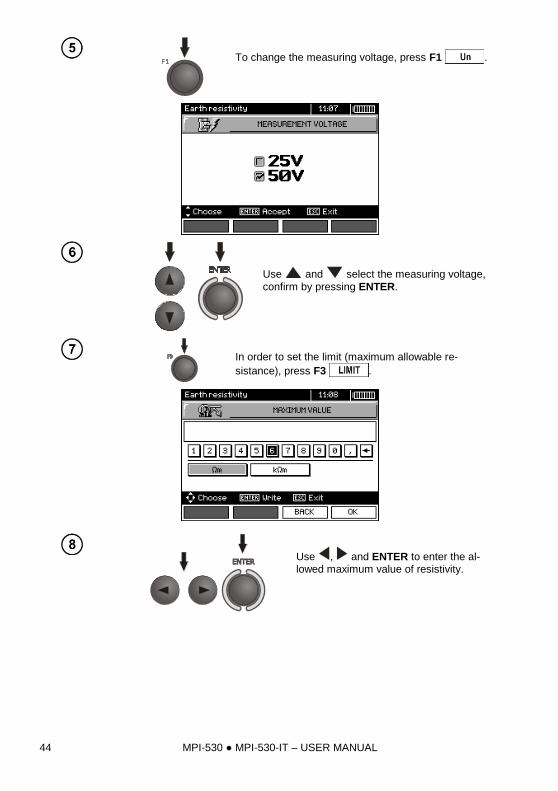
To change the measuring voltage, press F1 .
Use and select the measuring voltage,
confirm by pressing ENTER.
In order to set the limit (maximum allowable re-
sistance), press F3 .
Use , and ENTER to enter the al-lowed maximum value of resistivity.
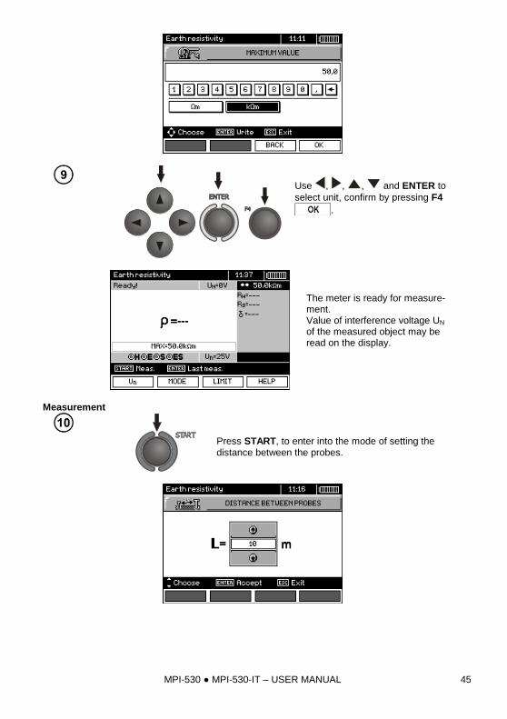
MPI-530 MPI-530-IT – USER MANUAL 45
Use , , , and ENTER to
select unit, confirm by pressing F4
.
The meter is ready for measure-ment. Value of interference voltage UN of the measured object may be read on the display.
Measurement
Press START, to enter into the mode of setting the distance between the probes.
MPI-530 MPI-530-IT – USER MANUAL 46
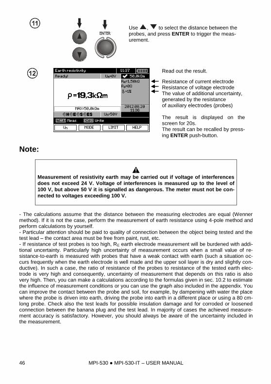
Use , to select the distance between the
probes, and press ENTER to trigger the meas-urement.
Read out the result.
Resistance of current electrode Resistance of voltage electrode The value of additional uncertainty, generated by the resistance of auxiliary electrodes (probes) The result is displayed on the screen for 20s. The result can be recalled by press-
ing ENTER push-button.
Note:
Measurement of resistivity earth may be carried out if voltage of interferences
does not exceed 24 V. Voltage of interferences is measured up to the level of
100 V, but above 50 V it is signalled as dangerous. The meter must not be con-
nected to voltages exceeding 100 V.
- The calculations assume that the distance between the measuring electrodes are equal (Wenner method). If it is not the case, perform the measurement of earth resistance using 4-pole method and perform calculations by yourself. - Particular attention should be paid to quality of connection between the object being tested and the test lead – the contact area must be free from paint, rust, etc. - If resistance of test probes is too high, RE earth electrode measurement will be burdened with addi-tional uncertainty. Particularly high uncertainty of measurement occurs when a small value of re-sistance-to-earth is measured with probes that have a weak contact with earth (such a situation oc-curs frequently when the earth electrode is well made and the upper soil layer is dry and slightly con-ductive). In such a case, the ratio of resistance of the probes to resistance of the tested earth elec-trode is very high and consequently, uncertainty of measurement that depends on this ratio is also very high. Then, you can make a calculations according to the formulas given in sec. 10.2 to estimate the influence of measurement conditions or you can use the graph also included in the appendix. You can improve the contact between the probe and soil, for example, by dampening with water the place where the probe is driven into earth, driving the probe into earth in a different place or using a 80 cm-long probe. Check also the test leads for possible insulation damage and for corroded or loosened connection between the banana plug and the test lead. In majority of cases the achieved measure-ment accuracy is satisfactory. However, you should always be aware of the uncertainty included in the measurement.
MPI-530 MPI-530-IT – USER MANUAL 47
Additional information displayed by the meter
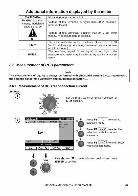
RE>99.9kΩm Measuring range is exceeded.
UN>50V! and con-tinuous, modulated
audio signal
Voltage at test terminals is higher than 50 V, measure-ment is blocked.
UN
Voltage at test terminals is higher than 24 V but lower than 50 V, measurement is blocked.
LIMIT! The uncertainty due to the resistance of electrodes > 30 %. (For calculating uncertainty, measured values are tak-en into account.)
NOISE! The interfering signal (noise signal) is too high - the measurement result may be affected by additional uncer-tainty.
3.6 Measurement of RCD parameters
Note:
The measurement of UB, RE is always performed with sinusoidal current 0,4In, regardless of
the settings concerning waveform and multiplication factor In.
3.6.1 Measurement of RCD disconnection current
Settings
Set the rotary switch of function selection at
IA position.
Press F1 to enter In
selection mode.
Press F2 to enter the
selection mode for current waveform.
Press F3 to enter RCD type selection mode.
Use and to select desired position and press
ENTER to confirm.
MPI-530 MPI-530-IT – USER MANUAL 48
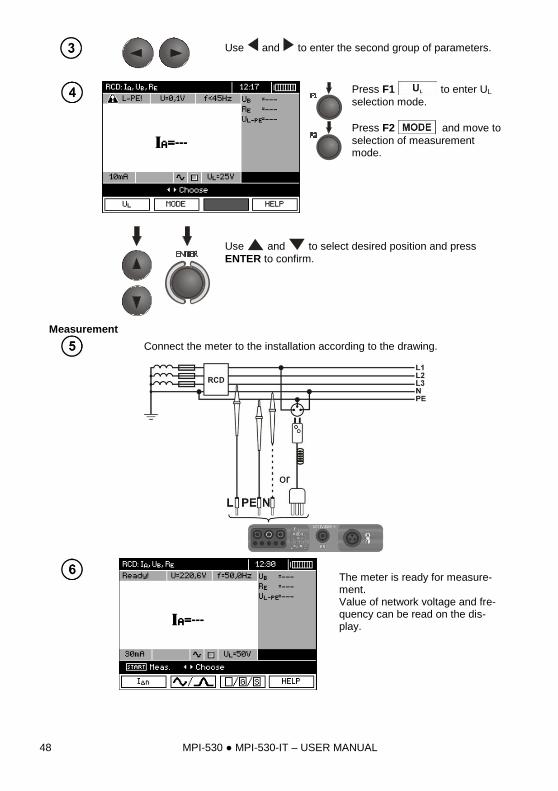
Use and to enter the second group of parameters.
Press F1 to enter UL
selection mode.
Press F2 and move to
selection of measurement mode.
Use and to select desired position and press
ENTER to confirm.
Measurement
Connect the meter to the installation according to the drawing.
The meter is ready for measure-ment. Value of network voltage and fre-quency can be read on the dis-play.
MPI-530 MPI-530-IT – USER MANUAL 49
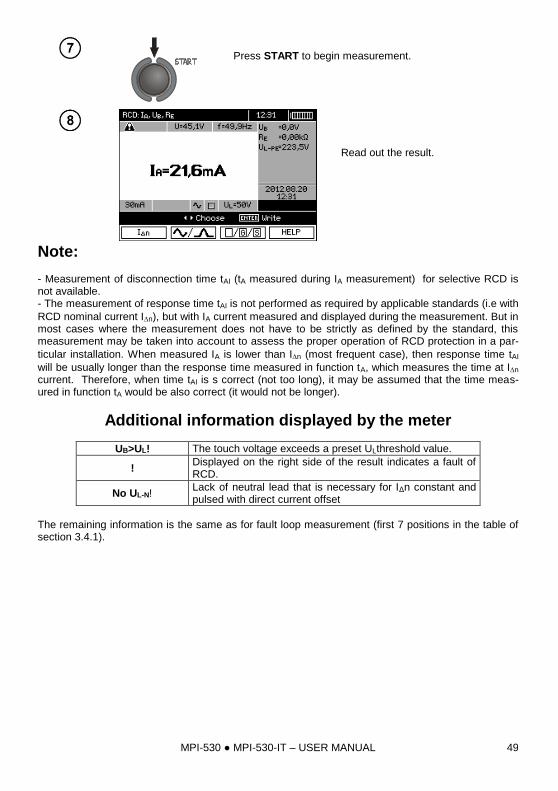
Press START to begin measurement.
Read out the result.
Note: - Measurement of disconnection time tAI (tA measured during IA measurement) for selective RCD is not available. - The measurement of response time tAI is not performed as required by applicable standards (i.e with
RCD nominal current In), but with IA current measured and displayed during the measurement. But in most cases where the measurement does not have to be strictly as defined by the standard, this measurement may be taken into account to assess the proper operation of RCD protection in a par-
ticular installation. When measured IA is lower than In (most frequent case), then response time tAI
will be usually longer than the response time measured in function tA, which measures the time at In current. Therefore, when time tAI is s correct (not too long), it may be assumed that the time meas-ured in function tA would be also correct (it would not be longer).
Additional information displayed by the meter
UB>UL! The touch voltage exceeds a preset ULthreshold value.
! Displayed on the right side of the result indicates a fault of RCD.
No UL-N! Lack of neutral lead that is necessary for IΔn constant and pulsed with direct current offset
The remaining information is the same as for fault loop measurement (first 7 positions in the table of section 3.4.1).
MPI-530 MPI-530-IT – USER MANUAL 50
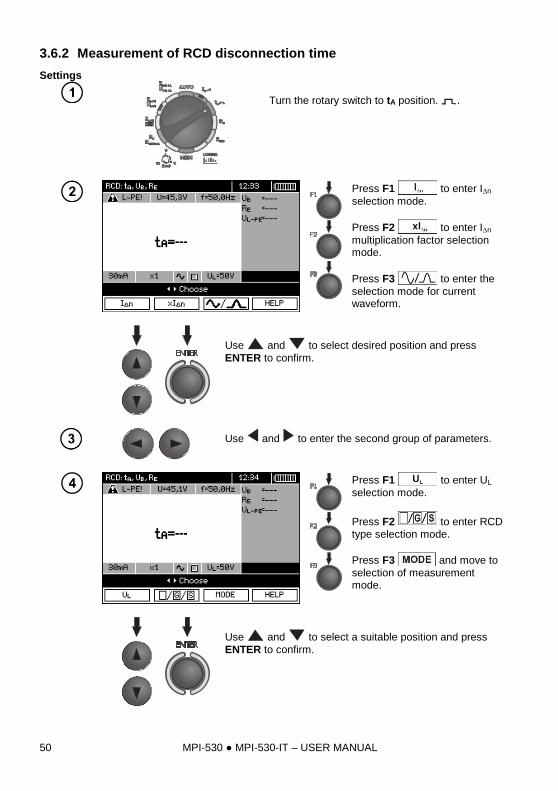
3.6.2 Measurement of RCD disconnection time
Settings
Turn the rotary switch to tA position. .
Press F1 to enter In
selection mode.
Press F2 to enter In
multiplication factor selection mode.
Press F3 to enter the
selection mode for current waveform.
Use and to select desired position and press
ENTER to confirm.
Use and to enter the second group of parameters.
Press F1 to enter UL
selection mode.
Press F2 to enter RCD type selection mode.
Press F3 and move to
selection of measurement mode.
Use and to select a suitable position and press
ENTER to confirm.
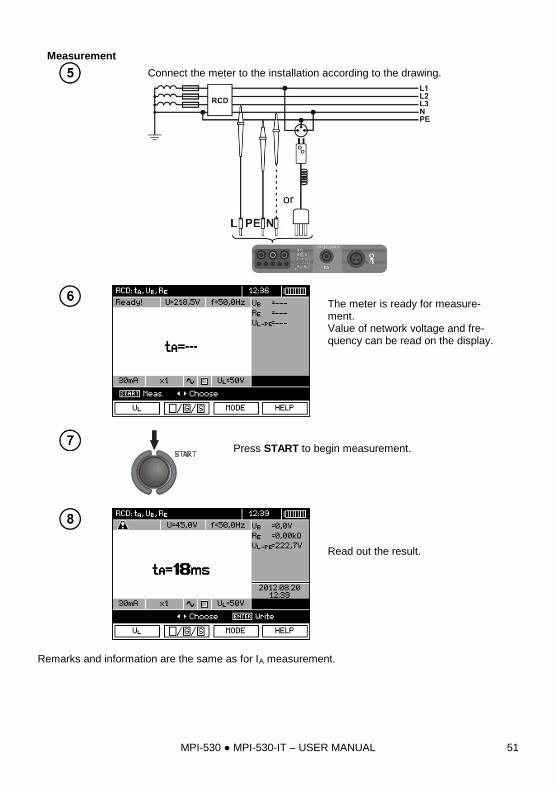
MPI-530 MPI-530-IT – USER MANUAL 51
Measurement
Connect the meter to the installation according to the drawing.
The meter is ready for measure-ment. Value of network voltage and fre-quency can be read on the display.
Press START to begin measurement.
Read out the result.
Remarks and information are the same as for IA measurement.
MPI-530 MPI-530-IT – USER MANUAL 52
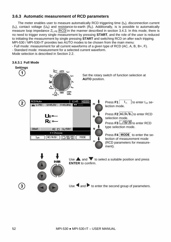
3.6.3 Automatic measurement of RCD parameters
The meter enables user to measure automatically RCD triggering time (tA), disconnection current (IA), contact voltage (UB) and resistance-to-earth (RE). Additionally, is is possible to automatically
measure loop impedance ZL-PE RCD in the manner described in section 3.4.3. In this mode, there is
no need to trigger every single measurement by pressing START, and the role of the user is reduced
to initiating the measurement by single pressing START and switching RCD on after each tripping. MPI-530 / MPI-530-IT provides two AUTO modes to be chosen from the main menu: - Full mode: measurement for all current waveforms of a given type of RCD (AC, A, B, B+, F). - Standard mode: measurement for a selected current waveform. Mode selection is described in Section 2.2.
3.6.3.1 Full Mode
Settings
Set the rotary switch of function selection at
AUTO position.
Press F1 to enter In se-
lection mode.
Press F2 to enter RCD
selection mode.
Press F3 to enter RCD type selection mode.
Press F4 to enter the se-
lection of measurement mode (RCD parameters for measure-ment).
Use and to select a suitable position and press
ENTER to confirm.
Use and to enter the second group of parameters.
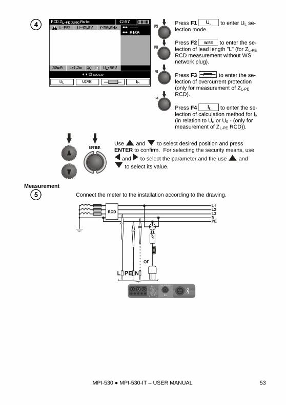
MPI-530 MPI-530-IT – USER MANUAL 53
Press F1 to enter UL se-
lection mode.
Press F2 to enter the se-
lection of lead length "L" (for ZL-PE RCD measurement without WS network plug).
Press F3 to enter the se-
lection of overcurrent protection (only for measurement of ZL-PE RCD).
Press F4 to enter the se-
lection of calculation method for Ik (in relation to Un or U0 - (only for measurement of ZL-PE RCD)).
Use and to select desired position and press
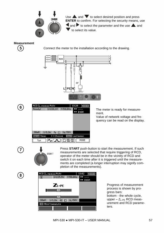
ENTER to confirm. For selecting the security means, use
and to select the parameter and the use and
to select its value.
Measurement
Connect the meter to the installation according to the drawing.
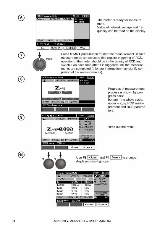
MPI-530 MPI-530-IT – USER MANUAL 54
The meter is ready for measure-ment. Value of network voltage and fre-quency can be read on the display.
Press START push-button to start the measurement. If such measurements are selected that require triggering of RCD, operator of the meter should be in the vicinity of RCD and switch it on each time after it is triggered until the measure-ments are completed (a longer interruption may signify com-pletion of the measurements).
Progress of measurement process is shown by pro-gress bars: bottom - the whole cycle, upper – ZL-PE RCD meas-urement and RCD parame-ters.
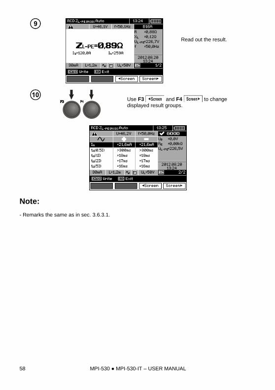
Read out the result.
Use F3 and F4 to change
displayed result groups.
MPI-530 MPI-530-IT – USER MANUAL 55
Note: - The number of measured parameters depends on the settings entered in the main menu. - UB and RE are always measured. - Automatic measurement is interrupted in the following cases:
the switch was tripped during the measurement of UB RE or tA at the half value of IΔn,
the switch did not trip during other component measurements,
the value of safe voltage UL has been exceeded,
voltage was disconnected during one of the component measurements,
values RE and mains voltage did not allow to generate the required current value for one of com-ponent measurements.
- The meter automatically skips the measurements impossible to perform, e.g. when the value of se-lected IΔn current and its multiplication factor exceed the testing range of the meter. - Criteria for assessing the correctness of component results:
0.5*IΔn ≤ IA ≤ 1*IΔn
0.35*IΔn ≤ IA i ≤ 2*IΔn for IΔn =10 mA
0.35*IΔn ≤ IA and ≤ 1.4*IΔn for remaining IΔn
0.5*IΔn ≤ IA ≤ 2*IΔn
tA at 0.5*IΔn → rcd, for all types of RCD
tA at 1*IΔn ≤ 300 ms for standard RCD's
tA at 2*IΔn ≤ 150 ms for standard RCD's
tA at 5*IΔn ≤ 40 ms for standard RCD's
130 ms ≤ tA at 1*IΔn ≤ 500 ms for selective RCD's
60 ms ≤ tA at 2*IΔn ≤ 200 ms for selective RCD's
50 ms ≤ tA at 5*IΔn ≤ 150 ms for selective RCD's
10 ms ≤ tA at 1*IΔn ≤ 300 ms for short-time delay RCD's
10 ms ≤ tA at 2*IΔn ≤ 150 ms for short-time delay RCD's
10 ms ≤ tA at 5*IΔn ≤ 40 ms for short-time delay RCD's
- Store the result in the memory (see sec. 4.2) or press ESC, and display only network voltage and frequency. - Remaining remarks and information are the same as for IA and ZL-PEmeasurement.
MPI-530 MPI-530-IT – USER MANUAL 56
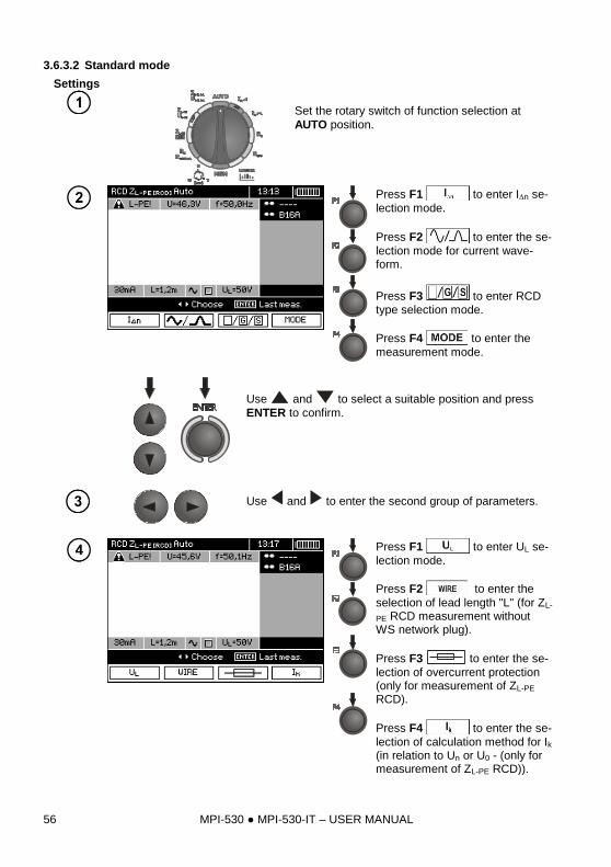
3.6.3.2 Standard mode
Settings
Set the rotary switch of function selection at
AUTO position.
Press F1 to enter In se-
lection mode.
Press F2 to enter the se-
lection mode for current wave-form.
Press F3 to enter RCD type selection mode.
Press F4 to enter the
measurement mode.
Use and to select a suitable position and press
ENTER to confirm.
Use and to enter the second group of parameters.
Press F1 to enter UL se-
lection mode.
Press F2 to enter the
selection of lead length "L" (for ZL-
PE RCD measurement without WS network plug).
Press F3 to enter the se-
lection of overcurrent protection (only for measurement of ZL-PE RCD).
Press F4 to enter the se-
lection of calculation method for Ik (in relation to Un or U0 - (only for measurement of ZL-PE RCD)).
MPI-530 MPI-530-IT – USER MANUAL 57
Use and to select desired position and press
ENTER to confirm. For selecting the security means, use
and to select the parameter and the use and
to select its value.
Measurement
Connect the meter to the installation according to the drawing.
The meter is ready for measure-ment. Value of network voltage and fre-quency can be read on the display.
Press START push-button to start the measurement. If such measurements are selected that require triggering of RCD, operator of the meter should be in the vicinity of RCD and switch it on each time after it is triggered until the measure-ments are completed (a longer interruption may signify com-pletion of the measurements).
Progress of measurement process is shown by pro-gress bars: bottom - the whole cycle, upper – ZL-PE RCD meas-urement and RCD parame-ters.
MPI-530 MPI-530-IT – USER MANUAL 58
Read out the result.
Use F3 and F4 to change
displayed result groups.
Note:
- Remarks the same as in sec. 3.6.3.1.
MPI-530 MPI-530-IT – USER MANUAL 59
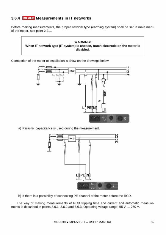
3.6.4 Measurements in IT networks
Before making measurements, the proper network type (earthing system) shall be set in main menu of the meter, see point 2.2.1.
WARNING:
When IT network type (IT system) is chosen, touch electrode on the meter is
disabled.
Connection of the meter to installation is show on the drawings below.
a) Parasitic capacitance is used during the measurement.
b) If there is a possibility of connecting PE channel of the meter before the RCD. The way of making measurements of RCD tripping time and current and automatic measure-ments is described in points 3.6.1, 3.6.2 and 3.6.3. Operating voltage range: 95 V … 270 V.
MPI-530 MPI-530-IT – USER MANUAL 60
3.7 Measurement of insulation resistance
WARNING:
The tested object must not be live.
3.7.1 Double-lead measurement
Settings
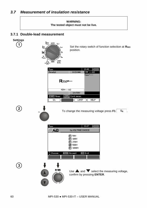
Set the rotary switch of function selection at RISO position.
To change the measuring voltage press F1 .
Use and select the measuring voltage,
confirm by pressing ENTER.
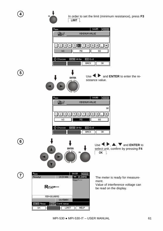
MPI-530 MPI-530-IT – USER MANUAL 61
In order to set the limit (minimum resistance), press F3
.
Use , and ENTER to enter the re-sistance value.
Use , , , and ENTER to
select unit, confirm by pressing F4
.
The meter is ready for measure-ment. Value of interference voltage can be read on the display.
MPI-530 MPI-530-IT – USER MANUAL 62
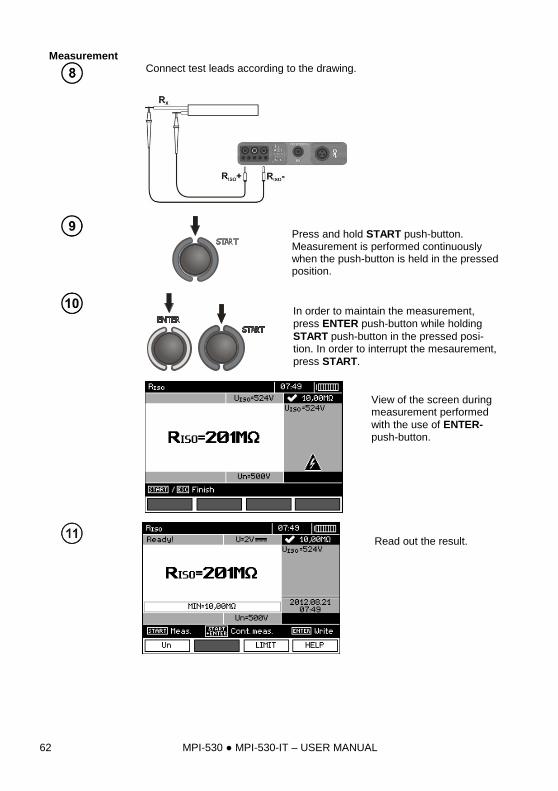
Measurement
Connect test leads according to the drawing.
Press and hold START push-button. Measurement is performed continuously when the push-button is held in the pressed position.
In order to maintain the measurement,
press ENTER push-button while holding
START push-button in the pressed posi-tion. In order to interrupt the mesaurement,
press START.
View of the screen during measurement performed
with the use of ENTER-push-button.
Read out the result.
MPI-530 MPI-530-IT – USER MANUAL 63
Note:
During measurements of insulation resistance, dangerous voltage up to 1 kV
occurs at the ends of test leads of MPI-530 / MPI-530-IT.
It is forbidden to disconnect test leads and to change the position of the func-
tion switch before completion of measurement. Failure to obey the above in-
struction will lead to high voltage electric shock and make it impossible to dis-
charge the tested object.
- The meter emits a continuous audio signal until test voltage reaches 90 % of the preset value (and also when 110 % of the preset value is exceeded). - After completion of measurement, the capacitance of the object tested is discharged by shorting
RISO+ and RISO- terminals with resistance of 100 k.
Additional information displayed by the meter
Test voltage is present on terminals of the meter.
NOISE! Interference voltage occurs on the tested object. Meas-urement is possible but may be burdened with additional uncertainty.
LIMIT I!
Current limit tripped. The symbol displayed during the measurement is accompanied by a continuous beep. If this symbol is displayed after the measurement, it means that the measurement result was obtained during operation with a current limiting device.
3.7.2 Measurements by means of leads with UNI-Schuko outlet plug (WS-03
and WS-04)
Settings
Set the rotary switch of function selection at
RISO position.
Connect WS-03 lead or WS-04 lead with UNI-Schuko outlet plug. The meter detects this fact auto-matically and changes the appear-ance of the screen.
MPI-530 MPI-530-IT – USER MANUAL 64
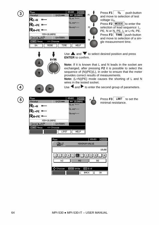
Press F1 push-button
and move to selection of test voltage UN.
Press F2 to enter the
selection of lead sequence: L, PE, N or N, PE, L or L+N, PE.
Press F3 push-button
and move to selection of a sin-gle measurement time.
Use and to select desired position and press
ENTER to confirm.
Note: If it is known that L and N leads in the socket are
exchanged, after pressing F2 it is possible to select the sequence of (N)(PE)(L), in order to ensure that the meter provides correct results of measurements.
Note: (L+N)(PE) mode causes the shorting of L and N wires in the tested socket.
Use and to enter the second group of parameters.
Press F3 to set the
minimal resistance.
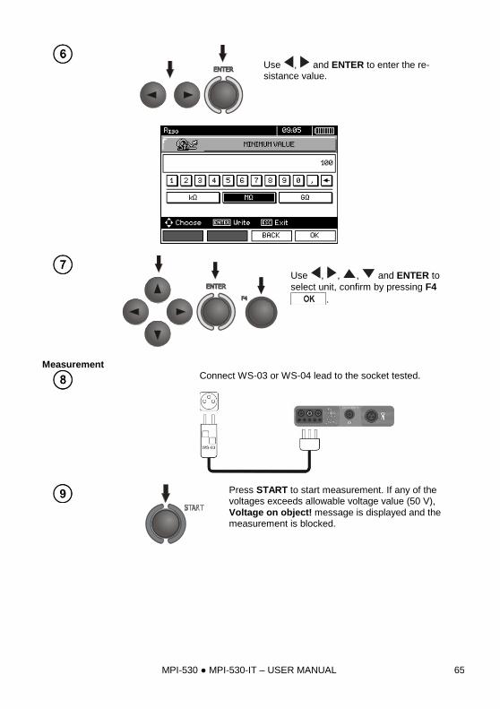
MPI-530 MPI-530-IT – USER MANUAL 65
Use , and ENTER to enter the re-sistance value.
Use , , , and ENTER to
select unit, confirm by pressing F4
.
Measurement
Connect WS-03 or WS-04 lead to the socket tested.
Press START to start measurement. If any of the voltages exceeds allowable voltage value (50 V),
Voltage on object! message is displayed and the measurement is blocked.
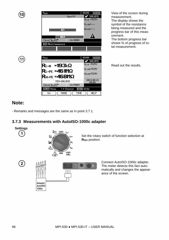
MPI-530 MPI-530-IT – USER MANUAL 66
View of the screen during measurement. The display shows the symbol of the resistance being measured and the progress bar of this meas-urement. The bottom progress bar shows % of progress of to-tal measurement.
Read out the results.
Note: - Remarks and messages are the same as in point 3.7.1.
3.7.3 Measurements with AutoISO-1000c adapter
Settings
Set the rotary switch of function selection at
RISO position.
Connect AutoISO-1000c adapter. The meter detects this fact auto-matically and changes the appear-ance of the screen.
MPI-530 MPI-530-IT – USER MANUAL 67
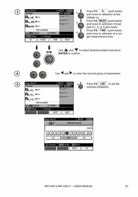
Press F1 push-button
and move to selection of test voltage UN.
Press F2 push-button
and move to selection of lead type (3-, 4- or 5-wire lead).
Press F3 push-button
and move to selection of a sin-gle measurement time.
Use and to select desired position and press
ENTER to confirm.
Use and to enter the second group of parameters.
Press F3 to set the
minimal resistance.
MPI-530 MPI-530-IT – USER MANUAL 68
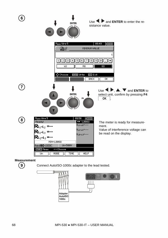
Use , and ENTER to enter the re-sistance value.
Use , , , and ENTER to
select unit, confirm by pressing F4
.
The meter is ready for measure-ment. Value of interference voltage can be read on the display.
Measurement
Connect AutoISO-1000c adapter to the lead tested.
MPI-530 MPI-530-IT – USER MANUAL 69
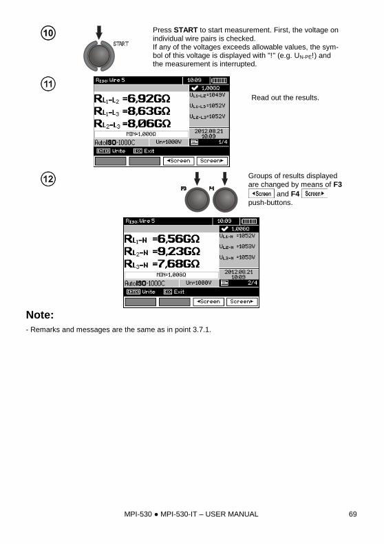
Press START to start measurement. First, the voltage on individual wire pairs is checked. If any of the voltages exceeds allowable values, the sym-bol of this voltage is displayed with "!" (e.g. UN-PE!) and the measurement is interrupted.
Read out the results.
Groups of results displayed
are changed by means of F3
and F4
push-buttons.
Note:
- Remarks and messages are the same as in point 3.7.1.
MPI-530 MPI-530-IT – USER MANUAL 70
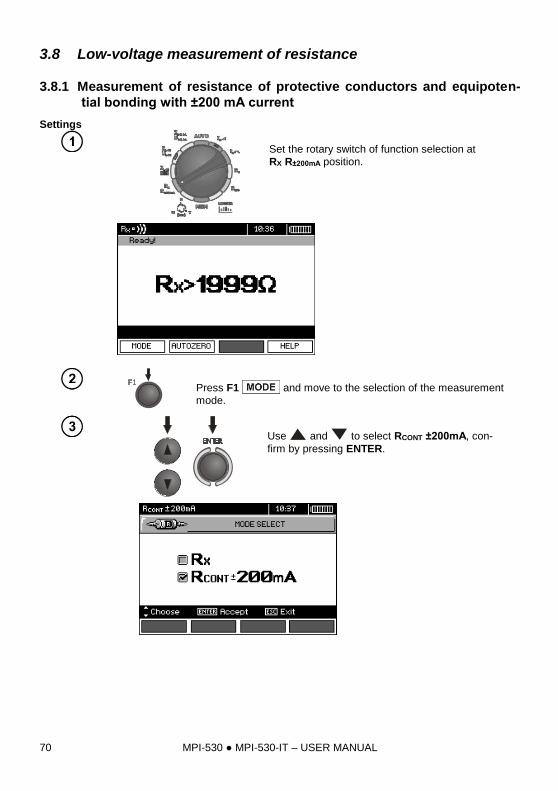
3.8 Low-voltage measurement of resistance
3.8.1 Measurement of resistance of protective conductors and equipoten-
tial bonding with ±200 mA current
Settings
Set the rotary switch of function selection at
RX R±200mA position.
Press F1 and move to the selection of the measurement
mode.
Use and to select RCONT ±200mA, con-
firm by pressing ENTER.
MPI-530 MPI-530-IT – USER MANUAL 71
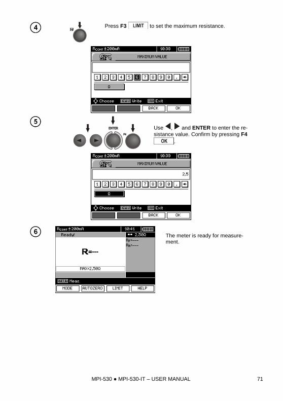
Press F3 to set the maximum resistance.
Use , and ENTER to enter the re-
sistance value. Confirm by pressing F4
.
The meter is ready for measure-ment.
MPI-530 MPI-530-IT – USER MANUAL 72
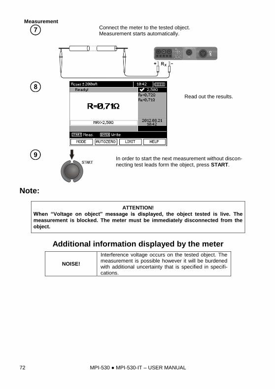
Measurement
Connect the meter to the tested object. Measurement starts automatically.
Read out the results.
In order to start the next measurement without discon-
necting test leads form the object, press START.
Note:
ATTENTION!
When “Voltage on object” message is displayed, the object tested is live. The
measurement is blocked. The meter must be immediately disconnected from the
object.
Additional information displayed by the meter
NOISE!
Interference voltage occurs on the tested object. The measurement is possible however it will be burdened with additional uncertainty that is specified in specifi-cations.
MPI-530 MPI-530-IT – USER MANUAL 73
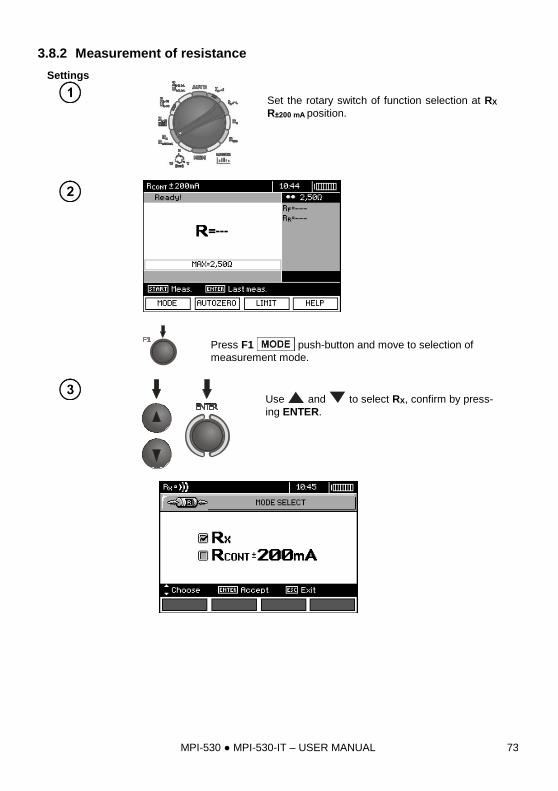
3.8.2 Measurement of resistance
Settings
Set the rotary switch of function selection at RX
R±200 mA position.
Press F1 push-button and move to selection of
measurement mode.
Use and to select RX, confirm by press-
ing ENTER.
MPI-530 MPI-530-IT – USER MANUAL 74
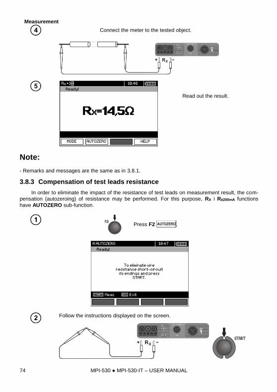
Measurement
Connect the meter to the tested object.
Read out the result.
Note: - Remarks and messages are the same as in 3.8.1.
3.8.3 Compensation of test leads resistance
In order to eliminate the impact of the resistance of test leads on measurement result, the com-
pensation (autozeroing) of resistance may be performed. For this purpose, RX i R±200mA functions
have AUTOZERO sub-function.
Press F2 .
Follow the instructions displayed on the screen.
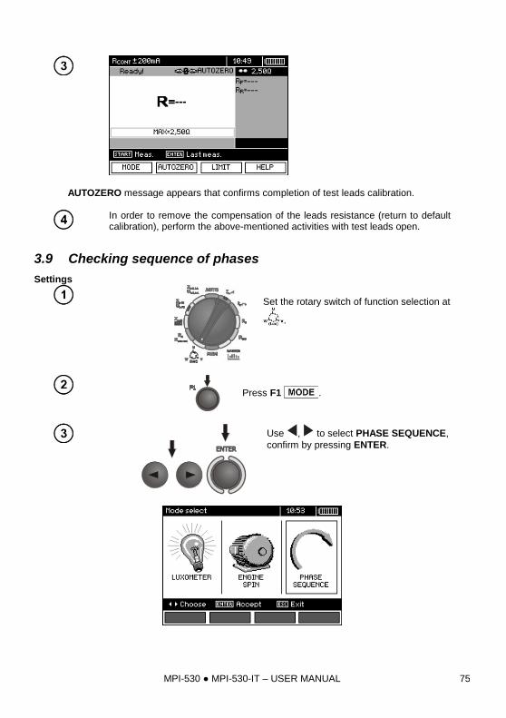
MPI-530 MPI-530-IT – USER MANUAL 75
AUTOZERO message appears that confirms completion of test leads calibration.
In order to remove the compensation of the leads resistance (return to default calibration), perform the above-mentioned activities with test leads open.
3.9 Checking sequence of phases
Settings
Set the rotary switch of function selection at
.
Press F1 .
Use , to select PHASE SEQUENCE,
confirm by pressing ENTER.
MPI-530 MPI-530-IT – USER MANUAL 76
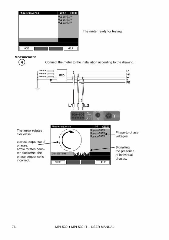
The meter ready for testing.
Measurement
Connect the meter to the installation according to the drawing.
The arrow rotates clockwise: correct sequence of phases, arrow rotates coun-ter-clockwise: the phase sequence is incorrect.
Phase-to-phase voltages. Signalling the presence of individual phases.
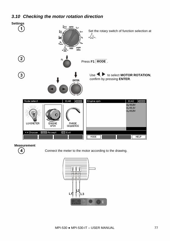
MPI-530 MPI-530-IT – USER MANUAL 77
3.10 Checking the motor rotation direction
Settings
Set the rotary switch of function selection at
.
Press F1 .
Use , to select MOTOR ROTATION,
confirm by pressing ENTER.
Measurement
Connect the meter to the motor according to the drawing.
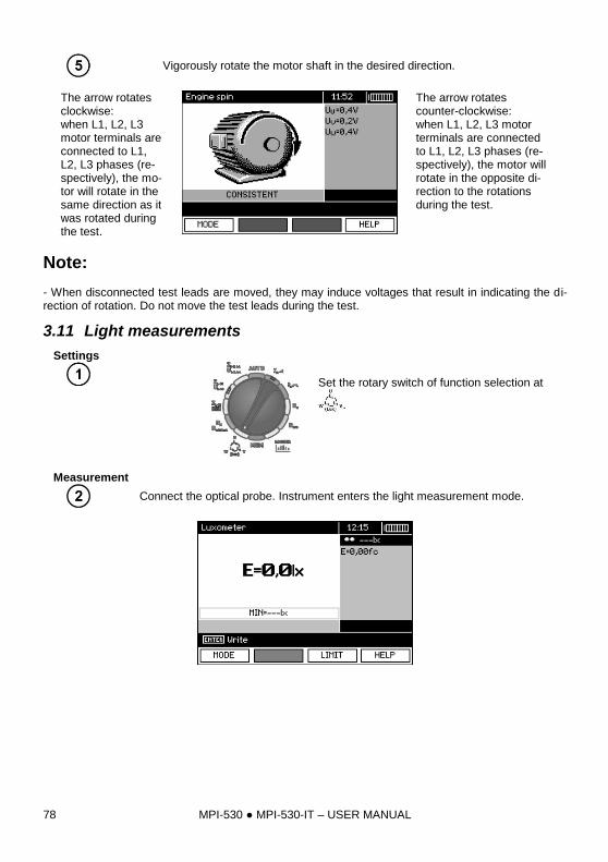
MPI-530 MPI-530-IT – USER MANUAL 78
Vigorously rotate the motor shaft in the desired direction.
The arrow rotates clockwise: when L1, L2, L3 motor terminals are connected to L1, L2, L3 phases (re-spectively), the mo-tor will rotate in the same direction as it was rotated during the test.
The arrow rotates counter-clockwise: when L1, L2, L3 motor terminals are connected to L1, L2, L3 phases (re-spectively), the motor will rotate in the opposite di-rection to the rotations during the test.
Note: - When disconnected test leads are moved, they may induce voltages that result in indicating the di-rection of rotation. Do not move the test leads during the test.
3.11 Light measurements
Settings
Set the rotary switch of function selection at
.
Measurement
Connect the optical probe. Instrument enters the light measurement mode.
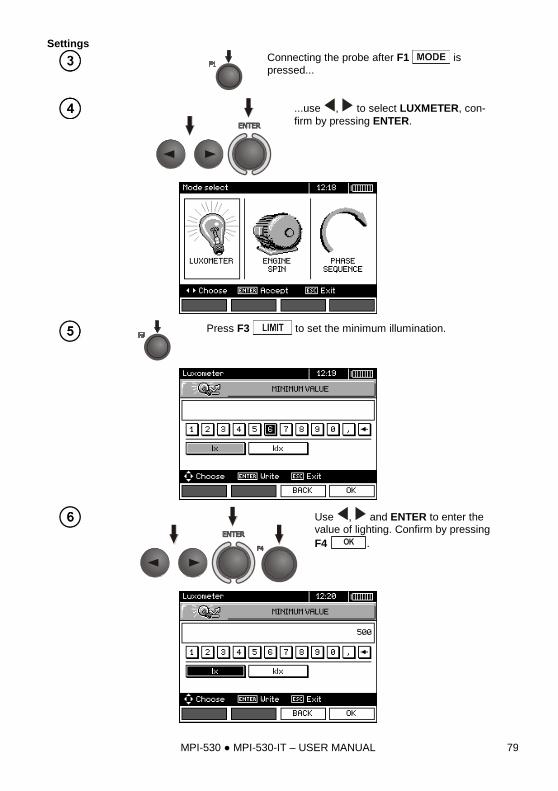
MPI-530 MPI-530-IT – USER MANUAL 79
Settings
Connecting the probe after F1 is
pressed...
...use , to select LUXMETER, con-
firm by pressing ENTER.
Press F3 to set the minimum illumination.
Use , and ENTER to enter the value of lighting. Confirm by pressing
F4 OK .
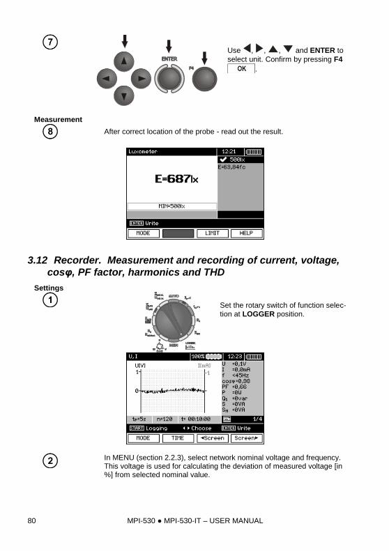
MPI-530 MPI-530-IT – USER MANUAL 80
Use , , , and ENTER to
select unit. Confirm by pressing F4
.
Measurement
After correct location of the probe - read out the result.
3.12 Recorder. Measurement and recording of current, voltage,
cosφ, PF factor, harmonics and THD
Settings
Set the rotary switch of function selec-
tion at LOGGER position.
In MENU (section 2.2.3), select network nominal voltage and frequency. This voltage is used for calculating the deviation of measured voltage [in %] from selected nominal value.
MPI-530 MPI-530-IT – USER MANUAL 81
Press F1 , to select the parameters to
be recorded.
Use , to select the parameter set for
recording, press ENTER to approve.
Press F2 , to set the sampling time and number of
samples.
Use , and ENTER to select the sampling period.
Use , to select the number of samples,
then use , to set the number of sam-ples - the recording time is calculated basing on the sampling time and the number of
samples. Press F4 to enter the
measurement screen.
MPI-530 MPI-530-IT – USER MANUAL 82
Use , to change the appearance of the setting bar. Press F3
to enter the selection of clamp type.
Use , to select the type of clamps,
press ENTER to approve.
Measurement
Connect the device according to the drawing (example of measurement on a motor).
MPI-530 MPI-530-IT – USER MANUAL 83
Groups of results displayed are changed by means
of F3 and F4 push-buttons.
When displaying harmonics, use , to select the number of the harmonic, with the value dis-played on the right side of the screen.
MPI-530 MPI-530-IT – USER MANUAL 84
Press START to start recording.
Note:
Note:
In order to avoid ambiguity in the calculating power values, attach clamps with their ar-
rows indicating the point of connecting L terminal of the meter to the tested object (Figure
b)).
- During recording only one screen is displayed - the one that was displayed at the start of recording. - In order to save energy, the meter displays data for 30 seconds from activating it, then it enters en-ergy saving mode (the screen is blanked, LED flashes with 1-sec intervals). Pressing any key acti-vates the device from the standby mode.
4 Memory of measurement results
4.1 Structure of the Memory
The memory for test results has a tree-like structure (see figure below). The user has the ability to record data for ten clients. Each client may create max. 999 objects, which may store up to three levels of sub-objects, 999 sub-objects for each level. Each subject, and sub-object may store up to 999 measurements.
The whole structure is limited by the size of memory. The memory allows for simultaneous re-cording of 10 full descriptions of customers, and a minimum of: measurement sets for 10000 measur-ing points and 10000 names of these points, 999 names for objects, 999 descriptions of sub-objects and remember the layout created for these objects. Additionally the memory has a space for the list of names (selection lists) extended up to 99 entries.
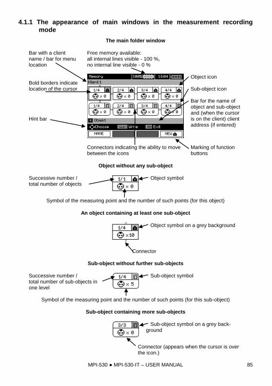
MPI-530 MPI-530-IT – USER MANUAL 85
4.1.1 The appearance of main windows in the measurement recording
mode
The main folder window
Bar with a client name / bar for menu location
Free memory available: all internal lines visible - 100 %, no internal line visible - 0 %
Bold borders indicate location of the cursor Hint bar
Object icon Sub-object icon Bar for the name of object and sub-object and (when the cursor is on the client) client address (if entered)
Connectors indicating the ability to move between the icons
Marking of function buttons
Object without any sub-object
Successive number / total number of objects
Object symbol
Symbol of the measuring point and the number of such points (for this object)
An object containing at least one sub-object
Object symbol on a grey background
Connector
Sub-object without further sub-objects
Successive number / total number of sub-objects in one level
Sub-object symbol
Symbol of the measuring point and the number of such points (for this sub-object)
Sub-object containing more sub-objects
Sub-object symbol on a grey back-ground
Connector (appears when the cursor is over the icon.)
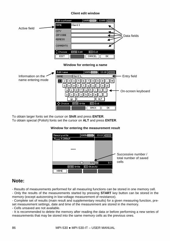
MPI-530 MPI-530-IT – USER MANUAL 86
Client edit window
Active field
Data fields
Window for entering a name
Information on the name entering mode
Entry field On-screen keyboard
To obtain larger fonts set the cursor on Shift and press ENTER.
To obtain special (Polish) fonts set the cursor on ALT and press ENTER.
Window for entering the measurement result
Successive number / total number of saved cells
Note: - Results of measurements performed for all measuring functions can be stored in one memory cell.
- Only the results of the measurements started by pressing START key button can be stored in the memory (except autozeroing in low-voltage measurement of resistance). - Complete set of results (main result and supplementary results) for a given measuring function, pre-set measurement settings, date and time of the measurement are stored in the memory. - Cells unsaved are not available. - It is recommended to delete the memory after reading the data or before performing a new series of measurements that may be stored into the same memory cells as the previous ones.
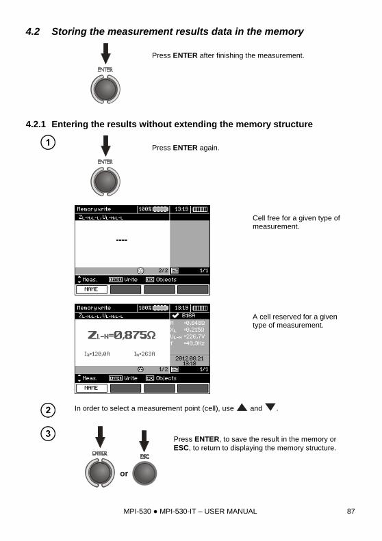
MPI-530 MPI-530-IT – USER MANUAL 87
4.2 Storing the measurement results data in the memory
Press ENTER after finishing the measurement.
4.2.1 Entering the results without extending the memory structure
Press ENTER again.
Cell free for a given type of measurement.
A cell reserved for a given type of measurement.
In order to select a measurement point (cell), use and .
or
Press ENTER, to save the result in the memory or
ESC, to return to displaying the memory structure.
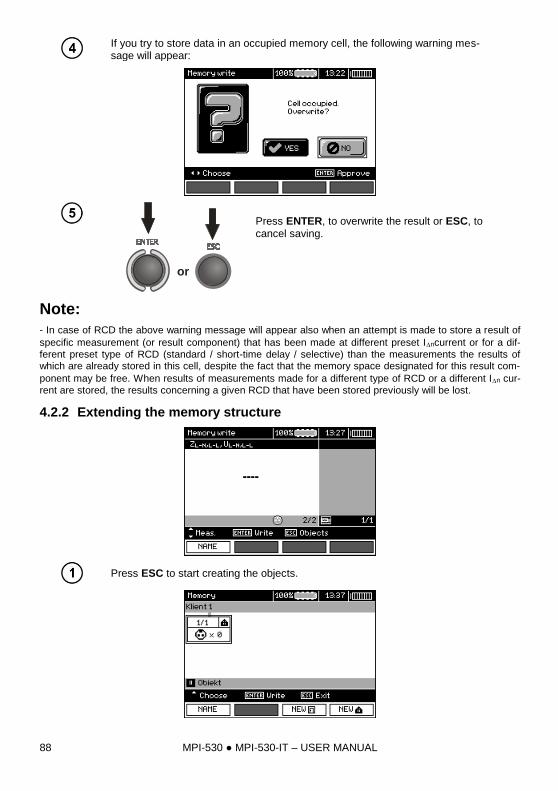
MPI-530 MPI-530-IT – USER MANUAL 88
If you try to store data in an occupied memory cell, the following warning mes-sage will appear:
or
Press ENTER, to overwrite the result or ESC, to cancel saving.
Note:
- In case of RCD the above warning message will appear also when an attempt is made to store a result of
specific measurement (or result component) that has been made at different preset Incurrent or for a dif-
ferent preset type of RCD (standard / short-time delay / selective) than the measurements the results of which are already stored in this cell, despite the fact that the memory space designated for this result com-
ponent may be free. When results of measurements made for a different type of RCD or a different In cur-
rent are stored, the results concerning a given RCD that have been stored previously will be lost.
4.2.2 Extending the memory structure
Press ESC to start creating the objects.
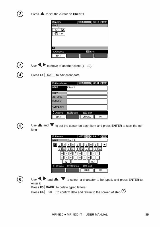
MPI-530 MPI-530-IT – USER MANUAL 89
Press to set the cursor on Client 1.
Use , to move to another client (1 - 10).
Press F1 to edit client data.
Use and to set the cursor on each item and press ENTER to start the ed-
iting.
Use , and , to select a character to be typed, and press ENTER to enter it.
Press F3 to delete typed letters.
Press F4 to confirm data and return to the screen of step .
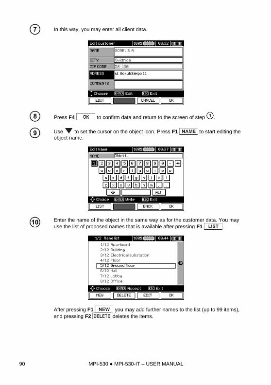
MPI-530 MPI-530-IT – USER MANUAL 90
In this way, you may enter all client data.
Press F4 to confirm data and return to the screen of step .
Use to set the cursor on the object icon. Press F1 to start editing the
object name.
Enter the name of the object in the same way as for the customer data. You may
use the list of proposed names that is available after pressing F1 .
After pressing F1 you may add further names to the list (up to 99 items),
and pressing F2 deletes the items.
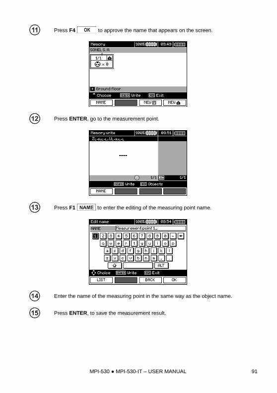
MPI-530 MPI-530-IT – USER MANUAL 91
Press F4 to approve the name that appears on the screen.
Press ENTER, go to the measurement point.
Press F1 to enter the editing of the measuring point name.
Enter the name of the measuring point in the same way as the object name.
Press ENTER, to save the measurement result.
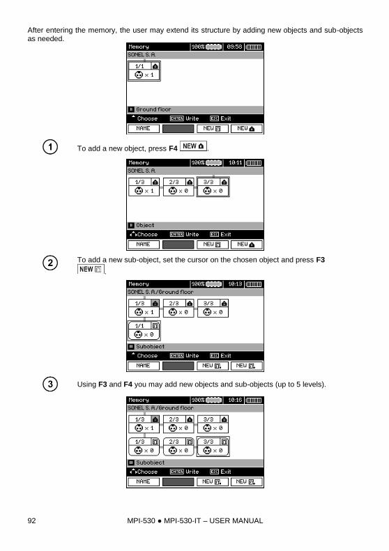
MPI-530 MPI-530-IT – USER MANUAL 92
After entering the memory, the user may extend its structure by adding new objects and sub-objects as needed.
To add a new object, press F4 .
To add a new sub-object, set the cursor on the chosen object and press F3
.
Using F3 and F4 you may add new objects and sub-objects (up to 5 levels).
MPI-530 MPI-530-IT – USER MANUAL 93
Note: - New objects (sub-objects in a level) are added on the right side of the object marked with the cursor (sub-object). - The screen displays only sub-objects belonging to the object (sub-object) indicated by the cursor. - Deleting objects and sub-objects is possible only in memory browse mode. - The name of an object, sub-object or measurement is possible in memory browse mode or after en-tering entry into the memory after a measurement.
4.3 Browsing and editing the memory
Set the rotary switch of function selection at
MEMposition.
Use and to select "MEMORY BROWSE
AND EDIT”.
Press ENTER push-button.
Last saved measurement in subobject 3, Level 1
MPI-530 MPI-530-IT – USER MANUAL 94
Use , and , to move between objects and sub-objects using the existing connectors.
Press F1 to enter the option for editing the name of object (sub-
object) and change it. Press F2 to delete a chosen object (sub-
object) with all its results.
After setting the cursor on the client, use ,
to move to next clients.
After selecting desired object (sub-object) press
ENTER.
The number of measuring point / number of all measuring points. The number of measurement type / number of all measurements types at that point.
Use , to change the measuring point.
Press F1 to enter the editing of the measuring point name and to
change it. Press F2 to delete a chosen measuring point with all its
results.
Press F3 and F4 to display all individual types of results for
a given point.
MPI-530 MPI-530-IT – USER MANUAL 95
4.4 Browsing the recorder memory
Set the rotary switch of function selection at
MEMposition.
Use and to select "LOGGER MEMORY
BROWSE".
Press ENTER push-button.
Use and to choose between browsing recorded results or single measurements.
Press ENTER push-button.
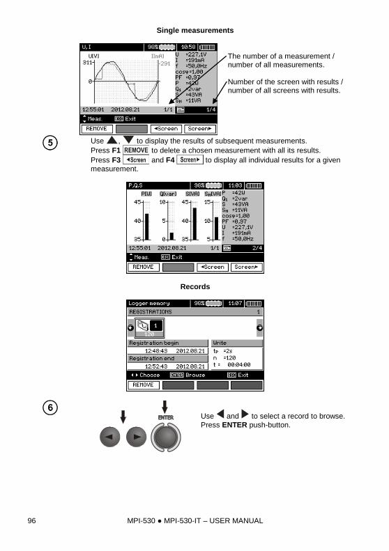
MPI-530 MPI-530-IT – USER MANUAL 96
Single measurements
The number of a measurement / number of all measurements. Number of the screen with results / number of all screens with results.
Use , to display the results of subsequent measurements.
Press F1 to delete a chosen measurement with all its results.
Press F3 and F4 to display all individual results for a given
measurement.
Records
Use and to select a record to browse.
Press ENTER push-button.
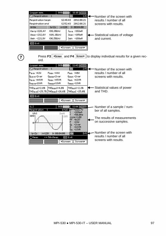
MPI-530 MPI-530-IT – USER MANUAL 97
Number of the screen with results / number of all screens with results. Statistical values of voltage and current.
Press F3 and F4 to display individual results for a given rec-
ord.
Number of the screen with results / number of all screens with results. Statistical values of power and THD.
Number of a sample / num-ber of all samples. The results of measurements on successive samples. Number of the screen with results / number of all screens with results.
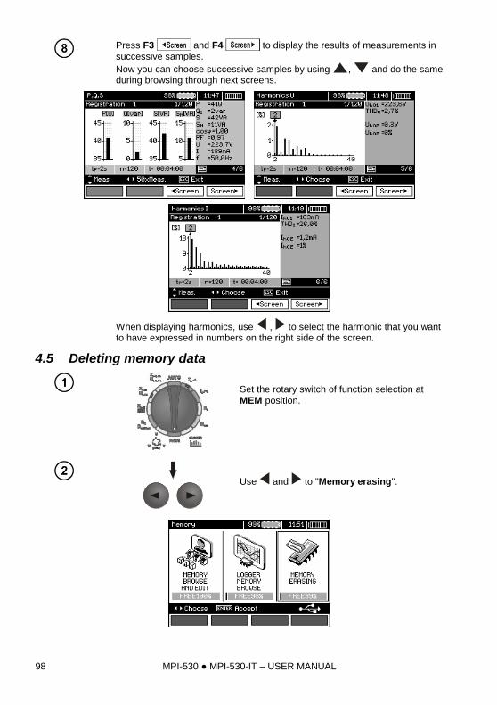
MPI-530 MPI-530-IT – USER MANUAL 98
Press F3 and F4 to display the results of measurements in
successive samples.
Now you can choose successive samples by using , and do the same during browsing through next screens.
When displaying harmonics, use , to select the harmonic that you want to have expressed in numbers on the right side of the screen.
4.5 Deleting memory data
Set the rotary switch of function selection at
MEM position.
Use and to "Memory erasing".
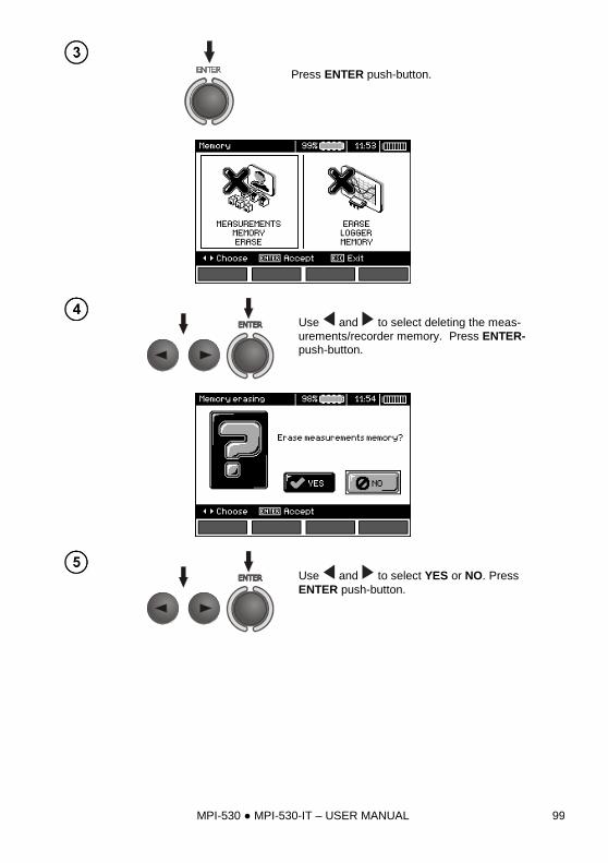
MPI-530 MPI-530-IT – USER MANUAL 99
Press ENTER push-button.
Use and to select deleting the meas-
urements/recorder memory. Press ENTER-push-button.
Use and to select YES or NO. Press
ENTER push-button.
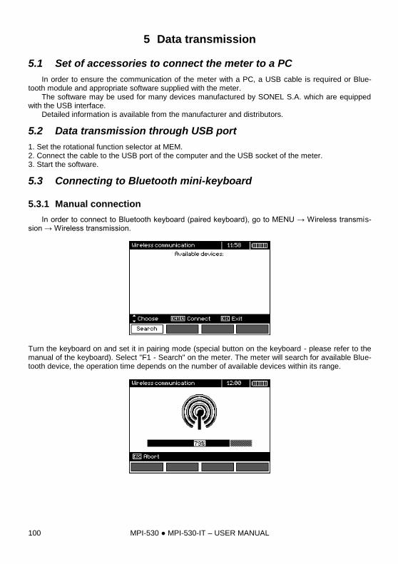
MPI-530 MPI-530-IT – USER MANUAL 100
5 Data transmission
5.1 Set of accessories to connect the meter to a PC
In order to ensure the communication of the meter with a PC, a USB cable is required or Blue-tooth module and appropriate software supplied with the meter. The software may be used for many devices manufactured by SONEL S.A. which are equipped with the USB interface. Detailed information is available from the manufacturer and distributors.
5.2 Data transmission through USB port
1. Set the rotational function selector at MEM. 2. Connect the cable to the USB port of the computer and the USB socket of the meter. 3. Start the software.
5.3 Connecting to Bluetooth mini-keyboard
5.3.1 Manual connection
In order to connect to Bluetooth keyboard (paired keyboard), go to MENU → Wireless transmis-sion → Wireless transmission.
Turn the keyboard on and set it in pairing mode (special button on the keyboard - please refer to the manual of the keyboard). Select "F1 - Search" on the meter. The meter will search for available Blue-tooth device, the operation time depends on the number of available devices within its range.
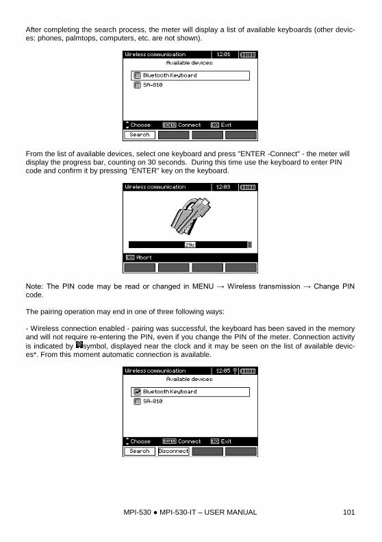
MPI-530 MPI-530-IT – USER MANUAL 101
After completing the search process, the meter will display a list of available keyboards (other devic-es: phones, palmtops, computers, etc. are not shown).
From the list of available devices, select one keyboard and press "ENTER -Connect" - the meter will display the progress bar, counting on 30 seconds. During this time use the keyboard to enter PIN code and confirm it by pressing "ENTER" key on the keyboard.
Note: The PIN code may be read or changed in MENU → Wireless transmission → Change PIN code. The pairing operation may end in one of three following ways: - Wireless connection enabled - pairing was successful, the keyboard has been saved in the memory and will not require re-entering the PIN, even if you change the PIN of the meter. Connection activity
is indicated by symbol, displayed near the clock and it may be seen on the list of available devic-es*. From this moment automatic connection is available.
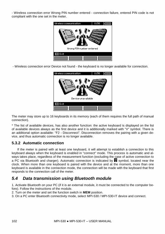
MPI-530 MPI-530-IT – USER MANUAL 102
- Wireless connection error Wrong PIN number entered - connection failure, entered PIN code is not compliant with the one set in the meter.
- Wireless connection error Device not found - the keyboard is no longer available for connection.
The meter may store up to 16 keyboards in its memory (each of them requires the full path of manual connection).
* The list of available devices, has also another function: the active keyboard is displayed on the list of available devices always as the first device and it is additionally marked with "V" symbol. There is an additional option available: "F2 - Disconnect". Disconnection removes the pairing with a given de-vice, and thus automatic connection is no longer available.
5.3.2 Automatic connection
If the meter is paired with at least one keyboard, it will attempt to establish a connection to this keyboard always when the keyboard is enabled in "connect" mode. This process is automatic and al-ways takes place, regardless of the measurement function (excluding the case of active connection to
a PC via Bluetooth and charger). Automatic connection is indicated by symbol, located near the clock. When more than one keyboard is paired with the device and at the moment, more than one keyboard is available in the connection mode, the connection will be made with the keyboard that first responds to the connection call of the meter.
5.4 Data transmission using Bluetooth module
1. Activate Bluetooth on your PC (if it is an external module, it must be connected to the computer be-fore). Follow the instructions of the module.
2. Turn on the meter and set the function switch in MEM position. 3. On a PC enter Bluetooth connectivity mode, select MPI-530 / MPI-530-IT device and connect.
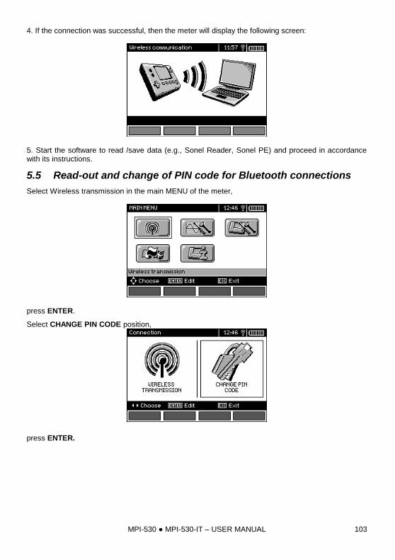
MPI-530 MPI-530-IT – USER MANUAL 103
4. If the connection was successful, then the meter will display the following screen:
5. Start the software to read /save data (e.g., Sonel Reader, Sonel PE) and proceed in accordance with its instructions.
5.5 Read-out and change of PIN code for Bluetooth connections
Select Wireless transmission in the main MENU of the meter,
press ENTER.
Select CHANGE PIN CODE position,
press ENTER.
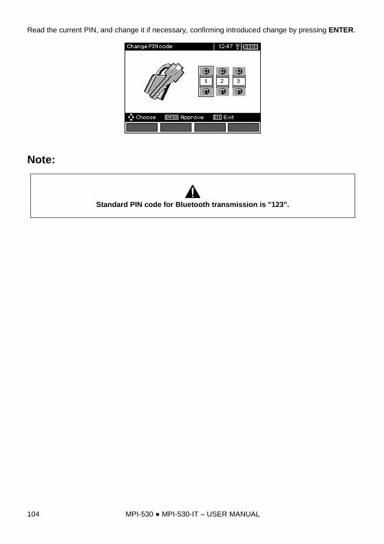
MPI-530 MPI-530-IT – USER MANUAL 104
Read the current PIN, and change it if necessary, confirming introduced change by pressing ENTER.
Note:
Standard PIN code for Bluetooth transmission is "123".
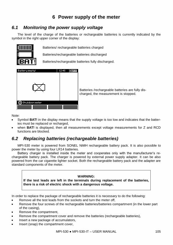
MPI-530 MPI-530-IT – USER MANUAL 105
6 Power supply of the meter
6.1 Monitoring the power supply voltage
The level of the charge of the batteries or rechargeable batteries is currently indicated by the symbol in the right upper corner of the display:
Batteries/ rechargeable batteries charged
Batteries/rechargeable batteries discharged
Batteries/rechargeable batteries fully discharged.
Batteries /rechargeable batteries are fully dis-charged, the measurement is stopped.
Note:
Symbol BAT! in the display means that the supply voltage is too low and indicates that the batter-ies must be replaced or recharged,
when BAT! is displayed, then all measurements except voltage measurements for Z and RCD functions are blocked.
6.2 Replacing batteries (rechargeable batteries)
MPI-530 meter is powered from SONEL NiMH rechargeable battery pack. It is also possible to power the meter by using four LR14 batteries.
Battery charger is installed inside the meter and cooperates only with the manufacturer’s re-chargeable battery pack. The charger is powered by external power supply adapter. It can be also powered from the car cigarette lighter socket. Both the rechargeable battery pack and the adapter are standard components of the meter.
WARNING:
If the test leads are left in the terminals during replacement of the batteries,
there is a risk of electric shock with a dangerous voltage.
In order to replace the package of rechargeable batteries it is necessary to do the following:
Remove all the test leads from the sockets and turn the meter off,
Remove the four screws of the rechargeable batteries/batteries compartment (in the lower part of the casing),
Remove the compartment,
Remove the compartment cover and remove the batteries (rechargeable batteries),
Insert a new package of accumulators,
Insert (snap) the compartment cover,
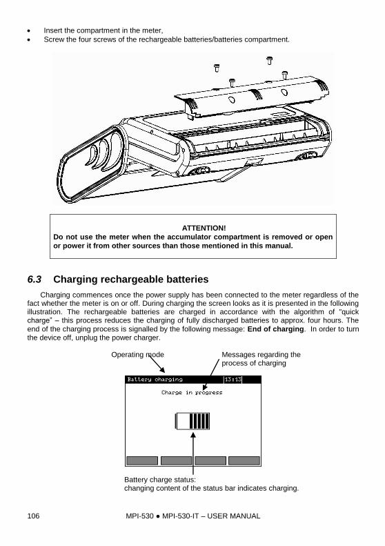
MPI-530 MPI-530-IT – USER MANUAL 106
Insert the compartment in the meter,
Screw the four screws of the rechargeable batteries/batteries compartment.
ATTENTION!
Do not use the meter when the accumulator compartment is removed or open
or power it from other sources than those mentioned in this manual.
6.3 Charging rechargeable batteries
Charging commences once the power supply has been connected to the meter regardless of the fact whether the meter is on or off. During charging the screen looks as it is presented in the following illustration. The rechargeable batteries are charged in accordance with the algorithm of "quick charge” – this process reduces the charging of fully discharged batteries to approx. four hours. The
end of the charging process is signalled by the following message: End of charging. In order to turn the device off, unplug the power charger.
Operating mode Messages regarding the process of charging
Battery charge status: changing content of the status bar indicates charging.
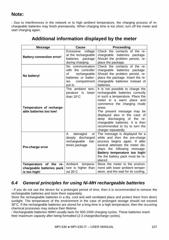
MPI-530 MPI-530-IT – USER MANUAL 107
Note: - Due to interferences in the network or to high ambient temperature, the charging process of re-chargeable batteries may finish prematurely. When charging time is too short, turn off the meter and start charging again.
Additional information displayed by the meter
Message Cause Proceeding
Battery connection error!
Excessive voltage at the rechargeable batteries package during charging.
Check the contacts of the re-chargeable batteries package. Should the problem persist, re-place the package.
No battery!
No communication with the controller of rechargeable batteries or batter-ies compartment put in.
Check the contacts of the re-chargeable batteries package. Should the problem persist, re-place the package. Insert the re-chargeable batteries instead of batteries.
Temperature of recharge-
able batteries too low!
The ambient tem-perature is lower
than 10C
It is not possible to charge the rechargeable batteries correctly in such a temperature. Place the meter in a warm place and commence the charging mode anew. The present message may be displayed also in the case of deep discharging of the re-chargeable batteries. It is then recommended to try to turn the charger repeatedly.
Pre-charge error
A damaged or deeply discharged rechargeable bat-teries package
The message is displayed for a while and then the pre-charge process begins again. If after several attempts the meter dis-plays the following message:
Battery temperature too high! the the battery pack must be re-placed.
Temperature of the re-
chargeable batteries pack
is too high!
Ambient tempera-ture is higher than
od 35C
Move the meter to the environ-ment with lower ambient temper-ature, and the wait for its cooling.
6.4 General principles for using Ni-MH rechargeable batteries
- If you do not use the device for a prolonged period of time, then it is recommended to remove the rechargeable batteries and store them separately. Store the rechargeable batteries in a dry, cool and well ventilated place and protect them from direct sunlight. The temperature of the environment in the case of prolonged storage should not exceed 30°C. If the rechargeable batteries are stored for a long time in a high temperature, then the occurring chemical processes may reduce their lifetime. - Rechargeable batteries NiMH usually lasts for 500-1000 charging cycles. These batteries reach their maximum capacity after being formatted (2-3 charge/discharge cycles).
MPI-530 MPI-530-IT – USER MANUAL 108
The most important factor which influences the lifetime of rechargeable batteries is the level of their discharge. The deeper the discharge level of the batteries, the shorter their lifetime. - The memory effect is limited in the case of NiMH batteries. These batteries may be charged at any point with no serious consequences. It is however, that every few cycles, they are completely discharged. - During storage of Ni-MH rechargeable batteries they are discharged at the rate of approximately 30% per month. Keeping rechargeable batteries at high temperatures may accelerate this process even 100%. In order to prevent excessive discharge of rechargeable batteries, after which it would be necessary to format them, it is recommended to charge them from time to time (even if they are not used). - Modern fast chargers detect both too low and too high a temperature of rechargeable batteries and react to the situation adequately. Too low temperature should prevent starting the process of charg-ing, which might irreparably damage rechargeable batteries. An increase of the temperature of the rechargeable batteries is a signal to stop charging and is a typical phenomenon. However charging at a high ambient temperature apart from reducing batteries' lifetime causes an accelerated increase of their temperature and the result is that the batteries are not charged to their full capacity. - Please note that when the batteries are charged with a fast-charger they are charged only to approx. 80% of their capacity - better results can be achieved by continuing charging: the charger enters trick-le-charging mode and during the next few hours batteries are charged to their full capacity. - Do not charge or use rechargeable batteries in extreme temperatures. Extreme temperatures re-duce the lifetime of batteries and rechargeable batteries. Avoid placing devices powered by re-chargeable batteries in very hot environments. The nominal working temperature must be absolutely observed.
7 Cleaning and maintenance
ATTENTION!
Use only the maintenance methods specified by the manufacturer in this
manual.
The casing of the meter may be cleaned with a soft, damp cloth using all-purpose detergents. Do not use any solvents or cleaning agents which might scratch the casing (powders, pastes, etc.). Clean the probe with water and dry it. Before the probe is stored for a prolonged period of time it is recommended to grease it with any machine lubricant. The reels and test leads should be cleaned with water and detergents, and then dried. The electronic system of the meter does not require maintenance.
8 Storage
In the case of storage of the device, the following recommendations must be observed:
Disconnect all the test leads from the meter.
Clean the meter and all its accessories thoroughly.
Wind the long test leads onto the reels.
In the case the meter is to be stored for a prolonged period of time, the batteries must be re-moved from the device.
In order to prevent a total discharge of the rechargeable batteries in the case of a prolonged stor-age, charge them from time to time.
MPI-530 MPI-530-IT – USER MANUAL 109
9 Dismantling and utilisation
Worn-out electric and electronic equipment should be gathered selectively, i.e. it must not be placed with waste of another kind.
Worn-out electronic equipment should be sent to a collection point in accordance with the law of waste electrical and electronic equipment.
Before the equipment is sent to a collection point, do not dismantle any elements. Observe the local regulations concerning disposal of packages and used batteries/rechargeable
batteries.
10 Technical specifications
10.1 Basic data
Abbreviation "m.v." used in the specification of basic uncertainty means standard measured value
Measurement of alternating voltages (True RMS)
Range Resolution Basic uncertainty
0.0 V...299.9 V 0.1 V (2 % m.v. + 4 digits)
300 V…500 V 1 V (2 % m.v. + 2 digits)
Frequency range: 45...65Hz
Measurement of frequency
Range Resolution Basic uncertainty
45.0 Hz...65.0 Hz 0.1 Hz (0.1 % m.v. + 1 digit)
Voltage range: 50 ... 500V
Recorder
Measurement of current (True RMS)
Clamps C-6
Range Resolution Basic uncertainty*
0.0 mA ... 99.9 mA 0.1 mA (5 % m.v. + 3 digits)
100 mA...999 mA 1 mA
1.00 A...9.99 A 0.01 A (5 % m.v. + 5 digits)
Clamps C-3
Range Resolution Basic uncertainty*
0.0 mA ... 99.9 mA 0.1 mA (5 % m.v. + 3 digits)
100 mA...999 mA 1 mA
1.00 A...9.99 A 0.01 A
(5 % m.v. + 5 digits) 10.0 A...99.9 A 0.1 A
100 A...999 A 1 A
MPI-530 MPI-530-IT – USER MANUAL 110
Clamps F-1, F-2, F-3
Range Resolution Basic uncertainty *
1.00 A...9.99 A 0.01 A
(0,1 % Inom + 2 digits) 10.0 A...99.9 A 0.1 A
100 A...999 A 1 A
1.00 kA...3.00 kA 0.01 kA
Inom = 3000 A * - Additionally take into account the uncertainty of current clamps.
Measurement of active power P, reactive power Q1 and apparent power S and cosφ
Range
[W], [VA], [var]
Resolution
[W], [VA], [var]
Basic uncertainty
(with regard to apparent power S) *)
0…999 1 ±(7 % m.v. + 3 digits)
1.00 k…9.99 k 0.01 k
±(7 % m.v. + 3 digits) 10.0 k…99.9 k 0.1 k
100 k…999 k 1 k
1.00 M…1.50 M 0.01 M
Voltage range: 0 V ... 500 V
Current range: 0 A...1000 A (3000 A)
Rated mains frequency fn: 50 Hz, 60 Hz
Number of phases of the circuit tested: 1
Display range of cosφ: 0.00..1.00 (resolution 0.01) *) U: 50 V…500 V, I: 10 mA…3000 A (depending on the type of clamps), error introduced by the
current clamps should be taken into account
Measuring voltage harmonics
Range Resolution No. of harmonic Basic uncertainty
0.0 V...500 V 0,1 (1*) V 1.2,...15 ±(5 % m.v. + 3 digits)
16,...40 ±(5 % m.v. + 10 digits)
* from 300 V to 500 V
Additionally h02…h40 values are displayed as a percent of h01 (up to 999 %).
No measurement for DC component.
Measuring current harmonics
Range Resolution No. of harmonic Basic uncertainty **
0.0 A...1000 A* It results follows
from the ranges of measurement I
1.2,...15 ±(5 % m.v. + 3 digits)
16,...40 ±(5 % m.v. + 10 digits)
* - For clamps C-3, for C-6 -10 A, for clamps of F series, up to 3000 A. ** - Additionally take into account the uncertainty of current clamps.
Additionally h02…h40 values are displayed as a percent of h01 (up to 999 %).
No measurement for DC component.
THD (in relation to the first harmonic)
Resolution Basic uncertainty
Voltage THD-F (h = 2…40)
0.0 ... 999.9 % for URMS ≥ 1 % Unom
0.1 % 5 %
current THD-F (h = 2...40)
0.0 ... 999.9 % for IRMS ≥ 1 % Inom
0.1 % 5 % *
* - Additionally take into account the uncertainty of current clamps.
MPI-530 MPI-530-IT – USER MANUAL 111
Measurement of fault loop impedance ZL-PE, ZL-N, ZL-L
Measurement of fault loop impedance ZS Test range according to IEC 61557-3:
Test lead Test range ZS
1.2 m 0.130 ...1999.9
5 m 0.170 ...1999.9
10 m 0.210 ...1999.9
20 m 0.290 ...1999.9
WS-03, WS-04 0.190 ...1999.9
Display range:
Display range Resolution Basic uncertainty
0.000 ...19.999 0.001 (5 % m.v. + 0,03 )
20.00 ...199.99 0.01 (5 % m.v. + 0,3 )
200.0 ...1999,9 0.1 (5 % m.v. + 3 )
Rated operating voltage UnL-N/ UnL-L: 110/190 V, 115/200 V, 127/220 V, 220/380 V, 230/400 V, 240/415 V
Operating voltage range: 95 V…270 V (for ZL-PE and ZL-N) and 95 V…440 V (for ZL-L)
Rated mains frequency fn: 50 Hz, 60 Hz
Operating frequency range: 45 Hz…65 Hz
Maximum test current (for 415 V): 41.5 A (10 ms)
Control of correctness of PE terminal connection by means of a touch electrode
Indications of fault loop resistance RS and fault loop reactance XS
Display range Resolution Basic uncertainty
0 ..19.999 0.001 (5 % + 0.05 of ZS value
Calculated and displayed for ZS<20
Indications of short-circuit current Ik Test range according to IEC 61557-3 can be calculated on the basis of test ranges for ZS and nomi-nal voltages.
Display range Resolution Basic uncertainty
0.055 A …1.999 A 0.001 A
Calculated on the basis of uncertainty for
fault loop
2.00 A...19.99 A 0.01 A
20.0 A...199.9 A 0.1 A
200 A...1999 A 1 A
2.00 kA...19.99 kA 0.01 kA
20.0 kA …40.0 kA 0.1 kA
Prospective fault current calculated and displayed by the meter may slightly differ from the val-ue calculated by the user with a calculator, basing on the displayed value of the impedance, because the meter calculates the current from unrounded value of fault loop impedance (which is used for displaying). As the correct value, consider Ik current value, displayed by the meter or by firmware.
MPI-530 MPI-530-IT – USER MANUAL 112
Measurement of fault loop impedance ZL-PE RCD (without triggering of RCD)
Measurement of fault loop impedance ZS
Test range according to IEC 61557-3: 0.50 …1999 for 1.2m leads, WS-03 and WS-04 oraz
0.51 ...1999 for 5m, 10m and 20m leads
Display range Resolution Basic uncertainty
0 ...19.99 0.01 (6 % m.v. + 10 digits)
20.0 ...199.9 0.1 (6 % m.v. + 5 digits)
200 ...1999 1
It will not trip RCD's of IΔn ≥ 30 mA
Rated operating voltage Un: 110 V, 115 V, 127 V, 220 V, 230 V, 240 V
Operating voltage range: 95 V…270 V
Rated mains frequency fn: 50 Hz, 60 Hz
Operating frequency range: 45 Hz…65 Hz
Control of correctness of PE terminal connection by means of a touch electrode
Indications of fault loop resistance RS and fault loop reactance XS
Display range Resolution Basic uncertainty
0 ...19.99 0.01 (6 % + 10 digits) of ZS va-
lue
Calculated and displayed for ZS<20
Indications of short-circuit current Ik Test range according to IEC 61557-3 can be calculated on the basis of test ranges for ZS and nomi-nal voltages.
Display range Resolution Basic uncertainty
0.055 A …1.999 A 0.001 A
Calculated on the basis of uncertainty for fault loop
2.00 A...19.99 A 0.01 A
20.0 A...199.9 A 0.1 A
200 A...1999 A 1 A
2.00 kA...19.99 kA 0.0 1kA
20.0 kA …40.0 kA 0.1 kA
Prospective fault current calculated and displayed by the meter may slightly differ from the val-ue calculated by the user with a calculator, basing on the displayed value of the impedance, because the meter calculates the current from unrounded value of fault loop impedance (which is used for displaying). As the correct value, consider Ik current value, displayed by the meter or by firmware.
Measurement of parameters of RCD
Measurement of RCD types: AC, A, B, B+, F
Rated operating voltage Un: 110 V, 115 V, 127 V, 220 V, 230 V, 240 V
Operating voltage range: 95 V…270 V
Rated mains frequency fn: 50 Hz, 60 Hz
Operating frequency range: 45 Hz…65 Hz
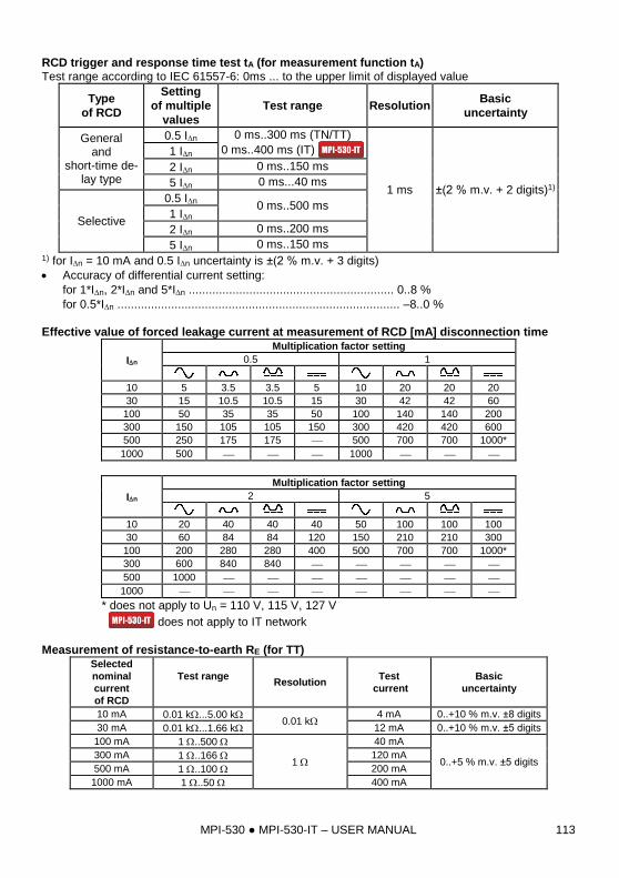
MPI-530 MPI-530-IT – USER MANUAL 113
RCD trigger and response time test tA (for measurement function tA) Test range according to IEC 61557-6: 0ms ... to the upper limit of displayed value
Type
of RCD
Setting
of multiple
values
Test range Resolution Basic
uncertainty
General and
short-time de-lay type
0.5 In 0 ms..300 ms (TN/TT)
0 ms..400 ms (IT)
1 ms ±(2 % m.v. + 2 digits)1)
1 In
2 In 0 ms..150 ms
5 In 0 ms...40 ms
Selective
0.5 In 0 ms..500 ms
1 In
2 In 0 ms..200 ms
5 In 0 ms..150 ms 1) for In = 10 mA and 0.5 In uncertainty is ±(2 % m.v. + 3 digits)
Accuracy of differential current setting:
for 1*In, 2*In and 5*In ............................................................. 0..8 %
for 0.5*In .................................................................................... –8..0 %
Effective value of forced leakage current at measurement of RCD [mA] disconnection time
In
Multiplication factor setting
0.5 1
10 5 3.5 3.5 5 10 20 20 20
30 15 10.5 10.5 15 30 42 42 60
100 50 35 35 50 100 140 140 200
300 150 105 105 150 300 420 420 600
500 250 175 175 500 700 700 1000*
1000 500 1000
In
Multiplication factor setting
2 5
10 20 40 40 40 50 100 100 100
30 60 84 84 120 150 210 210 300
100 200 280 280 400 500 700 700 1000*
300 600 840 840
500 1000
1000
* does not apply to Un = 110 V, 115 V, 127 V
does not apply to IT network
Measurement of resistance-to-earth RE (for TT) Selected
nominal
current
of RCD
Test range
Resolution
Test
current
Basic
uncertainty
10 mA 0.01 k...5.00 k 0.01 k
4 mA 0..+10 % m.v. ±8 digits
30 mA 0.01 k...1.66 k 12 mA 0..+10 % m.v. ±5 digits
100 mA 1 ..500
1
40 mA
0..+5 % m.v. ±5 digits 300 mA 1 ..166 120 mA
500 mA 1 ..100 200 mA
1000 mA 1 ..50 400 mA
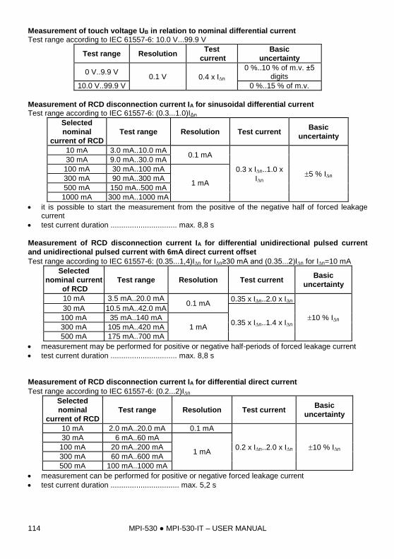
MPI-530 MPI-530-IT – USER MANUAL 114
Measurement of touch voltage UB in relation to nominal differential current Test range according to IEC 61557-6: 10.0 V...99.9 V
Test range Resolution Test
current
Basic
uncertainty
0 V..9.9 V 0.1 V 0.4 x In
0 %..10 % of m.v. ±5 digits
10.0 V..99.9 V 0 %..15 % of m.v.
Measurement of RCD disconnection current IA for sinusoidal differential current Test range according to IEC 61557-6: (0.3...1.0)IΔn
Selected
nominal
current of RCD
Test range Resolution Test current Basic
uncertainty
10 mA 3.0 mA..10.0 mA 0.1 mA
0.3 x In..1.0 x
In 5 % In
30 mA 9.0 mA..30.0 mA
100 mA 30 mA..100 mA
1 mA 300 mA 90 mA..300 mA
500 mA 150 mA..500 mA
1000 mA 300 mA..1000 mA
it is possible to start the measurement from the positive of the negative half of forced leakage current
test current duration ............................... max. 8,8 s
Measurement of RCD disconnection current IA for differential unidirectional pulsed current
and unidirectional pulsed current with 6mA direct current offset
Test range according to IEC 61557-6: (0.35...1,4)In for In≥30 mA and (0.35...2)In for In=10 mA
Selected
nominal current
of RCD
Test range Resolution Test current Basic
uncertainty
10 mA 3.5 mA..20.0 mA 0.1 mA
0.35 x In..2.0 x In
10 % In
30 mA 10.5 mA..42.0 mA
0.35 x In..1.4 x In 100 mA 35 mA..140 mA
1 mA 300 mA 105 mA..420 mA
500 mA 175 mA..700 mA
measurement may be performed for positive or negative half-periods of forced leakage current
test current duration ............................... max. 8,8 s
Measurement of RCD disconnection current IA for differential direct current
Test range according to IEC 61557-6: (0.2...2)In
Selected
nominal
current of RCD
Test range Resolution Test current Basic
uncertainty
10 mA 2.0 mA..20.0 mA 0.1 mA
0.2 x In..2.0 x In 10 % In
30 mA 6 mA..60 mA
1 mA 100 mA 20 mA..200 mA
300 mA 60 mA..600 mA
500 mA 100 mA..1000 mA
measurement can be performed for positive or negative forced leakage current
test current duration ................................ max. 5,2 s
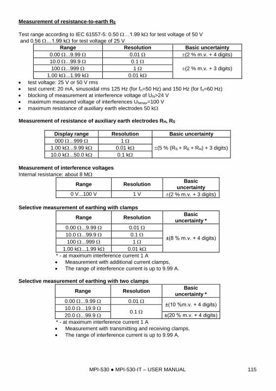
MPI-530 MPI-530-IT – USER MANUAL 115
Measurement of resistance-to-earth RE
Test range according to IEC 61557-5: 0.50 …1.99 k for test voltage of 50 V
and 0.56 …1.99 k for test voltage of 25 V
Range Resolution Basic uncertainty
0.00 ...9.99 0.01 (2 % m.v. + 4 digits)
10.0 ...99.9 0.1
(2 % m.v. + 3 digits) 100 ...999 1
1.00 k...1.99 k 0.01 k
test voltage: 25 V or 50 V rms
test current: 20 mA, sinusoidal rms 125 Hz (for fn=50 Hz) and 150 Hz (for fn=60 Hz)
blocking of measurement at interference voltage of UN>24 V
maximum measured voltage of interferences UNmax=100 V
maximum resistance of auxiliary earth electrodes 50 k
Measurement of resistance of auxiliary earth electrodes RH, RS
Display range Resolution Basic uncertainty
000 ...999 1
(5 % (RS + RE + RH) + 3 digits) 1.00 k...9.99 k 0.01 k
10.0 k...50.0 k 0.1 k
Measurement of interference voltages
Internal resistance: about 8 M
Range Resolution Basic
uncertainty
0 V...100 V 1 V (2 % m.v. + 3 digits)
Selective measurement of earthing with clamps
Range Resolution Basic
uncertainty *
0.00 ...9.99 0.01
±(8 % m.v. + 4 digits) 10.0 ...99.9 0.1
100 ...999 1
1.00 k...1.99 k 0.01 k
* - at maximum interference current 1 A
Measurement with additional current clamps,
The range of interference current is up to 9.99 A.
Selective measurement of earthing with two clamps
Range Resolution Basic
uncertainty *
0.00 ...9.99 0.01 ±(10 %m.v. + 4 digits)
10.0 ...19.9 0.1
20.0 ...99.9 ±(20 % m.v. + 4 digits)
* - at maximum interference current 1 A
Measurement with transmitting and receiving clamps.
The range of interference current is up to 9.99 A.
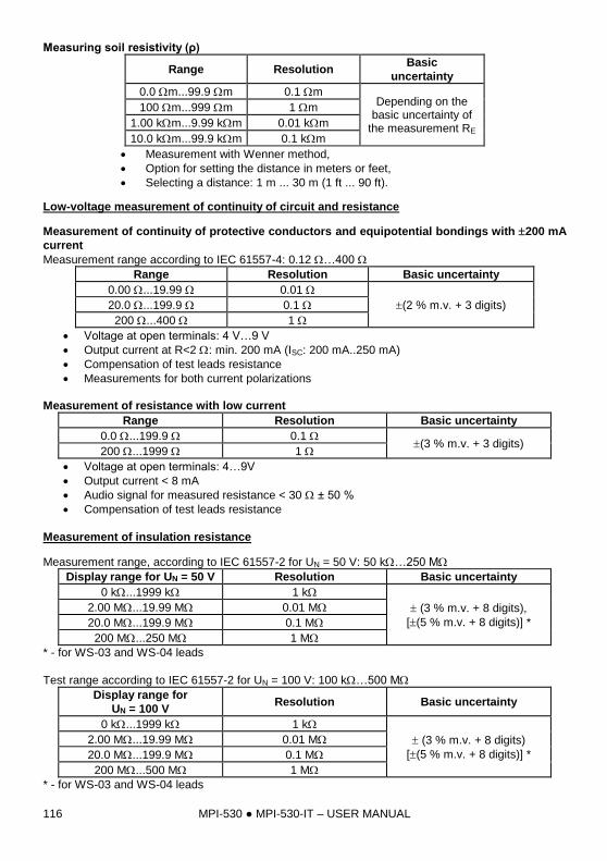
MPI-530 MPI-530-IT – USER MANUAL 116
Measuring soil resistivity (ρ)
Range Resolution Basic
uncertainty
0.0 m...99.9 m 0.1 m Depending on the
basic uncertainty of the measurement RE
100 m...999 m 1 m
1.00 km...9.99 km 0.01 km
10.0 km...99.9 km 0.1 km
Measurement with Wenner method,
Option for setting the distance in meters or feet,
Selecting a distance: 1 m ... 30 m (1 ft ... 90 ft).
Low-voltage measurement of continuity of circuit and resistance
Measurement of continuity of protective conductors and equipotential bondings with 200 mA
current
Measurement range according to IEC 61557-4: 0.12 …400
Range Resolution Basic uncertainty
0.00 ...19.99 0.01
(2 % m.v. + 3 digits) 20.0 ...199.9 0.1
200 ...400 1
Voltage at open terminals: 4 V…9 V
Output current at R<2 : min. 200 mA (ISC: 200 mA..250 mA)
Compensation of test leads resistance
Measurements for both current polarizations
Measurement of resistance with low current
Range Resolution Basic uncertainty
0.0 ...199.9 0.1 (3 % m.v. + 3 digits)
200 ...1999 1
Voltage at open terminals: 4…9V
Output current < 8 mA
Audio signal for measured resistance < 30 ± 50 %
Compensation of test leads resistance
Measurement of insulation resistance
Measurement range, according to IEC 61557-2 for UN = 50 V: 50 k…250 M
Display range for UN = 50 V Resolution Basic uncertainty
0 k...1999 k 1 k
(3 % m.v. + 8 digits),
[(5 % m.v. + 8 digits)] *
2.00 M...19.99 M 0.01 M
20.0 M...199.9 M 0.1 M
200 M...250 M 1 M
* - for WS-03 and WS-04 leads
Test range according to IEC 61557-2 for UN = 100 V: 100 k…500 M
Display range for
UN = 100 V Resolution Basic uncertainty
0 k...1999 k 1 k
(3 % m.v. + 8 digits)
[(5 % m.v. + 8 digits)] *
2.00 M...19.99 M 0.01 M
20.0 M...199.9 M 0.1 M
200 M...500 M 1 M
* - for WS-03 and WS-04 leads
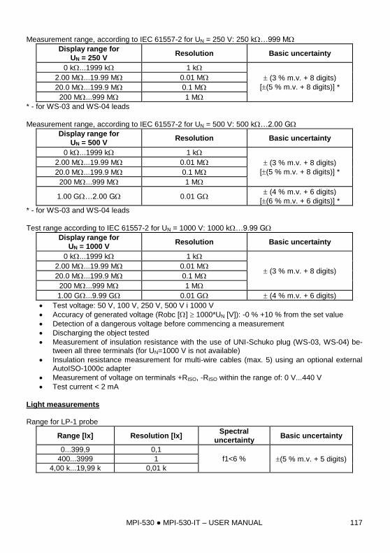
MPI-530 MPI-530-IT – USER MANUAL 117
Measurement range, according to IEC 61557-2 for UN = 250 V: 250 k…999 M
Display range for
UN = 250 V Resolution Basic uncertainty
0 k...1999 k 1 k
(3 % m.v. + 8 digits)
[(5 % m.v. + 8 digits)] *
2.00 M...19.99 M 0.01 M
20.0 M...199.9 M 0.1 M
200 M...999 M 1 M
* - for WS-03 and WS-04 leads
Measurement range, according to IEC 61557-2 for UN = 500 V: 500 k…2.00 G
Display range for
UN = 500 V Resolution Basic uncertainty
0 k...1999 k 1 k
(3 % m.v. + 8 digits)
[(5 % m.v. + 8 digits)] *
2.00 M...19.99 M 0.01 M
20.0 M...199.9 M 0.1 M
200 M...999 M 1 M
1.00 G…2.00 G 0.01 G (4 % m.v. + 6 digits)
[(6 % m.v. + 6 digits)] *
* - for WS-03 and WS-04 leads
Test range according to IEC 61557-2 for UN = 1000 V: 1000 k…9.99 G
Display range for
UN = 1000 V Resolution Basic uncertainty
0 k...1999 k 1 k
(3 % m.v. + 8 digits) 2.00 M...19.99 M 0.01 M
20.0 M...199.9 M 0.1 M
200 M...999 M 1 M
1.00 G...9.99 G 0.01 G (4 % m.v. + 6 digits)
Test voltage: 50 V, 100 V, 250 V, 500 V i 1000 V
Accuracy of generated voltage (Robc [] 1000*UN [V]): -0 % +10 % from the set value
Detection of a dangerous voltage before commencing a measurement
Discharging the object tested
Measurement of insulation resistance with the use of UNI-Schuko plug (WS-03, WS-04) be-tween all three terminals (for UN=1000 V is not available)
Insulation resistance measurement for multi-wire cables (max. 5) using an optional external AutoISO-1000c adapter
Measurement of voltage on terminals +RISO, -RISO within the range of: 0 V...440 V
Test current < 2 mA
Light measurements Range for LP-1 probe
Range [lx] Resolution [lx] Spectral
uncertainty Basic uncertainty
0...399,9 0,1
f1<6 % (5 % m.v. + 5 digits) 400...3999 1
4,00 k...19,99 k 0,01 k
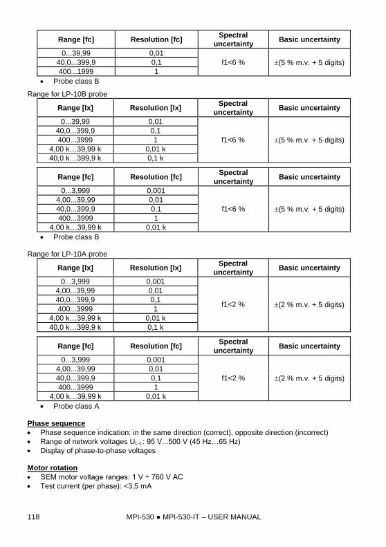
MPI-530 MPI-530-IT – USER MANUAL 118
Range [fc] Resolution [fc] Spectral
uncertainty Basic uncertainty
0...39,99 0,01
f1<6 % (5 % m.v. + 5 digits) 40,0...399,9 0,1
400...1999 1
Probe class B
Range for LP-10B probe
Range [lx] Resolution [lx] Spectral
uncertainty Basic uncertainty
0...39,99 0,01
f1<6 % (5 % m.v. + 5 digits)
40,0...399,9 0,1
400...3999 1
4,00 k…39,99 k 0,01 k
40,0 k…399,9 k 0,1 k
Range [fc] Resolution [fc] Spectral
uncertainty Basic uncertainty
0...3,999 0,001
f1<6 % (5 % m.v. + 5 digits)
4,00...39,99 0,01
40,0...399,9 0,1
400...3999 1
4,00 k…39,99 k 0,01 k
Probe class B Range for LP-10A probe
Range [lx] Resolution [lx] Spectral
uncertainty Basic uncertainty
0...3,999 0,001
f1<2 % (2 % m.v. + 5 digits)
4,00...39,99 0,01
40,0...399,9 0,1
400...3999 1
4,00 k…39,99 k 0,01 k
40,0 k…399,9 k 0,1 k
Range [fc] Resolution [fc] Spectral
uncertainty Basic uncertainty
0...3,999 0,001
f1<2 % (2 % m.v. + 5 digits)
4,00...39,99 0,01
40,0...399,9 0,1
400...3999 1
4,00 k…39,99 k 0,01 k
Probe class A
Phase sequence
Phase sequence indication: in the same direction (correct), opposite direction (incorrect)
Range of network voltages UL-L: 95 V...500 V (45 Hz…65 Hz)
Display of phase-to-phase voltages
Motor rotation
SEM motor voltage ranges: 1 V ÷ 760 V AC
Test current (per phase): <3,5 mA
MPI-530 MPI-530-IT – USER MANUAL 119
10.2 Other technical data
a) type of insulation ..................................................... double, EN 61010-1 and IEC 61557 compliant b) measurement category ............................................. IV 300 V (III 600 V) according to EN 61010-1 c) degree of housing protection acc. to EN 60529 ....................................................................... IP54 d) power supply of the meter ..............................................................................................................
alkaline batteries 4x1.5 V LR14 (C) or package of rechargeable batteries SONEL NiMH 4.8 V 4.2 Ah e) parameters of AC adapter for the battery charge ............................... 100 V…240 V, 50 Hz…60 Hz f) dimensions ..........................................................................................288 mm x 223 mm x 75 mm g) weight of the meter with batteries ............................................................................. approx. 2.5 kg
h) storage temperature ............................................................................................... –20 °C...+70 C
i) working temperature ................................................................................................... 0 °C...+50 C
j) temperature range suitable for initiating battery charging...................................... +10 C to +40 C
k) temperatures at which loading is interrupted............... below +5 C and above (or equal to) +50 C l) humidity ....................................................................................................................... 20 %...90 %
m) nominal temperature.................................................................................................. +23 °C ± 2 C n) reference humidity ....................................................................................................... 40 %...60 % o) altitude (above sea level) ................................................................................................... <2000 m p) time settings for automatic shut-down when idle (Auto-OFF) ....................... 5, 15, 30, 60 min or off q) number of measurements Z or RCD (for charged batteries) .. >3000 (6 measurements per minute) r) number of measurements RISO or R (for charged batteries) .................................................. >1000 s) time of recording (for charged batteries) .................................................................................. 16 h t) display .............................................................................................................. LCD, segment-type u) memory of measurement results .............................................................................. 10000 records v) recorder memory ............................................................................................................ 6000 cells w) data transmission ............................................................................................. USB and Bluetooth x) quality standarddesign, construction and manufacturing are ISO 9001, ISO 14001, PN-N-18001
compliant y) the device meets the requirements of IEC 61557 standard z) the product meets EMC requirements (immunity for industrial environment) according to the fol-
lowing standards.............................................................................. EN 61326-1 and EN 61326-2-2
EN 55022 Compliance statement
MPI-530 / MPI-530-IT is a class A product. In a domestic environment this product may
cause radio interference in which case the user may be required to take adequate
measures (e.g. increasing the distance between affected products).
10.3 Additional data
Data on additional uncertainties are useful mainly when the meter is used in non-standard condi-tions and for metrological laboratories for the purpose of calibration.
10.3.1 Additional uncertainties according to IEC 61557-2 (RISO)
Significant parameter Designation Additional uncertainty
Position E1 0 %
Supply voltage E2 0 %
Temperature 0 °C...35 °C E3 2 %
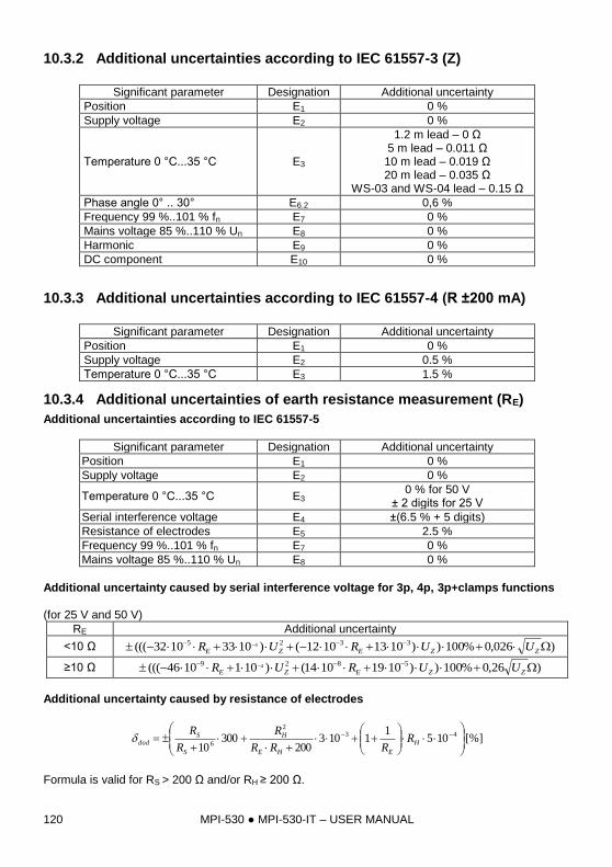
MPI-530 MPI-530-IT – USER MANUAL 120
10.3.2 Additional uncertainties according to IEC 61557-3 (Z)
Significant parameter Designation Additional uncertainty
Position E1 0 %
Supply voltage E2 0 %
Temperature 0 °C...35 °C E3
1.2 m lead – 0 Ω 5 m lead – 0.011 Ω
10 m lead – 0.019 Ω 20 m lead – 0.035 Ω
WS-03 and WS-04 lead – 0.15 Ω
Phase angle 0° .. 30° E6.2 0,6 %
Frequency 99 %..101 % fn E7 0 %
Mains voltage 85 %..110 % Un E8 0 %
Harmonic E9 0 %
DC component E10 0 %
10.3.3 Additional uncertainties according to IEC 61557-4 (R ±200 mA)
Significant parameter Designation Additional uncertainty
Position E1 0 %
Supply voltage E2 0.5 %
Temperature 0 °C...35 °C E3 1.5 %
10.3.4 Additional uncertainties of earth resistance measurement (RE)
Additional uncertainties according to IEC 61557-5
Significant parameter Designation Additional uncertainty
Position E1 0 %
Supply voltage E2 0 %
Temperature 0 °C...35 °C E3 0 % for 50 V
± 2 digits for 25 V
Serial interference voltage E4 ±(6.5 % + 5 digits)
Resistance of electrodes E5 2.5 %
Frequency 99 %..101 % fn E7 0 %
Mains voltage 85 %..110 % Un E8 0 %
Additional uncertainty caused by serial interference voltage for 3p, 4p, 3p+clamps functions (for 25 V and 50 V)
RE Additional uncertainty
<10 Ω )026,0%100))10131012()10331032((( 3325 4
ZZEZE UURUR
≥10 Ω )26,0%100))10191014()1011046((( 5829 4
ZZEZE UURUR
Additional uncertainty caused by resistance of electrodes
[%]1051
1103200
30010
432
6
H
EHE
H
S
Sdod R
RRR
R
R
R
Formula is valid for RS > 200 Ω and/or RH ≥ 200 Ω.
Rh/Re =
20000
Rh/Re =
10000
Rh/Re =
Rh/Re =
2000
Rh/Re =
5000
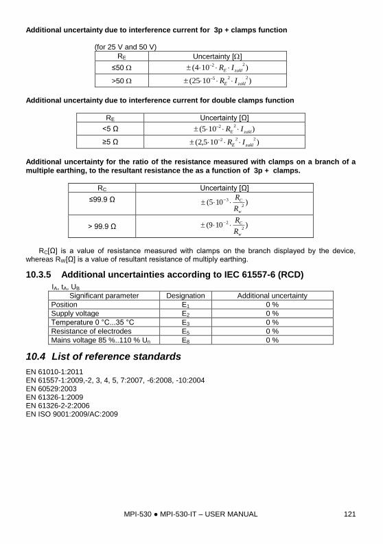
MPI-530 MPI-530-IT – USER MANUAL 121
Additional uncertainty due to interference current for 3p + clamps function (for 25 V and 50 V)
RE Uncertainty []
≤50 )104(22
zaklE IR
>50 )1025(225
zaklE IR
Additional uncertainty due to interference current for double clamps function
RE Uncertainty [Ω]
<5 Ω )105(22
zaklE IR
≥5 Ω )105,2(222
zaklE IR
Additional uncertainty for the ratio of the resistance measured with clamps on a branch of a
multiple earthing, to the resultant resistance the as a function of 3p + clamps.
RC Uncertainty [Ω]
≤99.9 Ω
)105(2
3
w
C
R
R
> 99.9 Ω )109(2
2
w
C
R
R
RC[Ω] is a value of resistance measured with clamps on the branch displayed by the device,
whereas RW[Ω] is a value of resultant resistance of multiply earthing.
10.3.5 Additional uncertainties according to IEC 61557-6 (RCD)
IA, tA, UB
Significant parameter Designation Additional uncertainty
Position E1 0 %
Supply voltage E2 0 %
Temperature 0 °C...35 °C E3 0 %
Resistance of electrodes E5 0 %
Mains voltage 85 %..110 % Un E8 0 %
10.4 List of reference standards
EN 61010-1:2011 EN 61557-1:2009,-2, 3, 4, 5, 7:2007, -6:2008, -10:2004 EN 60529:2003 EN 61326-1:2009 EN 61326-2-2:2006 EN ISO 9001:2009/AC:2009
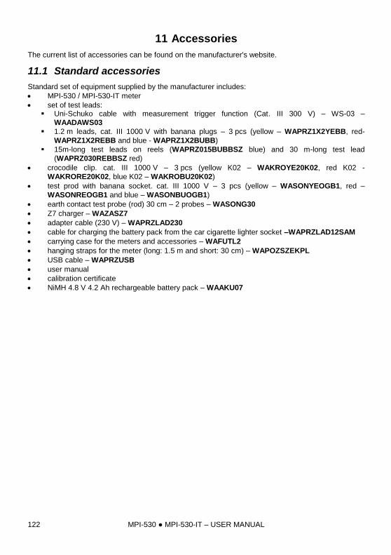
MPI-530 MPI-530-IT – USER MANUAL 122
11 Accessories
The current list of accessories can be found on the manufacturer's website.
11.1 Standard accessories
Standard set of equipment supplied by the manufacturer includes:
MPI-530 / MPI-530-IT meter
set of test leads: Uni-Schuko cable with measurement trigger function (Cat. III 300 V) – WS-03 –
WAADAWS03
1.2 m leads, cat. III 1000 V with banana plugs – 3 pcs (yellow – WAPRZ1X2YEBB, red-
WAPRZ1X2REBB and blue - WAPRZ1X2BUBB)
15m-long test leads on reels (WAPRZ015BUBBSZ blue) and 30 m-long test lead
(WAPRZ030REBBSZ red)
crocodile clip. cat. III 1000 V – 3 pcs (yellow K02 – WAKROYE20K02, red K02 -
WAKRORE20K02, blue K02 – WAKROBU20K02)
test prod with banana socket. cat. III 1000 V – 3 pcs (yellow – WASONYEOGB1, red –
WASONREOGB1 and blue – WASONBUOGB1)
earth contact test probe (rod) 30 cm – 2 probes – WASONG30
Z7 charger – WAZASZ7
adapter cable (230 V) – WAPRZLAD230
cable for charging the battery pack from the car cigarette lighter socket –WAPRZLAD12SAM
carrying case for the meters and accessories – WAFUTL2
hanging straps for the meter (long: 1.5 m and short: 30 cm) – WAPOZSZEKPL
USB cable – WAPRZUSB
user manual
calibration certificate
NiMH 4.8 V 4.2 Ah rechargeable battery pack – WAAKU07
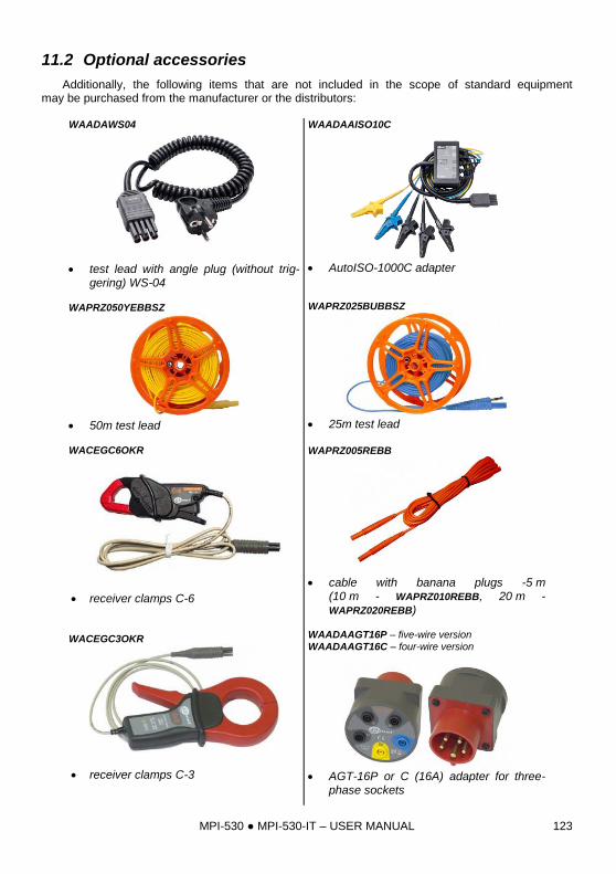
MPI-530 MPI-530-IT – USER MANUAL 123
11.2 Optional accessories
Additionally, the following items that are not included in the scope of standard equipment may be purchased from the manufacturer or the distributors:
WAADAWS04
test lead with angle plug (without trig-gering) WS-04
WAPRZ050YEBBSZ
50m test lead WACEGC6OKR
receiver clamps C-6 WACEGC3OKR
receiver clamps C-3
WAADAAISO10C
AutoISO-1000C adapter
WAPRZ025BUBBSZ
25m test lead WAPRZ005REBB
cable with banana plugs -5 m (10 m - WAPRZ010REBB, 20 m - WAPRZ020REBB)
WAADAAGT16P – five-wire version WAADAAGT16C – four-wire version
AGT-16P or C (16A) adapter for three-
phase sockets
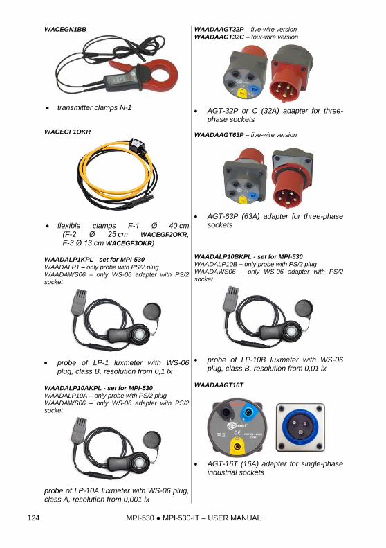
MPI-530 MPI-530-IT – USER MANUAL 124
WACEGN1BB
transmitter clamps N-1 WACEGF1OKR
flexible clamps F-1 Ø 40 cm (F-2 Ø 25 cm WACEGF2OKR, F-3 Ø 13 cm WACEGF3OKR)
WAADALP1KPL - set for MPI-530 WAADALP1 – only probe with PS/2 plug WAADAWS06 – only WS-06 adapter with PS/2 socket
probe of LP-1 luxmeter with WS-06
plug, class B, resolution from 0,1 lx WAADALP10AKPL - set for MPI-530 WAADALP10A – only probe with PS/2 plug WAADAWS06 – only WS-06 adapter with PS/2 socket
probe of LP-10A luxmeter with WS-06 plug, class A, resolution from 0,001 lx
WAADAAGT32P – five-wire version
WAADAAGT32C – four-wire version
AGT-32P or C (32A) adapter for three-
phase sockets WAADAAGT63P – five-wire version
AGT-63P (63A) adapter for three-phase
sockets
WAADALP10BKPL - set for MPI-530 WAADALP10B – only probe with PS/2 plug WAADAWS06 – only WS-06 adapter with PS/2 socket
probe of LP-10B luxmeter with WS-06
plug, class B, resolution from 0,01 lx WAADAAGT16T
AGT-16T (16A) adapter for single-phase
industrial sockets
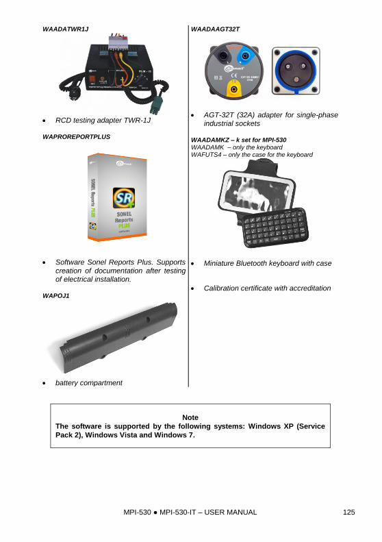
MPI-530 MPI-530-IT – USER MANUAL 125
WAADATWR1J
RCD testing adapter TWR-1J WAPROREPORTPLUS
Software Sonel Reports Plus. Supports creation of documentation after testing of electrical installation.
WAPOJ1
battery compartment
WAADAAGT32T
AGT-32T (32A) adapter for single-phase industrial sockets
WAADAMKZ – k set for MPI-530 WAADAMK – only the keyboard WAFUTS4 – only the case for the keyboard
Miniature Bluetooth keyboard with case
Calibration certificate with accreditation
Note
The software is supported by the following systems: Windows XP (Service
Pack 2), Windows Vista and Windows 7.
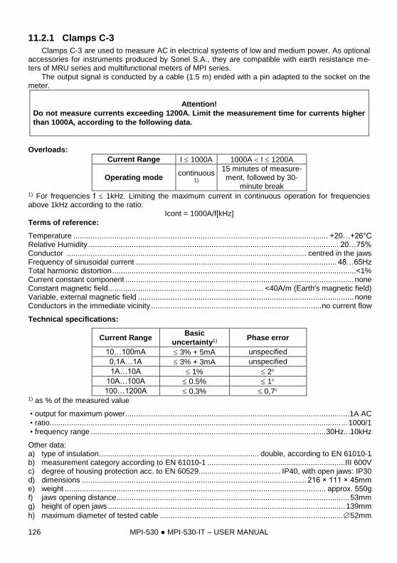
MPI-530 MPI-530-IT – USER MANUAL 126
11.2.1 Clamps C-3
Clamps C-3 are used to measure AC in electrical systems of low and medium power. As optional accessories for instruments produced by Sonel S.A., they are compatible with earth resistance me-ters of MRU series and multifunctional meters of MPI series. The output signal is conducted by a cable (1.5 m) ended with a pin adapted to the socket on the meter.
Attention!
Do not measure currents exceeding 1200A. Limit the measurement time for currents higher
than 1000A, according to the following data.
Overloads:
Current Range I 1000A 1000A I 1200A
Operating mode continuous
1)
15 minutes of measure-ment, followed by 30-
minute break 1) For frequencies f 1kHz. Limiting the maximum current in continuous operation for frequencies above 1kHz according to the ratio:
Icont = 1000A/f[kHz]
Terms of reference:
Temperature ...................................................................................................................... +20…+26°C Relative Humidity .................................................................................................................... 20…75% Conductor ............................................................................................................... centred in the jaws Frequency of sinusoidal current ............................................................................................. 48…65Hz Total harmonic distortion ................................................................................................................. <1% Current constant component .......................................................................................................... none Constant magnetic field........................................................................ <40A/m (Earth's magnetic field) Variable, external magnetic field .................................................................................................... none Conductors in the immediate vicinity ............................................................................... no current flow
Technical specifications:
Current Range Basic
uncertainty1) Phase error
10…100mA 3% + 5mA unspecified
0,1A…1A 3% + 3mA unspecified
1A…10A 1% 2
10A…100A 0.5% 1
100…1200A 0.3% 0,7 1) as % of the measured value
• output for maximum power ........................................................................................................1A AC
• ratio.......................................................................................................................................... 1000/1
• frequency range ............................................................................................................. 30Hz...10kHz
Other data: a) type of insulation .......................................................................... double, according to EN 61010-1 b) measurement category according to EN 61010-1 ................................................................III 600V c) degree of housing protection acc. to EN 60529...................................... IP40, with open jaws: IP30 d) dimensions ........................................................................................................ 216 × 111 × 45mm e) weight ......................................................................................................................... approx. 550g f) jaws opening distance ............................................................................................................ 53mm g) height of open jaws .............................................................................................................. 139mm
h) maximum diameter of tested cable ..................................................................................... 52mm
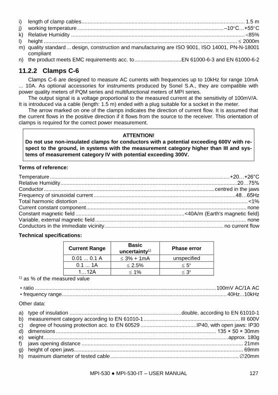
MPI-530 MPI-530-IT – USER MANUAL 127
i) length of clamp cables ............................................................................................................ 1.5 m
j) working temperature ................................................................................................. –10C…+55C
k) Relative Humidity ................................................................................................................... 85%
l) height ................................................................................................................................ 2000m m) quality standard ... design, construction and manufacturing are ISO 9001, ISO 14001, PN-N-18001
compliant n) the product meets EMC requirements acc. to ............................... EN 61000-6-3 and EN 61000-6-2
11.2.2 Clamps C-6
Clamps C-6 are designed to measure AC currents with frequencies up to 10kHz for range 10mA ... 10A. As optional accessories for instruments produced by Sonel S.A., they are compatible with power quality meters of PQM series and multifunctional meters of MPI series. The output signal is a voltage proportional to the measured current at the sensitivity of 100mV/A. It is introduced via a cable (length: 1.5 m) ended with a plug suitable for a socket in the meter. The arrow marked on one of the clamps indicates the direction of current flow. It is assumed that the current flows in the positive direction if it flows from the source to the receiver. This orientation of clamps is required for the correct power measurement.
ATTENTION!
Do not use non-insulated clamps for conductors with a potential exceeding 600V with re-
spect to the ground, in systems with the measurement category higher than III and sys-
tems of measurement category IV with potential exceeding 300V.
Terms of reference:
Temperature ....................................................................................................................... +20…+26°C Relative Humidity ..................................................................................................................... 20…75% Conductor ................................................................................................................. centred in the jaws Frequency of sinusoidal current ..............................................................................................48…65Hz Total harmonic distortion ................................................................................................................ <1% Current constant component .......................................................................................................... none Constant magnetic field ........................................................................ <40A/m (Earth's magnetic field) Variable, external magnetic field .................................................................................................... none Conductors in the immediate vicinity............................................................................... no current flow
Technical specifications:
Current Range Basic
uncertainty1) Phase error
0.01 ... 0.1 A 3% + 1mA unspecified
0.1 ... 1A 2.5% 5
1…12A 1% 3 1) as % of the measured value
• ratio ........................................................................................................................ 100mV AC/1A AC
• frequency range ............................................................................................................. 40Hz...10kHz
Other data:
a) type of insulation .......................................................................... double, according to EN 61010-1 b) measurement category according to EN 61010-1 ................................................................ III 600V c) degree of housing protection acc. to EN 60529 ..................................... IP40, with open jaws: IP30 d) dimensions .......................................................................................................... 135 × 50 × 30mm e) weight .......................................................................................................................... approx. 180g f) jaws opening distance ........................................................................................................... 21mm g) height of open jaws ................................................................................................................ 69mm
h) maximum diameter of tested cable ..................................................................................... 20mm
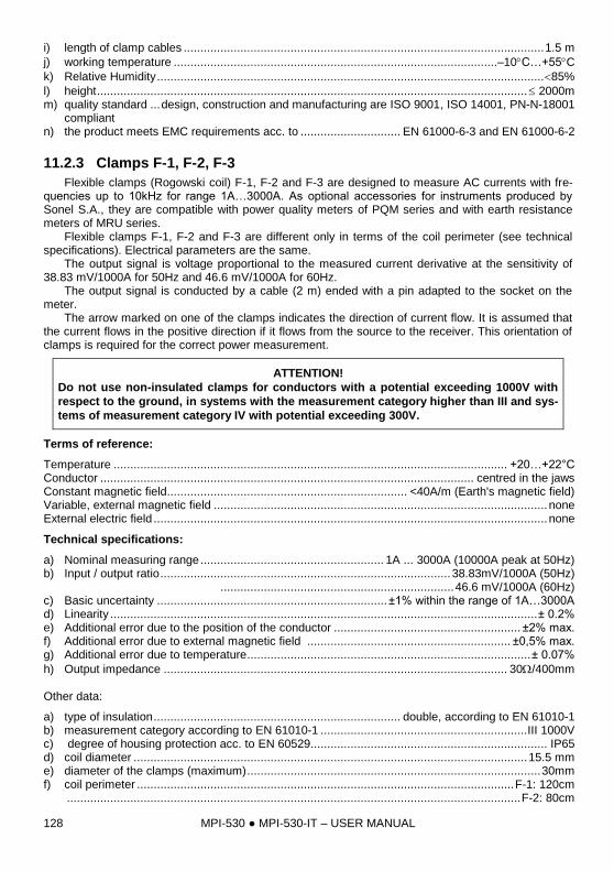
MPI-530 MPI-530-IT – USER MANUAL 128
i) length of clamp cables ............................................................................................................ 1.5 m
j) working temperature .................................................................................................–10C…+55C
k) Relative Humidity .................................................................................................................... 85%
l) height ................................................................................................................................. 2000m m) quality standard ... design, construction and manufacturing are ISO 9001, ISO 14001, PN-N-18001
compliant n) the product meets EMC requirements acc. to .............................. EN 61000-6-3 and EN 61000-6-2
11.2.3 Clamps F-1, F-2, F-3
Flexible clamps (Rogowski coil) F-1, F-2 and F-3 are designed to measure AC currents with fre-quencies up to 10kHz for range 1A…3000A. As optional accessories for instruments produced by Sonel S.A., they are compatible with power quality meters of PQM series and with earth resistance meters of MRU series. Flexible clamps F-1, F-2 and F-3 are different only in terms of the coil perimeter (see technical specifications). Electrical parameters are the same. The output signal is voltage proportional to the measured current derivative at the sensitivity of 38.83 mV/1000A for 50Hz and 46.6 mV/1000A for 60Hz. The output signal is conducted by a cable (2 m) ended with a pin adapted to the socket on the meter. The arrow marked on one of the clamps indicates the direction of current flow. It is assumed that the current flows in the positive direction if it flows from the source to the receiver. This orientation of clamps is required for the correct power measurement.
ATTENTION!
Do not use non-insulated clamps for conductors with a potential exceeding 1000V with
respect to the ground, in systems with the measurement category higher than III and sys-
tems of measurement category IV with potential exceeding 300V.
Terms of reference:
Temperature ...................................................................................................................... +20…+22°C Conductor ................................................................................................................ centred in the jaws Constant magnetic field........................................................................ <40A/m (Earth's magnetic field) Variable, external magnetic field .................................................................................................... none External electric field ...................................................................................................................... none
Technical specifications:
a) Nominal measuring range ....................................................... 1A ... 3000A (10000A peak at 50Hz) b) Input / output ratio ....................................................................................... 38.83mV/1000A (50Hz)
...................................................................... 46.6 mV/1000A (60Hz) c) Basic uncertainty ..................................................................... ±1% within the range of 1A…3000A d) Linearity ................................................................................................................................ ± 0.2% e) Additional error due to the position of the conductor ........................................................ ±2% max. f) Additional error due to external magnetic field ............................................................. ±0,5% max. g) Additional error due to temperature ..................................................................................... ± 0.07%
h) Output impedance ....................................................................................................... 30/400mm
Other data:
a) type of insulation .......................................................................... double, according to EN 61010-1 b) measurement category according to EN 61010-1 .............................................................. III 1000V c) degree of housing protection acc. to EN 60529....................................................................... IP65 d) coil diameter ...................................................................................................................... 15.5 mm e) diameter of the clamps (maximum) ........................................................................................ 30mm f) coil perimeter ................................................................................................................. F-1: 120cm
........................................................................................................................................ F-2: 80cm
MPI-530 MPI-530-IT – USER MANUAL 129
........................................................................................................................................ F-3: 45cm g) inner diameter of clamps after closing .......................................................................... F-1: 360mm
..................................................................................................................................... F-2: 235mm ..................................................................................................................................... F-3: 120mm
h) weight .................................................................................................................. F-1: approx. 410g ............................................................................................................................ F-2: approx. 310g ............................................................................................................................ F-3: approx. 220g
i) length of clamp cables ................................................................................................................ 2m
j) working temperature ................................................................................................. –20C…+80C k) quality standard ... design, construction and manufacturing are ISO 9001, ISO 14001, PN-N-18001
compliant l) the product meets EMC requirements acc. to ............................... EN 61000-6-3 and EN 61000-6-2
11.2.4 Clamps N-1
Clamps N-1, as optional accessories for instruments produced by Sonel S.A., are compatible with earth resistance meters of MRU series and are designed to be signal transmitting clamps in double-clamp measurements. The output signal is transmitted via two banana plugs.
Overloads:
Current Range I 1000A 1000A I 1200A
Operating mode continuous
1
15 minutes of measure-ment, followed by 30-
minute break 1) For frequencies f 1kHz. Limiting the maximum current in continuous operation for frequencies above 1kHz according to the ratio:
Icont = 1000A/f[kHz]
Terms of reference: Temperature ....................................................................................................................... +20…+26°C Relative Humidity ..................................................................................................................... 20…75% Conductor ................................................................................................................. centred in the jaws Current constant component .......................................................................................................... none Constant magnetic field ........................................................................ <40A/m (Earth's magnetic field) Variable, external magnetic field .................................................................................................... none Conductors in the immediate vicinity............................................................................... no current flow
Technical specifications:
a) output for maximum power .................................................................................................... 1A AC b) ratio ...................................................................................................................................... 1000/1 c) frequency range.......................................................................................................... 30Hz...10kHz d) type of insulation .......................................................................... double, according to EN 61010-1 e) measurement category according to EN 61010-1 ................................................................ III 600V f) degree of housing protection acc. to EN 60529 ..................................... IP40, with open jaws: IP30 g) dimensions ........................................................................................................ 216 × 111 × 45mm h) weight .......................................................................................................................... approx. 550g i) jaws opening distance ........................................................................................................... 53mm j) height of open jaws .............................................................................................................. 139mm
k) maximum diameter of tested cable ..................................................................................... 52mm
l) working temperature ................................................................................................. –10C…+55C
m) Relative Humidity ................................................................................................................... 85%
n) height ................................................................................................................................ 2000m o) quality standard ... design, construction and manufacturing are ISO 9001, ISO 14001, PN-N-18001
compliant p) the product meets EMC requirements acc. to ............................... EN 61000-6-3 and EN 61000-6-2
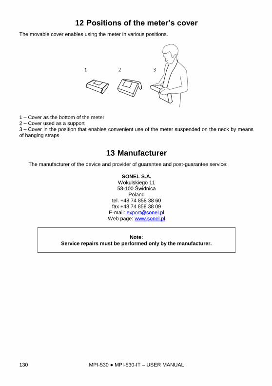
MPI-530 MPI-530-IT – USER MANUAL 130
12 Positions of the meter’s cover
The movable cover enables using the meter in various positions.
1 2 3
1 – Cover as the bottom of the meter 2 – Cover used as a support 3 – Cover in the position that enables convenient use of the meter suspended on the neck by means of hanging straps
13 Manufacturer
The manufacturer of the device and provider of guarantee and post-guarantee service:
SONEL S.A. Wokulskiego 11 58-100 Świdnica
Poland tel. +48 74 858 38 60 fax +48 74 858 38 09
E-mail: [email protected] Web page: www.sonel.pl
Note:
Service repairs must be performed only by the manufacturer.

MPI-530 MPI-530-IT – USER MANUAL 131
14 Laboratory services
SONEL Testing and Calibration Laboratory has been accredited by the Polish Center for Accreditation (PCA) - certificate no. AP 173. Laboratory offers calibration for the following instruments that are used for measuring electrical and non-electrical parameters.
METERS FOR MEASUREMENTS OF ELECTRICAL PARAMETERS
o voltage meters,
o current meters (including clamp meters),
o resistance meters,
o insulation resistance meters,
o earth resistance and resistivity meters,
o RCD meters,
o short-circuit loop impedance meters,
o power quality analyzers,
o portable appliance testers (PAT),
o power meters,
o multimeters,
o multifunction meters covering the functions of the above-mentioned instruments,
ELECTRICAL STANDARDS
o calibrators,
o resistance standards,
METERS FOR MEASUREMENTS OF NON-ELECTRICAL PARAMETERS
o pyrometers,
o thermal imagers,
o luxmeters.
The Calibration Certificate is a document that presents a relation between the calibration standard of known accuracy and meter indications with associated measurement uncertainties. The calibration standards are normally traceable to the national standard held by the National Metrological Institute. According to ILAC-G24 „Guidelines for determination of calibration intervals of measuring instru-ments”, SONEL S.A. recommends periodical metrological inspection of the instruments it manufac-tures no less frequently than once every 12 months. For new instruments provided with the Calibration Certificate or Validation Certificate at the factory, re-calibration should be performed within 12 months from the date of purchase, however, no later than 24 months from the date of purchase.
ATTENTION !
The person performing the measurements should be absolutely sure about the efficiency of
the device being used. Measurements made with an inefficient meter can contribute to an in-
correct assessment of the effectiveness of health protection and even human life.

MPI-530 MPI-530-IT – USER MANUAL 132
NOTES