mpeg-4 for interactive low-delay real-time communication
TRANSCRIPT

MPEG-4 for Interactive Low-delay Real-time Communication
Olaf Landsiedel and Gary Minden
ITTC-FY2004-TR-23150-10
December 2003
Copyright © 2003:The University of Kansas2335 Irving Hill Road, Lawrence, KS 66045-7612All rights reserved.
Technical Report
The University of Kansas
ii
Abstract Internet broadcasting techniques are wide spread and have been the focus off many research projects. Due to high transmission delays these systems often lack interactivity.
This thesis introduces a new streaming system to deliver real-time video and audio data with low-delays across the Internet. Packet loss, jitter and changing bandwidth availability describe the challenges that have to be handled by the system, since the Internet is a best effort network and does not guarantee quality of service.
To lower bit-rates audio and video data are usually compressed in formats like MPEG-4. The high compression nearly eliminates redundancy in the audio and video data. A resultant loss of transmitted data and transmission errors can have big impact on the quality of the received stream. MPEG-4 video uses inter frame prediction, so errors propagate between frames. We will argue that retransmission of lost or invalid data is not feasible for low-delay communication due to high control loop delays.
The changing conditions of the internet make adaptation to the available bandwidth necessary. The traditional approach of buffering data to smoothen bandwidth oscillations is not usable due to the real-time constraints of the interactive communication. In addition TCP like congestion control cannot be applied, because it results in extreme transmission rate oscillations.
We introduce and evaluate two techniques - adaptive key frame addition and binominal congestion control for RTP - to reduce the impact of the changing conditions and lost frames. A MPEG-4 low-delay real-time streaming system for low bit-rates is implemented to incorporate and evaluate the new techniques.

iii
Acknowledgements
I want to thank many people for making my time in the US here at the University of
Kansas possible and for the chance to do my research at the Information and
Technology Center ITTC.
• Prof. Dr. Minden for being my academic advisor and allowing me to be a
member of his research team. Prof. Minden allowed me to go my own ways
for my research and his technical knowledge made working with him a
privilege.
• My Committee for taking the time to read and grade my work.
• Leon Searl for his advice and help with all big and small problems I
encountered during my work. Leon was always patient with any questions I
asked him, it was a pleasure to work with him.
• The same I have to say about my lab- and team-mate James Mauro. He was
always willing to answer all kinds of questions. James also helped me with the
integration of my research into the ACE framework.
• The Department of State, Fulbright and IIE for the Fulbright Travel Grant.
• The “Christian Albrechts Universität zu Kiel“, Germany, and the “University
of Kansas”, Kansas, for providing me twice with a “Direct Exchange
Scholarship”. Without this grant, my studies in the US would not have been
possible in the way they were.
• DARPA, NSF, Sprint and the University of Kansas for funding ACE.
iv
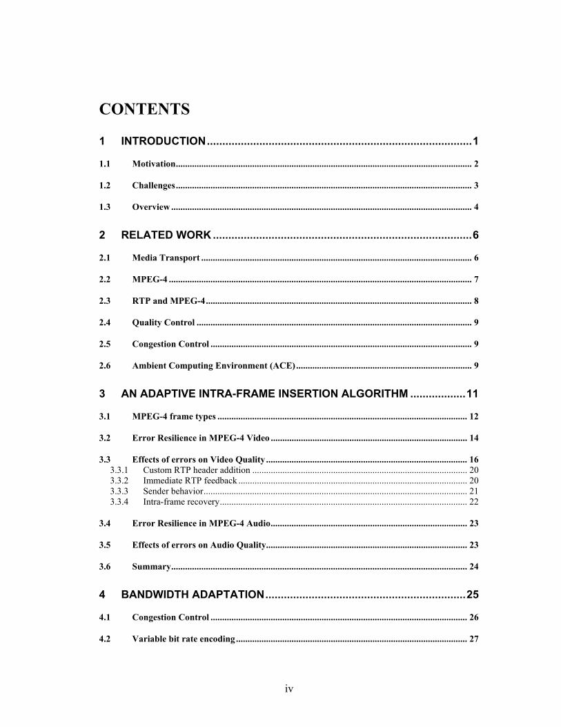
CONTENTS
1 INTRODUCTION......................................................................................1
1.1 Motivation................................................................................................................................ 2
1.2 Challenges................................................................................................................................ 3
1.3 Overview .................................................................................................................................. 4
2 RELATED WORK ....................................................................................6
2.1 Media Transport ..................................................................................................................... 6
2.2 MPEG-4 ................................................................................................................................... 7
2.3 RTP and MPEG-4................................................................................................................... 8
2.4 Quality Control ....................................................................................................................... 9
2.5 Congestion Control ................................................................................................................. 9
2.6 Ambient Computing Environment (ACE)............................................................................ 9
3 AN ADAPTIVE INTRA-FRAME INSERTION ALGORITHM ..................11
3.1 MPEG-4 frame types ............................................................................................................ 12
3.2 Error Resilience in MPEG-4 Video ..................................................................................... 14
3.3 Effects of errors on Video Quality ....................................................................................... 16 3.3.1 Custom RTP header addition ............................................................................................. 20 3.3.2 Immediate RTP feedback ................................................................................................... 20 3.3.3 Sender behavior.................................................................................................................. 21 3.3.4 Intra-frame recovery........................................................................................................... 22
3.4 Error Resilience in MPEG-4 Audio..................................................................................... 23
3.5 Effects of errors on Audio Quality....................................................................................... 23
3.6 Summary................................................................................................................................ 24
4 BANDWIDTH ADAPTATION.................................................................25
4.1 Congestion Control ............................................................................................................... 26
4.2 Variable bit rate encoding .................................................................................................... 27
v
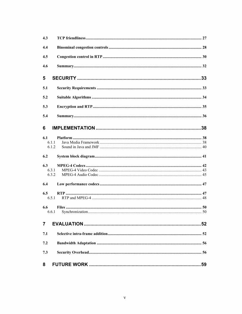
4.3 TCP friendliness.................................................................................................................... 27
4.4 Binominal congestion controls ............................................................................................. 28
4.5 Congestion control in RTP ................................................................................................... 30
4.6 Summary................................................................................................................................ 32
5 SECURITY .............................................................................................33
5.1 Security Requirements ......................................................................................................... 33
5.2 Suitable Algorithms .............................................................................................................. 34
5.3 Encryption and RTP............................................................................................................. 35
5.4 Summary................................................................................................................................ 36
6 IMPLEMENTATION ...............................................................................38
6.1 Platform ................................................................................................................................. 38 6.1.1 Java Media Framework ...................................................................................................... 38 6.1.2 Sound in Java and JMF ...................................................................................................... 40
6.2 System block diagram........................................................................................................... 41
6.3 MPEG-4 Codecs .................................................................................................................... 42 6.3.1 MPEG-4 Video Codec ....................................................................................................... 43 6.3.2 MPEG-4 Audio Codec ....................................................................................................... 45
6.4 Low performance codecs ...................................................................................................... 47
6.5 RTP ........................................................................................................................................ 47 6.5.1 RTP and MPEG-4 .............................................................................................................. 48
6.6 Files ........................................................................................................................................ 50 6.6.1 Synchronization.................................................................................................................. 50
7 EVALUATION........................................................................................52
7.1 Selective intra-frame addition.............................................................................................. 52
7.2 Bandwidth Adaptation ......................................................................................................... 56
7.3 Security Overhead................................................................................................................. 56
8 FUTURE WORK ....................................................................................59
vi
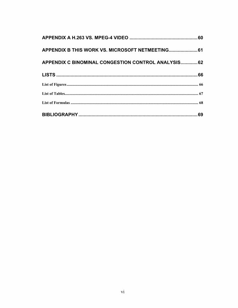
APPENDIX A H.263 VS. MPEG-4 VIDEO ....................................................60
APPENDIX B THIS WORK VS. MICROSOFT NETMEETING......................61
APPENDIX C BINOMINAL CONGESTION CONTROL ANALYSIS.............62
LISTS ............................................................................................................66
List of Figures ...................................................................................................................................... 66
List of Tables........................................................................................................................................ 67
List of Formulas .................................................................................................................................. 68
BIBLIOGRAPHY...........................................................................................69
1
1 Introduction
Internet broadcasting techniques are wide spread and have been the focus off many
research projects. Due to high transmission and coding delays these systems often
lack interactivity. In addition security, bandwidth adaptation and transmission error
recovery are not fully addressed in most of today’s systems.
This thesis introduces a new streaming system to deliver real-time video and audio
data with low-delays across the Internet suitable for interactive conversation. Packet
loss, jitter and changing bandwidth availability describe the challenges that have to be
handled by the system, since the Internet is a best effort network and does not
guarantee quality of service. Furthermore security, error recovery, bandwidth
adaptation and high compression are needed, to deploy a full functional system.
We introduce and evaluate two techniques - adaptive key frame addition and
binominal congestion control for RTP - to reduce the impact of the changing
conditions. A MPEG-4 low-delay real-time streaming system for low bit-rates was
implemented to incorporate and evaluate the introduced techniques.

2
1.1 Motivation
Many applications can benefit from high interactive streaming:
• Video Conferencing
• E-learning
• Remote control, example: robot control via an on-board camera or supervising
laboratory experiments
For them interactivity is essential, but most of today’s systems only allow limited
interactivity due to high transmission delays. Moreover most systems incorporate no
secure transmission and use low compression coding, resulting in blocky and staccato
video. The consequence is a reduced acceptance by users, although a more interactive
version of these applications would offer high benefits to them. To achieve a high
acceptance of video conferencing and e-learning by the community, these three key
issues have to be solved:
• Bandwidth:
The bandwidth today’s systems require is high and so their use is limited.
• Delay:
The transmission delay is too high to allow satisfying interactivity
• Security:
Today’s systems to do not incorporate secure transmissions
This thesis evaluates possible approaches to accomplish more interactivity while
reducing the required bandwidth and incorporating secure sessions. New coding

3
techniques allow higher compression of audio and video data, thereby reducing the
required bandwidth. We introduce a system that - in interaction with these coding
techniques - increases the interactivity and ensures privacy.
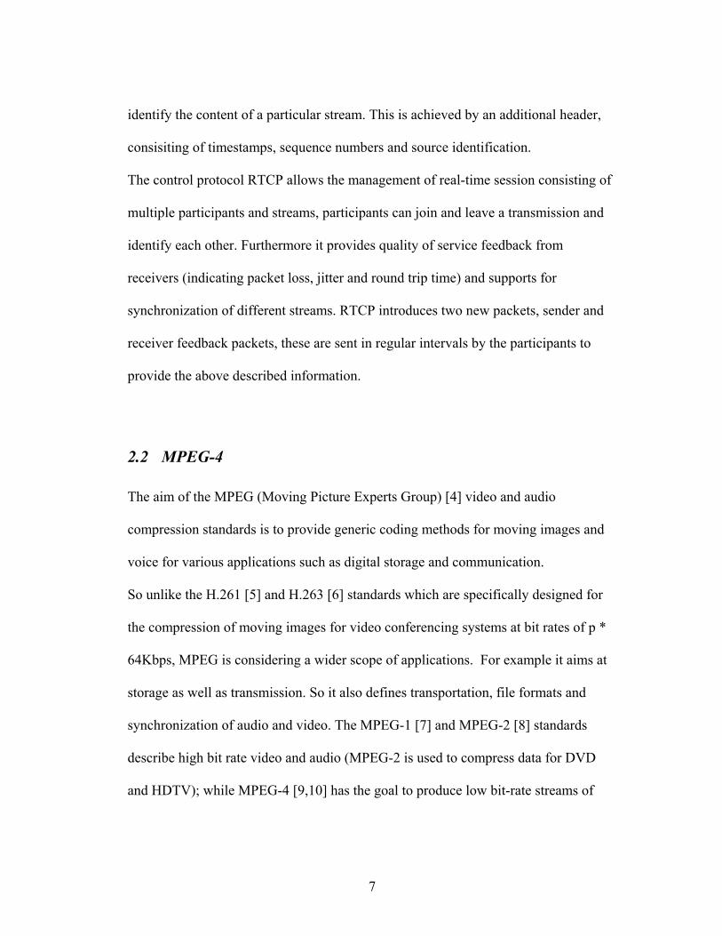
Figure 1-1 Basic block diagram of a video conference system
1.2 Challenges
User studies [1] indicate that users consider delays larger than 300ms not suitable for
interactive conversation. Since the Internet is a best-effort network and does not
guarantee quality of service, several problems have to be solved before low delay
streaming, suitable for interactive communication, via the Internet can be widely
deployed:
• Bandwidth variation:
Available bandwidth varies with time, the stream has to be adjusted to these
changing conditions to prevent packet loss.
Capture / Playback
encoding
Transmission
decoding
Playback / Capture
decoding encoding
4
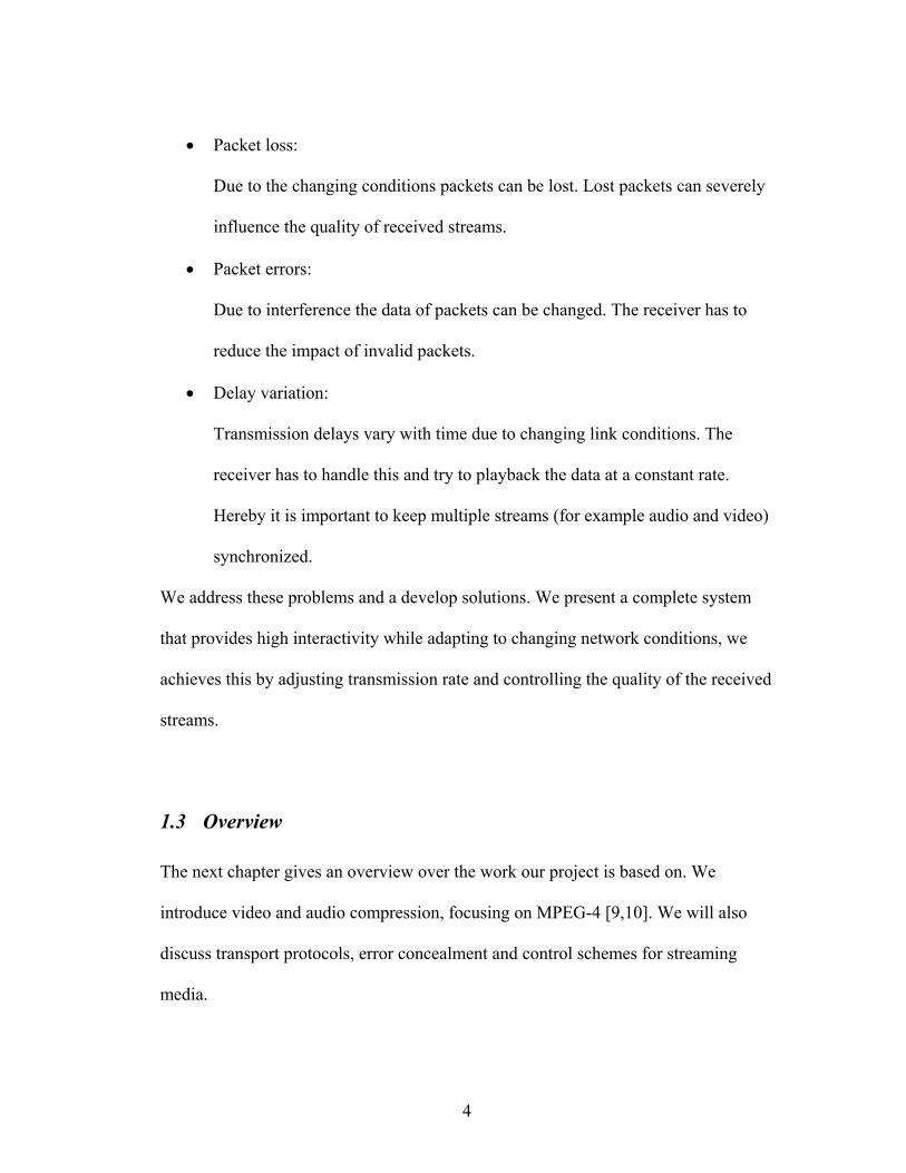
• Packet loss:
Due to the changing conditions packets can be lost. Lost packets can severely
influence the quality of received streams.
• Packet errors:
Due to interference the data of packets can be changed. The receiver has to
reduce the impact of invalid packets.
• Delay variation:
Transmission delays vary with time due to changing link conditions. The
receiver has to handle this and try to playback the data at a constant rate.
Hereby it is important to keep multiple streams (for example audio and video)
synchronized.
We address these problems and a develop solutions. We present a complete system
that provides high interactivity while adapting to changing network conditions, we
achieves this by adjusting transmission rate and controlling the quality of the received
streams.
1.3 Overview
The next chapter gives an overview over the work our project is based on. We
introduce video and audio compression, focusing on MPEG-4 [9,10]. We will also
discuss transport protocols, error concealment and control schemes for streaming
media.
5
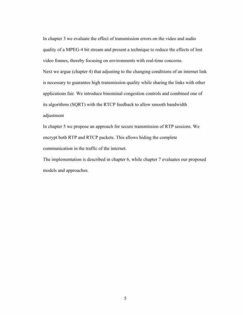
In chapter 3 we evaluate the effect of transmission errors on the video and audio
quality of a MPEG-4 bit stream and present a technique to reduce the effects of lost
video frames, thereby focusing on environments with real-time concerns.
Next we argue (chapter 4) that adjusting to the changing conditions of an internet link
is necessary to guarantee high transmission quality while sharing the links with other
applications fair. We introduce binominal congestion controls and combined one of
its algorithms (SQRT) with the RTCP feedback to allow smooth bandwidth
adjustment
In chapter 5 we propose an approach for secure transmission of RTP sessions. We
encrypt both RTP and RTCP packets. This allows hiding the complete
communication in the traffic of the internet.
The implementation is described in chapter 6, while chapter 7 evaluates our proposed
models and approaches.
6
2 Related Work
This chapter gives an overview over the work our project is based on. We introduce
video and audio compression, focusing on MPEG-4 [9,10]. We will also discuss
transport protocols, error concealment and control schemes for streaming media.
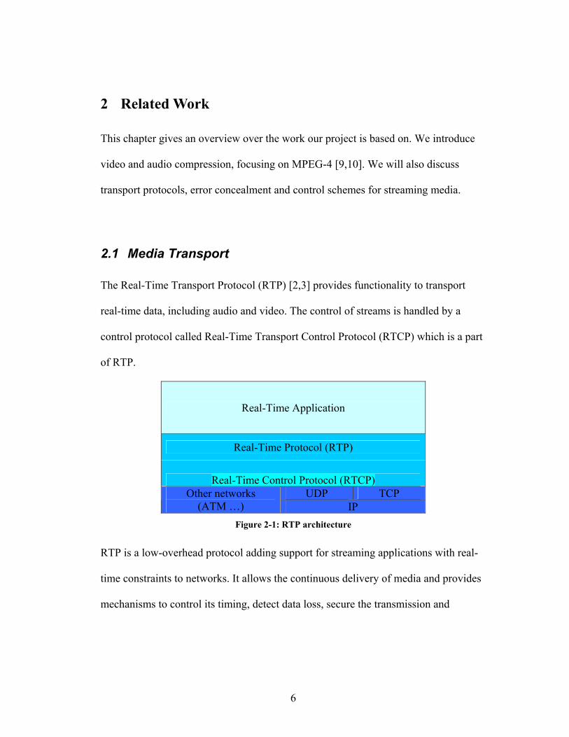
2.1 Media Transport
The Real-Time Transport Protocol (RTP) [2,3] provides functionality to transport
real-time data, including audio and video. The control of streams is handled by a
control protocol called Real-Time Transport Control Protocol (RTCP) which is a part
of RTP.
Real-Time Application
Real-Time Protocol (RTP)
Real-Time Control Protocol (RTCP) UDP TCP Other networks
(ATM …) IP Figure 2-1: RTP architecture
RTP is a low-overhead protocol adding support for streaming applications with real-
time constraints to networks. It allows the continuous delivery of media and provides
mechanisms to control its timing, detect data loss, secure the transmission and
7
identify the content of a particular stream. This is achieved by an additional header,
consisiting of timestamps, sequence numbers and source identification.
The control protocol RTCP allows the management of real-time session consisting of
multiple participants and streams, participants can join and leave a transmission and
identify each other. Furthermore it provides quality of service feedback from
receivers (indicating packet loss, jitter and round trip time) and supports for
synchronization of different streams. RTCP introduces two new packets, sender and
receiver feedback packets, these are sent in regular intervals by the participants to
provide the above described information.
2.2 MPEG-4
The aim of the MPEG (Moving Picture Experts Group) [4] video and audio
compression standards is to provide generic coding methods for moving images and
voice for various applications such as digital storage and communication.
So unlike the H.261 [5] and H.263 [6] standards which are specifically designed for
the compression of moving images for video conferencing systems at bit rates of p *
64Kbps, MPEG is considering a wider scope of applications. For example it aims at
storage as well as transmission. So it also defines transportation, file formats and
synchronization of audio and video. The MPEG-1 [7] and MPEG-2 [8] standards
describe high bit rate video and audio (MPEG-2 is used to compress data for DVD
and HDTV); while MPEG-4 [9,10] has the goal to produce low bit-rate streams of
8
audio and video data. Furthermore MPEG-4 has error resilience capabilities to reduce
the impact of a lost frame or bit errors caused by transport across a lossy connection.
A MPEG-4 video frame is coded as a Video Object Plane (VOP). For easier
understanding and without loss of accuracy or generality we will use the words frame
and VOP interchangeably.
MPEG-4 audio is called AAC (Advanced Audio Coding) [9,11]. MPEG-4 AAC is
based on MPEG-2 AAC with additions to improve error resilience and reduce coding
delay.
2.3 RTP and MPEG-4
RFC 3016 [12] describes the direct mapping of video and audio streams on RTP-
packets, while a RFC draft [13] introduces a new RTCP packet for immediate
feedback. We use it to utilize the resynchronization feature of MPEG-4 streams.
Usually a predictive frame bases its prediction on the previous frame; in addition
MPEG-4 allows basing the prediction on any frame. To signal this, a special
resynchronization marker is used.
The features described above make MPEG-4 an ideal candidate for streaming.
To support even higher compression, new layers [14,15] have been recently (late
2002) added to MPEG-4; they allow even lower bit rates without reducing quality and
are currently under heavy development.
9
2.4 Quality Control
Current research has focused on techniques for (selective) retransmission of corrupted
or lost data [16,17,18,19]. We will show (chapter 3) that retransmission cannot be
applied when high interactivity is needed.
Other research has been done on error concealment and resilience [20,21] of real-time
audio and video transmissions. MPEG-4 has build in error concealment features
[9,10,22], that limit the propagation of errors resulting from bit errors or lost frames.
2.5 Congestion Control
As congestion control is needed for TCP connections to use the bandwidth in an
optimal and fair way, it is needed for real-time streaming. Early research
[23,24,25,26,27] on multimedia congestion control proposed models similar to TCP.
They were like the TCP congestion control, just without reliability and in-order
delivery. Newer ones also focus on reducing the high oscillations of the transmission
rate caused by TCP congestion control schemes [28,29,30].
2.6 Ambient Computing Environment (ACE)
“The ACE project involves the design and implementation of an environment where
embedded resources are at our finger tips. Ambient Computational Environment
represents a computer architecture in which computational resources, sensors, and

10
actuators, in their widest sense, are available in our offices, conference rooms,
hallways, and other places. Users must be able to control, with authorization, these
computational resources within their proximate area, and access computational
services that are long-lived and extremely robust. These users must also be able to
interact in multiple ways with ACEs. We are developing prototype Ambient
Computational Environments with these features, and are exploring the related
architectural and deployment issues.” [31]
ACE has been developed here at the Information and Telecommunication Technology
Center (ITTC) [32] at the University of Kansas [33].
11
3 An adaptive intra-frame insertion algorithm
The loss of video packets during transmission has big impact on the bit-stream
quality, since the amount of redundant information in the encoded bit stream is
limited. Internet Protocols like TCP guarantee delivery. They allow recovery from
packet loss by packet retransmission, were retransmission requires buffering and so
increases the transmission delay. These protocols also use congestion control
algorithms to reduce the possibility of packet loss. A congestion control algorithm
reduces the transmission rate after the loss of a packet and probes for available
bandwidth by increasing the transmission rate, when a packet has been successfully
delivered.
RTP transmission is usually encapsulated in an UDP-protocol, which does not
guarantee the delivery of packets. However, RTP provides features to signal the loss
of a packet based on sequence numbers. Another problem is the validation of the
received packets. The UDP checksum can be used to signal the flipping of bits, but is
not useful for recovery.
Retransmission of lost or invalid packets is an appropriate solution [16,17,18,19] for
streaming applications that use long buffers. But for real-time streaming with the goal
of high interactivity (example video conferencing), the retransmission would add high
delays and is not useful. To allow high interactivity, the end-to-end delay should be
below 300ms. Since the communication is bidirectional, each direction should have
an average delay below 150ms. Assume an average 80ms network transmission
12
delay, the delay after retransmission would be 240ms. In addition the other direction
would add another 80ms delay, summing up to 320ms. Since also capture, encoding,
encryption and their counterparts on the receiver side cause delays (on fast systems
about 100ms); our average delay would be 120ms above the acceptable maximum.
Buffers to compensate for network transmission jitter further increase the delay; even
without retransmission the goal of high interactivity is a challenge. In this chapter we
evaluate a solution for this problem.
3.1 MPEG-4 frame types
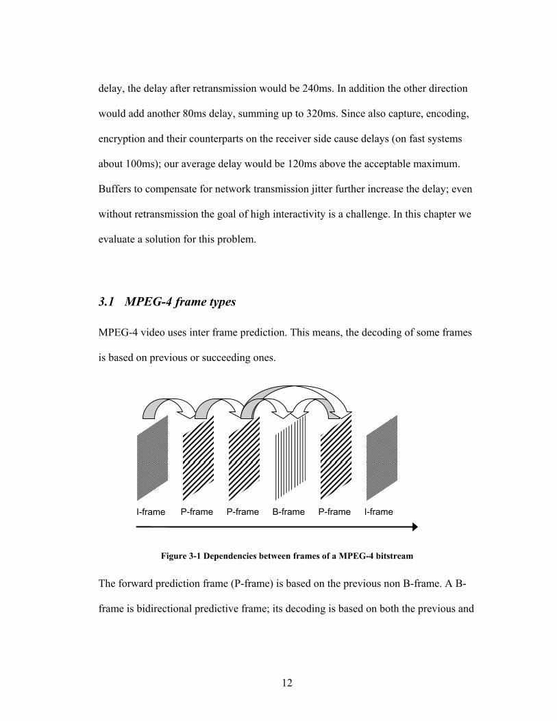
MPEG-4 video uses inter frame prediction. This means, the decoding of some frames
is based on previous or succeeding ones.
Figure 3-1 Dependencies between frames of a MPEG-4 bitstream
The forward prediction frame (P-frame) is based on the previous non B-frame. A B-
frame is bidirectional predictive frame; its decoding is based on both the previous and
I-frame I-frame P-frame P-frame B-frame P-frame I-frame

13
succeeding non B-frame. The intra-frame (I-frame) is used as reference frame and
does not depend on any previous or succeeding frame. Figure 3-1 shows these
dependencies. Since the encoding and decoding of B-frames depends on data of
succeeding frames, this frame type is not suitable for low-delay real-time
transmission.
In inter-frame prediction, as it is used in MPEG-4, errors caused by lost or corrupted
frames propagate between frames. Recovery is guaranteed at reference frames (so
called I- or intra-frames). In the current research the words reference-frame, key-
frame and intra-frame are used interchangeably to describe such a recovering frame
type.
Reference-frames contain a fully encoded image and do not depend on previous or
later frame. Since reference-frames are significantly bigger than predictive frames, a
frequent use of reference frames would result in a higher bit rate. The typical interval
between reference-frames depends on the video to encode. When the current video
scene contains much motion, a cut or fades, the encoder adds a reference-frame,
whenever the size of a predictive-frame is bigger than the size of a reference-frame.
This will especially be after a cut or fade. A typical upper bound for the reference-
frame interval is 10 to 20 seconds.
bit-rate (kbps) frame type avg. frame size (bytes)
min frame size (bytes)
max frame size (bytes)
prediction 239 57 1705 60 intra 1998 1249 7108 prediction 1228 319 4076 300 intra 4012 2835 8350 Table 3-1 frame size for different frame types and bit-rates
14
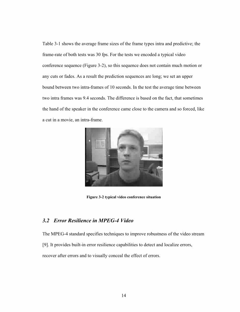
Table 3-1 shows the average frame sizes of the frame types intra and predictive; the
frame-rate of both tests was 30 fps. For the tests we encoded a typical video
conference sequence (Figure 3-2), so this sequence does not contain much motion or
any cuts or fades. As a result the prediction sequences are long; we set an upper
bound between two intra-frames of 10 seconds. In the test the average time between
two intra frames was 9.4 seconds. The difference is based on the fact, that sometimes
the hand of the speaker in the conference came close to the camera and so forced, like
a cut in a movie, an intra-frame.
Figure 3-2 typical video conference situation
3.2 Error Resilience in MPEG-4 Video
The MPEG-4 standard specifies techniques to improve robustness of the video stream
[9]. It provides built-in error resilience capabilities to detect and localize errors,
recover after errors and to visually conceal the effect of errors.

15
Flexible re-synchronization markers help the decoder to ignore invalid or identify lost
data. The encoder can use data partitioning and header protection to organize the
stream to make it more robust to transmission errors by providing redundancy for
important fields of the bit stream.
The long predictive sequences used by MPEG-4 cause propagation and persistence of
errors to increase. The addition of a reference-frame would cause resynchronization
and stop the propagation effects.
MPEG uses variable length coding; this coding allows high compression rates, but is
very sensitive to bit errors. To minimize the effects of bit errors in this coded data, the
MPEG-4 standard supports reversible variable length coding (RVLC). Data coded in
reversible length coding can be decoded in forward and reverse direction without
significant impact on the coding efficiency; so a single bit error would not make the
coded data unusable. This feature also ensures that bit errors do not propagate in a
frame.
Based on the low redundancy observable errors may be more severe compared to
MPEG-2, and since MPEG-4 uses long prediction sequences their effects may persist
longer. MPEG-4 does not target the high demanding environments as MPEG-2 does,
so usually the higher quality reduction caused by bit errors is acceptable.
16
3.3 Effects of errors on Video Quality
To decode a bit stream with inter frame dependencies successfully, the preceding I-
frame and P-frames are needed. The impact of a missing I-frame is significantly
bigger than the loss of a P-frame. The effects of bit errors and data loss in a MPEG-4
bit stream are widely studied [22,34,35].
0
5
10
15
20
25
30
35
0.01 0.05 0.1
bit error rate
PSN
R in
db
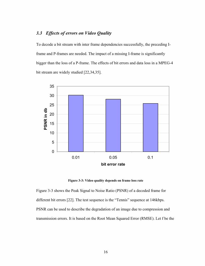
Figure 3-3: Video quality depends on frame loss rate
Figure 3-3 shows the Peak Signal to Noise Ratio (PSNR) of a decoded frame for
different bit errors [22]. The test sequence is the “Tennis” sequence at 146kbps.
PSNR can be used to describe the degradation of an image due to compression and
transmission errors. It is based on the Root Mean Squared Error (RMSE). Let f be the

17
original image and f’ the degraded image, both with size NxM , the RMSE can than
be calculated by the following formula (Formula 3-1):
( ) ( )( )∑∑−
=
−
=
−=1
0
1
0
2,',*1 N
x
M
y
yxfyxfMN
RMSE
Formula 3-1: Root Mean Squared Error (RMSE)
A zero RMSE would be computed for identical image. The PSNR is derived from the
RMSE by denoting it to db. So for an eight bit value with values from 0 to 255, the
PSNE can be calculated with the given Formula (Formula 3-2):
RMSELogPSNR 25520 10=
Formula 3-2: Peak Signal Noise Ratio (PSNR)
PSNR and RMSE can be calculated for both luminance and chrominance of a given
image and than averaged to compute an overall PSNR value. An image with PSNR
below 20 is usually not viewable, values above 25 are acceptable. Please note that the
PSNR is a mathematical way to describe image degradation, the subjective quality
may differ.
The MPEG-4 error recovery ensures a minimal quality degradation due to bit errors
and since internet streaming has a low bit error rate, bit errors are not a concern.
However, encryption is an issue. A bit error in an encrypted bit stream unpredictably
garbles the decrypted bit stream and makes decoding impossible. As a result such a
garbled frame has to be considered a lost one.

18
A frame can be lost due to multiple reasons, the frame could either be lost during
transmission or bit errors make it unusable. N. Feamster shows in his research [16]
that the loss of a P-frame has minor impact on the video quality, while a lost I-frame
causes a high quality decrease and long error propagation.
Figure 3-4 the effects of frame loss on the frame rate with a certain PSNR, figure taken from [16]
His research [16] states that recovery only from I-Frame loss is as efficient as
recovery from all lost P-frames (see Figure 3-4). Since an I-frame is only emitted into
the stream about every 10 seconds, the quality degradation caused by the loss of one
intra-frame is high compared to the quality degradation caused by the loss of a
predictive frame.
19
The reason is simple: A P-frame describes the differences to the previous frame; it
uses the same motion vectors as the previous frame. An I-frame, nevertheless,
introduces a new set of motion vectors. When an I-frame is lost, the succeeding P-
frame will be decoded with motion vectors based on the wrong set.
Since the main target of low-delay real-time streaming is video conferencing, we do
not have a high demanding environment. The errors caused by loss of a P-frame can
be accepted, but the ones caused by the loss of an I-frame cannot be accepted due to
their high quality decrease.
Based on this we introduce our model: Since retransmission of a frame is not possible
due to real-time concerns, we can use the resynchronization packets introduced by the
draft [13] for immediate feedback of RTP sessions. If a receiver losses a packet, it
will send this resynchronization packet to the transmitter. Upon receiving such a
resynchronization request, the encoder will base further encoding on the image, the
request refers to. Since each frame contains the number of the image its coding is
based on, the decoder can resynchronize itself upon receiving the frame containing
the resynchronized image. This solution would guarantee that after a certain
transmission delay the error propagation would be stopped. The approach
accomplishes the goal of stopping the error propagation and guarantees a low RMSE,
but the price is a high overhead. For every lost packet a response is send by the
receiver, especially in wireless environments this may be required often. In addition
there is a high computational overhead when encoder and decoder have roll back and
base the prediction on another image. Much data has to be held for that, especially for

20
mobile devices with low performance this may be an issue. In the paragraph before
we have realized that the loss a P-frame does not have big impact on the quality.
So the appropriate approach would be only to send the resynchronization message
when a reference frame (I-frame) has been lost.
3.3.1 Custom RTP header addition
Since RTP and MPEG-4 do not provide controls to detect the loss of a certain frame
type, we add an additional header between the RTP header and the payload. The RTP
standard is defined very flexible, custom headers can be added without impact on
compatibility. The new header introduces sequence numbers for key frames and so
allows the receiver to detect key frame loss.
This value is a 4 byte (to keep byte alignment) sequence number added between the
RTP-Header and RTP-payload as described in the RTP definition (section 5.3) [2].
3.3.2 Immediate RTP feedback
To signal the loss of a key frame, we send an immediate RTCP feedback packet. This
packet is built analog to the instant feedback packet introduced in [13].
21
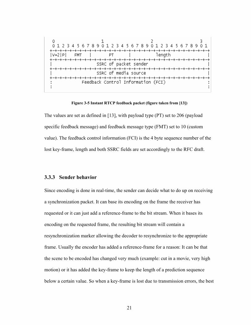
Figure 3-5 Instant RTCP feedback packet (figure taken from [13])
The values are set as defined in [13], with payload type (PT) set to 206 (payload
specific feedback message) and feedback message type (FMT) set to 10 (custom
value). The feedback control information (FCI) is the 4 byte sequence number of the
lost key-frame, length and both SSRC fields are set accordingly to the RFC draft.
3.3.3 Sender behavior
Since encoding is done in real-time, the sender can decide what to do up on receiving
a synchronization packet. It can base its encoding on the frame the receiver has
requested or it can just add a reference-frame to the bit stream. When it bases its
encoding on the requested frame, the resulting bit stream will contain a
resynchronization marker allowing the decoder to resynchronize to the appropriate
frame. Usually the encoder has added a reference-frame for a reason: It can be that
the scene to be encoded has changed very much (example: cut in a movie, very high
motion) or it has added the key-frame to keep the length of a prediction sequence
below a certain value. So when a key-frame is lost due to transmission errors, the best
22
way would be to add another key-frame to the stream. This solution has a minimal
overhead, since no encoder or decoder rollback is required. To match bandwidth
limitations the number of key frames added to the bit stream per second has be kept
below a certain value.
Since this approach does not do any changes to the MPEG bit stream, it can be used
in combination with error concealment techniques and post processing tools to limit
the effects of bit stream errors or the loss of prediction frames.
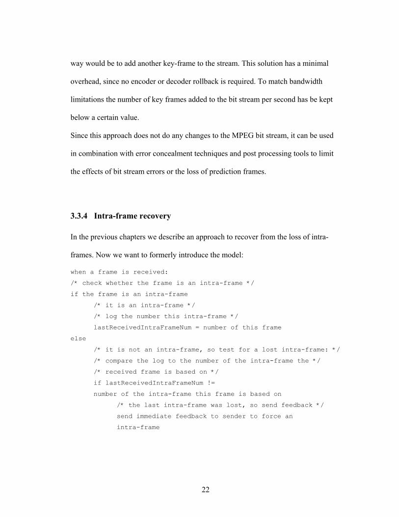
3.3.4 Intra-frame recovery
In the previous chapters we describe an approach to recover from the loss of intra-
frames. Now we want to formerly introduce the model:
when a frame is received: /* check whether the frame is an intra-frame */ if the frame is an intra-frame /* it is an intra-frame */ /* log the number this intra-frame */ lastReceivedIntraFrameNum = number of this frame else /* it is not an intra-frame, so test for a lost intra-frame: */ /* compare the log to the number of the intra-frame the */ /* received frame is based on */ if lastReceivedIntraFrameNum != number of the intra-frame this frame is based on /* the last intra-frame was lost, so send feedback */
send immediate feedback to sender to force an intra-frame
23
3.4 Error Resilience in MPEG-4 Audio
The AAC audio standard specifies profiles (Long Term Prediction, LTP and Low
Delay, LD) [9,10] with no inter frame dependencies. The Long Term Prediction uses
a backward prediction based on preceding frames to optimize compression, while the
LD profile adds an encoder and decoder model with low delay (LD). The quality
differences of the LTP and LD profiles to the main profile are minimal. The good
encoding quality of these two profiles and the fact that transmission errors and data
loss will only effect the actual frame, no error propagation will occur, make these
profile ideal for streaming.
The error robustness and error protection in MPEG-4 AAC reduces the perceived
degradation of the decoded audio data caused by bit corruption. The techniques of the
audio error resilience features are similar to the ones of video (see chapter 3.2).
3.5 Effects of errors on Audio Quality
Without error protection and resilience features turned on, tests [36] have shown that
bit error rates up to 310− are acceptable. When these tools get turned on, the quality of
the erroneous (error rate: 310− ) and the error-free stream are nearly equivalent. Since
errors cannot propagate from frame to frame no retransmission model is introduced
for audio.
24
3.6 Summary
In this chapter we evaluated the effect of transmission errors on the video and audio
quality of a MPEG-4 bit stream. Since lost audio frames do not cause error
propagation, no additional techniques are needed to handle audio frame loss.
However, lost video frames cause error propagation. We presented a technique to
reduce the effects of lost video frames, thereby focusing on environments with real-
time concerns. These real-time systems allow us, to take advantage of the fact that
encoding is done live and so we can base encoding on the feedback from the receiver.
The reader may note, that our approach adds low overhead to the bit stream and does
not influence post processing and error resilience capabilities while it is conform with
the RTP RFC [2,3].
25
4 Bandwidth adaptation
The conditions of the internet regarding available bandwidth change with time. Not
adjusting to these conditions will result in random packet loss and non friendly
behavior to other applications with which the bandwidth is shared.
To deliver a stream in the highest possible quality for a given bandwidth a real-time
application has to adjust its bit rate to the changing conditions. To adjust properly an
application should:
• Adapt to the loss of packets: For example by adding a key frame for
resynchronization, as shown in chapter 3.
• Adjust the quality (bit-rate) of the stream to the available bandwidth.
For applications with no real-time constraints the solution is easy: They can afford a
long buffer time, so they could just buffer up a huge amount of data during start. This
buffer is used to smoothen bandwidth oscillations. Many of today’s applications use
this approach [37,38,39]. For applications with real-time constraints this approach is
not feasible. This chapter discusses a congestion control that is usable for real-time
streaming. We introduce TCP-friendly binominal congestion control, which is a
superset of the TCP congestion control algorithm. In our model we only use a small
buffer to accommodate transmission jitter. We will show that by using SQRT [28], a
member of the binominal congestion control algorithm family, we can achieve:
• TCP-friendly bandwidth adaptation
• Reduce rate oscillations

26
4.1 Congestion Control
Due to variations in the available bandwidth, congestion occurs; it occurs at
transmission bottlenecks. Since unlimited buffering is not possible at these
bottlenecks, random packet loss will be the result. During a TCP-transmission a
successful delivery of a packet is acknowledged by the receiver; based on this
feedback the transmitter will reduce or increase its bit-rate. Since streaming is usually
based on UDP, such an acknowledgement is not sent. So the RTCP control messages
sent by the receiver have to be used to detect packet loss and to adjust to bandwidth
bottlenecks.
When during a TCP-transmission a packet loss is detected the sender will reduce its
bit rate by half and than slowly increase it until the next packet loss is detected. This
results in a high oscillation of the bit rate. While during file transfers high oscillations
of the throughput are not an issue, high oscillations during real-time streaming would
result in a non smooth playback. So the traditional additive increase / multiple
decrease (AIMD) [40] used by the TCP congestion control algorithm is not feasible
for streaming media. We need an algorithm that also probes for bandwidth and
reduces its throughput up on congestion like AIMD does, but is should not introduce
high oscillations. Another requirement of our algorithm is TCP-friendliness to
guarantee fair bandwidth sharing.
27
4.2 Variable bit rate encoding
The MPEG-4 video standard allows video to be encoded at variable bit rates. Since
the video is encoded in real-time, the available bit rate of the link can be feed in the
encoder. This allows great advantages compared to non real-time encoding systems.
Non real-time encoding systems have to store the streams in various bit rates to
satisfy the changing conditions of a link. This is not an optimal solution, since
streams cannot be stored in every possible transmission rate and it introduces storage
and computing overhead. Scalable encoding may reduce the amount of stored data
needed, but still does not allow to support all bit-rates. Variable bit-rate encoding
done in real-time allows adjustment to the changing conditions in an optimal way.
4.3 TCP friendliness
The reasons for implementing a congestion control into an application are simple:
• An application with congestion control makes more efficient use of the
network this usually results in higher performance.
• Applications are capable of running over a much wider range of bandwidths,
if they adjust to the changing conditions. This makes them more useful in the
Internet.
• Fair congestion control algorithms prevent the network from overload and so
an congestive collapse
28
So to be safe for use in the Internet an application has to implement a protocol with
congestion control. Its congestion control algorithm has to be stable and interact well
with the existing widely used TCP. This type of protocol is TCP-friendly [41],
ensuring that traditional TCP transmissions based in the AIMD algorithm get a fair
allocation of bandwidth while sharing a link with such an application and vice versa.
It now can be argued that a real-time transmission should have a higher priority than
traditional TCP-transmission because the TCP-connection usually does not have real-
time constraints. However, this claim cannot be judged, since today’s internet does
not provide quality of service nor prioritize traffic, and not all traffic that is
transmitted through a link is our traffic. Based on that, all applications should be
TCP-friendly, especially because streaming is meanwhile widely used and so its
percentage of the internet traffic increases.
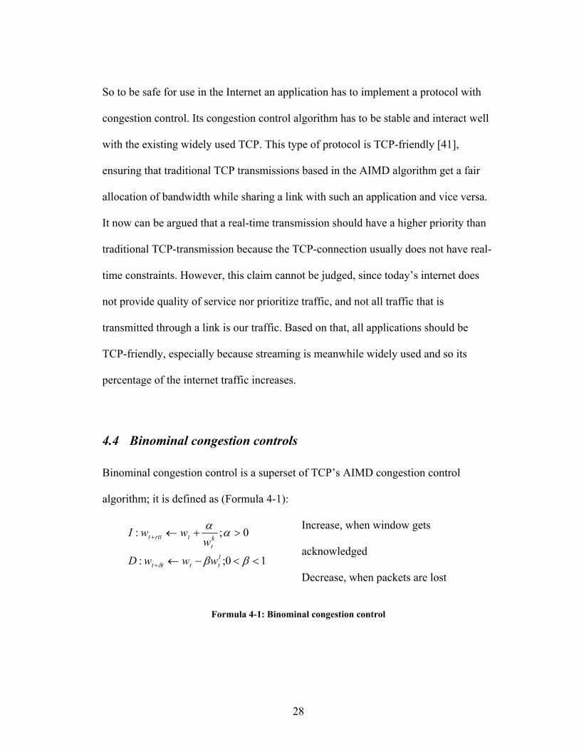
4.4 Binominal congestion controls
Binominal congestion control is a superset of TCP’s AIMD congestion control
algorithm; it is defined as (Formula 4-1):
Increase, when window gets
acknowledged 10;:
0;:
<<−←
>+←
+
+
ββ
αα
δltttt
kt
trttt
wwwD
wwwI
Decrease, when packets are lost
Formula 4-1: Binominal congestion control

29
Let I be the increase of the window size (in packets) as a result of an acknowledged
reception, with rtt being the round trip time. D describes a decrease of the window
size (again in packets) as an effect of a packet loss. α and β are constants.
This generalization includes the entire linear algorithms:
• For 1,0 == lk : AIMD (additive increase, multiple decrease)
used by TCP
• 1,1 =−= lk : MIMD (multiple increase, multiple decrease),
used by the slow start algorithm in TCP
• 0,1 =−= lk : MIAD (multiple increase, additive decrease)
• 0,0 == lk : AIAD (additive increase, additive decrease)
In our model we use the values 5.0,5.0 == lk . This algorithm is called SQRT,
because the increase is inversely proportional and the decrease is proportional to
square-root of the window size. Research [28,42] has shown that this algorithm is
TCP-friendly and achieves lower bit rate oscillations than traditional TCP-
algorithms. In the AIMD algorithm the window size reduction is proportional to
windows size, while in SQRT it is proportional to the square-root of the window
size; as a result the window size oscillations are less. This makes this algorithm a
perfect candidate for media streaming.
In their research [42] D. Bansal and H. Balakrishnan suggest values for βα ,
which satisfy the condition ]7.0..5.0[/ =αβ . We choose the values
6.0,1 == βα as it is done in their paper. Figure 4-1 shows the lower oscillations

30
and still fair bandwidth share of SQRT compared to TCP’s AIMD congestion
control algorithm.
Figure 4-1: Window size of SQRT and AIMD (TCP) congestion control
4.5 Congestion control in RTP
Since UDP and RTP protocols do not send acknowledgements for received packets, a
different approach has to be taken to detect packet loss and allow congestion control.
The RTP connection would send control packets in different intervals. The control
packets allow the detection of lost packets. A linear congestion control model, which
uses these control messages for congestion detection, has been introduced [26]. In our
model we combine this model and the binominal congestion control algorithm SQRT
for smooth data throughput.
In a RTP-session the receiver frequently sends report packets for each incoming
stream. The report packet includes the total amount of lost data, the fraction of data
lost since the last report was send, the RTP-timestamp of the last received sender
31
report, and a timestamp indicating the time elapsed between receiving the last sender
report and sending this receiver report. When the sender knows the time of arrival of
such a receiver report it can compute the round trip time.
Let t be the arrival time of the receiver report, DLSRt the time elapsed between
receiving the last sender report and sending the receive report and LSRt the RTP-
timestamp of the sending of the last sender report. The round trip time rttt can be
calculated the following way (Formula 4-2):
LSRDLSRrtt tttt −−=
Formula 4-2: Round trip time (RTT)
The reader may note that is calculation does not require clock synchronization of the
participants and so can be considered accurate.
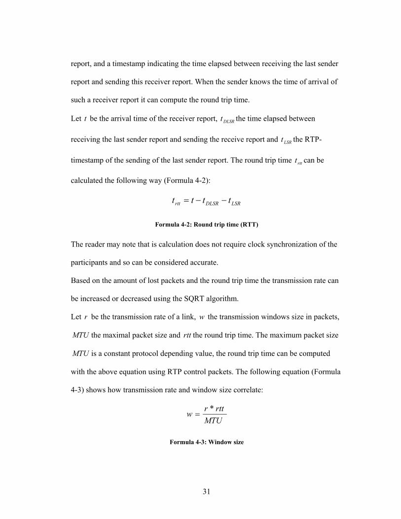
Based on the amount of lost packets and the round trip time the transmission rate can
be increased or decreased using the SQRT algorithm.
Let r be the transmission rate of a link, w the transmission windows size in packets,
MTU the maximal packet size and rtt the round trip time. The maximum packet size
MTU is a constant protocol depending value, the round trip time can be computed
with the above equation using RTP control packets. The following equation (Formula
4-3) shows how transmission rate and window size correlate:
MTUrttrw *
=
Formula 4-3: Window size
32
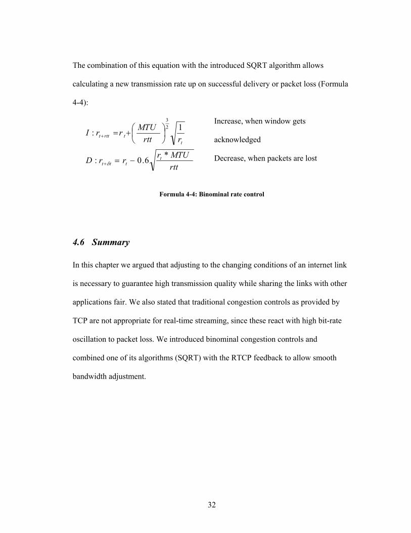
The combination of this equation with the introduced SQRT algorithm allows
calculating a new transmission rate up on successful delivery or packet loss (Formula
4-4):
Increase, when window gets
acknowledged
rttMTUrrrD
rrttMTUrrI
tttt
ttrttt
*6.0:
1:23
−=
+=
+
+
δ
Decrease, when packets are lost
Formula 4-4: Binominal rate control
4.6 Summary
In this chapter we argued that adjusting to the changing conditions of an internet link
is necessary to guarantee high transmission quality while sharing the links with other
applications fair. We also stated that traditional congestion controls as provided by
TCP are not appropriate for real-time streaming, since these react with high bit-rate
oscillation to packet loss. We introduced binominal congestion controls and
combined one of its algorithms (SQRT) with the RTCP feedback to allow smooth
bandwidth adjustment.

33
5 Security
In this chapter we focus on the problems of security [43]. For streaming the security
issues are the same ones as for traditional communications, such as fraud,
eavesdropping and prevention of communication. We add security to our model to
ensure that the requirements everyone has for communication cannot be subverted by
other people.
5.1 Security Requirements
To ensure the privacy we have to guarantee:
• Data Integrity:
Mechanisms prohibiting and detecting substituted, appended or removed data
have to be in place
• Authentication:
The sender of the stream has to be authenticated; often also the receivers must
have authorization to receive it.
• Confidentiality:
It should be not possible that someone not authorized is able to see the content
of a transmission

34
• Key Distribution:
To ensure confidentiality usually encryption is used, a mechanism has be in
place to allow the save distribution of keys the decrypt the received data.
ACE (Ambient Computing Environment, see chapter 2.6) implements save
mechanisms for authentication and key distribution. We will use these for our project.
To allow interoperation with ACE and to guarantee a high security-level our model
has to allow a key-change at any time, even during a transmission
Streaming of media for interactive sessions has real-time constraints, the algorithms
used to ensure integrity and confidentiality have to be fast.
5.2 Suitable Algorithms
Since our system requires strong real-time encryption done without additionally
hardware, a “software friendly” encryption algorithm is needed. Here “software-
friendly” refers to an algorithm that can be implemented in software efficiently. DES
(Data Encryption Standard) [44] and Triple DES are outdated, not secure enough for
today’s applications and not “software friendly”. In addition public / private key
cryptography is not suitable, since it is too slow. So the preferred algorithm is AES
(Advanced Encryption Standard) [48] for cryptography; AES is “software-friendly”
and supports key length of 128, 192 and 256 bits. 128 bit keys are considered safe for
today’s applications.
35
MD-5 (Message Digest) [45] is a fast hashing algorithms, but based on its design and
hash length [46], we do not consider it safe enough. Although SHA-1 (Secure Hash
Algorithm) [47] is a slower than MD5, its design and hash length [46] offers the
security needed.
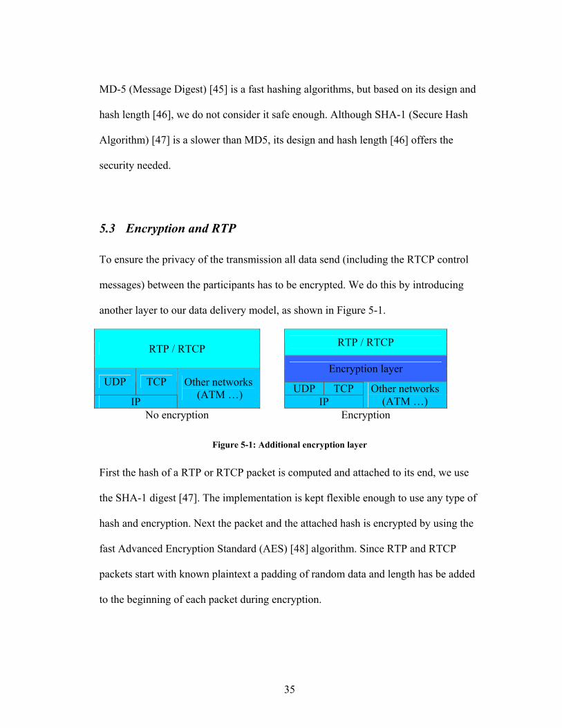
5.3 Encryption and RTP
To ensure the privacy of the transmission all data send (including the RTCP control
messages) between the participants has to be encrypted. We do this by introducing
another layer to our data delivery model, as shown in Figure 5-1.
RTP / RTCP RTP / RTCP Encryption layer
UDP TCP UDP TCP IP
Other networks (ATM …) IP
Other networks (ATM …)
No encryption Encryption
Figure 5-1: Additional encryption layer
First the hash of a RTP or RTCP packet is computed and attached to its end, we use
the SHA-1 digest [47]. The implementation is kept flexible enough to use any type of
hash and encryption. Next the packet and the attached hash is encrypted by using the
fast Advanced Encryption Standard (AES) [48] algorithm. Since RTP and RTCP
packets start with known plaintext a padding of random data and length has be added
to the beginning of each packet during encryption.

36
Upon delivery the receiver can now decrypt the message using the key delivered by
the ACE security framework [49]. Than it can compute the hash of the received data,
and compare it to the hash delivered with the data. While the encryption guarantees
confidentiality the combination of encryption and hash ensure integrity. When due to
transmission errors the computed hash does not be equal to the hash that was attached
to a received packet, the received packet is not useful anymore. There are no ways to
restore it, this is based on a characteristic of encryption: Does one bit of a packet get
changed, the rest of the decoded packet will be randomly garbled.
Figure 5-2: Encrypted RTP / RTCP packet
5.4 Summary
In this chapter we proposed an approach for secure transmission of RTP sessions. We
encrypt both RTP and RTCP packets. This allows hiding the complete
communication in the traffic of the internet. Since also the RTP and RTCP headers
are encrypted it is even very hard to detect that this communication consists of real-
UD
P H
eade
r
Padd
ing
RTP
/ R
TCP
Hdr
.
Dat
a
Has
h
Padd
ing
: Encrypted

37
time audio and video data. The only way to detect this is an analysis of the timely
fashion of the traffic flow, since RTCP sends characteristic feedback packets.
38
6 Implementation
This chapter describes our experience with implementing these models into a video
and audio streaming system. It describes the interaction with existing capture and
playback tools, codecs and the ACE system.
6.1 Platform
We use Java [50] and the Java Media Framework (JMF) [51] for our implementation.
This gives certain platform independence, since Java interpreters are available for a
huge number of systems. The Java Media Framework also exists as pure Java version
allowing its execution on all Java interpreters. In addition high performance system-
depending versions are available, they allow capturing and fast playback of video and
audio and support more codecs. These additional codecs are written in C to guarantee
high performance for encoding and decoding.
Currently high performance versions are available for Linux, Windows and Solaris.
6.1.1 Java Media Framework
The Java Media Framework (JMF) provides a flexible framework to integrate time
based media into Java applications. The JMF API is build from several layers. Data
sources, players and processors are the essential parts of the high level API; they
manage capture, presentation and processing of media. The lower API supports the

39
flexible integration of custom extensions and components. This offers a simple and
powerful API to build media support into java applications, while keeping the
framework flexible enough for future extensions to support new media types and
formats.
Java Application
JMF High Level API
JMF Plug-In API
Codec Effect Source Renderer Multiplex
Figure 6-1: JMF API architecture
In addition to capture, presentation and processing of audio and video data, the
framework supports different file types and the streaming of data. It supports RTP
and RTSP, and allows the synchronization of streamed and non-streamed media.
Figure 6-2: Processing media with the JMF
In the Java Media Framework processors (Figure 6-2) allow to manipulate media.
This allows encoding, packetizing for streaming, multiplexing, pre- and post-
processing. Examples for pre- and post processing are gain control or resizing.
Data source Data source Processor

40
Multiple Processors can be connected to manipulation chains, or can process audio
and video data parallel.
6.1.2 Sound in Java and JMF
JMF supports sound capture and playback via the Java Sound API [52]. The Java
Sound API is not made for real-time capture and playback since it delays the data due
to huge buffer sizes. The typical delay of the Java Sound API is about 200ms, this
might not be a problem for normal playback and capture, but for real-time
applications this is inappropriate.
To solve this problem we implemented a new JMF low-delay audio data-source and
renderer based on Java Native Interface JNI [53] calls to the Advanced Linux Sound
Architecture ALSA [54].
Now the delay is only limited by the system hardware, load and scheduling. On
systems with a good soundcard (we used Sound Blaster Live) we were able to achieve
delays below 30ms for capture and playback; these systems were equipped with
average hardware (dual Pentium III, 700 Mhz, 1GB RAM) and driven under high
load (>90% CPU load). For full-duplex (simultaneous capture and playback) we
achieve delays below 60ms on these systems. Based on the implementation, an audio
frame has a size of a third of the delay. So the 60ms delay results in delivering every
20ms an audio frame of 20ms length. A MPEG-4 AAC audio frame has a size of
1046 samples, which equals about 23 ms when sampling at 44.100 kHz, this matches
well with the capture and playback frame sizes we achieved.
41
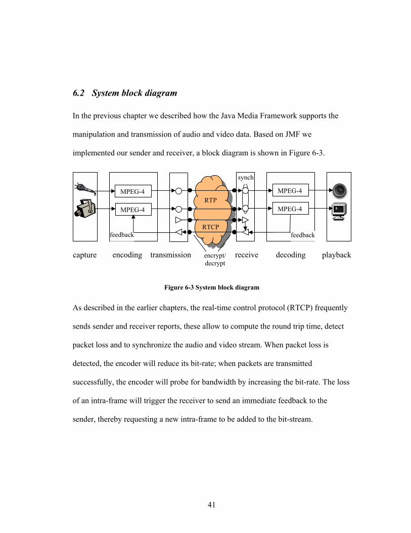
6.2 System block diagram
In the previous chapter we described how the Java Media Framework supports the
manipulation and transmission of audio and video data. Based on JMF we
implemented our sender and receiver, a block diagram is shown in Figure 6-3.
Figure 6-3 System block diagram
As described in the earlier chapters, the real-time control protocol (RTCP) frequently
sends sender and receiver reports, these allow to compute the round trip time, detect
packet loss and to synchronize the audio and video stream. When packet loss is
detected, the encoder will reduce its bit-rate; when packets are transmitted
successfully, the encoder will probe for bandwidth by increasing the bit-rate. The loss
of an intra-frame will trigger the receiver to send an immediate feedback to the
sender, thereby requesting a new intra-frame to be added to the bit-stream.
RTCP
RTP
capture
MPEG-4
MPEG-4
feedback
encoding transmission
MPEG-4
MPEG-4
feedback
synch
playbackdecoding receive encrypt/ decrypt

42
6.3 MPEG-4 Codecs
Since the MPEG-4 reference implementation does not offer the performance and
quality needed for real-time encoding and decoding of audio and video data, we use
newer implementations. The described codecs are written in C, C++ or assembler
code, we access their APIs by using the Java Native Interface JNI [53].
The following codec versions are used:
• MPEG-4 video codec XVID [55], version 0.9.0
• MPEG-4 and H.263 video codecs of FFMPEG [56], stable cvs snapshot from
the 9th of August 2003
• MPEG-4 audio encoder FAAC [58], version 1.17b
• MPEG-4 audio decoder FAAD2 [58], version 1.1
The versions of the codecs we have tested compile on standard systems like Linux
and Windows. Many also compile and work on Macintosh and PDAs.
Most of these codecs are still under continuous development, the current versions
[55,56,58] support the basic and some advanced features of the huge MPEG-4
standard. The profiles and modes supported are sufficient for real-time streaming,
since advanced modes are more complex and so increase the time needed to encode
and decode a frame. This implementation has to meet real-time constraints, so the use
of basic and some advanced features is enough due to the limited processing power.
Please note, that since we are using open source codecs, their quality might be less
than the quality of commercial MPEG-4 video and audio codecs. Due to the flexible

43
architecture of the Java Media Framework and our additions to it, other codec
versions or even new codec types can be added when required.
In our model we did not implement any pre- or post-processing in addition to the
error concealment features of MPEG-4 to keep the amount of processing low. Since
the JMF architecture supports processor chains, this can be added very easily if
needed.
6.3.1 MPEG-4 Video Codec
For MPEG-4 video we use the XVID codec [55], in addition we implemented an
interface to FFMPEG [56]. FFMPEG provides a codec suite; we use their h.263 [6]
and MPEG-4 video codecs. H.263 allows the support of systems with lower
performance. JMF also offers a H.263 codec, but we prefer the FFMPEG version,
since it offers more control.
The MPEG-4 codecs support bit rates from well below 60 kbps up to more than 900
kbps. The quality of a bit stream encoded with a certain bit rate mainly depends on
the resolution and the motion of the input. For video conferencing applications this is
a great advantage, since a video conference usually does neither contain much motion
(compared to a movie) nor cuts or fades. Each cut or fade has to be encoded in a
reference frame, since the data to base prediction on has changed completely.
To match a requested bit rate the encoder uses different types of quantizers,
quantization values and motion compensation methods. While the type of the
quantizer and motion compensation model used usually does not change during
44
encoding, the quantization value gets recomputed for each frame to encode; the
quantization value has the most influence on the resulting bit rate. Since we encode
each frame only once and the quantization value has to be determined before
encoding, an appropriate value has to be estimated based on preceding frames, bit-
rate to match, size and motion of the input image and the type of frame to code.
Not only the average bit-rate is important for streaming media, it also important to
keep the deviation from this value small, since a link has a maximum throughput. As
intra-frames are significantly bigger than forward or bidirectional predictive-frames,
they usually get encoded with a higher quantization values to keep their size and the
deviation from the streaming rate small, and so do carry a less detailed image than
other frame types.
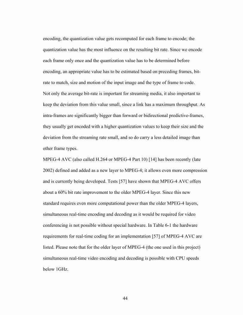
MPEG-4 AVC (also called H.264 or MPEG-4 Part 10) [14] has been recently (late
2002) defined and added as a new layer to MPEG-4; it allows even more compression
and is currently being developed. Tests [57] have shown that MPEG-4 AVC offers
about a 60% bit rate improvement to the older MPEG-4 layer. Since this new
standard requires even more computational power than the older MPEG-4 layers,
simultaneous real-time encoding and decoding as it would be required for video
conferencing is not possible without special hardware. In Table 6-1 the hardware
requirements for real-time coding for an implementation [57] of MPEG-4 AVC are
listed. Please note that for the older layer of MPEG-4 (the one used in this project)
simultaneous real-time video encoding and decoding is possible with CPU speeds
below 1GHz.

45
Codec CPU Speed Memory
Encoder Pentium IV 3.0 GHz 512 MB
Decoder Pentium IV 2.0 GHz 256 MB
Table 6-1: Hardware requirements for MPEG-4 AVC real-time coding;
the AVC layer is inappropriate for simultaneous real-time encoding
and decoding with today’s hardware.
6.3.2 MPEG-4 Audio Codec
For audio MPEG-4 / MPEG-2 AAC audio is used, this is provided by the FAAC
codec [58]. In addition we support GSM [61] and G.723 [60] for systems with lower
performance and very low bandwidth links. The GSM and G.723 codecs are provided
by the Java Media Framework.´
MPEG-4 AAC offers high quality audio encoding at low bit rates. Tests [59] indicate
that AAC offers a 1/3 greater compression than the widely used MPEG-1 layer III (so
called: “mp3”) compression. So has a stereo signal encoded in AAC with a bit rate of
96 kb/s a better quality than “mp3” at 128 kb/s.
AAC is a block oriented variable bit rate algorithm. The sender reads 1024 (LD
profile: 996) samples from the input and writes a number of output bits in relation to
the desired bit rate. Each of the encoded blocks of 1024 input samples can be decoded
independently from each other and so the loss or corruption of a bit in the stream has
minimal influence, since error propagation is only possible in the current frame.

46
Like in the video part a new layer has been added to MPEG-4: MPEG-4 HE AAC
(also called: AAC Plus) [15] has been recently (late 2002) defined; it allows even
more compression and is currently under heavy development. As with the new video
layer, the hardware requirements to not allow simultaneous real-time encoding and
decoding with today’s systems.
0
20
40
60
80
100
Referen
ce
AAC-Plus
MP3Pro
AAC
WMA 8MP3
Qua
lity
in %
of r
efer
ence
Quality
Figure 6-4: Codec test [59] at 48 kbps stereo
Figure 6-4 shows a quality comparison of different audio coding standards, these
graphs are based on a subjective listening test [59], carried out by the European
Broadcasting Union in 2002.

47
6.4 Low performance codecs
To support systems with low performance, we added support for codecs that do not
require so much computation.
As mentioned H.263 video coding is supported, we also added the low bit-rate speech
codecs G.723 (6.3 kbps) [60] and GSM (13.2 kbps) [61], these focus on the coding of
speech only and so result in lower bit rates. The MPEG-4 standards suite also defines
speech codecs, these are still under heavy development and will not be used in this
project.
6.5 RTP
The Java Media Framework provides an implementation of RTP and RTCP. Media
Streams can be transmitted and received; Quality of Service can be controlled via
RTCP control packets. JMF also takes care of the synchronization of multiple streams
transmitted from the same source. We use the flexible RTP implementation JMF
provides to add quality and congestion control features as described in chapters 3 and
4. Later we added the security features described in chapter 5. All these additions to
the Java Media Framework could be made, because the framework is kept very
flexible.

48
6.5.1 RTP and MPEG-4
For each source the RTP standard defines that a separate stream is needed, thereby
reducing multiplexing overhead. Streams of the same source can be synchronized by
the receiver using the time stamps from the control packets (RTCP).
RFC 3016 [12] describes the direct mapping of video and audio streams on RTP-
packets without using the MPEG-4 systems standard. This allows using for example a
MPEG-4 video stream and non MPEG-4 audio stream for a session. It also keeps
multiplexing overhead low. In addition a RFC draft [13] introduces a new RTCP
packet for the resynchronization feature of MPEG-4 streams. We use this packet type
to signal the loss of a key frame as described in chapter 3.
The RFC introduces a quite simple mapping of frames on RTP packets. One MPEG-4
frame (either video or audio) gets mapped in one RTP packet. If the resulting RTP
packets are too small for efficient transmission, multiple frames can be mapped on
one packet. One frame should not be mapped on two or more packets, except its size
exceeds the maximal packet size (MTU) of the underlying protocol. Figure 6-5 and
Figure 6-6 describe the effects of inadequate mapping of video packets when a packet
gets lost during transmission.

49
Figure 6-5: Low impact of packet loss due to good mapping
Figure 6-6: High impact of packet loss due to inappropriate mapping
Since UDP is mostly used for real time transmission over the internet and UDP
supports packets up to a size of about 64kbyte, a MPEG-4 frame usually does not
exceed the maximal packet size of UDP. Depending on the network type the UDP
packets are transmitted on, some lower network layer may perform fragmentation.
But since the fragmentation depends on the link and the used lower layer network
protocol, the fragmentation has to be performed by these layers to achieve optimal
link utilization.
Since MPEG-4 audio and video has build in error resilience capabilities, no additional
RTP-Header as in H.261 and MPEG-2 / MPEG-1 is needed for error recovery. To
RTP
Hdr
V
OP
Hdr
Dat
a
RTP
Hdr
V
OP
Hdr
Dat
a
RTP
Hdr
V
OP
Hdr
Dat
a
Packet complete Packet lost Packet complete R
TP H
dr
VO
P H
dr
Dat
a
RTP
Hdr
VO
P H
dr
Dat
a
VO
P H
dr
RTP
Hdr
Dat
a
Packet incomplete Packet lost Packet incomplete
50
detect lost key-frames, we added a new RTP-Header as described in chapter 3 to the
stream.
Since the bandwidth used for audio is only a fraction of the video bandwidth, we
support bandwidth adjustment based on congestion control only for MPEG-4 video.
6.6 Files
Our model supports writing of MPPEG-4 video and audio files. Users can write a
copy of received and send streams to a file system. The system writes separate audio
and video files to avoid multiplexing overhead during run-time. The files than can be
multiplexed to a MPEG-4 systems file (“mp4”) or an “avi-container” by many tools
[62,63]. Playback is possible with most players such as Windows Media Player [38],
Quicktime [39] and MPlayer [64]. For all these players the appropriate codecs for
MPEG-4 files, audio and video have to be installed.
6.6.1 Synchronization
When a frame gets lost or is delayed too long during transmission the Java Media
Framework skips it to keep the video and audio data synchronized. When now both
streams get written on a file system, the audio stream for example may have less
duration than the video stream, due to the skipped frames. The result is, that after
multiplexing, both streams would not be synchronized since the multiplexer does not

51
know which frames got lost. This means during file write, a frame has to be added
where a frame was skipped to keep both streams synchronized during playback.
52
7 Evaluation
In this chapter we describe the evaluation of our models and their implementation
into a video and audio streaming system. We will show that our models enable low-
delay real-time communication, while being to recover from frame loss, adapt to
bandwidth variations and secure the transmission.
7.1 Selective intra-frame addition
A streaming system has to recover from key frame loss to prevent degradation of the
received image. The amount of degradation increases with each received frame and
depends on the amount of movement in the image. This means, recovery has to be
performed as soon as possible. The fact that the amount of degradation depends on
the movement in the image, is an advantage for the applications we target, since for
example a video conference usually has less motion than a movie.
When our system detects the loss of an intra-frame a feedback packet is send to the
transmitter, which than adds another intra-frame to the stream. This new intra-frame
will stop the image degradation. The user will only see a degraded image for the
round trip time of the connection (plus some additional processing time). Since this is
a short time, not much degradation will occur and picture will stay viewable.
53
25
26
27
28
29
30
31
32
1 2 3 4 5 6 7 8 9 10 11 12 13 14 15 16 17
receiver frame number
PSN
R
test 1test 2
frame loss
recovery
360 ms
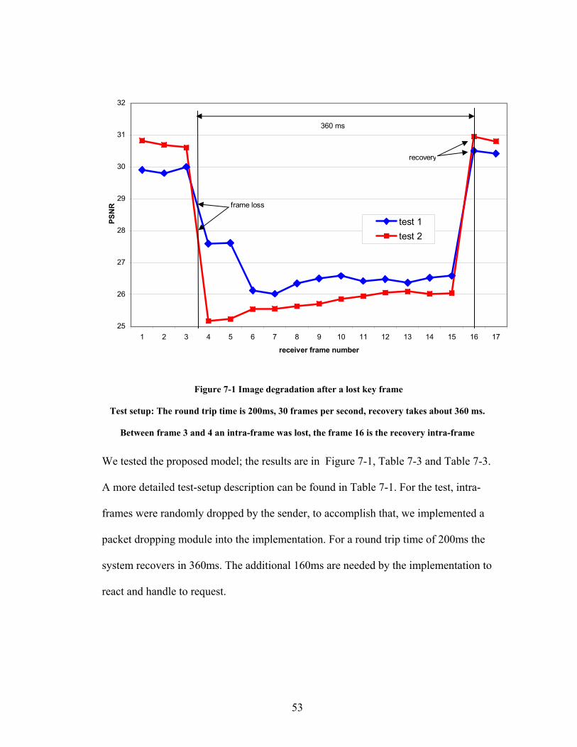
Figure 7-1 Image degradation after a lost key frame
Test setup: The round trip time is 200ms, 30 frames per second, recovery takes about 360 ms.
Between frame 3 and 4 an intra-frame was lost, the frame 16 is the recovery intra-frame
We tested the proposed model; the results are in Figure 7-1, Table 7-3 and Table 7-3.
A more detailed test-setup description can be found in Table 7-1. For the test, intra-
frames were randomly dropped by the sender, to accomplish that, we implemented a
packet dropping module into the implementation. For a round trip time of 200ms the
system recovers in 360ms. The additional 160ms are needed by the implementation to
react and handle to request.
54
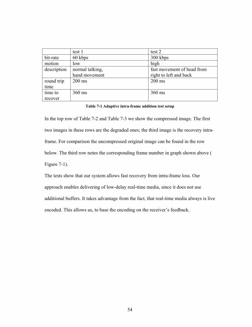
test 1 test 2 bit-rate 60 kbps 300 kbps motion low high description normal talking,
hand movement fast movement of head from right to left and back
round trip time
200 ms 200 ms
time to recover
360 ms 360 ms
Table 7-1 Adaptive intra-frame addition test setup
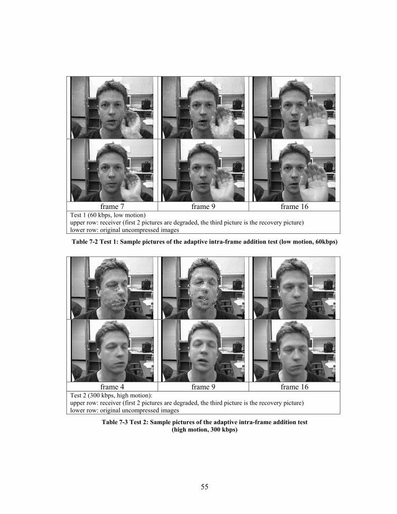
In the top row of Table 7-2 and Table 7-3 we show the compressed image. The first
two images in these rows are the degraded ones; the third image is the recovery intra-
frame. For comparison the uncompressed original image can be found in the row
below. The third row notes the corresponding frame number in graph shown above (
Figure 7-1).
The tests show that our system allows fast recovery from intra-frame loss. Our
approach enables delivering of low-delay real-time media, since it does not use
additional buffers. It takes advantage from the fact, that real-time media always is live
encoded. This allows us, to base the encoding on the receiver’s feedback.
55
frame 7 frame 9 frame 16
Test 1 (60 kbps, low motion) upper row: receiver (first 2 pictures are degraded, the third picture is the recovery picture) lower row: original uncompressed images
Table 7-2 Test 1: Sample pictures of the adaptive intra-frame addition test (low motion, 60kbps)
frame 4 frame 9 frame 16
Test 2 (300 kbps, high motion): upper row: receiver (first 2 pictures are degraded, the third picture is the recovery picture) lower row: original uncompressed images
Table 7-3 Test 2: Sample pictures of the adaptive intra-frame addition test (high motion, 300 kbps)
56
7.2 Bandwidth Adaptation
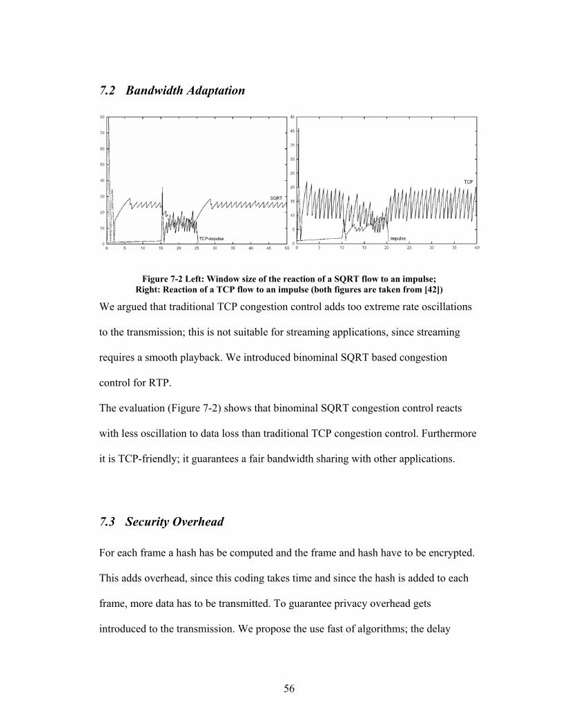
Figure 7-2 Left: Window size of the reaction of a SQRT flow to an impulse; Right: Reaction of a TCP flow to an impulse (both figures are taken from [42])
We argued that traditional TCP congestion control adds too extreme rate oscillations
to the transmission; this is not suitable for streaming applications, since streaming
requires a smooth playback. We introduced binominal SQRT based congestion
control for RTP.
The evaluation (Figure 7-2) shows that binominal SQRT congestion control reacts
with less oscillation to data loss than traditional TCP congestion control. Furthermore
it is TCP-friendly; it guarantees a fair bandwidth sharing with other applications.
7.3 Security Overhead
For each frame a hash has be computed and the frame and hash have to be encrypted.
This adds overhead, since this coding takes time and since the hash is added to each
frame, more data has to be transmitted. To guarantee privacy overhead gets
introduced to the transmission. We propose the use fast of algorithms; the delay

57
added by encryption and hashing is only noticeable for very high transmission rates,
since more data has to be processed. The absolute delay depends on the average
packet size, number of packets sent per time interval, used algorithms and the
hardware. To ensure that the messages are save against digest attacks, random
padding is added, the average padding length is 8 bytes.
Due to the attachment of the hash and the padding to each frame the average packet
size grows.
Video Bit rate (kbit/second) 60 300 900 Frame rate (frames/second) 20 30 30 Avg. packet size (bit) 3000 10000 30000 SHA-1 hash size (bit) 160 160 160 Avg. padding (bit) 256 256 256 Overhead 13.9% 4.16% 1.39%
Table 7-4: Overhead of encryption and hashing
Table 7-4 shows that due to the larger packet size at higher transmission rates, the
overhead added by security to the size of the bit stream can be neglected at high
transmission rates. For lower bit rates the user might consider the use of a message
digest algorithm with a smaller hash size or transmit only parts of the hash.
In this table we to not include the RCTP massages since they are sent not often, so
additional data transmitted because of their encryption can be neglected, too.
Our evaluation shows the overhead in size can be neglected as long as the
transmission rate is high enough. We also introduce a solution for low bit-rates, but
this approach is less secure. No additional delays or significant increase of the
processor load could be measured for the encryption, decryption and hashing. So it

58
can be stated, that overhead in time (eq. computation) can be neglected compared to
the computation required for MPEG-4 real-time coding.
59
8 Future Work
High compression video and audio coding is currently under heavy development.
New codecs and standards get developed on a rapid base; a good example would be
the new layer added recently to MPEG-4 audio and video. The computing power
needed for simultaneous real-time encoding and decoding with this layer will become
feasible in the next years. Since these codecs offer better quality they should be added
to the system as soon it becomes feasible.
Another issue is bit-rate control, we introduced in chapter 6.3.1 that the quantization
value for video has to be estimated based on previous frames, motion and targeted
bit-rate. In the last years interesting algorithms for rate control have been deployed.
Their integration in today’s codecs would increase quality and reduces derivation
from the target bit-rate; especially since most of today’s codecs only use simple bit-
rate control algorithms.

60
Appendix A H.263 vs. MPEG-4 video
This thesis does not compare and evaluate video and audio compression schemes. For
this the reader may refer to the variety of papers and books available. In this appendix
chapter we provide a comparison of the MPEG-4 video and H.263.
During the development of MPEG-4, H.263 became a part of the huge MPEG-4
standard; H.263 can be considered minimal MPEG-4. The major difference between
the full MPEG-4 standard and H.263 is, that resynchronization, byte alignment,
reversible variable length coding, adaptive intra frames, error detection and error
concealment are introduced by MPEG-4. Furthermore MPEG-4 introduces a scene
description and has motion isolation with finer granularity than H.263; both features
allow a better motion detection and so reduce the bitrate.
Please note that the MPEG-4 standard as most MPEG standards only defines the
bitstream syntax. This means that many implementation details are left open in a
flexible fashion while guaranteeing compatibility of different encoders and decoders.
For example each encoder implementation may use their own motion estimation or
DCT algorithm, based on this fact, the quality and speeds of encoders may vary. Even
a really bad implementation of a MPEG-4 codec can be outperformed in quality and
speed by a good H.263 codec implementation.
Concluding, it can be stated that, assuming a good implementation, a MPEG-4 codec
outperforms a H.263 codec in quality at all bit-rates. The trade off is, that MPEG-4
compression requires more computing power.
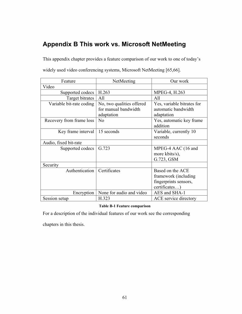
61
Appendix B This work vs. Microsoft NetMeeting
This appendix chapter provides a feature comparison of our work to one of today’s
widely used video conferencing systems, Microsoft NetMeeting [65,66].
Feature NetMeeting Our work Video
Supported codecs H.263 MPEG-4, H.263 Target bitrates All All
Variable bit-rate coding No, two qualities offered for manual bandwidth adaptation
Yes, variable bitrates for automatic bandwidth adaptation
Recovery from frame loss No Yes, automatic key frame addition
Key frame interval 15 seconds Variable, currently 10 seconds
Audio, fixed bit-rate Supported codecs G.723 MPEG-4 AAC (16 and
more kbits/s), G.723, GSM
Security Authentication Certificates Based on the ACE
framework (including fingerprints sensors, certificates…)
Encryption None for audio and video AES and SHA-1 Session setup H.323 ACE service directory
Table B-1 Feature comparison
For a description of the individual features of our work see the corresponding
chapters in this thesis.

62
Appendix C Binominal congestion control analysis
In this appendix chapter we want to give a deeper insight into the reaction of the
congestion control scheme we use. For the work presented in thesis, we combined the
binominal SQRT algorithm with RTCP feedback to compute appropriate transmission
rates (see chapter 4).
The two graphs below show how the algorithm reacts to congestion and probes for
bandwidth availability. The graph (Figure C-1, left) nicely shows that upon
congestion the bandwidth decrease is not by half as traditional TCP, so resulting in
less oscillation. Probing for available bandwidth (Figure C-1, right) results in SQRT
function shaped graph, the steps are smaller than they would be for TCP.
0
10000
20000
30000
40000
50000
60000
70000
020
040
060
080
010
0012
00
time (ms)
bit-
rate
(bit/
s) bit-rate
0
10000
20000
30000
40000
50000
60000
70000
80000
040
080
012
0016
0020
0024
00
time (ms)
bit-
rate
(bit/
s)
bit-rate
Figure C-1 Left: bit-rate decrease, right: bit-rate increase
For these two tests, we used a round trip time (rtt) of 200ms and a frame rate of 30
frames per second. The decrease figure shows, how the stream reacts if per received
report one frame is reported lost. In this test, the reports are sent every 200ms. The

63
increase figure shows the sender probing for bandwidth every 200ms; this test
assumes that no packets are reported lost.
The next diagram (Figure C-2) shows how a 60000 bit/s stream reacts when
congestion reduces the available bandwidth to 30000 bit/s. In this test we are again
using a round trip time of 200ms, 30 frames per second and assume receiver reports
every 200ms.
0
10000
20000
30000
40000
50000
60000
70000
0 400 800 1200 1600 2000 2400 2800 3200 3600 4000 4400 4800
time (ms)
bit-r
ate
(bit/
s)
200msreport interval:
Figure C-2 Bit-rate adaptation for a 200ms report interval
For this test all packets exciding 30000 bit/s were lost and than reported lost by the
next receiver report. For each lost packet the bit-rate is reduced once according to the
SQRT formula (Formula 4-4) introduced in chapter 4.
Since the intervals between reports can differ, we conducted the same test for
different intervals (200ms, 600ms, and 800ms). Our tests suggest that values up to

64
600ms offer a quite good congestion adaptation, while 800ms results in a too extreme
bit-rate oscillation, although it offers a certain degree of adaptation.
0
10000
20000
30000
40000
50000
60000
70000
040
080
012
0016
0020
0024
0028
0032
0036
0040
0044
0048
00
time (ms)
bit-r
ate
(bit/
s)
200ms600ms800ms
report interval:
Figure C-3 Bit-rate adaptation for 200ms, 600ms and 800ms report intervals
For a round trip time of 100ms the result would be the same kind of graph, just with a
different time axis. All time values would need to be divided by two, also the report
intervals need to be divided by two. This means that for a round trip time of 100ms
the graph would represent to report intervals of 100ms, 300ms and 400ms. So it can
be stated that for example a reporting interval of 400ms would result in a better bit-
rate adaptation for a connection with a round trip time of 200ms than with a round
trip time of 100ms. A connection with a higher round trip time usually consists of
more hops and so has a higher change of congestion and data loss. Based on this fact,
we can consider the better adaptation at higher round trip times as appropriate, since

65
the higher change of packet loss of such a connection requires a more accurate
adaptation to reduce the probability of packet loss.

66
Lists
List of Figures
Figure 1-1 Basic block diagram of a video conference system .................................... 3
Figure 2-1: RTP architecture ........................................................................................ 6
Figure 3-1 Dependencies between frames of a MPEG-4 bitstream............................ 12
Figure 3-2 typical video conference situation............................................................. 14
Figure 3-3: Video quality depends on frame loss rate ................................................ 16
Figure 3-4 the effects of frame loss on the frame rate with a certain PSNR, figure
taken from [16] ................................................................................................... 18
Figure 3-5 Instant RTCP feedback packet (figure taken from [13])........................... 21
Figure 4-1: Window size of SQRT and AIMD (TCP) congestion control ................. 30
Figure 5-1: Additional encryption layer ..................................................................... 35
Figure 5-2: Encrypted RTP / RTCP packet ................................................................ 36
Figure 6-1: JMF API architecture ............................................................................... 39
Figure 6-2: Processing media with the JMF ............................................................... 39
Figure 6-3 System block diagram............................................................................... 41
Figure 6-4: Codec test [59] at 48 kbps stereo ............................................................. 46
Figure 6-5: Low impact of packet loss due to good mapping..................................... 49
Figure 6-6: High impact of packet loss due to inappropriate mapping....................... 49
67
Figure 7-1 Image degradation after a lost key frame Test setup: The round trip time is
200ms, 30 frames per second, recovery takes about 360 ms. Between frame 3
and 4 an intra-frame was lost, the frame 16 is the recovery intra-frame ............ 53
Figure 7-2 Left: Window size of the reaction of a SQRT flow to an impulse; Right:
Reaction of a TCP flow to an impulse (both figures are taken from [42]) ......... 56
Figure C-1 Left: bit-rate decrease, right: bit-rate increase.......................................... 62
Figure C-2 Bit-rate adaptation for a 200ms report interval ........................................ 63
Figure C-3 Bit-rate adaptation for 200ms, 600ms and 800ms report intervals .......... 64
List of Tables
Table 3-1 frame size for different frame types and bit-rates ...................................... 13
Table 6-1: Hardware requirements for MPEG-4 AVC real-time coding; the AVC
layer is inappropriate for simultaneous real-time encoding and decoding with
today’s hardware................................................................................................. 45
Table 7-1 Adaptive intra-frame addition test setup .................................................... 54
Table 7-2 Test 1: Sample pictures of the adaptive intra-frame addition test (low
motion, 60kbps) .................................................................................................. 55
Table 7-3 Test 2: Sample pictures of the adaptive intra-frame addition test (high
motion, 300 kbps) ............................................................................................... 55
Table 7-4: Overhead of encryption and hashing......................................................... 57
Table B-1 Feature comparison.................................................................................... 61

68
List of Formulas
Formula 3-1: Root Mean Squared Error (RMSE)....................................................... 17
Formula 3-2: Peak Signal Noise Ratio (PSNR).......................................................... 17
Formula 4-1: Binominal congestion control ............................................................... 28
Formula 4-2: Round trip time (RTT) .......................................................................... 31
Formula 4-3: Window size.......................................................................................... 31
Formula 4-4: Binominal rate control .......................................................................... 32

69
Bibliography [1] M. Salomoni, M. Bonfigle, “A Software Audio Terminal for Interactive Communications in Web-Based Educational Environments over the Internet”, 1999, http://www.cineca.it/~nume03/Papers/IECON99/iecon2.htm [2] H. Schulzrinne, S. Casner, R. Frederick, V. Jacobson, “RTP: A Transport Protocol for Real-Time Applications”, IETF January 1996, RFC 1889 [3] H. Schulzrinne, “RTP Profile for Audio and Video Conferences with Minimal Control”, IETF January 1996, RFC 1890 [4] Moving Picture Experts Group (MPEG), ISO / IEC WG 11, 1998, http://www.chiariglione.org/mpeg/index.htm [5] “Video Codec for audiovisual services at p x 64 kbits/s, ITU-T Recommendation H.261”, Geneva 1990 [6] “Video Coding for narrow telecommunication channels at < 64 kbits/s”, ITU-T Recommendation H.263, 1996 [7] “ISO/IEC 11172”, Part 1 to 5, 1993 to 1998 [8] “ISO/IEC 13818”, Part 1 to 10, 1996 to 2000 [9] “ISO/IEC 14496”, Part 1 to 10, 2000 to 2003 [10] F. Pereira, T. Ebrahimi, “The MPEG-4 Book”, Prentice Hall PTR, Upper Saddle River, NJ, 2002 [11] “The MPEG Audio Web Page“, http://www.tnt.uni-hannover.de/project/mpeg/audio/, 2003 [12] Y. Kikuchi, T. Nomura, S. Fukunaga, Y. Matsui, H. Kimata, “RTP Payload Format for MPEG-4 Audio/Visual Streams”, IETF, November 2000, RFC 3016 [13]J. Ott, S. Wenger, N. Sato, C. Burmeister, J. Rey, “Extended RTP Profile for RTCP-based Feedback (RTP/AVPF)”, IETF, June 2003, draft-ietf-avt-rtcp-feedback-07 [14] “ISO/IEC 14496”, Part 10, 2002, also called: “MPEG-4 AVC” [15] “ISO/IEC 14496”, Part 3, Layer 3, also called: “MPEG-4 HE AAC” [16] N. G. Feamster, “Adaptive Delivery of Real-Time Streaming Video”, Master-Thesis at MIT, 2001 [17] C. Burmeister, R. Hakenberg, J.Rey, A. Miyazaki, K. Hata, “Multiple selective retransmissions in RTP”, 11th International Packet Video Workshop, Kyongju, Korea, May 2001 [18] A. Miyazaki et al., “RTP Payload Format to enable Multiple Selective Retransmissions“, IETF, November 2000, http://www.ietf.org/internet-drafts/draft-ietf-avt-rtp-selret-00.txt [19] K. Yano, M. Podolsky, S. McCanne, “RTP Profile for RTCP-based Retransmission Request for Unicast sessions“, IETF, July 2000, http://www.ietf.org/internet-drafts/draft-ietf-avt-rtprx-00.txt
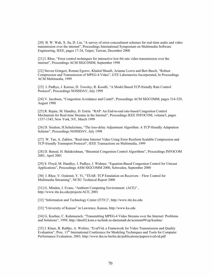
70
[20] B. W. Wah, X. Su, D. Lin, “A survey of error-concealment schemes for real-time audio and video transmission over the internet”, Proceedings International Symposium on Multimedia Software Engineering, IEEE, pages 17-24, Taipei, Taiwan, December 2000 [21] I. Rhee, “Error control techniques for interactive low-bit rate video transmission over the internet”, Proceedings ACM SIGCOMM, September 1998 [22] Steven Gringeri, Roman Egorov, Khaled Shuaib, Arianne Lewis and Bert Basch, “Robust Compression and Transmission of MPEG-4 Video”, GTE Laboratories Incorporated, In Proceedings ACM Multimedia, 1999 [23] J. Padhye, J. Kurose, D. Towsley, R. Koodli, “A Model Based TCP-friendly Rate Control Protocol”, Proceedings NOSSDAV, July 1999 [24] V. Jacobsen, “Congestion Avoidance and Contrl“, Proceedings ACM SIGCOMM, pages 314-329, August 1988 [25] R. Rajaie, M. Handley, D. Estrin. “RAP: An End-to-end rate-based Congestion Control Mechanism for Real-time Streams in the Internet”, Proceedings IEEE INFOCOM, volume3, pages 1337-1345, New York, NY, March 1999 [26] D. Sisalem, H.Schulzrinne, “The loss-delay Adjustment Algorithm: A TCP-friendly Adaptation Scheme”, Proceedings NOSSDAV, July 1998 [27] W. Tan, A. Zakhor, “Real-time Internet Video Using Error Resilient Scalable Compression and TCP-friendly Trannsport Protocol“, IEEE Transactions on Multimedia, 1999 [28] D. Bansal, H. Balakrishnan, “Binomial Congestion Control Algorithms”, Proceedings INFOCOM 2001, April 2001 [29] S. Floyd, M. Handley, J. Padhye, J. Widmer, “Equation-Based Congestion Control for Unicast Applications”, Proceedings ASM SIGCOMM 2000, Schweden, September 2000 [30] I. Rhee, V. Ozdemit, Y. Yi, “TEAR: TCP Emulation on Receivers – Flow Control for Multimedia Streaming”, NCSU Technical Report 2000 [31] G. Minden, J. Evans, “Ambient Computing Environment (ACE)” , http://www.ittc.ku.edu/projects/ACE, 2001 [32] “Information and Technology Center (ITTC)”, http://www.ittc.ku.edu [33] “University of Kansas” in Lawrence, Kansas, http://www.ku.edu [34] G. Kuehne, C. Kuhmuench, “Transmitting MPEG-4 Video Streams over the Internet: Problems and Solutions”, 1999, http://dmz02.kom.e-technik.tu-darmstadt.de/acmmm99/ep/kuehne/ [35] J. Klaue, B. Rathke, A. Wolitsz, “EvalVid, a Framework for Video Transmission and Quality Evaluation”, Proc. 13th International Conference for Modeling Techniques and Tools for Computer Performance Evaluation, 2003, http://www.tkn.tu-berlin.de/publications/papers/evalvid.pdf
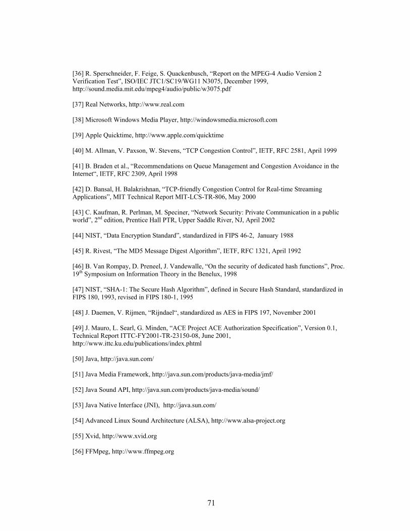
71
[36] R. Sperschneider, F. Feige, S. Quackenbusch, “Report on the MPEG-4 Audio Version 2 Verification Test”, ISO/IEC JTC1/SC19/WG11 N3075, December 1999, http://sound.media.mit.edu/mpeg4/audio/public/w3075.pdf [37] Real Networks, http://www.real.com [38] Microsoft Windows Media Player, http://windowsmedia.microsoft.com [39] Apple Quicktime, http://www.apple.com/quicktime [40] M. Allman, V. Paxson, W. Stevens, “TCP Congestion Control”, IETF, RFC 2581, April 1999 [41] B. Braden et al., “Recommendations on Queue Management and Congestion Avoidance in the Internet“, IETF, RFC 2309, April 1998 [42] D. Bansal, H. Balakrishnan, “TCP-friendly Congestion Control for Real-time Streaming Applications”, MIT Technical Report MIT-LCS-TR-806, May 2000 [43] C. Kaufman, R. Perlman, M. Speciner, “Network Security: Private Communication in a public world”, 2nd edition, Prentice Hall PTR, Upper Saddle River, NJ, April 2002 [44] NIST, “Data Encryption Standard”, standardized in FIPS 46-2, January 1988 [45] R. Rivest, “The MD5 Message Digest Algorithm”, IETF, RFC 1321, April 1992 [46] B. Van Rompay, D. Preneel, J. Vandewalle, “On the security of dedicated hash functions”, Proc. 19th Symposium on Information Theory in the Benelux, 1998 [47] NIST, “SHA-1: The Secure Hash Algorithm”, defined in Secure Hash Standard, standardized in FIPS 180, 1993, revised in FIPS 180-1, 1995 [48] J. Daemen, V. Rijmen, “Rijndael“, standardized as AES in FIPS 197, November 2001 [49] J. Mauro, L. Searl, G. Minden, “ACE Project ACE Authorization Specification”, Version 0.1, Technical Report ITTC-FY2001-TR-23150-08, June 2001, http://www.ittc.ku.edu/publications/index.phtml [50] Java, http://java.sun.com/ [51] Java Media Framework, http://java.sun.com/products/java-media/jmf/ [52] Java Sound API, http://java.sun.com/products/java-media/sound/ [53] Java Native Interface (JNI), http://java.sun.com/ [54] Advanced Linux Sound Architecture (ALSA), http://www.alsa-project.org [55] Xvid, http://www.xvid.org [56] FFMpeg, http://www.ffmpeg.org

72
[57] Envivio Inc., “H.264 – The New Video Codec“, 2002, http://www.envivio.com/images/products/h264FactSheet.pdf [58] Audiocoding.com, http://www.audiocoding.com [59] D. Meares, K. Watanabe, E. Scheirer, “Report on the MPEG-2 AAC Stereo Verification Tests”, ISO/IEC JTC1/SC29/WG11 N2006, February 1998 [60]“Dual rate speech coder for multimedia telecommunication transmitting at 5.3 and 6.3 kbit/s”, ITU-T Recommendation G.723.1, 1996 [61] “GSM 06.10 RPELTP”, prI-ETS 300 036, ETSI, 1990 [62] MPEG4Tools are part of MPEG4IP, http://www.mpeg4ip.net [63] IBM Toolkit for MPEG-4, http://www.alphaworks.ibm.com/tech/tk4mpeg4 [64] MPlayer, http://www.mplayerhq.hu/homepage/ [65] Microsoft NetMeeting, Version 3.01, January 2002 http://www.microsoft.com/windows/netmeeting/default.asp [66] Microsoft NetMeeting Resource Kit, December 1999, http://www.microsoft.com/windows/NetMeeting/Corp/reskit/About/default.asp