mpc8379e chip errata - nxp...
TRANSCRIPT
This document details all known silicon errata for the MPC8379E PowerQUICC II Pro family of integrated hostprocessors. This document also applies to the MPC8378E and MPC8377E, as noted in each erratum description.The following table provides a revision history for this document.
Table 1. Revision history
Revision Date Significant changes
7 06/2014 Added eTSEC A-007207
Modified eTSEC69
Renamed eTSEC-A002 to A-006502
6 09/2013 Added the following errata:• SATA A-005255, A-005636, and A-006187• USB A-003829 and A-003845
Modified the following errata:• eSDHC5• IEEE1588-A001
Updated the Silicon Revision from 2.0 to 2.1 in Table 3, "Summary of Silicon Errata andApplicable Revision"
5 11/2012 • Renamed USB38 to USB erratum A-003817• Added eSDHC errata eSDHC23, A-004577, A-005055 A-005286 and A-005287; SATA
A-005035; and USB erratum A-003837.• Modified eSDHC16 workaround.
4 08/2011 • Added CPU-A022, USB-A005, USB-A007, eTSEC79• Updated impact for SEC-A001• Updated work around for PCI20
3 12/2010 • Added PCIe-A002, SEC-A001, USB-A003• Updated eTSEC-A002, IEEE1588-A001, PEX7, SATA2, SATA-A002, USB-A002• Updated work around for eSDHC19, USB32
2 05/2010 • Updated workaround for eTSEC20, eTSEC76• Updated wording for eLBC2, eLBC5, eTSEC13, eTSEC16, SEC14• Added eLBC-A001, eSDHC-A001, eTSEC78, eTSEC-A001, eTSEC-A002, IEEE1588-
A001, PEX9, SATA-A002, USB-A001, USB-A002
1 07/2009 • Added General16, IEEE_1588_21, CPU6, eSDHC17-eSDHC20, USB32-USB38,eTSEC76-eTSEC77
Table continues on the next page...
Freescale Semiconductor MPC8379ECE
Chip Errata Rev 7, 06/2014
MPC8379E Chip Errata
© 2014 Freescale Semiconductor, Inc.
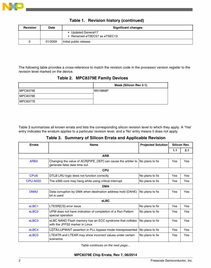
Table 1. Revision history (continued)
Revision Date Significant changes
• Updated General17• Renamed eTSEC57 as eTSEC13.
0 01/2009 Initial public release.
The following table provides a cross-reference to match the revision code in the processor version register to therevision level marked on the device.
Table 2. MPC8379E Family Devices
Mask (Silicon Rev 2.1)
MPC8379E W01M68P
MPC8378E
MPC8377E
Table 3 summarizes all known errata and lists the corresponding silicon revision level to which they apply. A 'Yes'entry indicates the erratum applies to a particular revision level, and a 'No' entry means it does not apply.
Table 3. Summary of Silicon Errata and Applicable Revision
Errata Name Projected Solution Silicon Rev.
1.1 2.1
ARB
ARB3 Changing the value of ACR[PIPE_DEP] can cause the arbiter togenerate false data time out
No plans to fix Yes Yes
CPU
CPU6 DTLB LRU logic does not function correctly No plans to fix Yes Yes
CPU-A022 The e300 core may hang while using critical interrupt No plans to fix Yes Yes
DMA
DMA2 Data corruption by DMA when destination address hold (DAHE)bit is used
No plans to fix Yes Yes
eLBC
eLBC1 LTESR[CS] error issue No plans to fix Yes Yes
eLBC2 UPM does not have indication of completion of a Run Patternspecial operation
No plans to fix Yes Yes
eLBC3 eLBC NAND Flash memory has an ECC syndrome that collideswith the JFFS2 marker in Linux
No plans to fix Yes Yes
eLBC4 LGTA/LUPWAIT assertion in PLL-bypass mode misrepresented No plans to fix Yes Yes
eLBC5 LTEATR and LTEAR may show incorrect values under certainscenarios
No plans to fix Yes Yes
Table continues on the next page...
MPC8379E Chip Errata, Rev 7, 06/2014
2 Freescale Semiconductor, Inc.
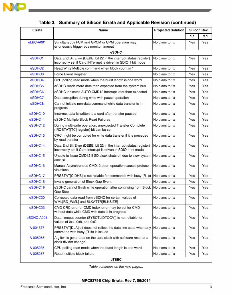
Table 3. Summary of Silicon Errata and Applicable Revision (continued)
Errata Name Projected Solution Silicon Rev.
1.1 2.1
eLBC-A001 Simultaneous FCM and GPCM or UPM operation mayerroneously trigger bus monitor timeout
No plans to fix Yes Yes
eSDHC
eSDHC1 Data End Bit Error (DEBE, bit 22 in the interrupt status register)incorrectly set if Card INTerrupt is driven in SDIO 1 bit mode
No plans to fix Yes Yes
eSDHC2 Read/Write Multiple command when block count is 1 No plans to fix Yes Yes
eSDHC3 Force Event Register No plans to fix Yes Yes
eSDHC4 CPU polling read mode when the burst length is one word No plans to fix Yes Yes
eSDHC5 eSDHC reads more data than expected from the system bus No plans to fix Yes Yes
eSDHC6 eSDHC indicates AUTO CMD12 interrupt later than expected No plans to fix Yes Yes
eSDHC7 Data corruption during write with pause operation No plans to fix Yes Yes
eSDHC8 Cannot initiate non-data command while data transfer is inprogress
No plans to fix Yes Yes
eSDHC10 Incorrect data is written to a card after transfer paused No plans to fix Yes Yes
eSDHC11 eSDHC Multiple Block Read Failures No plans to fix Yes Yes
eSDHC12 During multi-write operation, unexpected Transfer Complete(IRQSTAT[TC] register) bit can be set
No plans to fix Yes Yes
eSDHC13 CRC might be corrupted for write data transfer if it is precededby read transfer
No plans to fix Yes Yes
eSDHC14 Data End Bit Error (DEBE, bit 22 in the interrupt status register)incorrectly set if Card Interrupt is driven in SDIO 4-bit mode
No plans to fix Yes Yes
eSDHC15 Unable to issue CMD12 if SD clock shuts off due to slow systemaccess
No plans to fix Yes Yes
eSDHC16 Manual Asynchronous CMD12 abort operation causes protocolviolations
No plans to fix Yes Yes
eSDHC17 PRSSTAT[CIDHB] is not reliable for commands with busy (R1b) No plans to fix Yes Yes
eSDHC18 Invalid generation of Block Gap Event No plans to fix Yes Yes
eSDHC19 eSDHC cannot finish write operation after continuing from BlockGap Stop
No plans to fix Yes Yes
eSDHC20 Corrupted data read from eSDHC for certain values ofWML[RD_WML] and BLKATTR[BLKSIZE]
No plans to fix Yes Yes
eSDHC23 CMD CRC error or CMD index error may be set for CMDwithout data while CMD with data is in progress
No plans to fix Yes Yes
eSDHC-A001 Data timeout counter (SYSCTL[DTOCV]) is not reliable forvalues of 0x4, 0x8, and 0xC
No plans to fix Yes Yes
A-004577 PRSSTAT[DLA] bit does not reflect the data line state when anycommand with busy (R1b) is issued
No plans to fix Yes Yes
A-005055 A glitch is generated on the card clock with software reset or aclock divider change
No plans to fix Yes Yes
A-005286 CPU polling read mode when the burst length is one word No plans to fix Yes Yes
A-005287 Read multiple block failure No plans to fix Yes Yes
eTSEC
Table continues on the next page...
MPC8379E Chip Errata, Rev 7, 06/2014
Freescale Semiconductor, Inc. 3
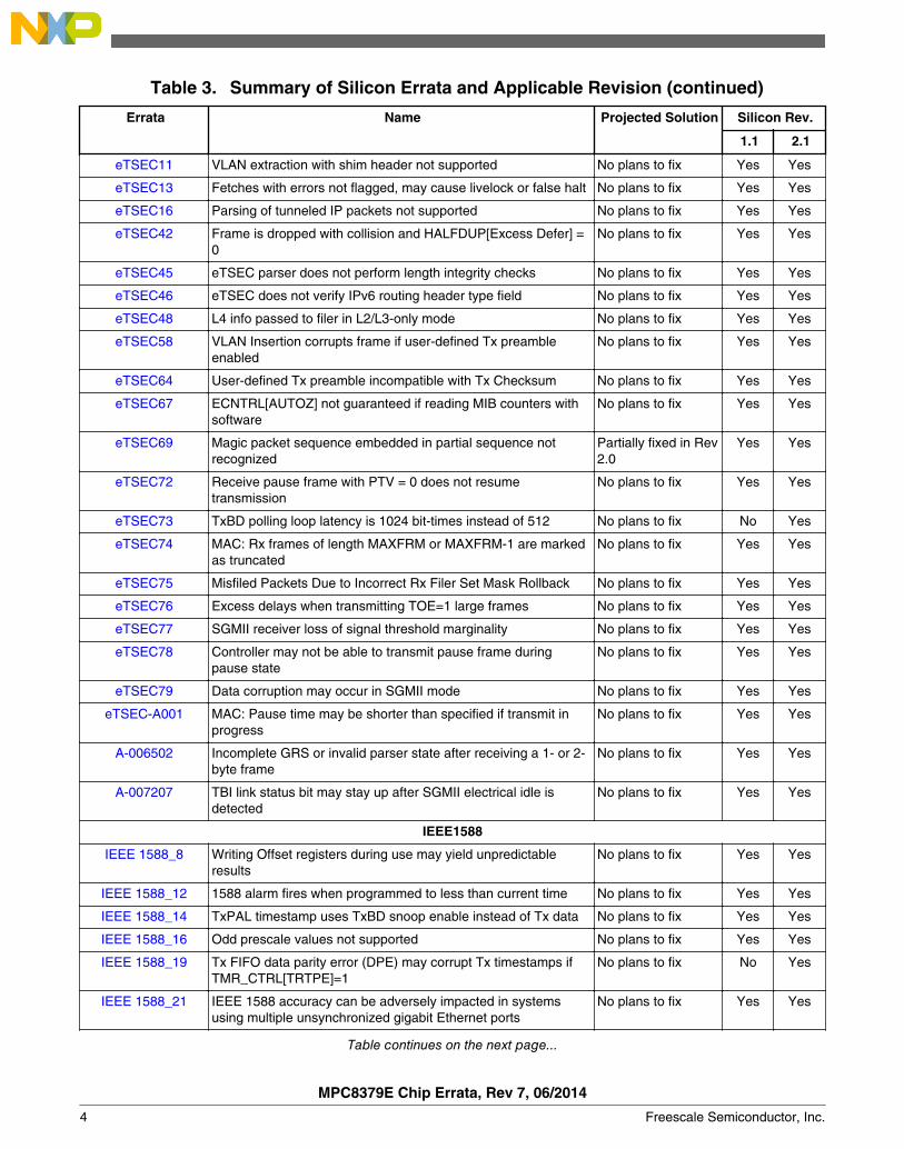
Table 3. Summary of Silicon Errata and Applicable Revision (continued)
Errata Name Projected Solution Silicon Rev.
1.1 2.1
eTSEC11 VLAN extraction with shim header not supported No plans to fix Yes Yes
eTSEC13 Fetches with errors not flagged, may cause livelock or false halt No plans to fix Yes Yes
eTSEC16 Parsing of tunneled IP packets not supported No plans to fix Yes Yes
eTSEC42 Frame is dropped with collision and HALFDUP[Excess Defer] =0
No plans to fix Yes Yes
eTSEC45 eTSEC parser does not perform length integrity checks No plans to fix Yes Yes
eTSEC46 eTSEC does not verify IPv6 routing header type field No plans to fix Yes Yes
eTSEC48 L4 info passed to filer in L2/L3-only mode No plans to fix Yes Yes
eTSEC58 VLAN Insertion corrupts frame if user-defined Tx preambleenabled
No plans to fix Yes Yes
eTSEC64 User-defined Tx preamble incompatible with Tx Checksum No plans to fix Yes Yes
eTSEC67 ECNTRL[AUTOZ] not guaranteed if reading MIB counters withsoftware
No plans to fix Yes Yes
eTSEC69 Magic packet sequence embedded in partial sequence notrecognized
Partially fixed in Rev2.0
Yes Yes
eTSEC72 Receive pause frame with PTV = 0 does not resumetransmission
No plans to fix Yes Yes
eTSEC73 TxBD polling loop latency is 1024 bit-times instead of 512 No plans to fix No Yes
eTSEC74 MAC: Rx frames of length MAXFRM or MAXFRM-1 are markedas truncated
No plans to fix Yes Yes
eTSEC75 Misfiled Packets Due to Incorrect Rx Filer Set Mask Rollback No plans to fix Yes Yes
eTSEC76 Excess delays when transmitting TOE=1 large frames No plans to fix Yes Yes
eTSEC77 SGMII receiver loss of signal threshold marginality No plans to fix Yes Yes
eTSEC78 Controller may not be able to transmit pause frame duringpause state
No plans to fix Yes Yes
eTSEC79 Data corruption may occur in SGMII mode No plans to fix Yes Yes
eTSEC-A001 MAC: Pause time may be shorter than specified if transmit inprogress
No plans to fix Yes Yes
A-006502 Incomplete GRS or invalid parser state after receiving a 1- or 2-byte frame
No plans to fix Yes Yes
A-007207 TBI link status bit may stay up after SGMII electrical idle isdetected
No plans to fix Yes Yes
IEEE1588
IEEE 1588_8 Writing Offset registers during use may yield unpredictableresults
No plans to fix Yes Yes
IEEE 1588_12 1588 alarm fires when programmed to less than current time No plans to fix Yes Yes
IEEE 1588_14 TxPAL timestamp uses TxBD snoop enable instead of Tx data No plans to fix Yes Yes
IEEE 1588_16 Odd prescale values not supported No plans to fix Yes Yes
IEEE 1588_19 Tx FIFO data parity error (DPE) may corrupt Tx timestamps ifTMR_CTRL[TRTPE]=1
No plans to fix No Yes
IEEE 1588_21 IEEE 1588 accuracy can be adversely impacted in systemsusing multiple unsynchronized gigabit Ethernet ports
No plans to fix Yes Yes
Table continues on the next page...
MPC8379E Chip Errata, Rev 7, 06/2014
4 Freescale Semiconductor, Inc.

Table 3. Summary of Silicon Errata and Applicable Revision (continued)
Errata Name Projected Solution Silicon Rev.
1.1 2.1
IEEE1588-A001 Incorrect received timestamp or dropped/data corruption packetwhen 1588 time-stamping is enabled
No plans to fix Yes Yes
General
General16 Enabling I2C could cause I2C bus freeze when other I2C devicescommunicate
No plans to fix Yes Yes
General17 DUART: Break detection triggered multiple times for a singlebreak assertion
No plans to fix Yes Yes
General18 Machine Model (MM) Electrostatic Discharge (ESD) criteria notmet by certain SerDes pins
No plans to fix Yes Yes
JTAG
JTAG6 Boundary scan test on SerDes pins unreliable No plans to fix Yes Yes
PCI
PCI15 Assertion of STOP by a target device on the last beat of a PCImemory write transaction can cause a hang
No plans to fix Yes Yes
PCI19 Dual-address cycle inbound write accesses can cause datacorruption
No plans to fix Yes Yes
PCI20 PCI controller may hang when returning from "PCI pins low"state
No plans to fix Yes Yes
PCIe
PEX1 No support of PCI Express completions with BCM bit set (PCIXbridge interface)
No plans to fix Yes Yes
PEX2 DMA Interrupt descriptor race condition (IDRC) No plans to fix Yes Yes
PEX7 Recovery from hot reset or link down No plans to fix Yes Yes
PEX9 Excess correctable errors in receiving DLLPs and TLPs on x2link
No plans to fix Yes Yes
PCIe-A002 PCI Express Packets may be transmitted with excess data onx1 link
No plans to fix Yes Yes
RESET
RESET3 External Soft reset functionality is not functional No plans to fix Yes Yes
SATA
SATA2 Reads of one sector from hard disk may return less data thanrequested
No plans to fix Yes Yes
SATA3 SATA controller hangs when handling data integrity errors No plans to fix Yes Yes
SATA9 Fails the SATA InterOperability Sinusoidal Jitter test No plans to fix Yes Yes
SATA12 SATA: DMAT handling in SATA not as expected No plans to fix Yes Yes
SATA13 BIST-L mode is not enabled by BIST-L FIS No plans to fix Yes Yes
SATA-A002 ATAPI commands may fail to complete No plans to fix Yes Yes
A-005035 Possible data loss if PRD[DBA] or PRD[DWC] is not at least 16-byte aligned
No plans to fix Yes Yes
A-005255 Failure to Detect Single SYNC Primitive No plans to fix Yes Yes
A-005636 Auto-activate feature enabled in DMA setup command causestimeout
No plans to fix Yes Yes
Table continues on the next page...
MPC8379E Chip Errata, Rev 7, 06/2014
Freescale Semiconductor, Inc. 5
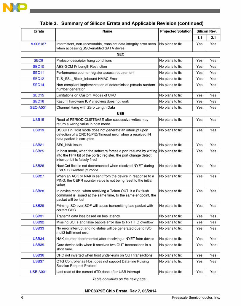
Table 3. Summary of Silicon Errata and Applicable Revision (continued)
Errata Name Projected Solution Silicon Rev.
1.1 2.1
A-006187 Intermittent, non-recoverable, transient data integrity error seenwhen accessing SSC-enabled SATA drives
No plans to fix Yes Yes
SEC
SEC9 Protocol descriptor hang conditions No plans to fix Yes Yes
SEC10 AES-GCM IV Length Restriction No plans to fix Yes Yes
SEC11 Performance counter register access requirement No plans to fix Yes Yes
SEC12 TLS_SSL_Block_Inbound HMAC Error No plans to fix Yes Yes
SEC14 Non-compliant implementation of deterministic pseudo-randomnumber generator
No plans to fix Yes Yes
SEC15 Limitations on Custom Modes of CRC No plans to fix Yes Yes
SEC16 Kasumi hardware ICV checking does not work No plans to fix Yes Yes
SEC-A001 Channel Hang with Zero Length Data No plans to fix Yes Yes
USB
USB15 Read of PERIODICLISTBASE after successive writes mayreturn a wrong value in host mode
No plans to fix Yes Yes
USB19 USBDR in Host mode does not generate an interrupt upondetection of a CRC16/PID/Timeout error when a received INdata packet is corrupted
No plans to fix Yes Yes
USB21 SE0_NAK issue No plans to fix Yes Yes
USB25 In host mode, when the software forces a port resume by writinginto the FPR bit of the portsc register, the port change detectinterrupt bit is falsely fired
No plans to fix Yes Yes
USB26 NackCnt field is not decremented when received NYET duringFS/LS Bulk/Interrupt mode
No plans to fix Yes Yes
USB27 When an ACK or NAK is sent from the device in response to aPING, the CERR counter value is not being reset to the initialvalue
No plans to fix Yes Yes
USB28 In device mode, when receiving a Token OUT, if a Rx flushcommand is issued at the same time, to the same endpoint, thepacket will be lost
No plans to fix Yes Yes
USB29 Priming ISO over SOF will cause transmitting bad packet withcorrect CRC
No plans to fix Yes Yes
USB31 Transmit data loss based on bus latency No plans to fix Yes Yes
USB32 Missing SOFs and false babble error due to Rx FIFO overflow No plans to fix Yes Yes
USB33 No error interrupt and no status will be generated due to ISOmult3 fulfillment error
No plans to fix Yes Yes
USB34 NAK counter decremented after receiving a NYET from device No plans to fix Yes Yes
USB35 Core device fails when it receives two OUT transactions in ashort time
No plans to fix Yes Yes
USB36 CRC not inverted when host under-runs on OUT transactions No plans to fix Yes Yes
USB37 OTG Controller as Host does not support Data-line PulsingSession Request Protocol
No plans to fix Yes Yes
USB-A001 Last read of the current dTD done after USB interrupt No plans to fix Yes Yes
Table continues on the next page...
MPC8379E Chip Errata, Rev 7, 06/2014
6 Freescale Semiconductor, Inc.
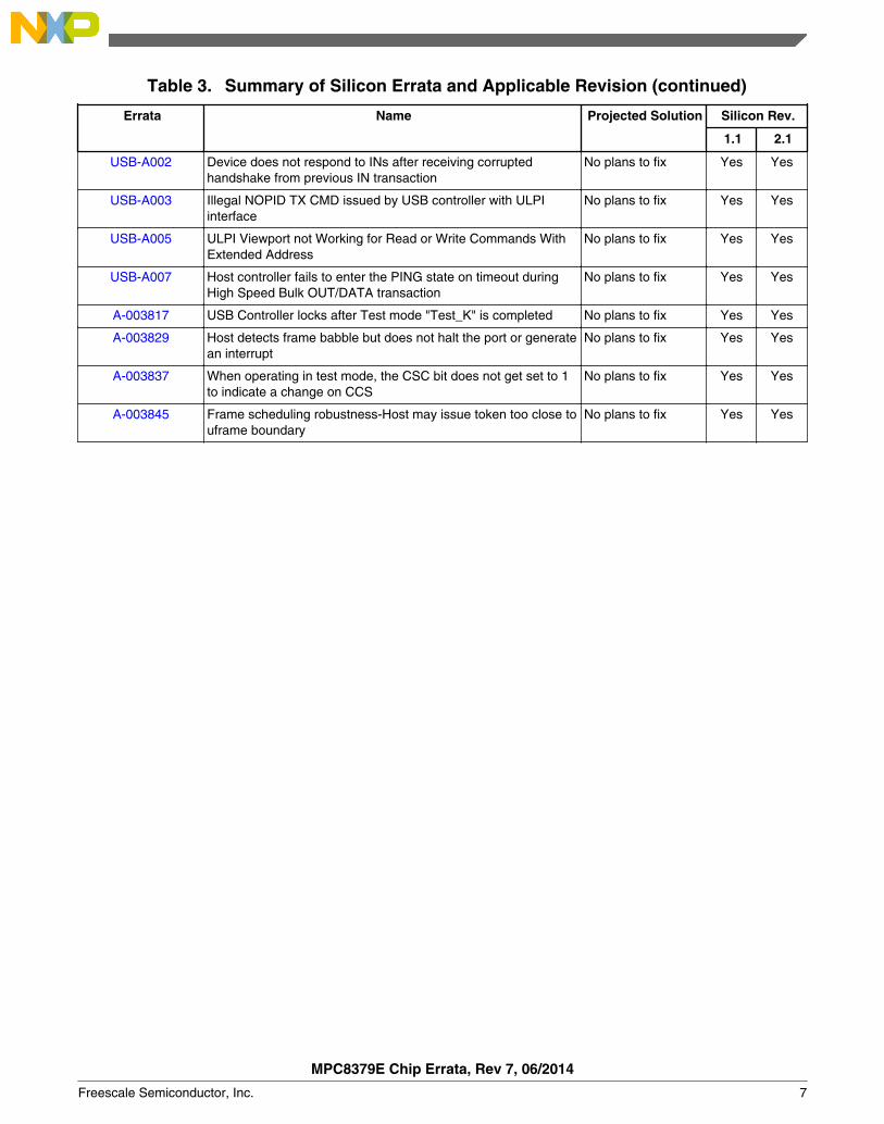
Table 3. Summary of Silicon Errata and Applicable Revision (continued)
Errata Name Projected Solution Silicon Rev.
1.1 2.1
USB-A002 Device does not respond to INs after receiving corruptedhandshake from previous IN transaction
No plans to fix Yes Yes
USB-A003 Illegal NOPID TX CMD issued by USB controller with ULPIinterface
No plans to fix Yes Yes
USB-A005 ULPI Viewport not Working for Read or Write Commands WithExtended Address
No plans to fix Yes Yes
USB-A007 Host controller fails to enter the PING state on timeout duringHigh Speed Bulk OUT/DATA transaction
No plans to fix Yes Yes
A-003817 USB Controller locks after Test mode "Test_K" is completed No plans to fix Yes Yes
A-003829 Host detects frame babble but does not halt the port or generatean interrupt
No plans to fix Yes Yes
A-003837 When operating in test mode, the CSC bit does not get set to 1to indicate a change on CCS
No plans to fix Yes Yes
A-003845 Frame scheduling robustness-Host may issue token too close touframe boundary
No plans to fix Yes Yes
MPC8379E Chip Errata, Rev 7, 06/2014
Freescale Semiconductor, Inc. 7

ARB3: Changing the value of ACR[PIPE_DEP] can cause the arbiter to generate falsedata time out
Description: Devices: MPC8379E, MPC8378E, MPC8377E
If the pipeline depth is changed to any value other than zero by writing to ACR[PIPE_DEP],and the next transaction is acknowledged or retried at the same cycle that the actual pipedepth value change is registered in the arbiter logic, the arbiter internal logic will be broken.
Impact: The arbiter generates a false data time out.
Workaround: If the system is configured by the e300 CPU:
• Make sure no other masters are active when pipe depth is configured.• Add a loop of 100 NOP instructions following the store to ACR. In order to avoid an
instruction fetch after the ACR write, make sure the instruction cache is on and that theACR write and the loop of 100 NOPs are in the same cache line.This will ensure that noinstruction is fetched after the ACR write and that, therefore, CSB is idle while the pipedepth is being updated.
For PCI agent mode, use an external PCI host to configure the system. Hold the e300 in coredisable mode by setting the CORE_DIS bit in RCWH. Set ACR[PIPE_DEP] to the desiredvalue and then wait for at least 1 μs before issuing further transactions to the device. At thispoint the e300 core can be enabled to fetch its boot code by clearing ACR[CORE_DIS].
If possible, use the I2C boot sequencer to configure initial settings of the system, includingACR[PIPE_DEP].
Fix plan: No plans to fix
MPC8379E Chip Errata, Rev 7, 06/2014
8 Freescale Semiconductor, Inc.
CPU6: DTLB LRU logic does not function correctly
Description: Devices: MPC8379E, MPC8378E, MPC8377E
The DTLB is implemented as 2-way set associative with 32 entries per way. EA[15:19] is usedto determine which one of the 32 entries of both ways. When a DTLB miss occurs, normallythe CPU provides information (through SRR1 bit 14, DTLB replacement way) to indicate whichof the two ways the software (DTLB exception handler or the software table walk routine)should use to bring in the new page. Presumably, the CPU provides the information, throughSRR1 bit 14, based on the LRU (least recently used) algorithm. However, because of this bug,this is not the case.
In fact, for any given EA[15:19], when a DTLB miss occurs, SRR1 bit 14 always indicates thatway1 should be used or replaced. (Except if it is the very first DTLB miss after hard reset. Inthis case, SRR1 bit 14 indicates way0 should be used.)
In other words, if the DTLB exception routine follows the SRR1 bit 14's suggestion to do theTLB replacement, it always replaces the one in way1. In addition, whatever has been loaded inway0 is effectively locked and is not replaced.
Impact: Performance degradation due to the reduction of usable DTLB entries.
Workaround: In the software, use one word (32 bits) to keep the record of the DTLB way that is LeastRecently Written (LRW). Use this information to overwrite the SRR1 bit 14 (DTLB replacementway) when a Data Translation Miss exception occurs. Basically, the LRU (least recently used)hardware algorithm is changed to an LRW (least recently written) software algorithm.
For the system that has no secondary storage (such as a hard drive), it is highly recommendedto set the C (Change) bit during the DTLB load exception to optimize the performance.
For a system that has a secondary storage and the OS does a page swap, the OS can choosewhether to set the C bit in the DTLB load exception.
If the C bit is set in the DTLB load exception, it can preempt the subsequent DTLB storeexception to the same page. However, since all the pages are marked as changed, during thepage swap all pages must be written back to the secondary storage regardless of whether theyhave really been changed or not.
If the C bit is not set in the DTLB load exception with the LRW algorithm, a subsequent store tothe same page as the previous load will use a separate entry. Therefore, one page occupiesboth ways. This causes inefficiency for the DTLB allocation but may save time during the pageswap since the page change status is correctly marked.
Fix plan: No plans to fix
MPC8379E Chip Errata, Rev 7, 06/2014
Freescale Semiconductor, Inc. 9
CPU-A022: The e300 core may hang while using critical interrupt
Description: Devices: MPC8379E, MPC8378E, MPC8377E
If BOTH critical interrupt AND normal interrupt types are used in a system, the e300 core mayhang.
Impact: The processor may stop dispatching instructions until a hardware reset(HRESET). Debug toolswill not be able to read any register correctly except program counter IAR which points to alocation in the critical interrupt vector.
Workaround: If both critical interrupt and normal interrupt types are used, then instead of using an rfiinstruction at the end of every exception handler, replace the rfi with the following:
1. Disable critical interrupts by setting MSR[CE] to 0 with a mtspr instruction.2. Copy SRR0 and SRR1 to CSRR0 and CSRR1, respectively.3. Execute an rfci instruction. This enables MSR[CE] and any other bits that the original rfi
would have set including the MSR[EE].
Sample Code:
// Disable MSR[CE] mfmsr r2 lis r3, 0xffffori r3, r3, 0xff7f and r2, r2, r3 sync mtmsr r2 isync// Copy SRR0, SRR1 to CSRR0 and CSRR1 mfspr r2, srr0 mfspr r3, srr1 mtspr csrr0, r2 mtspr csrr1, r3 ...restore GPRs rfci
Fix plan: No plans to fix
MPC8379E Chip Errata, Rev 7, 06/2014
10 Freescale Semiconductor, Inc.

DMA2: Data corruption by DMA when destination address hold (DAHE) bit is used
Description: Devices: MPC8379E, MPC8378E, MPC8377E
There can be corruption of the DMA data under the following conditions:
• DMAMR[DAHE] = 1 (destination address hold)• DMAMR[DAHTS] = 10 (4 bytes) or 11 (8 bytes)• DMA source address is not aligned to the transaction size specified by DAHTS• The source port width is smaller than the destination transaction size or the source port
returns valid read data only in the valid byte lanes
Examples of error condition are as follows:
• DAHTS is 8 bytes and the source port is a 32-bit PCI bus• The source memory space is on the PCI bus and is not prefetchable
Impact: Corrupted data written to the destination peripheral or memory.
Workaround: Use one of the following options:
• Use a source address aligned to the destination transaction size• Do not access any DMA registers while this type of DMA transfer is active
Fix plan: No plans to fix
MPC8379E Chip Errata, Rev 7, 06/2014
Freescale Semiconductor, Inc. 11
eLBC1: LTESR[CS] error issue
Description: Devices: MPC8379E, MPC8378E, MPC8377E
LSOR is used as a special operation by reporting chip select errors in LTESR[CS]. This specialoperation initiates a correct response as expected by the OP field. For example, whenOP = 01, that is, the UPM RAM Array is to be written and LSOR is written, then correct datafrom MDR is written into the UPM RAM word, but this gives a chip select error. This works finewhen JTAG is used as the master but gives a CS error when the core is the master. As analternative, if a dummy write is used instead of a write to LSOR, it does not report aLTESR[CS] error.
Impact: A write to LSOR performs the correct intended operation, but this causes an LTESR[CS] error.So, software will report error if it is monitoring the LTESR register.
Workaround: A dummy transaction can be used as an alternative to writing to LSOR, which performs thesame operation.
Fix plan: No plans to fix
MPC8379E Chip Errata, Rev 7, 06/2014
12 Freescale Semiconductor, Inc.

eLBC2: UPM does not have indication of completion of a Run Pattern special operation
Description: Devices: MPC8379E, MPC8378E, MPC8377E
A UPM or FCM special operation is initiated by writing to MxMR[OP] or FCM[OP] and thentriggering the special operation either through the LSOR register or by performing a dummyaccess to the bank.
The UPM and FCM are expected to have different indications of when the special operation iscompleted. The FCM will see the LTESR[CC] bit set when such a special operation iscompleted. The UPM will see MxMR[MAD] increment when a write to or read from UPM arrayspecial operation completes. However, the UPM does not have any status indication ofcompletion of the run pattern special operation.
The following two scenarios could be affected by this erratum:
1. A UPM Run Pattern special operation is initiated and a second UPM command is issuedbefore the Run Pattern is completed.
If the above scenario occurs the programmed mode registers could be altered accordingto the second operation and cause the current/first operation to encounter errors due tomode changes in the middle of the operation. Note that if the second command issued isa Run Pattern operation and it does not change the mode registers, the first operationshould not encounter errors.
2. A write to LSOR initiates a UPM Run Pattern special operation and then LSOR is writtentoo again, to initiate a second special operation that requires the mode registers tochange while the first Run Pattern operation is in progress.
If the second special operation issued does not change the programming mode of thefirst Run Pattern operation because the operation is either exactly the same as the first orit requires programming of an independent set of registers then the Run Patternoperation should not encounter errors.
The behavior of the eLBC is unpredictable if the Run Pattern special operation mode is alteredbetween initiation of the operation and the relevant memory controller completing theoperation.
Impact: Because of this erratum, when a UPM run pattern special operation is to be followed by anyother UPM command for which the mode registers need to change, the Run Pattern operationmay not be handled properly. Software does not have any means to confirm when the currentrun pattern special operation has completed so that register programming for the nextoperation can be done safely.
Workaround: None
Fix plan: No plans to fix
MPC8379E Chip Errata, Rev 7, 06/2014
Freescale Semiconductor, Inc. 13
eLBC3: eLBC NAND Flash memory has an ECC syndrome that collides with the JFFS2marker in Linux
Description: Devices: MPC8379E, MPC8378E, MPC8377E
The current NAND Flash memory ECC location collides with the JFFS2 marker in Linux. Thereis no industry specification about where the ECC syndrome should be placed.
Impact: Cannot boot from NAND flash if flash includes Linux JFFS2 markers.
Workaround: Disable hardware ECC and use software ECC instead. But hardware ECC is enabled bydefault during 4K boot phase and can only be disabled once boot is over for remaining datatransfers. If the software can handle this, by using hardware ECC for the 4K boot block andsoftware ECC for the rest of the NAND Flash, this workaround would work well.
Fix plan: No plans to fix
MPC8379E Chip Errata, Rev 7, 06/2014
14 Freescale Semiconductor, Inc.
eLBC4: LGTA/LUPWAIT assertion in PLL-bypass mode misrepresented
Description: Devices: MPC8379E, MPC8378E, MPC8377E
In the Local Bus section of the Hardware Specification document, the timing diagram figuresfor PLL-bypass mode show that the LGTA/LUPWAIT signal is latched on the falling edge of theinternal launch/capture clock signal. This is a misrepresentation of the device functionality asLGTA/LUPWAIT is actually latched on the subsequent rising edge of the internal launch/capture clock signal.
Impact: Asserting LGTA/LUPWAIT for only the falling edge of the internal launch/capture clock signalin PLL-bypass mode will result in the local bus controller not registering the LGTA/LUPWAITinput.
Workaround: Asserting the LGTA/LUPWAIT signal for an additional LCLK cycle in PLL-bypass mode willguarantee the local bus controller registering the LGTA/LUPWAIT input correctly.
Fix plan: No plans to fix
MPC8379E Chip Errata, Rev 7, 06/2014
Freescale Semiconductor, Inc. 15

eLBC5: LTEATR and LTEAR may show incorrect values under certain scenarios
Description: Devices: MPC8379E, MPC8378E, MPC8377E
The eLBC IP acks any transaction request when FCM special operation is in progress. In sucha scenario when any one of the errors/events occur (such as Bus Monitor Timeout, WriteProtect, Parity error, Atomic error, FCM command completion, or UPM command completionexcept for the CS error), the registers LTEAR and LTEATR capture the address and attributesof the most recently req-acked transaction instead of the FCM special operation that causederror. Hence indeterministic value may show up in those registers.
Impact: LTEAR and LTEATR cannot be used for debugging in this scenario.
Workaround: None
Fix plan: No plans to fix
MPC8379E Chip Errata, Rev 7, 06/2014
16 Freescale Semiconductor, Inc.
eLBC-A001: Simultaneous FCM and GPCM or UPM operation may erroneously triggerbus monitor timeout
Description: Devices: MPC8379E, MPC8378E, MPC8377E
When the FCM is in the middle of a long transaction, such as NAND erase or write, anothertransaction on the GPCM or UPM triggers the bus monitor to start immediately for the GPCMor UPM, even though the GPCM or UPM is still waiting for the FCM to finish and has not yetstarted its transaction. If the bus monitor timeout value is not programmed for a sufficientlylarge value, the local bus monitor may time out. This timeout corrupts the current NAND Flashoperation and terminate the GPCM or UPM operation.
Impact: Local bus monitor may time out unexpectedly and corrupt the NAND transaction.
Workaround: Set the local bus monitor timeout value to the maximum by setting LBCR[BMT] = 0 andLBCR[BMTPS] = 0xF.
Fix plan: No plans to fix
MPC8379E Chip Errata, Rev 7, 06/2014
Freescale Semiconductor, Inc. 17

eSDHC1: Data End Bit Error (DEBE, bit 22 in the interrupt status register) incorrectlyset if Card INTerrupt is driven in SDIO 1 bit mode
Description: Devices: MPC8379E, MPC8378E, MPC8377E
When the eSDHC transfers data from/to the card and the interrupt line is asserted by the SDIOcard, the eSDHC indicates data end bit error after each block transfer, although the data endbit in the data packet is correct.
The problem occurs only under the following conditions:
1. The eSDHC operates in SDIO 1-bit SD data transfer mode.
2. The eSDHC transfers data from/to the card, and the interrupt line is asserted by the SDIOcard (SD_DAT1 signal is driven to 0) at the same time that the end bit of the data or CRC istransferred.
With these conditions, Data End Bit Error (DEBE, bit 22 in the interrupt status register) andCard INTerrpt (CINT, bit 8 in the interrupt status register) are set.
Impact: None, if workaround is implemented.
Workaround: When DEBE and CINT status bits in the interrupt status register are set, the software shouldignore DEBE status, but it must not ignore the other status bits (e.g. CRC error).
The software should also clear this status bit by writing 1 to this field. It is highly recommendedto clear this bit before the next transfer.
Fix plan: No plans to fix
MPC8379E Chip Errata, Rev 7, 06/2014
18 Freescale Semiconductor, Inc.

eSDHC2: Read/Write Multiple command when block count is 1
Description: Devices: MPC8379E, MPC8378E, MPC8377E
When the driver sends multiple read/write commands to the card and the block count is 1, withauto CMD12 enabled, eSDHC does not send auto CMD12 at the end of the transfer.
Impact: In this state, the driver should send CMD12 and only then can it send another read/writecommand to the device.
Workaround: For a single block write, the driver should send the WRITE_BLOCK command (CMD24). For asingle block read, the driver should send the READ_SINGLE_BLOCK command (CMD17).
Fix plan: No plans to fix
MPC8379E Chip Errata, Rev 7, 06/2014
Freescale Semiconductor, Inc. 19

eSDHC3: Force Event Register
Description: Devices: MPC8379E, MPC8378E, MPC8377E
If any of the events in the interrupt status register are cleared in the previous writing of theinterrupt status register, the event cannot be forced in the next (first) access to the force eventregister. This event will be forced only in the second access to the force event register.
Impact: There is an overhead for the host driver to write twice to the force event register.
Workaround: If the driver uses this feature, the IPGEN bit in the system control register should be high or thehost driver should write twice to the force register to force the event.
Fix plan: No plans to fix
MPC8379E Chip Errata, Rev 7, 06/2014
20 Freescale Semiconductor, Inc.

eSDHC4: CPU polling read mode when the burst length is one word
Description: Devices: MPC8379E, MPC8378E, MPC8377E
For CPU polling read mode, when burst length (RD_WML) is 1 or the remaining block size is 1,the last data read by software, from the buffer, may be invalid.
Impact: For cases when burst length (RD_WML) is 1 or the remaining block size is 1, the buffer readreasy bit will be set even if there is only one word available. In this case the software read maybe invalid.
Workaround: If the burst length is never 1 during a read operation (the burst legnth is the smaller ofRD_WML and remaining block size of the current block), then this issue will not occur.
Fix plan: No plans to fix
MPC8379E Chip Errata, Rev 7, 06/2014
Freescale Semiconductor, Inc. 21
eSDHC5: eSDHC reads more data than expected from the system bus
Description: Devices: MPC8379E, MPC8378E, MPC8377E
When using the internal DMA to write data to the card, it is possible for the eSDHC to readmore data than expected from the system address. This depends on the value of theWR_WML field in the watermark level register and on the DVS and SDCLKFS fields in thesystem control register.
Impact: After the DMA has stopped, the value of the DMA system address register should be the nextsystem address of the next contiguous data position. Due to this issue, sometimes the value ofthis register is the next system address of the next contiguous data position plus the write burstlength (WR_WML x 4).
This behavior can be problematic when the next contiguous address is not an accessibleaddress. In this case, the eSDHC may have a transfer error and indicate a DMA error event.
Workaround: If the eSDHC DMA is used, ensure that the next contiguous address is an accessible addressif possible. Ignore transfer error when DMA is used for SD write.
Fix plan: No plans to fix
MPC8379E Chip Errata, Rev 7, 06/2014
22 Freescale Semiconductor, Inc.

eSDHC6: eSDHC indicates AUTO CMD12 interrupt later than expected
Description: Devices: MPC8379E, MPC8378E, MPC8377E
When the IPGEN bit in the system control register is cleared, and an error occurs during theresponse to AUTO CMD12, the eSDHC does not indicate an AUTO CMD12 interrupt until theIPGEN bit is set to 1 or until the host driver sends another command to the card. At this time,the AUTO CMD12 error status register gets the correct value, but the eSDHC does notindicate an AUTO CMD12 interrupt in the interrupt status register.
Impact: After sending multiple read/write commands, when AUTO CMD12 is enabled, the host driverdoes not know if an error occurred in response to the stop transmission command (CMD12).
Workaround: Do not clear the IPGEN bit in data transfer with the AUTO CMD12 bit set.
Fix plan: No plans to fix
MPC8379E Chip Errata, Rev 7, 06/2014
Freescale Semiconductor, Inc. 23
eSDHC7: Data corruption during write with pause operation
Description: Devices: MPC8379E, MPC8378E, MPC8377E
In the write with pause operation, after data transfer is resumed, the eSDHC corrupts one word(32 bits) in the middle of the transfer and writes the word to the card. This behavior occurswhen the HCKEN bit in the system control register is cleared.
Impact: When the above situation occurs, a wrong value is written to the card.
Workaround: Do not clear HCKEN bit during a DMA transfer. Always set HCKEN bit to 1.
Fix plan: No plans to fix
MPC8379E Chip Errata, Rev 7, 06/2014
24 Freescale Semiconductor, Inc.

eSDHC8: Cannot initiate non-data command while data transfer is in progress
Description: Devices: MPC8379E, MPC8378E, MPC8377E
According to the SD physical specification, the host driver can issue CMD0, CMD12, andCMD13 when the data lines are busy during data transfer. The host driver should then sendthese commands during a block gap and afterwards the host driver is able to resume thetransfer. However, the related command bits are not protected during the block gap and thusdata transfer cannot be resumed.
Impact: The host driver cannot initiate non-data transfer commands while a data transfer is in progress.
Workaround: None
Fix plan: No plans to fix
MPC8379E Chip Errata, Rev 7, 06/2014
Freescale Semiconductor, Inc. 25
eSDHC10: Incorrect data is written to a card after transfer paused
Description: Devices: MPC8379E, MPC8378E, MPC8377E
For a write operation, if the host controller pauses the transfer, and there is no more data in theinternal FIFO when transfer stops, an intermediate channel to write data to the card, loads dirtydata and corrupts the beginning bytes of the next block when data transfer is resumed.
Due to this defect, the software may not reliably pause the write transfer if the write fromsystem side is slow. That is, when the request to stop at block is sent out, if the system side isnot writing data for the next block comparing the card side, data corruption occurs.
Impact: This issue only occurs for a write pause, and if suspend command is sent out to the card, thisissue also disappears. In real applications, the requirement to pause and resume a writetransfer is rare, so such an issue is not critical.
Workaround: The software workaround is to check the system side to confirm the system side has alreadywritten all the data blocks that are to write to the card prior to write pause, and then it isallowed to stop the transfer.
Fix plan: No plans to fix
MPC8379E Chip Errata, Rev 7, 06/2014
26 Freescale Semiconductor, Inc.
eSDHC11: eSDHC Multiple Block Read Failures
Description: Devices: MPC8379E, MPC8378E, MPC8377E
The eSDHC drives and samples data at the falling edge of the SD_CLK. The SD Card, in HighSpeed mode, drives the data at the rising edge of the SD_CLK.
Due to this implementation there are limitations to the clock and data delay propagations onthe board (both min and max), and the data driven by the SD card on a Read operation shouldbe sampled after 1.5 clock cycles by the eSDHC host.
If the internal data buffer is in danger, the eSDHC may gate off the SD clock to avoid bufferover/under-run. The eSDHC stops the SD clock after the rising edge while it is asserted.
The problem is that this last rising edge of the clock causes the SD card to drive the next data,but the previous data was never sampled by the eSDHC because at sample time the previousdata’s clock was already off. When the clock is re-enabled the data on the SD lines ends upbeing sampled twice.
Impact: Multiple block Read operations cannot be used in DMA mode.
Workaround: The 100% data-corruption-free workaround is to use only small DMA transfers, equal or lessthan the internal buffer size (512 bytes). This solution will have a great impact on performance.
The most practical way to handle this situation is to work normally, and in case of a CRC error,request the same transfer again.
There are a few programming options that decrease the probability of data corruption:
• The internal clock (ipg_clk) should be set to the highest possible frequency.• The priority of the eSDHC on the CSB bus should be high.• The watermark level of the eSDHC DMA should be set to a small value.
It is also important to note the following:
• CPU multiple block read operations must not be used• A CRC error may occur during DMA read operations due to an internal error
Fix plan: No plans to fix
MPC8379E Chip Errata, Rev 7, 06/2014
Freescale Semiconductor, Inc. 27

eSDHC12: During multi-write operation, unexpected Transfer Complete (IRQSTAT[TC]register) bit can be set
Description: Devices: MPC8379E, MPC8378E, MPC8377E
Invalid Transfer Complete (IRQSTAT[TC]) bit could be set during multi-write operation evenwhen the BLK_CNT in BLKATTR register has not reached zero. Therefore, Transfer Completemight be reported twice due to this erratum since a valid Transfer Complete occurs whenBLK_CNT reaches zero.
Impact: The IRQSTAT[TC] status bit is not reliable during the multiple block transfer. The softwaredriver needs to send additional command to check the card status to ensure transfer complete,in case false TC is reported.
Workaround: Ignore the IRQSTAT[TC] register bit if BLKATTR[BLK_CNT] register field is confirmed to benon-zero.
If block count is zero, it is more robust to poll card status using CMD13 for MMC/SD cards orCCSR[Ready Flags] for SDIO.
Fix plan: No plans to fix
MPC8379E Chip Errata, Rev 7, 06/2014
28 Freescale Semiconductor, Inc.
eSDHC13: CRC might be corrupted for write data transfer if it is preceded by readtransfer
Description: Devices: MPC8379E, MPC8378E, MPC8377E
CRC might be corrupted for a write data transfer if it is preceded by a read transfer. Softwarewriting to the Transfer Type configuration register (system clock domain) can cause a setup/hold violation in the CRC flops (card clock domain), which can cause write accesses to be sentwith corrupt CRC values. This issue occurs only for write preceded by read.
Impact: A write data transfer that follows read may have corrupted CRC content. Software needs toreset the data path or shut off the card clock for such a scenario.
Workaround: Use one of the following options:
• Set SYSCTL[RSTD] (software reset) bit after each read operation is done (transfercomplete) and reconfigure all related registers.
• After a read operation, use the following steps:a. Clear bits 2–0 of the system control register (PEREN, HCKEN, IPGEN).b. Wait for bit 7 or 6 of the present state register to be set, which means either the
card clock or the internal baud rate clock stops.c. Send either CMD13 to poll status or CMD24 or CMD25 to launch write operation.
Fix plan: No plans to fix
MPC8379E Chip Errata, Rev 7, 06/2014
Freescale Semiconductor, Inc. 29
eSDHC14: Data End Bit Error (DEBE, bit 22 in the interrupt status register) incorrectlyset if Card Interrupt is driven in SDIO 4-bit mode
Description: Devices: MPC8379E, MPC8378E, MPC8377E
Data End Bit Error (DEBE, bit 22, in the interrupt status register) is incorrectly set if CardInterrupt is driven in SDIO 4 bit mode. eSDHC monitors the end bit at CRC status. For 4-bitmode and 8-bit mode (MMC card only), if any of the data lines is “0” at the end bit cycle, theend bit error occurs. This assumption is correct for MMC/SD cards, but it does not work forSDIO cards. For a single block write or a predefined number of write blocks, the interrupt mayoccur during the CRC status stage. The “0” on DAT1 (which may occur due to SDIO interrupt)will then lead to a false end bit error.
Impact: False DEBE interrupt may be issued to the core, so core interrupted due to false error which isa software overhead.
Workaround: For SDIO card block write, if both card interrupt status and end bit error status are set, thesoftware needs to ignore the end bit error.
Fix plan: No plans to fix
MPC8379E Chip Errata, Rev 7, 06/2014
30 Freescale Semiconductor, Inc.

eSDHC15: Unable to issue CMD12 if SD clock shuts off due to slow system access
Description: Devices: MPC8379E, MPC8378E, MPC8377E
If the eSDHC issues a data transfer, but system side fails to access its internal buffer asquickly as the card, and the buffer fills up for a read transfer or empties for a write transfer, theeSDHC will stop the card clock to avoid buffer overrun (for read) or underrun (for write). IfCMD12 (with XFERTYP[CMDTYP] = 3, abort) is issued to stop the transfer, the CMD12 nevermakes it onto the SD/MMC interface due to this erratum.
Impact: There is software overhead to initiate dummy write/read accesses to buffer for switching on theSD clock to issue CMD12.
Workaround: A software workaround may be implemented to check the card clock status on issuing CMD12to abort the data transfer. If the clock is stopped, several accesses need to be applied to thebuffer to activate the clock.
Upon sending CMD12 to abort the data transfer, poll the card clock status to see if it isstopped. If so, write XFER_TYPE register to issue the CMD12 and make several accesses(write or read depending on the current transfer direction) to the buffer to change the bufferstate. Doing this will restore the clock, then send the command.
Fix plan: No plans to fix
MPC8379E Chip Errata, Rev 7, 06/2014
Freescale Semiconductor, Inc. 31
eSDHC16: Manual Asynchronous CMD12 abort operation causes protocol violations
Description: Devices: MPC8379E, MPC8378E, MPC8377E
There may be protocol violations if a manual (software) asynchronous CMD12 is used to abortdata transfer. Due to this erratum, the eSDHC controller continues driving data after a manual(software) asynchronous CMD12 is issued. Therefore, it may cause a conflict on the data lineson the SD bus.
Impact: Manual asynchronous CMD12 to terminate data transfer cannot be used.
Workaround: Do not issue a manual asynchronous CMD12. Instead, use a (software) synchronous CMD12or AUTOCMD12 to abort data transfer.
Due to erratum A-004577, CMD13 needs to be sent after TC of the data transfer command forwhich AutoCMD12 is enabled. See A-004577 for details.
For a manual synchronous CMD12, the following steps are required:
1. Set PROCTL[SABGREQ] = 12. Wait for IRQSTAT[TC] bit set, or Transfer Complete Interrupt3. Set IRQSTAT[TC] = 14. Issue CMD12 after checking PRSSTAT[CIHB] = 05. Set both SYSCTL[RSTD] and SYSCTL[RSTC]
Fix plan: No plans to fix
MPC8379E Chip Errata, Rev 7, 06/2014
32 Freescale Semiconductor, Inc.
eSDHC17: PRSSTAT[CIDHB] is not reliable for commands with busy (R1b)
Description: Devices: MPC8379E, MPC8378E, MPC8377E
PRSSTAT[DLA] (Data Line Active) is not reliable for commands, (such as CMD6, CMD7,CMD12, CMD28, CMD29, or CMD38), with busy signal. DLA affects PRSSTAT[CIDHB](Command with Data Inhibit). Therefore, a software driver may not know the busy status inDLA/CIDHB and if it issues next command with data or R1b, there might be contention on SDbus and this might create data CRC error.
Impact: The PRSSTAT[CIDHB] and PRSSTAT[DLA] bit may not be used for commands with busy.
Workaround: Driver should read the card status, using SEND_STATUS command(CMD13), to check busyde-assertion before issuing next command which uses data line.
Fix plan: No plans to fix
MPC8379E Chip Errata, Rev 7, 06/2014
Freescale Semiconductor, Inc. 33
eSDHC18: Invalid generation of Block Gap Event
Description: Devices: MPC8379E, MPC8378E, MPC8377E
The block gap event (IRQSTAT[BGE]) may be wrongly generated if the stop at block gaprequest is asserted during the transfer of last block while performing a read or write operation.
Impact: IRQSTAT[BGE] may not be correct when PROCTL[SABGREQ] is set.
Workaround: When IRQSTAT[BGE] is set, check the block count (BLKATTR[BLKCNT]). If it is zero, thenignore the IRQSTAT[BGE] bit.
Fix plan: No plans to fix
MPC8379E Chip Errata, Rev 7, 06/2014
34 Freescale Semiconductor, Inc.
eSDHC19: eSDHC cannot finish write operation after continuing from Block Gap Stop
Description: Devices: MPC8379E, MPC8378E, MPC8377E
After stop at block gap in write operation, when the transfer is continued (by settingPROCTL[CREQ]), the data transfer cannot finish and the transfer complete status bit cannotbe set.
When PROCTL[SABGREQ]is set, transfer stops at current block completion on the SDinterface and IRQSTAT[BGE] and IRQSTAT[TC] event for the stop request are generated.
When the Continue request is asserted after Stop at block gap, the host starts to transferremaining blocks. Since the host pre-fetches one extra word from the buffer at stop at blockgap, it either transfers corrupted data to the card and thus generates Write CRC status error(IRQSTAT[DCE]) or shuts off the SD clock, which prevents transfer complete(IRQSTAT[TC])generation and creates deadlock.
This occurs because one extra word is pre-fetched after the block transfer is stopped at blockgap and when Continue is requested—the buffer is left with one word less than actual blocksize (because of one pre-fetch after the previous block).
Impact: Continue cannot be used after Stop at block gap.
Workaround: Software should not set PROCTL[SABGREQ] as this enables stop at block gap request.
Fix plan: No plans to fix
MPC8379E Chip Errata, Rev 7, 06/2014
Freescale Semiconductor, Inc. 35
eSDHC20: Corrupted data read from eSDHC for certain values of WML[RD_WML] andBLKATTR[BLKSIZE]
Description: Devices: MPC8379E, MPC8378E, MPC8377E
Corrupted data may be read from the internal eSDHC buffer if previous buffer read access andbuffer prefetch occurs at the same time. This is valid for both CPU polling and DMA modes.This issue is observed only when WML[RD_WML] or ((BLKATTR[BLKSIZE] + 3) ÷ 4) is set toan odd value.
Impact: Restriction on using certain values of WML[RD_WML] and BLKATTR[BLKSIZE].
Workaround: BLK_SIZE_IN_WORDS and WML[RD_WML] should not be odd; whereBLK_SIZE_IN_WORDS = ((BLKATTR[BLKSIZE] + 3) ÷ 4).
Fix plan: No plans to fix
MPC8379E Chip Errata, Rev 7, 06/2014
36 Freescale Semiconductor, Inc.

eSDHC23: CMD CRC error or CMD index error may be set for CMD without data whileCMD with data is in progress
Description: Devices: MPC8379E, MPC8378E, MPC8377E
While a command with data is in progress and a command without data is issued, for exampleCMD13, an invalid command CRC error (IRQSTAT[CCE]) and/or command index error(IRQSTAT[CIE]) might be detected. This can happen when SDHC_CLK shuts off (due to bufferdanger) exactly after START bit of response is detected by the eSDHC. While the clock isgated, the eSDHC samples an incorrect value from the command line thus sampling anincorrect command index in the response and eventually generating a command CRC andindex error.
Impact: This issue occurs under a rare condition. The data transfer itself is not impacted.
Workaround: On detecting a command CRC error (IRQSTAT[CCE]) or command index error(IRQSTAT[CIE]), perform error recovery and re-issue the command without data. If AutoCMD12 is enabled for data transfer then Auto CMD12 won’t be issued by hardware, sosoftware needs to issue it after data transfer completion.
Fix plan: No plans to fix
MPC8379E Chip Errata, Rev 7, 06/2014
Freescale Semiconductor, Inc. 37

eSDHC-A001: Data timeout counter (SYSCTL[DTOCV]) is not reliable for values of 0x4,0x8, and 0xC
Description: Devices: MPC8379E, MPC8378E, MPC8377E
The data timeout counter (SYSCTL[DTOCV]) is not reliable for DTOCV values 0x4(2^17 SDclock), 0x8(2^21 SD clock), and 0xC(2^25 SD clock). The data timeout counter can count from2^13–2^27, but for values 2^17, 2^21, and 2^25, the timeout counter counts for only 2^13 SDclocks.
Impact: SYSCTL[DTOCV] is not reliable for values 0x4, 0x8, and 0xC. These values cannot be used.
Workaround: Program one more than the affected value for SYSCTL[DTOCV]. Instead of programming thevalues of 4, 8, and 12, the SYSTCTL[DTOCV] should be 5, 9, and 13, respectively.
Fix plan: No plans to fix
MPC8379E Chip Errata, Rev 7, 06/2014
38 Freescale Semiconductor, Inc.

A-004577: PRSSTAT[DLA] bit does not reflect the data line state when any commandwith busy (R1b) is issued
Affects: eSDHCDescription: Devices: MPC8379E, MPC8378E, MPC8377E MPC8306 MPC8309
When an AutoCMD12 or any command with busy (R1b) is issued, PRSSTAT[DLA] bit shouldreflect the data line state. However, due to this erratum, PRSSTAT[DLA] is not applicable todetect data busy state. Furthermore, the corresponding transfer complete interrupt is notgenerated. However, the AutoCMD12 or any command with busy (R1b) can still be used withthe restriction that busy needs to be de-asserted before sending new data command.
Impact: When an AutoCMD12 or any command with busy (R1b) is issued, PRSSTAT[DLA] bit does notreliably reflect the data line state.
Workaround: Software needs to wait for busy de-assertion before issuing any new data command. DAT0line could be polled, but robust solution would be to keep sending CMD13(SEND_STATUS)until card reaches “trans" state.
• For AutoCMD12, CMD13 needs to be sent after TC of the data transfer command forwhich AutoCMD12 is enabled.
• For other command with busy, CMD13 needs to be sent after the command with busycompletion(IRQSTAT[CC] = 1).
Fix plan: No plans to fix
MPC8379E Chip Errata, Rev 7, 06/2014
Freescale Semiconductor, Inc. 39
A-005055: A glitch is generated on the card clock with software reset or a clockdivider change
Affects: eSDHCDescription: Devices: MPC8379E, MPC8378E, MPC8377E
A glitch may occur on the SDHC card clock when the software sets the SYSCTL[RSTA] bit(that is, performs a software reset). It can also be generated by setting the clock divider value.The glitch produced can cause the external card to switch to an unknown state. Theoccurrence is not deterministic and it happens rarely. The next command causes a timeouterror(IRQSTAT[CTOE]) after this issue occurs.
Impact: Changing the frequency or performing a software reset for all may not work reliably.
Workaround: When the timeout error occurs for the command right after the SYSCTL[RSTA] is set or theclock divider value is changed, send CMD0 to bring the card to idle state, and perform re-initialization again. If the error occurs again, repeat this step until the initialization processcompletes.
Fix plan: No plans to fix
MPC8379E Chip Errata, Rev 7, 06/2014
40 Freescale Semiconductor, Inc.

A-005286: CPU polling read mode when the burst length is one word
Affects: eSDHCDescription: Devices: MPC8379E, MPC8378E, MPC8377E
For CPU polling read mode, there is one flip-flop to latch the data read from the internal buffer.However, the pre-read latch is only performed after there are at least two words available inthe buffer.
When the burst length (RD_WML) is 1, or the remaining block size is 1, the buffer read readybit is set even if there is only one word available; in this case, the flip-flop may not have beenupdated and the software read may be invalid.
Impact: Read watermark SDHC_WML[RD_WML] cannot be set to 1.
Workaround: If the burst length is never 1 in read operation (the burst length is the smaller of RD_WML andthe remaining block size of the current block), the issue will not occur. In other words,BLK_SIZE_IN_WORDS % WML[RD_WML] should not be equal to 1, whereBLK_SIZE_IN_WORDS = ((BLKATTR[BLKSIZE] + 3) / 4).
This means that WML[RD_WML] should be programmed such that the block size is in numberof words (4 bytes) when divided by the read watermark level, the remainder should not be 1.
Fix plan: No plans to fix
MPC8379E Chip Errata, Rev 7, 06/2014
Freescale Semiconductor, Inc. 41

A-005287: Read multiple block failure
Affects: eSDHCDescription: Devices: MPC8379E, MPC8378E, MPC8377E
The eSDHC drives and samples data at the falling edge of the SD_CLK. In high-speed mode,the SD card drives the data at the rising edge of the SD_CLK. This implementation results inminimum and maximum limitations to the clock and to data delay propagation on the board.Data driven by the SD card on a read operation should be sampled by the host (eSDHC) after1.5 clock cycles. When the internal data buffer is in danger, the eSDHC may gate off the SDclock to avoid buffer overrun/underrun. The eSDHC stops the SD clock after the rising edge,while it is asserted. The problem occurs when the last rising edge of the clock causes the SDcard to drive the next data. However, because the eSDHC clock was already off at sampletime, the previous data was never sampled by the eSDHC. When the clock is re-enabled, thedata on the SD lines is sampled twice.
Impact: Multiple-block read operations cannot be used in CPU high-speed mode.
DMA mode is the main operation mode and usually works with multiple-block read operations.Depending on the SoC architecture and load, the data may be occasionally corrupted, causinga CRC error. This invalidates the entire chunk of data that was intended to be transferred bythe DMA operation.
According to theoretical calculations as well as testing, the probability of data corruption is verylow. This is due to the difference between the SoC overall throughput and the SD throughput;that is, the DMA is able to empty the internal buffer before the bug scenario is reached. It hasnot yet been possible to reproduce the failure in silicon under this condition.
Workaround: In DMA mode, perform the following:
To ensure no data is corrupted, use only small DMA transfers, equal to or less than the internalbuffer size (512 bytes). However, this may not be practical and it could impact performance. Amore practical way is to work normally and, in the case of a CRC error, request the sametransfer again.
The following are a few programming options that decrease the probability of data corruption:
• Set the internal clock at the eSDHC-SoC interface to the highest possible frequency.• Ensure the eSDHC priority on the internal bus is high.• Set the watermark level of the eSDHC DMA to a small value.
Fix plan: No plans to fix
MPC8379E Chip Errata, Rev 7, 06/2014
42 Freescale Semiconductor, Inc.

eTSEC11: VLAN extraction with shim header not supported
Description: Devices: MPC8379E, MPC8378E, MPC8377E
Shim header shifts the eTSEC header, including the VLAN ID, by 2 to 254 bytes. The VLANextraction feature of the controller does not take that shift into account, and examines bytesfrom the wrong offset of the header. In most cases, the data at the unshifted offset does notmatch the VLAN ID, so no extraction occurs and nothing is forwarded to the filer.
If the data at the unshifted offset happens to match the VLAN ID by coincident (0x8100 or thevalue in DFVLAN), then those bytes are incorrectly extracted from the frame and forwarded tothe filer and the actual VLAN ID, if any, will be left in the frame.
Impact: VLAN extraction cannot be used if shim headers are enabled.
Workaround: If shim headers are enabled (RCTRL[L2OFF] ≠ 0), disable VLAN extraction (by settingRCTRL[VLEX] = 0).
Fix plan: No plans to fix
MPC8379E Chip Errata, Rev 7, 06/2014
Freescale Semiconductor, Inc. 43

eTSEC13: Fetches with errors not flagged, may cause livelock or false halt
Description: Devices: MPC8379E, MPC8378E, MPC8377E
The error management for address (for example, unmapped address) and data (for example,multi-bit ECC) errors in the Ethernet controller does not properly handle all scenarios. Thebehavior is as follows:
Scenario 1
• Address error on Tx data fetch
The Ethernet controller does not detect errors on Tx data fetches. IEVENT[EBERR] is notset and the queues are not halted. For address errors, no data is returned to eTSEC andthe controller hangs. The error may still be detected at the platform level, via an interruptfrom the source of the error (e.g. ECM/MCM address mapping error).
Scenario 2
• Data error on Tx data fetch
The Ethernet controller does not detect errors on Tx data fetches. IEVENT[EBERR] is notset and the queues are not halted. For data errors, the frame is transmitted as if data isgood, with good FCS. The error may still be detected at the platform level, via an interruptfrom the source of the error (e.g. DDRC multibit ECC error).
Some fetch errors are handled correctly. The correct behavior is as follows:
• Non-first TxBD fetch for queue 0 OR TxBD fetch for queues 1-7
The Ethernet controller will set IEVENT[EBERR] and halt all Tx queues(TSTAT[THLTn]=1, n=0-7). EDIS[EBERRDIS] must be 0.
• RxBD fetch
The Ethernet controller will set IEVENT[EBERR] and halt the queue with the error(RSTAT[QHLTn]=1). EDIS[EBERRDIS] must be 0.
Impact: The Ethernet controller may stop transmitting packets without setting IEVENT[EBERR] if abuffer descriptor or data fetch has an uncorrectable error.
The transmit scheduler may halt queues without setting IEVENT[EBERR] if a buffer descriptorfetch has an uncorrectable error.
In case of platform errors, the controller will transmit corrupted system data without an errorindicator.
Workaround: All scenarios:
1. Make sure all eTSEC BD and data addresses map to valid regions of memory.2. Ensure EDIS[EBERRDIS] = 0.
Transmit buffer descriptor work around:
For recovery from error scenarios 1:
If error interrupt handlers cannot resolve address or data errors without changing Tx state (e.g.BD address), execute a Tx reset to recover from Tx livelock condition.
MPC8379E Chip Errata, Rev 7, 06/2014
44 Freescale Semiconductor, Inc.

The Tx reset sequence is:
1. Set DMACTRL[GTS]2. Poll IEVENT[GTSC] until set or 10,000 byte times elapse3. Clear MACCFG1[Tx_Flow]4. Wait 256 TX_CLK cycles5. Clear MACCFG1[Tx_EN]6. Wait 3 TX clocks7. Set MACCFG1[Reset Tx MC] and MACCFG1[Reset Tx fun]8. Wait 3 TX clocks9. Clear MACCFG1[Reset Tx MC] and MACCFG1[Reset Tx fun]
10. Set TBPTRn to next available BD in the TX ring.11. Set MACCFG1[Tx EN] and, if desired, MACCFG1[Tx Flow]12. Clear DMACTRL[GTSC]
For error scenario 2:
Data errors can be flagged by platform for additional software processing, but no workaroundexists to prevent the transmission of corrupted data.
Fix plan: No plans to fix
MPC8379E Chip Errata, Rev 7, 06/2014
Freescale Semiconductor, Inc. 45
eTSEC16: Parsing of tunneled IP packets not supported
Description: Devices: MPC8379E, MPC8378E, MPC8377E
Encapsulation of IP in IP in either TCP or UDP packets is not supported by eTSEC parser.This applies to both IPv4 and IPv6.
A tunneled IP packet is an IP/TCP or IP/UDP packet and one of the following:
1. IPv4 header with a value of either 4 or 41 in the Protocol field, indicating that the nextheader is either another IPv4 header or IPv6 header, respectively
2. IPv6 header with a value of either 4 or 41 in the Next Header field, indicating that the nextheader is either a IPv4 header or another IPv6 header, respectively
When the parser encounters a tunneled IP packet, it terminates its parsing operation at theend of the outer IP header.
Impact: Validly encapsulated tunneled IP packets may cause a false parser error or false TCP/UDPchecksum error.
Malformed tunneled packets may be received without a parser error.
Tunneled packets with an actual TCP/UDP checksum error may fail to report a checksumerror.
Workaround: If L3 or L4 parsing is enabled and tunneled packets are expected, software must examineeach packet header to see if it is a tunneled IP packet. If the packet is a tunneled IP packet,software should ignore any parser or checksum error.
Fix plan: No plans to fix
MPC8379E Chip Errata, Rev 7, 06/2014
46 Freescale Semiconductor, Inc.
eTSEC42: Frame is dropped with collision and HALFDUP[Excess Defer] = 0
Description: Devices: MPC8379E, MPC8378E, MPC8377E
eTSEC drops excessively deferred frames without reporting error status whenHALFDUP[Excess Defer] = 0. This erratum affects 10/100 Half Duplex modes only.
Impact: The eTSEC does not correctly abort frames that are excessively deferred. Instead it closes theBD as if the frame is transmitted successfully. This results in the frame being dropped(because it is never transmitted) without any error status being reported to software.
Workaround: Do not change HALFDUP[Excess Defer] from its default of 1.Thus eTSEC always tries totransmit frames regardless of the length of time the transmitter defers to carrier.
Fix plan: No plans to fix
MPC8379E Chip Errata, Rev 7, 06/2014
Freescale Semiconductor, Inc. 47

eTSEC45: eTSEC parser does not perform length integrity checks
Description: Devices: MPC8379E, MPC8378E, MPC8377E
The eTSEC currently only uses the total length reported in the IPv4 or IPv6 header whencalculating checksums. This checksum calculation includes the length used in thepseudoheader, and the actual length of the data in the payload. Proper operation when parsinga subsequent L4 header that has a length field (be it payload and/or header) should be tocheck for consistency against what is reported in the outer IP header. If there is a mismatch,the eTSEC should signal a parse error and not perform the UDP or TCP payload checksumcheck (for example, RxFCB[PERR] = 10 and RxFCB[CTU] = 0).
One simple example of this is that UDP has its own payload length. If eTSEC encounters asimple IPv4/UDP packet it should take the IP total length field, subtract IP header length andthat should equal the UDP payload length. If it doesn't then this packet is malformed.
Impact: Could get false checksum failures or false checksum passes.
Workaround: False checksum fails can be worked around by rechecking them in software running on thehost.
Fix plan: No plans to fix
MPC8379E Chip Errata, Rev 7, 06/2014
48 Freescale Semiconductor, Inc.
eTSEC46: eTSEC does not verify IPv6 routing header type field
Description: Devices: MPC8379E, MPC8378E, MPC8377E
The RFC2460 (current referenced standard for IPv6 operation) states that when encounteringa packet with an unrecognized Routing Type Value, and the field “segments left” is non-zero,the node must discard the packet and return an ICMP Parameter problem, Code 0, messageto the packet’s source address. The eTSEC only recognizes type0 routing headers, butincorrectly interprets all Routing Type fields as type0 (for example, ignores the type field andcontinues parsing the packet including upper layer protocol checksums). The correct behavioris to signal parser error, and not check upper layer checksums
Impact: eTSEC parser/checksum engine incorrectly interprets non-type0 IPv6 routing headers.Functionally, this is a future-proof issue because there are currently no other type-fieldsdefined.
Workaround: If this device is operating in a network that is using non-type0 IPv6 routing headers, then theupper layer processing (IPv6 extension headers, and payload checksumming operations) mustbe performed in software.
Fix plan: No plans to fix
MPC8379E Chip Errata, Rev 7, 06/2014
Freescale Semiconductor, Inc. 49
eTSEC48: L4 info passed to filer in L2/L3-only mode
Description: Devices: MPC8379E, MPC8378E, MPC8377E
RCTRL[PRSDEP] has parse control for L2 and L3 (10) and L2, L3 and L4 (11). In the case ofL2 and L3, the eTSEC goes ahead and continues to parse into L4 protocols and update bothRxFCB and filer PID = 1 fields for TCP and UDP.
Impact: The L4 protocols are parsed and status bits are set even when the eTSEC is not programmedto include L4 parsing.
Workaround: User can simply ignore the bits associated with L4 protocols. In the case of filer PID = 1, usermust mask bits associated with TCP and UDP.
Fix plan: No plans to fix
MPC8379E Chip Errata, Rev 7, 06/2014
50 Freescale Semiconductor, Inc.

eTSEC58: VLAN Insertion corrupts frame if user-defined Tx preamble enabled
Description: Devices: MPC8379E, MPC8378E, MPC8377E
When TCTRL[VLINS] = 1, the VLAN is supposed to be inserted into the Tx frame 12 bytesafter start of the Destination Address (after DA and SA). If user-defined Tx preamble isenabled (MACCFG2[PreAmTxEn] = 1), the VLAN ID is inserted 12 bytes after the start of thepreamble (4 bytes after start of DA), thus overwriting part of DA and SA.
Impact: If VLAN insertion is enabled with user-defined Tx preamble, the VLAN ID corrupts the Tx framedestination and source addresses.
Workaround: Use one of the following workarounds:
• Disable user-defined Tx preamble by setting MACCFG2[PreAmTxEn] = 0.
• Disable VLAN insertion by setting TCTRL[VLINS] = 0.
Fix plan: No plans to fix
MPC8379E Chip Errata, Rev 7, 06/2014
Freescale Semiconductor, Inc. 51
eTSEC64: User-defined Tx preamble incompatible with Tx Checksum
Description: Devices: MPC8379E, MPC8378E, MPC8377E
If user-defined Tx preamble is enabled (by setting MACCFG2[PreAmTxEn]=1), an extra 8bytes of data is added to the frame in the Tx data FIFO. IP and TCP/UDP checksumgeneration do not take these extra bytes into account and write to the wrong locations in theframe.
Impact: Enabling both user-defined Tx preamble and IP or TCP/UDP checksum causes corruption ofpart of the corresponding header.
Workaround: Use one of the following workarounds:
• Disable user-defined Tx preamble by setting MACCFG2[PreAmTxEn] = 0.• Disable IP and TCP/UDP checksum generation by setting TCTRL[IPCSEN]=0 and
TCTRL[TUCSEN] = 0.
Fix plan: No plans to fix
MPC8379E Chip Errata, Rev 7, 06/2014
52 Freescale Semiconductor, Inc.

eTSEC67: ECNTRL[AUTOZ] not guaranteed if reading MIB counters with software
Description: Devices: MPC8379E, MPC8378E, MPC8377E
The MIB function of the Ethernet controller has a feature to automatically zero out the registerswhen reading them if ECNTRL[AUTOZ] = 1. If the register read occurs in the same cycle as ahardware update of the register, then the register clear will not occur. Any software periodicallyreading MIB registers would expect to read A the first time, B the second, and C the third, witheach value representing only the events that occurred in the interval between reads. If the firstread collides with a hardware update, the second read would return A + B instead of B.
Hardware updates for MIB registers occur once per frame. For streaming 64-byte frames, theupdate would be every 84 Rx or Tx clocks (8 bytes of preamble, 64 bytes of data and 12cycles of IPG).
Impact: Software polling of MIB counters with ECNTRL[AUTOZ] = 1 will over an extended period reada larger number of events than actually seen by the controller.
Workaround: Disable automatic clearing of the MIB counters by writing ECNTRL[AUTOZ] = 0. Softwareroutines which periodically read MIB counters and accumulate the results should accumulateonly when an MIB counter overflows, as in the description that follows: Assuming a 32-bit MIBcounter (MIB_VALUE), a 64-bit accumulator consisting of two 32-bit registers (ACCUM_HI,ACCUM_LO), and a Carry Out bit (ACCUM_LO_CO), change the 64-bit accumulator updateas follows:
Previous accumulate method (with ECNTRL[AUTOZ] = 1):
// Accumulate the MIB_VALUE into the lower half of the accumulator {ACCUM_LO_CO,ACCUM_LO} = {1'b0,ACCUM_LO} + {1'b0,MIB_VALUE};// Accumulate the Carry Out from the step above, as well as the MIB register OVFRFLW, which is detected through the CARn register.{ACCUM_HI_CO,ACCUM_HI} = {1'b0,ACCUM_HI} + ACCUM_LO_CO + OVRFLW;
New accumulate method (with ECNTRL[AUTOZ]=0):
// Read instead of accumulate since we are not clearing MIB_VALUE ACCUM_LO = MIB_VALUE;// Accumulate the MIB register OVRFLW, which is detected through the CARn register {ACCUM_HI_CO,ACCUM_HI} = {1'b0,ACCUM_HI} + OVRFLW;
Fix plan: No plans to fix
MPC8379E Chip Errata, Rev 7, 06/2014
Freescale Semiconductor, Inc. 53

eTSEC69: Ethernet controller does not exit from Magic Packet mode when an oddlyformed Magic Packet is received
Description: Devices: MPC8379E, MPC8378E, MPC8377E
The Ethernet MAC should recognize as a Magic Packet any Ethernet frame with the followingcontents:
• A valid Ethernet header (Destination and Source Addresses)• A valid FCS (CRC-32)• A payload that includes the specific MagicPacket byte sequence at any offset from the
start of data payload.
The specific byte sequence comprises an unbroken stream of 102 bytes, the first 6 bytes ofwhich are 0xFFs followed by 16 copies of the MAC's unique IEEE station address in thenormal byte order for Ethernet addresses.
However, if a complete Magic Packet sequence (including 6 bytes of 0xFF) immediatelyfollows a partial Magic Packet sequence the complete sequence will not be recognized and theMAC will not exit Magic Packet mode.
The following are examples of partial sequences followed by the start of a complete sequencefor a station address 01_02_03_04_05_06:
• FF_FF_FF_FF_FF_FF_FF_01_02_03_04_05_06_01...
Seventh byte of 0xFF does not match next expected byte of Magic Packet sequence(01). Pattern search restarts looking for 6 bytes of FF at byte 01.
• FF_FF_FF_FF_FF_FF_01_FF_FF_FF_FF_FF_FF_01_02_03_04_05_06_01...
First FF byte following 01 does not match Magic Packet sequence.
Pattern search restarts looking for 6 bytes of FF at second byte of FF following 01.
The following is an example partial sequence followed by the start of a complete sequence thatis erroneously not recognized for station address 01_02_03_04_FF_06:
• Sequence c) FF_FF_FF_FF_FF_FF_01_02_03_04_FF_FF_FF_FF_FF_FF_01...
11th byte (0xFF) is seen as the 11 byte of the partial pattern and is not recognized as thestart of a complete sequence.
Pattern search restarts looking for 6 bytes of 0xFF at 12th byte, but sees only 5.
Impact: The Ethernet controller does not exit Magic Packet mode if the Magic Packet sequence isplaced immediately after other frame data that partially matches the Magic Packet sequence.
Workaround: There is no on-chip software or hardware workaround that can be performed to avoid orrecover from this behavior. The controller does not wake up if one of these oddly formed magicpackets is received, but any subsequent, properly formatted magic packet does wake up thecontroller.
If the received magic packet is properly formed, this erratum is avoided.
Fix plan: Partially fixed in Rev 2.0
Sequences a) and b)—fixed
Sequence c)—no plans to fix
MPC8379E Chip Errata, Rev 7, 06/2014
54 Freescale Semiconductor, Inc.
eTSEC72: Receive pause frame with PTV = 0 does not resume transmission
Description: Devices: MPC8379E, MPC8378E, MPC8377E
The Ethernet controller supports receive flow control using pause frames. If a pause frame isreceived, the controller sets a pause time counter to the control frame's pause time value, andstops transmitting frames as long as the counter is non-zero. The counter decrements once forevery 512 bit-times. If a pause frame is received while the transmitter is still in pause state, thecontrol frame's pause time value replaces the current value of the pause time counter, with thespecial case that if the pause control frame's pause time value is 0, the transmitter should exitpause state immediately. The controller does use the frame's pause time value to set thecurrent pause time counter, but it then decrements the pause time counter before performingthe compare to zero. As a result an XON (pause frame with PTV = 0), actually causes thetransmitter to continue in pause state for 65,535 pause quanta, or 33,553,920 bit times.
Impact: A received pause frame with PTV = 0 causes the transmitter to pause for 65,535pause_quanta. The expected behavior is for the controller to continue, or resume, transmissionimmediately. Note that the Ethernet controller always uses the value of the PTV register whengenerating pause frames. It never automatically generates a pause frame with pause timevalue of 0 when the receiver recovers from being above the RxFIFO threshold or below thefree RxBDs threshold.
Workaround: To force an exit of pause state, use a pause frame with PTV value of 1 instead of 0.
Fix plan: No plans to fix
MPC8379E Chip Errata, Rev 7, 06/2014
Freescale Semiconductor, Inc. 55
eTSEC73: TxBD polling loop latency is 1024 bit-times instead of 512
Description: Devices: MPC8379E, MPC8378E, MPC8377E
Register bit DMACTRL[WOP] defines the use of wait on poll when transmit ring schedulingalgorithm is set to single polled ring mode. (TCTRL[TXSCHED]=00). When the use polling isselected by setting DMACTRL[WOP]=0, the poll to TxBD on ring 0 should occur every 512 bit-times. Due to the errata the poll occurs every 1024 bit-times.
Impact: The duration of the polling is twice as long as originally specified.
Workaround: None
Fix plan: No plans to fix
MPC8379E Chip Errata, Rev 7, 06/2014
56 Freescale Semiconductor, Inc.
eTSEC74: MAC: Rx frames of length MAXFRM or MAXFRM-1 are marked as truncated
Description: Devices: MPC8379E, MPC8378E, MPC8377E
If MACCFG2[Huge Frame]=0 and the Ethernet controller receives frames which are largerthan MAXFRM, the controller truncates the frames to length MAXFRM and marks RxBD[TR]=1to indicate the error. The controller also erroneously marks RxBD[TR]=1 if the received framelength is MAXFRM or MAXFRM-1, even though those frames are not truncated.
No truncation or truncation error occurs if MACCFG2[Huge Frame]=1.
Impact: If MACCFG2[Huge Frame]=0, Rx frames of length MAXFRM or MAXFRM-1 are receivednormally, but RxBD[TR] is set to 1.
Workaround: Option 1:
Set MACCFG2[Huge Frame]=1, so no truncation occurs for invalid large frames. Software candetermine if a frame is larger than MAXFRM by reading RxBD[LG] or RxBD[Data Length].
Option 2:
Set MAXFRM to 1538 (0x602) instead of the default 1536 (0x600), so normal-length framesare not marked as truncated. Software can examine RxBD[Data Length] to determine if theframe was larger than MAXFRM-2.
Fix plan: No plans to fix
MPC8379E Chip Errata, Rev 7, 06/2014
Freescale Semiconductor, Inc. 57

eTSEC75: Misfiled Packets Due to Incorrect Rx Filer Set Mask Rollback
Description: Devices: MPC8379E, MPC8378E, MPC8377E
When the eTSEC Rx filer exits a cluster or AND chain that does not produce a match, it shouldroll back the mask to the value at the beginning of the chain or cluster. If that cluster or ANDchain does not contain a Set Mask rule, however, the mask rolls back to the value prior to theprevious Set Mask rule due to this erratum.
The following list provides an example of how a rule sequence should maintain a Mask for filerframe matching (the mask value is as it should be starting evaluation of the rule):
Rule #1: <Mask = default, 0xFFFF_FFFF>
Set Mask to 0x0000_8000 to search for frame data pattern that would match, as programmedby RQFPR's property field, and RQFCR[PID, Property ID].
Rule #2: <Mask = 0x0000_8000>
Look for a frame with status of having Broadcast address as the destination address.
Rule #3: <Mask = 0x0000_8000>
Start a Cluster of rules, grouped together for a special match.
Rule #4: <Mask = 0x0000_8000>
Set Mask to 0x0000_0210 inside Cluster, to search for frame data pattern that would match, asprogrammed by RQFPR's property field, and RQFCR[PID, Property ID].
Rule #5: <Mask = 0x0000_0210>
Inside Cluster, exit cluster and look for frame with status IPv4 header and UDP. Roll backmask to value at start of cluster.
Rule #6: <Mask = 0x0000_8000>
Set Mask (outside of cluster) to new value 0xFF00_FFFF.
Rule #7: <Mask = 0xFF00_FFFF>
Start of AND chain of 2 rules, the 1st rule, look for Destination Address 24-bits & Mask greaterthan RQPROP
Rule #8: <Mask = 0xFF00_FFFF>
End of AND chain, the 2nd rule, look for Destination Address low 24-bits & Mask greater thanRQPROP. Roll back mask to value at start of chain.
Rule #9: <Mask = 0xFF00_FFFF>
Start of AND chain of 2 rules, the 1st rule, look for Source Address high 24-bits & Mask lessthan RQPROP
Rule #10: <Mask = 0xFF00_FFFF>
End of AND chain, the 2nd rule, look for Source Address low 24-bits & Mask less thanRQPROP
Rule #11: <Mask = 0xFF00_FFFF>
etc.
The incorrect behavior in this example starts after rule #8:
Rule #8: <Mask = 0xFF00_FFFF>
MPC8379E Chip Errata, Rev 7, 06/2014
58 Freescale Semiconductor, Inc.
End of AND chain, the 2nd rule, look for Destination Address low 24-bits & Mask greater thanRQPROP. Roll back mask to value at start of chain.
After rule #8, the mask should roll back to the mask set by the last Set Mask rule outside thecluster (rule #6), but instead rolls back to the previous mask value (set by rule #1, and restoredafter cluster exit between rule 5 and 6).
Rule #9: <Mask = 0x0000_8000>
Start of AND chain of 2 rules, the 1st rule, look for Source Address high 24-bits & Mask lessthan RQPROP. Mask should be 0xFF00_FFFF.
Rule #10: <Mask = 0x0000_8000>
End of AND chain, the 2nd rule, look for Source Address low 24-bits & Mask less thanRQPROP. Mask should be 0xFF00_FFFF.
Rule #11: <Mask = 0x0000_8000>
Mask should be 0xFF00_FFFF.
etc.
The AND chain of rule #9 and 10, or any rule that follows it, could falsely reject or misfile anincoming frame because the wrong mask is being applied.
Impact: The Filer can accept or reject a frame based on filer rule matching using incorrect mask.
Workaround: Use one of the following workarounds:
• Have all clusters or AND chains contain a Set Mask rule.• After a stand alone Set Mask rule, the next cluster or AND chain in a sequence of filer
rules should have immediately following it a repeat of the previous stand alone Set Maskrule.
Fix plan: No plans to fix
MPC8379E Chip Errata, Rev 7, 06/2014
Freescale Semiconductor, Inc. 59
eTSEC76: Excess delays when transmitting TOE=1 large frames
Description: Devices: MPC8379E, MPC8378E, MPC8377E
The Ethernet controller supports generation of TCP or IP checksum in frames of all sizes. IfTxBD[TOE]=1 and TCTRL[TUCSEN]=1 or TCTRL[IPCSEN]=1, the controller holds the framein the TxFIFO while it fetches the data necessary to calculate the enabled checksum(s).Because the checksums are inserted near the beginning of the frame, transmission cannotstart on a TOE=1 frame until the checksum calculation and insertion are complete.
For TOE=1 huge or jumbo frames, the data required to generate the checksum may exceedthe 2500-byte threshold beyond which the controller constrains itself to one memory fetchevery 256 eTSEC system clocks. This throttling threshold is supposed to trigger only when thecontroller has sufficient data to keep transmit active for the duration of the memory fetches.The state machine handling this threshold, however, fails to take large TOE frames intoaccount. As a result, TOE=1 frames larger than 2500 bytes often see excess delays beforestart of transmission.
Impact: TOE=1 frames larger than 2500 bytes may see excess delays before start of transmission.
Workaround: Limit TOE=1 frames to less than 2500 bytes to avoid excess delays due to memory throttling.
When using packets larger than 2700 bytes, it is recommended to turn TOE off.
Fix plan: No plans to fix
MPC8379E Chip Errata, Rev 7, 06/2014
60 Freescale Semiconductor, Inc.
eTSEC77: SGMII receiver loss of signal threshold marginality
Description: Devices: MPC8378E
The SerDes receiver in SGMII mode may identify a false Loss Of Signal threshold, slightly outof the specified range.
The specified range for loss of signal threshold (VLOS) is 100 mV. In rare cases, the SerDesreceiver may detect a loss of signal also in the amplitude range between 100 mV and 150 mV.When the threshold condition is met, the receiver is disabled.
NOTEThe concept of the VLOS parameter is equivalent to the ElectricalIdle Detect Threshold parameter in PCI Express. Refer to thePCI Express Differential Receiver (RX) Input Specifications sectionof the hardware specification for further explanation.
Impact: The MPC8378E as an SGMII receiver may detect a false loss of signal condition in systemswith very large signal attenuation or noise.
Workaround: Disable the loss of signal circuit in the SerDes by setting the following fields in the SerDesControl Register 2 (SRDSnCR2):
SEICA, SEICE = 000
PEICA, PEICE = 11
When the loss of signal (idle detect) circuit of the SerDes receiver is disabled, the receiver isalways turned on and is able to detect the signal within the specified amplitude. However, dueto signal integrity issues, noise may be recognized as signal by the receiver. In this case, thesoftware should be able to filter out any unexpected received data.
In applications where the SerDes receiver should be idle for long period of times, it isrecommended to disable the receiver by software during these periods if the loss of signal (idledetect) circuit of the SerDes receiver is disabled.
Fix plan: No plans to fix
MPC8379E Chip Errata, Rev 7, 06/2014
Freescale Semiconductor, Inc. 61
eTSEC78: Controller may not be able to transmit pause frame during pause state
Description: Devices: MPC8379E, MPC8378E, MPC8377E
When the Ethernet controller pauses transmit of normal frames after receiving a pause controlframe with PTV!=0, it should still be able to transmit pause control frames. The Ethernetcontroller, however, does not check whether the MAC is paused before initiating a start-of-frame request to the MAC. Once it has initiated a start-of-frame request, the Ethernet controllercannot initiate a pause control frame request until the normal frame completes transmission.Since the MAC will not transmit the normal frame until the pause time expires, this means thecontroller may be unable to transmit a pause frame while it is in pause state if there is a normalframe ready to transmit.
Impact: The Ethernet controller may be unable to transmit a pause frame during pause state if anormal frame is ready to transmit.
This applies to pause frame generation as a result of RxFIFO over threshold (ordinary flowcontrol), free BDs below threshold (lossless flow control), or software-generated pause frame(TCTRL[TFC_PAUSE]).
Workaround: None
Fix plan: No plans to fix
MPC8379E Chip Errata, Rev 7, 06/2014
62 Freescale Semiconductor, Inc.
eTSEC79: Data corruption may occur in SGMII mode
Description: Devices: MPC8378E
When operating the Ethernet controller in SGMII mode (ECNTRL[SGMIIM] = b’1), the device’sSerDes’s clock and data recovery may not accurately track the data if the incoming bitstream’s data rate is slower than the expected data rate derived from the SDn_REF_CLK. Thismay cause data corruption in the received packet. The probability of failure is higher if SGMII isoperating in 10-Mbps or 100-Mbps modes.
For example, if the SGMII SDn_REF_CLK is created by a 125 MHz ± 25 ppm oscillator, andthe SGMII link partner reference clock is created by a separate 25 MHz ± 25 ppm oscillator,the incoming data rate may be slower, and this erratum applies.
Note that if the SGMII SDn_REF_CLK and the SGMII link partner reference clocks are createdby a single clock oscillator, this erratum does not apply.
Impact: Customer systems that have an SGMII incoming bit stream data rate that is slower than theexpected data rate derived from the SDn_REF_CLK may receive corrupted data in a packetthat results in a CRC error that sets RxBD[CR] = 1 and increments the MIB counter RCDE.
When the packet is corrupted by this erratum and the CRC error is posted, one or more of thefollowing may also occur:
• The packet may be truncated. This packet truncation may occur when an 8b10b symbolis incorrectly interpreted as a control character which forces end of packet.
• The SGMII link may go down until the next interpacket gap. While the link is down,eTSEC will transmit idles. If auto-negotiation is turned on (TBI MIIM Control Register [ANEnable] = 1), the eTSEC will attempt to auto-negotiate the SGMII link.
• The subsequent packet may be silently dropped.
After these events, normal data reception resumes.
Workaround: Use one of the following options:
• Use one clock oscillator to drive both the device SGMII SDn_REF_CLK and the linkpartner reference clock. There is an option to use a single ended clock for theSDn_REF_CLK. Refer to the device hardware specifications for details on single endedversus differential SDn_REF_CLK.
• Use a clock oscillator for the device’s SGMII SDn_REF_CLK that has a frequency offsetin the range of 10 to 200 ppm less than the SGMII link partner clock oscillator.
For example: use a clock oscillator for SDn_REF_CLK which is specified at {125 MHz – 75 ppm} ± 25ppm = 124.990625 MHz ± 25 ppm, with a separate clock oscillator for theSGMII link partner, which is specified at 25 MHz ± 25 ppm. This combination creates afrequency offset of 25 to 125 ppm, with the incoming bit stream’s data rate guaranteed tobe faster than the expected data rate derived from the SDn_REF_CLK.
• Set bit 17 in SerDes registers at offset 0x80 and 0x88. This can be accomplished byORing the existing values of these registers with 0x0000_4000.
Fix plan: No plans to fix
MPC8379E Chip Errata, Rev 7, 06/2014
Freescale Semiconductor, Inc. 63

eTSEC-A001: MAC: Pause time may be shorter than specified if transmit in progress
Description: Devices: MPC8379E, MPC8378E, MPC8377E
When the Ethernet controller receives a pause frame with PTV!=0, and MACCFG1[RxFlow]=1, it completes transmitting any current frame in progress, then should pause forPTV*512 bit times. The MAC, however, does not take the full transmission time of the currentframe into account when calculating the Tx pause time, and may pause for 1-2 pause quanta(512-1024 bit times) less than the PTV value.
Impact: The eTSEC transmitter may pause transmission for up to 1024 bit times less than requested ina receive pause frame. If the PTV value does not contain at least 2 pause quanta worth ofmargin, this may lead to receive buffer overflows in the link partner.
Since the transmit pause does not take effect until after the current frame completestransmitting, the link partner's pause frame generator must already include the maximumframe size as margin when calculating the pause time value to use to prevent overflow of thereceiver's buffers.
Workaround: Add 2 pause quanta to the pause time value used when generating pause frames to preventreceive buffer overflow.
Fix plan: No plans to fix
MPC8379E Chip Errata, Rev 7, 06/2014
64 Freescale Semiconductor, Inc.

A-006502: Incomplete GRS or invalid parser state after receiving a 1- or 2-byte frame
Affects: eTSECDescription: Devices: MPC8379E, MPC8378E, MPC8377E
Ethernet standards define the minimum frame size as 64 bytes. The eTSEC controller alsosupports receiving short frames less than 64 bytes, and can accept frames more than 16 bytesand less than 64 bytes if RCTRL[RSF] = 1. Frames shorter than 17 bytes are supposed to besilently dropped with no side-effects. There are, however, two scenarios in which receivingframes <= 2 bytes cause erroneous behavior in the controller.
In the first scenario, if the last frame (such as an illegal runt packet or a packet with RX_ERasserted) received prior to asserting graceful receive stop (DMACTRL[GRS]=1) is <= 2 bytes,then the controller fails to signal graceful receive stop complete (IEVENT[GRSC]) even thoughthe GRS has successfully executed and the receive logic is completely idle. Any subsequentreceive frame that is larger than 2 bytes resets the state so the graceful stop can complete(IEVENT[GRSC] = 1). A MAC Rx reset also resets the state.
In the second scenario, the parser and filer are enabled (RCTRL[PRSDEP] = 01,10,11). If a 1-or 1.5-byte frame is received, the controller carries over some state from that frame to the next,causing the next frame to be parsed incorrectly. This, in turn, may cause incorrect parserresults in RxFCB and incorrect filing (accept versus reject, or accept to wrong queue) for thatfollowing frame. The parser state recovers itself after receiving any frame >= 2 bytes in length.
Impact: If software initiates a graceful receive stop after a 1- or 2-byte frame is received, the stop maynot complete until another frame has been received.
A frame following a 1 or 1.5B frame may be parsed and filed incorrectly.
Workaround: For GRS scenario:
After asserting graceful receive stop (DMACTRL[GRS] = 1), initiate a timeout counter. The waittime is system and memory dependent, but a reasonable worst-case time is the receive timefor a 9.6 Kbyte frame at 10/100/1000 Mbps. If IEVENT[GRSC] is still not set after the timeout,read the eTSEC register at offset 0xD1C. If bits 7-14 are the same as bits 23-30, the eTSECRx is assumed to be idle and the Rx can be safely reset. If the register fields are not equal,wait for another timeout period and check again.
MAX Rx reset procedure:
1) Clear MACCFG[RX_EN].
2) Wait three Rx clocks.
3) Set MACCFG2[RX_EN].
Fix plan: No plans to fix
MPC8379E Chip Errata, Rev 7, 06/2014
Freescale Semiconductor, Inc. 65
A-007207: TBI link status bit may stay up after SGMII electrical idle is detected
Affects: eTSECDescription: Devices: MPC8378E
The TBI Status register (SR) contains a Link Status bit (TBI SR [Link Status]) that representsthe current state of the SGMII link. If Auto-Negotiation (AN) is disabled, the TBI Link Status bitshould be 1 (indicating the link is up) after recognizing IDLE sequences, and stay at 1 as longas valid data is received and the TBI is not reset. The TBI Link Status bit should be 0(indicating the link is down) after several invalid characters are received or the TBI is reset. IfAN is enabled, the TBI Link Status bit is not set to 1 until auto-negotiation is complete (TBI CR[AN DONE] = 1), but the same conditions as AN disabled then apply for the TBI Link Status bitto be cleared to 0.
An electrical idle (common mode) condition on the SGMII link results in the reception of invaliddata and should cause the TBI Link Status bit to get cleared. If the transition from active tocommon mode takes enough time that the Rx is able to recognize at least 4 more K28.5characters (for IDLE sequences, 70-80 UI), the portion of the design intended to detect the linkdown condition may shut off before the link down condition is actually reflected in the TBI.
This premature shutdown may cause the TBI Link Status to remain set to 1, indicating the linkis up. This 'stuck at 1' condition persists until valid K28.5 characters are received again.
Impact: If the system never enters SGMII electrical idle, or if the transition from active to commonmode takes less than 40 UI (~32 ns), then there is no impact and the false link up scenariodoes not occur.
If the system can generate an SGMII electrical idle condition as described above, then the TBIstatus may stay stuck at 1 while the link is down and does not transition to 0 until valid K28.5characters are received again.
Workaround: If TBI SR[Link Status] = 0, the link is down.
For affected systems, there is no access to electrical idle detection circuitry in SGMII modeand there is no bit replacement for TBI SR[Link Status] to monitor.
When the TBI link status is set, the SW can periodically poll the state of the Ethernet Controllerby reading RBYT (receive byte counter). If the controller is expected to receive data packets,RBYT should increment. If RBYT has not incremented over a period of time it could indicatethe link is down. However, there are various reasons why RBYT may not increment (controllerconfiguration errors, SerDes PLL issues, or MIB Counter RCDE incremented). Examination ofsystem conditions may be necessary to determine why RBYT has not incremented.
Fix plan: No plans to fix
MPC8379E Chip Errata, Rev 7, 06/2014
66 Freescale Semiconductor, Inc.

IEEE 1588_8: Writing Offset registers during use may yield unpredictable results
Description: Devices: MPC8379E, MPC8378E, MPC8377E
The current system time, which is used to timestamp packets and events, is composed of thesum of the 64-bit time counter and the offset register. The offset register can be updated(written) by the CPU. The erratum is that CPU writes to the OFFSET register may result intemporarily unstable values on the register outputs, which can result in an incorrect calculationof the current system time, as well as incorrect timestamps.
Impact: Applications that require the CPU to periodically update the OFFSET register while it is beingactively used may not work correctly due to unpredictable current time values.
Workaround: None.
Although the OFFSET register can be updated during initialization, care must be taken toensure that it is not updated during active use. If the register is updated, ensure that anytimestamps recorded during that time are ignored and not used as they may be in error.
Fix plan: No plans to fix
MPC8379E Chip Errata, Rev 7, 06/2014
Freescale Semiconductor, Inc. 67
IEEE 1588_12: 1588 alarm fires when programmed to less than current time
Description: Devices: MPC8379E, MPC8378E, MPC8377E
The 1588 alarm2 mechanism operates purely on a less-than-or-equal-to comparison with thecurrent time. If the alarm is programmed to a value less than the current time, it firesimmediately, rather than waiting for the current time to wrap around and cross the alarm time.
Impact: Alarm2 may fire before the intended time if armed when current time value is greater thanalarm value.
Workaround: Ensure that the current time is less than the intended alarm time when programmingTSEC_TMR_ALARMn_H to arm the event.
Fix plan: No plans to fix
MPC8379E Chip Errata, Rev 7, 06/2014
68 Freescale Semiconductor, Inc.

IEEE 1588_14: TxPAL timestamp uses TxBD snoop enable instead of Tx data
Description: Devices: MPC8379E, MPC8378E, MPC8377E
The DMACTRL register contains two snoop enable bits for Tx: TBDSEN for buffer descriptorsand TDSEN for frame data. Tx timestamp writes should use TDSEN to determine transactionsnoop enable, but use TBDSEN instead.
Impact: If DMACTRL[TBDSEN] = 0, Tx timestamp writes to memory will not be snooped by the coreregardless of the setting of DMACTRL[TDSEN].
If DMACTRL[TBDSEN] = 1, Tx timestamp writes to memory will be snooped by the core evenif DMACTRL[TDSEN] = 0.
Workaround: Set DMACTRL[TBDSEN] = 1 if snooping of Tx timestamp writes to memory is desired.
Fix plan: No plans to fix
MPC8379E Chip Errata, Rev 7, 06/2014
Freescale Semiconductor, Inc. 69

IEEE 1588_16: Odd prescale values not supported
Description: Devices: MPC8379E, MPC8378E, MPC8377E
The 1588 timer prescale register (TMR_PRSC) defines the timer prescale as follows:PRSC_OCK: Output clock division/prescale factor. Output clock is generated by dividing thetimer input clock by this number. Programmed value in this field must be greater than 1. Anyvalue less than 1 is treated as 2.
The output pulse (TSEC_TMR_PPn) width should be 1x the output clock width. For oddprescale values, the pulse width is 1.5x the output clock width instead.
Impact: Odd 1588 timer prescale values are not supported.
Workaround: Use only even timer prescale values.
Fix plan: No plans to fix
MPC8379E Chip Errata, Rev 7, 06/2014
70 Freescale Semiconductor, Inc.
IEEE 1588_19: Tx FIFO data parity error (DPE) may corrupt Tx timestamps ifTMR_CTRL[TRTPE]=1
Description: Devices: MPC8379E, MPC8378E, MPC8377E
If TMR_CTRL[TRPTE] = 1, the Ethernet controller writes Tx timestamp information for frameswith TxFCB[PTP] = 1 to external memory in a PAL region. There is a queue of TxPALaddresses in the Ethernet controller that doesn't get cleared upon recovery from a Tx FIFOdata parity error. As a result, if there were any frames with TxFCB[PTP]=1 in the Tx FIFO atthe time the data parity error occurred (other than the frame with the error), a latent timestampwrite for those frames may occur any time within the transmission of the first 8 TxBDs afterDPE recovery. There may be up to three frames in the Tx FIFO in addition to the one with theparity error.
Example:
Suppose there are 4 frames in the Tx FIFO at time of the DPE, each with TxFCB[PTP] = 1 andeach therefore using 2 BDs: BD0–BD7. When the DPE occurs, BD0 and BD1 are closednormally with an underflow indication, and BDs 2–7 are closed with an underrun indication, butTxPAL addresses for BD2, BD4 and BD6 are saved to a TxPAL queue and left valid. After theDPE recovery, the first 8 BDs transmitted trigger a write of invalid timestamp state to theTxPAL addresses of BD2, BD4 and BD6.
Impact: If TMR_CTRL[TRTPE]=1, data parity error may cause corruption of Tx timestamp data for PTPframes flushed due to the DPE.
Workaround: Transmit 8 or more non-TxPAL BDs which do not use any of the previously flushed PTP BDs,before allowing retransmission of those PTP BDs. These BDs must either be non-PTP frames(TxFCB[PTP]=0), or TMR_CTRL[TRTPE] must be 0. This can be done for example by:
• Keeping the ring(s) containing the flushed PTP BDs in halt while enabling other ring(s)containing at least 8 ready BDs. The 8 BDs can be for frames already programmed fortransmission, or new ones for dummy frames in a queue enabled just for the purpose ofclearing the TxPAL state.
OR
• Reordering the PTP BDs in the ring—moving them at least 8 entries down—so that least8 other BDs in the ring are transmitted first.
In both cases, if the 8 BDs to be transmitted cannot be guaranteed to have TxFCB[PTP] = 0,then TMR_CTRL[TRTPE] must be set to 0 until those 8 BDs have been transmitted. Note thatwhile TMR_CTRL[TRTPE] = 0, there will be no true Tx timestamp writes to memory for PTPframes, so it is preferable to ensure that only non-PTP frames are transmitted for the first 8BDs.
Either workaround guarantees the true Tx timestamp write to memory for the flushed PTPframes (if enabled) will occur after the corrupted Tx timestamp write. Disabling TxPAL bysetting TMR_CTRL[TRTPE] = 0 does not prevent the data corruption.
Fix plan: No plans to fix
MPC8379E Chip Errata, Rev 7, 06/2014
Freescale Semiconductor, Inc. 71
IEEE 1588_21: IEEE 1588 accuracy can be adversely impacted in systems usingmultiple unsynchronized gigabit Ethernet ports
Description: Devices: MPC8379E, MPC8378E, MPC8377E
In RGMII Ethernet interface mode, all MACs use the GTX_CLK125 reference clock input tocreate the transmit clock that is used to transmit data from the MAC to the PHY. The MAC andPHY should be operated synchronously using a common clock reference although it ispossible for the PHYs attached to these interfaces to transmit data across the Ethernet link ata slightly different frequency than they receive data from the MAC. This can occur if a PHY isconfigured as a slave PHY either manually or during the 1000Base-T Auto negotiationprocess. When configured as a slave, a PHY recovers the timing reference from the receivedlink signal and uses this timing reference for transmit operations.
If the slave PHY's recovered timing reference has any frequency variations compared to theGTX_CLK125 clock that is used to transfer data from the MAC to the PHY, then the PHYtransmitter will likely exhibit variations in delay due to the different clock frequencies. Insystems that use any combination of two or more RGMII interfaces, it is possible for all of thePHYs attached to these individual interfaces to be configured as slave PHYs that havedifferent reference frequencies. Although using the PHY's recovered output clock to drive theMAC's GTX_CLK125 reference clock enables one of the PHYs to operate synchronously withthe MAC interface, it is not generally possible to synchronize all slave PHYs to their attachedMACs since all MACs use a common GTX_CLK125 reference clock. This issue does not affectMACs configured in MII, RMII, or SGMII interface modes.
Impact: IEEE 1588 accuracy can be adversely impacted in systems using multiple unsynchronizedgigabit Ethernet ports.
Workaround: Use one of the following workarounds to minimize delay variations within a PHY attached tothe MAC interface:
• Use only one MAC configured in RGMII mode for passing IEEE 1588 messages andsynchronize the MAC transmit interface to the PHY transmitter by using the PHY’srecovered 125 MHz output clock as the GTX_CLK125 clock input. This allows the PHY tobe configured as either a MASTER PHY or SLAVE PHY during the Auto negotiationprocess.
• Use one or more MAC interfaces in RGMII mode and force the attached MACs to be inMASTER PHY mode by writing to the appropriate PHY control registers. This will preventthe PHYs from Auto negotiating into SLAVE mode, and it allows a common 125 MHztiming reference to be supplied to all MACs and PHYs on the board.
• Use one or more MAC interfaces configured in MII, RMII, or SGMII modes for passingIEEE 1588 messages.
Fix plan: No plans to fix
MPC8379E Chip Errata, Rev 7, 06/2014
72 Freescale Semiconductor, Inc.

IEEE1588-A001: Incorrect received timestamp or dropped/data corruption packetwhen 1588 time-stamping is enabled
Description: Devices: MPC8379E, MPC8378E, MPC8377E
When timestamping is enabled for all packets arriving on an Ethernet port (TMR_CTRL[TE] =1 and RCTRL[TS] = 1), the port may fail to properly recognize the timestamp point for receivedframes. As a result, the timestamp value for the frame may be larger than the correct value, orthe frame may be dropped or data corruption may occur without error indication.
Impact: For all modes except RMII, the timestamp value for a received frame may be larger than thecorrect value, or the frame may be dropped.
This erratum does not affect the operation of the TRIGGER_IN inputs, ALARM outputs, orFIPER outputs.
This erratum does not affect the operation of an Ethernet port when time-stamping is disabled(TMR_CTRL[TE]=0 and RCTRL[TS]=0); HRESET default is disabled.
Workaround: There is no workaround for the issue other than disabling receive time-stamping(RCTRL[TS]=0).
Fix plan: No plans to fix
MPC8379E Chip Errata, Rev 7, 06/2014
Freescale Semiconductor, Inc. 73
General16: Enabling I2C could cause I2C bus freeze when other I2C devicescommunicate
Description: Devices: MPC8379E, MPC8378E, MPC8377E
When the I2C controller is enabled by software, if the signal SCL is high, the signal SDA is low,and the I2C address matches the data pattern on the SDA bus right after enabling, an ACK isissued on the bus. The ACK is issued because the I2C controller detects a START conditiondue to the nature of the SCL and SDA signals at the point of enablement. When this occurs, itmay cause the I2C bus to freeze. However, it happens very rarely due to the need for twoconditions to occur at the same time.
Impact: Enabling the I2C controller may cause the I2C bus to freeze while other I2C devicescommunicate on the bus.
Workaround: Use one of the following workarounds:
• Enable the I2C controller before starting any I2C communications on the bus. This is thepreferred solution.
• If the I2C controller is configured as a slave, implement the following steps:a. Software enables the device by setting I2CnCR[MEN] = 1 and starts a timer.b. Delay for 4 I2C bus clocks.c. Check Bus Busy bit (I2CnSR[MBB])
if MBB == 0 jump to Step f; (Good condition. Go to Normal operation) else Disable Device (I2CnCR[MEN] = 0)
d. Reconfigure all I2C registers if necessary.e. Go back to Step a.f. Normal operation.
Fix plan: No plans to fix
MPC8379E Chip Errata, Rev 7, 06/2014
74 Freescale Semiconductor, Inc.
General17: DUART: Break detection triggered multiple times for a single breakassertion
Description: Devices: MPC8379E, MPC8378E, MPC8377E
A DUART break signal is defined as a logic zero being present on the UART data pin for atime longer than (START bit + Data bits + Parity bit + Stop bits).The break signal persists untilthe data signal rises to a logic one.
A received break is detected by reading the ULSRn and checking for BI=1. This read toULSRn will clear the BI bit. Once the break is detected, the normal handling of the breakcondition is to read the URBR to clear the ULSRn[DR] bit. The expected behavior is that theULSRn[BI] and ULSRn[DR] bits will not get set again for the duration of the break signalassertion. However, the ULSRn[BI] and ULSRn[DR] bits will continue to get set each characterperiod after they are cleared. This will continue for the entire duration of the break signal.
At the end of the break signal, a random character may be falsely detected and received in theURBR, with the ULSRn[DR] being set.
Impact: The ULSRn[BI] and ULSRn[DR] bits will get set multiple times, approximately once everycharacter period, for a single break signal. A random character may be mistakenly received atthe end of the break.
Workaround: The break is first detected when ULSRn is read and ULSRn[BI]=1. To prevent the problemfrom occuring, perform the following sequence when a break is detected:
1. Read URBRn, which will return a value of zero, and will clear the ULSRn[DR] bit2. Delay at least 1 character period3. Read URBRn again
ULSR[BI] will remain asserted for the duration of the break. The UART block will not triggerany additional interrupts for the duration of the break.
This workaround requires that the break signal be at least 2 character-lengths in duration.
This workaround applies to both polling and interrupt-driven implementations.
Fix plan: No plans to fix
MPC8379E Chip Errata, Rev 7, 06/2014
Freescale Semiconductor, Inc. 75
General18: Machine Model (MM) Electrostatic Discharge (ESD) criteria not met bycertain SerDes pins
Description: Devices: MPC8379E, MPC8378E, MPC8377E
Machine Model (MM) testing shows that some SerDes pins do not meet the 200/175 V MMESD criteria. All pin combinations pass machine model stress at 150 V with no failures. The listof affected pins is limited to the following:
• L1_SD_IMP_CAL_RX• L1_SD_IMP_CAL_TX• L1_SD_REF_CLK• L1_SD_REF_CLK_B• L1_SD_RXA_N• L1_SD_RXA_P• L1_SD_RXE_N• L1_SD_RXE_P• L1_SD_TXA_N• L1_SD_TXA_P• L1_SD_TXE_N• L1_SD_TXE_P• L2_SD_IMP_CAL_RX• L2_SD_IMP_CAL_TX• L2_SD_REF_CLK• L2_SD_REF_CLK_B• L2_SD_RXA_N• L2_SD_RXA_P• L2_SD_RXE_N• L2_SD_RXE_P• L2_SD_TXA_N• L2_SD_TXA_P• L2_SD_TXE_N• L2_SD_TXE_P
Impact: None
Workaround: Ensure equipment used in handling of the device is properly grounded. Ensure parts arehandled in an environment that is compliant with current ESD standards.
Fix plan: No plans to fix
MPC8379E Chip Errata, Rev 7, 06/2014
76 Freescale Semiconductor, Inc.
JTAG6: Boundary scan test on SerDes pins unreliable
Description: Devices: MPC8379E, MPC8378E, MPC8377E
The boundary scan registers related to the SerDes pins may be unreliable.
Impact: When performing the IEEE 1149.1 boundary scan operations, the SerDes boundary registerscan drive different value than the data shifted into these registers in rare cases. The wrongdata will appear on TDO while shifting out the information and on the SerDes pins whenexecuting EXTEST or CLAMP commands.
Workaround: Do not rely on the value of the SerDes boundary scan registers and output signals.
Fix plan: No plans to fix
MPC8379E Chip Errata, Rev 7, 06/2014
Freescale Semiconductor, Inc. 77

PCI15: Assertion of STOP by a target device on the last beat of a PCI memory writetransaction can cause a hang
Description: Devices: MPC8379E, MPC8378E, MPC8377E
As a master, the PCI IP block can combine a memory write to the last PCI double word (4bytes) of a cacheline with a 4 byte memory write to the first PCI double word of the subsequentcacheline.
This only occurs if the second memory write arrives to the PCI IP block before the deassertionof FRAME for the first write transaction. If the writes are combined, the PCI IP block masters asingle memory-write transaction on the PCI bus. If for this transaction, the PCI target assertsSTOP during the last data beat of the transaction (FRAME is deasserted, but TRDY andIRDYare asserted), the transaction completes correctly. A subsequent write transaction otherthan an 8-byte write transaction causes a hang on the bus. Two different hang conditions canoccur:
• If the target disconnects with data on the first beat of this last write transaction, the PCI IPblock deasserts IRDY on the same cycle as it deasserts FRAME (PCI protocol violation),and no more transactions will be mastered by the PCI IP block.
• If the target does not disconnect with data on the first beat of this last write transaction,IRDY will be deasserted after the first beat is transferred and will not be assertedanymore after that, causing a hang.
Impact: This affects 32-bit PCI target devices that blindly assert STOP on memory-write transactions,without detecting that the data beat being transferred is the last data beat of the transaction. Itcan cause a hang.
If the PCI transaction is a one data beat transaction and the target asserts STOP during thetransfer of that beat, there is no impact.
Workaround: Hardware workaround:
Ensure that the PCI target device does not assert STOP during the last beat of a PCI memorywrite transaction that is greater than one data beat and crosses a cacheline boundary. It couldassert STOP during the last data beat of the 32-byte cacheline or not assert STOP at all.
Software workarounds:
Set bit 10, the master disabling streaming (MDS) bit, of the PCI bus function register (address0x44) to prevent the combining of discrete outbound PCI writes or the recombining of writesthat cross the 32-byte cacheline boundary into a burst.
Set the PCI latency timer register (offset 0x0D) to zero. A value of zero is the reset value forthis register, so keeping this register unmodified after reset prevents the PCI IP block fromever combining writes. It is not necessary to set the PCI latency timer register to zero if theMDS bit is set.
Fix plan: No plans to fix
MPC8379E Chip Errata, Rev 7, 06/2014
78 Freescale Semiconductor, Inc.

PCI19: Dual-address cycle inbound write accesses can cause data corruption
Description: Devices: MPC8379E, MPC8378E, MPC8377E
When using a dual-address cycle (DAC) for inbound write accesses and when the IOS is full,(that is, a previous PCI request to the IOS is being retried), the PCI overwrites the address forthe IOS with the new address from the bus, despite the transaction being retried on the PCIbus.
Impact: Dual address cycle (DAC) feature cannot be sustained by the device while working as PCItarget. As PCI initiator, DAC is not supported.
Workaround: • When operating in host mode, map inbound windows to 32-bit addressing (below 4Gaddressing space) where this type of application is allowed.
• When operating in agent mode, the above workaround is not valid. The host is mappingthe agents according to the address type in configuration registers, which, in this case, is‘10’. Thus, it could map anywhere in the 64-bit address space.
Fix plan: No plans to fix
MPC8379E Chip Errata, Rev 7, 06/2014
Freescale Semiconductor, Inc. 79
PCI20: PCI controller may hang when returning from "PCI pins low" state
Description: Devices: MPC8379E, MPC8378E, MPC8377E
When PCI_GCR[PPL] is set, the output and bidirectional PCI bus signals are forced low toallow other PCI bus clients to switch off their power supply, putting the PCI controller into the“PCI pins low” state. When returning to an operational state (clearing the PCI_GCR[PPL] bit),the PCI controller may remain in a PCI “non-idle” state and not be able to perform any furtherPCI transactions.
The sequence of the failure is as follows:
1. While the PCI bus is inactive, all external bus requests to the PCI arbiter are blocked (bysetting PCI_GCR[BBR]), and PCI pins are pulled-low (by setting PCI_GCR[PPL]) to enter“PCI pins low” state.
2. In “PCI pins low” state, the PCI controller state-machine still remains active. It is activelytracking the bus signals and is expecting them to meet the AC timing specifications.
3. When PCI_GCR[PPL] = 0, the PCI control signals start to rise to “1” logic, pulled by thebus pull-up resistors only.
4. The AC timing specifications of the rising signals at this moment may not always be met,causing a timing violation to occur and, in turn, causing the PCI controller to hang.
Impact: The PCI controller may hang when attempting to return from the “PCI pins low” state.
Workaround: Use one of the following options:
• Before Setting PCI_GCR[BBR] and PCI_GCR[PPL] to enter “PCI pins low” state, ClearPCI command bit1 to disable PCI Memory Space. While coming back from “PCI pins low”state, after clearing PCI_GCR[PPL] = 0, read back the PCI_GCR[PPL] to ensure theoperation was completed. Immediately afterward, turn off the clocks to the PCI controller(clearing SCCR[PCICM]) to ensure that the PCI controller will stop during the slow risetime of the PCI signals. After waiting up to 10 microseconds, turn the PCI clocks ON andresume the operations to enable the full functionality of PCI bus. Resume the sequenceto enable the PCI bus to return to full functionality. At last, Set PCI Command bit1 toenable PCI memory space.
• Connect a wire between an unused GPIOn[x] pin and the FRAME signal. Make sure thatthis GPIOn[x] is an input while HRESET is active and after its negation (GPnDIR[x] = 0).During the resume procedure, before clearing PCI_GCR[PPL], set the GPIOn[x] dataregister to '0' (GPnDAT[x] = 0), and then set GPIOn[x] to be an output signal (GPnDIR[x]= 1). Only now, clear PCI_GCR[PPL]. Wait up to 10 microseconds, allowing the PCIsignals (except FRAME) to return to a steady state. Set the GPIOn[x] to '1' (GPnDAT[x] =1), then set GPIOn[x] as an input (GPnDIR[x] = 0). Resume the sequence to enable thePCI bus to return to full functionality.
Fix plan: No plans to fix
MPC8379E Chip Errata, Rev 7, 06/2014
80 Freescale Semiconductor, Inc.

PEX1: No support of PCI Express completions with BCM bit set (PCIX bridge interface)
Description: Devices: MPC8378E, MPC8377E
To satisfy certain PCI-X protocol constraints, a PCI-X Bridge or PCI-X Completer for a PCI-Xburst read in some cases will set the Byte Count field in the first PCI-X transaction of the SplitCompletion sequence to indicate the size of just that first transaction instead of the entire burstread. When this occurs, the PCI-X Bridge/PCI-X Completer will also set the BCM bit in that firstPCI-X transaction, to indicate that the Byte Count field has been modified from its normalusage. A PCI Express Memory Read Requester needs to correctly handle the case when aPCI-X Bridge/PCI-X Completer sets the BCM bit. PCI Express Completers will never set theBCM bit.
The device does not expect the BCM to be set. A packet received with the BCM bit will causeunexpected behavior.
Impact: The device does not support the BCM behavior described in the PCI Express standard, andmay not support PCI Express to PCI-X bridges.
Workaround: None
Fix plan: No plans to fix
MPC8379E Chip Errata, Rev 7, 06/2014
Freescale Semiconductor, Inc. 81

PEX2: DMA Interrupt descriptor race condition (IDRC)
Description: Devices: MPC8378E, MPC8377E
The DMA DONE bit is set and issues an interrupt before the buffer descriptor (BD) is written tomemory.
Impact: After detecting the interrupt, the software may read wrong data from the descriptor status.
Workaround: When serving the interrupt, Software must check that the done bit in the chain descriptor is set.If it is not set, software should poll the DONE bit until it is set.
Fix plan: No plans to fix
MPC8379E Chip Errata, Rev 7, 06/2014
82 Freescale Semiconductor, Inc.

PEX7: Recovery from hot reset or link down
Description: Devices: MPC8378E, MPC8377E
The PCI Express CSB bridge enters a suspend mode as a result of a hot reset or link downevent in either endpoint (EP) or root complex (RC) mode. When this happens, the PCI Expresscontroller flushes all outstanding CSB transactions and does not accept new inboundtransactions involving CSB and ATMU translation until the CSB bridge is unlocked, eventhough the link is automatically retrained properly and is stable in L0.
The CSB bridge cannot be unlocked without a soft reset. Software running on the local CPUmust wait until the PCI Express CSB bridge is idle before performing a soft reset as well as re-enabling and reconfiguring the CSB bridge registers.
Further, even in RC mode, the PCI configuration space also gets reset as a result of a linkdown event (and not a hot reset event). This space needs to be reprogrammed duringrecovery.
A link down scenario can be caused by various reasons, and could occur even during the linknegotiation phase of the initial link training coming out of a power-on reset. In this case, theLTSSM can temporarily go to L0, re-train after a quick link down, and then reach a stable link-up L0 state.
Note: If the MPC8378E/MPC8377E initiated the link recovery, this is not considered a linkdown event and the PCI Express CSB bridge does not enter suspend mode. In this case, thedevice is fully operational when the link is back to L0 state and there is no need for a soft reset.
Impact: When the system is in EP mode, the system will fail if the link goes up and the RC issuestransactions involving CSB and ATMU translation to the endpoint before the PCI Express CSBbridge is unlocked.
Additionally, reconfiguring the CSB bridge registers and PCI configuration space (when in RCmode during a link down event) can complicate and slow down the software.
Finally, standard software drivers (such as Linux) do not expect that the PCI Express interfaceto be locked upon link retraining and therefore require special consideration.
Workaround: To recover from the above mentioned conditions, the following steps should be taken by thesoftware running on the device.
When in EP mode:
1. In order to be interrupted when detecting the hot reset or link down, set thePEX_CSMIER[RSTIE] bit.
2. When the controller identifies a hot reset or link down event, the PEX_CSMISR[RST] bitgets set, and an interrupt is generated if the PEX_CSMIER[RSTIE] bit was set.
3. The software should immediately clear the CFG_READY bit.4. Write one to clear PEX_CSMISR[RST].5. Poll IBPIORP and WDMARP bits in PEX_CSB_STAT register (0x81c) to complete all
outstanding transactions.6. Perform a soft reset to the PCI Express CSB bridge by clearing and re-setting the
PECRn[CBRST] bit (100ns between clearing and re-setting is sufficient).7. Reset to the PCI Express CSR space by clearing and re-setting the PECRn[CSR_RST]
bit (100ns between clearing and re-setting is sufficient).8. Reprogram the PCI Express CSB bridge registers. All configuration register bits that are
non-sticky are reset and need to be reprogrammed (offset 0x800-0xFFC).9. Set the CFG_READY bit.
MPC8379E Chip Errata, Rev 7, 06/2014
Freescale Semiconductor, Inc. 83
When in RC mode after a link down event occurs:
1. In order to be interrupted when detecting the link down, set the PEX_CSMIER[RSTIE] bit.2. When the controller identifies a link down event, the PEX_CSMISR[RST] bit gets set, and
an interrupt is generated if the PEX_CSMIER[RSTIE] bit was set. Note that this bit is notset for a hot reset event when the MPC8378E/MPC8377E is in RC mode.
3. Write one to clear PEX_CSMISR[RST].4. Poll IBPIORP and WDMARP bits in PEX_CSB_STAT register (0x81c) to complete all
outstanding transactions.5. Perform a soft reset to the PCI Express CSB bridge by clearing and re-setting the
PECRn[CBRST] bit (100ns between clearing and re-setting is sufficient).6. Reprogram the PCI Express CSB bridge registers. All configuration register bits that are
non-sticky are reset and need to be reprogrammed (offset 0x800-0xFFC).7. Reconfigure the PCI configuration space.
When in RC mode after a hot reset event occurs:
1. Poll IBPIORP and WDMARP bits in PEX_CSB_STAT register (0x81c) to complete alloutstanding transactions.
2. Perform a soft reset to the PCI Express CSB bridge by clearing and re-setting thePECRn[CBRST] bit (100ns between clearing and re-setting is sufficient).
3. Reprogram the PCI Express CSB bridge registers. All configuration register bits that arenon-sticky are reset and need to be reprogrammed (offset 0x800-0xFFC).
The PCI Express controller is now ready for normal transactions.
Fix plan: No plans to fix
MPC8379E Chip Errata, Rev 7, 06/2014
84 Freescale Semiconductor, Inc.

PEX9: Excess correctable errors in receiving DLLPs and TLPs on x2 link
Description: Devices: MPC8378E, MPC8377E
The PCI Express specification allows for graceful recovery from bit errors on the interfacethrough packet CRC error detection and recovery. The PCI Express controller, however, mayflag a correctable error ("CED" in PCI Express device status register and "bad DLLP" or "badTLP" in the PCI Express correctable error status register) based on an internal state errorwhen receiving DLLPs and/or TLPs in x2 link width. When "bad TLP" correctable error statusbit is flagged, the PCI Express controller NAKs the valid TLP received, which causes theremote PCI Express link partner to replay the TLP affected. In some cases, the frequency ofthese internal errors may be high enough to cause replay timeouts in the remote link partner.However, there is no link down being noticed.
Because DLLPs as well as TLPs can be affected, the errors may occur even if the controller isnot receiving or transmitting TLPs (for example, during flow control initialization or updates).
This problem may occur when the PCI Express Controller is running at frequencies above 200MHz. Note that there is no direct dependency on the CSB frequency. The problem only appliesto the PCI Express controller 1, as the PCI Express controller 2 can only work in x1 link width.
Impact: PCI Express controller may observe excess correctable errors when trained as a x2 link. A PCIExpress controller performance degradation of up to 15% may be observed.
Workaround: Use the PCI Express controller at frequencies of 200 MHz or below.
Fix plan: No plans to fix
MPC8379E Chip Errata, Rev 7, 06/2014
Freescale Semiconductor, Inc. 85
PCIe-A002: PCI Express Packets may be transmitted with excess data on x1 link
Description: Devices: MPC8378E, MPC8377E
An internal error in the PCI Express controller may cause 8 bytes of packet header or datapayload to be duplicated on transmit. Depending on the location of the duplicate bytes, thismay cause a malformed packet error or CRC error detected in the link partner.
Impact: A PCI Express link partner may see excess correctable errors or malformed packets in x1links.
Note that any PCI Express specification-compliant recipient at the ultimate end of thetransaction may only recognize the erroneous packet as a Bad TLP and flag the error ascorrectable due to the LCRC error. It should respond with a NAK and then wait for the deviceto re-try the packet. The ultimate recipient should not recognize the erroneous packet as aMalformed TLP, since before reaching the transaction layer the Bad TLP should have beendiscarded by the ultimate recipient’s link layer.
Workaround: None
Fix plan: No plans to fix
MPC8379E Chip Errata, Rev 7, 06/2014
86 Freescale Semiconductor, Inc.
RESET3: External Soft reset functionality is not functional
Description: Devices: MPC8379E, MPC8378E, MPC8377E
External Soft reset is defined such that the DDR controller and the local bus controller will notbe reset in the event of an external soft reset. However, the internal bus masters and theinternal bus components will be held in reset immediately and as long as external soft resetevent is valid and the soft reset sequence is in progress. As a result, if the soft reset eventhappens in the middle of an outstanding write transaction which is targeted to the DDR mainmemory or to one of the local bus slaves, the internal bus component will transition to resetstate while it needs to supply the data to be written and as a result wrong data could be writtento the main memory or to the local bus slave.
External Soft reset is defined such that it has no effect on system configuration registers,including IMMRBAR. As a result, software should behave different in regards to IMMRBARinitialization when recovering from soft reset as opposed to recovering from hard reset (inwhich the IMMRBAR is guaranteed to be located in its default mapping). Since softwarecannot tell if it is recovering from soft reset or hard reset without reading the platform's RSRregister, and since software has to know the IMMRBAR value in order to read the RSRregister, there is no way to recover from soft reset (unless the IMMRBAR is kept in its defaultvalue at all time).
Impact: Recovery from a soft reset event is not guaranteed.
Workaround: Do not use soft reset at all. Use hard reset or power on reset. SRESET signal must be used asan output-only signal. Software must not write 1 to the RCR[SWSR] bit.
Fix plan: No plans to fix
MPC8379E Chip Errata, Rev 7, 06/2014
Freescale Semiconductor, Inc. 87
SATA2: Reads of one sector from hard disk may return less data than requested
Description: Devices: MPC8379E, MPC8377E
When the SATA controller issues a read DMA command and initiates a read of 512 bytes ofdata (one sector), a faulty hard disk may send less than the requested amount of data with avalid CRC and end the transmission of the data FIS, instead of sending the entire 512 bytes.
In this scenario, the SATA controller should perform a check for the total number of bytes itreceives, as its DMA is working to write 512 bytes into memory but has received fewer bytesthan that. However, it does not perform a check.
Instead, the SATA controller sets the command n completed (CCn) bit in the CCR (CommandCompleted Register) corresponding to the command n queue (CQn) bit in the CQR (CommandQueue Register). This results in the HSTatus[CC] bit being set. No error bits are set in theHStatus register.
Impact: This would be of particular concern when more than one sector is being read from the deviceand the device sends fewer sectors than it should have sent.
Workaround: If the hard disk provides less data than requested by a command and then terminates thatcommand with a good status FIS, then the command would be marked as complete.
In this, there are two situations:
1. If the hard disk indicates that the frame is transferred with error, the SATA controller doesnot have a mechanism to detect the length mismatch. In this scenario, the error detectmechanism will have to be implemented in customer’s software.
2. If the hard disk indicates that the frame is transferred with good status:a. If the data contain correct CRC, the SATA controller does not have a mechanism to
determine the transfer length error. In this scenario, the error detect mechanism willhave to be implemented in customer’s software.
b. If the data contain incorrect CRC, then SError[T] should be set along withcorresponding Command Error bit.
Fix plan: No plans to fix
MPC8379E Chip Errata, Rev 7, 06/2014
88 Freescale Semiconductor, Inc.
SATA3: SATA controller hangs when handling data integrity errors
Description: Devices: MPC8379E, MPC8377E
The SATA controller hangs when it faces data integrity errors due to CRC/Disparity/Decodingerrors that cause changes in the host controller‘s internal state either due to DMA or throughthe PIO. When this happens, it must be brought offline and then online again to resume normaloperation.
When a read/write DMA command is issued to the device and the driver/responder portions ofthe verification environment are configured to respond with a CRC/Decode/Disparity error, thecommand is issued in any one of the sixteen available command queue slots. The host detectsthe error and indicates the device error by setting bit 0 (DE0) of the DER (device error register)because only one device is connected to it. The host also sets the command error bit (CEn) forthat particular command by setting the appropriate bit of the CER (command error register).However, the command complete bit setting always points to the slot zero command, even ifcommand zero passed successfully.After this SATA controller hangs and does not issue anynew commands.
Impact: The expected impact is expected to be minor as this is a rare scenario; under such a scenario,the SATA host will reset the link between the disk and the device, and software will just issuethe commands again.This may impact performance if the software keeps track of thecommands that were successfully completed and only issues bad commands again.
Workaround: None
Fix plan: No plans to fix
MPC8379E Chip Errata, Rev 7, 06/2014
Freescale Semiconductor, Inc. 89

SATA9: Fails the SATA InterOperability Sinusoidal Jitter test
Description: Devices: MPC8379E, MPC8377E
SATA standard does not provide any specifics on Sinusoidal Jitter testing.
Sinusoidal Jitter test interpretation at several specific frequencies was added only to the SATAInterOp testing revisions 1.2 and above. The SATA ports will not be error free when presentedwith high levels of sinusoidal Jitter done in the SATA InterOp testing.
Impact: The SATA port on this device is not compliant to the SATA InterOperability testing revisions1.2 and higher.
Workaround: None
Fix plan: No plans to fix
MPC8379E Chip Errata, Rev 7, 06/2014
90 Freescale Semiconductor, Inc.
SATA12: SATA: DMAT handling in SATA not as expected
Description: Devices: MPC8379E, MPC8377E
According to the SATA specification, during a DMA write to a device, the device may send aDMA Terminate (DMAT) primitive back to the host to abort the transmission. Upon receiving aDMAT primitive, the host should cease transfer by deactivating its DMA engine and completingthe frame by sending a valid CRC and an EOF primitive. The host DMA engine will save itsstate at the point it was deactivated and at a later time, the device may choose to resume thetransfer by transmitting another DMA Activate FIS or close it entirely.
However, when the device reissues the DMA Activate FIS to resume operation, the host doesnot resume normal operation.
Impact: On the reception of the DMA Activate FIS to resume the operation, the Host does not resumethe DMA transfer from the point it stopped the last DMA operation. Instead, the Host is in ahang state as it does not have any context saved from previous transactions to resume theDMA transfer. It waits for either an intervention from the device or from software. If the devicesends a Status FIS signaling Error, then the host will terminate the transaction. If the devicedoes not send any additional FIS after the DMA Activate FIS, the host will wait until softwareinterferes due to command timeout. The Host waits for the intervention of the software toservice the interrupt and then reissues the pending commands after resetting the host-devicelink. This may have an impact on the performance of the Host Controller provided excessiveDMAT primitives are issued by the device.
Workaround: As the software stores the context of all the issued commands, it can reset the link and resumethe operation from the point of interrupt.
Fix plan: No plans to fix
MPC8379E Chip Errata, Rev 7, 06/2014
Freescale Semiconductor, Inc. 91
SATA13: BIST-L mode is not enabled by BIST-L FIS
Description: Devices: MPC8379E, MPC8377E
The SATA controller cannot be put into BIST-L mode by BIST-L FIS.
Impact: The impact is not significant as alternative methods can be used to put SATA controller intoBIST-L mode.
Workaround: Use the internal PHY control register to put SATA controller in BIST-L mode.
In order to configure the PHY Control Register, software must do the following:
1. Set the SATA in BIST-L mode by writing 0x0000_2902 to offset 0x15C (PHY ControlConfiguration Register1). Note that the value is shown from the register perspective(byte-swapped).
2. Reset and set the SerDes to SATA operations.3. Enable the SATA controller by writing 0x8000_0000 to offset 0x02C (Host Control
Register). Note that the value is shown from the register perspective (byte-swapped).
Fix plan: No plans to fix
MPC8379E Chip Errata, Rev 7, 06/2014
92 Freescale Semiconductor, Inc.
SATA-A002: ATAPI commands may fail to complete
Description: Devices: MPC8379E, MPC8377E
When ATAPI drives, such as DVD or CD-ROM drives, are connected, commands that requiresetting the ATAPI ‘A’ bit (bit 5 of Word3) in the command header may fail to complete in thefollowing scenario.
1. The drive is connected directly to SATA port and command slot other than 0 is used toissue ATAPI command
2. The drive is connected via PM (Port Multiplier) port and the command slot number isdifferent from the PM port number on which ATAPI device is connected
This is because SATA controller misassigns the command number
Impact: Controller may not be able to detect or access ATAPI drives.
Workaround: For drive connected directly to SATA port:
• Use command slot 0 to issue ATAPI commands to ATAPI drives
For drives connected through PM Port:
• Use the command slot that matches the port number on which the ATAPI device isattached for command execution. For example, if an ATAPI device is attached to port 3 ofthe PM ports, use command slot 3 to send commands to this device.
Fix plan: No plans to fix
MPC8379E Chip Errata, Rev 7, 06/2014
Freescale Semiconductor, Inc. 93

A-005035: Possible data loss if PRD[DBA] or PRD[DWC] is not at least 16-bytealigned
Affects: SATADescription: Devices: MPC8379E, MPC8377E
SATA controller by design always tries to reach 64 byte alignment. If the PRD[DBA] orPRD[DWC] is not 64 byte aligned, then in the beginning or the end of transaction, it has to use32-byte, 16-byte, 4-byte size transaction.
Impact: SATA controller may lose data when it tries to do 4-byte transaction.
Workaround: Software must make sure both PRD[DBA] and PRD[DWC] are at least 16-byte aligned so thatthe SATA controller would avoid 4-byte access.
Fix plan: No plans to fix
MPC8379E Chip Errata, Rev 7, 06/2014
94 Freescale Semiconductor, Inc.
A-005255: Failure to detect single SYNC primitive
Affects: SATADescription: When a single SYNC primitive is sent between the WTRM and XRDY primitives, the host
controller may fail to detect this primitive. This can cause the host controller link state machineto remain in the "ending" state. As a result, the controller will not be able to return to the"idle“ state, will not respond to the XRDY primitive stream and will not set correspondingcommand completion event.
Impact: SATA devices that send a single SYNC primitive after a read transaction may fail properoperation. However, there are many SATA devices will send more than one SYNC primitiveafter a read transaction and are not impacted by this erratum.
Workaround: There is no workaround. If the device sends a single SYNC primitive and the host controllerfails to detect it, the software will time out waiting for command completion event. To recover,the software can re-initialize the SATA Link by clearing HCONTROL[HC_ON] to 0x0 and thensetting it to 0x1.
Fix plan: No plans to fix
MPC8379E Chip Errata, Rev 7, 06/2014
Freescale Semiconductor, Inc. 95

A-005636: Auto-activate feature enabled in DMA setup command causes timeout
Affects: SATADescription: When NCQ is enabled, the SATA controller does not support DMA setup FIS with auto-
activate enabled from the device. The SATA host may timeout without finishing the transaction.
Impact: This will have a minor performance impact as disabling the auto-activate feature requires thedevice to send a DMA setup as well as a DMA activate FIS to enable reception of the first dataFIS.
Workaround: Software can work around this with one of the following options:
• Disable the DMA setup auto-activate feature by a set features command.• Or, disable NCQ by setting the queue depth to one.
Fix plan: No plans to fix
MPC8379E Chip Errata, Rev 7, 06/2014
96 Freescale Semiconductor, Inc.
A-006187: Intermittent, non-recoverable, transient data integrity error seen whenaccessing SSC-enabled SATA drives
Affects: SATADescription: The SATA standard allows for an optional spread spectrum clocking (SSC) of the transmitter
clock to lower EMI emission. Intermittently, when reading from SATA drives with SSC enabled,the host controller may report that a data integrity error has occurred that is not recovered bythe interface. The following bit fields in the SATA error register may be set:
• SATA interface error register, SError[bits CRC, D, B, E, T]• Command error register, CER[bit CEn]• Device error register, DER[bit DEn]
Impact: SATA read transactions fail intermittently. This error may cause the SATA controller to hang.
Workaround: Disable SSC or hard reset the device when encountering the error.
Fix plan: No plans to fix
MPC8379E Chip Errata, Rev 7, 06/2014
Freescale Semiconductor, Inc. 97

SEC9: Protocol descriptor hang conditions
Description: Devices: MPC8379E, MPC8378E, MPC8377E
The SEC is designed to perform single pass encryption and integrity checking as required forsecurity protocols including IPSec and SSL/TLS. When using the descriptor types required forsingle pass IPSEC and SSL/TLS, where a primary EU is selected, and no secondary EU isselected, the channel hangs rather than producing an illegal descriptor header error.
Impact: Channel hangs if no secondary EU is selected for single pass IPSEC and SSL/TLS. There aretwo specifically observed hang conditions, as follows:
1. IPSec inbound without a secondary EU (Outbound, with or without a secondary EU isfine; inbound with a secondary EU is fine). The channel behavior is not predictable andmay hang.
2. TLS_SSL_STREAM inbound if the primary EU is AFEU and there is No secondary EU,the channel hangs.
Workaround: Single pass protocol descriptors are designed for simultaneous encryption and integritychecking, and operation which required two EUs. For IPSec or SSL with integrity only, otherdescriptor types should be used. Note that this errata does not impact IPSec with AES-GCM (ause of IPSec with a single primary EU). IPSec with AES-GCM uses a different descriptor type.
Fix plan: No plans to fix
MPC8379E Chip Errata, Rev 7, 06/2014
98 Freescale Semiconductor, Inc.
SEC10: AES-GCM IV Length Restriction
Description: Devices: MPC8379E, MPC8378E, MPC8377E
Like most other modes of AES, AES-GCM uses a key and an IV to transform plaintext tociphertext. The length of the IV is standardized by multiple independent bodies. The baseAES-GCM specification allows the use of any size of IV or AAD or plaintext/ciphertext.
Other standards bodies, including the IEEE and IETF, define security protocols which useAES-GCM, such as MACSec (IEEE Std 802.1ae™-2005), and IPSec. The specifications forthe use of AES-GCM within these security protocols restricts the size of the IV, AAD, andplaintext/ciphertext.
The AESU in the SEC performs AES-GCM without any issue whenever the IV is 96 bits,however the AESU fails under the following conditions:
1. The IV length is not 96 bits.2. The initial IV Ghash operation produces a value with the 32 least significant bits all 1’s
Impact: Both IPSec and MACSec (IEEE 802.1ae) specify an IV length of 96 bits, which allows the SECto support these protocols without restriction. The only known concern associated with thiserrata comes from the current draft standard for P1619.1 (Draft Standard for AuthenticatedEncryption with Length Expansion for Storage Devices), which permits IVs other than 96 bits inlength. Because there is no way to predict whether the initial IV Ghash operation produces avalue with the 32 least significant bits all 1’s, the SEC should not be used for AES-GCM inP1619.1, or any other protocol which does not limit IV length at 96 bits.
Workaround: For protocols specifying 96b IVs, no work around is necessary. For protocols specifying otherIV lengths, none is possible.
Fix plan: No plans to fix
MPC8379E Chip Errata, Rev 7, 06/2014
Freescale Semiconductor, Inc. 99
SEC11: Performance counter register access requirement
Description: Devices: MPC8379E, MPC8378E, MPC8377E
The SEC Poly Channel contains four registers that allow software to quickly obtain statisticsrelated to SEC performance. All four of these registers can only be read with a single 64-bitread.
Table 4. SEC Poly Channel Registers
Fetch FIFO Enqueue Count
Descriptor Finished Count
Data Bytes In Count
Data Bytes Out Count
Impact: Separate 32-bit reads of the upper and lower portions of the registers will cause the operationto fail.
Workaround: When accessing these registers, only use 64-bit reads.
Fix plan: No plans to fix
MPC8379E Chip Errata, Rev 7, 06/2014
100 Freescale Semiconductor, Inc.

SEC12: TLS_SSL_Block_Inbound HMAC Error
Description: Devices: MPC8379E, MPC8378E, MPC8377E
The SSL/TLS protocol allows for the use of several different cipher suites to encrypt andintegrity check payload data. The encryption cipher can be a stream cipher like RC-4, or ablock cipher like 3DES or AES.
The SSL/TLS processing steps for out-bound operations with a block cipher are as follows:
1. Calculate HMAC over the SSL record header and payload.2. Add HMAC to the end of the payload.3. Calculate the number of bytes of payload and HMAC, plus a Pad Length byte, and add
padding bytes to the record until the total number of bytes (payload||HMAC||padding||PadLength) is an integral number of cipher blocks.
4. Encrypt the record, starting at the first byte of payload, ending at the Pad Length (PadLength is included in the encryption).
5. Change the Record Header Length field to match the length of payload||HMAC||padding||Pad Length
This order of operations is opposite to most other security protocols, but does not present anyspecial challenges to single pass hardware accelerators.
For inbound, the order of operations is almost the opposite:
1. Decrypt the record, starting at the first byte of payload, ending at the Pad Length (PadLength is included in the decryption).
2. Calculate the number of bytes of payload by subtracting the length of the HMAC,padding, and pad length from the Length field received with the record header.
3. Change the length field to match the payload length only. Remove the padding and padlength bytes.
4. Calculate HMAC over the SSL record header and decrypted payload.5. Compare the received HMAC with the calculated HMAC, and if different, drop the record.
This order of operations presents a significant challenge to single pass hardware. It isn’tpossible to change the length field in the record header until the Pad Length byte has beendecrypted, and if the length field isn’t changed prior to inbound integrity checking, thecalculated HMAC are wrong. The SEC implementation did not comprehend that the Lengthfield would not be modified by software prior to launching the descriptor, as is done for out-bound processing.
Impact: TLS_SSL_Block_Inbound operations produce incorrect HMAC values.
Workaround: • Option 1: For TLS_SSL_Outbound operations, use the SEC’s single pass descriptor type1000_1 for maximum performance. For TLS_SSL_Inbound, use two descriptors:
• First descriptor: Use type 0001_0 'common non-snoop', with header set for theappropriate block cipher algorithm, to decrypt the payload through Pad Length.Upon completion of this descriptor, software changes the value of the Length field inthe record header and launches the second descriptor.
• Second Descriptor: Type 0001_0 'common non-snoop' set for the appropriateHMAC algorithm (for example, HMAC-SHA-1). The pointers in this descriptor tell theSEC to calculate an HMAC over the SSL Record Header||Payload. The SEC can beset to automatically compare the generated HMAC against the received HMAC, orthe descriptor can write the generated HMAC to memory for a comparison bysoftware.
MPC8379E Chip Errata, Rev 7, 06/2014
Freescale Semiconductor, Inc. 101
• Option 2: For TLS_SSL_Outbound operations, use the SEC’s single pass descriptor type1000_1 for maximum performance. For TLS_SSL_Inbound, use a two-descriptor methodthat minimizes the total amount of data the SEC must read to generate a decrypted andauthenticated record:
• First descriptor: Use type 0001_0 'common non-snoop', with header set for theappropriate block cipher algorithm. Assuming CBC mode, decrypt the final block ofthe record, using as the IV the second-to-last block of the record. Do not write thedecrypted data back to the memory location of the record. The purpose ofdecrypting the final block is to recover the Pad Length field, which is the last byte ofthe output generated by this descriptor. After you have the Pad Length, discard thedecrypted data. Upon completion of this descriptor, software subtracts the length ofthe HMAC (a known constant value), padding, and pad length from the Length field,updates the Length field in the record header and launches the second descriptor.
• Second Descriptor: Type 1000_1 TLS_SSL_Block. Because the Length field is setproperly, the single pass TLS_SSL_Inbound descriptor properly decrypts andauthenticates the record.
Fix plan: No plans to fix
MPC8379E Chip Errata, Rev 7, 06/2014
102 Freescale Semiconductor, Inc.

SEC14: Non-compliant implementation of deterministic pseudo-random numbergenerator
Description: Devices: MPC8379E, MPC8378E, MPC8377E
There are two types of random number generators: true random number generators (True-RNG) and deterministic pseudo-random number generators (Pseudo-RNG).
• True-RNGs use an enviromental stimulus, such as the impact of temperature and voltagefluctuations on a ring oscillator, and combine it with feedback circuitry to produce a trulyunpredictable random number.
• Deterministic Pseudo-RNGs use cryptographic algorithms, such as RSA or SHA, toproduce a stream of random values from an initial seed value. Even if an attacker knowsthe method being used in a deterministic Pseudo-RNG, he cannot predict the next valuebecause he does not know the seed value.
Although both types of RNGs can produce random numbers for a variety of cryptographicuses, the United States National Institute of Standards & Technology (NIST) only certifiesdeterministic Pseudo-RNGs. This is due to the inherent difficulty in proving that a True-RNGnever outputs non-random data.
The RNG-B implements both a True-RNG and a deterministic Pseudo-RNG, based on SHA asdescribed in FIPS 186-2, Appendix 3.1. This errata is due to the deterministic Pseudo-RNGimplementation reversing the byte ordering associated with the XKEY operation described inFIPS 186-2, Appendix 3.1. Consequently, starting from a known seed, the RNG-B generatesan equivalent-strength random output; however, this output is not what is defined for FIPS182-2, Appendix 3.1 certification.
Impact: The impact of this errata is the system's inability to pass NIST RNG certification using thedirect output of the RNG-B. Whenever NIST certification or use of NIST-compliant methods arerequired, the user must rely on a software implementation of a NIST approved deterministicPseudo-RNG, with the associated software overhead. Generally NIST-compliant randomnumbers are only required for key generation/key exchange operations, which are relativelyinfrequent. The RNG-B can be used to seed the software deterministic Pseudo-RNG.
Workaround: As mentioned above, the RNG-B can be used to seed a software deterministic Pseudo-RNGwhen NIST-compliant random numbers are required. In the more common use cases, such asgeneration of random values to be used as Initialization Vectors (IVs) for security protocolssuch as IPsec, there is no requirement for NIST-compliant random numbers. In these cases,the RNG-B output can be used directly, with lower software overhead.
Fix plan: No plans to fix
MPC8379E Chip Errata, Rev 7, 06/2014
Freescale Semiconductor, Inc. 103

SEC15: Limitations on Custom Modes of CRC
Description: Devices: MPC8379E, MPC8378E, MPC8377E
The CRCU supports 2 standard CRCs, as well as custom CRCs in which the user defines thepolynomial and bit manipulations associated with the polynomial. These bit manipulations arebit swapping, byte swapping, and complementing the output of the polynomial. Using the RAWbit in the CRCU Mode Register, the user controls whether all or none of the manipulations areperformed.
The CRCU supports generation of correct CRC output for any polynomial that uses either theraw polynomial output, or an output that is bit swapped, byte swapped, and complemented. Itdoes not support CRCs in which some bit manipulations are performed, but not others.
Impact: The OFDMA CRC used in Wimax is not supported, due to the fact that it requires some, butnot all, bit manipulations.
Workaround: Perform the OFDMA CRC in software.
Fix plan: No plans to fix
MPC8379E Chip Errata, Rev 7, 06/2014
104 Freescale Semiconductor, Inc.

SEC16: Kasumi hardware ICV checking does not work
Description: Devices: MPC8379E, MPC8378E, MPC8377E
SEC’s execution units (EU) that generate integrity check values (ICVs) are also capable ofcomparing a received ICV with a calculated ICV. In the case of the KEU (Kasumi) F9 function,the SEC is not able to properly compare a received F9 MAC (another acronym for an ICV) withthe calculated MAC.
Impact: The Kasumi algorithm produces a 128-bit integrity check value, which is shortened in the 3Gprotocol to a 64-bits message authentication code (MAC). To verify a received MAC, the usercopies the received MAC to the KEU’s IV data, which the SEC fetches (along with otherparameters) in order to generate the calculated MAC. The KEU is supposed to compare theupper 64 bits of the calculated MAC with the 64 bits received MAC; however, it attempts tocompare the full 128 bits and consequently always reports an ICV comparison failure, forexample, integrity check comparison result (ICCR) returns binary “10.”
Workaround: Users are not required to use the hardware ICV comparison feature. Rather than copying the64 bits received MAC to the KEU’s IV data, the user can merely have the SEC output the 128-bit MAC generated by the KEU, and software can perform the comparison of the upper 64 bits.Performing the MAC comparison in software takes only a few more CPU cycles than copyingthe received MAC to the IV data and reading the SEC’s comparison result from the descriptorheader.
Fix plan: No plans to fix
MPC8379E Chip Errata, Rev 7, 06/2014
Freescale Semiconductor, Inc. 105

SEC-A001: Channel Hang with Zero Length Data
Description: Devices: MPC8379E, MPC8378E, MPC8377E
Many algorithms have a minimum data size or block size on which they must operate. TheSEC EUs detect when the input data size is not a legal value and signal this as an error. Formost EUs, a zero byte length data input should be considered illegal, however the EUs do notproperly notify the crypto-channel using the CHA of a data size error. Instead, the EUs waitforever for a valid data length, leading to an apparent channel hang condition.
Impact: When EUs detect illegal input data size, EUs wait forever for a valid data length, leading to anapparent channel hang condition.
Workaround: Option 1: Ensure that software does not create SEC descriptors to encrypt or decrypt zerolength data.
Option 2: Use the SEC crypto-channel watchdog timer to detect hung channels. This isaccomplished by enabling each channel’s watchdog timer via the Channel ConfigurationRegister CCRx[WGN]. This is a one time configuration. The timer stops when the channelcompletes a descriptor and restarts at zero each time the channel fetches a new descriptor.The default setting for the watchdog timer is 2^27 SEC clock cycles. If the timer expires, thechannel will generate an interrupt and the Channel Status Register will show the cause as aWatchdog Timeout [WDT]. The channel hang is cleared by resetting the channel viaCCR[RST]. The offending EU is reset automatically by the channel.
Fix plan: No plans to fix
MPC8379E Chip Errata, Rev 7, 06/2014
106 Freescale Semiconductor, Inc.
USB15: Read of PERIODICLISTBASE after successive writes may return a wrong valuein host mode
Description: Devices: MPC8379E, MPC8378E, MPC8377E
In the USB controller a new feature (hardware assist for device address setup) was introduced.This feature allows presetting of the device address in DEVICEADDR register before thedevice is enumerated, using a shadow register, to assist slow processors. The problem is thatthis mechanism, which is supposed to be functional only in device mode, is not blocked in hostmode. DEVICEADDR register serves as PERIODICLISTBASE in host mode.
If PERIODICLISTBASE was set to some value, and later it is modified by software in such away that bit 24 is set to 1, then wrong (previous) value is read back. However the USBcontroller will always read the correct value written in the register. ONLY the software initiatedread-back operation will provide the wrong value.
Impact: No impact, if the software driver does not rely on the read-back value of thePERIODICLISTBASE register for its operation (practically there is no reason to do that).
Workaround: Write 0 twice to PERIODICLISTBASE before setting it to the desired value. This will clear theshadow register.
Fix plan: No plans to fix
MPC8379E Chip Errata, Rev 7, 06/2014
Freescale Semiconductor, Inc. 107
USB19: USBDR in Host mode does not generate an interrupt upon detection of aCRC16/PID/Timeout error when a received IN data packet is corrupted
Description: Devices: MPC8379E, MPC8378E, MPC8377E
USB dual role controller (USBDR) in Host mode does not generate an interrupt and does notset the respective bit in the USBSTS register upon detection of a CRC16/PID/Timeout errorwhen a received IN data packet is corrupted. The error information, however, is written into thestatus field of the corresponding data structure and is not lost.
Impact: None
Workaround: The software driver should always check the status field of the transfer descriptor.
Fix plan: No plans to fix
MPC8379E Chip Errata, Rev 7, 06/2014
108 Freescale Semiconductor, Inc.
USB21: SE0_NAK issue
Description: Devices: MPC8379E, MPC8378E, MPC8377E
When put into SE0_NAK test mode in device configuration, the USB controller mayoccasionally miss an IN token (not respond with a NAK token), if it was issued exactly on 125microsec micro-frame boundary, when SOF is expected in functional mode.
Impact: None
Workaround: None
Fix plan: No plans to fix
MPC8379E Chip Errata, Rev 7, 06/2014
Freescale Semiconductor, Inc. 109

USB25: In host mode, when the software forces a port resume by writing into the FPRbit of the portsc register, the port change detect interrupt bit is falsely fired
Description: Devices: MPC8379E, MPC8378E, MPC8377E
In host mode, a false "port change detect" interrupt is fired when the HCD (Host controllerdriver) resumes a suspended port by writing "1" to PORTSC[FPR] bit.
Impact: An interrupt is falsely fired when the software forces a port resume. There is an extra overheadto deal with the mis-fired interrupt.
Workaround: After setting PORTSC[FPR] and subsequent interrupt, the software should check the interruptsource, and clear USBSTS[PCI] bit, which corresponds to "port change detect" in Host mode.
Fix plan: No plans to fix
MPC8379E Chip Errata, Rev 7, 06/2014
110 Freescale Semiconductor, Inc.

USB26: NackCnt field is not decremented when received NYET during FS/LS Bulk/Interrupt mode
Description: Devices: MPC8379E, MPC8378E, MPC8377E
The spec says that NakCnt should be decremented, whenever Host receives a NYETresponse to the Bulk CSPLIT and it should be reloaded when a start event is detected in theasynchronous list. This can happen in each micro-frame, or when the asynchronous schedulecomes back from sleeping after an empty asynchronous schedule is detected.
The idea of the NAK counter is to keep trying until the counter reaches 0. When this happens,the controller just stops from issuing CSPLITS, until next micro-frame, where it reloads thecounter and retries the CSPLIT again.
In the current implementation the controller does not decrement the NAK counter in thissituation. If it receives a NYET, Host controller just advances to next Queue Head (QH) in thelist and do not update the overlay area, later it will return and issue a new CSPLIT.
This could result in the host Controller thrashing memory, repeatedly fetching the queue headand executing transaction to the Hub, which will not complete until after the transaction on theclassic bus completes.
The specification indicates that on receipt of a NYET handshake, the host controller shouldonly adjust Cerr if it is the last CSPLIT transaction scheduled and halt the pipe when Cerr fieldtransitions to zero. Since the Host controller hardware set the Cerr to the maximum value (3)every time it receives a NYET and stays in CSPLIT state so that the Cerr will never reach azero value and hence the pipe will not be halted by the host controller.
Setting the Cerr to 3 every time it receives a NYET is a minor deviation from the specification.It will not cause a functional problem as a normal functioning hub. And it will eventually returnsomething other than NYET and the transaction will complete.
The reclamation bit was being set to zero every time the host fetched the queue head with Hbit set giving rise to empty list detection and the asynchronous list was not empty yet. Thissituation was leading the host to the asynchronous sleep state repeated times because thehost was not paying any attention to NackCnt and RL.
Impact: The impact in the system is almost none. The Host will continuously do retries, instead ofaborting when the NAK counter reaches zero. This may have a small penalty in the databandwidth between Host and remaining attached Devices to the HUB.
Workaround: There is no direct software workaround, but the system software can cancel the transfer that isnot reaching to the end after some time, and retry it later.
Fix plan: No plans to fix
MPC8379E Chip Errata, Rev 7, 06/2014
Freescale Semiconductor, Inc. 111

USB27: When an ACK or NAK is sent from the device in response to a PING, the CERRcounter value is not being reset to the initial value
Description: Devices: MPC8379E, MPC8378E, MPC8377E
When the Controller is acting as a Host, the host state machine needs to update the pingstatus in response to a PING. There are two situations which are successful packethandshaking: ACK and NAK. In these two cases, the Controller should reset the CERR field toits initial value. As the CERR field is not updated, there can be a situation where the qTD willbe halted by this value reaching 0. Under this condition, the qTD token will be retired, eventhough at least one PING packet was successfully responded with ACK or NAK.
Impact: Some PING packets are retried, even though at least one PING packet was successfullyresponded with ACK or NAK.
Workaround: A software workaround for this issue is possible. If a value of 0 is used in field CERR of thedTD when building the data structures, the controller will retry the transaction continuously,and will not be retired due to consecutive errors. This change actually increases the chance forthe transaction to complete.
Fix plan: No plans to fix
MPC8379E Chip Errata, Rev 7, 06/2014
112 Freescale Semiconductor, Inc.
USB28: In device mode, when receiving a Token OUT, if a Rx flush command is issuedat the same time, to the same endpoint, the packet will be lost
Description: Devices: MPC8379E, MPC8378E, MPC8377E
When receiving a Token OUT, the packet is lost if an Rx flush command is issued at the sametime to the same endpoint. It reports ACK but the data is not copied to memory. Additionally, ifthe controller is in the stream disable mode (SDIS bit set a '1'), the endpoint is also blockedand NAKs any token sent to that endpoint forever. It is only applied to a USB device.
If the USB is configured as a peripheral, the controller normally does the flush when thesoftware writes to the ENDPTFLUSH register of a Rx endpoint. The flush on the Rx bufferconsists of DMA (drain side) reading all data remaining in the buffer until the Rx buffer isempty. The data is then thrown away.
If the Rx flush command is done while a packet is being received, the controller waits for thepacket to finish and only then does the flush. As soon as the flush starts, the endpoint isunprimed, making the protocol engine (PE) NAK all incoming packets.
The protocol engine informs the endpoint control state machine that a packet has started bywriting a TAG in the Rx buffer. As soon as the token is captured (knowing the endpoint andaddress), the protocol engine checks if the endpoint is primed or not. At this point, the protocolengine decides if the incoming packet will be ACKed or NAKed, even if the endpoint isunprimed during the packet reception.
The issue appears when the Rx flush command is set at the same time that the protocolengine writes the packet start TAG into the Rx buffer. At this moment, the endpoint controlstate machine does not have the packet because it has not read the packet start token yet.Thus, it starts the Rx flush sequence. At the same time by writing the packet start TAG into theRx buffer, the endpoint is primed, so the protocol engine ACKs the packet at the end.
In this situation, the endpoint control state machine reads the Rx buffer at the same rate as theprotocol engine writes the incoming data because all data is ignored. The state machineempties the Rx buffer and unprimes the endpoint. But the protocol engine ACKs the packetanyway because it only cares about prime when receiving an incoming token.
At the end of the packet, the protocol engine replies with ACK and writes the end of packetTAG into the Rx buffer. The endpoint is blocked because the protocol engine blocks it at theend of a non-setup transaction. The endpoint is unblocked by the endpoint control statemachine as soon as all the data has been transfered into the system memory. As the endpointcontrol state machine never saw the start of packet, it never unblocks the endpoint. In streamdisable mode, the only way to unblock the endpoint in this scenario is to switch to streamingmode.
Impact: Rx flush should not be used to clear an endpoint when acting as peripheral. When receiving aToken OUT, if an Rx flush command is issued at the same time to the same endpoint, thepacket will be lost. For stream disable mode, the only way to unblock the endpoint in thisscenario is switch to streaming mode.
Workaround: Do not use Rx flush feature when acting as peripheral.
Fix plan: No plans to fix
MPC8379E Chip Errata, Rev 7, 06/2014
Freescale Semiconductor, Inc. 113

USB29: Priming ISO over SOF will cause transmitting bad packet with correct CRC
Description: Devices: MPC8379E, MPC8378E, MPC8377E
In device mode, a priming operation performed by software while an IN token is being received(usually just after the SOF) can lead to an invalid transfer in the next frame or an abortion of atransfer that should not be canceled. This can only happen for Isochronous IN transfers.
This scenario can happen when the Device controller receives an IN token from the host andthe protocol engine has not been primed yet, but the software has already performed thepriming operation. This can occur due to latency between the setting of the prime bit for thespecific endpoint and the exact moment when the protocol engine recognizes that it has beenprimed. The root cause is that in the current implementation, the priming operation inside theprotocol engine only occurs at the time of SOF reception.
Impact: Two problems can arise as a result of this issue:
• The data that is being written into the Tx RAM is read while the device sends a zerolength packet (since it is not primed). Therefore, the data cannot be transferred to thenext frame, and a short packet is sent the next time the host asks for data.
• After sending the zero length packet, the protocol engine informs the DMA state machinethat the transfer has been completed, so the respective dTD is updated. This also causesan error because the total number of bytes transferred is not equal to zero. Therefore,this transfer is also lost.
Workaround: There is no workaround.
Fix plan: No plans to fix
MPC8379E Chip Errata, Rev 7, 06/2014
114 Freescale Semiconductor, Inc.
USB31: Transmit data loss based on bus latency
Description: Devices: MPC8379E, MPC8378E, MPC8377E
When acting as a Device, after receiving a Token IN, the USB controller will reply with a datapacket. If the bus memory access is not fast enough to backfill the TX fifo, it will cause anunder-run. In this situation a CRC error will be introduced in the packet and the Host will ignoreit. However, when an underrun happens, the TX fifo will get a flush command. This situationmay cause an inconsistence in the TX fifo controls, leading to a possible data loss (a completepacket or sections of a packet can be never transmitted). This situation may also happen if thesoftware issues a TX flush command.
Impact: When the USB controller is configured as a device, it can not be used in the stream mode dueto this erratum. Therefore, the USB external bus utilization is decreased.
Workaround: A valid software workaround is to disable the stream mode by setting USBMODE[SDIS] bit.This can avoid the issue at the expense of decreased USB external bus utilization.
Fix plan: No plans to fix
MPC8379E Chip Errata, Rev 7, 06/2014
Freescale Semiconductor, Inc. 115
USB32: Missing SOFs and false babble error due to Rx FIFO overflow
Description: Devices: MPC8379E, MPC8378E, MPC8377E
When in Host mode, if an Rx FIFO overflow happens close to the next Start-of-Frame (SOF)token and the system bus (CSB) is not available, a false frame babble is reported to softwareand the port is halted by hardware. If one SOF is missed, the Host controller will issue falsebabble detection and SOFs will no longer be sent. If more than 3.125 ms are elapsed withoutSOFs, the peripheral will recognize the idle bus as a USB reset.
Impact: If this scenario occurs, it will degrade performance and have system implications. The Host willhave to reset the bus and re-enumerate the connected device(s).
Workaround: Reset the port, do not disable the port, on which the babble is detected.
Fix plan: No plans to fix
MPC8379E Chip Errata, Rev 7, 06/2014
116 Freescale Semiconductor, Inc.

USB33: No error interrupt and no status will be generated due to ISO mult3 fulfillmenterror
Description: Devices: MPC8379E, MPC8378E, MPC8377E
When using ISO IN endpoints with MULT = 3 and low bandwidth system bus access, thecontroller may enter into a wait loop situation without warning the software. Due to the lowbandwidth, the last packet from a mult3 sequence may not be fetched in time before the lasttoken IN is received for that microframe/endpoint.
Impact: This will cause the controller to reply with a zero length packet (ZLP), thus breaking the primesequence. The DMA state machine will not be warned of this situation and the controller willsend a ZLP to all the following IN tokens for that endpoint. The transaction will not becompleted because the DMA state machine will be waiting for the unprimed TX completecommand to come from the Protocol Engine.
Workaround: If this scenario occurs, use MULT = 2.
Fix plan: No plans to fix
MPC8379E Chip Errata, Rev 7, 06/2014
Freescale Semiconductor, Inc. 117

USB34: NAK counter decremented after receiving a NYET from device
Description: Devices: MPC8379E, MPC8378E, MPC8377E
When in host mode, after receiving a NYET to an OUT Token, the NAK counter isdecremented when it should not.
Impact: The NAK counter may be lower than expected.
Workaround: None
Fix plan: No plans to fix
MPC8379E Chip Errata, Rev 7, 06/2014
118 Freescale Semiconductor, Inc.

USB35: Core device fails when it receives two OUT transactions in a short time
Description: Devices: MPC8379E, MPC8378E, MPC8377E
In the case where the Controller is configured as a device and the Host sends two consecutiveISO OUT (example sequence: OUT - DATA0 - OUT - DATA1) transactions with a short inter-packet delay between DATA0 and the second OUT (less than 200 ns), the device will see theDATA1 packet as a short-packet even if it is correctly formed. This will terminate the transferfrom the device’s point -of-view, generating an IOC interrupt. However, DATA0 is correctlyreceived.
Impact: If this scenario occurs, the clear command from the protocol engine state machine to theprotocol engine data path is not sent (and internal byte count in the data path module is notcleared). This causes a short packet to be reported to the DMA engine, which finishes thetransfer and the current dTD is retired.
Workaround: None
Fix plan: No plans to fix
MPC8379E Chip Errata, Rev 7, 06/2014
Freescale Semiconductor, Inc. 119

USB36: CRC not inverted when host under-runs on OUT transactions
Description: Devices: MPC8379E, MPC8378E, MPC8377E
In systems with high latency, the HOST can under-run on OUT transactions. In this situation, itis expected that the CRC of the truncated data packet to be the inverted (complemented),signaling an under-run situation.
Impact: Due to this erratum, the controller will not send this inverted CRC. Instead, it sends only onebyte of the inverted CRC and the last byte of payload.
It is unlikely but remotely possible that this sent CRC to be correct for the truncated datapacket and the device accepts the truncated packet from the host.
Workaround: Setting bigger threshold on TXFILLTUNING[TXFIFOTHRES] register might solve the under-run possibility and thus avoiding truncated packets without the expected inverted CRC.
However, this would not solve the inverted CRC issue by itself.
Fix plan: No plans to fix
MPC8379E Chip Errata, Rev 7, 06/2014
120 Freescale Semiconductor, Inc.

USB37: OTG Controller as Host does not support Data-line Pulsing Session RequestProtocol
Description: Devices: MPC8379E, MPC8378E, MPC8377E
An OTG core as a Host must be able to support at least one Session Request Protocol (SRP)method (VBUS or Data-line Pulsing), but OTG as Device must support and use both whenattempting SRP.
As our OTG controller as a Host fully supports VBUS pulsing, the SRP will always besuccessful and the impact of this issue is minor. However, the recent OTG 2.0 specificationremoves the VBUS pulsing SRP method, making the Data-line Pulsing a mandatory SRPdetection for host controllers.
Impact: When the OTG core is acting as a Host, and VBUS is turned off, and the attached Deviceattempts to perform a Session Request Protocol (SRP) by using Data-line Pulsing, it will not berecognized by the Host.
Also, when doing role switching (HNP) and becoming a Host, a SE0 is forced in the linecausing the OPT TD5.4 test to fail.
Workaround: The termsel will be changed from '0' to '1' when in reset and in the state after reset(PORT_DISABLE). As this signal is the same if the controller is host or device, the termsel waschanged in both cases.
Software workaround is possible for the HNP situation only. With this workaround, it is possibleto pass the OPT TD5.4 test. The software must assert core mode to device (USBMODE.CM)and Run/Stop bit (USBCMD.RS) to '1' just after the controller ends reset (wait untilUSBCMD.RST is '0' after setting it to '1').
This issue does not prevent OTG 1.3 SRP, since it is possible to do VBUS pulsing. Thiscorrection extends to OTG 2.0 support, since Data-line Pulsing is mandatory.
Fix plan: No plans to fix
MPC8379E Chip Errata, Rev 7, 06/2014
Freescale Semiconductor, Inc. 121
USB-A001: Last read of the current dTD done after USB interrupt
Description: Devices: MPC8379E, MPC8378E, MPC8377E
After executing a dTD, the device controller executes a final read of the dTD terminate bit. Thisis done in order to verify if another dTD has been added to the linked list by software right atthe last moment.
It was found that the last read of the current dTD is being performed after the interrupt wasissued. This causes a potential race condition between this final dTD read and the interrupthandling routine servicing the interrupt on complete which may result in the software freeingthe data structure memory location, prior to the last dTD read being completed. This issue isonly applied to a USB device controller.
Impact: Two different situations may occur:
• The case of a single dTD with the Interrupt on Completion (IOC) bit set. In this case, if theinterrupt handling routine has a lower latency than the bus arbitration of the dTD readafter the interrupt is posted (at this time the software will find the Active bit cleared - dTDretired by hardware), the software may clear or re-allocate the data structure memorylocation to other applications, before the last read is performed.
• The case of multiple dTDs with the IOC bit set. In this case, if the latency handling theinterrupt is too long, the following might occur:
a. The core could assert the interrupt when it completes dTD1.b. Proceed to execute the transfer for dTD2.c. By the time the core has just updated dTD2 Active field to inactive, the interrupt
handling routine finishes processing the interrupt for dTD1, checks dTD2 and findsthat it has completed and so re-allocates both data structures.
d. The core then re-reads dTD2 and finds corrupted data. If the T bit is zero or theActive field in non active then the core will not re-prime.
Workaround: None
Fix plan: No plans to fix
MPC8379E Chip Errata, Rev 7, 06/2014
122 Freescale Semiconductor, Inc.
USB-A002: Device does not respond to INs after receiving corrupted handshake fromprevious IN transaction
Description: Devices: MPC8379E, MPC8378E, MPC8377E
When configured as a device, a USB controller does not respond to subsequent IN tokensfrom the host after receiving a corrupted ACK to an IN transaction. This issue only occursunder the following two conditions:
1. An IN transaction after the corrupted ACK2. The time gap between two IN tokens are smaller than the bus time out (BTO) timer of the
USB device controller
Under this case, for every IN token that arrives, the bus timeout counter is reset and neverreaches 0 and a BTO is never signaled. Otherwise, the USB device times out and the devicecontroller goes to an idle state where it can start to respond normally to subsequent tokens. .
Impact: There are two cases to consider:
1. CERR of the Queue Element Transfer Descriptor (qTD) is initialized to a non-zero valueby the host driver
This is what happens in the majority of use cases. The maximum value for CERR is 3. Ahost driver is signaled/interrupted after CERR is decremented to 0 due to the transactionerrors. In this case, the host driver has to process the transaction errors. Most likely, thehost driver will reset this device. Furthermore, the BTO timer of the USB device couldtime out due to time needed for the USB host to process the transaction errors.
2. CERR of the qTD is initialized to zero by the host driver
In this case, the host driver does not process any transaction error. However, based onUSB 2.0/EHCI specification, the host controller is required to maintain the frame integrity,which means that the last transaction has to be completed by the EOF1 (End Of Frame)point within a (micro) frame. Normally, there should be enough time for a USB device totime out.
Workaround: 1. CERR of the qTD is initialized to a non-zero value
No workaround is needed since the USB host driver will halt the pipe and process thetransaction errors
2. CERR of the qTD is initialized to zero and ifa. The USB controller is configured as a full/low-speed device.
No workaround is needed since USB 2.0 specification requires a longer idle timebefore a SOF (Start of Frame) than the BTO timer value. The USB device times outat the end of the next (micro) frame at most.
b. The USB controller is configured as a high-speed device.
No workaround is needed if the data length of the next transaction after thecorrupted ACK is 32 bytes or longer. The USB device times out at the end of thenext (micro) frame at most.
c. The USB controller is configured as a high-speed device.
No workaround is needed as long as the Host_delay in the USB host system is 0.6us or longer. The USB device times out at the end of the next (micro) frame at most.
d. The USB controller is configured as a high-speed device.
MPC8379E Chip Errata, Rev 7, 06/2014
Freescale Semiconductor, Inc. 123

A workaround is needed if the data length of the next transaction after the corruptedACK is less than 32 bytes and the Host_delay in the USB host system is less than0.6 us. Under this condition, a transfer in a device controller does not progress andthe total bytes field in the dTD (device transfer descriptor) remains static. Thesoftware on a device controller could implement a timer routine for an IN endpoint tomonitor whether a transfer is progressing. If it is not, the timer routine can cancelthe transfer and reset the device by setting the USBCMD[RST] bit. However, this isa rare case. No such case has been reported.
Fix plan: No plans to fix
MPC8379E Chip Errata, Rev 7, 06/2014
124 Freescale Semiconductor, Inc.

USB-A003: Illegal NOPID TX CMD issued by USB controller with ULPI interface
Description: Devices: MPC8379E, MPC8378E, MPC8377E
During the USB reset process (speed negotiation and chirp), if the protocol engine sends Startof Frame (SOF) commands to the port control, the port control filters out those SOFs.However, at the end of reset (end of chirp back from Host), when the protocol engine sends aSOF, the ULPI port control sends the SOF to the PHY before sending the update OpModecommand. This results in an invalid packet being sent on the line. The invalid packet in ULPIprotocol is a NOPID transmit command immediately followed by a STP pulse. This failurehappens less than 0.1% of time.
Impact: Due to this erratum, some ULPI PHY’s lock up and do not accept any additional data fromUSB host controller. As PHY is locked up, there cannot be any communication on the USBInterface.
Workaround: Do not enable USBCMD[RS] for 300 uSec after the USB reset has been completed (afterPORTSCx[PR] reset to 0). This ensures that the host does not send the SOF until the ULPIpost reset processing has been completed.
Fix plan: No plans to fix
MPC8379E Chip Errata, Rev 7, 06/2014
Freescale Semiconductor, Inc. 125

USB-A005: ULPI Viewport not Working for Read or Write Commands With ExtendedAddress
Description: Devices: MPC8379E, MPC8378E, MPC8377E
It is not possible to read or write the ULPI PHY extended register set (address >0x3F) usingthe ULPI viewport.
The write operation writes the address itself as data, and a read operation returns corrupteddata. A Controller lock up is not expected, but there is no feedback on this failed registeraccess.
Impact: Read or Write Commands With Extended Address does not work through ULPI Viewportregister.
Workaround: None
Fix plan: No plans to fix
MPC8379E Chip Errata, Rev 7, 06/2014
126 Freescale Semiconductor, Inc.
USB-A007: Host controller fails to enter the PING state on timeout during High SpeedBulk OUT/DATA transaction
Description: Devices: MPC8379E, MPC8378E, MPC8377E
For High-speed bulk and control endpoints, a host controller queries the high-speed deviceendpoint with a special PING token to determine whether the device has sufficient space forthe next OUT transaction. The mechanism avoids using bus time to send data until the hostcontroller knows that the endpoint has space for the data.
If a timeout occurs after the data phase of an OUT transaction, the host controller shouldreturn to using a special PING token. However, due to this erratum, the host controller fails toenter the PING state and instead retries the OUT token again.
Impact: The PING flow control for the high-speed devices does not work under this condition.Therefore, some USB bandwidth could be wasted. However, a timeout response to Out/Dataor PING transactions is an unexpected event and should only occur if the device has detectedan error and so should be rare.
Workaround: None
Fix plan: No plans to fix
MPC8379E Chip Errata, Rev 7, 06/2014
Freescale Semiconductor, Inc. 127

A-003817: USB Controller locks after Test mode "Test_K" is completed
Affects: USBDescription: Devices: MPC8379E, MPC8378E, MPC8377E
Previously known as USB38
When using the ULPI interface, after finishing test mode "Test_K," the controller hangs. A resetneeds to be applied.
Impact: No impact if reset is issued after "Test K" procedure (it should be issued according to thestandard).
Workaround: None
Fix plan: No plans to fix
MPC8379E Chip Errata, Rev 7, 06/2014
128 Freescale Semiconductor, Inc.
A-003829: Host detects frame babble but does not halt the port or generate aninterrupt
Affects: USBDescription: A high speed ISO Device, connected downstream to a high speed hub connected to the USB
host, babbled in to the uframe boundary EOF1 time and the hub disabled the propagation oftraffic to the upstream root host.
Inside the host controller, the ehci_ctrl state machine issues a request to the protocol engine toinitiate the next transaction but this transaction is not sent to the USB as the port enable bithas been cleared. The result is that the ehci_crl state machine waits for the transaction tocomplete (which does not occur).
Eventually the software application times out without any frame babble error information. Justthe iTD transaction error is issued.
The failure was seen with a high speed ISO device but a device babble error could occur onbulk or control or interrupt transactions for a failing device.
The final state is that the port has transitioned to full speed and the port enable bit isdeasserted while the DMA does not know that there is a problem and the data structure showsonly the occurrence of a transaction error.
This bug can occur for host IN transaction where the sending device under runs and errorinjects on the data packet. In this case the host may retry the IN immediately and it does notconsider that the protocol engine may not be ready to issue the IN to the USB. The protocolengine issues the IN up to 5 useconds later than the EHCI Control state machine has issuedthe request to send the packet so it could result in a frame babble.
Impact: The host port is disabled, the halt bit is set, and the frame babble error is set in the associateddata structure. This behavior complies with the EHCI specification for handling a frame babbleerror. The host controller driver handles the recovery by clearing the error conditions and re-queuing the transfer which should occur normally. When a frame babble occurs, there may bea loss of bandwidth because the application has to intervene and re-queue the transfer and re-enable the port.
Workaround: There is no workaround because the control of the retry is under hardware control so for nonISO transfers the hardware will retry so long as it determines that there is enough time but itdoes not account for the added delay due to the host protocol state machine being in the bustimeout state. Having a large TX FIFO and a good fill level (TXFIFOTHRES) will mean thatthere will be no under runs to host OUT transactions. This will significantly reduce theprobability of occurrence of this issue for OUT Transactions. However please note that this bugcan occur for host IN transaction where the sending device under runs and error injects on thedata packet. In this case the host may retry the IN immediately.
Recovery:
The host will not get any response. The recovery from this condition will depend on thesoftware, but host it will eventually time out and reset the device. This is not critical as thisissue will only occur if the device downstream of a HS HUB is out of spec. and generates aframe babble.
Fix plan: No plans to fix
MPC8379E Chip Errata, Rev 7, 06/2014
Freescale Semiconductor, Inc. 129
A-003837: When operating in test mode, the CSC bit does not get set to 1 to indicatea change on CCS
Affects: USBDescription: Devices: MPC8379E, MPC8378E, MPC8377E
When in test mode (PORTSCx[PTC] != 0000), the Connect Status Change bit(PORSTCx[CSC]) does not get set to 1 to indicate a change in Current Connect Status(PORTSCx[CCS]).
Impact: This only affects the compliance test mode. There is no functional impact.
Workaround: Perform software polling for changes in the CCS bit (instead of using CSC) when test mode isenabled.
Fix plan: No plans to fix
MPC8379E Chip Errata, Rev 7, 06/2014
130 Freescale Semiconductor, Inc.
A-003845: Frame scheduling robustness-Host may issue token too close to uframeboundary
Affects: USBDescription: When the USB host encounters an under-run while sending a Bulk OUT packet, it issues a
CRC error according to the specification. However, the retry never occurs on the USB and thehost appears to hang; it does not send any further transactions including SOF packets. Thedevice ultimately detects a suspend condition and defaults to full speed mode. This can alsohappen for IN transactions where the device encountered an under-run and sent BAD CRC.The host will retry in this case without checking for the time left in the current uFrame. Theresponse from the device will cause frame babble in this case.
Impact: The host appears to be hang as it does not send any further packets.
System Impact: The host port is disabled, the halt bit is set, and the frame babble error is set inthe associated data structure. This behavior complies with the EHCI specification for handlinga frame babble error. The host controller driver handles the recovery by clearing the errorconditions and re-queuing the transfer which should occur normally. When a frame babbleoccurs, there may be a loss of bandwidth because the application has to intervene and re-queue the transfer and re-enable the port.
Workaround: For OUT transactions: If the host controller TX under-runs can be avoided then the problemwill not occur for OUT transaction. Using a larger value for TXSCHOH can avoid this issue forOUT transactions.
For IN transactions: Insure the USB device side does not into an under-run condition. There isno workaround from the host side. The host controller driver (software) should handle therecovery by clearing the error conditions and re-queuing the transfer which should occurnormally and re-enabling the port. The software driver can get the system restarted in thiscase. However, it cannot prevent the frame babble from occurring.
Fix plan: No plans to fix
MPC8379E Chip Errata, Rev 7, 06/2014
Freescale Semiconductor, Inc. 131

How to Reach Us:
Home Page:freescale.com
Web Support:freescale.com/support
Information in this document is provided solely to enable system and
software implementers to use Freescale products. There are no express
or implied copyright licenses granted hereunder to design or fabricate
any integrated circuits based on the information in this document.
Freescale reserves the right to make changes without further notice to
any products herein. Freescale makes no warranty, representation, or
guarantee regarding the suitability of its products for any particular
purpose, nor does Freescale assume any liability arising out of the
application or use of any product or circuit, and specifically disclaims
any and all liability, including without limitation consequential or
incidental damages. “Typical” parameters that may be provided in
Freescale data sheets and/or specifications can and do vary in different
applications, and actual performance may vary over time. All operating
parameters, including “typicals,” must be validated for each customer
application by customer's technical experts. Freescale does not convey
any license under its patent rights nor the rights of others. Freescale
sells products pursuant to standard terms and conditions of sale, which
can be found at the following address: freescale.com/
SalesTermsandConditions.
Freescale, the Freescale logo, AltiVec, C-5, CodeTest, CodeWarrior,
ColdFire, ColdFire+, C-Ware, Energy Efficient Solutions logo, Kinetis,
mobileGT, PowerQUICC, Processor Expert, QorIQ, Qorivva, StarCore,
Symphony, and VortiQa are trademarks of Freescale Semiconductor,
Inc., Reg. U.S. Pat. & Tm. Off. Airfast, BeeKit, BeeStack, CoreNet,
Flexis, Layerscape, MagniV, MXC, Platform in a Package, QorIQ
Qonverge, QUICC Engine, Ready Play, SafeAssure, SafeAssure logo,
SMARTMOS, Tower, TurboLink, Vybrid, and Xtrinsic are trademarks of
Freescale Semiconductor, Inc. All other product or service names are
the property of their respective owners.
© 2014 Freescale Semiconductor, Inc.