movingbasesimulationofan integratedflightandpropulsion ... · nasa technical memorandum 108867...
TRANSCRIPT

NASA Technical Memorandum 108867
MovingBaseSimulationof anIntegratedFlightand PropulsionControl System for an Ejector-Augmenter STOVLAircraft in Hover
Walter E. McNeill, William W. Chung, and Michael W. StortzAmes Research Center, Moffett Field, California
June 1995
National Aeronautics andSpace Administration
Ames Research CenterMoffett Field, California 94035-1000
https://ntrs.nasa.gov/search.jsp?R=19950024225 2019-04-12T00:32:50+00:00Z


Nomenclature
b wing span, ft
_ wing mean aerodynamic chord, ft
ACI,_a incremental rolling moment coefficientdue to aileron deflection
ACre,Be incremental pitching momentcoefficient due to elevator
deflection
ACn,fir incremental yawing moment coefficientdue to rudder deflection
Fcmd commanded nozzle thrust, lbf
Ixx moment of inertia about the X-bodyaxis, slug-ft 2
Iyy moment of inertia about the Y-bodyaxis, slug-ft 2
Izz moment of inertia about the Z-bodyaxis, slug-ft 2
Lps total rolling moment due to propulsionsystem and RCS thrusts, Ibf-ft
Mps total pitching moment due to propulsionsystem and RCS thrusts, Ibf-ft
Nps total yawing moment due to propulsionsystem and RCS thrusts, lbf-ft
t5B.c roll angular acceleration about theX-body axis due to ailerons andRCS nozzle thrusts, rad/sec 2
dynamic pressure, pV2/2, lbf/ft 2
_1B.C pitch angular acceleration about theY-body axis due to elevators andRCS nozzle thrusts, rad/sec 2
fB.C yaw angular acceleration about theZ-body axis due to rudder and RCSnozzle thrusts, rad/sec 2
S wing reference area, ft 2
T2D
TEj
TVN
V
Vs
Vwind
VWOD
_'ac
Yac
YCMD
YE
6,
_ac
_ac,cmd
_a
8 e
_e,L
8e.R
8r
0cmd
P
_l/wind
_WOD
2DCD (aft) nozzle thrust, Ibf
ejector thrust, lbf
ventral nozzle thrust, Ibf
true airspeed, ft/sec
ship speed, knots
wind velocity with respect to Earthreference, knots
wind velocity with respect to shipreference, knots
generalized aircraft state variable
generalized state variable output of
sensor compensation
generalized state variable command
output of the Maneuver CommandGenerator
generalized state variable error (input to
Regulator)
generalized actuator command (output
of Regulator)
aerodynamic control actuator deflection,
deg
commanded aerodynamic control
actuator deflection, deg
aileron deflection, (Be, R - Be,L)/2, deg
elevator deflection, (Be, R + Be,L)/2, deg
left elevon deflection, deg
right elevon deflection, deg
rudder deflection, deg
commanded thrust nozzle position, deg
air density, slugs/ft 3
wind direction with respect to Earth
reference, deg
wind direction with respect to ship
reference, deg
iii


Abbreviations and Acronyms
CG
CLM
CMG
DMICS
FCS
GEAE
HPT
HQR
HUD
IFPCS
IGV
LFWC
LPT
center of gravity
component-level model
Configuration Management Generator
Design Methods for Integrated Control
Systems
flight control system
General Electric Aircraft Engines
High-Pressure Turbine
handling qualities rating
head-up display
integrated flight and propulsion control
system
Inlet Guide Vanes
Lockheed Fort Worth Company
Low-Pressure Turbine
LQR
MCG
MRC
PIO
RCS
rms
RTM
SKP
STOVL
TDP
VMS
V/STOL
VSV
2DCD
linear quadratic regulator
Maneuver Command Generator
moment reference center
pilot-induced oscillation
reaction control system
root mean square
rapid thrust modulation
station-keeping point
short takeoff, vertical landing
touchdown point
Vertical Motion Simulator (Ames)
vertical and/or short takeoff and landing
Variable Stator Vanes
Two-Dimensional Convergent-
Divergent


Moving Base Simulation of an Integrated Flight and Propulsion Control System
for an Ejector-Augmentor STOVL Aircraft in Hover
WALTER E. MCNEILL, WILLIAM W. CHUNG, AND MICHAEL W. STORTZ
Ames Research Center
Summary
A piloted motion simulator evaluation, using the NASAAmes Vertical Motion Simulator, was conducted in sup-
port of a NASA Lewis contractual study of the integration
of flight and propulsion systems of a short takeoff, verti-
cal landing (STOVL) aircraft. Objectives of the study
were to validate the Design Methods for Integrated Con-
trol Systems (DMICS) concept, to evaluate the handling
qualities, and to assess control power usage. A highlynonlinear mathematical model of the E-7D ejector-
augmentor STOVL fighter design and a component-level
propulsion system model served as the basis for the simu-
lation. On the basis of preliminary fixed-base evaluation,
wherein the design was seen not to be completely devel-
opod over the full-flight envelope, motion simulation wasrestricted to hover and landing; all results and conclusions
are limited to that flight phase.
The closed-loop response of the E-7D with integrated
flight- and propulsion-control system (IFPCS), which was
designed following the DMICS procedure, exhibiteddeficiencies which warrant further improvement of the
design process to fully validate the DMICS concept.
With or without disturbances, handling qualities ratings
(HQR) for the precision hover and shipboard landing
tasks varied from satisfactory to adequate. Roll control
power usage data indicate that increasing MIL-F-83300roll control power specifications for hover should be con-
sidered. Acceptable pilot workload appeared to be attain-
able with integration of flight and propulsion controls in
the specified simulation environment; i.e., wind, turbu-lence, and task.
Introduction
In connection with existing cooperative programs involv-
ing NASA and the aeronautical research establishments ofthe United Kingdom and Canada to develop technology
applicable to advanced short-takeoff, vertical landing
(STOVL) aircraft, NASA's Lewis Research Center hadentered into a contract with General Electric Aircraft
Engines (GEAE) to study integration of flight and propul-sion controls.
The main purpose of this effort was to validate DesignMethods for Integrated Control Systems (DMICS) (ref. 1)
applied to a specific aircraft configuration--in this casethe E-7D, an ejector-augmentor powered-lift aircraft
designed by Lockheed Fort Worth Company (LFWC), thesubcontractor to GEAE for this study. In support of this
combined activity, piloted simulations, both fixed and
motion based, were conducted at NASA Ames Research
Center. The motion simulation, using the Ames Vertical
Motion Simulator (VMS), is the subject of this report.
Other work by NASA on the subject of integrated flight
and propulsion control was reported in reference 2.
A simulation of an earlier version of this configuration,
the E-7A (differing from the E-7D in details of the
propulsion system and utilizing a simplified engine model
and a flight-control system not based on DMICS
methodology), was reported in reference 3. Although the
results of that evaluation indicated that generally adequate
to satisfactory handling qualities could be achieved in
transition and hover, the present simulation was con-
ducted to explore the benefits of an integrated flight and
propulsion system based on the hierarchical, decentralized
methodology of DMICS. In addition to application of the
DMICS approach, the E-7D simulation model included
nonlinear aerodynamic data based largely on small-scale
wind-tunnel tests, a sophisticated component-level engine
model, and a propulsive-lift system utilizing mixed flow
at the ejector, ventral nozzle, and cruise nozzle.
A secondary purpose of this study was to assess the effec-
tiveness and pilot acceptance of different control-command combinations and sensitivities. Depending upon
the particular phase of flight and the control mode beingevaluated, the pilot used a particular cockpit control, or
inceptor, to command a given state variable (e.g., longitu-dinal stick force to command rate of change of flightpath
angle or vertical velocity and throttle displacement to
command longitudinal acceleration or longitudinal veloc-
ity). Since these inceptors more nearly resembled thosefor a conventional fighter airplane as opposed to a

powered-liftaircraft,andbecauseallcontroleffectorpositionsweredeterminedbytheintegratedflight-andpropulsion-controlsystem(IFPCS),reducedpilotwork-loadwasexpectedtobeabenefit.
ThepurposeofthisdocumentistoreporttheresultsoftheVMSmotionsimulationintermsof pilotevaluationsofthehandlingqualities,cockpitcontrols,andcontrol-poweravailabilityinprecision-hoverandshipboardlandingtasks.ThestateofIFPCSdevelopmentfortheE-7Datthetimeofthepresentpilotedsimulationevaluationallowedsimulatormotiontobeusedonlyinhover.Therefore,alldiscussionin thisreportof system performance and air-
craft handling qualities is limited to that flight phase.
Aircraft Description
The E-7D design used as a basis for the present
simulation study was developed by LFWC as a
potential supersonic fighter/attack aircraft with an
ejector-augmentor powered-lift system to provide
STOVL capability. This design differs from the
earlier E-7A (ref. 3) mainly in the propulsion- and
flight-control systems. The E-7A employed splitflow, where fan air was ducted to the ejectors andto the aft nozzle and core flow was routed to a
vectorable ventral nozzle; the E-7D propulsion
system utilized mixed fan and core flow to all three
thrust nozzles (counting the ejectors as one). Air
flow for the reaction control system (RCS) was
supplied by bleed from the high-pressure compressor.
The E-7D flight control system (FCS) was developed
as part of an integrated flight- and propulsion-control
system (IFPCS) based on a hierarchical, decentralized
methodology known as DMICS. DMICS uses modern
control system design techniques, such as state space
and optimal control theories, to optimize control power
usage throughout the flight envelope. The earlier E-7A
FCS was designed using nonlinear inverse methods,
which solve the aerodynamic and propulsive control
commands directly from the pilot control commands
(flightpath or velocity).
Basic Aircraft
Figure 1 shows the general arrangement of the E-7D. The
fuselage, cockpit, and vertical tail were those of the
single-seat F- 16. The overall configuration was that of atailless delta wing with a leading-edge sweep of 60 deg.
Table I presents dimensional data critical to the present
simulation. Table 2 shows pertinent weight and inertiadata.
Aerodynamic data for the E-7D simulation mathematical
model were derived from several sources: Clean configu-ration static data from wind-tunnel tests of a l/9-scale
E-7A model (ref. 4), power-induced aerodynamics (with
ejector doors open) from tests of a 30 percent-scale
powered model (ref. 5), RCS-induced and power-induced
aerodynamics from a 15 percent-scale free-flight model
(refs. 6 and 7), and power-induced ground effects, such as
suckdown, from the 15 percent-scale model configured
for hover (unpublished data). Dynamic stability deriva-
tives were estimated for low angles of attack by applica-tion of the USAF Stability and Control DATCOM (ref. 8),
extended to high angles of attack via trends shown by
F-16XL and/or B-58 data. Landing gear aerodynamiceffects were derived from F-16 data.
Propulsion System
The propulsion system was designed around a derivative
of the General Electric Aircraft Engines (GEAE)
F110 turbofan engine, sized to meet the requirements of
the E-7D. Maximum gross thrust was approximately
19,000 Ibf. In addition to a two-dimensional convergent-
divergent (2-DCD) vectorable aft nozzle for up-and-away
flight, the powered-lift system comprised two sets of
ejector nozzles mounted in the wing close to the fuselage
and a vectorable ventral nozzle for pitch balance and
fore/aft control in hover. Air flow to all ports (except theRCS) consisted of mixed fan and core flow. A maximum
of 7 percent of the compressor discharge flow was avail-
able to the RCS. Figures 2 and 3 show the arrangement of
the components of the propulsion system.
The ejectors were fitted with upper and lower doors,which were closed and faired during cruise flight. For
powered-lift flight (transition and hover) both sets of
doors were open, providing an ejector thrust augmentationratio of 1.7. Ejector thrust modulation was accomplished
by means of the butterfly valve, and ventral nozzle thrust
was varied by a set of shutters, which were closed for
cruise flight. The 2-DCD nozzle was closed completely
during hover operation.
For simulation purposes, a component-level model (CLM)
of the propulsion system was developed by GEAE
(ref. 9). The model contained each major engine compo-
nent, including inlet, fan and low-pressure compressor,
high-pressure compressor, bypass duct, main burner,
high-pressure turbine, low-pressure turbine, bypass andcore flow mixing, and calculation of individual nozzle
thrusts, as well as a propulsion-control system with a
multivariable regulator and rapid thrust modulation
(RTM) by means of variable stator vanes. The propulsion

systemwasdesignedtomeetsmallandlargemagnitudethrustresponsespecificationsgeneratedbyLFWC.Maximumcoremassflowratewas250Ibm/sec;maxi-mumRCSthrusts(pernozzle)were:roll,400lbf;pitch,300Ibf;yaw,500Ibf.Nominalthrustsplitwas40percentejectors,60percentventralnozzle.Ingeneral,thepropul-sionsystemresponsebandwidthwas10rad/sec.
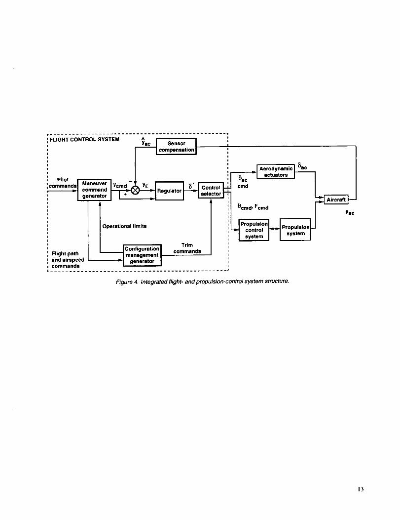
FlightControlSystem
TheE-7DSTOVLFCSconsistedofsixmajorcompo-nents(fig.4)whichweretheManeuverCommandGener-ator(MCG),ConfigurationManagementGenerator(CMG),Regulator,ControlSelector,Actuators,andSen-sorCompensation.Thecontrolsystemdesignemployedexplicitmodelfollowingwithproportionalandintegralgains,developedbyLinearQuadraticRegulator(LQR)synthesisaboutsixselecteddesignpoints:twoincruise,twointransition,andtwoinhover.AdetaileddescriptionoftheFCSanditsintegrationwiththepropulsionsystemisgiveninreference9.TheMCGhandledthecontrolmodeselectionmadebythepilot,shapedthepilotcontrolinputs,andgeneratedmission-levelcontrolcommands(i.e.,flightpathorveloc-itycommandsinresponsetopilotcontrolcommands).Fordesignpurposes,theflightenvelopewasdividedintothreeflightmodes:cruise,transition,andhover.Incruisethepilotcommandedaftnozzlethrust,rollrate,pitchrateandsideslip.Intransitionthepilotcommandedlongitudi-nalacceleration,rollrate,verticalflightpath(orflightpathrate)andsideslip.Inhover(theonlyflightmodeforwhichresultsarepresentedhere),thepilotcommandedlongitudinalvelocity,rollrate,verticalvelocity,andlat-eralvelocity.TherelationshipofinceptorstocommandedvariablesisdescribedintheSimulationExperimentsec-tionunderExperimentConfigurations.Washoutcircuitswereincludedtosmooththetransientresponsewhenswitchingbetweenflightmodes.Second-ordercommandgeneratorswerecustomizedtomeetmission-levelhan-dlingqualitiesspecificationsforSTOVLaircraftin thisclass.
TheCMGdefinedthepropulsionsystemtrimstatesfortheregulatorbasedonthespecificflightconfiguration,suchaswing-bornewithlandinggearup,wing-bornewithlandinggeardown,approach,hover,andon-groundoper-ation.Thetrimthrustsandnozzlepositionsweresched-uledasfunctionsofairspeedandflightpath angle. The
trim schedule was developed to minimize abrupt and large
amplitude thrust changes and attitude transients due to
these thrust changes.
The Regulator produced generalized actuator commands
to achieve model following characteristics and control
stability with respect to MCG control commands. The
regulator was designed based on linearized aircraft stabil-
ity derivatives and linear quadratic formulations with out-
put error weightings. Proportional plus integral controlwas used to ensure zero steady-state error.
The Control Selector converted generalized actuator
commands to physical actuator commands, whichincluded aerodynamic control surfaces, propulsive thrusts,and nozzle deflections. Pseudo-inverse transformation
was used to make this conversion, since the number of
physical control actuators was greater than that of the
generalized actuator commands. Each physical control
was weighted based on its effectiveness during the trans-formation. The pitch axis generalized actuator command
distribution was given higher priority than were the longi-
tudinal and vertical command degrees of freedom. The
Hanus anti-windup algorithm (ref. 10) was used to protect
system stability in the presence of the nonlinear character-istics of the physical actuators. The unmet generalizedactuator commands were fed back to the MCG to condi-
tion the control commands so that the generalized actuator
commands would always stay within the physical actua-tors' linear bounds.
The Actuators contained the dynamics of all aerodynamic
surfaces, reaction control system area control valves, ejec-
tor doors, and landing gear extension/retraction. All
actuator dynamics were simulated with first-order transfer
functions with appropriate time constants, rate limits, and
position limits.
The Sensor Compensation provided aircraft states in iner-
tial and body coordinates for the closed-loop feedback
control. First-order filters with corresponding cut-off fre-
quencies were used to remove high-frequency noise nor-
mally seen on the aircraft.
First-order complementary filters were employed to gen-
erate forward velocity and sideslip.
Simulation Experiment
A total of seven pilots took part in the simulator evalua-tion. All were highly trained and experienced test pilots.
Five pilots represented NASA or its support contractors,while two were employed by LFWC. The only ones with
extensive powered-lift flight experience were four of the
NASA-affiliated pilots.
Simulation Facility
Ames Research Center's VMS (fig. 5) was used for the
piloted evaluation. The VMS is a large-scale motion simu-
lator coupled to a VAX 9000 digital computer and an

EvansandSutherland CT5A visual scene generator. Com-
plete descriptions of all components of the VMS system
are given in reference I I. For the purpose of this experi-
ment, the cab and angular-motion support were rotated
90 deg, so that the large motion along the beam became
the longitudinal motion axis.
Figure 6 shows an interior view of the cockpit, includinglocations of the control inceptors. Figure 7 shows
schematically the instrument panel layout. The three-
window visual display provided a choice of reference tar-
gets for a precision hover task (fig. 8) or a small-ship
(DD963) scene for shipboard approach and landing(fig. 9).
All pertinent flight information was presented in a head-
up display (HUD), the details of which are shown in
figure 10. The symbology and drive laws for this HUD
were as described in reference 12, updated according toreference 13.
Evaluation Tasks and Procedures
In order to evaluate the E-7D handling qualities and
IFPCS performance in hover, two different types of pilot
tasks were used: (1) precision hover with reference to
fixed targets (fig. 8) and (2) shipboard approaches and
landings aboard a Spruance class destroyer (DD963,
fig. 9). The Cooper-Harper handling qualities rating
(HQR) scale (fig. II) (ref. 14) was used to evaluate thesetasks.
Figure 12 depicts the lateral and vertical precision hover
tasks. For the lateral task, the airplane's initial position
was 500 ft in front of the target array at a height of 50 ft.
That position was established by setting the simulation
initial conditions. From that position, the task was to
translate to and stabilize at a position 90 ft in front of the
right hand target, translate laterally and stabilize in front
of the left hand target, then translate and stabilize again at
the right hand target, all within a time limit of 55 sec. The
90-ft distance and the lateral/vertical position at each tar-
get were established visually according to the sight picture
illustrated in figure 8(c), where the "rabbit ears" appear toform a continuous horizontal bar, the corners of which
match the inside corners of the end squares on the back-
board. Allowable deviations for desired and adequate per-
formance were demonstrated visually to the pilot by
statically positioning the eye point prior to performing thetasks.
For vertical precision hover, beginning at the same initial
position, the task was to translate to and stabilize at aposition 90 ft in front of the lower target, ascend to and
stabilize in front of the upper target, then descend and
stabilize again at the lower target, all within 75 sec. For
the purpose of interpreting the Cooper-Harper rating scale
and assigning a handling qualities rating, allowable errors
were established corresponding to desired or adequate
performance. These errors for the precision hover tasks
are shown in figure 12.
Figure 13 depicts the shipboard landing task. From an ini-
tial height 50 ft above the landing deck and a position
400 fl directly aft of the station-keeping point (SKP),
which itself was 100 fl aft and 100 ft to port of the landing
deck touchdown point (TDP), the task was to translate
forward at a constant height to the SKP (which was
always fixed with respect to the ship axes), stabilize there,
then translate to a point directly over the TDP and
descend to the deck. The deck landing area was 40 ft by
70 ft. The target time from the SKP to touchdown was
35 sec. The normal descent rate with respect to the deck
was approximately 4 fps. Allowable touchdown errors for
desired or adequate performance are also shown in
figure 13.
Of the seven pilots who took part in the simulator evalua-
tion, Pilots A, B, C, and G had extensive background and
experience in jet-lift and other vertical and/or short take-off and landing (V/STOL) aircraft. Those with V/STOL
shipboard experience were pilots A and C. Pilots D, E,and F had considerable military experience in conven-
tional fighters. Pilots B and G did not formally evaluate
the precision hover tasks; all pilots evaluated the
shipboard landing task.
Experiment Configurations
The experiment variables of concern in this simulation
were divided into two control system configurations and
either two or four disturbance conditions, depending on
whether precision hover or shipboard landing tasks were
being performed.
Figure 14 shows the control-inceptor/command-variable
relationships for the "front-side" and "back-side" control
modes. All three flight phases (cruise, transition, and
hover) are included for clarity and completeness, though
only hover was evaluated formally. The front-side modewas so called because the manner of control was similar
to that of an airplane on the front side of the power curve;
that is, forward acceleration or velocity was controlled by
throttle movement and flightpath angle or vertical velocity
was controlled with longitudinal stick. The back-side
mode owed its name to the technique used on the back
side of the power curve, where flightpath or vertical
velocity was commanded with the left-hand controller
(the throttle) and pitch attitude (and consequently forward
velocity) was controlled using longitudinal stick. In thepresent experiment using the back-side mode, forward

accelerationwithvelocityholdinthetransitionphasewascommandedwithathumbwheel(theantennaelevationknob)onthethrottlegripand,inhover,longitudinalvelocitywascommandedwithlongitudinalstickforce.Switchesandbuttonsavailablefortrimmingthecom-mandedvariablesarealsoshownin figure14.Figure15showsthelongitudinalandlateralforcevs.deflectioncharacteristicsoftheright-handcontroller.Thiscon-troller,fromanF-16,hadverylimitedmotionandisreferredtohereinafterastheright-handforcecontrollerorforcestick.
Table3showsthedisturbanceconditionsusedintheexperiment.Ambientwindvelocityanddirectionareindi-catedfortheprecisionhovertask,withtheforward-aftaxisofthehovertargetsonaheadingof 163deg.Fortheshipboardlandingtask,bothambientwindandwindoverthedeckareshown,aswellasshipspeedandseastate.Basicstandardsforspecifyingthesedisturbancecondi-tionswereobtainedfromreference15.
Results and Discussion
Handling Qualities Evaluation
Precision hover- HQRs for the precision hover tasks are
presented individually for pilots A, C, D, E, and F in
table 4 and are also plotted in figure I6. The data are bro-ken down into lateral task and vertical task for the front-
side and back-side control modes, for two atmospheric
conditions: calm air and a 15 knot wind at 30 deg from the
left forward quarter with a turbulence level of 6 fps root
mean square (rms).
For the lateral task in calm air, the E-7D simulation using
the front-side control mode was consistently rated as satis-factory, or Level I. All other combinations for the lateraltask were distributed between Level I and Level 2
(adequate). (A complete discussion of Levels of flyingqualities and their relation to HQRs are presented in
ref. 16.) For the front-side mode, the HQRs given by
pilots D, E, and F, whose backgrounds were in conven-
tional non-powered-lift fighters and who stated that their
training and experience made the front-side mode more
natural to them (i.e., similar to the technique used in for-
mation flying or aerial refueling, wherein longitudinal
position is controlled with throttle and vertical position by
longitudinal stick) were consistently more favorable than
those given by pilots A and C. Pilots A and C had exten-sive V/STOL experience, where during low-speed and
hover operation the use of throttle to control vertical
velocity and right-hand center or side stick to control
translational velocity in the horizontal (X-Y) plane was
the normal technique. For this reason the back-side modewas more natural to them.
Except for pilots C and D, HQRs for the back-side modein the lateral task for both calm and disturbed conditions
were less favorable than for the front-side mode, in three
cases moving from Level I to Level 2 (notably with
pilot E). This difference was generally due to difficulty
establishing desired longitudinal position aggressively,
using the right-hand force controller. This controller
received many complaints regarding high force gradients
and almost no inceptor position feedback to the pilot,
causing a lack of smoothness of response (described as
"ratchetiness"), mostly in longitudinal translation.
For the vertical task, as for the lateral task, using the
front-side mode (fig. 16), the HQRs from the non-
V/STOL pilots were more favorable than those from the
V/STOL pilots, again demonstrating the difference in
acceptance of the front-side technique as it is influenced
by differences in training and experience. The most unfa-
vorable ratings fell deep in the Level 2 region. The major
factors driving these Level 2 ratings were imprecise con-
trol of heading and difficulty coordinating lateral and
directional control inputs during the initial horizontaliranslation to the vertical targets, cross-axis coupling
(lateral into vertical) introduced using the right-hand forcecontroller, and the need to coordinate left-hand throttle
inputs (for forward translation) and right-hand lateral
inputs to arrive at the desired position in front of the verti-
cal targets. Some difficulty capturing the upper vertical
target was also reported if the pilot used moderately
aggressive vertical inputs; some pilot-induced oscillation
(PIO) tendencies were seen, attributed to a somewhat long
apparent time constant in the vertical response combined
with the characteristics of the right-hand force controller.
In contrast, pilot F, who consistently rated this task/
control-mode combination Level 1, reported no adversecharacteristics other than a little cross-axis control
coupling with the force stick.
In corresponding atmospheric conditions, the vertical task
using the front-side mode was generally rated less favor-
ably than the lateral task, partly because of the more
extensive maneuver required to reach the necessary
X-Y position in front of the vertical targets. The apparentlong time constant of the vertical response, mentioned in
the preceding paragraph, was also a factor.
The vertical task using the back-side control mode was
rated consistently at 4.0. The principal reason for not rat-
ing these cases better than Level 2 was the persistent dif-
ficulty capturing precisely a desired longitudinal position
using the force stick. Good height control using throttledisplacement and relative ease of control of X-Y position
with a single controller, however, were reported.
On average, for these tasks using the front-side mode, the
presence of wind and turbulence required enough

additionalpilotcompensationtocauseadeterioration of
about one HQR. In the back-side mode, there was no
influence of wind and turbulence on the ratings.
Shipboard landing- HQRs for the shipboard landing task
are presented for pilots A through G in table 5. Figure 17
presents these data plotted for zero ship speed and as a
function of sea state and wind condition for a ship speedof 10 knots.
In calm conditions and with zero ship speed, the front-sidecontrol mode showed a division between V/STOL and
non-V/STOL pilots similar to that observed during the
precision hover tasks, though to a lesser degree, the aver-
age HQR for the non-V/STOL pilots being just one rating
point more favorable. Without disturbances of any kind,performance of the task with the front-side mode was
generally considered not difficult. Longitudinal velocity
control using the throttle was considered good to excel-
lent. Where the HQRs were not better than Level 2, the
pilots complained of the workload associated with coordi-
nation between the left-hand and right-hand controllers
when maneuvering in the X-Y plane, and of inadvertent
cross-axis inputs using the right-hand force controller(usually lateral control coupling into vertical).
For the front-side mode, the effect of added disturbances
on HQRs appeared to be largely due to the ship speed of
10 knots, with the increased sea state (and to some extent
wind and turbulence level) increasing the HQR spread
into the Level 3 region. Being a displacement controller,the throttle was found to be an effective means of com-
manding forward velocity to match that of the ship (i.e.,
the station-keeping point), almost lending itself to a "set
and forget" operation. For these cases, some pilots con-
tinued to comment adversely on the need for left-hand/
right-hand coordination as well as cross-axis contami-
nation using the force stick. Additional complaints were
also noted regarding the force stick. These were lack of
precision and smoothness of response (traceable to force
gradient or command sensitivity) and the need to hold
lateral stick force to match the ship velocity with the
aircraft heading into the wind, from 30 deg left of the
bow. There was a provision for trimming out the torce,
but the requirement to release force on the stick grip in
order to do so made that difficult. A similar problem was
encountered when attempting to trim out longitudinalforce in the back-side control mode, discussed in the fol-
lowing paragraphs.
For the back-side control mode in calm conditions, the
overall average HQR was a small fraction of a rating pointmore favorable than tbr the front-side mode. The division
in average HQR according to pilot background was also
present for the back-side mode, but to a much smaller
degree than for the front-side mode. Control of height
using the throttle controller was considered good toexcellent.
The addition of ship speed, sea state, and wind and tur-
bulence had an effect on mean level and spread of HQRs
similar to that observed for the front-side mode (fig. 17).
In the more severe conditions (sea state 3 and 4 plus windand turbulence) the majority of the pilots rated the back-
side mode equal to or better than the front-side mode; the
one exception was one of the non-V/STOL pilots, pilot F,who consistently tended to favor the front-side mode for
all tasks. The good vertical-velocity control using thethrottle controller carried over into these disturbed cases.
For the back-side mode at sea state 4, a wide discrepancy
in HQR was noted between pilots A and B. Landing per-
formance (touchdown position error and vertical velocity)was within desired limits for both pilots. Pilot A com-
plained of excessive workload in compensating for that
amount of deck motion, coupled with difficulty making
small, precise inputs using the force stick, whereas pilot Bconsidered the workload minimal and described the
maneuver from the SKP to touchdown as "not too bad."
Both pilots did report difficulty using the longitudinal trim
button on the force stick to relieve the steady forward
force required to approach the SKP and match the ship'svelocity. When actuating the trim button with the thumb,
it was necessary momentarily to relax hand pressure on
the stick, resulting in an unsteady approach to the SKP.
This initial phase, however, was not part of the formal
evaluation task and was not used in arriving at the HQRs.
The vast majority of comments on the back-side mode
were regarding the right-hand force controller and the
manner in which it was integrated into the control system.
At least three of the other pilots (not just A and B) found
the need to hold force to match ship speed troublesomeunless trimmed out. As mentioned earlier, the method of
trimming provided was not entirely satisfactory.
Other drawbacks of the force controller installation that
were mentioned were force gradient or sensitivity prob-lems similar to those encountered in the front-side mode,
leading to imprecise and "ratchety" control response, and
unwanted cross-axis inputs (this time in the X-Y plane). Amore optimal orientation of the force controller unit in the
cockpit could have alleviated some of the latter problem.
Both the front-side and back-side modes were evaluated
by pilots A and C, and the back side by pilot D, in 20 ft
visibility and zero ceiling, with ship speed of !0 knots and
sea state zero (fig. 17). These cases were given an HQR of
5, the same as for unlimited visibility, the pilots citing thesame control deficiencies as before, with minimal effect
of reduced visibility. Even with unlimited visibility, these
pilots relied mainly on the HUD for rate and position

guidance.Intherestrictedvisibilitycases,theHUDwasthesolesourceforrateandpositionguidance.
Becauseit lentitselfreadilytothetask,allpilotsreliedtosomedegreeontheHUDhovermodeforguidancetothetouchdownpointanddescenttolanding.ThedegreetowhicheachwasabletousetheHUDdependedonhisfamiliaritywiththesymbology.PilotsA,B,C,andGhadthemostexperiencewiththisdisplay,in thisandpreviousSTOVLsimulations.PilotsD,EandFhadpriorexperi-encewiththedisplayonlyduringthefixed-baseexerciseleadingtothepresentsimulationintheVMSand,conse-quently,lessHUDfamiliaritycoupledwithrelativelackofV/STOLexperience.SincetherewasinsufficienttimetobringtheselatterthreepilotstoalevelcomparablewiththatofpilotsA,B,C,andGsomeadverseeffectontheirratingswouldbeexpected.
Tosumupthepilotedevaluation,thefollowingstate-mentscanbemade:Fortheprecisionhovertasks,HQRs(consideringbothfront-sideandback-sidecontrol)werespreadoverarangecoveringLevelI andLevel2,withmoreratingsfallingintheLevel2rangeinthepresenceofmoderatewindandturbulence.Fortheshipboardlandingtaskwithzeroshipspeed,nodeckmotionandnowindandturbulence,HQRscoveredthesamerange(Level! andLevel2)asforprecisionhover.Theadditionof l0knotsof shipspeedresultedinLevel2ratingsinpracticallyeverycase;thefurtheradditionofdeckmotion,andmoderatewindandturbulenceincreasedtheHQRspreadwithintheLevel2rangeandevenbeyond.Single-axisresponse,withexceptionoftheyawaxis,didnotcausegreatproblems;however,cross-couplingeffectswereoftenpresentwhichwereannoyingorevenunsatis-factory.Yawcontrolwascharacterizedbyanapparentlongtimeconstantwhich,incombinationwithabsenceofaheading-holdloop,madecaptureofadesiredheadingdifficult.Severalpilots(notablypilotsAandC)foundtheright-handforcecontrollerdifficulttouseandunsuitableforjetborneflyingtasks.Objectionablecharacteristicswere found in the rudder pedals, attributed to their also
being force controllers. For jetborne maneuvering, those
pilots highly experienced in V/STOL operations (A, B, C,
and G) expressed a clear and sometimes forceful prefer-ence for the back-side control mode, wherein vertical
velocity was commanded with a left-hand controller and
longitudinal and lateral velocities were commanded by
means of a single right-hand controller.
Control Power Usage
The control power has direct consequence to the trim-
ming, maneuvering, and stabilization of the aircraft in any
flight condition. The control response requirements for
V/STOL, in terms of attitude change in one second, have
been specified by MIL-F-83300 (ref. 16) and
AGARD R-577-70 (ref. 17) for hover and low speed
flight operations. In reference 18 these specifications
have been related to control power and compared with
later experimental data. These comparisons suggest
that the roll control response specified in references 16
and 17 may not be adequate for shipboard landings in
severe weather conditions. One of the objectives of the
present experiment, therefore, was to examine the cont-
rol power usage requirements for the E-7D STOVLaircraft in adverse weather conditions.
The control power usage is contributed by both the aero-
dynamic control effectors and the propulsive thrusts. The
roll, pitch, and yaw control power usage for this experi-ment were calculated as follows:
IbB.C = (qSbAC,,_5 a + LpS)?xx
The control power usage in the shipboard landing task forvarious weather and sea state conditions is shown in
figure 18. It is shown that the roll control power usage inboth calm air and adverse weather conditions has
exceeded MIL-F-83300 control power requirement for
2 rad/sec attitude system with a damping ratio of 0.8944
(ref. 18). The pitch control power usage in adverse
weather condition has also exceeded the specified
requirement for a 2 rad/sec rate system.
Conclusions
A piloted motion simulator evaluation was completed in
support of a contractual study of the integration of flightand propulsion controls of a short takeoff, vertical landing
(STOVL) aircraft. The objectives of the study were to
validate the Design Methods for Integrated Control Sys-
tems (DMICS) concept, to evaluate the handling qualities,
and to assess control power usage during hover and land-
ing. From this evaluation the following conclusions aredrawn:
I. The closed-loop response of the E-7D with the inte-
grated flight- and propulsion-control system (IFPCS),which was designed following the DMICS procedure,
exhibited deficiencies which warrant further improvement
of the design process to fully validate the DMICS
concept.
2. With mild to moderate wind and turbulence, using
either the front-side or back-side control mode, handling
qualities were judged to be adequate (Level 2) to

marginallysatisfactoryfortheprecisionhovertasks.Undersimilaratmosphericconditionsandwith10knotsofshipspeed,boththefront-sideandback-sidemodesonaveragewereratedLevel2fortheshipboardlandingtask.Increasingseastateto3and4resultedinacorrespond-inglygreaterspreadofratings.
3.RollcontrolpowerusagedataindicatethatincreasingMIL-F-83300rollcontrolpowerspecificationsforhoveroperationsshouldbeconsidered.Furtherexperimentisrequiredtodetermineif MIL-F-83300pitchcontrolpowerspecificationisadequate.
4.Withnodisturbances,usingthefront-sidecontrolmode,averagehandlingqualitiesratings(HQR)wereinthesatisfactoryregion(LevelI) bothfortheprecisionhoverandshipboardlandingtasks.Inthesameconditions,usingtheback-sidecontrolmode,averagehandlingqualitiesratingswereborderlineLevelI/Level2forthelateralprecisionhovertask,Level2fortheverticalprecisionhovertask,andLevel1fortheshipboardlandingtask.5.Inthefront-sideorback-sidemode,useofthelimited-displacementforcecontroller(theright-handsidestick)formaneuveringinhoverresultedinobjectionablyhighpilotworkload.
References
I. Shaw, P. D. et ah Design Methods for Integrated
Control Systems. AFWAL-TR-88-2061, June1988.
2. Garg, Sanjay; Ouzts, Peter J.; Lorenzo, Carl F.; and
Mattern, Duane L.: IMPAC--An Integrated
Methodology for Propulsion and Airframe Con-trol. NASA TM- 103805, June 1991.
Franklin, James A.; Stortz, Michael W.; Gerdes,
Ronald M.; Hardy, Gordon H.; Martin, James L.;
and Engelland, Shawn A.: Simulation Evaluation
of Transition and Hover Flying Qualities of the
E-7A STOVL Aircraft. NASA TM-101015, Aug.1988.
Foley, W. H.; Albright, A. E.; Powers, D. J.; and
Smith, C. W.: Study of Aerodynamic Technology
for Single-Cruise-Engine V/STOL Fighter/Attack
Aircraft, Phase II Final Report, Volumes I and II.
NASA CR-177367, Aug. 1985.
Banks, Daniel W.; and Gatlin, Gregory M.: Longitu-
dinal and Lateral Aerodynamic Data from Tests of
an Advanced STOVL Fighter Employing a
Powered- Lift Ejector. NASA TM-87672, May1986.
.
4.
5.
6. Riley, Donald R.; Shah, Gautam H.; and Kuhn,
Richard E.: Low-Speed Wind-Tunnel Study ofReaction Control-Jet Effectiveness for Hover and
Transition of a STOVL Fighter Concept. NASATM-4147, Dec. ! 989.
7. Riley, Donald R.; Shah, Gautam H.; and Kuhn,Richard E.: Some Power-Induced Effects for
Transition Flight Measured on a 15-Percent Scale
E-7A STOVL Fighter Model. NASA TM-4188,June 1990.
8. Williams, J. E.; and Vukelich, S. R.: The USAF Sta-
bility and Control Digital DATCOM, Volumes I,
I1 and III. AFFDL-TR-79-3032, Apr. 1979.
9. Adibhatla, S.; Cooker, P.; Pajakowski, A.;
Romine, B.; Virnig, J.; and Bodden, D.:
STOVL Controls Technology, Volumes I,
II, and III. NASA CR-195361, July 1994.
10. Hanus, R.; Kinnaert, M.; and Henrotte, J. L.: Condi-
tioning Technique--A General Anti-Windup and
Bumpless Transfer Method. Automatica, vol. 23,
no. 6, Nov. 1987, pp. 729-739.
I I. Danek, George: Vertical Motion Simulator Familiar-ization Guide. NASA TM-103923, Oct. 1991.
12. Merrick, Vernon K.; Farris, Glenn G.; and Vanags,
Andrejs A.: A Head Up Display for Application to
V/STOL Aircraft Approach and Landing. NASATM- i02216, Jan. 1990.
13. Merrick, Vernon K.: Some VTOL Head-Up DisplayDrive-Law Problems and Solutions. NASA
TM- ! 04027, Nov. 1993.
14. Cooper, George E.; and Harper, Robert P., Jr.: The
Use of Pilot Rating in the Evaluation of Aircraft
Handling Qualities. NASA TND-5153, Apr. 1969.
15. Fortenbaugh, Robert L.: Mathematical Models
for the Aircraft Operational Environment of
DD-963 Class Ships. Vought Corp.
Rep. 2-55800/8R-3500, Sept. 1978.
16. Chalk, Charles R.; Key, David L.; Kroll, John, Jr.;Wasserman, Richard; and Radford, Robert C.:
Background Inlormation and User Guide for
MIL-F-83300 Military Specification--Flying
Qualities for Piloted V/STOL Aircraft.AFFDL-TR-70-88, Nov. 1971.
17. Anon.: V/STOL Landing, I -Criteria and Discussion.AGARD R-577-70, Dec. 1970.
18. Franklin, James A.: Criteria for Design of Integrated
Flight/Propulsion Control Systems for STOVL
Fighter Aircraft. NASA TP-3356, Apr. 1993.

TableI.E-7Dprincipaldimensions
Wingspan,ft 32.4Wingarea,ft2 630.6Aspectratio 1.66Taperratio 0. I 15
_, ft 23.56
MRC, % Cw 30.00
CG, % Ew 35.97
_ieL,R (max) deg +30
_ir (max) deg +_20
Table 2. Weight and moments of
inertia (hover, landing gear down)
Weight, Ib 17,000
lxx, slug_ft 2 4,415
lyy, slug-ft 2 29,413
Izz, slug-ft 2 29,963
lxz ' slug_ft 2 -70.51
Table 3. Task environmental conditions
At hover targets with heading At ship with heading 000 deg
Wind 163 deg
condition Vwind, _wind, rms turb., Vwind, _t/wind, Ship VWOD, _I/WOD, rms turb., Sea
kt deg fps kt deg speed, kt kt deg fps state
Wl
W2
W2A
W2B
0 0 0
15 133 3
15 133 6
15 133 6
0 0 0 0 0 0 0
8.11 292 10 15.04 330 3 0
8.11 292 10 15.04 330 6 3
8.11 292 10 15.04 330 6 4
Visibility Visualrange, Ceiling, ftcondition fl
V I Unlimited Unlimited
V6 20 0
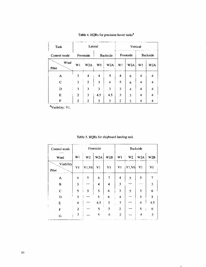
Table4.HQRsforprecisionhovertasksa
Task
Controlmode
ind
A
C
D
EF
avisibility:V1.
Lateral
Frontside
WI W2A
3 4
3 5
3 3
2 3i
2 2
Backside
WI W2A
4 5
3 4
3 3
4.5 4.5
3 3
Vertical
Frontside
WI W2A
4 6
5 6
3 4
3 3
2 3
Backside
W1 W2A
4 4
4 4
4 4
4 4
4 4
Table 5. HQRs for shipboard landing task
Control mode
Wind
A
B
C
D
E
F
G
Frontside
Wl W2 W2A W2B Wl
Vi VI,V6 VI Vl Vl
4
3
5
3
4
2
3
5
5
Backside
W2 [ W2A
Vl,V6 VI
W2B
VI
4.5
6
5
10

Win9. Area 630.6 fl2
• Aspect ratio 1.665• Taper ratio 0.115• Airfoil NACA 64A004• t/c 4%
Vertical tail• Ares 68.4 ft2
• Aspect ratio 1.294
. Taper ratio 0.437 _ _Airfoi.____L__i Biconvex
32 it 4,8 in;._.__
erall span.
..____ 49_15 in.
Figure 1. Three views of E-7D aircraft.
II

Ejector //_ o
(each side) . / //_1 °r 2-DCD
/nozzle
....__ v_.o,r.,.o,_'_,to.
Pitch RCS nozzle RCS nozzle
nozzle
_20o
TEj 110 o TVN
Figure 2. Arrangement of propulsive nozzles and RCS nozzles.
Fan with inletguide vanes (IGVs)
Bypass duct
Butterfly
_.(2-DCD)nozzle
Combustor Ventral nozzle
Compressor withvariable statorvanes (VSVs)
Figure 3. Propulsion system schematic diagram.
12
FUGHTCONTROLSYSTEM _ Sensor I
/ compensation
Pilot I
commands I Maneuvercommand
I generator
' yY_ I I _" I co,
_, Regulat°r I_'I sel,
Operational limits
:trol I_-
ctor r
TrimJConfiguration I
Flight path | management | commands
and airspeed _1 generator |commands............................................... J
-- I Aerodynamic
5a c v I actuators I I
cmd
ecmd' Fcmd , I " Yac
J PrcOPntlrSoi/n_.e, j Propulsionp
/ -.,- II "t"m I
Figure 4. Integrated flight- and propulsion-control system structure.
13

VMS NOMINAL OPERATIONAL MOTION
Velocity Accel
16 24
8 16
4 10
40 115
40 115
46 115
Vertical
Lateral
LongitudinalRoll
j j_J PitchYaw
_ All numbers, units in ft, deg, sac
Axis Displ
±30
,20
±4
±18
±18
±24
Figure 5. Vertical Motion Simulator.
14

Figure 6. Simulator cockpit interior.
TOUCHDOWNLIGHT
EJECTOR [-_DOORSWITCH
B
LANDINGGEAR
LIGHTS
LANDINGGEAR
HANDLE
HEAD-DOWNDISPLAY
Figure 7. Instrument pane/layout.
MODE SELECTSWITCHES
MODE SELECTALSO AVAILABLE
ON SIDESTICK
]5

Lateral task Vertical task
(a) Hover target arrangements
(b) Target close up
Black White
ed
(c) Target appearance when in position
Figure 8. Precision hover target display.
]6

Figure 9. Small ship landing display.
17

100
5oI
m5
o
I I
ml0
©
3O
1. Horizon bar and pitch ladder
2. Engine (fan) percent RPM
3. Resultant thrust vector angle
4. Horizontal distance to touchdown point
5. Landing pad symbol
6. Airspeed
7. Ground speed
8. Height above ground/sea
9. Vertical velocity
10. Horizontal velocity vector
11. Horizontal velocity predictor ball
12. Vertical velocity predictor diamond
13. Allowable vertical velocity ribbon14. Ground/deck bar
Figure 10. STOVL head-up display; hover mode.
]8

I Pilot decisions I
warrant
improvement
Deficiencies
improvement
Improvementmandatory
Excellent
Highly desirablePilot compensation not a factorfor desired performance
Pilot compensation not a factorfor desired performance
_i_ Fair - Some mildly77!_ unpleasant deficiencies
i_ Minor but annoying_,__:_ deficiencies
Minimal pilot compensationrequired for desired performance
Desired performance requiresmoderate pilot compensation
Moderately objectionable Adequate performance requires• _:,_ deficiencies considerable pilot compensation
Very ob)ectJonabJe buttolerable deficiencies
Major deficiencies
Adequate performance requiresextensive pilot compensation
Adequate performance notattainable with maximumtolerable pilot compensation.Controllability not in question
Considerable pilot compensationis required for control
ii!iiiiiiii_ii
::::: :::::
Major deficiencies Intense pilot compensationJsrequired to retain control
Major deficiencies Control will be lost during someportion of required operation
* Definition of required operation involves designation of flightphase and/or subphases with accompanying conditions.
Figure 11. Handling-qualities rating scale.
]9

_l---_----t_
I I
iA_-..
I.-
.!
°°1_-Ft .t-i
o,ii"o e- 1:: _
' .aO -_"_:
,IgIom
i
0
cm
e-
o..i
,,..,J
2O

i -"_l v |_'_lO
e-,
O
Ovl
u)
C_
2]

(a)
• Thrust• Accel/decel with velocity hold
• Longitudinal velocity
UHF/VHF switch • Roll rate• Roll rate/attitude hold
• No function • Lateral velocity/_-_f • Accalldecal trim f
• L_ngitudinal velocity trim llmw_ _mz_
Targat management _ _'_ _
• Nofunction \ ' ' /• No function _ J• Vertllat velocity trim
• Pitch rate
• Flight path rate/flight path hold
• Vertical velocity
Trim switch
• Pitch/roll trim• Pitch/roll
attitude trim• Pitch attitude trim
Rudder pedels - • Sideslip• Sideslip• Yaw rate
• Cruise• Transition• Hover
(b)
• Thrust• Flight path
/_* Vertical velocity
• No function• AcceVdecel with
velocity hold• No function
Rudder pedels - • Sideslip• Sideslip
• Pitch rate• Pitch rate/attitude hold
• Longitudinal velocity
• Roll rate J• Roll rate/attitude hold
• Lateral velocity _ mm_
t Trim switch• Pitch/roll• Pitch/roll attitude• Pitch attitude
Target management• No function• No function• Velocity trim
• Yaw rate/heading hold
Figure 14. Control modes and inceptor configurations. (a) Front-side mode, (b) back-side mode.
2.2

- Calibration I
0 _'_ \ \ \ \ \ _ t°leran_/
0 5 -- 10 1520 25 ---------.-L
_a) Force, POUnds 30 35
.20 -
.15
_ Calibration
.os
(b) Force, POunds 20
Figure 15. Right-hand controller.force gradients. (a) Longitudinal, (b) lateral.
23

n-O-I-
10--
8 m
6-
4 -
2 -
LATERAL TASK
Pilot
OA
Oc_D
zI E
rl F
VERTICAL TASK
Open symbols - frontside mode
Filled symbols - backside mode
o @
_1_]
I0/0
I I15/6 0/6
Disturbance, wind/turb., klsfiVsec rms
Figure 16. Handling-qualities ratings for precision hover tasks.
Inadequate(Level 3)
Adequate(Level 2)
A ee_l
Satisfactory(Level 1)
I15/6
24

o3:
10 m
8
6 u
4_
2 n
VS= 0
Pilot
O A
[]B
_cD
E
F
Open symbols - frontside modeFilled symbols - backside modeFlagged symbols - ceiling zero, visibility 20 ft.
VS=10 kt
® •
QA •A
o n a _ _ _a
[] •• []
[]QA Eliza
(_ dll
I I I0 2 3
Sea state
Figure 17. Handling-qualities ratings for the shipboard landing task.
Inadequate(Level 3)
Adequate(Level 2)
Satisfactory(Level 1)
25

II II
_, ¢--
._g
E
r..)
Q
I I I
DOra •
oee_
I I I
e cpe_ e C)
e ee e ee_e
0
I I I
r_
_m
m
o
,0
o
r_
26

REPORT DOCUMENTATION PAGE FormApprove_OMB No. 0704-0188
Publicreportingburden for this collectionof informationis estimated to average 1hour per response, includingthe time for reviewinginstructions,searching existing data sources,gatheringand maintaining the data needed, and completingand reviewingthe collectionof information. Send comments regardingthis burdenestimate or any other aspect of thiscollectionof information, includingsuggestionsfor reducing this burden, to WashingtonHeadquarters Services.Directorate for informationOperations and Reports, 1215 JeffersonDavis H ghway, Sute 1204, Ari ngton,VA 22202-4302. and to the Off ce of Managementand Budget.Paperwork ReductionProject(0704-0188), Washington, DC 20503.
1. AGENCY USE ONLY (Leave blank) 2. REPORT DATE 3. REPORT TYPE AND DATES COVERED
June 1995 Technical Memorandum
!4. TITLE AND SUBTITLE 5. FUNDING NUMBERS
Moving Base Simulation of an Integrated Flight and Propulsion
Control System for an Ejector-Augmentor STOVL Aircraft in Hover
6. AUTHOR(S)
Walter E. McNeill, William W. Chung, and Michael W. Stortz
7. PERFORMING ORGANIZATION NAME(S) AND ADDRESS(ES)
505-68-32
8. PERFORMING ORGANIZATIONREPORT NUMBER
Ames Research Center
Moffett Field, CA 94035-1000
9. SPONSORING/MONITORING AGENCY NAME(S) AND ADDRESS(ES)
National Aeronautics and Space Administration
Washington, DC 20546-0001
A-950046
10. SPONSORING/MONITORINGAGENCY REPORT NUMBER
NASA TM- 108867
11. SUPPLEMENTARYNOTES
Point of Contact: William W. Chung, Ames Research Center, MS 243-5Moffett Field, CA 94035-1000; (415) 604-1496
12a. DISTRIBUTION/AVAILABILITYSTATEMENT
Unclassified-Unlimited
Subject Category - 05
12b. DISTRIBUTION CODE
13. ABSTRACT (Maximum 200 words)
A piloted motion simulator evaluation, using the NASA Ames Vertical Motion Simulator, was
conducted in support of a NASA Lewis contractual study of the integration of flight and propulsion
systems of a STOVL aircraft. Objectives of the study were to validate the Design Methods for Integrated
Control Systems (DMICS) concept, to evaluate the handling qualities, and to assess control power
usage. The E-7D ejector-augmentor STOVL fighter design served as the basis for the simulation.
Handling-qualifies ratings were obtained during precision hover and shipboard landing tasks. Handling-
qualities ratings for these tasks ranged from satisfactory to adequate. Further improvement of the design
process to fully validate the DMICS concept appears to be warranted.
14. SUBJECTTERMS
STOVL, Integrated flight/propulsion control system, DMICS
17. SECURITY CLASSIFICATIONOF REPORT
Unclassified
NSN 7540-01-280-5500
18. SECURITY CLASSIFICATIONOF THIS PAGE
Unclassified
19. SECURITY CLASSIFICATIONOF ABSTRACT
15. NUMBER OF PAGES
3l16. PRICE CODE
A0320. LIMITATION OF ABSTRACT
Standard Form 298 (Rev. 2-89)Prescribed by ANSI Std. Z39-18
298-102
