movi-plc® advanced dhr41b fieldbus interfaces ethernet/ip
TRANSCRIPT
Drive Technology \ Drive Automation \ System Integration \ Services
MOVI-PLC® advanced DHR41B ControllerEtherNet/IP, Modbus/TCP andPROFINET IO Fieldbus Interfaces
ManualEdition 03/200916730410 / EN

SEW-EURODRIVE – Driving the world

Manual – MOVI-PLC® advanced DHR41B for EtherNet/IP, Modbus/TCP and PROFINET IO 3
1 General Notes......................................................................................................... 61.1 How to use this documentation ...................................................................... 61.2 Structure of the safety notes .......................................................................... 61.3 Rights to claim under limited warranty ........................................................... 71.4 Exclusion of liability ........................................................................................ 71.5 Copyright........................................................................................................ 7
2 Safety Notes ........................................................................................................... 82.1 Other applicable documentation .................................................................... 82.2 Bus systems................................................................................................... 82.3 Safety functions ............................................................................................. 82.4 Hoist applications........................................................................................... 82.5 Product names and trademarks ..................................................................... 82.6 Disposal ......................................................................................................... 8
3 Preface .................................................................................................................... 93.1 Content of this manual ................................................................................... 93.2 Characteristics ............................................................................................... 9
3.2.1 Process data exchange ...................................................................... 93.2.2 Parameter access ............................................................................... 93.2.3 Monitoring functions .......................................................................... 10
4 Assembly and Installation Notes for Ethernet................................................... 114.1 Connecting MOVI-PLC® advanced DHR41B to an Ethernet network ......... 114.2 Pin assignment of X30-1 and X30-2 ............................................................ 114.3 Shielding and routing bus cables ................................................................. 124.4 The integrated Ethernet switch .................................................................... 134.5 Setting the DIP switches .............................................................................. 144.6 Status LED of the DHR41B option............................................................... 15
4.6.1 Status LEDs in EtherNet/IP and Modbus/TCP operation .................. 154.6.2 Status LEDs in PROFINET operation ............................................... 164.6.3 Link/Activity LEDs ............................................................................. 17
4.7 TCP/IP addressing and subnetworks........................................................... 184.8 Setting the IP address parameters............................................................... 204.9 Procedure for unit replacement.................................................................... 22
5 Configuration and Startup (EtherNet/IP) ............................................................ 235.1 Validity of the EDS file for DHR41B ............................................................. 235.2 Configuring the master (EtherNet/IP scanner) ............................................. 245.3 Settings in MOVI-PLC® advanced DHR41B ................................................ 27
5.3.1 Process data configuration ............................................................... 275.3.2 Status of the fieldbus interface ......................................................... 27
5.4 Configuration examples in RSLogix 5000.................................................... 285.4.1 MOVI-PLC® advanced DHR41B with 16 PD data exchange ............ 285.4.2 Access to the parameters of MOVI-PLC® advanced DHR41B ......... 315.4.3 Access to unit parameters of downstream units ............................... 36
6 The Ethernet Industrial Protocol (EtherNet/IP) ................................................ 376.1 Introduction .................................................................................................. 376.2 Process data exchange ............................................................................... 376.3 CIP object directory...................................................................................... 386.4 Return codes for parameter setting via explicit messages........................... 51

4 Manual – MOVI-PLC® advanced DHR41B for EtherNet/IP, Modbus/TCP and PROFINET IO
7 Configuration and Startup (Modbus/TCP) ......................................................... 557.1 Unit description file for Modbus/TCP............................................................ 557.2 Configuration of the master (Modbus scanner)............................................ 557.3 Settings in MOVI-PLC® advanced DHR41B ................................................ 58
7.3.1 Process data configuration ............................................................... 587.3.2 Status of the fieldbus interface ......................................................... 58
7.4 Configuration examples in PL7 PRO ........................................................... 597.4.1 MOVI-PLC® advanced DHR41B with 16 PD data exchange ............ 59
7.5 Examples for data exchange via Modbus/TCP............................................ 617.5.1 Writing and reading process data ..................................................... 627.5.2 Parameter access ............................................................................. 64
8 The Modbus Protocol (Modbus/TCP) ................................................................. 668.1 Introduction .................................................................................................. 66
8.1.1 Mapping and addressing .................................................................. 668.1.2 Services (function codes) .................................................................. 678.1.3 Access .............................................................................................. 67
8.2 Protocol structure......................................................................................... 688.2.1 Header .............................................................................................. 688.2.2 Service FC3 Read holding registers ................................................ 698.2.3 Service FC16 Write multiple registers .............................................. 708.2.4 Service FC23 Read/write multiple registers ..................................... 718.2.5 Service FC43 Read device identification ......................................... 72
8.3 Connection management ............................................................................. 738.3.1 Sending process output data (requesting a controlling connection) . 738.3.2 Dropping connections ....................................................................... 748.3.3 Timeout monitoring ........................................................................... 74
8.4 Parameter access via Modbus/TCP............................................................. 758.4.1 Procedure with FC16 and FC3 ......................................................... 758.4.2 Procedure with FC23 ........................................................................ 758.4.3 Protocol structure .............................................................................. 768.4.4 MOVILINK® parameter channel ........................................................ 77
8.5 Fault codes (exception codes) ..................................................................... 78
9 Fault Diagnostics for Operation on EtherNet/IP and Modbus/TCP ................. 799.1 Diagnostic sequence.................................................................................... 79
10 PROFINET IO Configuration................................................................................ 8110.1 Configuring the PROFINET IO controller ..................................................... 81
10.1.1 Installing the GSD file ...................................................................... 8110.1.2 Assigning a PROFINET device name .............................................. 82
10.2 Configuring the PROFINET connection for MOVI-PLC® advanced DHR41B ...................................................................................... 8410.2.1 Creating a new project ..................................................................... 8410.2.2 Configuring a station ........................................................................ 86
10.3 PROFINET configuration with topology detection........................................ 8810.3.1 Introduction ...................................................................................... 8810.3.2 Configuring the PROFINET topology ............................................... 8910.3.3 Changing the port properties ........................................................... 9110.3.4 Topology diagnostics ....................................................................... 9310.3.5 Port statistics .................................................................................... 94
10.4 PROFINET diagnostics alarms .................................................................... 9610.4.1 Switching on the diagnostic alarms .................................................. 9610.4.2 Determining the cause of a fault ...................................................... 97

Manual – MOVI-PLC® advanced DHR41B for EtherNet/IP, Modbus/TCP and PROFINET IO 5
11 Operating Behavior (PROFINET IO).................................................................... 9811.1 Process data exchange with MOVI-PLC® advanced DHR41B.................... 9811.2 Settings in MOVI-PLC® advanced DHR41B .............................................. 100
11.2.1 Status of the PROFINET fieldbus interface .................................... 10011.3 Parameterization via PROFIdrive data record 47 ...................................... 102
11.3.1 Introduction to PROFINET data records ........................................ 10211.3.2 Structure of the PROFINET parameter channel ............................ 10511.3.3 Parameter setting procedure via data record 47 ............................ 10611.3.4 Controller processing sequence ..................................................... 10711.3.5 Addressing downstream inverters .................................................. 10811.3.6 MOVILINK® parameter requests .................................................... 10911.3.7 PROFIdrive parameter requests .................................................... 114
12 Error Diagnostics on PROFINET....................................................................... 11912.1 Diagnostic procedure ................................................................................. 119
12.1.1 Diagnostics problem 1: MOVI-PLC® advanced DHR41B not working on PROFINET IO ......................... 120
12.1.2 Diagnostics problem 2: No process data exchange with the I/O controller ...................................................................... 121
13 Appendix............................................................................................................. 12213.1 Parameter access via EtherNet/IP to downstream units............................ 12213.2 Parameter access via Modbus/TCP or PROFINET to downstream units .. 12313.3 Parameter access via engineering interface to downstream units............. 12413.4 Glossary ..................................................................................................... 125
14 Index.................................................................................................................... 126

6 Manual – MOVI-PLC® advanced DHR41B for EtherNet/IP, Modbus/TCP and PROFINET IO
1 How to use this documentationGeneral Notes
MOVI-PLC¬???/IP, Modbus/TCP und PROFINET IO1 General Notes1.1 How to use this documentation
The documentation is an integral part of the product and contain important informationon operation and service. The documentation is written for all employees who assemble,install, startup, and service this product.
1.2 Structure of the safety notesThe safety notes in this documentation are designed as follows:
Pictogram SIGNAL WORDType and source of danger.Possible consequence(s) if disregarded.• Measure(s) to prevent the danger.
Pictogram Signal word Meaning Consequences if disregarded
Example:
General danger
Specific danger,e.g. electric shock
DANGER Imminent danger Severe or fatal injuries
WARNING Possible dangerous situation Severe or fatal injuries
CAUTION Possible dangerous situation Minor injuries
NOTICE Possible damage to property Damage to the drive system or its environ-ment
TIP Useful information or tip.Simplifies the handling of the drive system.

Manual – MOVI-PLC® advanced DHR41B for EtherNet/IP, Modbus/TCP and PROFINET IO 7
1Rights to claim under limited warrantyGeneral Notes
1.3 Rights to claim under limited warrantyA requirement of fault-free operation and fulfillment of any rights to claim under limitedwarranty is that you adhere to the information in the documentation. Read the documen-tation before you start working with the unit!Make sure that the documentation is available to persons responsible for the system andits operation as well as to persons who work independently on the unit. You must alsoensure that the documentation is legible.
1.4 Exclusion of liabilityYou must observe this publication and the documentation of the connected units fromSEW-EURODRIVE to ensure safe operation and to achieve the specified product char-acteristics and performance requirements. SEW-EURODRIVE assumes no liability forinjury to persons or damage to equipment or property resulting from non-observance ofthe operating instructions. In such cases, any liability for defects is excluded.
1.5 Copyright© 2008 - SEW-EURODRIVE. All rights reserved.Copyright law prohibits the unauthorized duplication, modification, distribution, and useof this document, in whole or in part.

8 Manual – MOVI-PLC® advanced DHR41B for EtherNet/IP, Modbus/TCP and PROFINET IO
2 Other applicable documentationSafety Notes
2 Safety Notes2.1 Other applicable documentation
Note also the following documentation:• 'MOVI-PLC ® advanced DHE41B/DHF41B/DHR41B Controller' manual• 'MOVI-PLC® Programming in the PLC Editor' manualThe following publications and documents apply to the connected units:• Operating instructions of the units
(Units are, for example, MOVIDRIVE® B, MOVITRAC® B, MOVIAXIS®)• For units with functional safety technology, also the respective
'Safe Disconnection - Conditions' manuals
2.2 Bus systemsMOVI-PLC® advanced DHR41B supports various bus systems. A bus system makes itis possible to adapt frequency inverters to the particulars of the machinery within widelimits. As with all bus systems, there is a danger of invisible, external (as far as the in-verter is concerned) modifications to the parameters which give rise to changes in theunit behavior. This may result in unexpected, though not uncontrolled, system behavior.
2.3 Safety functionsThe MOVIDRIVE® MDX60B/61B and MOVITRAC® B inverters may not perform safetyfunctions without higher-level safety systems. Use higher-level safety systems to ensureprotection of equipment and personnel. For safety applications, ensure that the informa-tion in the following publications is observed: 'Safe Disconnection for MOVIDRIVE®
MDX60B/61B, MOVITRAC® B'.
2.4 Hoist applicationsMOVIDRIVE® MDX60B/61B and MOVITRAC® B are not designed for use as a safetydevice in hoist applications. Use monitoring systems or mechanical protection devices as safety equipment to avoidpossible damage to property or injury to people.
2.5 Product names and trademarksThe brands and product names in this manual are trademarks or registered trademarksof the titleholders.
2.6 Disposal
Observe the applicable national regulations.?Dispose of the following materials separately in accordance with the country-specificregulations in force, as:• Electronics scrap• Plastic• Sheet metal• Copper

Manual – MOVI-PLC® advanced DHR41B for EtherNet/IP, Modbus/TCP and PROFINET IO 9
3Content of this manualPreface
3 Preface3.1 Content of this manual
This user manual describes:• The startup procedure for MOVI-PLC® advanced DHR41B on the fieldbus systems
EtherNet/IP, Modbus/TCP and PROFINET IO.• The configuration of the EtherNet/IP master with EDS files.• The configuration of the Modbus/TCP master.• The configuration of the PROFINET master using GSDML files.The creation of IEC programs or the connection of SEW drives to the system bus inter-faces of MOVI-PLC® is not described.
3.2 CharacteristicsThe powerful, universal fieldbus interfaces of the DHR41B option enable a connectionto higher-level automation systems via EtherNet/IP, Modbus/TCP and PROFINET IO.
3.2.1 Process data exchange
The MOVI-PLC® advanced DHR41B controller offers digital access to a special datarange via the Industrial Ethernet interface. This data range is evaluated by IEC 61131-3as process input and output data to a higher-level controller. The meaning of the trans-ferred data depends on the IEC program.
3.2.2 Parameter access
This parameter data exchange enables you to implement applications for which all im-portant parameters are stored in the higher-level programmable controller, so that thereis no need to set parameters manually in the MOVI-PLC® advanced DHR41B. In EtherNet/IP operation, the parameters of the inverter are set by the controller solelyvia explicit messages.In Modbus/TCP operation, the controller can access the parameters via the 8 byteMOVILINK® parameter channel.In PROFINET operation, two parameter access options are available:• The PROFIdrive data record 47 offers access to all unit information also in
PROFINET operation• The PROFIBUS DP-V1 parameter mechanisms offers universal access to all unit in-
formation.

10 Manual – MOVI-PLC® advanced DHR41B for EtherNet/IP, Modbus/TCP and PROFINET IO
3 CharacteristicsPreface
3.2.3 Monitoring functions
Using a fieldbus system requires additional monitoring functions, for example, time mon-itoring of the fieldbus (fieldbus timeout) or rapid stop concepts. For example, you canadapt the monitoring functions specifically to your application in the IEC program. Youcan determine, for instance, which fault responses should be triggered in the event of abus error. For many applications, a rapid stop function is useful. However, you can alsofreeze the last setpoints so that the drive continues to operate with the most recently val-id setpoints. As the range of functions for the control terminals is also available in field-bus mode, you can continue to implement rapid stop concepts using the terminals ofMOVI-PLC® advanced DHR41B, irrespective of the fieldbus used.

Manual – MOVI-PLC® advanced DHR41B for EtherNet/IP, Modbus/TCP and PROFINET IO 11
4Connecting MOVI-PLC® advanced DHR41B to an Ethernet networkAssembly and Installation Notes for Ethernet
4 Assembly and Installation Notes for EthernetOnly the connection to Ethernet networks via X30:1 and X30:2 is described in this chap-ter. Connection and functions via X37 (engineering) are described in the "MOVI-PLC®
advanced DHE41B/DHF41B/DHR41B" manual.
4.1 Connecting MOVI-PLC® advanced DHR41B to an Ethernet network
4.2 Pin assignment of X30-1 and X30-2Use prefabricated, shielded RJ45 plug connectors compliant with IEC 11801 edition 2.0,category 5.
Front viewMOVI-PLC® advanced DHR41B controller
DesignationLEDDIP switchesTerminal
Function
64249AXX
LEDL14L13
L14L13
L12L11
In EtherNet/IP and Modbus/TCP operation:MODULE STATUSNETWORK STATUS
In PROFINET operation:RUNBUS FAULT
ReservedReserved
X30-1: Ethernet connectionLED Link (green)LED Activity (yellow)
X30-2: Ethernet connectionLED Link (green)LED Activity (yellow)
DIP switches 20 = ON Resets the address parameters to their default values and deactivates DHCP• IP address: 192.168.10.4• Subnet mask: 255.255.255.0• Gateway: 192.168.10.4
21 = ON21 = OFF
EtherNet/IP and Modbus/TCP protocol is activePROFINET protocol is active
X38: CAN for safety-rele-vant communication
X38:1X38:2X38:3
ReservedReservedReserved
DHR41B
22
01
X30-1
X30-2
L14
L13
ON
1
2
3
X38
L12
L11
54174AXX
A View from front B View from back
[1] Pin 1 TX+ Transmit Plus [2] Pin 2 TX- Transmit Minus
[3] Pin 3 RX+ Receive Plus [6] Pin 6 RX- Receive Minus
[3] [2] [1]23
6
1
[6]
A B

12 Manual – MOVI-PLC® advanced DHR41B for EtherNet/IP, Modbus/TCP and PROFINET IO
4 Shielding and routing bus cablesAssembly and Installation Notes for Ethernet
DHR41B - Ethernet connection
To connect DHR41B to the Ethernet, connect the Ethernet interface X30-1 or X30-2(RJ45 plug connector) to the other network stations using a category 5, class D twisted-pair cable in accordance with IEC 11801 edition 2.0. The integrated switch provides sup-port for realizing a line topology and offers auto crossing functions.
4.3 Shielding and routing bus cablesOnly use shielded cables and connection elements that also meet the requirements ofcategory 5, class 2 in compliance with IEC 11801 edition 2.0.Correct shielding of the bus cable attenuates electrical interference that can occur in in-dustrial environments. The following measures ensure the best possible shielding:• Manually tighten the mounting screws on the connectors, modules, and equipotential
bonding conductors.• Use only connectors with a metal housing or a metalized housing.• Connect the shielding in the connector over a wide surface area.• Apply the shielding of the bus cable on both ends.• Route signal and bus cables in separate cable ducts. Do not route them parallel to
power cables (motor leads).• Use metallic, grounded cable racks in industrial environments.• Route the signal cable and the corresponding equipotential bonding close to each
other using the shortest possible route.• Avoid using plug connectors to extend bus cables.• Route the bus cables closely along existing grounding surfaces.
TIPS• According to IEC 802.3, the maximum cable length for 10/100 MBd Ethernet
(10BaseT / 100BaseT), e.g. between two network stations, is 100 m.• We recommend that you do not directly connect non-SEW end devices to the
DHR41B option in order to minimize the load on the end devices in EtherNet/IP net-works caused by undesired multicast data traffic. Connect non-SEW devices via anetwork component that supports the IGMP snooping functionality (e.g. managedswitch).
CAUTIONIn case of fluctuations in the ground potential, a compensating current may flow via thebilaterally connected shield that is also connected to the protective earth (PE). Makesure you supply adequate equipotential bonding according in accordance with relevantVDE regulations in such a case.

Manual – MOVI-PLC® advanced DHR41B for EtherNet/IP, Modbus/TCP and PROFINET IO 13
4The integrated Ethernet switchAssembly and Installation Notes for Ethernet
4.4 The integrated Ethernet switchYou can use the integrated Ethernet switch to achieve line topologies known from thefieldbus technology. Other bus topologies, such as star or tree, are also possible. Ringtopologies are not supported.
Auto-crossing The two ports leading out of the Ethernet switch have auto-crossing functionality. Thismeans that they can use both patch and cross-over cables to connect to the next Ether-net station.
Auto-negotiation The baud rate and the duplex mode is negotiated by both Ethernet nodes when estab-lishing the connection. For this purpose, both Ethernet ports of the EtherNet/IP connec-tion support an auto-negotiation functionality and work with a baud rate of either100 Mbit or 10 Mbit in full duplex or half-duplex mode.
Notes on multi-cast handling
• The integrated Ethernet switch does not provide a filter function for Ethernet multicast telegrams. Multicast telegrams that are usually sent from the adapters(DHR41B) to the scanners (PLC) in EtherNet/IP networks are passed on to all switchports.
• IGMP Snooping (e.g. Managed Switches) is not supported.• SEW-EURODRIVE therefore recommends to connect the DHR41B option in Ether-
Net/IP networks only with network components that support IGMP snooping (e.g.managed switch) or that have safety mechanisms integrated against excess multi-cast load (e.g. units from SEW-EURODRIVE). Units that do not have this integratedfunction can fail due to high network loads.
TIPThe number of Industrial Ethernet switches connected in line impacts on the telegramrun time. If a telegram passes through the units, the telegram runtime is delayed by theStore & Forward function of the Ethernet switch:• for a telegram length of 64 bytes by approximately 10 μs (at 100 Mbit/s)• for a telegram length of 1500 bytes by approximately 130 μs (at 100 Mbit/s)This means that the more units a telegram has to pass through, the higher the telegramruntime is.

14 Manual – MOVI-PLC® advanced DHR41B for EtherNet/IP, Modbus/TCP and PROFINET IO
4 Setting the DIP switchesAssembly and Installation Notes for Ethernet
4.5 Setting the DIP switches
20 (Def IP) if the switch "20" is set to "1" (= right = ON), the following default IP address parametersare set when the DC 24 V backup voltage is switched on.• IP address: 192.168.10.4• Subnet mask: 255.255.255.0• Default gateway: 192.168.10.4• P785 DHCP / Startup configuration: Saved IP parameters (DHCP is deactivated)
21 (protocol) DIP switch "21" is used to set the protocol that is used for communication.• 21 = "1" (= right = ON): The EtherNet/IP and Modbus TCP/IP fieldbus protocol is
active.• 21 = "0" (= left = OFF): The PROFINET fieldbus protocol is active.
TIPBefore each change to the DIP switches, disconnect the MOVI-PLC® advancedDHR41B control card from the voltage supply. The DIP switch settings are adoptedduring initialization only.
64248AXX
DHR41B
22
01
ON

Manual – MOVI-PLC® advanced DHR41B for EtherNet/IP, Modbus/TCP and PROFINET IO 15
4Status LED of the DHR41B optionAssembly and Installation Notes for Ethernet
4.6 Status LED of the DHR41B optionThe LEDs of the DHR41B option card indicate the current status of the DHR41B optionand the fieldbus system. Depending on the set protocol, the LEDs have the followingmeaning.
4.6.1 Status LEDs in EtherNet/IP and Modbus/TCP operation
The status of the fieldbus interface corresponding to the LED status is shown inchapter 9.
LED L13 (NETWORK STATUS)
The LED L13 (NETWORK STATUS) indicates the state of the fieldbus system.
LED L14 (MODULE STATUS)
LED L14 (MODULE STATUS) indicates that the bus electronics are operating correctly.
64247AXX
DHR41B
L14
L13
States of the NET-WORK STATUS LED
Meaning
Off The DHR41B option does not yet have any IP parameters.
Flashing green/red The DHR41B option card performs an LED test.
Flashing green There is no controlling IO connection.
Green There is a controlling EtherNet/IP or Modbus/TCP connection.
Red Conflict detected in the assigned IP addresses. Another station in the network uses the same IP address.
Flashing red The previously established controlling IO connection is in timeout status. The status is reset by restarting communication.
States of the MOD-ULE STATUS LED
Meaning
Off The DHR41B option card is not supplied with voltage or is defective
Flashing green • If the NETWORK STATUS LED is off at the same time, the TCP/IP stack of the DHR41B option card will be started. If this status continues and DHCP is acti-vated, the DHR41B option waits for data from the DHCP server.
• If the NETWORK STATUS LED is flashing green at the same time, the applica-tion of the DHR41B option card is started.
Flashing green/red The DHR41B option card performs an LED test.
Green Indicates the standard operating state of the DHR41B option card
Red The DHR41B option card is in fault state.
Flashing red Conflict detected in the assigned IP addresses. Another station in the network uses the same IP address.

16 Manual – MOVI-PLC® advanced DHR41B for EtherNet/IP, Modbus/TCP and PROFINET IO
4 Status LED of the DHR41B optionAssembly and Installation Notes for Ethernet
4.6.2 Status LEDs in PROFINET operation
LED L13 (BUS-FAULT)
The LED L13 (BUS FAULT) displays the status of the PROFINET.
LED L14 (RUN) LED L14 (RUN) indicates that the bus electronics are operating correctly.
Status of the L13 LED
Cause of error Remedy
Off • PROFINET IO device is currently exchanging data with the PROFINET IO controller (Data Exchange).
-
Flashing greenFlashing green/red
• The flashing function in the PROFI-NET IO controller configuration is acti-vated to visually localize the stations.
-
Red • Connection to the PROFINET IO con-troller has failed.
• PROFINET IO device does not detect a link
• Bus interruption• PROFINET IO controller is not in
operation
• Check the PROFINET connection of the DHR41B option
• Check the PROFINET IO controller• Check the cabling of your PROFINET
network
YellowFlashing yel-low
• The STEP 7 hardware configuration contains a module that is not permit-ted.
• Switch the STEP 7 hardware configura-tion to ONLINE and analyze the status of the components of the slots in the PROFINET IO device.
Status of the L14 LED
Cause of error Remedy
Green • DHR41B hardware OK.• Proper operation
-
Off • DHR41B is not ready for operation.
• Switch the unit on again. Consult SEW Service if the error occurs again.
Red • Error in the DHR41B hardware
Flashing green
• Hardware of the DHR41B does not boot up.
Flashing yel-low
• Switch the unit on again. Set default IP address parameters via DIP switch 'S1'. Consult SEW Service if the error occurs again.
Yellow • Switch the unit on again. Consult SEW Service if the error occurs again.

Manual – MOVI-PLC® advanced DHR41B for EtherNet/IP, Modbus/TCP and PROFINET IO 17
4Status LED of the DHR41B optionAssembly and Installation Notes for Ethernet
4.6.3 Link/Activity LEDs
The two LEDs Link (green) and Activity (yellow), integrated in the RJ45 plug connec-tors (X30-1, X30-2), display the status of the Ethernet connection.
63365AXX
LED/status Meaning
Link/green There is an Ethernet connection.
Link/off There is no Ethernet connection.
Link/flashes Locating function of SEW Address Editor (see section 4.8)
Activity/ yellow
Data is currently being exchanged via Ethernet.
X3
0-1
X3
0-2
LED "Link"
LED "Activity"

18 Manual – MOVI-PLC® advanced DHR41B for EtherNet/IP, Modbus/TCP and PROFINET IO
4 TCP/IP addressing and subnetworksAssembly and Installation Notes for Ethernet
4.7 TCP/IP addressing and subnetworksPreface The settings for the address of the IP protocol are made using the following parameters:
• MAC address• IP address• Subnetwork mask• Standard gatewayThe addressing mechanisms and subdivision of the IP networks into sub-networks areexplained in this chapter to help you set the parameters correctly.
MAC address The MAC address (Media Access Controller) is the basis for all address settings. TheMAC address is a worldwide unique 6-byte value (48 bits) assigned to the Ethernet de-vice. SEW Ethernet devices have the MAC address 00-0F-69-xx-xx-xx. The MAC ad-dress is difficult to handle for larger networks. This is why freely assignable IP addressesare used.
IP address The IP address is a 32 bit value that uniquely identifies a station in the network. An IPaddress is represented by four decimal numbers separated by decimal points.Example: 192.168.10.4Each decimal number stands for one byte (= 8 bits) of the address and can also be rep-resented using binary code (→ following table).
The IP address comprises a network address and a station address (→ following table).
The part of the IP address that denotes the network and the part that identifies the sta-tion is determined by the network class and the subnetwork mask.Station addresses cannot consist of only zeros or ones (binary) because they representthe network itself or a broadcast address.
Network classes The first byte of the IP address determines the network class and as such representsthe division into network addresses and station addresses.
This rough division is not sufficient for a number of networks. They also use an explicit,adjustable subnet mask.
Byte 1 Byte 2 Byte 3 Byte 4
11000000 . 10101000 . 00001010 . 00000100
Network address Station address
192.168.10 4
Value rangeNetwork class Complete network address
(Example) MeaningByte 1
0 ... 127 A 10.1.22.3 10 = Network address1.22.3 = Station address
128 ... 191 B 172.16.52.4 172.16 = Network address52.4 = Station address
192 ... 223 C 192.168.10.4 192.168.10 = Network address4 = Station address

Manual – MOVI-PLC® advanced DHR41B for EtherNet/IP, Modbus/TCP and PROFINET IO 19
4TCP/IP addressing and subnetworksAssembly and Installation Notes for Ethernet
Subnet mask A subnet mask is used to divide the network classes into even finer sections. Like theIP address, the sub-network mask is represented by four decimal numbers separatedby decimal points.Example: 255.255.255.128Each decimal number stands for one byte (= 8 bits) of the subnetwork mask and canalso be represented using binary code (see following table).
If you compare the IP addresses with the subnet masks, you see that in the binary rep-resentation of the subnet mask all ones determine the network address and all the zerosdetermine the station address (see following table).
The class C network with the address 192.168.10. is further subdivided into255.255.255.128 using the subnetwork mask. Two networks are created with the ad-dress 192.168.10.0 and 192.168.10.128.The following station addresses are permitted in the two networks:• 192.168.10.1 ... 192.168.10.126• 192.168.10.129 ... 192.168.10.254The network stations use a logical AND operation for the IP address and the subnetworkmask to determine whether there is a communication partner in the same network or ina different network. If the communication partner is in a different network, the standardgateway is addressed for passing on the data.
Standard gateway The standard gateway is also addressed via a 32-bit address. The 32-bit address is rep-resented by four decimal numbers separated by decimal points.Example: 192.168.10.1The standard gateway establishes a connection to other networks. In this way, a net-work station that wants to address another station can use a logical AND operation withthe IP address and the subnet mask to determine whether the desired station is locatedin the same network. If this is not the case, the station addresses the standard gateway(router), which must be part of the actual network. The standard gateway then takes onthe job of transmitting the data packages.If for the standard gateway, the same address is set as for the IP address, the standardgateway is deactivated. The address of the standard gateway and the IP address mustbe in the same subnet.
DHCP (Dynamic Host Configura-tion Protocol)
Instead of setting the three parameters IP address, subnetwork mask and standardgateway manually, they can be assigned in an automated manner by a DHCP server inthe Ethernet network. This means the IP address is assigned from a table, which contains the allocation ofMAC address to IP address.Parameter P785 indicates whether the DHR41B option expects the IP parameters to beassigned manually or via DHCP.
Byte 1 Byte 2 Byte 3 Byte 4
11111111 . 11111111 . 11111111 . 10000000
Byte 1 Byte 2 Byte 3 Byte 4
IP addressdecimal 192 . 168. . 10 . 129
binary 11000000 . 10101000 . 00001010 . 10000001
Subnetwork maskdecimal 255 . 255 . 255 . 128
binary 11111111 . 11111111 . 11111111 . 10000000

20 Manual – MOVI-PLC® advanced DHR41B for EtherNet/IP, Modbus/TCP and PROFINET IO
4 Setting the IP address parametersAssembly and Installation Notes for Ethernet
4.8 Setting the IP address parametersInitial startup The "DHCP" protocol (Dynamic Host Configuration Protocol) is the default setting for the
DHR41B option. This means that the option card expects its IP address parameters froma DHCP server.
Once the DHCP server has been configured and the settings have been made for thesubnet mask and the standard gateway, the DHR41B option must be added to the as-signment list of the DHCP server. During this process, the MAC ID of the DHR41B op-tion is allocated a valid IP address.
Changing the IP address parame-ters after initial startup
If the DHR41B was started using a valid IP address, you can also access the IP addressparameters via the Ethernet interface.There are various ways to change the IP address parameters via Ethernet: • Using the MOVITOOLS® MotionStudio software• Using the EtherNet/IP TCP/IP interface object ( see section 'EtherNet/IP CIP object
directory')• Using the SEW Address EditorIn addition, you can also change the IP address parameters via the other interface ofDHR41B.If the IP address parameters are assigned to the option DHR41B via a DHCP server,you can only change the parameters by adjusting the settings of the DHCP server.The options listed above for changing the IP address parameters only come into effectonce the supply voltages (DC 24 V) have been switched off and back on again.
TIPRockwell Automation provides a DHCP server free-of-charge on their homepage. Thetool is known as "BOOTP Utility" and can be downloaded from the following website:http://www.ab.com/networks/bootp.html.
TIPThe configured IP address parameters are permanently adopted into the parameterset if DHCP is deactivated after the IP address has been assigned.

Manual – MOVI-PLC® advanced DHR41B for EtherNet/IP, Modbus/TCP and PROFINET IO 21
4Setting the IP address parametersAssembly and Installation Notes for Ethernet
Deactivating/acti-vating DHCP
The type of IP address allocation is determined by the setting of the attribute Configura-tion Control of the EtherNet/IP TCP / IP interface object. The value is displayed or mod-ified in the parameter P785 DHCP / Startup Configuration. • Setting "Saved IP parameters"
The saved IP address parameters are used.• Setting "DHCP"
The IP address parameters are requested by a DHCP server.If you use the DHCP server from Rockwell Automation, you can activate or deacti-vate the DHCP via a button. In this case, an EtherNet/IP telegram is sent to theTCP/IP interface object of the station that is being addressed.
Resetting the IP address parameters
If you do not know the IP address parameters and there is no other interface for readingthe IP address, you can reset the IP address parameters to the default values using theDIP switch "20".This action resets the DHR41B option to the following default values:• IP address: 192.168.10.4• Subnet mask: 255.255.255.0• Default gateway: 192.168.10.4• DHCP / Startup Configuration: Saved IP parameters (DHCP is deactivated)
Proceed as follows to reset the IP address parameters to the default values:• Switch off the 24 V DC supply voltage and the mains voltage.• Set the DIP switch "20" on the DHR41B option to "1".• Switch the DC 24 V supply voltage and the line voltage back on.
SEW Address Editor
You can also use the SEW Address Editor to access the IP settings of DHR41B withoutthe Ethernet settings of the PC and DHR41B having to match.The IP settings of all SEW units can be made and displayed in the local subnetwork us-ing Address Editor in MOVITOOLS® MotionStudio (see section 10).• Thus, for a running installation, you can determine the PC settings required to pro-
vide for an access with the required diagnostics and engineering tools via Ethernet.• When starting up a unit, the IP settings for DHR41B can be assigned without chang-
ing the network connections or PC settings.
TIP• DHCP remains deactivated when you reset the DIP switch "20" (Def IP) to "0". You
can re-activate DHCP via the EtherNet/IP TCP/IP interface object (see section 'Eth-erNet/IP CIP object directory'), via the parameter, or via the DHCP server fromRockwell Automation.
• DHCP is activated again when the values are reset to the factory setting.

22 Manual – MOVI-PLC® advanced DHR41B for EtherNet/IP, Modbus/TCP and PROFINET IO
4 Procedure for unit replacementAssembly and Installation Notes for Ethernet
4.9 Procedure for unit replacement• If the DIP switch "20" (Def IP) is set to "1" (= ON) at the DHR41B option, the DIP
switch "20" (Def IP) of the new DHR41B must also be set to "1" (= ON). Other IP pa-rameter settings are not required.
• If DHCP is active, the assignment list of the DHCP server must be updated when theDHR41B option is replaced. The MAC address of the DHR41B option is printed onits front panel for this purpose.
• If DHCP is not active, the IP parameters saved on the memory card of DHR41B willbe used.If the memory card of DHR41B is not plugged into the new unit when replacing theold one, you will have to perform a complete startup of the new DHR41B (if DHCP isnot active including the IP parameters). Instead, you can load a data backup createdwith the MOVITOOLS® MotionStudio software to the new unit.

Manual – MOVI-PLC® advanced DHR41B for EtherNet/IP, Modbus/TCP and PROFINET IO 23
5Validity of the EDS file for DHR41BConfiguration and Startup (EtherNet/IP)
5 Configuration and Startup (EtherNet/IP)This section provides you with information about the configuration of the EtherNet/IPmaster and startup of MOVI-PLC® for fieldbus operation. Prerequisite is the correct con-nection and setting of the IP address parameters of DHR41B in accordance with section'Assembly and Installation Instructions'.
5.1 Validity of the EDS file for DHR41B
SEW-EURODRIVE provides the following EDS file for configuring the scanner (Ether-Net/IP master):• SEW_MOVIPLC_ADVANCED_DHR41B.eds
TIPDo not edit or amend the entries in the EDS file. SEW assumes no liability for invertermalfunctions caused by a modified EDS file!
TIPCurrent versions of the EDS files for the DHR41B option are available on the SEWhomepage (http://www.sew-eurodrive.com) under the heading "Software".
00
I

24 Manual – MOVI-PLC® advanced DHR41B for EtherNet/IP, Modbus/TCP and PROFINET IO
5 Configuring the master (EtherNet/IP scanner)Configuration and Startup (EtherNet/IP)
5.2 Configuring the master (EtherNet/IP scanner)The following example refers to the configuration of the AllenBradley CompactLogix1769-L32E controller with RSLogix 5000 programming software. The EtherNet/IP inter-face is already integrated in the CPU component.
Process data exchange
In the following configuration example, the option DHR41B is added to a project. To doso, go to the view 'Controller Organizer' in the RSLogix 5000 program as shown in thescreenshot below (use the tree structure on the left side of the screen).
• In the "I/O Configuration" folder, select the entry "1769-L32E Ethernet PortLocalENB" as the Ethernet communication interface. Make a right mouse click toopen the context menu and choose "New Module". The selection window "SelectModule Type" appears.
• To add option DHR41B to the project, select the entry "ETHERNET MODULE" fromthe category "Communications". Confirm your selection by clicking [OK].
• The "New Module" window opens.
TIPIf a CPU without an EtherNet/IP interface is used, an Ethernet communication interfacemust first be added to the I/O configuration.
11709AXX
00
I
Manual – MOVI-PLC® advanced DHR41B for EtherNet/IP, Modbus/TCP and PROFINET IO 25
5Configuring the master (EtherNet/IP scanner)Configuration and Startup (EtherNet/IP)
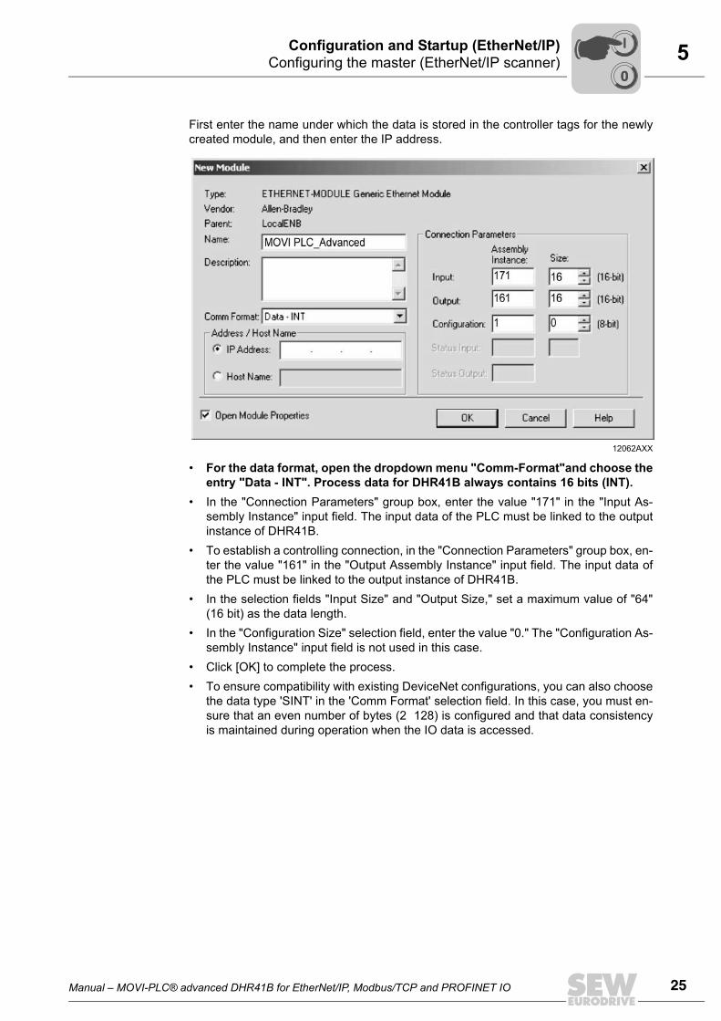
First enter the name under which the data is stored in the controller tags for the newlycreated module, and then enter the IP address.
• For the data format, open the dropdown menu "Comm-Format"and choose theentry "Data - INT". Process data for DHR41B always contains 16 bits (INT).
• In the "Connection Parameters" group box, enter the value "171" in the "Input As-sembly Instance" input field. The input data of the PLC must be linked to the outputinstance of DHR41B.
• To establish a controlling connection, in the "Connection Parameters" group box, en-ter the value "161" in the "Output Assembly Instance" input field. The input data ofthe PLC must be linked to the output instance of DHR41B.
• In the selection fields "Input Size" and "Output Size," set a maximum value of "64"(16 bit) as the data length.
• In the "Configuration Size" selection field, enter the value "0." The "Configuration As-sembly Instance" input field is not used in this case.
• Click [OK] to complete the process.• To ensure compatibility with existing DeviceNet configurations, you can also choose
the data type 'SINT' in the 'Comm Format' selection field. In this case, you must en-sure that an even number of bytes (2 128) is configured and that data consistencyis maintained during operation when the IO data is accessed.
12062AXX
00
I

26 Manual – MOVI-PLC® advanced DHR41B for EtherNet/IP, Modbus/TCP and PROFINET IO
5 Configuring the master (EtherNet/IP scanner)Configuration and Startup (EtherNet/IP)
Additional settings
The "Connection" tab page is used to set the data rate and, if required, the error re-sponse of the controller.
• The DHR41B option supports a minimum data rate (input field 'Requested Packet In-terval (RPI)') of 4 ms. Longer cycle times can be implemented without any problems.
• Click [OK]. You have now configured process data exchange with a DHR41B.
11712AXX
00
I

Manual – MOVI-PLC® advanced DHR41B for EtherNet/IP, Modbus/TCP and PROFINET IO 27
5Settings in MOVI-PLC® advanced DHR41BConfiguration and Startup (EtherNet/IP)
5.3 Settings in MOVI-PLC® advanced DHR41BThe creation of IEC programs is described in detail in the "MOVI-PLC®" manual. Thissection only describes the fieldbus-specific characteristics.
5.3.1 Process data configuration
The process data interface is normally configured by the master (scanner). It sets thenumber of process data words and the timeout interval.In the parameter tree of MOVITOOLS® MotionStudio (index 8451), the currently set val-ue is displayed in the field "PD configuration" (see following figure).
5.3.2 Status of the fieldbus interface
The function module FbusGetInfo makes the status and some display parameters of thefieldbus interface available for the IEC program and diagnostics.If there is no communication with the fieldbus master, the output Error is set to TRUE.During an active fieldbus connection, the output Done is set to TRUE, and the outputsAddress, Baud rate, Timeout and Bus type show the respective parameters as theywere set via the DIP switches of the DHR41B option or via the PLC.
12081AXX
12046AXX
00
I

28 Manual – MOVI-PLC® advanced DHR41B for EtherNet/IP, Modbus/TCP and PROFINET IO
5 Configuration examples in RSLogix 5000Configuration and Startup (EtherNet/IP)
5.4 Configuration examples in RSLogix 50005.4.1 MOVI-PLC® advanced DHR41B with 16 PD data exchange
1. Set the IP address of the DHR41B option (see section 'Setting the IP addressparameters').
2. Add MOVI-PLC® advanced DHR41B to the EtherNet/IP configuration according tochapter 5.2.
3. You can now start integration into the RSLogix project.To do so, create a controller tag with a user-defined data type to create a simple, dataconsistent interface to the process data of the DHR41B (see following figure).
The description for process input and output data of the controller tag can be madein accordance with the definition of the process data (PD) in MOVI-PLC® advancedDHR41B.
11962AXX
00
I

Manual – MOVI-PLC® advanced DHR41B for EtherNet/IP, Modbus/TCP and PROFINET IO 29
5Configuration examples in RSLogix 5000Configuration and Startup (EtherNet/IP)
4. To copy the data of MOVI-PLC® advanced DHR41B to the new data structure, a CPScommand is added at the start of the "MainRoutine" which reads the data from thecontroller tag (see following figure).
To copy the data from the new data structure to MOVI-PLC® advanced DHR41B, aCPS command is added at the end of the 'MainRoutine' (see following figure).
5. Now save the project and upload it to the PLC. The PLC is set to RUN mode.Now, the actual values can be read from MOVI-PLC® advanced DHR41B and set-points can be written.The process data should now correspond to the values displayed in the PLC Editoror in the diagnostics plug-in of the active IEC program in MOVITOOLS® MotionStu-dio. If there is no IEC program in MOVI-PLC®, you can create one as follows:
12058AXX
12059AXX
00
I

30 Manual – MOVI-PLC® advanced DHR41B for EtherNet/IP, Modbus/TCP and PROFINET IO
5 Configuration examples in RSLogix 5000Configuration and Startup (EtherNet/IP)
• Open the context menu of the PLC in MOVITOOLS® MotionStudio and run theproject wizard "Create new PLC Editor project" (see following figure).
• Use the wizard to create a new AxisControl project and upload it to MOVI-PLC®
advanced DHR41B via the menu item "Online login"• Start the loaded program via the menu item "Online start". You can now monitor
the uploaded process data under "Resources Control configuration " (PLC con-figuration). (See following figure).
12049AXX
12050AXX
00
I

Manual – MOVI-PLC® advanced DHR41B for EtherNet/IP, Modbus/TCP and PROFINET IO 31
5Configuration examples in RSLogix 5000Configuration and Startup (EtherNet/IP)
5.4.2 Access to the parameters of MOVI-PLC® advanced DHR41B
For easy read access to the parameters of MOVI-PLC® advanced DHR41B via explicitmessages and the register object, proceed as follows:1. Create a user-defined data structure "SEW_Parameter_Channel" (see following
figure).
2. Define the following controller tags (see following figure).
3. Create a rung for the 'ReadParameter' execution (see following figure).
• For contact, select the tag "ReadParameterStart"• For the Message Control, select the tag "ReadParameter"
11764AXX
11765AXX
11766AXX
00
I

32 Manual – MOVI-PLC® advanced DHR41B for EtherNet/IP, Modbus/TCP and PROFINET IO
5 Configuration examples in RSLogix 5000Configuration and Startup (EtherNet/IP)
4. Click on in the MSG command to open the 'Message Configuration' window(see following figure).
Select "CIP Generic" as "message type". Fill the other fields in the following order:A Source Element = ReadParameterRequest.IndexB SourceLength = 12C Destination = ReadParameterResponse.IndexD Class = 7hexE Instance = 1F Attribute = 4hexG Service Code = ehex
The service type is set automatically.
5. Specify the target device on the "Communication" tab. Click the [Browse] button andselect the required unit from the IO configuration (under Ethernet) in the MessagePath Browser (see following figure).
Do not select the "Connected" checkbox because both the controller and theDHR41B option permit only a limit number of connections.
11767AXX
12060AXX
00
I

Manual – MOVI-PLC® advanced DHR41B for EtherNet/IP, Modbus/TCP and PROFINET IO 33
5Configuration examples in RSLogix 5000Configuration and Startup (EtherNet/IP)
6. After downloading the changes to the PLC, the index of the parameter to be read canbe entered at ReadParameterRequest.Index. By altering ReadParameterStart to '1'the read request is executed once (see following figure).
On response to the read request, ReadParameterResponse.Index should indicatethe read index and ReadParameterResponse.Data should contain the read data. Inthis example, the timeout delay of MOVI-PLC® advanced DHR41B (index 8606) setby the scanner has been read (012Chex = 0.3 s).You can check the value in the MOVITOOLS® MotionStudio parameter tree (see fig-ure below). The tooltip displays, for example, index, subindex, factor, etc. of the pa-rameter.
11966BXX
12061AXX
00
I

34 Manual – MOVI-PLC® advanced DHR41B for EtherNet/IP, Modbus/TCP and PROFINET IO
5 Configuration examples in RSLogix 5000Configuration and Startup (EtherNet/IP)
Only few changes are required for parameter write access:• Create the controller tags (see following figure)
• Create a rung for executing the 'WriteParameter' command (see following figure).
For contact, select the tag "WriteParameterStart"For message control, select the tag "WriteParameter"
• Click on in the MSG command to open the 'Message Configuration' window(see following figure).
Fill the other fields in the following sequence:– Source Element = WriteParameterRequest.Index– Source Length = 12– Destination = WriteParameterResponse.Index– Class = 7hex– Instance = 2– Attribute = 4hex– Service Code = 10hex
11771AXX
11772AXX
11773AXX
00
I

Manual – MOVI-PLC® advanced DHR41B for EtherNet/IP, Modbus/TCP and PROFINET IO 35
5Configuration examples in RSLogix 5000Configuration and Startup (EtherNet/IP)
7. After downloading the changes to the PLC, index and value to be written into the pa-rameter can be entered at WriteParameterRequest.Index and WriteParameterRe-quest.Data. By altering WriteParameterStart to "1", the write request is executedonce (see following figure).
On response to the write request, WriteParameterResponse.Index should give thewritten index and WriteParameterResponse.Data should contain the written data. Inthis example, 22hex (33 dec) was written to index 11001 (H1).You can check the value in the MOVITOOLS® MotionStudio parameter tree or thePLC Editor. The tooltip displays, for example, index, subindex, factor, etc. of the pa-rameter.
11967BXX
00
I

36 Manual – MOVI-PLC® advanced DHR41B for EtherNet/IP, Modbus/TCP and PROFINET IO
5 Configuration examples in RSLogix 5000Configuration and Startup (EtherNet/IP)
5.4.3 Access to unit parameters of downstream units
Access to the unit parameters of a MOVITRAC® B, for example, which is connected tothe CAN 1 system bus of MOVI-PLC® advanced DHR41B is identical with the unit pa-rameter access to MOVI-PLC® advanced DHR41B itself (see chapter 5.4.2)The only difference is that Read/WriteParameterRequest.SubChannel1, for example,must be set to 3 and Read/WriteParameterRequest.SubAddress1 must be set to theSBus address of the MOVITRAC® B connected to the DHR41B option (see followingfigure).
In this example, the value 150 rpm was read from the parameter P160 Fixed setpointn11 (index 8489) of a MOVITRAC® B connected to the CAN 1 system bus of DHR41Bwith SBus address 7.For a schematic representation of the parameter access to lower-level units, refer to thechapter 'Appendix'.
11775BXX
00
I

Manual – MOVI-PLC® advanced DHR41B for EtherNet/IP, Modbus/TCP and PROFINET IO 37
6IntroductionThe Ethernet Industrial Protocol (EtherNet/IP)
6 The Ethernet Industrial Protocol (EtherNet/IP) 6.1 Introduction
The EtherNet Industrial Protocol (EtherNet/IP) is an open communication standardbased on the classic EtherNet protocols TCP/IP and UDP/IP.EtherNet/IP has been defined by the Open DeviceNet Vendor Association (ODVA) andControlNet International (CI).EtherNet/IP extends EtherNet technology to include the CIP application protocol (Com-mon Industrial Protocol). CIP is known in the field of automation engineering because itis also used for DeviceNet and ControlNet as an application protocol.
6.2 Process data exchangeUp to 64 process data words can be exchanged with an EtherNet/IP master (scanner)depending on the use of the DHR41B unit. The EtherNet/IP master (scanner) sets theprocess data length when opening the connection.In addition to a controlling 'Exclusive Owner Connection', up to two 'Listen Only Connec-tions' are available. This means the actual values of the drive can also be read out bystand-by controllers or visualization devices.If one controlling connection is already active via Modbus/TCP, an 'Exclusive OwnerConnection' cannot be activated via EtherNet/IP without a power-on reset.
Timeout behavior The timeout status is triggered by the DHR41B option. The timeout interval must be setby the EtherNet/IP master (scanner) when the connection is established. The Ether-Net/IP specification refers to a 'Requested Packet Interval (RPI)' instead of a timeout in-terval.The timeout interval displayed in the MOVITOOLS® MotionStudio parameter tree re-sults from the Requested Packet Interval (RPI) multiplied with the 'Timeout Multiplier'.This timeout interval is retained in the device when an 'Exclusive Owner Connection' isremoved, and the device switches to timeout status after the timeout interval haselapsed. The timeout status is displayed on the front of the DHR41B option by the flash-ing red L13 LED.A you can only activate the timeout delay via the bus, you must not change the value viaMOVITOOLS® MotionStudio.The timeout state causes the response programmed in the IEC program.The timeout state can be reset via EtherNet/IP as follows:• Via the reset service of the identity object (class 0x01, instance 0x01, undetermined
attribute)• By re-establishing the connection• Via the reset bit in the control word
00
I

38 Manual – MOVI-PLC® advanced DHR41B for EtherNet/IP, Modbus/TCP and PROFINET IO
6 CIP object directoryThe Ethernet Industrial Protocol (EtherNet/IP)
6.3 CIP object directoryIn the Common Industrial Protocol, all unit data can be accessed via objects. The ob-jects listed in the following table are integrated in the DHR41B option.
The meaning of the objects and a description of how to access them is given in the fol-lowing section.
Identity object • The identity object contains general information on the EtherNet/IP device.• Class code: 01hex
Class
Instance 1
Class [hex] Name
01 Identity object
02 Message Router Object
04 Assembly Object
06 Connection Manager Object
07 Register Object
0F Parameter Object
64 Vardata Object
F5 TCP/IP Interface Object
F6 EtherNet Link Object
Attri-bute
Access Name Data type
Default value [hex] Description
1 Get Revision UINT 0001 Revision 1
2 Get Max Instance UINT 0001 Maximum instance
Attri-bute
Access Name Data type Default value [hex]
Description
1 Get Vendor ID UINT 013B SEW-EURODRIVE GmbH & Co KG
2 Get Device Type
UINT 0065 Manufacturer-specific type
3 Get Product Code
UINT 0002 Product no. 2: DHR41B
4 Get
Revision STRUCT of
Revision of the identity object, depends on firmware version
Major Revision
USINT
Minor Revision
USINT
5 Get Status WORD σιεηε Table in "Coding of attribute 5 Status"
6 Get Serial Number
UDINT Unique serial number
7 Get Product Name
SHORT_ STRING
SEW-MOVIPLC ADVANCED DHR41B
Product name
00
I

Manual – MOVI-PLC® advanced DHR41B for EtherNet/IP, Modbus/TCP and PROFINET IO 39
6CIP object directoryThe Ethernet Industrial Protocol (EtherNet/IP)
• Coding of attribute 5 "Status":
• Coding of the "extended device status " (bits 4 - 7):
Supported services
Bit Name Description
0 Owned Controlling connection is active
1 - Reserved
2 Configured Configuration complete
3 - Reserved
4 - 7 Extended Device Status See table "Coding of the extended device status"
8 Minor Recoverable Fault Minor fault that can be remedied
9 Minor Unrecoverable Fault Minor fault that cannot be remedied
10 Major Recoverable Fault Major fault that cannot be remedied
11 Major Unrecoverable Fault Major fault that cannot be remedied
12 - 15 - Reserved
Value [binary] Description
0000 Unknown
0010 At least one faulty IO connection
0011 No IO connection established
0110 At least one IO connection active
Service code [hex] Service Name Class Instance
01 Get_Attributes_All X X
05 Reset - X
0E Get_Attribute_Single X X
00
I

40 Manual – MOVI-PLC® advanced DHR41B for EtherNet/IP, Modbus/TCP and PROFINET IO
6 CIP object directoryThe Ethernet Industrial Protocol (EtherNet/IP)
Message router object
• The message router object provides information on the implemented objects.• Class code: 02hex
Class
Instance 1
Supported ser-vices
Assembly object • The assembly object is used to access the DHR41B process data. IO connectionscan be created for the instances of the assembly object to exchange cyclic processdata.
• Class code: 04hex
Class
Attri-bute
Access
Name Data type Default value [hex]
Description
1 Get Revision UINT 0001 Revision 1
Attri-bute
Access
Name Data type Default value [hex] Description
1 Get Object_List STRUCT of Object list comprising:• Number of objects• List of objectsNumber UINT 0009
Classes ARRAY ofUINT
01 00 02 0004 00 06 0007 00 0F 0064 00 F5 00F6 00
2 Get Number Available
UINT 0009 Maximum number of connections
Service code [hex] Service Name Class Instance
01 Get_Attributes_All X -
0E Get_Attribute_Single X X
Attri-bute
Access
Name Data type Default value [hex] Description
1 Get Revision UINT 0002 Revision 2
2 Get Max Instance UINT 0082 Maximum instance
00
I

Manual – MOVI-PLC® advanced DHR41B for EtherNet/IP, Modbus/TCP and PROFINET IO 41
6CIP object directoryThe Ethernet Industrial Protocol (EtherNet/IP)
Instance 161 - SEW PO data range
This instance is used to access the DHR41B process output data. MOVIDRIVE® can becontrolled by only one scanner. Therefore, only one connection can be established withthis instance.
Instance 121 - "Heartbeat"
This instance is accessed when the scanner wants to establish an input only connection.No process output data is sent with this type of connection. It is used only to read pro-cess input data.
Instance 171 - SEW PI data range
This instance is used to access the DHR41B process input data. Several multicast con-nections or a point-to-point connection can be established to this instance.
Supported services
Attri-bute
Access
Name Data type Default value [hex]
Description
3 Get Data Array of BYTE
- OUTPUT assembly
Attri-bute
Access
Name Data type Default value [hex]
Description
3 Get Data Array of BYTE
- OUTPUT assemblyData size = 0
Attri-bute
Access
Name Data type Default value [hex]
Description
3 Get Data Array of BYTE
- INPUT assembly
TIPThe names "INPUT assembly" and "OUTPUT assembly" refer to the processes asseen from the networkÕs point of view. "INPUT assembly" produces data on the net-work, an "OUTPUT assembly" consumes data from the network.
Service code [hex] Service Name Class Instance 161 Instance 121 Instance 171
0E Get_Attribute_Single X X - X
00
I

42 Manual – MOVI-PLC® advanced DHR41B for EtherNet/IP, Modbus/TCP and PROFINET IO
6 CIP object directoryThe Ethernet Industrial Protocol (EtherNet/IP)
Register object • The register object is used to access an SEW parameter index.• Class code: 07hex
Class
The MOVILINK® parameter services are mapped in the nine instances of the registerobject. The "Get_Attribute_Single" and "Set_Attribute_Single" services are used for ac-cess.As the register object is designed so that INPUT objects can only be read and OUTPUTobjects can be read and written, the options listed in the following table are available foraddressing the parameter channel.
Attri-bute
Access
Name Data type Default value [hex] Description
2 Get Max Instance UINT 0009 Maximum instance
Instance INPUT/OUTPUT Resulting MOVILINK® service with
Get_Attribute_Single Set_Attribute_Single
1 INPUT READ parameter Invalid
2 OUTPUT READ WRITE parameter
3 OUTPUT READ WRITE VOLATILE parameter
4 INPUT READ MINIMUM Invalid
5 INPUT READ MAXIMUM Invalid
6 INPUT READ DEFAULT Invalid
7 INPUT READ SCALING Invalid
8 INPUT READ ATTRIBUTE Invalid
9 INPUT READ EEPROM Invalid
00
I

Manual – MOVI-PLC® advanced DHR41B for EtherNet/IP, Modbus/TCP and PROFINET IO 43
6CIP object directoryThe Ethernet Industrial Protocol (EtherNet/IP)
54185BENFigure 1: Description of the parameter channel
READ EEPROM
Get_Attribute_Single READ
READ MINIMUM
READ MAXIMUM
READ DEFAULT
READ SCALING
READ ATTRIBUTE
WRITE
WRITE VOLATILE
Get_Attribute_Single
Get_Attribute_Single
Set_Attribute_Single
Set_Attribute_Single
Get_Attribute_Single
Get_Attribute_Single
Get_Attribute_Single
Get_Attribute_Single
Get_Attribute_Single
Input
(Instance 1)
Input
(Instance 4)
Input
(Instance 5)
Input
(Instance 6)
Input
(Instance 7)
Input
(Instance 8)
Get_Attribute_SingleInput
(Instance 9)
Output
(Instance 2)
Output
(Instance 3)
EtherNet/IP SEW fieldbus profile
DPRAM
00
I

44 Manual – MOVI-PLC® advanced DHR41B for EtherNet/IP, Modbus/TCP and PROFINET IO
6 CIP object directoryThe Ethernet Industrial Protocol (EtherNet/IP)
Instance 1 - 9
The subchannels and subaddresses apply depending on the lower-level bus systemfrom MOVI-PLC® advanced DHR41B to the drives. For a schematic representation of the parameter access to lower-level units, refer to thechapter 'Appendix'.
Supported services
Attri-bute
Access Name Data type Default value [hex] Description
1 Get Bad Flag BOOL 00 0 = good / 1 = bad
2 Get Direction BOOL 0001
Input registerOutput register
3 Get Size UINT 0060 Data length in bits(96 bit = 12 byte)
4 Get/Set Data ARRAY of BITS Data in the format of the SEW parameter channel
TIPSExplanation of the attributes:• Attribute 1 indicates whether an error occurred during the previous access to the
data field.• Attribute 2 indicates the direction of the instance.• Attribute 3 indicates the data length in bits• Attribute 4 represents the parameter data. When accessing attribute 4, the SEW
parameter channel must be attached to the service telegram. The SEW parameterchannel consists of the elements listed in the following table.
Name Data type Description
Index UINT SEW unit index
Data UDINT Data (32 bit)
Subindex BYTE SEW unit subindex
Reserved BYTE Reserved (must be '0')
Subaddress 1 BYTE 0 Parameter of the MOVI-PLC® itself
1 ... e.g. SBus address of units connected to the SBus of MOVI-PLC®
Subchannel 1 BYTE 0 3 Lower-level bus system, e.g. SBus 1
Subaddress 2 BYTE Reserved (must be '0')
Subchannel 2 BYTE Reserved (must be '0')
Subchan-nel 1
Interface Value range subaddress 1
0 MOVI-PLC® itself 0
1 Inverter via DPRAM if in MDX B 0
2 EtherCAT X36 0 - 99 (the EtherCAT address is calculated from: Sub address 1 + 1001)
3 SBus1 (X33 and X26) 1 - 63
4 SBus2 (X32) 1 - 63
5 RS485_1 (X34:1/3/5 and X24) 1 - 99
6 RS485_2 (X34:2/4/6 ) 1 - 99
Service code [hex] Service Name Instance
0x0E Get_Attribute_Single X
00
I

Manual – MOVI-PLC® advanced DHR41B for EtherNet/IP, Modbus/TCP and PROFINET IO 45
6CIP object directoryThe Ethernet Industrial Protocol (EtherNet/IP)
Parameter object • In exceptional cases, you can also use the parameter object to access an SEW pa-rameter channel.
• Class code: 0Fhex
Class
The instances of the parameter object should only be used to access SEW parameterswhen the EtherNet/IP scanner does not support the option to attach user-defined datato the services "Get_Attribute_Single" and "Set_Attribute_Single."When you use the parameter object, it takes a number of steps to address a parameterindex.• First, the address of the required parameter is set in instances 1 to 4.• Next, instance 5 is used to access the parameter that is addressed in instances 1 to
4.Access to an SEW parameter index via the parameter object is complicated and proneto errors. Consequently, this process should only be used when the EtherNet/IP scannerdoes not support parameterization using the mechanisms of the register object.
Instance 1 - SEW parameter index
0x10 Set_Attribute_Single X
Service code [hex] Service Name Instance
Attri-bute
Access Name Data type Default value [hex] Description
1 Get Revision UINT 0001 Revision 1
2 Get Max Instance UINT 0005 Maximum instance
8 Get Parameter Class Descriptor
UINT 0009 Bit 0: Supports parameter instancesBit 3: Parameters are stored in a non-volatile manner
9 Get Configura-tion assem-bly interface
UINT 0000 Configuration assembly is not supported.
Attri-bute
Access Name Data type Default value [hex]
Description
1 Set Parameter Value
UINT 207A Index of the parameter
2 Get Link Path Size
USINT 00 No link is specified
3 Get Link Path Packed EPATH
00 Not used
4 Get Descriptor WORD 0000 Read/write parameter
5 Get Data type EPATH 00C7 UINT
6 Get Data Size USINT 02 Data length in bytes
00
I

46 Manual – MOVI-PLC® advanced DHR41B for EtherNet/IP, Modbus/TCP and PROFINET IO
6 CIP object directoryThe Ethernet Industrial Protocol (EtherNet/IP)
Instance 2 - SEW subindex
Instance 3 - SEW subparameter 1
Instance 4 - SEW subparameter 2
Attri-bute
Access Name Data type Default value [hex] Description
1 Set Parameter Value
UINT 0000 Low byte contains the subindex
2 Get Link Path Size
USINT 00 No link is specified
3 Get Link Path Packed EPATH
00 Not used
4 Get Descriptor WORD 0000 Read/write parameter
5 Get Data type EPATH 00C7 UINT
6 Get Data Size USINT 02 Data length in bytes
Attri-bute
Access Name Data type Default value [hex] Description
1 Set Parameter Value
UINT 0000 Low byte contains subaddress 1High byte contains subchannel 1
2 Get Link Path Size
USINT 00 No link is specified
3 Get Link Path Packed EPATH
00 Not used
4 Get Descriptor WORD 0000 Read/write parameter
5 Get Data type EPATH 00C7 UINT
6 Get Data Size USINT 02 Data length in bytes
Attri-bute
Access Name Data type Default value [hex]
Description
1 Set Parameter Value
UINT 0000 Low byte contains subaddress 2High byte contains subchannel 2
2 Get Link Path Size
USINT 00 No link is specified
3 Get Link Path Packed EPATH
00 Not used
4 Get Descriptor WORD 0000 Read/write parameter
5 Get Data type EPATH 00C7 UINT
6 Get Data Size USINT 02 Data length in bytes
00
I

Manual – MOVI-PLC® advanced DHR41B for EtherNet/IP, Modbus/TCP and PROFINET IO 47
6CIP object directoryThe Ethernet Industrial Protocol (EtherNet/IP)
Instance 5 - SEW read/write
Supported services
Attri-bute
Access Name Data type
Default value [hex]
Description
1 Set Parameter Value
UDINT The set service executes write access to the parameters addressed in instances 1 to 4.The get service executes read access to the parameters addressed in instances 1 to 4.
2 Get Link Path Size
USINT 00 No link is specified
3 Get Link Path Packed EPATH
00 Not used
4 Get Descriptor WORD 0000 Read/write parameter
5 Get Data type EPATH 00C8 UDINT
6 Get Data Size USINT 04 Data length in bytes
Service code [hex] Service Name Class Instance
0E Get_Attribute_Single X X
10 Set_Attribute_Single - X
00
I
48 Manual – MOVI-PLC® advanced DHR41B for EtherNet/IP, Modbus/TCP and PROFINET IO
6 CIP object directoryThe Ethernet Industrial Protocol (EtherNet/IP)
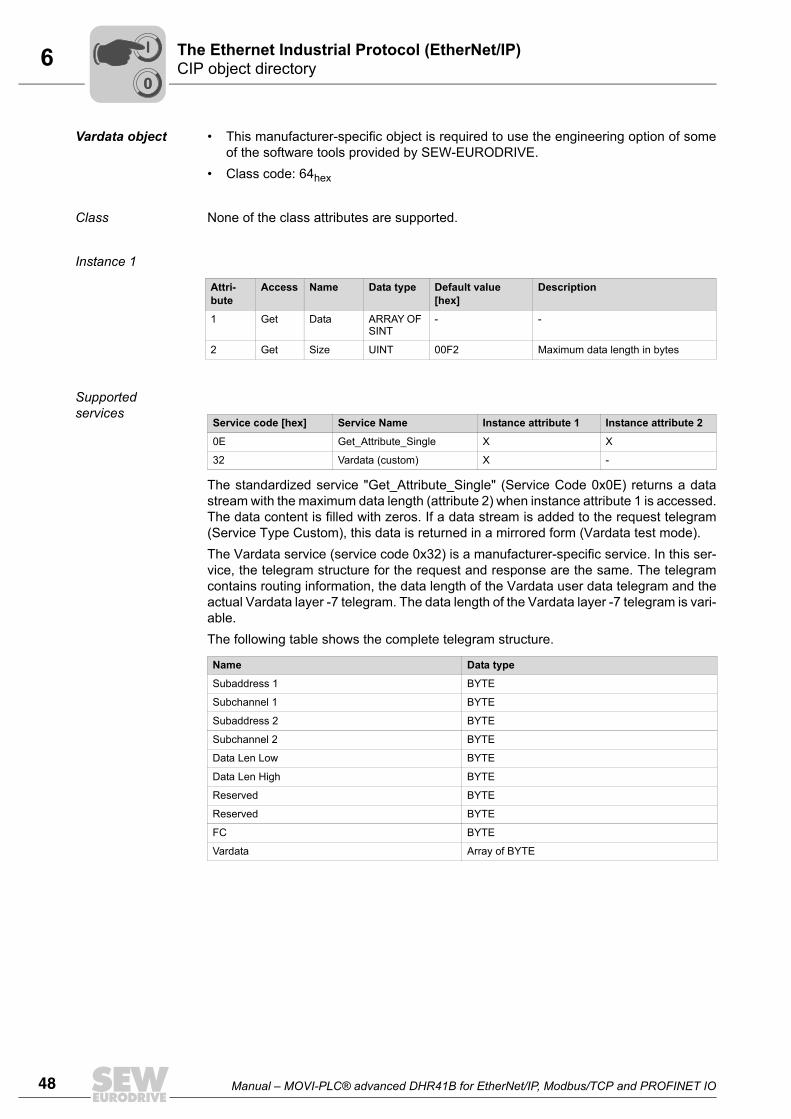
Vardata object • This manufacturer-specific object is required to use the engineering option of someof the software tools provided by SEW-EURODRIVE.
• Class code: 64hex
Class None of the class attributes are supported.
Instance 1
Supported services
The standardized service "Get_Attribute_Single" (Service Code 0x0E) returns a datastream with the maximum data length (attribute 2) when instance attribute 1 is accessed.The data content is filled with zeros. If a data stream is added to the request telegram(Service Type Custom), this data is returned in a mirrored form (Vardata test mode).The Vardata service (service code 0x32) is a manufacturer-specific service. In this ser-vice, the telegram structure for the request and response are the same. The telegramcontains routing information, the data length of the Vardata user data telegram and theactual Vardata layer -7 telegram. The data length of the Vardata layer -7 telegram is vari-able.The following table shows the complete telegram structure.
Attri-bute
Access Name Data type Default value [hex]
Description
1 Get Data ARRAY OF SINT
- -
2 Get Size UINT 00F2 Maximum data length in bytes
Service code [hex] Service Name Instance attribute 1 Instance attribute 2
0E Get_Attribute_Single X X
32 Vardata (custom) X -
Name Data type
Subaddress 1 BYTE
Subchannel 1 BYTE
Subaddress 2 BYTE
Subchannel 2 BYTE
Data Len Low BYTE
Data Len High BYTE
Reserved BYTE
Reserved BYTE
FC BYTE
Vardata Array of BYTE
00
I
Manual – MOVI-PLC® advanced DHR41B for EtherNet/IP, Modbus/TCP and PROFINET IO 49
6CIP object directoryThe Ethernet Industrial Protocol (EtherNet/IP)
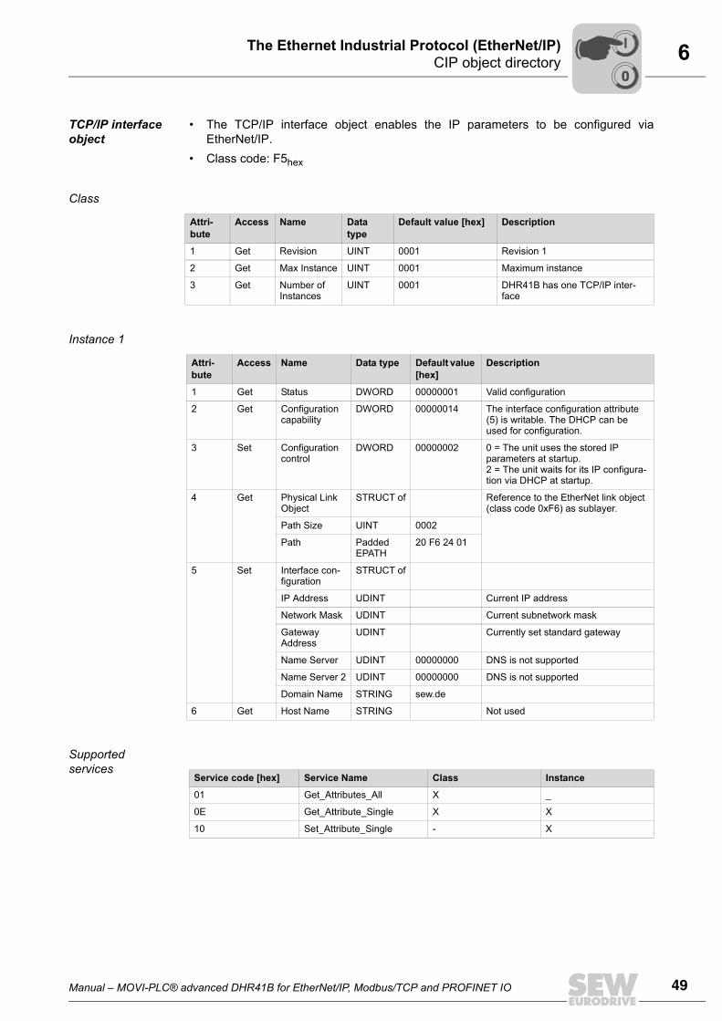
TCP/IP interface object
• The TCP/IP interface object enables the IP parameters to be configured viaEtherNet/IP.
• Class code: F5hex
Class
Instance 1
Supported services
Attri-bute
Access Name Data type
Default value [hex] Description
1 Get Revision UINT 0001 Revision 1
2 Get Max Instance UINT 0001 Maximum instance
3 Get Number of Instances
UINT 0001 DHR41B has one TCP/IP inter-face
Attri-bute
Access Name Data type Default value [hex]
Description
1 Get Status DWORD 00000001 Valid configuration
2 Get Configuration capability
DWORD 00000014 The interface configuration attribute (5) is writable. The DHCP can be used for configuration.
3 Set Configuration control
DWORD 00000002 0 = The unit uses the stored IP parameters at startup.2 = The unit waits for its IP configura-tion via DHCP at startup.
4 Get Physical Link Object
STRUCT of Reference to the EtherNet link object (class code 0xF6) as sublayer.
Path Size UINT 0002
Path Padded EPATH
20 F6 24 01
5 Set Interface con-figuration
STRUCT of
IP Address UDINT Current IP address
Network Mask UDINT Current subnetwork mask
Gateway Address
UDINT Currently set standard gateway
Name Server UDINT 00000000 DNS is not supported
Name Server 2 UDINT 00000000 DNS is not supported
Domain Name STRING sew.de
6 Get Host Name STRING Not used
Service code [hex] Service Name Class Instance
01 Get_Attributes_All X _
0E Get_Attribute_Single X X
10 Set_Attribute_Single - X
00
I

50 Manual – MOVI-PLC® advanced DHR41B for EtherNet/IP, Modbus/TCP and PROFINET IO
6 CIP object directoryThe Ethernet Industrial Protocol (EtherNet/IP)
Ethernet link object
• Information on the Ethernet communication interface is stored in the Ethernet link ob-ject.
• Class code: F6hex
Class
Instance 1 Ethernet connec-tion X30:1
Instance 2 Ethernet connec-tion X30:2
Supported services
Attri-bute
Access Name Data type Default value [hex]
Description
1 Get Revision UINT 0002 Revision 2
2 Get Max Instance UINT 0002 Maximum instance
3 Get Number of Instances
UINT 0002 DHR41B has two Ethernet interfaces
Attri-bute
Access Name Data type Default value [hex]
Description
1 Get Interface Speed
UDINT 00000064 Default value = 100 → Transmission speed in Mbit/s
2 Get Interface Flags
DWORD • Bit 0 displays the active link• Bit 1 displays full duplex mode• Bit 2 ... bit 4 signal negotiation
status• Bit 5 shows whether the manual
setting has to be reset• Bit 6 indicates a local hardware
fault
3 Get Physical Address
ARRAY of 6 USINTs
00 0F 69 xx xx xx MAC IDSEW MAC OUI: 00 0F 69
Attri-bute
Access Name Data type Default value [hex] Description
1 Get Interface Speed
UDINT 00000064 Default value = 100 → Transmission speed in Mbit/s
2 Get Interface Flags
DWORD • Bit 0 displays the active link• Bit 1 displays full duplex mode• Bit 2 bit 4 indicate the negotia-
tion status• Bit 5 shows whether the manual
setting has to be reset• Bit 6 indicates a local hardware
fault
3 Get Physical Address
ARRAY of 6 USINTs
00 0F 69 xx xx xx xx MAC IDSEW MAC OUI: 00 0F 69
Service code [hex] Service Name Class Instance
01 Get_Attributes_All X _
0E Get_Attribute_Single X X
00
I

Manual – MOVI-PLC® advanced DHR41B for EtherNet/IP, Modbus/TCP and PROFINET IO 51
6Return codes for parameter setting via explicit messagesThe Ethernet Industrial Protocol (EtherNet/IP)
6.4 Return codes for parameter setting via explicit messagesIf a parameter request via explicit messages fails, a fault code can be used to determinethe cause. An error can be generated either by the DHR41B option, by the EtherNet/IPsystem, or by a timeout.The general error code (ERR) and the additional code (EXERR) can be read out fromthe status registers of the message tags (see figure below).
Return codes of EtherNet/IP
EtherNet/IP-specific return codes are returned in the error telegram if the data format isnot maintained during the transfer or if a service is performed that has not been imple-mented. The coding of these return codes is described in the EtherNet/IP specification(see section "General error codes"). The General Error Code of a manufacturer-specificreturn code is 1Fhex.
SEW-specific return codes
The return codes that the DHR41B option or lower-level units send in the event of incor-rect parameterization are described in section 'MOVILINK®-specific return codes'. Inconjunction with EtherNet/IP, the return codes are returned in the following format. Thefollowing table shows the data format for a parameter response message as an example
In the example above, MOVILINK® error class 08 (General Error) is shown in the highbyte of the additional code. The MOVILINK® additional error code 10 (invalid index) isshown in the low byte of the additional code. This information shows that the systemtried to access a unit index that does not exist.
11937AXX
Byte offset
0 1 2 3
Function General error code Additional codeLength (words)
Additional codeword 1 (low byte)
Additional codeword 1 (high byte)
Example 1FhexVendor-specific
01hexonly low word (word 1)
10hexMOVILINK® Addi-tional Error Code
08hexMOVILINK® Error Class
00
I

52 Manual – MOVI-PLC® advanced DHR41B for EtherNet/IP, Modbus/TCP and PROFINET IO
6 Return codes for parameter setting via explicit messagesThe Ethernet Industrial Protocol (EtherNet/IP)
Timeout of the explicit mes-sages
The timeout is triggered by the DHR41B option. The timeout interval must be set by themaster after the connection has been established. The EtherNet/IP specification refersto an "Expected packet rate" rather than a timeout interval in this case. The expectedpacket rate is calculated from the timeout delay as follows:tTimeout_ExplicitMessages = 4 × tExpected_Packet_Rate_ExplicitMessages
It can be set using connection object class 5, instance 1, attribute 9. The range of valuesruns from 0 ms to 655535 ms in 5 ms steps.If there is a timeout for the explicit messages, this connection type is automaticallydropped for the explicit messages. This is the default setting for EtherNet/IP. The con-nection for these explicit messages must be re-established to communicate with thesemessages again. The timeout is not forwarded to the IEC program.
General error codes
General error code (hex)
Error name Description
00 Success Successful
01 Connection failure A connection-specific service has failed.
02 Resource unavailable The source required for performing the service is unavailable.
03 Reserved
04 Path segment error The processing node cannot interpret the 'Path segment iden-tifier' or the segment syntax.
05 Path destination unknown The 'Path' refers to an object class, object instance or a struc-tural element that is not supported by the processing node.
06 - 07 Reserved
08 Service not supported The service is not supported for the selected class/instance
09 Invalid attribute value Invalid attribute data have been sent.
0A - 0B
0C Object state conflict The selected object cannot perform the service in its current status.
0D Reserved
0E Attribute not settable It is not possible to access the selected object for writing.
10 Device state conflict The current status of the device makes it impossible to per-form the required service.
11 - 12 Reserved
13 Not enough data The length of the transferred data is too short for the service to be performed.
14 Attribute not supported The selected attribute is not supported.
15 Too much data The length of the transferred data is too long for the service to be performed.
16 Object does not exist The selected object is not implemented in the device.
17-1D Reserved
1E Embedded service error Internal processing error
1F Vendor specific error Manufacturer-specific error (see 'Fieldbus Unit Profile' man-ual)
20 Invalid parameter Invalid parameter. This error message is used when a param-eter does not satisfy the requirements of the specification and/or the requirements of the application.
21 - FF Reserved
00
I

Manual – MOVI-PLC® advanced DHR41B for EtherNet/IP, Modbus/TCP and PROFINET IO 53
6Return codes for parameter setting via explicit messagesThe Ethernet Industrial Protocol (EtherNet/IP)
MOVILINK®-spe-cific return codes
The following table shows the MOVILINK®-specific return codes (MOVILINK® 'ErrorClass' and 'Additional Code') in the event of an incorrect parameterization.
MOVILINK®
Error class Additional code Description
0x05
0x00 Unknown error
0x01 Illegal service
0x02 No response
0x03 Different address
0x04 Different type
0x05 Different index
0x06 Different service
0x07 Different channel
0x08 Different block
0x09 No scope data
0x0A Illegal length
0x0B Illegal address
0x0C Illegal pointer
0x0D Not enough memory
0x0E System error
0x0F Communication does not exist
0x10 Communication not initialized
0x11 Mouse conflict
0x12 Illegal bus
0x13 FCS error
0x14 PB init
0x15 SBUS - Illegal fragment count
0x16 SBUS - Illegal fragment type
0x17 Access denied
Not used
00
I

54 Manual – MOVI-PLC® advanced DHR41B for EtherNet/IP, Modbus/TCP and PROFINET IO
6 Return codes for parameter setting via explicit messagesThe Ethernet Industrial Protocol (EtherNet/IP)
0x08
0x00 No error
0x10 Illegal index
0x11 Not yet implemented
0x12 Read only
0x13 Parameter blocking
0x14 Setup runs
0x15 Value too large
0x16 Value too small
0x17 Required hardware does not exist
0x18 Internal error
0x19 Access only via RS485 (via X13)
0x1A Access only via RS485 (via XT)
0x1B Parameter protected
0x1C 'Controller inhibit' required
0x1D Value invalid
0x1E Setup started
0x1F Buffer overflow
0x20 'No enable' required
0x21 End of file
0x22 Communication order
0x23 'IPOS stop' required
0x24 Autosetup
0x25 Encoder nameplate error
0x29 PLC state error
MOVILINK®
Error class Additional code Description
00
I

Manual – MOVI-PLC® advanced DHR41B for EtherNet/IP, Modbus/TCP and PROFINET IO 55
7Unit description file for Modbus/TCPConfiguration and Startup (Modbus/TCP)
7 Configuration and Startup (Modbus/TCP)This section provides information about the configuration of the Modbus/TCP masterand startup of the inverter for fieldbus operation. Prerequisite is the correct connectionand setting of the IP address parameters of DHR41B in accordance with section 'As-sembly and Installation Instructions'.
7.1 Unit description file for Modbus/TCP
7.2 Configuration of the master (Modbus scanner)The first example refers to the configuration and programming of a Schneider Electriccontrol system TSX Premium P57203 using the programming software PL7 PRO. AnETY4103 is used as the Ethernet component. The information and illustrations arebased on the English version of the PL7 PRO software.
Hardware config-uration (control structure)
• Start PL7 PRO and enter the control type.• Enter the hardware configuration for the control system in the application browser un-
der STATION / Configuration / Hardware configuration.
TIPThere are no specific unit description files for Modbus/TCP.
TIP• Enter values in PL7 PRO using the keypad.• As Ethernet bus master, use components from Schneider Electric that support I/O
scanning. The Modbus/TCP interface module for SEW drives cannot be addressedvia "Peer Cop". However, Ethernet bus masters that only support "Peer Cop" canaccess the drives from the PLC program using read and write commands.
10815AXX

56 Manual – MOVI-PLC® advanced DHR41B for EtherNet/IP, Modbus/TCP and PROFINET IO
7 Configuration of the master (Modbus scanner)Configuration and Startup (Modbus/TCP)
Settings for the Ethernet component
• Double-click on the Ethernet component to open the configuration window.• If you have a non-extendable rack, enter a "1" in the "Network" input field in the
"XWAY address" section.• Enter the number of the slot that the Ethernet component is plugged into (here: 2) in
the input field "Station" in the "XWAY address" section. In this case, the XWAY ad-dress is 1.2.
• In the section "IP address configuration" select the radio button "Configured". Enterthe IP address and the network parameters in the input fields "IP address", "Subnet-work mask" and "Gateway address". If the control system is to receive the addressparameters via a DHCP server, select the radio button "Client/Server configuration"in the section "IP address configuration".
• In the "Ethernet configuration" section, select the radio button "Ethernet II".• In the "Module utilities" section, select the check box "IO Scanning".
10816AXX

Manual – MOVI-PLC® advanced DHR41B for EtherNet/IP, Modbus/TCP and PROFINET IO 57
7Configuration of the master (Modbus scanner)Configuration and Startup (Modbus/TCP)
Addressing the drive using IO scanning
• Choose the "IO Scanning" tab page. In this tab page you specify which of the stationsconnected to the Modbus are to exchange cyclical data.
• In the section "Master %MW zones" enter the control memory areas that are to beused to exchange cyclical data with the Modbus stations. You will use the memoryaddresses later in your PLC program.
• Enter the following in the "Scanned peripherals" group:– In the "IP address" input field, enter the IP address of the SEW drive.– In the "Unit ID" input field, enter the value "0".– In the "Repetitive rate" dropdown menu, enter the cycle time that is used to ad-
dress the stations.– Enter the value "4" in the input fields "RD ref.slave" and "WR ref. slave" as the
cyclical process data are available from offset 4.– In the input fields "RD count" and "WR count" enter the number of words to be
exchanged. The values must be the same in both fields. For the DHR41B option,you can enter between 1 and 64 words.
• Click on the button "Confirm " to confirm the rack configuration and the global config-uration.
• Once you have transferred your settings and started the program, the color of LEDL13 (NETWORK/STATUS) of DHR41B changes to green (see section 'Status LEDsof the DHR41B option').
10817AXX

58 Manual – MOVI-PLC® advanced DHR41B for EtherNet/IP, Modbus/TCP and PROFINET IO
7 Settings in MOVI-PLC® advanced DHR41BConfiguration and Startup (Modbus/TCP)
7.3 Settings in MOVI-PLC® advanced DHR41BThe creation of IEC programs is described in detail in the "MOVI-PLC®" manual. Thissection only describes the fieldbus-specific characteristics.
7.3.1 Process data configuration
The process data interface is normally configured by the master (scanner). The mastersets the number of process data words.In the parameter tree of MOVITOOLS® MotionStudio (index 8451), the currently set val-ue is displayed in the field "PD configuration" (see following figure).
7.3.2 Status of the fieldbus interface
The function module FbusGetInfo makes the status and some display parameters of thefieldbus interface available for the IEC program and diagnostics.If there is no communication with the fieldbus master, the output Error is set to TRUE.During an active fieldbus connection, the output Done is set to TRUE, and the outputsAddress, Baud rate, Timeout and Bus type show the respective parameters as theywere set via the DIP switches of the DHR41B option or via the PLC.
12057AXX
12046AXX

Manual – MOVI-PLC® advanced DHR41B for EtherNet/IP, Modbus/TCP and PROFINET IO 59
7Configuration examples in PL7 PROConfiguration and Startup (Modbus/TCP)
7.4 Configuration examples in PL7 PRO7.4.1 MOVI-PLC® advanced DHR41B with 16 PD data exchange
1. Set the IP address of the DHR41B option (see section 'Setting the IP address param-eters').
2. Integrate MOVI-PLC® advanced DHR41B into the configuration for I/O scanning ac-cording to section 'Configuration of the master (Modbus scanner)'.
3. Now, the integration into the PLC project can be performed.4. Create a new section in PL7 PRO in the application browser under [Station] /
[Program] / [Mast Task] / [Sections].5. In this example, the setpoints for the drive start from MW150 (see following figure).
6. Now save the project and upload it to the PLC. The PLC is set to RUN mode.Now the actual values can be read off MOVI-PLC® advanced DHR41B and setpointscan be written.The process data should now correspond to the values displayed in the PLC Editoror in the diagnostics plug-in of the active IEC program in MOVITOOLS® MotionStu-dio. If there is no IEC program in MOVI-PLC®, you can create one as follows:
10818AXX

60 Manual – MOVI-PLC® advanced DHR41B for EtherNet/IP, Modbus/TCP and PROFINET IO
7 Configuration examples in PL7 PROConfiguration and Startup (Modbus/TCP)
• Open the context menu of the PLC in MOVITOOLS® MotionStudio and run theproject wizard "New PLC Editor project" (see following figure).
• Use the wizard to create a new AxisControl project and upload it to MOVI-PLC®
advanced DHR41B via the menu item "Online login"• Start the loaded program via the menu item "Online start". You can now monitor
the uploaded process data under "Resources Control configuration " (PLC con-figuration). (See following figure).
12049AXX
12050AXX
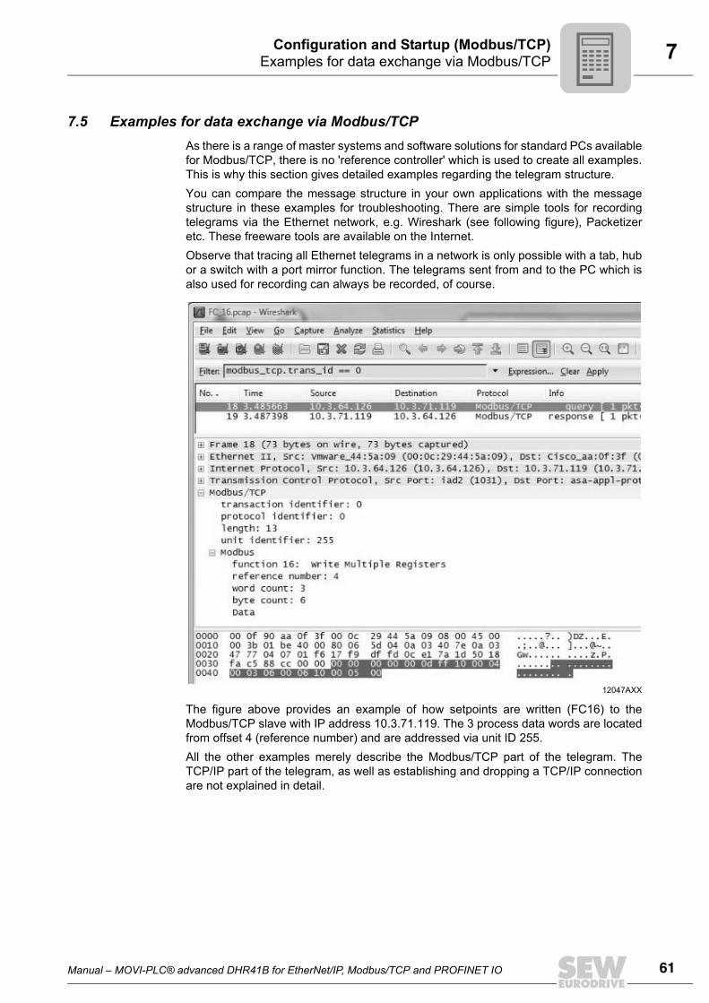
Manual – MOVI-PLC® advanced DHR41B for EtherNet/IP, Modbus/TCP and PROFINET IO 61
7Examples for data exchange via Modbus/TCPConfiguration and Startup (Modbus/TCP)
7.5 Examples for data exchange via Modbus/TCPAs there is a range of master systems and software solutions for standard PCs availablefor Modbus/TCP, there is no 'reference controller' which is used to create all examples.This is why this section gives detailed examples regarding the telegram structure.You can compare the message structure in your own applications with the messagestructure in these examples for troubleshooting. There are simple tools for recordingtelegrams via the Ethernet network, e.g. Wireshark (see following figure), Packetizeretc. These freeware tools are available on the Internet.Observe that tracing all Ethernet telegrams in a network is only possible with a tab, hubor a switch with a port mirror function. The telegrams sent from and to the PC which isalso used for recording can always be recorded, of course.
The figure above provides an example of how setpoints are written (FC16) to theModbus/TCP slave with IP address 10.3.71.119. The 3 process data words are locatedfrom offset 4 (reference number) and are addressed via unit ID 255.All the other examples merely describe the Modbus/TCP part of the telegram. TheTCP/IP part of the telegram, as well as establishing and dropping a TCP/IP connectionare not explained in detail.
12047AXX

62 Manual – MOVI-PLC® advanced DHR41B for EtherNet/IP, Modbus/TCP and PROFINET IO
7 Examples for data exchange via Modbus/TCPConfiguration and Startup (Modbus/TCP)
7.5.1 Writing and reading process data
The process data exchange can be performed either via FC3 (read) and FC16 (write),or FC23 (read and write):For writing 3 process data words (setpoints) to a Modbus/TCP slave via FC16, theTCP/IP telegram to port 502 is structured as illustrated above.
Only bytes 0-11 are returned in the response telegram of port 502 of the Modbus/TCPslave, where all values remain unchanged with the exception of byte 5. Byte 5 (low bytelength field) is corrected to value 6.
Byte Value Meaning Interpretation Help
00x00 Transaction identifier
For a detailed description, refer to Modbus/TCP specifi-cation and section 'Modbus protocol (Modbus/TCP)'
1
20x00 Protocol identifier
3
4 0x00Length field Number of bytes after byte 5:
3 (no. of PD) × 2 + 7 = 135 0x0d
6 0xFF Unit identifier Must be 0 or 255
7 ox10 Function code Service = FC16 (write register)
8 0x00Write reference number
Offset from where on the PD is located:Must always be 49 0x04
10 0x00Write word count Number of PDW (here 3):
Must for PD 1 6411 0x03
12 0x06 Write byte count Number of PDW × 2 = 6
13 0x00
Data
Process output data word 1
Data mapping and definition, see IEC program
14 0x11
15 0x22Process output data word 2
16 0x33
17 0x44Process output data word 3
18 0x55

Manual – MOVI-PLC® advanced DHR41B for EtherNet/IP, Modbus/TCP and PROFINET IO 63
7Examples for data exchange via Modbus/TCPConfiguration and Startup (Modbus/TCP)
During process data exchange via FC23, the telegram that is used to write and read 3process data words (PD) each is structured as follows.
The response telegram of the Modbus/TCP slave comprises the following data bytes.
Byte Value
Meaning Interpretation Help
00x00 Transaction identifier
For a detailed description, refer to Modbus/TCP specifi-cation and section 'Modbus protocol (Modbus/TCP)'
1
20x00 Protocol identifier
3
4 0x00Length field
Number of bytes after byte 5:3 (no. of PD) × 2 + 11 = 175 0x11
6 0xFF Unit identifier Must be 0 or 255
7 0x10 Function code Service = FC23 (read + write reg-ister)
8 0x00Read reference number
Offset from where the PD is located:Must always be 49 0x04
10 0x00Read word count Number of PDW (here 3):
Must for PD 1 6411 0x03
12 0x00Write reference number
Offset from where the PD is located:Must always be 413 0x04
14 0x00Write word count Number of PDW (here 3):
see read word count15 0x03
16 0x06 Write byte count Number of PDW × 2 = 6
17 0x00
Data
Process output data word 1
Data mapping and definition, see IEC program
18 0x11
19 0x22Process output data word 2
20 0x33
21 0x44Process output data word 3
22 0x55
Byte Value
Meaning Interpretation Help
00x00 Transaction identifier
For a detailed description, refer to Modbus/TCP speci-fication and section 'Modbus protocol (Modbus/TCP)'
1
20x00 Protocol identifier
3
4 0x00Length field
Number of bytes after byte 5:3 (no. of PD) × 2 + 3 = 95 0x09
6 0xFF Unit identifier Must be 0 or 255
7 0x17 Function code Service = FC23 (read + write reg-ister)
8 0x06 Write byte count Number of PDW × 2 = 6
9 0x00
Data
Process input data word 1
Data mapping and defini-tion, see IEC program
10 0xAA
11 0xBBProcess input data word 2
12 0xCC
13 0xDDProcess input data word 3
14 0xEE

64 Manual – MOVI-PLC® advanced DHR41B for EtherNet/IP, Modbus/TCP and PROFINET IO
7 Examples for data exchange via Modbus/TCPConfiguration and Startup (Modbus/TCP)
7.5.2 Parameter access
FC23 is suitable for the parameter access via the MOVILINK® parameter channel as itis possible to realize the request to the MOVILINK® service and the collection of the re-sponse in one Modbus/TCP service.For read purposes, the TCP/IP telegram is structured as follows.
Byte Value
Meaning Interpretation Help
00x00 Transaction identifier
For a detailed description, refer to Modbus/TCP specifi-cation and section 'Modbus protocol (Modbus/TCP)'
1
20x00 Protocol identifier
3
4 0x00Length field
Number of bytes after byte 5:Must be 19 for MOVILINK®
5 0x13
6 0x00 Unit identifier 1)
1) The unit identifier 0 and 0xFF is used to access the parameters of DHR41B directly. For other values, therequest is passed on to a lower-level unit. The assignment of the unit identifier to the downstream units onthe system buses is determined via the routing table of the DHR41B control configuration. This allows pa-rameter access for inverters that are connected via a DHR41B unit without any restrictions. See the 'Ap-pendix' for a schematic representation of parameter access to lower-level units.
7 0x17 Function code Service = FC23 (read + write reg-ister)
8 0x02Read reference number
Offset where the MOVILINK® parameter channel starts:Must always be 512.9 0x00
10 0x00Read word count Must always be 4 for the MOV-
ILINK® parameter channel.11 0x04
12 0x02Write reference number
Offset where the MOVILINK® parameter channel starts:Must always be 512.13 0x00
14 0x00Write word count Must always be 4 for the MOV-
ILINK® parameter channel.15 0x04
16 0x08 Write byte count 8 bytes MOVILINK®
17 0x31
Data:MOVILINK® parameter channel
Administration byte: 0x31 = read
Data mapping and definition, see IEC program and SEW unit profile
18 0x00 Parameter subindex
19 0x20 Parameter index:0x206c = 8300 = Firmware part number20 0x6C
21 0x00 Parameter value Irrelevant for read service22 0x00
23 0x00
24 0x00

Manual – MOVI-PLC® advanced DHR41B for EtherNet/IP, Modbus/TCP and PROFINET IO 65
7Examples for data exchange via Modbus/TCPConfiguration and Startup (Modbus/TCP)
The response telegram receives the response to the MOVILINK® read service.
Byte Value
Meaning Interpretation Help
00x00 Transaction identifier
For a detailed description, refer to Modbus/TCP specifi-cation and section 'Modbus protocol (Modbus/TCP)'
1
20x00 Protocol identifier
3
4 0x00Length field
Number of bytes after byte 5:Must be 11 for MOVILINK®
5 0x11
6 0x00 Unit identifier 1)
1) The unit identifier 0 and 0xFF is used to access the parameters of DHR41B directly. For other values, therequest is passed on to a lower-level unit. The assignment of the unit identifier to the downstream units onthe system buses is determined via the routing table of the DHR41B control configuration. This allows pa-rameter access for inverters that are connected via a DHR41B unit without any restrictions. See the 'Ap-pendix' for a schematic representation of parameter access to lower-level units.
7 0x17 Function code Service = FC23 (read + write reg-ister)
8 0x02 Read reference number 8 bytes MOVILINK®
17 0x31
Data:MOVILINK® parameter channel
Administration byte: 0x31 = read
Data mapping and definition, see unit setting and SEW unit profile
18 0x00 Parameter subindex
19 0x20 Parameter index:0x206c = 8300 = Firmware part number20 0x6C
21 0x00 The parameter value 0xA82e5b0d corresponds to firm-ware part number 28216102.53.22 0x00
23 0x00
24 0x00

66 Manual – MOVI-PLC® advanced DHR41B for EtherNet/IP, Modbus/TCP and PROFINET IO
8 IntroductionThe Modbus Protocol (Modbus/TCP)
8 The Modbus Protocol (Modbus/TCP)8.1 Introduction
Modbus/TCP is an open protocol based on TCP/IP. It was one of the first protocol typesto become standard in industrial Ethernet interfaces for process data transfer.Modbus frames are exchanged via the TCP/IP port 502. Every master IP address is ac-cepted. Modbus exclusively uses the coding 'BIG ENDIAN' (Motorola data format or highbyte first).Access via 'Peer Cop' is not possible. Make sure that the bus master supports 'IO scan-ning'.Modbus/TCP is integrated into the DHR41B option as of firmware version .11.
8.1.1 Mapping and addressing
The logic Modbus address scope is 64 k words and is addressed via the reference num-ber (offset). Four different tables can be in the address scope:• Binary inputs (RO)• Binary outputs (RW)• Input register (RO)• Output register (RW)The tables can be separated or overlapping.
The DHR41B option provides the following data areas:• For the process data transfer, there is a table that allows for write access (for setpoint
values) as well as for read access (for actual values).This table starts at offset 4 and ends at offset 0FFhex. It contains the 1 64 cyclicallytransferred process data words.
• The process data output words from the controller are also saved in another table. Itallows for one or several additional clients (e.g. visualization) to read the current set-point values.This table starts at offset 104hex and ends at offset 1FFhex.
• A third table is provided for the parameter access.This table starts at offset 200hex, ends at offset 2FFhex and contains 4 words of theMOVILINK® parameter channel (see 'Fieldbus Unit Profile' manual).
• The remaining address scope from offset 400hex to FFFFhex is reserved and mustnot be addressed.The data word at offset 219hex (8606dec) is a special case, it allows for writing (andreading) the timeout monitoring time.
TIPFor Schneider Electric control systems:The address range often starts with 40001hex, which corresponds to an offset with thevalue '0'.
00
I

Manual – MOVI-PLC® advanced DHR41B for EtherNet/IP, Modbus/TCP and PROFINET IO 67
8IntroductionThe Modbus Protocol (Modbus/TCP)
8.1.2 Services (function codes)
For process data exchange, parameter data exchange and unit identification, theDHR41B option provides 4 FC.. services (Function Codes).• FC 3 Read Holding Registers• FC16 Write Multiple Registers• FC23 Read/Write Multiple Registers• FC43 Read Device IdentificationThe FC3 and FC16 services allow reading or writing of one or more registers. FC23 al-lows a register block to be read and written simultaneously. FC43 can be used for a unitidentification by reading out the identity parameters.
8.1.3 Access
The implemented registers and possible services (function codes) for data exchangeare summarized in the following table.
Meaning when
Offset (hex) Reading Writing Access Comment
0 - 3 - - - Reserved
4 - FF Process input data (actual val-ues)
Process output data (setpoint values)
FC3, FC16, FC23
0 - 64 words
100 - 103 - - - Reserved
104 - 1FF Process output data (setpoint val-ues)
- FC3 For reading the setpoint values by a client other than the controlling one
200 - 2FF Result acyclical parameter chan-nel
Request acyclical parameter channel
FC3, FC16, FC23
4 words
300 - FFFF - - - Reserved
Special case: 219E (8606dec)
Fieldbus timeout interval, read value
Fieldbus timeout interval, write value
FC3, FC16 Parameter P819: 16-bit value, tim-eout interval in ms
00
I

68 Manual – MOVI-PLC® advanced DHR41B for EtherNet/IP, Modbus/TCP and PROFINET IO
8 Protocol structureThe Modbus Protocol (Modbus/TCP)
8.2 Protocol structureThe Modbus protocol consists of a header and function code data. The header is thesame for all request/response telegrams and error messages (exceptions). Dependingon the function code, a different number of data is attached to the header (see followingpicture).
8.2.1 HeaderThe protocol bytes of the header are described in the following table:
• The slave simply copies the transaction identifier (byte 0 and 1). It can help the mas-ter to identify related actions.
• The protocol identifier (byte 2 and 3) must always be '0'.• The length bytes (byte 4 and 5) specify the number of bytes occurring in the length
field. As the maximum telegram length is 255 bytes, the 'upper byte' must be '0'.• The unit identifier (byte 6) can be used for distinguishing between several connected
stations (e.g. bridges or gateways). It has the function of a subaddress that is onlyused for parameter access in SEW units. The process data are always mapped tothe unit that is addressed via the unit identifier 0 or FFhex.
• The 7 bytes of the header are followed by the function code and the data.
64064AXX
MBAP Header
Transaction-ID Protocol-ID Length (1+1+N) UI-D
Function Code-Data
FC N Data
Byte Designation Meaning
0Transaction identifier Often 0, is simply copied by the server (slave)
1
2Protocol identifier 0
3
4 Length field (upper byte) 0
5 Length field (lower byte) Number of function codes data bytes + 1 (unit identifier)
6 Unit identifier (slave address) This is the slave address. In order to access the DHR41B process data, it must be set to '0' (0x00) or 255 (0xFF).The following address assignments apply to the parameter chan-nel access (Offset 200 - 203hex):• 0 or 254 for parameters of the DHR41B• 1 253 for parameters of a lower-level unit connected to
DHR41B. The assignment of unit identifier to the units on the system buses is determined via the routing table on the DHR41B memory card (see section '"Appendix"').
7 Function code Requested service
8 ... Data Data depending on requested service
00
I

Manual – MOVI-PLC® advanced DHR41B for EtherNet/IP, Modbus/TCP and PROFINET IO 69
8Protocol structureThe Modbus Protocol (Modbus/TCP)
8.2.2 Service FC3 Read holding registers
With the service FC3 Read holding registers, you can read a variable number of regis-ters (see following figure).
Example Request:
Response:
Exception:
64065AXX
MBAP Header Function Code-Data(FC03)
FC(0x03)
Read Address Read WordCountT- ID (0x00) Prot-ID (0x00) Length (1+5) UI-D
Byte Designation Meaning/permitted values
0 - 6 MBAP header See chapter 'Header'.
7 Function code Requested service: 3 (Read Holding Register)
8 Reference number (high) Offset
9 Reference number (low) Offset
10 Word count (high) Number of words (register)
11 Word count (low) Number of words (register)
Byte Designation Meaning/permitted values
0 - 6 MBAP header See chapter 'Header'.
7 Function code Service: 3 (Read Holding Register)
8 Byte count Number of following bytes
9.... Data 2 - ... Data bytes depending on the length
Byte Designation Meaning/permitted values
0 - 6 MBAP header See chapter 'Header'.
7 Function code 83hex
8 Exception code Fault code
00
I

70 Manual – MOVI-PLC® advanced DHR41B for EtherNet/IP, Modbus/TCP and PROFINET IO
8 Protocol structureThe Modbus Protocol (Modbus/TCP)
8.2.3 Service FC16 Write multiple registers
With the service FC16 Write Multiple Registers you can write a variable number of reg-isters (see following figure).
Example Request:
Response:
Exception:
64066AXX
MBAP Header Function Code-Data(FC16)
FC(0x10)
T- ID (0x00) Prot-ID (0x00)UI-D
(0x00)
Length
(1+6+N) Write Address Write WordCountBytes
(N)Write Data
(1 ... N)
Byte Designation Meaning/permitted values
0 - 6 MBAP header See chapter 'Header'.
7 Function code Requested service: 16 (Write Multiple Registers)
8 Reference number (high) Offset
9 Reference number (low) Offset
10 Word count (high) Number of words (register)
11 Word count (low) Number of words (register)
12 Byte count 2* Word count
13 ... Register values 2 - ... Data bytes depending on the length
Byte Designation Meaning/permitted values
0 - 6 MBAP header See chapter 'Header'.
7 Function code Service: 16 (Write Multiple Registers)
8 Reference number (high) Offset
9 Reference number (low) Offset
10 Word count (high) Number of words (register)
11 Word count (low) Number of words (register)
Byte Designation Meaning/permitted values
0 - 6 MBAP header See chapter 'Header'.
7 Function code 90hex
8 Exception code Fault code
00
I

Manual – MOVI-PLC® advanced DHR41B for EtherNet/IP, Modbus/TCP and PROFINET IO 71
8Protocol structureThe Modbus Protocol (Modbus/TCP)
8.2.4 Service FC23 Read/write multiple registers
With the service FC23 Read/write multiple registers, you can simultaneously write andread a variable number of registers. The write access is carried out first. Preferably, thisservice is used for the process data (see following picture).
Example Request:
Response:
Exception:
64071AXX
MBAP Header Function Code-Data (FC23)
Bytes (N) (1...N)
FC(0x17)
T- ID (0x00) Prot-ID (0x00) UI-DLength(1+10+N)
Read Address Write Address Write DataReadWordCount
Write WordCount
Byte Designation Meaning/permitted values
0 - 6 MBAP header See chapter 'Header'.
7 Function code Requested service: 23 (Read/Write Multiple Registers)
8 Read reference number (high)
Offset
9 Read reference number (low)
Offset
10 Read word count (high) Number of words (register) always 0
11 Read word count (low) Number of words (register)
12 Write reference number (high)
Offset
13 Write reference number (low) Offset
14 Write word count (high) Number of words (register) always 0
15 Write word count (low) Number of words (register)
16 Write byte count 2* Word count
17 ... Write register values 2 - ... Data bytes depending on the length
Byte Designation Meaning/permitted values
0 - 6 MBAP header See chapter 'Header'.
7 Function code Service: 23 (Read/Write Multiple Registers)
8 Byte count Number of following bytes
9 Data 2 - ... Data bytes depending on the length
Byte Designation Meaning/permitted values
0 - 6 MBAP header See chapter 'Header'.
7 Function code 97hex
8 Exception code Fault code
00
I

72 Manual – MOVI-PLC® advanced DHR41B for EtherNet/IP, Modbus/TCP and PROFINET IO
8 Protocol structureThe Modbus Protocol (Modbus/TCP)
8.2.5 Service FC43 Read device identification
The service FC43 Read device identifications is also referred to as MEI ('Modbus En-capsulated Interface Transport'). It can tunnel services and method calls. The serviceRead Device Identification is tunneled with the MEI-Type 0x0E. According to theModbus specifications, there are 3 blocks (Basic, Regular and Extended) that can beread. The DHR41B option supports the Basic and Regular blocks (conformity level 02).The entire block is always read (streaming). This means that values 01 and 02 are per-mitted in the Read device ID code. The Object ID must be zero. The response is not frag-mented.
Example Request:
Response:
Exception:
Byte Designation Meaning/permitted values
0 - 6 MBAP header See chapter 'Header'.
7 Function code Requested service: 43 (Read Device Identification)
8 MEI type 0x0E
9 Read device ID code 01 or 02
10 Object ID 0
Byte Designation Meaning/permitted values
0 - 6 MBAP header See chapter 'Header'.
7 Function code Service: 43 (Read Device Identification)
8 MEI type 0x0E
9 Read device ID code 01 or 02
10 Conformity level 02
11 More follows 0
12 Next object ID 0
13 Number of objects e.g. 3
14 Object ID
15 Object length
16 Object value
17 ....
Byte Designation Meaning/permitted values
0 - 6 MBAP header See chapter 'Header'.
7 Function code 43hex
8 Exception code Fault code
00
I

Manual – MOVI-PLC® advanced DHR41B for EtherNet/IP, Modbus/TCP and PROFINET IO 73
8Connection managementThe Modbus Protocol (Modbus/TCP)
Objects DHR41B
8.3 Connection managementUp to 8 simultaneous Modbus connections are possible, max. one of which has writeaccess to the process data area (controlling connection).Connections that are no longer used must be dropped by the master. If a ninth connec-tion is to be established and the slave detects a connection that is no longer active, it issevered on one side by the slave because it assumes that the associated master is nolonger active. If there are 8 active connections, the attempt to establish a ninth connec-tion is cancelled (socket is closed on the server). Connections 1 - 8 operate indepen-dently of each other. There is no prioritization. Only one controlling connection that canchange process data is permitted.If a controlling connection has already been established via EtherNet/IP, you cannot es-tablish another controlling connection via Modbus/TCP. The slave can at least bufferone frame with maximum Modbus length on receipt or transmission.
8.3.1 Sending process output data (requesting a controlling connection)
Sending process output data is only permitted if the connection already is a controllingconnection or if there is no controlling connection. If the unit accepts the connection, ittransfers the process output data to the process data image or transmits the processdata to a lower-level station (gateway operation). As long as this connection is activated,no other master can change the process output data (PO data).
Object ID Name Type M/O Category Value (example)
0x00 VendorName
ASCII String
Mandatory Basic
"SEW-EURODRIVE"
0x01 ProductCode "SEW MOVI-PLC ADVANCED DHR41B"
0x02 MajorMinorRevisions "823 568 0.10" (example)
0x03 VendorUrl
Optional Regular
"www.sew.de"
0x04 ProductName "SEW MOVI-PLC ADVANCED"
0x05 ModelName "DHR41B"
00
I

74 Manual – MOVI-PLC® advanced DHR41B for EtherNet/IP, Modbus/TCP and PROFINET IO
8 Connection managementThe Modbus Protocol (Modbus/TCP)
8.3.2 Dropping connections
A connection is deleted from the internal connection list if• The 'keep alive' time has elapsed and the server no longer receives a response, or• The socket reports a fault• The connection to the client has been dropped
If it was a controlling connection, another controlling connection can be established.If there are no permitted PO data sent within the timeout interval, a fieldbus timeoutis triggered.
The default keep-alive time is 10 seconds. If there is a controlling connection with thetimeout interval > 5 s, the keep-alive time is increased to 2 × timeout interval.In the event of a cable break or a socket fault of a controlling connection, the fieldbustimeout in the unit will be displayed once the timeout interval has elapsed. Then a newcontrolling connection can be established.
8.3.3 Timeout monitoring
The timeout monitoring time can be set in the range of 0 to 650 s in steps of 10 ms.• 0 s and 650 s means: Timeout monitoring is deactivated• 10 ms - 649.09 s means: Timeout monitoring is activated
The timeout interval can be set via:• Register object 219Ehex (8606dec)• Parameter access to index 8606 via register object 200hex 203hex
• Parameters in the parameter tree of MOVITOOLS® MotionStudio The timeout monitoring is triggered when a controlling connection is activated. The field-bus driver cyclically checks whether the last PO data update was received within the tim-eout interval.If the timeout monitoring is deactivated by setting the timeout interval to 0 or 65000, nofieldbus timeout is detected. This also applies when the controlling connection isdropped.In the event of a timeout, the timeout response is executed as programmed in the IECprogram.A change to the timeout interval (writing on index 8606) is activated after a re-boot.
00
I

Manual – MOVI-PLC® advanced DHR41B for EtherNet/IP, Modbus/TCP and PROFINET IO 75
8Parameter access via Modbus/TCPThe Modbus Protocol (Modbus/TCP)
8.4 Parameter access via Modbus/TCPA parameter access via the MOVILINK® parameter channel in registers 200hex 203hexvia Modbus/TCP requires the services FC3, FC16 or FC23 (write and read access).Write access is used for storing acyclic requests in the corresponding registers. Readservices read the responses from the same registers. This method corresponds to the alternative concept according to the Modbus specifica-tions (appendix A) 'Network Messaging Specification for the MODBUS/TCP Protocol:Version 1.1".
8.4.1 Procedure with FC16 and FC3
The respective error code is generated if a write access is incorrect (see section 'Errorcodes (exception codes)'). In this way, the write services are already processed bysending a Write request (FC16), and the service confirmation can be carried out by eval-uating the Write response. Later on, the master will send a Read Request (FC03) in or-der to read out the values that have now been written into the register.
8.4.2 Procedure with FC23
With FC23, the result is returned directly in the response.
64072AEN
Master /Modbus client
Slave /Modbus server
FC16 Request withacyclical command
FC3 Request toread acyclical result
FC16 Response,write access o.k.
FC3 Response withacyclical result
64073AEN
Master /Modbus client
Slave /Modbus server
FC23 Request withacyclical command
FC3 Response withacyclical result
00
I

76 Manual – MOVI-PLC® advanced DHR41B for EtherNet/IP, Modbus/TCP and PROFINET IO
8 Parameter access via Modbus/TCPThe Modbus Protocol (Modbus/TCP)
8.4.3 Protocol structure
Or:
* The unit identifier (UI-D) is used in gateway operation to map registers 200hex 203hexto the lower-level stations, see section 'Header'.
The description of the MOVILINK® parameter data (8 bytes) and their mapping to reg-isters 200hex 203hex is described in section 'MOVILINK® parameter channel'.
64067AXX
Byte-Count(0x8)
MOVILINK®
Parameter-Data
Write
Request:
Read
Request:
MBAP Header Function Code-Data
FC(0x10)
T- ID (0x00) Prot-ID (0x00)UI-D
(*)
Length
(1+6+8)Write Address
(0x200)
Write WordCount(0x04)
Byte-Count(0x8)
MOVILINK®
Parameter-DataFC
(0x03)T- ID (0x00) Prot-ID (0x00)
UI-D
(*)
Length
(1+6+8)Write Address
(0x200)
Write WordCount(0x04)
Write
Response:
Read
Response:
FC(0x10)
T- ID (0x00) Prot-ID (0x00)UI-D
(*)
Length
(1+5)Write Address
(0x200)
Write WordCount
(0)
FC(0x03)
T- ID (0x00) Prot-ID (0x00)UI-D
(*)
Length
(1+5)Read Address
(0x200)
Read WordCount(0x04)
64165AXX
Byte-Count(0x8)
Write/Read
Request:
Write/Read
Response:
FC(0x17)
T- ID (0x00) Prot-ID (0x00)UI-D
(*)
Length
(1+10+8)Read Address Write Address
(0x200) (0x200)
ReadWordCount(0x04)
Write WordCount(0x04)
Byte-Count(0x8)
MOVILINK®
Parameter-DataFC
(0x17)T- ID (0x00) Prot-ID (0x00)
UI-D
(*)
Length
(1+6+8)Read Address
(0x200)
ReadWordCount(0x04)
MOVILINK®
Parameter-Data
00
I

Manual – MOVI-PLC® advanced DHR41B for EtherNet/IP, Modbus/TCP and PROFINET IO 77
8Parameter access via Modbus/TCPThe Modbus Protocol (Modbus/TCP)
8.4.4 MOVILINK® parameter channel
The following table shows the structure of the MOVILINK® acyclic parameter channel.It contains 8 bytes.
You can access the parameter channel with FC3, FC16 and FC23. You can inform theparameter channel of the task in the administration byte using a write access. The taskitself is a MOVILINK® service such as Write, Write Volatile or Read. The result can beread with a read access. Refer to the "MOVIDRIVE® Fieldbus Unit Profile and Parame-ter List" documentation for information on the structure of the parameter channel.In this example, the MOVILINK® parameter channel is used to request 500 ms to be writ-ten to the fieldbus timeout interval:• Offset 200 = 3200hex (administration = write 4 bytes / subindex = 0)• Offset 201 = 219Ehex (Index = 8606)• Offset 202 = 0(Data high)• Offset 203 = 01F4hex (data low = 500)
Offset 200hex 200hex 201hex 201hex 202hex 202hex 203hex 203hex
Meaning Adminis-tration
Subin-dex
Index high
Index low
MSB data
Data Data LSB data
Comment Adminis-tration
Parameter index + subindex 4-byte data
Example:Writing field-bus timeout (index 8606)
32hex 00hex 21hex 9Ehex 00hex 00hex 01hex F4hex
00
I

78 Manual – MOVI-PLC® advanced DHR41B for EtherNet/IP, Modbus/TCP and PROFINET IO
8 Fault codes (exception codes)The Modbus Protocol (Modbus/TCP)
8.5 Fault codes (exception codes)If an error occurs when processing a function code, the Modbus client is informed in anexception response. The following exception codes can be reported by SEW devices:
Exception code (hex)
Name Meaning
01 ILLEGAL FUNCTION The function code transferred to the request is not sup-ported by the slave unit.
02 ILLEGAL DATA ADDRESS You have entered an invalid data address for the access to the Modbus slave. This can be due to the following reasons:• Invalid start address when accessing the register of
the Modbus slave (not available or the function code cannot be used on this address)
• Invalid start address/length combination• No symmetric access with read/write• Wrong object ID (on access via FC43)
03 ILLEGAL DATA VALUE A part of the data field of the Modbus request contains a value invalid for the Modbus slave. This can be due to the following reasons:• The 'Word count' contains an invalid value (smaller
than 1 or larger than 125)• The received PDU length is too short or too long
(depending on the specified 'word count')• Internal fault while reading/writing the process data
04 SLAVE DEVICE FAILURE Fault while accessing MOVILINK® parameters (e.g. internal timeout)
06 SLAVE DEVICE BUSY There is already a controlling connection (either via another Modbus controller or another fieldbus system)
0A GATEWAY PATH UNAVAILABLE The data cannot be transferred to a subsystem.
00
I

Manual – MOVI-PLC® advanced DHR41B for EtherNet/IP, Modbus/TCP and PROFINET IO 79
9Diagnostic sequenceFault Diagnostics for Operation on EtherNet/IP and Modbus/TCP
9 Fault Diagnostics for Operation on EtherNet/IP and Modbus/TCP9.1 Diagnostic sequence
The diagnostic procedures described in the following section demonstrate the integra-tion of the DHR41B option into an Ethernet network and the error analysis method forthe following problems:• The MOVI-PLC® advanced DHR41B controller is not integrated properly in the
EtherNet/IP or Modbus/TCP network• The master (scanner) cannot specify any process data.For detailed information about programming the DHR41B unit, refer to the "MOVI-PLC®"advanced DHE41B/DHF41B/DHR41B Controller" manualFor more diagnostic information, refer to the online status display in the EtherNet/IPmaster (scanner), in the Modbus/TCP master and the corresponding online help.
Step 1: Checking the status LEDs of DHR41B and the DIP switch settings
The possible DIP switch settings are described in chapter "Setting the DIP switches".For detailed information on the individual LED statuses, refer to chapter "Status LEDsof the DHR41B option". The following table lists the resulting unit statuses for commu-nication via X30-1 and X30-2 and possible causes. An 'X' indicates that the state of therespective LED is not relevant.
In order to check and set the IP parameters, you can proceed according to section'Setting IP address parameters' or use MOVITOOLS® MotionStudio.The PING and IPCONFIG commands that you can enter via the DOS console on yourPC are further tools for checking the communication via Ethernet.
LED
L14 MODULE STATUS
L13 NETWORK STATUS
Operating status
Cause
Off Off Off No voltage supply.
Red Red Reset DHR41B is in reset status.
Red X Error Internal DHR41B fault.
Flashing green
Off IP-Stack starting
If DHCP is active, the DHR41B remains in this state until assigned an IP address.
Flashing red
Red IP conflict IP address conflict if the same IP address is used by another station in the network.
Flashing green/red
Flashing green/red
LED test All LED conditions are briefly activated.
Flashing green
Flashing green
Application starting
All functions of the DHR41B (e. g. process data and connec-tions to the master) are now active.
Green Flashing green
Operational DHR41B is active on the fieldbus but without a controlling connection to the master.
Green Green Connected There is a controlling connection to a master.
Green Flashing red Timeout A previously controlling connection is in timeout state.

80 Manual – MOVI-PLC® advanced DHR41B for EtherNet/IP, Modbus/TCP and PROFINET IO
9 Diagnostic sequenceFault Diagnostics for Operation on EtherNet/IP and Modbus/TCP
Step 2: Check the status LED and the status display on the master (scanner)
To do so, use the documentation of the controller or master module.Should there be no working EtherNet/IP or Modbus/TCP master yet, you can use anSEW master simulator for testing or starting up the DHR41B option. The latest versionof the master simulator is available on the SEW website.You can use the SEW master simulator to exchange process or parameter data withEtherNet/IP or Modbus/TCP profile with an SEW fieldbus interface.
Step 3: Fault diagnostics
If DHR41B is in the 'Connected' status, data exchange between master (scanner) andslave is active. If the data is not transferred to the IEC application of MOVI-PLC® ad-vanced DHR41B via EtherNet/IP or Modbus/TCP correctly, the following steps will as-sist you in finding the cause for the problem.
A Are the correct values for the process data words displayed in the PLC Editor?If yes, continue with F.
B Is the process data exchange activated in the scanner (master)?C Is the process data written to the correct location in the scanner? Check the tags and
scanner mapping.D Is the PLC in RUN mode or does active forcing overwrite the transfer of the normal
process data words?E If the PLC is not sending data to the DHR41B, please refer to the documentation of
the PLC manufacturer for support.F Are the process data words being used correctly in the IEC program?G Which status is displayed in the IEC application for the communication interface via
the FBusGetInfo module (see chapter "Settings in MOVI-PLC® advancedDHR41B")?

Manual – MOVI-PLC® advanced DHR41B for EtherNet/IP, Modbus/TCP and PROFINET IO 81
10Configuring the PROFINET IO controllerPROFINET IO Configuration
10 PROFINET IO Configuration10.1 Configuring the PROFINET IO controller
The following paragraphs describe the configuration of MOVI-PLC® advanced DHR41Bwith PROFINET interface. The configuration will be explained using the example of theSIMATIC STEP 7 configuration software and a SIMATIC CPU 315F-2 PN/DP.
10.1.1 Installing the GSD file
Proceed as follows to install the GSD file:1. Start STEP 7 HW Config and select the [Install new GSD file] menu item in the
[Extras] menu.A window is displayed.
2. Click on [Browse] and select the following file:"GSDML-V2.1-DHR41B-UFR41B-JJJJMMTT.xml" (JJJJMMTT represents the date)
3. Click on [OK] to confirm your selection.4. You will find the PROFINET IO interface for MOVI-PLC® advanced DHR41B via
[PROFINET IO]/[Other field units]/[Drives]/[SEW]/[DHR41B/UFR41B] in the hard-ware catalog.2 files are available for configuring the DHR41B option:• DHR41B V1.0
for controllers that support the PROFINET IO topology detection• DHR41B V1.0 ALT
for controllers that do not support the PROFINET IO topology detection
TIPThe latest GSD(ML) file version is also available for download on the SEW website(www.sew-eurodrive.de) in the "Software" section.
00
I

82 Manual – MOVI-PLC® advanced DHR41B for EtherNet/IP, Modbus/TCP and PROFINET IO
10 Configuring the PROFINET IO controllerPROFINET IO Configuration
10.1.2 Assigning a PROFINET device name
Proceed as follows to assign the PROFINET device name:1. Select [ETHERNET]/[Edit ETHERNET station] from the [Target system] menu in
STEP 7 HW Config.The following window opens:
2. Click on the [Browse] [1] button in the 'ETHERNET stations' group. You receive anoverview of all PROFINET IO stations that you can reach online with your configura-tion tool.
64630AXX
[1] [Browse] button
[2] " IP address" input field
[3] "Subnet mask" input field
[4] "Router address" input field
[5] "Assign IP Configuration" button
[6] "Device name" input field
[7] "Assign name" button
[8] [Close] button
[1]
[2]
[3]
[5]
[6]
[8]
[4]
[7]
00
I

Manual – MOVI-PLC® advanced DHR41B for EtherNet/IP, Modbus/TCP and PROFINET IO 83
10Configuring the PROFINET IO controllerPROFINET IO Configuration
3. Choose the required station. The SEW station appears under unit type. The default device name is 'PNETDevice-Name' and must be changed appropriately. Several MOVI-PLC® advanced DHR41Bcan be distinguished from each other by their displayed MAC address. A label withthe MAC address is attached to the DHR41B option.
4. Enter the device name in the 'Device name' input field [6] and click the [Assign name]button [7]. The device name can have up to 255 characters. The device name is transferred toand saved in the station. Click on [Reset] to reset the device name of MOVI-PLC® advanced DHR41B online.This requires a restart of DHR41B.
5. Specify an IP address [2] and a subnet mask [3] as well as a router address [4], ifrequired.Click the [Assign IP configuration] button [5].
6. Check whether the settings have been applied by once again clicking the [Browse]button [1].
7. Click the [Close] button [8].
TIPThe IO controller must not yet be in a cyclic data transmission with the IO devices.
00
I

84 Manual – MOVI-PLC® advanced DHR41B for EtherNet/IP, Modbus/TCP and PROFINET IO
10 Configuring the PROFINET connection for MOVI-PLC® advanced DHR41BPROFINET IO Configuration
10.2 Configuring the PROFINET connection for MOVI-PLC® advanced DHR41B10.2.1 Creating a new project
Proceed as follows to create a new project: 1. Start the SIMATIC Manager and create a new project.
Select your control type and add the required modules. The following modules makesense: • OB82 module: This module makes sure that the controller does not trigger a
'STOP' in the event of so-called diagnostic alarms. • OB86 module: This module indicates the failure of decentralized peripherals. • OB122 module:This module is addressed if the controller cannot access data of
a station of the decentralized periphery. This can occur, for example, when MOVI-PLC® advanced DHR41B is ready for operation later than the control system.
2. Start STEP 7 HW Config and select the PROFINET IO slot in the control rack.3. Add a PROFINET IO system by right-clicking the context menu with your mouse. 4. Specify an IP address for the PROFINET IO controller when doing this. 5. Add a new PROFINET subsystem using the [ETHERNET] button.6. Open [PROFINET IO]/[Additional field devices]/[Drives]/[SEW]/[DHR41B/UFR41B]
in the hardware catalog.2 entries are available for the DHR41B option:• DHR41B V1.0
for controllers that support the PROFINET IO topology detection• DHR41B V1.0 ALT
for controllers that do not support the PROFINET IO topology detection
00
I

Manual – MOVI-PLC® advanced DHR41B for EtherNet/IP, Modbus/TCP and PROFINET IO 85
10Configuring the PROFINET connection for MOVI-PLC® advanced DHR41BPROFINET IO Configuration
7. Move the entry 'DHR41B/UFR41B' to the PROFINET IO system with the mouse andassign a PROFINET station name. This name must correspond to the PROFINETdevice name specified in MOVI-PLC® advanced DHR41B.
8. Enter the IO and periphery addresses in slot 2 and save the configuration.The slot model is used for configuration with PROFINET. Each slot is assigned to aMOVI-PLC® fieldbus interface. The following structure is used:
The default configuration 'Slot not used' must not be modified. Slot 1 is reserved forfuture PROFIsafe applications. Slots 2 17 can be assigned process data channels. The maximum process datawidth is 64 words.
9. Add data exchange with the new units to your user program. Process data transferis consistent. SFC14 and SFC15 can be used to transfer process data.
12098AXX
00
I

86 Manual – MOVI-PLC® advanced DHR41B for EtherNet/IP, Modbus/TCP and PROFINET IO
10 Configuring the PROFINET connection for MOVI-PLC® advanced DHR41BPROFINET IO Configuration
10.2.2 Configuring a station
When the individual slots are configured, the new station has to be configured with fur-ther settings. Proceed as follows to configure a station: 1. Double-click on the unit symbol of the new station.
The following window opens:
2. Enter the device name assigned before in the 'Device name' input field [2] on the'General' tab [1]. Note that the name is case-sensitive.
3. Click on the [ETHERNET] button [3] in the 'Station/PN IO system' group in order toenter the previously assigned IP address.
64631AXX
[1] "General" tab
[2] "Device name" input field
[3] [ETHERNET] button
[1]
[2]
[3]
00
I

Manual – MOVI-PLC® advanced DHR41B for EtherNet/IP, Modbus/TCP and PROFINET IO 87
10Configuring the PROFINET connection for MOVI-PLC® advanced DHR41BPROFINET IO Configuration
4. Double-click on the 'ETHERNET interface' slot in order to set the station’s updatetime.The following window opens:
5. On the 'IO cycle' tab [1], set the update time [2] for the station to update its processdata. As a gateway, MOVI-PLC® advanced DHR41B supports a minimum update time of4 ms.
64632AXX
[1] "IO Cycle" tab page
[2] "Update time" selection field
[1]
[2]
00
I

88 Manual – MOVI-PLC® advanced DHR41B for EtherNet/IP, Modbus/TCP and PROFINET IO
10 PROFINET configuration with topology detectionPROFINET IO Configuration
10.3 PROFINET configuration with topology detection10.3.1 Introduction
The PROFINET technology detection allows for projecting and monitoring the structureof the network with the PROFINET IO controller in addition to the PROFINET IO devic-es. The so-called 'Physical device (PHDEV)' is the starting point for the configuration. ThePDEV is a model for the ETHERNET interface and can be found in slot 0 of the config-uration with an 'ETHERNET interface' subslot and one subslot for each ETHERNETport. The visible ETHERNET ports can be connected to the configuration tool. The result isan image of the desired ETHERNET routing for the plant. This image is stored in thePROFINET IO controller.In order to be able to determine the real plant topology, the PROFINET IO devices mustsupport the so-called LLDP protocol. The PROFINET IO devices exchange informationwith the neighboring PROFINET IO devices via LLDP. Via LLDP, each PROFINET IOdevice cyclically sends information about its own PROFINET device name and portnumber. The neighboring unit receives and stores this information. Now a PROFINETIO controller can read the stored information from the PROFINET IO devices to deter-mine the real plant topology. By comparing the projected topology with the real topology, you can detect any missingor incorrectly wired PROFINET IO devices and localize them in the plant. Apart from cabling you can still determine the transmission characteristics for the ports.For example, you can set an 'Auto-negotiation' port to '100 Mbit full duplex'. The settingswill be monitored. SNMP as a protocol for network diagnostics extends the topology detection with stan-dard diagnostics mechanisms from the IT area.
00
I

Manual – MOVI-PLC® advanced DHR41B for EtherNet/IP, Modbus/TCP and PROFINET IO 89
10PROFINET configuration with topology detectionPROFINET IO Configuration
10.3.2 Configuring the PROFINET topology
The configuration procedure for a PROFINET topology will be described using the ex-ample of SIMATIC STEP 7. There are various approaches for configuration inSIMATIC STEP 7. This example will focus on one approach. 1. In STEP 7 HW Config, import the PROFINET devices from the hardware catalog into
the PROFINET network as usual. Make sure that the PROFINET IO controller supports topology detection. The con-troller manufacturer will provide according information.The hardware catalog contains several entries for each SEW interface marked as dif-ferent versions. An entry marked with 'ALT' does not support the PROFINET IO to-pology detection.
2. Right-click on the 'PROFINET IO system' and select 'PROFINET IO topology' fromthe context menu.The 'Topology editor' window is displayed.
12099AXX
00
I

90 Manual – MOVI-PLC® advanced DHR41B for EtherNet/IP, Modbus/TCP and PROFINET IO
10 PROFINET configuration with topology detectionPROFINET IO Configuration
3. Select the 'Offline/online comparison' tab [1].
4. Determine the online topology by clicking [Start] [2].5. Make sure that the determined topology complies with your requirements by clicking
on the plus symbol [3] in the online topology and checking the partner port.The following units are displayed in this example:• 2 SEW units (MOVIDRIVE®, MOVI-PLC® advanced DHR41B)• One controller• One switch The switch does not support topology and is highlighted white. The remainingPROFINET IO devices are not linked yet and are thus highlighted yellow.
6. In order to apply the determined online topology to the configuration port by port,right-click on a port. In the context menu, select 'Apply port interconnection'. Repeatthis procedure for all ports of the devices until the lists are green.
64633AXX
[1] 'Offline/online comparison' tab
[2] [Start] button
[3] Plus/minus symbol
[1]
[3]
[2]
00
I

Manual – MOVI-PLC® advanced DHR41B for EtherNet/IP, Modbus/TCP and PROFINET IO 91
10PROFINET configuration with topology detectionPROFINET IO Configuration
10.3.3 Changing the port properties
The two ETHERNET ports of the PROFINET interface are set to 'Automatic setup' bydefault. Observe the following for this default setup: • Auto-negotiation and auto-crossover are activated in this setup. • The baud rate and the duplex mode are configured automatically.• The neighboring port must also be set to 'Automatic setup'.• You can use patch or crossover cables.
You may set a port to '100 Mbit/s full duplex'. Observe the following for this setting: • This setting must also be made for the port of the neighboring unit, otherwise it would
work with 100 Mbit/s half duplex. • If auto-crossover is deactivated, you have to use cross cables.
Proceed as follows to set a port to '100 Mbit/s full duplex': 1. Select a unit in STEP 7 HW Config.2. Select the desired port on slot 0.3. Right-click on the port and select 'Object properties' from the context menu.
A window is displayed.
00
I

92 Manual – MOVI-PLC® advanced DHR41B for EtherNet/IP, Modbus/TCP and PROFINET IO
10 PROFINET configuration with topology detectionPROFINET IO Configuration
4. Select the 'Options' tab [1].
5. From the 'Transmission medium/duplex' [2] list, select 'TP/ITP with 100 Mbit/s full du-plex'.
6. Deactivate the 'Auto-negotiation/auto-crossover' checkbox [3].
64634AXX
[1] 'Options' tab
[2] 'Transmission medium/duplex' selection list
[3] 'Auto-negotiation/auto-crossover' checkbox
[2]
[1]
[3]
00
I

Manual – MOVI-PLC® advanced DHR41B for EtherNet/IP, Modbus/TCP and PROFINET IO 93
10PROFINET configuration with topology detectionPROFINET IO Configuration
10.3.4 Topology diagnostics
Topology errors are reported to the PROFINET IO controller as diagnostics alarms. Inthe event of an error, the EXTF-LED of the PROFINET IO controller is lit. The error isalso indicated by a red cross [1] in STEP 7 HW Config.
Possible causes:• ETHERNET ports mixed up• Wrong port property settings• Units cannot be addressed
Proceed as follows to display information on an error: 1. Select the unit or the respective slot.2. Right-click and select 'Module status' from the context menu.
A window is displayed.3. Select the 'Communication diagnostics' tab.
64635AXX
[1]
[1]
[1]
[1] 'Red cross' symbol for error
00
I

94 Manual – MOVI-PLC® advanced DHR41B for EtherNet/IP, Modbus/TCP and PROFINET IO
10 PROFINET configuration with topology detectionPROFINET IO Configuration
10.3.5 Port statistics
Proceed as follows to display the port statistics for an ETHERNET port in STEP 7 HWConfig: 1. Click the 'ONLINE ? OFFLINE' symbol to switch to the 'Online' communication mode.2. Select a unit.3. Select the desired port on slot 0.4. Right-click and select 'Module status' from the context menu.
A window is displayed.Select the 'Statistics' tab [1].The following view is displayed:
The following statistic values can be displayed:• Dropped received packets no resources indicates the number of valid
ETHERNET packets dropped on receipt. A large number of dropped valid packetssuggests a high load on the bus system. In this case, try to reduce the utilization byespecially reducing the number of broadcast and multicast telegrams and reducingthe IO cycle or the number of PROFINET units in a line if required.
64345AXX
[1] 'Statistics' tab
[1]
00
I

Manual – MOVI-PLC® advanced DHR41B for EtherNet/IP, Modbus/TCP and PROFINET IO 95
10PROFINET configuration with topology detectionPROFINET IO Configuration
• Bad received packets indicates the number of faulty ETHERNET packets. A highnumber suggests a bus fault. In this case, check the cabling and shielding of the net-work.
• Received octets indicates the number of received packets.• Dropped sent packets – no resources indicates the number of valid ETHERNET
packets dropped on dispatch. A large number of dropped valid packets suggests ahigh load on the bus system. In this case, try to reduce the utilization by especiallyreducing the number of broadcast and multicast telegrams and reducing the IO cycleor the number of PROFINET units in a line if required.
• Bad sent packets – transmission collisions indicates the number of ETHERNETpackets dropped due to collisions. There should be no collisions in a switched net-work.
• Sent Octets indicates the number of sent packets.
00
I

96 Manual – MOVI-PLC® advanced DHR41B for EtherNet/IP, Modbus/TCP and PROFINET IO
10 PROFINET diagnostics alarmsPROFINET IO Configuration
10.4 PROFINET diagnostics alarms10.4.1 Switching on the diagnostic alarms
The PROFINET interface supports diagnostic alarms in the event of a unit fault. Thesediagnostic alarms are deactivated by default. Proceed as follows to activate the diagnos-tics alarms in STEP 7 HW Config:1. Highlight slot 0. 2. Right-click on it and select 'Object properties ...' from the context menu.
A window is displayed.3. Select the "Parameters" tab [1].4. In 'Activate diagnostics alarms' [2], set the alarms to 'ON'
64646AXX
[1] "Parameters" tab
[2] 'Activate diagnostics alarms' node
[1]
[2]
00
I

Manual – MOVI-PLC® advanced DHR41B for EtherNet/IP, Modbus/TCP and PROFINET IO 97
10PROFINET diagnostics alarmsPROFINET IO Configuration
10.4.2 Determining the cause of a fault
A fault in the function unit belonging to the plug-in module causes a diagnostic alarm tobe sent to the controller as an 'incoming event'. Proceed as follows to determine a fault in STEP 7 HW Config:1. Click the 'ONLINE <-> OFFLINE' symbol to switch to the 'Online' communication
mode.2. Mark the symbol of the SEW PROFINET interface.3. Right-click on it and select 'Component status' from the context menu.
A window is displayed.
4. Select the 'IO device diagnostics' tab [1].5. Click on [Display] to receive detailed information on the fault.
After resetting the fault, a so-called 'ongoing event' is sent to the controller. The SFLED of the CPU goes out and no more faults are displayed in the component status.
64647AXX
[1] 'IO device diagnostics' tab
[1]
00
I

98 Manual – MOVI-PLC® advanced DHR41B for EtherNet/IP, Modbus/TCP and PROFINET IO
11 Process data exchange with MOVI-PLC® advanced DHR41BOperating Behavior (PROFINET IO)
11 Operating Behavior (PROFINET IO)This section describes the basic behavior of the MOVI-PLC® advanced DHR41B con-troller when operated on the PROFIBUS system.
11.1 Process data exchange with MOVI-PLC® advanced DHR41BMOVI-PLC® advanced DHR41B is controlled via the process data channel which is upto 2 × 32 I/O words in length. These process data words are mapped in the I/O or pe-ripheral area of the MOVI-PLC® advanced DHR41B controller, for example, when ahigher-level PLC is used as the DP master. As a result, the process data words can beaddressed in the usual manner.
Control example for Simatic S7
Process data exchange with MOVI-PLC® advanced DHR41B is controlled usingSIMATIC S7 in accordance with the selected process data configuration either directlyusing load and transfer commands or by means of special system functions, SFC 14DPRD_DAT and SFC15 DPWR_DAT.
STEP7 sample program
In this example, the MOVI-PLC® advanced DHR41B controller is configured with theprocess data configuration 10 PD on input addresses PEW512... and output addressesPAW512....A data block DB3 is created with about 50 data words.
64648AXXFigure 2: Mapping PROFINET data in the PLC address range
[1] Address range of the higher-level PLC
PI1 - PI64 Process input dataPO1 - PO64 Process output data
PW160
PW160
PA 3
PE 3
PA 2
PE 2
PA 1
PE 1
PW158
PW158
PW156
PW156
PA 1
PE 1 PE 2
PA 2
PE 3
PA 3
PE 64
PA 64
[2]
DHR41B
22
01
X30-1
X30-2
L14
L13
ON
1
2
3
X38
L12
L11
00
I

Manual – MOVI-PLC® advanced DHR41B for EtherNet/IP, Modbus/TCP and PROFINET IO 99
11Process data exchange with MOVI-PLC® advanced DHR41BOperating Behavior (PROFINET IO)
When SFC14 is called, the process input data is copied to data block DB3, data words0 to 18. When SFC15 is called after the control program has been processed, the pro-cess output data are copied from data words 20 38 to the output address POW 512 ...Note the length information in bytes for the RECORD parameter. The length informationmust correspond to the configured length.Refer to the online help for STEP7 for further information about the system functions.
//Start of cyclical program processing in OB1BEGINNETWORKTITLE = Copy PI data from the DHR41B control card to DB3, words 0...18CALL SFC 14 (DPRD_DAT) //Read DP slave record LADDR := W#16#240 //Input address 512 RET_VAL:= MW 30 //Result in flag word 30 RECORD := P#DB3.DBX 0.0 BYTE 20 //Pointer
NETWORKTITLE =PLC program with drive application// PLC program uses the process data in DB3 for data exchange// with the DHR41B control card
L DB3.DBW 0 //Load PE1L DB3.DBW 2 //Load PE2L DB3.DBW 4 //Load PE3// etc.
L W#16#0006T DB3.DBW 20 //Write 6hex to PO1L 1500T DB3.DBW 22 //Write 1500dec to PO2L W#16#0000T DB3.DBW 24 //Write 0hex to PO3// etc.
NETWORKTITLE = Copy PO data from DB3, words 20...38 to the DHR41B control cardCALL SFC 15 (DPWR_DAT) //Write DP slave record LADDR := W#16#200 //Output address 512 = 200hex RECORD := P#DB3.DBX 20.0 BYTE 20 //Pointer to DB/DW RET_VAL:= MW 32 //Result in flag word 32
TIP• This program example is a special and free service that demonstrates only the ba-
sic principles of generating a PLC program as a non-binding sample. SEW is notliable for the contents of the sample program.
• You can download S7 sample projects from the SEW homepage (http://www.sew-eurodrive.de) under 'Software'.
00
I

100 Manual – MOVI-PLC® advanced DHR41B for EtherNet/IP, Modbus/TCP and PROFINET IO
11 Settings in MOVI-PLC® advanced DHR41BOperating Behavior (PROFINET IO)
The following figure shows the corresponding configuration for the MOVI-PLC® ad-vanced DHR41B control card in the hardware configuration of STEP7.
11.2 Settings in MOVI-PLC® advanced DHR41BThe creation of IEC programs is described in detail in the "MOVI-PLC®" manual. Thissection only describes the fieldbus-specific characteristics.
11.2.1 Status of the PROFINET fieldbus interface
The function module FbusGetInfo makes the status and some display parameters of thefieldbus interface available for the IEC program and diagnostics.
12100AXX
12046AXX
00
I

Manual – MOVI-PLC® advanced DHR41B for EtherNet/IP, Modbus/TCP and PROFINET IO 101
11Settings in MOVI-PLC® advanced DHR41BOperating Behavior (PROFINET IO)
If there is no communication with the fieldbus master, the output Error is set to TRUE.During an active fieldbus connection, the output Done is set to TRUE, and the outputsAddress, Baud rate, Timeout and Bus type show the respective parameters as theywere set via the DIP switches of the DHR41B option or via the PLC.
Checking the process data communication
Now the actual values can be read off MOVI-PLC® advanced DHR41B and setpointscan be written.The process data should now correspond to the values displayed in the PLC Editor orin the diagnostics plug-in of the active IEC program in MOVITOOLS® MotionStudio.If there is no IEC program in MOVI-PLC®, you can create one as follows:• Open the context menu of the PLC in MOVITOOLS® MotionStudio and run the proj-
ect wizard "New PLC Editor project" (see following figure).
• Use the wizard to create a new AxisControl project and upload it to MOVI-PLC®
advanced DHR41B via the menu item "Online login"
12049AXX
00
I

102 Manual – MOVI-PLC® advanced DHR41B for EtherNet/IP, Modbus/TCP and PROFINET IO
11 Parameterization via PROFIdrive data record 47Operating Behavior (PROFINET IO)
• Start the loaded program via the menu item "Online start". You can now monitor theuploaded process data under Resources Control configuration (PLC configuration).(See following figure).
11.3 Parameterization via PROFIdrive data record 47
11.3.1 Introduction to PROFINET data records
With "Read Record" and "Write Record", PROFINET offers acyclic services that can beused to transfer parameter data between PROFINET controller (master) and aPROFINET device (slave). Via UDP (User Datagram Protocol), the priority of this dataexchange is lower than the priority of the process data exchange.
12050AXX
TIPThe S7 sample project "MOVILINK® parameter channel" can be used for this param-eter channel. You can download it from the SEW homepage (http://www.sew-euro-drive.de) under 'Software'.
00
I

Manual – MOVI-PLC® advanced DHR41B for EtherNet/IP, Modbus/TCP and PROFINET IO 103
11Parameterization via PROFIdrive data record 47Operating Behavior (PROFINET IO)
The user data transported via an acyclic PROFINET service is grouped in a dataset.Each dataset is clearly addressed by the following characteristics:• API• Slot number• Subslot number• IndexThe structure of dataset 47 is used for the parameter exchange with SEW-EURODRIVEPROFINET units. The structure of data record 47 is specified in the PROFIdrive profiledrive technology of the PROFIBUS user organization as of V4.0 as PROFINET param-eter channel. Different procedures for accessing parameter data of the SEW-EURODRIVE PROFINET unit are provided via this parameter channel.
62204AXX
PO
PROFINETController
PIRead/Write Record
SEWPROFINET
Device
00
I

104 Manual – MOVI-PLC® advanced DHR41B for EtherNet/IP, Modbus/TCP and PROFINET IO
11 Parameterization via PROFIdrive data record 47Operating Behavior (PROFINET IO)
Characteristics of the SEW-EURODRIVE PROFINET devices
The SEW-EURODRIVE PROFINET units that support acyclic Read Record and WriteRecord services all have the same communication characteristics. The units are basi-cally controlled via a PROFINET controller with cyclic process data. Additionally, thiscontroller (usually a PLC) can set the parameters for the SEW-EURODRIVE PROFINETunit via Read Record and Write Record.
62205AXX
Drive System
Read / Write Record
PROFINET
Cyclic IN/Out
Pa
ram
ete
r B
uff
er
1
Parameter BufferProcess Data
PD
SE
W P
RO
FIN
ET
Inte
rfa
ce
PROFINET
Controller
00
I

Manual – MOVI-PLC® advanced DHR41B for EtherNet/IP, Modbus/TCP and PROFINET IO 105
11Parameterization via PROFIdrive data record 47Operating Behavior (PROFINET IO)
11.3.2 Structure of the PROFINET parameter channel
Generally, the parameter setting of the devices to the PROFIdrive-Base Mode Parame-ter Access of profile version 4.0 is implemented via data record 47. The Request ID entryis used to distinguish between parameter access based on PROFIdrive profile or viaSEW-MOVILINK® services. The following table shows the possible codes of the individ-ual elements. The data record structure is the same for PROFIdrive and MOVILINK®
access.
The following MOVILINK® services are supported:• 8-byte MOVILINK® parameter channel with all the services supported by the station
such as– READ parameter– WRITE parameter– WRITE parameter volatile– etc.
62206AXX
Field Data type Values
Unsigned8 0x00 Reserved0x01 - 0xFF
Request ID Unsigned8 0x40 SEW MOVILINK® service0x41 SEW Data Transport
Response ID Unsigned8 Response (+):0x00 Reserved0x40 SEW MOVILINK® service (+)0x41 SEW Data Transport
Response (-):0xC0 SEW MOVILINK® service (-)0x41 SEW Data Transport
Unsigned8 0x00 - 0xFF Number of axes 0 - 255
No. of parameters Unsigned8 0x01 - 0x13 1 - 19 DWORDs (240 DP-V1 data bytes)
Attribute Unsigned8 For SEW-MOVILINK® (Request ID = 0x40):0x00 No service0x10 READ Parameter0x20 WRITE Parameter0x40 Read Minimum0x50 Read Maximum0x60 Read Default0x80 Read Attribute0x90 Read EEPROM0xA0 - 0xF0 reserviert
SEW Data Transport:0x10 Wert
No. of Elements Unsigned8 0x00 For parameters that are not indexed0x01 - 0x75 Quantity 1 - 117
Parameter Number Unsigned16 0x0000 - 0xFFFF MOVILINK® parameter index
Subindex Unsigned16 0x0000
Format Unsigned8 0x43 Double word0x44 Error
No. of Values Unsigned8 0x00 - 0xEA Quantity 0 - 234
Error Value Unsigned16 0x0080 + MOVILINK® Additional Code LowFor SEW MOVILINK® 16 bit error value
READ/WRITEPROFIdrive
Parameter Channel
DS47SEW MOVILINK®
Record
00
I

106 Manual – MOVI-PLC® advanced DHR41B for EtherNet/IP, Modbus/TCP and PROFINET IO
11 Parameterization via PROFIdrive data record 47Operating Behavior (PROFINET IO)
11.3.3 Parameter setting procedure via data record 47
Parameter access takes place with the combination of the WRITE RECORD and READRECORD PROFINET services. The parameter setting order is transferred to the IO de-vice using the WRITE.req, Then it is processed internally.The controller now sends a READ.req to pick up the parameter setting response. Thedevice sends a positive response READ.res. The user data now contain the parametersetting response of the parameter setting order that was previously sent with WRITE.req(see the following figure). This mechanism applies to a PROFINET controller.
62208AXXFigure 3: Telegram sequence for parameter access via Read/Write Record
Controller PROFINET SEW-Device
WRITE.req DS47
with data (parameter request)
READ.req DS47
without data
WRITE.res
without data
READ.res(+)
with data (parameter response)
Parameter
Request
Parameter
Processing
Parameter
Response
Parameter
Request
Parameter
Response
00
I

Manual – MOVI-PLC® advanced DHR41B for EtherNet/IP, Modbus/TCP and PROFINET IO 107
11Parameterization via PROFIdrive data record 47Operating Behavior (PROFINET IO)
11.3.4 Controller processing sequence
If the bus cycles are very short, the request for the parameter response arrives beforethe SEW device has concluded the parameter access in the device. This means that theresponse data from the SEW device is not yet available. In this state, the device delaysthe response to the Read Record Request.
62209AEN
Send Write.request
with parameter data
Send Read.request
Check Write.
response
Write.response
negative
Write.response
positive
Parameter transfer
aborted with ERROR
Read.response
negative orYes
No
Parameter transfer
ok, data available
timeout
00
I

108 Manual – MOVI-PLC® advanced DHR41B for EtherNet/IP, Modbus/TCP and PROFINET IO
11 Parameterization via PROFIdrive data record 47Operating Behavior (PROFINET IO)
11.3.5 Addressing downstream inverters
The structure of the DS47 dataset defines an axis element. This element is used toreach multi-axis drives that are operated via one PROFINET interface. The axis elementaddresses one of the units connected via the PROFINET interface.
Parameter access to downstream stations
Setting Axis = 0 enables access to the parameters of the MOVI-PLC® advancedDHR41B controller. The PLC Editor offers a routing table. This routing table assigns'Axis settings' to the downstream inverters.Example: An inverter connected to CAN 1 of MOVI-PLC® advanced DHR41B with SBusaddress 1 is addressed with Axis =1.
See the 'Appendix' for a schematic representation of parameter access to lower-levelunits.
64803AXX
C1-Master
Acyclic DP-V1
C2 Services
Acyclic DP-V1C2 Services
Axis = 0
Axis = 0
Axis = 0
Cyclic OUT Data
Cyclic IN Data
PD
PDPROFIBUS DP-V1
Acyclic DP-V1
C1 Services
C2-Master C2-Master
EURODRIVE
EURODRIVE
MOVIDRIVE®B
SBus
MOVITRAC®B
DHR41B
MOVIAXIS®
Axis = 1
Axis = 2
Axis = 3
P881=1 P881=2 SBus-Address=3
DHR41B
22
01
2
4
6
X34
X35
X36
X30-1
X30-2
X37
XM
1
3
5
1
2
3
1
2
3
1
2
3
1
2
3
X3
2X
33
2
4
6
1
3
58
10
7
9
X31
S1
3
4
2
1
L14
L13
L10
L9
L8
L7
T1
L6
L5
L4
L3
L2
L1
ON
1
2
3
X38
L12
L11
00
I

Manual – MOVI-PLC® advanced DHR41B for EtherNet/IP, Modbus/TCP and PROFINET IO 109
11Parameterization via PROFIdrive data record 47Operating Behavior (PROFINET IO)
11.3.6 MOVILINK® parameter requests
The MOVILINK® parameter channel of the SEW inverter is directly mapped in the struc-ture of data record 47. The request ID 0x40 (SEW MOVILINK® service) is used for theexchange of MOVILINK® parameter setting orders. Parameter access with MOVILINK®
services usually takes place according to the structure described below. The typical tele-gram sequence is used for data record 47.Request ID: 0x40 SEW MOVILINK® service
The actual service is defined by the data record element Attribute in the MOVILINK® pa-rameter channel. The high nibble of the element corresponds to the MOVILINK® servicecode.
Example for read-ing a parameter via MOVILINK®
The following tables give an example of the structure of the WRITE.request andREAD.response user data for reading an individual parameter via the MOVILINK®
parameter channel.
Sending a parameter requestThe table shows the coding of the user data for the WRITE.request PROFINET service.The WRITE.request service is used to transfer the parameter setting request to the in-verter. The firmware version is read.The following table shows the WRITE request header for transferring the parameter re-quest.
The following table shows the WRITE.request user data for MOVILINK® "Read para-meters".
Service WRITE. request Description
API 0 Fixed setting = 0
Slot_Number 0 Random (is not evaluated)
Subslot_Number 1 Fixed setting = 1
Index 47 Index of the dataset for the parameter request; constant index 47
Length 10 10 byte user data for parameter request
Byte Field Value Description
0 0x01 Individual reference number for the parameter setting request is mirrored in the parameter response
1 Request ID 0x40 SEW MOVILINK® service
2 Axis 0x00 Axis number0 = DHR41B1 = Access to slave unit with SBus address 1
3 No. of parameters 0x01 0 = MOVI-PLC ® or DHR41B
4 Attribute 0x10 MOVILINK® service 'READ parameter'
5 No. of elements 0x00 0 = Access to direct value, no subelement
6, 7 Parameter Number 0x206C MOVILINK® index 8300 = "Firmware version"
8, 9 Subindex 0x0000 Subindex 0
00
I

110 Manual – MOVI-PLC® advanced DHR41B for EtherNet/IP, Modbus/TCP and PROFINET IO
11 Parameterization via PROFIdrive data record 47Operating Behavior (PROFINET IO)
Query parameter responseThe following table shows the coding of the READ.request user data including thePROFINET header.
Positive MOVILINK® parameter setting responseThe table shows the READ.response user data with the positive response data of theparameter setting request. The parameter value for index 8300 (firmware version ofDHR41B) is returned as an example.
Service READ. request Description
API 0 Fixed setting = 0
Slot_Number 0 Random (is not evaluated)
Subslot_Number 1 Fixed setting = 1
Index 47 Index of the dataset for the parameter request; constant index 47
Length 240 Maximum length of response buffer in the master
Service READ. request Description
API 0 Fixed setting = 0
Slot_Number 0 Random (is not evaluated)
Subslot_Number 1 Fixed setting = 1
Index 47 Index of the dataset for the parameter request; constant index 47
Length 10 Maximum length of response buffer in the master
Byte Field Value Description
0 0x01 Reflected reference number from the parameter set-ting request
1 Response ID 0x40 Positive MOVILINK® response
2 Axis 0x00 0 = DHR41B
3 No. of parameters 0x01 1 parameter
4 Format 0x43 Parameter format: Double word
5 No. of values 0x01 1 value
6, 7 Value High 0x311C Higher-order part of the parameter
8, 9 Value Low 0x7289 Lower-order part of the parameter
Decoding:0x 311C 7289 = 823947913 dec>> firmware version 823 947 9.13
00
I

Manual – MOVI-PLC® advanced DHR41B for EtherNet/IP, Modbus/TCP and PROFINET IO 111
11Parameterization via PROFIdrive data record 47Operating Behavior (PROFINET IO)
Example for writ-ing a parameter via MOVILINK®
The following tables show the an example of the structure of the WRITE and READ ser-vices for volatile writing of the value 12345 to the IPOSplus® variable H0 of aMOVIDRIVE® B with SBus address 1, which is connected to the CAN 1 system bus(X33) of DHR41B (parameter index 11000). The MOVILINK® service WRITE parametervolatile is used for this purpose.
Send 'WRITE parameter volatile' request
The following table shows the WRITE.request user data for MOVILINK® "Write para-meters volatile.
After sending this WRITE.request, the WRITE.response is received. If there was no sta-tus conflict in processing the parameter channel, a positive WRITE.response occurs.Otherwise, the status fault is listed in Error_code_1.
Service WRITE. request Description
API 0 Fixed setting = 0
Slot_Number 0 Random (is not evaluated)
Subslot_Number 1 Fixed setting = 1
Index 47 Index of the dataset for the parameter request; constant index 47
Length 16 16-byte user data for order buffer
Byte Field Value Description
0 0x01 Individual reference number for the parameter setting order is reflected in the parameter response
1 Request ID 0x40 SEW MOVILINK® service
2 Axis 0x01 1 = MOVIDRIVE® B with SBus address 1
3 No. of parameters 0x01 1 parameter
4 Attribute 0x30 MOVILINK® service "WRITE parameter volatile"
5 No. of elements 0x00 0 = access to direct value, no subelement
6, 7 Parameter Number 0x2AF8 Parameter index 11000 = 'IPOS variable H0'
8, 9 Subindex 0x0000 Subindex 0
10 Format 0x43 Double word
11 No. of values 0x01 Change 1 parameter value
12, 13 Value High word 0x0000 Higher-order part of the parameter value
14, 15 Value Low word 0x0BB8 Lower-order part of the parameter value
00
I

112 Manual – MOVI-PLC® advanced DHR41B for EtherNet/IP, Modbus/TCP and PROFINET IO
11 Parameterization via PROFIdrive data record 47Operating Behavior (PROFINET IO)
Query parameter responseThe following table shows the coding of the READ.req user data including thePROFINET- header.
Positive response to 'WRITE Parameter volatile'
Negative parame-ter response
The following table shows the coding of a negative response of a MOVILINK® service.Bit 7 is entered in the the response ID if the response is negative.
Service READ. request Description
API 0 Fixed setting = 0
Slot_Number 0 Random (is not evaluated)
Subslot_Number 1 Fixed setting = 1
Index 47 Index of the dataset for the parameter request; constant index 47
Length 240 Maximum length of response buffer in the master
Service READ. response Description
API 0 Fixed setting = 0
Slot_Number 0 Random (is not evaluated)
Subslot_Number 1 Fixed setting = 1
Index 47 Index of the dataset for the parameter request; constant index 47
Length 4 4 byte user data in response buffer
Byte Field Value Description
0 0x01 Reflected reference number from the parameter setting request
1 Response ID 0x40 Positive MOVILINK® response
2 Axis 0x01 Reflected axis number1 = MOVIDRIVE® B with SBus address 1
3 No. of parameters 0x01 1 parameter
Service WRITE. response Description
API 0 Fixed setting = 0
Slot_Number 0 Random (is not evaluated)
Subslot_Number 1 Fixed setting = 1
Index 47 Index of the dataset for the parameter request; constant index 47
Length 8 8 byte user data in response buffer
Byte Field Value Description
0 0x01 Mirrored reference number from the parameter setting request
1 Response ID 0xC0 Negative MOVILINK® response
2 Axis 0x01 1 = MOVIDRIVE® B with SBus address 1
3 No. of parameters 0x01 1 parameter
4 Format 0x44 Error
5 No. of Values 0x01 1 error code
6, 7 Error value 0x0811 MOVILINK® return codee.g. error class 0x08, Add. code 0x11(see section "MOVILINK® parameterization return codes for PROFINET" on page 113)
00
I

Manual – MOVI-PLC® advanced DHR41B for EtherNet/IP, Modbus/TCP and PROFINET IO 113
11Parameterization via PROFIdrive data record 47Operating Behavior (PROFINET IO)
MOVILINK® configuration return codes for PROFINET
The following table shows the return codes that are returned by the SEW PROFINETinterface module in case of an error in the PROFINET parameter access.
MOVILINK® return code (hex)
Description
0x0810 Invalid index, parameter index does not exist in the unit
0x0811 Function/parameter not implemented
0x0812 Read access only
0x0813 Parameter lock activated
0x0814 Factory setting is active
0x0815 Value for parameter too large
0x0816 Value for parameter too small
0x0817 Required option card not installed
0x0818 Error in system software
0x0819 Parameter access only via RS-485 process interface
0x081A Parameter access only via RS-485 diagnostics interface
0x081B Parameter is access-protected
0x081C Controller inhibit is required
0x081D Invalid value for parameter
0x081E Factory setting was activated
0x081F Parameter was not saved in EEPROM
0x0820 Parameter cannot be changed with output stage enabled / reserved
0x0821 Reserved
0x0822 Reserved
0x0823 Parameter may only be changed at IPOS program stop
0x0824 Parameter may only be changed when auto setup is deactivated
0x0505 Incorrect coding of management and reserved byte
0x0602 Communication error between inverter system and fieldbus interface
0x0502 Timeout of secondary connection (e.g. during reset or with Sys-Fault)
0x0608 Incorrect coding of the format field
00
I

114 Manual – MOVI-PLC® advanced DHR41B for EtherNet/IP, Modbus/TCP and PROFINET IO
11 Parameterization via PROFIdrive data record 47Operating Behavior (PROFINET IO)
11.3.7 PROFIdrive parameter requests
The PROFIdrive parameter channel of SEW inverters is directly mapped in the structureof data record 47. Parameter access with PROFIdrive services usually takes place ac-cording to the structure described below. The typical telegram sequence for data record47 is used. PROFIdrive only defines the two request IDsRequest ID: 0x01request parameter (PROFIdrive)Request ID: 0x02change parameter (PROFIdrive)This means there is restricted data access in comparison with the MOVILINK® services.
Reading a para-meter via PROFI-drive – example
The following tables show an example of the structure of the WRITE.request andREAD.res user data for reading an individual parameter via the MOVILINK® parameterchannel.
Sending a parameter requestThe table shows the coding of the user data for the WRITE.req service specifying thePROFINET header. The WRITE.req service is used to transfer the parameter setting re-quest to the inverter.
TIPThe request ID 0x02 Change Parameter (PROFIdrive) results in remanent write ac-cess to the selected parameter. Consequently, the internal flash/EEPROM of the in-verter is written with each write access. Use the MOVILINK® service 'WRITE parame-ter volatile' if parameters must be written cyclically at short intervals. With this service,you only alter the parameter values in the RAM of the inverter.
Service: WRITE.request Description
Slot_Number 0 Random, (is not evaluated)
Index 47 Index of the data record; constant index 47
Length 10 10 byte user data for parameter request
Byte Field Value Description
0 0x01 Individual reference number for the parameter setting order that is reflected in the parameter response
1 Request ID 0x01 Request parameter (PROFIdrive)
2 Axis 0x00 Axis number0 = DHR41B
3 No. of parameters 0x01 1 parameter
4 Attribute 0x10 Access to parameter value
5 No. of elements 0x00 0 = access to direct value, no subelement
6, 7 Parameter Number 0x206C MOVILINK® index 8300 = "Firmware version"
8, 9 Subindex 0x0000 Subindex 0
00
I

Manual – MOVI-PLC® advanced DHR41B for EtherNet/IP, Modbus/TCP and PROFINET IO 115
11Parameterization via PROFIdrive data record 47Operating Behavior (PROFINET IO)
Query parameter responseThe following table shows the coding of the READ.req user data including thePROFINET header.
Positive PROFIdrive parameter responseThe table shows the READ.res user data with the positive response data of the param-eter setting request. The parameter value for index 8300 (firmware version) is returnedas an example.
Service: READ.request Description
Slot_Number 0 Random, (is not evaluated)
Index 47 Index of the data record; constant index 47
Length 240 Maximum length of response buffer in the PN controller
Service: READ.request Description
Slot_Number 0 Random, (is not evaluated)
Index 47 Index of the data record; constant index 47
Length 10 10 byte user data in response buffer
Byte Field Value Description
0 0x01 Mirrored reference number from the parameter setting request
1 Response ID 0x01 Positive response for 'Request Parameter'
2 Axis 0x00 Reflected axis number0 = single axis
3 No. of parameters 0x01 1 parameter
4 Format 0x43 Parameter format: Double word
5 No. of values 0x01 1 value
6, 7 Value Hi 0x311C Higher-order part of the parameter
8, 9 Value Lo 0x7289 Lower-order part of the parameter
Decoding:0x 311C 7289 = 823947913 dec>> firmware version 823 947 9.13
00
I

116 Manual – MOVI-PLC® advanced DHR41B for EtherNet/IP, Modbus/TCP and PROFINET IO
11 Parameterization via PROFIdrive data record 47Operating Behavior (PROFINET IO)
Example for writ-ing a parameter via PROFIdrive
The following tables show an example of the structure of the WRITE and READ servicesfor the remanent writing of the internal setpoint n11 of a MOVIDRIVE® B with SBus ad-dress 1 that is connected to DHR41B via the CAN 1 system bus (see section 'Examplefor writing a parameter via MOVILINK®' on page 111). The PROFIdrive Change para-meter service is used for this purpose.
Send 'WRITE parameter' requestThe following table shows the PROFINET header of the WRITE request with parameterrequest.
The following table shows the WRITE.req user data for the PROFINET service "ChangeParameter".
After sending this WRITE.request, the WRITE.response is received. If there is no statusconflict in processing the parameter channel, a positive WRITE.response occurs.Otherwise, the status fault is listed in Error_code_1.
Service: WRITE.request Description
Slot_Number 0 Random, (is not evaluated)
Index 47 Index of the data record; constant index 47
Length 16 16-byte user data for order buffer
Byte Field Value Description
0 0x01 Individual reference number for the parameter setting order is reflected in the parameter response
1 Request ID 0x02 Change parameter (PROFIdrive)
2 Axis 0x01 Axis number1 = MOVIDRIVE® B with SBus address 1
3 No. of parameters 0x01 1 parameter
4 Attribute 0x10 Access to parameter value
5 No. of elements 0x00 0 = access to direct value, no subelement
6, 7 Parameter Number 0x2129 Parameter index 8489 = P160 n11
8, 9 Subindex 0x0000 Subindex 0
10 Format 0x43 Double word
11 No. of Values 0x01 Change 1 parameter value
12, 13
Value HiWord 0x0000 Higher-order part of the parameter value
14, 15
Value LoWord 0x0BB8 Lower-order part of the parameter value
00
I

Manual – MOVI-PLC® advanced DHR41B for EtherNet/IP, Modbus/TCP and PROFINET IO 117
11Parameterization via PROFIdrive data record 47Operating Behavior (PROFINET IO)
Query parameter responseThe following table shows the coding of the WRITE.req user data including thePROFINET header.
Positive response to 'WRITE parameter'The following table shows the PROFINET header of the positive READ.response withparameterization response.
The following table shows the positive response for the PROFINET service "Change Pa-rameter".
Negative parame-ter response
The following table shows the coding of a negative response of a PROFIdrive service.Bit 7 is entered in the response ID if the response is negative.
Field Value Description
Function_Num READ.req
Slot_Number X Slot_Number not used
Index 47 Index of the data record
Length 240 Maximum length of response buffer in the PN controller
Service: READ.response Description
Slot_Number 0 Random, (is not evaluated)
Index 47 Index of the data record; constant index 47
Length 4 4 byte user data in response buffer
Byte Field Value Description
0 0x01 Mirrored reference number from the parameter setting request
1 Response ID 0x02 Positive PROFIdrive response
2 Axis 0x01 1 = SBus address 1 of MOVIDRIVE® B
3 No. of parameters 0x01 1 parameter
Service: READ.response Description
Slot_Number 0 Random, (is not evaluated)
Index 47 Index of the data record; constant index 47
Length 8 8 byte user data in response buffer
Byte Field Value Description
0 Response refer-ence
0x01 Mirrored reference number from the parameter setting request
1 Response ID 0x810x82 Negative response for 'Request parameter,' negative response for 'Change Parameter'
2 Axis 0x01 1 = SBus address 1 of MOVIDRIVE® B
3 No. of parameters 0x01 1 parameter
4 Format 0x44 Error
5 No. of Values 0x01 1 error code
6, 7 Error value 0x0811 MOVILINK® return codee.g. error class 0x08, Add. code 0x11(see section "MOVILINK® return codes for PROFINET" on page 113)
00
I

118 Manual – MOVI-PLC® advanced DHR41B for EtherNet/IP, Modbus/TCP and PROFINET IO
11 Parameterization via PROFIdrive data record 47Operating Behavior (PROFINET IO)
PROFIdrive return codes for PROFINET
The following table shows the coding of the error number in the PROFIdrive parameterresponse according to PROFIdrive profile V3.1. This table applies if you use thePROFIdrive services "Request parameter" and/or "Change parameter".
Error no. Meaning Used for
0x00 Invalid parameter number. Access to non-existent parameters
0x01 Parameter value cannot be changed
An attempt was made to change a parameter value that can-not be changed
0x02 Minimum or maximum value exceeded
An attempt was made to change a value to one that is outside of the limit values
0x03 Incorrect subindex Access to non-existent subindex
0x04 No assignment Access with subindex to parameter that is not indexed
0x05 Incorrect data type An attempt was made to change a replace a value with one that does not correspond to the data type of the parameter
0x06 Setting not permitted (can only be reset)
An attempt was made to set a value to one larger than 0 where this is not permitted
0x07 Description element cannot be changed
Access to description element that cannot be changed
0x08 Reserved (PROFIdrive Profile V2: PPO write query for IR not available)
0x09 Description does not exist Access to description that is not accessible (parameter value exists)
0x0A Reserved (PROFIdrive Profile V2: incorrect access group)
0x0B No operation priority An attempt was made to change a parameter without change rights
0x0C Reserved (PROFIdrive Profile V2: incorrect password)
0x0D Reserved (PROFIdrive Profile V2: text cannot be read in cyclic data transfer)
0x0E Reserved (PROFIdrive Profile V2: name cannot be read in cyclic data transfer)
0x0F No text assignment avail-able
Access to text assignment that is not accessible (parameter value exists)
0x10 Reserved (PROFIdrive Profile V2: no PPO write)
0x11 Request cannot be exe-cuted due to the operating mode
Access is currently not possible and the reason is not explained
0x12 Reserved (PROFIdrive Profile V2: other error)
0x13 Reserved (PROFIdrive Profile V2: data cannot be read in cyclic exchange)
0x14 Incorrect value An attempt was made to change a value to one that is in the permitted range but is not permitted due to other long-term reasons (parameter with specified individual values)
0x15 Response is too long The length of the current response exceeds the maximum transmittable length
0x16 Invalid parameter address Invalid value or value that is not valid for this attribute, num-ber of elements, parameter number, subindex or a combina-tion of these factors.
0x17 Incorrect format Write request: Invalid format or parameter data format that is not supported
0x18 Number of values is not consistent
Write request: Number of values of parameter data does not correspond to the number of elements in the parameter address
0x19 Axis does not exist Access to an axis that does not exist
up to 0x64 Reserved -
0x65..0xFF Depends on the manufac-turer
-
00
I

Manual – MOVI-PLC® advanced DHR41B for EtherNet/IP, Modbus/TCP and PROFINET IO 119
12Diagnostic procedureError Diagnostics on PROFINET
12 Error Diagnostics on PROFINET12.1 Diagnostic procedure
The diagnostic procedures described in the following section demonstrate the faultanalysis methods for the most frequent problems:• MOVI-PLC® advanced DHR41B not working on PROFINET IO• MOVI-PLC® advanced DHR41B cannot be controlled by the IO controller
For detailed information about programming the MOVI-PLC® advanced DHR41B con-troller, refer to the 'MOVI-PLC® advanced DHE41B/DHF41B/DHR41B' manual.

120 Manual – MOVI-PLC® advanced DHR41B for EtherNet/IP, Modbus/TCP and PROFINET IO
12 Diagnostic procedureError Diagnostics on PROFINET
12.1.1 Diagnostics problem 1: MOVI-PLC® advanced DHR41B not working on PROFINET IO
Initial status:• DHR41B option is physically connected to PROFINET IO• DHR41B option has been configured in the IO controller and bus communication is
active
↓
Ethernet bus connector X30:1, X30:2 plugged in? No → [A]Yes
↓Yes
↓
Response of the Link LED? OFF → [C] Response of the
BUS FAULT LED?Yellow →Red →
[B][C]
Green↓
Off↓
DHR41B option has no connection to Ethernet.
↓
Check the configured and set PROFINET name.
↓
PROFINET names identical? No → [D]Yes
↓
You may have configured an incorrect unit type or defined the configuration incorrectly.
↓
Delete configuration for the DHR41B option from the PROFINET IO network.
↓
Configure the DHR41B option again, selecting the unit designation "SEW-DHR41B".Assign the address range for your control system.
↓
Now load the configuration in the PROFINET IO controller and start the bus communi-cation again.
[A] Check the bus cabling.
[B] The DHR41B option was not yet configured or configured incorrectly. Check the configuration, particularly the device name and the IP address.
↓
[C] The DHR41B option indicates that the PROFINET IO controller has not yet established communication.
↓
The PROFINET IO controller is switched off or has not yet been started up.
[D] Adapt PROFINET names

Manual – MOVI-PLC® advanced DHR41B for EtherNet/IP, Modbus/TCP and PROFINET IO 121
12Diagnostic procedureError Diagnostics on PROFINET
12.1.2 Diagnostics problem 2: No process data exchange with the I/O controller
• Check the settings in the higher-level I/O controller again.Is the user program switched off correctly? (See sample program in chapter 'Processdata exchange with the MOVI-PLC® advanced DHR41B" controller')
• Check the settings in MOVI-PLC® advanced DHR41B (see chapter "Settings inMOVI-PLC® advanced DHR41B")

122 Manual – MOVI-PLC® advanced DHR41B for EtherNet/IP, Modbus/TCP and PROFINET IO
13 Parameter access via EtherNet/IP to downstream unitsAppendix
13 Appendix13.1 Parameter access via EtherNet/IP to downstream units
64650AXX
[1] PLC with EtherNet/IP scanner (master)[2] Industrial Ethernet interface[4] SEW inverter with SBus interface[5] Index and parameter list of the unit[6] SEW inverter with EtherCAT interface
X35
X37
XM
DHR41B
SPS
EtherNet / IP
Subaddress1EtherCAT
(0 = 1001)
Subaddress1SBUS Address
Subaddress1SBUS Address
Subchannel1=0Subaddress1=0
?
[1]
[2]
[5]
Subchannel1 =2 4 3
X32
X33
X3
2X
33
X36
SBUS (CAN1)
EtherCAT
[4]
[5]
[6]
[5]
CAN2
22
01
ON
1
2
3
X38
L12
L11
L14
L13
X30-1
X30-2

Manual – MOVI-PLC® advanced DHR41B for EtherNet/IP, Modbus/TCP and PROFINET IO 123
13Parameter access via Modbus/TCP or PROFINET to downstream unitsAppendix
13.2 Parameter access via Modbus/TCP or PROFINET to downstream units
64651AXX
[1] PLC with Modbus scanner[2] Industrial Ethernet interface[4] SEW inverter with SBus interface[5] Index and parameter list of the unit[6] SEW inverter with EtherCAT interface
X35
X37
XM
DHR41B
SPS
Modbus / TCP + PROFINET IO
EtherCAT
CAN 2
CAN 1
[1]
[2]
[5]
X32
X33
X3
2X
33
X36
SBUS (CAN1)
EtherCAT
[4]
[5]
[6]
[5]
CAN2
22
01
ON
1
2
3
X38
L12
L11
L14
L13
X30-1
X30-2
PLC-Editor: Routing Table (default)
Routing enabled [Slot]
Local Parameter Axis 0, 254Dpram Axis 99Can 1 Axis 1..12Can 2 Axis 16..27EtherCAT Axis 44..75

124 Manual – MOVI-PLC® advanced DHR41B for EtherNet/IP, Modbus/TCP and PROFINET IO
13 Parameter access via engineering interface to downstream unitsAppendix
13.3 Parameter access via engineering interface to downstream units
64649AXX
USB
SBUS (CAN2)
SBUS (CAN1)
Subaddress1EtherCAT
(0 = 1001)
Subaddress1SBUS Address
Subaddress1SBUS Address
EtherCAT
EtherCAT
[6]
[5]
Subchannel1=0Subaddress1=0
[5]
Subchannel1 = 3 4 2
?
XM
X3
2X
33
Ethernet TCP/IP (SMLP)
Drive Operator PanelDOP
[1]DHR41B
Ethernet X37 USB X35
[3]
[4]
[5]
X3
7
X36
X35
22
01
ON
1
2
3
X38
L12
L11
L14
L13
X30-1
X30-2
Ethernet X30
[2]
[1] Engineering PC[2] Industrial Ethernet interface (for engineering)[3] USB/Ethernet engineering interface[4] SEW inverter with SBus interface[5] Index and parameter list of the unit[6] SEW inverter with EtherCAT interface

Manual – MOVI-PLC® advanced DHR41B for EtherNet/IP, Modbus/TCP and PROFINET IO 125
13GlossaryAppendix
13.4 Glossary
Term Meaning
DHCP Dynamic Host Configuration Protocol.Allows you to allocate an IP address and additional configuration parameters for automa-tion components in a network via a server.
TCP Transmission Control Protocol.Acknowledged connection-oriented transport protocol.
UDP User Datagram Protocol.Non-acknowledged, connectionless transport protocol.
IP Internet Protocol.Protocol for data transport in the Internet.
IP address An IP address consists of 32 bits divided into four so called octets containing 8 bits each for the sake of clarity. These values are displayed as four decimal numbers separated by points, for example, "192.168.1.1". An IP address is subdivided into the network section (net ID) and the node address (host ID)
Subnetwork mask
The subnetwork mask establishes which part of the IP address is used to address the net-work and which part is used to address a station (host). All bits set to 1 in the subnetwork mask represent the network part (net ID); all bits set to 0 represent the node address (host ID). In a class B network, for example, the subnetwork mask is 255.255.0.0; that is, the first two bytes of the IP address identify the network.
Standard gateway
IP address of the station in the subnetwork that establishes a connection to other networks.
Client Application that uses the services from another computer.Example: A process data master uses a service from the DHR41B option for cyclical data exchange.
Server Application on a computer that offers services to other computers.Example: The DHR41B option offers the service for cyclical process data exchange to a process data master.
Broadcast A broadcast is a transmission to all stations within a distribution list or network.
STP Shielded Twisted Pair .
UTP Unshielded Twisted Pair .

14
126 Manual – MOVI-PLC® advanced DHR41B for EtherNet/IP, Modbus/TCP and PROFINET IO
Index
14 IndexAAccess ................................................................31Assembly and installation notes for Ethernet ......11Auto-crossing ......................................................13Auto-negotiation ..................................................13
BBus cables
Shielding and routing ....................................12
CCIP object directory .............................................38
Assembly object ...........................................40Ethernet link object .......................................50Identity object ...............................................38Message router object ..................................40Parameter object ..........................................45Register object ..............................................42TCP/IP interface object .................................49Vardata object ..............................................48
ConfigurationPROFINET connection .................................84PROFINET IO controller ...............................81PROFINET topology .....................................89
Configuration and startup (EtherNet/IP) ..............23Configuration of the master
(EtherNet/IP scanner) ......................24Settings in DHR41B ......................................27Validity of the EDS file for DHR41B ..............23
Configuration and startup (Modbus/TCP) ...........55Configuration of the master
(Modbus scanner) ............................55Settings in DHR41B ......................................58Unit description file for Modbus/TCP ............55
Configuration examples in RSLogix 5000 ...........28Configuration examples in RSLogix 5000 (EtherNet/IP)
Access to unit parameters of downstream units ............................36
Configuration for the master (Modbus scanner)Hardware configuration (control structure) ...55
Configuration of the master (Modbus scanner) ...55Configuring the master (EtherNet/IP scanner) ....24
Process data exchange ................................24Connecting DHR41B to an Ethernet network .....11Connection
PROFINET ...................................................84Connection DHR41B - Ethernet ..........................12Connection management (Modbus/TCP) ...........73
Dropping connections ...................................74Sending process output data (requesting
a controlling connection) ..................73Timeout monitoring .......................................74
Content of this manual ..........................................9
Control example for Simatic S7STEP7 sample program .............................. 98
DData exchange via explicit messages .................. 9Data exchange via Modbus/TCP
Parameter access ........................................ 64Data exchange via Modbus/TCP examples ....... 61
Writing and reading process data ................ 62Data exchange via polled I/O and bit strobe I/O .. 9DFD11B
Connection ................................................... 11Terminal description .................................... 11
DHCP (Dynamic Host Configuration Protocol) ... 19DHCP deactivation/activation ............................. 21DHR41B
Status LED ................................................... 15DHR41B, connection to an Ethernet network .... 11Diagnostic sequence for EtherNet/IP, Modbus/TCP ...................................................... 79Diagnostics
PROFINET ................................................... 96PROFINET topology .................................... 93
Diagnostics alarms ............................................. 96
EErrors
Determining the cause ................................. 96EtherNet Industrial Protocol (EtherNet/IP)
CIP object directory ..................................... 38Process data exchange ............................... 37
Ethernet Industrial Protocol (EtherNet/IP) .......... 37Ethernet switch ................................................... 13
Auto-crossing ............................................... 13Auto-negotiation ........................................... 13Multicast handling ........................................ 13
Exclusion of liability .............................................. 7
FFault codes (exception codes) ........................... 78Fault diagnostics
Diagnostic procedure ................................. 119Fault diagnostics (EtherNet/IP, Modbus/TCP) ... 79
Diagnostic sequence ................................... 79Step 1, checking the status LEDs
on DHR41B ..................................... 79Step 2, checking the status LEDs and
the status display on the master (scanner) ............................. 80
Step 3, Fault diagnostics ............................. 80

Manual – MOVI-PLC® advanced DHR41B for EtherNet/IP, Modbus/TCP and PROFINET IO 127
14 Index
GGeneral notes .......................................................6
Exclusion of liability ........................................7Structure of the safety notes ...........................6
General safety notes for bus systems ...................8Glossary ............................................................125GSD file ...............................................................81
IIP address ...........................................................18IP address parameter setting
Deactivating/activating DHCP ......................21IP address parameters, change after initial startup ................................................20
LLED L13, Meaning in EtherNet/IP and Modbus/TCP operation .......................................15LED L13, Meaning in PROFINET operation .......16LED L14, Meaning in EtherNet/IP and Modbus/TCP operation .......................................15LED L14, Meaning in PROFINET operation .......16LEDs Link/Activity ...............................................17
MMAC address ......................................................18Mapping and addressing (Modbus/TCP) ............66Meaning of the status LEDs in EtherNet/IP and Modbus/TCP operation
LED L13 (NETWORK STATUS) ...................15LED L14 (MODULE STATUS) ......................15
Meaning of the status LEDs in PROFINET operationLED L13 (BUS FAULT) ................................16LED L14 (RUN) ............................................16
Modbus protocol (Modbus/TCP) .........................66Access ..........................................................67Connection management .............................73Fault codes (exception codes) ......................78Mapping and addressing ..............................66Parameter access via Modbus/TCP .............75Protocol structure .........................................68Services (function codes) .............................67
Modules, SIMATIC ..............................................84Monitoring functions ............................................10MOVI ............................................................ 28, 59MOVILINK ............................................ 53, 77, 109Multicast handling ...............................................13
NNetwork classes ..................................................18Notes on assembly and installation for Ethernet .11
OOperating behavior on PROFIBUS
Control example for Simatic S7 ....................98Parameterization via PROFIBUS-DP .........102PROFIBUS-DP timeout ..............................100
Other applicable documentation ...........................8
PParameter access via engineering interface to downstream units ............................................. 124Parameter access via EtherNet/IP to downstream units ............................................. 122Parameter access via Modbus/TCP ................... 75
Procedure with FC16 and FC3 .................... 75Procedure with FC23 ................................... 75Protocol structure ......................................... 76
Parameter access via Modbus/TCP to downstream units ............................................. 123Parameterization via PROFIdrive data record 47
Addressing downstream inverters ............. 108Characteristics of the PROFINET devices
from SEW-EURODRIVE ............... 104Controller processing sequence ................ 107Introduction to PROFINET data records .... 102Procedure via data record 47 .................... 106PROFIdrive parameter requests ................ 114Structure of the PROFINET parameter
channel ......................................... 105Pin assignment of X30-1 and X30-2 .................. 11PL7 PRO, configuration example ....................... 59Port statistics
PROFINET topology .................................... 94Process .............................................................. 98PROFINET
Device name ................................................ 82Topology detection ...................................... 88
PROFINET connectionConfiguration ............................................... 84
PROFINET IO controllerConfiguration ............................................... 81
Protocol structure, Modbus/TCP ........................ 68Header ......................................................... 68Service FC16 - Write multiple register ......... 70Service FC23 - Read/write multiple register 71Service FC3 - Read holding register ............ 69Service FC43 - Read device identification ... 72
RResetting the IP address parameters ................. 21Return codes for parameter setting via explicit messages ............................................... 51
General error codes ..................................... 52Return codes of EtherNet/IP ........................ 51SEW-specific return codes .......................... 51Timeout of explicit messages ...................... 52
Return codes of EtherNet/IP .............................. 51Rights to claim under limited warranty ................. 7

14
128 Manual – MOVI-PLC® advanced DHR41B for EtherNet/IP, Modbus/TCP and PROFINET IO
Index
SSafety notes
Disposal ..........................................................8Product names and trademarks .....................8General safety notes for bus systems ............8Hoist applications ...........................................8Safety functions ..............................................8
Sample program STEP7 .....................................98Services (function codes) in Modbus/TCP ..........67Setting the DIP switches .....................................14Setting the IP address parameters .....................20
Initial startup .................................................20SEW Address Editor .....................................21
Settings for the Ethernet component ..................56Settings in DHR41B (EtherNet/IP)
Process data configuration ...........................27Status of the fieldbus interface ............ 27, 100
Settings in DHR41B (Modbus/TCP)Process data configuration ...........................58Status of the fieldbus interface .....................58
SEW Address Editor ...........................................21SEW-specific return codes ..................................51Standard gateway ...............................................19Status LED of the DHR41B option ......................15Status LEDs of the DHR41B option
LEDs Link/Activity .........................................17Meaning in EtherNet/IP and
Modbus/TCP operation ....................15Meaning in PROFINET operation .................16
Structure of the safety notes .................................6Subnet mask .......................................................19
TTCP/IP addressing and subnets
DHCP ...........................................................19TCP/IP addressing and subnetworks ..................18
IP address ....................................................18MAC address ................................................18Network classes ...........................................18Standard gateway .........................................19Subnet mask .................................................19
Topology detectionPROFINET ...................................................88
UUnit replacement, procedure ...............................22
WWarranty ...............................................................7
XX30-1 and X30-2, pin assignment .......................11

SEW-EURODRIVE – Driving the world

How we’re driving the world
With people whothink fast anddevelop thefuture with you.
With a worldwide service network that isalways close at hand.
With drives and controlsthat automaticallyimprove your productivity.
With comprehensiveknowledge in virtuallyevery branch ofindustry today.
With uncompromisingquality that reduces thecost and complexity ofdaily operations.
With a global presencethat offers responsive and reliable solutions. Anywhere.
With innovativetechnology that solvestomorrow’s problemstoday.
With online informationand software updates,via the Internet, availablearound the clock.
Drive Technology \ Drive Automation \ System Integration \ Services
SEW-EURODRIVEDriving the world
www.sew-eurodrive.com
SEW-EURODRIVE GmbH & Co KGP.O. Box 3023 · D-76642 Bruchsal / GermanyPhone +49 7251 75-0 · Fax +49 7251 [email protected]