mounting instructions emf2180ib...
TRANSCRIPT
Montageanleitung
Mounting Instructions
Instructions de montage
Instrucciones para el montaje
Istruzioni per il montaggio
EDKMF2180.O÷!
Ä.O÷!ä
EthernetCAN
�
EMF2180IB
Kommunikationsmodul
Communication module
Module de communication
Módulo de comunicación
Modulo di comunicazione
L−force Communication
read_de−read_it
� Lesen Sie zuerst diese Anleitung, bevor Sie mit den Arbeiten beginnen!
Beachten Sie die enthaltenen Sicherheitshinweise.
� Please read these instructions before you start working!
Follow the enclosed safety instructions.
� Veuillez lire attentivement cette documentation avant toute action !
Les consignes de sécurité doivent impérativement être respectées.
� Lea las instrucciones antes de empezar a trabajar.
Observe las instrucciones de seguridad indicadas.
� Prima di usare l’apparecchiatura, leggere le istruzioni contenute in questomanuale.
Osservare le note di sicurezza.
ausklappbild
2180FEW001D
EDKMF2180 DE/EN/FR/ES/IT 4.04 �
legende_kopfzeile−DUMMY_NUM_Reset
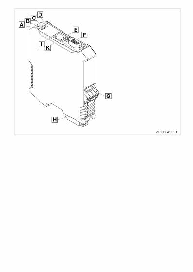
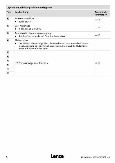
Legende zur Abbildung auf der Ausklappseite
Pos. Beschreibung AusführlicheInformation
� Ethernet−Anschluss� Buchse RJ45
��27
� CAN−Anschluss� 9−polige Sub−D−Buchse
��21
� Anschluss für Spannungsversorgung� 4−polige Steckerleiste mit Federkraftanschluss
��29
PE−Anschluss� Der PE−Anschluss erfolgt über die Hutschiene. Dazu muss das Kommu-
nikationsmodul auf die Hutschiene gesteckt sein und die Hutschienemuss mit PE verbunden sein!
LED−Statusanzeigen zur Diagnose ��31
�
�
�
�0Abb. 0Tab. 0
Inhalt i
EDKMF2180 DE/EN/FR/ES/IT 4.0 5�
Inhalt
1 Über diese Dokumentation 6. . . . . . . . . . . . . . . . . . . . . . . . . . . . . . . . . . . . . . . . . . . . Verwendete Konventionen 7. . . . . . . . . . . . . . . . . . . . . . . . . . . . . . . . . . . . . . . . . . . . Verwendete Hinweise 8. . . . . . . . . . . . . . . . . . . . . . . . . . . . . . . . . . . . . . . . . . . . . . . .
2 Sicherheitshinweise 10. . . . . . . . . . . . . . . . . . . . . . . . . . . . . . . . . . . . . . . . . . . . . . . . . .
3 Produktbeschreibung 11. . . . . . . . . . . . . . . . . . . . . . . . . . . . . . . . . . . . . . . . . . . . . . . . Funktion 11. . . . . . . . . . . . . . . . . . . . . . . . . . . . . . . . . . . . . . . . . . . . . . . . . . . . . . . . . . . Bestimmungsgemäße Verwendung 11. . . . . . . . . . . . . . . . . . . . . . . . . . . . . . . . . . . . Lieferumfang 11. . . . . . . . . . . . . . . . . . . . . . . . . . . . . . . . . . . . . . . . . . . . . . . . . . . . . . . Identifikation 12. . . . . . . . . . . . . . . . . . . . . . . . . . . . . . . . . . . . . . . . . . . . . . . . . . . . . . .
4 Technische Daten 13. . . . . . . . . . . . . . . . . . . . . . . . . . . . . . . . . . . . . . . . . . . . . . . . . . . . Allgemeine Daten und Einsatzbedingungen 13. . . . . . . . . . . . . . . . . . . . . . . . . . . . Schutzisolierung 14. . . . . . . . . . . . . . . . . . . . . . . . . . . . . . . . . . . . . . . . . . . . . . . . . . . . . Abmessungen 15. . . . . . . . . . . . . . . . . . . . . . . . . . . . . . . . . . . . . . . . . . . . . . . . . . . . . . .
5 Mechanische Installation 16. . . . . . . . . . . . . . . . . . . . . . . . . . . . . . . . . . . . . . . . . . . . .
6 Elektrische Installation 18. . . . . . . . . . . . . . . . . . . . . . . . . . . . . . . . . . . . . . . . . . . . . . . EMV−gerechte Verdrahtung 19. . . . . . . . . . . . . . . . . . . . . . . . . . . . . . . . . . . . . . . . . . . Systembus (CAN) anschließen 21. . . . . . . . . . . . . . . . . . . . . . . . . . . . . . . . . . . . . . . . . Ethernet−Anschluss 27. . . . . . . . . . . . . . . . . . . . . . . . . . . . . . . . . . . . . . . . . . . . . . . . . . Spannungsversorgung 29. . . . . . . . . . . . . . . . . . . . . . . . . . . . . . . . . . . . . . . . . . . . . . .
7 Inbetriebnahme 30. . . . . . . . . . . . . . . . . . . . . . . . . . . . . . . . . . . . . . . . . . . . . . . . . . . . . Vor dem ersten Einschalten 30. . . . . . . . . . . . . . . . . . . . . . . . . . . . . . . . . . . . . . . . . . .
8 Diagnose 31. . . . . . . . . . . . . . . . . . . . . . . . . . . . . . . . . . . . . . . . . . . . . . . . . . . . . . . . . . . LED−Statusanzeigen 31. . . . . . . . . . . . . . . . . . . . . . . . . . . . . . . . . . . . . . . . . . . . . . . . .
1 Über diese Dokumentation
EDKMF2180 DE/EN/FR/ES/IT 4.06 �
H1_Ueber_Doku−TIP_download_DE
1 Über diese Dokumentation
Inhalt
Diese Dokumentation enthält ...ƒ Sicherheitshinweise, die Sie unbedingt beachten müssen;ƒ Informationen zur bestimmungsgemäßen Verwendung und Technische Daten des
Kommunikationsmoduls;ƒ Informationen zur mechanischen und elektrischen Installation des
Kommunikationsmoduls;ƒ Informationen zur Diagnose.
Informationen zur Gültigkeit
Die Informationen in dieser Dokumentation sind gültig für folgende Geräte:
Kommunikationsmodul Typenbezeichnung ab Hardwarestand ab Softwarestand
EthernetCAN EMF2180IB 1x 1x
Zielgruppe
Diese Dokumentation wendet sich an Personen, die das beschriebene Produkt nach Projekt-vorgabe installieren und in Betrieb nehmen.
� Tipp!Informationen und Hilfsmittel rund um die Lenze−Produkte finden Sie imDownload−Bereich unter
www.lenze.com
Über diese DokumentationVerwendete Konventionen
1
EDKMF2180 DE/EN/FR/ES/IT 4.0 7�
H2_Verw_Konventionen−Verw_Konv_MA_KommModule
Verwendete Konventionen
Diese Dokumentation verwendet folgende Konventionen zur Unterscheidung verschiede-ner Arten von Information:
Informationsart Auszeichnung Beispiele/Hinweise
Zahlenschreibweise
Dezimaltrennzeichen Punkt Es wird generell der Dezimalpunktverwendet.Beispiel: 1234.56
Symbole
Seitenverweis � Verweis auf eine andere Seite mit zu-sätzlichen InformationenBeispiel: � 16 = siehe Seite 16
1 Über diese DokumentationVerwendete Hinweise
EDKMF2180 DE/EN/FR/ES/IT 4.08 �
H2_Def_Hinweise−SIC_pikt_DE
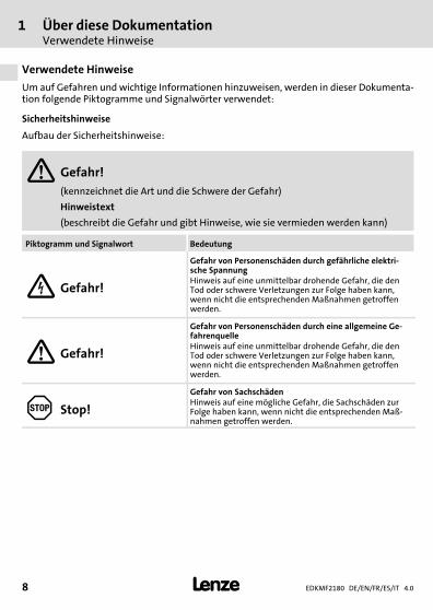
Verwendete Hinweise
Um auf Gefahren und wichtige Informationen hinzuweisen, werden in dieser Dokumenta-tion folgende Piktogramme und Signalwörter verwendet:
Sicherheitshinweise
Aufbau der Sicherheitshinweise:
� Gefahr!(kennzeichnet die Art und die Schwere der Gefahr)
Hinweistext
(beschreibt die Gefahr und gibt Hinweise, wie sie vermieden werden kann)
Piktogramm und Signalwort Bedeutung
� Gefahr!
Gefahr von Personenschäden durch gefährliche elektri-sche SpannungHinweis auf eine unmittelbar drohende Gefahr, die denTod oder schwere Verletzungen zur Folge haben kann,wenn nicht die entsprechenden Maßnahmen getroffenwerden.
� Gefahr!
Gefahr von Personenschäden durch eine allgemeine Ge-fahrenquelleHinweis auf eine unmittelbar drohende Gefahr, die denTod oder schwere Verletzungen zur Folge haben kann,wenn nicht die entsprechenden Maßnahmen getroffenwerden.
� Stop!
Gefahr von SachschädenHinweis auf eine mögliche Gefahr, die Sachschäden zurFolge haben kann, wenn nicht die entsprechenden Maß-nahmen getroffen werden.
Über diese DokumentationVerwendete Hinweise
1
EDKMF2180 DE/EN/FR/ES/IT 4.0 9�
H2_Def_Hinweise−SIC_pikt_DE
Anwendungshinweise
Piktogramm und Signalwort Bedeutung
� Hinweis! Wichtiger Hinweis für die störungsfreie Funktion
� Tipp! Nützlicher Tipp für die einfache Handhabung
� Verweis auf andere Dokumentation
2 Sicherheitshinweise
EDKMF2180 DE/EN/FR/ES/IT 4.010 �
H1sic_DE−stop_statEntlad_KommModule
2 Sicherheitshinweise
� Gefahr!Unsachgemäßer Umgang mit dem Kommunikationsmodul und demGrundgerät kann schwere Personenschäden und Sachschäden verursachen.
Beachten Sie die in der Dokumentation zum Grundgerät enthaltenenSicherheitshinweise und Restgefahren.
� Stop!Elektrostatische Entladung
Durch elektrostatische Entladung können elektronische Bauteile innerhalb desKommunikationsmoduls beschädigt oder zerstört werden.
Mögliche Folgen:ƒ Das Kommunikationsmodul ist defekt.ƒ Die Feldbus−Kommunikation ist nicht möglich oder fehlerhaft.
Schutzmaßnahmenƒ Befreien Sie sich vor dem Berühren des Moduls von elektrostatischen
Aufladungen.
ProduktbeschreibungFunktion
3
EDKMF2180 DE/EN/FR/ES/IT 4.0 11�
−H1−typbez
3 Produktbeschreibung
Funktion
Das Kommunikationsmodul dient mittels Fernwartung zur Parametrierung oder Program-mierung, Inbetriebnahme und Diagnose der einsetzbaren Lenze−Geräte.
Bestimmungsgemäße Verwendung
Das Kommunikationsmodul ist mit folgenden Lenze−Geräten einsetzbar:ƒ Servo Drives 9400ƒ Inverter Drives 8400ƒ Servo−Umrichter 9300ƒ 9300 vectorƒ 9300 Servo PLCƒ Servosystem ECSƒ Motorumrichter 8200 motecƒ Frequenzumrichter 8200 vectorƒ Frequenzumrichter 82XXƒ Drive PLCƒ Klemmenerweiterung 9374ƒ Bedien−/Anzeigeeinheit (EPM−HXXX)ƒ I/O−System IP20 (EPM−TXXX)
Lieferumfang
ƒ Kommunikationsmodul EMF2180IB (EthernetCAN)ƒ Montageanleitung
� Kommunikationshandbuch EMF2180IB (EthernetCAN)
Hier finden Sie weiterführende Informationen.
Die PDF−Datei finden Sie im Download−Bereich unter www.lenze.com.
3 ProduktbeschreibungIdentifikation
EDKMF2180 DE/EN/FR/ES/IT 4.012 �
−H1−typbez
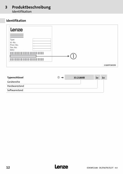
Identifikation
2180FEW099
Typenschlüssel � � 33.2180IB 1x 1x
Gerätereihe
Hardwarestand
Softwarestand
Technische DatenAllgemeine Daten und Einsatzbedingungen
4
EDKMF2180 DE/EN/FR/ES/IT 4.0 13�
H1_Daten−TabAbmess
4 Technische Daten
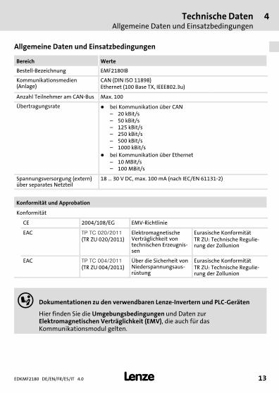
Allgemeine Daten und Einsatzbedingungen
Bereich Werte
Bestell−Bezeichnung EMF2180IB
Kommunikationsmedien(Anlage)
CAN (DIN ISO 11898)Ethernet (100 Base TX, IEEE802.3u)
Anzahl Teilnehmer am CAN−Bus Max. 100
Übertragungsrate � bei Kommunikation über CAN– 20 kBit/s– 50 kBit/s– 125 kBit/s– 250 kBit/s– 500 kBit/s– 1000 kBit/s
� bei Kommunikation über Ethernet– 10 MBit/s– 100 MBit/s
Spannungsversorgung (extern)über separates Netzteil
18 � 30 V DC, max. 100 mA (nach IEC/EN 61131−2)
Konformität und Approbation
Konformität
CE 2004/108/EG EMV−Richtlinie
EAC ������������
(TR ZU 020/2011)ElektromagnetischeVerträglichkeit vontechnischen Erzeugnis-sen
Eurasische KonformitätTR ZU: Technische Regulie-rung der Zollunion
EAC �����������
(TR ZU 004/2011)Über die Sicherheit vonNiederspannungsaus-rüstung
Eurasische KonformitätTR ZU: Technische Regulie-rung der Zollunion
� Dokumentationen zu den verwendbaren Lenze−Invertern und PLC−Geräten
Hier finden Sie die Umgebungsbedingungen und Daten zurElektromagnetischen Verträglichkeit (EMV), die auch für dasKommunikationsmodul gelten.
4 Technische DatenSchutzisolierung
EDKMF2180 DE/EN/FR/ES/IT 4.014 �
H1_Daten−TabAbmess
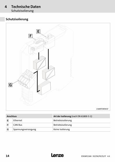
Schutzisolierung
2180FEW001F
Anschluss Art der Isolierung (nach EN 61800−5−1)
� Ethernet Betriebsisolierung
� CAN−Bus Betriebsisolierung
� Spannungsversorgung Keine Isolierung
Technische DatenAbmessungen
4
EDKMF2180 DE/EN/FR/ES/IT 4.0 15�
H1_Daten−TabAbmess
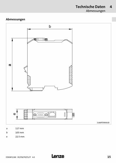
Abmessungen
2180FEW001B
a 117 mm
b 103 mm
e 22.5 mm
5 Mechanische Installation
EDKMF2180 DE/EN/FR/ES/IT 4.016 �
H1_MechINS−218x entriegeln
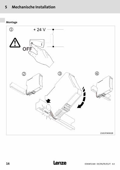
5 Mechanische Installation
Montage
2181FEW002B
Mechanische Installation 5
EDKMF2180 DE/EN/FR/ES/IT 4.0 17�
H1_MechINS−218x entriegeln
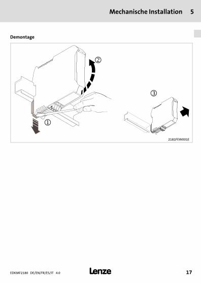
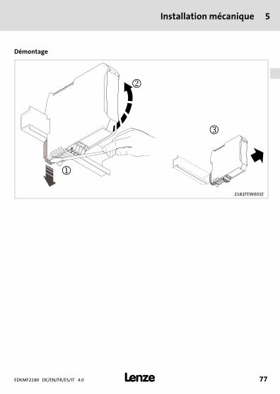
Demontage
2181FEW001E
6 Elektrische Installation
EDKMF2180 DE/EN/FR/ES/IT 4.018 �
H1_E_INST−SteckerFederkraftAnschluss FKCT
6 Elektrische Installation
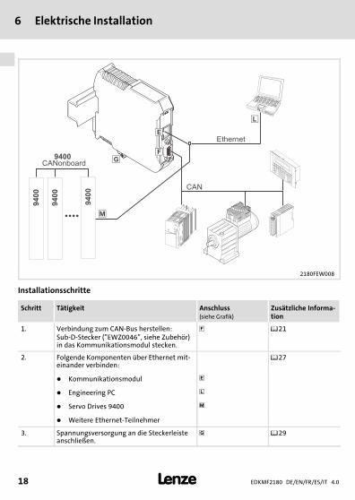
2180FEW008
Installationsschritte
Schritt Tätigkeit Anschluss(siehe Grafik)
Zusätzliche Informa-tion
1. Verbindung zum CAN−Bus herstellen:Sub−D−Stecker ("EWZ0046", siehe Zubehör)in das Kommunikationsmodul stecken.
� ��21
2. Folgende Komponenten über Ethernet mit-einander verbinden:
��27
� Kommunikationsmodul �
� Engineering PC �
� Servo Drives 9400 �
� Weitere Ethernet−Teilnehmer
3. Spannungsversorgung an die Steckerleisteanschließen.
� ��29
Elektrische InstallationEMV−gerechte Verdrahtung
6
EDKMF2180 DE/EN/FR/ES/IT 4.0 19�
H1_E_INST−SteckerFederkraftAnschluss FKCT
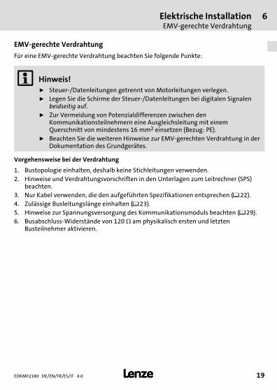
EMV−gerechte Verdrahtung
Für eine EMV−gerechte Verdrahtung beachten Sie folgende Punkte:
� Hinweis!ƒ Steuer−/Datenleitungen getrennt von Motorleitungen verlegen.ƒ Legen Sie die Schirme der Steuer−/Datenleitungen bei digitalen Signalen
beidseitig auf.ƒ Zur Vermeidung von Potenzialdifferenzen zwischen den
Kommunikationsteilnehmern eine Ausgleichsleitung mit einemQuerschnitt von mindestens 16�mm2 einsetzen (Bezug:�PE).
ƒ Beachten Sie die weiteren Hinweise zur EMV−gerechten Verdrahtung in derDokumentation des Grundgerätes.
Vorgehensweise bei der Verdrahtung
1. Bustopologie einhalten, deshalb keine Stichleitungen verwenden.2. Hinweise und Verdrahtungsvorschriften in den Unterlagen zum Leitrechner (SPS)
beachten.3. Nur Kabel verwenden, die den aufgeführten Spezifikationen entsprechen (��22).4. Zulässige Busleitungslänge einhalten (��23).
5. Hinweise zur Spannungsversorgung des Kommunikationsmoduls beachten (��29).6. Busabschluss−Widerstände von 120 � am physikalisch ersten und letzten
Busteilnehmer aktivieren.
6 Elektrische InstallationEMV−gerechte Verdrahtung
EDKMF2180 DE/EN/FR/ES/IT 4.020 �
H1_E_INST−SteckerFederkraftAnschluss FKCT
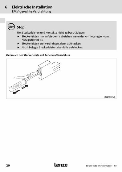
� Stop!Um Steckerleisten und Kontakte nicht zu beschädigen:ƒ Steckerleisten nur aufstecken / abziehen wenn der Antriebsregler vom
Netz getrennt ist.ƒ Steckerleisten erst verdrahten, dann aufstecken.ƒ Nicht belegte Steckerleisten ebenfalls aufstecken.
Gebrauch der Steckerleiste mit Federkraftanschluss
E82ZAFX013
Elektrische InstallationSystembus (CAN) anschließen
6
EDKMF2180 DE/EN/FR/ES/IT 4.0 21�
H1_E_INST−SteckerFederkraftAnschluss FKCT
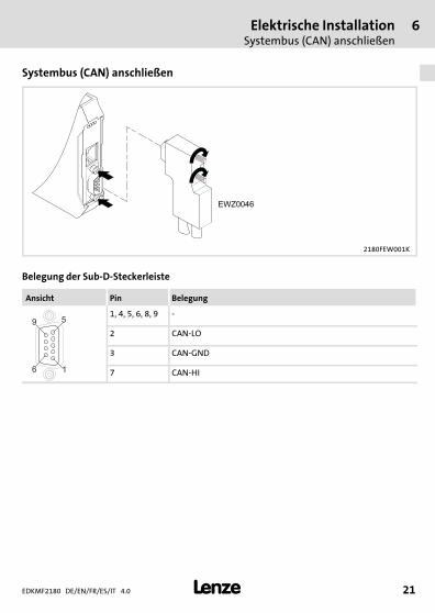
Systembus (CAN) anschließen
2180FEW001K
Belegung der Sub−D−Steckerleiste
Ansicht Pin Belegung
16
59
1, 4, 5, 6, 8, 9 −
2 CAN−LO
3 CAN−GND
7 CAN−HI
6 Elektrische InstallationSystembus (CAN) anschließen
EDKMF2180 DE/EN/FR/ES/IT 4.022 �
H1_E_INST−SteckerFederkraftAnschluss FKCT
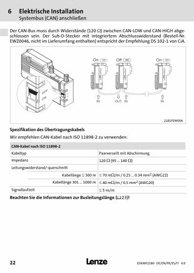
Der CAN−Bus muss durch Widerstände (120��) zwischen CAN−LOW und CAN−HIGH abge-schlossen sein. Der Sub−D−Stecker mit integriertem Abschlusswiderstand (Bestell−Nr.EWZ0046, nicht im Lieferumfang enthalten) entspricht der Empfehlung DS 102−1 von CiA.
L
EW
Z0046
OFF
ON
OFF
ON
ON
OFF
�
� � �
OUTIN IN IN
On Off On120 120 120
LE
WZ
00
46
LE
WZ
00
46
LE
WZ
00
46
2181FEW004
Spezifikation des Übertragungskabels
Wir empfehlen CAN−Kabel nach ISO 11898−2 zu verwenden:
CAN−Kabel nach ISO 11898−2
Kabeltyp Paarverseilt mit Abschirmung
Impedanz 120 � (95 ... 140 �)
Leitungswiderstand/−querschnitt
Kabellänge � 300 m � 70 m�/m / 0.25 � 0.34 mm2 (AWG22)
Kabellänge 301 � 1000 m � 40 m�/m / 0.5 mm2 (AWG20)
Signallaufzeit � 5 ns/m
Beachten Sie die Informationen zur Busleitungslänge (��23)!

Elektrische InstallationSystembus (CAN) anschließen
6
EDKMF2180 DE/EN/FR/ES/IT 4.0 23�
H1_E_INST−SteckerFederkraftAnschluss FKCT
Busleitungslänge
� Hinweis!ƒ Halten Sie die zulässigen Leitungslängen unbedingt ein.ƒ Wenn bei gleicher Übertragungsrate die zugehörigen
Gesamtleitungslängen der CAN−Teilnehmer unterschiedlich sind, muss zurBestimmung der max. Leitungslänge der kleinere Wert verwendet werden.
ƒ Beachten Sie die Reduzierung der Gesamtleitungslänge aufgrund derSignalverzögerung des Repeaters.
Gesamtleitungslänge
Durch die Übertragungsrate ist die Gesamtleitungslänge festgelegt.
Übertragungsrate [kBit/s] Max. Buslänge [m]
10 7450
20 3950
50 1550
125 630
250 290
500 120
1000 25
Tab. 1 Gesamtleitungslänge
6 Elektrische InstallationSystembus (CAN) anschließen
EDKMF2180 DE/EN/FR/ES/IT 4.024 �
H1_E_INST−SteckerFederkraftAnschluss FKCT
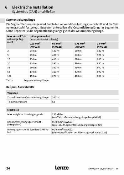
Segmentleitungslänge
Die Segmentleitungslänge wird durch den verwendeten Leitungsquerschnitt und die Teil-nehmeranzahl festgelegt. Repeater unterteilen die Gesamtleitungslänge in Segmente.Ohne Repeater ist die Segmentleitungslänge gleich der Gesamtleitungslänge.
Max. Anzahl Teil-nehmer je Seg-ment
Leitungsquerschnitt(Interpolation ist zulässig)
0.25 mm2
(AWG24)0.5 mm2
(AWG21)0.75 mm2
(AWG19)1.0 mm2
(AWG18)
2 240 m 430 m 650 m 940 m
5 230 m 420 m 640 m 920 m
10 230 m 410 m 620 m 900 m
20 210 m 390 m 580 m 850 m
32 200 m 360 m 550 m 800 m
63 170 m 310 m 470 m 690 m
100 150 m 270 m 410 m 600 m
Tab. 2 Segmentleitungslänge
Beispiel: Auswahlhilfe
Vorgaben
Zu realisierende Gesamtleitungslänge 200 m
Teilnehmeranzahl 63
Ergebnisse
Max. mögliche Übertragungsrate 250 kBit/s(aus Tab. 1 Gesamtleitungslänge hergeleitet)
Benötigter Leitungsquerschnitt(interpoliert)
0.30 mm2 (AWG23)(aus Tab. 2 Segmentleitungslänge hergeleitet)
Leitungsquerschnitt Standard CAN−Ka-bel
0.34 mm2 (AWG22)(siehe Spezifikation des Übertragungskabels ��22)
Elektrische InstallationSystembus (CAN) anschließen
6
EDKMF2180 DE/EN/FR/ES/IT 4.0 25�
H1_E_INST−SteckerFederkraftAnschluss FKCT
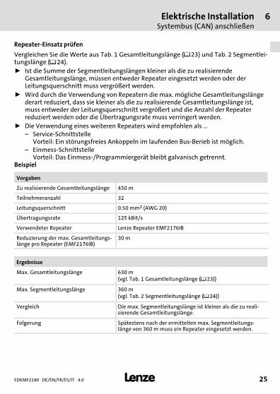
Repeater−Einsatz prüfen
Vergleichen Sie die Werte aus Tab. 1 Gesamtleitungslänge (��23) und Tab. 2 Segmentlei-tungslänge (��24).ƒ Ist die Summe der Segmentleitungslängen kleiner als die zu realisierende
Gesamtleitungslänge, müssen entweder Repeater eingesetzt werden oder derLeitungsquerschnitt muss vergrößert werden.
ƒ Wird durch die Verwendung von Repeatern die max. mögliche Gesamtleitungslängederart reduziert, dass sie kleiner als die zu realisierende Gesamtleitungslänge ist,muss entweder der Leitungsquerschnitt vergrößert und die Anzahl der Repeaterreduziert werden oder die Übertragungsrate muss verringert werden.
ƒ Die Verwendung eines weiteren Repeaters wird empfohlen als ...– Service−Schnittstelle
Vorteil: Ein störungsfreies Ankoppeln im laufenden Bus−Berieb ist möglich.– Einmess−Schnittstelle
Vorteil: Das Einmess−/Programmiergerät bleibt galvanisch getrennt.Beispiel
Vorgaben
Zu realisierende Gesamtleitungslänge 450 m
Teilnehmeranzahl 32
Leitungsquerschnitt 0.50 mm2 (AWG 20)
Übertragungsrate 125 kBit/s
Verwendeter Repeater Lenze Repeater EMF2176IB
Reduzierung der max. Gesamtleitungs-länge pro Repeater (EMF2176IB)
30 m
Ergebnisse
Max. Gesamtleitungslänge 630 m(vgl. Tab. 1 Gesamtleitungslänge (��23))
Max. Segmentleitungslänge 360 m(vgl. Tab. 2 Segmentleitungslänge (��24))
Vergleich Die max. Segmentleitungslänge ist kleiner als die zu reali-sierende Gesamtleitungslänge.
Folgerung Spätestens nach der ermittelten max. Segmentleitungs-länge von 360 m muss ein Repeater eingesetzt werden.
6 Elektrische InstallationSystembus (CAN) anschließen
EDKMF2180 DE/EN/FR/ES/IT 4.026 �
H1_E_INST−SteckerFederkraftAnschluss FKCT
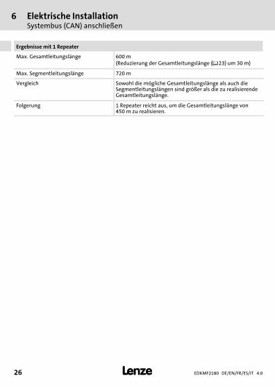
Ergebnisse mit 1 Repeater
Max. Gesamtleitungslänge 600 m(Reduzierung der Gesamtleitungslänge (��23) um 30 m)
Max. Segmentleitungslänge 720 m
Vergleich Sowohl die mögliche Gesamtleitungslänge als auch dieSegmentleitungslängen sind größer als die zu realisierendeGesamtleitungslänge.
Folgerung 1 Repeater reicht aus, um die Gesamtleitungslänge von450 m zu realisieren.
Elektrische InstallationEthernet−Anschluss
6
EDKMF2180 DE/EN/FR/ES/IT 4.0 27�
H1_E_INST−SteckerFederkraftAnschluss FKCT
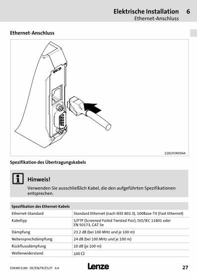
Ethernet−Anschluss
2181FEW004A
Spezifikation des Übertragungskabels
� Hinweis!Verwenden Sie ausschließlich Kabel, die den aufgeführten Spezifikationenentsprechen.
Spezifikation des Ethernet−Kabels
Ethernet−Standard Standard Ethernet (nach IEEE 802.3), 100Base−TX (Fast Ethernet)
Kabeltyp S/FTP (Screened Foiled Twisted Pair), ISO/IEC 11801 oderEN 50173, CAT 5e
Dämpfung 23.2 dB (bei 100 MHz und je 100 m)
Nebensprechdämpfung 24 dB (bei 100 MHz und je 100 m)
Rückflussdämpfung 10 dB (je 100 m)
Wellenwiderstand 100 �

6 Elektrische InstallationEthernet−Anschluss
EDKMF2180 DE/EN/FR/ES/IT 4.028 �
H1_E_INST−SteckerFederkraftAnschluss FKCT
Pin−Belegung
100BaseTX − CrossOver Cable 100BaseTX − Standard Patch Cable
1Tx+ Tx+1
2Tx- Tx-2
3Rx+ Rx+3
4 4
5 5
6Rx- Rx-6
7 7
8 8
1Tx+ Tx+1
2Tx- Tx-2
3Rx+ Rx+3
4 4
5 5
6Rx- Rx-6
7 7
8 8
E94YCEI002
Verwendung der Kabel
ƒ Das "100BaseTX − CrossOver Cable" wird bei direkter Kopplung des Engineering PCmit dem Kommunikationsmodul verwendet.
ƒ Das "100BaseTX − Standard Patch Cable" wird bei Verwendung von Hubs undSwitches eingesetzt.
Elektrische InstallationSpannungsversorgung
6
EDKMF2180 DE/EN/FR/ES/IT 4.0 29�
H1_E_INST−SteckerFederkraftAnschluss FKCT
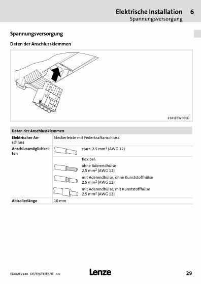
Spannungsversorgung
Daten der Anschlussklemmen
2181FEW001G
Daten der Anschlussklemmen
Elektrischer An-schluss
Steckerleiste mit Federkraftanschluss
Anschlussmöglichkei-ten
starr: 2.5 mm2 (AWG 12)
flexibel:
ohne Aderendhülse2.5 mm2 (AWG 12)
mit Aderendhülse, ohne Kunststoffhülse2.5 mm2 (AWG 12)
mit Aderendhülse, mit Kunststoffhülse2.5 mm2 (AWG 12)
Abisolierlänge 10 mm
7 InbetriebnahmeVor dem ersten Einschalten
EDKMF2180 DE/EN/FR/ES/IT 4.030 �
H1inbet−LESE_INB_KHB_Fernwartung
7 Inbetriebnahme
Vor dem ersten Einschalten
� Stop!Überprüfen Sie vor dem Einschalten der Netzspannung die gesamteVerdrahtung auf Vollständigkeit, Kurzschluss und Erdschluss.
� Kommunikationshandbuch EMF2180IB (EthernetCAN)
Hier finden Sie ausführliche Informationen zur Inbetriebnahme.
DiagnoseLED−Statusanzeigen
8
EDKMF2180 DE/EN/FR/ES/IT 4.0 31�
H1_Diagnose−st_00tu0
8 Diagnose
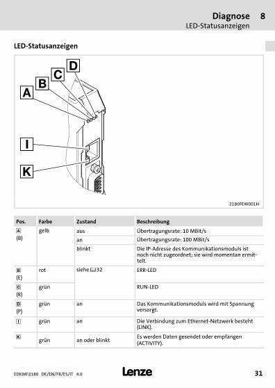
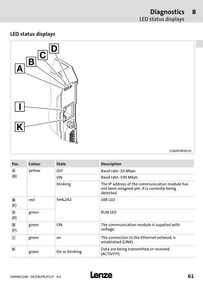
LED−Statusanzeigen
2180FEW001H
Pos. Farbe Zustand Beschreibung
(B)
gelb aus Übertragungsrate: 10 MBit/s
an Übertragungsrate: 100 MBit/s
blinkt Die IP−Adresse des Kommunikationsmoduls istnoch nicht zugeordnet; sie wird momentan ermit-telt.
�(E)
rot siehe ��32 ERR−LED
�(R)
grün RUN−LED
(P)
grün an Das Kommunikationsmoduls wird mit Spannungversorgt.
� grün an Die Verbindung zum Ethernet−Netzwerk besteht(LINK).
� grün an oder blinktEs werden Daten gesendet oder empfangen(ACTIVITY).
8 DiagnoseLED−Statusanzeigen
EDKMF2180 DE/EN/FR/ES/IT 4.032 �
H1_Diagnose−st_00tu0
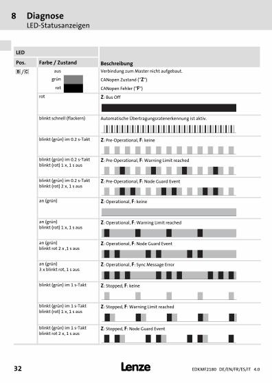
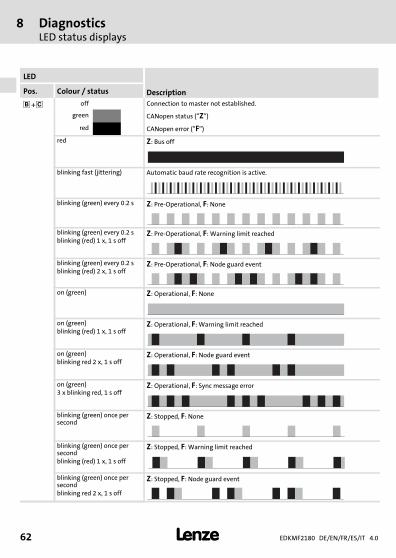
LED
BeschreibungPos. Farbe / Zustand
� / � aus Verbindung zum Master nicht aufgebaut.
grün CANopen Zustand ("Z")
rot CANopen Fehler ("F")
rot Z: Bus Off
blinkt schnell (flackern) Automatische Übertragungsratenerkennung ist aktiv.
blinkt (grün) im 0.2 s−Takt Z: Pre−Operational, F: keine
blinkt (grün) im 0.2 s−Taktblinkt (rot) 1 x, 1 s aus
Z: Pre−Operational, F: Warning Limit reached
blinkt (grün) im 0.2 s−Taktblinkt (rot) 2 x, 1 s aus
Z: Pre−Operational, F: Node Guard Event
an (grün) Z: Operational, F: keine
an (grün)blinkt (rot) 1 x, 1 s aus
Z: Operational, F: Warning Limit reached
an (grün)blinkt rot 2 x ,1 s aus
Z: Operational, F: Node Guard Event
an (grün)3 x blinkt rot, 1 s aus
Z: Operational, F: Sync Message Error
blinkt (grün) im 1 s−Takt Z: Stopped, F: keine
blinkt (grün) im 1 s−Taktblinkt (rot) 1 x, 1 s aus
Z: Stopped, F: Warning Limit reached
blinkt (grün) im 1 s−Taktblinkt rot 2 x, 1 s aus
Z: Stopped, F: Node Guard Event
DiagnoseLED−Statusanzeigen
8
EDKMF2180 DE/EN/FR/ES/IT 4.0 33�
H1_Diagnose−st_00tu0
EDKMF2180 DE/EN/FR/ES/IT 4.034 �
legende_kopfzeile−DUMMY_NUM_Reset
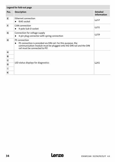
Legend for fold−out page
Pos. Description Detailedinformation
� Ethernet connection� RJ45 socket
��57
� CAN connection� 9−pole Sub−D socket
��51
� Connection for voltage supply� 4−pin plug connector with spring connection
��59
PE connection� PE connection is provided via DIN rail. For this purpose, the
communication module must be plugged onto the DIN rail and the DINrail must be connected to PE!
LED status displays for diagnostics ��61
�
�
�
�0Fig. 0Tab. 0
Contents i
EDKMF2180 DE/EN/FR/ES/IT 4.0 35�
Inhalt
1 About this documentation 36. . . . . . . . . . . . . . . . . . . . . . . . . . . . . . . . . . . . . . . . . . . . Conventions used 37. . . . . . . . . . . . . . . . . . . . . . . . . . . . . . . . . . . . . . . . . . . . . . . . . . . . Notes used 38. . . . . . . . . . . . . . . . . . . . . . . . . . . . . . . . . . . . . . . . . . . . . . . . . . . . . . . . .
2 Safety instructions 40. . . . . . . . . . . . . . . . . . . . . . . . . . . . . . . . . . . . . . . . . . . . . . . . . . .
3 Product description 41. . . . . . . . . . . . . . . . . . . . . . . . . . . . . . . . . . . . . . . . . . . . . . . . . . Function 41. . . . . . . . . . . . . . . . . . . . . . . . . . . . . . . . . . . . . . . . . . . . . . . . . . . . . . . . . . . Application as directed 41. . . . . . . . . . . . . . . . . . . . . . . . . . . . . . . . . . . . . . . . . . . . . . Scope of supply 41. . . . . . . . . . . . . . . . . . . . . . . . . . . . . . . . . . . . . . . . . . . . . . . . . . . . . . Identification 42. . . . . . . . . . . . . . . . . . . . . . . . . . . . . . . . . . . . . . . . . . . . . . . . . . . . . . .
4 Technical data 43. . . . . . . . . . . . . . . . . . . . . . . . . . . . . . . . . . . . . . . . . . . . . . . . . . . . . . . General data and operating conditions 43. . . . . . . . . . . . . . . . . . . . . . . . . . . . . . . . Protective insulation 44. . . . . . . . . . . . . . . . . . . . . . . . . . . . . . . . . . . . . . . . . . . . . . . . . Dimensions 45. . . . . . . . . . . . . . . . . . . . . . . . . . . . . . . . . . . . . . . . . . . . . . . . . . . . . . . . .
5 Mechanical installation 46. . . . . . . . . . . . . . . . . . . . . . . . . . . . . . . . . . . . . . . . . . . . . . .
6 Electrical installation 48. . . . . . . . . . . . . . . . . . . . . . . . . . . . . . . . . . . . . . . . . . . . . . . . . EMC−compliant wiring 49. . . . . . . . . . . . . . . . . . . . . . . . . . . . . . . . . . . . . . . . . . . . . . . . Connection of system bus (CAN) 51. . . . . . . . . . . . . . . . . . . . . . . . . . . . . . . . . . . . . . . Ethernet connection 57. . . . . . . . . . . . . . . . . . . . . . . . . . . . . . . . . . . . . . . . . . . . . . . . . Voltage supply 59. . . . . . . . . . . . . . . . . . . . . . . . . . . . . . . . . . . . . . . . . . . . . . . . . . . . .
7 Commissioning 60. . . . . . . . . . . . . . . . . . . . . . . . . . . . . . . . . . . . . . . . . . . . . . . . . . . . . Before switching on 60. . . . . . . . . . . . . . . . . . . . . . . . . . . . . . . . . . . . . . . . . . . . . . . . .
8 Diagnostics 61. . . . . . . . . . . . . . . . . . . . . . . . . . . . . . . . . . . . . . . . . . . . . . . . . . . . . . . . . LED status displays 61. . . . . . . . . . . . . . . . . . . . . . . . . . . . . . . . . . . . . . . . . . . . . . . . . .

1 About this documentation
EDKMF2180 DE/EN/FR/ES/IT 4.036 �
H1_Über_die_Doku−TIP_download_DE
1 About this documentation
Contents
This documentation contains ...ƒ safety instructions which must be observed by all means;ƒ information on the application as directed and technical data of the communication
module;ƒ information on the mechanical and electrical installation of the communication
module;ƒ Diagnostics information.
Validity information
The information given in this documentation is valid for the following devices:
Communication module Type designation From hardwareversion upwards
From softwareversion upwards
EthernetCAN EMF2180IB 1x 1x
Target group
This documentation is intended for persons who install and commission the describedproduct according to the project requirements.
� Tip!Information and tools concerning the Lenze products can be found in thedownload area under
www.lenze.com
About this documentationConventions used
1
EDKMF2180 DE/EN/FR/ES/IT 4.0 37�
H2_Verw_Konventionen−Verw_Konv_MA_KommModule
Conventions used
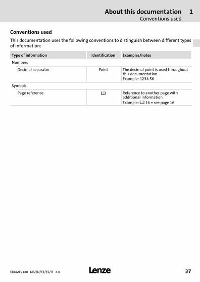
This documentation uses the following conventions to distinguish between different typesof information:
Type of information Identification Examples/notes
Numbers
Decimal separator Point The decimal point is used throughoutthis documentation.Example: 1234.56
Symbols
Page reference � Reference to another page withadditional informationExample: � 16 = see page 16
1 About this documentationNotes used
EDKMF2180 DE/EN/FR/ES/IT 4.038 �
H2_Def_Hinweise−SIC_pikt_EN
Notes used
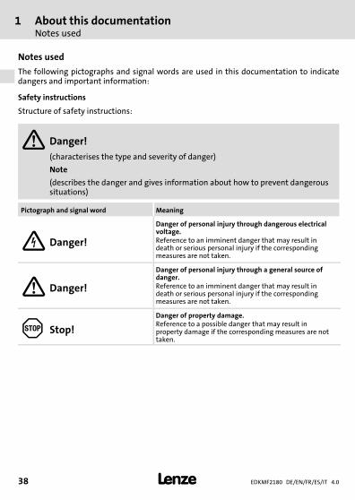
The following pictographs and signal words are used in this documentation to indicatedangers and important information:
Safety instructions
Structure of safety instructions:
� Danger!(characterises the type and severity of danger)
Note
(describes the danger and gives information about how to prevent dangeroussituations)
Pictograph and signal word Meaning
� Danger!
Danger of personal injury through dangerous electricalvoltage.Reference to an imminent danger that may result indeath or serious personal injury if the correspondingmeasures are not taken.
� Danger!
Danger of personal injury through a general source ofdanger.Reference to an imminent danger that may result indeath or serious personal injury if the correspondingmeasures are not taken.
� Stop!
Danger of property damage.Reference to a possible danger that may result inproperty damage if the corresponding measures are nottaken.
About this documentationNotes used
1
EDKMF2180 DE/EN/FR/ES/IT 4.0 39�
H2_Def_Hinweise−SIC_pikt_EN
Application notes
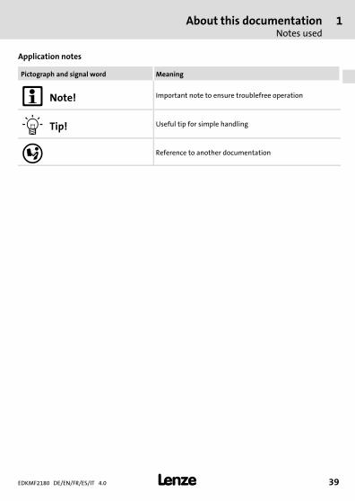
Pictograph and signal word Meaning
� Note! Important note to ensure troublefree operation
� Tip! Useful tip for simple handling
� Reference to another documentation
2 Safety instructions
EDKMF2180 DE/EN/FR/ES/IT 4.040 �
H1sic_EN−stop_statEntlad_KommModule
2 Safety instructions
� Danger!Inappropriate handling of the communication module and the standard devicecan cause serious personal injury and material damage.
Observe the safety instructions and residual hazards described in thedocumentation for the standard device.
� Stop!Electrostatic discharge
Electronic components of the communication module can be damaged ordestroyed through electrostatic discharge.
Possible consequences:ƒ The communication module is damaged.ƒ Fieldbus communication is not possible or faulty.
Protective measuresƒ Discharge electrostatic charges before touching the module.
Product descriptionFunction
3
EDKMF2180 DE/EN/FR/ES/IT 4.0 41�
−H1−typbez
3 Product description
Function
The communication module is used for setting parameters during remote maintenance orprogramming, commissioning and diagnosing the usable Lenze devices.
Application as directed
The communication module can be used with the following Lenze devices:ƒ Servo Drives 9400ƒ Inverter Drives 8400ƒ 9300 servo inverterƒ 9300 vectorƒ 9300 Servo PLCƒ ECS servo systemƒ 8200 motec motor inverterƒ 8200 vector frequency inverterƒ 82XX frequency inverterƒ Drive PLCƒ Terminal extension 9374ƒ Control / display unit (EPM−HXXX)ƒ I/O system IP20 (EPM−TXXX)
Scope of supply
ƒ EMF2180IB communication module (EthernetCAN)ƒ Mounting instructions
� EMF2180IB communication manual (EthernetCAN)
Further information is provided here.
The PDF file is provided in the download area at www.lenze.com.
3 Product descriptionIdentification
EDKMF2180 DE/EN/FR/ES/IT 4.042 �
−H1−typbez
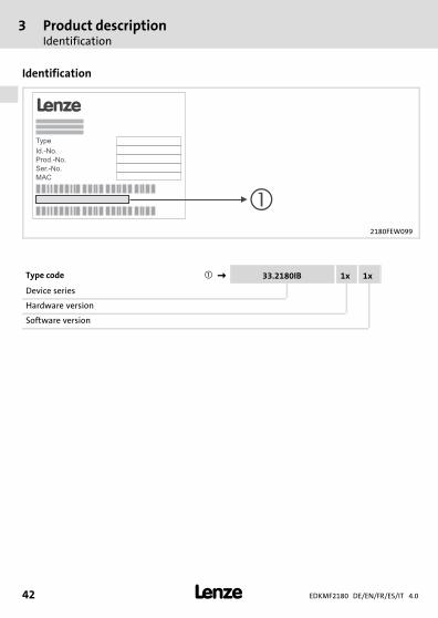
Identification
2180FEW099
Type code ���� 33.2180IB 1x 1x
Device series
Hardware version
Software version
Technical dataGeneral data and operating conditions
4
EDKMF2180 DE/EN/FR/ES/IT 4.0 43�
H1_Daten−TabAbmess
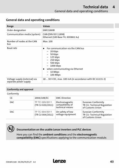
4 Technical data
General data and operating conditions
Range Values
Order designation EMF2180IB
Communication media (system) CAN (DIN ISO 11898)Ethernet (100 Base TX, IEEE802.3u)
Number of nodes at the CANbus
Max. 100
Baud rate � For communication via the CAN bus– 20 kbps– 50 kbps– 125 kbps– 250 kbps– 500 kbps– 1000 kbps
� when communicating via Ethernet– 10 Mbps– 100 Mbps
Voltage supply (external) viaseparate power supply
18 � 30 V DC, max. 100 mA (in accordance with IEC 61131−2)
Conformity and approval
Conformity
CE 2004/108/EC EMC Directive
EAC ������������
(TR CU 020/2011)Electromagneticcompatibility oftechnical means
Eurasian ConformityTR CU: Technical Regulationof Customs Union
EAC �����������
(TR CU 004/2011)On safety of lowvoltage equipment
Eurasian ConformityTR CU: Technical Regulationof Customs Union
� Documentation on the usable Lenze inverters and PLC devices
Here you can find the ambient conditions and the electromagneticcompatibility (EMC) specifications applying to the communication module.
4 Technical dataProtective insulation
EDKMF2180 DE/EN/FR/ES/IT 4.044 �
H1_Daten−TabAbmess
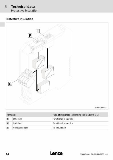
Protective insulation
2180FEW001F
Terminal Type of insulation (according to EN 61800−5−1)
� Ethernet Functional insulation
� CAN bus Functional insulation
� Voltage supply No insulation

Technical dataDimensions
4
EDKMF2180 DE/EN/FR/ES/IT 4.0 45�
H1_Daten−TabAbmess
Dimensions
2180FEW001B
a 117 mm
b 103 mm
e 22.5 mm
5 Mechanical installation
EDKMF2180 DE/EN/FR/ES/IT 4.046 �
H1_MechINS−218x entriegeln
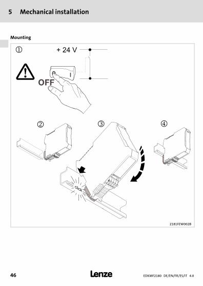
5 Mechanical installation
Mounting
2181FEW002B

Mechanical installation 5
EDKMF2180 DE/EN/FR/ES/IT 4.0 47�
H1_MechINS−218x entriegeln
Dismounting
2181FEW001E

6 Electrical installation
EDKMF2180 DE/EN/FR/ES/IT 4.048 �
H1_E_INST−SteckerFederkraftAnschluss FKCT
6 Electrical installation
2180FEW008
Installation steps
Step Activity Terminal(see graphic)
Additionalinformation
1. Establish a connection to the CAN bus:Insert SUB−D plug ("EWZ0046", seeAccessories) in the communication module.
� ��51
2. Connect the following components viaEthernet with each other:
��57
� Communication module �
� Engineering PC �
� Servo Drives 9400 �
� Other Ethernet nodes
3. Connect voltage supply to the plugconnector.
� ��59
Electrical installationEMC−compliant wiring
6
EDKMF2180 DE/EN/FR/ES/IT 4.0 49�
H1_E_INST−SteckerFederkraftAnschluss FKCT
EMC−compliant wiring
For wiring according to EMC requirements observe the following points:
� Note!ƒ Separate control cables/data lines from motor cables.ƒ Connect the shields of control cables/data lines at both ends in the case of
digital signals.ƒ Use an equalizing conductor with a cross−section of at least 16�mm2
(reference:�PE) to avoid potential differences between the bus nodes.ƒ Observe the other notes concerning EMC−compliant wiring given in the
documentation for the standard device.
Procedure for wiring
1. Comply with bus topology, thus do not use stubs.2. Observe notes and wiring instructions in the documents for the master computer
(PLC).3. Only use cables that comply with the given specifications (��52).4. Observe the permissible bus cable length (��53).
5. Observe notes for the voltage supply of the communication module (��59).6. Activate bus terminating resistors of 120 � at the physically first and last node.
6 Electrical installationEMC−compliant wiring
EDKMF2180 DE/EN/FR/ES/IT 4.050 �
H1_E_INST−SteckerFederkraftAnschluss FKCT
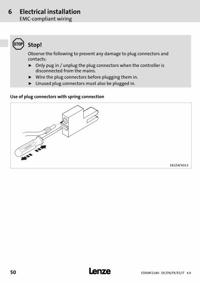
� Stop!Observe the following to prevent any damage to plug connectors andcontacts:ƒ Only pug in / unplug the plug connectors when the controller is
disconnected from the mains.ƒ Wire the plug connectors before plugging them in.ƒ Unused plug connectors must also be plugged in.
Use of plug connectors with spring connection
E82ZAFX013

Electrical installationConnection of system bus (CAN)
6
EDKMF2180 DE/EN/FR/ES/IT 4.0 51�
H1_E_INST−SteckerFederkraftAnschluss FKCT
Connection of system bus (CAN)
2180FEW001K
Assignment of the Sub−D plug connector
View Pin Assignment
16
59
1, 4, 5, 6, 8, 9 −
2 CAN−LO
3 CAN−GND
7 CAN−HI
6 Electrical installationConnection of system bus (CAN)
EDKMF2180 DE/EN/FR/ES/IT 4.052 �
H1_E_INST−SteckerFederkraftAnschluss FKCT
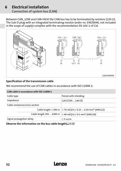
Between CAN_LOW and CAN−HIGH the CAN bus has to be terminated by resistors (120��).The Sub−D plug with an integrated terminating resistor (order no. EWZ0046, not includedin the scope of supply) complies with the recommendation DS 102−1 of CiA.
L
EW
Z0046
OFF
ON
OFF
ON
ON
OFF
�
� � �
OUTIN IN IN
On Off On120 120 120
LE
WZ
00
46
LE
WZ
00
46
LE
WZ
00
46
2181FEW004
Specification of the transmission cable
We recommend the use of CAN cables in accordance with ISO 11898−2:
CAN cable in accordance with ISO 11898−2
Cable type Paired with shielding
Impedance 120 � (95 ... 140 �)
Cable resistance/cross−section
Cable length � 300 m � 70 m�/m / 0.25 � 0.34 mm2 (AWG22)
Cable length 301 � 1000 m � 40 m�/m / 0.5 mm2 (AWG20)
Signal propagation delay � 5 ns/m
Observe the information on the bus cable length(��53)!
Electrical installationConnection of system bus (CAN)
6
EDKMF2180 DE/EN/FR/ES/IT 4.0 53�
H1_E_INST−SteckerFederkraftAnschluss FKCT
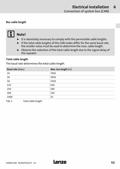
Bus cable length
� Note!ƒ It is absolutely necessary to comply with the permissible cable lengths.ƒ If the total cable lengths of the CAN nodes differ for the same baud rate,
the smaller value must be used to determine the max. cable length.ƒ Observe the reduction of the total cable length due to the signal delay of
the repeater.
Total cable length
The baud rate determines the total cable length.
Baud rate [kbps] Max. bus length [m]
10 7450
20 3950
50 1550
125 630
250 290
500 120
1000 25
Tab. 1 Total cable length
6 Electrical installationConnection of system bus (CAN)
EDKMF2180 DE/EN/FR/ES/IT 4.054 �
H1_E_INST−SteckerFederkraftAnschluss FKCT
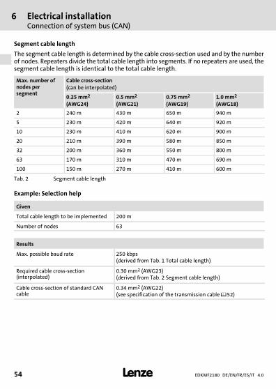
Segment cable length
The segment cable length is determined by the cable cross−section used and by the numberof nodes. Repeaters divide the total cable length into segments. If no repeaters are used, thesegment cable length is identical to the total cable length.
Max. number ofnodes persegment
Cable cross−section(can be interpolated)
0.25 mm2
(AWG24)0.5 mm2
(AWG21)0.75 mm2
(AWG19)1.0 mm2
(AWG18)
2 240 m 430 m 650 m 940 m
5 230 m 420 m 640 m 920 m
10 230 m 410 m 620 m 900 m
20 210 m 390 m 580 m 850 m
32 200 m 360 m 550 m 800 m
63 170 m 310 m 470 m 690 m
100 150 m 270 m 410 m 600 m
Tab. 2 Segment cable length
Example: Selection help
Given
Total cable length to be implemented 200 m
Number of nodes 63
Results
Max. possible baud rate 250 kbps(derived from Tab. 1 Total cable length)
Required cable cross−section(interpolated)
0.30 mm2 (AWG23)(derived from Tab. 2 Segment cable length)
Cable cross−section of standard CANcable
0.34 mm2 (AWG22)(see specification of the transmission cable ��52)
Electrical installationConnection of system bus (CAN)
6
EDKMF2180 DE/EN/FR/ES/IT 4.0 55�
H1_E_INST−SteckerFederkraftAnschluss FKCT
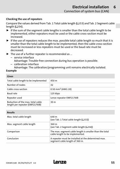
Checking the use of repeaters
Compare the values derived from Tab. 1 Total cable length (��53) and Tab. 2 Segment cablelength (��54).ƒ If the sum of the segment cable lengths is smaller than the total cable length to be
implemented, either repeaters must be used or the cable cross−section must beincreased.
ƒ If the use of repeaters reduces the max. possible total cable length so much that it issmaller than the total cable length to be implemented, then the cable cross−sectionmust be increased or less repeaters must be used or the baud rate must bedecreased.
ƒ The use of a further repeater is recommended as ...– service interface
Advantage: Trouble−free connection during bus operation is possible.– calibration interface
Advantage: The calibration/programming unit remains electrically isolated.Example
Given
Total cable length to be implemented 450 m
Number of nodes 32
Cable cross−section 0.50 mm2 (AWG 20)
Baud rate 125 kbps
Repeater used Lenze repeater EMF2176IB
Reduction of the max. total cablelength per repeater (EMF2176IB)
30 m
Results
Max. total cable length 630 m(see Tab. 1 Total cable length (��53))
Max. segment cable length 360 m(see Tab. 2 Segment cable length (��54))
Comparison The max. segment cable length is smaller than the totalcable length to be implemented.
Conclusion A repeater must be installed at the determined max.segment cable length of 360 m.

6 Electrical installationConnection of system bus (CAN)
EDKMF2180 DE/EN/FR/ES/IT 4.056 �
H1_E_INST−SteckerFederkraftAnschluss FKCT
Results with 1 repeater
Max. total cable length 600 m(Reduction of the total cable length (��53) by 30 m)
Max. segment cable length 720 m
Comparison Both the possible total cable length and the segment cablelengths are larger than the total cable length to beimplemented.
Conclusion 1 repeater is sufficient to implement the total cable lengthof 450 m.
Electrical installationEthernet connection
6
EDKMF2180 DE/EN/FR/ES/IT 4.0 57�
H1_E_INST−SteckerFederkraftAnschluss FKCT
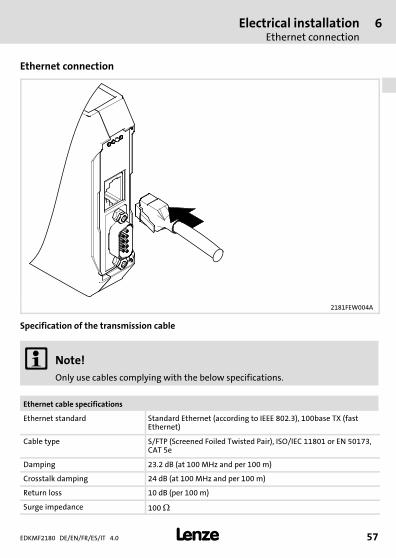
Ethernet connection
2181FEW004A
Specification of the transmission cable
� Note!Only use cables complying with the below specifications.
Ethernet cable specifications
Ethernet standard Standard Ethernet (according to IEEE 802.3), 100base TX (fastEthernet)
Cable type S/FTP (Screened Foiled Twisted Pair), ISO/IEC 11801 or EN 50173,CAT 5e
Damping 23.2 dB (at 100 MHz and per 100 m)
Crosstalk damping 24 dB (at 100 MHz and per 100 m)
Return loss 10 dB (per 100 m)
Surge impedance 100 �
6 Electrical installationEthernet connection
EDKMF2180 DE/EN/FR/ES/IT 4.058 �
H1_E_INST−SteckerFederkraftAnschluss FKCT
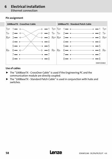
Pin assignment
100BaseTX − CrossOver Cable 100BaseTX − Standard Patch Cable
1Tx+ Tx+1
2Tx- Tx-2
3Rx+ Rx+3
4 4
5 5
6Rx- Rx-6
7 7
8 8
1Tx+ Tx+1
2Tx- Tx-2
3Rx+ Rx+3
4 4
5 5
6Rx- Rx-6
7 7
8 8
E94YCEI002
Use of cables
ƒ The "100BaseTX − CrossOver Cable" is used if the Engineering PC and thecommunication module are directly coupled.
ƒ The "100BaseTX − Standard Patch Cable" is used in conjunction with hubs andswitches.
Electrical installationVoltage supply
6
EDKMF2180 DE/EN/FR/ES/IT 4.0 59�
H1_E_INST−SteckerFederkraftAnschluss FKCT
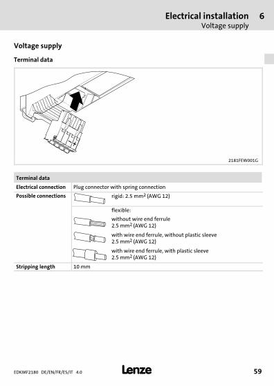
Voltage supply
Terminal data
2181FEW001G
Terminal data
Electrical connection Plug connector with spring connection
Possible connections rigid: 2.5 mm2 (AWG 12)
flexible:
without wire end ferrule2.5 mm2 (AWG 12)
with wire end ferrule, without plastic sleeve2.5 mm2 (AWG 12)
with wire end ferrule, with plastic sleeve2.5 mm2 (AWG 12)
Stripping length 10 mm
7 CommissioningBefore switching on
EDKMF2180 DE/EN/FR/ES/IT 4.060 �
H1inbet−LESE_INB_KHB_Fernwartung
7 Commissioning
Before switching on
� Stop!Prior to switching on the mains voltage, check the wiring for completeness,short−circuit and earth fault.
� EMF2180IB communication manual (EthernetCAN)
Detailed information on commissioning can be found here.
DiagnosticsLED status displays
8
EDKMF2180 DE/EN/FR/ES/IT 4.0 61�
H1_Diagnose−st_00tu0
8 Diagnostics
LED status displays
2180FEW001H
Pos. Colour State Description
(B)
yellow OFF Baud rate: 10 Mbps
ON Baud rate: 100 Mbps
blinking The IP address of the communication module hasnot been assigned yet; it is currently beingdetected.
�(E)
red See��62 ERR LED
�(R)
green RUN LED
(P)
green ON The communication module is supplied withvoltage.
� green on The connection to the Ethernet network isestablished (LINK).
� green On or blinkingData are being transmitted or received(ACTIVITY).
8 DiagnosticsLED status displays
EDKMF2180 DE/EN/FR/ES/IT 4.062 �
H1_Diagnose−st_00tu0
LED
DescriptionPos. Colour / status
��+ � off Connection to master not established.
green CANopen status ("Z")
red CANopen error ("F")
red Z: Bus off
blinking fast (jittering) Automatic baud rate recognition is active.
blinking (green) every 0.2 s Z: Pre−Operational, F: None
blinking (green) every 0.2 sblinking (red) 1 x, 1 s off
Z: Pre−Operational, F: Warning limit reached
blinking (green) every 0.2 sblinking (red) 2 x, 1 s off
Z: Pre−Operational, F: Node guard event
on (green) Z: Operational, F: None
on (green)blinking (red) 1 x, 1 s off
Z: Operational, F: Warning limit reached
on (green)blinking red 2 x, 1 s off
Z: Operational, F: Node guard event
on (green)3 x blinking red, 1 s off
Z: Operational, F: Sync message error
blinking (green) once persecond
Z: Stopped, F: None
blinking (green) once persecondblinking (red) 1 x, 1 s off
Z: Stopped, F: Warning limit reached
blinking (green) once persecondblinking red 2 x, 1 s off
Z: Stopped, F: Node guard event
DiagnosticsLED status displays
8
EDKMF2180 DE/EN/FR/ES/IT 4.0 63�
H1_Diagnose−st_00tu0

EDKMF2180 DE/EN/FR/ES/IT 4.064 �
legende_kopfzeile−DUMMY_NUM_Reset
Légende de l’illustration de la page dépliante
Pos. Description Informationsdétaillées
� Raccordement Ethernet� Prise RJ45
��87
� Raccordement CAN� Connecteur Sub−D femelle 9 broches
��81
� Raccordement Alimentation� Bornier à lame ressort 4 bornes
��89
Raccordement PE� Le raccordement PE est réalisé via le rail profilé. Le module de
communication doit être enfiché sur le rail profilé et ce dernier doit êtrerelié à la terre (PE).
Affichages d’état par LED à des fins de diagnostic ��91
�
�
�
�0Fig. 0Tab. 0
Sommaire i
EDKMF2180 DE/EN/FR/ES/IT 4.0 65�
Inhalt
1 Présentation du document 66. . . . . . . . . . . . . . . . . . . . . . . . . . . . . . . . . . . . . . . . . . . . Conventions utilisées 67. . . . . . . . . . . . . . . . . . . . . . . . . . . . . . . . . . . . . . . . . . . . . . . . . Consignes utilisées 68. . . . . . . . . . . . . . . . . . . . . . . . . . . . . . . . . . . . . . . . . . . . . . . . . . .
2 Consignes de sécurité 70. . . . . . . . . . . . . . . . . . . . . . . . . . . . . . . . . . . . . . . . . . . . . . . .
3 Description du produit 71. . . . . . . . . . . . . . . . . . . . . . . . . . . . . . . . . . . . . . . . . . . . . . . . Fonction 71. . . . . . . . . . . . . . . . . . . . . . . . . . . . . . . . . . . . . . . . . . . . . . . . . . . . . . . . . . . Utilisation conforme à la fonction 71. . . . . . . . . . . . . . . . . . . . . . . . . . . . . . . . . . . . . Équipement livré> 71. . . . . . . . . . . . . . . . . . . . . . . . . . . . . . . . . . . . . . . . . . . . . . . . . . . Identification 72. . . . . . . . . . . . . . . . . . . . . . . . . . . . . . . . . . . . . . . . . . . . . . . . . . . . . . .
4 Spécifications techniques 73. . . . . . . . . . . . . . . . . . . . . . . . . . . . . . . . . . . . . . . . . . . . . Caractéristiques générales et conditions d’utilisation 73. . . . . . . . . . . . . . . . . . . . Isolement de protection 74. . . . . . . . . . . . . . . . . . . . . . . . . . . . . . . . . . . . . . . . . . . . . . Encombrements 75. . . . . . . . . . . . . . . . . . . . . . . . . . . . . . . . . . . . . . . . . . . . . . . . . . . . .
5 Installation mécanique 76. . . . . . . . . . . . . . . . . . . . . . . . . . . . . . . . . . . . . . . . . . . . . . .
6 Installation électrique 78. . . . . . . . . . . . . . . . . . . . . . . . . . . . . . . . . . . . . . . . . . . . . . . . Câblage conforme CEM 79. . . . . . . . . . . . . . . . . . . . . . . . . . . . . . . . . . . . . . . . . . . . . . . Raccordement du Bus Système CAN 81. . . . . . . . . . . . . . . . . . . . . . . . . . . . . . . . . . . . Raccordement Ethernet 87. . . . . . . . . . . . . . . . . . . . . . . . . . . . . . . . . . . . . . . . . . . . . . . Alimentation 89. . . . . . . . . . . . . . . . . . . . . . . . . . . . . . . . . . . . . . . . . . . . . . . . . . . . . . .
7 Mise en service 90. . . . . . . . . . . . . . . . . . . . . . . . . . . . . . . . . . . . . . . . . . . . . . . . . . . . . . Avant la première mise sous tension 90. . . . . . . . . . . . . . . . . . . . . . . . . . . . . . . . . . . .
8 Diagnostic 91. . . . . . . . . . . . . . . . . . . . . . . . . . . . . . . . . . . . . . . . . . . . . . . . . . . . . . . . . . Affichages d’état par LED 91. . . . . . . . . . . . . . . . . . . . . . . . . . . . . . . . . . . . . . . . . . . . .
1 Présentation du document
EDKMF2180 DE/EN/FR/ES/IT 4.066 �
H1_Über_die_Doku−TIP_download_FR
1 Présentation du document
Contenu
Le présent document contient ...ƒ des consignes de sécurité à respecter impérativement ;ƒ des informations relatives à l’utilisation conforme à la fonction et aux spécifications
techniques du module de communication ;ƒ des informations sur l’installation mécanique et électrique du module de
communication ;ƒ des informations relatives au diagnostic.
Validité
Les informations contenues dans le présent document s’appliquent aux appareils suivants :
Module de communication Référence decommande
À partir de la versionmatérielle
À partir de la versionlogicielle
EthernetCAN EMF2180IB 1x 1x
Public visé
Ce document est destiné aux personnes chargées d’installer et de mettre en service leproduit décrit selon les exigences du projet.
� Conseil !Toutes les informations relatives aux produits Lenze peuvent être téléchargéessur notre site à l’adresse suivante :
www.Lenze.com
Présentation du documentConventions utilisées
1
EDKMF2180 DE/EN/FR/ES/IT 4.0 67�
H2_Verw_Konventionen−Verw_Konv_MA_KommModule
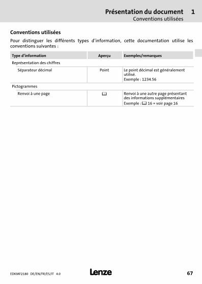
Conventions utilisées
Pour distinguer les différents types d’information, cette documentation utilise lesconventions suivantes :
Type d’information Aperçu Exemples/remarques
Représentation des chiffres
Séparateur décimal Point Le point décimal est généralementutilisé.Exemple : 1234.56
Pictogrammes
Renvoi à une page � Renvoi à une autre page présentantdes informations supplémentairesExemple : � 16 = voir page 16
1 Présentation du documentConsignes utilisées
EDKMF2180 DE/EN/FR/ES/IT 4.068 �
H2_Def_Hinweise−SIC_pikt_FR
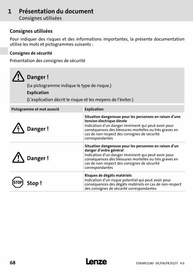
Consignes utilisées
Pour indiquer des risques et des informations importantes, la présente documentationutilise les mots et pictogrammes suivants :
Consignes de sécurité
Présentation des consignes de sécurité
� Danger !(Le pictogramme indique le type de risque.)
Explication
(L’explication décrit le risque et les moyens de l’éviter.)
Pictogramme et mot associé Explication
� Danger !
Situation dangereuse pour les personnes en raison d’unetension électrique élevéeIndication d’un danger imminent qui peut avoir pourconséquences des blessures mortelles ou très graves encas de non−respect des consignes de sécuritécorrespondantes
� Danger !
Situation dangereuse pour les personnes en raison d’undanger d’ordre généralIndication d’un danger imminent qui peut avoir pourconséquences des blessures mortelles ou très graves encas de non−respect des consignes de sécuritécorrespondantes
� Stop !
Risques de dégâts matérielsIndication d’un risque potentiel qui peut avoir pourconséquences des dégâts matériels en cas de non−respectdes consignes de sécurité correspondantes
Présentation du documentConsignes utilisées
1
EDKMF2180 DE/EN/FR/ES/IT 4.0 69�
H2_Def_Hinweise−SIC_pikt_FR
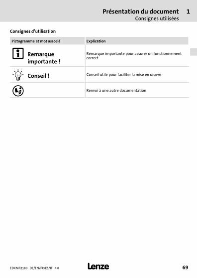
Consignes d’utilisation
Pictogramme et mot associé Explication
� Remarqueimportante !
Remarque importante pour assurer un fonctionnementcorrect
� Conseil ! Conseil utile pour faciliter la mise en �uvre
� Renvoi à une autre documentation

2 Consignes de sécurité
EDKMF2180 DE/EN/FR/ES/IT 4.070 �
H1sic_FR−stop_statEntlad_KommModule
2 Consignes de sécurité
� Danger !Toute utilisation non conforme à la fonction du module de communication etde l’appareil de base risque d’entraîner des blessures graves et des dommagesmatériels.
Tenir compte des consignes de sécurité et des dangers résiduels indiqués dansla documentation de l’appareil de base.
� Stop !Décharge électrostatique
Des composants électroniques à l’intérieur du module de communicationpeuvent être endommagés ou détruits par des décharges électrostatiques.
Risques encourus :ƒ Le module de communication est endommagé.ƒ La communication par bus de terrain est impossible ou erronée.
Mesures de protection :ƒ Se libérer des décharges électrostatiques avant toute manipulation du
module de communication.
Description du produitFonction
3
EDKMF2180 DE/EN/FR/ES/IT 4.0 71�
−H1−typbez
3 Description du produit
Fonction
Le module de communication est destiné au paramétrage ou à la programmation, à la miseen service et au diagnostic à distance des appareils Lenze compatibles.
Utilisation conforme à la fonction
Le module de communication est compatible avec les appareils Lenze ci−dessous :ƒ Servo Drives 9400ƒ Inverter Drives 8400ƒ Servovariateurs 9300ƒ 9300 vectorƒ 9300 Servo PLCƒ Système servo ECSƒ Motovariateurs 8200 motecƒ Convertisseurs de fréquence 8200 vectorƒ Convertisseurs de fréquence 82XXƒ Drive PLCƒ Bornes décentralisées 9374ƒ Interfaces homme−machine (EPM−HXXX)ƒ Système E/S IP20 (EPM−TXXX)
Équipement livré>
ƒ Module de communication EMF2180IB (EthernetCAN)ƒ Instructions de montage
� Manuel de communication EMF2180IB (EthernetCAN)
Consulter ce document pour des informations complémentaires.
Le fichier PDF peut être téléchargé sur Internet depuis la zone detéléchargement de notre site à l’adresse suivante : www.lenze.com.

3 Description du produitIdentification
EDKMF2180 DE/EN/FR/ES/IT 4.072 �
−H1−typbez
Identification
2180FEW099
Codification des types ���� 33.2180IB 1x 1x
Série d’appareils
Version matérielle
Version logicielle
Spécifications techniquesCaractéristiques générales et conditions d’utilisation
4
EDKMF2180 DE/EN/FR/ES/IT 4.0 73�
H1_Daten−TabAbmess
4 Spécifications techniques
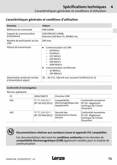
Caractéristiques générales et conditions d’utilisation
Domaine Valeurs
Référence de commande EMF2180IB
Support de communication(installation)
CAN (DIN ISO 11898)Ethernet (100 Base TX, IEEE802.3u)
Nombre de participants au busCAN
100 max.
Vitesse de transmission � Communication via CAN– 20 kbits/s– 50 kbits/s– 125 kbits/s– 250 kbits/s– 500 kbits/s– 1000 kbits/s
� Communication via Ethernet– 10 Mbits/s– 100 Mbits/s
Alimentation (externe) via blocd’alimentation séparé
18 � 30 V CC, 100 mA max. (suivant CEI/EN 61131−2)
Conformité et homologation
Normes appliquées
CE 2004/108/CE Directive CEM
EAC ������������
(RT UD 020/2011)Compatibilitéélectromagnétique deséquipements
Conformité eurasienneRT UD : Règlementtechnique de l’UnionDouanière
EAC �����������
(RT UD 004/2011)Sécurité deséquipements à bassetension
Conformité eurasienneRT UD : Règlementtechnique de l’UnionDouanière
� Documentations relatives aux variateurs Lenze et appareils PLC compatibles
Ces documentations décrivent les conditions ambiantes et les données decompatibilité électromagnétique (CEM) également valables pour le module decommunication.
4 Spécifications techniquesIsolement de protection
EDKMF2180 DE/EN/FR/ES/IT 4.074 �
H1_Daten−TabAbmess
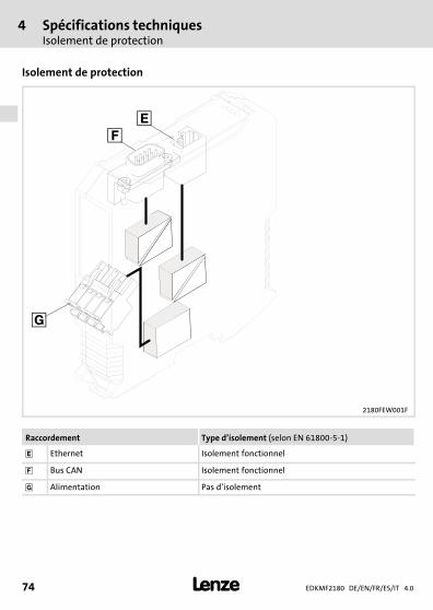
Isolement de protection
2180FEW001F
Raccordement Type d’isolement (selon EN 61800−5−1)
� Ethernet Isolement fonctionnel
� Bus CAN Isolement fonctionnel
� Alimentation Pas d’isolement
Spécifications techniquesEncombrements
4
EDKMF2180 DE/EN/FR/ES/IT 4.0 75�
H1_Daten−TabAbmess
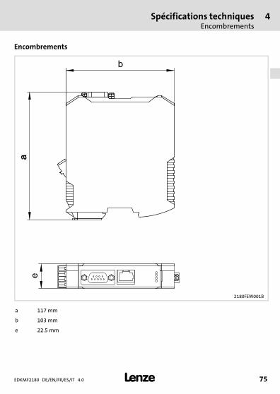
Encombrements
2180FEW001B
a 117 mm
b 103 mm
e 22.5 mm

5 Installation mécanique
EDKMF2180 DE/EN/FR/ES/IT 4.076 �
H1_MechINS−218x entriegeln
5 Installation mécanique
Montage
2181FEW002B
Installation mécanique 5
EDKMF2180 DE/EN/FR/ES/IT 4.0 77�
H1_MechINS−218x entriegeln
Démontage
2181FEW001E
6 Installation électrique
EDKMF2180 DE/EN/FR/ES/IT 4.078 �
H1_E_INST−SteckerFederkraftAnschluss FKCT
6 Installation électrique
2180FEW008
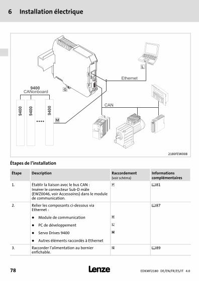
Étapes de l’installation
Étape Description Raccordement(voir schéma)
Informationscomplémentaires
1. Établir la liaison avec le bus CAN :Insérer le connecteur Sub−D mâle(EWZ0046, voir Accessoires) dans le modulede communication.
� ��81
2. Relier les composants ci−dessous viaEthernet :
��87
� Module de communication �
� PC de développement �
� Servo Drives 9400 �
� Autres éléments raccordés à Ethernet
3. Raccorder l’alimentation au bornierenfichable.
� ��89
Installation électriqueCâblage conforme CEM
6
EDKMF2180 DE/EN/FR/ES/IT 4.0 79�
H1_E_INST−SteckerFederkraftAnschluss FKCT
Câblage conforme CEM
Pour s’assurer que le câblage est conforme aux exigences à respecter en matière de CEM,vérifier les points suivants :
� Remarque importante !ƒ Séparer physiquement les câbles de commande/de données des câbles
moteur.ƒ Pour les signaux numériques, blinder les câbles de commande et de
données aux deux extrémités.ƒ Pour éviter les différences de potentiel entre les participants au bus, utiliser
une ligne de compensation d’une section minimale de 16�mm2 (référence :PE).
ƒ Respecter les autres consignes relatives à un câblage conforme CEMfournies dans la documentation de l’appareil de base.
Opérations de câblage à réaliser
1. Se conformer à la topologie du bus. Par conséquent, ne pas utiliser de câbles dedérivation.
2. Respecter les consignes et instructions de câblage comprises dans la documentationsur le maître (API).
3. Utiliser exclusivement des câbles conformes aux spécifications indiquées(��82).4. Respecter la longueur de câble bus max. admissible (��83).
5. Respecter les consignes concernant l’alimentation du module de communication(��89).
6. Activer des résistances d’extrémité de bus de 120 � au niveau du premier et dudernier participant physique au bus.
6 Installation électriqueCâblage conforme CEM
EDKMF2180 DE/EN/FR/ES/IT 4.080 �
H1_E_INST−SteckerFederkraftAnschluss FKCT
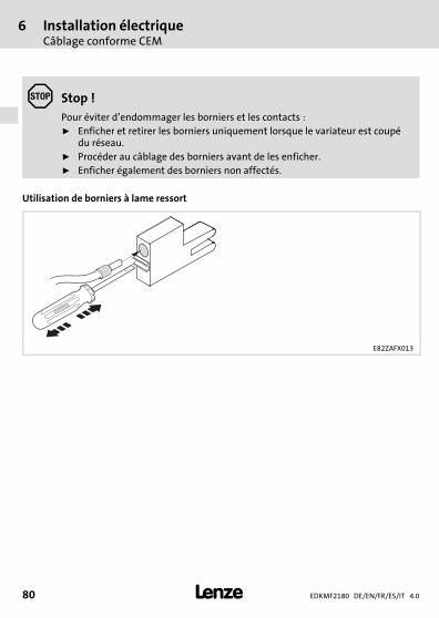
� Stop !Pour éviter d’endommager les borniers et les contacts :ƒ Enficher et retirer les borniers uniquement lorsque le variateur est coupé
du réseau.ƒ Procéder au câblage des borniers avant de les enficher.ƒ Enficher également des borniers non affectés.
Utilisation de borniers à lame ressort
E82ZAFX013
Installation électriqueRaccordement du Bus Système CAN
6
EDKMF2180 DE/EN/FR/ES/IT 4.0 81�
H1_E_INST−SteckerFederkraftAnschluss FKCT
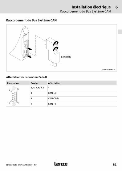
Raccordement du Bus Système CAN
2180FEW001K
Affectation du connecteur Sub−D
Illustration Broche Affectation
16
59
1, 4, 5, 6, 8, 9 −
2 CAN−LO
3 CAN−GND
7 CAN−HI
6 Installation électriqueRaccordement du Bus Système CAN
EDKMF2180 DE/EN/FR/ES/IT 4.082 �
H1_E_INST−SteckerFederkraftAnschluss FKCT
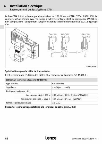
Le bus CAN doit être fermé par des résistances (120��) entre CAN−LOW et CAN−HIGH. Leconnecteur Sub−D mâle avec résistance d’extrémité intégrée (réf. de commande EWZ0046,non compris dans l’équipement livré) correspond à la recommandation DS 102−1 du groupeCiA.
L
EW
Z0046
OFF
ON
OFF
ON
ON
OFF
�
� � �
OUTIN IN IN
On Off On120 120 120
LE
WZ
00
46
LE
WZ
00
46
LE
WZ
00
46
2181FEW004
Spécifications pour le câble de transmission
Il est recommandé d’utiliser des câbles CAN conformes à la norme ISO 11898−2 :
Câbles CAN conformes à la norme ISO 11898−2
Type de câble Paire blindée
Impédance 120 � (95 ... 140 �)
Résistance/section de câble
Longueur de câble � 300 m � 70 m�/m / 0.25 � 0.34 mm2 (AWG22)
Longueur de câble 301 � 1000 m � 40 m�/m / 0.5 mm2 (AWG20)
Temps de parcours du signal � 5 ns/m
Respecter les indications relatives à la longueur du câble bus (��83)!
Installation électriqueRaccordement du Bus Système CAN
6
EDKMF2180 DE/EN/FR/ES/IT 4.0 83�
H1_E_INST−SteckerFederkraftAnschluss FKCT
Longueur de bus
� Remarque importante !ƒ Respecter impérativement les longueurs de câble autorisées!ƒ Si la longueur de câble totale pour les différents participants au bus CAN
varie, malgré une vitesse de transmission identique, la longueur de câblemaximale doit être déterminée sur la base de la plus petite valeur.
ƒ Tenir compte de la réduction de la longueur de câble totale en raison duretard du signal engendré par le répétiteur.
Longueur de câble totale
La longueur totale de câble est déterminée par la vitesse de transmission.
Vitesse de transmission [kbits/s] Longueur de câble bus max. [m]
10 7450
20 3950
50 1550
125 630
250 290
500 120
1000 25
Tab. 1 Longueur de câble totale
6 Installation électriqueRaccordement du Bus Système CAN
EDKMF2180 DE/EN/FR/ES/IT 4.084 �
H1_E_INST−SteckerFederkraftAnschluss FKCT
Longueur de câble par segment
La longueur de câble par segment est déterminée par la section de câble utilisée et lenombre de participants. Les répétiteurs subdivisent la longueur de câble totale ensegments. Sans répétiteur, la longueur de câble par segment équivaut à la longueur de câbletotale.
Nombre departicipants max.par segment
Section de câble(interpolation admise)
0.25 mm2
(AWG24)0.5 mm2
(AWG21)0.75 mm2
(AWG19)1.0 mm2
(AWG18)
2 240 m 430 m 650 m 940 m
5 230 m 420 m 640 m 920 m
10 230 m 410 m 620 m 900 m
20 210 m 390 m 580 m 850 m
32 200 m 360 m 550 m 800 m
63 170 m 310 m 470 m 690 m
100 150 m 270 m 410 m 600 m
Tab. 2 Longueur de câble par segment
Exemple : aide à la sélection
Données de base
Longueur de câble totale à réaliser 200 m
Nombre de participants 63
Résultats
Vitesse de transmission max. possible 250 kbits/s(provenant du tableau Tab. 1 Longueur de câble totale)
Section de câble requise (interpolée) 0.30 mm2 (AWG23)(provenant du tableau Tab. 2 Longueur de câble parsegment)
Section de câble standard CAN 0.34 mm2 (AWG22)(voir les spécifications du câble de transmission ��82)
Installation électriqueRaccordement du Bus Système CAN
6
EDKMF2180 DE/EN/FR/ES/IT 4.0 85�
H1_E_INST−SteckerFederkraftAnschluss FKCT
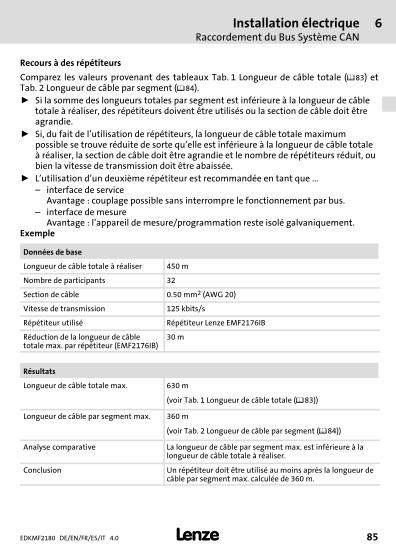
Recours à des répétiteurs
Comparez les valeurs provenant des tableaux Tab. 1 Longueur de câble totale (��83) etTab. 2 Longueur de câble par segment (��84).ƒ Si la somme des longueurs totales par segment est inférieure à la longueur de câble
totale à réaliser, des répétiteurs doivent être utilisés ou la section de câble doit êtreagrandie.
ƒ Si, du fait de l’utilisation de répétiteurs, la longueur de câble totale maximumpossible se trouve réduite de sorte qu’elle est inférieure à la longueur de câble totaleà réaliser, la section de câble doit être agrandie et le nombre de répétiteurs réduit, oubien la vitesse de transmission doit être abaissée.
ƒ L’utilisation d’un deuxième répétiteur est recommandée en tant que ...– interface de service
Avantage : couplage possible sans interrompre le fonctionnement par bus.– interface de mesure
Avantage : l’appareil de mesure/programmation reste isolé galvaniquement.Exemple
Données de base
Longueur de câble totale à réaliser 450 m
Nombre de participants 32
Section de câble 0.50 mm2 (AWG 20)
Vitesse de transmission 125 kbits/s
Répétiteur utilisé Répétiteur Lenze EMF2176IB
Réduction de la longueur de câbletotale max. par répétiteur (EMF2176IB)
30 m
Résultats
Longueur de câble totale max. 630 m
(voir Tab. 1 Longueur de câble totale (��83))
Longueur de câble par segment max. 360 m
(voir Tab. 2 Longueur de câble par segment (��84))
Analyse comparative La longueur de câble par segment max. est inférieure à lalongueur de câble totale à réaliser.
Conclusion Un répétiteur doit être utilisé au moins après la longueur decâble par segment max. calculée de 360 m.
6 Installation électriqueRaccordement du Bus Système CAN
EDKMF2180 DE/EN/FR/ES/IT 4.086 �
H1_E_INST−SteckerFederkraftAnschluss FKCT
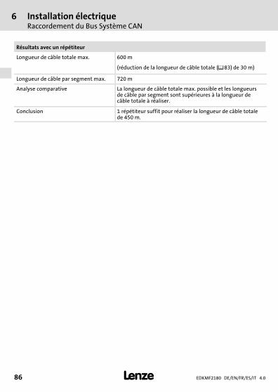
Résultats avec un répétiteur
Longueur de câble totale max. 600 m
(réduction de la longueur de câble totale (��83) de 30 m)
Longueur de câble par segment max. 720 m
Analyse comparative La longueur de câble totale max. possible et les longueursde câble par segment sont supérieures à la longueur decâble totale à réaliser.
Conclusion 1 répétiteur suffit pour réaliser la longueur de câble totalede 450 m.
Installation électriqueRaccordement Ethernet
6
EDKMF2180 DE/EN/FR/ES/IT 4.0 87�
H1_E_INST−SteckerFederkraftAnschluss FKCT
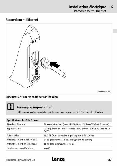
Raccordement Ethernet
2181FEW004A
Spécifications pour le câble de transmission
� Remarque importante !Utiliser exclusivement des câbles conformes aux spécifications indiquées.
Spécifications du câble Ethernet
Standard Ethernet Ethernet standard (selon IEEE 802.3), 100Base−TX (Fast Ethernet)
Type de câble S/FTP (Screened Foiled Twisted Pair), ISO/CEI 11801 ou EN 50173,CAT 5e
Atténuation 23.2 dB (pour 100 MHz et par segment de 100 m)
Affaiblissement diaphonique 24 dB (pour 100 MHz et par segment de 100 m)
Affaiblissement de régularité 10 dB (par segment de 100 m)
Impédance caractéristique 100 �
6 Installation électriqueRaccordement Ethernet
EDKMF2180 DE/EN/FR/ES/IT 4.088 �
H1_E_INST−SteckerFederkraftAnschluss FKCT
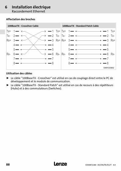
Affectation des broches
100BaseTX − CrossOver Cable 100BaseTX − Standard Patch Cable
1Tx+ Tx+1
2Tx- Tx-2
3Rx+ Rx+3
4 4
5 5
6Rx- Rx-6
7 7
8 8
1Tx+ Tx+1
2Tx- Tx-2
3Rx+ Rx+3
4 4
5 5
6Rx- Rx-6
7 7
8 8
E94YCEI002
Utilisation des câbles
ƒ Le câble "100BaseTX − CrossOver" est utilisé en cas de couplage direct entre le PC dedéveloppement et le module de communication.
ƒ Le câble "100BaseTX − Standard Patch" est utilisé en cas de recours à des répétiteurs(Hubs) et à des commutateurs (Switches).
Installation électriqueAlimentation
6
EDKMF2180 DE/EN/FR/ES/IT 4.0 89�
H1_E_INST−SteckerFederkraftAnschluss FKCT
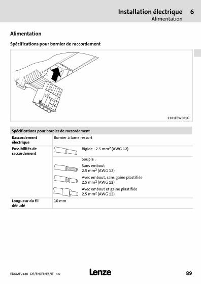
Alimentation
Spécifications pour bornier de raccordement
2181FEW001G
Spécifications pour bornier de raccordement
Raccordementélectrique
Bornier à lame ressort
Possibilités deraccordement
Rigide : 2.5 mm2 (AWG 12)
Souple :
Sans embout2.5 mm2 (AWG 12)
Avec embout, sans gaine plastifiée2.5 mm2 (AWG 12)
Avec embout et gaine plastifiée2.5 mm2 (AWG 12)
Longueur du fildénudé
10 mm
7 Mise en serviceAvant la première mise sous tension
EDKMF2180 DE/EN/FR/ES/IT 4.090 �
H1inbet−LESE_INB_KHB_Fernwartung
7 Mise en service
Avant la première mise sous tension
� Stop !Avant la mise sous tension, contrôler l’ensemble du câblage et rechercherd’éventuels courts−circuits ou défauts de mise à la terre.
� Manuel de communication EMF2180IB (EthernetCAN)
Consulter ce document pour trouver des informations détaillées sur la mise enservice.
DiagnosticAffichages d’état par LED
8
EDKMF2180 DE/EN/FR/ES/IT 4.0 91�
H1_Diagnose−st_00tu0
8 Diagnostic
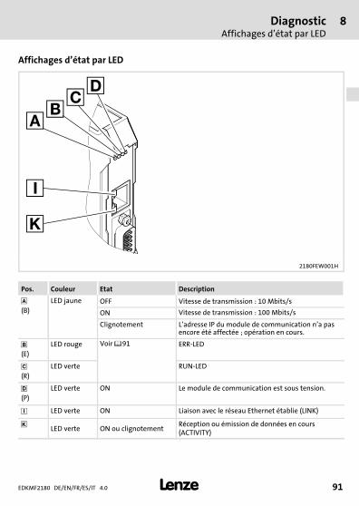
Affichages d’état par LED
2180FEW001H
Pos. Couleur Etat Description
(B)
LED jaune OFF Vitesse de transmission : 10 Mbits/s
ON Vitesse de transmission : 100 Mbits/s
Clignotement L’adresse IP du module de communication n’a pasencore été affectée ; opération en cours.
�(E)
LED rouge Voir ��91 ERR−LED
�(R)
LED verte RUN−LED
(P)
LED verte ON Le module de communication est sous tension.
� LED verte ON Liaison avec le réseau Ethernet établie (LINK)
� LED verte ON ou clignotementRéception ou émission de données en cours(ACTIVITY)
8 DiagnosticAffichages d’état par LED
EDKMF2180 DE/EN/FR/ES/IT 4.092 �
H1_Diagnose−st_00tu0
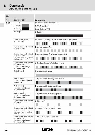
LED
DescriptionPos. Couleur / état
��/ � OFF Liaison avec le maître non établie
LED verte État CANopen ("Z")
LED rouge Erreur CANopen ("F")
LED rouge Z : Bus Off
Clignotement rapide(scintillement)
Détection automatique de la vitesse de transmission activée
Clignotement (vert) suivantun cycle de 0.2 s
Z : Pre−Operational, F : −
Clignotement (vert) suivantun cycle de 0.2 s1 clignotement (rouge), rienpendant 1 s
Z : Pre−Operational, F : Warning Limit reached
Clignotement (vert) suivantun cycle de 0.2 s2 clignotements (rouge),rien pendant 1 s
Z : Pre−Operational, F : Node Guard Event
ON (LED verte) Z : Operational, F : keine
ON (LED verte)1 clignotement (rouge), rienpendant 1 s
Z : Operational, F : Warning Limit reached
ON (LED verte)2 clignotements (rouge),rien pendant 1 s
Z : Operational, F : Node Guard Event
ON (LED verte)3 clignotements (rouge),rien pendant 1 s
Z : Operational, F : Sync Message Error
Clignotement (vert) suivantun cycle de 1 s
Z : Stopped, F : −
Clignotement (vert) suivantun cycle de 1 s1 clignotement (rouge), rienpendant 1 s
Z : Stopped, F : Warning Limit reached
Clignotement (vert) suivantun cycle de 1 s2 clignotements (rouge),rien pendant 1 s
Z : Stopped, F : Node Guard Event
DiagnosticAffichages d’état par LED
8
EDKMF2180 DE/EN/FR/ES/IT 4.0 93�
H1_Diagnose−st_00tu0

EDKMF2180 DE/EN/FR/ES/IT 4.094 �
legende_kopfzeile−DUMMY_NUM_Reset
Leyenda de la ilustración del lado abatible
Pos. Descripción Informacióndetallada
� Conexión a Ethernet� Conector hembra RJ45
��116
� Conexión CAN� Conector hembra Sub−D de 9 polos
��110
� Conexión para la alimentación de voltaje� Regleta de conectores de 4 polos con conexión por fuerza de resorte
��118
Conexión PE� La conexión PE se realiza a través del riel de perfil de sombrero. Para ello,
el módulo de comunicaciones se debe insertar en el riel de perfil desombrero y este debe estar conectado con PE.
Indicaciones de estado por LED para el diagnóstico ��120
�
�
�
�0Fig. 0Tab. 0

Contenido i
EDKMF2180 DE/EN/FR/ES/IT 4.0 95�
Inhalt
1 Acerca de esta documentación 96. . . . . . . . . . . . . . . . . . . . . . . . . . . . . . . . . . . . . . . . . Convenciones utilizadas 97. . . . . . . . . . . . . . . . . . . . . . . . . . . . . . . . . . . . . . . . . . . . . . Indicaciones utilizadas 98. . . . . . . . . . . . . . . . . . . . . . . . . . . . . . . . . . . . . . . . . . . . . . . .
2 Instrucciones de seguridad 99. . . . . . . . . . . . . . . . . . . . . . . . . . . . . . . . . . . . . . . . . . . .
3 Descripción del producto 100. . . . . . . . . . . . . . . . . . . . . . . . . . . . . . . . . . . . . . . . . . . . . Función 100. . . . . . . . . . . . . . . . . . . . . . . . . . . . . . . . . . . . . . . . . . . . . . . . . . . . . . . . . . . . Uso previsto 100. . . . . . . . . . . . . . . . . . . . . . . . . . . . . . . . . . . . . . . . . . . . . . . . . . . . . . . Volumen de suministro 100. . . . . . . . . . . . . . . . . . . . . . . . . . . . . . . . . . . . . . . . . . . . . . . Identificación 101. . . . . . . . . . . . . . . . . . . . . . . . . . . . . . . . . . . . . . . . . . . . . . . . . . . . . . .
4 Datos técnicos 102. . . . . . . . . . . . . . . . . . . . . . . . . . . . . . . . . . . . . . . . . . . . . . . . . . . . . . Datos generales y condiciones de uso 102. . . . . . . . . . . . . . . . . . . . . . . . . . . . . . . . . . Aislamiento de protección 103. . . . . . . . . . . . . . . . . . . . . . . . . . . . . . . . . . . . . . . . . . . . Dimensiones 104. . . . . . . . . . . . . . . . . . . . . . . . . . . . . . . . . . . . . . . . . . . . . . . . . . . . . . . .
5 Instalación mecánica 105. . . . . . . . . . . . . . . . . . . . . . . . . . . . . . . . . . . . . . . . . . . . . . . . .
6 Instalación eléctrica 107. . . . . . . . . . . . . . . . . . . . . . . . . . . . . . . . . . . . . . . . . . . . . . . . . . Cableado correcto CEM 108. . . . . . . . . . . . . . . . . . . . . . . . . . . . . . . . . . . . . . . . . . . . . . . Conectar Systembus (CAN) 110. . . . . . . . . . . . . . . . . . . . . . . . . . . . . . . . . . . . . . . . . . . . Conexión a Ethernet 116. . . . . . . . . . . . . . . . . . . . . . . . . . . . . . . . . . . . . . . . . . . . . . . . . Alimentación de voltaje 118. . . . . . . . . . . . . . . . . . . . . . . . . . . . . . . . . . . . . . . . . . . . . .
7 Puesta en marcha 119. . . . . . . . . . . . . . . . . . . . . . . . . . . . . . . . . . . . . . . . . . . . . . . . . . . . Antes de la primera conexión 119. . . . . . . . . . . . . . . . . . . . . . . . . . . . . . . . . . . . . . . . . .
8 Diagnóstico 120. . . . . . . . . . . . . . . . . . . . . . . . . . . . . . . . . . . . . . . . . . . . . . . . . . . . . . . . . Indicadores de estado LED 120. . . . . . . . . . . . . . . . . . . . . . . . . . . . . . . . . . . . . . . . . . . .
1 Acerca de esta documentación
EDKMF2180 DE/EN/FR/ES/IT 4.096 �
H1_Über_die_Doku−TIP_download_DE
1 Acerca de esta documentación
Contenido
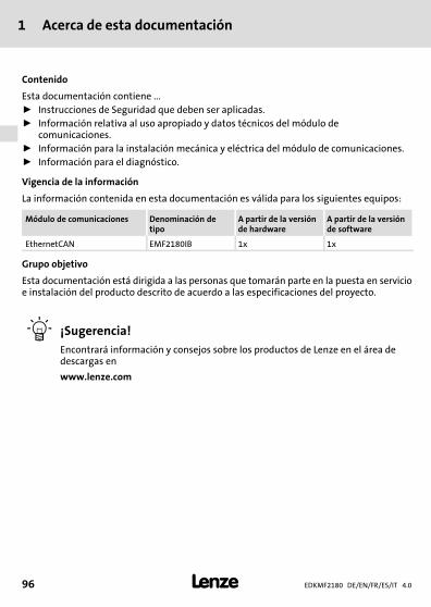
Esta documentación contiene ...ƒ Instrucciones de Seguridad que deben ser aplicadas.ƒ Información relativa al uso apropiado y datos técnicos del módulo de
comunicaciones.ƒ Información para la instalación mecánica y eléctrica del módulo de comunicaciones.ƒ Información para el diagnóstico.
Vigencia de la información
La información contenida en esta documentación es válida para los siguientes equipos:
Módulo de comunicaciones Denominación detipo
A partir de la versiónde hardware
A partir de la versiónde software
EthernetCAN EMF2180IB 1x 1x
Grupo objetivo
Esta documentación está dirigida a las personas que tomarán parte en la puesta en servicioe instalación del producto descrito de acuerdo a las especificaciones del proyecto.
� ¡Sugerencia!Encontrará información y consejos sobre los productos de Lenze en el área dedescargas en
www.lenze.com
Acerca de esta documentaciónConvenciones utilizadas
1
EDKMF2180 DE/EN/FR/ES/IT 4.0 97�
H2_Verw_Konventionen−Verw_Konv_MA_KommModule
Convenciones utilizadas
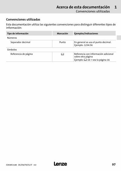
Esta documentación utiliza las siguientes convenciones para distinguir diferentes tipos deinformación:
Tipo de información Marcación Ejemplos/indicaciones
Números
Separador decimal Punto En general se usa el punto decimal.Ejemplo: 1234.56
Símbolos
Referencia de página � Referencia con información adicionalsobre otra páginaEjemplo: � 16 = vea la página 16

1 Acerca de esta documentaciónIndicaciones utilizadas
EDKMF2180 DE/EN/FR/ES/IT 4.098 �
H2_Def_Hinweise−SIC_pikt_ES
Indicaciones utilizadas
Para indicar peligros e información importante, se utilizan en esta documentación lossiguientes términos indicativos y símbolos:
Instrucciones de seguridad
Estructura de las instrucciones de seguridad:
� ¡Peligro!(indican el tipo y la gravedad del peligro)
Texto indicativo
(describe el peligro y da instrucciones para evitarlo)
Pictograma y término indicativo Significado
� ¡Peligro!Riesgo de daños personales por voltaje eléctricoIndica un peligro inminente que puede causar la muerte olesiones graves si no se toman las medidas adecuadas.
� ¡Peligro!
Riesgo de daños personales por una fuente de riesgogeneralIndica un peligro inminente que puede causar la muerte olesiones graves si no se toman las medidas adecuadas.
� ¡Alto!Peligro de daños materialesIndica un posible riesgo que puede ocasionar dañosmateriales si no se toman las medidas adecuadas.
Instrucciones de uso
Pictograma y término indicativo Significado
� ¡Aviso! Nota importante para el funcionamiento sin fallos
� ¡Sugerencia! Sugerencia útil para facilitar la operación
� Referencia a otra documentación
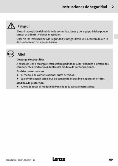
Instrucciones de seguridad 2
EDKMF2180 DE/EN/FR/ES/IT 4.0 99�
H1sic_ES−stop_statEntlad_KommModule
2 Instrucciones de seguridad
� ¡Peligro!El uso inapropiado del módulo de comunicaciones y del equipo básico puedecausar accidentes y daños materiales.
Observe las Instrucciones de Seguridad y Riesgos Residuales contenidos en ladocumentación del equipo básico.
� ¡Alto!Descarga electrostática
A causa de una descarga electrostática podrían resultar dañados o destruidoscomponentes electrónicos dentro del módulo de comunicaciones.
Posibles consecuenciasƒ El módulo de comunicaciones sufre defectos.ƒ La comunicación con el bus de campo no es posible o aparecen errores.
Medidas de protecciónƒ Antes de tocar el módulo libérese de toda carga electrostática.
3 Descripción del productoFunción
EDKMF2180 DE/EN/FR/ES/IT 4.0100 �
−H1−typbez
3 Descripción del producto
Función
El módulo de comunicaciones se utiliza a través de mantenimiento remoto para laparametrización o programación, puesta en marcha y diagnóstico de los equipos Lenzeutilizables.
Uso previsto
El módulo de comunicaciones se puede utilizar con los siguientes equipos Lenze:ƒ Servo Drives 9400ƒ Inverter Drives 8400ƒ Servoconvertidor 9300ƒ 9300 vectorƒ 9300 Servo PLCƒ Servosistema ECSƒ Convertidor de motor 8200 motecƒ Convertidor de frecuencia 8200 vectorƒ Convertidor de frecuencia 82XXƒ Drive PLCƒ Ampliación de bornes 9374ƒ Unidad de operación y visualización (EPM−HXXX)ƒ I/O−System IP20 (EPM−TXXX)
Volumen de suministro
ƒ Módulo de comunicaciones EMF2180IB (EthernetCAN)ƒ Instrucciones para el montaje
� Manual de comunicación EMF2180IB (EthernetCAN)
Aquí encontrará más información al respecto.
Encontrará el archivo PDF en el área de descargas en www.lenze.com.
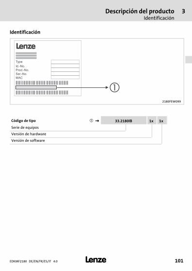
Descripción del productoIdentificación
3
EDKMF2180 DE/EN/FR/ES/IT 4.0 101�
−H1−typbez
Identificación
2180FEW099
Código de tipo ���� 33.2180IB 1x 1x
Serie de equipos
Versión de hardware
Versión de software
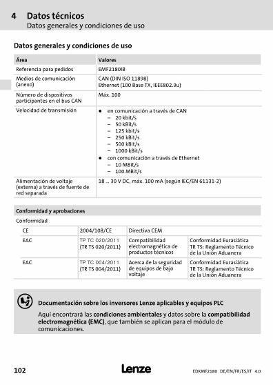
4 Datos técnicosDatos generales y condiciones de uso
EDKMF2180 DE/EN/FR/ES/IT 4.0102 �
H1_Daten−TabAbmess
4 Datos técnicos
Datos generales y condiciones de uso
Área Valores
Referencia para pedidos EMF2180IB
Medios de comunicación(anexo)
CAN (DIN ISO 11898)Ethernet (100 Base TX, IEEE802.3u)
Número de dispositivosparticipantes en el bus CAN
Máx. 100
Velocidad de transmisión � en comunicación a través de CAN– 20 kbit/s– 50 kBit/s– 125 kbit/s– 250 kBit/s– 500 kBit/s– 1000 kBit/s
� con comunicación a través de Ethernet– 10 MBit/s– 100 MBit/s
Alimentación de voltaje(externa) a través de fuente dered separada
18 � 30 V DC, máx. 100 mA (según IEC/EN 61131−2)
Conformidad y aprobaciones
Conformidad
CE 2004/108/CE Directiva CEM
EAC ������������
(TR TS 020/2011)Compatibilidadelectromagnética deproductos técnicos
Conformidad EurasiáticaTR TS: Reglamento Técnicode la Unión Aduanera
EAC �����������
(TR TS 004/2011)Acerca de la seguridadde equipos de bajovoltaje
Conformidad EurasiáticaTR TS: Reglamento Técnicode la Unión Aduanera
� Documentación sobre los inversores Lenze aplicables y equipos PLC
Aquí encontrará las condiciones ambientales y datos sobre la compatibilidadelectromagnética (EMC), que también se aplican para el módulo decomunicaciones.
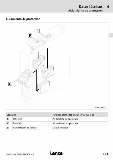
Datos técnicosAislamiento de protección
4
EDKMF2180 DE/EN/FR/ES/IT 4.0 103�
H1_Daten−TabAbmess
Aislamiento de protección
2180FEW001F
Conexión Tipo de aislamiento (según EN 61800−5−1)
� Ethernet Aislamiento de operación
� Bus CAN Aislamiento de operación
� Alimentación de voltaje Sin aislamiento
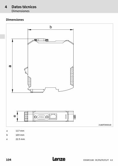
4 Datos técnicosDimensiones
EDKMF2180 DE/EN/FR/ES/IT 4.0104 �
H1_Daten−TabAbmess
Dimensiones
2180FEW001B
a 117 mm
b 103 mm
e 22.5 mm
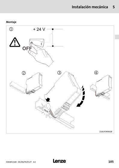
Instalación mecánica 5
EDKMF2180 DE/EN/FR/ES/IT 4.0 105�
H1_MechINS−218x entriegeln
5 Instalación mecánica
Montaje
2181FEW002B
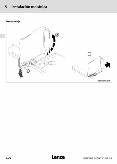
5 Instalación mecánica
EDKMF2180 DE/EN/FR/ES/IT 4.0106 �
H1_MechINS−218x entriegeln
Desmontaje
2181FEW001E

Instalación eléctrica 6
EDKMF2180 DE/EN/FR/ES/IT 4.0 107�
H1_E_INST−SteckerFederkraftAnschluss FKCT
6 Instalación eléctrica
2180FEW008
Pasos para la instalación
Paso Acción Conexión(ver gráfico)
Informaciónadicional
1. Establecer conexión con el bus CAN:conectar el enchufe Sub−D («EWZ0046», veraccesorios) al módulo de comunicaciones.
� ��110
2. Conectar los siguientes componentes através de Ethernet:
��116
� Módulo de comunicaciones �
� Engineering PC �
� Servo Drives 9400 �
� otros participantes de Ethernet
3. Conectar alimentación de voltaje a laregleta de enchufes.
� ��118
6 Instalación eléctricaCableado correcto CEM
EDKMF2180 DE/EN/FR/ES/IT 4.0108 �
H1_E_INST−SteckerFederkraftAnschluss FKCT
Cableado correcto CEM
Para conseguir un cableado adecuado para la CEM deben tenerse en cuenta los puntossiguientes:
� ¡Aviso!ƒ Colocar los cables de control / datos separados de los cables de motor.ƒ En el caso de señales digitales, aplicar las mallas de los cables de control /
datos a ambos lados.ƒ Para evitar diferencias de potencial entre los dispositivos de comunicación
deberá utilizarse un cable de compensación con una sección de por lomenos 16�mm2 (referencia:�PE).
ƒ Observe otras indicaciones sobre el cableado apropiado para la CEM en ladocumentación del equipo básico.
Procedimiento para el cableado
1. Respetar la tipología del bus y en consecuencia no utilizar cable de derivación.2. Observar las indicaciones y normas de cableado en la documentación del ordenador
central (PLC).3. Utilizar solo cables que cumplan con las especificaciones indicadas (��111).4. Respetar la longitud de cable de bus permitida (��112).
5. Observar las indicaciones sobre la alimentación de tensión del módulo decomunicaciones (��118).
6. Activar las resistencias finales de bus de 120 � en el primer y último dispositivo físicode bus.
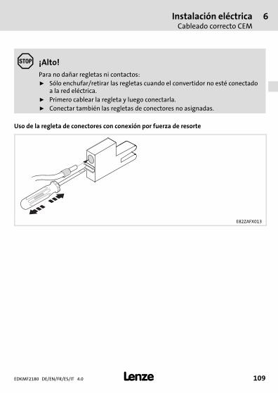
Instalación eléctricaCableado correcto CEM
6
EDKMF2180 DE/EN/FR/ES/IT 4.0 109�
H1_E_INST−SteckerFederkraftAnschluss FKCT
� ¡Alto!Para no dañar regletas ni contactos:ƒ Sólo enchufar/retirar las regletas cuando el convertidor no esté conectado
a la red eléctrica.ƒ Primero cablear la regleta y luego conectarla.ƒ Conectar también las regletas de conectores no asignadas.
Uso de la regleta de conectores con conexión por fuerza de resorte
E82ZAFX013
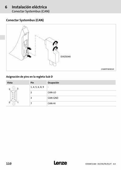
6 Instalación eléctricaConectar Systembus (CAN)
EDKMF2180 DE/EN/FR/ES/IT 4.0110 �
H1_E_INST−SteckerFederkraftAnschluss FKCT
Conectar Systembus (CAN)
2180FEW001K
Asignación de pins en la regleta Sub D
Vista Pin Ocupación
16
59
1, 4, 5, 6, 8, 9 −
2 CAN−LO
3 CAN−GND
7 CAN−HI
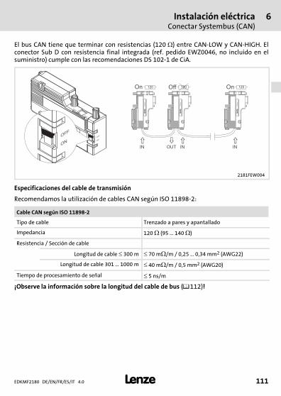
Instalación eléctricaConectar Systembus (CAN)
6
EDKMF2180 DE/EN/FR/ES/IT 4.0 111�
H1_E_INST−SteckerFederkraftAnschluss FKCT
El bus CAN tiene que terminar con resistencias (120��) entre CAN−LOW y CAN−HIGH. Elconector Sub D con resistencia final integrada (ref. pedido EWZ0046, no incluido en elsuministro) cumple con las recomendaciones DS 102−1 de CiA.
L
EW
Z0046
OFF
ON
OFF
ON
ON
OFF
�
� � �
OUTIN IN IN
On Off On120 120 120
LE
WZ
00
46
LE
WZ
00
46
LE
WZ
00
46
2181FEW004
Especificaciones del cable de transmisión
Recomendamos la utilización de cables CAN según ISO 11898−2:
Cable CAN según ISO 11898−2
Tipo de cable Trenzado a pares y apantallado
Impedancia 120 � (95 ... 140 �)
Resistencia / Sección de cable
Longitud de cable � 300 m � 70 m�/m / 0,25 � 0,34 mm2 (AWG22)
Longitud de cable 301 � 1000 m � 40 m�/m / 0,5 mm2 (AWG20)
Tiempo de procesamiento de señal � 5 ns/m
¡Observe la información sobre la longitud del cable de bus (��112)!
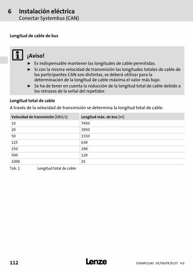
6 Instalación eléctricaConectar Systembus (CAN)
EDKMF2180 DE/EN/FR/ES/IT 4.0112 �
H1_E_INST−SteckerFederkraftAnschluss FKCT
Longitud de cable de bus
� ¡Aviso!ƒ Es indispensable mantener las longitudes de cable permitidas.ƒ Si con la misma velocidad de transmisión las longitudes totales de cable de
los participantes CAN son distintas, se deberá utilizar para ladeterminación de la longitud de cable máxima el valor más bajo.
ƒ Se ha de tener en cuenta la reducción de la longitud total de cable debido alos retrasos de la señal del repetidor.
Longitud total de cable
A través de la velocidad de transmisión se determina la longitud total de cable.
Velocidad de transmisión [kBit/s] Longitud máx. de bus [m]
10 7450
20 3950
50 1550
125 630
250 290
500 120
1000 25
Tab. 1 Longitud total de cable
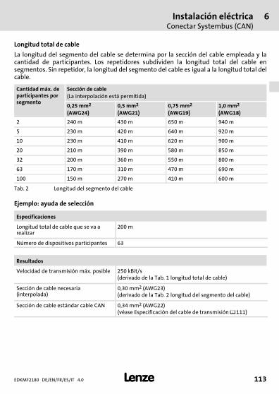
Instalación eléctricaConectar Systembus (CAN)
6
EDKMF2180 DE/EN/FR/ES/IT 4.0 113�
H1_E_INST−SteckerFederkraftAnschluss FKCT
Longitud total de cable
La longitud del segmento del cable se determina por la sección del cable empleada y lacantidad de participantes. Los repetidores subdividen la longitud total del cable ensegmentos. Sin repetidor, la longitud del segmento del cable es igual a la longitud total delcable.
Cantidad máx. departicipantes porsegmento
Sección de cable(La interpolación está permitida)
0,25 mm2
(AWG24)0,5 mm2
(AWG21)0,75 mm2
(AWG19)1,0 mm2
(AWG18)
2 240 m 430 m 650 m 940 m
5 230 m 420 m 640 m 920 m
10 230 m 410 m 620 m 900 m
20 210 m 390 m 580 m 850 m
32 200 m 360 m 550 m 800 m
63 170 m 310 m 470 m 690 m
100 150 m 270 m 410 m 600 m
Tab. 2 Longitud del segmento del cable
Ejemplo: ayuda de selección
Especificaciones
Longitud total de cable que se va arealizar
200 m
Número de dispositivos participantes 63
Resultados
Velocidad de transmisión máx. posible 250 kBit/s(derivado de la Tab. 1 longitud total de cable)
Sección de cable necesaria(interpolada)
0,30 mm2 (AWG23)(derivado de la Tab. 2 longitud del segmento del cable)
Sección de cable estándar cable CAN 0,34 mm2 (AWG22)(véase Especificación del cable de transmisión ��111)
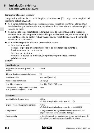
6 Instalación eléctricaConectar Systembus (CAN)
EDKMF2180 DE/EN/FR/ES/IT 4.0114 �
H1_E_INST−SteckerFederkraftAnschluss FKCT
Comprobar el uso del repetidor
Compare los valores de la Tab. 1 longitud total de cable (��112) y Tab. 2 longitud delsegmento del cable(��113).ƒ Si la suma de las longitudes de los segmentos de los cables es inferior a la longitud
total de cable que se debe efectuar, se deben utilizar repetidores o se ha de ampliar lasección de cable.
ƒ Si, debido al uso de repetidores, la longitud total de cable máx. posible se reducesiendo inferior a la longitud total de cable que ha de efectuarse, entonces habrá queampliar la sección de cable y reducir la cantidad de repetidores o, bien, disminuir lavelocidad de transmisión.
ƒ El uso de un repetidor adicional se recomienda como...– Interface de servicio
Ventaja: es posible un acoplamiento libre de interferencias durante elfuncionamiento de bus en curso.
– Interface de mediciónVentajas: el equipo de medición/programación permanece separadogalvánicamente.
Ejemplo
Especificaciones
Longitud total de cable que se va arealizar
450 m
Número de dispositivos participantes 32
Sección de cable 0,50 mm2 (AWG 20)
Velocidad de transmisión 125 kbit/s
Repetidor empleado Repetidor EMF2176IB Lenze
Reducción de la longitud total de cablemáx. por repetidor (EMF2176IB)
30 m
Resultados
Longitud total de cable máx. 630 m(cfr. Tab. 1 Longitud total de cable (��112))
longitud máx. del segmento del cable 360 m(cfr. Tab. 2 Longitud del segmento del cable (��113))
Comparación La longitud máx. del segmento del cable es inferior a lalongitud total de cable que se ha de lograr.
Consecuencia Se debe introducir un repetidor como muy tarde después dela longitud máx. del segmento de cable de 360 m.
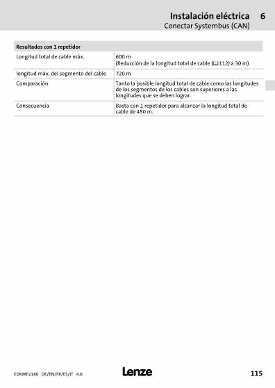
Instalación eléctricaConectar Systembus (CAN)
6
EDKMF2180 DE/EN/FR/ES/IT 4.0 115�
H1_E_INST−SteckerFederkraftAnschluss FKCT
Resultados con 1 repetidor
Longitud total de cable máx. 600 m(Reducción de la longitud total de cable (��112) a 30 m)
longitud máx. del segmento del cable 720 m
Comparación Tanto la posible longitud total de cable como las longitudesde los segmentos de los cables son superiores a laslongitudes que se deben lograr.
Consecuencia Basta con 1 repetidor para alcanzar la longitud total decable de 450 m.
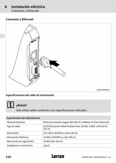
6 Instalación eléctricaConexión a Ethernet
EDKMF2180 DE/EN/FR/ES/IT 4.0116 �
H1_E_INST−SteckerFederkraftAnschluss FKCT
Conexión a Ethernet
2181FEW004A
Especificaciones del cable de transmisión
� ¡Aviso!Sólo utilice cables conforme a las especificaciones indicadas.
Especificación del cable Ethernet
Ethernet Estándar Ethernet estándar (según IEEE 802.3), 100Base−TX (Fast Ethernet)
Tipo de cable S/FTP (Screened Foiled Twisted Pair), ISO/IEC 11801 o EN 50173,CAT 5e
Atenuación 23.2 dB (a 100 MHz y cada 100 m)
Atenuación diafónica 24 dB (a 100 MHz y cada 100 m)
Atenuación de regularidad 10 dB (cada 100 m)
Impedancia característica 100 �

Instalación eléctricaConexión a Ethernet
6
EDKMF2180 DE/EN/FR/ES/IT 4.0 117�
H1_E_INST−SteckerFederkraftAnschluss FKCT
Asignación de pins
100BaseTX − CrossOver Cable 100BaseTX − Standard Patch Cable
1Tx+ Tx+1
2Tx- Tx-2
3Rx+ Rx+3
4 4
5 5
6Rx- Rx-6
7 7
8 8
1Tx+ Tx+1
2Tx- Tx-2
3Rx+ Rx+3
4 4
5 5
6Rx- Rx-6
7 7
8 8
E94YCEI002
Uso de los cables
ƒ El "100BaseTX − CrossOver Cable" se utiliza para el acoplamiento directo delEngineering PC con el módulo de comunicaciones.
ƒ El cable "100BaseTX − Standard Patch Cable"se utiliza con hubs y switches.
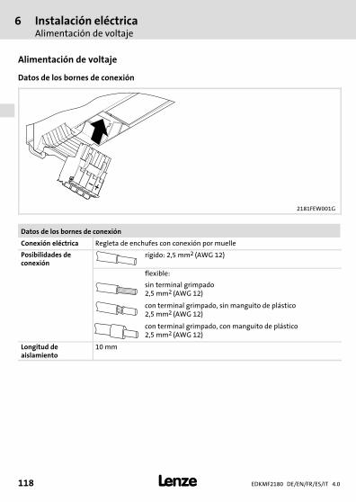
6 Instalación eléctricaAlimentación de voltaje
EDKMF2180 DE/EN/FR/ES/IT 4.0118 �
H1_E_INST−SteckerFederkraftAnschluss FKCT
Alimentación de voltaje
Datos de los bornes de conexión
2181FEW001G
Datos de los bornes de conexión
Conexión eléctrica Regleta de enchufes con conexión por muelle
Posibilidades deconexión
rígido: 2,5 mm2 (AWG 12)
flexible:
sin terminal grimpado2,5 mm2 (AWG 12)
con terminal grimpado, sin manguito de plástico2,5 mm2 (AWG 12)
con terminal grimpado, con manguito de plástico2,5 mm2 (AWG 12)
Longitud deaislamiento
10 mm
Puesta en marchaAntes de la primera conexión
7
EDKMF2180 DE/EN/FR/ES/IT 4.0 119�
H1inbet−LESE_INB_KHB_Fernwartung
7 Puesta en marcha
Antes de la primera conexión
� ¡Alto!Antes de conectar la alimentación de voltaje compruebe que todo el cableadoesté completo y protegido contra cortocircuitos y contactos a tierra.
� Manual de comunicación EMF2180IB (EthernetCAN)
Aquí encontrará información detallada sobre la puesta en marcha.
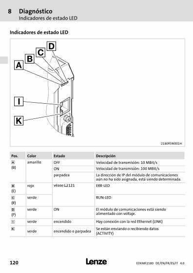
8 DiagnósticoIndicadores de estado LED
EDKMF2180 DE/EN/FR/ES/IT 4.0120 �
H1_Diagnose−st_00tu0
8 Diagnóstico
Indicadores de estado LED
2180FEW001H
Pos. Color Estado Descripción
(B)
amarillo OFF Velocidad de transmisión: 10 MBit/s
ON Velocidad de transmisión: 100 MBit/s
parpadea La dirección de IP del módulo de comunicacionesaún no ha sido asignada, está siendo determinada.
�(E)
rojo véase ��121 ERR−LED
�(R)
verde RUN−LED
(P)
verde ON El módulo de comunicaciones está siendoalimentado con voltaje.
� verde encendido Hay conexión con la red Ethernet (LINK)
� verde encendido o parpadeaSe están enviando o recibiendo datos(ACTIVITY)
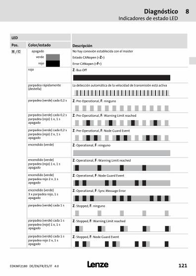
DiagnósticoIndicadores de estado LED
8
EDKMF2180 DE/EN/FR/ES/IT 4.0 121�
H1_Diagnose−st_00tu0
LED
DescripciónPos. Color/estado
��/ � apagado No hay conexión establecida con el master
verde Estado CANopen («Z»)
rojo Error CANopen («F»)
rojo Z: Bus Off
parpadea rápidamente(destella)
La detección automática de la velocidad de transmisión está activa
parpadea (verde) cada 0,2 s Z: Pre−Operational, F: ninguno
parpadea (verde) cada 0,2 sparpadea (rojo) 1 x, 1 sapagado
Z: Pre−Operational, F: Warning Limit reached
parpadea (verde) cada 0,2 sparpadea (rojo) 2 x, 1 sapagado
Z: Pre−Operational, F: Node Guard Event
encendido (verde) Z: Operational, F: ninguno
encendido (verde)parpadea (rojo) 1 x, 1 sapagado
Z: Operational, F: Warning Limit reached
encendido (verde)parpadea rojo 2 x ,1 sapagado
Z: Operational, F: Node Guard Event
encendido (verde)3 x parpadea rojo, 1 sapagado
Z: Operational, F: Sync Message Error
parpadea (verde) cada 1 s Z: Stopped, F: ninguno
parpadea (verde) cada 1 sparpadea (rojo) 1 x, 1 sapagado
Z: Stopped, F: Warning Limit reached
parpadea (verde) cada 1 sparpadea rojo 2 x, 1 sapagado
Z: Stopped, F: Node Guard Event

EDKMF2180 DE/EN/FR/ES/IT 4.0122 �
legende_kopfzeile−DUMMY_NUM_Reset
Legenda figura su pagina ripiegata
Pos. Descrizione Informazionidettagliate
� Collegamento Ethernet� Connettore RJ45
��144
� Connessione CAN� Connettore femmina Sub−D a 9 poli
��138
� Collegamento per alimentazione� Morsettiera estraibile con collegamento a molla a 4 poli
��146
Collegamento PE� Il collegamento PE avviene tramite la guida DIN. Il modulo di
comunicazione deve quindi essere inserito sulla guida DIN e quest’ultimadeve essere collegata al PE!
Indicatori di stato a LED per la diagnostica ��148
�
�
�
�0Fig. 0Tab. 0
Sommario i
EDKMF2180 DE/EN/FR/ES/IT 4.0 123�
Inhalt
1 Informazioni sul manuale 124. . . . . . . . . . . . . . . . . . . . . . . . . . . . . . . . . . . . . . . . . . . . . Convenzioni utilizzate 125. . . . . . . . . . . . . . . . . . . . . . . . . . . . . . . . . . . . . . . . . . . . . . . . Avvertenze utilizzate 126. . . . . . . . . . . . . . . . . . . . . . . . . . . . . . . . . . . . . . . . . . . . . . . . .
2 Informazioni sulla sicurezza 127. . . . . . . . . . . . . . . . . . . . . . . . . . . . . . . . . . . . . . . . . . .
3 Descrizione del prodotto 128. . . . . . . . . . . . . . . . . . . . . . . . . . . . . . . . . . . . . . . . . . . . . Funzione 128. . . . . . . . . . . . . . . . . . . . . . . . . . . . . . . . . . . . . . . . . . . . . . . . . . . . . . . . . . . Utilizzo conforme 128. . . . . . . . . . . . . . . . . . . . . . . . . . . . . . . . . . . . . . . . . . . . . . . . . . . Oggetto della fornitura 128. . . . . . . . . . . . . . . . . . . . . . . . . . . . . . . . . . . . . . . . . . . . . . . Identificazione 129. . . . . . . . . . . . . . . . . . . . . . . . . . . . . . . . . . . . . . . . . . . . . . . . . . . . . .
4 Dati tecnici 130. . . . . . . . . . . . . . . . . . . . . . . . . . . . . . . . . . . . . . . . . . . . . . . . . . . . . . . . . Dati generali e condizioni di impiego 130. . . . . . . . . . . . . . . . . . . . . . . . . . . . . . . . . . Isolamento di protezione 131. . . . . . . . . . . . . . . . . . . . . . . . . . . . . . . . . . . . . . . . . . . . . Dimensioni 132. . . . . . . . . . . . . . . . . . . . . . . . . . . . . . . . . . . . . . . . . . . . . . . . . . . . . . . . .
5 Installazione meccanica 133. . . . . . . . . . . . . . . . . . . . . . . . . . . . . . . . . . . . . . . . . . . . . . .
6 Installazione elettrica 135. . . . . . . . . . . . . . . . . . . . . . . . . . . . . . . . . . . . . . . . . . . . . . . . Cablaggio conforme EMC 136. . . . . . . . . . . . . . . . . . . . . . . . . . . . . . . . . . . . . . . . . . . . . Collegamento del system bus (CAN) 138. . . . . . . . . . . . . . . . . . . . . . . . . . . . . . . . . . . . Collegamento Ethernet 144. . . . . . . . . . . . . . . . . . . . . . . . . . . . . . . . . . . . . . . . . . . . . . . Alimentazione 146. . . . . . . . . . . . . . . . . . . . . . . . . . . . . . . . . . . . . . . . . . . . . . . . . . . . . .
7 Messa in servizio 147. . . . . . . . . . . . . . . . . . . . . . . . . . . . . . . . . . . . . . . . . . . . . . . . . . . . Prima dell’accensione 147. . . . . . . . . . . . . . . . . . . . . . . . . . . . . . . . . . . . . . . . . . . . . . . .
8 Diagnostica 148. . . . . . . . . . . . . . . . . . . . . . . . . . . . . . . . . . . . . . . . . . . . . . . . . . . . . . . . . Indicatori di stato a LED 148. . . . . . . . . . . . . . . . . . . . . . . . . . . . . . . . . . . . . . . . . . . . . .
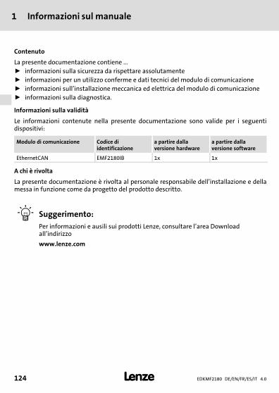
1 Informazioni sul manuale
EDKMF2180 DE/EN/FR/ES/IT 4.0124 �
H1_Über_die_Doku−TIP_download_DE
1 Informazioni sul manuale
Contenuto
La presente documentazione contiene ...ƒ informazioni sulla sicurezza da rispettare assolutamenteƒ informazioni per un utilizzo conferme e dati tecnici del modulo di comunicazioneƒ informazioni sull’installazione meccanica ed elettrica del modulo di comunicazioneƒ informazioni sulla diagnostica.
Informazioni sulla validità
Le informazioni contenute nella presente documentazione sono valide per i seguentidispositivi:
Modulo di comunicazione Codice diidentificazione
a partire dallaversione hardware
a partire dallaversione software
EthernetCAN EMF2180IB 1x 1x
A chi è rivolta
La presente documentazione è rivolta al personale responsabile dell’installazione e dellamessa in funzione come da progetto del prodotto descritto.
� Suggerimento:Per informazioni e ausili sui prodotti Lenze, consultare l’area Downloadall’indirizzo
www.lenze.com
Informazioni sul manualeConvenzioni utilizzate
1
EDKMF2180 DE/EN/FR/ES/IT 4.0 125�
H2_Verw_Konventionen−Verw_Konv_MA_KommModule
Convenzioni utilizzate
La presente documentazione utilizza le seguenti convenzioni tipografiche per distinguerei diversi tipi di informazioni:
Tipo di informazione Convenzionetipografica
Esempi/Note
Modalità di scrittura dei numeri
Separatore decimale Punto Generalmente si utilizza il puntodecimale.Esempio: 1234.56
Simboli
Rimando a una pagina � Rimando a un’altra pagina coninformazioni aggiuntiveEsempio: � 16 = si veda pagina 16
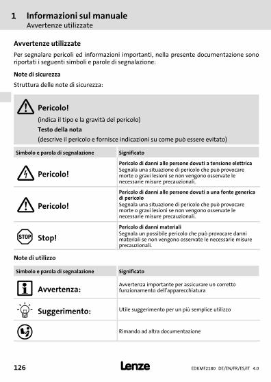
1 Informazioni sul manualeAvvertenze utilizzate
EDKMF2180 DE/EN/FR/ES/IT 4.0126 �
H2_Def_Hinweise−SIC_pikt_IT
Avvertenze utilizzate
Per segnalare pericoli ed informazioni importanti, nella presente documentazione sonoriportati i seguenti simboli e parole di segnalazione:
Note di sicurezza
Struttura delle note di sicurezza:
� Pericolo!(indica il tipo e la gravità del pericolo)
Testo della nota
(descrive il pericolo e fornisce indicazioni su come può essere evitato)
Simbolo e parola di segnalazione Significato
� Pericolo!
Pericolo di danni alle persone dovuti a tensione elettricaSegnala una situazione di pericolo che può provocaremorte o gravi lesioni se non vengono osservate lenecessarie misure precauzionali.
� Pericolo!
Pericolo di danni alle persone dovuti a una fonte genericadi pericoloSegnala una situazione di pericolo che può provocaremorte o gravi lesioni se non vengono osservate lenecessarie misure precauzionali.
� Stop!
Pericolo di danni materialiSegnala un possibile pericolo che può provocare dannimateriali se non vengono osservate le necessarie misureprecauzionali.
Note di utilizzo
Simbolo e parola di segnalazione Significato
� Avvertenza:Avvertenza importante per assicurare un correttofunzionamento dell’apparecchiatura
� Suggerimento: Utile suggerimento per un più semplice utilizzo
� Rimando ad altra documentazione
Informazioni sulla sicurezza 2
EDKMF2180 DE/EN/FR/ES/IT 4.0 127�
H1sic_IT−stop_statEntlad_KommModule
2 Informazioni sulla sicurezza
� Pericolo!Un utilizzo improprio del modulo di comunicazione e del dispositivo base puòcausare gravi danni materiali e alle persone.
Rispettare le informazioni sulla sicurezza e sugli altri pericoli contenute nelladocumentazione relativa al dispositivo base.
� Stop!Scariche elettrostatiche
Eventuali scariche elettrostatiche possono danneggiare o distruggere lecomponenti elettroniche presenti all’interno del modulo di comunicazione.
Possibili conseguenze:ƒ Malfunzionamento del modulo di comunicazioneƒ Comunicazione con bus di campo impossibile o problematica.
Misure di protezioneƒ Prima di toccare il modulo, dissipare le cariche elettrostatiche.

3 Descrizione del prodottoFunzione
EDKMF2180 DE/EN/FR/ES/IT 4.0128 �
−H1−typbez
3 Descrizione del prodotto
Funzione
Il modulo di comunicazione serve per la parametrizzazione o programmazione, messa inservizio e diagnostica dei dispositivi Lenze tramite telecontrollo.
Utilizzo conforme
Il modulo di comunicazione può essere utilizzato con i seguenti dispositivi Lenze:ƒ Servo Drives 9400ƒ Inverter Drives 8400ƒ Servoinverter 9300ƒ 9300 vectorƒ Servo PLC 9300ƒ Servosistema ECSƒ Inverter 8200 motecƒ Inverter 8200 vectorƒ Inverter 82XXƒ Drive PLCƒ Morsettiera di espansione 9374ƒ Unità tastiera/display (EPM−HXXX)ƒ Sistema I/O IP20 (EPM−TXXX)
Oggetto della fornitura
ƒ Modulo di comunicazione EMF2180IB (EthernetCAN)ƒ Istruzioni di montaggio
� Manuale di comunicazione EMF2180IB (EthernetCAN)
Qui è possibile trovare informazioni approfondite.
Il file PDF può essere scaricato nell’area Download all’indirizzowww.lenze.com.
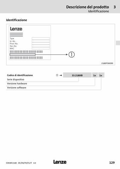
Descrizione del prodottoIdentificazione
3
EDKMF2180 DE/EN/FR/ES/IT 4.0 129�
−H1−typbez
Identificazione
2180FEW099
Codice di identificazione ���� 33.2180IB 1x 1x
Serie dispositivo
Versione hardware
Versione software
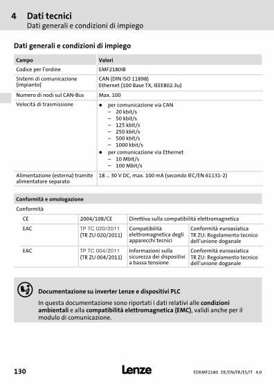
4 Dati tecniciDati generali e condizioni di impiego
EDKMF2180 DE/EN/FR/ES/IT 4.0130 �
H1_Daten−TabAbmess
4 Dati tecnici
Dati generali e condizioni di impiego
Campo Valori
Codice per l’ordine EMF2180IB
Sistemi di comunicazione(impianto)
CAN (DIN ISO 11898)Ethernet (100 Base TX, IEEE802.3u)
Numero di nodi sul CAN−Bus Max. 100
Velocità di trasmissione � per comunicazione via CAN– 20 kbit/s– 50 kbit/s– 125 kbit/s– 250 kbit/s– 500 kbit/s– 1000 kbit/s
� per comunicazione via Ethernet– 10 Mbit/s– 100 Mbit/s
Alimentazione (esterna) tramitealimentatore separato
18 � 30 V DC, max. 100 mA (secondo IEC/EN 61131−2)
Conformità e omologazione
Conformità
CE 2004/108/CE Direttiva sulla compatibilità elettromagnetica
EAC ������������
(TR ZU 020/2011)Compatibilitàelettromagnetica degliapparecchi tecnici
Conformità euroasiaticaTR ZU: Regolamento tecnicodell’unione doganale
EAC �����������
(TR ZU 004/2011)Informazioni sullasicurezza dei dispositivia bassa tensione
Conformità euroasiaticaTR ZU: Regolamento tecnicodell’unione doganale
� Documentazione su inverter Lenze e dispositivi PLC
In questa documentazione sono riportati i dati relativi alle condizioniambientali e alla compatibilità elettromagnetica (EMC), validi anche per ilmodulo di comunicazione.
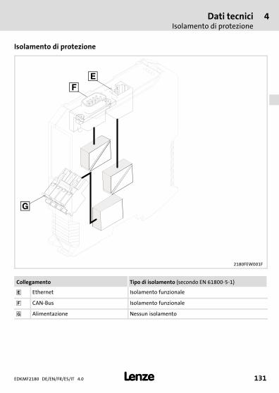
Dati tecniciIsolamento di protezione
4
EDKMF2180 DE/EN/FR/ES/IT 4.0 131�
H1_Daten−TabAbmess
Isolamento di protezione
2180FEW001F
Collegamento Tipo di isolamento (secondo EN 61800−5−1)
� Ethernet Isolamento funzionale
� CAN−Bus Isolamento funzionale
� Alimentazione Nessun isolamento

4 Dati tecniciDimensioni
EDKMF2180 DE/EN/FR/ES/IT 4.0132 �
H1_Daten−TabAbmess
Dimensioni
2180FEW001B
a 117 mm
b 103 mm
e 22.5 mm
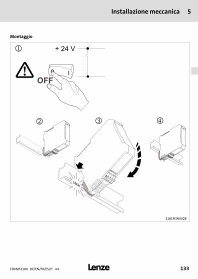
Installazione meccanica 5
EDKMF2180 DE/EN/FR/ES/IT 4.0 133�
H1_MechINS−218x entriegeln
5 Installazione meccanica
Montaggio
2181FEW002B
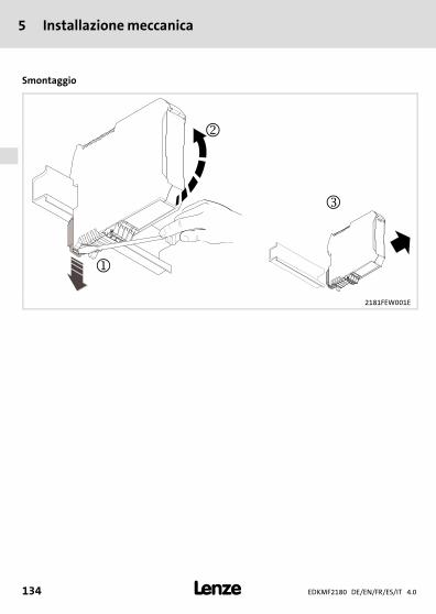
5 Installazione meccanica
EDKMF2180 DE/EN/FR/ES/IT 4.0134 �
H1_MechINS−218x entriegeln
Smontaggio
2181FEW001E
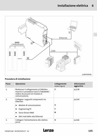
Installazione elettrica 6
EDKMF2180 DE/EN/FR/ES/IT 4.0 135�
H1_E_INST−SteckerFederkraftAnschluss FKCT
6 Installazione elettrica
2180FEW008
Procedura di installazione
Passo Operazione Collegamento(vedere figura)
Informazioniaggiuntive
1. Realizzare il collegamento al CAN−Bus:Inserire il connettore Sub−D ("EWZ0046",vedere Accessori) nel modulo dicomunicazione.
� ��138
2. Collegare i seguenti componenti viaEthernet:
��144
� Modulo di comunicazione �
� Engineering PC �
� Servo Drives 9400 �
� Altri nodi della rete Ethernet
3. Collegare l’alimentazione alla relativapresa.
� ��146
6 Installazione elettricaCablaggio conforme EMC
EDKMF2180 DE/EN/FR/ES/IT 4.0136 �
H1_E_INST−SteckerFederkraftAnschluss FKCT
Cablaggio conforme EMC
Per un cablaggio conforme alla normativa EMC sulla compatibilità elettromagnetica,osservare i seguenti punti:
� Avvertenza:ƒ Posare i cavi di controllo/dati separati dai cavi motore.ƒ Applicare la schermatura dei cavi di controllo/dati in caso di segnali digitali
su entrambi i lati.ƒ Per evitare differenze di potenziale tra i nodi di comunicazione, utilizzare
un cavo di compensazione del potenziale con una sezione di almeno16 mm2 (riferimento:�PE).
ƒ Osservare le note relative al cablaggio EMC nelle istruzioni del dispositivobase.
Procedura per il cablaggio
1. Non cambiare la topologia del bus, quindi non utilizzare linee derivate.2. Osservare le avvertenze e i requisiti del cablaggio nella documentazione del sistema
host (PLC).3. Utilizzare solo cavi conformi alle specifiche (��139).4. Osservare la lunghezza del cavo bus ammissibile (��140).
5. Osservare le avvertenze sull’alimentazione del modulo di comunicazione (��146).6. Attivare resistenze di terminazione bus da 120 � sul primo e sull’ultimo nodo fisico
del bus.
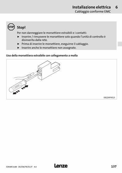
Installazione elettricaCablaggio conforme EMC
6
EDKMF2180 DE/EN/FR/ES/IT 4.0 137�
H1_E_INST−SteckerFederkraftAnschluss FKCT
� Stop!Per non danneggiare le morsettiere estraibili e i contatti:ƒ Inserire / rimuovere le morsettiere solo quando l’unità di controllo è
disinserita dalla rete.ƒ Prima di inserire le morsettiere, eseguirne il cablaggio.ƒ Inserire anche le morsettiere non assegnate.
Uso della morsettiera estraibile con collegamento a molla
E82ZAFX013
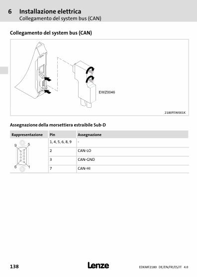
6 Installazione elettricaCollegamento del system bus (CAN)
EDKMF2180 DE/EN/FR/ES/IT 4.0138 �
H1_E_INST−SteckerFederkraftAnschluss FKCT
Collegamento del system bus (CAN)
2180FEW001K
Assegnazione della morsettiera estraibile Sub−D
Rappresentazione Pin Assegnazione
16
59
1, 4, 5, 6, 8, 9 −
2 CAN−LO
3 CAN−GND
7 CAN−HI
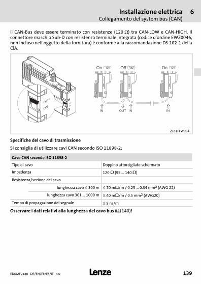
Installazione elettricaCollegamento del system bus (CAN)
6
EDKMF2180 DE/EN/FR/ES/IT 4.0 139�
H1_E_INST−SteckerFederkraftAnschluss FKCT
Il CAN−Bus deve essere terminato con resistenze (120��) tra CAN−LOW e CAN−HIGH. Ilconnettore maschio Sub−D con resistenza terminale integrata (codice d’ordine EWZ0046,non incluso nell’oggetto della fornitura) è conforme alla raccomandazione DS 102−1 dellaCiA.
L
EW
Z0046
OFF
ON
OFF
ON
ON
OFF
�
� � �
OUTIN IN IN
On Off On120 120 120
LE
WZ
00
46
LE
WZ
00
46
LE
WZ
00
46
2181FEW004
Specifiche del cavo di trasmissione
Si consiglia di utilizzare cavi CAN secondo ISO 11898−2:
Cavo CAN secondo ISO 11898−2
Tipo di cavo Doppino attorcigliato schermato
Impedenza 120 � (95 ... 140 �)
Resistenza/sezione del cavo
lunghezza cavo � 300 m � 70 m�/m / 0.25 � 0.34 mm2 (AWG 22)
lunghezza cavo 301 � 1000 m � 40 m�/m / 0.5 mm2 (AWG20)
Tempo di propagazione del segnale � 5 ns/m
Osservare i dati relativi alla lunghezza del cavo bus (��140)!
6 Installazione elettricaCollegamento del system bus (CAN)
EDKMF2180 DE/EN/FR/ES/IT 4.0140 �
H1_E_INST−SteckerFederkraftAnschluss FKCT
Lunghezza cavi bus
� Avvertenza:ƒ Rispettare le lunghezze cavo consentite.ƒ Se a parità di velocità di trasmissione le lunghezze totali dei cavi dei nodi
CAN sono diverse, per la determinazione della lunghezza cavo max. ènecessario utilizzare il valore più piccolo.
ƒ Osservare la riduzione della lunghezza totale del cavo in considerazione delritardo di segnale del ripetitore.
Lunghezza cavo totale
La velocità di trasmissione permette di determinare la lunghezza totale del cavo.
Velocità di trasmissione [kbit/s] Lunghezza bus max. [m]
10 7450
20 3950
50 1550
125 630
250 290
500 120
1000 25
Tab. 1 Lunghezza totale del cavo
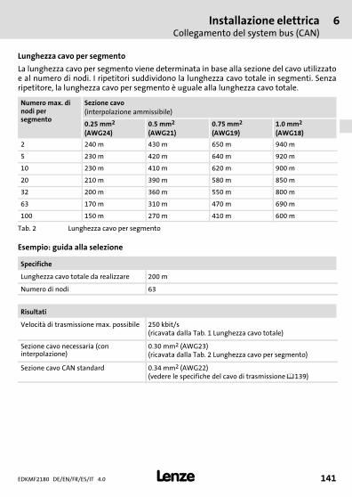
Installazione elettricaCollegamento del system bus (CAN)
6
EDKMF2180 DE/EN/FR/ES/IT 4.0 141�
H1_E_INST−SteckerFederkraftAnschluss FKCT
Lunghezza cavo per segmento
La lunghezza cavo per segmento viene determinata in base alla sezione del cavo utilizzatoe al numero di nodi. I ripetitori suddividono la lunghezza cavo totale in segmenti. Senzaripetitore, la lunghezza cavo per segmento è uguale alla lunghezza cavo totale.
Numero max. dinodi persegmento
Sezione cavo(interpolazione ammissibile)
0.25 mm2
(AWG24)0.5 mm2
(AWG21)0.75 mm2
(AWG19)1.0 mm2
(AWG18)
2 240 m 430 m 650 m 940 m
5 230 m 420 m 640 m 920 m
10 230 m 410 m 620 m 900 m
20 210 m 390 m 580 m 850 m
32 200 m 360 m 550 m 800 m
63 170 m 310 m 470 m 690 m
100 150 m 270 m 410 m 600 m
Tab. 2 Lunghezza cavo per segmento
Esempio: guida alla selezione
Specifiche
Lunghezza cavo totale da realizzare 200 m
Numero di nodi 63
Risultati
Velocità di trasmissione max. possibile 250 kbit/s(ricavata dalla Tab. 1 Lunghezza cavo totale)
Sezione cavo necessaria (coninterpolazione)
0.30 mm2 (AWG23)(ricavata dalla Tab. 2 Lunghezza cavo per segmento)
Sezione cavo CAN standard 0.34 mm2 (AWG22)(vedere le specifiche del cavo di trasmissione ��139)
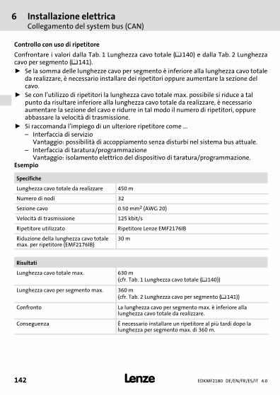
6 Installazione elettricaCollegamento del system bus (CAN)
EDKMF2180 DE/EN/FR/ES/IT 4.0142 �
H1_E_INST−SteckerFederkraftAnschluss FKCT
Controllo con uso di ripetitore
Confrontare i valori dalla Tab. 1 Lunghezza cavo totale (��140) e dalla Tab. 2 Lunghezzacavo per segmento (��141).ƒ Se la somma delle lunghezze cavo per segmento è inferiore alla lunghezza cavo totale
da realizzare, è necessario installare dei ripetitori oppure aumentare la sezione delcavo.
ƒ Se con l’utilizzo di ripetitori la lunghezza cavo totale max. possibile si riduce a talpunto da risultare inferiore alla lunghezza cavo totale da realizzare, è necessarioaumentare la sezione del cavo e ridurre in tal modo il numero di ripetitori, oppureabbassare la velocità di trasmissione.
ƒ Si raccomanda l’impiego di un ulteriore ripetitore come ...– Interfaccia di servizio
Vantaggio: possibilità di accoppiamento senza disturbi nel sistema bus attuale.– Interfaccia di taratura/programmazione
Vantaggio: isolamento elettrico del dispositivo di taratura/programmazione.Esempio
Specifiche
Lunghezza cavo totale da realizzare 450 m
Numero di nodi 32
Sezione cavo 0.50 mm2 (AWG 20)
Velocità di trasmissione 125 kbit/s
Ripetitore utilizzato Ripetitore Lenze EMF2176IB
Riduzione della lunghezza cavo totalemax. per ripetitore (EMF2176IB)
30 m
Risultati
Lunghezza cavo totale max. 630 m(cfr. Tab. 1 Lunghezza cavo totale (��140))
Lunghezza cavo per segmento max. 360 m(cfr. Tab. 2 Lunghezza cavo per segmento (��141))
Confronto La lunghezza cavo per segmento max. è inferiore allalunghezza cavo totale da realizzare.
Conseguenza È necessario installare un ripetitore al più tardi dopo lalunghezza per segmento max. di 360 m.
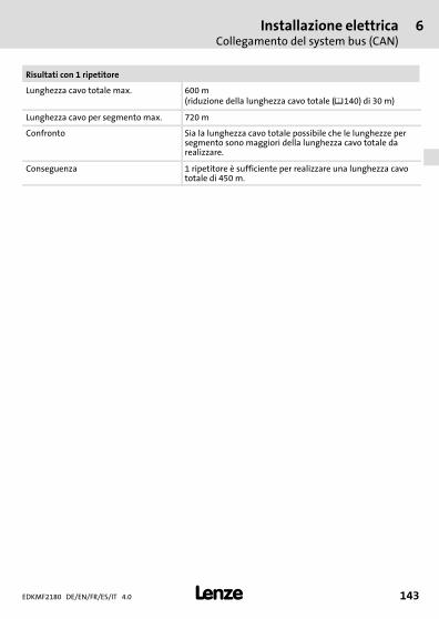
Installazione elettricaCollegamento del system bus (CAN)
6
EDKMF2180 DE/EN/FR/ES/IT 4.0 143�
H1_E_INST−SteckerFederkraftAnschluss FKCT
Risultati con 1 ripetitore
Lunghezza cavo totale max. 600 m(riduzione della lunghezza cavo totale (��140) di 30 m)
Lunghezza cavo per segmento max. 720 m
Confronto Sia la lunghezza cavo totale possibile che le lunghezze persegmento sono maggiori della lunghezza cavo totale darealizzare.
Conseguenza 1 ripetitore è sufficiente per realizzare una lunghezza cavototale di 450 m.
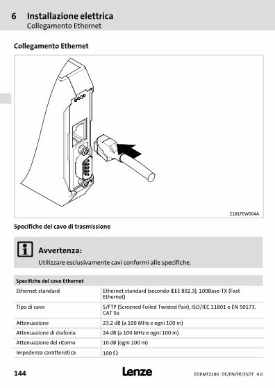
6 Installazione elettricaCollegamento Ethernet
EDKMF2180 DE/EN/FR/ES/IT 4.0144 �
H1_E_INST−SteckerFederkraftAnschluss FKCT
Collegamento Ethernet
2181FEW004A
Specifiche del cavo di trasmissione
� Avvertenza:Utilizzare esclusivamente cavi conformi alle specifiche.
Specifiche del cavo Ethernet
Ethernet standard Ethernet standard (secondo IEEE 802.3), 100Base−TX (FastEthernet)
Tipo di cavo S/FTP (Screened Foiled Twisted Pair), ISO/IEC 11801 o EN 50173,CAT 5e
Attenuazione 23.2 dB (a 100 MHz e ogni 100 m)
Attenuazione di diafonia 24 dB (a 100 MHz e ogni 100 m)
Attenuazione del ritorno 10 dB (ogni 100 m)
Impedenza caratteristica 100 �
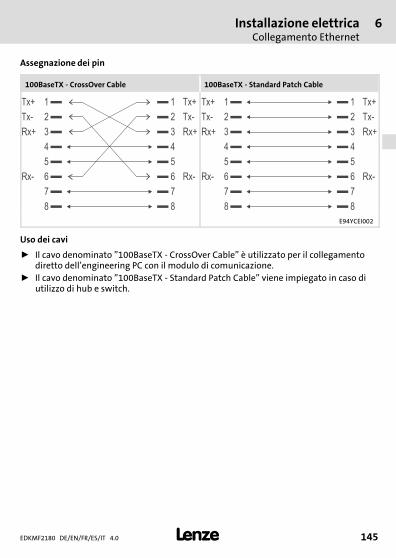
Installazione elettricaCollegamento Ethernet
6
EDKMF2180 DE/EN/FR/ES/IT 4.0 145�
H1_E_INST−SteckerFederkraftAnschluss FKCT
Assegnazione dei pin
100BaseTX − CrossOver Cable 100BaseTX − Standard Patch Cable
1Tx+ Tx+1
2Tx- Tx-2
3Rx+ Rx+3
4 4
5 5
6Rx- Rx-6
7 7
8 8
1Tx+ Tx+1
2Tx- Tx-2
3Rx+ Rx+3
4 4
5 5
6Rx- Rx-6
7 7
8 8
E94YCEI002
Uso dei cavi
ƒ Il cavo denominato "100BaseTX − CrossOver Cable" è utilizzato per il collegamentodiretto dell’engineering PC con il modulo di comunicazione.
ƒ Il cavo denominato "100BaseTX − Standard Patch Cable" viene impiegato in caso diutilizzo di hub e switch.
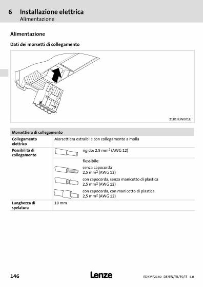
6 Installazione elettricaAlimentazione
EDKMF2180 DE/EN/FR/ES/IT 4.0146 �
H1_E_INST−SteckerFederkraftAnschluss FKCT
Alimentazione
Dati dei morsetti di collegamento
2181FEW001G
Morsettiera di collegamento
Collegamentoelettrico
Morsettiera estraibile con collegamento a molla
Possibilità dicollegamento
rigido: 2,5 mm2 (AWG 12)
flessibile:
senza capocorda2,5 mm2 (AWG 12)
con capocorda, senza manicotto di plastica2,5 mm2 (AWG 12)
con capocorda, con manicotto di plastica2,5 mm2 (AWG 12)
Lunghezza dispelatura
10 mm
Messa in servizioPrima dell’accensione
7
EDKMF2180 DE/EN/FR/ES/IT 4.0 147�
H1inbet−LESE_INB_KHB_Fernwartung
7 Messa in servizio
Prima dell’accensione
� Stop!Prima dell’accensione dell’alimentazione di rete, controllare l’intero cablaggioper accertarne la completezza, l’assenza di cortocircuiti e la messa a terra.
� Manuale di comunicazione EMF2180IB (EthernetCAN)
Questo manuale contiene informazioni approfondite sulla messa in servizio.

8 DiagnosticaIndicatori di stato a LED
EDKMF2180 DE/EN/FR/ES/IT 4.0148 �
H1_Diagnose−st_00tu0
8 Diagnostica
Indicatori di stato a LED
2180FEW001H
Pos. Colore Stato Descrizione
(B)
giallo spento Velocità di trasmissione: 10 MBit/s
acceso Velocità di trasmissione: 100 MBit/s
lampeggia L’indirizzo IP del modulo di comunicazione non èancora assegnato; processo di rilevamento incorso.
�(E)
rosso vedere��148 LED ERR
�(R)
verde LED RUN
(P)
verde acceso Il modulo di comunicazione riceve correttamentela tensione di alimentazione.
� verde acceso Collegamento alla rete Ethernet presente (LINK).
� verde acceso o lampeggiaÈ in corso l’invio o il ricevimento di dati.(ACTIVITY).
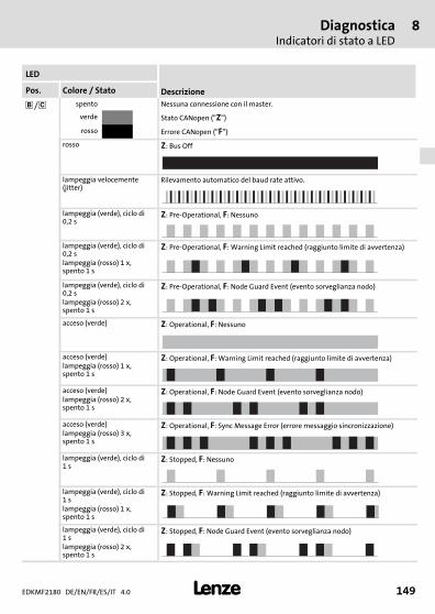
DiagnosticaIndicatori di stato a LED
8
EDKMF2180 DE/EN/FR/ES/IT 4.0 149�
H1_Diagnose−st_00tu0
LED
DescrizionePos. Colore / Stato
��/ � spento Nessuna connessione con il master.
verde Stato CANopen ("Z")
rosso Errore CANopen ("F")
rosso Z: Bus Off
lampeggia velocemente(jitter)
Rilevamento automatico del baud rate attivo.
lampeggia (verde), ciclo di0,2 s
Z: Pre−Operational, F: Nessuno
lampeggia (verde), ciclo di0,2 slampeggia (rosso) 1 x,spento 1 s
Z: Pre−Operational, F: Warning Limit reached (raggiunto limite di avvertenza)
lampeggia (verde), ciclo di0,2 slampeggia (rosso) 2 x,spento 1 s
Z: Pre−Operational, F: Node Guard Event (evento sorveglianza nodo)
acceso (verde) Z: Operational, F: Nessuno
acceso (verde)lampeggia (rosso) 1 x,spento 1 s
Z: Operational, F: Warning Limit reached (raggiunto limite di avvertenza)
acceso (verde)lampeggia (rosso) 2 x,spento 1 s
Z: Operational, F: Node Guard Event (evento sorveglianza nodo)
acceso (verde)lampeggia (rosso) 3 x,spento 1 s
Z: Operational, F: Sync Message Error (errore messaggio sincronizzazione)
lampeggia (verde), ciclo di1 s
Z: Stopped, F: Nessuno
lampeggia (verde), ciclo di1 slampeggia (rosso) 1 x,spento 1 s
Z: Stopped, F: Warning Limit reached (raggiunto limite di avvertenza)
lampeggia (verde), ciclo di1 slampeggia (rosso) 2 x,spento 1 s
Z: Stopped, F: Node Guard Event (evento sorveglianza nodo)
backside
� �© 08/2014
� Lenze Automation GmbHPostfach 10 13 52, D−31763 HamelnHans−Lenze−Str. 1, D−31855 AerzenGermany
Service Lenze Service GmbHBreslauer Straße 3, D−32699 Extertal
Germany
� +49�5154 82−0 � 008000�2446877 (24 h helpline)
� +49�5154 82−2800 � +49�5154�82−1112
� [email protected] � [email protected]
� www.lenze.com
EDKMF2180 � .O÷! � DE/EN/FR/ES/IT � 4.0 � TD17
10 9 8 7 6 5 4 3 2 1